Embed Size (px)
Citation preview

1 Psiber Data Systems Revision 2.01
PingerPro User Guide
USER GUIDE
PingerPro Model 70/71/75/76
2 Psiber Data Systems Revision 2.01
PingerPro User Guide
Copyright This guide is copyrighted by Psiber Data Systems Inc. with all rights reserved. Under the copyright laws, this guide cannot be reproduced in any form without the prior written permission of Psiber Data Systems Inc. No patent liability is assumed, however, with respect to the use of the information contained herein. © Copyright 2014 by Psiber Data Systems Inc. All rights reserved. Notice Every effort was made to ensure that the information in this document was accurate at the time of printing. However, information is subject to change without notice, and Psiber DataSystems reserves the right to provide an addendum to this document with information not available at the time that this document was created. PSIBER DATA SYSTEMS INC. PROVIDE NO WARRANTY WITH REGARD TO THIS MANUAL OR ANY OTHER INFORMATION CONTAINED HEREIN AND HEREBY EXPRESSLY DISCLAIM ANY IMPLIED WARRANTIES OF MERCHANTABILITY OR FITNESS FOR ANY PARTICULAR PURPOSE WITH REGARD TO ANY OF THE FOREGOING. PSIBER ASSUMES NO LIABILITY FOR ANY DAMAGES INCURRED DIRECTLY OR INDIRECTLY FROM ANY TECHNICAL OR TYPOGRAPHICAL ERRORS OR OMISSIONS CONTAINED HEREIN OR FOR DISCREPANCIES BETWEEN THE PRODUCT AND THE MANUAL. IN NO EVENT SHALL PSIBER BE LIABLE FOR ANY INCIDENTAL, CONSEQUENTIAL, SPECIAL, OR EXEMPLARY DAMAGES, WHETHER BASED ON TORT, CONTRACT OR OTHERWISE ARISING OUT OF OR IN CONNECTION WITH THIS MANUAL OR ANYOTHER INFORMATION CONTAINED HEREIN OR THE USE THEREOF. Trademarks The Psiber Logo, Psiber and PingerPro are trademarks of Psiber Data Systems Inc. All other brands and product names are trademarks or registered trademarks of their respective companies. Warranty/Service Option Psiber Data Systems Inc. warrants that the product shall be free from defects in parts or workmanship for a period of 12 months from the date of purchase if used in accordance with Psiber Data Systems Inc. operating specifications. THIS IS THE ONLY WARRANTY MADE BY PSIBER DATA SYSTEMS INC. AND IS EXPRESSLY MADE IN LIEU OF ALL OTHER WARRANTIES, EXPRESSED OR IMPLIED, INCLUDING BUT NOT LIMITED TO ANY IMPLIED WARRANTIES OF MERCHANTABILITY OR FITNESS FOR ANY PARTICULAR PURPOSE. Should any parts or workmanship prove defective, Psiber Data Systems Inc. will repair or replace at Psiber’s discretion, with no cost to the Buyer except for shipping costs from the Buyer’s location to Psiber’s location. This is the Buyer’s SOLE AND EXCLUSIVE REMEDY under this agreement. This warranty does not apply to products which have been subject to neglect, accident or improper use, or to units which have been altered or repaired by other than an authorized repair facility. Return of Equipment - Return of product to Psiber Data Systems Inc. requires a Return Merchandise Authorization (RMA) issued by Customer Service. To obtain an RMA, contact us at 619-287-9970 (8am to 4pm PST) or email [email protected]. The RMA# must be clearly marked on the shipping label or package. See sample label:
To: Psiber Data Systems Inc. 7075-K Mission Gorge Rd.
San Diego, CA 92120 RMA# XXXXXXX
3 Psiber Data Systems Revision 2.01
PingerPro User Guide
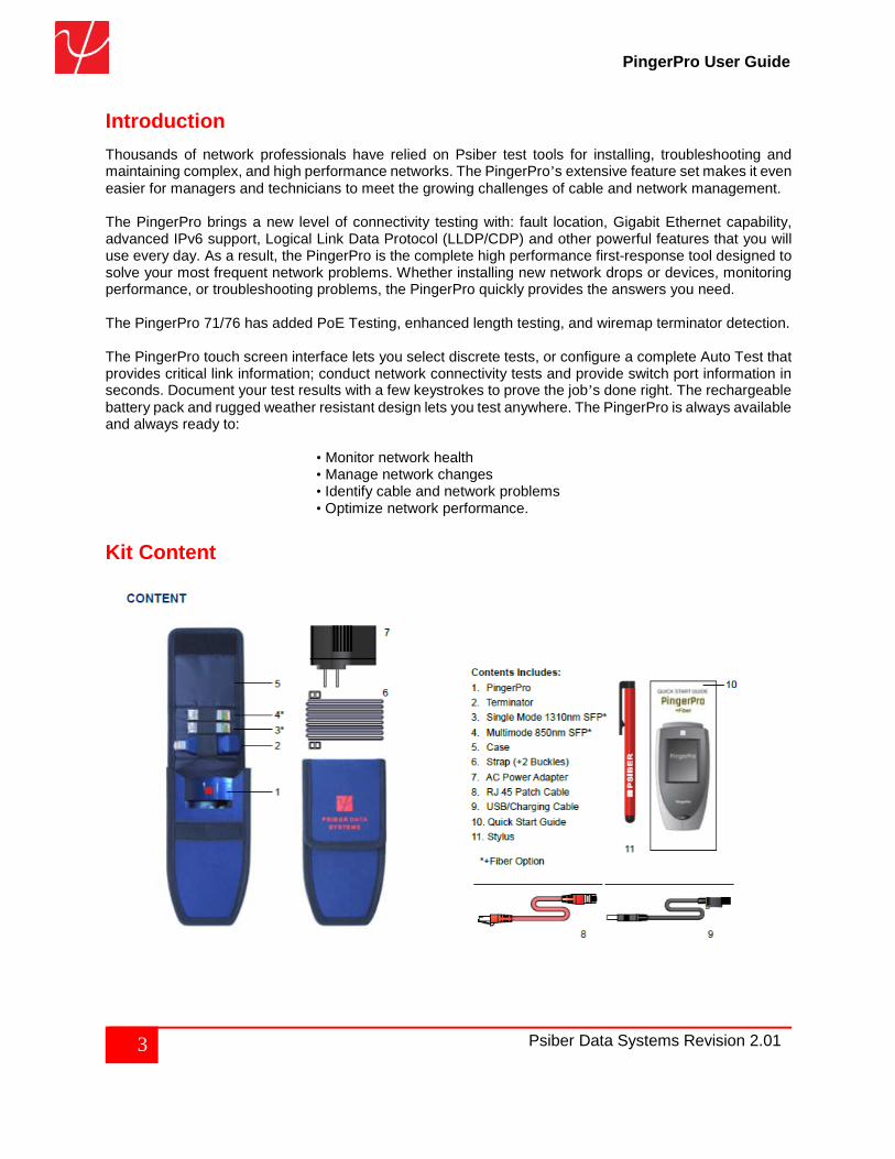
Introduction Thousands of network professionals have relied on Psiber test tools for installing, troubleshooting and maintaining complex, and high performance networks. The PingerPro’s extensive feature set makes it even easier for managers and technicians to meet the growing challenges of cable and network management. The PingerPro brings a new level of connectivity testing with: fault location, Gigabit Ethernet capability, advanced IPv6 support, Logical Link Data Protocol (LLDP/CDP) and other powerful features that you will use every day. As a result, the PingerPro is the complete high performance first-response tool designed to solve your most frequent network problems. Whether installing new network drops or devices, monitoring performance, or troubleshooting problems, the PingerPro quickly provides the answers you need. The PingerPro 71/76 has added PoE Testing, enhanced length testing, and wiremap terminator detection. The PingerPro touch screen interface lets you select discrete tests, or configure a complete Auto Test that provides critical link information; conduct network connectivity tests and provide switch port information in seconds. Document your test results with a few keystrokes to prove the job’s done right. The rechargeable battery pack and rugged weather resistant design lets you test anywhere. The PingerPro is always available and always ready to: • Monitor network health • Manage network changes • Identify cable and network problems • Optimize network performance. Kit Content
4 Psiber Data Systems Revision 2.01
PingerPro User Guide
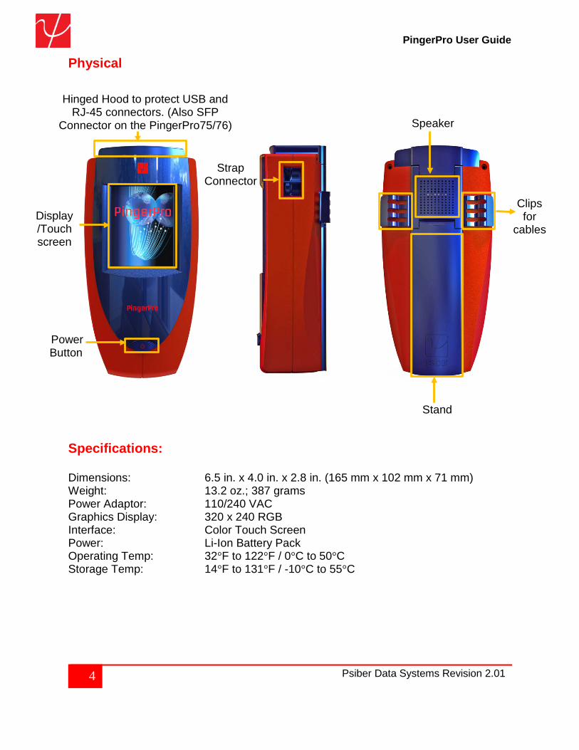
Physical
Specifications: Dimensions: 6.5 in. x 4.0 in. x 2.8 in. (165 mm x 102 mm x 71 mm) Weight: 13.2 oz.; 387 grams Power Adaptor: 110/240 VAC Graphics Display: 320 x 240 RGB Interface: Color Touch Screen Power: Li-Ion Battery Pack Operating Temp: 32°F to 122°F / 0°C to 50°C Storage Temp: 14°F to 131°F / -10°C to 55°C
Power Button
Display/Touchscreen
Strap Connector
Stand
Clips for
cables
Speaker
Hinged Hood to protect USB and RJ-45 connectors. (Also SFP
Connector on the PingerPro75/76)
5 Psiber Data Systems Revision 2.01
PingerPro User Guide
Preparing the Unit The PingerPro is portable and can be hand held or placed on a surface large enough for stable use. The PingerPro is designed to withstand the rigors of everyday use and travel. However, to keep your tester in prime operating condition, please observe the following precautions to further reduce the risk of personal injury or damage to the tester.
▪ Never apply heavy pressure to the tester, especially on or around the display area. Excessive pressure or impact can damage components or otherwise cause the tester to malfunction.
▪ Do not submerge, float or allow liquids to spill into or onto the tester. ▪ Do not use excessive force while connecting or disconnecting cables or peripherals. ▪ Use the supplied strap to prevent accidentally dropping the tester. ▪ Never use sharp objects on the display/touch screen area. Use only the supplied stylus.
Protect the PingerPro from; dust, moisture, direct sunlight, liquids and corrosive materials. Equipment that generates a strong electromagnetic field, rapid changes in temperature or humidity, extreme heat or cold may also damage your tester. Operate the tester within the specified temperature range. Battery Use: The tester contains a rechargeable battery pack which comes charged from the factory for quick use. The external USB adapter provides power to the tester and charges the battery pack from an AC outlet or computer. The battery pack can be charged while the tester is on or off. Charging time is reduced if the tester is turned off. With the tester turned on, the battery symbol on the display provides the charge status of the battery pack.
Caution:
To avoid electric shock, never modify, forcibly bend, damage, apply heat to or place heavy objects on top of the power cord. If the power cable becomes damaged or the plug overheats, discontinue use.
Never remove the power plug from the outlet with wet hands.
Using the wrong AC adapter could damage your tester. Psiber assumes no liability for damage in such cases. Never pull directly on the power cable to unplug it. Hold the power plug when removing the cable from the outlet.
6 Psiber Data Systems Revision 2.01
PingerPro User Guide
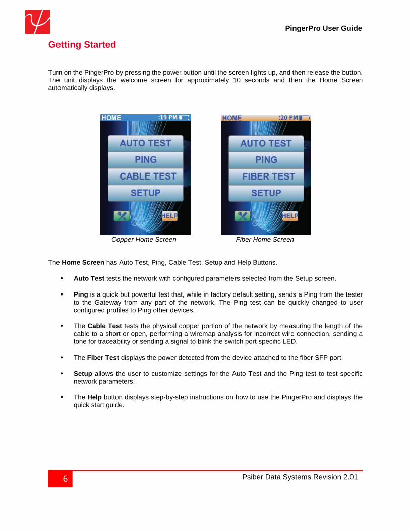
Getting Started Turn on the PingerPro by pressing the power button until the screen lights up, and then release the button. The unit displays the welcome screen for approximately 10 seconds and then the Home Screen automatically displays.
Copper Home Screen Fiber Home Screen
The Home Screen has Auto Test, Ping, Cable Test, Setup and Help Buttons.
• Auto Test tests the network with configured parameters selected from the Setup screen.
• Ping is a quick but powerful test that, while in factory default setting, sends a Ping from the tester to the Gateway from any part of the network. The Ping test can be quickly changed to user configured profiles to Ping other devices.
• The Cable Test tests the physical copper portion of the network by measuring the length of the
cable to a short or open, performing a wiremap analysis for incorrect wire connection, sending a tone for traceability or sending a signal to blink the switch port specific LED.
• The Fiber Test displays the power detected from the device attached to the fiber SFP port.
• Setup allows the user to customize settings for the Auto Test and the Ping test to test specific network parameters.
• The Help button displays step-by-step instructions on how to use the PingerPro and displays the
quick start guide.
7 Psiber Data Systems Revision 2.01
PingerPro User Guide
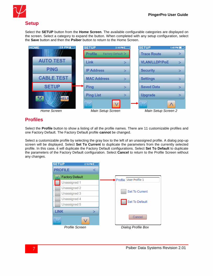
Setup Select the SETUP button from the Home Screen. The available configurable categories are displayed on the screen. Select a category to expand the button. When completed with any setup configuration, select the Save button and then the Psiber button to return to the Home Screen.
Home Screen Main Setup Screen Main Setup Screen 2 Profiles Select the Profile button to show a listing of all the profile names. There are 11 customizable profiles and one Factory Default. The Factory Default profile cannot be changed. Select a customizable profile by selecting the gray box to the left of an unassigned profile. A dialog pop-up screen will be displayed. Select Set To Current to duplicate the parameters from the currently selected profile. In this case, it will duplicate the Factory Default configurations. Select Set To Default to duplicate the parameters of the Factory Default configuration. Select Cancel to return to the Profile Screen without any changes.
Profile Screen Dialog Profile Box
8 Psiber Data Systems Revision 2.01
PingerPro User Guide
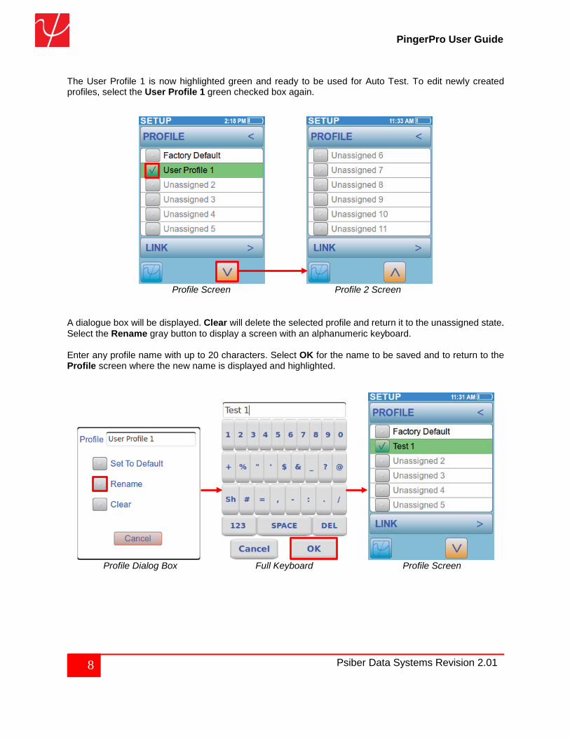
The User Profile 1 is now highlighted green and ready to be used for Auto Test. To edit newly created profiles, select the User Profile 1 green checked box again.
Profile Screen Profile 2 Screen
A dialogue box will be displayed. Clear will delete the selected profile and return it to the unassigned state. Select the Rename gray button to display a screen with an alphanumeric keyboard. Enter any profile name with up to 20 characters. Select OK for the name to be saved and to return to the Profile screen where the new name is displayed and highlighted.
Profile Dialog Box Full Keyboard Profile Screen
9 Psiber Data Systems Revision 2.01
PingerPro User Guide
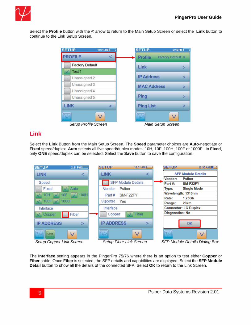
Select the Profile button with the < arrow to return to the Main Setup Screen or select the Link button to continue to the Link Setup Screen.
Setup Profile Screen Main Setup Screen
Link Select the Link Button from the Main Setup Screen. The Speed parameter choices are Auto-negotiate or Fixed speed/duplex. Auto selects all five speed/duplex modes; 10H, 10F, 100H, 100F or 1000F. In Fixed, only ONE speed/duplex can be selected. Select the Save button to save the configuration.
Setup Copper Link Screen Setup Fiber Link Screen SFP Module Details Dialog Box The Interface setting appears in the PingerPro 75/76 where there is an option to test either Copper or Fiber cable. Once Fiber is selected, the SFP details and capabilities are displayed. Select the SFP Module Detail button to show all the details of the connected SFP. Select OK to return to the Link Screen.
10 Psiber Data Systems Revision 2.01
PingerPro User Guide
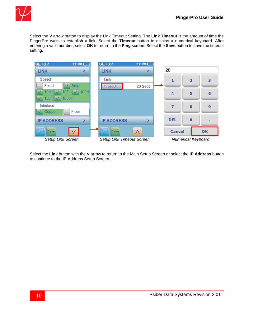
Select the V arrow button to display the Link Timeout Setting. The Link Timeout is the amount of time the PingerPro waits to establish a link. Select the Timeout button to display a numerical keyboard. After entering a valid number, select OK to return to the Ping screen. Select the Save button to save the timeout setting.
Setup Link Screen Setup Link Timeout Screen Numerical Keyboard Select the Link button with the < arrow to return to the Main Setup Screen or select the IP Address button to continue to the IP Address Setup Screen.
11 Psiber Data Systems Revision 2.01
PingerPro User Guide
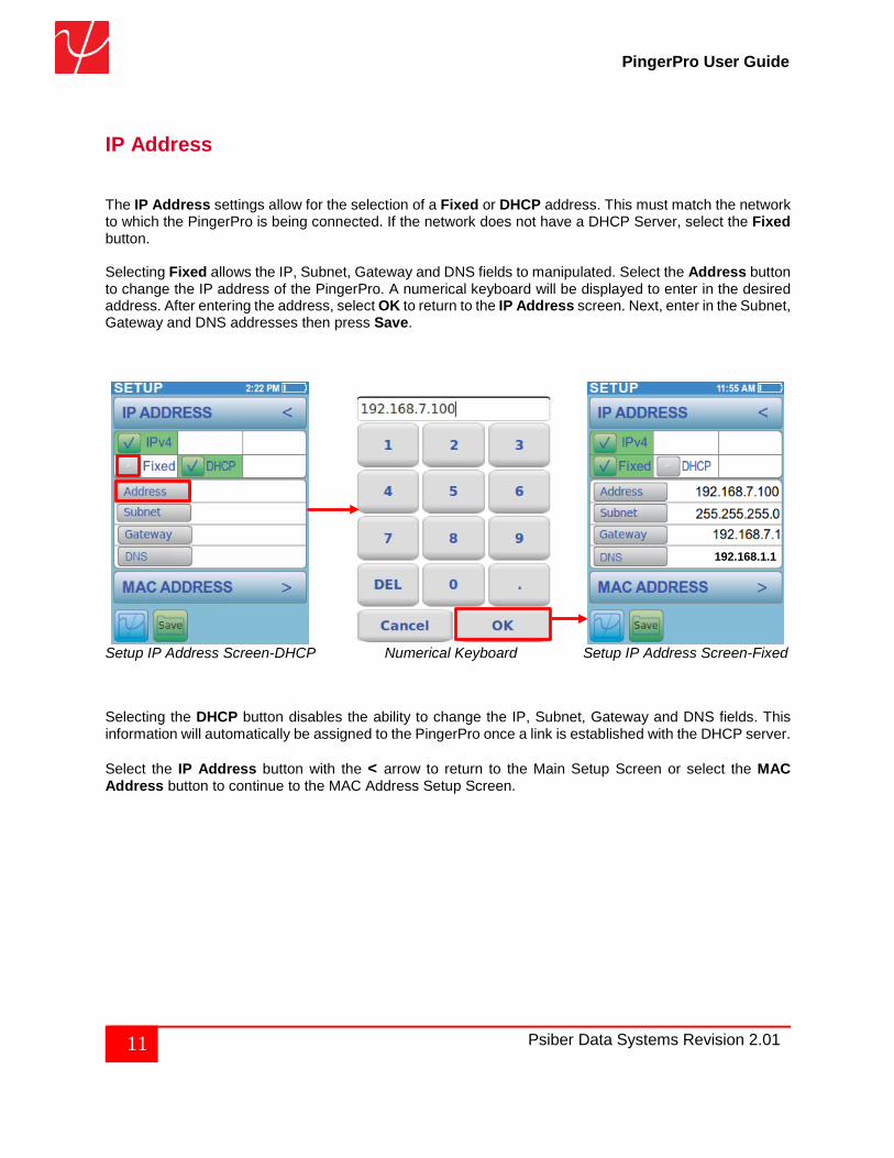
IP Address The IP Address settings allow for the selection of a Fixed or DHCP address. This must match the network to which the PingerPro is being connected. If the network does not have a DHCP Server, select the Fixed button. Selecting Fixed allows the IP, Subnet, Gateway and DNS fields to manipulated. Select the Address button to change the IP address of the PingerPro. A numerical keyboard will be displayed to enter in the desired address. After entering the address, select OK to return to the IP Address screen. Next, enter in the Subnet, Gateway and DNS addresses then press Save.
Setup IP Address Screen-DHCP Numerical Keyboard Setup IP Address Screen-Fixed
Selecting the DHCP button disables the ability to change the IP, Subnet, Gateway and DNS fields. This information will automatically be assigned to the PingerPro once a link is established with the DHCP server. Select the IP Address button with the < arrow to return to the Main Setup Screen or select the MAC Address button to continue to the MAC Address Setup Screen.
192.168.1.1
12 Psiber Data Systems Revision 2.01
PingerPro User Guide
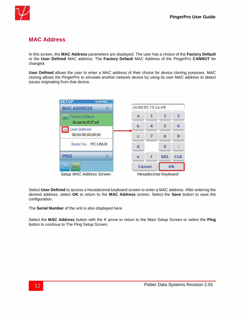
MAC Address In this screen, the MAC Address parameters are displayed. The user has a choice of the Factory Default or the User Defined MAC address. The Factory Default MAC Address of the PingerPro CANNOT be changed. User Defined allows the user to enter a MAC address of their choice for device cloning purposes. MAC cloning allows the PingerPro to simulate another network device by using its own MAC address to detect issues originating from that device.
Setup MAC Address Screen Hexadecimal Keyboard
Select User Defined to access a hexadecimal keyboard screen to enter a MAC address. After entering the desired address, select OK to return to the MAC Address screen. Select the Save button to save the configuration. The Serial Number of the unit is also displayed here.
Select the MAC Address button with the < arrow to return to the Main Setup Screen or select the Ping button to continue to The Ping Setup Screen.
13 Psiber Data Systems Revision 2.01
PingerPro User Guide
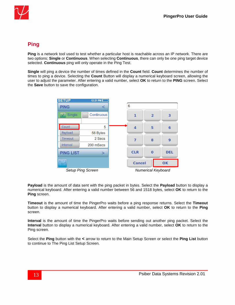
Ping Ping is a network tool used to test whether a particular host is reachable across an IP network. There are two options; Single or Continuous. When selecting Continuous, there can only be one ping target device selected. Continuous ping will only operate in the Ping Test. Single will ping a device the number of times defined in the Count field. Count determines the number of times to ping a device. Selecting the Count Button will display a numerical keyboard screen, allowing the user to adjust the parameter. After entering a valid number, select OK to return to the PING screen. Select the Save button to save the configuration.
Setup Ping Screen Numerical Keyboard
Payload is the amount of data sent with the ping packet in bytes. Select the Payload button to display a numerical keyboard. After entering a valid number between 56 and 1518 bytes, select OK to return to the Ping screen. Timeout is the amount of time the PingerPro waits before a ping response returns. Select the Timeout button to display a numerical keyboard. After entering a valid number, select OK to return to the Ping screen. Interval is the amount of time the PingerPro waits before sending out another ping packet. Select the Interval button to display a numerical keyboard. After entering a valid number, select OK to return to the Ping screen. Select the Ping button with the < arrow to return to the Main Setup Screen or select the Ping List button to continue to The Ping List Setup Screen.
14 Psiber Data Systems Revision 2.01
PingerPro User Guide
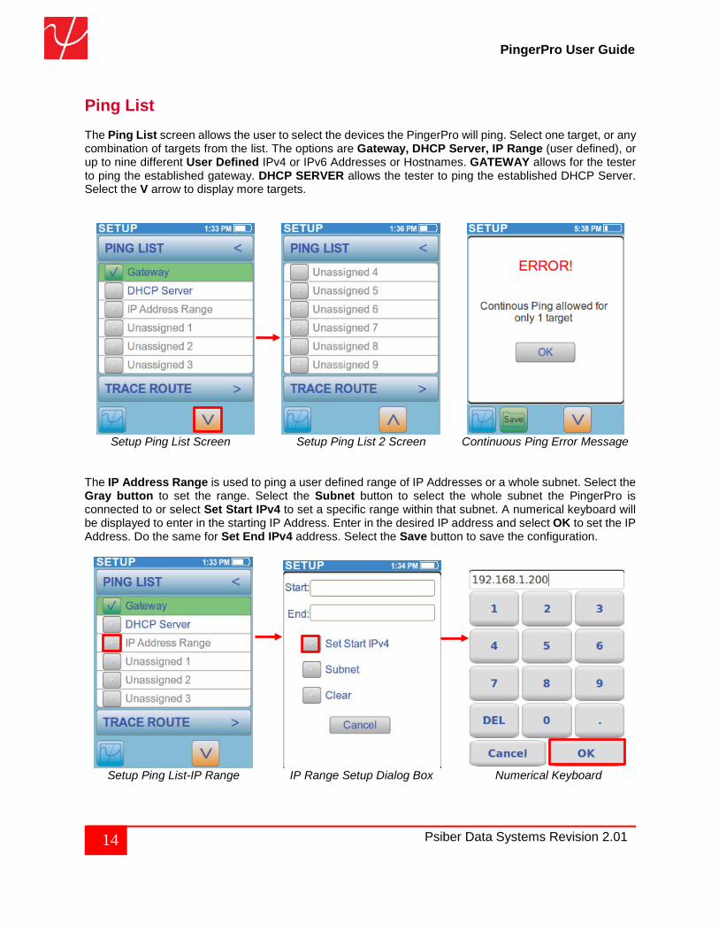
Ping List The Ping List screen allows the user to select the devices the PingerPro will ping. Select one target, or any combination of targets from the list. The options are Gateway, DHCP Server, IP Range (user defined), or up to nine different User Defined IPv4 or IPv6 Addresses or Hostnames. GATEWAY allows for the tester to ping the established gateway. DHCP SERVER allows the tester to ping the established DHCP Server. Select the V arrow to display more targets.
Setup Ping List Screen Setup Ping List 2 Screen Continuous Ping Error Message
The IP Address Range is used to ping a user defined range of IP Addresses or a whole subnet. Select the Gray button to set the range. Select the Subnet button to select the whole subnet the PingerPro is connected to or select Set Start IPv4 to set a specific range within that subnet. A numerical keyboard will be displayed to enter in the starting IP Address. Enter in the desired IP address and select OK to set the IP Address. Do the same for Set End IPv4 address. Select the Save button to save the configuration.
Setup Ping List-IP Range IP Range Setup Dialog Box Numerical Keyboard
15 Psiber Data Systems Revision 2.01
PingerPro User Guide
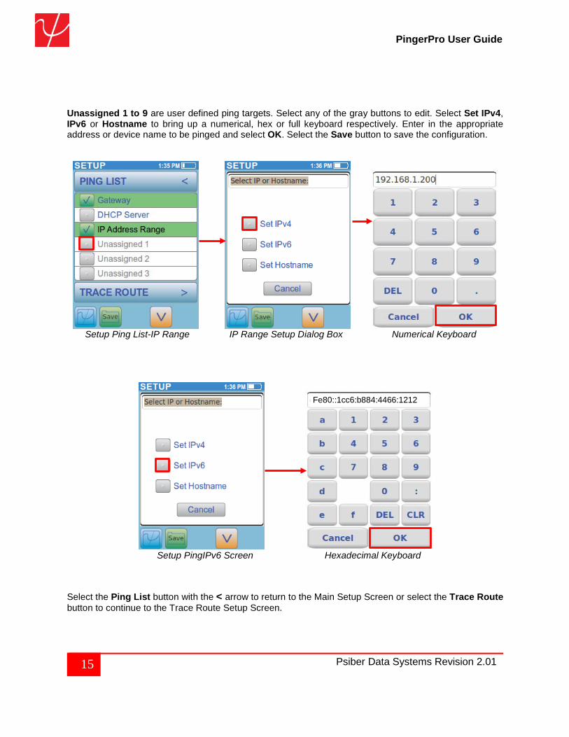
Unassigned 1 to 9 are user defined ping targets. Select any of the gray buttons to edit. Select Set IPv4, IPv6 or Hostname to bring up a numerical, hex or full keyboard respectively. Enter in the appropriate address or device name to be pinged and select OK. Select the Save button to save the configuration.
Setup Ping List-IP Range IP Range Setup Dialog Box Numerical Keyboard
Setup PingIPv6 Screen Hexadecimal Keyboard
Select the Ping List button with the < arrow to return to the Main Setup Screen or select the Trace Route button to continue to the Trace Route Setup Screen.
Fe80::1cc6:b884:4466:1212
16 Psiber Data Systems Revision 2.01
PingerPro User Guide
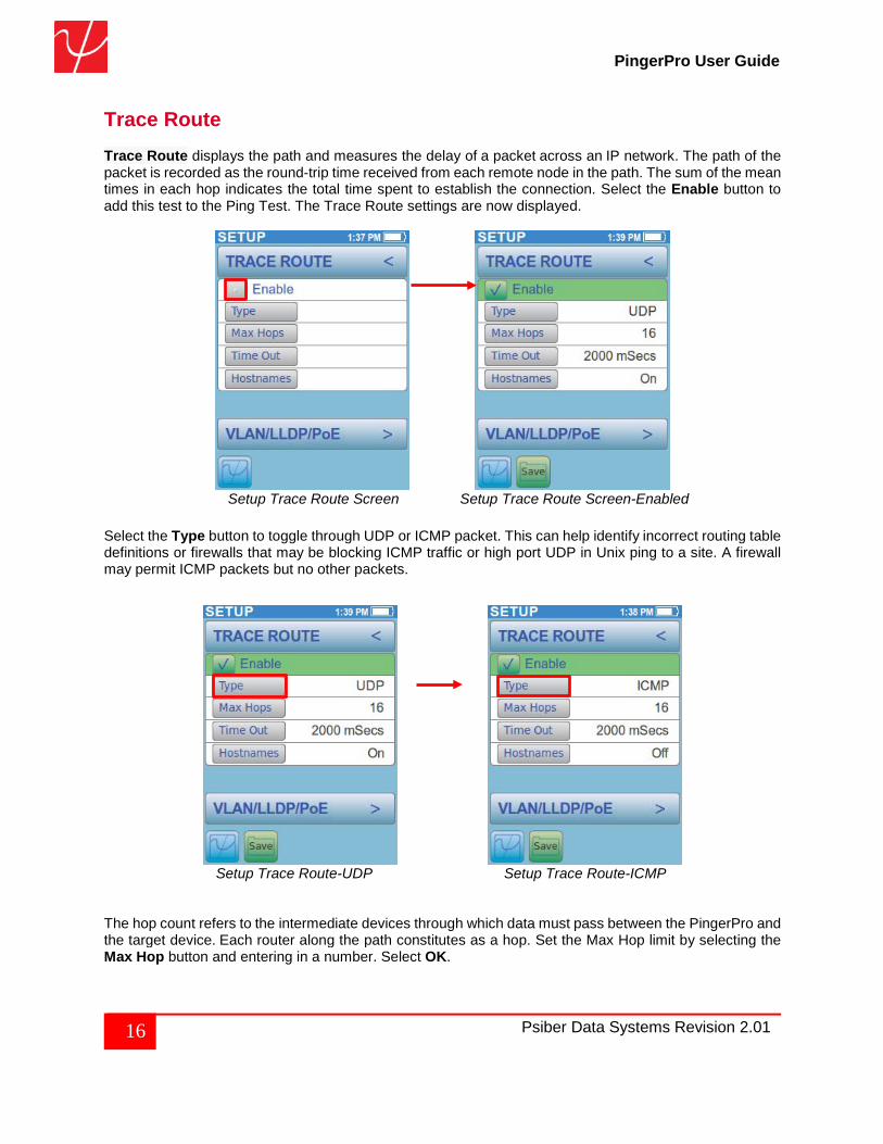
Trace Route Trace Route displays the path and measures the delay of a packet across an IP network. The path of the packet is recorded as the round-trip time received from each remote node in the path. The sum of the mean times in each hop indicates the total time spent to establish the connection. Select the Enable button to add this test to the Ping Test. The Trace Route settings are now displayed.
Setup Trace Route Screen Setup Trace Route Screen-Enabled
Select the Type button to toggle through UDP or ICMP packet. This can help identify incorrect routing table definitions or firewalls that may be blocking ICMP traffic or high port UDP in Unix ping to a site. A firewall may permit ICMP packets but no other packets.
Setup Trace Route-UDP Setup Trace Route-ICMP The hop count refers to the intermediate devices through which data must pass between the PingerPro and the target device. Each router along the path constitutes as a hop. Set the Max Hop limit by selecting the Max Hop button and entering in a number. Select OK.
17 Psiber Data Systems Revision 2.01
PingerPro User Guide
Timeout is the amount of time the PingerPro waits before a Trace Route packet returns. Hostnames toggles between Off and On. This allows for the device name to be displayed or just the IP address. Select the Save button to save the configuration.
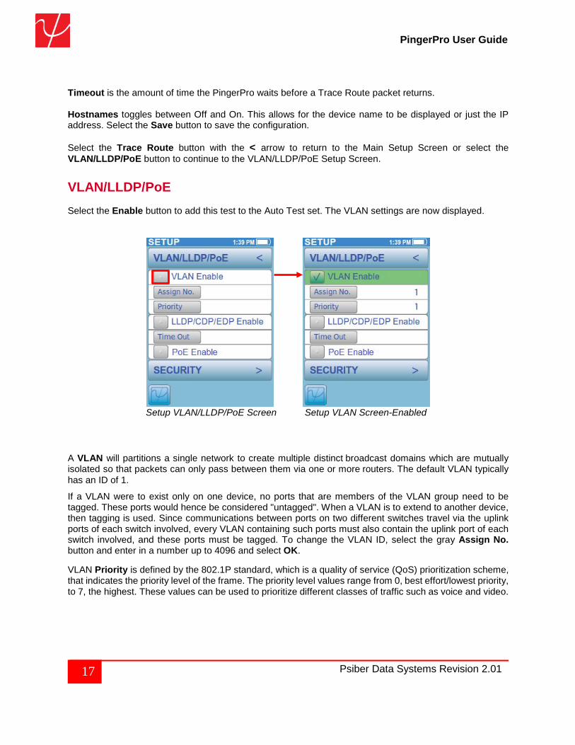
Select the Trace Route button with the < arrow to return to the Main Setup Screen or select the VLAN/LLDP/PoE button to continue to the VLAN/LLDP/PoE Setup Screen. VLAN/LLDP/PoE Select the Enable button to add this test to the Auto Test set. The VLAN settings are now displayed.
Setup VLAN/LLDP/PoE Screen Setup VLAN Screen-Enabled
A VLAN will partitions a single network to create multiple distinct broadcast domains which are mutually isolated so that packets can only pass between them via one or more routers. The default VLAN typically has an ID of 1.
If a VLAN were to exist only on one device, no ports that are members of the VLAN group need to be tagged. These ports would hence be considered "untagged". When a VLAN is to extend to another device, then tagging is used. Since communications between ports on two different switches travel via the uplink ports of each switch involved, every VLAN containing such ports must also contain the uplink port of each switch involved, and these ports must be tagged. To change the VLAN ID, select the gray Assign No. button and enter in a number up to 4096 and select OK.
VLAN Priority is defined by the 802.1P standard, which is a quality of service (QoS) prioritization scheme, that indicates the priority level of the frame. The priority level values range from 0, best effort/lowest priority, to 7, the highest. These values can be used to prioritize different classes of traffic such as voice and video.
18 Psiber Data Systems Revision 2.01
PingerPro User Guide
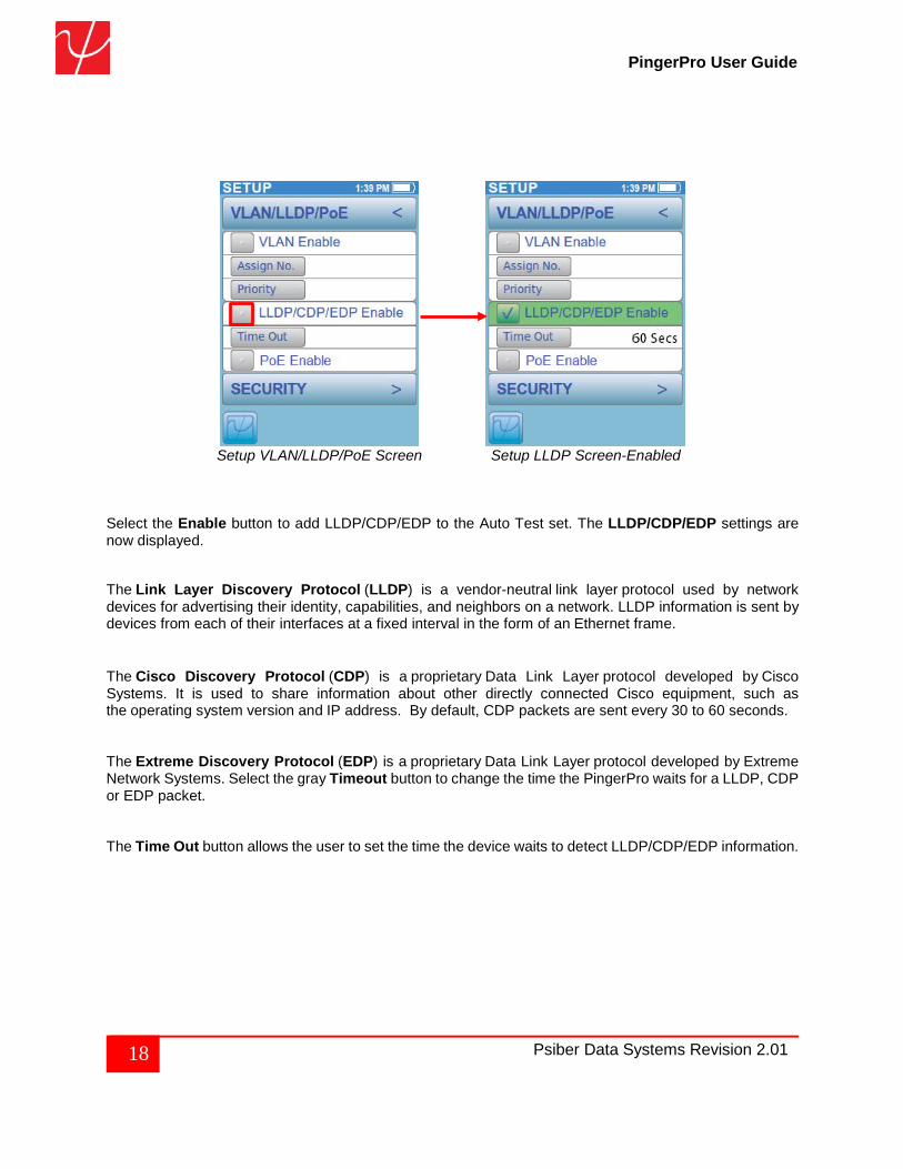
Setup VLAN/LLDP/PoE Screen Setup LLDP Screen-Enabled
Select the Enable button to add LLDP/CDP/EDP to the Auto Test set. The LLDP/CDP/EDP settings are now displayed. The Link Layer Discovery Protocol (LLDP) is a vendor-neutral link layer protocol used by network devices for advertising their identity, capabilities, and neighbors on a network. LLDP information is sent by devices from each of their interfaces at a fixed interval in the form of an Ethernet frame.
The Cisco Discovery Protocol (CDP) is a proprietary Data Link Layer protocol developed by Cisco Systems. It is used to share information about other directly connected Cisco equipment, such as the operating system version and IP address. By default, CDP packets are sent every 30 to 60 seconds. The Extreme Discovery Protocol (EDP) is a proprietary Data Link Layer protocol developed by Extreme Network Systems. Select the gray Timeout button to change the time the PingerPro waits for a LLDP, CDP or EDP packet. The Time Out button allows the user to set the time the device waits to detect LLDP/CDP/EDP information.
19 Psiber Data Systems Revision 2.01
PingerPro User Guide
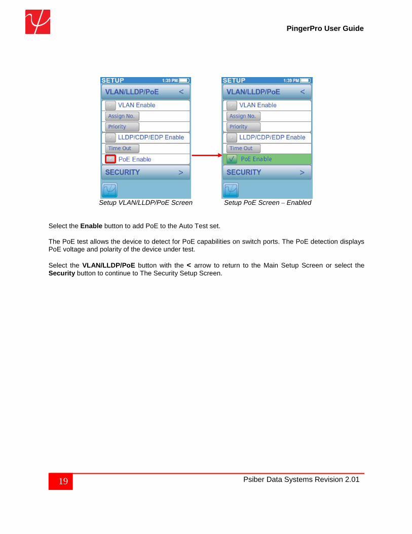
Setup VLAN/LLDP/PoE Screen Setup PoE Screen – Enabled
Select the Enable button to add PoE to the Auto Test set. The PoE test allows the device to detect for PoE capabilities on switch ports. The PoE detection displays PoE voltage and polarity of the device under test. Select the VLAN/LLDP/PoE button with the < arrow to return to the Main Setup Screen or select the Security button to continue to The Security Setup Screen.
20 Psiber Data Systems Revision 2.01
PingerPro User Guide
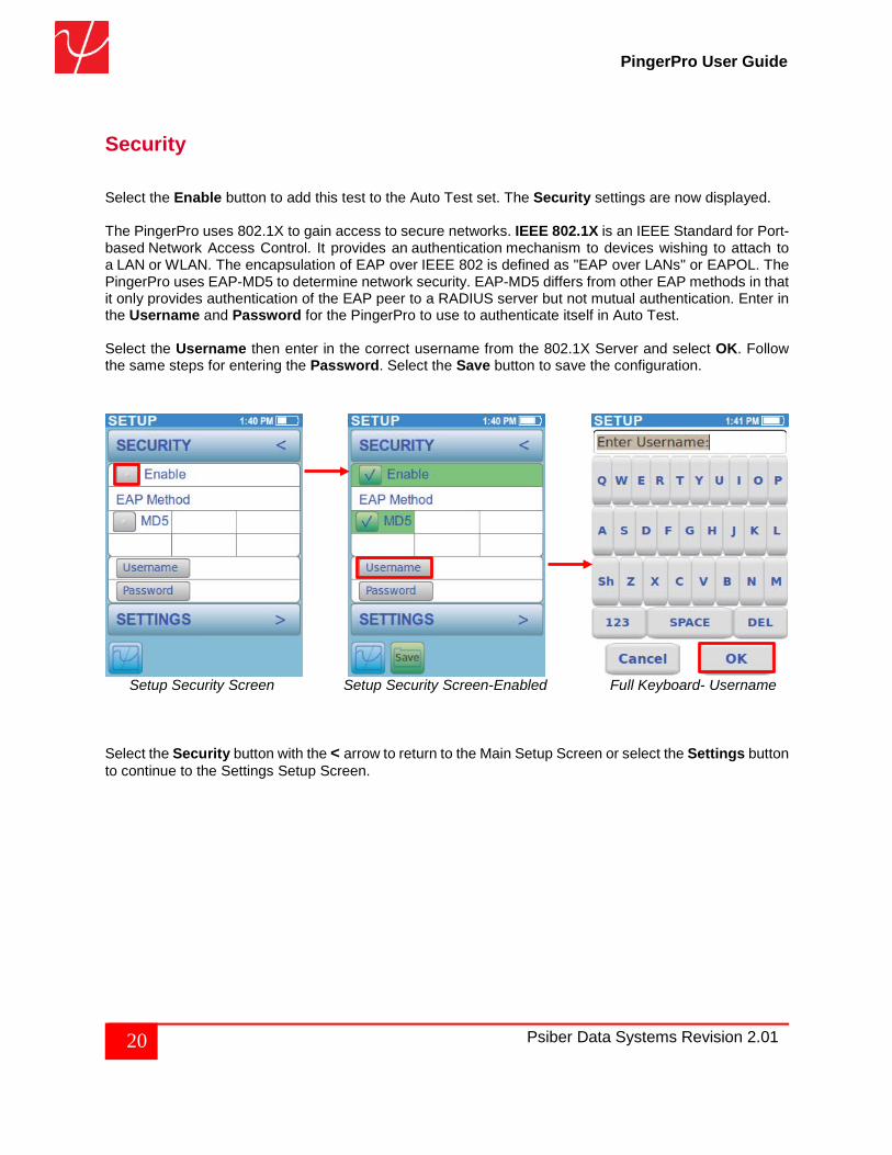
Security Select the Enable button to add this test to the Auto Test set. The Security settings are now displayed. The PingerPro uses 802.1X to gain access to secure networks. IEEE 802.1X is an IEEE Standard for Port-based Network Access Control. It provides an authentication mechanism to devices wishing to attach to a LAN or WLAN. The encapsulation of EAP over IEEE 802 is defined as "EAP over LANs" or EAPOL. The PingerPro uses EAP-MD5 to determine network security. EAP-MD5 differs from other EAP methods in that it only provides authentication of the EAP peer to a RADIUS server but not mutual authentication. Enter in the Username and Password for the PingerPro to use to authenticate itself in Auto Test. Select the Username then enter in the correct username from the 802.1X Server and select OK. Follow the same steps for entering the Password. Select the Save button to save the configuration.
Setup Security Screen Setup Security Screen-Enabled Full Keyboard- Username
Select the Security button with the < arrow to return to the Main Setup Screen or select the Settings button to continue to the Settings Setup Screen.
21 Psiber Data Systems Revision 2.01
PingerPro User Guide
Settings
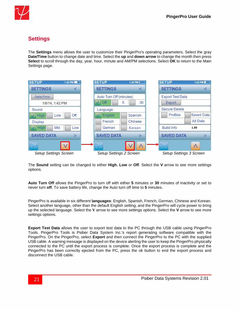
The Settings menu allows the user to customize their PingerPro's operating parameters. Select the gray Date/Time button to change date and time. Select the up and down arrow to change the month then press Select to scroll through the day, year, hour, minute and AM/PM selections. Select OK to return to the Main Settings page.
Setup Settings Screen Setup Settings 2 Screen Setup Settings 3 Screen The Sound setting can be changed to either High, Low or Off. Select the V arrow to see more settings options. Auto Turn Off allows the PingerPro to turn off with either 5 minutes or 30 minutes of inactivity or set to never turn off. To save battery life, change the Auto turn off time to 5 minutes. PingerPro is available in six different languages: English, Spanish, French, German, Chinese and Korean. Select another language, other than the default English setting, and the PingerPro will cycle power to bring up the selected language. Select the V arrow to see more settings options. Select the V arrow to see more settings options. Export Test Data allows the user to export test data to the PC through the USB cable using PingerPro Tools. PingerPro Tools is Psiber Data System Inc.'s report generating software compatible with the PingerPro. On the PingerPro, select Export and then connect the PingerPro to the PC with the supplied USB cable. A warning message is displayed on the device alerting the user to keep the PingerPro physically connected to the PC until the export process is complete. Once the export process is complete and the PingerPro has been correctly ejected from the PC, press the ok button to end the export process and disconnect the USB cable.
1.00
22 Psiber Data Systems Revision 2.01
PingerPro User Guide
Secure Delete allows the user to set the PingerPro back to the Factory Default settings. The user has the option to select Profiles, Saved Data or All data to be deleted. Please note that once this is selected there is no way of getting back the data. Build Info shows the latest firmware running on the PingerPro. Check the www.psiber.com website for the latest firmware. Select the Settings button with the < arrow to return to the Main Setup Screen or select the Saved Data button to continue to The Saved Data Setup Screen.
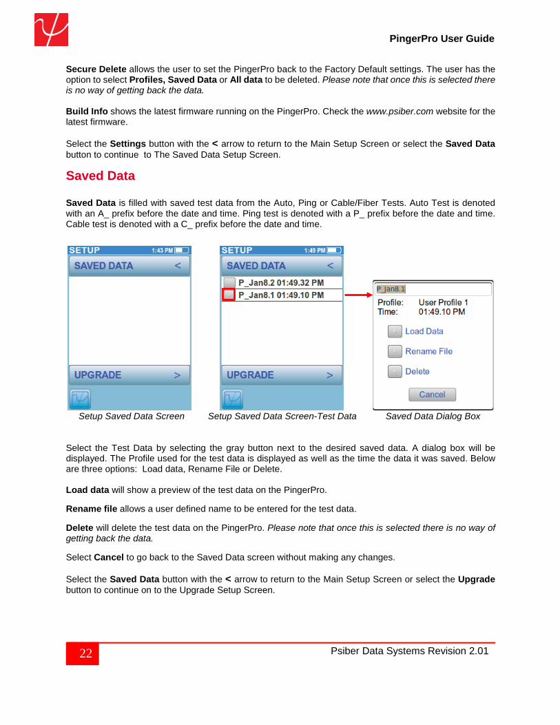
Saved Data Saved Data is filled with saved test data from the Auto, Ping or Cable/Fiber Tests. Auto Test is denoted with an A_ prefix before the date and time. Ping test is denoted with a P_ prefix before the date and time. Cable test is denoted with a C_ prefix before the date and time.
Setup Saved Data Screen Setup Saved Data Screen-Test Data Saved Data Dialog Box
Select the Test Data by selecting the gray button next to the desired saved data. A dialog box will be displayed. The Profile used for the test data is displayed as well as the time the data it was saved. Below are three options: Load data, Rename File or Delete. Load data will show a preview of the test data on the PingerPro. Rename file allows a user defined name to be entered for the test data.
Delete will delete the test data on the PingerPro. Please note that once this is selected there is no way of getting back the data. Select Cancel to go back to the Saved Data screen without making any changes. Select the Saved Data button with the < arrow to return to the Main Setup Screen or select the Upgrade button to continue on to the Upgrade Setup Screen.
23 Psiber Data Systems Revision 2.01
PingerPro User Guide
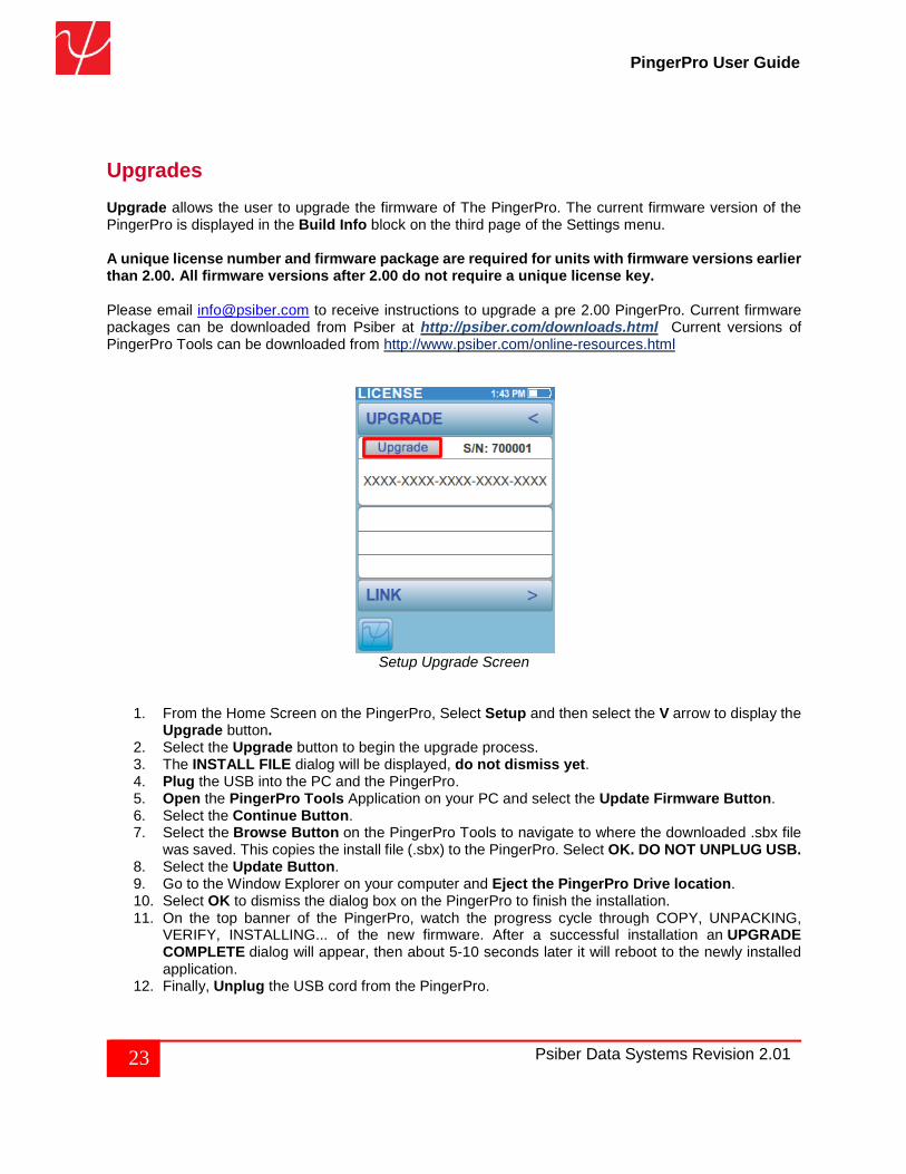
Upgrades Upgrade allows the user to upgrade the firmware of The PingerPro. The current firmware version of the PingerPro is displayed in the Build Info block on the third page of the Settings menu. A unique license number and firmware package are required for units with firmware versions earlier than 2.00. All firmware versions after 2.00 do not require a unique license key. Please email [email protected] to receive instructions to upgrade a pre 2.00 PingerPro. Current firmware packages can be downloaded from Psiber at http://psiber.com/downloads.html Current versions of PingerPro Tools can be downloaded from http://www.psiber.com/online-resources.html
Setup Upgrade Screen
1. From the Home Screen on the PingerPro, Select Setup and then select the V arrow to display the Upgrade button.
2. Select the Upgrade button to begin the upgrade process. 3. The INSTALL FILE dialog will be displayed, do not dismiss yet. 4. Plug the USB into the PC and the PingerPro. 5. Open the PingerPro Tools Application on your PC and select the Update Firmware Button. 6. Select the Continue Button. 7. Select the Browse Button on the PingerPro Tools to navigate to where the downloaded .sbx file
was saved. This copies the install file (.sbx) to the PingerPro. Select OK. DO NOT UNPLUG USB. 8. Select the Update Button. 9. Go to the Window Explorer on your computer and Eject the PingerPro Drive location. 10. Select OK to dismiss the dialog box on the PingerPro to finish the installation. 11. On the top banner of the PingerPro, watch the progress cycle through COPY, UNPACKING,
VERIFY, INSTALLING... of the new firmware. After a successful installation an UPGRADE COMPLETE dialog will appear, then about 5-10 seconds later it will reboot to the newly installed application.
12. Finally, Unplug the USB cord from the PingerPro.
24 Psiber Data Systems Revision 2.01
PingerPro User Guide
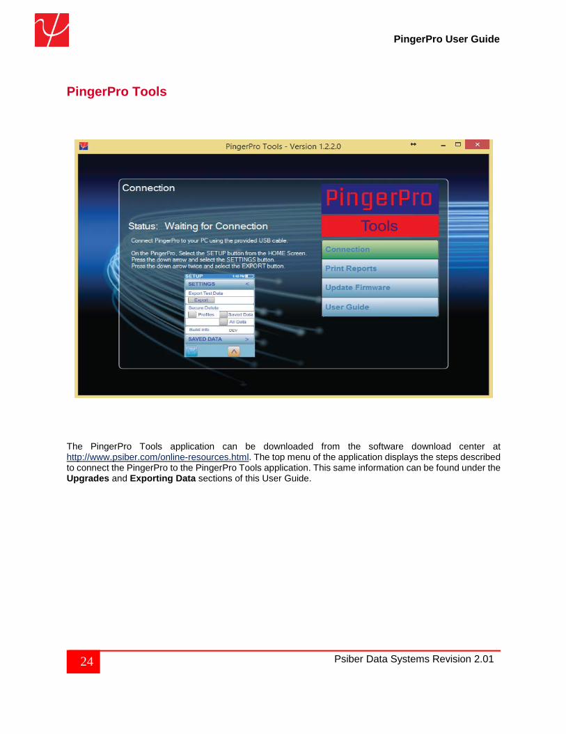
PingerPro Tools
The PingerPro Tools application can be downloaded from the software download center at http://www.psiber.com/online-resources.html. The top menu of the application displays the steps described to connect the PingerPro to the PingerPro Tools application. This same information can be found under the Upgrades and Exporting Data sections of this User Guide.
25 Psiber Data Systems Revision 2.01
PingerPro User Guide
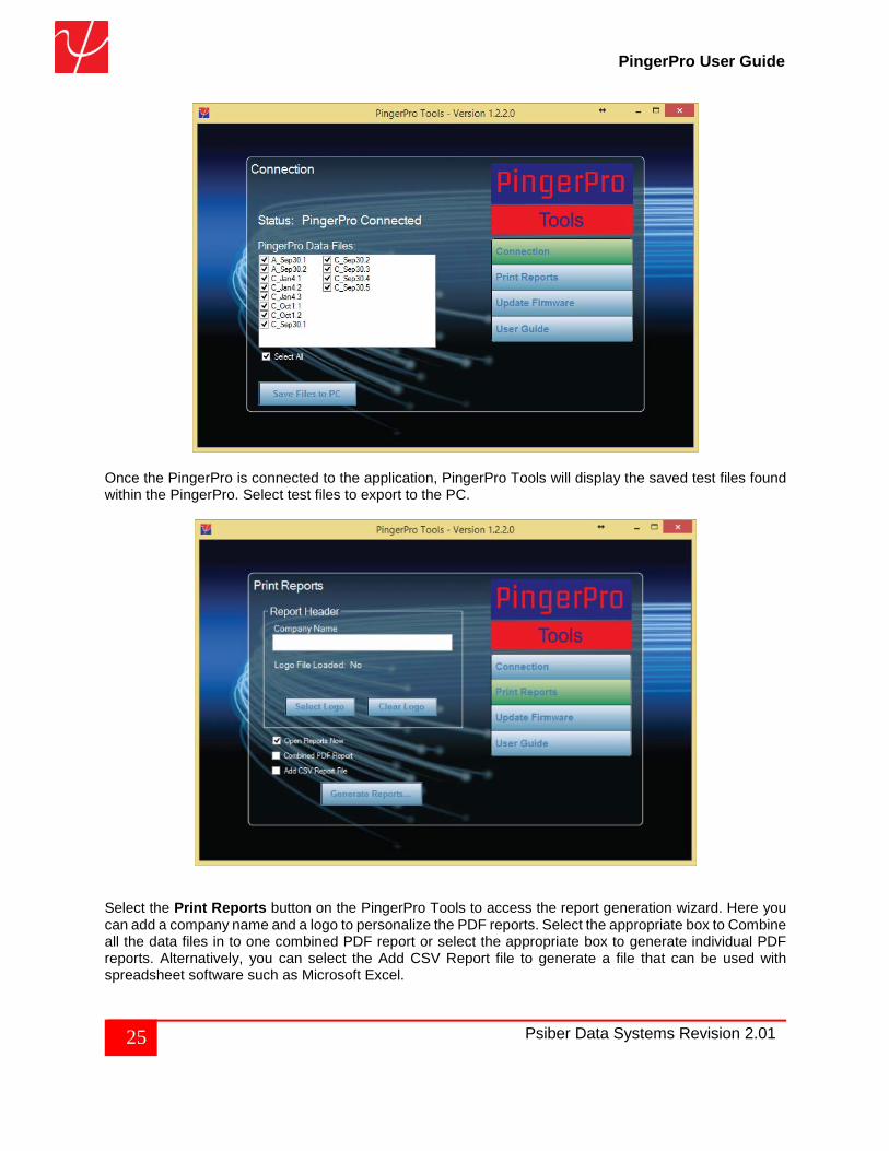
Once the PingerPro is connected to the application, PingerPro Tools will display the saved test files found within the PingerPro. Select test files to export to the PC.
Select the Print Reports button on the PingerPro Tools to access the report generation wizard. Here you can add a company name and a logo to personalize the PDF reports. Select the appropriate box to Combine all the data files in to one combined PDF report or select the appropriate box to generate individual PDF reports. Alternatively, you can select the Add CSV Report file to generate a file that can be used with spreadsheet software such as Microsoft Excel.
26 Psiber Data Systems Revision 2.01
PingerPro User Guide
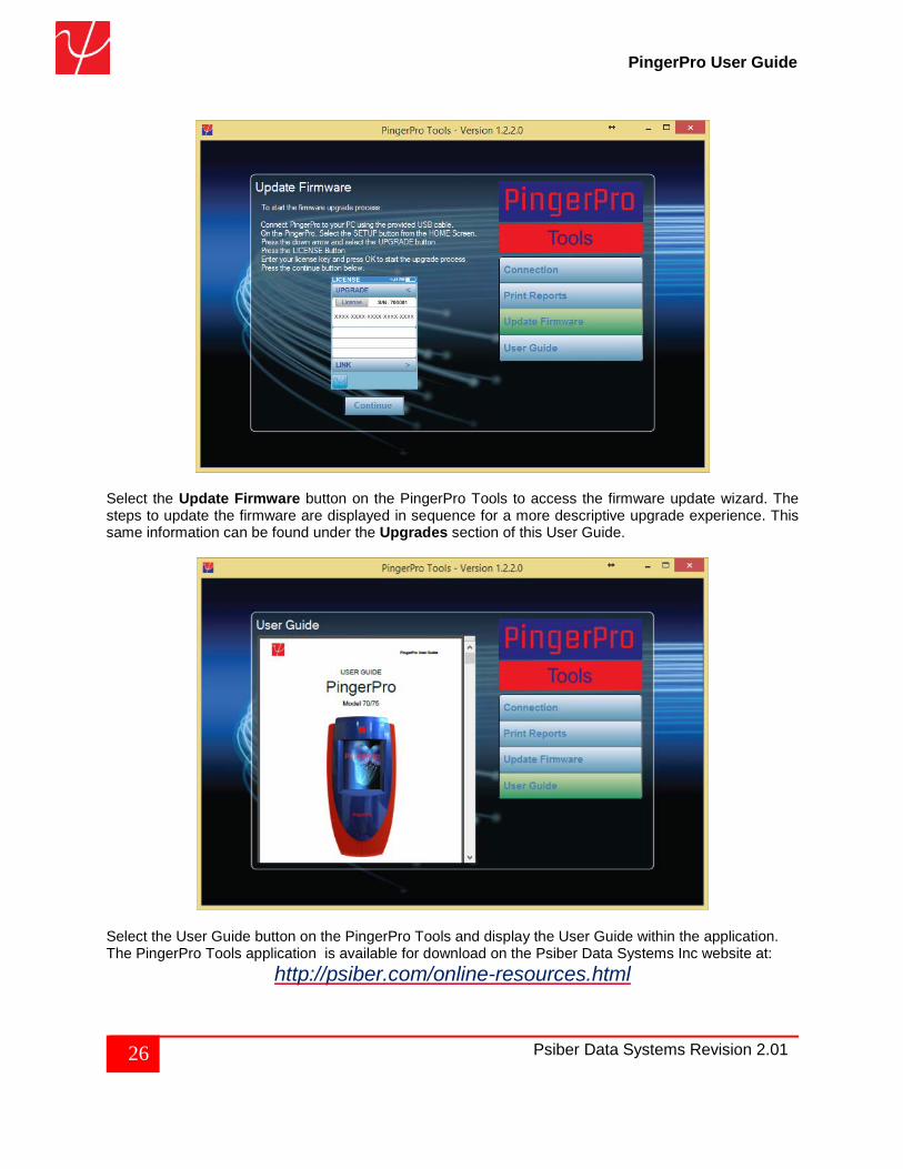
Select the Update Firmware button on the PingerPro Tools to access the firmware update wizard. The steps to update the firmware are displayed in sequence for a more descriptive upgrade experience. This same information can be found under the Upgrades section of this User Guide.
Select the User Guide button on the PingerPro Tools and display the User Guide within the application. The PingerPro Tools application is available for download on the Psiber Data Systems Inc website at:
http://psiber.com/online-resources.html
27 Psiber Data Systems Revision 2.01
PingerPro User Guide
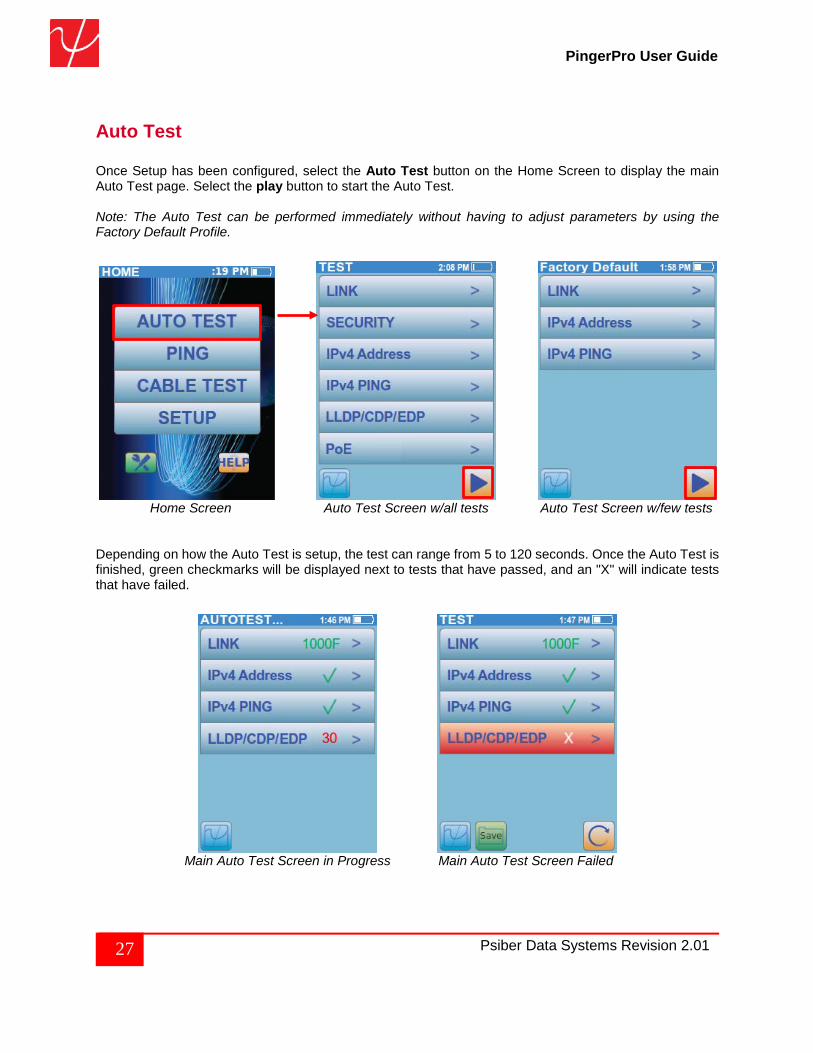
Auto Test Once Setup has been configured, select the Auto Test button on the Home Screen to display the main Auto Test page. Select the play button to start the Auto Test. Note: The Auto Test can be performed immediately without having to adjust parameters by using the Factory Default Profile.
Home Screen Auto Test Screen w/all tests Auto Test Screen w/few tests
Depending on how the Auto Test is setup, the test can range from 5 to 120 seconds. Once the Auto Test is finished, green checkmarks will be displayed next to tests that have passed, and an "X" will indicate tests that have failed.
Main Auto Test Screen in Progress Main Auto Test Screen Failed
28 Psiber Data Systems Revision 2.01
PingerPro User Guide
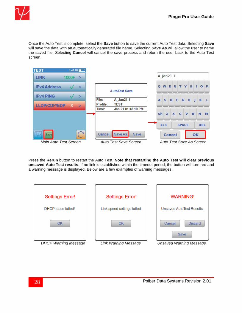
Once the Auto Test is complete, select the Save button to save the current Auto Test data. Selecting Save will save the data with an automatically generated file name. Selecting Save As will allow the user to name the saved file. Selecting Cancel will cancel the save process and return the user back to the Auto Test screen.
Main Auto Test Screen Auto Test Save Screen Auto Test Save As Screen
Press the Rerun button to restart the Auto Test. Note that restarting the Auto Test will clear previous unsaved Auto Test results. If no link is established within the timeout period, the button will turn red and a warning message is displayed. Below are a few examples of warning messages.
DHCP Warning Message Link Warning Message Unsaved Warning Message
29 Psiber Data Systems Revision 2.01
PingerPro User Guide
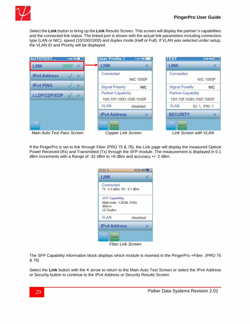
Select the Link button to bring up the Link Results Screen. This screen will display the partner’s capabilities and the connected link status. The linked port is shown with the actual link parameters including connection type (LAN or NIC), speed (10/100/1000) and duplex mode (Half or Full). If VLAN was selected under setup, the VLAN ID and Priority will be displayed.
Main Auto Test Pass Screen Copper Link Screen Link Screen with VLAN If the PingerPro is set to link through Fiber (PRO 75 & 76), the Link page will display the measured Optical Power Received (Rx) and Transmitted (Tx) through the SFP module. The measurement is displayed in 0.1 dBm increments with a Range of -32 dBm to +8 dBm and accuracy +/- 2 dBm.
Fiber Link Screen
The SFP Capability information block displays which module is inserted in the PingerPro +Fiber. (PRO 75 & 76) Select the Link button with the < arrow to return to the Main Auto Test Screen or select the IPv4 Address or Security button to continue to the IPv4 Address or Security Results Screen.
30 Psiber Data Systems Revision 2.01
PingerPro User Guide
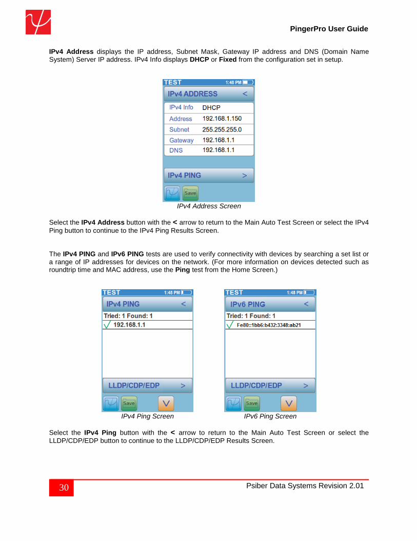
IPv4 Address displays the IP address, Subnet Mask, Gateway IP address and DNS (Domain Name System) Server IP address. IPv4 Info displays DHCP or Fixed from the configuration set in setup.
IPv4 Address Screen
Select the IPv4 Address button with the < arrow to return to the Main Auto Test Screen or select the IPv4 Ping button to continue to the IPv4 Ping Results Screen.
The IPv4 PING and IPv6 PING tests are used to verify connectivity with devices by searching a set list or a range of IP addresses for devices on the network. (For more information on devices detected such as roundtrip time and MAC address, use the Ping test from the Home Screen.)
IPv4 Ping Screen IPv6 Ping Screen
Select the IPv4 Ping button with the < arrow to return to the Main Auto Test Screen or select the LLDP/CDP/EDP button to continue to the LLDP/CDP/EDP Results Screen.
31 Psiber Data Systems Revision 2.01
PingerPro User Guide
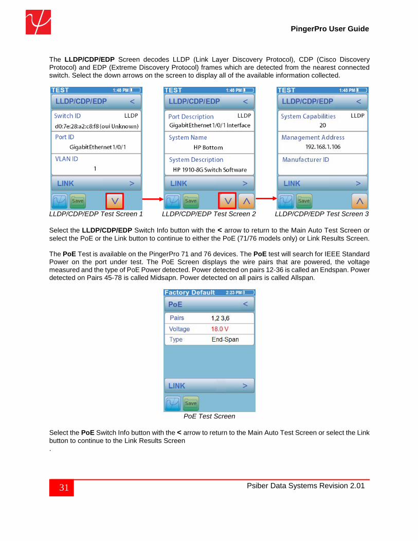
The LLDP/CDP/EDP Screen decodes LLDP (Link Layer Discovery Protocol), CDP (Cisco Discovery Protocol) and EDP (Extreme Discovery Protocol) frames which are detected from the nearest connected switch. Select the down arrows on the screen to display all of the available information collected.
LLDP/CDP/EDP Test Screen 1 LLDP/CDP/EDP Test Screen 2 LLDP/CDP/EDP Test Screen 3
Select the LLDP/CDP/EDP Switch Info button with the < arrow to return to the Main Auto Test Screen or select the PoE or the Link button to continue to either the PoE (71/76 models only) or Link Results Screen. The PoE Test is available on the PingerPro 71 and 76 devices. The PoE test will search for IEEE Standard Power on the port under test. The PoE Screen displays the wire pairs that are powered, the voltage measured and the type of PoE Power detected. Power detected on pairs 12-36 is called an Endspan. Power detected on Pairs 45-78 is called Midsapn. Power detected on all pairs is called Allspan.
PoE Test Screen
Select the PoE Switch Info button with the < arrow to return to the Main Auto Test Screen or select the Link button to continue to the Link Results Screen .
32 Psiber Data Systems Revision 2.01
PingerPro User Guide
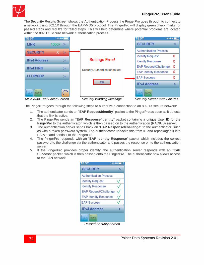
The Security Results Screen shows the Authentication Process the PingerPro goes through to connect to a network using 802.1X through the EAP-MD5 protocol. The PingerPro will display green check marks for passed steps and red X's for failed steps. This will help determine where potential problems are located within the 802.1X Secure network authentication process.
Main Auto Test Failed Screen Security Warning Message Security Screen with Failures
The PingerPro goes through the following steps to authorize a connection to an 802.1X secure network:
1. The authenticator sends an "EAP Request/Identity" packet to the PingerPro as soon as it detects that the link is active.
2. The PingerPro sends an "EAP Response/Identity" packet containing a unique User ID for the PingerPro to the authenticator, which is then passed on to the authentication (RADIUS) server.
3. The authentication server sends back an “EAP Response/challenge” to the authenticator, such as with a token password system. The authenticator unpacks this from IP and repackages it into EAPOL and sends it to the PingerPro.
4. The PingerPro responds with an “EAP Identity Response” packet which includes the correct password to the challenge via the authenticator and passes the response on to the authentication server.
5. If the PingerPro provides proper identity, the authentication server responds with an “EAP Success” packet, which is then passed onto the PingerPro. The authenticator now allows access to the LAN network.
Passed Security Screen
33 Psiber Data Systems Revision 2.01
PingerPro User Guide
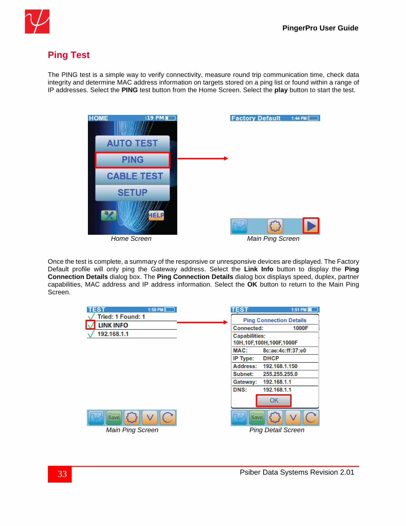
Ping Test The PING test is a simple way to verify connectivity, measure round trip communication time, check data integrity and determine MAC address information on targets stored on a ping list or found within a range of IP addresses. Select the PING test button from the Home Screen. Select the play button to start the test.
Home Screen Main Ping Screen
Once the test is complete, a summary of the responsive or unresponsive devices are displayed. The Factory Default profile will only ping the Gateway address. Select the Link Info button to display the Ping Connection Details dialog box. The Ping Connection Details dialog box displays speed, duplex, partner capabilities, MAC address and IP address information. Select the OK button to return to the Main Ping Screen.
Main Ping Screen Ping Detail Screen
34 Psiber Data Systems Revision 2.01
PingerPro User Guide
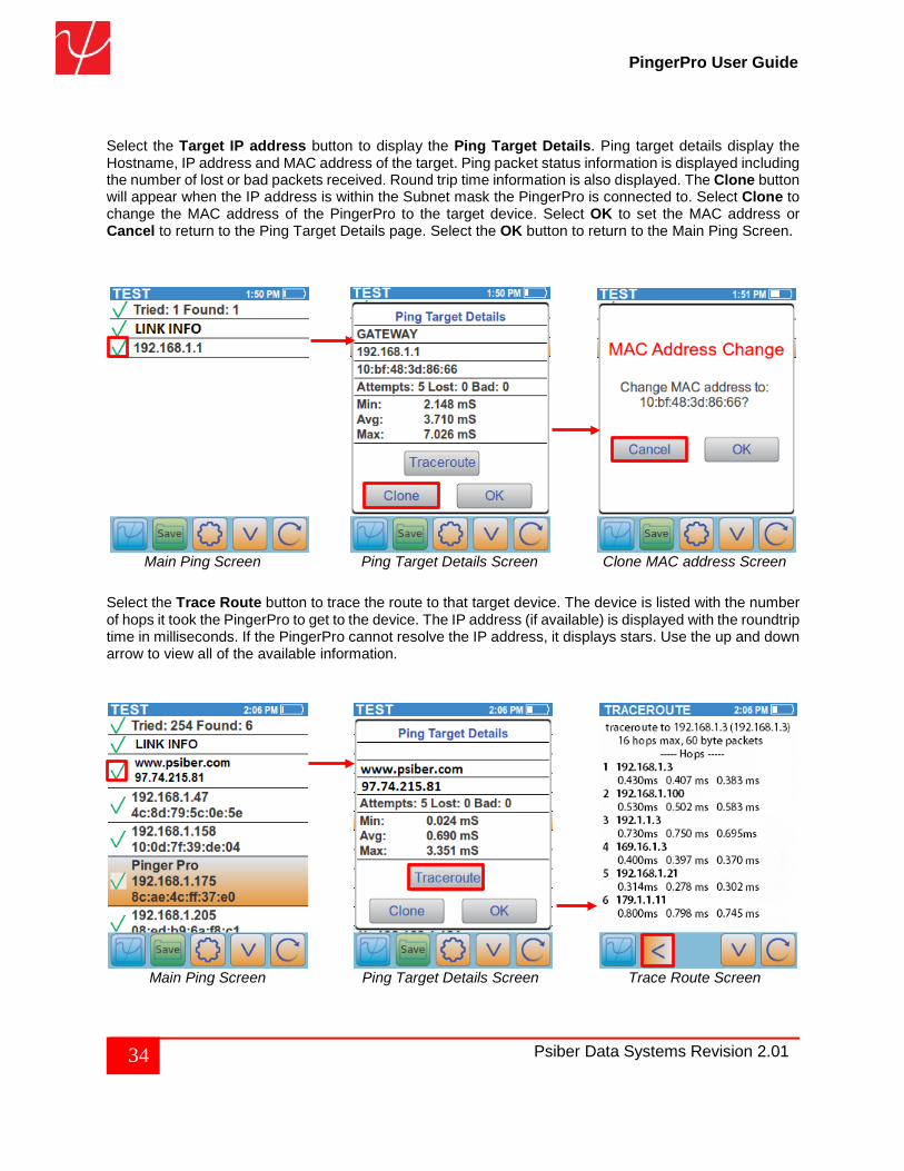
Select the Target IP address button to display the Ping Target Details. Ping target details display the Hostname, IP address and MAC address of the target. Ping packet status information is displayed including the number of lost or bad packets received. Round trip time information is also displayed. The Clone button will appear when the IP address is within the Subnet mask the PingerPro is connected to. Select Clone to change the MAC address of the PingerPro to the target device. Select OK to set the MAC address or Cancel to return to the Ping Target Details page. Select the OK button to return to the Main Ping Screen.
Main Ping Screen Ping Target Details Screen Clone MAC address Screen
Select the Trace Route button to trace the route to that target device. The device is listed with the number of hops it took the PingerPro to get to the device. The IP address (if available) is displayed with the roundtrip time in milliseconds. If the PingerPro cannot resolve the IP address, it displays stars. Use the up and down arrow to view all of the available information.
Main Ping Screen Ping Target Details Screen Trace Route Screen
35 Psiber Data Systems Revision 2.01
PingerPro User Guide
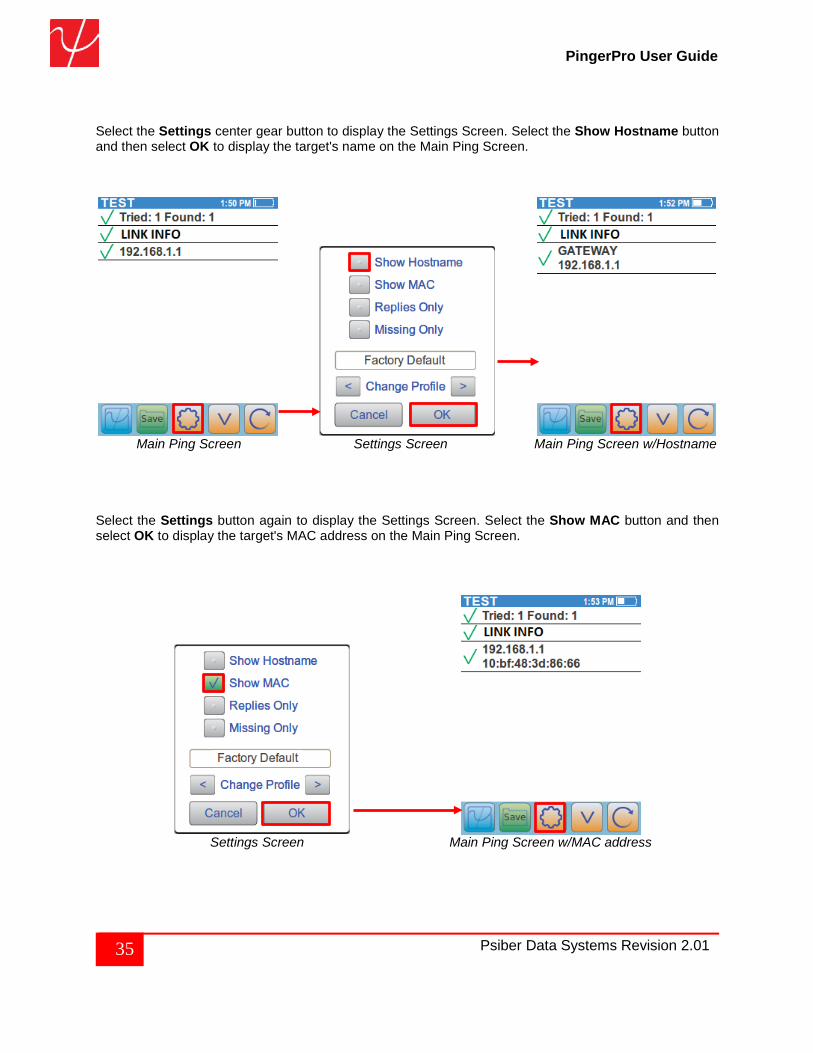
Select the Settings center gear button to display the Settings Screen. Select the Show Hostname button and then select OK to display the target's name on the Main Ping Screen.
Main Ping Screen Settings Screen Main Ping Screen w/Hostname Select the Settings button again to display the Settings Screen. Select the Show MAC button and then select OK to display the target's MAC address on the Main Ping Screen.
Settings Screen Main Ping Screen w/MAC address
36 Psiber Data Systems Revision 2.01
PingerPro User Guide
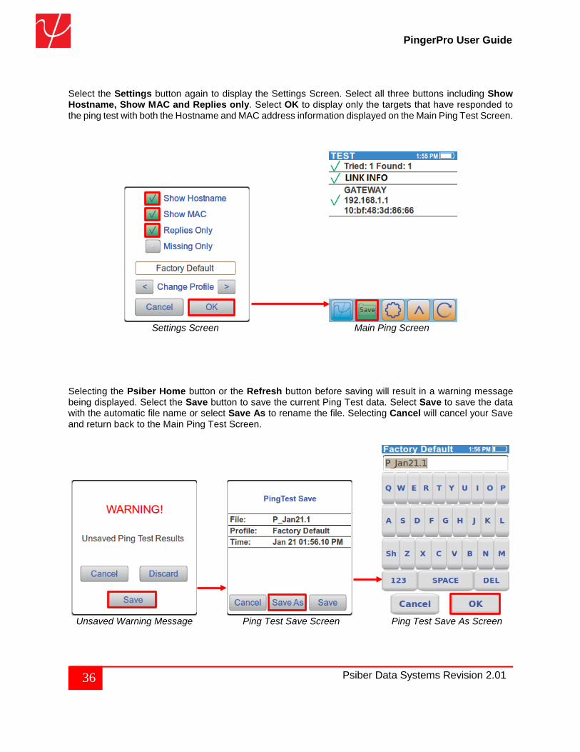
Select the Settings button again to display the Settings Screen. Select all three buttons including Show Hostname, Show MAC and Replies only. Select OK to display only the targets that have responded to the ping test with both the Hostname and MAC address information displayed on the Main Ping Test Screen.
Settings Screen Main Ping Screen
Selecting the Psiber Home button or the Refresh button before saving will result in a warning message being displayed. Select the Save button to save the current Ping Test data. Select Save to save the data with the automatic file name or select Save As to rename the file. Selecting Cancel will cancel your Save and return back to the Main Ping Test Screen.
Unsaved Warning Message Ping Test Save Screen Ping Test Save As Screen
37 Psiber Data Systems Revision 2.01
PingerPro User Guide
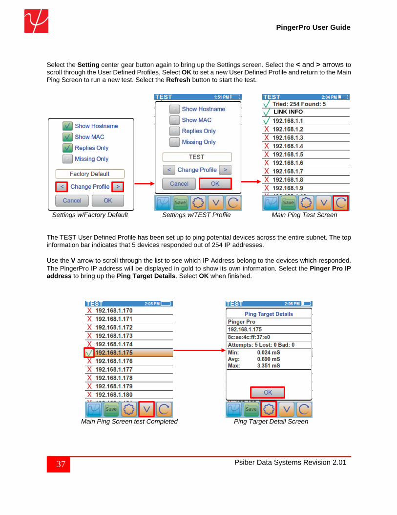
Select the Setting center gear button again to bring up the Settings screen. Select the < and > arrows to scroll through the User Defined Profiles. Select OK to set a new User Defined Profile and return to the Main Ping Screen to run a new test. Select the Refresh button to start the test.
Settings w/Factory Default Settings w/TEST Profile Main Ping Test Screen The TEST User Defined Profile has been set up to ping potential devices across the entire subnet. The top information bar indicates that 5 devices responded out of 254 IP addresses. Use the V arrow to scroll through the list to see which IP Address belong to the devices which responded. The PingerPro IP address will be displayed in gold to show its own information. Select the Pinger Pro IP address to bring up the Ping Target Details. Select OK when finished.
Main Ping Screen test Completed Ping Target Detail Screen
LINK INFO
38 Psiber Data Systems Revision 2.01
PingerPro User Guide
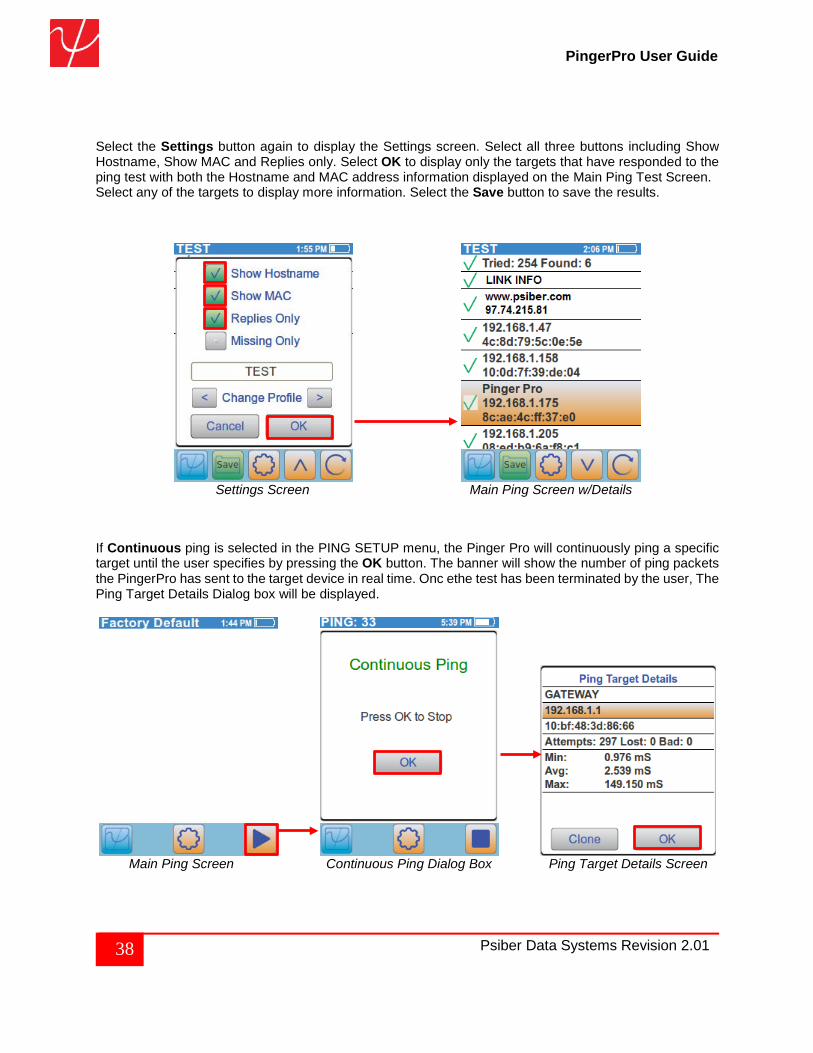
Select the Settings button again to display the Settings screen. Select all three buttons including Show Hostname, Show MAC and Replies only. Select OK to display only the targets that have responded to the ping test with both the Hostname and MAC address information displayed on the Main Ping Test Screen. Select any of the targets to display more information. Select the Save button to save the results.
Settings Screen Main Ping Screen w/Details
If Continuous ping is selected in the PING SETUP menu, the Pinger Pro will continuously ping a specific target until the user specifies by pressing the OK button. The banner will show the number of ping packets the PingerPro has sent to the target device in real time. Onc ethe test has been terminated by the user, The Ping Target Details Dialog box will be displayed.
Main Ping Screen Continuous Ping Dialog Box Ping Target Details Screen
39 Psiber Data Systems Revision 2.01
PingerPro User Guide
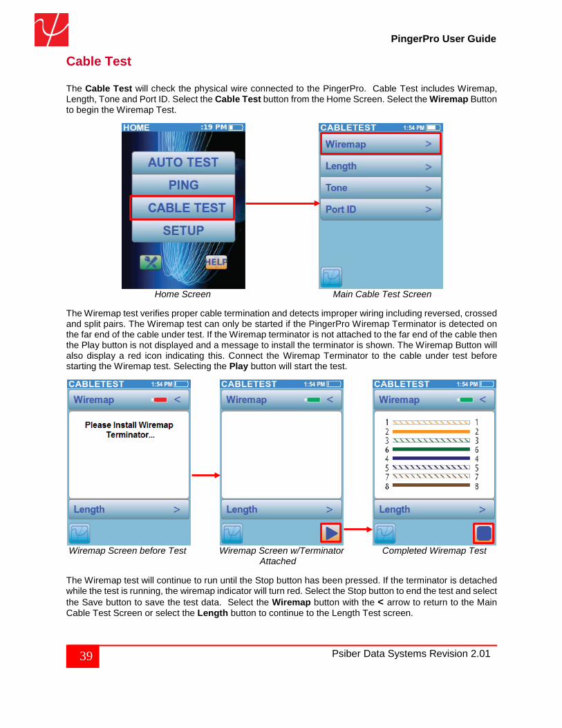
Cable Test The Cable Test will check the physical wire connected to the PingerPro. Cable Test includes Wiremap, Length, Tone and Port ID. Select the Cable Test button from the Home Screen. Select the Wiremap Button to begin the Wiremap Test.
Home Screen Main Cable Test Screen
The Wiremap test verifies proper cable termination and detects improper wiring including reversed, crossed and split pairs. The Wiremap test can only be started if the PingerPro Wiremap Terminator is detected on the far end of the cable under test. If the Wiremap terminator is not attached to the far end of the cable then the Play button is not displayed and a message to install the terminator is shown. The Wiremap Button will also display a red icon indicating this. Connect the Wiremap Terminator to the cable under test before starting the Wiremap test. Selecting the Play button will start the test.
Wiremap Screen before Test Wiremap Screen w/Terminator Completed Wiremap Test Attached The Wiremap test will continue to run until the Stop button has been pressed. If the terminator is detached while the test is running, the wiremap indicator will turn red. Select the Stop button to end the test and select the Save button to save the test data. Select the Wiremap button with the < arrow to return to the Main Cable Test Screen or select the Length button to continue to the Length Test screen.
40 Psiber Data Systems Revision 2.01
PingerPro User Guide
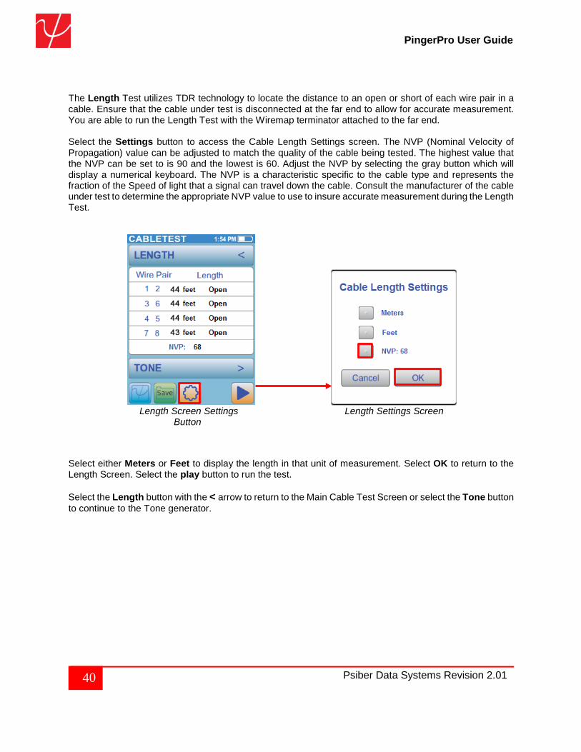
The Length Test utilizes TDR technology to locate the distance to an open or short of each wire pair in a cable. Ensure that the cable under test is disconnected at the far end to allow for accurate measurement. You are able to run the Length Test with the Wiremap terminator attached to the far end. Select the Settings button to access the Cable Length Settings screen. The NVP (Nominal Velocity of Propagation) value can be adjusted to match the quality of the cable being tested. The highest value that the NVP can be set to is 90 and the lowest is 60. Adjust the NVP by selecting the gray button which will display a numerical keyboard. The NVP is a characteristic specific to the cable type and represents the fraction of the Speed of light that a signal can travel down the cable. Consult the manufacturer of the cable under test to determine the appropriate NVP value to use to insure accurate measurement during the Length Test.
Length Screen Settings Length Settings Screen Button
Select either Meters or Feet to display the length in that unit of measurement. Select OK to return to the Length Screen. Select the play button to run the test. Select the Length button with the < arrow to return to the Main Cable Test Screen or select the Tone button to continue to the Tone generator.
41 Psiber Data Systems Revision 2.01
PingerPro User Guide
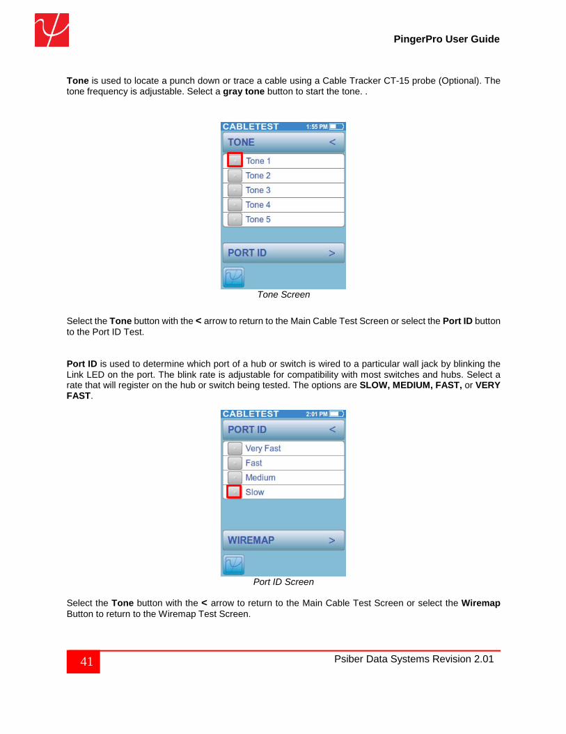
Tone is used to locate a punch down or trace a cable using a Cable Tracker CT-15 probe (Optional). The tone frequency is adjustable. Select a gray tone button to start the tone. .
Tone Screen
Select the Tone button with the < arrow to return to the Main Cable Test Screen or select the Port ID button to the Port ID Test. Port ID is used to determine which port of a hub or switch is wired to a particular wall jack by blinking the Link LED on the port. The blink rate is adjustable for compatibility with most switches and hubs. Select a rate that will register on the hub or switch being tested. The options are SLOW, MEDIUM, FAST, or VERY FAST.
Port ID Screen
Select the Tone button with the < arrow to return to the Main Cable Test Screen or select the Wiremap Button to return to the Wiremap Test Screen.
42 Psiber Data Systems Revision 2.01
PingerPro User Guide
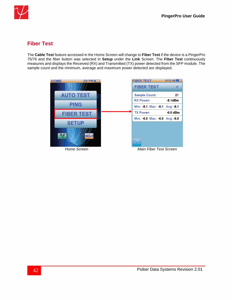
Fiber Test The Cable Test feature accessed in the Home Screen will change to Fiber Test if the device is a PingerPro 75/76 and the fiber button was selected in Setup under the Link Screen. The Fiber Test continuously measures and displays the Received (RX) and Transmitted (TX) power detected from the SFP module. The sample count and the minimum, average and maximum power detected are displayed.
Home Screen Main Fiber Test Screen
43 Psiber Data Systems Revision 2.01
PingerPro User Guide
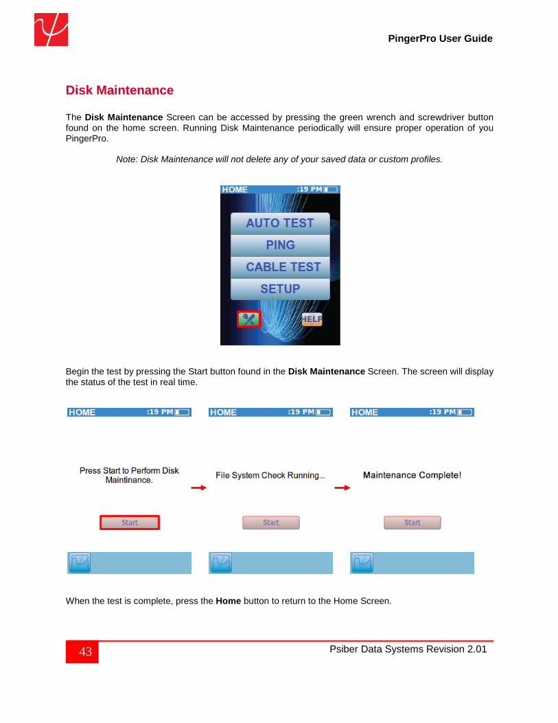
Disk Maintenance The Disk Maintenance Screen can be accessed by pressing the green wrench and screwdriver button found on the home screen. Running Disk Maintenance periodically will ensure proper operation of you PingerPro.
Note: Disk Maintenance will not delete any of your saved data or custom profiles.
Begin the test by pressing the Start button found in the Disk Maintenance Screen. The screen will display the status of the test in real time.
When the test is complete, press the Home button to return to the Home Screen.
44 Psiber Data Systems Revision 2.01
PingerPro User Guide
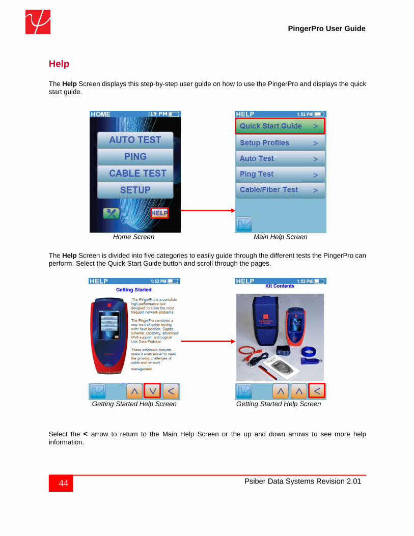
Help The Help Screen displays this step-by-step user guide on how to use the PingerPro and displays the quick start guide.
Home Screen Main Help Screen
The Help Screen is divided into five categories to easily guide through the different tests the PingerPro can perform. Select the Quick Start Guide button and scroll through the pages.
Getting Started Help Screen Getting Started Help Screen Select the < arrow to return to the Main Help Screen or the up and down arrows to see more help information.