Embed Size (px)
Citation preview

SlimLine Compressed Air DryerModels 2.5, 5, 15, 25 and 50
Corporate Office: 412.312.6000 l Instant Access 24/7 (Parts and Service): 800.458.1960 l Parts and Service: 814.437.6861
U S E R G U I D E
UGD039-1006
www.conairnet.com
INTRODUCTION • Purpose of the User Guide • How the guide is organized • Your responsibilities as a user • ATTENTION:
Read this so no one gets hurt • DESCRIPTION • What is the SlimLine - Compressed air dryer ? • Typical applica-
tions • How it works: The SlimLine • How it works: Typical plant compressed air system • Specifications: SlimLine •
INSTALLATION • Unpacking the boxes • Preparing for installation • Mounting the hopper/dryer onto a processing
machine • Mounting a loader on the hopper • Mounting an optional hand-fill lid, models SL15, SL25, SL50 • Connecting
the main power • Connecting a compressed air supply • Installing the optional slide gate • Installing the optional mount-
ing adapter with drain • OPERATION • The SlimLine control panel • Loading material into the hopper • Adjusting the
pressure regulator • To start drying • To stop drying • Setting the high alarm setpoint • Changing the temperature units
(fahrenheit/celsius) • Using the optional slide gate • Using the optional mounting adapter with drain • MAINTENANCE
SL15SL25
SL50
SL2.5
SL5
Please record your equipment’smodel and serial number(s) andthe date you received it in thespaces provided.
It’s a good idea to record the model and serial number(s) of your equipment andthe date you received it in the User Guide. Our service department uses this infor-mation, along with the manual number, to provide help for the specific equipmentyou installed.
Please keep this User Guide and all manuals, engineering prints and parts liststogether for documentation of your equipment.
Date:
Manual Number: UGD039-1006
Serial Number(s):
Model Number(s):
DISCLAIMER: The Conair Group, Inc., shall not be liable for errors contained in this User Guide orfor incidental, consequential damages in connection with the furnishing, performance or use ofthis information. Conair makes no warranty of any kind with regard to this information, including,but not limited to the implied warranties of merchantability and fitness for a particular purpose.
Copy r i gh t 2006 l The Cona i r G roup l A l l r i gh t s r ese r ved
Tab le o f Conten ts
1-1 I n t r oduc t i on
Purpose of the user guide . . . . . . . . . . . . . . . . . . . . . . . . . . . . . . . . 1-2
How the guide is organized . . . . . . . . . . . . . . . . . . . . . . . . . . . . . . 1-2
Your responsibilities as a user . . . . . . . . . . . . . . . . . . . . . . . . . . . . . 1-3
ATTENTION: Read this so no one gets hurt . . . . . . . . . . . . . . . . . . . 1-4
2-1 Desc r i p t i onWhat is the SlimLine - Compressed Air Dryer?. . . . . . . . . . . . . . . . .2-2
Typical applications . . . . . . . . . . . . . . . . . . . . . . . . . . . . . . . . . . . . .2-2
How it works: The SlimLine . . . . . . . . . . . . . . . . . . . . . . . . . . . . . . .2-3
How it works: Typical Plant Compressed Air System. . . . . . . . . . . . .2-4
Specifications: SlimLine . . . . . . . . . . . . . . . . . . . . . . . . . . . . . . . . . 2-5
Application data: SlimLine . . . . . . . . . . . . . . . . . . . . . . . . . . . . . . . . 2-5
3-1 I n s t a l l a t i onUnpacking the boxes . . . . . . . . . . . . . . . . . . . . . . . . . . . . . . . . . . . 3-2
Preparing for installation . . . . . . . . . . . . . . . . . . . . . . . . . . . . . . . . . 3-3
Lifting the dryer (models SL25 and 50) . . . . . . . . . . . . . . . . . . . . . . 3-4
Mounting the hopper/dryer unit. . . . . . . . . . . . . . . . . . . . . . . . . . . . 3-5
Mounting a loader onto the hopper . . . . . . . . . . . . . . . . . . . . . . . . . 3-6
Mounting a hand-fill lid (optional) on models SL15, SL25, SL50 . . . 3-7
Connecting the main power . . . . . . . . . . . . . . . . . . . . . . . . . . . . . . 3-7
Connecting a compressed air supply. . . . . . . . . . . . . . . . . . . . . . . . 3-8
Tab le o f Con ten t s l i
4-1 Opera t i onThe SlimLine control panel . . . . . . . . . . . . . . . . . . . . . . . . . . . . . . . 4-2
Loading material into the hopper. . . . . . . . . . . . . . . . . . . . . . . . . . . 4-3
Adjusting the pressure regulator . . . . . . . . . . . . . . . . . . . . . . . . . . . 4-3
To start drying. . . . . . . . . . . . . . . . . . . . . . . . . . . . . . . . . . . . . . . . . 4-4
To stop drying . . . . . . . . . . . . . . . . . . . . . . . . . . . . . . . . . . . . . . . . . 4-5
Setting the high alarm setpoint . . . . . . . . . . . . . . . . . . . . . . . . . . . . 4-6
Changing the temperature units (fahrenheit/celsius) . . . . . . . . . . . . 4-6
Installing the optional slide gate . . . . . . . . . . . . . . . . . . . . . . . . . . . 4-7
Installing the optional drain valve . . . . . . . . . . . . . . . . . . . . . . . . . . 4-8
Using the optional slide gate . . . . . . . . . . . . . . . . . . . . . . . . . . . . . . 4-9
Using the optional drain valve . . . . . . . . . . . . . . . . . . . . . . . . . . . . 4-10
5-1 Main tenancePreventative maintenance checklist . . . . . . . . . . . . . . . . . . . . . . . . 5-2
Cleaning the hopper . . . . . . . . . . . . . . . . . . . . . . . . . . . . . . . . . . . . 5-3
Inspecting hoses . . . . . . . . . . . . . . . . . . . . . . . . . . . . . . . . . . . . . . 5-4
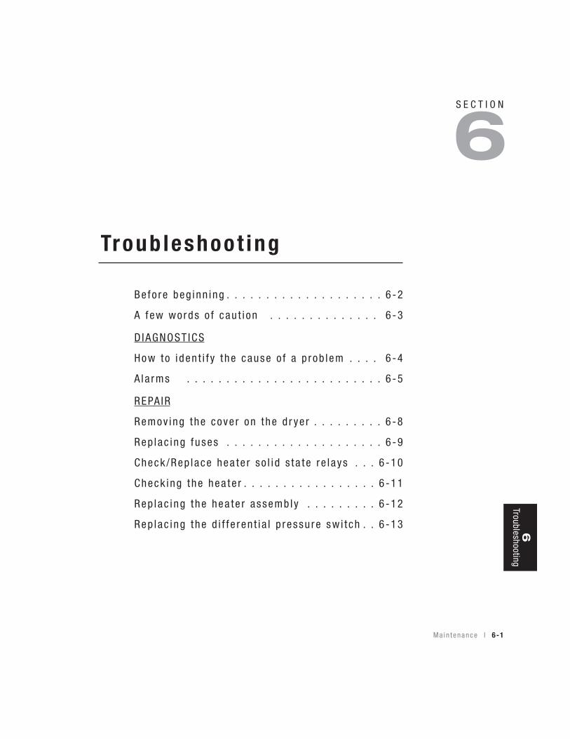
6-1 Troub leshoo t i ngBefore beginning. . . . . . . . . . . . . . . . . . . . . . . . . . . . . . . . . . . . . . . 6-2
A few words of caution . . . . . . . . . . . . . . . . . . . . . . . . . . . . . . . . . 6-3
DIAGNOSTICS
How to identify the cause of a problem . . . . . . . . . . . . . . . . . . . . . 6-4
Alarms . . . . . . . . . . . . . . . . . . . . . . . . . . . . . . . . . . . . . . . . . . . . . 6-5
REPAIR
Removing the cover on the dryer . . . . . . . . . . . . . . . . . . . . . . . . . . 6-8
Replacing fuses. . . . . . . . . . . . . . . . . . . . . . . . . . . . . . . . . . . . . . . . 6-9
i i l Tab l e o f Con ten t s
Check/Replace heater solid state relays . . . . . . . . . . . . . . . . . . . . 6-10
Checking the heater . . . . . . . . . . . . . . . . . . . . . . . . . . . . . . . . . . . 6-11
Replacing the heater assembly . . . . . . . . . . . . . . . . . . . . . . . . . . . 6-12
Replacing the differential pressure switch. . . . . . . . . . . . . . . . . . . 6-13
A A ppend i xWe’re here to help . . . . . . . . . . . . . . . . . . . . . . . . . . . . . . . . . . . . . A-1
How to contact customer service . . . . . . . . . . . . . . . . . . . . . . . . . . A-1
Before you call... . . . . . . . . . . . . . . . . . . . . . . . . . . . . . . . . . . . . . . A-1
Equipment guarantee . . . . . . . . . . . . . . . . . . . . . . . . . . . . . . . . . . A-2
Performance warranty . . . . . . . . . . . . . . . . . . . . . . . . . . . . . . . . . . A-2
Warranty limitations . . . . . . . . . . . . . . . . . . . . . . . . . . . . . . . . . . . . A-2
B A ppend i xDetermining airflow in the SlimLine dryer . . . . . . . . . . . . . . . . . . . . B-1
Relating the heater inlet pressure to the airflow . . . . . . . . . . . . . . . B-1
Calculating the airflow through the hopper to specify the mass
of air . . . . . . . . . . . . . . . . . . . . . . . . . . . . . . . . . . . . . . . . . . B-2
C A ppend i xRTD temperature resistance chart. . . . . . . . . . . . . . . . . . . . . . . . . . C-1
D A ppend i xCompressed air membrane option . . . . . . . . . . . . . . . . . . . . . . . . . D-1
Preparing to install the membrane . . . . . . . . . . . . . . . . . . . . . . . . . D-2
Using the wall mount bracket to mount the membrane assembly . . D-2
Mounting the differential pressure gauge to the filterhead . . . . . . . D-3
Tab le o f Con ten t s l i i i

D A ppend i xInstalling the compressed air piping for membrane
assembly installation . . . . . . . . . . . . . . . . . . . . . . . . . . . . . . D-3
Membrane installation . . . . . . . . . . . . . . . . . . . . . . . . . . . . . . . . . . D-4
Start-up and operation . . . . . . . . . . . . . . . . . . . . . . . . . . . . . . . . . . D-7
Maintenance and troubleshooting (general). . . . . . . . . . . . . . . . . . . D-8
Maintenance and troubleshooting checkpoints . . . . . . . . . . . . . . . . D-9
Filter elements . . . . . . . . . . . . . . . . . . . . . . . . . . . . . . . . . . . . . . . D-10
When to replace a filter element . . . . . . . . . . . . . . . . . . . . . . . . . . D-10
Filter element replacement . . . . . . . . . . . . . . . . . . . . . . . . . . . . . . D-10
Automatic draining mechanism. . . . . . . . . . . . . . . . . . . . . . . . . . . D-13
Drain provisions . . . . . . . . . . . . . . . . . . . . . . . . . . . . . . . . . . . . . . D-14
i v l Tab l e o f Con ten t s
I n t roduc t ion
Purpose o f t he use r gu ide . . . . . . . . . . . . . . 1 -2
Ho w the gu ide i s o rgan i zed . . . . . . . . . . . . . 1 -2
You r r espons ib i l i t i e s as a use r . . . . . . . . . . . 1 -3
ATTENT ION :Read t h i s so no one ge t s hu r t . . . . . . . . 1 -4
S E C T I O N
1
I n t r oduc t i on l 1-1
1In
trodu
ction
✐
Purpose o f the User Gu ideThis User Guide describes the Conair SlimLine Compressed Air Dryerand explains step-by-step how to install, operate, maintain, and repair thisequipment.
Before installing this product, please take a few moments to read the UserGuide and review the diagrams and safety information in the instructionpacket. You also should review manuals covering associated equipment inyour system. This review won’t take long, and it could save you valuableinstallation and operating time later.
How the Gu ide i s O rgan izedSymbols have been used to help organize the User Guide and call yourattention to important information regarding safe installation and operation.
Symbols within triangles warn of conditions that could be hazardous to users orcould damage equipment. Read and take precautions before proceeding.
Numbers indicate tasks or steps to be performed by the user.
A diamond indicates the equipment’s response to an action performed by the user.
An open box marks items in a checklist.
A circle marks items in a list.
Indicates a tip. A tip is used to provide you with a suggestion that will help you withthe maintenance and the operation of this equipment.
Indicates a note. A note is used to provide additional information about the stepsyou are following throughout the manual.
1
◆
❒
•✒
1-2 l I n t r oduc t i on
I n t r oduc t i on l 1-3
Your Respons ib i l i t y as a UserYou must be familiar with all safety procedures concerning installation, opera-tion and maintenance of this equipment. Responsible safety procedures include:
• Thorough review of this User Guide, paying particular attention to hazard warnings, appendices and related diagrams.
• Thorough review of the equipment itself, with careful attention to voltage sources, intended use and warning labels.
• Thorough review of instruction manuals for associated equipment.• Step-by-step adherence to instructions outlined in this User Guide.
1In
trodu
ction

ATTENT ION :Read th is so no one ge ts hur tWe design equipment with the user’s safety in mind. You can avoid the potentialhazards identified on this machine by following the procedures outlined below andelsewhere in the User Guide.
WARNING: Improper ins ta l l a t ion , opera t ion , o rser v ic ing may resu l t i n equ ipment damage o rpersona l in ju r y.
This equipment should be installed, adjusted, and serviced by qualifiedtechnical personnel who are familiar with the construction, operation,and potential hazards of this type of machine.
All wiring, disconnects, and fuses should be installed by qualified elec-trical technicians in accordance with electrical codes in your region.Always maintain a safe ground. Do not operate the equipment at powerlevels other than what is specified on the machine serial tag and dataplate.
WARNING: Vo l tage hazard
This equipment is powered by single-phase alternating current,as specified on the machine serial tag and data plate.
A properly sized conductive ground wire from the incoming power supply must be connected to the chassis ground terminal inside theelectrical enclosure. Improper grounding can result in severe personalinjury and erratic machine operation. (120 Volt units come with agrounded plug. Must be plugged into a grounded out.)
Always disconnect and lock out the incoming main power source beforeopening the electrical enclosure or performing non-standard operatingprocedures, such as routine maintenance. Only qualified personnelshould perform troubleshooting procedures that require access to theelectrical enclosure while power is on.
1-4 l I n t r oduc t i on

1In
trodu
ction
I n t r oduc t i on l 1-5
CAUT ION : Hot Sur facesAlways protect yourself from certain exterior surfaces that canreach temperatures in excess of 200°F {93°C}. These surfacesinclude the hopper cone and the exterior of the dryer casting.Also exercise caution around hot surfaces inside the dryer when cleaning or accessing the inside of the hopper.

1-6 l I n t r oduc t i on

Desc r i p t i on l 2-1
Descr ip t ion
Wha t i s t he S l imL ine -
Compressed a i r d r ye r? . . . . . . . . . . . . . 2 -2
Typ i ca l a pp l i ca t i ons . . . . . . . . . . . . . . . . . . 2 -2
Ho w i t wo rks : S l imL ine . . . . . . . . . . . . . . . . 2 -3
Ho w i t wo rks : Typ i ca l p l an t compressed a i r
s ys tem . . . . . . . . . . . . . . . . . . . . . 2 -4
Spec i f i ca t i ons : S l imL ine . . . . . . . . . . . . . . . 2 -5
S E C T I O N
2
2D
escription
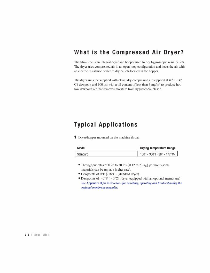
What i s the Compressed A i r D r yer?The SlimLine is an integral dryer and hopper used to dry hygroscopic resin pellets.The dryer uses compressed air in an open loop configuration and heats the air withan electric resistance heater to dry pellets located in the hopper.
The dryer must be supplied with clean, dry compressed air supplied at 40° F {4°C} dewpoint and 100 psi with a oil content of less than 3 mg/m3 to produce hot,low dewpoint air that removes moisture from hygroscopic plastic.
Typ ica l App l i ca t ions
1 Dryer/hopper mounted on the machine throat.
Model Drying Temperature Range
Standard 100° - 350°F {38° - 177°C}
• Throughput rates of 0.25 to 50 lbs {0.12 to 23 kg} per hour (somematerials can be run at a higher rate).
• Dewpoints of 0°F {-18°C} (standard dryer)• Dewpoints of -40°F {-40°C} (dryer equipped with an optional membrane)
See Appendix D for instructions for installing, operating and troubleshooting the
optional membrane assembly.
2-2 l Desc r i p t i on
Material InAir Out
Material Out
Membrane
FilterFilter
Pressure Gauge
Optional Membrane
From Plant Distribution System
Isolation Valve
Desc r i p t i on l 2-3
2D
escription
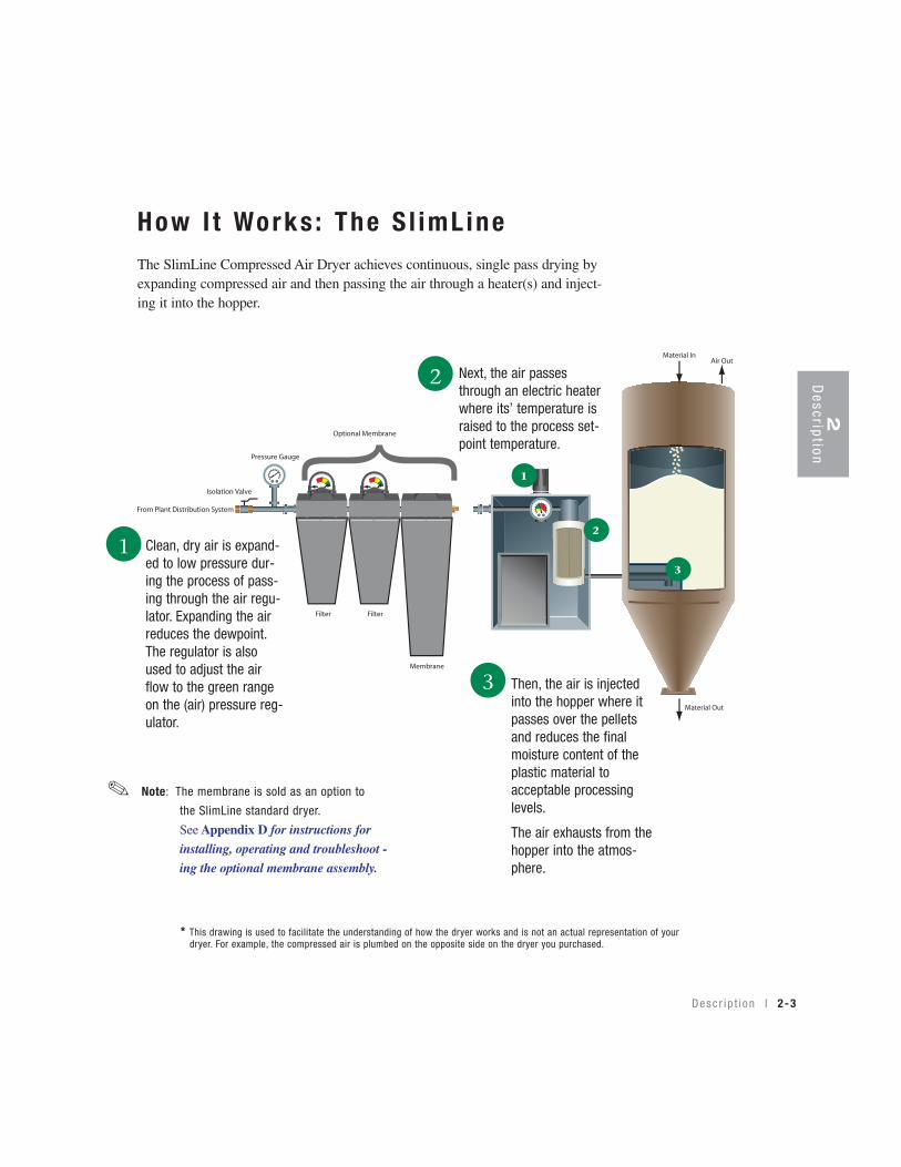
How I t Works : The S l imL ineThe SlimLine Compressed Air Dryer achieves continuous, single pass drying byexpanding compressed air and then passing the air through a heater(s) and inject-ing it into the hopper.
Clean, dry air is expand-ed to low pressure dur-ing the process of pass-ing through the air regu-lator. Expanding the airreduces the dewpoint.The regulator is alsoused to adjust the airflow to the green rangeon the (air) pressure reg-ulator.
Next, the air passesthrough an electric heaterwhere its’ temperature israised to the process set-point temperature.
Then, the air is injectedinto the hopper where itpasses over the pelletsand reduces the finalmoisture content of theplastic material toacceptable processinglevels.
The air exhausts from thehopper into the atmos-phere.
1
2
3
1
2
3
Note: The membrane is sold as an option to
the SlimLine standard dryer.
See Appendix D for instructions for
installing, operating and troubleshoot -
ing the optional membrane assembly.
{✐
* This drawing is used to facilitate the understanding of how the dryer works and is not an actual representation of yourdryer. For example, the compressed air is plumbed on the opposite side on the dryer you purchased.
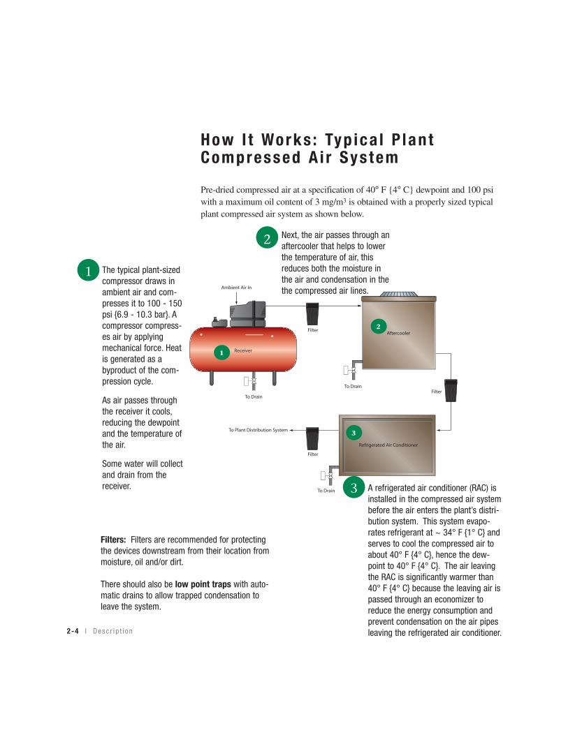
How I t Works : Typ ica l P lan tCompressed A i r Sys tem
Pre-dried compressed air at a specification of 40° F {4° C} dewpoint and 100 psiwith a maximum oil content of 3 mg/m3 is obtained with a properly sized typicalplant compressed air system as shown below.
2-4 l Desc r i p t i on
Ambient Air In
Receiver
Aftercooler
Refrigerated Air Conditioner
To Drain
To Drain
Filter
Filter
Filter
To Plant Distribution System
To Drain
The typical plant-sizedcompressor draws inambient air and com-presses it to 100 - 150psi {6.9 - 10.3 bar}. Acompressor compress-es air by applyingmechanical force. Heatis generated as abyproduct of the com-pression cycle.
As air passes throughthe receiver it cools,reducing the dewpointand the temperature ofthe air.
Some water will collectand drain from thereceiver.
Next, the air passes through anaftercooler that helps to lowerthe temperature of air, thisreduces both the moisture inthe air and condensation in thethe compressed air lines.
A refrigerated air conditioner (RAC) isinstalled in the compressed air systembefore the air enters the plant’s distri-bution system. This system evapo-rates refrigerant at ~ 34° F {1° C} andserves to cool the compressed air toabout 40° F {4° C}, hence the dew-point to 40° F {4° C}. The air leavingthe RAC is significantly warmer than40° F {4° C} because the leaving air ispassed through an economizer toreduce the energy consumption andprevent condensation on the air pipesleaving the refrigerated air conditioner.
1
2
3
1
2
3
Filters: Filters are recommended for protectingthe devices downstream from their location frommoisture, oil and/or dirt.
There should also be low point traps with auto-matic drains to allow trapped condensation toleave the system.

2D
escription
D esc r i p t i on l 2-5
Spec i f i ca t ions : S l imL ineCompressed A i r D r yers
B C
A
MODEL SL2.5 SL5 SL15 SL25 SL50Performance characteristics (with full hopper)
Drying temperature All models 100 - 350°F {38 - 176°C}Dewpoint 0°F {-18°C} with optional membrane - 40°F {- 40°C}Airflow SCFM {SLM} 2.5 {70.8} 5 {141.6} 7.5 {212.4} 12.5 {354.0} 25.0 {708.0}Airflow with membrane SCFM {SLM} 3.1 {88.0} 6.8 {193.0} 9.3 {263.0} 15.7 {445.0} 34.9 {988.3}Hopper volume ft3 {L} 0.125 {3.5} 0.25 {7.1} 0.75 {21.2} 1.25 {35.4} 2.5 {71.0}Heater size kW 1 1 1 2 2
Dimensions inches {cm}A - Height 22.5 {57.2} 40.0 {101.6} 26.5 {67.3} 32.0 {81.3} 47.5 {120.7}B - Overall width 11.0 {27.9} 11.0 {27.9} 12.5 {31.8} 15.5 {39.4} 15.5 {39.4}C- Depth 19.0 {48.3} 19.0 {48.3} 25.5 {64.8} 24.0 {61.0} 24.0 {61.0}Drying hopper inlet pipe size 1/2 NPT female
Weight lbs {kg}Standard dryer installed (empty) 32 {14.5} 37 {17} 56 {25) 87 {39} 107 {49}Shipping 60 {27.2} 70 {31.8} 160 {72.6} 160 {72.6} 160 {72.6}
Voltage - Total amps120 V/1phase/60 Hz 8.5 8.5 8.5 16.7 16.7220 V/1 phase/50 Hz 4.3 4.3 4.3 8.4 8.4
Compressed air requirements 100 PSI, clean dry compressed air pressure
dewpoint of 40°F {5°C} ; residual oil content of less than 3 mg/m3
SPECIFICATIONNOTES:SCFM - Standard CubicFeet per Minute
SLM - Standard Liters per Minute
*Compressed air suppliedto the dryer must meetspecification requirementof 100 psi and 40°F {4°C}dewpoint and a residualoil content of less than3mg/m3 .
Specifications may change
without notice. Consult a
Conair representative for
the most current informa-
tion.
APPLICATION NOTES:
Conair recommends purchasing the optional membrane when:● your process requires that you obtain a dewpoint of -40°F {- 40°C}; or the compressed air dewpoint you are sup-
pling is above 40°F {4°C}.
B
A
C
Front ViewModels SL2.5
and SL5
Front ViewModel SL15, 25 and 50
Side ViewModel SL15, 25 and 50
{This portion ofthe hopper onlyon ModelSL50 {
Side ViewModels SL2.5
and SL5
This portion ofthe hopper onlyon ModelSL50
compressed air inlet
compressed air inlet
TPDS026/0506
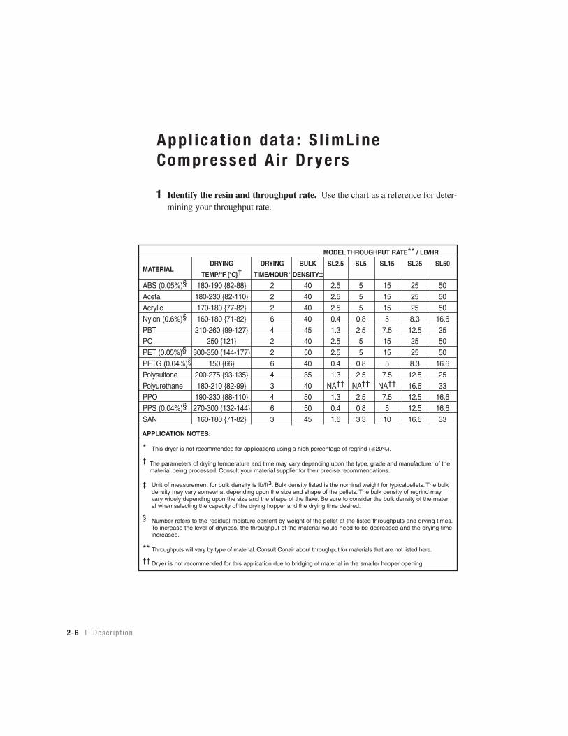
MODEL THROUGHPUT RATE** / LB/HR
DRYING DRYING BULK SL2.5 SL5 SL15 SL25 SL50MATERIAL
TEMP/°F {°C}† TIME/HOUR* DENSITY‡
ABS (0.05%)§ 180-190 {82-88} 2 40 2.5 5 15 25 50Acetal 180-230 {82-110} 2 40 2.5 5 15 25 50Acrylic 170-180 {77-82} 2 40 2.5 5 15 25 50Nylon (0.6%)§ 160-180 {71-82} 6 40 0.4 0.8 5 8.3 16.6PBT 210-260 {99-127} 4 45 1.3 2.5 7.5 12.5 25PC 250 {121} 2 40 2.5 5 15 25 50PET (0.05%)§ 300-350 {144-177} 2 50 2.5 5 15 25 50PETG (0.04%)§ 150 {66} 6 40 0.4 0.8 5 8.3 16.6Polysulfone 200-275 {93-135} 4 35 1.3 2.5 7.5 12.5 25Polyurethane 180-210 {82-99} 3 40 NA†† NA†† NA†† 16.6 33PPO 190-230 {88-110} 4 50 1.3 2.5 7.5 12.5 16.6PPS (0.04%)§ 270-300 {132-144} 6 50 0.4 0.8 5 12.5 16.6SAN 160-180 {71-82} 3 45 1.6 3.3 10 16.6 33
APPLICATION NOTES:
* This dryer is not recommended for applications using a high percentage of regrind ( 20%).
† The parameters of drying temperature and time may vary depending upon the type, grade and manufacturer of thematerial being processed. Consult your material supplier for their precise recommendations.
‡ Unit of measurement for bulk density is lb/ft3. Bulk density listed is the nominal weight for typicalpellets. The bulk density may vary somewhat depending upon the size and shape of the pellets. The bulk density of regrind may vary widely depending upon the size and the shape of the flake. Be sure to consider the bulk density of the material when selecting the capacity of the drying hopper and the drying time desired.
§ Number refers to the residual moisture content by weight of the pellet at the listed throughputs and drying times.To increase the level of dryness, the throughput of the material would need to be decreased and the drying time increased.
** Throughputs will vary by type of material. Consult Conair about throughput for materials that are not listed here.
†† Dryer is not recommended for this application due to bridging of material in the smaller hopper opening.
2-6 l Desc r i p t i on
App l ica t ion da ta : S l imL ineCompressed A i r D r yers
1 Identify the resin and throughput rate. Use the chart as a reference for deter-mining your throughput rate.
I n s t a l l a t i on l 3-1
I ns ta l l a t ion
Unpack ing t he boxes . . . . . . . . . . . . . . . . . 3 -2
P repa r i ng f o r i n s t a l l a t i on . . . . . . . . . . . . . . 3 -3
L i f t i ng t he d r ye r (mode l s SL 25 and 50 ) . . . . 3 -4
Moun t i ng t he hoppe r /d r ye r un i t . . . . . . . . . . 3 -5
Moun t i ng a l oade r on to t he hoppe r . . . . . . . . 3 -6
Moun t i ng a hand- f i l l l i d ( op t i ona l ) on mode l s
SL15 , SL25 and SL50 . . . . . . . . . . . . . . 3 -7
Connec t i ng t he ma in po wer . . . . . . . . . . . . . 3 -7
Connec t i ng a compressed a i r supp l y . . . . . . . 3 -8
S E C T I O N
3
3In
stallation
3-2 l I n s t a l l a t i on
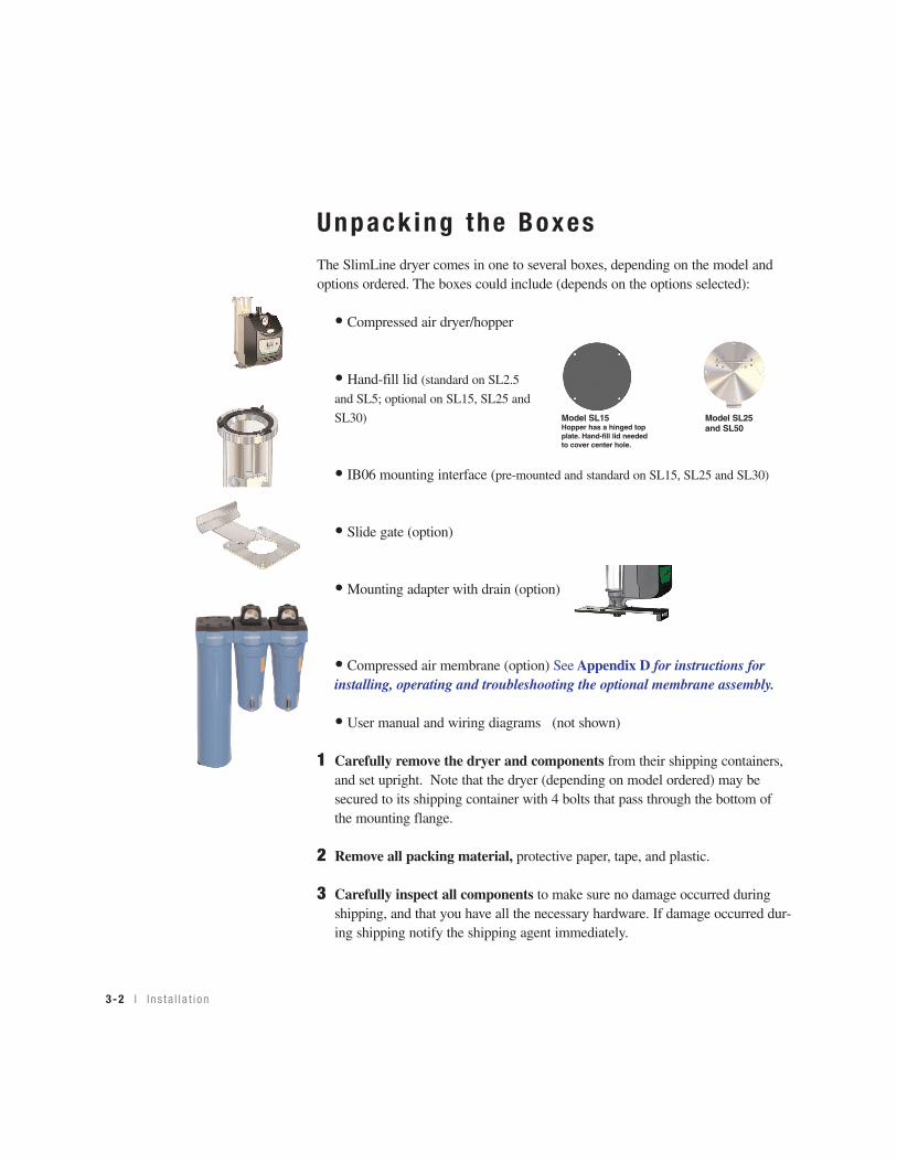
Unpack ing the BoxesThe SlimLine dryer comes in one to several boxes, depending on the model andoptions ordered. The boxes could include (depends on the options selected):
• Compressed air dryer/hopper
• Hand-fill lid (standard on SL2.5
and SL5; optional on SL15, SL25 and
SL30)
• IB06 mounting interface (pre-mounted and standard on SL15, SL25 and SL30)
• Slide gate (option)
• Mounting adapter with drain (option)
• Compressed air membrane (option) See Appendix D for instructions forinstalling, operating and troubleshooting the optional membrane assembly.
• User manual and wiring diagrams (not shown)
1 Carefully remove the dryer and components from their shipping containers,and set upright. Note that the dryer (depending on model ordered) may besecured to its shipping container with 4 bolts that pass through the bottom ofthe mounting flange.
2 Remove all packing material, protective paper, tape, and plastic.
3 Carefully inspect all components to make sure no damage occurred duringshipping, and that you have all the necessary hardware. If damage occurred dur-ing shipping notify the shipping agent immediately.
Model SL25and SL50
Model SL15Hopper has a hinged topplate. Hand-fill lid neededto cover center hole.

I n s t a l l a t i on l 3-3
3In
stallation
Prepar ing fo r Ins ta l l a t ionThe SlimLine dryer is easy to install if you plan the location and prepare themounting area properly.
1 Make sure the mounting area provides:
❒❒ A grounded power source supplying the voltage and correct currentfor your dryer model. Check the dryer’s serial tag (models 2.5 and 5, locatedon the right side of the cover; models 15, 25 and 50 on the back of the hop-per) for the correct amps, voltage, phase, and cycles. Any field wiring shouldbe completed by qualified personnel to the planned location for the dryer. Allelectrical wiring should comply with your region’s electrical codes.
❒❒ Clearance for safe operation and maintenance.
❒❒ A compressed air supply. It is necessary to supply compressed air tothe dryer. Your plant system must be capable of supplying 100 psi {6.9bar}and 40°F {4°C} dewpoint with a residual oil content of less than 3mg/m3.
IMPORTANT: The flow rate of the compressed air must be at 100 psi {6.9 bar} at the
entrance to the dryer (or the optional membrane). If your plant compressed air system,
does not meet this specification you will not achieve desired drying results.
Note: If your compressed air system is not capable of supplying the Conair
recommended dewpoint listed above you will need to purchase the optional mem-
brane to ensure proper drying.
❒❒ Flex hose for connecting compressed air to the dryer. It is also accept-able to use a rigid, 1/2 inch NPT union and compressed air supply pipe tomake the connection from the compressed air source to the dryer.See Installation section entitled, Connecting a compressed air supply.
❒❒ Conair recommends the installation of an isolation valve installed onthe compressed air line leading to the dryer or membrane (if installed).You will use the valve to shut off compressed air to your dryer for cleanout,material changes or maintenance.
❒❒ Conair recommends the installation of a pressure gauge (0 - 160 psi){0 - 11 bar} downstream of the isolation valve to check the supply of airpressure being supplied to the dryer. You will need to install the pressuregauge before the membrane (if installed) or the dryer to obtain accurate pres-sure readings.
✐
See Appendix D forinstructions forinstalling, operatingand troubleshootingthe optional mem-brane assembly.
3-4 l I n s t a l l a t i on
L i f t ing the Dr yers (Mode ls SL25 and SL50)
For increased safety in lifting Conair recommends that all dryer/hopper units arelifted without material in the hopper. When using the lifting lugs on models SL25and SL50 it is required that no material be in the hopper.
1 Bolt the upper section of the hopper (model SL50 securely into place.) Thisprevents the twist lock feature from unlocking and separating. See illustrationsbelow.
2 Bolt the loader adapter plate (models SL25 and SL50) securely in place.This secures the lid to the hopper and prevents it from sliding off during instal-lation. See illustration below.
3 Use the lifting lugs (models SL25 and 50) to lift the empty dryer onto themounting location.
4 Remove the lifting lugs (SL25 and 50) after mounting the dryer.
5 Reverse the procedure to remove the dryer from the machine.
The screw behind thedoor (near the top of thehinge) must be tightenedto secure upper sectionof the hopper.(SL50)
The screw on top of theloader adapter plate must betightened to secure the lid tothe hopper. (SL25 and SL50)
Front ViewModel SL50
Front ViewModel SL25
Lifting lugs
Top ViewModel SL25
Lifting lugs
CAUTION: Always makesure that the top section ofthe SL50 is securelyattached before lifting theunit. Always make sure theloader adapter plate issecure on the SL25 andSL50 before lifting the units.Failure to do so could resultin injury to personnel.
I n s t a l l a t i on l 3-5
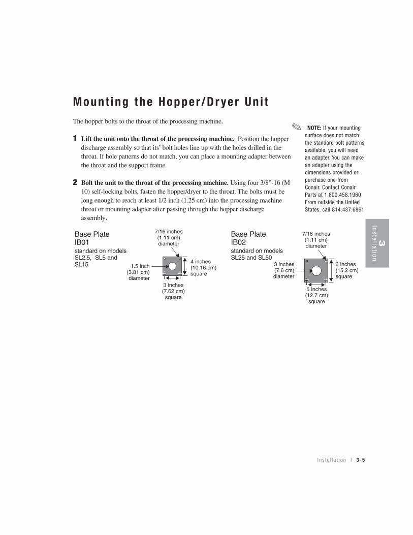
Mount ing the Hopper /Dr yer Un i t The hopper bolts to the throat of the processing machine.
1 Lift the unit onto the throat of the processing machine. Position the hopperdischarge assembly so that its’ bolt holes line up with the holes drilled in thethroat. If hole patterns do not match, you can place a mounting adapter betweenthe throat and the support frame.
2 Bolt the unit to the throat of the processing machine. Using four 3/8”-16 (M10) self-locking bolts, fasten the hopper/dryer to the throat. The bolts must belong enough to reach at least 1/2 inch (1.25 cm) into the processing machinethroat or mounting adapter after passing through the hopper dischargeassembly.
7/16 inches(1.11 cm)diameter
4 inches(10.16 cm)square
1.5 inch(3.81 cm)diameter
3 inches(7.62 cm)
square
6 inches(15.2 cm)square
7/16 inches(1.11 cm)diameter
5 inches(12.7 cm)
square
3 inches(7.6 cm)diameter
Base Plate IB02standard on models SL25 and SL50
Base PlateIB01standard on models SL2.5, SL5 andSL15 ▲
▲
▲▲
▲
▲
▲
▲▲
▲
▲
▲
NOTE: If your mountingsurface does not matchthe standard bolt patternsavailable, you will needan adapter. You can makean adapter using thedimensions provided orpurchase one fromConair. Contact ConairParts at 1.800.458.1960From outside the UnitedStates, call 814.437.6861
✐
3In
stallation
3-6 l I n s t a l l a t i on
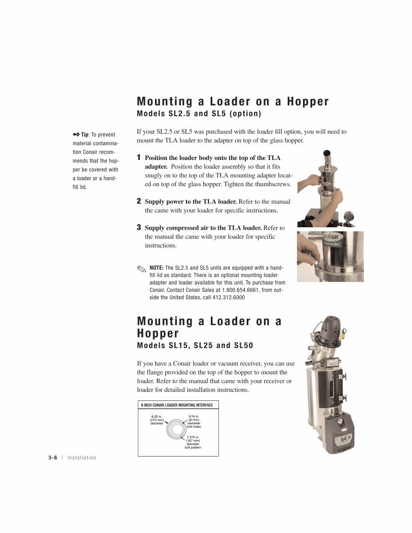
Mount ing a Loader on a HopperMode ls SL2 .5 and SL5 (op t ion )
If your SL2.5 or SL5 was purchased with the loader fill option, you will need tomount the TLA loader to the adapter on top of the glass hopper.
1 Position the loader body onto the top of the TLAadapter. Position the loader assembly so that it fitssnugly on to the top of the TLA mounting adapter locat-ed on top of the glass hopper. Tighten the thumbscrews.
2 Supply power to the TLA loader. Refer to the manualthe came with your loader for specific instructions.
3 Supply compressed air to the TLA loader. Refer tothe manual the came with your loader for specificinstructions.
Mount ing a Loader on aHopperMode ls SL15 , SL25 and SL50
If you have a Conair loader or vacuum receiver, you can usethe flange provided on the top of the hopper to mount theloader. Refer to the manual that came with your receiver orloader for detailed installation instructions.
8-INCH CONAIR LOADER MOUNTING INTERFACE
8.25 in.(210 mm)diameter
7.375 in.(187 mm)diameter
bolt pattern
5/16 in.(8 mm)
diameter bolt holes
NOTE: The SL2.5 and SL5 units are equipped with a hand-fill lid as standard. There is an optional mounting loaderadapter and loader available for this unit. To purchase fromConair. Contact Conair Sales at 1.800.654.6661, from out-side the United States, call 412.312.6000
✐
✒Tip: To prevent
material contamina-
tion Conair recom-
mends that the hop-
per be covered with
a loader or a hand-
fill lid.
I n s t a l l a t i on l 3-7
Connec t ing the Ma in Power
The dryer operates from standard 120 Volt, 60 Hz or 220 Volt, 50 Hz depending onthe option selected when purchased.
1 Plug the dryer into a properly sized electrical outlet.
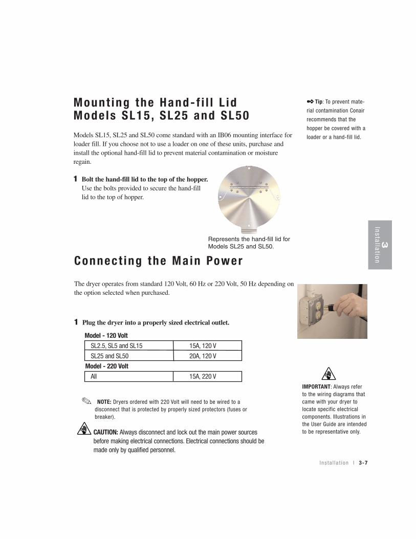
Mount ing the Hand- f i l l L id Mode ls SL15 , SL25 and SL50Models SL15, SL25 and SL50 come standard with an IB06 mounting interface forloader fill. If you choose not to use a loader on one of these units, purchase andinstall the optional hand-fill lid to prevent material contamination or moistureregain.
1 Bolt the hand-fill lid to the top of the hopper.Use the bolts provided to secure the hand-filllid to the top of hopper.
SL2.5, SL5 and SL15 15A, 120 V
SL25 and SL50 20A, 120 V
Model - 120 Volt
All 15A, 220 V
Model - 220 Volt
NOTE: Dryers ordered with 220 Volt will need to be wired to adisconnect that is protected by properly sized protectors (fuses orbreaker).
✐
Represents the hand-fill lid forModels SL25 and SL50.
✒Tip: To prevent mate-
rial contamination Conair
recommends that the
hopper be covered with a
loader or a hand-fill lid.
3In
stallation
IMPORTANT: Always referto the wiring diagrams thatcame with your dryer tolocate specific electricalcomponents. Illustrations inthe User Guide are intendedto be representative only.CAUTION: Always disconnect and lock out the main power sources
before making electrical connections. Electrical connections should bemade only by qualified personnel.
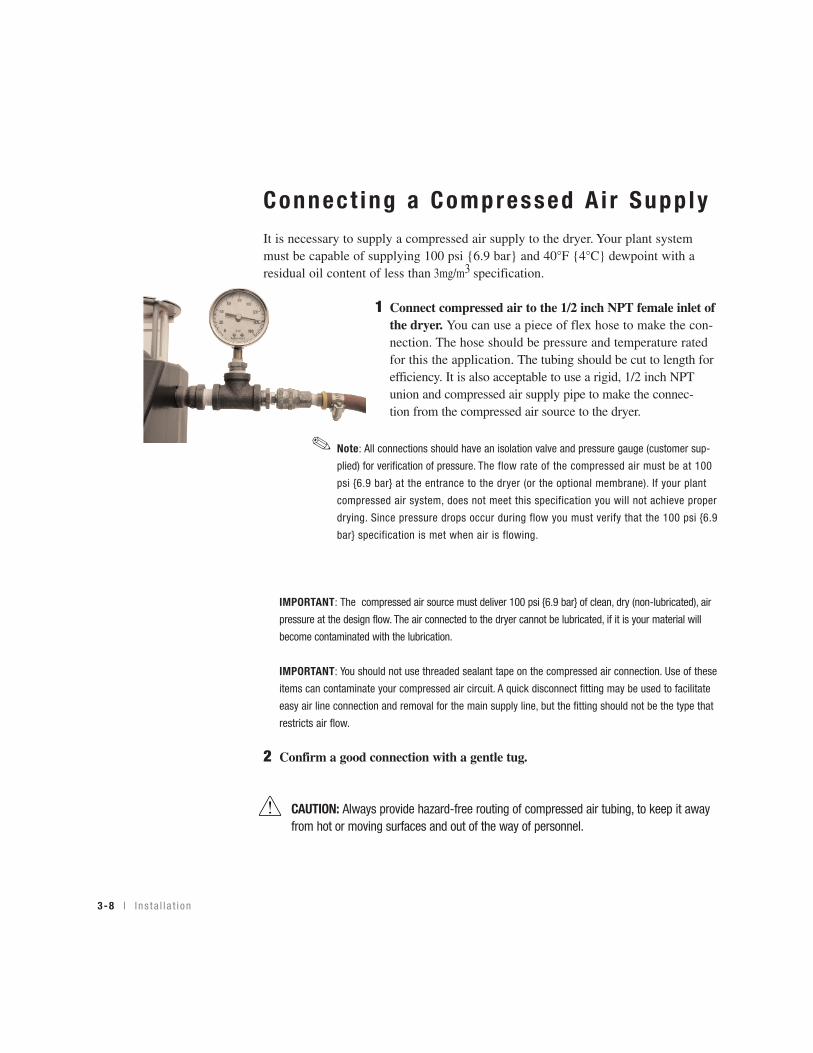
Connect ing a Compressed A i r Supp lyIt is necessary to supply a compressed air supply to the dryer. Your plant systemmust be capable of supplying 100 psi {6.9 bar} and 40°F {4°C} dewpoint with aresidual oil content of less than 3mg/m3 specification.
1 Connect compressed air to the 1/2 inch NPT female inlet ofthe dryer. You can use a piece of flex hose to make the con-nection. The hose should be pressure and temperature rated for this the application. The tubing should be cut to length for efficiency. It is also acceptable to use a rigid, 1/2 inch NPT union and compressed air supply pipe to make the connec-tion from the compressed air source to the dryer.
IMPORTANT: The compressed air source must deliver 100 psi {6.9 bar} of clean, dry (non-lubricated), air
pressure at the design flow. The air connected to the dryer cannot be lubricated, if it is your material will
become contaminated with the lubrication.
IMPORTANT: You should not use threaded sealant tape on the compressed air connection. Use of these
items can contaminate your compressed air circuit. A quick disconnect fitting may be used to facilitate
easy air line connection and removal for the main supply line, but the fitting should not be the type that
restricts air flow.
2 Confirm a good connection with a gentle tug.
CAUTION: Always provide hazard-free routing of compressed air tubing, to keep it awayfrom hot or moving surfaces and out of the way of personnel.
✐Note: All connections should have an isolation valve and pressure gauge (customer sup-
plied) for verification of pressure. The flow rate of the compressed air must be at 100
psi {6.9 bar} at the entrance to the dryer (or the optional membrane). If your plant
compressed air system, does not meet this specification you will not achieve proper
drying. Since pressure drops occur during flow you must verify that the 100 psi {6.9
bar} specification is met when air is flowing.
3-8 l I n s t a l l a t i on

S E C T I O N
4
4O
peration
Opera t ion
The S l imL ine : con t r o l pane l . . . . . . . . . . . . . 4 -2
Load ing ma te r i a l i n t o t he hoppe r . . . . . . . . . 4 -3
Ad jus t i ng t he p ressu re r egu l a t o r . . . . . . . . . 4 -3
To s t a r t d r y i ng . . . . . . . . . . . . . . . . . . . . . 4 -4
To s t op d r y i ng . . . . . . . . . . . . . . . . . . . . . 4 -5
Se t t i ng t he h i gh a l a rm se tpo in t . . . . . . . . . . 4 -6
Chang ing t he t empera tu re un i t s
( f ah renhe i t / ce l s i us ) . . . . . . . . . . . . . . . . . . 4 -6
Ins ta l l i ng t he op t i ona l s l i de ga te . . . . . . . . . 4 -7
Ins ta l l i ng t he op t i ona l d ra i n va l ve . . . . . . . . 4 -8
Us ing t he op t i ona l s l i de ga te . . . . . . . . . . . . 4 -9
Us ing t he op t i ona l d ra i n va l ve . . . . . . . . . . 4 -10
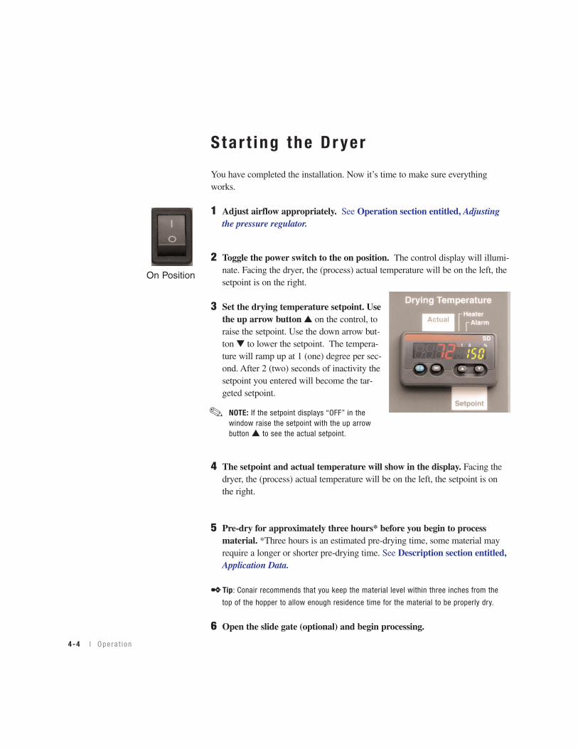
Opera t i on l 4-1

Drying Temperature
ActualHeater
Alarm
Setpoint
Control Codes:- High Temp. Alarm- Input Error- Heater Off- Ramping Target- Heater Output (%)
A2.hiER.in
OFFrP.tGPo.ht
Startup:1. With dryer power off, start airflow.2. Adjust airflow to green zone.3. Switch on dryer.
Shutdown:1. Lower setpoint to OFF.2. Switch off dryer.3. Allow to cool 1 minute.4. Stop airflow.
1 2 %
SD
The SL Ser ies Compressed A i r D r yer Cont ro l
Cont ro l Codes
See Section 6,Troubleshootingfor a list of possi-ble causes andsolutions for theAlarms.
Heate r S ta tusIndicates the heaterstatus.
Actua l Dr y ing Tempera tureShows the (process) actual temperaturevalue.
ON/OFF Togg leSwi tch
Used to turn thepower on or off.
Note: The heaterpower circuit is stillenergized when theswitch is off.
AlarmInd ica t ion Indicates thealarm status.(HighTemperatureAlarm only.)
Setpo in t Dr y ingTempera tureShows the setpointtemperature value.
4-2 l Ope ra t i on
Return But ton (g reen )Cycles through:
Po.ht - heater percentage (%) on time (read only -can help with troubleshooting)
A2.hi - high temperature alarm setpoint (adjustablewith arrow keys)
Celsius - Fahrenheit - Changes from °F to °C (changewith arrow keys)
Er.in - input error
OFF - displays when the heater has been disabled.
rP.tG- displays when a new setpoint has been selected (temporary target temperature)
Note: See Section 6, Troubleshooting, for additionalinformation.

4O
peration
O pe ra t i on l 4-3
Load ing Mater ia l i n to the Hopper
1 Use your installed conveying equipment or hand-fill material into the hop-per.
✒Tip: If you hand-fill your hopper remember to close the lid to reduce moisture regain
and to keep you material contaminant-free.
Adjus t ing the P ressure Regu la to r
1 Turn the knob of the pressure regulator in aclockwise direction to allow increased airflow.
Note: If the regulator does not move easily, pull up on the
knob to unlock it.
2 Adjust the air flow so that the pressure gaugereads at the top of the green level.
3 Push down on the knob to lock the pressuregauge at a flow rate in the green area on thegauge.
CAUTION: DO NOT set the pressure in the red section of the pressure gauge. Damage to
the internal components of the dryer can occur at high pressure.
DO NOT set the pressure in the red
section of the pressure gauge.
✐
Star t ing the Dr yer
You have completed the installation. Now it’s time to make sure everythingworks.
1 Adjust airflow appropriately. See Operation section entitled, Adjustingthe pressure regulator.
2 Toggle the power switch to the on position. The control display will illumi-nate. Facing the dryer, the (process) actual temperature will be on the left, the setpoint is on the right.
3 Set the drying temperature setpoint. Usethe up arrow button ▲ on the control, toraise the setpoint. Use the down arrow but-ton ▼ to lower the setpoint. The tempera-ture will ramp up at 1 (one) degree per sec-ond. After 2 (two) seconds of inactivity thesetpoint you entered will become the tar-geted setpoint.
4 The setpoint and actual temperature will show in the display. Facing thedryer, the (process) actual temperature will be on the left, the setpoint is onthe right.
5 Pre-dry for approximately three hours* before you begin to processmaterial. *Three hours is an estimated pre-drying time, some material mayrequire a longer or shorter pre-drying time. See Description section entitled,Application Data.
✒Tip: Conair recommends that you keep the material level within three inches from the
top of the hopper to allow enough residence time for the material to be properly dry.
6 Open the slide gate (optional) and begin processing.
On Position
NOTE: If the setpoint displays “OFF” in thewindow raise the setpoint with the up arrowbutton ▲ to see the actual setpoint.
✐
4-4 l Ope ra t i on
4O
peration
O pe ra t i on l 4-5
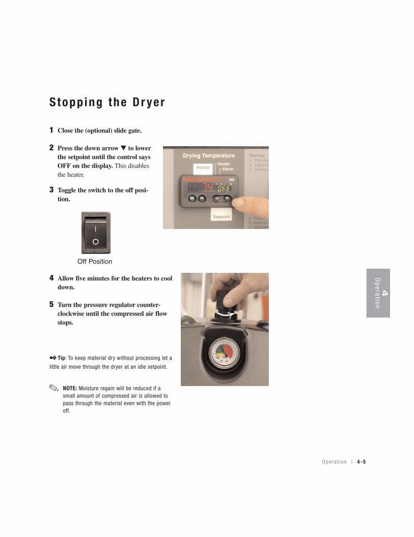
S topp ing the Dr yer
1 Close the (optional) slide gate.
2 Press the down arrow ▼ to lowerthe setpoint until the control saysOFF on the display. This disablesthe heater.
3 Toggle the switch to the off posi-tion.
4 Allow five minutes for the heaters to cooldown.
5 Turn the pressure regulator counter-clockwise until the compressed air flowstops.
✒Tip: To keep material dry without processing let a
little air move through the dryer at an idle setpoint.
Off Position
NOTE: Moisture regain will be reduced if asmall amount of compressed air is allowed topass through the material even with the poweroff.
✐
4-6 l Ope ra t i on
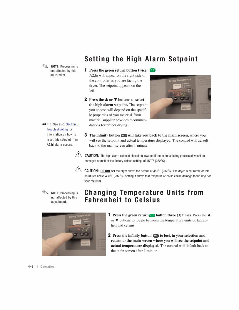
Set t ing the H igh A la rm Se tpo in t1 Press the green return button twice.
A2.hi will appear on the right side of the controller as you are facing the dryer. The setpoint appears on the left.
2 Press the ▲▲ or ▼▼ buttons to selectthe high alarm setpoint. The setpointyou choose will depend on the specif-ic properties of you material. Yourmaterial supplier provides recommen-dations for proper drying.
3 The infinity button will take you back to the main screen, where youwill see the setpoint and actual temperature displayed. The control will defaultback to the main screen after 1 minute.
CAUTION: The high alarm setpoint should be lowered if the material being processed would be
damaged or melt at the factory default setting of 450°F {232°C}.
CAUTION: DO NOT set the dryer above the default of 450°F {232°C}. The dryer is not rated for tem-
peratures above 450°F {232°C}. Setting it above that temperature could cause damage to the dryer or
your material.
Chang ing Tempera ture Un i ts f romFahrenhe i t to Ce ls ius
1 Press the green return button three (3) times. Press the ▲or ▼ buttons to toggle between the temperature units of fahren-heit and celsius.
2 Press the infinity button to lock in your selection and return to the main screen where you will see the setpoint and actual temperature displayed. The control will default back to the main screen after 1 minute.
NOTE: Processing isnot affected by thisadjustment.
✐
NOTE: Processing isnot affected by thisadjustment.
✐
✒Tip: See also, Section 6,
Troubleshooting for
information on how to
reset this setpoint if an
A2.hi alarm occurs.
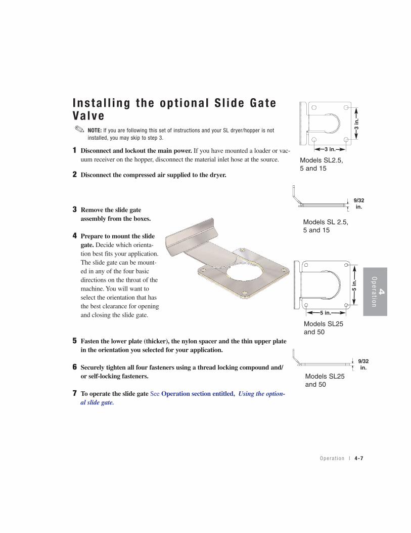
I ns ta l l i ng the op t iona l S l ide Ga teVa lve
1 Disconnect and lockout the main power. If you have mounted a loader or vac-uum receiver on the hopper, disconnect the material inlet hose at the source.
2 Disconnect the compressed air supplied to the dryer.
3 Remove the slide gateassembly from the boxes.
4 Prepare to mount the slidegate. Decide which orienta-tion best fits your application.The slide gate can be mount-ed in any of the four basicdirections on the throat of themachine. You will want toselect the orientation that hasthe best clearance for openingand closing the slide gate.
5 Fasten the lower plate (thicker), the nylon spacer and the thin upper platein the orientation you selected for your application.
6 Securely tighten all four fasteners using a thread locking compound and/or self-locking fasteners.
7 To operate the slide gate See Operation section entitled, Using the option-al slide gate.
Opera t i on l 4-7
Models SL 2.5,5 and 15
3 in.
3 in
.
9/32in.
5 in
.
5 in.
9/32in.
Models SL2.5,5 and 15
Models SL25and 50
Models SL25and 50
4O
peration
NOTE: If you are following this set of instructions and your SL dryer/hopper is notinstalled, you may skip to step 3.
✐
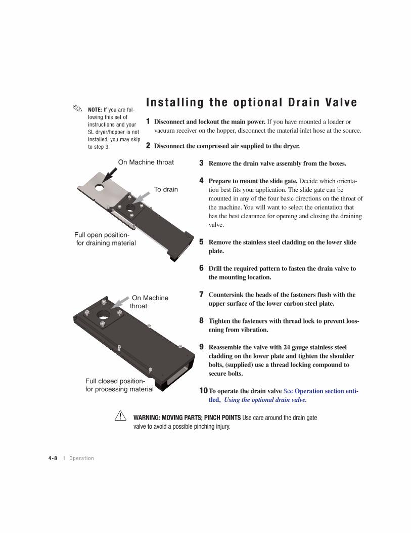
I ns ta l l i ng the op t iona l Dra in Va lve1 Disconnect and lockout the main power. If you have mounted a loader or
vacuum receiver on the hopper, disconnect the material inlet hose at the source.
2 Disconnect the compressed air supplied to the dryer.
3 Remove the drain valve assembly from the boxes.
4 Prepare to mount the slide gate. Decide which orienta-tion best fits your application. The slide gate can be mounted in any of the four basic directions on the throat ofthe machine. You will want to select the orientation that has the best clearance for opening and closing the drainingvalve.
5 Remove the stainless steel cladding on the lower slide plate.
6 Drill the required pattern to fasten the drain valve to the mounting location.
7 Countersink the heads of the fasteners flush with the upper surface of the lower carbon steel plate.
8 Tighten the fasteners with thread lock to prevent loos-ening from vibration.
9 Reassemble the valve with 24 gauge stainless steel cladding on the lower plate and tighten the shoulder bolts, (supplied) use a thread locking compound to secure bolts.
10To operate the drain valve See Operation section enti-tled, Using the optional drain valve.
Full open position-for draining material
Full closed position-for processing material
On Machinethroat
On Machine throat
To drain
4-8 l Ope ra t i on
NOTE: If you are fol-lowing this set ofinstructions and yourSL dryer/hopper is notinstalled, you may skipto step 3.
✐
WARNING: MOVING PARTS; PINCH POINTS Use care around the drain gatevalve to avoid a possible pinching injury.

4O
peration
Us ing the S l ide Ga te Va lve1 Turn off and disconnect the main power supply to the dryer.
2 Pull the handle toward the front of the dryer to open the slide gate.
3 Push the handle toward the rear of the dryer to close the slide gate.
NOTE: In an intermediate position the material will be shut offfrom the throat of the machine and not drained.
✐
WARNING: MOVING PARTS; PINCH POINTS Use care around the slide gatevalve to avoid a possible pinching injury.
Open Position
Handle
To Close
Opera t i on l 4-9
4-10 l Ope ra t i on
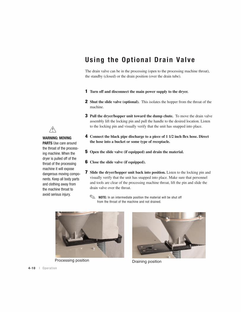
Us ing the Opt iona l Dra in Va lveThe drain valve can be in the processing (open to the processing machine throat),the standby (closed) or the drain position (over the drain tube).
1 Turn off and disconnect the main power supply to the dryer.
2 Shut the slide valve (optional). This isolates the hopper from the throat of themachine.
3 Pull the dryer/hopper unit toward the dump chute. To move the drain valveassembly lift the locking pin and pull the handle to the desired location. Listento the locking pin and visually verify that the unit has snapped into place.
4 Connect the black pipe discharge to a piece of 1 1/2 inch flex hose. Directthe hose into a bucket or some type of receptacle.
5 Open the slide valve (if equipped) and drain the material.
6 Close the slide valve (if equipped).
7 Slide the dryer/hopper unit back into position. Listen to the locking pin andvisually verify that the unit has snapped into place. Make sure that personneland tools are clear of the processing machine throat, lift the pin and slide thedrain valve over the throat.
NOTE: In an intermediate position the material will be shut offfrom the throat of the machine and not drained.
✐
WARNING: MOVINGPARTS Use care aroundthe throat of the process-ing machine. When thedryer is pulled off of thethroat of the processingmachine it will exposedangerous moving compo-nents. Keep all body partsand clothing away fromthe machine throat toavoid serious injury.
Processing position Draining position
Main tenance
Preven ta t i ve ma in tenance check l i s t . . . . . . . 5 -2
C lean ing t he hoppe r . . . . . . . . . . . . . . . . . . 5 -3
Inspec t i ng hoses . . . . . . . . . . . . . . . . . . . 5 -4
S E C T I O N
5M
ainten
ance
5
Main tenance l 5-1
5-2 l Ma in tenance
Preventa t i ve Ma in tenanceCheck l i s tRoutine maintenance will ensure optimum operation and performance of the SlimLine Dryer. We recommend the following maintenance schedule and tasks.
• Whenever you change mater ia ls❒❒ Drain and clean the hopper.
• Week ly, o r as o f ten as needed❒❒ Check the quality of your compressed air.
You may need to clean filters more often than weekly. Frequency dependson how much material you process and how dusty or full of fines it is You should replace any filter if it damaged, excessively worn or tooclogged to be properly cleaned.
• Ever y s ix months❒❒ Inspect hoses for damage or wear.
Damaged compressed air hose can allow moisture or contamination to seep into the drying system. Replace any hose that is torn or cracked.
❒❒ Inspect the installationCheck installed mounting hardware to make sure that the installation is secure.
❒❒ Inspect the compressed air systemCheck the compressed air system for leaks. Compressed air leaks couldcompromise the performance of the SlimLine dryer.
Clean ing the Hopper
CAUTION: Hot surfaces. Always protect yourself from hot surfaces inside and outside thedryer and drying hopper.
The hopper assembly should be cleaned thoroughly between material changes to preventresin contamination.
1 Close the hopper slide gate if the option was purchased on your dryer.
2 Remove the material from the dryer.
3 Wipe the material surfaces. Use aclean, oil-free rag to wipe the internal surfaces of the hopper.
5M
ainten
ance
Ma i n t enance l 5-3
5-4 l Ma in tenance
I nspec t ing Hoses
Loose or damaged hoses can allow moisture regain or material contamination.Compressed air leaks are also expensive and wasteful.
1 Inspect all hoses, clamps, fittings.
2 Tighten any loose hose clamps or fittings.
3 Replace worn or damaged hoses.
Troub leshoot ing
Be fo re beg inn ing . . . . . . . . . . . . . . . . . . . . 6 -2
A f ew words o f cau t i on . . . . . . . . . . . . . . 6 -3
D IAGNOST ICS
Ho w to i den t i f y t he cause o f a p rob l em . . . . 6 -4
A la rms . . . . . . . . . . . . . . . . . . . . . . . . . 6 -5
REPA IR
Remov ing t he cove r on t he d r ye r . . . . . . . . . 6 -8
Rep lac ing f uses . . . . . . . . . . . . . . . . . . . . 6 -9
Check /Rep lace hea te r so l i d s t a t e r e l ays . . . 6 -10
Check ing t he hea te r . . . . . . . . . . . . . . . . . 6 -11
Rep lac ing t he hea te r assemb l y . . . . . . . . . 6 -12
Rep lac ing t he d i f f e ren t i a l p ressu re s w i t ch . . 6 -13
S E C T I O N
6
6Troubleshooting
Ma i n t enance l 6-1
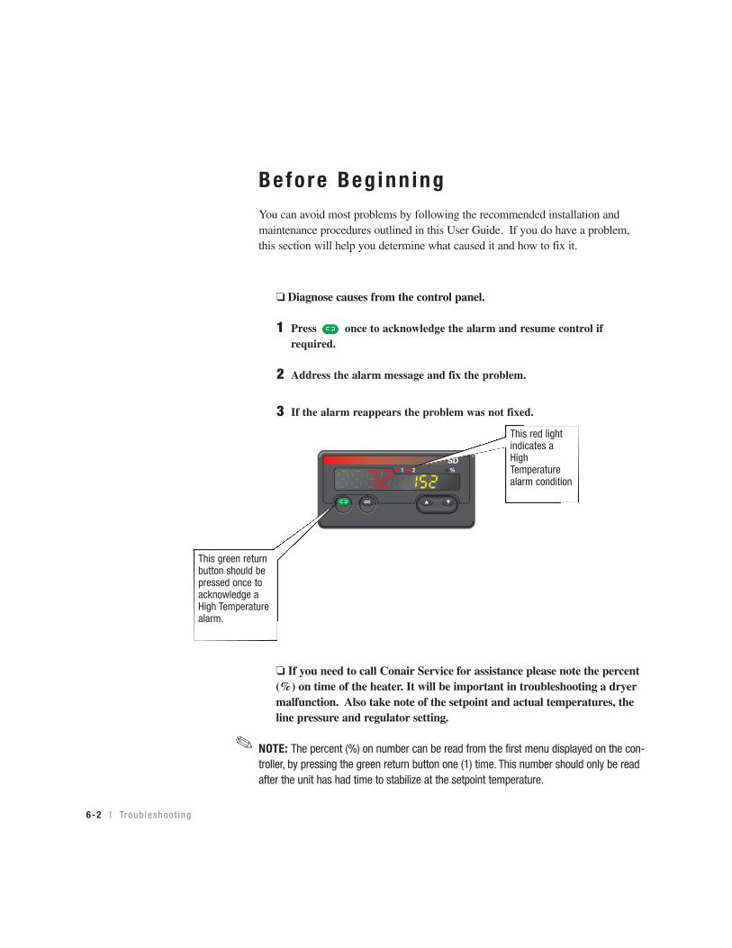
Before Beg inn ingYou can avoid most problems by following the recommended installation andmaintenance procedures outlined in this User Guide. If you do have a problem,this section will help you determine what caused it and how to fix it.
❏ Diagnose causes from the control panel.
1 Press once to acknowledge the alarm and resume control if required.
2 Address the alarm message and fix the problem.
3 If the alarm reappears the problem was not fixed.
❏ If you need to call Conair Service for assistance please note the percent(%) on time of the heater. It will be important in troubleshooting a dryermalfunction. Also take note of the setpoint and actual temperatures, theline pressure and regulator setting.
NOTE: The percent (%) on number can be read from the first menu displayed on the con-troller, by pressing the green return button one (1) time. This number should only be readafter the unit has had time to stabilize at the setpoint temperature.
1 2 %
SD
This red light indicates aHighTemperaturealarm condition
This green return button should bepressed once toacknowledge aHigh Temperaturealarm.
6-2 l Tr oub leshoo t i ng
✐
(continued)
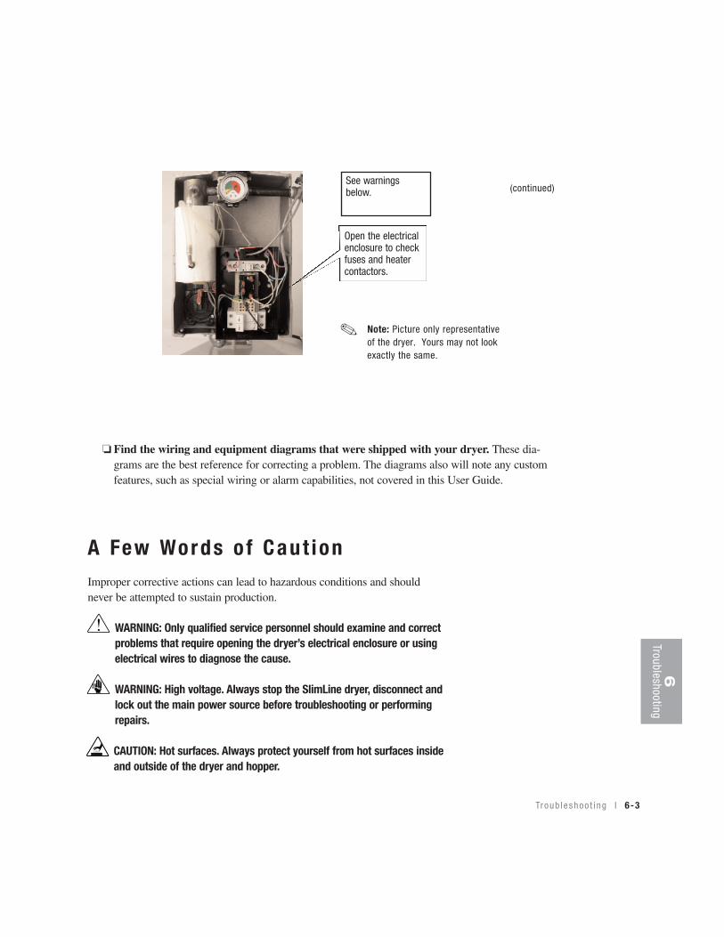
❏ Find the wiring and equipment diagrams that were shipped with your dryer. These dia-grams are the best reference for correcting a problem. The diagrams also will note any custom features, such as special wiring or alarm capabilities, not covered in this User Guide.
6Troubleshooting
A Few Words o f Caut ionImproper corrective actions can lead to hazardous conditions and shouldnever be attempted to sustain production.
WARNING: Only qualified service personnel should examine and correctproblems that require opening the dryer’s electrical enclosure or usingelectrical wires to diagnose the cause.
WARNING: High voltage. Always stop the SlimLine dryer, disconnect andlock out the main power source before troubleshooting or performingrepairs.
CAUTION: Hot surfaces. Always protect yourself from hot surfaces insideand outside of the dryer and hopper.
Troub leshoo t i ng l 6-3
See warningsbelow.
Open the electricalenclosure to checkfuses and heater contactors.
Note: Picture only representativeof the dryer. Yours may not lookexactly the same.
✐
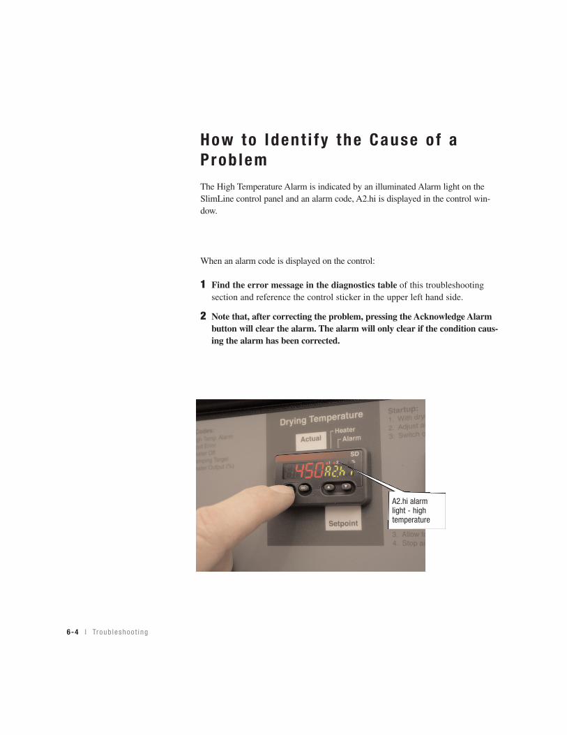
How to Iden t i f y the Cause o f aProb lemThe High Temperature Alarm is indicated by an illuminated Alarm light on theSlimLine control panel and an alarm code, A2.hi is displayed in the control win-dow.
When an alarm code is displayed on the control:
1 Find the error message in the diagnostics table of this troubleshootingsection and reference the control sticker in the upper left hand side.
2 Note that, after correcting the problem, pressing the Acknowledge Alarmbutton will clear the alarm. The alarm will only clear if the condition caus-ing the alarm has been corrected.
6-4 l Tr oub leshoo t i ng
A2.hi alarm light - high temperature

Troub leshoo t i ng l 6-5
A la rmsA problem can trigger two types of alarms:
• Latching Alarm : If the red Alarm LED is on, the alarm is a shutdown alarm. The dryer hasautomatically shut down because it detected a serious problem that could damage your material ordryer. Note that the Alarm must be acknowledged before the control will resume by pressing theinfinity button. See also Operation section entitled, Setting the High Temperature Setpoint.
• Cycling Alarm (internal safety devices): The dryer has two internal safety devices to avoidoverheating. A differential pressure switch which senses that there is low or no air flow and shuts theheater off, and a safety snap switch on the heater, that detects a high heater internal temperature.Both conditions will shut the heater off until the condition goes away or has been corrected, then thecontrol resumes. There is no signal to the operator for this condition.
ProblemA2.hi (alarm light illuminat-ed) – If the process tempera-ture exceeds the process hightemperature setpoint, it shutsdown the dryer. Default is setto 450°F (232°C).
Er.in – Input error
Possible causeOne of the process solid state relays hasfailed.
The air lines are restricted or loose.
The process setpoint is higher than thealarm setpoint.
The process output on the control hasfailed.
RTD (resistance temperature device) isnot providing acceptable range of resist-ance.
SolutionReplace the solid state relay. SeeTroubleshooting section entitled,Checking/Replacing Solid State Relays.
Straighten any crimps in the hoses.Tighten any loose hoses.
Set the process setpoint higher.
Replace the process controller.
Plug the RTD into the harness. See thewiring diagrams shipped with yourmachine.
Replace the RTD
Note: See the RTD resistance chart to determine if the sensor is bad. See Appendix C.
Repair electrical connections from theRTD to the controller. See the wiringdiagrams shipped with your machine.
6Troubleshooting
✐
Troub leshoot ing
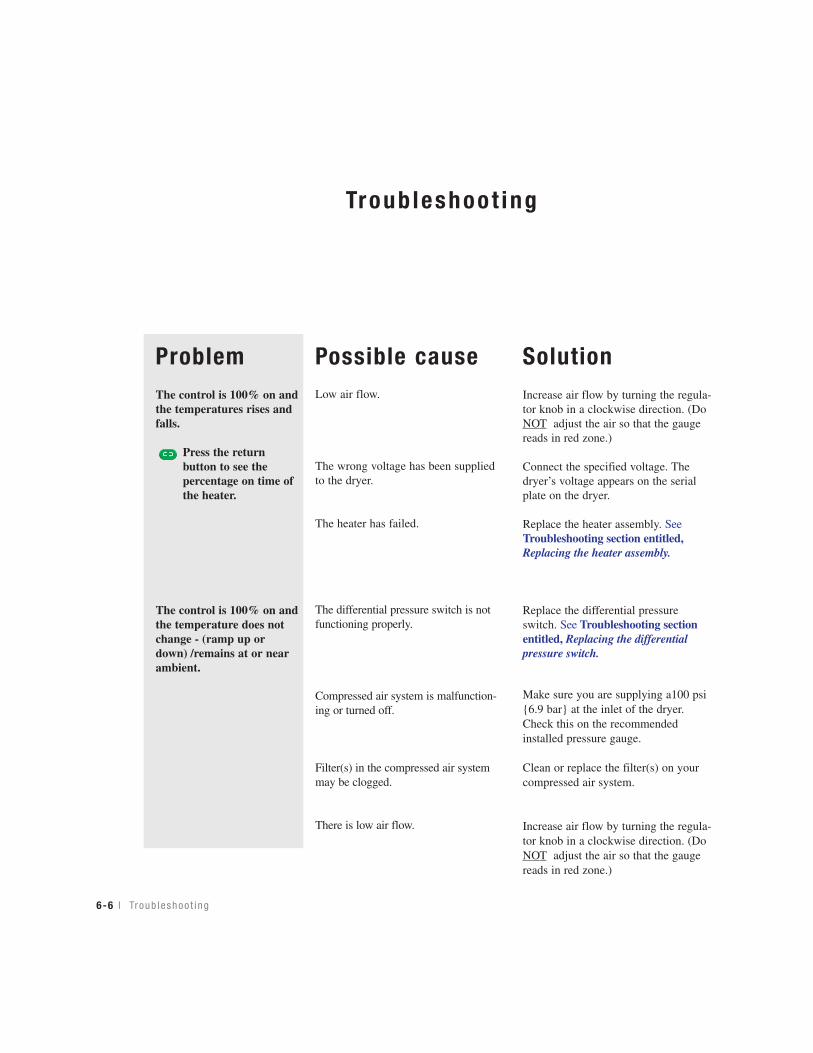
ProblemThe control is 100% on andthe temperatures rises andfalls.
Press the return button to see the percentage on time ofthe heater.
The control is 100% on andthe temperature does notchange - (ramp up ordown) /remains at or nearambient.
Possible causeLow air flow.
The wrong voltage has been suppliedto the dryer.
The heater has failed.
The differential pressure switch is notfunctioning properly.
Compressed air system is malfunction-ing or turned off.
Filter(s) in the compressed air systemmay be clogged.
There is low air flow.
SolutionIncrease air flow by turning the regula-tor knob in a clockwise direction. (DoNOT adjust the air so that the gaugereads in red zone.)
Connect the specified voltage. Thedryer’s voltage appears on the serialplate on the dryer.
Replace the heater assembly. SeeTroubleshooting section entitled,Replacing the heater assembly.
Replace the differential pressureswitch. See Troubleshooting sectionentitled, Replacing the differentialpressure switch.
Make sure you are supplying a100 psi{6.9 bar} at the inlet of the dryer.Check this on the recommendedinstalled pressure gauge.
Clean or replace the filter(s) on yourcompressed air system.
Increase air flow by turning the regula-tor knob in a clockwise direction. (DoNOT adjust the air so that the gaugereads in red zone.)
6-6 l Tr oub leshoo t i ng
Troub leshoot ing
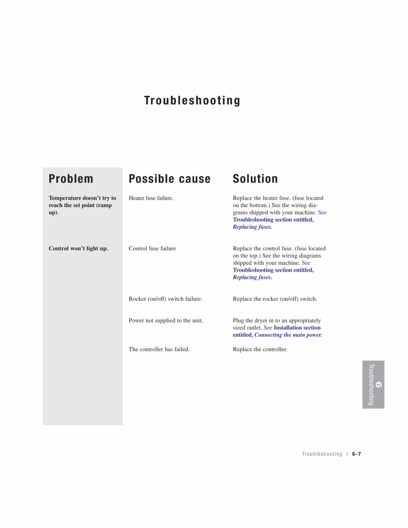
ProblemTemperature doesn’t try toreach the set point (rampup).
Control won’t light up.
Possible causeHeater fuse failure.
Control fuse failure
Rocker (on/off) switch failure.
Power not supplied to the unit.
The controller has failed.
SolutionReplace the heater fuse. (fuse locatedon the bottom.) See the wiring dia-grams shipped with your machine. SeeTroubleshooting section entitled,Replacing fuses.
Replace the control fuse. (fuse locatedon the top.) See the wiring diagramsshipped with your machine. SeeTroubleshooting section entitled,Replacing fuses.
Replace the rocker (on/off) switch.
Plug the dryer in to an appropriatelysized outlet. See Installation sectionentitled, Connecting the main power.
Replace the controller.
6Troubleshooting
Tr oub l eshoo t i ng l 6-7
6-8 l Tr oub leshoo t i ng
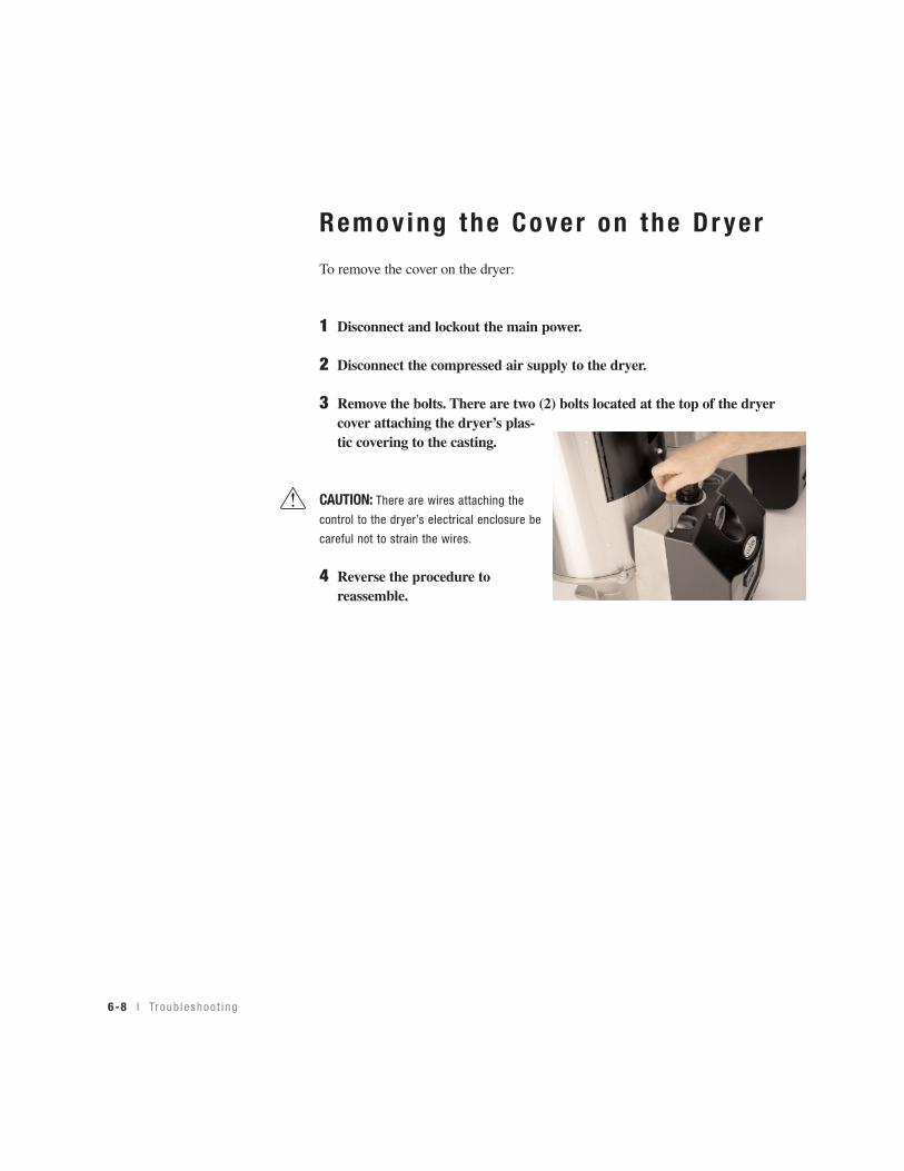
Remo v ing the Co ver on the Dr yer
To remove the cover on the dryer:
1 Disconnect and lockout the main power.
2 Disconnect the compressed air supply to the dryer.
3 Remove the bolts. There are two (2) bolts located at the top of the dryercover attaching the dryer’s plas-tic covering to the casting.
CAUTION: There are wires attaching the
control to the dryer’s electrical enclosure be
careful not to strain the wires.
4 Reverse the procedure toreassemble.

Troub leshoo t i ng l 6-9
Rep lac ing Fuses1 Unplug the main power supply.
2 Remove the dryer’s cover. SeeTroubleshooting section entitled,Removing the cover on the dryer.
3 Check the fuse. If necessary, pull thefuse out and replace it with a fuse of thesame type and rating.
CAUTION: Always disconnect and lock out the main power sources before making electrical connections. Electrical connections should be made only by qualified personnel.
Fuse BlocksTo locate the appropriate fuseand replacement part number,refer to the wiring diagramsthat came with your dryer.
IMPORTANT: Always referto the wiring diagrams thatcame with your dryer tolocate specific electricalcomponents. Illustrations inthe User Guide are intendedto be representative only.
6Troubleshooting
NOTE: Fuses have low resistance, if afuse has infinity resistance it is blown.Fuses must be replaced with a fuse ofthe same rating.
✐
Fuses - in service
Fuse blocks open for service.
6-10 l Tr oub leshoo t i ng
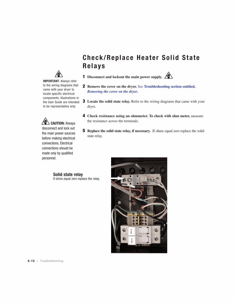
Check/Rep lace Hea te r So l id S ta teRe lays1 Disconnect and lockout the main power supply.
2 Remove the cover on the dryer. See Troubleshooting section entitled,Removing the cover on the dryer.
3 Locate the solid state relay. Refer to the wiring diagrams that came with yourdryer.
4 Check resistance using an ohmmeter. To check with ohm meter, measurethe resistance across the terminals.
5 Replace the solid state relay, if necessary. If ohms equal zero replace the solidstate relay.
IMPORTANT: Always referto the wiring diagrams thatcame with your dryer tolocate specific electricalcomponents. Illustrations inthe User Guide are intendedto be representative only.
Solid state relayIf ohms equal zero replace the relay.
CAUTION: Alwaysdisconnect and lock outthe main power sourcesbefore making electricalconnections. Electricalconnections should bemade only by qualifiedpersonnel.
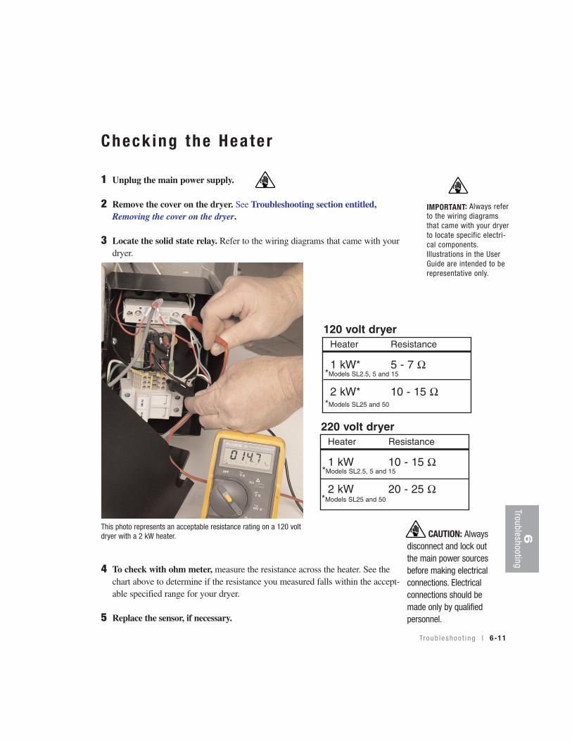
Check ing the Hea te r
1 Unplug the main power supply.
2 Remove the cover on the dryer. See Troubleshooting section entitled,Removing the cover on the dryer.
3 Locate the solid state relay. Refer to the wiring diagrams that came with yourdryer.
4 To check with ohm meter, measure the resistance across the heater. See thechart above to determine if the resistance you measured falls within the accept-able specified range for your dryer.
5 Replace the sensor, if necessary.
IMPORTANT: Always referto the wiring diagramsthat came with your dryerto locate specific electri-cal components.Illustrations in the UserGuide are intended to berepresentative only.
Troub leshoo t i ng l 6-11
6Troubleshooting
Heater Resistance
1 kW* 5 - 7 Ω
2 kW* 10 - 15 Ω
120 volt dryer
Heater Resistance
1 kW 10 - 15 Ω
2 kW 20 - 25 Ω
220 volt dryer
This photo represents an acceptable resistance rating on a 120 voltdryer with a 2 kW heater.
*Models SL2.5, 5 and 15
*Models SL25 and 50
*Models SL2.5, 5 and 15
*Models SL25 and 50
CAUTION: Alwaysdisconnect and lock outthe main power sourcesbefore making electricalconnections. Electricalconnections should bemade only by qualifiedpersonnel.
Rep lac ing the Hea te r Assembly
1 Disconnect and lockout the main power. If you have mounted a loader or vac-uum receiver on the hopper, disconnect the material inlet hose at the source.
2 Disconnect the compressed air supplied to the dryer.
3 Remove the dryer’s plastic cover. Remove two screws securing the cover inplace. IMPORTANT! Be sure to support the cover so that you do not strainthe wiring on the back of the control.
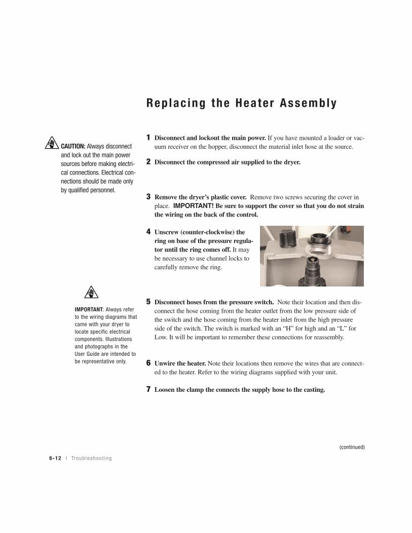
4 Unscrew (counter-clockwise) thering on base of the pressure regula-tor until the ring comes off. It maybe necessary to use channel locks tocarefully remove the ring.
5 Disconnect hoses from the pressure switch. Note their location and then dis-connect the hose coming from the heater outlet from the low pressure side ofthe switch and the hose coming from the heater inlet from the high pressureside of the switch. The switch is marked with an “H” for high and an “L” forLow. It will be important to remember these connections for reassembly.
6 Unwire the heater. Note their locations then remove the wires that are connect-ed to the heater. Refer to the wiring diagrams supplied with your unit.
7 Loosen the clamp the connects the supply hose to the casting.
(continued)
6-12 l Tr oub leshoo t i ng
IMPORTANT: Always referto the wiring diagrams thatcame with your dryer tolocate specific electricalcomponents. Illustrationsand photographs in theUser Guide are intended tobe representative only.
CAUTION: Always disconnectand lock out the main powersources before making electri-cal connections. Electrical con-nections should be made onlyby qualified personnel.
Rep lac ing the Hea te r Assembly(continued)
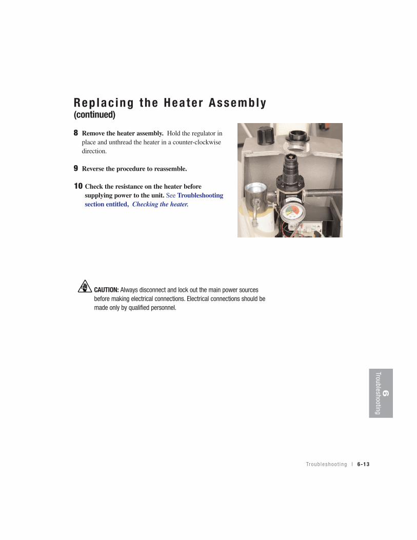
8 Remove the heater assembly. Hold the regulator in place and unthread the heater in a counter-clockwisedirection.
9 Reverse the procedure to reassemble.
10 Check the resistance on the heater before supplying power to the unit. See Troubleshootingsection entitled, Checking the heater.
6Troubleshooting
Tr oub l eshoo t i ng l 6-13
CAUTION: Always disconnect and lock out the main power sourcesbefore making electrical connections. Electrical connections should bemade only by qualified personnel.
Rep lac ing the A i r f l ow D i f fe ren t ia lP ressure Swi tch
1 Disconnect and lockout the main power. If you have mounted a loader or vac-uum receiver on the hopper, disconnect the material inlet hose at the source.
2 Disconnect the compressed air supplied to the dryer.
3 Remove the dryer’s plastic cover. Remove two screws securing the cover inplace. IMPORTANT! Be sure to support the cover so that you do not strainthe wiring on the back of the control.
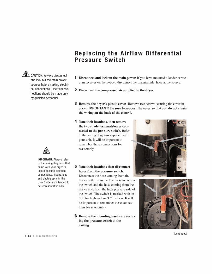
4 Note their locations, then removethe two spade terminals/wires con-nected to the pressure switch. Referto the wiring diagrams supplied withyour unit. It will be important toremember these connections forreassembly.
5 Note their locations then disconnecthoses from the pressure switch.Disconnect the hose coming from theheater outlet from the low pressure side ofthe switch and the hose coming from theheater inlet from the high pressure side ofthe switch. The switch is marked with an“H” for high and an “L” for Low. It willbe important to remember these connec-tions for reassembly.
6 Remove the mounting hardware secur-ing the pressure switch to the casting.
(continued)6-14 l Tr oub leshoo t i ng
IMPORTANT: Always referto the wiring diagrams thatcame with your dryer tolocate specific electricalcomponents. Illustrationsand photographs in theUser Guide are intended tobe representative only.
CAUTION: Always disconnectand lock out the main powersources before making electri-cal connections. Electrical con-nections should be made onlyby qualified personnel.
Rep lac ing the A i r f l ow D i f fe ren t ia lP ressure Swi tch (continued)
8 Connect the hose coming from the heater outlet to the low pressure sideof the switch and the hose coming from the heater inlet to the high pressure side of the switch.
9 Connect the two wires to their original location on the pressure switch.
10 Test the system. Make sure that the new air flow differential switch is detecting the pressure drop between the heater inlet and outlet.
11 Reinstall the cover on the closure.
6Troubleshooting
Tr oub l eshoo t i ng l 6-15
IMPORTANT: Alwaysrefer to the wiring dia-grams that came withyour dryer before mak-ing electrical connec-tions.
CAUTION: Always disconnect and lock out the main power sourcesbefore making electrical connections. Electrical connections should bemade only by qualified personnel.

6-16 l Tr oub leshoo t i ng
We’re Here to He lpConair has made the largest investment in customer support in the plastics indus-try. Our service experts are available to help with any problem you might haveinstalling and operating your equipment. Your Conair sales representative also can help analyze the nature of your problem, assuring that it did not result frommisapplication or improper use.
How to Contac t Cus tomer Ser v iceTo contact Customer Service personnel, call:
From outside the United States, call: 814-437-6861
You can commission Conair service personnel to provide on-site service by con-tacting the Customer Service Department.
Before You Ca l l . . .If you do have a problem, please complete the following checklist before calling Conair:
❒ Make sure you have all model, serial and parts list numbers for your particularequipment. Service personnel will need this information to assist you.
❒ Make sure power is supplied to the equipment.
❒ Make sure that all connectors and wires within and between control systemsand related components have been installed correctly.
❒ Check the troubleshooting guide of this manual for a solution.
❒ Thoroughly examine the instruction manual(s) for associated equipment, especial-ly controls. Each manual may have its own troubleshooting guide to help you.
❒ Check that the equipment has been operated as described in this manual.
❒ Check accompanying schematic drawings for information on special considerations.
Additional manuals and prints foryour Conair equipment may beordered through the CustomerService or Parts Department for anominal fee. Most manuals canbe downloaded free of chargefrom the product section of theConair website.www.conairnet.com.
A ppend i x l A-1
NOTE: Normal operating hours are 8:00 am - 5:00 PM. After hours emergencyservice is available at the same phone number.
✐

Equ ipment Guaran teeConair guarantees the machinery and equipment on this order, for a period asdefined in the quotation from date of shipment, against defects in material andworkmanship under the normal use and service for which it was recommended(except for parts that are typically replaced after normal usage, such as filters, liner plates, etc.). Conair’s guarantee is limited to replacing, at our option, the partor parts determined by us to be defective after examination. The customer assumesthe cost of transportation of the part or parts to and from the factory.
Per fo rmance War ran tyConair warrants that this equipment will perform at or above the ratings stated inspecific quotations covering the equipment or as detailed in engineering specifica-tions, provided the equipment is applied, installed, operated and maintained in therecommended manner as outlined in our quotation or specifications.
Should performance not meet warranted levels, Conair at its discretion will exercise one of the following options:
• Inspect the equipment and perform alterations or adjustments to satisfy performance claims. (Charges for such inspections and corrections will bewaived unless failure to meet warranty is due to misapplication, improper installation, poor maintenance practices or improper operation.)
• Replace the original equipment with other Conair equipment that will meet original performance claims at no extra cost to the customer.
• Refund the invoiced cost to the customer. Credit is subject to prior notice by thecustomer at which time a Return Goods Authorization Number (RGA) will beissued by Conair’s Service Department. Returned equipment must be well cratedand in proper operating condition, including all parts. Returns must be prepaid.
Purchaser must notify Conair in writing of any claim and provide a customer receiptand other evidence that a claim is being made.
Warranty L imi ta t ionsExcept for the Equipment Guarantee and Performance Warranty statedabove, Conair disclaims all other warranties with respect to the equipment,express or implied, arising by operation of law, course of dealing, usage oftrade or otherwise, including but not limited to the implied warranties ofmerchantability and fitness for a particular purpose.
A-2 l A ppend i x
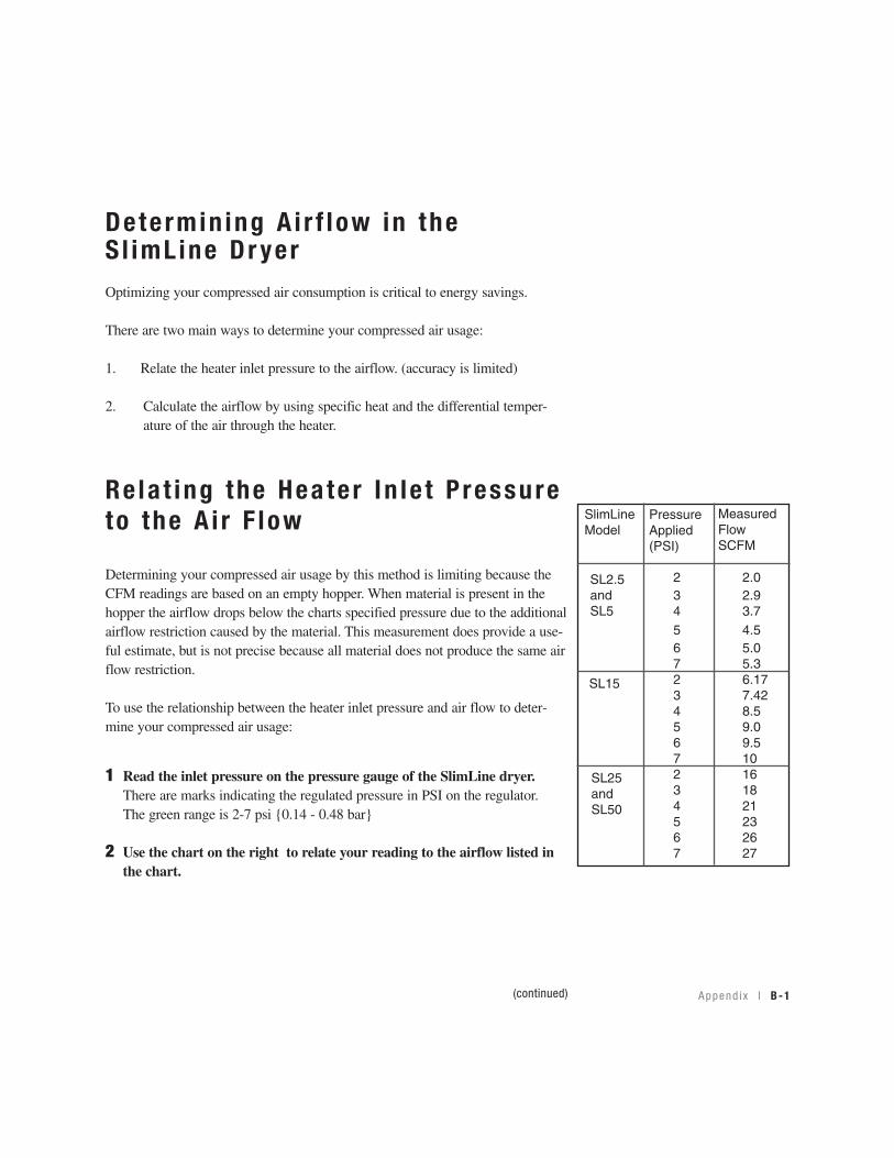
Determin ing A i r f l ow in theS l imL ine Dr yerOptimizing your compressed air consumption is critical to energy savings.
There are two main ways to determine your compressed air usage:
1. Relate the heater inlet pressure to the airflow. (accuracy is limited)
2. Calculate the airflow by using specific heat and the differential temper- ature of the air through the heater.
Re la t ing the Hea te r In le t P ressureto the A i r F low
Determining your compressed air usage by this method is limiting because theCFM readings are based on an empty hopper. When material is present in thehopper the airflow drops below the charts specified pressure due to the additionalairflow restriction caused by the material. This measurement does provide a use-ful estimate, but is not precise because all material does not produce the same airflow restriction.
To use the relationship between the heater inlet pressure and air flow to deter-mine your compressed air usage:
1 Read the inlet pressure on the pressure gauge of the SlimLine dryer.There are marks indicating the regulated pressure in PSI on the regulator. The green range is 2-7 psi {0.14 - 0.48 bar}
2 Use the chart on the right to relate your reading to the airflow listed inthe chart.
(continued)
SlimLineModel
PressureApplied(PSI)
Measured Flow SCFM
2 2.03 2.94 3.75 4.56 5.07 5.32 6.173 7.424 8.55 9.06 9.57 102 163 184 215 236 267 27
A ppend i x l B-1
SL2.5and SL5
SL15
SL25andSL50

Ca lcu la t ing the A i r f l ow th rough theHopper to Spec i fy the Mass o f A i rThe most accurate way calculate your airflow is to determine how much the tem-perature is increased by the actual heat input.
To specify the mass or air use the following equation:
Q = M * C * (Tout - Tin) where Q is the heat input, M is the mass of the air, C isthe specific heat or air and Tin, Tout are the temperature in and out of the heaterrespectively.
Then rearranging and adding units:
1 SCFM = (% on * Kw * 3413)/(0.075 * 60 * 0.24 * (Tout -Tin) )/100
2 SCFM = (% on * 31.08/Tout - Tin) for the SL 2.5/5/15
3 SCFM = (%on * 62.16)/(Tout -Tin) for the SL25/50
NOTE:
The percent (%) on number can be read from the first menu displayed on the con-troller, by pressing the green return button one (1) time. This number should only beread after the unit has had time to stabilize at the setpoint temperature.
Tout (temperature out)- the setpoint temperature (°F)
Tin (temperature in) - The compressed air supply temperature to the dryer (usuallyclose to the ambient temperature) (°F)
SCFM - Air flow in cubic feet per minute of air at standard density (0.075 lb/ft^3).
✐
B-2 l A ppend i x

RTD res is tance char tYou can use the following chart to determine if you need to replace your RTD.
A ppend i x l C-1
Compressed A i r Membrane Opt ion
This option is necessary when the compressed air supplied does not meet the 40º F {4º C} dewpoint. The membrane serves as a refrigerant air conditioner andreduces the dewpoint to the 40º F {4º C} dewpoint specification. The includedfilters aid in cleaning the compressed air.
The membrane is specifically designed to remove water vapor. Dryer perform-ance and life will be reduced if liquid water or liquid compressor oil enters thedryer. Filter(s) must be installed in front of the dryer to remove both liquid waterand oil aerosols if present in your plant's compressed air system.
Prepar ing to Ins ta l l the Membrane1 The membrane assembly can be used with oil lubricated, water lubricat-
ed or non-lubricated compressors.
2 Always install a drainable drip leg prior to the inlet filtration to the membrane assembly. This helps prevent the accumulation of water at lowpoints that could overwhelm the water handling capability of the filter.
3 Before installing the membrane assembly verify that:
a. The maximum pressure that could be encountered is less than the dryer150 psi {10.3 bar} and filter rated pressure.
b. The compressed air supply temperature and ambient temperature at themembrane assembly will not exceed 150º F {66º C}.
c. The dryer sweep air (located at the bottom of the longest membrane con-tainer) will not be obstructed.
d. The line sizes are adequate for the air flow and allowable pressure drop(Adequate size would be the same size as dryer or larger.)
(continued)
Replacement filters areavailable from Conair.
Contact Conair Parts 1 800 458 1960From outside of the UnitedStates, call:814 437 6861
D-1 l A ppend i x
CAUTION: Air under highpressure
This equipment uses com-pressed air delivered atrates up to 150 PSI{10.3 bar} to dry plasticmaterials.
To prevent possible injury,wear eye protection whenoperating this equipment.Always disconnect the com-pressed air supply beforeperforming maintenance ortroubleshooting.

Prepar ing to Ins ta l l the Membrane(continued)
4 The membrane option and any related prefiltration equipment isdesigned to be mounted in a vertical position. In most cases, we do not rec-ommend supporting the module with the process piping. We recommend pip-ing supports be located on either side of, directly in front of, or behind thedryer and filters. Support brackets are supplied with the membrane assemblyto simplify your installation.
Us ing the Wa l l Mount Bracke ts toMount the Membrane Assembly
The membrane assembly is supplied with wall mounting brackets. If you chooseto use the supplied mounting brackets:
1 Mount bracket to filter head. Remove four (4) screws holdingblack plastic top cap to filterhead. Then, place bracket on filterhead over plastic cap. Install screw supplied with bracket.
CAUTION: You are responsible for the structural integrity of this installation.
NOTE: It is important for maximum membrane life, that the appropriate fil-tration system be used with the membrane and the dryer. Proper prefiltra-tion will ensure the effective removal of particulates, water, compressorlubricant oil, and other types of contaminants. This is best accomplished bythe use of the integrated pre-filtration. Damage to the membrane and/orthe dryer or dew point degradation may result if the prefiltration isremoved or relocated at a distance away from the installation.
✐
A ppend i x l D-2
Mount ing the D i f fe ren t ia l P ressureGauge to the F i l t e rhead ( i f no t fac to r y ins ta l l ed )
1 Make certain o-rings are in place on the bottom of the gauge body.
2 Connect the low pressure transmission bolt (bolt next to the red band ongauge) to the gauge port at the filter outlet (downstream side of the fil-ter).
3 Connect the high pressure transmission bolt (bolt next to green band ongauge) to the gauge port at the filter inlet (upstream side of filter).
4 Use a flathead screwdriver to tighten/loosen bolts. The tip width of thescrewdriver should be a least 3/8 inch {9.5 mm}. Torque bolts to 25 +/- 5 inch oz. Do not overtighten.
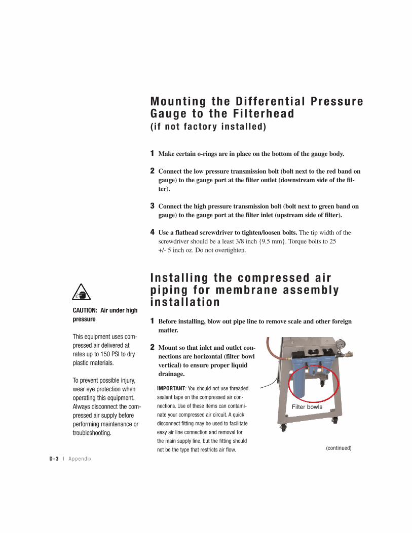
I ns ta l l i ng the compressed a i r p ip ing fo r membrane assemblyins ta l l a t ion1 Before installing, blow out pipe line to remove scale and other foreign
matter.
2 Mount so that inlet and outlet con-nections are horizontal (filter bowlvertical) to ensure proper liquiddrainage.
Filter bowls
D-3 l A ppend i x
IMPORTANT: You should not use threaded
sealant tape on the compressed air con-
nections. Use of these items can contami-
nate your compressed air circuit. A quick
disconnect fitting may be used to facilitate
easy air line connection and removal for
the main supply line, but the fitting should
not be the type that restricts air flow. (continued)
CAUTION: Air under highpressure
This equipment uses com-pressed air delivered atrates up to 150 PSI to dryplastic materials.
To prevent possible injury,wear eye protection whenoperating this equipment.Always disconnect the com-pressed air supply beforeperforming maintenance ortroubleshooting.

I ns ta l l i ng the compressed a i r p ip ing fo r membrane assemblyins ta l l a t ion (continued)
4 Install so that the air flow direction is in the direction ofarrows on the filterhead.
NOTE: Make certain flow direction through filters is correct(observe pin hole used for aligning top caps). When hole is onside closest to you, inlet is to left.
5 For ease of service, Conair recommends that an isola-tion valve (not included) is installed on the compressedair line leading to the membrane assembly.
Membrane Ins ta l l a t ion
1 A typical membrane assembly installation is shown below.
Isolation valve installationrecommended(not included)
A ppend i x l D-4
CAUTION: Always wear pro-tective eyewear when work-ing with compressed air.
Airflow direction
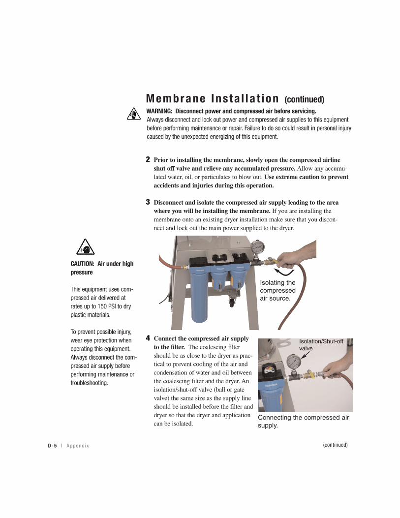
Membrane Ins ta l l a t ion (continued)
2 Prior to installing the membrane, slowly open the compressed airline shut off valve and relieve any accumulated pressure. Allow any accumu-lated water, oil, or particulates to blow out. Use extreme caution to prevent accidents and injuries during this operation.
3 Disconnect and isolate the compressed air supply leading to the area where you will be installing the membrane. If you are installing the membrane onto an existing dryer installation make sure that you discon-nect and lock out the main power supplied to the dryer.
4 Connect the compressed air supplyto the filter. The coalescing filtershould be as close to the dryer as prac-tical to prevent cooling of the air andcondensation of water and oil betweenthe coalescing filter and the dryer. Anisolation/shut-off valve (ball or gatevalve) the same size as the supply lineshould be installed before the filter anddryer so that the dryer and applicationcan be isolated.
Isolating thecompressedair source.
Isolation/Shut-offvalve
Connecting the compressed airsupply.
D-5 l A ppend i x (continued)
WARNING: Disconnect power and compressed air before servicing.Always disconnect and lock out power and compressed air supplies to this equipmentbefore performing maintenance or repair. Failure to do so could result in personal injurycaused by the unexpected energizing of this equipment.
CAUTION: Air under highpressure
This equipment uses com-pressed air delivered atrates up to 150 PSI to dryplastic materials.
To prevent possible injury,wear eye protection whenoperating this equipment.Always disconnect the com-pressed air supply beforeperforming maintenance ortroubleshooting.
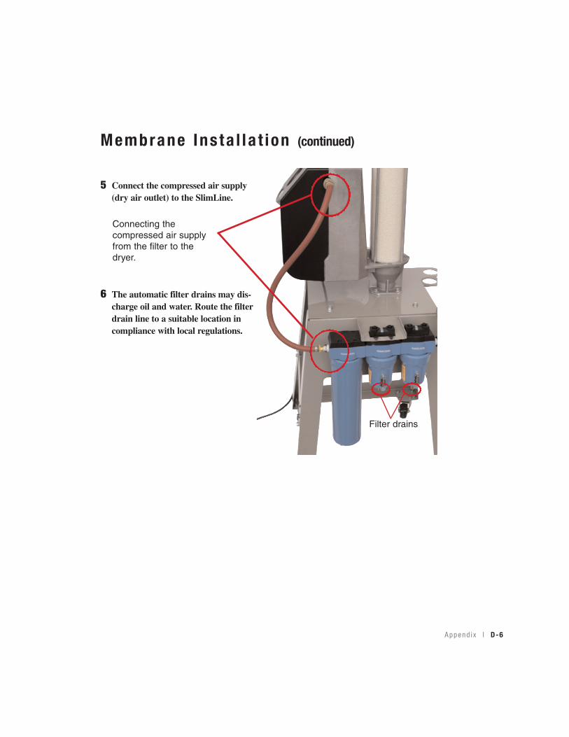
Membrane Ins ta l l a t ion (continued)
5 Connect the compressed air supply(dry air outlet) to the SlimLine.
6 The automatic filter drains may dis-charge oil and water. Route the filterdrain line to a suitable location incompliance with local regulations.
Connecting thecompressed air supplyfrom the filter to thedryer.
Filter drains
A ppend i x l D-6
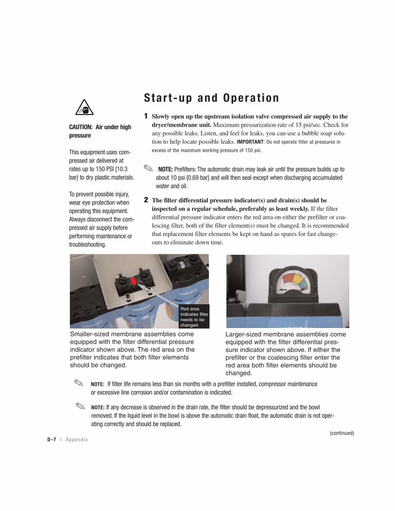
Star t -up and Opera t ion1 Slowly open up the upstream isolation valve compressed air supply to the
dryer/membrane unit. Maximum pressurization rate of 15 psi/sec. Check forany possible leaks. Listen, and feel for leaks, you can use a bubble soap solu-tion to help locate possible leaks. IMPORTANT: Do not operate filter at pressures in
excess of the maximum working pressure of 150 psi.
2 The filter differential pressure indicator(s) and drain(s) should be inspected on a regular schedule, preferably as least weekly. If the filter differential pressure indicator enters the red area on either the prefilter or coa-lescing filter, both of the filter element(s) must be changed. It is recommendedthat replacement filter elements be kept on hand as spares for fast change- outs to eliminate down time.
NOTE: Prefilters: The automatic drain may leak air until the pressure builds up toabout 10 psi {0.69 bar} and will then seal except when discharging accumulatedwater and oil.
✐
NOTE: If filter life remains less than six months with a prefilter installed, compressor maintenanceor excessive line corrosion and/or contamination is indicated.
✐
NOTE: If any decrease is observed in the drain rate, the filter should be depressurized and the bowlremoved. If the liquid level in the bowl is above the automatic drain float, the automatic drain is not oper-ating correctly and should be replaced.
✐
Smaller-sized membrane assemblies comeequipped with the filter differential pressureindicator shown above. The red area on theprefilter indicates that both filter elementsshould be changed.
Larger-sized membrane assemblies comeequipped with the filter differential pres-sure indicator shown above. If either theprefilter or the coalescing filter enter thered area both filter elements should bechanged.
Red area indicates filterneeds to bechanged.
D-7 l A ppend i x(continued)
CAUTION: Air under highpressure
This equipment uses com-pressed air delivered atrates up to 150 PSI {10.3bar} to dry plastic materials.
To prevent possible injury,wear eye protection whenoperating this equipment.Always disconnect the com-pressed air supply beforeperforming maintenance ortroubleshooting.
Star t -up and Opera t ion (continued)
3 Filter element(s) should be replaced on a regular schedule (preferablyevery six months). See Appendix D section entitled, Filter ElementReplacement.
4 To shutdown the membrane assembly turn off the air supply and allowthe pressure to decrease to atmospheric. Maximum de-pressurization of 15psi/sec.
IMPORTANT: Do not operate filter at pressures in excess of the maximum working
pressure of 150 psi.
Main tenance and Troub leshoot ing
The only routine maintenance required is replacement of the filter element(s)every six months and rebuilding or replacing the drain mechanism annually.The are no repairable components within the membrane. The membrane mustbe replaced if damaged or oil soaked.
To ensure performance of the membrane and to obtain maximum compressorlife, all compressor maintenance schedules recommended by the compressormanufacturer should be followed.
A ppend i x l D-8
WARNING: Disconnect power and compressed air before servicing.Always disconnect and lock out power and compressed air supplies to thisequipment before performing maintenance or repair. Failure to do so couldresult in personal injury caused by the unexpected energizing of this equipment.
NOTE: Maximum operating temperature of the membrane assembly is150º F {38º C}.
✐
D-9 l A ppend i x
Main tenance/Troub leshoot ingCheckpo in tsCheck flow, pressure, and temperature to make certain filter is being operatedwithin design conditions.
• High dewpoint - Before attempting to troubleshoot the membrane veri-fy that the dry air flow rate is at or below the design level of the membrane assembly (150 psi {10.3 bar}). High air flow will result in high dew points.
The most likely cause of the high dew point is low air supply pres-sure, due to either low pressure to the filters or high pressure drop across the filters. The latter will be indicated by the filter differential pressure indicator.
Another possible cause of high dew point is failure of the automatic drains. Manually open the drain.
• Check pressure drop across the filterPressure differential in excess of 6 psi {0.41 bar} or pressure indi-cator in red area means that the filter sleeve or element should be replaced.
• Check for sudden reduction in pressure drop. This might indicate: A possible leak across element o-ring seal or a leak through the element due to physical damage.
• Check to see that filter is installed level to ensure proper drainage.
• Check that manual drains are drained periodically or that auto-matic drains are functioning.
• On models with liquid level sight glass check that liquid level is below top of sight glass.
NOTE: Pressure drop should never exceed 50 psi {3.4 bar}.✐
A ppend i x l D-10
F i l t e r E lementsIf the filter differential pressure indicator shows red, filter elements must bechanged. Continuing to operate for an extended period after the filter differentialpressure indicator(s) have changed completely to red could result in low air pres-sure, high dew points, and eventually in failure of the filter element leading tocontamination and damage of the dryer.
If filter element life remains less than six months with a prefilter installed, com-pressor maintenance or excessive line corrosion or contamination is indicated.
When to Rep lace a F i l t e r E lement
a. Initial (dry) pressure drop: 1 psi {0.07 bar} to 2 psi {0.14 bar}.
b. Operating pressure drop: As filter becomes liquid loaded (wetted), pressuredrop will increase to 2 to 6 psi {0.14 bar to 0.41 bar}. Further pressure dropoccurs as element loads with solid particles.
F i l t e r E lement Rep lacementThis filter is a pressure containing device. Depressurize before servicing isolateand completely depressurize filter before proceeding.
NOTE: Pressure dropmay temporarily increasewhen flow is resumedafter flow stoppage.Pressure drop shouldreturn to normal withinone hour.
✐
WARNING: Disconnect power and compressed air before servicing.Always disconnect and lock out power and compressed air supplies to thisequipment before performing maintenance or repair. Failure to do so could resultin personal injury caused by the unexpected energizing of this equipment.
(continued)
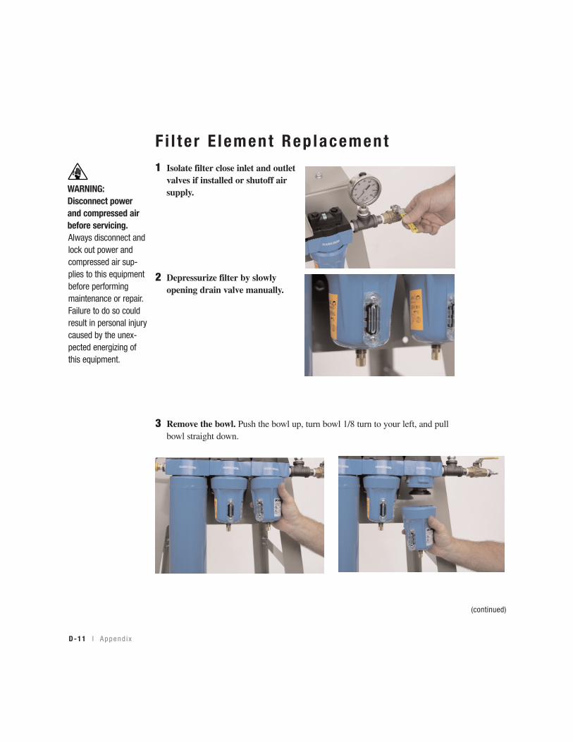
D-11 l A ppend i x
F i l t e r E lement Rep lacement1 Isolate filter close inlet and outlet
valves if installed or shutoff airsupply.
2 Depressurize filter by slowly opening drain valve manually.
3 Remove the bowl. Push the bowl up, turn bowl 1/8 turn to your left, and pullbowl straight down.
(continued)
WARNING:Disconnect powerand compressed airbefore servicing.Always disconnect andlock out power andcompressed air sup-plies to this equipmentbefore performingmaintenance or repair.Failure to do so couldresult in personal injurycaused by the unex-pected energizing ofthis equipment.
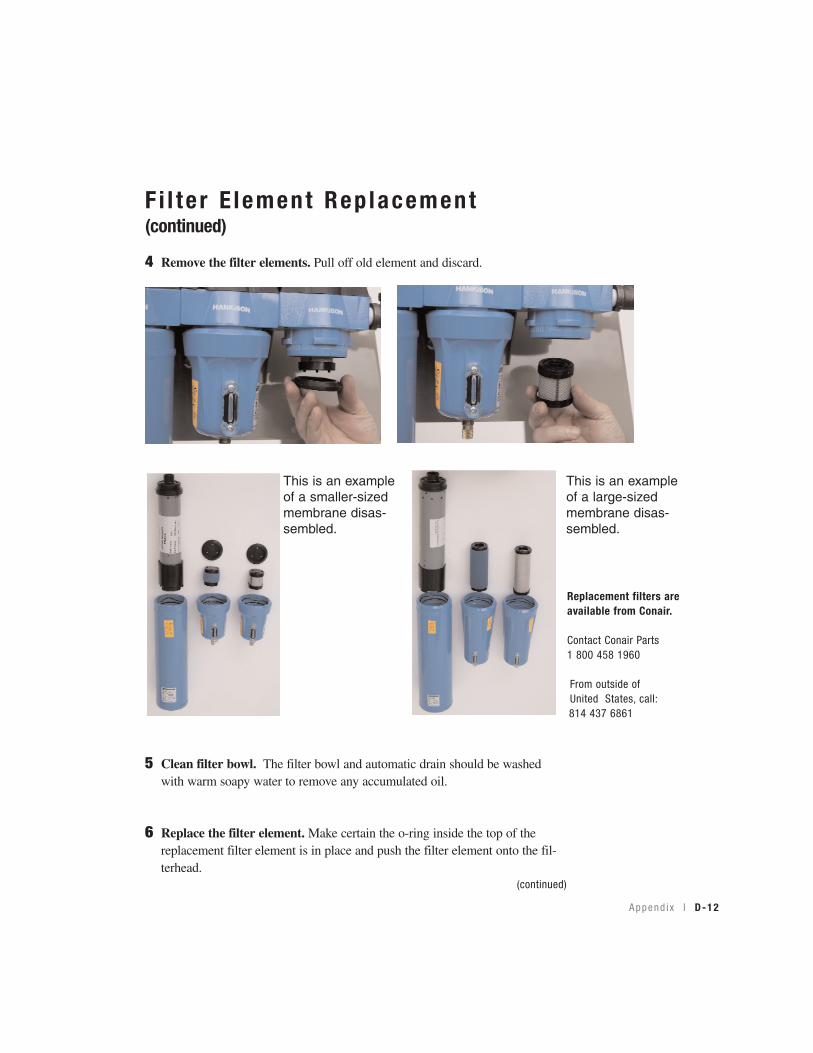
A ppend i x l D-12
(continued)
F i l t e r E lement Rep lacement (continued)
4 Remove the filter elements. Pull off old element and discard.
5 Clean filter bowl. The filter bowl and automatic drain should be washedwith warm soapy water to remove any accumulated oil.
6 Replace the filter element. Make certain the o-ring inside the top of thereplacement filter element is in place and push the filter element onto the fil-terhead.
This is an exampleof a smaller-sizedmembrane disas-sembled.
This is an exampleof a large-sizedmembrane disas-sembled.
Replacement filters areavailable from Conair.
Contact Conair Parts 1 800 458 1960
From outside of United States, call:814 437 6861

D-13 l A ppend i x
F i l t e r E lement Rep lacement (continued)
7 After making certain that o-ring inside top of bowl and the wave springare in place, reassemble bowl to head.
Automat ic Dra in ing Mechan ism
1 Membrane assemblies are equipped with automatic drains. Liquids willautomatically discharge when a sufficient accumulation occurs. Thesedrains may be manually drained by turning to your right (clockwise) to openand to your left (counterclockwise) to close.
NOTE: Do not handle elements by outside foam cover. Handle by bottomend cap only.
✐
NOTE: Make certain o-ring is generously lubricated.✐
NOTE: Wave spring ends should be pointed down to prevent wave springfrom interfering with reassembly.
✐
NOTE: Collected liquids must be removed to ensure properoperation.
✐
NOTE: Depressurize slowly, to avoid filter element damage.✐
✒Tip: Manually draininternal auto drains dailyto verify drain function.
IMPORTANT: If a high water level is observed in a filter liquid level indicator,the automatic drain is not functioning correctly. The dryer should be shutdown and the drain mechanism should be repaired or replaced before pro-ceeding. Extended operation with malfunctioning automatic drain(s) couldresult in liquid water and oil entering the dryer, resulting in elevated dewpoints and damage to the membrane assembly and/or dryer.
✒Tip: It is recommendedthat drain mechanism bereplaced annually.
A ppend i x l D-14
D ra in P ro v is ionsThe bottom of internal automatic drains are provided with 1/8 inch (insidethreads) for connection of a drain line if desired.
Discharge is at system pressure; anchor drain line