Embed Size (px)
Citation preview

43-TV-25-01 GLO Issue 3 01/01 UK
CircitrendMultitrendTeletrend
User Manual

43-TV-25-01 GLO Issue 3 01/01 UK

Table of Contents
Table of Contents iii
Chapter 1: Welcome to Honeywell V5 1
Safety .......................................................................................................................... 1Symbols .................................................................................................................. 1Static Electricity .................................................................................................... 1Dos and Don’ts ...................................................................................................... 2Hazardous Voltage ................................................................................................. 3
Introduction ............................................................................................................... 3
Description ................................................................................................................ 3
Specifications ............................................................................................................ 4
Chapter 2: Installation 5
Unpacking .................................................................................................................. 5
Mechanical ................................................................................................................ 5Teletrend V5/Multitrend V5 .................................................................................... 5Circitrend V5 ......................................................................................................... 6
Electrical .................................................................................................................... 6ac Power ................................................................................................................ 6dc Power ................................................................................................................ 7
Analogue Inputs ........................................................................................................ 7Standard Analogue Card ....................................................................................... 8Transmitter Power Supply ...................................................................................... 8
Universal Analogue Card ........................................................................................ 9
Alarm Outputs ........................................................................................................... 94 and 8 Relay Alarm Card ..................................................................................... 98 Input/Output Alarm Card .................................................................................. 10
Digital Inputs ........................................................................................................... 10
Serial Interface ........................................................................................................ 10
Chapter 3: Getting Started 11
Power Up ................................................................................................................. 11
Basic Keypad Operation ........................................................................................ 12Changing Display Modes .................................................................................... 12
Using Menus ........................................................................................................... 12
Entering Text ........................................................................................................... 13
Software Reset ........................................................................................................ 13
Circitrend V5 and Multitrend V5 Text Entry .................................................... 14
43-TV-25-01 GLO Issue 3 01/01 UK i i i

Chapter 4: Display Setup Menus 15
Layout .......................................................................................................................15
Display Formats ......................................................................................................17
Display Features ......................................................................................................18
Chapter 5: Circitrend V5 Features 19
Special Features ......................................................................................................19
Layout .......................................................................................................................20
Group Setups ...........................................................................................................21
Circular Charts ........................................................................................................22
Chapter 6: Pen Display 23
Teletrend V5 Pen Display Parameters .................................................................23
Circitrend V5 and Multitrend V5 Pen Display Parameters .............................24
Chapter 7: Unit Setups 27
Disk ...........................................................................................................................27
Unit Setup .................................................................................................................27
Unit ID ......................................................................................................................28
Time ..........................................................................................................................28
Chapter 8: Input to a Standard Analogue Card 29
Volts/Current ............................................................................................................30
Sample Subrange ....................................................................................................31
Square Root Extraction ..........................................................................................31
Input Engineering Units .........................................................................................31
Copy to ......................................................................................................................32
Chapter 9: Input to a Universal Analogue Card 33
Selecting Volts or Current .....................................................................................33
Thermocouples ........................................................................................................33
Chapter 10: Pen Setup Options 35
Pen Setup ..................................................................................................................35
Name .........................................................................................................................36
Scale ..........................................................................................................................36
Maths Expressions ..................................................................................................37
Log Method ..............................................................................................................38
Log Speed .................................................................................................................38
i v 43-TV-25-01 GLO Issue 3 01/01 UK

Alarms ...................................................................................................................... 39
High or Low Alarms .............................................................................................. 40Peaks .................................................................................................................... 40Hysteresis ............................................................................................................. 41Symmetrical ......................................................................................................... 41Damping .............................................................................................................. 41Relays ................................................................................................................... 42
Alarm Log Speed ................................................................................................... 42
Totaliser Setup ........................................................................................................ 43
Totaliser Log Interval ............................................................................................. 44
Markers .................................................................................................................... 44
Causes ...................................................................................................................... 45
Effects ....................................................................................................................... 46
Chapter 11: Special Setups 47
Chapter 12: Advanced Setups 51
Digitals ..................................................................................................................... 51
Session Start ............................................................................................................ 53
Circular Chart .......................................................................................................... 53
About ........................................................................................................................ 54
Chapter 13: Operation 55
Recording Data ....................................................................................................... 55
Replaying Data ....................................................................................................... 56Keypad Operation ................................................................................................ 56
Session Numbering ................................................................................................ 57
Chapter 14: Viewing Data 59
Softkey Operation .................................................................................................. 59QuickView ............................................................................................................ 59Add Marker .......................................................................................................... 60List Events ............................................................................................................ 61View Totals ........................................................................................................... 61Zoom Pen ............................................................................................................. 62Zoom Group ......................................................................................................... 62Freeze Frame (Pause) .......................................................................................... 63Display Off ........................................................................................................... 63
Screen Dumps ......................................................................................................... 63
Chapter 15: Disk Operations 65
Disk Full .................................................................................................................. 65
Disk Unformatted ................................................................................................... 66
43-TV-25-01 GLO Issue 3 01/01 UK v

Wiping Disks ...........................................................................................................66
Disk Faults ...............................................................................................................66Wrong Disk ...........................................................................................................66Disk Out ...............................................................................................................66Disk Read Error ...................................................................................................66
Chapter 16: Writing To Disk 67
Logged Data .............................................................................................................67
Setups Data ..............................................................................................................67
Screen Dumps ..........................................................................................................67
Totaliser ....................................................................................................................68
Event File .................................................................................................................68
Chapter 17: Options Key 69
Function One ...........................................................................................................69NV RAM ...............................................................................................................69
Function Two ...........................................................................................................69Maths Expressions ................................................................................................69Totalising ..............................................................................................................69Event Markers ......................................................................................................69Group ....................................................................................................................69
Chapter 18: TrendManager Pro 71
Introduction ..............................................................................................................71
Function ....................................................................................................................71
Data Archiving ........................................................................................................71
Communications .....................................................................................................71
Chapter 19: Maintenance 73
Cleaning ....................................................................................................................73
Disk Drives ..............................................................................................................73
Operating Temperature ..........................................................................................74
Front Panel ...............................................................................................................74
Keypad ......................................................................................................................74
Calibration ................................................................................................................74
Appendix A - Quality Approvals 75
Quality Assurance ...................................................................................................75
CE Mark ...................................................................................................................75
vi 43-TV-25-01 GLO Issue 3 01/01 UK

Appendix B - Transmitter Power Supply 77
Current Output Transmitters ................................................................................. 77
Voltage Output Transducers .................................................................................. 77
Appendix C - Signal Processing 79
Input Block .............................................................................................................. 80
Maths Expressions ................................................................................................. 80
Data List ................................................................................................................... 81
Totaliser .................................................................................................................... 81
Calibrating Analogue References ........................................................................ 82
Pen Scales ................................................................................................................ 82
Appendix D - Maths Expressions 85Boolean Expressions ............................................................................................ 88
Appendix E - Character List 89
Appendix F - Serial Interface Connections 91
RS485 Trendbus™ network ................................................................................. 91
RS485 Modbus™ network ................................................................................... 91
Appendix G - Thermocouple Connections 93
Internal Reference .................................................................................................. 93
External Reference @ 0 °C .................................................................................. 94
External Reference @ Specified Temperature .................................................. 94
External Input Reference ...................................................................................... 95
Appendix H - Calibrating Analogue References 97
Appendix J - Events 99
Appendix K - Barcode Reader 101
Introduction ........................................................................................................... 101
Installation ............................................................................................................. 101
Configuration ........................................................................................................ 101
Utilisation .............................................................................................................. 102
Operation ............................................................................................................... 102
Barcode Reader Test Procedure ......................................................................... 102
43-TV-25-01 GLO Issue 3 01/01 UK vi i

Appendix L - Battery Safety Data Sheet 103
Location : Processor Board .................................................................................103Safety Guideline .................................................................................................103
Index 105
vi i i 43-TV-25-01 GLO Issue 3 01/01 UK

Chapter 1: Welcome to Honeywell V5
SafetyThe Honeywell V5 range of instruments is compliant with the requirements of
BS EN 61010-1:1993 "Safety Requirements for Electrical Equipment forMeasurement, Control and Laboratory Use". If the equipment is used in a mannerNOT specified by Honeywell, the protection provided by the equipment may beimpaired.
SymbolsOne or more of the following symbols may appear on the recorder labelling
Static ElectricityAll circuit boards and electronic modules associated with this recorder contain
components which are susceptible to damage caused by electrostatic discharge.Should it be necessary to handle such components, appropriate precautions inaccordance with BS CECC 00015 "Basic specification: Protection of electrostaticsensitive devices" should be observed.
Symbol Meaning
Caution - refer to manual for instructions
Caution - risk of electric shock
Direct Current
Protective conductor terminal
Earth terminal
43-TV-25-01 GLO Issue 3 01/01 UK 1

Dos and Don’ts1. Before any other connections are made to the recorder, the protective earth terminal
shall be connected to a protective conductor.
WARNING
IMPROPER INSTALLATION
Any interruption of the protective conductor outside the recorder, or disconnection ofthe protective earth terminal is likely to make the recorder dangerous under some faultconditions. Intentional interruption of the protective conductor is prohibited.
In order to comply with the requirements of safety standard EN61010, the recordershall have one of the following as a disconnecting device, located within easy reach of theoperator, and clearly labelled as the disconnecting device:
• A switch or circuit breaker which complies with the requirements of IEC947-1and IEC947-3.
• A separable coupler which can be disconnected without the use of a tool.
• A separable plug, without a locking device, to mate with a socket outlet in thebuilding.
Failure to comply with these instructions could result in death or serious injury.
2. Whenever it is likely that protection has been impaired, the recorder shall be made inop-erative and secured against operation. The manufacturer's service centre should beconsulted.
3. Any adjustment, maintenance and repair of the opened recorder in a powered conditionis prohibited.
4. Where conductive pollution such as condensation or conductive dust is present, ade-quate air conditioning, filtering and/or sealing must be installed.
5. This recorder contains a battery which must be treated and disposed of with care. Thebattery must not be short circuited. Batteries should be disposed of in accordance withlocal regulations; they must not be disposed of with normal refuse.
WARNING
IMPROPER INSTALLATION
Signal and supply wiring should be kept separate from one another. Where this isimpractical, shielded cables should be used for the signal wiring. Where signal wiring iscarrying, or could carry under fault conditions, hazardous voltages (defined as > 30 V rmsand 42.4 V peak, or > 60 Vdc), double insulation must be used for all signal wiring.
Failure to comply with these instructions could result in death or serious injury.
6. If the equipment is used in a manner not specified by the manufacturer, the protectionprovided by the equipment might be impaired.
7. In the case of portable equipment, the protective earth terminal must remain connected(even if the recorder is isolated from the mains supply) if any of the measuring,communications or relay terminals are connected to hazardous voltages.
2 43-TV-25-01 GLO Issue 3 01/01 UK

Hazardous VoltageHazardous Voltages are defined by EN61010-1 as follows:
Voltage levels above 30 Vrms and 42.4 V peak or 60 Vdc are deemed to be HazardousLive.
Please refer to “Appendix L - Battery Safety Data Sheet” on page 103 for further infor-mation.
IntroductionHoneywell V5, the 'Next Generation' of paperless chart recorders, is the latest
development of the solid-state replacement for traditional paper chart recorders, originally pioneered by Honeywell in 1985.
Several options are available to meet a wide range of requirements within the water,process, gas and petrochemical industries, as well as power and environmentalmonitoring.
The Teltrend V5™, Multitrend V5™ and Circitrend V5™ all incorporate thin-filmtransistor LCD technology, data storage on 3.5" floppy disk, and universal powercapability. Depending on the model, a range of up to 9 traces can be displayed, with realtime bargraph and digital readouts - each input channel also has the option of two alarms.
Additional features include alarm relay outputs, digital inputs, totalising, event markers,maths expressions, network communications, barcode reading and user-defined screenlayouts.
Recorder configuration, export and archiving of data, trend analysis and printouts, andreal time communications with the recorder are all provided by the HoneywellTrendManager Pro™ software.
Description
Model Details
Teletrend V5™A 2, 4, 6 or 8 channel recorder with 5.5” LCD offering a low-cost version of the paperless chart recorder.
Multitrend V5™ A 6 or 8 channel recorder with 10.4” LCD for easier viewing from further distances.
Circitrend V5™ The first paperless circular chart recorder incorporating 2, 4, 6 or 8 channels and a 10.4” LCD, with a panel-mounted or sealed-enclosure option.
43-TV-25-01 GLO Issue 3 01/01 UK 3
Specifications
Panel depth measurements do not include the thickness of the panel.
Teletrend V5™ Multitrend V5™ Circitrend V5™
Display Technology 5.5" TFT LCD 10.4" TFT LCD 10.4 " TFT LCD
Data Storage 3.5” 1.44 Mbyte floppy disk
Dimensions (mm) :Bezel Size (w x h)
Panel DepthPanel cut out
144x144300
138x138
231x239300
138x138
350x350150
322x322
Number of Channels 2, 4, 6 or 8 6 or 8 2,4, 6 or 8
Input SignalsStandard
0-20 mA, 4-20 mA, 0-5 Vdc or specified sub-ranges
Universal Inputs Option±100 mV, ±200 mV, ±1 V, ±10 V, ±10 mA, ±20 mA,
PT100, Thermocouple
Resolution Standard analogue - 0.1 %; Universal analogue - 0.0015 %
ac Power Supply85-250 Vac50-60 Hz
85-250 Vac50-60 Hz
85-250 Vac50-60 Hz
dc Power Supply 9 - 18 V, 18 - 36 V, 36 - 72 V
Power Consumption (max)27 VA(ac), 27 W(dc)
50 VA(ac), 50 W(dc)
Alarms 2 per channel Optional on all models - 3 A, 240 Vac relays.
Communications Optional isolated RS485 or barcode reader.
Trendbus™ or Modbus™ protocols for remote data retrieval.
dc Isolation >90 V
Relative Humidity 10 % to 90 % RH
Operating Temp 0 to 50 °C
Storage Temp -10 to 60 °C
4 43-TV-25-01 GLO Issue 3 01/01 UK

Chapter 2: Installation
UnpackingIt is advisable to retain the packaging in which your recorder arrives, including
the styrofoam packing, should the need to return your recorder arise. If the originalpacking is destroyed, then ONLY pack the recorder in polystyrene granules if therecorder is FIRST sealed in a strong plastic bag.
Mechanical
Teletrend V5/Multitrend V5These units are all panel mounted in the same manner as shown in below. The
recorder slides into the panel cut-out from the front and is held in place by twomounting clamps pressed against the rear of the panel by two M4 x 16 mm pan-head screws.
Mount this way up
Mounting clamp
Horizontal
Maximum mounting angle 25° from the horizontal
Min. panel thickness 2 mm
Panel
M4 x 16 mm pan head screws
NB. Do not over tighten mounting clamp screws. Recommended torque is 0,2to 0,5 N m (1.77 to 4.4 lbf in).
43-TV-25-01 GLO Issue 3 01/01 UK 5

6
Circitrend V5The Circitrend V5 can be
configured as a panel-mounted orsealed-enclosure option. The panel-mounted version is fitted to thepanel via fixing holes on the frontplate.
The sealed-enclosure version canbe panel-mounted or wall-mounted.The hole positions for panel-mounting the sealed-enclosure (1)are the same as for the panelmounted version and are accessedby first opening the door of theenclosure. To wall-mount theenclosure a wall-mounting kit isrequired. This consists of a rearpanel (2) and four bolts (3). Thepanel is fitted to the rear of theenclosure and held in place byinserting the bolts into the bosses on the rear of the enclosure (4). The unit can then be fittedto the wall via the fixing holes in the rear panel (5).
ElectricalAll connections to the unit are made via the rear
panel, the layout of which is shown opposite:
ac Powerac supply is connected via the standard
configuration IEC chassis plug on the rear panel,labelled 85-250 Vac 50-60 Hz.
WARNINGENSURE SAFETY EARTH CONNECTION
Always ensure that a 3-way earthed mains lead isused with a Honeywell unt when connecting to anac supply.
Failure to comply with these instructionscould result in death or serious injury.
The Honeywell range is intended for panel-mount use and as such should be consideredas permanently connected. Disconnection from the supply MUST be made possible bymeans of a switch, circuit breaker or other means of supply isolation. The disconnectiondevice must be included in the panel installation, clearly marked, in close proximity to theHoneywell equipment, and within easy reach of the operator. See “Safety” on page 1.
In the case of portable equipment, the protective earth terminal must remain connected (evenif the recorder is isolated from the mains supply) if any of the measuring, communications orrelay terminals are connected to hazardous voltages.
322.00 ± 1
322.0
0 ±
1
336.00
320
.00
1.0
0
350.00
PANEL CUTOUT
M6 CLEARANCE
FIXINGHOLES
PANEL MOUNT VERSION
WALL
15
3
2
4
SEALED ENCLOSURE (WALL MOUNTED)
50-60Hz
85-250Vac
50VA
4
FUNCTIONCHANNEL
NC
O1
NC C NO
CH1+
1 2 3
4
8765
321
V
O6CH6
17
C
+CH4
ANALOGUE INPUTS
ALARM
O3O2
NCNOC NOC NC
7
COMM.
CH2+
5 6
CH3+
8 109
O5O4
NOC NC NOCARD
C NC
CH5+
1211 13
+
1514 16
CH8
23
+
O82O7
CNONC NONC C
CH7
20
+
18 19 21 22
1
NO
24
BEFORE REMOVING REAR PANELWARNING. DISCONNECT POWER
Recorders Ltd.TrendView
MADE IN U.K.
SERIAL NO.
MODEL NO.
43-TV-25-01 GLO Issue 3 01/01 UK

dc PowerPower to a dc variant is connected by a 3 pin plug which should be wired as described
below. There are three ranges available; 9 - 18 volts, 18 - 36 volts and 36 - 72 volts.Remove the cover from the plug by extracting the two screws. Connect the wires asshown below, replace the cover and holding screws.
Analogue InputsThese should be connected to the 24-way screw terminal plug which fits into the PCB
header labelled Analogue Inputs on the rear panel. Terminals are marked + (positive), -(negative), and * (function). The function connections provide the Transmitter PowerSupply option (see below). This facility is not available on the Universal Analogue Card,which should be fitted to units with inputs other than the standard 0-5 volt, 1-5 volt, 0-20mA or 4-20 mA signals.
The switch labelled CHANNEL FUNCTION is used for selecting the input type (currentor voltage) for each channel. The input type must also be selected in the setup procedure(see “Input Engineering Units” on page 31).
The number of channels that can be used depends on the model and the customerspecification. Available channels start at channel 1 (CH1) and continue up to the numberof channels specified.
An example of how to connect analogue inputs is shown overleaf.
4
FUNCTIONCHANNEL
NC
O1
NC C NO
CH1+
1 2 3
4
8765
321
V
O6CH6
17
C
+CH4
ANALOGUE INPUTS
ALARM
O3O2
NCNOC NOC NC
7
COMM.
CH2+
5 6
CH3+
8 109
O5O4
NOC NC NOCARD
C NC
CH5+
1211 13
+
1514 16
CH8
23
+
O82O7
CNONC NONC C
CH7
20
+
18 19 21 22
1
NO
24
BEFORE REMOVING REAR PANELWARNING. DISCONNECT POWER
Recorders Ltd.TrendView
MADE IN U.K.
SERIAL NO.
MODEL NO.
30W
XX-
VE
VdcXX
VE
4
FUNCTIONCHANNEL
NC
O1
NC C NO
CH1+
1 2 3
4
8765
321
V
O6CH6
17
C
+CH4
ANALOGUE INPUTS
ALARM
O3O2
NCNOC NOC NC
7
COMM.
CH2+
5 6
CH3+
8 109
O5O4
NOC NC NOCARD
C NC
CH5+
1211 13
+
1514 16
CH8
23
+
O82O7
CNONC NONC C
CH7
20
+
18 19 21 22
1
NO
24
BEFORE REMOVING REAR PANELWARNING. DISCONNECT POWER
Recorders Ltd.TrendView
MADE IN U.K.
SERIAL NO.
MODEL NO.
30W
XX-
VE
VdcXX
VE
43-TV-25-01 GLO Issue 3 01/01 UK 7
8
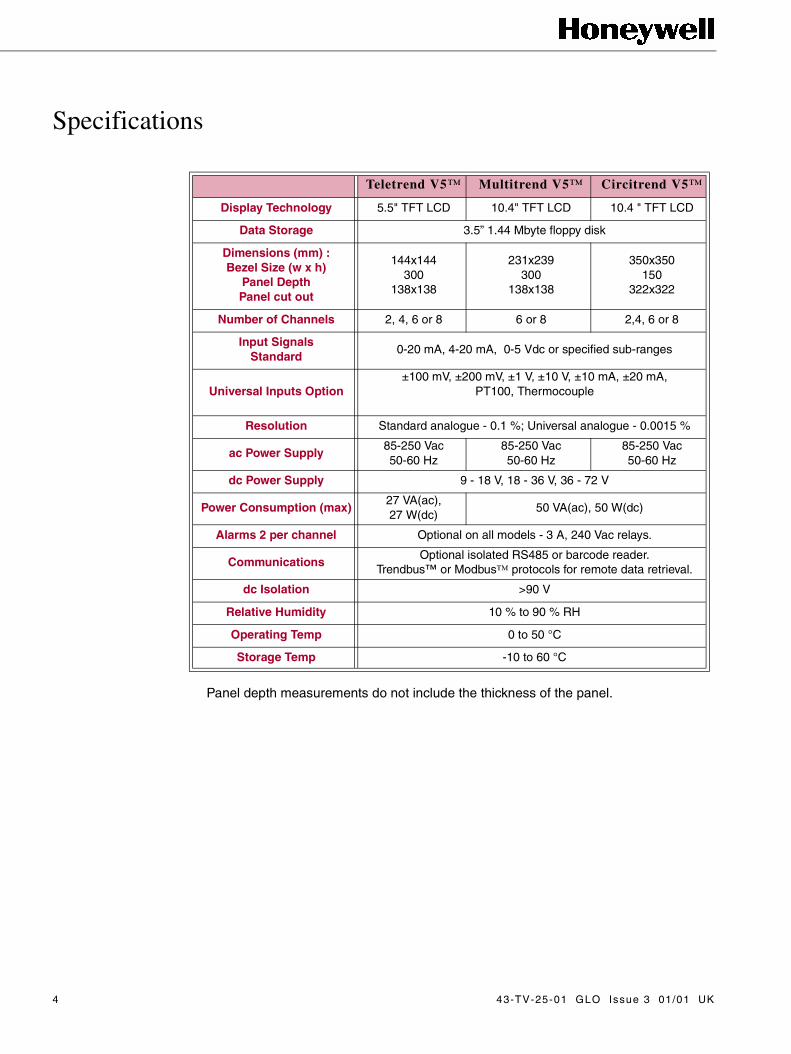
43-TV-25-01 GLO Issue 3 01/01 UKStandard Analogue CardThis example shows a 0-5 Volt device (such as the Honeywell SGS 100 pressure
transducer) connected to channel 1 and a 4-20 mA device (such as the Honeywell SGS 601level transmitter) connected to channel 3. Notice the channel function switch positions -switch 3 is to the left thus selecting channel 3 as a current signal input.
For 24-way connector; torque settings 0,4 N m/3.5 lbf in. Do not over tighten.
Transmitter Power Supply(Optional Extra)
Units fitted with the standard analogue card are equipped with a Transmitter Power Supply.This means that the supply for sensor equipment can be taken from the Honeywell unit. Anexample is shown below.
For 24-way connector; torque settings 0,4 N m/3.5 lbf in. Do not over tighten.
22 23 2421 3 4 5 6 7 8 9 1110 1213 14 15 16 17 18 19 20 21
+ + + + + + + +CH1 CH2 CH3 CH4 CH5 CH6 CH7 CH8
ANALOGUE INPUTS
0 - 5 V Sensor 4 - 20 mA Sensor
Reference
Signal
22 23 2421 3 4 5 6 7 8 9 1110 1213 14 15 16 17 18 19 20 21
+ + + + + + + +CH1 CH2 CH3 CH4 CH5 CH6 CH7 CH8
ANALOGUE INPUTS
0 - 5 V Sensor 4 - 20 mA Sensor
Supply
Supply

Universal Analogue CardThe Universal Analogue Card is used for connecting a wider range of input signals to a
unit, typically thermocouples or resistance thermometers. These are connected as shownin the example below. The thermocouple is connected for internal compensation - detailson how to connect thermocouples using other forms of compensation are given in“Appendix G - Thermocouple Connections” on page 93.
For 24-way connector; torque settings 0,4 N m/3.5 lbf in. Do not over tighten.
Alarm Outputs4 and 8 Relay Alarm Card
The 24-way PCB header on the rear panel labelled Alarm Card connects to 3 A, 240 VacSPCO relays. The pin-outs are labelled NO (normally open), C (common), and NC (normallyclosed). Devices driven by the relays are connected to a 24-way screw terminal plug as forthe analogue inputs. Available alarm outputs start from alarm channel 1 (A1) up to themaximum number of alarms allocated. (NOTE: For a 4-channel Alarm card only Channels 1,2, 3, and 4 are available.) An example of connecting devices to alarm relays is shown below.
Where a device requires a voltage to operate it, such as a 12 Volt buzzer, connect it tothe normally open NO contacts. Other devices may require a low signal to operate them,
22 23 2421 3 4 5 6 7 8 9 1110 1213 14 15 16 17 18 19 20 21
+ + + + + + + +CH1 CH2 CH3 CH4 CH5 CH6 CH7 CH8
ANALOGUE INPUTS
Thermocouple RTD
Signal +ve
Compensation
Signal +ve
Signal -ve Signal -ve
O1 O2 O3 O4 O5 O6 O7 2 O8 1
C C C C C C C CCARDALARM
NC NONC NONC NONC NONC NONC NONC NONC NO
12 Volt
0 Volt Active Low Device12 Volt Buzzer
0 Volt
12 Volt
NB. When installing an Alarm PCB ensure that you alter the hardware settings ofyour recorder in the Factory option of the Special Setups menu as described on page47.
43-TV-25-01 GLO Issue 3 01/01 UK 9

10
43-TV-25-01 GLO Issue 3 01/01 UKand should be connected as shown for Alarm 5. The maximum voltage which may be usedwith the alarm relays is shown in the table in “Specifications” on page 4.
For 24-way connector; torque settings 0,4 N m/3.5 lbf in. Do not over tighten.
8 Input/Output Alarm CardThe 8 Input/Output Alarm Card has 1 A 24 Vdc rated relays connected via a 24-way PCB
header at the rear of the unit.
Each channel can be set up as an input or an output. For output the relay is normally openand closed on alarm.
For 24-way connector; torque settings 0,4 N m/3.5 lbf in. Do not over tighten.
Digital InputsOn a standard 8-channel Alarm card, channels 7 and 8 may be used as digital inputs if
they are not in use as alarm outputs. A digital input is provided by a volt-free contactbetween the normally open NO and common C terminals of an output relay as shown below.
NB. Alarm Relay output 8 corresponds to Digital Input 1, Alarm Relay output 7 to DigitalInput 2, and so on.
For 24-way connector; torque settings 0,4 N m/3.5 lbf in. Do not over tighten.
Serial Interface All serial communications are made via the 9-way D-type plug labelled COMM. on the
rear panel of the unit. Pin-outs for the different types of connections are shown in “AppendixF - Serial Interface Connections” on page 91.
NB. When installing an Alarm PCB ensure that you alter the hardware settingsof your recorder in the Factory option of the Setups menu as described on page47.
Volt-free contact
O1 O2 O3 O4 O5 O6 O7 2 O8 1
C C C C C C C CCARDALARM
NC NONC NONC NONC NONC NONC NONC NONC NO
O1 O2 O3 O4 O5 O6 O7 2 O8 1
C C C C C C C CCARDALARM
NC NONC NONC NONC NONC NONC NONC NONC NO
24 Vdc ONLY
/I3/I4/I5/I6/I7/I8 /I1/I2

Chapter 3: Getting Started
Power UpTo set up a new unit, first check that the power supply connections to the rear
panel are correct.
If the unit is cold allow time for it to warm up to 12 °C or leave standing for 1 hourat room temperature so that any condensation can evaporate before applyingpower.
WARNING
ENSURE SAFETY EARTH CONNECTION
When using an ac supply ensure that a 3-way earthed mains lead is used toconnect the unit.
Failure to comply with these instructions could result in death or seriousinjury.
Switch on the supply to the unit, the display will be illuminated.
The Honeywell V5 logo anda message giving the modeltype of the unit and the status ofthe floppy disk drive will appearbriefly. This is then followed bythe chart display.
If a disk is in the floppy diskdrive during power up, the unitwill automatically load setupsthat have been stored on thedisk. The unit will load the latestsetups from the disk. The unitwill then write those setups todisk under setup file names withthe extension numberincremented by one (see“Writing To Disk” on page 67). If a disk is not in the drive, the unit will load thelatest setups stored in NV RAM. (For more information on NV RAM see “OptionsKey” on page 69.)
Conventional
43-TV-25-01 GLO Issue 3 01/01 UK 11

Basic Keypad Operation
Changing Display ModesChart displays may be seen in two
main modes - conventional or tiled.
• Conventional Mode displays all traces on one chart background.
• Tiled Mode allocates an individ-ual chart background for each trace. Circitrend V5 - also includes Circular mode as one of the basic modes (see “Circitrend
V5 Features” on page 19).
To change between the two screens press the MODE key.
Using Menus To enter the Setup Menus press the MENU key on the front keypad. The Main Menu will
appear on the screen. The selected item on the menu is indicated by the highlight.
• An arrow pointing to the left indicates that you can return to a previous page or display.
• An arrow pointing to the right indicates that you can go into a subsequent menu.
• An item displayed in grey text is not selectable with the unit in its current status.
To move the highlight press the up or down arrow key on thekeypad. For example to move the highlight from Quit to Diskpress the down arrow key twice.
To move back to the previous menu or display press the leftarrow key. If you are unsure about your location within the menuhierarchy press this key continuously until the Main Menu appears.
Pressing the left arrow key while in the Main Menu causes the unit to exit the setupmenus and redraw the chart display.
The MENU key acts as an Enter or Return key. Where an item is marked as having a subse-quent menu, pressing the MENU key with that item highlighted will bring up the next menu.
When an item is not marked as having a subsequent menu, pressing the MENU key willselect or deselect the highlighted item - these items are either functions or tick-selectable.
• A tick-selectable item is marked with a if it is selected.
• A function item is performed as soon as the MENU key is pressed.
Tiled Mode
MENU
SHIFTMODE
12 43-TV-25-01 GLO Issue 3 01/01 UK

Entering TextCertain items in the setup menus when selected
will bring up a prompt in which you are required toenter text. This can be in the form of either a name,number or time and date. The method of enteringtext is generally the same for all prompts. When aprompt appears, the character to be changed will be indicated by a cursor - either aflashing rectangle or a flashing underline. To change the character highlighted by thecursor, press the up or down arrow key. For each key press, the next option from a list ofavailable characters will appear. Holding down a key will allow you to run through the listcontinuously. When you reach the end of a list, release the key and press again to restartthe list.
To delete a character and return to the beginning of a list, highlight the relevantcharacter and press the MODE key.
Others, such as the UNITDESCRIPTION prompt, offer a list ofnumbers, lower and upper caseletters, and some symbols.
NB. If you have altered the contents of a prompt but do not want those changes to takeeffect, escape from the prompt by pressing the SHIFT key - a red cross will appear in thetop left corner of the prompt - then press the MENU key. The list of available characterswill vary according to the prompt. Some prompts, such as the SCALE MAJOR DIVprompt, offer a list of numbers 0-9.
In the TIME/DATE prompt the wholeitem is covered by the cursor ratherthan each individual character. In thisexample, pressing the up arrow keywith the cursor on Mth would changethat item to JAN. Pressing the down arrow key with Year highlighted would change thatitem to 1998. Valid options only are selectable for each item - for instance, only thenumbers 0 to 24 are available for hh. The colour of the text in which the time and date isdisplayed can also be selected by changing the colour of the square at the far right of theTIME/DATE prompt.
To select the item to be changed move the cursor over that item by pressing the rightor left arrow key. When all items have been selected, press the MENU key to enter the textand return to the previous menu.
Software ResetTo reset the unit without removing the power supply, press and hold the Softkey (!), and
the SHIFT and MENU keys at the same time. The unit will respond as if the power supplyto the unit had been disconnected i.e. the internal buffers will be cleared of data and thesetups will return to default settings or load up from disk or NV RAM.
Other keypad operations for normal operation of the unit are described in “ReplayingData” on page 56.
43-TV-25-01 GLO Issue 3 01/01 UK 13

14
43-TV-25-01 GLO Issue 3 01/01 UKCircitrend V5 and Multitrend V5 Text EntryWhen entering text on a Circitrend V5 or Multitrend V5 recorder, it is possible to call up
the entire character map by pressing the Softkey from the text entry prompt. The cursor inthe character map can be manipulated in all directions using the arrow keys on the keypad.Pressing the MENU key causes the highlighted character to be entered in the prompt, thenthe cursor jumps back to the character map ready for the selection of the next character.
To close the character map press the Softkey again. If you want to amend a character inthe text entry prompt, move the cursor to the relevant character in the normal way, then pressthe Softkey to call up the character map again. Select a new character then close thecharacter map as before. Not all characters are available in the character map - a full list ofcharacters is given in “Appendix E - Character List” on page 89.
If you wish to use a character not shown in the character map, you must select it in thenormal way as described in “Entering Text” on page 13. To close the character map pressthe Softkey again. If you want to amend a character in the text entry prompt, move thecursor to the relevant character in the normal way, then press the Softkey to call up thecharacter map again.
If you wish to use a character not shown in the character map, you must select it in thenormal way as described in “Entering Text” on page 13.

Chapter 4: Display Setup Menus
LayoutThe Layout menu is used to select how data is
shown on the screen. (This should not be confusedwith the Pen Setup menu described in “Pen SetupOptions” on page 35 which deals with the way inwhich data is logged.
The options on this menu are:-
• Waterfall Chart () - with this item selected trends will scroll vertically down the display. Waterfall chart also has certain associated options as follows:
• Wide Chart () - the chart area isstretched to occupy the full width ofthe display (i.e. no time and datestamp).
• No Scale () - removes the scalegradients and values from the bar-graph(s).
• Scale on Bar () - draws thescale gradients and valuesover the bargraph indicatorthereby reducing the overallwidth of each bargraph area.(This item cannot be selectedwith the No Scale optionticked.)
• Thin Bar () - reduces thewidth of bargraphs. No gradients or values are displayed along the bar-graph in this mode.
• Time Stamp Rate - select this item to call up the Time stamp sub-menufrom which you can select how frequently you want the time stamp dis-played.
• Trend Name Key - displays the name allocated to each visible trace at the top of the chart display. (Conventional mode only.)
• Black Chart () - turns the background colour of the chart display to black.
43-TV-25-01 GLO Issue 3 01/01 UK 15

• QuickVu Time - calls up the sub-menu opposite.
When the Softkey is pressed with the unit in real-timemode, the trends are shown instantly over a differenttime period selectable from the QuickVu Time menu.For example, if you selected a QuickVu time of 24hours, pressing the Softkey shows the overall trends forthe last 24 hours (see “Softkey Operation” on page59).
• Rotating Bars - displaying several bargraphs means a reduction in chart area available for traces. An alternative solution is to use Rotating Bars, where a single bargraph is displayed at any time and the display switches through all the enabled bargraphs in turn. Selecting this item calls up the Rotating Bars sub-menu - from here you can select the time period each bargraph is displayed before being replaced by the next one, or disable this facility.
• All - select this item to set the same layout for all pens.
• Pens 1-9 (followed by the trace name) - select one or more of these items to set individual pen display parameters (see “Pen Display” on page 23).
In the Layout menu, a tick to the left of a pen indicates that it has been denoted asvisible on the display (unless the text is greyed out, in which case the pen is unavailable).Note that data may still be recorded on a pen even if it is not visible on the display (see“Display Setup Menus” on page 15 on how to enable a pen to log data).
Any changes to the layout will only be noticeable once you Quit the Main menu and thechart is redrawn.
The layout of the display can be changed while the unit is still recording (unlikechanges to the Setups, which require you to stop the recording). However, the layoutchanges made during a recording session will not be saved until a new session is started.
Some of the different formats of display are shown in “Display Formats” on page 17.
16 43-TV-25-01 GLO Issue 3 01/01 UK

43-TV-25-01 GLO Issue 3 01/01 UK 17
Display Formats
Conventional. Pen 1 and 2 - bar trace visible. TrendName key ON.
Conventional 7 pens - bar only. Pens 3 and 7 - inverted bar
Conventional. Waterfall chart ON Tiled. Pen 8 - no bar or trace
Conventional. 4 pens - Black chart ON Tiled. 8 pens - Black chart ON
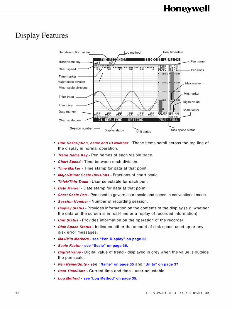
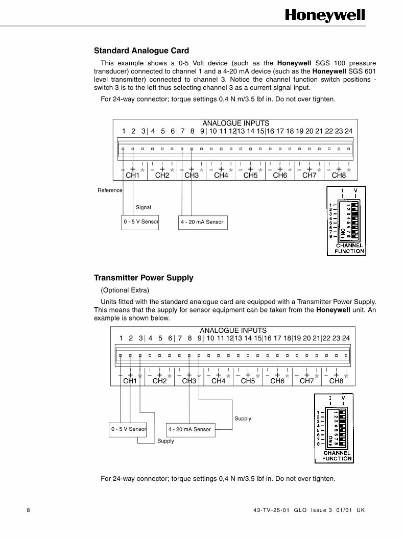
Display Features
• Unit Description, name and ID Number - These items scroll across the top line of the display in normal operation.
• Trend Name Key - Pen names of each visible trace.
• Chart Speed - Time between each division.
• Time Marker - Time stamp for data at that point.
• Major/Minor Scale Divisions - Fractions of chart scale.
• Thick/Thin Trace - User selectable for each pen.
• Date Marker - Date stamp for data at that point.
• Chart Scale Pen - Pen used to govern chart scale and speed in conventional mode.
• Session Number - Number of recording session.
• Display Status - Provides information on the contents of the display (e.g. whether the data on the screen is in real-time or a replay of recorded information).
• Unit Status - Provides information on the operation of the recorder.
• Disk Space Status - Indicates either the amount of disk space used up or any disk error messages.
• Max/Min Markers - see “Pen Display” on page 23.
• Scale Factor - see “Scale” on page 36.
• Digital Value - Digital value of trend - displayed in grey when the value is outside the pen scale.
• Pen Name/Units - see “Name” on page 35 and ”Units” on page 37.
• Real Time/Date - Current time and date - user-adjustable.
• Log Method - see ‘Log Method’ on page 35.
Unit description, name
TrendName key
Chart speed
Time marker
Major scale division
Minor scale divisions
Thick trace
Thin trace
Date marker
Chart scale pen
Session numberDisplay status Unit status Disk space status
Log method Real time/date
Pen name
Pen units
Max.marker
Min.marker
Digital value
Scale factor
18 43-TV-25-01 GLO Issue 3 01/01 UK

Chapter 5: Circitrend V5 Features
Special FeaturesThe additional space afforded by the Circitrend V5 display allows for further
layout options beyond those offered elsewhere in the Honeywell range ofrecorders.
Data may be viewed in three standard modes; Conventional, Tiled (as for otherHoneywell recorders) and Circular (not available on Multitrend V5). WithinCircular mode, there are four main features; Pens, Digitals, Events and Totals.
Different layouts may be produced using these features in various combinations.Each feature, and its effect upon the display layout, is described below:
• Pens - at least one pen must be selected for the circular chart to be drawn.If no pens are selected the chart area of the display is either blank oroccupied by Events (see below). In other modes of display, any number orcombination of available pens may be selected to be drawn on the chartbackground.
• Digitals - a digital read-out is provided for each selected pen and is displayedin tabular form to the right of the circular chart area. If no pens or events areselected the display defaults to the maximum number of available pens.
43-TV-25-01 GLO Issue 3 01/01 UK 19
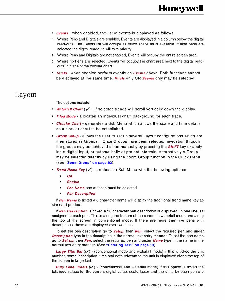
• Events - when enabled, the list of events is displayed as follows:
1. Where Pens and Digitals are enabled, Events are displayed in a column below the digitalread-outs. The Events list will occupy as much space as is available. If nine pens areselected the digital readouts will take priority.
2. Where Pens and Digitals are not enabled, Events will occupy the entire screen area.
3. Where no Pens are selected, Events will occupy the chart area next to the digital read-outs in place of the circular chart.
• Totals - when enabled perform exactly as Events above. Both functions cannot be displayed at the same time, Totals only OR Events only may be selected.
Layout The options include:-
• Waterfall Chart () - if selected trends will scroll vertically down the display.
• Tiled Mode - allocates an individual chart background for each trace.
• Circular Chart - generates a Sub Menu which allows the scale and time details on a circular chart to be established.
• Group Setup - allows the user to set up several Layout configurations which are then stored as Groups. Once Groups have been selected navigation through the groups may be achieved either manually by pressing the SHIFT key or apply-ing a digital input, or automatically at pre-set intervals. Alternatively a Group may be selected directly by using the Zoom Group function in the Quick Menu (see “Zoom Group” on page 62).
• Trend Name Key () - produces a Sub Menu with the following options:
• OK
• Enable
• Pen Name one of these must be selected
• Pen Description
If Pen Name is ticked a 6 character name will display the traditional trend name key asstandard product.
If Pen Description is ticked a 20 character pen description is displayed, in one line, asassigned to each pen. This is along the bottom of the screen in waterfall mode and alongthe top of the screen in conventional mode. If there are more than five pens withdescriptions, these are displayed over two lines.
To set the pen description go to Setup, then Pen, select the required pen and underDescription type in the description in the normal text entry manner. To set the pen namego to Set up, then Pen, select the required pen and under Name type in the name in thenormal text entry manner. (See “Entering Text” on page 13).
Large Title Bar () - (conventional mode and waterfall mode) if this is ticked the unitnumber, name, description, time and date relevant to the unit is displayed along the top ofthe screen in large font.
Duty Label Totals () - (conventional and waterfall mode) if this option is ticked thetotalised values for the current digital value, scale factor and the units for each pen are
20 43-TV-25-01 GLO Issue 3 01/01 UK

displayed (in 12 characters) in a large font. Each pen is allocated one row across thescreen. If this option is not selected for any particular pen the units total is removedfrom the screen rather than be displayed at zero. The totalised values for the pen willalso be displayed in the Duty Label if the Duty Labels Totals option is ticked in the mainLayout Menu.
Black Chart () - changes the background colour of the chart display to black.
QuickVu Time - generates a sub-menu. When the Softkey is pressed with the unit inreal-time mode, the trends are shown instantly over a different time period selectablefrom the QuickVu Time menu. For example, if a QuickVu Time of 24 hours is selected,pressing the Softkey shows the overall trends for the last 24 hours (see “QuickView”on page 59).
Rotating Bars - displaying several bargraphs means a reduction in chart areaavailable for traces. An alternative solution is to use Rotating Bars, where a singlebargraph is displayed at any one time and the display switches through all the enabledbargraphs in turn. Selecting this option produces a Rotating Bars sub-menu, from hereselect the time period each bargraph is displayed before being replaced by the nextone, or disable this facility.
All - select this item to set the same layout for all pens.
Pens 1-9 (followed by the trace name) - select one or more of these items to setindividual parameters (see “Teletrend V5 Pen Display Parameters” on page 23).
In the Layout Menu, a tick to the left of a pen indicates it has been denoted as visibleon the display (unless the text is greyed out, in which case the pen is unavailable). Notethat data may still be recorded on a pen even when not visible on the display. Anychanges to the layout will only be noticeable after selection of Quit from the Main menuand the chart is redrawn.
The layout of the display may be changed while the unit is still recording (unlikechanges made to Setups, which require the user to stop the recording). However, theLayout changes made during a recording session will not be saved until the start of anew session.
To configure a Group select Layout from the Main Menu, then select Group Setup.This generates the Group Setup Menu from which selection of Group Modes areavailable; Conventional, Tiled and/or Circular. For Conventional and Tiled modes,Digitals, Events and Totals are not applicable, thus changing between Groups will havethe effect of changing the number of pens displayed.
Group SetupsHaving specified in which modes the Group feature will operate, select Setup
Groups. The list of Groups (with the current configuration) is displayed, select a Groupto call up the Group Setup menu which offers the following options:-
• Enabled () - tick this item to enable the Group settings. At least one Group must be enabled.
• Group Name - each Group may be given a user-defined name to make identifi-cation easier. Selecting this item results in a GROUP NAME prompt, which may be entered as a five-character text string (see “Entering Text” on page 13).
• Events () - tick this item to display the list of Events for the Group.
43-TV-25-01 GLO Issue 3 01/01 UK 21

• Totals () - tick this item to display the Totals readings for the Group. Totals and Events cannot be selected at the same time. If Totals with Events enabled is selected then Events will automatically be disabled, and vice versa.
• Panel Meter Digitals () - tick this item to display digital readouts for Pens in the Group.
• Pens - select this item to produce a list of Pens from which the user may specify the Pens to be drawn on the circular chart.
• Set As Current () - tick this item to select this Group as the default Group i.e. the Group which will first appear when Exit is chosen from the Setup Menu.
The Group Setups menu also offers a Cycle Groups option from where a sub-menuoffers:
• Auto-Cycle - selecting this item calls up a prompt in which a time interval is entered in minutes. The display will then automatically cycle through the Groups at this interval. If 0 minutes is entered this will disable the Auto-Cycle facility, and Groups must be cycled manually using the SHIFT key or by digital input (see below).
• On Digital - this facility allows the Groups to be cycled by applying a digital input. Selecting this item calls up a list of digital inputs – only one digital input may be enabled to cycle through the Groups. Applying the digital input has the same effect as pressing the SHIFT key and, in the same way that the SHIFT key must be released and then pressed again to cycle through the Groups, the digi-tal input must be removed then re-applied to switch to the next Group (see “Dig-
ital Inputs” on page 10).
Once as many Groups as required are configured and the unit returns to normaldisplay, the name of the current Group will appear at the top of the display (provided thedisplay is in one of the modes that has the Group feature enabled).
Circular ChartsFurther configuration of a circular chart is possible by selecting the Circular Chart
option in the Layout Menu (this item is not available on the Multitrend V5). Thisproduces a sub-menu which offers the following options:
• Scale Details () - this option (if ticked) will show scale details for the first threeavailable pens in addition to the scale details for the chart scale pen (see ChartScale on page 23). A description of this feature may be displayed by selectingScale Details Help.
• Start Time/End Time () - one of these items may be selected to determinewhether the start time or end time of the chart is displayed. The time not selectedwill be displayed in brackets next to the time that is selected on the chart area. Adescription of this feature may be displayed by selecting Start/End Time Help.
22 43-TV-25-01 GLO Issue 3 01/01 UK

Chapter 6: Pen Display
Teletrend V5 Pen Display Parameters• Visible () - enables the pen to be displayed.
• No Bar () - selecting this item will remove the bargraph from the screen.
• Bar () - sets the lowest value of the bargraph display to the bottom of the bar.
• Bar () - sets the lowest value of the bargraph display to the top of the bar.
• No Trace () - removes the trace from the screen.
• Thick Trace () - sets the trace to a thick line for easier visibility.
• Thin Trace () - sets the trace to a thin line for greater accuracy.
• Chart Scale () - selecting this item will cause all pens displayed on the screen in conventional mode to conform to the chart speed and scale of the selected pen. This item cannot be' deselected' - a different pen must be set to Chart Scale instead.
NB. If the Pen selected as the Chart Scale pen is NOT selected as a visible pen,the chart area on the display will be frozen and no traces will be drawn. Ensure thatone of the visible pens is the Chart Scale pen.
• Black Digits () - changes the digital display from the colour of the pen to black. Note that the digits turn grey when the value is outside the pen scale.
• Max Min ON () - the maximum and minimum values of the input signal since the unit was powered up (or since the last reset) are marked on the bargraph display by two white lines. These markers stay in a fixed position until their value is exceeded when they are then pushed to a new maxi-mum or minimum value.
• Max Min Reset (f) - resets the Max/Min markers to the current signal value.
• Compass () - this item displays the scale values as points of a compass. For example, if you set the scale to a bottom value of 0 and a top value of 180, with Major divisions of 45, the bargraph will read N as the bottom value, S as the top value and NE, E, and SE as the Major divisions. The
43-TV-25-01 GLO Issue 3 01/01 UK 23

bottom scale value must be divisible by 45 and if a value other than 45 is selected for the Major divisions, they will be displayed numerically.
• Copy to - copies the display parameters of a pen to other selected pens. For example, to copy the pen dis-play parameters of Pen 1 (TEMP) to Pen 4 and Pen 5, select Copy to from the Pen 1 menu, then select Pens 4 and 5. A tick will appear next to the selected pens.
The Copy to function can only be reversed by goinginto the pen display parameters for the pen that you wishto change. For instance, if you did not want Pen 4 to havethe same parameters as Pen 1 you would have to go backinto the Pen menu (by pressing the left arrow key twice)then select Pen 4 and change the parameters from there.
Circitrend V5 and Multitrend V5 Pen Display Parameters• Visible () - enables the pen to be displayed.
• Add to Group - this is a short-cut to Group Setup (See page
19).
• No Bar () - selecting this item will remove the bar graph from the screen.
• Bar () - sets the lowest value of the bargraph display to the bottom of the bar.
• Bar () - sets the lowest value of the bargraph display to the top of the bar.
• Zero Based Bar () - this option allows the user to set a bar anchored at the position of zero on the bargraph. If the scale is from -100 through 0 to +100 then the bargraph will be drawn from the centre of the bar tile.
• No Trace () - removes the trace from the screen.
• Thick Trace () - sets the trace to a thick line for easier visibility.
• Thin Trace () - sets the trace to a thin line for greater accuracy.
24 43-TV-25-01 GLO Issue 3 01/01 UK

• Duty Label () - (conventional and waterfall modes) an On or Off option per pen which displays the pen name, the current digital value and the units for that pen on an additional large font panel. The information is displayed in the colour of the pen for easy identification at a maximum width of two across the top of the screen. Dependent on the number of pens to which this option is applied the graph area is proportionally reduced. The totalised values for the pen will also be displayed in the Duty Label if the Duty Labels Totals option is ticked in the main Layout Menu.
• Chart Scale () - selecting this item will cause all pens displayed on the screen in conventional mode to conform to the chart speed and scale of the selected pen. This item cannot be' deselected';- a different pen must be set to Chart Scale instead.
NB. If the Pen selected as the Chart Scale pen is NOT selected as a visible pen, thechart area on the display will be frozen and no traces will be drawn. Ensure that one ofthe visible pens is the Chart Scale pen.
• Black Digits () - changes the digital display from the colour of the pen to black. Note that the digits turn grey when the value is outside the pen scale.
• Max Min ON () - the maximum and minimum values of the input signal since the unit was powered up (or since the last reset) are marked on the bargraph dis-play by two white lines. These markers stay in a fixed position until their value is exceeded when they are then pushed to a new maximum or minimum value.
• Max Min Reset (f) - resets the Max/Min markers to the current signal value.
• Compass () - this item displays the scale values as points of a compass. For example, if the scale is set to a bottom value of 0 and a top value of 180, with Major divisions of 45, the bargraph will read N as the bottom value, S as the top value and NE, E, and SE as the Major divisions. The bottom scale value must be divisible by 45 and if a value other than 45 is selected for the Major divisions, these will be displayed numerically.
• Copy to - copies the display parameters of a pen to other selected pens. For example, to copy the pen display parameters of Pen 1 (TEMP) to Pen 4 and Pen 5, select Copy to from the Pen 1 menu, then select Pens 4 and 5. A tick will appear next to the selected pens.
The Copy to function may only be reversed by returning to the pen display parametersfor that particular pen. For instance, if Pen 4 is not required to have the same parametersas Pen 1, return to the Pen menu (by pressing the left arrow key twice) then select Pen 4and change the parameters.
43-TV-25-01 GLO Issue 3 01/01 UK 25

26 43-TV-25-01 GLO Issue 3 01/01 UK

Chapter 7: Unit Setups
DiskThe options in the Disk menu are:-
• Wipe (f) - deletes the contents of the 3.5" disk currently in the disk drive.
• Format HD (f) - formats a high density disk.
• Format DD (f) - formats a double density disk.
• New Recording (f) - star ts the recording of data.
• End Recording (f) - stops the recording of data.
• Clear Error (f) - clears the CAN’T LOG message displayed at the bottom of the screen. This message may be displayed in the event of a fault being detected in the disk or disk drive that is preventing the normal recording of data. (See
“Disk Drives” on page 73) for more information on recording faults.)
• Auto Sensing () - If the unit is in READ ONLY mode (i.e. NOT recording) it detects every 5 seconds whether there is a disk in the disk drive or the disk has been changed. Care should be taken with this option selected as a “replaced” disk may be identified as a “new” disk. Keypad response will be slower with this item selected. (See “Disk Drives” on page 73 for more information on disk error messages.)
Unit SetupThe Setup options are:-
• Unit ID - is used to label each unit with its own ID number and name, as well as a description e.g. a site name.
• Time - allows the user to set the time and date.
• Input - refers to the actual measurement of the input signals. This is sepa-rate from the pen setups (described below).
• Pen Setups - deal with the processing of the measured input signal prior to its presentation to the display. (This is different from the Pen item in the Layout Menu which deals with the actual display of the pens on the screen as described in “Layout” on page 15).
43-TV-25-01 GLO Issue 3 01/01 UK 27

• Totaliser - refers to setting up the Totaliser log interval.
• Special - contains less commonly used setups such as passwords, test pro-grams and sound options.
ADVANCED SETUP OPTION - with the Advanced Setup item ticked in the SpecialSetups menu, a Digitals and a Session Start option will be added to the Setup menu (see“Digitals” on page 51 and “Session Start” on page 53 respectively).
Unit IDSelecting Unit ID will bring up the menu shown here.
All items on this menu bring up prompts when selected.
• Number - A four digit number is required.
It is good practice to ensure that each recorder has a unique ID number, especiallywhen data is being transferred from a recorder to TrendManager Pro. The ID numberalso identifies the recorder when it is being accessed through the Comms port.
ID numbers are therefore not transferred to other recorders with setups that have beenstored on disk. An ID number can, however, be loaded into a recorder from setups savedon disk in TrendManager Pro.
NB. If the unit is reset without a disk in the drive, the ID number will still be saved.
• Name - Any text up to 5 characters in length can be specified.
• Description - Any text up to 19 characters in length can be specified.
TimeSelecting Time on the Setup menu will bring up the TIME/
DATE prompt. The flashing cursor highlights whole items thatare selectable using the up or down arrow key - i.e. the year,month, day, hour (in 24 hour clock format), or minute.
NOTICE
Pressing the MENU will set the displayed time and reset the seconds to zero.If you do not want to reset the clock, press the SHIFT key (a red cross willappear in the top left corner of the prompt) then the MENU key to escape. See“Entering Text” on page 13.
28 43-TV-25-01 GLO Issue 3 01/01 UK

Chapter 8: Input to a Standard Analogue Card
The Input menu deals with the processing of analogueinput signals and their conversion into a digital form which issuitable for later stages of the logging process such as theMaths and Pen blocks (see “Appendix C - SignalProcessing” on page 79).
Selecting Input from the Setup menu generates the inputsoption list. Depending on the model, only the number ofanalogue channels available can be selected starting withInput 1.
The current input selections are shown in green text.
You can either select:
• Show Ranges () - to view the type and range of each input or
• Show Eng Units () - to view the range in engineering units.
(See “Input Block” on page 80 of Appendix Cfor more information on the relationship betweeninput signals and engineering units.)
All channels can be set to the sameconfiguration or channels can be set upindividually. In this example Input 2 is beingselected.
The inputs fall into two basiccategories:1. Volts or
2. Current.
These items are both tick-selectable but also contain sub-menus to allow further setups.
• Square Root Ext () - when selected converts a non-linear input to a linear scale by means of square-root extraction, for example when using pitot flow transducers.
• The Engineering Units item allows you to select those units the input signal represents.
• The Copy to facility allows you to configure more than one input to the same parameters without configuring each input individually.
These items are described in more detail in the following sections.
43-TV-25-01 GLO Issue 3 01/01 UK 29

Volts/CurrentSelect Volts or Current according to the
type of input signal. Both selections call upsub-menus in a similar format - only thevalues and units are different. REMEMBER- a voltage or current input signal must alsobe selected by setting the CHANNELFUNCTION switch on the rear panel to I orV (see “Analogue Inputs” on page 7).
To demonstrate the various methods for setting up an analogue input, a 4-20 mA inputis shown as an example; however, the procedures are the same for all inputs - substitutethe appropriate zero and span values.
Selecting Current from an Input menu calls up therange sub-menu. From here you can select one oftwo standard signal ranges:1. 0-20 mA or
2. 4-20 mA (0-5 V or 1-5 V if you select Volts).
Alternatively you can specify a range within one ofthe standard ranges. To do this select SpecifySubrange to call up the Specify sub-menu.
From here, selecting Zero or Span will call up therelative prompt requiring you to enter the value required.In the example shown, the signal range is selected as 4-16 mA. These values will now be shown in green text nextto the relative menu option in place of the +4.00 mA and +20.00 mA as shown in theSpecify sub-menu.
These values are internally calibrated which means thatthe zero and span values selected are referenced to knownvalues within the unit. Only values up to 5.2 volts or 21 mAcan be entered. If values are entered incorrectly warningmessages appear on the screen as described below.
• Difference between selected zero and span values is less than 1 volt or 4 mA.
• Selected zero and span values are identical.
• A zero or span value outside the full range has been specified, so the range has been adjusted to a standard value.
You will also be provided with an information noticeif you enter a span value that is lower or morenegative than the zero value.
You will also be provided with an information notice if you enter a span value lower thanthe zero value.
The notice also reminds you whether the engineering units currently selected have aspan value greater than the zero value (not reversed) or a span value less than the zerovalue (reversed).
No corrective action is taken with this notice as there are applications where the spanvalue may deliberately be set lower than the zero value.
30 43-TV-25-01 GLO Issue 3 01/01 UK
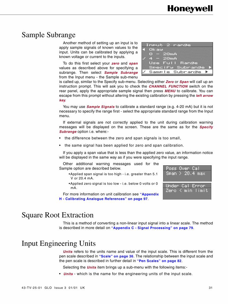
Sample SubrangeAnother method of setting up an input is to
apply sample signals of known values to theinput. Units can be calibrated by applying aknown voltage or current to the inputs.
To do this first select your zero and spanvalues as described above for specifying asubrange. Then select Sample Subrangefrom the Input menu - the Sample sub-menuis called up, similar to the Specify sub-menu. Selecting either Zero or Span will call up aninstruction prompt. This will ask you to check the CHANNEL FUNCTION switch on therear panel, apply the appropriate sample signal then press MENU to calibrate. You canescape from this prompt without altering the existing calibration by pressing the left arrowkey.
You may use Sample Signals to calibrate a standard range (e.g. 4-20 mA) but it is notnecessary to specify the range first - select the appropriate standard range from the Inputmenu.
If external signals are not correctly applied to the unit during calibration warningmessages will be displayed on the screen. These are the same as for the SpecifySubrange option i.e. where:-
• the difference between the zero and span signals is too small,
• the same signal has been applied for zero and span calibration.
If you apply a span value that is less than the applied zero value, an information noticewill be displayed in the same way as if you were specifying the input range.
Other additional warning messages used for theSample option are described below.
•Applied span signal is too high - i.e. greater than 5.1 V or 20.4 mA.
•Applied zero signal is too low - i.e. below 0 volts or 0 mA.
For more information on unit calibration see “AppendixH - Calibrating Analogue References” on page 97.
Square Root ExtractionThis is a method of converting a non-linear input signal into a linear scale. The method
is described in more detail on “Appendix C - Signal Processing” on page 79.
Input Engineering UnitsUnits refers to the units name and value of the input scale. This is different from the
pen scale described in “Scale” on page 36. The relationship between the input scale andthe pen scale is described in further detail in “Pen Scales” on page 82.
Selecting the Units item brings up a sub-menu with the following items:-
• Units - which is the name for the engineering units of the input scale.
43-TV-25-01 GLO Issue 3 01/01 UK 31

• Zero Units - which is the value of the bottom end of the input scale.
• Span Units - which is the value of the top end of the input scale.
Each of these items when selected calls up a prompt in which the relevant text or valuecan be entered (see “Entering Text” on page 13).
Copy to The Copy to facility is the same
for inputs as for pens (see page23). Highlight the input that youwant to configure with the samesetups as the input shown at thetop of the menu box, and pressMENU - a tick will appear next tothe highlighted input.
In this example Inputs 3, 4, and 6 will be configuredin the same way as Input 2.
As with the Pen Setups, to reverse the Copy tofunction you must go into the Input menus for theinput that you wish to change and re-configure thatinput.
In this example if you wanted Input 6 to be differentfrom Input 2, you would have to go back to the Inputsoption list (by pressing the left arrow key twice),select Input 6, and change the configuration fromthere.
32 43-TV-25-01 GLO Issue 3 01/01 UK

Chapter 9: Input to a Universal Analogue Card
A unit fitted with a Universal Analogue Card will automatically adjust the Inputmenus. The procedure for setting up an input is almost the same for Standard andUniversal Analogue cards.
As with standard analogue inputs, the type of input must be determined both inthe Setup menus and on the CHANNEL FUNCTION switch on the rear panel. If youselect a thermocouple or resistance thermometer, the CHANNEL FUNCTIONswitch should be set to V for that input. Details on connecting inputs are given in“Universal Analogue Card” on page 9.
Selecting Volts or Current This will generate respective Volts or Current options menu, which contain
different standard ranges from the Standard Analogue Card menus. Select theappropriate voltage or current range for the inputs to your unit, and, if necessary,specify or sample a sub-range as you would for an input to the Standard AnalogueCard.
ThermocouplesSelect Thermocouple to call up the relevant options menu. This allows you to
select the type of thermocouple and reference junction.
There are four different methods of providing a reference for a thermocouple andthese are listed in the Ref. Junc. sub-menu:-
• Internal Automatic () - uses the temperature reading from the sensor fit-ted to the rear of the recorder.
• External 0°C () - uses a reference junction (effectively a second thermo-couple) held at 0 °C to provide a 0 mV reference.
• Ext Specify () - uses a reference junction held at a constant temperature; this temperature should be entered in the prompt that is called up when you select this item.
• Ext Input () - the temperature of the reference junction is measured by a separate device (such as another thermocouple or RTD). The reading is then fed into a separate analogue input channel which should be specified in the External Input sub-menu.
For more information on thermocouple reference junctions see “Appendix G -Thermocouple Connections” on page 93.
43-TV-25-01 GLO Issue 3 01/01 UK 33

The other options in the Thermocouple menu are:-
• Upscale Burnout () - with this item selected the reading will go to full scale in the event of the thermocouple burning out.
• °C/°F/Kelvin () - selecting one of these items will determine the temperature scale.
• Connection Info - according to the type of thermocouple and reference junction chosen, information on how to connect the thermocouple will be displayed if you select this item.
• Resistance Therm calls up the RT sub-menu. As for a thermocouple, you can chose the temperature scale to which you would prefer to convert the input sig-nal.
• Connection Info option works in the same way as for thermocouples - select this item and details on how to connect an RTD will be displayed. See “Analogue
Inputs” on page 7 for further information on connecting RTDs to a recorder.
NB. that the Units do not need to be specified for thermocouple or resistancethermometer inputs, and that Square Root Extraction is not offered. Units for voltage orcurrent inputs are specified in the same way as for standard analogue inputs.
34 43-TV-25-01 GLO Issue 3 01/01 UK

Chapter 10: Pen Setup Options
The Pen Setup menu is used for setups whichaffect the way data being represented by a pen islogged. Input signals which have been converted intoengineering units are then processed in the mathsand pen blocks (see “Appendix C - SignalProcessing” on page 79).
Pen Setup • Enable () - selects whether a pen is functional.
• Log Enable () - selects whether data displayed by a pen can be written to disk.
• Name - each pen can be allocated a user-defined name (e.g. TEMP1).
• Scale - the top and bottom values of the bargraph dis-play for each pen are selected here, as well as the name of the units for the Pen scale and the divisions for the chart background.
• Maths Expressions - Analogue signals may have a mathematical function performed on them before they are represented as a pen.
• Log Method - generates a sub-menu from which you can select how logged data is presented as a pen.
• Log Speed - various logging rates or chart speeds can be selected for the trace of each pen. Different chart speeds are only relevant in tiled display mode - in conventional mode all traces conform to the chart speed of the pen set to Chart Scale (see “Teletrend V5 Pen
Display Parameters” on page
23).
• Alarm 1/2 - each signal may be allocated two different alarm levels.
43-TV-25-01 GLO Issue 3 01/01 UK 35

• Alarm Log Speed () - the unit can be configured so that in the event of an alarm it switches to a different logging rate. This allows more detailed analysis of data during an alarm condition.
• Totaliser () - produces a sub-menu that allows you to set up the totaliser for each pen.
NameSelecting Name from the individual pen setup
menu brings up the NAME prompt. Type in a namefor the pen as described in “Entering Text” on page13.
Scale NB. When calibrating an input remember to set the Input Engineering units to the same
value as the Pen scale units when the Maths block is not being used. See“Appendix C -Signal Processing” on page 79 on the relationship between Pen Scale and Input setups.
Selection of Scale generates a sub-menu which includes the following options, all ofwhich call up a prompt requiring a value to be entered (see “Entering Text” on page 13):
• Top Value - this allows the user to set the numerical value at the top of the bar-graph display for a pen.
• Bottom Value - this allows the user to set the numerical value at the bottom of the bargraph display.
• Major Div/ Minor Div - the chart background is divided into major divisions (represented by thick grey lines) and minor divisions (repre-sented by thin grey lines). The major divisions are also marked numerically on the bargraph. In this example both bargraphs have been set to a top value of 100, a bottom value of 0, with major divisions of 25 and minor divisions of 5.
If any of these values do not correspond to the rest of the scale, a warning message isdisplayed. These are shown in one of the following formats:-
The value for the Major divisions has been set to a greater value than the span of thescale. If the value for the Minor divisions is greater than the span of the scale a messageMinor Div > Span is displayed.
36 43-TV-25-01 GLO Issue 3 01/01 UK

• The same value for the top scale as for the bottom scale has been selected.
• The value for the Minor divisions has been set to less than 1/60 of the span of the scale.
• The value for the Major divisions has been set to less than 1/10 of the span of the scale.
NB. If the warning messages are ignored, the unitwill automatically correct the condition on leaving theScale menu, and inform the user of the correctiveaction taken, e.g.:-
• A numerical value of 100 has been added to the selected top value, so that the top value is no longer equal to the bottom value.
Other messages include:-
The value for the Minor divisions is now set to 1/60of the total span.
The value of the Major divisions is now set to thesame value as the span of the scale.
These changes are only seen on the display whenthe setups for the pen have been left completely andthe chart is redrawn.
• Units - allows the user to select the name of the units for the scale e.g. volts, amps, °C, inches.
• Scaling Factor - to save having large numbers displayed on the bargraph, a factor by which the values on the scale can be multiplied to give the actual value being represented is shown at the bottom of the bargraph.
The Scale Factor has no effect on the value beingdisplayed - it is only for the user's reference.
Maths ExpressionsMaths expressions can be used to produce a pen that is derived from a mathematical
function performed on one or more input signals.
Maths expressions are only available if enabled by the Option Key - see “Options Key”on page 69.
In this example Pen 1 (P1) isrepresenting the sum of the Input signalsA1 and A2 divided by two (i.e. theaverage of A1 and A2).
43-TV-25-01 GLO Issue 3 01/01 UK 37

Where you want a pen to be a pure representation of an input signal with no mathsexpressions performed, then enter An, where n is the channel number of the input signalto be displayed.
Enter a maths expression in the same way as you would text and as described in“Entering Text” on page 13.
For more information, please see “Appendix D - Maths Expressions” on page 85.
Log MethodInput signals are processed at 250 ms* intervals, and then, having been converted to
engineering units and subjected to maths expressions, the readings are stored until eachtime the data is logged (i.e. written to disk or updated to the display). The intervalbetween data logging is set in the Log Speed sub-menu, and during this time a number ofreadings are stored.
NB. 250 ms for Standard analogue cards, 1 s for 4 channel Universal analogue cards,and 1.5 s for 8 channel Universal analogue cards.
When the data is logged, the list of readings can be dealt with in certain ways, whichcan be selected from the Log Method sub-menu.
• Sample () - logs the last reading taken.
• MaxMin () - logs the highest and the lowest of the stored readings.
• Average () - logs the average of all the readings stored.
• Max () - logs the highest stored reading only.
• Min () - logs the lowest stored reading only.
Log Methods are described in further detail in “Appendix C - Signal Processing” onpage 79.
Log SpeedThe Log Speed can be selected from a range of values
between 5 seconds and 48 hours for every division on thechart. The choice of Log Speed depends on how muchdata needs to be recorded and to what level of accuracy.To monitor a signal that is fluctuating very often a fast logspeed is required to capture the changes - however datastored at this log speed will quickly fill the floppy disk, so if that signal were to bemonitored over a long period of time, and disk space was important, a slower log speedwould be required.
38 43-TV-25-01 GLO Issue 3 01/01 UK
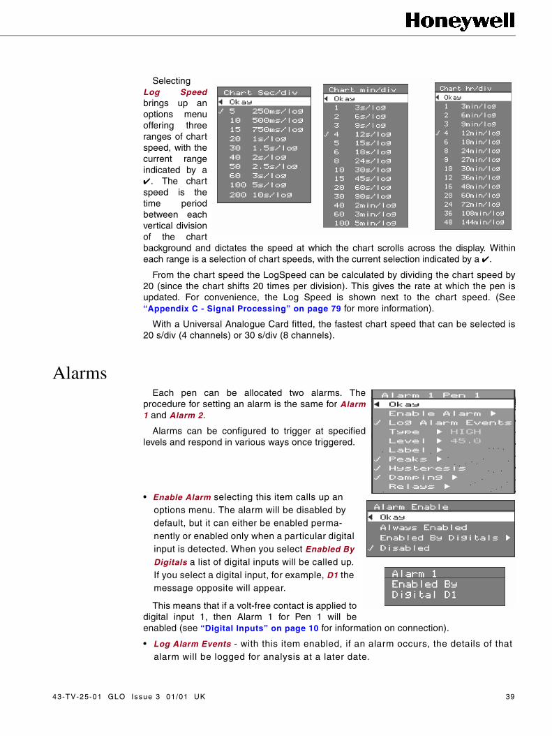
SelectingLog Speedbrings up anoptions menuoffering threeranges of chartspeed, with thecurrent rangeindicated by a. The chartspeed is thetime periodbetween eachvertical divisionof the chartbackground and dictates the speed at which the chart scrolls across the display. Withineach range is a selection of chart speeds, with the current selection indicated by a .
From the chart speed the LogSpeed can be calculated by dividing the chart speed by20 (since the chart shifts 20 times per division). This gives the rate at which the pen isupdated. For convenience, the Log Speed is shown next to the chart speed. (See“Appendix C - Signal Processing” on page 79 for more information).
With a Universal Analogue Card fitted, the fastest chart speed that can be selected is20 s/div (4 channels) or 30 s/div (8 channels).
AlarmsEach pen can be allocated two alarms. The
procedure for setting an alarm is the same for Alarm1 and Alarm 2.
Alarms can be configured to trigger at specifiedlevels and respond in various ways once triggered.
• Enable Alarm selecting this item calls up an options menu. The alarm will be disabled by default, but it can either be enabled perma-nently or enabled only when a particular digital input is detected. When you select Enabled By
Digitals a list of digital inputs will be called up. If you select a digital input, for example, D1 the message opposite will appear.
This means that if a volt-free contact is applied todigital input 1, then Alarm 1 for Pen 1 will beenabled (see “Digital Inputs” on page 10 for information on connection).
• Log Alarm Events - with this item enabled, if an alarm occurs, the details of that alarm will be logged for analysis at a later date.
43-TV-25-01 GLO Issue 3 01/01 UK 39

• Type - four different conditions will trigger an alarm:-
• High - the measured input is higher than the specified alarm level.
• Low - the measured input is lower than the specified alarm level.
• Rate Up - the measured input has increased by more than the specified amount from the previous logged reading.
• Rate Down - the measured input has decreased by more than the specified amount from the previous logged reading.
• Level - select this item to specify the value of the level for the alarm. If the value entered is outside the Pen scale (see “Scale” on page 36) a warning message will appear.
High or Low Alarms
PeaksWith this mode enabled an alarm will only be triggered
when the alarm level has been breached and the loggeddata has reached a peak value. A logged reading isdetermined as being a peak value if it is unchanged from aprevious reading or changes in the opposite direction fromthe changes in the previous readings.
If a logged readingcontinues to change in thesame direction then, whenthe time period specified inthe TIMEOUT prompt haselapsed, the next loggedreading will be considered apeak value. The traces fromthree pens are shownopposite with the points atwhich an alarm would betriggered. Pen 1 and 3 areset for a High alarm at thecorresponding level and Pen2 is set for a Low alarm. Inthe case of Pen 1 the alarmis not triggered until thevalue of the logged readingsstarts to decline. In the case of Pen 2 the alarm is triggered when the value of the loggedreadings levels out.
Logged readings
time
High alarmlevel
Low alarmlevel
Pen 3
Pen 1
Pen 2
3 minutes
Alarm activated atthis point
Alarm activatedat this point
Alarm activated atthis point
High and Low Peak Alarms
40 43-TV-25-01 GLO Issue 3 01/01 UK
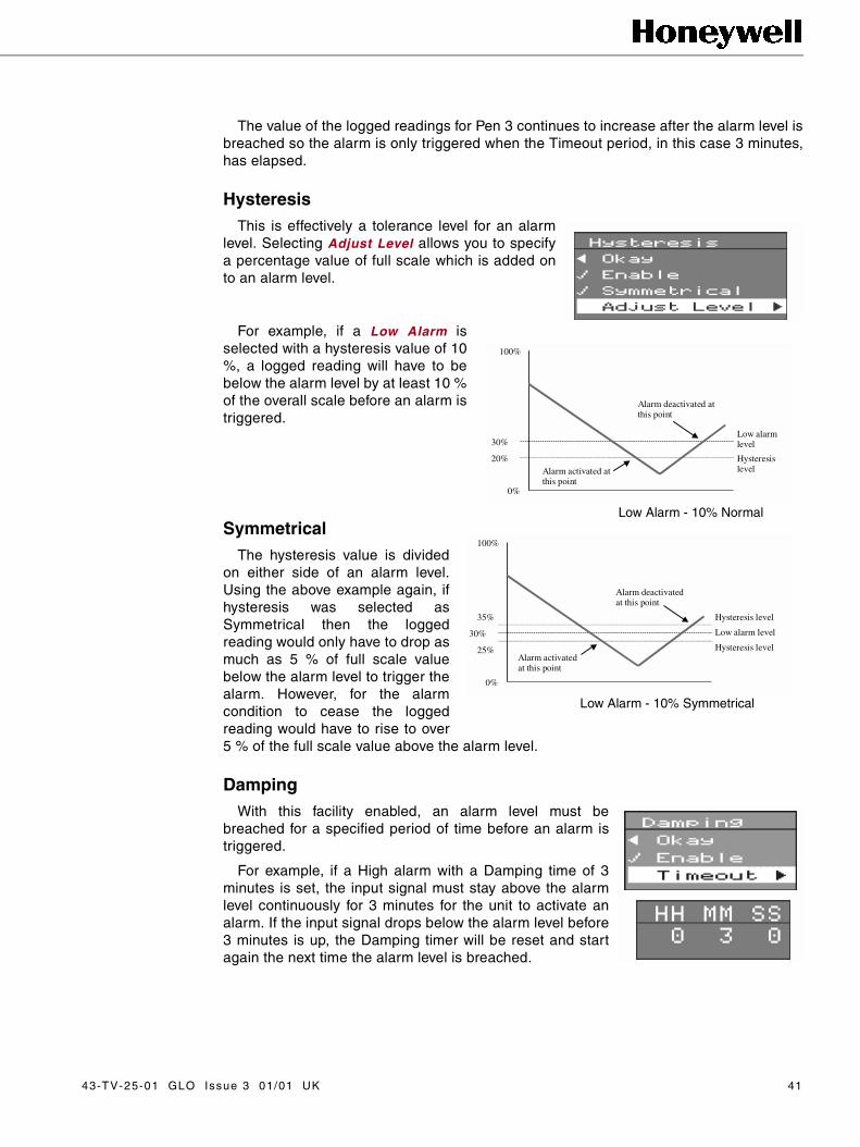
The value of the logged readings for Pen 3 continues to increase after the alarm level isbreached so the alarm is only triggered when the Timeout period, in this case 3 minutes,has elapsed.
Hysteresis This is effectively a tolerance level for an alarm
level. Selecting Adjust Level allows you to specifya percentage value of full scale which is added onto an alarm level.
For example, if a Low Alarm isselected with a hysteresis value of 10%, a logged reading will have to bebelow the alarm level by at least 10 %of the overall scale before an alarm istriggered.
SymmetricalThe hysteresis value is divided
on either side of an alarm level.Using the above example again, ifhysteresis was selected asSymmetrical then the loggedreading would only have to drop asmuch as 5 % of full scale valuebelow the alarm level to trigger thealarm. However, for the alarmcondition to cease the loggedreading would have to rise to over5 % of the full scale value above the alarm level.
Damping With this facility enabled, an alarm level must be
breached for a specified period of time before an alarm istriggered.
For example, if a High alarm with a Damping time of 3minutes is set, the input signal must stay above the alarmlevel continuously for 3 minutes for the unit to activate analarm. If the input signal drops below the alarm level before3 minutes is up, the Damping timer will be reset and startagain the next time the alarm level is breached.
100%
30%
20%
0%
Low alarmlevel
HysteresislevelAlarm activated at
this point
Alarm deactivated atthis point
Low Alarm - 10% Normal
100%
30%
25%
0%
Low alarm level
Hysteresis levelAlarm activatedat this point
Alarm deactivatedat this point
35% Hysteresis level
Low Alarm - 10% Symmetrical
43-TV-25-01 GLO Issue 3 01/01 UK 41

Relays Selecting this item calls up the Relay State menu from which you can select which
relays are to be closed in the event of that alarm being triggered. The relays currentlyselected are identified with a . In this example, if Alarm 1 on Pen 1 was activated,Relays 1, 3 and 4 would close.
NB. For a 4-channel Alarm card only Channels 1, 2, 3, and 4 are available.
Alarm Log SpeedWhen an alarm is activated the unit will
start logging data at the alarm log speedand continue to do so until the alarm isdeactivated. When the unit is no longer inan alarm condition it will return to loggingdata at the normal Log Speed as describedin “Log Speed” on page 38. SelectingAlarm LogSpeed will call up a sub-menu.Select Enable Change () if you want thisfeature to be functional. To select the alarmlog speed, select Adjust Rate and followthe same procedure as for selecting thenormal log speed.
NB. With a Universal Analogue Card fitted the fastestAlarm Log Speed that can be selected is 20 secs/div (4channels) or 30 secs/div (8 channels
42 43-TV-25-01 GLO Issue 3 01/01 UK

Totaliser SetupTotalising is only available when enabled by the Options Key - see “Options Key” on page69.
A totaliser is normally associated withflow-monitoring applications, where theinput to the recorder would be a measureof flow rate (e.g in litres per minute), andyou want to know the total amount that hasflowed over a certain time period (e.g incubic metres). Totalisers are assigned toindividual pens. To set up the totaliser for apen select Totaliser from the Pen Setupmenu. This will generate the totaliser sub-menu which contains the followingoptions:-
• Enable () - select this item if you want a totaliser to be assigned to this pen.
• Log Enable () -select this item if you want the totals for this pen to be logged in the totalisation file.
• Total Units - selecting this item calls up the Total Units prompt which allows you to enter the name of the units for your totaliser values as text (in this case cubic metres).
• Relate Flow Units - select this item to set up the conversion from pen input readings to tot-aliser value. You are required to enter a value in seconds. An example of how you calcu-late this value is given below the prompt. (This value can be calculated automatically using TrendManager Pro - see the on-line Help in TrendManager Pro for details.)
The example says that if your input reading is a constant 1 litres/minute, then 60,000seconds will elapse before 1 cubic metre has flowed, therefore you must enter 6.0 e04 inthe seconds prompt to ensure that your totaliser values are in m3 (the totaliser units).
The current input units and totaliser units are shown in the question above the prompt,in this case the pen is reading in l/m and this needs to be converted to m³.
• Ignore Back Flow () - in some applications when the flow meter is switched off, the totaliser will star t to subtract from the total value (e.g. when a 4-20 mA sig-nal is being applied to an input, switching off the 4-20 mA source will give a reading of 0 mA - if 4 mA corresponds to 0 on the pen scale, 0 mA will give a negative pen reading which will result in a subtraction from the total value). To prevent the totaliser from doing this, select Ignore back flow so that the total value will be held while the flow meter is off.
43-TV-25-01 GLO Issue 3 01/01 UK 43

• Always Standard Form () - with this item selected total values will always be displayed in standard form (e.g. 2.76823e+09) regardless of the length of the number. (e+09 is the same as x 109.)
• Reset on New session () - with this item selected the totals will be reset to zero every time a new recording is star ted.
• Allow Manual Reset/Allow Manual Stop/Go () - these items enable the operations that are selected in the Totals sub-menu (see “View Totals” on page 61.)
In addition to setting up the totaliser for each pen, the Total log interval (which appliesto all pens) must be selected (see the following section) and the totaliser must beoperated (see “View Totals” on page 61.)
Totaliser Log IntervalTotalising is only available when enabled by the Options Key see (“Options Key” on
page 69).
Although totalisers can be assigned to individual pens,they are combined for the purposes of display andrecording into a single totaliser file. Selecting Totaliserfrom the Setup Menu generates the log interval sub-menufrom which you can select the time period between eachupdate of the totaliser.
See “Softkey Operation” on page 59for information onoperating and displaying the totaliser.
MarkersEvent Markers are only available when enabled by the Options Key - see “Options Key” onpage 69.
NB. The Event Marker functions within this recorder are extremely flexible andpowerful. Always ensure that any control actions initiated by the Marker Cause and Effectfacilities are fully tested and verified before using them live in any control application.Markers provide visual and recorded information on the occurrence of certain momentaryevents, as defined by the user.
This section deals with setting up markers. Forinformation on viewing markers and events see “SoftkeyOperation” on page 59. To set up a marker, select Markerfrom the Setup menu, then select the marker that you wantto configure.
Selecting a marker will call up the Marker Setup menuwhich contains the options as described below.
• Enable () - an enabled marker is indicated by a , both in this menu and the list of Markers.
• Tag - selecting this item calls up the Tag prompt which allows you to select a label for the Marker (as described in “Entering Text” on page 13).
44 43-TV-25-01 GLO Issue 3 01/01 UK

• Description - selecting this item calls up the Description prompt which allows you to enter a description of the Marker that will identify it in the Events file.
• Cause(s) - selecting this item calls up the Causes menu as described below.
• Effect(s) - selecting this item calls up the Effects menu as described in the fol-lowing section.
CausesMarkers are set up to be activated by
certain causes or conditions. Theseconditions are selected in the Causesmenu and are as follows:-
• Hotkey () - with this item enabled you can manually set a marker from the Quick Menu as described in “Softkey Operation” on page 59.
• Periodic - selecting this item calls up the Periodic time prompt, in which you can enter the time between markers. This time period is counted from the most recent marker, and the time period counter will restart every time the marker is set by any of the selected causes.
• Weekday(s)/time - this option allows you to specify the exact placement of a marker to the time and day on a weekly basis.
• System State(s) - selecting this item calls up the opposite sub-menu:-
From this sub-menu select a marker to be setaccording to certain conditions of the recorder,namely, if the 'disk full' alarm is activated, theunit has stopped recording or the unit hasstarted recording.
• Total(s) Reset/Stopped/Resumed - the unit can be configured so that a marker will be set in the event of a totaliser being reset, stopped or resumed. (See “Softkey
Operation” on page 59.) Selecting any of these options will call up a sub-menu from which you can select which Pen will cause the marker to be activated. In this exam-ple, only Pen 1 has its totaliser enabled as the other pens are shown in grey text.
• Digital Input(s) - selecting this item calls up a sub-menu from which you can select a digital input that will cause a marker to be set when that input goes high (i.e. when a volt-free contact is made between the NO and C pins as described in “Digital Inputs” on page 10).
• Barcode Reader - selecting this item enables a reading from a barcode reader to set a marker. See “Appendix K - Barcode Reader” on page 101 for more information.
43-TV-25-01 GLO Issue 3 01/01 UK 45

EffectsMarkers can be set up so that, on being
activated, certain operations will be performed.These operations are selected from the Effectsmenu and are as follows:-
• Mark on Chart () - with this item enabled, when a marker is set a vertical line will be drawn on the chart display at the exact time and date of the marker.
• Start/Stop Recording () - a marker can be configured so that when activated it will cause the unit to either stop or star t recording.
• Alarm/Normal LogSpeed () - selecting items will enable a marker to switch the recorder into or out of respectively alarm log speed.
• Total(s) Reset/Stopped/Resumed - these operations, whilst being able to set a marker, can also be activated by a marker. Selections made in the Causes menu should be considered before selecting an option in the Effects menu - for exam-ple, there would be little point in a marker being set by a totaliser reset and then the same marker resetting the totaliser when it is activated.
• Relay Output - a marker can be configured so that when set it also activates cer-tain relay outputs. Selecting this item calls up a sub-menu containing a list of available relays.
• Serial Output - this item is currently not available.
• Counter - selecting this item calls up the Counter sub-menu. From here you can select by how much the Counter is incremented every time the marker is set, and the starting value of the Counter. The Information option tells you how the Counter works and where the Counter readings can be viewed, namely in the Events list (see “Softkey Operation” on page 59).
When the Counter is enabled, the value of the Counter can be incorporated in thedescription of the marker by entering an exclamation mark in the description text. Forexample, if you want the counter value to represent a batch number, enter the text BATCHNO.! in the description field of the marker. The counter value will automatically beinserted in place of the exclamation mark every time that marker is set.
• Another Marker - a marker can be set up to trigger other markers when it is set. Select-ing this item calls up a list of markers which can be set by the source marker. At the end of the list is the Delay first option. Selecting this item calls up a prompt asking you to enter a time. This is the time between the source marker being set and the other mark-ers being subsequently triggered.
In this example Marker M1 will trigger Marker M21 minute and 30 seconds after it is set.
46 43-TV-25-01 GLO Issue 3 01/01 UK
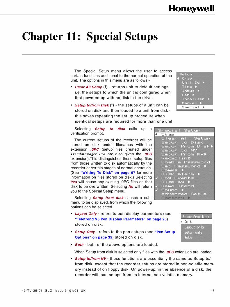
Chapter 11: Special Setups
The Special Setup menu allows the user to accesscertain functions additional to the normal operation of theunit. The options in this menu are as follows:-
• Clear All Setup (f) - returns unit to default settings i.e. the setups to which the unit is configured when first powered up with no disk in the drive.
• Setup to/from Disk (f) - the setups of a unit can be stored on disk and then loaded to a unit from disk - this saves repeating the set up procedure when identical setups are required for more than one unit.
Selecting Setup to disk calls up averification prompt.
The current setups of the recorder will bestored on disk under filenames with theextension .0PC (setup files created underTrendManager Pro are also given the .0PCextension).This distinguishes these setup filesfrom those written to disk automatically by therecorder at certain stages of normal operation.(See “Writing To Disk” on page 67 for moreinformation on files stored on disk.) SelectingYes will cause any existing .0PC files on thatdisk to be overwritten. Selecting No will returnyou to the Special Setup menu.
Selecting Setup from disk causes a sub-menu to be displayed, from which the followingoptions can be selected.
• Layout Only - refers to pen display parameters (see “Teletrend V5 Pen Display Parameters” on page 23) stored on disk.
• Setup Only - refers to the pen setups (see “Pen Setup
Options” on page 35) stored on disk.
• Both - both of the above options are loaded.
When Setup from disk is selected only files with the .0PC extension are loaded.
• Setup to/from NV - these functions are essentially the same as Setup to/from disk, except that the recorder setups are stored in non-volatile mem-ory instead of on floppy disk. On power-up, in the absence of a disk, the recorder will load setups from its internal non-volatile memory.
43-TV-25-01 GLO Issue 3 01/01 UK 47

• Recycling () - with this mode selected the unit will continue to record on a full disk by overwriting the data on that disk, within the recording session currently in progress. (See “Session Numbering” on page 57.)
• Enable Password () - access to Setup menus can be restricted by use of a password. This item is only selectable if a password has been set. Selecting this item causes the RECITE PASSWORD prompt to be dis-played. Respond by pressing the password key com-bination. When you next leave the Setup Menu you will only be able to access it again by entering the password. If you no longer wish to use a password high-light Enable password and press the MENU to remove the next to that item. The unit is no longer password protected.
• Set password - selecting this item brings up the NEW PASSWORD prompt. Respond to this prompt by pressing any combination of four of the eight keys on the keypad. Each time a key is pressed # appears in the prompt. The same key may be pressed more than once in a password. When the fourth key is pressed the RECITE PASSWORD
prompt appears asking you to repeat the key presses you have just used to select the password. This ensures that you have correctly entered and remem-bered the password. If you do not repeat the key presses correctly, the message PASSWORD INCORRECT appears and the password is left unchanged. Press the MENU to return the unit to the Special Setup menu.
• Comms - calls up a sub-menu from which you can select the baud rate required if you are using the recorder in a network configuration. The remainder of the Comms setups are performed in TrendManager Pro on the PC to which the networked recorders are connected.
• Log Events () - tick this item for Events to be recorded (see “List Events” on
page 61 for fur ther information).
• Display - Honeywell recorders are fitted with a screen-saver facility. Selecting this item calls up the BLANK
TIME prompt. The value entered here specifies the num-ber of minutes after which, if there is no intervening key press, the display goes blank. To restore the display press the up arrow key. The display can also be manually switched off by pressing the SHIFT key then the MENU. During the time the display is blank the recorder continues to log data nor-mally. In the event of an alarm, the display will switch on automatically.
• Demo trend () - simulates a sinewave Analogue input on all channels.
NB. The Screen Saver facility is not available on Circitrend V5 or Multitrend V5 orTeletrend V5.
48 43-TV-25-01 GLO Issue 3 01/01 UK

• Sound - selecting this item from the Special Setup Menu calls up a sub-menu which offers the following options for setting a sound which will be emitted whenever a key is pressed outside the Setup menus:-
• Enable () - selects the sound option.
• Longer () - selects the duration of the sound.
• Ring () - selects the sound type.
• Hi Freq () - selects the sound tone.
• Advanced Setup () - tick this item to call up extra options in certain menus. These options are described on page 51 and page 53.
• Factory -
NOTICE
The Factory setups are intended forFACTORY USE ONLY but may beadjusted by the user. Any adjustmentsmade can affect the accuracy of therecorder. Read the following sectionbefore attempting to use factory setups.
• Test Display - provides a series of test screens. Once this item is selected, you must scroll through each screen by press-ing any key until the factory menu is displayed, then exit the Setup menus to return the unit to normal display.
• Serial Number - not accessible for the user.
• Time - performs the same function as the option described in “Time” on page 28.
• Fix No. of Analogs - not accessible for the user.
• Default Analog Refs - resets the reference points of the ADC to factory-specified values. This facility may be used instead of Cal. Analog Refs described below, for instance if you do not have accurate external signals readily available, but the accuracy of these reference points is dependent on how close the signal conditioning characteristics of your recorder are to the average.
• Cal. Analog Refs. - this item is covered in “Appendix H - Calibrating Analogue Ref-
erences” on page 97.
• Recall Factory - resets the unit to factory calibration settings (see “Appendix H -
Calibrating Analogue References” on page 97).
43-TV-25-01 GLO Issue 3 01/01 UK 49

• Clean Drive Head - insert a dry floppy head-cleaning disk, then select this option. Confirmation of cleaning taking place will be displayed including a count down from 30 seconds.
• Hardware options - this item should be selected when any changes have been made to the hardware configuration of the recorder, for instance when installing a Comms or Alarm card. A sub-menu will be called up and the current configuration of the recorder will be shown by the items with a next to them. (In this example, the recorder is not fitted with an Alarm (digital) card or a Comms card.) If you are installing new hardware you must select the corre-sponding item in this menu before that piece of hardware will function correctly.
• Software Info - provides diagnostic codes for factory use, such as checksums for firmware.
50 43-TV-25-01 GLO Issue 3 01/01 UK

Chapter 12: Advanced Setups
DigitalsNB. The Digitals item only appears on the Setup menu if
the Advanced Setups item has been selected in the SpecialSetups menu (see “Special Setups” on page 47).
The standard 8-channel Alarm Card has the facility fordigital inputs on channels 7 and 8 when they are not beingused as relay outputs. A digital input is considered as ONwhen the NO and C pins are connected together (see“Digital Inputs” on page 10).
Digital inputs can be used in maths expressions (see“Appendix D - Maths Expressions” on page 85) and trigger various functionswithin the recorder. These are selectable from the Digital Input menu for eachinput.
The options for digital inputs are:-
• Enabled () - select this item to enable a digital input. NOTE: If a dig-ital input is enabled it will be recogn-ised by the recorder whether or not there is the hardware facility for that input. Only enable digital inputs that are actually being used.
• Log As Event () - with this item selected, any change in the state of the digital input will be logged in the event file.
• Recording Control () - with this item selected, switching a digital input ON will cause the unit to start recording and switching the digital input OFF will stop recording.
• Set Pen Log Rate - this facility allows you to set up a digital input so that when it is switched ON data will star t being logged on any pen at the Alarm Log Rate as described in “Alarm Log Speed” on page 42. In this example, when Digital Input 7 is switched ON, Pens 2, 5 and 6 will all star t being logged at their respective alarm log rates.
When the digital input is switched OFF again,those pens will return to their normal logging rateproviding no alarm condition exists.
43-TV-25-01 GLO Issue 3 01/01 UK 51

• Digital Label - selecting this item calls up the DIGITAL LABEL prompt. A descrip-tion of the digital input in alphanumeric text can be entered here (see “Entering
Text” on page 13).
• On/Off State Labels - selecting either of these items calls up the ON STATE
LABEL or OFF STATE LABEL prompts respectively. A description of the On or Off state of the digital input can be entered here in alphanumeric text (see “Entering
Text” on page 13).
• Relays Out - digitals can be used to activate relay outputs. Selecting this item calls up a sub-menu - from here select Enable to use this facility. To select which Relay outputs are to be activated, select Adjust. This will call up a list of relay outputs - to select (or de-select) a relay, highlight the relay then press the MENU. Selected relays are indi-cated by a . Switching a digital input ON (i.e. closing a contact across the input termi-nals) will activate the selected relays.
52 43-TV-25-01 GLO Issue 3 01/01 UK

Session StartNB. This item only appears in the Setup menu when Advanced Setup has been
selected in the Special Setup menu (see “Special Setups” on page 47).
Selecting this item calls up a sub-menu from which you can select a delaytime for the start of a recording session.Setting a delay time will start therecording on the nearest minute - thisallows for data to be neatly segmentedinto whole minute blocks.
Discard Prior Data is only selectableif there is no time delay selected -otherwise it is automatically enabled. Ifthis function is selected then any datain the temporary storage buffers will bedeleted before a new recording sessionis started.
A countdown is displayed on thescreen when a time delay leading up tothe start of a recording is in operation.To ignore the time delay and startrecording immediately press any key.
Circular ChartThis option is only available on Circitrend V5 recorders.
Selecting this item calls up a menu offering various circular chart time spans. Whenselecting a time span for the circular chart, ensure that the time span is greater than thetime interval for one log of data on the chart scale pen (see “Pen Setup Options” onpage 35). If an incorrect time span is selected the recorder will automatically adjust thetime span to an optimum value.
43-TV-25-01 GLO Issue 3 01/01 UK 53

AboutSelecting About from the Main Menu calls up
the information box shown opposite, whichcontains the model, number of inputs, type ofanalogue input card fitted, serial number andsoftware version of the unit.
Peak stack and Peak Queue provide diagnosticinformation for factory use.
The About box also provides information onwhich of the Options Key facilities are enabled -Maths, Markers and Totals. See “Options Key” onpage 69 for further information.
54 43-TV-25-01 GLO Issue 3 01/01 UK

Chapter 13: Operation
Recording DataTo record the data being displayed on the screen, insert a 3.5" floppy disk, select
Disk from the Main Menu, then select New Recording from the Disk menu (see“Disk” on page 27).
The message WAIT,CHECKING DRIVE appearsfollowed by the status of the diskdrive displayed below in thesame message box. Themessage READ ONLYdisappears from the Unit statussection at the bottom of thedisplay and the current set-ups ofthe unit are written to disk. TheDisk menu is then displayedagain.
The unit is now recording. Theunit will store data in the internalbuffers until they are full then thedata will be written to disk. Themessage WRITING appears inthe Unit status section of thedisplay to indicate that this is happening.
The unit will not start recording if there is a CAN’T LOG message displayed in theUnit status section of the screen (see “Disk Operations” on page 65).
To end the recording go into the Disk menu and select End Recording. The unitwill write the current readings to disk then stop recording - the message READONLY will re-appear in the Unit status section of the display.
If the disk is changed while the unit is in recording mode the message DISKREAD ERROR appears in the Disk space status section of the display. To resumerecording it is necessary to go into the Disk menu and select Clear Error then starta new recording.
CAUTION
CONTROL UNIT DAMAGE
Do NOT eject the disk while a recording is in progress as this may result indamaging the disk drive and the disk itself. To remove a disk, stop the recordingby selecting End Recording from the Disk Menu and wait until the recorder hascompletely finished writing to disk.
Failure to comply with these instructions may result in product damage.
43-TV-25-01 GLO Issue 3 01/01 UK 55

NB. Floppy disks from the following manufacturers are recommended:-
• Verbatim
• Sony
• Maxell
Replaying Data
Keypad OperationData that has been written to disk can be recalled at any time while the unit is recording,
provided that the display is in tiled mode (see “Basic Keypad Operation” on page 12).
To replay recorded data starting from the mostrecent item of logged data of the session inprogress, press the left arrow key. The number ofthis session is displayed in the bottom left corner ofthe display. On pressing the left arrow key themessage REPLAY< appears.
The unit will continue replaying backwardsthrough the session until the beginning of thesession is reached. The black bar moving acrossthe base of the chart background indicates where inthe session the data currently being displayed islocated.
When the beginning of the session is reached the'pause' symbol appears at the bottom of the display. Tocontinue replaying the data through the next previoussession, press the down arrow key.
The session number displayed will decrease by one andthe unit will replay the data in that session until thebeginning of the session is reached. If the 'pause' symbolis still displayed then there is no data to be replayed, sopress the down arrow key to continue to the next session.You can continue replaying data from all the previoussessions in this way.
To review logged data from the beginning of the currentsession, press the right arrow key and the messageREPLAY> appears. The unit will start replaying data fromthe beginning of the session through to either the mostrecent item of logged data (for a session still beingrecorded), or to the end of the session (for data recordedearlier). When the end of the session is reached the 'pause'symbol will appear. To continue replaying data in a subsequent session press the down
MENU
SHIFTMODE
56 43-TV-25-01 GLO Issue 3 01/01 UK

arrow key. If you are replaying the session still being recorded there will be nosubsequent session so pressing the down arrow key will operate the freeze framefunction (see “Freeze Frame (Pause)” on page 63).
During replay mode the direction in which the data is being replayed can be changed atany time by pressing the up arrow key. Each time the up arrow key is pressed themessage in the Display Status section of the screen will alternate between REPLAY< andREPLAY>.
To return to real-time display (i.e. exit replay mode), press the MODE key.
A diagram outlining the replay functions in general is shown below.
Session NumberingData is recorded in sessions. If you start recording with a
new unit and a blank disk, the first recording will be session00. If at any time you change the set-ups of the unit,subsequent data will be recorded in session 01, thensession 02 and so on.
Each time the set-ups are changed, or the recording isstopped then restarted, the session number is incrementedby one. Logged data and Set-ups files stored on disk areidentified by making the session number the filenameextension.
For further information on Session numbering see“Writing To Disk” on page 67.
MENU
SHIFTMODE
Changes direction of replay
Returns unit to real-time mode
Replays forwards from start of session
Replays backwards from end of session
Pause/Go key
43-TV-25-01 GLO Issue 3 01/01 UK 57

58 43-TV-25-01 GLO Issue 3 01/01 UK

Chapter 14: Viewing Data
The Honeywell range has certain features that enable closer analysis of thecontents of the display, while normal operation of the unit continues uninterrupted.
NB. this function is ONLY available whilst the recorder is in Conventional Mode.
Softkey Operation
The Softkey calls up the Quick Menu, which contains options for QuickView,Markers, Events list, Totaliser and Pen Zoom. These features are described infurther detail below.
The QuickView option is selected by pressing the Softkey a second time. Theother options are selected by moving the highlight then pressing the MENU key inthe normal way. However, with the Add Marker option, once you have entered thesub-menus, any press of the left arrow key takes you straight back to the maindisplay NOT the Quick Menu, and, where a marker is selected, it will be setimmediately.
QuickViewThe QuickView facility enables you to look at trends over a different time period
from that dictated by the Chart speed. The QuickVu Time period is selected in theLayout menu described in “Layout” on page 15.
MENU
SHIFTMODE
43-TV-25-01 GLO Issue 3 01/01 UK 59

To operate the QuickView facility, having calledup the Quick Menu, press the Softkey a secondtime. In the example shown opposite, this actionwould change the display from showing trendsmore accurately at 15 seconds per division(Figure 1) to more general patterns over the last10 minutes (i.e. 100 seconds per division - Figure2). As an alternative to this example, if you arelogging data at a Chart speed of 1 hour perdivision, you could set the QuickVu time period to2 minutes - this would allow you to look at anyunusual changes, such as glitches, in closerdetail. This allows you to alternate betweenexamining part of a trend in fine detail or lookingfor general patterns over a longer period of time.
Add MarkerThis function is set up as described in
“Markers” on page 44. From the QuickView menuyou can manually place a marker and edit the Tagand Description of the marker (as described in“Markers” on page 44).
Selecting the Add Marker option will callup a list of markers. Selecting one of thesewill immediately set that marker and returnyou to the main display.
Alternatively you can select the Edit Firstoption. Again this calls up a list of markersfrom which you can select the one you wantto edit.
Having selected a marker you will then bepresented with the Edit sub-menu whichcontains an option to edit the Tag orDescription. There is also an Edit Onlyoption. If this is ticked, any changes youmake to the Tag and Description will beimplemented without setting the marker. Ifthis option is not ticked, as soon as you exitthis sub-menu the marker will be set.
NB. Markers and Totals are only available when enabled by the Options Key - see“Options Key” on page 69 for further information.
Figure 1
Figure 2
60 43-TV-25-01 GLO Issue 3 01/01 UK

List EventsThe Events List contains all recorded
events. Events are certain conditions oroperations which are logged according tothe time and date of occurrence, and cansubsequently be reviewed in a list.
The types of condition or action thatcause Events are summarised below.
• Totaliser - reset, stopped or resumed
• Modes of Operation - e.g. end of recording, change in setups
• Disk - various disk conditions such as disk full, disk changed etc.
• Digital Inputs - change in state
• Relays - change in state
• Markers - when set (if set up to cause an Event)
• Alarms - activated/deactivated
(A full list of Events is given in “Appendix J - Events” on page 99.)
Where the list of Events is longer than one page, you can use the up and down arrowkeys as Page Up or Page Down keys respectively.
View TotalsDetails on how to set up the Totaliser are given in “Totaliser Setup” on page 43 and
“Totaliser Log Interval” on page 44. This section describes how to display and operatethe Totaliser.
Selecting Totals from the Main Menu calls up the Totals menu. The options here are:-
• Okay View - press the MENU key with this item highlighted to display the Total-iser. This consists of a list of all pens that have their totaliser enabled and the corresponding current total value. These totals values will be updated every second. The time period for the log interval is set up as described in “Totaliser
Log Interval” on page 44. To escape from the Totaliser press any key.
• Reset - to reset the totaliser for one of the listed pens, select Reset from the Totals menu, then select the pen that you wish to reset. Selected pens are indi-cated by a .
• Stop Totalling - the totaliser for one of the listed pens can be stopped or paused using this facility. Select Stop totalling from the Totals menu then select the pen that you wish to stop totalling. Selected pens are indicated by a .
NB. The pen you have selected will be reset to 0.00 as soon as the 4 appears in themenu.
43-TV-25-01 GLO Issue 3 01/01 UK 61

When you have selected the pen or pens, press the left arrow key twice and theTotaliser will be displayed. Notice that a pause symbol is now displayed next to the totalvalue of the pen that you have stopped.
• Resume Totalling - to restart a totaliser that has been stopped, select Resume
totalling from the Totals menu then select the pen that you wish to restart. Pens that have been stopped have no next to them.
To pause the Totaliser display, press the down arrow key. The totalisation process willcontinue while the display is paused, so that when you press the down arrow key againthe totals values will be correctly updated.
The maximum number of digits thatcan be displayed is 9. A total cantherefore be in the form of:-
• a 7-digit number to 2 decimalplaces
• an 8-digit number to 1 decimalplace
• a 9-digit whole number
• a standard form number to 5 decimal places (e.g. 2.80759e+09 which is the sameas 2.80759x10⁹)
For a negative number the sign will occupy the first digit.
Zoom PenThis facility allows you to single out a particular Pen for
full-screen display, without interrupting the normaloperation of the recorder either in Real-time or Replaymode.
Selecting Zoom Pen calls up a sub-menu from whichyou can select the Pen which you would like to see on itsown. As soon as you select a Pen the chart area for thatPen is expanded to occupy the full chart background andthe trace for that Pen only is displayed. If a Pen is alreadyticked then you are already in Zoom display for that Pen -you can still select another Pen to be displayed.
To return to the view which you were previously in pressthe MODE key. This facility is ideal for when you arereplaying data and you want a closer look at a particularpen, or when a number of traces are displayed on top ofeach other.
Zoom GroupThis feature is only available as standard on Circitrend V5 recorders, and optionally
on Multitrend V5 recorders.
Selecting the Zoom Group item calls up a list of Groups - stored profiles of variousscreen layouts. When you select one of the available Groups, the display will beconfigured to the settings specified in the Group. See “Group Setups” on page 21 forfurther information.
62 43-TV-25-01 GLO Issue 3 01/01 UK

Freeze Frame (Pause)The contents of the display can be frozen at any time in
replay or real-time mode by pressing the down arrow key.
The pause symbol () will appear at the bottom of thescreen next to the Display status. With the unit in freezeframe mode, screen dumps are still possible and data willcontinue to be recorded. To return to normal viewing pressthe down arrow key again. The pause symbol willdisappear.
Display OffTo preserve the life of the display, in addition to the
screen-saver facility described in “Special Setups” on page 47, it is possible to manuallyswitch off the display by pressing SHIFT and MENU.
The recorder will continue its normal operation while the display is off. To restore thedisplay press the up arrow key.
NB. The Screen Saver facility is NOT available on Circitrend V5 or Multitrend V5.
Screen DumpsThe contents of the display at a particular moment in time can be written to disk in the
form of a bitmap image. This can then be processed on a PC to produce a full-colourreplica of the display on your monitor and a hardcopy printout.
To write a screen dump to disk press the SHIFT key then, at the moment you wish tocapture the display, press the MODE key. Make sure the SHIFT key is on by looking for ayellow rectangle at the bottom left corner of the display.
If the disk in the drive cannot be written to, the message NO SNAPSHOT, DISK OUT OROTHER ERROR appears on the display. Go into the Disk menu from the Main menu andselect Clear error, then try to capture the display again. If the same message appears,check your disk (see “Disk Operations” on page 65).
If the screen dump is successful, the file name that it is stored under will appear on thescreen. (The file name is also displayed on the bitmap image in the Unit status section ofthe display.) Press the MENU key to resume normal operation. See page 67 forinformation on file names for screen dumps.
NB. The screen dump facility is NOT available on Circitrend V5 or Multitrend V5recorders.
43-TV-25-01 GLO Issue 3 01/01 UK 63

64 43-TV-25-01 GLO Issue 3 01/01 UK

Chapter 15: Disk Operations
There are a number of circumstances in which the condition of the 3.5" floppydisk will not allow normal recording of data.
In such circumstances the CAN’T LOG message will be displayed in the Unitstatus section of the screen. Some of these conditions can be rectified by goinginto the Disk menu (see “Disk” on page 27).
Disk FullTwo types of warning message will be displayed in
the event of there being insufficient disk space forfurther recording.
The message DISK FILE LIMIT indicates that themaximum number of files that can be stored on diskhas been reached. For high density disks a maximumof 224 files can be stored, for double density disks amaximum of 112 files can be stored.
The message DISK 100% FULL indicates that thedisk contains the maximum amount of data that can bestored. When these messages are displayed the unitends the recording automatically.
When 90% of the disk space is used up, the Disk space status changes colourfrom green to red. This indicates that disk space is running out and a new recordingon a new disk should be started.
If the disk is to be stored for archiving, start recording on a new disk. If you wishto overwrite the disk with new data, use the Recycling facility described on page47. It is also possible to create space on a disk by only deleting certain files. Forfurther information on disk files see (See “Writing To Disk” on page 67.)
NB. Recycling only overwrites log files. Totaliser or Event files will NOT beoverwritten, and will continue to increase in size, thereby reducing the amount ofdisk space available for recycling (See “Writing To Disk” on page 67.)
43-TV-25-01 GLO Issue 3 01/01 UK 65

Disk UnformattedIf you try to record data onto an unformatted disk a
message will appear on the screen following the WAIT,CHECKING DRIVE message and DISK UNFORMAT'D willappear in the Disk Space Status section of the display.
To format the disk, go into the Disk menu from the Mainmenu. Check whether the disk to be formatted is HighDensity or Double Density and select Format HD or FormatDD accordingly. The FORMAT SURE? prompt appears.
Select YES if you wish to format the disk.
Wiping DisksIf you start recording on a disk that already has some
non required data on it, you may wish to erase the disk.To do this go from the Main menu into the Disk menu andselect Wipe to erase the data on the disk. This will causethe WIPE DISK SURE? prompt to appear. Select YES.
All data will now be erased on this disk and a newrecording can be started.
Disk FaultsWrong Disk
Disk Out
Disk Read ErrorThese messages are displayed in the disk space status section of the screen when a
disk has been removed or changed.
If the unit is in READ ONLY mode (i.e. when it is not recording)it will only detect that the disk has been removed or changed ifAuto Sensing is enabled (see page 27). If Auto Sensing is NOTenabled the unit will only display a DISK OUT or WRONG DISKmessage if it is trying to write to the disk.
The DISK READ ERROR message is displayed when the diskhas been changed and the unit is trying to read from the disk thatwas previously in the disk drive, for example if you change the diskwhile the unit is in record mode.
NOTICE
Formatting a disk will erase all data.
66 43-TV-25-01 GLO Issue 3 01/01 UK

Chapter 16: Writing To Disk
Data is written to disk in five different formats - logged data, setups data, Totalsfiles, screen dumps and events. All data is stored in files on a 3.5" floppy disk whichcan then be accessed by any PC with a 3.5" disk drive.
Logged Data
This is written to disk under a file name in the format shown opposite.
• LOG - specifies that the data stored in that file is logged data.
• 03 - specifies the number of the pen that wrote that data to the screen.
• .005 - is the file extension. This corresponds to the session number of the recording (000 to 099). See “Session Numbering” on page 57 for more information.
Setups Data
When a recording session is started, the current setups of the recorder areautomatically written to disk. The file name is SETUP with the recording sessionnumber as the file extension. In this example the setups for recording session 14are contained in this file. When setups are stored to disk using the Setup to Diskfacility in the Special Setup menu, the file extension becomes .0PC. (Setup filescreated under TrendManager Pro are also given the .0PC extension.) When theSetup from Disk facility is used, the unit will try to load the setups stored in a .0PCfile first. If there is no .0PC file on the disk, the unit will then try to load the latestsetup file it can find. (See “Unit ID” on page 28 on how transferring setup filesaffects Unit ID numbers.)
Screen Dumps
Bitmap images of the display are written to disk under a file name in the formatshown opposite.
• 1234 - is the ID number of the unit from which the bitmap image was taken.
LOG03.005
SETUP.014
SETUP.0PC
1234-05.BMP
43-TV-25-01 GLO Issue 9 01/01 UK 67

• -05 - is the file identifier - the number is allocated by the unit. Numbering starts at 01 and for each screen dump to that disk the number is incremented by one.
• .BMP - specifies that the data stored in the file is a bitmap image. (For informa-tion see “Screen Dumps” on page 63.)
The screen dump facility is NOT available on the Circitrend V5 or Multitrend V5.
Totaliser
Information from the Totaliser is stored in a file with the name TOTAL.nnn. The fileextension corresponds to the number of the recording session in which the totals werelogged.
Event File
The list of logged Events is stored in a single file with a similar format as the Totaliserfile, where the extension refers to the recording session.
TOTAL.008
EVENT.008
68 43-TV-25-01 GLO Issue 9 01/01 UK

Chapter 17: Options Key
Function One
NV RAMThe Options Key is an internal piece of hardware in the recorder that serves two
functions. Firstly, it allows the setups of a recorder to be stored in non-volatilememory (NV RAM), so that in the event of a power failure, the recorder cancontinue operation as soon as power is returned to the unit, whether or not there isa floppy disk in the drive.
Function Two
Maths Expressions
Totalising
Event Markers
Group
Secondly, it enables certain powerful features of the recorder, namely MathsExpressions, Totalising, and Event Markers. It also enables the Group layoutfunction on the Multitrend V5. These features are described in further detail in thefollowing sections:1. “Maths Expressions” on page 37.
2. “Totaliser Setup” on page 43.
3. “Markers” on page 44.
4. “Group Setups” on page 21.
43-TV-25-01 GLO Issue 3 01/01 UK 69

70 43-TV-25-01 GLO Issue 3 01/01 UK

Chapter 18: TrendManager Pro
IntroductionTrendManager Pro is a Windows-based PC package that accompanies the
Honeywell range of recorders as a data acquisition and configuration tool.
FunctionData can be retrieved from recorders to be graphed, printed, archived and
exported to other software packages. Using TrendManager Pro recorders can beconfigured to the setups described in “Display Setup Menus” on page 15.
TrendManager Pro runs under Windows 95™ and offers an easy-to-usegraphical user interface, and all the benefits that Windows™ provides.
A step-by-step guide to using TrendManager Pro is included as an integral partof the package and can be called up using the Help facility.
Data ArchivingAll configurations and settings are stored on the TrendManager Pro database,
as well as all archive and real-time data retrieved from a recorder. System errorsand alarm situations are also logged on the database.
CommunicationsData exchange with a recorder is via the transfer of recorded information or
setups to 3.5" floppy disk, or through RS485 serial communications which allowreal-time down-loading and interrogation of recorders.
43-TV-25-01 GLO Issue 3 01/01 UK 71

72 43-TV-25-01 GLO Issue 3 01/01 UK

Chapter 19: Maintenance
The Honeywell range of recorders contains no parts serviceable by the user. Inthe event of a unit failure contact your nearest Service Department (or anauthorised agent) to arrange for the return of the unit for repair.
CleaningCleaning the unit should be done with a soft lint cloth and warm soapy water.
Solvents and prolonged exposure to detergents can cause damage to the frontpanel. It is recommended that any cloth used for cleaning is damp but NOT wet, toavoid water collecting in the unit.
Disk DrivesDO NOT insert any object, other than a 3.5" floppy disk, or force a disk into the
disk drive. Disks should be removed gently on a parallel plane to the opening of thedisk drive. Avoid tilting the disk up or down during removal as it may damage thedrive.
If the disk is impeded during ejection from the disk drive, it may jam. DO NOT pullthe disk out if there is any resistance. To remove the disk, push it gently back intothe drive and press the eject button again, ensuring the original cause ofimpediment to the disk is removed.
If the disk is still caught in the drive, DO NOT attempt to force it. ContactHoneywell or an authorised agent.
CAUTION
AVOID DISK DAMAGE
To avoid damage to disk drive heads, ensure diskette is removed prior to movingor transporting the recorder.
Failure to comply with these instructions may result in product damage.
Honeywell recommend the following manufacturers of floppy disks:
For optimum disk drive performance it is recommended that the disk driveheads are cleaned every six months. This can be done by inserting a dry floppyhead-cleaning disk and selecting Clean Drive Head from the Factory menu (see“Special Setups” on page 47).
Verbatim Sony Fuji Maxell
43-TV-25-01 GLO Issue 3 01/01 UK 73

The disk drive in your recorder is a highly reliable component that will give many yearsof trouble free operation if the following precautions are observed:
• Use only high quality pre-formatted diskettes as recommended above.
• Never use bulk supply "unbranded" diskettes and "badged" diskettes by a compo-nent wholesale organisation. Experience has shown that "unbranded" and"badged" diskettes, whilst often meeting ISO, ECMA or ANSI standards do notexhibit the longevity, or performance at temperature, available from diskettessourced from reputable manufacturers.
• Every six months (or more often in excessively dusty or harsh environments), usea "dry" cleaning diskette on the recording heads. Suitable "dry" cleaning diskettesare available from Honeywell.
• Never use "wet" cleaning diskettes, these are not recommended by the disk drivemanufacturer, and can cause more harm than good.
• For critical applications, do not continually use the same diskette.
• Do not enable auto sensing if not recording to disk. If left enabled, disk couldbecome damaged.
Operating TemperatureOperating temperatures are described in “Specifications” on page 4. Prolonged
operation at temperatures over 50 °C will cause degradation of the display and may leadto other damage.
If the unit has been moved from a cold environment into a warm one, ensure that theunit has reached a minimum temperature of 12 °C or is left to stand for 1 hour at roomtemperature before applying power, to ensure no condensation remains in the unit.
Front PanelCare should be taken with the front panel when handling the unit. Sharp and hard
objects may pierce the front panel and damage the display. Abrasive materials willdamage the front panel.
KeypadThe keypad is designed for finger operation only. Using a sharp object such as a pen or
finger nail to press the keys will damage the key mechanism permanently.
CalibrationIt is recommended that Recorder calibration is performed at least every year, or in
accordance with industry regulations, to ensure maximum accuracy. See “Appendix H -Calibrating Analogue References” on page 97 for more information.
74 43-TV-25-01 GLO Issue 3 01/01 UK

Appendix A - Quality Approvals
Quality Assurance The Quality Management System of Honeywell has been approved by Lloyd's
Register Quality Assurance Ltd to the following standards:
ISO 9001 : 1994.
Development and maintenance of associated software in accordance with TickIt.
CE MarkHoneywell recorders are compliant with the Low Voltage Directive 72/23/EEC as
amended by 93/68/EEC, and EMC directive 89/336/EEC as amended by 92/31/EEC and 93/68/EEC.
Certificate No. 929041
abcdefg
43-TV-25-01 GLO Issue 3 01/01 UK 75

76 43-TV-25-01 GLO Issue 3 01/01 UK

Appendix B - Transmitter Power Supply
Current Output TransmittersThe transmitter power supply is primarily intended as a simple two-wire
connection facility to any type of 4-20 mA transmitter (24 V nominally powered).
The output voltage from the recorder will be >18 V < 28 V with respect to the -veor +ve terminals of the input channel.
The two-wire connection can also be used to allow further instrumentation to beconnected into the loop. The maximum resistance that may be inserted into theloop will depend on the specification of the transmitter used. Typically this will allowa maximum of 300 Ω into the loop. If further loading is required, you should verifythe maximum resistive load for the transmitter used with the supply at 18 V.
Note:1. The input resistance of the recorder when using a current input is 10 Ω ± 2 Ω and
has negligible effect on the loop loading.
2. The transmitter power supply is internally protected from short circuit conditions.
3. Each of the transmitter power supply channels is isolated from the others but NOTfrom the input terminals of that channel.
Voltage Output TransducersThe transmitter power supply may also be used for 3-wire transducers giving a
voltage output e.g. 1-5 Volts, provided the following is noted:-1. The transmitter power supply voltage will be between 18 and 28 Volts (dependent
on recorder type and tolerances).
2. The transmitter power supply is NOT isolated from the -ve and +ve terminals ofthe channel from which it is derived.
3. The maximum current taken by the transducer is not greater than 25 mA continu-ous under all conditions. The transmitter supplies are short circuit protected butcan give currents higher than 25 mA for short periods (up to 1 Amp peak). Follow-ing a short circuit the transmitter supply will recover within one second, if the faultis removed.
43-TV-25-01 GLO Issue 3 01/01 UK 77

78 43-TV-25-01 GLO Issue 3 01/01 UK

Appendix C - Signal Processing
Analogue input signals are processed by being passed through various 'blocks'or stages which convert the electrical input signal to a value displayed on screenand logged to disk.
Stages of signal processingSignal applied
to inputterminals
INPUT BLOCK
Analog-to-Digitalconversion
Input signal inengineering units
MATHS EXPRESSION
Signal processed by maths equationand result passed to pen
every 250 ms
DATA LIST
Pen readings processed everylog interval according to log
method
TOTALISER
Pen readings totalledevery total log interval
Pen value logged todisplay/disk file everylog interval
Pen totals logged toTotaliserdisplay/disk file
43-TV-25-01 GLO Issue 3 01/01 UK 79

Input BlockInput signals are converted to a digital
value by the A-to-D converter (ADC).Within the Input block this digital value issubjected to a mathematical function inorder to present the signal as a ratio ofthe total span. E.g. if a 12 mA signal isapplied within a 4 - 20 mA range, theratio will be (12 - 4) / (20 - 4) = 0.5.
This ratio is then converted toengineering units as specified in theInputs setup menus (see “Input to aStandard Analogue Card” on page 29).The zero and span engineering units (forexample 0 and 100) create a scale onwhich the value of the input signal will lie.Using the same example, the ratio of 0.5 would be converted to 0.5 * (100 - 0) + 0 = 50.
The same method is used for anon-linear signal except thatwhen square root extraction isselected from the Input menu thesquare root of the ratiocalculation is taken as being theratio value.
Maths ExpressionsThe numerical value of the input
signal (in engineering units) is now fedinto a maths expression. This can be assimple as P1 = A1 (which will result inthe signal from Analogue Input 1 beingpassed to Pen 1) or a more complicated combination of maths functions and readingsfrom more than one input.
The result of the maths expression is passed to a pen via the data list. Mathsexpressions are selectable by the user and are described in greater detail in “Appendix D- Maths Expressions” on page 85.
( )SIGNAL – ZERO SIGNAL
SPAN SIGNAL – ZERO SIGNAL
from ADC
RATIO (value between 0 and 1)
RATIO x (SPAN UNITS – ZEROUNITS) + ZERO UNITS
UNITSto maths expression
(e.g. 0-100%)
Normal input block
SIGNAL IN
SIGNAL IN Non-linear
SIGNAL – ZERO SIGNAL
SPAN SIGNAL – ZERO SIGNAL √( )
RATIO (value between 0 and 1)
RATIO x (SPAN UNITS – ZEROUNITS) + ZERO UNITS
UNITSto maths expression
(e.g. 0-100%)
Linearized input block
80 43-TV-25-01 GLO Issue 3 01/01 UK

Data ListThe results of maths expressions are fed into a data list every 250 milliseconds. This is
a temporary store where the readings are kept until each log interval.
At each log interval the readingsin the data list are processedaccording to the log method andthe result (or results) are thenpassed to the appropriate pen(see “Log Speed” on page 38).
The different log methods aredescribed below.
• If Sample is selected, the last reading from the Data List will be logged.
• If MaxMin is selected, two readings will be logged - the maximum and minimum read-ings held in the Data List - and a trace drawn between the two. Note that if the logging interval is 250 ms (i.e. the Log Speed is 5 secs/div) there would only be one reading in the list so to save disk space the Sample method would be more suitable.
• Alternatively, selecting Max will cause the maximum reading only to be logged and selecting Min will cause only the minimum reading to be logged.
• If Average is selected, the average of all the readings in the Data List will be logged.
TotaliserThe totaliser can be selected
as an optional extra alongside thenormal processing of an input.The totaliser takes the results ofa maths expression and placesthem its own Data List in a similarway as a Pen except that it addseach reading to the previousreading in the list.
On each total log interval, thelast reading in the list is taken asthe logged reading. (See“Totaliser Log Interval” on page44.)
Value todisk/display atlogging intervals
(depending on LogMethod)
Signal In
InputEngineeringUnits
MathsExpression
DATA LIST
Reading addedevery 250 ms
Maths results
Signal In
InputEngineeringUnits
MathsExpression
DATA LIST
next readingadded to previousreading in listthen result placedin list
Maths resultsreading addedevery second
Last value in list toTotaliser display/diskfile at ‘total log’intervals
43-TV-25-01 GLO Issue 3 01/01 UK 81

Calibrating Analogue ReferencesBefore any of the above processing of an input signal takes place, the 'raw' analogue
input must be converted to a digital signal.
To calculate the analogue input signal that corresponds to a given digital value it isnecessary to use reference points. These are two digital values whose correspondinganalogue input values are known (normally at either end of the signal range).
If these references are placed on agraph and a line drawn between the two,then for any digital value a correspondinganalogue value can be read.
In the example shown opposite, readingsfrom the ADC of 100 and 50 are givenreference values of 5 and 0 voltsrespectively. From this information, if avalue of 60 is read from the ADC then it iscalculated that an input signal of 1 volt isbeing applied.
These reference points can either bespecified (i.e. the recorder is 'told' that fora particular reading from the ADC thecorresponding value is 5 volts and foranother reading the value is 0 volts) or theycan be sampled (i.e. set up from known external signals). The latter method is used toCalibrate Analogue References as described in “Appendix H - Calibrating AnalogueReferences” on page 97.
As an example, if you were calibrating reference points for a 0-5 volt input, you apply aknown 0 volt signal and instruct the recorder to use the reading from the ADC as areference point for 0 volts, then repeat the procedure for a known 5 volt signal. Obviously,the accuracy of this method is highly dependent on the accuracy of the known signalsbeing applied.
The Default Analogue Refs in the Factory menu (see page 49) will specify thereference points to values that are in-line with the average characteristics of the ADC. Formost applications the accuracy of this method is sufficient, but should the characteristicsof a particular ADC stray from the average then calibration to external signals will providefar greater accuracy.
For optimum accuracy all recorders are calibrated to external signals in the factorybefore being shipped. The Factory Recall option in the Factory menu will reset the unit tothese calibration settings in the event of any drift in the A-to-D conversion of input signals.
Pen ScalesWithin the Pen block certain mathematical functions can be performed on the signal.
These mathematical expressions of the signal must be considered when setting the Penscale, as described in “Scale” on page 36.
Setting the Pen scale dictates how the input signal is seen on the display. For example,if the Input scale is set at 0 to 100 in engineering units and the Pen scale at -50 to 150units, the effect will be that of 'zooming out' from the signal i.e. the signal will appear
050
5
Input signal (volts)
100
Digital value from ADC
82 43-TV-25-01 GLO Issue 3 01/01 UK

smaller. Alternatively, if a Pen scale of 25 to 75 is selected the effect will be 'zooming in'on the signal, and only a section of the signal will be seen.
The examples opposite show how asinusoidal signal fluctuating over thefull input range would appear fordifferent pen scales. Where the inputsignal exceeds the range of the penscale, the trace is displayed at fullscale and the digital values aredisplayed in grey text.
For steadier signals the visible effectwill be different. For example aconstant input signal with a value of 80units on the input scale would merelyshift its position on the displayaccording to the Pen scale settings. Inthis example, where the pen scale is25 to 75, an input signal of 80 unitswould be displayed as full scale, as itsvalue exceeds the range of the Penscale. This only occurs on the display -the recorded value on disk would stillbe 80 units.
The relationship between Input andPen scales should be considered whendealing with Maths Expressions. (Formore information see “Maths Expressions” on page 37 and “Appendix D - MathsExpressions” on page 85). Some examples are shown below.
Example 1. A Maths Expression is enteredas follows:- P1 = log(A1)
This means that the signal displayed as Pen1 will be the logarithmic value of the signalapplied to Input 1. The scales should be set upaccordingly. If the Input scale is 0 to 100 unitsthen, for the full signal range and maximumresolution, the Pen scale should be set atlog(0) to log(100), which is 0 to 2.
Example 2. A Maths Expression is enteredas follows:- P2 = A1 + A2
This means that the signal displayed as Pen2 will be the sum of the values of the signalsapplied to Input 1 and Input 2, i.e. 0 + 0 to 100+ 100, which is 0 to 200.
INPUT SIGNAL
100
0
Input Eng. Units
PEN SIGNAL
Pen Scale
150
-50
INPUT SIGNAL
100
0
Input Eng. Units
75
25
PEN SIGNAL
Pen Scale
INPUT SIGNAL
100
0
Input Eng. Units
75
25
PEN SIGNAL
Pen Scale
80
80
Input Eng. Units
100
0
P1 = log(A1)
Pen Scale
2
0
Input Eng. Units
100
0
P1 = A1 + A2
Pen Scale
200
0
Example 1
Example 2
43-TV-25-01 GLO Issue 3 01/01 UK 83

84 43-TV-25-01 GLO Issue 3 01/01 UK

Appendix D - Maths Expressions
A maths expression is made up of a number of terms. A term is the smallest validcomponent in a maths expression and can be a variable, operator or function.Certain operators and functions have the same effect in a maths expression - forexample, $ or SQRT will both perform the square root of an operand.
An operand may be a constant (i.e. a fixed number) or a variable. The variablesthat can be used are described below.
• An - The letter A followed by a number causes the reading taken from an analogue input (denoted by the number) to be inserted in the maths expression. In this example, the readings from Analogue Input 1 are being displayed on Pen 1.
• In - The letter I followed by a number causes the reading taken from a digital input (denoted by the number) to be inserted in the maths expression. In this example, the result of digital input 1 multiplied by digital input 2 is displayed on Pen 9. As digital inputs are read as either 1 or 0, the result of this maths expression will effectively be an AND function (i.e. digital inputs 1 and 2 must both be 1 for the value dis-played on Pen 9 to be 1 - see “Boolean Expressions” on page 88).
• On - The letter O followed by a number causes the state of a Relay output (denoted by the number) to be inserted in the maths expression. A Relay output is read as 1 when active and 0 when inactive.
• Operators - can be either unary or binary. A unary operator requires one operand after it to make a valid expression, whereas a binary operator requires an operand on either side. For example # is a unary operator, as in #2 (2 squared), whereas * is a binary operator, as in 2*3 (2 multiplied by 3).
The available functions and operators for maths expressions are describedbelow. Where a function and operator have the same effect they are listed together.A U after the operator denotes a unary operator and a B denotes a binary operator.
43-TV-25-01 GLO Issue 3 01/01 UK 85

.
EXPRESSION EXAMPLE DISPLAY
Add Operator + (B) Analogue Input 1 added to Analogue Input 4 displayed on Pen 1
Subtract. Operator - (B) Analogue Input 1 subtracted from Analogue 2 displayed on Pen 1
Negate. Operator - (U)The sign of the value Analogue
Input 1is reversed. A reading of 6 would be displayed as -6 and vice
versa
Multiply. Operator * (B) The value of Analogue Input 2 multiplied by two
Divide. Operator: / (B) Analogue Input 1 divided by Analogue Input 3
Square Root. Function: SQRT Operator: $ (U)
Pen 1 displaying the square root of Input 3 added to Input 4
Square. Function SQ Operator: # (U)
The value of Input 3 squared and displayed on Pen 1
Round. Function ROUND
The value of Analogue Input 2 divided by four and rounded to the
nearest whole number
Reciprocal. Operator ! (U)
The reciprocal of the value of Analogue Input 2 is displayed on
Pen 1. (An alternative way of writing this expression would be 1 / A2).
86 43-TV-25-01 GLO Issue 3 01/01 UK

* See “Appendix C - Signal Processing” on page 79 for further information onsampling.
Absolute. Function ABS Operator: & (U)
The result of Input 4 subtracted from Input 1 is always considered as
positive. If A1 = 2, and A4 = 3.5, the value displayed on Pen 1 would be
1.5 not -1.5.
Logarithm to base 10. Function: LOG
Operator: @ (U)
Logarithmic value (LOG10) of Input 1 displayed on Pen 1.
Natural logarithm. Function: LN
Natural logarithmic value (loge) of Input 2 displayed on Pen 1.
Low value. Function: LO Pen 1 displays whichever is the
lowest value out of Input 1 and Input 3. Note the inputs being compared
are separated by a comma.
High value. Function: HI Pen 1 displays the highest value out of Input 1 and Input 3.
Root. Operator: ~ (B) The third root value of Input 1 displayed on Pen 1.
Power. Operator: ^ (B) The value of Input 2 to the power of 3 (or cubed) displayed on Pen 1.
Modulus. Operator: % (B)
The value of Input 2 is divided by 20 and the remainder ONLY is
displayed on Pen 2. Therefore the signal will be within 0-19.
Rolling Average. Function: R
* A maximum value of 40 can be entered for this function.The value displayed on Pen 1 is the average
value of the last eight samples taken from Input 2 (each sample being
taken every 250ms.)
EXPRESSION EXAMPLE DISPLAY
43-TV-25-01 GLO Issue 3 01/01 UK 87
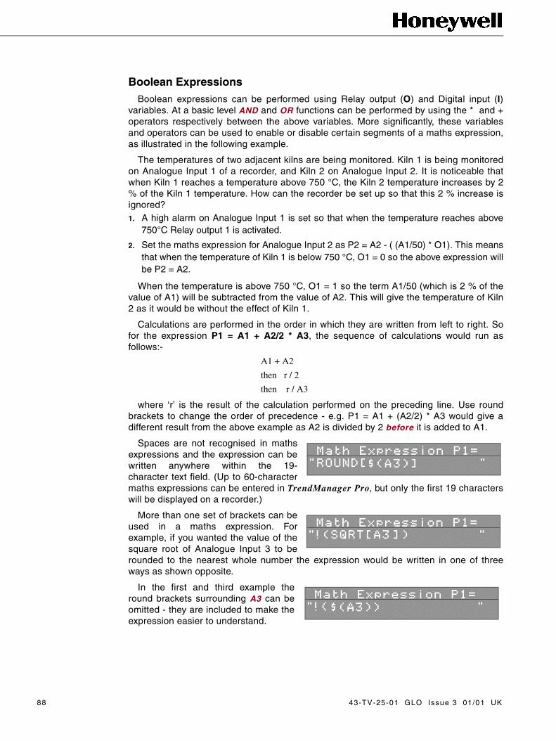
Boolean ExpressionsBoolean expressions can be performed using Relay output (O) and Digital input (I)
variables. At a basic level AND and OR functions can be performed by using the * and +operators respectively between the above variables. More significantly, these variablesand operators can be used to enable or disable certain segments of a maths expression,as illustrated in the following example.
The temperatures of two adjacent kilns are being monitored. Kiln 1 is being monitoredon Analogue Input 1 of a recorder, and Kiln 2 on Analogue Input 2. It is noticeable thatwhen Kiln 1 reaches a temperature above 750 °C, the Kiln 2 temperature increases by 2% of the Kiln 1 temperature. How can the recorder be set up so that this 2 % increase isignored?1. A high alarm on Analogue Input 1 is set so that when the temperature reaches above
750°C Relay output 1 is activated.
2. Set the maths expression for Analogue Input 2 as P2 = A2 - ( (A1/50) * O1). This meansthat when the temperature of Kiln 1 is below 750 °C, O1 = 0 so the above expression willbe P2 = A2.
When the temperature is above 750 °C, O1 = 1 so the term A1/50 (which is 2 % of thevalue of A1) will be subtracted from the value of A2. This will give the temperature of Kiln2 as it would be without the effect of Kiln 1.
Calculations are performed in the order in which they are written from left to right. Sofor the expression P1 = A1 + A2/2 * A3, the sequence of calculations would run asfollows:-
A1 + A2
then r / 2
then r / A3
where ‘r’ is the result of the calculation performed on the preceding line. Use roundbrackets to change the order of precedence - e.g. P1 = A1 + (A2/2) * A3 would give adifferent result from the above example as A2 is divided by 2 before it is added to A1.
Spaces are not recognised in mathsexpressions and the expression can bewritten anywhere within the 19-character text field. (Up to 60-charactermaths expressions can be entered in TrendManager Pro, but only the first 19 characterswill be displayed on a recorder.)
More than one set of brackets can beused in a maths expression. Forexample, if you wanted the value of thesquare root of Analogue Input 3 to berounded to the nearest whole number the expression would be written in one of threeways as shown opposite.
In the first and third example theround brackets surrounding A3 can beomitted - they are included to make theexpression easier to understand.
88 43-TV-25-01 GLO Issue 3 01/01 UK

Appendix E - Character List
The following characters will NOT appear on the display in Conventional Mode.
The characters contained in cells with a dotted border are only available for text.
The characters contained in shaded cells are only available for mathsexpressions.
+ ! “ # Ñ $ % & ‘ ( )_` * + , - .
/ 0 1 2 3 4 5 6 7 8 9 ; : < = > ?
° @ A B C D E F G H I J K L M N O
P Q R S T U V W X Y Z [ \ ] _ ^ ±
_ ` a b c d e f g h i j k l m n o
p q r s t u v w x y z < cc | >
/ ~ 10 0 -1 -2 -3 -4 -5 -6 -7 -8 -9 1
2 3 4 5 6 7 8 9 © !!!! """" ……… #### $$$$
43-TV-25-01 GLO Issue 3 01/01 UK 89

90 43-TV-25-01 GLO Issue 3 01/01 UK

Appendix F - Serial Interface Connections
RS485 Trendbus™ network Pin-outs for RS485 Trendbus™ serial connections are as follows:-
RS485 Modbus™ networkPin-outs for RS485 Modbus™ serial connections are as follows:-
NB. The type of serial communications for each unit is factory selected accordingto customer specifications. Should you wish to change your serial commsconfiguration, please contact your nearest service centre.
0 Volts (isolated)
RX/TX +ve
RX/TX -ve
NotConnected
NotConnected
1
2
3
4
5
6
7
8
9
0 Volts (isolated)
RX/TX -ve RX/TX +ve
Not Connected
Not Connected
Not Connected
1
2
3
4
5
6
7
8
9
Not Connected
Not Connected
Not Connected
43-TV-25-01 GLO Issue 3 01/01 UK 91

92 43-TV-25-01 GLO Issue 3 01/01 UK

Appendix G - Thermocouple Connections
The different methods for connecting thermocouples according to the type ofreference are shown below.
Internal Reference
Internal Reference the reference junction is where the thermocouple isconnected to the input terminals of the recorder, and the temperature at thisjunction is being measured by a temperature sensor on the rear panel of therecorder. The reading from this sensor is read off against a value taken from thethermocouple table, which corresponds to the type of thermocouple being used.(To specify the type of thermocouple, see “Input to a Universal Analogue Card”on page 33.) The corresponding reading in volts for the temperature measured bythe sensor is then used as a reference for the reading from the thermocouple.
Input terminals onrear panel ofrecorder
Polynomial(converts
voltage readingto temperature)
Inputsadded(C + D)
Temperaturereading to
mathsexpression
Inputs multiplied(A * B)
Thermocoupletable
Value in V/ºCaccording to typeof thermocouple
D
A
C
B
(Volts)
Reading in volts
Measuringjunction
Temperaturesensor on rearpanel ofrecorder
Readingin ºC
43-TV-25-01 GLO Issue 3 01/01 UK 93

External Reference @ 0 °C
External Reference @ 0 °C by keeping the reference junction at 0 °C the negative inputis acting as a 0 Volt reference so the voltage reading from the thermocouple can be passeddirectly to the polynomial where the corresponding temperature reading can be found.
External Reference @ Specified Temperature
External Reference @ specified temperature if the reference junction can be kept at aconstant known temperature other than 0 °C this temperature can be specified in thesetup menus as described in “Input to a Universal Analogue Card” on page 33. Thisreference temperature is then used in the same way as the reading from the temperaturesensor using the Internal Reference method.
Polynomial(converts voltage
reading totemperature)
Temperature reading tomaths expression
(Volts)V
Reference junctionheld at 0ºC
Measuringjunction
0 Volts
Input terminals onrear panel ofrecorder
Reference Junctionheld at 0 °C
Polynomial(converts
voltage readingto temperature)
Inputsadded(C + D)
Temperaturereading to
mathsexpression
Inputs multiplied(A * B)
Thermocoupletable
Value in V/ºCaccording to typeof thermocouple
D
A
C
B
(Volts)
Reading in Volts
Reference junctionheld at constant knowntemperature
Measuringjunction
Input terminalson rear panel ofrecorder
Temperatureof Referencejunctionspecified insetup menus
94 43-TV-25-01 GLO Issue 3 01/01 UK

External Input Reference
External Input Reference the reference temperature reading in this method is providedby a separate temperature measuring device connected to another input. This input isprocessed in the normal way and then passed back into the thermocouple signalprocessing system as a temperature reading.
Temperature measuring deviceconnected to separate input
Referencejunction
Measuringjunction
Input terminals onrear panel ofrecorder
Thermocoupletable
Normalsignal
processing
Inputs multiplied(A * B)
Inputsadded(C + D)
Polynomial(convertsvoltage
reading totemperature)
(Volts)D
C Reading in Volts
B
Value in V/ºCaccording to typeof thermocouple
Temperaturereading to maths
expression
A
43-TV-25-01 GLO Issue 3 01/01 UK 95

96 43-TV-25-01 GLO Issue 3 01/01 UK

Appendix H - Calibrating Analogue References
It may be necessary under certain conditions to use the Cal. Analog Refs facilityin the Factory menu. Reasons for using this facility might be:-1. The recorder was not supplied already calibrated and the default references are
not sufficiently accurate
2. Long-term drift has caused the reference points to lose their accuracy
Recorders are normally calibrated inthe factory prior to being shipped andthe values resulting from this calibrationprocedure are stored in the recorder.This is denoted by the letter F next tothe input range. Selecting RecallFactory restores these values.
You may prefer to use your ownsignal source which MUST be at leastan order of accuracy higher than theaccuracy of the recorder. In this caseyou can re-calibrate the Analogue References by selecting Cal. Analog Refs.
A sub-menu will now be displayed with the signallevels that can be calibrated. The example oppositeis for a recorder fitted with a universal analogue card.For a unit fitted with a standard analogue card, theoption of 0 volt, 5 volt, 0 mA and 20 mA referencepoints is offered.
When you select a reference point an instructionprompt will appear which describes the calibrationprocedure for the reference you have selected andthe hardware configuration of the recorder. Ingeneral, a known value signal (e.g. 0 volts) is appliedto all the available inputs in parallel, and thecorresponding reading from the internal A-to-Dconverter is used as a reference point. A second reference point near the oppositeend of the range is also required, and from these two reference points the recordercan calculate the corresponding value of any reading from the A-to-D converter.
A tick next to an input rangedenotes that the input valuehas been calibrated to externalsignals.
IF YOU ARE IN ANYDOUBT, consult your nearestservice centre for furtherinstructions on calibrating theAnalogue References of a recorder.
43-TV-25-01 GLO Issue 3 01/01 UK 97

98 43-TV-25-01 GLO Issue 3 01/01 UK

Appendix J - Events
The following is a list of all conditions and operations that are logged as Events.It provides a description of the Event followed by the way in which the Event wouldappear in the Events List.
Condition/Operation Log Syntax
TotaliserResetStoppedResumed
TOT (pen number) RESETTOT (pen number) STOPPEDTOT (pen number) RESUMED
RecordingStoppedStarted
MODE1 REALTIME END LOG ROMODE2 REALTIME END NEW LOG
“CAN’T LOG” Displayed
MODE3 REALTIME CAN’T LOG
“NO LOG” Displayed MODE4 REALTIME NO LOG RO
Recorder in Setup Mode
MODE5 SETUP (NO LOGGING)
Screen Dump Captured
SYS 06 (Screen Dump Number).BMP WRITE
Disk 90% Full SYS 07 DISK>90%FULL
Disk
OutProtectedUnformattedWrong DiskFullFile LimitRead ErrorOkay
SYS 08 OUTSYS 08 PROTECTEDSYS 08 UNFORMATTEDSYS 08 WRONG DISKSYS 08 FULLSYS 08 FILE LIMITSYS 08 READ ERRORSYS 08 OKAY
Communications Error SYS09 COMMS ERROR
Digital InputGoing HighGoing Low
I (Input Channel Number) ONI (Input Channel Number) OFF
RelayActivatedDeactivated
O (Relay Output Number) ONO (Relay Output Number) OFF
Marker Set (Tag) (Description)
AlarmActivatedDeactivated
P (Pen Number) A (Alarm Number) ON (Alarm Type)P (Pen Number) A (Alarm Number) OFF (Alarm Type)
43-TV-25-01 GLO Issue 3 01/01 UK 99

100 43-TV-25-01 GLO Issue 3 01/01 UK

Appendix K - Barcode Reader
IntroductionThe capabilities of the Honeywell range of recorders can be extended by a
Barcode Reader PCB option, which allows the recorder to receive data from astandard compatible Code 39 barcode reader wand, such as the Hewlett PackardHBSW-8300.
Using TrendManager Pro, a barcode description of up to 19 characters may beentered and the barcode printed out. As the barcode is swiped by the wand, it canset a Marker, signal the beginning or end of an event, e.g. beginning to useparticular stocks, or finishing those stocks. An event, in turn, may trigger an effect,such as Stop Recording. Trigger options available are indicated in theTrendManager Pro Marker Effect dialog box.
The example below shows a bar code for Start Batch 14780 which is swiped bythe wand. The event is added to the bottom of the Events List on the recorder. Theinformation is saved to disk, then using TrendManager Pro, the event of StartBatch 14780 is indicated on the graph.
InstallationThe Barcode Reader PCB is fitted to a Honeywell recorder in the same way as
an RS485 Comms card. Refer to the Comms Upgrade Manual for furtherinstructions.
ConfigurationWith the Barcode Reader PCB installed, you must now configure your recorder
to recognise the new hardware. To do this, go into the Factory option of the SpecialSetup menu (as described in “Special Setups” on page 47), select HardwareOptions, then select the Barcode Reader option (this item will be ticked whenenabled).
S T A R T B A T C H 1 4 7 8 0
Data from Barcode Reader PCB used as Event description
Barcode Reader fitted to Honeywell Recorder
Barcode Reader Wand
Functional Diagram of Barcode Reader
43-TV-25-01 GLO Issue 3 01/01 UK 101

UtilisationA Barcode Reader can be an effective mechanism in areas of Production Control;
User/Operator ID, Batch Control, Work in Progress Reporting or as a Test Facility. Its useis unconstrained in circumstances where a start and stop time may have to be recordedand identified as an event. Elimination of human error in respect of e.g. transposing offigures may also be an influencing factor in the selection of this tool.
OperationTo configure the barcode reader wand to set a Marker, select the Barcode Reader
option from the Marker Causes menu (see “Causes” on page 45). Each swipe of thebarcode will then activate a Marker in the same way as any other Marker cause.
When a barcode has been successfully read, the recorder will emit an audible "beep".Select Events List from the Quick Menu (see “List Events” on page 61), to see the timeand date of the swipe and the code in the Description field.
Barcode Reader Test Procedure• In the Factory Hardware Options, ensure Barcode Reader code 39 is selected.
• From the Marker menu choose and enable Marker 1.
• Set the Cause to be Barcode Reader.
• Check the Effect Mark on Chart is selected.
• Connect the Barcode Reader to the 9-way connector of the rear of the recorder.
The Barcode Reader should now have a red light visible in the tip. If this is not visible,there is a hardware fault. Once the light is visible swipe the barcode below, an audible"beep" should be heard.
• Press the Quick Menu key (!) and select List Events.
• Check the text on the above barcode is shown at the bottom of the list.
• If a "beep" is audible but the text is corrupt, return to the Factory menu, re-select the Barcode Reader and repeat the test.
To refresh the Events List, exit the list and re-select it. This will display the most recentevents.
102 43-TV-25-01 GLO Issue 3 01/01 UK

Appendix L - Battery Safety Data Sheet
Location : Processor Board
Safety Guideline• Keep batteries out of the reach of children, especially those batteries fit-
ting within the limits of the truncated cylinder as defined in ISO/DP 8124/2.2 page 17.
• In the case of ingestion of a cell or battery the person involved should seek medical assistance promptly.
• It is of extreme importance that batteries are inserted into equipment cor-rectly with regard to polarity (+ and -).
• Do not attempt to revive used batteries by heating, charging or other means.
• Do not dispose of batteries in fire.
• Do not dismantle batteries.
• Newly purchased batteries should not be mixed with partially exhausted ones. Batteries of different electrochemical systems, grades or brands should not be mixed.Failure to observe these precautions may result in some batteries in a set being driven beyond their normal exhaustion point and thus increase the possibility of leakage.
• Do not short circuit batteries.
Approx Percentage (%) of total weight
Active Materials
Maganese dioxide (mnO2) 29
Propylen carbonate (PC) 4.3
1,2 Dimethoxiethan (DME) 2.1
Lithium metal (Li) 2
Carbon (C) 0.9
Lithium perchlorate (LiCIO) 0.3
Passive Materials
Stainless steel 57.6
Plastic 3.8
43-TV-25-01 GLO Issue 3 01/01 UK 103

104 43-TV-25-01 GLO Issue 3 01/01 UK

Index
Symbols
.OPC ............................................................................47°C/°F/Kelvin ............................................................34
A
About ......................................................................54, 69Add Marker ..............................................................60Add to Group ...........................................................24Adjust (Relay Outputs) .......................................52Advanced Setups ....................................................51
Digital Input ..............................................................51Digitals ......................................................................51
Alarm Log Speed .............................................36, 42Adjust Rate ...............................................................42Enable Change .........................................................42
Alarm Outputs ...........................................................9Alarms ...................................................................39, 61
Damping ....................................................................41Enable Alarm ............................................................39Enabled By Digitals ................................................39High ............................................................................40Hysteresis ..................................................................41
Adjust Level ....................................................41Low Alarm ......................................................41
Level ...........................................................................40Log Alarm Events ....................................................39Low ............................................................................40Peaks ..........................................................................40Rate Down ................................................................40Rate Up ......................................................................40Relays ........................................................................42Symmetrical ..............................................................41TIMEOUT ................................................................40Type ............................................................................40
All (Pens) ...................................................................21Allow Manual Reset .............................................44Allow Manual Stop/Go .......................................44Always Standard Form ........................................44Analogue Inputs .......................................................7Another Marker ......................................................46Archiving
Data Archiving .........................................................71Auto Sensing ......................................................27, 66Auto-Cycle ................................................................22
B
Barcode Reader ..............................................45, 101Barcode Reader Test Procedure ...................102Basic Keypad Operation ....................................12
Changing Display Modes .......................................12Battery Safety Data Sheet ...............................103
Processor Board .....................................................103Safety Guideline ............................................103
Bit MapsScreen Dumps ....................................................63, 67
Black Chart ........................................................15, 21Black Digits ........................................................23, 25Boolean Expressions ............................................88Bottom Value ............................................................36
C
Calibrating Analogue References ...........82, 97Calibration ...............................................................74CAN’T LOG .................................................27, 55, 65Cause .....................................................................45, 46
Barcode Reader ........................................................45Digital Input ..............................................................45Hotkey .......................................................................45Periodic ......................................................................45System State .............................................................45Total(s) Reset/Stopped/Resumed ..........................45Weekday(s)/time ......................................................45
CE Mark .....................................................................75Changing Display Modes ..................................12CHANNEL FUNCTION ..............................30, 33Character List .........................................................89Chart Scale .........................................................23, 25Chart Scale Pen ......................................................18Chart Speed ..............................................................18CHECKING DRIVE .......................................55, 66Circitrend ..............................................................6, 12
Special Features .......................................................19Circular Chart ............................................20, 22, 53
Scale Details .............................................................22Scale Details Help ...................................................22Start Time/End Time ...............................................22Start/End Time Help ................................................22
Cleaning .....................................................................73Clear All Setup .......................................................47Clear Error ...................................................27, 55, 73Communications ....................................................71Compass ...............................................................23, 25Conventional Mode ..............................................12Copy to .....................................................24, 25, 29, 32
43-TV-25-01 GLO Issue 3 01/01 UK 105

Counter ...................................................................... 46Current ................................................................. 29, 30Current Output Tranmitters ............................. 77Cycle Groups ........................................................... 22
Auto-Cycle ............................................................... 22On Digital ................................................................. 22
D
Damping .................................................................... 41Data Archiving ....................................................... 71Data Exchange
Communications ...................................................... 71Data List .................................................................... 81DATE ........................................................................... 28Date Marker ............................................................ 18Description ......................................................... 28, 60Digital Input .......................................... 10, 45, 51, 61Digital Label ........................................................... 52Digital Value ............................................................ 18Digitals ................................................................. 19, 51
Digital Label ............................................................ 52Log As Event ........................................................... 51On/Off State Labels ................................................ 52Recording Control ................................................... 51Relays Out ................................................................ 52Session Start ............................................................. 53Set Pen Log Rate ..................................................... 51
Discard Prior Data .............................................. 53Disk .................................................................. 27, 61, 66
Auto Sensing ...................................................... 27, 66CAN’T LOG ...................................................... 27, 65CHECKING DRIVE .............................................. 66Clear Error ................................................................ 27DISK 100% FULL .................................................. 65DISK FILE LIMIT .................................................. 65Disk Unformatted .................................................... 66End Recording ......................................................... 27Faults
Disk Out ......................................................... 66Disk Read Error ............................................. 66Wrong Disk ..................................................... 66
Format DD .......................................................... 27, 66Format HD .......................................................... 27, 66FORMAT SURE? .................................................... 66Logged Data ............................................................. 67New Recording ........................................................ 27READ ONLY ........................................................... 27WAIT ......................................................................... 66Wipe ........................................................................... 27Wiping Disks ............................................................ 66
DISK 100% FULL ................................................ 65Disk Drives .............................................................. 73DISK FILE LIMIT ................................................ 65Disk Operations ..................................................... 65
Disk Out ..................................................................... 66Disk Read Error .................................................... 66Disk Space Status .................................................. 18Disk Unformatted ................................................. 66Display ....................................................................... 74
Add to Group ........................................................... 24Black Chart ......................................................... 15, 21Black Digits ........................................................ 23, 25Chart Scale ............................................................... 25Chart Scale Pen ........................................................ 18Chart Speed .............................................................. 18Circitrend .................................................................. 12Circular Chart .......................................................... 20Compass .............................................................. 23, 25Conventional Mode ................................................. 12Copy to ...................................................................... 24Date Marker ............................................................. 18Digital Value ............................................................ 18Disk Space Status .................................................... 18Duty Label ................................................................ 25Duty Label Totals .................................................... 20Group Modes ........................................................... 21Group Name ............................................................. 21Group Setup ....................................................... 20, 21ID Number ................................................................ 18Large Title Bar ......................................................... 20Layout Menu ............................................................ 21Log Method .............................................................. 18Major/Min ................................................................. 18Max Min ON ...................................................... 23, 25Max Min Reset .................................................. 23, 25Max/Min Markers ................................................... 18No Bar ....................................................................... 24Pen Description ....................................................... 20Pen Name ............................................................ 18, 20Pens ............................................................................ 21QuickVu Time .................................................... 16, 21Real Time/Date ........................................................ 18Rotating Bars ..................................................... 16, 21Scale Divisions ........................................................ 18Scale Factor .............................................................. 18Session Number ....................................................... 18Setup .................................................................... 20, 21Softkey ...................................................................... 16Thick/Thin Trace ..................................................... 18Tiled Mode ......................................................... 12, 20Time Marker ............................................................. 18Trend Name Key .......................................... 15, 18, 20Unit Description ...................................................... 18Unit Status ................................................................ 18Visible ....................................................................... 24Waterfall Chart ................................................... 15, 20Zero Based Bar ........................................................ 24
Display Features .................................................... 18Display Formats .................................................... 17Display Status ......................................................... 18Duty Label ................................................................ 25Duty Label Totals .................................................. 20
106 43-TV-25-01 GLO Issue 3 01/01 UK

E
Edit First ....................................................................60Edit Only ....................................................................60Effect ......................................................................45, 46
Alarm/Normal LogSpeed .......................................46Another Marker ........................................................46Counter ......................................................................46Mark on Chart ..........................................................46Relay Outputs ...........................................................46Serial Output .............................................................46Start/Stop Recording ...............................................46Total(s) Reset/Stopped/Resumed ..........................46
Enable Alarm ..........................................................39Enable Password ...................................................48Enabled by Digitals ..............................................39End Recording ..................................................27, 55Engineering Units ...........................................29, 31
Span Units .................................................................32Units ...........................................................................31Zero Unit ...................................................................32
Entering Text ............................................................13Event File ..................................................................68Event Markers ...................................................44, 69Events ..............................................................20, 21, 99
Alarms .......................................................................61Digital Input ..............................................................61Disk ............................................................................61Markers ......................................................................61Modes of Operation .................................................61Relays ........................................................................61Totaliser .....................................................................61
Ext Input .....................................................................33Ext Specify ................................................................33External 0°C ............................................................33External Input Reference ...................................95External Reference ...............................................94
F
Faults ...........................................................................66Format DD ..........................................................27, 66Format HD ..........................................................27, 66FORMAT SURE? ..................................................66Front Panel ...............................................................74
G
Group ...........................................................................69
Group Modes ...........................................................21Group Name .............................................................21Group Setup .......................................................20, 21
Cycle Groups ............................................................22Events ........................................................................21Panel Meter Digitals ................................................22Pens ............................................................................22Set As Current ..........................................................22Totals ..........................................................................22
H
High or Low Alarms ............................................40Hotkey .........................................................................45Hyteresis ....................................................................41
I
ID Number ................................................................18Ignore Back Flow ..................................................43Input .......................................................................27, 29
Copy to ................................................................29, 32Current .................................................................29, 30Engineering Units ..............................................29, 31Pen Setups .................................................................32Sample Signals .........................................................31Sample Subrange .....................................................31Show Eng Units .......................................................29Show Ranges ............................................................29Specify Subrange .....................................................31Square Root Extraction .....................................29, 31Volts ...........................................................................29Volts/Current .............................................................30
Input Block ................................................................80Input to a Universal Analogue Card ...........33Installation
Alarm Outputs ............................................................9Digital Input ..............................................................10Mechanical ..................................................................5Serial Interface .........................................................10Standard Analogue Card ..........................................8Transmitter Power Supply ........................................8Universal Analogue Card .........................................9
Internal Automatic ................................................33Internal Reference .................................................93
43-TV-25-01 GLO Issue 3 01/01 UK 107

K
Keypad ........................................................................ 74Keypad Operation ................................................. 56
L
Large Title Bar ....................................................... 20Layout ................................................................... 15, 16Layout Menu ............................................................ 21Layout Only ............................................................. 47List Events ........................................................ 61, 102Log Alarm Events ................................................. 39Log As Event ........................................................... 51Log Enable ......................................................... 35, 43Log Method ........................................................ 18, 35
Average ..................................................................... 38Max ............................................................................ 38MaxMin .................................................................... 38Min ............................................................................. 38Sample ....................................................................... 38
Log Speed ............................................................ 35, 38Logged Data ............................................................ 67
M
Main MenuAbout ................................................................... 54, 69
Maintenance ............................................................ 73Calibration ................................................................ 74Cleaning .................................................................... 73Clear Error ................................................................ 73Disk Drives ............................................................... 73Display ...................................................................... 74Front Panel ............................................................... 74Keypad ...................................................................... 74Operating Temperature ........................................... 74
Major/Min ................................................................ 18Mark on Chart ................................................ 46, 102Marker
Description ............................................................... 60Edit First ................................................................... 60Edit Only ................................................................... 60List Events ................................................................ 61Tag .............................................................................. 60
Markers ................................................................ 44, 61Cause ......................................................................... 45Effect ......................................................................... 45Tag .............................................................................. 44
Maths Expressions ........................ 35, 37, 69, 80, 85
An ............................................................................... 85AND .......................................................................... 88Boolean Expressions ............................................... 88In ................................................................................ 85On ............................................................................... 85Operators .................................................................. 85OR .............................................................................. 88
Max Min ON ...................................................... 23, 25Max Min Reset ................................................. 23, 25Max/Min Markers ................................................. 18MaxMin ...................................................................... 38Mechanical ................................................................. 5Minitrend ..................................................................... 5Modes of Operation ............................................. 61Multitrend ................................................................... 5
N
Name ............................................................... 28, 35, 36New Recording ....................................................... 27No Bar .................................................................. 23, 24No Trace .............................................................. 23, 24Number ....................................................................... 28NV RAM ............................................................... 47, 69
O
Okay View ................................................................. 61On Digital ................................................................. 22On/Off State Labels .............................................. 52Operating Temperature ...................................... 74Operation .................................................................. 55
DiskCAN’T LOG ................................................... 55CHECKING DRIVE ....................................... 55Clear Error ..................................................... 55End Recording ................................................ 55READ ONLY ................................................... 55WRITING ........................................................ 55
Keypad Operation ................................................... 56Recording Data ........................................................ 55Replaying Data ........................................................ 56Session Numbering ................................................. 57View Totals ............................................................... 61WAIT ......................................................................... 55
Options Key .............................................................. 69Event Markers .......................................................... 69Group ......................................................................... 69Maths Expressions .................................................. 69NV RAM .................................................................. 69Totalising .................................................................. 69
108 43-TV-25-01 GLO Issue 3 01/01 UK

P
page ..............................................................................18Panel Meter Digitals ............................................22Peaks ............................................................................40Pen Description ......................................................20Pen Display
Chart Scale ................................................................23Copy to ......................................................................25No Bar ........................................................................23No Trace ..............................................................23, 24Thick Trace .........................................................23, 24Thin Trace ...........................................................23, 24Visible ........................................................................23
Pen Display Parameters .....................................23Pen Name .............................................................18, 20Pen Scales .................................................................82Pen Setup
Alarm .........................................................................35Alarm Log Speed .....................................................36Alarms .......................................................................39Log Enable ................................................................35Log Method ..............................................................35Log Speed ...........................................................35, 38Markers ......................................................................44
Description .....................................................45Event Markers .................................................44
Maths Expressions .............................................35, 37Name ....................................................................35, 36Scale .....................................................................35, 36Totaliser ...............................................................36, 44
Totaliser Log Interval .....................................44Totaliser Setup ..........................................................43
Pen Setup Option ...................................................35Pen Setups ...........................................................27, 32Pens ..................................................................19, 21, 22
All ...............................................................................21Periodic ......................................................................45Power Supply
Current Output Transmitters ..................................77Power Up ...................................................................11
Q
QualityCE Mark ....................................................................75
Quality Approval ...................................................75Quality Assurance .................................................75Quick Menu ......................................................59, 102
Zoom Pen ..................................................................62Quick Vu .....................................................................59
Add Marker ...............................................................60Quick Vu Time ...................................................16, 21
R
READ ONLY ......................................................27, 55Real Time/Date .......................................................18RECITE PASSWORD ..........................................48Recording Control .................................................51Recording Data ......................................................55Recycling ...................................................................48Relate Flow Units .................................................43Relay Outputs ..........................................................46
Adjust .........................................................................52Relays ....................................................................42, 61Relays Out .................................................................52Replaying Data .......................................................56Reset .............................................................................61Reset on New Session ..........................................44Resistance Therm ..................................................34Resume Totalling ...................................................62Rotating Bars ....................................................16, 21RS 485 Modbus™ .................................................91RS 485 Trendbus™ ...............................................91
S
Sample .........................................................................38Sample Signals .......................................................31Sample Subrange ...................................................31Scale .......................................................................35, 36
Bottom Value ............................................................36Major Div/ Minor Div .............................................36Scaling Factor ...........................................................37Top Value ...................................................................36Units ...........................................................................37
Scale Details ............................................................22Scale Details Help ................................................22Scale Divisions .......................................................18Scale Factor .............................................................18Scaling Factor .........................................................37Screen Dumps ...................................................63, 67Selecting Volts or Current .................................33Serial Interface .......................................................10Serial Interface Connections ...........................91Serial Output ...........................................................46Session Number ......................................................18Session Numbering ...............................................57Session Start .............................................................53
Discard Prior Data ...................................................53Set As Current .........................................................22Set Pen Log Rate ....................................................51Setup ................................................................20, 21, 27
43-TV-25-01 GLO Issue 3 01/01 UK 109

Input ..................................................................... 27, 29Pen Setups ................................................................ 27Special ....................................................................... 28Time ..................................................................... 27, 28Totaliser ..................................................................... 28Unit ID ................................................................ 27, 28
Setup Files.0PC ........................................................................... 47
Setup from Disk ...................................................... 67Setup Only ................................................................ 47Setup to Disk ........................................................... 67Setup to/from Disk ................................................ 47Setup to/from NV ................................................... 47Setups Data .............................................................. 67Show Eng Units ..................................................... 29Show Ranges ........................................................... 29Signal Processing ................................................. 79Softkey ................................................................... 16, 59
Quick Menu .............................................................. 59QuickVu .................................................................... 59
Software Reset ........................................................ 13Span ............................................................................. 30Span Units ................................................................ 32Special ........................................................................ 28Special Setups ......................................................... 47
Clear All Setup ........................................................ 47Enable Password ...................................................... 48Layout Only ............................................................. 47Passwords
RECITE PASSWORD ..................................... 48Recycling .................................................................. 48Setup Only ................................................................ 47Setup to/from Disk .................................................. 47Setup to/from NV .................................................... 47
Specify Subrange ............................................. 30, 31Square Root Extraction ................................ 29, 31Standard Analogue Card ..................................... 8Start Time/End Time ............................................ 22Start/End Time Help ............................................ 22Stop Totalling .......................................................... 61Symmetrical ............................................................. 41System State ............................................................. 45
T
Tag .......................................................................... 44, 60Text Entry .................................................................. 14Thermocouple ......................................................... 33
°C/°F/Kelvin ............................................................. 34Connection Info ....................................................... 34Ext Input ................................................................... 33Ext Specify ............................................................... 33External 0°C ............................................................. 33Internal Automatic .................................................. 33
Resistance Therm .................................................... 34Upscale Burnout ...................................................... 34
Thermocouple Connections ............................. 93Thermocouples ....................................................... 33Thick Trace ......................................................... 23, 24Thick/Thin Trace ................................................... 18Thin Trace ........................................................... 23, 24Tiled Mode .......................................................... 12, 20Time ....................................................................... 27, 28
DATE ......................................................................... 28Time Marker ............................................................ 18TIMEOUT ................................................................. 40Top Value ................................................................... 36Total Units ................................................................ 43Totaliser ....................................... 28, 36, 44, 61, 68, 81
Allow Manual Reset ............................................... 44Allow Manual Stop/Go .......................................... 44Always Standard Form ........................................... 44Ignore Back Flow .................................................... 43Log Enable ............................................................... 43Okay View ................................................................ 61Relate Flow Units .................................................... 43Reset .......................................................................... 61Reset on New session ............................................. 44Resume Totalling ..................................................... 62Stop Totalling ........................................................... 61Total Units ................................................................ 43
Totaliser Setup ........................................................ 43Totalising ................................................................... 69Totals ........................................................................... 22Transmitter Power Supply ............................ 8, 77Trend Name Key ......................................... 15, 18, 20
Pen Description ....................................................... 20Pen Name .................................................................. 20
TrendManager Pro ............................. 28, 43, 47, 71Type (Alarms) .......................................................... 40
U
Unit Description .................................................... 18Unit ID ................................................................. 27, 28
Description ............................................................... 28Name ......................................................................... 28Number ..................................................................... 28
Unit Setup ................................................................. 27Setup .......................................................................... 27
Unit Status ................................................................ 18Units ............................................................................ 31Universal Analogue Card ................................... 9
CHANNEL FUNCTION ....................................... 33Selecting Volts or Current ...................................... 33Thermocouple .......................................................... 33
Upscale Burnout ................................................... 34Using Menus ........................................................... 12
110 43-TV-25-01 GLO Issue 3 01/01 UK

Using Thermocouples .........................................33View Totals ................................................................61Viewing Data ...........................................................59
Softkey .......................................................................59Visible ....................................................................23, 24Voltage Output Transducers .............................77Volts ..............................................................................29Volts/Current ............................................................30
CHANNEL FUNCTION ........................................30Span ............................................................................30Specify Subrange .....................................................30Zero ............................................................................30
VWXYZ
WAIT ......................................................................55, 66Waterfall Chart .................................................15, 20
No Scale ....................................................................15Scale on Bar ..............................................................15Thin Bar .....................................................................15Time Stamp Rate ......................................................15Wide Chart ................................................................15
Wipe ..............................................................................27Wiping Disks ............................................................66WRITING ...................................................................55Writing To Disk ......................................................67
Event File ..................................................................68Setup from Disk .......................................................67Setup to Disk ............................................................67Setups Data ...............................................................67Totaliser .....................................................................68
Wrong Disk ...............................................................66Zero ..............................................................................30Zero Based Bar .......................................................24Zero Units ..................................................................32Zoom Pen ...................................................................62
43-TV-25-01 GLO Issue 3 01/01 UK 111

112 43-TV-25-01 GLO Issue 3 01/01 UK

43-TV-25-01 GLO Issue 3 01/01 UK 113
How would you rate the reputation of Honeywell? Tick as appropriate A very reputable, successful company
A reputable company
A disreputable company
No views either way
Reputation
Service2
How do you rate or perceive the following servicelevels provided by our sales staff?
Tick as appropriate Excellent Good Fair
Response speed
Quality of response
Follow up response
Overall level of service
How do you rate or perceive the following service levels provided by our Technical Support Ser-vice?
Tick as appropriate Excellent Good Fair
Response speed
Quality of response
Follow up response
Overall level of service
How could our service be improved upon? ....................................................................................................................................................
How many times do you receive a visit from one of our Sales representatives? Visits every:
1-3 months 3-6 months 6-12 months
How does that compare to our competitors?
More Less The same
Score on a level of 1-10, with 10 being the best
Quality of manuals / sales literature
Administration / documentation and letters
Technical expertise of our sales staff
Sales staff ability to give informed advice
The quality of the Honeywell sales team.
Pricing
Honeywell understanding of your industry.
How do you perceive our range of products?
Tick as appropriate
Products offered are better than those of competitors
Products offered are worse than those of competitors
Products offered are the same as those of competitors
Any other comments ..........................................................................................................................................................................................................................................Are there any products that we do not provide that you would like us to provide - or any we could improve on?..........................................................................................................................................................................................................................................Improvements to existing products....................................................................................................................................................................................................................................................................
Products3
4 General
If you are an existing or new customer, what made
you choose Honeywell?
Only on price
Price plus a combination of factors
Prefer to deal with a reputable company
Honeywell offers more than the competition in terms of ’added value’ over and above the product itself
Thank you for completing this questionnaire.
Please fill out your name and address below. Photo copy this form and Fax to us on
+44 (0)1202 476501Name .....................................................
Company name ......................................
Address .................................................
...............................................................
...............................................................
County................. Postcode...................
Tel:........................ Fax..........................
Company business ................................
...............................................................
1
Please take a moment to complete this questionnaire

Warranty/RemedyHoneywell warrants goods of its manufacture as being free of
defective material and faulty workmanship. Contact your local salesoffice for warranty information. If warranted goods are returned toHoneywell during that period of coverage, Honeywell will repair orreplace without charge those items it finds defective. The foregoingis Buyer’s sole remedy and is in lieu of all other warranties,expressed or implied, including those of merchantability andfitness for a particular purpose.
While we provide application assistance, personally, through ourliterature and the Honeywell web site, it is up to the customer todetermine the suitability of the product in the application.
Specifications may change at any time without notice. The infor-mation we supply is believed to be accurate and reliable as of thisprinting. However, we assume no responsibility for its use.
Sales and ServiceHoneywell serves its customers through a worldwide network of
sales offices and distributors. For application assistance, currentspecifications, pricing or name of the nearest Authorised Distributor,contact your local sales office or:INTERNET: www.honeywell.com/sensing
ARGENTINAHONEYWELL S.A.I.C.BELGRANO 1156BUENOS AIRESARGENTINATel. : 54 1 383 9290
ASIA PACIFIC HONEYWELL ASIA PACIFIC Inc.Room 3213-3225Sun Kung Kai CentreN° 30 Harbour RoadWANCHAIHONG KONGTel. : 852 829 82 98
AUSTRALIAHONEYWELL LIMITED5 Thomas Holt DriveNorth Ryde SydneyNSW AUSTRALIA 2113Tel. : 61 2 353 7000
AUSTRIA HONEYWELL AUSTRIA G.m.b.H.Handelskai 388A1020 VIENNAAUSTRIATel. : 43 1 727 800
BELGIUMHONEYWELL S.A.3 Avenue de BourgetB-1140 BRUSSELSBELGIUMTel. : 32 2 728 27 11
BRAZIL HONEYWELL DO BRA-ZIL AND CIARua Jose Alves Da ChunhaLima 172BUTANTA05360.050 SAO PAULO SPBRAZILTel. : 55 11 819 3755
BULGARIA HONEYWELL EOOD14, Iskarsko ChaussePOB 79BG- 1592 SofiaBULGARIATel : 359-791512/ 794027/ 792198
CANADA HONEYWELL LIMITEDTHE HONEYWELL CENTRE529 Mc Nicoll AvenueM2H 2C9 NORTH YORK,ONTARIOCANADATel. : 416 502 5200
CZECH REPUBLIC HONEYWELL, Spol.s.r.o.Budejovicka 1140 21 Prague 4Czech RepublicTel. : 42 2 6112 3434
DENMARKHONEYWELL A/SAutomatikvej 1DK 2860 SoeborgDENMARKTel. : 45 39 55 56 58
FINLANDHONEYWELL OYRuukintie 8FIN-02320 ESPOO 32FINLANDTel. : 358 0 3480101
FRANCE HONEYWELL S.A.Bâtiment « le Mercury »Parc Technologique de St AubinRoute de l’Orme (CD 128)91190 SAINT-AUBINFRANCETel. from France: 01 60 19 80 00From other countries: 33 1 60 19 80 00
GERMANYHONEYWELL AGKaiserleistrasse 39D-63067 OFFENBACHGERMANYTel. : 49 69 80 64444
HUNGARYHONEYWELL KftGogol u 13H-1133 BUDAPESTHUNGARYTel. : 36 1 451 43 00
ICELANDHONEYWELLHataekni .hfArmuli 26PO Box 8336128 reykjavikIcelandTel : 354 588 5000
ITALYHONEYWELL S.p.A.Via P. Gobetti, 2/b20063 Cernusco Sul NaviglioITALYTel. : 39 02 92146 1
MEXICOHONEYWELL S.A. DE CVAV. CONSTITUYENTES 900COL. LOMAS ALTAS11950 MEXICO CITYMEXICOTel : 52 5 259 1966
THE NETHERLANDSHONEYWELL BVLaaderhoogtweg 181101 EA AMSTERDAM ZOTHE NETHERLANDSTel : 31 20 56 56 911
NORWAYHONEYWELL A/SAskerveien 61PO Box 263N-1371 ASKERNORWAYTel. : 47 66 76 20 00
POLAND HONEYWELL Sp.z.o.oUI Domainewksa 4102-672 WARSAWPOLANDTel. : 48 22 606 09 00
PORTUGAL HONEYWELL PORTUGAL LDAEdificio Suecia IIAv. do Forte nr 3 - Piso 32795 CARNAXIDEPORTUGALTel. : 351 1 424 50 00
REPUBLIC OFIRELAND HONEYWELLUnit 1Robinhood Business ParkRobinhood RoadDUBLIN 22Republic of IrelandTel. : 353 1 4565944
REPUBLIC OF SINGAPORE HONEYWELL PTE LTDBLOCK 750E CHAI CHEE ROAD06-01 CHAI CHEE IND. PARK1646 SINGAPOREREP. OF SINGAPORETel. : 65 2490 100
REPUBLIC OF SOUTH AFRICAHONEYWELLSouthern AfricaPO BOX 138Milnerton 7435REPUBLIC OF SOUTH AFRICATel. : 27 11 805 12 01
ROMANIA HONEYWELL OfficeBucharest147 Aurel Vlaicu Str., Sc.Z.,Apt 61/62R-72921 BucharestROMANIATel : 40-1 211 00 76/ 211 79
RUSSIA HONEYWELL INC4 th Floor AdministrativeBuiliding of AO "Luzhniki"Management24 Luzhniki119048 MoscowRUSSIATel : 7 095 796 98 00/01
SLOVAKIA HONEYWELL LtdMlynske nivy 73PO Box 75820 07 BRATISLAVA 27SLOVAKIATel. : 421 7 52 47 400/425
SPAIN HONEYWELL S.AFactoryJosefa Valcarcel, 2428027 MADRIDSPAINTel. : 34 91 31 3 61 00
SWEDENHONEYWELL A.B.S-127 86 SkarholmenSTOCKHOLMSWEDENTel. : 46 8 775 55 00
SWITZERLANDHONEYWELL A.G.Hertistrasse 28304 WALLISELLENSWITZERLANDTel. : 41 1 831 02 71
TURKEYHONEYWELL Otomasyon ve KontrolSistemlen San ve Tic A.S.(Honeywell Turkey A.S.)Emirhan Cad No 144Barbaros Plaza C. Blok Kat 18Dikilitas 80700 IstanbulTURKEYTel : 90-212 258 18 30
UNITED KINGDOMHONEYWELLUnit 1,2 &4 Zodiac HouseCalleva ParkAldermastonBerkshire RG7 8HWUNITED KINGDOMTel : 44 118 906 2600
U.S.A.HONEYWELL INC.INDUSTRIAL CONTROLS DIV.1100 VIRGINIA DRIVEPA 19034-3260 FT. WASHINGTONU.S.A.Tel. : 1-800-343-0228
VENEZUELAHONEYWELL CAAPARTADO 613141060 CARACASVENEZUELA
Tel. : 58 2 239 0211
This publication does not constitute a contract between Honeywell and its customers. The contents may be changed at any time without notice. It is the cus-tomer’s responsibility to ensure safe installation and operation of the products. Detailed mounting drawings of all products illustrated are available on request. Honeywell 2001. All rights reserved.
43-TV-25-01 GLO Issue 3 01/01 UKSensing and Controlwww.honeywell.com/sensingHoneywell4 Airfield WayChristchurch, BH23 3TSDorset, U.K.