Embed Size (px)
Citation preview

© Copyright 2002 DB Industries, Inc.
User Instruction Manual FiskDescender
This manual is intended to meet the"Manufacturer's Instructions" as requiredby the standards and should be used aspart of an employee training program as
required by OSHA
WARNING: This product is part of a rescue/descent system. The user must read and followthe manufacturer's instructions for eachcomponent or part of the complete system.These instructions must be provided to the userof this equipment. The user must read andunderstand these instructions, or have themexplained, before using this equipment.Manufacturer's instructions must be followed forproper use and maintenance of this product.Alterations or misuse of this product, or failureto follow instructions, may result in seriousinjury or death.
IMPORTANT: If you have questions on the use,care, application, or suitability of this safetyequipment, contact DBI/SALA.
IMPORTANT: Before using this equipment,record the product identification informationfrom the ID label in the inspection andmaintenance log in section 8.0 of this manual.

3
DESCRIPTIONS
Fisk Descender:304 Stainless Steel, Capacity = 440 lbs., Weight = 1 lb. 13 oz.
1.0 APPLICATIONS
1.1 PURPOSE: DBI/SALA's Fisk Descender is intended to be used as acomponent of a rope descent system. This equipment is used forapplications that include repelling, work positioning, and rescueoperations. The maximum working load with this equipment is 440 lbs.
NOTE: Independent back-up fall protection systems are typically requiredwhen using the Fisk Descender. The back-up or secondary fall protectionsystem is not required in applications where the Fisk Descender is usedonly to retrieve personnel (i.e. emergency rescue operations).
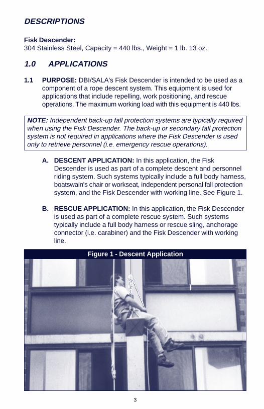
A. DESCENT APPLICATION: In this application, the FiskDescender is used as part of a complete descent and personnelriding system. Such systems typically include a full body harness,boatswain's chair or workseat, independent personal fall protectionsystem, and the Fisk Descender with working line. See Figure 1.
B. RESCUE APPLICATION: In this application, the Fisk Descenderis used as part of a complete rescue system. Such systemstypically include a full body harness or rescue sling, anchorageconnector (i.e. carabiner) and the Fisk Descender with workingline.
Figure 1 - Descent Application

4
1.2 LIMITATIONS: The following application limitations must beconsidered before using this product:
A. CORROSION: Do not leave this equipment for long periods inenvironments where corrosion of metal parts could take place asa result of vapors from organic materials. Use caution whenworking around sewage or fertilizer because of their highconcentration of ammonia, which is very corrosive. Use nearseawater or other corrosive environments may require morefrequent inspections or servicing to ensure corrosion damage isnot affecting the performance of the product.
B. CHEMICAL HAZARDS: Solutions containing acids, alkali, orcaustic chemicals, especially at elevated temperatures, maycause damage to Fisk Descender systems. When working withsuch chemicals, frequent inspection of the entire Fisk Descendermust be completed. Consult DBI/SALA if doubt exists concerningusing this equipment around chemical hazards.
C. HEAT: In general, Fisk Descender systems are not intended foruse in environments where incendiary sparking could cause anexplosion or fire. Use of this equipment is prohibited where thereexists the possibility of the rope coming into contact with powerlines, live cables, etc. Consult the manufacturer for specialapplications of this equipment. Do not use where air temperaturesexceeds 150°F (66°C). Nylon and polyester fibers start todegrade at 260°F (127°C).
D. CAPACITY: The Fisk Descender is designed for use by oneperson only with a combined weight (person, clothing, tools, etc.)of 440 lbs. maximum. In emergency rescue applications, up totwo people may be attached to the Fisk Descender. The workingline used must be reviewed before use to determine compatibility.
E. DESCENT HEIGHT: The Fisk Descender must not be used fordescending from heights exceeding 300 ft. (91m).
F. TRAINING: This equipment is intended to be installed and usedby persons who have been properly trained in its correctapplication and use.
1.3 Refer to national consensus standards (including ANSI A10.14 andANSI Z359.1) applicable local, state, and federal (OSHA)requirements governing this equipment for more information onpersonal fall arrest systems and associated system components.

5
WARNING: Manufacturer's instructions must be followed for proper systemuse and maintenance of this product. Alterations or misuse of this system,or failure to follow instructions, may result in serious injury or death.
2.0 SYSTEM REQUIREMENTS
2.1 COMPATIBILITY OF COMPONENTS: DBI/SALA equipment isdesigned for use with DBI/SALA approved components andsubsystems only. Substitutions or replacements made with non-approved components or subsystems may jeopardize compatibility ofequipment and may effect the safety and reliability of the completesystem. The Fisk Descender rope has been specially selected toprovide the user with the maximum performance and safety. Do notsubstitute with standard safety rope. See section 2.5 for ropeselection and specifications.
2.2 COMPATIBILITY OF CONNECTORS: Connectors are considered tobe compatible with connecting elements when they have beendesigned to work together in such a way that their sizes and shapesdo not cause their gate mechanisms to inadvertently open regardlessof how they become oriented. Contact DBI/SALA if you have anyquestions about compatibility.
Connectors ( hooks, carabiners, and D-rings) must be capable ofsupporting at least 5,000 lbs. (22kN). Connectors must be compatible
If the connecting element that a snap hook (shown) or carabiner attaches to isundersized or irregular in shape, a situation could occur where the connectingelement applies a force to the gate of the snap hook or carabiner. This force maycause the gate (of either a self-locking or a non-locking snap hook) to open,allowing the snap hook or carabiner to disengage from the connecting point.
Figure 2 - Unintentional Disengagement (Roll-out)
1. Force is applied tothe snap hook.
2. The gate presses againstthe connecting ring.
3. The gate opensallowing the snaphook to slip off.
Small ring or othernon-compatiblyshaped element

6
with the anchorage or other system components. Do not useequipment that is not compatible. Non-compatible connectors mayunintentionally disengage. See Figure 2. Connectors must becompatible in size, shape, and strength. Self locking snap hooks andcarabiners are required by ANSI Z359.1 and OSHA.
2.3 Making Connections: Only use self-locking snap hooks andcarabiners with this equipment. Only use connectors that are suitableto each application. Ensure all connections are compatible in size,shape and strength. Do not use equipment that is not compatible.Ensure all connectors are fully closed and locked.
DBI/SALA connectors (snap hooks and carabiners) are designed tobe used only as specified in each product’s user’s instructions. SeeFigure 3 for inappropriate connections. DBI/SALA snap hooks andcarabiners should not be connected:
A. To a D-ring to which another connector is attached.
B. In a manner that would result in a load on the gate.
NOTE: Large throat opening snap hooks should not be connected tostandard size D-rings or similar objects which will result in a load on thegate if the hook or D-ring twists or rotates. Large throat snap hooks aredesigned for use on fixed structural elements such as rebar or crossmembers that are not shaped in a way that can capture the gate of thehook.
Figure 3 - Inappropriate Connections

7
C. In a false engagement, where features that protrude from thesnap hook or carabiner catch on the anchor and without visualconfirmation seems to be fully engaged to the anchor point.
D. To each other.
E. Directly to webbing or rope lanyard or tie-back (unless themanufacturer’s instructions for both the lanyard and connectorspecifically allows such a connection).
F. To any object which is shaped or dimensioned such that the snaphook or carabiner will not close and lock, or that roll-out could occur.
2.4 ANCHORAGE STRENGTH: Anchorages selected for workpositioning or rescue systems (Fisk Descenders) shall have astrength capable of sustaining static loads applied in the directionspermitted by the Fisk Descender of at least 5,000 lbs.
FALL ARREST: Per ANSI Z359.1 - Anchorages selected for personalfall arrest systems (PFAS) shall have a strength capable of sustainingstatic loads in the directions permitted by the PFAS when in use of atleast; (A) 3,600 lbs (16kN) when certification exists (reference ANSIZ359.1 for certification definition), or (B) 5,000 lbs. (22kN) in absenceof certification. When more than one PFAS is attached to an anchorage,the anchorage strengths set forth in (A) or (B) above shall be multipliedby the number of PFAS attached to the anchorage.
Per OSHA 1926.500 and 1910.66 - Anchorages used for attachmentof personal fall arrest systems (PFAS) shall be independent of anyanchorage being used to support or suspend platforms and capableof supporting at least 5,000 lbs (22kN) per user attached, or bedesigned, installed, and used as part of a complete PFAS whichmaintains a safety factor of at least two, and is under the supervisionof a qualified person.
2.5 WORKING LINE: DBI/SALA offers the following three ropes whichmay be used as working lines with the Fisk Descender. See Figure 4:
A. 9503221, Continuous filament polyester cover braided overcontinuous filament nylon core, static kernmantle, 1/2" (12mm)diameter, 10,000 lb. tensile strength.
B. 9503222, Polyester, 12 strand s/braid, 1/2" (12mm) diameter,9,300 lb. tensile strength.
C. 9503223, Nylon, 12 strand s/braid, 1/2" (12mm) diameter, 9,200 lbtensile strength.

8
WARNING: If a rope other than the above is selected for use as a workingline, it must meet the National Fire Protection Association (NFPA)requirements for two person life safety line (see NFPA 1983). Ropes madeof polypropylene, polyethylene or other polyolefins, cotton, sisal, hemp,abaca (manila), or other plant/animal fibers are not to be used. Three strandropes are not recommended. The Fisk Descender should not be used withropes exceeding 5/8" (16mm) diameter.
2.6 BACK-UP FALL PROTECTION EQUIPMENT: The most commonmeans of providing back-up fall protection is by means of an independentlifeline and a rope grab. For descents of less than 130 ft. (30m) aretractable lifeline may provide a convenient means of protection.
If a rope grab and lifeline is selected, DBI/SALA recommends using amobile style rope grab such as the 5001441, which does not requiremanual repositioning as the worker descends. DBI/SALA recommendsusing a full body harness with any fall protection system and a shockabsorbing lanyard with the rope grab system. Lanyard length mustnot exceed 3 ft. (.9m).
The attachment point of the fall protection system (anchorage) mustbe independent of the working line anchorage and be capable ofsupporting 5,000 lbs. (22kN) per person attached. See section 2.3.
The fall protection system selected, including the anchorage, mustmeet Federal OSHA requirements. Reference OSHA 1910.66Appendix C, OSHA 1926.500, ANSI requirements and manufacturer'sinstructions for additional information on use and selection of fallprotection equipment as a system. Extreme caution must beexercised when mixing or selecting components from variousmanufacturers and combining them into one system.
Figure 4 - Working Line
950322195032229503223

9
Equipment which has been subjected to the forces of arresting a fallmust be removed from service immediately and destroyed.
2.7 CONNECTORS: DBI/SALA recommends using self closing, selflocking connectors when making attachments. All connectors mustbe capable of withstanding a 5,000 lb. (22kn) load without failure.DBI/SALA offers a full line of connectors for use with the FiskDescender and associated equipment. See Figure 5.
3.0 OPERATION AND USAGE
WARNING: Do not alter or intentionally misuse this equipment. Consultwith DBI/SALA if using this equipment in combination with components orsubsystems other than those described in this manual. Some subsystemsand components combinations may interfere with the proper operation ofthis equipment.
WARNING: Do not use this equipment if you are unable to tolerate theimpact from a fall arrest. Age and fitness can seriously affect your ability towithstand a fall. Pregnant women and minors must not use this equipment.
3.1 BEFORE EACH USE: Before each use of this or any descent/rescuesystem equipment, carefully inspect it to ensure that it is inserviceable condition. Check for worn or damaged parts. Inspect the
Figure 5 - Compatable Connectors
10
rope for cuts, fraying, burns, etc. Refer to section 5.0 for furtherinspection details. Do not use if inspection reveals an unsafecondition.
3.2 PLANNING: Plan your positioning/rescue system and how it will beused before starting your work. Take into consideration factors thataffect your safety before, during and after a fall. The following listgives some important points to consider when planning your system:
A. ANCHORAGE: Select an anchorage point that is rigid andcapable of supporting 5,000 lbs. (22kN). See section 2.4 andFigure 7. The anchorage location must be carefully selected toreduce possible swing fall hazards and to avoid striking an objectduring a descent or fall.
B. SWING IMPACT: Swing impacts occur when the anchorage pointis not directly above the working point. The force of striking anobject while swinging (horizontal speed of the user due to thependulum affect) can be great and may cause serious injury.Swings can be minimized by working as directly below theanchorage point as possible. Never permit a swing if injury couldoccur. If a swing situation exists in your application, contact DBI/SALA before proceeding.
C. SHARP EDGES: Avoid working where the rope will be in contactwith or abrade against sharp edges. Provide protection for therope when possible.
D. RESCUE: Should a rescue be required, the user (employer)must have a rescue plan and the means at hand to implement it.
WARNING: Read and follow manufacturer's instructions for associatedequipment (full body harness, etc.) used in your positioning/rescue system.
IMPORTANT: For special (Custom) versions of this product, follow theinstructions herein. If enclosed, see attached supplement for additionalinstructions to be followed when using a custom Fisk Descender.
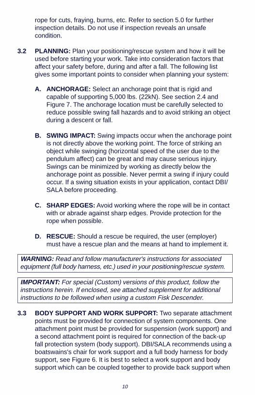
3.3 BODY SUPPORT AND WORK SUPPORT: Two separate attachmentpoints must be provided for connection of system components. Oneattachment point must be provided for suspension (work support) anda second attachment point is required for connection of the back-upfall protection system (body support). DBI/SALA recommends using aboatswains's chair for work support and a full body harness for bodysupport, see Figure 6. It is best to select a work support and bodysupport which can be coupled together to provide back support when
11
working and to prevent the worker from slipping from the chair. Donot attempt to use a waist belt (body belt) as a work support.
IMPORTANT: The use of body belts for positioning/rescue is notrecommended. Body belts increase the risk of injury during fall arrest incomparison to a full body harness. Limited suspension time and thepotential for improperly wearing a body belt may result in added danger tothe user's health.
3.4 SET UP AND INSTALLATION OF LIFELINES: The anchorage pointfor the Fisk Descender's lifeline must be capable of supporting a5,000 lb. minimum static load in the direction of operational pull. Theanchor may be a building structure or other suitable anchoring point.Attach the unit in the following manner:
A. INCORPORATING THIMBLE: DBI/SALA recommends using afigure eight knot followed by an overhand or water knot (used torestrain the free end). To protect the rope, a thimble should beincorporated into the eye of the figure eight knot (1/2" teardropthimble). See Figure 8. Knots other than the figure eight must notbe used as they may reduce rope strength. Contact DBI/SALA ifyou have any questions.
B. CONNECTING TO ANCHORAGE: Select an anchorage ofsufficient strength. See section 3.2.A. Connect the thimble end of
Figure 6 - Work Support and Body Support
12
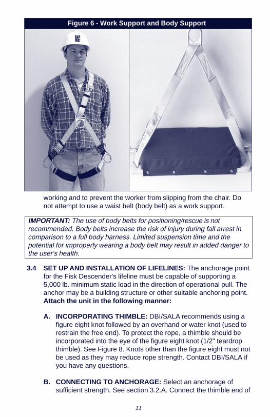
the lifeline either directlyto the anchorage or to atie-off adaptor (i.e.1003000) using a selfclosing/self lockingcarabiner (i.e. 2000523).See Figure 7.
WARNING: Do not wrap theworking line around an objectand attach it back into the line.This will weaken the rope.
C. STABILIZATION:Working on longer linesor under windyconditions (avoidworking in strong winds)may require stabilizationto prevent swinging.Commercially availablesuction cups or slidersattached to the buildingrails are two means commonly used.
3.5 MAKING CONNECTIONS: Self locking snap hooks or self locking/self closing gate carabiners must be used to reduce the possibility ofroll-out when making connections. Do not use hooks or connectorsthat will not completely close over the attachment object. Do not usenon-locking snap hooks. Always follow the manufacturer'sinstructions supplied with each system component.
3.6 OPERATION OF THE FISK DESCENDER
A. ATTACHING THE FISK DESCENDER TO THE WORKINGLINE: The first step in operating the Fisk Descender is learninghow to install it onto the working line. Read and practice thefollowing procedure before attempting to use the descender onthe job. The VHS video provided with this product also containsstep by step instructions for attaching the descender to theworking line.
Step 1. Lay out the working line on a surface in front of you with theend which will be attached to the anchorage to your left. Thisis the “anchor” end. The free end of the working line is the“tag end”. Position this end to your right. Follow Steps 2, 3,4, 5, and 6 as shown in Figures 9, 10, 11, 12, 13, 14, and 15.
1003000
2000523
Figure 7 - Connection to Anchorage

13
Figure 8 - Incorporating Thimble
Step 1 �Step 2
Step 3 Step 4
14
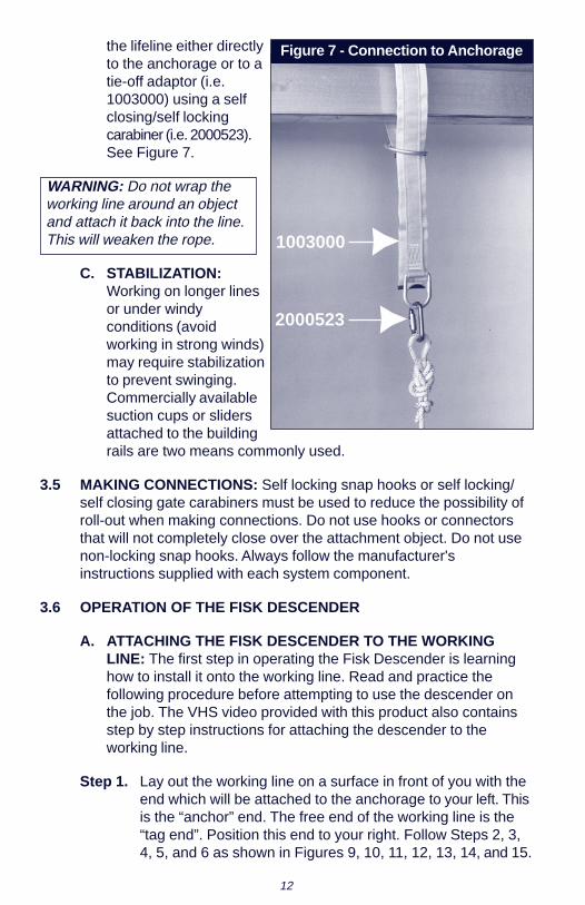
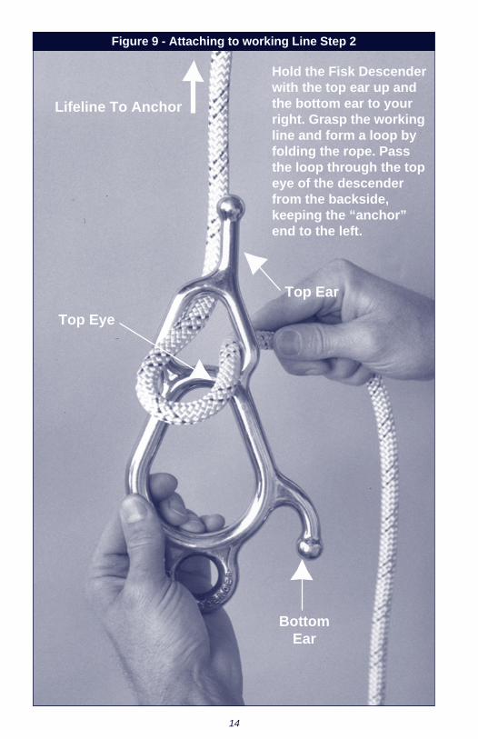
Figure 9 - Attaching to working Line Step 2
Hold the Fisk Descenderwith the top ear up andthe bottom ear to yourright. Grasp the workingline and form a loop byfolding the rope. Passthe loop through the topeye of the descenderfrom the backside,keeping the “anchor”end to the left.
Lifeline To Anchor
Top Eye
Top Ear
BottomEar

15
Figure 10 - Step 2 continued
16
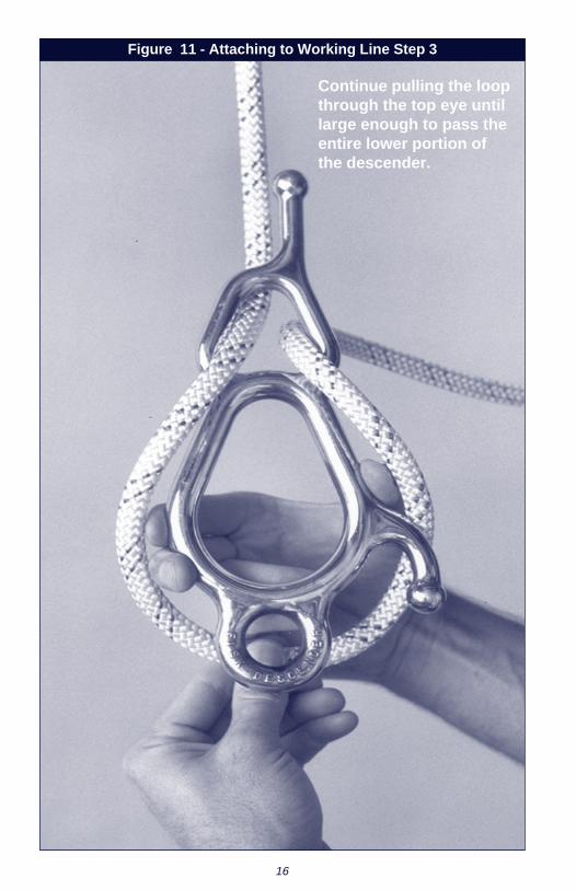
Continue pulling the loopthrough the top eye untillarge enough to pass theentire lower portion ofthe descender.
Figure 11 - Attaching to Working Line Step 3

17
Next, pull the loopthrough the centereye from thebackside.
CenterEye
Figure 12 - Attaching to Working Line Step 4

18
Reference Figure 12.Now slip the foldedloop over the bottomeye. Remove slackline in the descenderby pulling on the tagend of the workingline.
CenterEye
TagEnd
Figure 13 - Attaching to Working Line Step 5
19
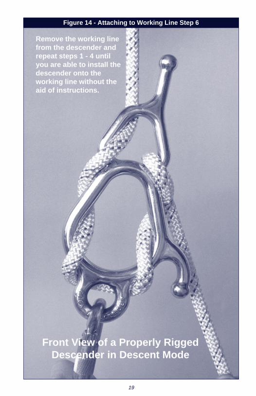
Remove the working linefrom the descender andrepeat steps 1 - 4 untilyou are able to install thedescender onto theworking line without theaid of instructions.
Front View of a Properly RiggedDescender in Descent Mode
Figure 14 - Attaching to Working Line Step 6

20
Figure 15 - Back View
Back View of a Properly RiggedDescender in Descent Mode

21
Wrap tag end ofworking line aroundbottom ear.
Figure 16 - Temporary Lock-Off Step 1
22
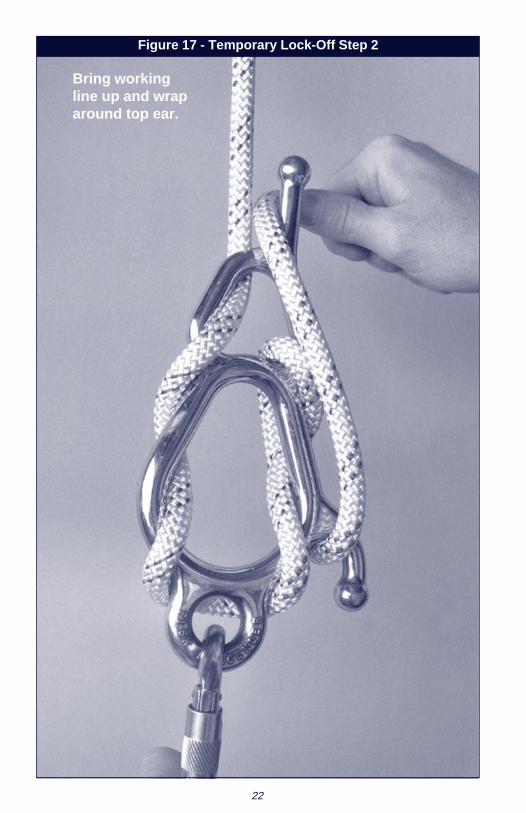
Bring workingline up and wraparound top ear.
Figure 17 - Temporary Lock-Off Step 2
23
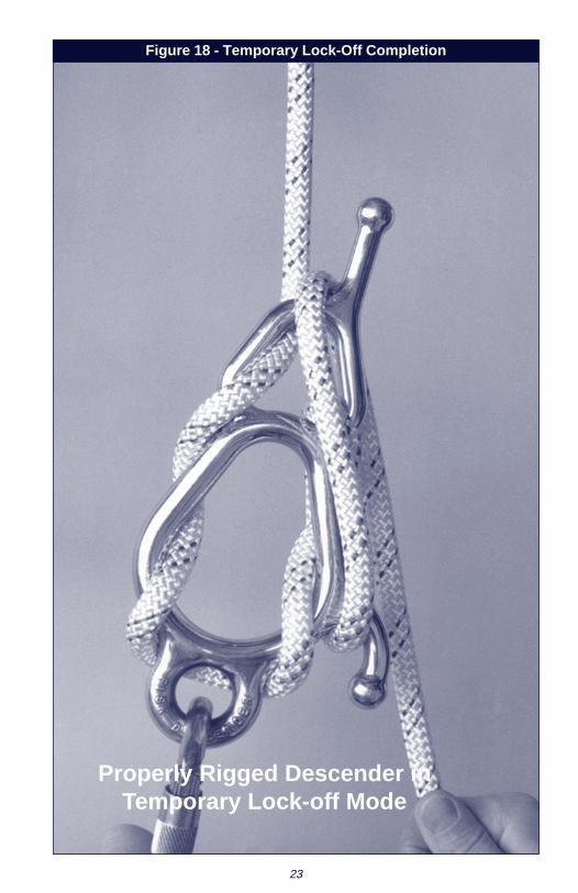
Figure 18 - Temporary Lock-Off Completion
Properly Rigged Descender inTemporary Lock-off Mode

24
Make loop in workingline and then pull theline through the centereye.
Figure 19 - Permanent Lock-Off Step 1

25
Wrap loop of theworking line overthe top ear.
Figure 20 - Permanent Lock-Off Step 2

26
Figure 21 - Permanent Lock-Off Completion
Properly Rigged Descender inPermanent Lock-off Mode

27
IMPORTANT: When learning to use the Fisk Descender rope descentsystem, DBI/SALA recommends selecting a training location that willminimize any fall hazard.
B. CONTROLLING DESCENT SPEED:
1. Attach the Fisk Descender to the working line as described insection 3.6.A.
2. Have an assistant hold the anchor end of the working line and,while applying slight tension to the tag end, pull on the lower eyeof the descender. Notice how varying the tension in the tag endincreases or decreases the force needed to move the descenderdown the working line. When using the Fisk Descender, maintaintension on the tag end of the working line to prevent unwanteddescents.
3. To “lock-off” temporarily at a work position, wrap the tag end ofthe working line around the bottom and top ears. See steps 1, 2,and the completion as shown in Figures 16, 17, and 18. For morepermanent lock-off, wrap the working line as described above,then pull the line through the center eye from the back side andloop over the top ear. See steps 1, 2, and the completion asshown in Figures 19, 20, and 21.
4. To unlock, release the loop from the top ear and unwind theworking line from the top and bottom ears using a circular motion.
IMPORTANT: Always maintain tension on the tag end when locking orunlocking to prevent unwanted descents.
3.7 ASSEMBLY OF THE SYSTEM: Reference Figure 22. The followinggeneral procedure may be used to assemble the Fisk Descenderrope descent system:
1. Inspect system components. See section 5.0.
2. Select an anchorage for the back-up fall protection system andconnect to the anchorage in accordance with the manufacturer'sinstructions. See section 2.4.
3. Using a working line selected in accordance with Section 2.4, connectthe working line to the anchorage. See sections 3.4 A and 3.4 B.
4. Put on your fall protection harness and connect to the fall arrestdevice using the back dorsal D-ring. See section 3.3.

28
5. Attach the Fisk Descender to the working line and lock-off asdescribed in section 3.6.A using the permanent lock-off.
6. Using a self locking connector, connect the boatswain's chair tothe bottom eye of the Fisk Descender.
Figure 22 - Assembly (parts identification)

29
7. Climb into the boatswain's chair and couple the harness to thechair using a second locking connector.
8. To control the descent speed see section 3.6 B.
3.8 USE OF WORKING LINES:
1. Always protect the working line when passing over or around sharpedges. Sharp edges can reduce rope strength by 70% or more.
2. Keep working line clean. See section 6.0.
3. Avoid twisting or kinking working line. If storage bag or box isavailable, it is best to simply feed the rope into the storage bagrather than attempting to coil the rope.
4. Avoid using working lines near acids or alkalies. If working line isused around any chemical or compound watch for signs ofdeterioration.
5. Other than for attaching to the anchorage as described in section3.4 A, do not knot the working line. Knots can reduce ropestrength by 50%.
6. Store working line properly. See section 6.0.
4.0 TRAINING
4.1 TRAINING: The user and the user’s employer, must be trained in thecorrect use and care of this equipment. Both parties must be awareof the operating characteristics, application limits, and consequencesof improper use of this equipment. Consult training video (part no.5901693) for additional training and use information.
IMPORTANT: Training must be conducted without exposing the trainee toa fall hazard. Training should be repeated on a periodic basis.
5.0 INSPECTION
5.1 FREQUENCY:
• Before Each Use: Visually inspect per steps listed in sections5.2, 5.3, and 5.4.
• Monthly: A formal inspection of the Fisk Descender andworking lines should be done by a competent person other than

30
the user. See sections 5.2, 5.3, and 5.4 for guidelines. Recordresults in the Inspection and Maintenance Log in section 9.0.
IMPORTANT: Consult individual subsystem user instruction manuals forinspection frequency and steps.
IMPORTANT: Extreme working conditions (harsh environment, prolongeduse, etc.) may require increasing the frequency of inspections.
5.2 INSPECTION STEPS FOR THE FISK DESCENDER:
STEP 1: Inspect for wear along the entire Fisk Descender unit.
STEP 2: Inspect for cracks and deformation.
STEP 3: Inspect for burrs or sharp edges which may snag or cut theworking line. Small burrs may be removed using a metal fileor emery cloth.
5.3 INSPECTION STEPS FOR THE WORKING LINES:
STEP 1: Inspect the lifeline hardware (thimble). The thimble must notbe damaged, broken, distorted, or have any sharp edges,burrs, cracks, worn parts, or corrosion.
STEP 2: Inspect the rope for concentrated wear. The rope must befree of frayed strands and broken yarns, cuts and abrasions,burns, and discoloration. Check for kinks and hockles in theworking line.
STEP 3: Check for chemical or heat damage (brown or brittle areas).Inspect for heavily soiled areas, grit, oil, grease, paint, etc.
STEP 4: Check for ultraviolet damage indicated by discoloration andthe presence of splinters and slivers on the rope surface).
STEP 5: Untie any knots and inspect the rope in the knot area.
5.4 If inspection or operation reveals a defective condition, remove theFisk Descender from service immediately and contact an authorizedservice center for repair.

31
6.0 MAINTENANCE, SERVICING, STORAGE
6.1 Periodically clean the exterior of the Fisk Descender using water anda mild soap solution.
6.2 Clean rope with water and mild soap solution. Rinse and thoroughlyair dry. Do not force dry with heat. Immediately wash entire ropeassembly if it has been exposed to acidic vapors or materials.
WARNING: If rope comes in contact with any acids, remove from serviceand wash with a water and mild soap solution. Do not return the system toservice without first being inspected by a qualified inspector. Acids in contactwith rope for extended periods of time can weaken rope without visibleevidence of damage. Only a qualified inspector can determine rope status.
6.3 Store Fisk Descender and working lines in cool, dry, cleanenvironment out of direct sunlight. Avoid areas where chemicalvapors may exist. Inspect the Fisk Descender and working lines afterany period of extended storage.
7.0 SPECIFICATIONS
Fisk Descender 304 Stainless Steel, investment cast strength.Wieght 1 lb. 13 oz. Capacity 440 lbs. maximum (oneperson).
Rope 9503221 Static - Kernmantle, 1/2" (12 mm) diameter, 10,000lb. (44,4kn) average strength, constructed ofcontinuous filament polyester cover braided overcontinuous filament nylon core. Elongationapproximately 2 % of length @ 440 lbs. (200kg).
Rope 9503222 12 strand with braid, 1/2" (12mm) diameter, 9,300 lb.(41.3kn) average strength, constructed of hightenacity polyester fibers. Elongation approximately3.5% of length @ 440 lbs. (200kg).
Rope 9503223 12 strand with braid, 1/2" (12mm) diameter, 9,200 lb.(40.8kn) average strength, constructed of hightenacity nylon type 6.6. Elongation approximately3.5% of length @ 440 lbs. (200kg).

32
8.0 INSPECTION AND MAINTENANCE LOG
SERIAL NUMBER: ____________________________________________
MODEL NUMBER: ____________________________________________
DATE PURCHASED: __________________________________________
ETADNOITCEPSNI SMETINOITCEPSNIDETON
NOITCAEVITCERROC ECNANETNIAMDEMROFREP
:yBdevorppA
:yBdevorppA
:yBdevorppA
:yBdevorppA
:yBdevorppA
:yBdevorppA
:yBdevorppA
:yBdevorppA
:yBdevorppA
:yBdevorppA
:yBdevorppA
:yBdevorppA

33
8.0 INSPECTION AND MAINTENANCE LOG
SERIAL NUMBER: ____________________________________________
MODEL NUMBER: ____________________________________________
DATE PURCHASED: __________________________________________
ETADNOITCEPSNI SMETINOITCEPSNIDETON
NOITCAEVITCERROC ECNANETNIAMDEMROFREP
:yBdevorppA
:yBdevorppA
:yBdevorppA
:yBdevorppA
:yBdevorppA
:yBdevorppA
:yBdevorppA
:yBdevorppA
:yBdevorppA
:yBdevorppA
:yBdevorppA
:yBdevorppA

34
8.0 INSPECTION AND MAINTENANCE LOG
SERIAL NUMBER: ____________________________________________
MODEL NUMBER: ____________________________________________
DATE PURCHASED: __________________________________________
ETADNOITCEPSNI SMETINOITCEPSNIDETON
NOITCAEVITCERROC ECNANETNIAMDEMROFREP
:yBdevorppA
:yBdevorppA
:yBdevorppA
:yBdevorppA
:yBdevorppA
:yBdevorppA
:yBdevorppA
:yBdevorppA
:yBdevorppA
:yBdevorppA
:yBdevorppA
:yBdevorppA

WARRANTY
Equipment offered by DBI/SALA are warranted against factory defects inworkmanship and materials for a period of two years from date of purchase.Upon notice in writing, DBI/SALA will promptly repair or replace all defectiveitems. DBI/SALA reserves the right to elect to have any defective itemreturned to its plant for inspection before making a repair or replacement.Warranty does not cover equipment damages resulting from abuse, damagein transit, or other damage beyond the control of DBI/SALA. This warrantyapplies only to the original purchaser and is the only one applicable to ourproducts, and is in lieu of all other warranties, expressed or implied.
USA Canada3965 Pepin Avenue 260 Export BoulevardRed Wing, MN 55066-1837 Mississauga, Ontario L5S 1Y9Toll Free: 800-328-6146 Toll Free: 800-387-7484Phone: (651) 388-8282 Phone: (905) 795-9333Fax: (651) 388-5065 Fax: (905) 795-8777www.salagroup.com
Form: 5902142Rev: D
��������������
Certificate No. FM 39709