Embed Size (px)
Citation preview

© Copyright 2002, DB Industries, Inc.
User Instruction ManualLAD-SAF® Flexible CableLadder Safety Systems
This manual is intended to be used as part of an
employee training program as required by OSHA.
WARNING: These instructions must be provided to the user and installer of this equipment. The user and installer ofthis equipment must read and understand these instructions before use or installation. Follow the manufacturer’sinstructions for safety equipment used with this system. Follow these instructions for proper use, inspection, andmaintenance of this equipment. This equipment is intended to be used as part of a complete LAD-SAF® ladder safetysystem. Alterations, substitutions, or misuse of this equipment, or failure to follow instructions, may result in seriousinjury or death.
IMPORTANT: If you have questions on the installation, use, maintenance, or suitability of this equipment for yourapplication, contact DBI/SALA.
IMPORTANT: Before using this equipment, record the product identification information from the installation andservice label in the maintenance log in section 9.0 of this manual.


3
Table of Contents
1.0 Applications .................................................................................................................... 41.1 Purpose .................................................................................................................41.2 Limitations..............................................................................................................41.3 Applicable Standards ............................................................................................. 4
2.0 System Requirements2.1 Compatibility of Components and Subsystems .....................................................42.2 Compatibility of Connectors ................................................................................... 42.3 Load Requirements for Structure and Bracket Connections.................................. 4
3.0 System Installation .........................................................................................................53.1 General .................................................................................................................. 53.2 Welding Recommendations ................................................................................... 53.3 Top Bracket Installation.........................................................................................143.4 Installation of Carrier Cable to Top Bracket .......................................................... 203.5 Installation of Cable Guide, All Models .................................................................203.6 Installation of Bottom Bracket and Carrier Cable Tension Adjustment .................. 213.7 Final Installation Inspection and System Identification .........................................25
4.0 LAD-SAF® System Use ..................................................................................................254.1 Before Each Use...................................................................................................254.2 Plan.......................................................................................................................264.3 Training .................................................................................................................264.4 Connecting the Ladder Safety Sleeve to the Harness .......................................... 264.5 Connecting the Ladder Safety Sleeve to the Carrier Cable .................................. 264.6 Climbing on the System ........................................................................................27
5.0 Inspection.......................................................................................................................275.1 Frequency .............................................................................................................275.2 Inspection Guidelines for LAD-SAF® System Installation .....................................285.3 Inspection Guidelines for LAD-SAF® Ladder Safety Sleeve ................................. 285.4 If Inspection Reveals an Unsafe Condition ...........................................................28
6.0 Maintenance, Servicing, Storage ................................................................................. 28
7.0 Specifications ................................................................................................................29
8.0 Labeling ..........................................................................................................................29
9.0 Inspection and Maintenance Log ................................................................................. 30

4
1.0 APPLICATIONS
1.1 PURPOSE: LAD-SAF ® flexible cable ladder safety systems are designed to provide protection against falling forpersons connected to the system while climbing fixed ladders or similar climbing structures.
A. APPLICATIONS: LAD-SAF® systems include installations on fixed ladders or ladder like climbing surfacesthat are part of a structure. Examples include; water tank ladders, mono poles (wood, steel, or concrete)buildings, manways, antenna structures, and towers.
1.2 LIMITATIONS: LAD-SAF® systems are not intended to be installed on portable ladders. These systems aredesigned for use on ladders that are generally vertical. Ladders must be at least 75 degrees from horizontal forproper system operation, except for curved top bracket installations. The following application limitations must beconsidered before installing or using the LAD-SAF® system.
A. LADDER STRUCTURE: The ladder structure to which the system is installed must be capable ofwithstanding the loads applied by the system in the event of a fall.
B. SYSTEM CAPACITY: The number of users allowed on the system at one time varies depending on the typeof system and installation. Generally, system capacities range from one to four users. See sections 2.0 and3.0 for more information on capacity limitations. System capacities are based on a maximum user’s weight,including tools and clothing, of 310 lbs.
C. ENVIRONMENTAL HAZARDS: Use of this equipment in areas with environmental hazards may require thatadditional precautions be taken to reduce the possibility of injury to the user or damage to the equipment.Hazards may include, but are not limited to: high heat caused by welding or metal cutting; caustic chemicals;seawater; high voltage power lines; explosive or toxic gases; moving machinery; sharp edges.
D. COMPONENT COMPATIBILITY: LAD-SAF® systems must be installed and used as a complete system.Only DBI/SALA’s detachable cable sleeve may be used with this system. DBI/SALA recommends using a fullbody harness with a front attachment for ladder climbing. A body belt is not recommended for use with theLAD-SAF® system. If a fall occurs when using a body belt it may cause unintentional release and possiblesuffocation because of improper body support. Substitutions of equipment or system components must notbe made without the written consent of DBI/SALA.
E. TRAINING: This equipment is intended to be installed and used by persons who have been trained in itscorrect application and use.
1.3 Refer to applicable local, state, and federal (OSHA) requirements governing this equipment for more informationon ladder safety systems and associated components, including OSHA 1910.27.
2.0 SYSTEM REQUIREMENTS
2.1 COMPATIBILITY OF COMPONENTS AND SUBSYSTEMS: This equipment is designed for use with DBI/SALAapproved components and subsystems. The use of non-approved components and subsystems may jeopardizecompatibility of equipment, and could affect the safety and reliability of the complete system.
2.2 COMPATIBILITY OF CONNECTORS: Connectors used with this system (hooks, carabiners, D-rings) must becapable of supporting a minimum of 5,000 lbs. Use caution to assure compatibility of hooks and the connectionpoint. See section 4.4 on making connections. Non-compatible connectors may unintentionally disengage (roll-out). Connectors must be compatible in size, shape, and strength. Self closing/self locking connectors are highlyrecommended by DBI/SALA.
2.3 LOAD REQUIREMENTS FOR STRUCTURE AND BRACKET CONNECTIONS: The climbing structure to whichthe LAD-SAF® system is installed must be capable of supporting the loads imposed by the system. Forcalculation purposes the required bracket load may be assumed to be distributed evenly between the number ofrung attachments. For example; the 6116280 top bracket is supplied with three rung connections. The loadrequired for each rung for a single user system is 1,125 lbs. per rung (3,375 lbs./3).
A. TOP BRACKET: The top bracket connection loads include system pretension and forces associated with
5
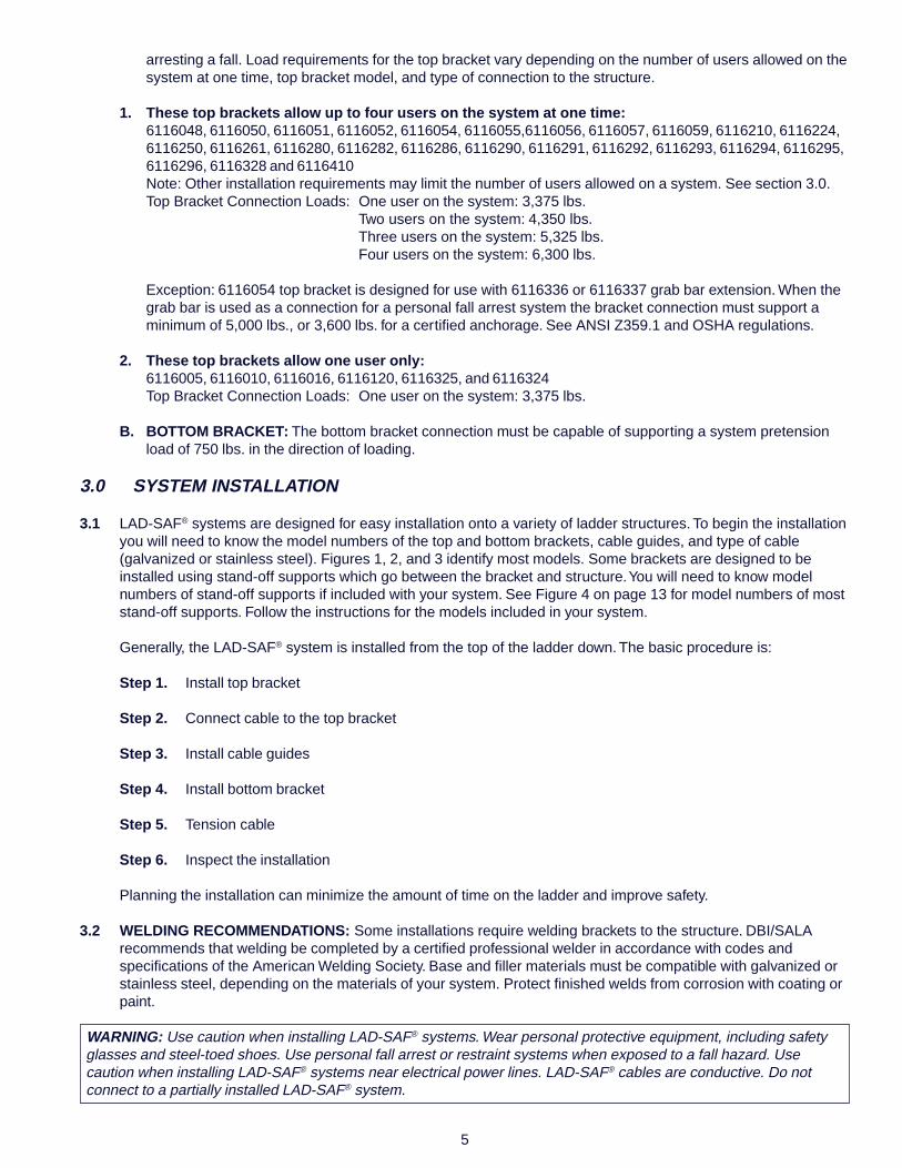
arresting a fall. Load requirements for the top bracket vary depending on the number of users allowed on thesystem at one time, top bracket model, and type of connection to the structure.
1. These top brackets allow up to four users on the system at one time:6116048, 6116050, 6116051, 6116052, 6116054, 6116055,6116056, 6116057, 6116059, 6116210, 6116224,6116250, 6116261, 6116280, 6116282, 6116286, 6116290, 6116291, 6116292, 6116293, 6116294, 6116295,6116296, 6116328 and 6116410Note: Other installation requirements may limit the number of users allowed on a system. See section 3.0.Top Bracket Connection Loads: One user on the system: 3,375 lbs.
Two users on the system: 4,350 lbs.Three users on the system: 5,325 lbs.Four users on the system: 6,300 lbs.
Exception: 6116054 top bracket is designed for use with 6116336 or 6116337 grab bar extension. When thegrab bar is used as a connection for a personal fall arrest system the bracket connection must support aminimum of 5,000 lbs., or 3,600 lbs. for a certified anchorage. See ANSI Z359.1 and OSHA regulations.
2. These top brackets allow one user only:6116005, 6116010, 6116016, 6116120, 6116325, and 6116324Top Bracket Connection Loads: One user on the system: 3,375 lbs.
B. BOTTOM BRACKET: The bottom bracket connection must be capable of supporting a system pretensionload of 750 lbs. in the direction of loading.
3.0 SYSTEM INSTALLATION
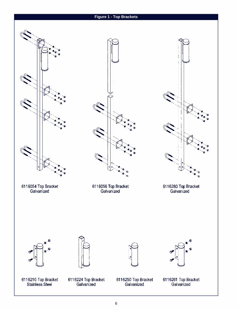
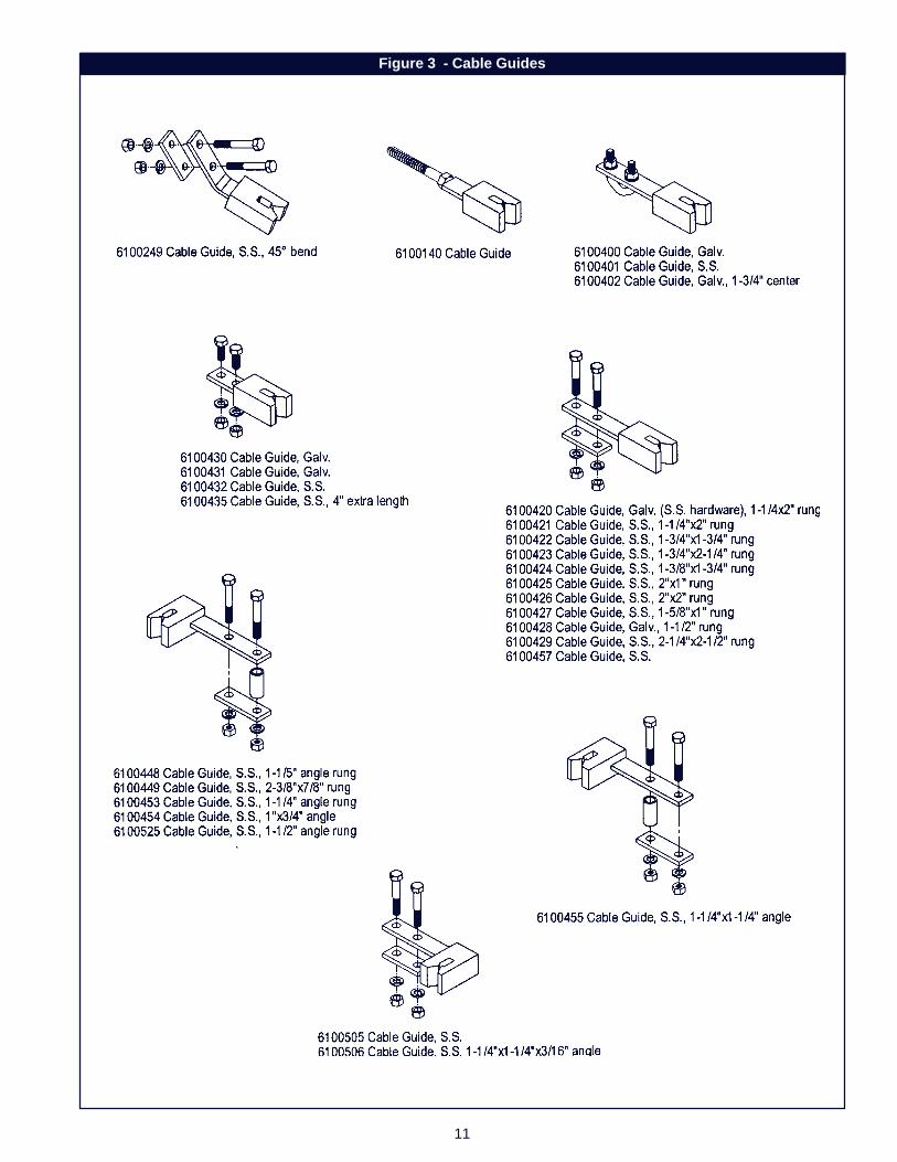
3.1 LAD-SAF® systems are designed for easy installation onto a variety of ladder structures. To begin the installationyou will need to know the model numbers of the top and bottom brackets, cable guides, and type of cable(galvanized or stainless steel). Figures 1, 2, and 3 identify most models. Some brackets are designed to beinstalled using stand-off supports which go between the bracket and structure. You will need to know modelnumbers of stand-off supports if included with your system. See Figure 4 on page 13 for model numbers of moststand-off supports. Follow the instructions for the models included in your system.
Generally, the LAD-SAF® system is installed from the top of the ladder down. The basic procedure is:
Step 1. Install top bracket
Step 2. Connect cable to the top bracket
Step 3. Install cable guides
Step 4. Install bottom bracket
Step 5. Tension cable
Step 6. Inspect the installation
Planning the installation can minimize the amount of time on the ladder and improve safety.
3.2 WELDING RECOMMENDATIONS: Some installations require welding brackets to the structure. DBI/SALArecommends that welding be completed by a certified professional welder in accordance with codes andspecifications of the American Welding Society. Base and filler materials must be compatible with galvanized orstainless steel, depending on the materials of your system. Protect finished welds from corrosion with coating orpaint.
WARNING: Use caution when installing LAD-SAF® systems. Wear personal protective equipment, including safetyglasses and steel-toed shoes. Use personal fall arrest or restraint systems when exposed to a fall hazard. Usecaution when installing LAD-SAF® systems near electrical power lines. LAD-SAF® cables are conductive. Do notconnect to a partially installed LAD-SAF® system.
6
Figure 1 - Top Brackets
7
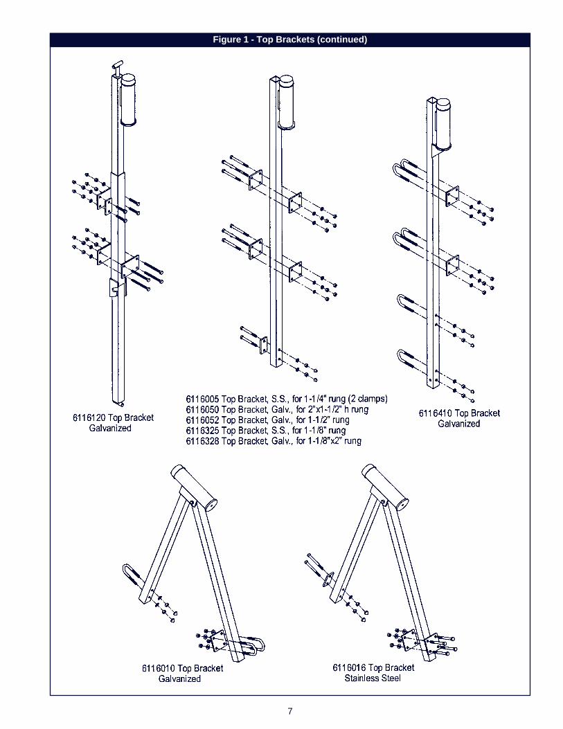
Figure 1 - Top Brackets (continued)
8
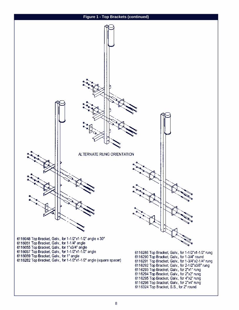
Figure 1 - Top Brackets (continued)
9
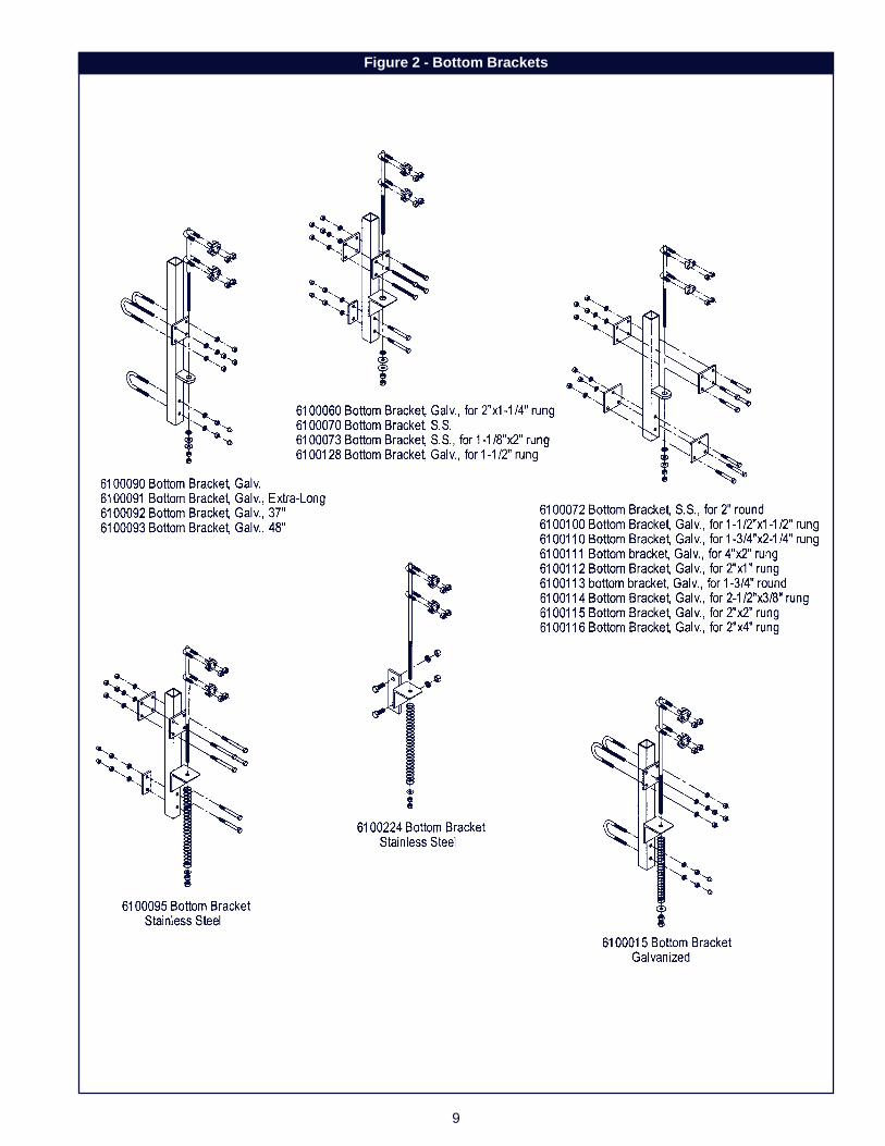
Figure 2 - Bottom Brackets
10
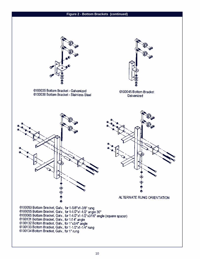
Figure 2 - Bottom Brackets (continued)
11
Figure 3 - Cable Guides
12
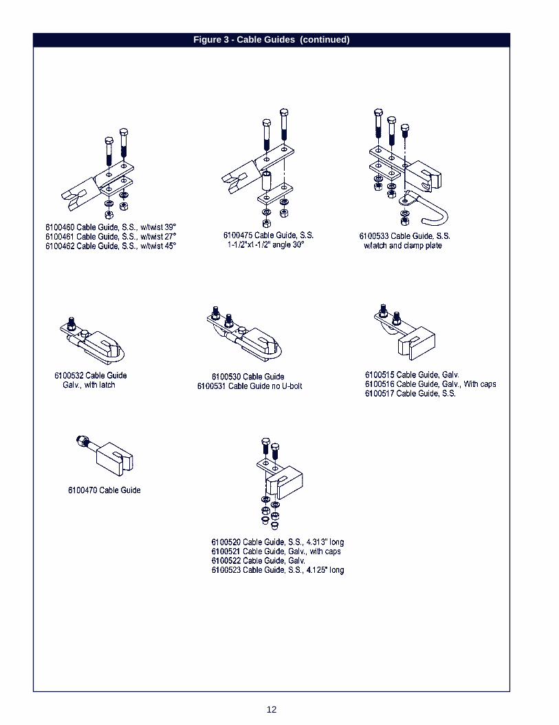
Figure 3 - Cable Guides (continued)

13
Figure 4 - Stand-offs
14
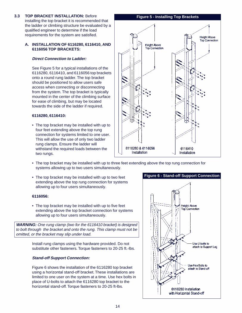
3.3 TOP BRACKET INSTALLATION: Beforeinstalling the top bracket it is recommended thatthe ladder or climbing structure be evaluated by aqualified engineer to determine if the loadrequirements for the system are satisfied.
A. INSTALLATION OF 6116280, 6116410, AND6116056 TOP BRACKETS:
Direct Connection to Ladder:
See Figure 5 for a typical installations of the6116280, 6116410, and 6116056 top bracketsonto a round rung ladder. The top bracketshould be positioned to allow users safeaccess when connecting or disconnectingfrom the system. The top bracket is typicallymounted in the center of the climbing surfacefor ease of climbing, but may be locatedtowards the side of the ladder if required.
6116280, 6116410:
• The top bracket may be installed with up tofour feet extending above the top rungconnection for systems limited to one user.This will allow the use of only two ladderrung clamps. Ensure the ladder willwithstand the required loads between thetwo rungs.
• The top bracket may be installed with up to three feet extending above the top rung connection forsystems allowing up to two users simultaneously.
• The top bracket may be installed with up to two feetextending above the top rung connection for systemsallowing up to four users simultaneously.
6116056:
• The top bracket may be installed with up to five feetextending above the top bracket connection for systemsallowing up to four users simultaneously.
WARNING: One rung clamp (two for the 6116410 bracket) is designedto bolt through the bracket and onto the rung. This clamp must not beomitted, or the bracket may slip under load.
Install rung clamps using the hardware provided. Do notsubstitute other fasteners. Torque fasteners to 20-25 ft.-lbs.
Stand-off Support Connection:
Figure 6 shows the installation of the 6116280 top bracketusing a horizontal stand-off bracket. These installations arelimited to one user on the system at a time. Use hex bolts inplace of U-bolts to attach the 6116280 top bracket to thehorizontal stand-off. Torque fasteners to 20-25 ft-lbs.
Figure 5 - Installing Top Brackets
Figure 6 - Stand-off Support Connection
15
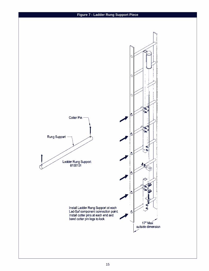
Figure 7 - Ladder Rung Support Piece
16
Ladder Rung Support:
Figure 7 shows the installation of the 6100151 ladderrung support piece. The rung support is used to supporthollow rungs with a minimum inside diameter between1" and 1-1/8". In some applications the ladder rungsmust be supported in order to meet required strengthsand to prevent rung collapse. The rung support piececan be used on those rungs supporting top brackets,cable guide and bottom brackets.
The ladder or climbing structure must be evaluated by aqualified engineer to determine if the load requirementsfor the system with rung supports are satisfied.
Install ladder rung support at each LAD-SAF®
component connection point.
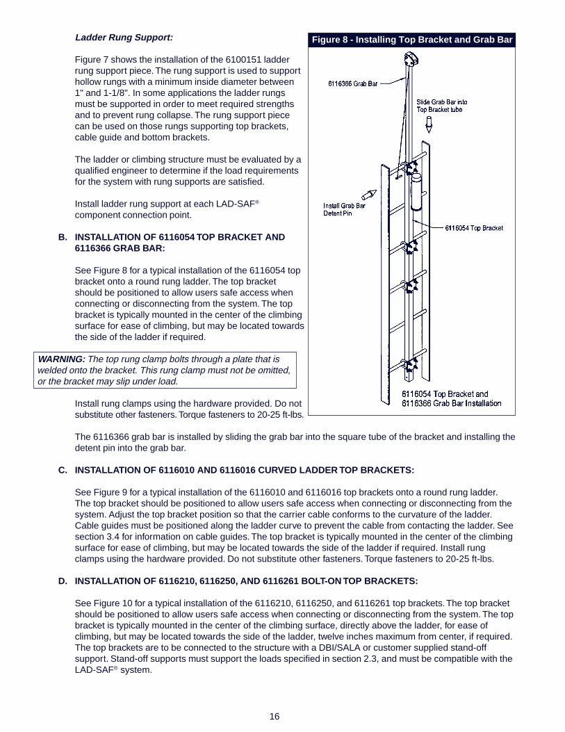
B. INSTALLATION OF 6116054 TOP BRACKET AND6116366 GRAB BAR:
See Figure 8 for a typical installation of the 6116054 topbracket onto a round rung ladder. The top bracketshould be positioned to allow users safe access whenconnecting or disconnecting from the system. The topbracket is typically mounted in the center of the climbingsurface for ease of climbing, but may be located towardsthe side of the ladder if required.
WARNING: The top rung clamp bolts through a plate that iswelded onto the bracket. This rung clamp must not be omitted,or the bracket may slip under load.
Install rung clamps using the hardware provided. Do notsubstitute other fasteners. Torque fasteners to 20-25 ft-lbs.
The 6116366 grab bar is installed by sliding the grab bar into the square tube of the bracket and installing thedetent pin into the grab bar.
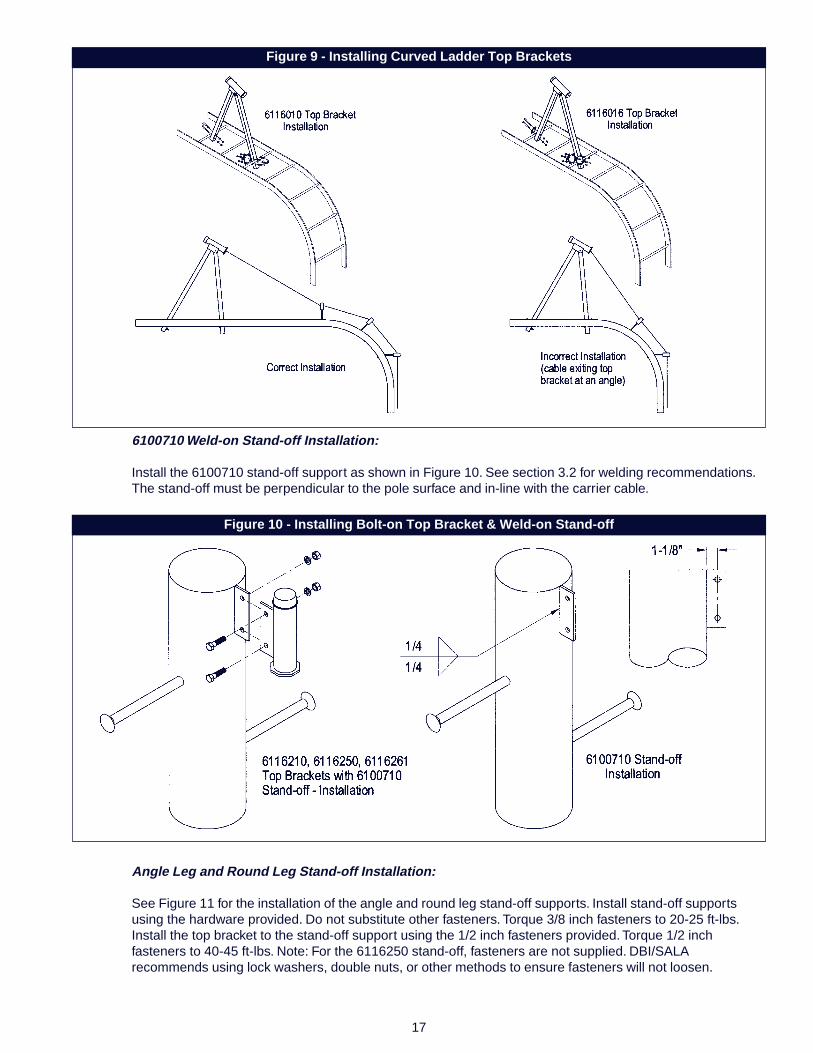
C. INSTALLATION OF 6116010 AND 6116016 CURVED LADDER TOP BRACKETS:
See Figure 9 for a typical installation of the 6116010 and 6116016 top brackets onto a round rung ladder.The top bracket should be positioned to allow users safe access when connecting or disconnecting from thesystem. Adjust the top bracket position so that the carrier cable conforms to the curvature of the ladder.Cable guides must be positioned along the ladder curve to prevent the cable from contacting the ladder. Seesection 3.4 for information on cable guides. The top bracket is typically mounted in the center of the climbingsurface for ease of climbing, but may be located towards the side of the ladder if required. Install rungclamps using the hardware provided. Do not substitute other fasteners. Torque fasteners to 20-25 ft-lbs.
D. INSTALLATION OF 6116210, 6116250, AND 6116261 BOLT-ON TOP BRACKETS:
See Figure 10 for a typical installation of the 6116210, 6116250, and 6116261 top brackets. The top bracketshould be positioned to allow users safe access when connecting or disconnecting from the system. The topbracket is typically mounted in the center of the climbing surface, directly above the ladder, for ease ofclimbing, but may be located towards the side of the ladder, twelve inches maximum from center, if required.The top brackets are to be connected to the structure with a DBI/SALA or customer supplied stand-offsupport. Stand-off supports must support the loads specified in section 2.3, and must be compatible with theLAD-SAF® system.
Figure 8 - Installing Top Bracket and Grab Bar
17
6100710 Weld-on Stand-off Installation:
Install the 6100710 stand-off support as shown in Figure 10. See section 3.2 for welding recommendations.The stand-off must be perpendicular to the pole surface and in-line with the carrier cable.
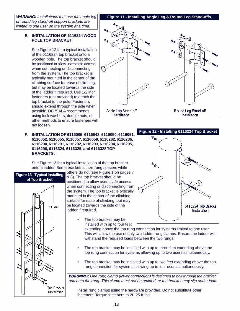
Angle Leg and Round Leg Stand-off Installation:
See Figure 11 for the installation of the angle and round leg stand-off supports. Install stand-off supportsusing the hardware provided. Do not substitute other fasteners. Torque 3/8 inch fasteners to 20-25 ft-lbs.Install the top bracket to the stand-off support using the 1/2 inch fasteners provided. Torque 1/2 inchfasteners to 40-45 ft-lbs. Note: For the 6116250 stand-off, fasteners are not supplied. DBI/SALArecommends using lock washers, double nuts, or other methods to ensure fasteners will not loosen.
Figure 9 - Installing Curved Ladder Top Brackets
Figure 10 - Installing Bolt-on Top Bracket & Weld-on Stand-off
18
WARNING: Installations that use the angle legor round leg stand-off support brackets arelimited to one user on the system at a time.
E. INSTALLATION OF 6116224 WOODPOLE TOP BRACKET:
See Figure 12 for a typical installationof the 6116224 top bracket onto awooden pole. The top bracket shouldbe positioned to allow users safe accesswhen connecting or disconnectingfrom the system. The top bracket istypically mounted in the center of theclimbing surface for ease of climbing,but may be located towards the sideof the ladder if required. Use 1/2 inchfasteners (not provided) to attach thetop bracket to the pole. Fastenersshould extend through the pole whenpossible. DBI/SALA recommendsusing lock washers, double nuts, orother methods to ensure fasteners willnot loosen.
F. INSTALLATION OF 6116005, 6116048, 6116050, 6116051,6116052, 6116055, 6116057, 6116059, 6116282, 6116286,6116290, 6116291, 6116292, 6116293, 6116294, 6116295,6116296, 6116324, 6116325, and 6116328 TOPBRACKETS:
See Figure 13 for a typical installation of the top bracketonto a ladder. Some brackets utilize rung spacers while
others do not (see Figure 1 on pages 7& 8). The top bracket should bepositioned to allow users safe accesswhen connecting or disconnecting fromthe system. The top bracket is typicallymounted in the center of the climbingsurface for ease of climbing, but maybe located towards the side of theladder if required.
Figure 11 - Installing Angle Leg & Round Leg Stand-offs
Figure 12 - Installing 6116224 Top Bracket
Figure 13 - Typical Installingof Top Bracket
• The top bracket may beinstalled with up to four feetextending above the top rung connection for systems limited to one user.This will allow the use of only two ladder rung clamps. Ensure the ladder willwithstand the required loads between the two rungs.
• The top bracket may be installed with up to three feet extending above thetop rung connection for systems allowing up to two users simultaneously.
• The top bracket may be installed with up to two feet extending above the toprung connection for systems allowing up to four users simultaneously.
WARNING: One rung clamp (lower connection) is designed to bolt through the bracketand onto the rung. This clamp must not be omitted, or the bracket may slip under load.
Install rung clamps using the hardware provided. Do not substitute otherfasteners. Torque fasteners to 20-25 ft-lbs.
19
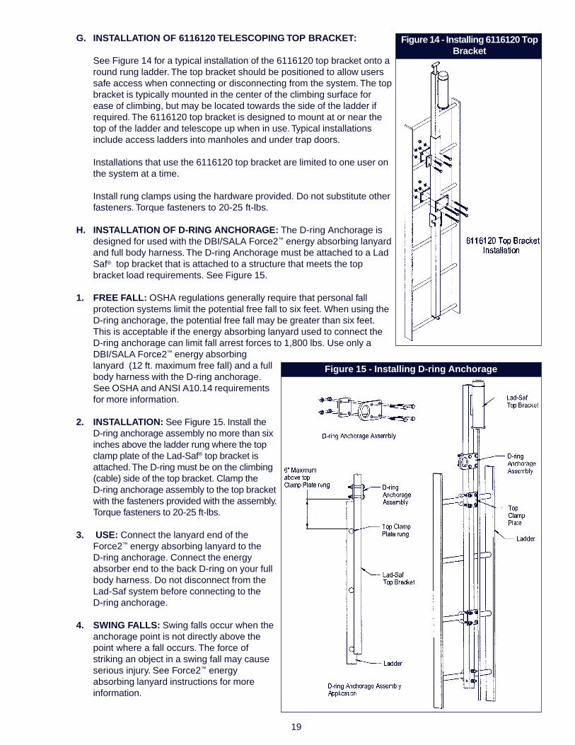
G. INSTALLATION OF 6116120 TELESCOPING TOP BRACKET:
See Figure 14 for a typical installation of the 6116120 top bracket onto around rung ladder. The top bracket should be positioned to allow userssafe access when connecting or disconnecting from the system. The topbracket is typically mounted in the center of the climbing surface forease of climbing, but may be located towards the side of the ladder ifrequired. The 6116120 top bracket is designed to mount at or near thetop of the ladder and telescope up when in use. Typical installationsinclude access ladders into manholes and under trap doors.
Installations that use the 6116120 top bracket are limited to one user onthe system at a time.
Install rung clamps using the hardware provided. Do not substitute otherfasteners. Torque fasteners to 20-25 ft-lbs.
H. INSTALLATION OF D-RING ANCHORAGE: The D-ring Anchorage isdesigned for used with the DBI/SALA Force2™ energy absorbing lanyardand full body harness. The D-ring Anchorage must be attached to a LadSaf® top bracket that is attached to a structure that meets the topbracket load requirements. See Figure 15.
1. FREE FALL: OSHA regulations generally require that personal fallprotection systems limit the potential free fall to six feet. When using theD-ring anchorage, the potential free fall may be greater than six feet.This is acceptable if the energy absorbing lanyard used to connect theD-ring anchorage can limit fall arrest forces to 1,800 lbs. Use only aDBI/SALA Force2™ energy absorbinglanyard (12 ft. maximum free fall) and a fullbody harness with the D-ring anchorage.See OSHA and ANSI A10.14 requirementsfor more information.
2. INSTALLATION: See Figure 15. Install theD-ring anchorage assembly no more than sixinches above the ladder rung where the topclamp plate of the Lad-Saf® top bracket isattached. The D-ring must be on the climbing(cable) side of the top bracket. Clamp theD-ring anchorage assembly to the top bracketwith the fasteners provided with the assembly.Torque fasteners to 20-25 ft-lbs.
3. USE: Connect the lanyard end of theForce2™ energy absorbing lanyard to theD-ring anchorage. Connect the energyabsorber end to the back D-ring on your fullbody harness. Do not disconnect from theLad-Saf system before connecting to theD-ring anchorage.
4. SWING FALLS: Swing falls occur when theanchorage point is not directly above thepoint where a fall occurs. The force ofstriking an object in a swing fall may causeserious injury. See Force2™ energyabsorbing lanyard instructions for moreinformation.
Figure 14 - Installing 6116120 TopBracket
Figure 15 - Installing D-ring Anchorage
20
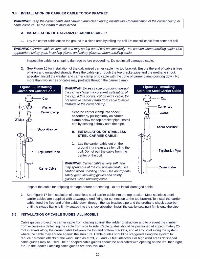
3.4 INSTALLATION OF CARRIER CABLE TO TOP BRACKET:
WARNING: Keep the carrier cable and carrier clamp clean during installation. Contamination of the carrier clamp orcable could cause the clamp to malfunction.
A. INSTALLATION OF GALVANIZED CARRIER CABLE:
1. Lay the carrier cable out on the ground in a clean area by rolling the coil. Do not pull cable from center of coil.
WARNING: Carrier cable is very stiff and may spring out of coil unexpectedly. Use caution when unrolling cable. Useappropriate safety gear, including gloves and safety glasses, when unrolling cable.
Inspect the cable for shipping damage before proceeding. Do not install damaged cable.
2. See Figure 16 for installation of the galvanized carrier cable into top bracket. Ensure the end of cable is freeof kinks and unraveled strands. Pass the cable up through the top bracket pipe and the urethane shockabsorber. Install the washer and carrier clamp onto cable with the cone of carrier clamp pointing down. Nomore than two inches of cable may protrude through the carrier clamp.
Figure 16 - InstallingGalvanized Carrier Cable
Figure 17 - InstallingStainless Steel Carrier Cable
WARNING: Excess cable protruding throughthe carrier clamp may prevent installation ofthe cap. If this occurs, cut off extra cable. Donot remove carrier clamp from cable to avoiddamage to the carrier clamp.
Seat the carrier clamp into shockabsorber by pulling firmly on carrierclamp below the top bracket pipe. Installcap by seating it firmly onto the pipe.
B. INSTALLATION OF STAINLESSSTEEL CARRIER CABLE:
1. Lay the carrier cable out on theground in a clean area by rolling thecoil. Do not pull the cable from thecenter of the coil.
WARNING: Carrier cable is very stiff, andmay spring out of the coil unexpectedly. Usecaution when unrolling cable. Use appropriatesafety gear, including gloves and safetyglasses, when unrolling cable.
Inspect the cable for shipping damage before proceeding. Do not install damaged cable.
2. See Figure 17 for installation of a stainless steel carrier cable into the top bracket. Most stainless steelcarrier cables are supplied with a swagged end fitting for connection to the top bracket. To install the carriercable, feed the free end of the cable down through the top bracket pipe and the urethane shock absorberuntil the swage fitting is firmly seated into the shock absorber. Install the cap by seating it firmly onto the pipe.
3.5 INSTALLATION OF CABLE GUIDES, ALL MODELS:
Cable guides protect the carrier cable from chafing against the ladder or structure and to prevent the climberfrom excessively deflecting the cable from side to side. Cable guides should be positioned at approximately 25foot intervals along the carrier cable between the top and bottom brackets, and at any point along the systemwhere the cable may abrade against the structure. Cable guides should be staggered along the system toreduce harmonic effects of the wind, such as at 23, 25, and 27 feet intervals. For high wind areas “L” shapedcable guides may be used. The “L” shaped cable guides should be alternated with opening on the left, then right,etc. up the ladder. Latching cable guides are also available.

21
Figure 18 - Installing Cable Guides
Figure 19 - Installing Weld-on Cable Guides
Figure 20 - Installing Angle Leg & Round Stand-off Supports
Direct Connection to Ladder:
See Figure 18 for a typical installations of cable guides onto aladder. Some cable guides utilize rung spacers and clamp plateswhile others do not (see Figure 3 on pages 11 & 12). Install thecable guide using the hardware provided. Do not substitute otherfasteners. Torque fasteners to 20-25 ft-lbs.
6100135/6100136 Weld-on Stand-off Support Installation:
Install the 6100135 or 6100136 stand-off as shown in Figure 19.See section 3.2 for welding recommendations. The stand-off mustbe perpendicular to the pole surface and in-line with the carriercable.
Angle Leg and Round Leg Stand-off Support Installation:
See Figure 20 for a typical installations of angle leg and round legstand-off supports. Install the stand-off support using thehardware provided. Do not substitute other fasteners. Torquefasteners to 20-25 ft-lbs.
Install the cable guide to the stand-off support using the hardware provided. Do not substitute other fasteners.Torque fasteners to 20-25 ft-lbs.
3.6 INSTALLATION OF BOTTOM BRACKET ANDCARRIER CABLE TENSION ADJUSTMENT:
Before installing the bottom bracket it isrecommended that the ladder and/or climbingstructure be evaluated by a qualified engineer todetermine if the load requirements for thesystem specified in section 2.3 are met.
NOTE: Depending on the length of the system, andthe environment in which the system is installed, itmay be necessary to periodically re-tension thesystem. Extreme temperature ranges and very longsystems will likely require periodic retentioning. Thetension indicator can be purchased separately.Contact DBI/SALA for details.
22
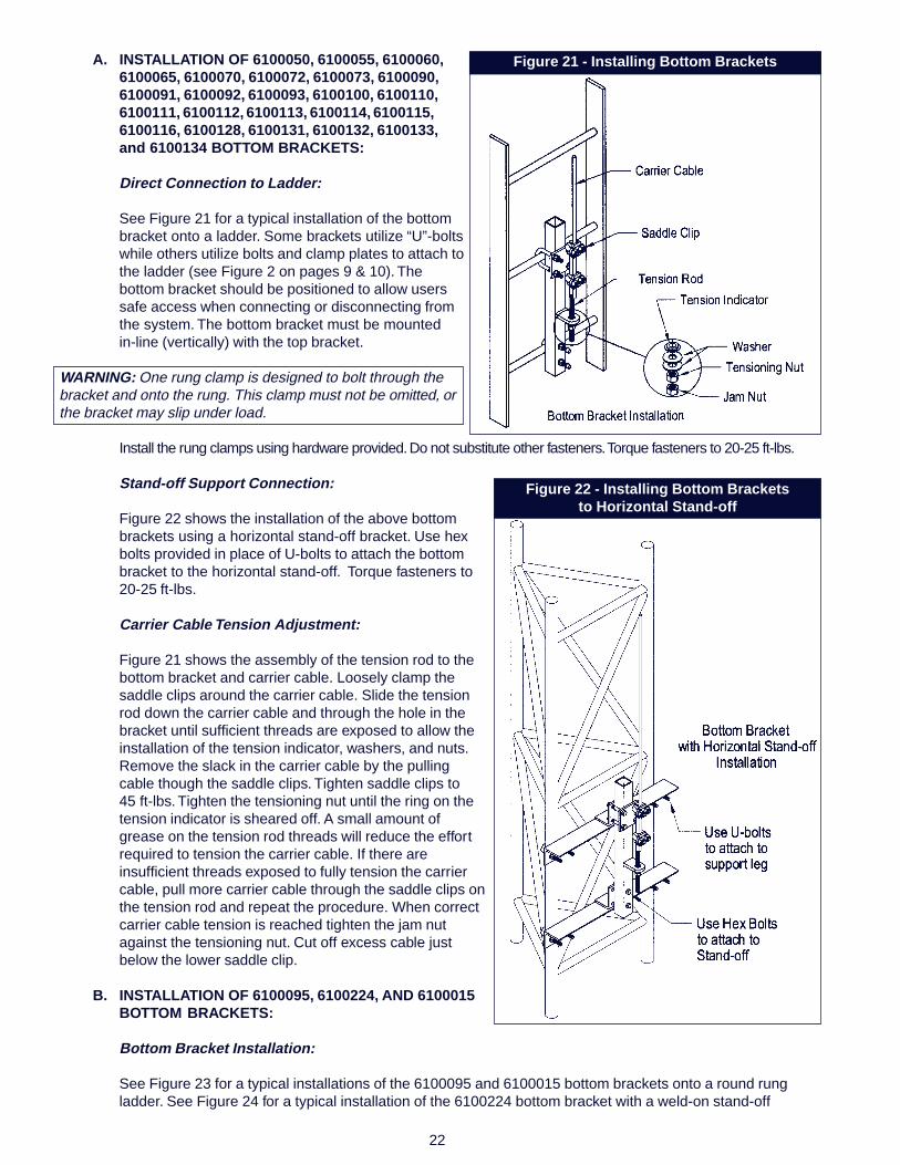
A. INSTALLATION OF 6100050, 6100055, 6100060,6100065, 6100070, 6100072, 6100073, 6100090,6100091, 6100092, 6100093, 6100100, 6100110,6100111, 6100112, 6100113, 6100114, 6100115,6100116, 6100128, 6100131, 6100132, 6100133,and 6100134 BOTTOM BRACKETS:
Direct Connection to Ladder:
See Figure 21 for a typical installation of the bottombracket onto a ladder. Some brackets utilize “U”-boltswhile others utilize bolts and clamp plates to attach tothe ladder (see Figure 2 on pages 9 & 10). Thebottom bracket should be positioned to allow userssafe access when connecting or disconnecting fromthe system. The bottom bracket must be mountedin-line (vertically) with the top bracket.
WARNING: One rung clamp is designed to bolt through thebracket and onto the rung. This clamp must not be omitted, orthe bracket may slip under load.
Install the rung clamps using hardware provided. Do not substitute other fasteners. Torque fasteners to 20-25 ft-lbs.
Stand-off Support Connection:
Figure 22 shows the installation of the above bottombrackets using a horizontal stand-off bracket. Use hexbolts provided in place of U-bolts to attach the bottombracket to the horizontal stand-off. Torque fasteners to20-25 ft-lbs.
Carrier Cable Tension Adjustment:
Figure 21 shows the assembly of the tension rod to thebottom bracket and carrier cable. Loosely clamp thesaddle clips around the carrier cable. Slide the tensionrod down the carrier cable and through the hole in thebracket until sufficient threads are exposed to allow theinstallation of the tension indicator, washers, and nuts.Remove the slack in the carrier cable by the pullingcable though the saddle clips. Tighten saddle clips to45 ft-lbs. Tighten the tensioning nut until the ring on thetension indicator is sheared off. A small amount ofgrease on the tension rod threads will reduce the effortrequired to tension the carrier cable. If there areinsufficient threads exposed to fully tension the carriercable, pull more carrier cable through the saddle clips onthe tension rod and repeat the procedure. When correctcarrier cable tension is reached tighten the jam nutagainst the tensioning nut. Cut off excess cable justbelow the lower saddle clip.
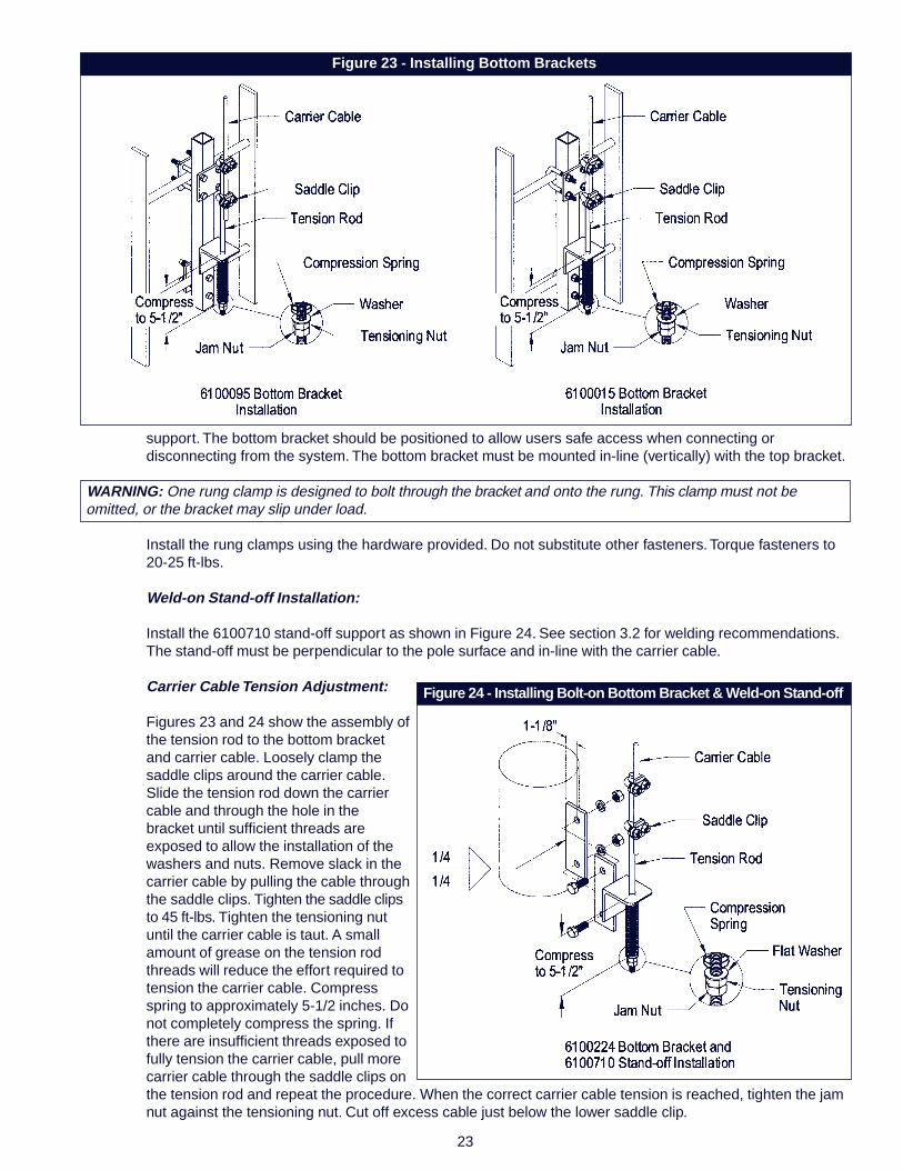
B. INSTALLATION OF 6100095, 6100224, AND 6100015BOTTOM BRACKETS:
Bottom Bracket Installation:
See Figure 23 for a typical installations of the 6100095 and 6100015 bottom brackets onto a round rungladder. See Figure 24 for a typical installation of the 6100224 bottom bracket with a weld-on stand-off
Figure 21 - Installing Bottom Brackets
Figure 22 - Installing Bottom Bracketsto Horizontal Stand-off
23
Figure 24 - Installing Bolt-on Bottom Bracket & Weld-on Stand-off
Figure 23 - Installing Bottom Brackets
support. The bottom bracket should be positioned to allow users safe access when connecting ordisconnecting from the system. The bottom bracket must be mounted in-line (vertically) with the top bracket.
WARNING: One rung clamp is designed to bolt through the bracket and onto the rung. This clamp must not beomitted, or the bracket may slip under load.
Install the rung clamps using the hardware provided. Do not substitute other fasteners. Torque fasteners to20-25 ft-lbs.
Weld-on Stand-off Installation:
Install the 6100710 stand-off support as shown in Figure 24. See section 3.2 for welding recommendations.The stand-off must be perpendicular to the pole surface and in-line with the carrier cable.
Carrier Cable Tension Adjustment:
Figures 23 and 24 show the assembly ofthe tension rod to the bottom bracketand carrier cable. Loosely clamp thesaddle clips around the carrier cable.Slide the tension rod down the carriercable and through the hole in thebracket until sufficient threads areexposed to allow the installation of thewashers and nuts. Remove slack in thecarrier cable by pulling the cable throughthe saddle clips. Tighten the saddle clipsto 45 ft-lbs. Tighten the tensioning nutuntil the carrier cable is taut. A smallamount of grease on the tension rodthreads will reduce the effort required totension the carrier cable. Compressspring to approximately 5-1/2 inches. Donot completely compress the spring. Ifthere are insufficient threads exposed tofully tension the carrier cable, pull morecarrier cable through the saddle clips onthe tension rod and repeat the procedure. When the correct carrier cable tension is reached, tighten the jamnut against the tensioning nut. Cut off excess cable just below the lower saddle clip.

24
C. INSTALLATION OF 6100035 AND6100038 BOLT-ON BOTTOMBRACKETS:
Bottom Bracket Installation:
See Figure 25 for a typical installation ofthe 6100035 and 6100038 bottombrackets. The bottom bracket should bepositioned to allow users safe accesswhen connecting or disconnecting fromthe system. The bottom bracket must bemounted in-line (vertically) with the topbracket. The 6100035 and 6100040bottom brackets are designed to beconnected to the structure using aDBI/SALA or customer supplied stand-off support. Customer supplied stand-offsupports must be capable ofwithstanding the loads specified insection 2.3 and must be compatible withthe LAD-SAF® system.
Weld-on Stand-off Installation:
Install the 6100710 stand-off support as shown in Figure 25. See section 3.2 for welding recommendations.The stand-off must be perpendicular to the pole surface and in-line with the carrier cable.
Angle Leg and Round Leg Stand-off Installation:
See Figure 26 for the installation ofround and angle leg stand-offsupports. Install stand-off supportsusing the hardware provided. Do notsubstitute other fasteners. Torque 3/8inch fasteners to 20-25 ft-lbs. Installbottom bracket to stand-off supportusing 1/2 inch fasteners provided.Torque 1/2 inch fasteners to 40-45 ft-lbs.
Carrier Cable Tension Adjustment:
Figure 25 shows the assembly of thetension rod to the bottom bracket andcarrier cable. Loosely clamp thesaddle clips around the carrier cable.Slide the tension rod down the carriercable and through the hole in thebracket until sufficient threads areexposed to allow the installation ofthe tension indicator, washers, andnuts. Remove slack in the carriercable by pulling the cable though the saddle clips. Tighten saddle clips to 45 ft-lbs. Tighten the tensioning nutuntil the ring on the tension indicator is sheared off. A small amount of grease on the tension rod threads willreduce the effort required to tension the carrier cable. If there are insufficient threads exposed to fully tensionthe carrier cable, pull more carrier cable through the saddle clips on the tension rod and repeat theprocedure. When the correct carrier cable tension is reached, tighten the jam nut against the tensioning nut.Cut off excess cable just below the lower saddle clip.
Figure 25 - Installing Bottom Brackets and Weld-on Stand-off
Figure 26 - Installing Angle Leg & Round Leg Stand-offs
25
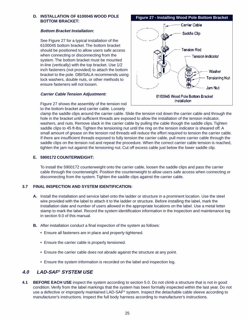
Figure 27 - Installing Wood Pole Bottom BracketD. INSTALLATION OF 6100045 WOOD POLEBOTTOM BRACKET:
Bottom Bracket Installation:
See Figure 27 for a typical installation of the6100045 bottom bracket. The bottom bracketshould be positioned to allow users safe accesswhen connecting or disconnecting from thesystem. The bottom bracket must be mountedin-line (vertically) with the top bracket. Use 1/2inch fasteners (not provided) to attach the bottombracket to the pole. DBI/SALA recommends usinglock washers, double nuts, or other methods toensure fasteners will not loosen.
Carrier Cable Tension Adjustment:
Figure 27 shows the assembly of the tension rodto the bottom bracket and carrier cable. Looselyclamp the saddle clips around the carrier cable. Slide the tension rod down the carrier cable and through thehole in the bracket until sufficient threads are exposed to allow the installation of the tension indicator,washers, and nuts. Remove slack in the carrier cable by pulling the cable though the saddle clips. Tightensaddle clips to 45 ft-lbs. Tighten the tensioning nut until the ring on the tension indicator is sheared off. Asmall amount of grease on the tension rod threads will reduce the effort required to tension the carrier cable.If there are insufficient threads exposed to fully tension the carrier cable, pull more carrier cable through thesaddle clips on the tension rod and repeat the procedure. When the correct carrier cable tension is reached,tighten the jam nut against the tensioning nut. Cut off excess cable just below the lower saddle clip.
E. 5900172 COUNTERWEIGHT:
To install the 5900172 counterweight onto the carrier cable, loosen the saddle clips and pass the carriercable through the counterweight. Position the counterweight to allow users safe access when connecting ordisconnecting from the system. Tighten the saddle clips against the carrier cable.
3.7 FINAL INSPECTION AND SYSTEM IDENTIFICATION:
A. Install the installation and service label onto the ladder or structure in a prominent location. Use the steelwire provided with the label to attach it to the ladder or structure. Before installing the label, mark theinstallation date and number of users allowed in the appropriate locations on the label. Use a metal letterstamp to mark the label. Record the system identification information in the inspection and maintenance login section 9.0 of this manual.
B. After installation conduct a final inspection of the system as follows:
• Ensure all fasteners are in place and properly tightened.
• Ensure the carrier cable is properly tensioned.
• Ensure the carrier cable does not abrade against the structure at any point.
• Ensure the system information is recorded on the label and inspection log.
4.0 LAD-SAF® SYSTEM USE
4.1 BEFORE EACH USE inspect the system according to section 5.0. Do not climb a structure that is not in goodcondition. Verify from the label markings that the system has been formally inspected within the last year. Do notuse a defective or improperly maintained LAD-SAF® system. Inspect the detachable cable sleeve according tomanufacturer’s instructions. Inspect the full body harness according to manufacturer’s instructions.
26
4.2 PLAN your use of the LAD-SAF® system before starting work. Consider all factors that will affect your safetybefore starting your work. The following list gives some important points to consider when planning your work:
• Ensure the system is rated for the number of users required on the system before use.
• Consider hazards associated with connecting and disconnecting from the system. Ensure adequateanchor points, landing platforms, or other means are available at connection and disconnection points toallow safe transitions to and from the system.
• Be aware of hazards in the work area that could cause injury to the user or damage to the system, suchas; high heat, electrical hazards, chemical hazards, or moving machinery.
• Use caution when climbing. Avoid carrying tools or equipment that do not allow your hands to be free forclimbing. Ensure items carried are secure to avoid dropping them on climbers below. Climb within yourability. Long climbs may require several rest stops during ascent or descent to avoid exhaustion. Avoidclimbing in high winds or severe weather whenever possible.
• If a fall occurs the user (employer) must have a rescue plan and the ability to implement it.
4.3 TRAINING: It is the responsibility of the user and purchaser of this equipment to assure they are familiar with theinstructions, operating characteristics, application limits, and the consequences of improper use of thisequipment. Users and purchasers of this equipment must be trained in the correct care and use of thisequipment. Contact DBI/SALA for additional training guidelines.
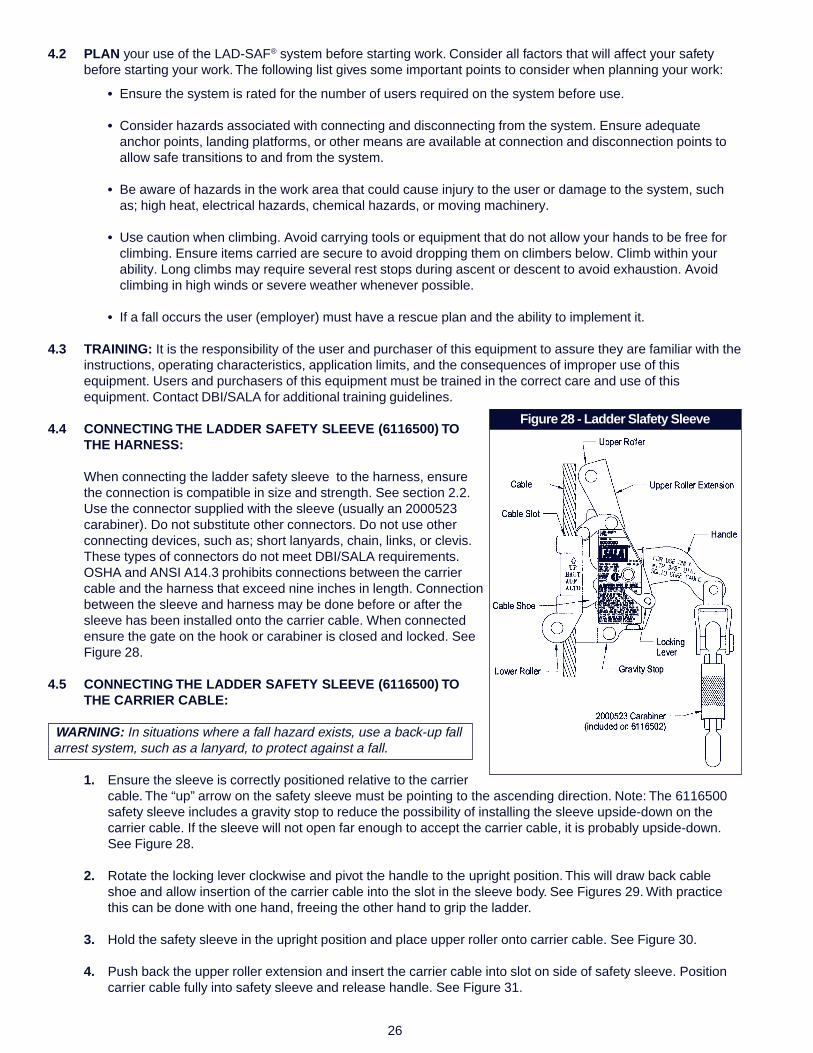
4.4 CONNECTING THE LADDER SAFETY SLEEVE (6116500) TOTHE HARNESS:
When connecting the ladder safety sleeve to the harness, ensurethe connection is compatible in size and strength. See section 2.2.Use the connector supplied with the sleeve (usually an 2000523carabiner). Do not substitute other connectors. Do not use otherconnecting devices, such as; short lanyards, chain, links, or clevis.These types of connectors do not meet DBI/SALA requirements.OSHA and ANSI A14.3 prohibits connections between the carriercable and the harness that exceed nine inches in length. Connectionbetween the sleeve and harness may be done before or after thesleeve has been installed onto the carrier cable. When connectedensure the gate on the hook or carabiner is closed and locked. SeeFigure 28.
4.5 CONNECTING THE LADDER SAFETY SLEEVE (6116500) TOTHE CARRIER CABLE:
WARNING: In situations where a fall hazard exists, use a back-up fallarrest system, such as a lanyard, to protect against a fall.
1. Ensure the sleeve is correctly positioned relative to the carriercable. The “up” arrow on the safety sleeve must be pointing to the ascending direction. Note: The 6116500safety sleeve includes a gravity stop to reduce the possibility of installing the sleeve upside-down on thecarrier cable. If the sleeve will not open far enough to accept the carrier cable, it is probably upside-down.See Figure 28.
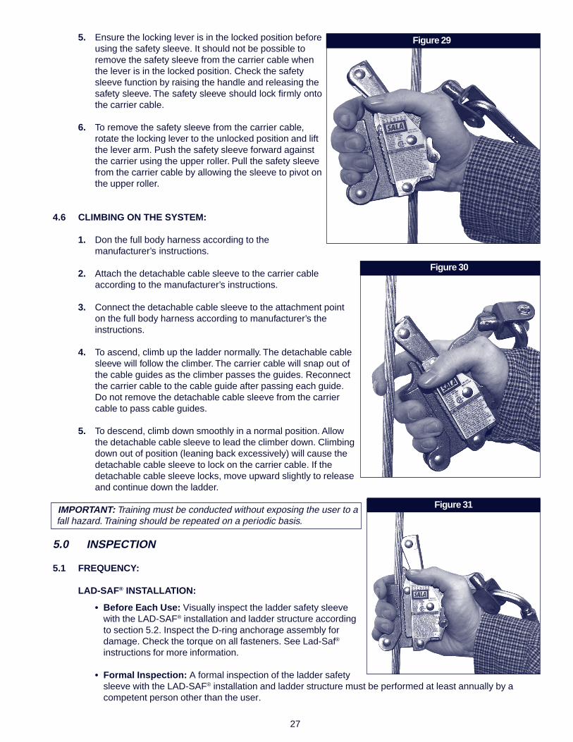
2. Rotate the locking lever clockwise and pivot the handle to the upright position. This will draw back cableshoe and allow insertion of the carrier cable into the slot in the sleeve body. See Figures 29. With practicethis can be done with one hand, freeing the other hand to grip the ladder.
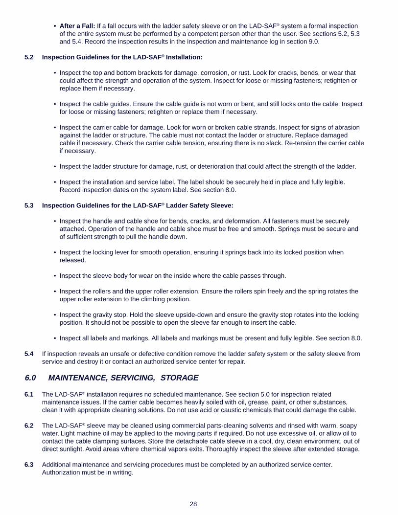
3. Hold the safety sleeve in the upright position and place upper roller onto carrier cable. See Figure 30.
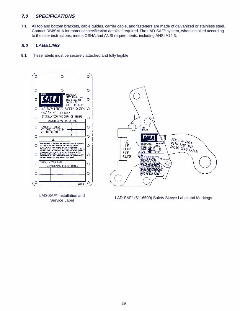
4. Push back the upper roller extension and insert the carrier cable into slot on side of safety sleeve. Positioncarrier cable fully into safety sleeve and release handle. See Figure 31.
Figure 28 - Ladder Slafety Sleeve
27
Figure 29
Figure 30
Figure 31
5. Ensure the locking lever is in the locked position beforeusing the safety sleeve. It should not be possible toremove the safety sleeve from the carrier cable whenthe lever is in the locked position. Check the safetysleeve function by raising the handle and releasing thesafety sleeve. The safety sleeve should lock firmly ontothe carrier cable.
6. To remove the safety sleeve from the carrier cable,rotate the locking lever to the unlocked position and liftthe lever arm. Push the safety sleeve forward againstthe carrier using the upper roller. Pull the safety sleevefrom the carrier cable by allowing the sleeve to pivot onthe upper roller.
4.6 CLIMBING ON THE SYSTEM:
1. Don the full body harness according to themanufacturer’s instructions.
2. Attach the detachable cable sleeve to the carrier cableaccording to the manufacturer’s instructions.
3. Connect the detachable cable sleeve to the attachment pointon the full body harness according to manufacturer’s theinstructions.
4. To ascend, climb up the ladder normally. The detachable cablesleeve will follow the climber. The carrier cable will snap out ofthe cable guides as the climber passes the guides. Reconnectthe carrier cable to the cable guide after passing each guide.Do not remove the detachable cable sleeve from the carriercable to pass cable guides.
5. To descend, climb down smoothly in a normal position. Allowthe detachable cable sleeve to lead the climber down. Climbingdown out of position (leaning back excessively) will cause thedetachable cable sleeve to lock on the carrier cable. If thedetachable cable sleeve locks, move upward slightly to releaseand continue down the ladder.
IMPORTANT: Training must be conducted without exposing the user to afall hazard. Training should be repeated on a periodic basis.
5.0 INSPECTION
5.1 FREQUENCY:
LAD-SAF® INSTALLATION:
• Before Each Use: Visually inspect the ladder safety sleevewith the LAD-SAF® installation and ladder structure accordingto section 5.2. Inspect the D-ring anchorage assembly fordamage. Check the torque on all fasteners. See Lad-Saf®
instructions for more information.
• Formal Inspection: A formal inspection of the ladder safetysleeve with the LAD-SAF® installation and ladder structure must be performed at least annually by acompetent person other than the user.
28
• After a Fall: If a fall occurs with the ladder safety sleeve or on the LAD-SAF® system a formal inspectionof the entire system must be performed by a competent person other than the user. See sections 5.2, 5.3and 5.4. Record the inspection results in the inspection and maintenance log in section 9.0.
5.2 Inspection Guidelines for the LAD-SAF® Installation:
• Inspect the top and bottom brackets for damage, corrosion, or rust. Look for cracks, bends, or wear thatcould affect the strength and operation of the system. Inspect for loose or missing fasteners; retighten orreplace them if necessary.
• Inspect the cable guides. Ensure the cable guide is not worn or bent, and still locks onto the cable. Inspectfor loose or missing fasteners; retighten or replace them if necessary.
• Inspect the carrier cable for damage. Look for worn or broken cable strands. Inspect for signs of abrasionagainst the ladder or structure. The cable must not contact the ladder or structure. Replace damagedcable if necessary. Check the carrier cable tension, ensuring there is no slack. Re-tension the carrier cableif necessary.
• Inspect the ladder structure for damage, rust, or deterioration that could affect the strength of the ladder.
• Inspect the installation and service label. The label should be securely held in place and fully legible.Record inspection dates on the system label. See section 8.0.
5.3 Inspection Guidelines for the LAD-SAF® Ladder Safety Sleeve:
• Inspect the handle and cable shoe for bends, cracks, and deformation. All fasteners must be securelyattached. Operation of the handle and cable shoe must be free and smooth. Springs must be secure andof sufficient strength to pull the handle down.
• Inspect the locking lever for smooth operation, ensuring it springs back into its locked position whenreleased.
• Inspect the sleeve body for wear on the inside where the cable passes through.
• Inspect the rollers and the upper roller extension. Ensure the rollers spin freely and the spring rotates theupper roller extension to the climbing position.
• Inspect the gravity stop. Hold the sleeve upside-down and ensure the gravity stop rotates into the lockingposition. It should not be possible to open the sleeve far enough to insert the cable.
• Inspect all labels and markings. All labels and markings must be present and fully legible. See section 8.0.
5.4 If inspection reveals an unsafe or defective condition remove the ladder safety system or the safety sleeve fromservice and destroy it or contact an authorized service center for repair.
6.0 MAINTENANCE, SERVICING, STORAGE
6.1 The LAD-SAF® installation requires no scheduled maintenance. See section 5.0 for inspection relatedmaintenance issues. If the carrier cable becomes heavily soiled with oil, grease, paint, or other substances,clean it with appropriate cleaning solutions. Do not use acid or caustic chemicals that could damage the cable.
6.2 The LAD-SAF® sleeve may be cleaned using commercial parts-cleaning solvents and rinsed with warm, soapywater. Light machine oil may be applied to the moving parts if required. Do not use excessive oil, or allow oil tocontact the cable clamping surfaces. Store the detachable cable sleeve in a cool, dry, clean environment, out ofdirect sunlight. Avoid areas where chemical vapors exits. Thoroughly inspect the sleeve after extended storage.
6.3 Additional maintenance and servicing procedures must be completed by an authorized service center.Authorization must be in writing.
29
7.0 SPECIFICATIONS
7.1 All top and bottom brackets, cable guides, carrier cable, and fasteners are made of galvanized or stainless steel.Contact DBI/SALA for material specification details if required. The LAD-SAF® system, when installed accordingto the user instructions, meets OSHA and ANSI requirements, including ANSI A14.3.
8.0 LABELING
8.1 These labels must be securely attached and fully legible:
LAD-SAF® Installation andService Label
LAD-SAF® (6116500) Safety Sleeve Label and Markings

ETADNOITCEPSNI SMETINOITCEPSNIDETON
NOITCAEVITCERROC ECNANETNIAMDEMROFREP
:yBdevorppA
:yBdevorppA
:yBdevorppA
:yBdevorppA
:yBdevorppA
:yBdevorppA
:yBdevorppA
:yBdevorppA
:yBdevorppA
:yBdevorppA
:yBdevorppA
:yBdevorppA
9.0 INSPECTION AND MAINTENANCE LOG
DATE OF MANUFACTURE: _______________________________________________________________________
MODEL NUMBER: ______________________________________________________________________________
DATE PURCHASED: ________________________________________________________________________________
30


USA Canada3965 Pepin Avenue 260 Export BoulevardRed Wing, MN 55066-1837 Mississauga, Ontario L5S 1Y9Toll Free: 800-328-6146 Toll Free: 800-387-7484Phone: (651) 388-8282 Phone: (905) 795-9333Fax: (651) 388-5065 Fax: (905) 795-8777www.salagroup.com
WARRANTY
Equipment offered by DBI/SALA are warranted against factory defects inworkmanship and materials for a period of two year from the date of installation oruse by the owner, provided that this period shall not exceed two years from the dateof shipment. Upon notice in writing, DBI/SALA will promptly repair or replace alldefective items. DBI/SALA reserves the right to elect to have any defective itemreturned to its plant for inspection before making a repair or replacement. Thiswarranty does not cover equipment damages resulting from abuse, damage in transit,or other damage beyond the control of DBI/SALA. This warranty applies only tooriginal purchaser and is the only one applicable to our products and is in lieu of allother warranties expressed or implied.
Form: 5902228Rev: H
I S O
9 0 0 1
Certificate No. FM 39709