Embed Size (px)
Citation preview
Experience In Motion
USER INSTRUCTIONS
Installationand Operation
Flowserve Snap-OnDiagnostic Software Module
FCD VLENIM0113-00 – 11/05
Snap-On Diagnostic Software Module FCD VLENIM0113-00 – 11/05
�
1Introduction
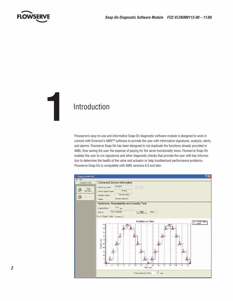
Flowserve’s easy-to-use and informative Snap-On diagnostic software module is designed to work in concert with Emerson’s AMS™ software to provide the user with informative signatures, analysis, alerts, and alarms. Flowserve Snap-On has been designed to not duplicate the functions already provided in AMS, thus saving the user the expense of paying for the same functionality twice. Flowserve Snap-On enables the user to run signatures and other diagnostic checks that provide the user with key informa-tion to determine the health of the valve and actuator or help troubleshoot performance problems. Flowserve Snap-On is compatible with AMS versions 6.0 and later.
3
Snap-On Diagnostic Software Module FCD VLENIM0113-00 – 11/05
flowserve.com
2Getting Started
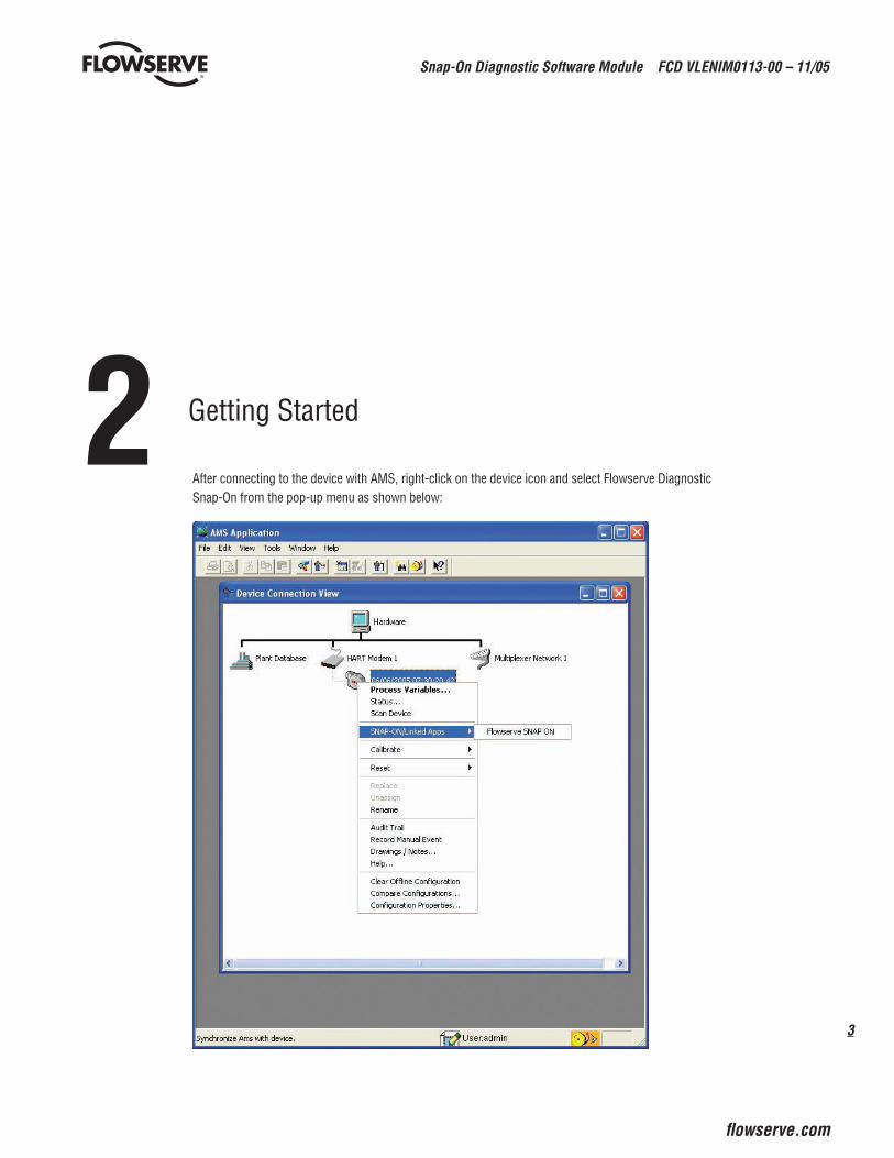
After connecting to the device with AMS, right-click on the device icon and select Flowserve Diagnostic Snap-On from the pop-up menu as shown below:
Snap-On Diagnostic Software Module FCD VLENIM0113-00 – 11/05
�
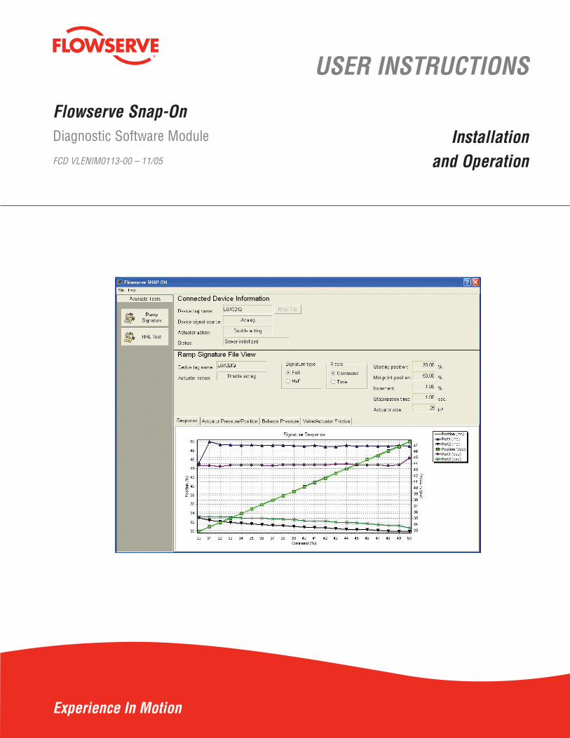
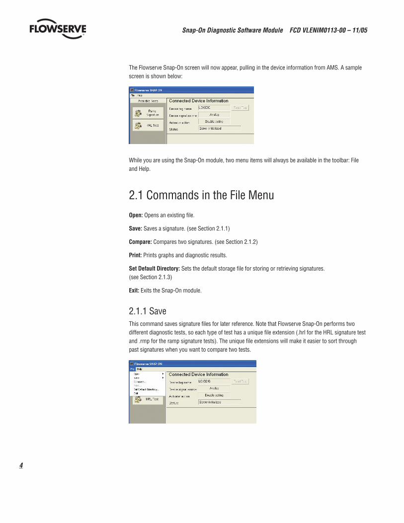
The Flowserve Snap-On screen will now appear, pulling in the device information from AMS. A sample screen is shown below:
While you are using the Snap-On module, two menu items will always be available in the toolbar: File and Help.
2.1 Commands in the File MenuOpen: Opens an existing file.
Save: Saves a signature. (see Section 2.1.1)
Compare: Compares two signatures. (see Section 2.1.2)
Print: Prints graphs and diagnostic results.
SetDefaultDirectory: Sets the default storage file for storing or retrieving signatures. (see Section 2.1.3)
Exit: Exits the Snap-On module.
2.1.1 SaveThis command saves signature files for later reference. Note that Flowserve Snap-On performs two different diagnostic tests, so each type of test has a unique file extension (.hrl for the HRL signature test and .rmp for the ramp signature tests). The unique file extensions will make it easier to sort through past signatures when you want to compare two tests.
5
Snap-On Diagnostic Software Module FCD VLENIM0113-00 – 11/05
flowserve.com
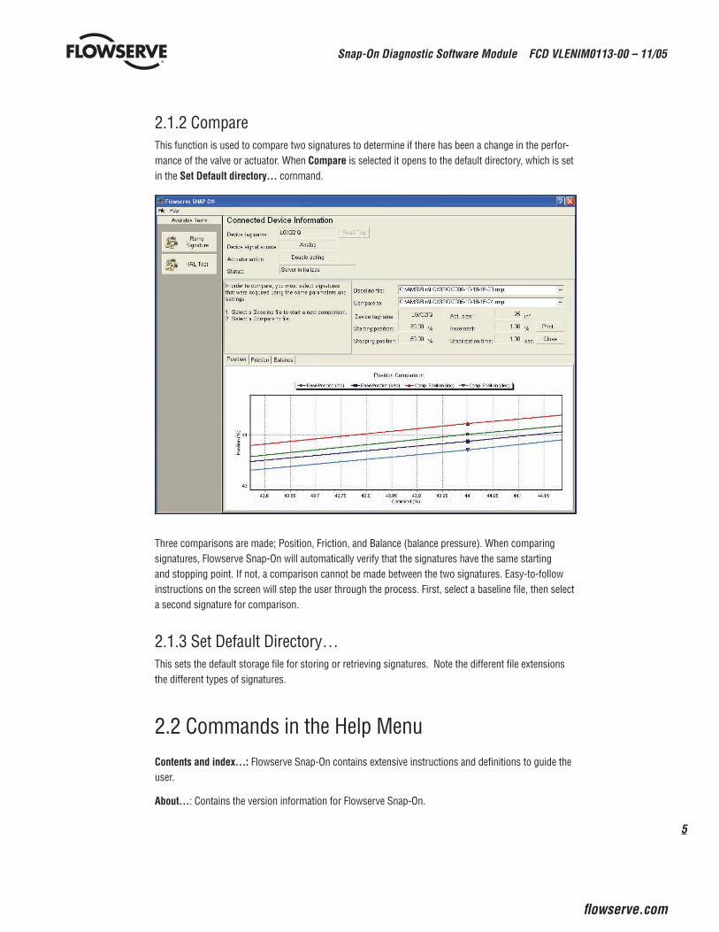
2.1.2 CompareThis function is used to compare two signatures to determine if there has been a change in the perfor-mance of the valve or actuator. When Compare is selected it opens to the default directory, which is set in the SetDefaultdirectory…command.
Three comparisons are made; Position, Friction, and Balance (balance pressure). When comparing signatures, Flowserve Snap-On will automatically verify that the signatures have the same starting and stopping point. If not, a comparison cannot be made between the two signatures. Easy-to-follow instructions on the screen will step the user through the process. First, select a baseline file, then select a second signature for comparison.
2.1.3 Set Default Directory…This sets the default storage file for storing or retrieving signatures. Note the different file extensions the different types of signatures.
2.2 Commands in the Help MenuContentsandindex…:Flowserve Snap-On contains extensive instructions and definitions to guide the user.
About…: Contains the version information for Flowserve Snap-On.
Snap-On Diagnostic Software Module FCD VLENIM0113-00 – 11/05
�
3Connected Device Information Pane
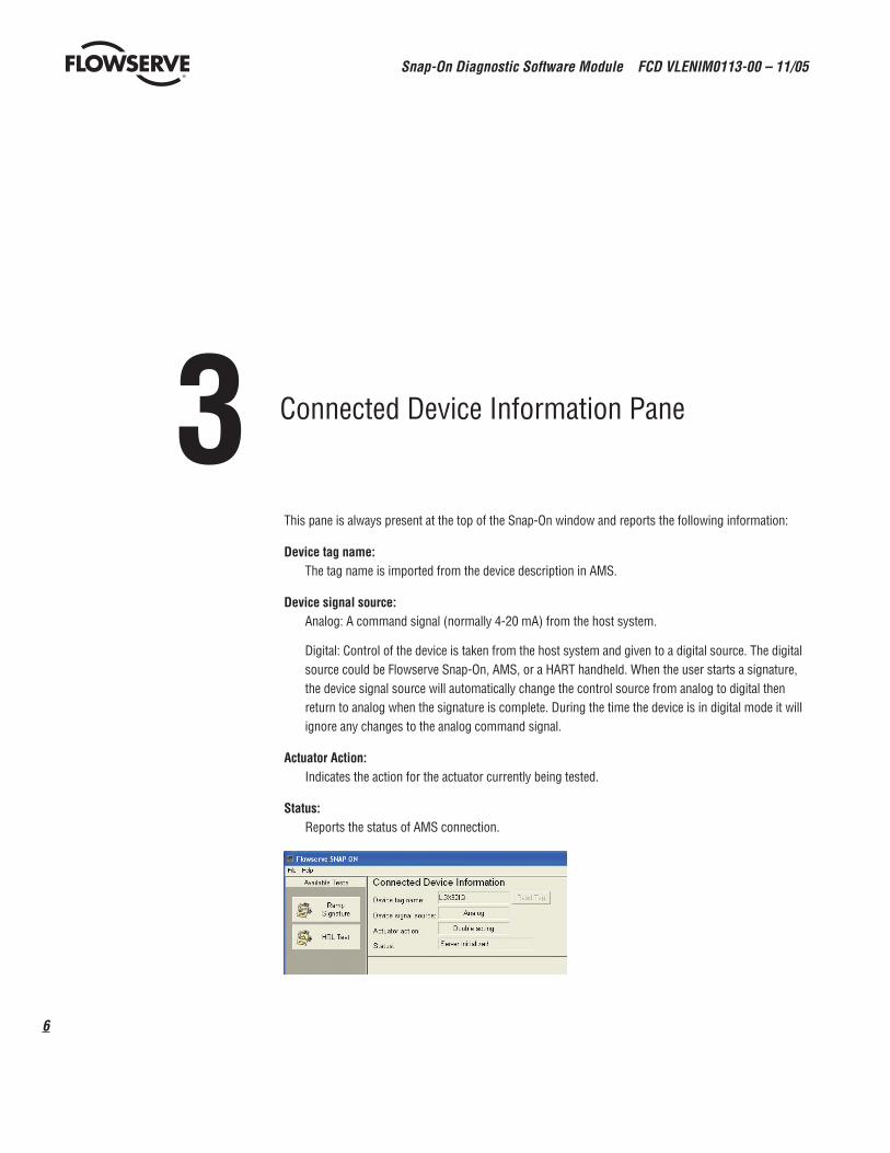
This pane is always present at the top of the Snap-On window and reports the following information:
Devicetagname:The tag name is imported from the device description in AMS.
Devicesignalsource:Analog: A command signal (normally 4-20 mA) from the host system.
Digital: Control of the device is taken from the host system and given to a digital source. The digital source could be Flowserve Snap-On, AMS, or a HART handheld. When the user starts a signature, the device signal source will automatically change the control source from analog to digital then return to analog when the signature is complete. During the time the device is in digital mode it will ignore any changes to the analog command signal.
ActuatorAction:Indicates the action for the actuator currently being tested.
Status:Reports the status of AMS connection.
�
Snap-On Diagnostic Software Module FCD VLENIM0113-00 – 11/05
flowserve.com
4Tests
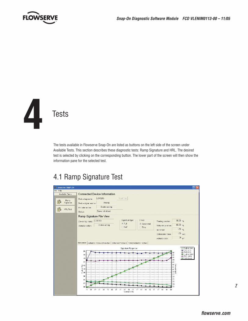
The tests available in Flowserve Snap-On are listed as buttons on the left side of the screen under Available Tests. This section describes these diagnostic tests: Ramp Signature and HRL. The desired test is selected by clicking on the corresponding button. The lower part of the screen will then show the information pane for the selected test.
4.1 Ramp Signature Test
Snap-On Diagnostic Software Module FCD VLENIM0113-00 – 11/05
�
The following items are always visible at the top part of the Ramp Signature test pane:
Elapsedtime:Indicates the total time required to acquire all data needed to plot the signature.
Status:Indicates the current status or progress of the test. The statuses are as follows:
Ready- The system is ready to start the test.
Stabilizing- Before starting a signature it takes a few seconds to “stabilize” the actuator.
Acquiring Data…- After Flowserve Snap-On has determined the valve is stable; it will begin the ramp test. The status will report “Acquiring Data…” from the start to the finish of the change in command signal.
Completed- The test and calculations have been completed.
Signaturetype:Bidirectional- A round-trip ramp test from a Starting position to a turn-around point (Mid-point) then back to the Starting position.
Unidirectional- A one-way ramp test from a Starting position to a Stopping position only.
X-axis:The X-axis can be switched between Command and Time.
Startingposition:Sets a user-selectable starting point for the ramp test, in % of full stroke.
Mid-pointorStoppingposition:For a Unidirectional test, this sets a user-selectable ending point. For a Bidirectional test, this sets a user-selectable turn-around point. The label will change according to which Signature type is selected.
Increment:The step sizes for the ramp signature test, given in %.
Stabilizationtime:Indicates the time between incremental changes.
Actuatorsize:The correct actuator size must be entered here for correct friction calculations. The default value is 25 but can be changed by typing in a different value (50, 100, 200, etc.)
Startbutton:Clicking this button starts the test. When Start is clicked, the following warning box appears:
“Setting Device in Digital Mode. The device will not respond to DCS or analog controller until test completes. Continue?”
Click Continue to begin the test or Cancelto return to the test pane.
�
Snap-On Diagnostic Software Module FCD VLENIM0113-00 – 11/05
flowserve.com
At the conclusion of the ramp signature test, the following prompt will appear: “Save current test?” to which the user can choose Yes or No. If the user selects Yes, a save dialog will appear. The default directory is the one selected using the SetDefaultDirectory… command under the File menu. The naming format of the file is structured so that the tests will be stored in chronological order: YYYY-MM-DD-HR-MM.
Example: 2005-09-07-08-25 is 2005-September, 07 at 8:25 AM.
Abortbutton:This button aborts the test and returns the device to analog mode. It becomes active once the test is started.
The RampSignaturetest has four tabs for a double-acting actuator:
NOtE: Single-acting actuators only have the Response tab which shows position vs. command.
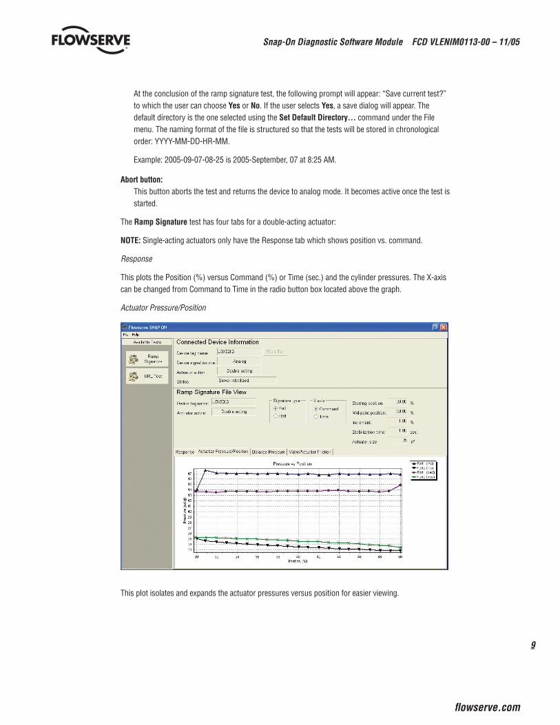
Response
This plots the Position (%) versus Command (%) or Time (sec.) and the cylinder pressures. The X-axis can be changed from Command to Time in the radio button box located above the graph.
Actuator Pressure/Position
This plot isolates and expands the actuator pressures versus position for easier viewing.
Snap-On Diagnostic Software Module FCD VLENIM0113-00 – 11/05
10
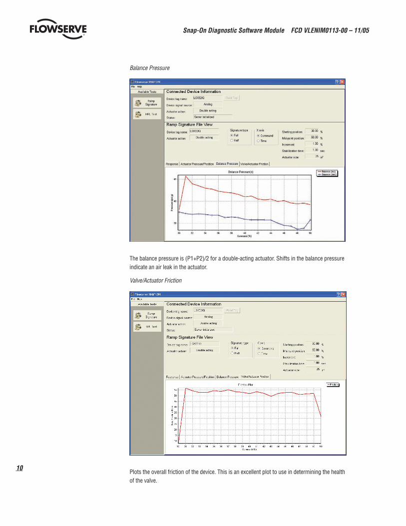
Balance Pressure
The balance pressure is (P1+P2)/2 for a double-acting actuator. Shifts in the balance pressure indicate an air leak in the actuator.
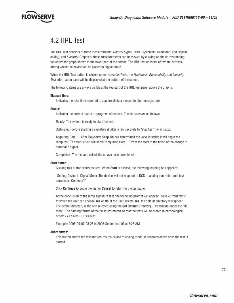
Valve/Actuator Friction
Plots the overall friction of the device. This is an excellent plot to use in determining the health of the valve.
11
Snap-On Diagnostic Software Module FCD VLENIM0113-00 – 11/05
flowserve.com
4.2 HRL TestThe HRL Test consists of three measurements: Control Signal, HDR (Hysteresis, Deadband, and Repeat-ability), and Linearity. Graphs of these measurements can be viewed by clicking on the corresponding tab above the graph shown in the lower part of the screen. The HRL test consists of two full strokes, during which the device will be placed in digital mode.
When the HRL Test button is clicked under Available Tests, the Hysteresis, Repeatability and Linearity Test information pane will be displayed at the bottom of the screen.
The following items are always visible at the top part of the HRL test pane, above the graphs:
Elapsedtime:Indicates the total time required to acquire all data needed to plot the signature.
Status:Indicates the current status or progress of the test. The statuses are as follows:
Ready- The system is ready to start the test.
Stabilizing- Before starting a signature it takes a few seconds to “stabilize” the actuator.
Acquiring Data…- After Flowserve Snap-On has determined the valve is stable it will begin the ramp test. The status field will show “Acquiring Data…” from the start to the finish of the change in command signal.
Completed- The test and calculations have been completed.
Startbutton:Clicking this button starts the test. When Start is clicked, the following warning box appears:
“Setting Device in Digital Mode. The device will not respond to DCS or analog controller until test completes. Continue?”
Click Continue to begin the test or Cancel to return to the test pane.
At the conclusion of the ramp signature test, the following prompt will appear: “Save current test?” to which the user can choose Yes or No. If the user selects Yes, the default directory will appear. The default directory is the one selected using the SetDefaultDirectory… command under the File menu. The naming format of the file is structured so that the tests will be stored in chronological order: YYYY-MM-DD-HR-MM.
Example: 2005-09-07-08-25 is 2005-September, 07 at 8:25 AM.
Abortbutton:This button aborts the test and returns the device to analog mode. It becomes active once the test is started.
Snap-On Diagnostic Software Module FCD VLENIM0113-00 – 11/05
1�
Tabs for the different measurements appear directly above the graph, clicking the desired tab with show the plot for that measurement.
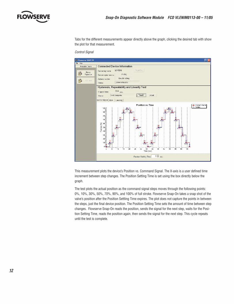
Control Signal
This measurement plots the device’s Position vs. Command Signal. The X-axis is a user defined time increment between step changes. The Position Setting Time is set using the box directly below the graph.
The test plots the actual position as the command signal steps moves through the following points: 0%, 10%, 30%, 50%, 70%, 90%, and 100% of full stroke. Flowserve Snap-On takes a snap shot of the valve’s position after the Position Settling Time expires. The plot does not capture the points in between the steps, just the final device position. The Position Setting Time sets the amount of time between step changes. Flowserve Snap-On reads the position, sends the signal for the next step, waits for the Posi-tion Setting Time, reads the position again, then sends the signal for the next step. This cycle repeats until the test is complete.
13
Snap-On Diagnostic Software Module FCD VLENIM0113-00 – 11/05
flowserve.com
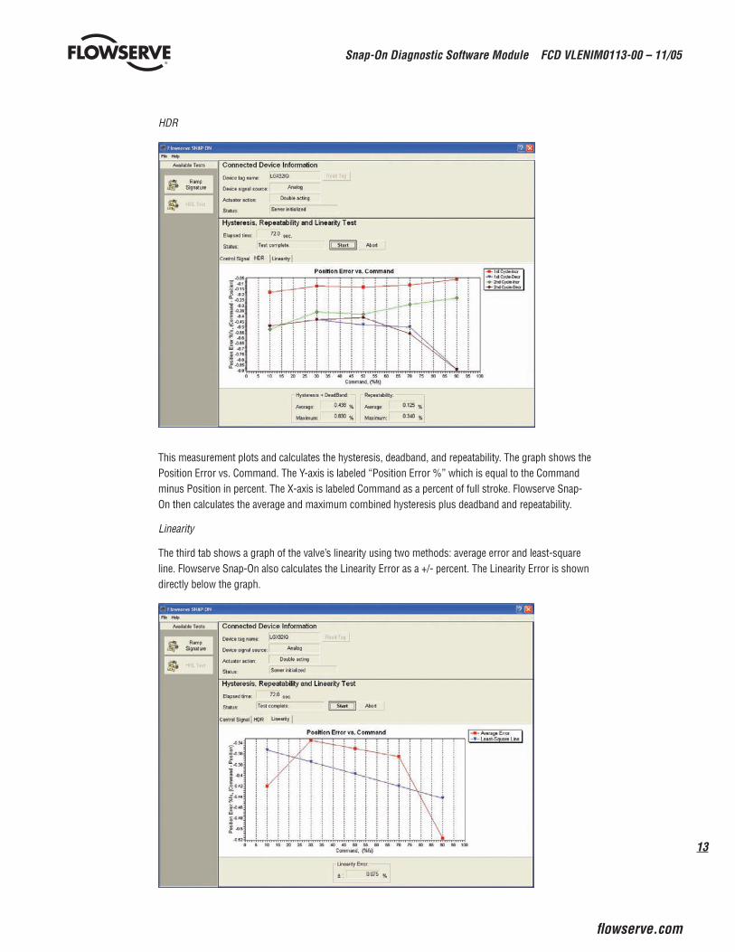
HDR
This measurement plots and calculates the hysteresis, deadband, and repeatability. The graph shows the Position Error vs. Command. The Y-axis is labeled “Position Error %” which is equal to the Command minus Position in percent. The X-axis is labeled Command as a percent of full stroke. Flowserve Snap-On then calculates the average and maximum combined hysteresis plus deadband and repeatability.
Linearity
The third tab shows a graph of the valve’s linearity using two methods: average error and least-square line. Flowserve Snap-On also calculates the Linearity Error as a +/- percent. The Linearity Error is shown directly below the graph.
Snap-On Diagnostic Software Module FCD VLENIM0113-00 – 11/05
1�
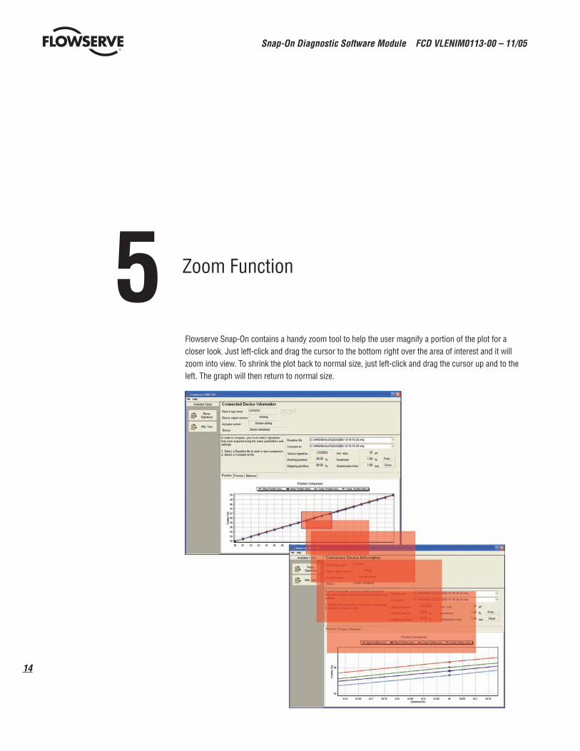
5Zoom Function
Flowserve Snap-On contains a handy zoom tool to help the user magnify a portion of the plot for a closer look. Just left-click and drag the cursor to the bottom right over the area of interest and it will zoom into view. To shrink the plot back to normal size, just left-click and drag the cursor up and to the left. The graph will then return to normal size.
15
Snap-On Diagnostic Software Module FCD VLENIM0113-00 – 11/05
flowserve.com
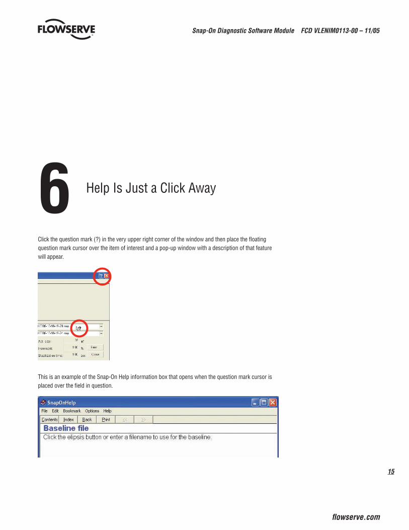
6Help Is Just a Click Away
Click the question mark (?) in the very upper right corner of the window and then place the floating question mark cursor over the item of interest and a pop-up window with a description of that feature will appear.
This is an example of the Snap-On Help information box that opens when the question mark cursor is placed over the field in question.
flowserve.com
To find your local Flowserve representative:
For more information about Flowserve Corporation, visit www.flowserve.com or call USA 1 800 225 6989
FCD VLENIM0113-00 Printed in USA.
Flowserve Corporation has established industry leadership in the design and manufacture of its products. When properly selected, this Flowserve product is designed to perform its intended function safely during its useful life. However, the purchaser or user of Flowserve products should be aware that Flowserve products might be used in numerous applications under a wide variety of industrial service conditions. Although Flowserve can (and often does) provide general guidelines, it cannot provide specific data and warnings for all possible applications. The pur-chaser/user must therefore assume the ultimate responsibility for the proper sizing and selection, installation, operation, and maintenance of Flowserve products. The purchaser/user should read and understand the Installation Operation Maintenance (IOM) instructions included with the product, and train its employees and contractors in the safe use of Flowserve products in connection with the specific application.
While the information and specifications contained in this literature are believed to be accurate, they are supplied for informative purposes only and should not be considered certified or as a guarantee of satisfactory results by reliance thereon. Nothing contained herein is to be construed as a warranty or guarantee, express or implied, regarding any matter with respect to this product. Because Flowserve is continually improving and upgrading its product design, the specifications, dimensions and information contained herein are subject to change without notice. Should any question arise concerning these provisions, the purchaser/user should contact Flowserve Corporation at any one of its worldwide operations or offices.
© 2005 Flowserve Corporation, Irving, Texas, USA. Flowserve is a registered trademark of Flowserve Corporation.
UnitedStatesFlowserve Corp.Flow ControlValtek Control Products1350 N. Mt. Springs ParkwaySpringville, UT 84663 USATelephone: 1 801 489 8611Fax: 1 801 489 3719
SwedenFlowserve PMV Palmstierna International AB Korta Gatan 9 171 54 Solna Sweden Telephone: +46 8 555 10 600 Fax: +46 8 555 10 601