Embed Size (px)
Citation preview

Part Number: 31010TFT
PID Module
User Manual
Issue Draft D
Date 2015-09-28
HUAWEI TECHNOLOGIES CO., LTD.

Issue Draft D (2015-09-28) Huawei Proprietary and Confidential
Copyright © Huawei Technologies Co., Ltd.
i
Copyright © Huawei Technologies Co., Ltd. 2015. All rights reserved.
No part of this document may be reproduced or transmitted in any form or by any means without prior
written consent of Huawei Technologies Co., Ltd.
Trademarks and Permissions
and other Huawei trademarks are trademarks of Huawei Technologies Co., Ltd.
All other trademarks and trade names mentioned in this document are the property of their respective
holders.
Notice
The purchased products, services and features are stipulated by the contract made between Huawei and
the customer. All or part of the products, services and features described in this document may not be
within the purchase scope or the usage scope. Unless otherwise specified in the contract, all statements,
information, and recommendations in this document are provided "AS IS" without warranties, guarantees or
representations of any kind, either express or implied.
The information in this document is subject to change without notice. Every effort has been made in the
preparation of this document to ensure accuracy of the contents, but all statements, information, and
recommendations in this document do not constitute a warranty of any kind, express or implied.
Huawei Technologies Co., Ltd.
Address: Huawei Industrial Base
Bantian, Longgang
Shenzhen 518129
People's Republic of China
Website: http://www.huawei.com
Email: [email protected]

PID Module
User Manual About This Document
Issue Draft D (2015-09-28) Huawei Proprietary and Confidential
Copyright © Huawei Technologies Co., Ltd.
ii
About This Document
Purpose
This document describes the PID installation, electrical connections, maintenance, and
troubleshooting. Readers should be familiar with the PID features, functions, and safety
precautions provided in this document before installing and operating the PID.
For details about how to install the PID and perform electrical connections when installing the
PID inside a Huawei communications cabinet, see the SUN2000 Communications Cabinet
User Manual. For other installation scenarios, see the descriptions in this manual.
Keep the hard copy of this document in good condition for future reference. You can also
download the latest manual from http://support.huawei.com.
Intended Audience
This document is intended for photovoltaic (PV) power station personnel and qualified
electrical technicians.
Symbol Conventions
The symbols that may be found in this document are defined as follows.
Symbol Description
Indicates an imminently hazardous situation which, if not
avoided, will result in death or serious injury.
Indicates a potentially hazardous situation which, if not
avoided, could result in death or serious injury.
Indicates a potentially hazardous situation which, if not
avoided, may result in minor or moderate injury.

PID Module
User Manual About This Document
Issue Draft D (2015-09-28) Huawei Proprietary and Confidential
Copyright © Huawei Technologies Co., Ltd.
iii
Symbol Description
Indicates a potentially hazardous situation which, if not
avoided, could result in equipment damage, data loss,
performance deterioration, or unanticipated results.
Notice is used to address practices not related to personal
injury.
Calls attention to important information, best practices and
tips.
NOTE is used to address information not related to personal
injury, equipment damage, or environment deterioration.
Change History
Changes between document issues are cumulative. Therefore, the latest document issue
contains all updates made in previous issues.
Issue Draft C (2015-09-28)
Updated descriptions in 1 Safety Precautions.
Updated descriptions and figures in 2.2 Networking.
Deleted the descriptions about installation using mounting ears.
Updated descriptions in 4.1 Port Description and 4.2 Cable Connection Description.
Updated descriptions and figures in 5.1 Setting Communications Parameters.
Added configuration descriptions about running parameters in 6.2 Powering on and
Commissioning.
Updated 9 Technical Specifications.
Issue Draft B (2015-05-10)
Updated descriptions in 6.2 Powering on and Commissioning.
Updated alarm impacts and troubleshooting in 7 Device Maintenance.
Added B Installing an Inductor and Connecting Cables.
Issue Draft A (2014-12-20)
This issue is used for first office application (FOA).

PID Module
User Manual Contents
Issue Draft D (2015-09-28) Huawei Proprietary and Confidential
Copyright © Huawei Technologies Co., Ltd.
iv
Contents
About This Document .................................................................................................................... ii
1 Safety Precautions ......................................................................................................................... 1
2 Overview ......................................................................................................................................... 3
2.1 Introduction .................................................................................................................................................................. 3
2.2 Networking ................................................................................................................................................................... 4
2.3 Label Conventions ........................................................................................................................................................ 6
3 Equipment Installation ................................................................................................................ 7
3.1 Tools ............................................................................................................................................................................. 7
3.2 Determining the Installation Position ........................................................................................................................... 9
3.3 Installation Using a Guide Rail ................................................................................................................................... 11
4 Electrical Connections ................................................................................................................ 15
4.1 Port Description .......................................................................................................................................................... 15
4.2 Cable Connection Description .................................................................................................................................... 16
4.2.1 Application in the SUN2000 Scenario ..................................................................................................................... 16
4.2.2 Application in the SUN8000 Scenario ..................................................................................................................... 18
5 Parameter Settings ...................................................................................................................... 21
5.1 Setting Communications Parameters .......................................................................................................................... 21
5.2 Setting the PV Module Type ....................................................................................................................................... 25
6 System Operation ........................................................................................................................ 28
6.1 Checking Before Power-on ......................................................................................................................................... 28
6.2 Powering on and Commissioning ............................................................................................................................... 28
7 Device Maintenance ................................................................................................................... 34
7.1 Troubleshooting .......................................................................................................................................................... 34
7.2 Alarms ......................................................................................................................................................................... 35
8 PID Disposal ................................................................................................................................ 40
9 Technical Specifications ............................................................................................................ 41
A Acronyms and Abbreviations .................................................................................................. 42
B Installing an Inductor and Connecting Cables..................................................................... 43

PID Module
User Manual 1 Safety Precautions
Issue Draft D (2015-09-28) Huawei Proprietary and Confidential
Copyright © Huawei Technologies Co., Ltd.
1
1 Safety Precautions
This chapter describes the safety precautions for installing and operating the PID.
Personnel Requirements Only qualified and trained electrical technicians are allowed to install and operate the
PID.
Operators should understand the components and functioning of a grid-tied PV power
system, and they should be familiar with relevant local standards.
Label Protection Do not tamper with any signs on the PID enclosure because these signs contain
important information about safe operation.
Do not remove or damage the nameplate on the PID enclosure because it contains
important product information.
System Requirements
Read this document before installation. Huawei shall not be liable for any consequence
caused by violation of the regulations specified in this document.
Ensure that the PID is not connected to a power supply and is not powered on before
starting installation.
Install the PID in an environment with good ventilation to ensure efficient and long-term
system performance.
Ensure that the PID heat sinks are free from blockage.
Do not touch any component inside the enclosure except the wiring terminals at the
bottom.
Ensure that the withstand voltage between the AC power cable and the ground is at least
600 V AC, and the withstand voltage between lines is at least 1000 V AC.
Ensure that the voltage between the SPD on the AC combiner box or the low-voltage side of the box-type transformer and the ground is at least 600 V AC.

PID Module
User Manual 1 Safety Precautions
Issue Draft D (2015-09-28) Huawei Proprietary and Confidential
Copyright © Huawei Technologies Co., Ltd.
2
Operation
Perform operations in strict accordance with safety precautions specified in this manual and
other relevant documents.
Follow local laws and regulations when operating the device.
Maintenance and Replacement
Before maintaining or replacing a PID, ensure that:
The circuit breaker on the PID AC side is turned off in a SUN2000 scenario.
The circuit breakers on the PID DC and AC sides are turned off in a SUN8000 scenario.
A faulty PID requires overall maintenance. Contact the dealer if the PID is faulty.
Maintain the PID with sufficient knowledge of this document, proper tools, and testing
equipment.
Wear electrostatic discharge (ESD) gloves and comply with ESD protection regulations
during maintenance work.

PID Module
User Manual 2 Overview
Issue Draft D (2015-09-28) Huawei Proprietary and Confidential
Copyright © Huawei Technologies Co., Ltd.
3
2 Overview
This chapter describes the appearance, functions, features and networking of the PID.
2.1 Introduction
This section describes the appearance, functions, and benefits of the PID.
Appearance
Figure 2-1 shows the PID appearance.
Figure 2-1 PID appearance

PID Module
User Manual 2 Overview
Issue Draft D (2015-09-28) Huawei Proprietary and Confidential
Copyright © Huawei Technologies Co., Ltd.
4
Functions
The PID is used to prevent PV module output power degradation due to the potential induced
degradation effect in a PV power system.
The PID must work with Huawei inverters, the SmartLogger (data collector), PID inductor
(inductor for short), and other devices. It can automatically switch the output mode based on
the PV voltage and inverter status, and shut down for protection if a fault occurs.
Benefits
The PID features centralized compensation, easy installation and commissioning, automatic
output control, and convenient maintenance.
Centralized compensation
The PID can centrally manage up to 80 inverters and simultaneously compensate for all
PV modules connected to these inverters.
Easy installation and commissioning
− Fewer than 10 cables need to be connected during installation.
− A build-in commissioning mode facilitates onsite problem location.
Automatic output control
The PID can automatically switch between grid virtual midpoint injection and PV
compensation modes based on the inverter running status.
− During daytime when inverters are feeding power to the power grid, the PID
switches to the grid virtual midpoint injection mode to control the negative PV
voltage to the ground and prevent the PID effect.
− At night when inverters are standby, the PID switches to the PV compensation
mode to compensate for the negative PV voltage to the ground.
The PV compensation mode applies only to the SUN8000 scenario.
Easy maintenance
− On the build-in WebUI of the Huawei SmartLogger, you can view the PID running
information, active alarms, and performance data, and upgrade the PID firmware,
export data and logs, and configure PID running parameters.
− Using the USB interface of Huawei SmartLogger, you can upgrade the firmware of
the PID.
− Using the Huawei NetEco network management software, you can upgrade the
firmware of the PID, and export data and logs.
2.2 Networking
The PID is a component of an SUN2000 or SUN8000 power station array with a power of 1
MW to 2 MW. It is usually installed in a communications cabinet, and can also be installed
inside other devices such as a box-type transformer when necessary.
The PID input is three-phase AC power supply, and the output is connected to a PID inductor
midpoint and the ground.

PID Module
User Manual 2 Overview
Issue Draft D (2015-09-28) Huawei Proprietary and Confidential
Copyright © Huawei Technologies Co., Ltd.
5
SUN2000 Networking Scenario
In a power station formed by SUN2000 units (string inverter), the PV cables cannot be
centrally connected to the output terminal; therefore, the negative PV terminal cannot be
connected to the PID. In this scenario, midpoint injection to the power grid is available, but
PV compensation at night is unavailable. Figure 2-2 shows the SUN2000 networking
scenario.
Figure 2-2 SUN2000 networking scenario
Limitation:
1. The PID must be applied to an isolated system. The AC and DC sides of the SUN2000
are not grounded. Therefore, when the PID is applied to a low-voltage power grid, an
isolation transformer must be used for isolation.
2. The PID must be applied to a three-phase, three-wire SUN2000 system. If the neutral
wire is connected, there is a danger of high voltages. Therefore, the neutral wire must not
be connected to the SUN2000, AC combiner box, or AC PDC. If the low-voltage side of
the isolation transformer uses star connection, the neutral wire must not be connected or
grounded, and isolation protection measures should be taken.
3. The PID is a component of a SUN2000 or SUN8000 power station array with a power of
1 MW to 2 MW. PV modules used in the array must be of the same type (P or N).
4. The PID applied to a SUN2000 system does not support the PV/PE compensation mode.
SUN8000 Networking Scenario
In a power station formed by SUN8000 units (central inverter), the PV cables can be centrally
connected to inverters; therefore, the negative PV terminal can be connected to the PID. In
this scenario, both midpoint injection to the power grid and PV compensation at night are
available. Figure 2-3 shows the SUN8000 networking scenario.

PID Module
User Manual 2 Overview
Issue Draft D (2015-09-28) Huawei Proprietary and Confidential
Copyright © Huawei Technologies Co., Ltd.
6
Figure 2-3 SUN8000 networking scenario
2.3 Label Conventions
This section describes the labels on the PID enclosure and their meanings.
Table 2-1 describes the labels on the PID enclosure and their meanings.
Table 2-1 Label description
Label Name Meaning
Two-in-one label The PID operates at high voltage.
Residual voltage in the PID takes 1
minute to fully discharge after the
AC input is disconnected.
PID Module
User Manual 3 Equipment Installation
Issue Draft D (2015-09-28) Huawei Proprietary and Confidential
Copyright © Huawei Technologies Co., Ltd.
7
3 Equipment Installation
3.1 Tools
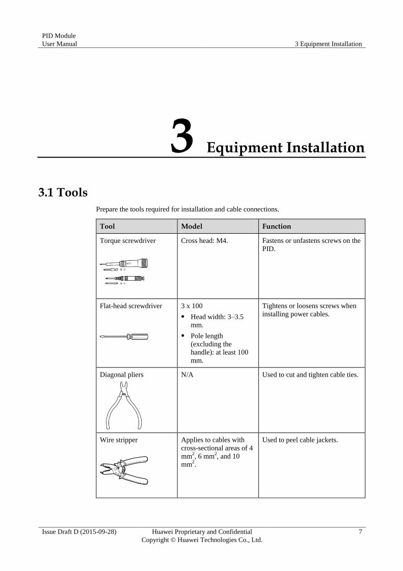
Prepare the tools required for installation and cable connections.
Tool Model Function
Torque screwdriver
Cross head: M4. Fastens or unfastens screws on the
PID.
Flat-head screwdriver
3 x 100
Head width: 3–3.5
mm.
Pole length
(excluding the
handle): at least 100
mm.
Tightens or loosens screws when
installing power cables.
Diagonal pliers
N/A Used to cut and tighten cable ties.
Wire stripper
Applies to cables with
cross-sectional areas of 4
mm2, 6 mm
2, and 10
mm2.
Used to peel cable jackets.

PID Module
User Manual 3 Equipment Installation
Issue Draft D (2015-09-28) Huawei Proprietary and Confidential
Copyright © Huawei Technologies Co., Ltd.
8
Tool Model Function
Guarded blade utility
knife
N/A Used to remove packing materials.
Cable cutter
Applies to cables with
cross-sectional areas of 4
mm2, 6 mm
2, and 10
mm2.
Cuts power cables.
Crimping tools
N/A Crimp power cables.
Tweezers
N/A Set the DIP switch.
Multimeter
N/A Checks grounding.
ESD gloves
N/A Operators wear ESD gloves when
installing equipment.

PID Module
User Manual 3 Equipment Installation
Issue Draft D (2015-09-28) Huawei Proprietary and Confidential
Copyright © Huawei Technologies Co., Ltd.
9
3.2 Determining the Installation Position
For the PID installed in a Huawei communications cabinet, cables are connected before
delivery. No installation operation is required. If the PID needs to be installed in a
non-Huawei communications cabinet, it is recommended that the PID be installed using a
guide rail. Determine the installation position by following the descriptions in this section.
Basic Requirements The installation methods and position must match the weight and dimensions of the
SUN2000. For details, see 9 Technical Specifications.
Do not store the PID in areas with flammable or explosive materials.
Installation Environment Requirements The ambient temperature must be below 60°C which ensures optimal PID operation and
extends the service life of the PID.
The protection level of the PID is IP20. It must be installed in a dry and clean indoor
environment.
Carrier Requirements The carrier where the PID is installed must be fireproof.
Do not install the PID on flammable building materials.
Verify that the surface on which the PID is installed is strong enough to bear the weight
of the PID.
Installation Space Requirements
Reserve enough clearance around the PID to ensure sufficient space for installation and heat
dissipation, as shown in Figure 3-1.

PID Module
User Manual 3 Equipment Installation
Issue Draft D (2015-09-28) Huawei Proprietary and Confidential
Copyright © Huawei Technologies Co., Ltd.
10
Figure 3-1 Installation space (unit: mm)
Installation Dimensions
Figure 3-2 shows the PID installation dimensions.

PID Module
User Manual 3 Equipment Installation
Issue Draft D (2015-09-28) Huawei Proprietary and Confidential
Copyright © Huawei Technologies Co., Ltd.
11
Figure 3-2 Installation dimensions (unit: mm)
3.3 Installation Using a Guide Rail
Procedure
Step 1 Install clip 1 and clip 2 on the upper and lower guide rails, and secure the clips to the upper
and lower guide rails each using two assembly screws (M4x10), as shown in Figure 3-3. The
tightening torque is 1.2 N·m.

PID Module
User Manual 3 Equipment Installation
Issue Draft D (2015-09-28) Huawei Proprietary and Confidential
Copyright © Huawei Technologies Co., Ltd.
12
Figure 3-3 Installing the clips
Step 2 Preinstall two assembly screws (M4x10) on the clip for the upper guide rail, and mount a rear
panel to the assembly screws through the cucurbit holes on the panel, as shown in Figure 3-4.
Figure 3-4 Mounting a rear panel
Step 3 Adjust the position of the clip on the guide rail, and secure the rear panel to the clip using the
two assembly screws preinstalled in Step 2. The tightening torque of the four screws is 1.2
N·m, as shown in Figure 3-5.

PID Module
User Manual 3 Equipment Installation
Issue Draft D (2015-09-28) Huawei Proprietary and Confidential
Copyright © Huawei Technologies Co., Ltd.
13
Figure 3-5 Securing a rear panel
Step 4 Preinstall two assembly screws (M4x10) on the rear panel, as shown in Figure 3-6.
Figure 3-6 Preinstalling PID screws
Step 5 Mount the PID onto the assembly screws preinstalled in Step 4 through the cucurbit holes on
the PID, secure the PID to the rear panel using two assembly screws (M4x10), and tighten the
two assembly screws preinstalled in Step 4. The tightening torque of the four screws is 1.2
N·m, as shown in Figure 3-7.

PID Module
User Manual 3 Equipment Installation
Issue Draft D (2015-09-28) Huawei Proprietary and Confidential
Copyright © Huawei Technologies Co., Ltd.
14
Figure 3-7 Mounting the PID
Step 6 Tighten the anti-slip screws, as shown in Figure 3-8.
Figure 3-8 Tightening the anti-slip screws
----End

PID Module
User Manual 4 Electrical Connections
Issue Draft D (2015-09-28) Huawei Proprietary and Confidential
Copyright © Huawei Technologies Co., Ltd.
15
4 Electrical Connections
Context
The cable colors shown in the electrical connection drawings provided in this chapter are for
reference only. Select cables in accordance with local cable specifications (yellow-green wires
are only used for grounding).
4.1 Port Description
Figure 4-1 shows the ports on the PID.
Figure 4-1 Ports on the PID
The silk screen of port 6 may be different from the one in the figure because of the product change or
upgrade. The actual silk screen prevails. The port wiring sequence does not change.

PID Module
User Manual 4 Electrical Connections
Issue Draft D (2015-09-28) Huawei Proprietary and Confidential
Copyright © Huawei Technologies Co., Ltd.
16
Table 4-1 Description of ports on the PID
No. Port Name (Silk Screen) Description
1 Protective earthing (PE) bolt Provides ground protection.
2 RS485 port (RS485) Communicates with the SmartLogger using
the RS485 protocol.
Connect RS485+ to PIN1 and connect RS485-
to PIN3.
3 Reserved function port (+12V) Reserved.
4 Reserved function port
(GFDI/RCD)
Reserved.
5 PV port (PV2+, PV2-, PV1+,
PV1-)
Increases the voltage of the PV module to the
ground at night in the SUN8000 scenario.
6 Power grid input and PID output
port (GRID_PE/N/A/B/C)
PIN5, PIN7, and PIN9 are connected to the
three-phase power grid input, PIN3 is
connected to the virtual midpoint, and PIN1 is
connected to the PE cable.
4.2 Cable Connection Description
4.2.1 Application in the SUN2000 Scenario
Figure 4-2 shows the cable connection for the PID used in the SUN2000 scenario.

PID Module
User Manual 4 Electrical Connections
Issue Draft D (2015-09-28) Huawei Proprietary and Confidential
Copyright © Huawei Technologies Co., Ltd.
17
Figure 4-2 Cable connection for the SUN2000 scenario
The ground wire in cable 3 is the PID output wire used for function grounding. It must be
connected to the ground bar on the low-voltage side of the box-type transformer for reliable
grounding.
The inductor midpoint must not be connected to the N cable of the power grid or the ground.
The silk screen of port 6 may be different from the one in the figure because of the product change or
upgrade. The actual silk screen prevails. The port wiring sequence does not change.
Table 4-2 describes the cable specifications.
Table 4-2 Cable specifications
Cable No.
Cable Name Cable Specifications Description
1 Ground cable 10 AWG (4 mm2),
yellow-green, meeting the
UL1015 standard; OT: M6.
Prepared by the customer.
Ensure that the tightening
torque is 4 N·m.
2 RS485
communication
s cable
22 AWG (0.3 mm2),
symmetrical twisted pair cable
with two cores (brown and
black).
Delivered with the PID.

PID Module
User Manual 4 Electrical Connections
Issue Draft D (2015-09-28) Huawei Proprietary and Confidential
Copyright © Huawei Technologies Co., Ltd.
18
Cable No.
Cable Name Cable Specifications Description
3 Power grid
input and PID
output cables
A: 2 x 18 AWG (1 mm2),
red, meeting the UL1015
standard.
B: 2 x 18 AWG (1 mm2),
green, meeting the UL1015
standard.
C: 2 x 18 AWG (1 mm2),
yellow, meeting the
UL1015 standard.
N: 2 x 18 AWG (1 mm2),
blue, meeting the UL1015
standard.
PE: 2 x 18 AWG (1 mm2),
yellow-green, meeting the
UL1015 standard.
Delivered with the PID.
4.2.2 Application in the SUN8000 Scenario
Figure 4-3 shows the cable connection for the PID used in the SUN8000 scenario.

PID Module
User Manual 4 Electrical Connections
Issue Draft D (2015-09-28) Huawei Proprietary and Confidential
Copyright © Huawei Technologies Co., Ltd.
19
Figure 4-3 Cable connection for the SUN8000 scenario
A DC circuit breaker needs to be installed for cable 3 at the end close to the PID. The
recommended DC circuit breaker specifications are a rated operating voltage equal to or
greater than 1200 V DC and a rated operating current equal to or greater than 1 A.
The ground wire in cable 4 is the PID output wire used for function grounding. It must be
connected to the ground bar on the low-voltage side of the box-type transformer for
reliable grounding.
The inductor midpoint must not be connected to the N cable of the power grid or the ground.
The silk screen of port 6 may be different from the one in the figure because of the product change or
upgrade. The actual silk screen prevails. The port wiring sequence does not change.
Table 4-3 describes the cable specifications.
Table 4-3 Cable specifications
Cable No.
Cable Name Cable Specifications Description
1 Ground cable 10 AWG (4 mm2),
yellow-green, meeting the
UL1015 standard; OT: M6.
Prepared by the
customer. Ensure that
the tightening torque is
4 N·m.

PID Module
User Manual 4 Electrical Connections
Issue Draft D (2015-09-28) Huawei Proprietary and Confidential
Copyright © Huawei Technologies Co., Ltd.
20
Cable No.
Cable Name Cable Specifications Description
2 RS485
communications
cable
22 AWG (0.3 mm2),
symmetrical twisted pair cable
with two cores (brown and
black).
Delivered with the PID.
3 PV1+/-, PV2+/-
input cables
PV1+: 10 AWG (4 mm2),
red, meeting the UL1015
standard.
PV1-: 10 AWG (4 mm2),
blue, meeting the UL1015
standard.
PV2+: 10 AWG (4 mm2),
red, meeting the UL1015
standard.
PV2-: 10 AWG (4 mm2),
blue, meeting the UL1015
standard.
Prepared by the
customer.
4 Power grid input
and PID output
cables
A: 2 x 18 AWG (1 mm2),
red, meeting the UL1015
standard.
B: 2 x 18 AWG (1 mm2),
green, meeting the
UL1015 standard.
C: 2 x 18 AWG (1 mm2),
yellow, meeting the
UL1015 standard.
N: 2 x 18 AWG (1 mm2),
blue, meeting the UL1015
standard.
PE: 2 x 18 AWG (1 mm2),
yellow-green, meeting the
UL1015 standard.
Delivered with the PID.

PID Module
User Manual 5 Parameter Settings
Issue Draft D (2015-09-28) Huawei Proprietary and Confidential
Copyright © Huawei Technologies Co., Ltd.
21
5 Parameter Settings
5.1 Setting Communications Parameters
Communications parameters to be set for the PID include the baud rate and build-out resistor.
Context
Ensure that the circuit breaker on the PID AC side is turned off before setting communications
parameters.
In the PID, communications parameters are set using DIP switches.
Figure 5-1 describes the DIP switches.

PID Module
User Manual 5 Parameter Settings
Issue Draft D (2015-09-28) Huawei Proprietary and Confidential
Copyright © Huawei Technologies Co., Ltd.
22
Figure 5-1 DIP switches
No. Component Description
1 DIP switch S1 Specifies the connection status of the RS485 build-out resistor
which is disconnected by default before delivery. For details,
see Step 2.
2 DIP switch S2 Specifies the RS485 baud rate which is set to 9600 bps by
default before delivery. For details, see Step 3.
Procedure
Step 1 Loosen the two captive screws on the PID and remove the front panel, as shown in Figure 5-2.

PID Module
User Manual 5 Parameter Settings
Issue Draft D (2015-09-28) Huawei Proprietary and Confidential
Copyright © Huawei Technologies Co., Ltd.
23
Figure 5-2 Removing the front panel
Step 2 Configure the connection status of the RS485 build-out resistor using DIP switches, as shown
in Figure 5-3.
The connection status of the RS485 build-out resistor can be set to connected or
disconnected. This parameter is set to disconnected by default. If signals are distorted or the
communication is of poor quality because of a lengthy communications cable, set the
parameter to connected.
Figure 5-3 DIP switch S1
In Figure 5-3, the RS485 build-out resistor is set to the default status, that is, disconnected.
Connection Status of RS485 Built-out Resistor
DIP1 DIP2
Connect ON ON

PID Module
User Manual 5 Parameter Settings
Issue Draft D (2015-09-28) Huawei Proprietary and Confidential
Copyright © Huawei Technologies Co., Ltd.
24
Connection Status of RS485 Built-out Resistor
DIP1 DIP2
Disconnect (default) OFF OFF
If the PID is connected to the COM port on the SmartLogger, and the COM port is not connected to
other devices such as inverters, as shown in Figure 5-4, set the connection status of the RS485
build-out resistor to connected.
If the PID is connected to the COM port on the SmartLogger, and the COM port is connected to
other devices such as inverters, as shown in Figure 5-5, set the connection status of the RS485
build-out resistor to disconnected.
Figure 5-4 Connection method 1
Figure 5-5 Connection method 2
Step 3 Set the RS485 baud rate using DIP switches, as shown in Figure 5-6.
The available baud rates include 4800 bps, 9600 bps, 19200 bps, and 115200 bps.

PID Module
User Manual 5 Parameter Settings
Issue Draft D (2015-09-28) Huawei Proprietary and Confidential
Copyright © Huawei Technologies Co., Ltd.
25
Figure 5-6 DIP switch S2
In Figure 5-6, the RS485 baud rate is set to the default value 9600 bps.
RS485 Baud Rate DIP1 DIP2
9600 (default) ON ON
4800 OFF ON
19200 ON OFF
115200 OFF OFF
Step 4 Reinstall the front panel.
----End
5.2 Setting the PV Module Type
Context
Before maintaining or replacing a PID, ensure that:
The circuit breaker on the PID AC side is turned off in a SUN2000 scenario.
The circuit breakers on the PID DC and AC sides are turned off in a SUN8000 scenario.

PID Module
User Manual 5 Parameter Settings
Issue Draft D (2015-09-28) Huawei Proprietary and Confidential
Copyright © Huawei Technologies Co., Ltd.
26
The PID is a component of a SUN2000 or SUN8000 power station array with a power of 1
MW to 2 MW. PV modules used in the array must be of the same type (P or N). Ensure that
the PID setting is consistent with the PV module type. Otherwise, the effect of using the PID
to prevent potential induced degradation is affected.
The PV module type is set using jumper terminals in the PID.
Figure 5-7 describes the jumper terminal ports.
Figure 5-7 Jumper terminal ports
No. Component Description
1 Jumper
terminal J61
port
Used for a power station using P-type PV modules. The jumper
is inserted in the J61 port by default before delivery.
2 Jumper
terminal J62
port
Used for a power station using N-type PV modules.
For details about the PV module type, consult the manufacturer.

PID Module
User Manual 5 Parameter Settings
Issue Draft D (2015-09-28) Huawei Proprietary and Confidential
Copyright © Huawei Technologies Co., Ltd.
27
Procedure
Step 1 Loosen the two captive screws on the PID and remove the front panel, as shown in Figure 5-8.
Figure 5-8 Removing the front panel
Step 2 Insert the jumper in the corresponding port based on the type of PV modules used in a power
station.
If a power station uses PV modules of the P type, insert the jumper in the J61 port, as
shown by (1) in Figure 5-7.
If a power station uses PV modules of the N type, insert the jumper in the J62 port, as
shown by (2) in Figure 5-7.
Step 3 Reinstall the front panel.
----End
PID Module
User Manual 6 System Operation
Issue Draft D (2015-09-28) Huawei Proprietary and Confidential
Copyright © Huawei Technologies Co., Ltd.
28
6 System Operation
6.1 Checking Before Power-on
To ensure the normal PID operating, check the PID before powering it on.
Before powering on the PID, check that:
1. The PID is installed correctly and securely.
2. The ground cable is securely connected.
3. The power grid input and PID output cables are securely connected.
4. The RS485 communications cable is securely connected.
5. Verify that communications parameters are correctly set. For details, see 5.1 Setting
Communications Parameters.
6. Verify that the PV type is correctly set. For details, see 5.2 Setting the PV Module Type.
6.2 Powering on and Commissioning
Context
The PID output voltage is automatically capped to ensure the safety of a PV power plant. For
example, the voltage caps are respectively 500 V and 200 V for SUN2000 and SUN8000. The
output voltage is also related to the power grid voltage and PV voltage.
PID parameters can be set on the WebUI or LCD of the SmartLogger. This section uses
parameter settings on the WebUI as an example. For information about parameter settings on
the LCD, see the SmartLogger1000 User Manual.
Procedure
Step 1 Turn the power switch of the PID to ON to power on the PID.
If the PID is installed in a communications cabinet, the power switch is inside the communications
cabinet. If the PID is used in other scenarios, the power switch may be located in different places based
on the actual situation.

PID Module
User Manual 6 System Operation
Issue Draft D (2015-09-28) Huawei Proprietary and Confidential
Copyright © Huawei Technologies Co., Ltd.
29
Step 2 Enter https://xxx.xxx.xxx.xxx in the address box of the browser, and press Enter. The login
page is displayed, as shown in Figure 6-1. Set User Name to Advanced User (for required
user rights), specify Password, select a value for Language, and click Login.
If web pages cannot be opened, specify security settings for the browser. For details, see Preparations
for Login in the SmartLogger1000 User Manual.
Figure 6-1 Login page of the WebUI
xxx.xxx.xxx.xxx is the IP address of the SmartLogger, for example, https://192.168.0.10.
The preset password is 000001 in SmartLogger1000 V100R001C95SPC010 or earlier and is
Changeme in SmartLogger1000 V100R001C95SPC020 or later.
After the first login, it is recommended that you change the initial password immediately to ensure
account security.
Step 3 On the Maintenance tab page, choose Device Mgmt. > Connect Device, as shown in Figure
6-2.
If the PID is not found, check whether the RS485 cable is properly connected.

PID Module
User Manual 6 System Operation
Issue Draft D (2015-09-28) Huawei Proprietary and Confidential
Copyright © Huawei Technologies Co., Ltd.
30
Figure 6-2 Searching a Device
Step 4 On the Monitoring tab page, select a PID to be set and click Running Param.. The running
parameters settings page is displayed, as shown in Figure 6-3.
Figure 6-3 Setting running parameters
The running parameters settings page is for the SmartLogger SUN2000V100R001C95SPC101. The
page for a version earlier than V100R001C95SPC101 is different.
Running parameters cannot be set if the PID is in the Disconnect state.
Table 6-1 describes the parameters.

PID Module
User Manual 6 System Operation
Issue Draft D (2015-09-28) Huawei Proprietary and Confidential
Copyright © Huawei Technologies Co., Ltd.
31
Table 6-1 Running parameter descriptions
No.
Parameter Name
Function Parameter Value Description
1 Offset
mode
Specifies the
offset mode of the
PID.
Disabled Set this parameter to Disableif the PID is not
required.
N/PE Set this parameter to N/PE if the PID is
required to use voltage output from the
inductor virtual midpoint N.
PV/PE This mode applies only to the SUN8000
Networking Scenario (see Figure 2-3). Set this
parameter to PV/PE if the PID is required to
use voltage output from the negative PV
terminal.
Automatic In the SUN2000 Networking Scenario (see
Figure 2-2). Automatic indicates the N/PE
offset mode.
In theSUN8000 Networking Scenario (see
Figure 2-3). Set this parameter to
Automatic if the PID is required to
automatically switch between N/PE and
PV/PE offset modes based on the PV
module voltage.
2 Output
enabled
Specifies whether
PID output is
enabled.
Enable Set this parameter to Enable to allow the PID
output.
Disable Set this parameter to Disable to forbid the PID
output.
3 PV type Specifies the type
of the PV module
used in the power
station. For details
about the PV
module type,
consult the
manufacturer.
P-type Set this parameter to P-type if the PV module
type is P. In this case, the PID output voltage is
positive.
N-type Set this parameter to N-type if the PV module
type is N. In this case, the PID output voltage
is negative.
4 PV/PE
offset volt.
Specifies the DC
voltage when the
offset mode is set
to PV/PE.
N/A It is recommended that the offset voltage be set
to a value ranging from 50 V to 200 V.
5 Operation
mode
Specifies whether
the PID is
currently working
in normal or
commissioning
mode.
Commissioning In the commissioning mode, set the output
mode to PV/PE or N/PE, and set Output
enabled to Enable. The PID generates output
based on the configured voltage.
NOTE
Before the first power-on, to check whether the PID
functions properly, it is recommended that
Operation mode be set to Commissioning.

PID Module
User Manual 6 System Operation
Issue Draft D (2015-09-28) Huawei Proprietary and Confidential
Copyright © Huawei Technologies Co., Ltd.
32
No.
Parameter Name
Function Parameter Value Description
Normal In normal mode, the PID must be connected to
inverters and the data collector, and start
working automatically.
NOTE
After checking that the PID functions properly (by
performing Step 5 to Step 7), Operation mode can
be set to Normal.
6 Commiss.
out. volt.
Specifies the
output voltage
when the PID
works in
commissioning
mode.
N/A The value range is 0–500 V. It is
recommended that the commissioning voltage
be set to a value ranging from 50 V to 400 V.
NOTE
Commissioning output voltage is 200 V if the PID is
connected to the SUN8000.
7 Data Clear Data that can be
cleared includes
active alarms,
historical alarms,
and performance
data.
Starting When the Data Clear operation is performed
on the WebUI for the PID, the operation must
also be performed on the SmartLogger;
otherwise, data will not be cleared.
8 DC
voltage
max.
Specifies the
PV-PE voltage
when the normal
operation mode is
used.
N/A In normal operation mode, if the PV module
type is P, the parameter value indicates the
highest DC voltage between PV+ and PE; if
the PV module type is N, the parameter value
indicates the highest DC voltage between
PV-and PE. The value range is 500–1500 V.
Step 5 Set Operation mode to Commissioning, enter a value for Commiss. out. volt., use a
multimeter that is set to the DC position to measure the output voltage (midpoint voltage to
earth), and check whether the output voltage is close to the configured voltage.
Table 6-2 Supported running parameters in commissioning mode
Operation Mode
PV Module Type
Inverter Type
Offset Mode
Enable/Disable Disabled
N/PE PV/PE Automatic
Commissi
oning
P
SUN200
0 × √ × ×
Enable/Disable
SUN800
0 × √ √ ×
N
SUN200
0 × √ × ×
SUN800
0 × √ √ ×

PID Module
User Manual 6 System Operation
Issue Draft D (2015-09-28) Huawei Proprietary and Confidential
Copyright © Huawei Technologies Co., Ltd.
33
Step 6 Use a multimeter that is set to the DC position to measure the three-phase (A/B/C) voltage of
the power grid (A/B/C) to earth, and check whether the voltage is the same as the configured
voltage.
If the voltage is different from the configured voltage, check whether the PID output cables
are correctly connected to the inductor, whether the inductor is correctly connected to the
power grid, and whether the PID is properly grounded.
Step 7 Set Operation mode to Normal and verify that the PID works properly.
Wait 10–15 minutes after the PID is connected to the SmartLogger for the first time. When the
SmartLogger page displays the running status as Running, the PID runs properly.
To check whether the PID in the system functions properly, disconnect the PV input terminal (PV-
for P PV modules and PV+ for N PV modules) of an inverter, use a multimeter set to the DC
position to measure the voltage between the PV terminal and the ground (voltage between PV- and
the ground is greater than 0 for P PV modules and the voltage between PV+ and the ground is less
than 0 for N PV modules).
Table 6-3 Supported running parameters in normal mode
Operation Mode
PV Module Type
Inverter Type
Offset Mode
Enable/Disable Disabled
N/PE PV/PE Automatic
Normal
P SUN2000 √ √ × √
Enable/Disable SUN8000 √ √ √ √
N SUN2000 √ √ × ×
SUN8000 √ √ × ×
The default RS485 communications address of the PID is 1. If the RS485 communications address needs
to be changed, change it after choosing Addr. Allocate > Addr. Adjustment on the WebUI or LCD of
the SmartLogger. For details, see Managing Devices in the SmartLogger1000 User Manual.
----End

PID Module
User Manual 7 Device Maintenance
Issue Draft D (2015-09-28) Huawei Proprietary and Confidential
Copyright © Huawei Technologies Co., Ltd.
34
7 Device Maintenance
7.1 Troubleshooting
This section describes the common faults and troubleshooting measures for the PID.
If operations such as connecting cables or opening the front cover are involved during
troubleshooting, you must switch off the circuit breaker on the AC side and that on the DC
side (if any) of PID. Then wait for at least 1 minute and perform operations on the PID.
For details, see Table 7-1.
Table 7-1 Common faults and troubleshooting measures
No. Symptom Possible Cause Measure
1 The PID cannot be
powered on.
1. The three-phase power grid input
ports for the PID are disconnected
from cables or loosely connected to
cables.
2. The power grid is disconnected
from power.
3. The PID is faulty.
1. Check whether the three-phase
power grid input ports for the PID
are disconnected from cables or
loosely connected to cables. If yes,
reconnect them securely.
2. Check whether power is available to
the power grid.
3. Contact the supplier or Huawei
technical support.

PID Module
User Manual 7 Device Maintenance
Issue Draft D (2015-09-28) Huawei Proprietary and Confidential
Copyright © Huawei Technologies Co., Ltd.
35
No. Symptom Possible Cause Measure
2 The SmartLogger
cannot find the
PID.
1. The RS485 port is not connected to
the SmartLogger, or the cable
between the RS485 port and the
SmartLogger is loose, drops off, or
is reversely connected.
2. The RS485 communications
parameters or the build-out resistor
is set incorrectly.
3. The RS485 communications address
of the PID is outside the search
scope configured for the
SmartLogger.
4. The RS485 communications address
of the PID is the same as the
communications address of another
device connected to the
SmartLogger.
5. The SmartLogger version and the
PID version do not match.
1. Check the RS485 communications
cable connection. If any cable is
loose, drops off, or is reversely
connected, rectify the connection.
2. Check the settings of the RS485
communications parameters or the
build-out resistor. Ensure that the
baud rate or build-out resistor is set
correctly.
3. Set the RS485 communications
address of the PID to be within the
search scope configured for the
SmartLogger.
4. Reset the RS485 communications
address of the PID.
5. Download the
SUN2000V100R001C71 Release Notes from
http://support.huawei.com, and
upgrade the PID software version to
the required version.
3 The PID status is
displayed as
disconnected on
the SmartLogger.
1. The cable between the PID and the
SmartLogger is loose or
disconnected.
2. The PID is disconnected from
power.
3. The baud rate or RS485
communications address of the PID
is changed.
4. The PID is replaced.
5. The PID is no longer connected.
1. Verify that the cable between the
PID and the SmartLogger is
properly connected and tightened.
2. After checking that the PID is
connected properly, power on the
PID.
3. Verify the baud rate and RS485
communications address of the PID.
4. Check whether the PID has been
replaced. If yes, search for the PID
again or manually add the PID on
the SmartLogger.
5. If the PID is removed, remove it on
the SmartLogger.
7.2 Alarms
This section describes common alarms and alarm handing suggestions.

PID Module
User Manual 7 Device Maintenance
Issue Draft D (2015-09-28) Huawei Proprietary and Confidential
Copyright © Huawei Technologies Co., Ltd.
36
If operations such as connecting cables or opening the front cover are involved during alarm
handing, you must switch off the circuit breaker on the AC side and that on the DC side (if
any) of PID. Then wait for at least 1 minute and perform operations on the PID.
For details, see Table 7-2.
It takes 3 minutes for an alarm to display on the SmartLogger user interface after a fault occurs.
Table 7-2 Alarms
Alarm ID
Alarm Severity Cause Impact on the System
Measure
1900 PV1
Reverse
Major PV1 is
reversely
connected.
The PID does not
work.
1. Check whether PV1+ and
PV1- are reversely
connected. If yes, reconnect
the cables.
2. If the cable connection is
correct, contact Huawei
technical support.
1903 Module
overtemp.
Major The
temperature of
the PID is
excessively
high.
The PID does not
work and
generates no
output.
1. Check the PID installation
environment and verify
whether the heat dissipation
is normal. If no, relocate the
PID.
2. If the heat dissipation is
normal but the fault persists,
contact Huawei technical
support.
1914 Output
overcur.
Major The load
current exceeds
the alarm
threshold.
The PID does not
work and
generates no
output. The fault
can be
automatically
rectified.
If the fault occurs frequently,
contact Huawei technical
support.
1917 Grid volt.
imbal.
Major The three
phases of the
power grid
differ greatly in
voltage.
The PID does not
work and
generates no
output. The fault
can be
automatically
rectified.
If the fault occurs frequently,
contact Huawei technical
support.

PID Module
User Manual 7 Device Maintenance
Issue Draft D (2015-09-28) Huawei Proprietary and Confidential
Copyright © Huawei Technologies Co., Ltd.
37
Alarm ID
Alarm Severity Cause Impact on the System
Measure
1918 Grid
overvolt.
Major The power grid
line voltage
exceeds the
upper
threshold.
The PID does not
work and
generates no
output. The fault
can be
automatically
rectified.
If the fault occurs frequently,
contact Huawei technical
support.
1919 Grid
undervolt.
Major The power grid
line voltage is
lower than the
lower
threshold.
The PID does not
work and
generates no
output. The fault
can be
automatically
rectified.
If the fault occurs frequently,
contact Huawei technical
support.
1920 Incorrect
PV mode
Major In
commissioning
or normal
mode, running
parameter
settings are
incorrect.
The PID does not
work and
generates no
output.
1. Check whether running
parameters are correct. For
details, see Table 6-2 and
Table 6-3.
2. If the PV type is correctly set
but the fault persists, contact
Huawei technical support.
1921 Incorrect
wiring
Major 1. The output
cable is not
connected
or in poor
contact.
2. The ground
cable is not
connected
or in poor
contact.
The PID does not
work and
generates no
output.
1. Reconnect the output cable
securely.
2. Reconnect the ground cable
securely.
1924 Grid Loss Major The power grid
is power off.
The PID does not
work.
1. If the fault occurs
accidentally, the possible
cause is that the power grid
is power off temporarily. The
PID automatically recovers
after the power grid becomes
normal.
2. If the alarm occurs
repeatedly, contact Huawei
technical support.

PID Module
User Manual 7 Device Maintenance
Issue Draft D (2015-09-28) Huawei Proprietary and Confidential
Copyright © Huawei Technologies Co., Ltd.
38
Alarm ID
Alarm Severity Cause Impact on the System
Measure
1925 Grid
overfreq.
Major The power grid
frequency
exceeds the
upper threshold
of the PID
working
frequency.
The PID does not
work.
1. If the fault occurs
accidentally, the possible
cause is that the power grid
is abnormal temporarily. The
PID automatically recovers
after the power grid becomes
normal.
2. If the alarm occurs
repeatedly, contact Huawei
technical support.
1926 Grid
underfreq.
Major The power grid
frequency is
lower than the
lower threshold
of the PID
working
frequency.
The PID does not
work.
1. If the fault occurs
accidentally, the possible
cause is that the power grid
is abnormal temporarily. The
PID automatically recovers
after the power grid becomes
normal.
2. If the alarm occurs
repeatedly, contact Huawei
technical support.
1927 Incorrect
PV mod
type
Major The PV type is
incorrectly set.
The PID does not
work.
1. Check whether the PV type
is correctly set. If no, correct
the PV type setting.
2. If the PV type is correctly set
but the fault persists, contact
Huawei technical support.
1928 PID
inductor
fault
Major 1. The PID
inductor
cable is
incorrectly
connected.
2. The PID
inductor is
faulty.
The PID does not
work and
generates no
output. The fault
can automatically
disappear.
1. Check whether the PID
inductor cable is connected
properly. If the cable is not
connected properly,
reconnect the cable.
2. If the PID inductor cable is
connected properly, replace
the PID inductor or contact
Huawei technical support.
1929 PV2
Reverse
Major PV2 is
reversely
connected.
The PID does not
work.
1. Check whether PV2+ and
PV2- are reversely
connected. If yes, reconnect
the cables.
2. If the cable connection is
correct, contact Huawei
technical support.

PID Module
User Manual 7 Device Maintenance
Issue Draft D (2015-09-28) Huawei Proprietary and Confidential
Copyright © Huawei Technologies Co., Ltd.
39
Alarm ID
Alarm Severity Cause Impact on the System
Measure
1930 Device fault Major A fault caused
by incorrect
device settings
or cable
connections or
PID exceptions.
The PID does not
work and
generates no
output.
Reason ID = 5
1. Check whether the output
virtual midpoint and PE
are short-circuited, or the
output impedance is less
than 1 kilohm. If yes,
reconnect the cable
securely.
2. Check the cable
connections for the
output virtual midpoint
and the PE cable, which
should not be connected
to cables on the power
grid side. If they are
connected to cables on
the power grid side,
reconnect the cables.
3. If no, replace the PID or
contact Huawei technical
support.
Reason ID = 6
1. Check whether
PV1-/PV2- and PE are
short-circuited, or the
output impedance is less
than 1 kilohm. If yes,
reconnect the cable
securely.
2. If no, replace the PID or
contact Huawei technical
support.
Reason ID = 9
1. Check whether the baud
rate settings on the data
collector and PID are the
same.
2. Check whether the
RS485 cable is connected
properly.
3. If the fault occurs
repeatedly, replace the
PID or contact Huawei
technical support.
For other reason IDs
Please replace the PID or
contact Huawei technical support.

PID Module
User Manual 8 PID Disposal
Issue Draft D (2015-09-28) Huawei Proprietary and Confidential
Copyright © Huawei Technologies Co., Ltd.
40
8 PID Disposal
This section describes how to dispose of the PID.
If the PID service life has expired, dispose of the PID in accordance with local rules for
disposal of electrical equipment waste.

PID Module
User Manual 9 Technical Specifications
Issue Draft D (2015-09-28) Huawei Proprietary and Confidential
Copyright © Huawei Technologies Co., Ltd.
41
9 Technical Specifications
This section describes technical specifications of the PID.
Table 9-1 Technical specifications
Item Specifications
Operating temperature range -25ºC to +60ºC
Relative humidity (non-condensing) 5%–95%
Operating altitude 4000 m
Degree of protection IP20
Class of protection Class I
Input Three-phase line voltage Rated voltage range: 320–480 V AC
Operating voltage range: 270–620 V AC
Rated frequency 50/60 Hz
Maximum input current 0.3 A AC
Output Output voltage range 50–500 V DC
Maximum output
current
0.2 A DC

PID Module
User Manual A Acronyms and Abbreviations
Issue Draft D (2015-09-28) Huawei Proprietary and Confidential
Copyright © Huawei Technologies Co., Ltd.
42
A Acronyms and Abbreviations
L
LCD Liquid Crystal Display
P
PE Protective Earthing
PID Potential Induced Degradation
PV Photo Voltaic
S
SPD Surge Protective Device

PID Module
User Manual B Installing an Inductor and Connecting Cables
Issue Draft D (2015-09-28) Huawei Proprietary and Confidential
Copyright © Huawei Technologies Co., Ltd.
43
B Installing an Inductor and Connecting Cables
Appearance
Figure B-1 shows the appearance and dimensions of an inductor.
Figure B-1 Inductor (unit: mm)
Installation
Figure B-2 shows the installation dimensions of an inductor.

PID Module
User Manual B Installing an Inductor and Connecting Cables
Issue Draft D (2015-09-28) Huawei Proprietary and Confidential
Copyright © Huawei Technologies Co., Ltd.
44
Figure B-2 Installation dimensions (unit: mm)
Space for installing an inductor (H x W x D): 150 mm x 150 mm x 150 mm.
Screw model for installing an inductor: M5x12; 4 PCS.
Cable Connection
Figure B-3 shows how to connect cables between an inductor and the PID.
Figure B-3 Cable connection
Recommended cable: 18 AWG (1 mm2); meeting the UL1015 standard.
A circuit breaker (480 V AC/6 A) can be installed at the power grid side or between the PID and
inductor depending on the actual situation.