Embed Size (px)
Citation preview

ACC4100
Diesel Air Compressor Controller
User Manual
SMARTGEN (ZHENGZHOU) TECHNOLOGY CO.,LTD.

ACC4100 DIESEL AIR COMPRESSOR CONTROLLER USER MANUAL
ACC4100 Diesel Air Compressor Controller 2019-06-10 Version 1.0 Page 2 of 52
Chinese trademark
English trademark
SmartGen — make your generator smart
SmartGen Technology Co., Ltd.
No.28 Jinsuo Road
Zhengzhou City
Henan Province
P. R. China
Tel: 0086-(0)371-67988888/67981888
0086-(0)371-67991553/67992951
0086-(0)371-67981000(overseas)
Fax: 0086-(0)371-67992952
Web: www.smartgen.com.cn
www.smartgen.cn
Email: [email protected]
All rights reserved. No part of this publication may be reproduced in any material form (including
photocopying or storing in any medium by electronic means or other) without the written permission
of the copyright holder.
Applications for the copyright holder’s written permission to reproduce any part of this publication
should be addressed to SmartGen Technology at the address above.
Any reference to trademarked product names used within this publication is owned by their
respective companies.
SmartGen Technology reserves the right to change the contents of this document without prior notice.
Table 1 Software Version
Date Version Note
2019-06-10 1.0 Original release.

ACC4100 DIESEL AIR COMPRESSOR CONTROLLER USER MANUAL
ACC4100 Diesel Air Compressor Controller 2019-06-10 Version 1.0 Page 3 of 52
Table 2 Notation Clarification
Sign Instruction
NOTE Highlights an essential element of a procedure to ensure correctness.
CAUTION!
Indicates a procedure or practice, which, if not strictly observed, could result in
damage or destruction of equipment.
WARNING!
Indicates a procedure or practice, which could result in injury to personnel or
loss of life if not followed correctly.
ACC4100 DIESEL AIR COMPRESSOR CONTROLLER USER MANUAL
ACC4100 Diesel Air Compressor Controller 2019-06-10 Version 1.0 Page 4 of 52
CONTENT
1 OVERVIEW .............................................................................................................................................. 6
2 PERFORMANCE AND CHARACTERISTICS ........................................................................................... 7
3 SPECIFICATION ...................................................................................................................................... 8
4 OPERATION ............................................................................................................................................ 9
4.1 KEY FUNCTION DESCRIPTION ....................................................................................................... 9
4.2 CONTROLLER PANEL .................................................................................................................... 10
4.3 START/STOP OPERATION ............................................................................................................ 10
4.4 START OPERATION FOR FUEL PRE-SUPPLY OUTPUT SETTING ............................................... 11
4.5 EMERGENCY START ..................................................................................................................... 11
4.6 LOAD/UNLOAD SPEED REGULATION PROCESS OF AIR COMPRESSOR .................................. 11
5 MANUAL DPF REGENERATION ........................................................................................................... 12
5.1 ILLUSTRATION .............................................................................................................................. 12
5.2 PANEL ICON DESCRIPTION OF DPF REGENERATION................................................................ 13
5.3 DPF MANUAL REGENERATION OPERATION .............................................................................. 13
6 PROTECTION ........................................................................................................................................ 15
6.1 WARNINGS .................................................................................................................................... 15
6.2 SHUTDOWNS ................................................................................................................................. 16
7 WIRE CONNECTION ............................................................................................................................. 18
8 CONFIGURATION PARAMETER RANGE AND DEFINITION ................................................................ 20
8.1 PARAMETER RANGE AND DEFINITION ....................................................................................... 20
8.2 DEFINABLE CONTENTS OF FLEXIBLE OUTPUT PORTS 1-6....................................................... 29
8.3 DEFINED CONTENTS OF CONFIFURABLE INPUT PORTS .......................................................... 34
8.4 SELECTION OF SENSORS ............................................................................................................. 36
8.5 CONDITIONS OF CRANK DISCONNECT SELECTION .................................................................. 37
8.6 MAINTENANCE SETTING ............................................................................................................. 37
9 PARAMETERS SETTING ...................................................................................................................... 38
10 SENSOR SETTING .............................................................................................................................. 40
11 COMMISSIONING ............................................................................................................................... 41
12 TYPICAL WIRING DIAGRAM .............................................................................................................. 41
13 INSTALLATION ................................................................................................................................... 42
14 CONNECTIONS OF CONTROLLER WITH J1939 ENGINE ................................................................ 43
14.1 CUMMINS ISB/ISBE .................................................................................................................... 43
14.2 CUMMINS QSL9 .......................................................................................................................... 43
14.3 CUMMINS QSM11(IMPORT) ...................................................................................................... 44
14.4 CUMMINS QSX15-CM570 .......................................................................................................... 44
14.5 CUMMINS GCS-MODBUS ........................................................................................................... 45
14.6 CUMMINS QSM11 ....................................................................................................................... 45
14.7 CUMMINS QSZ13 ........................................................................................................................ 46
14.8 DETROIT DIESEL DDEC III / IV .................................................................................................... 46
14.9 DEUTZ EMR2 ............................................................................................................................... 47
14.10 JOHN DEERE ............................................................................................................................. 47
14.11 MTU MDEC ................................................................................................................................ 47

ACC4100 DIESEL AIR COMPRESSOR CONTROLLER USER MANUAL
ACC4100 Diesel Air Compressor Controller 2019-06-10 Version 1.0 Page 5 of 52
14.12 MTU ADEC(SMART MODULE) .................................................................................................. 48
14.13 MTU ADEC (SAM MODULE) ..................................................................................................... 48
14.14 PERKINS .................................................................................................................................... 48
14.15 SCANIA ...................................................................................................................................... 49
14.16 VOLVO EDC3 ............................................................................................................................. 49
14.17 VOLVO EDC4 ............................................................................................................................. 49
14.18 VOLVO-EMS2 ............................................................................................................................. 50
14.19 YUCHAI ...................................................................................................................................... 50
14.20 WEICHAI .................................................................................................................................... 50
15 TROUBLE SHOOTING ......................................................................................................................... 51
16 PACKING LIST .................................................................................................................................... 52

ACC4100 DIESEL AIR COMPRESSOR CONTROLLER USER MANUAL
ACC4100 Diesel Air Compressor Controller 2019-06-10 Version 1.0 Page 6 of 52
1 OVERVIEW
ACC4100 Diesel Air Compressor Controller is used for air compressor with diesel-driven engine in
order to realize functions of compressor start/stop, data measurement, maintenance, alarm protection
and "three remotes". It has speed regulator function, and CANBUS (SAE J1939) port, which can control
various ECU or non-ECU diesel-driven air compressor.
ACC4100 Diesel Air Compressor Controller applies 32-bit ARM micro-processor technology, which
can realize functions of precise measurement for many parameters, set-point adjustment, timing and
threshold setting etc. A majority of parameters can be adjusted from the control panel. All parameters
can be adjusted and monitored on PC by RS485 or USB port. It can be widely used for diesel-driven air
compressor control system with compact structure, simple wiring, and high reliability.

ACC4100 DIESEL AIR COMPRESSOR CONTROLLER USER MANUAL
ACC4100 Diesel Air Compressor Controller 2019-06-10 Version 1.0 Page 7 of 52
2 PERFORMANCE AND CHARACTERISTICS
Main characteristics are as follows:
— 132x64 LCD display with backlit; Optional Chinese and English languages; Simple operation
interface;
— Screen protection is hard screen of Acrylic material with better wear-resisting and scratch resistant
qualities;
— Silicon panel and buttons with strong adaptive capacity of high/low temperature environment;
— RS485 communication port realizes "three remotes" function by MODBUS protocol;
CANBUS port can monitor ECU common data (speed, water temperature, load rate, fuel consumption
etc.).
— DPF regeneration function, which meets Euro V emission standard.
— 6 ways of analog sensors, 3 ways of fixed resistance types, and 3 ways of flexible
resistance/current/voltage types, both of them can precisely detects data of engine fuel level, air
compressor venting pressure, and venting temperature etc.
— Multiple temperature, pressure, and level sensor curves can used directly, and custom sensor curve
is also available.
— Can precisely collect all kinds of parameters of air compressor, which provides high water
temperature, low oil pressure, over speed, and under speed protection, and venting pressure high,
venting temperature high protection etc. with complete protection functions.
— Speed regulator function can automatically adjust speed according to venting pressure of the air
compressor.
— All outputs are relay outputs.
— Parameter setting function allows users to change and set the parameters, and at the same time
they are stored in internal EEPROM memory and will not get lost at outage.
— Crank disconnect conditions (speed, oil pressure) are optional.
— Speed can be obtained from speed sensor or charging generator W/L.
— Power supply range DC (8-35V), which can suits different battery voltage environment.
— Event log, real-time clock functions.
— Heater, cooler and fuel pump control functions;
— Maintenance function; maintenance time due action can be set.
— All parameters apply digital adjustment, getting rid of common potentiometer's analog regulation
method, and improving reliability and stability of the whole device.
— Sealing gasket is designed for enclosure with IP65 protection class.
Metal clips are used to fix the controller, and they are especially outstanding under high temperature
environment.
— Modular design, antiflaming ABS plastic shell, pluggable terminals, built-in mounting, compact
structure and easy installation.
ACC4100 DIESEL AIR COMPRESSOR CONTROLLER USER MANUAL
ACC4100 Diesel Air Compressor Controller 2019-06-10 Version 1.0 Page 8 of 52
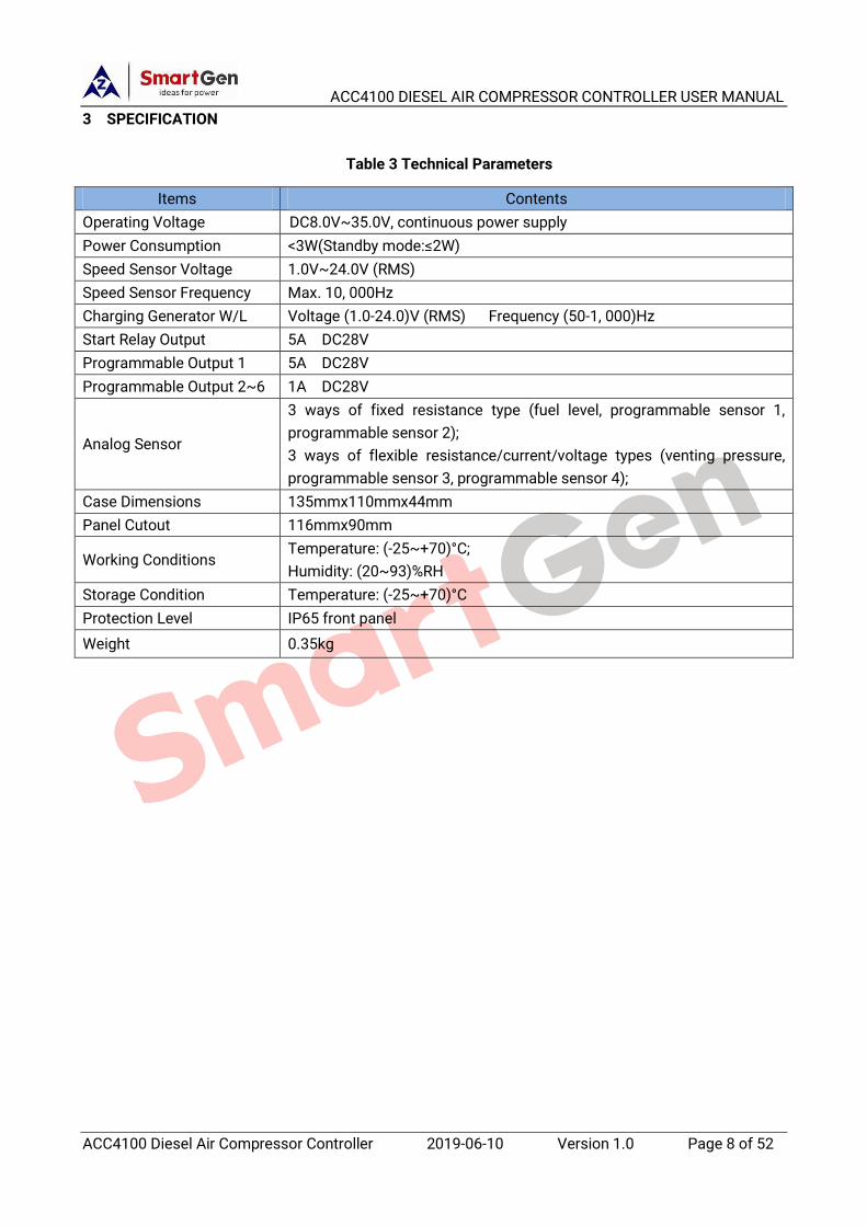
3 SPECIFICATION
Table 3 Technical Parameters
Items Contents
Operating Voltage DC8.0V~35.0V, continuous power supply
Power Consumption <3W(Standby mode:≤2W)
Speed Sensor Voltage 1.0V~24.0V (RMS)
Speed Sensor Frequency Max. 10, 000Hz
Charging Generator W/L Voltage (1.0-24.0)V (RMS) Frequency (50-1, 000)Hz
Start Relay Output 5A DC28V
Programmable Output 1 5A DC28V
Programmable Output 2~6 1A DC28V
Analog Sensor
3 ways of fixed resistance type (fuel level, programmable sensor 1,
programmable sensor 2);
3 ways of flexible resistance/current/voltage types (venting pressure,
programmable sensor 3, programmable sensor 4);
Case Dimensions 135mmx110mmx44mm
Panel Cutout 116mmx90mm
Working Conditions Temperature: (-25~+70)°C;
Humidity: (20~93)%RH
Storage Condition Temperature: (-25~+70)°C
Protection Level IP65 front panel
Weight 0.35kg

ACC4100 DIESEL AIR COMPRESSOR CONTROLLER USER MANUAL
ACC4100 Diesel Air Compressor Controller 2019-06-10 Version 1.0 Page 9 of 52
4 OPERATION
4.1 KEY FUNCTION DESCRIPTION
Table 4 Key Description
Icon Buttons Function Description
Start Makes the air compressor start under stop state.
Load/Unload
At idle speed state, press it and controller shall load and make relay
output; at normal running state, press it again and controller shall
unload and relay stops outputting.
Alarm Reset
Press it and it enters alarm page fast; press it again and alarm is
removed; after alarm reset, press it again and exit from alarm page.
Maintenance
Press it and it enters maintenance page; press it again and exit from
the page; press it longer at this page, it enters password interface;
input password and maintenance setting is entered.
Stop
1. Stop the running air compressor at start mode;
2. Press it for 3s or longer, test whether panel indicators are normal
(lamp test);
3. Press it again in stop process and it can be stopped faster.
Up/Increase
1. Scroll up;
2. Move up cursor or increase the value in setting menu.
Down/Decrease
1. Scroll down;
2. Move down cursor or decrease the value in setting menu.
Set/Confirm
1. In main screen, press it and it enters parameter setting menu;
2. Confirm set information in settings.

ACC4100 DIESEL AIR COMPRESSOR CONTROLLER USER MANUAL
ACC4100 Diesel Air Compressor Controller 2019-06-10 Version 1.0 Page 10 of 52
4.2 CONTROLLER PANEL
Fig. 1 Front Panel Description
NOTE: Description for parts of the indicators:
Alarm Indicator: slow flash (once per second) for warning alarm; quick flash (5 times per second) for stop alarm; light off
for none alarms;
Status Indicator: it illuminates always as air compressor is normally running.
4.3 START/STOP OPERATION
4.3.1 START SEQUENCE
a) Press and start air compressor;
b) If pre-heat time is configured, then pre-heat relay outputs; LCD displays "pre-heat delay xx";
c) After pre-heat delay is over, fuel relay outputs the pre-set fuel time before start (default: 1s), then
start relay outputs; If air compressor crank disconnect fails during "start time", then fuel relay and
start relay stop outputting, and enter "crank rest time", waiting for next start;
d) During the pre-set start attempts, if air compressor doesn't succeed to start, then controller issues
failed to start signal and stops, and meanwhile LCD alarm page displays "Failed to Start" alarm;
e) During any one of the start attempts, if crank disconnect is fulfilled, then it enters "Safety On Delay",
during which oil pressure low, water temperature high, under speed, and charge alt fail alarms are
all inactive; after safety on delay it enters "Start Idle Time" (if configured);
f) During start idle speed process, under speed alarm is inactive; after "Start Idle Time" it enters idle
running; if Load key is pressed, then load control outputs and it enters "Warming Up Time" (if
configured);
g) When warning up time is ended, air compressor enters normal running status; if speed is abnormal,
controller shall issue alarms and stops it (LCD alarm page displays alarm information.).
4.3.2 STOP SEQUENCE
a) Press , and stop the running air compressor; before stop if load control outputs, then

ACC4100 DIESEL AIR COMPRESSOR CONTROLLER USER MANUAL
ACC4100 Diesel Air Compressor Controller 2019-06-10 Version 1.0 Page 11 of 52
disconnect load control;
b) If "Warming Up Time" is configured, then "warming up time" starts; when warming up delay is over,
it enters "Stop Idle Time";
c) When it enters stop idle time (if configured), then idle relay is energized to output;
d) It enters "ETS Solenoid Hold", and ETS relay is energized to output; fuel relay output is
disconnected;
e) It enters "Wait Stop Time", and automatically judges whether it stops completely;
f) When air compressor stops completely, it enters "After Stop Time"; Otherwise controller enters
stop failure and issues "Failed to Stop" alarm (after the alarm, if air compressor stops completely,
then it enters "After Stop Time", and meanwhile Failed to Stop alarm is removed automatically.).
4.4 START OPERATION FOR FUEL PRE-SUPPLY OUTPUT SETTING
When output port is configured to "Fuel Pre-supply Output", and press to start the air
compressor:
If the set pre-supply time is less than or equal to pre-heat time, LCD displays "Pre-heat Delay xx",
pre-heat relay outputs (if configured) and pre-supply relay outputs (output for the pre-set pre-supply
time); after pre-heat delay is over, fuel relay outputs the pre-set fuel time (default: 1s) before start, then
start relay outputs; the following start process is the same as the START OPERATION (for start process
please see 4.3.1d)~g)).
If the set pre-supply time is more than the pre-heat time, pre-supply relay outputs in pre-heat delay
phase; after pre-heat delay is over, the following pre-supply time enters pre-supply phase, and LCD
displays "Fuel Pre-supply Time xx" and pre-supply relay outputs; after pre-supply delay is over, fuel relay
outputs the pre-set fuel time (default: 1s) before start; then start relay outputs; the following start
process is the same as the START OPERATION (for start process please see 4.3.1d)~g)).
If output port is configured to "Fuel Pre-supply Output", air compressor stays at standby status and
it outputs cyclically according to the pre-set "Fuel Pre-supply Rest Time" and "Fuel Pre-supply Time"; If
the pre-set "Fuel Pre-supply Rest Time" is 0h, then pre-supply doesn't output.
4.5 EMERGENCY START
NOTE: Press and simultaneously and air compressor can be started forcibly. At this time controller
doesn't detect genset crank disconnect by crank conditions. Starter's disconnect is controlled by the operator. When
operator observes genset has started, then releases the buttons. The starter stops outputting and controller enters
Safety On Delay.
4.6 LOAD/UNLOAD SPEED REGULATION PROCESS OF AIR COMPRESSOR
Under the state of idle running, press and load control relay outputs. Controller enters
normal running. If current venting pressure is less than unloading action pressure, then engine speed
goes up to rated speed. If current venting pressure is larger than rated pressure, engine speed will
decrease to unloading speed. Between rated pressure and unloading action pressure, speed decreases
as pressure increases. Under normal running state, press and load control relay disconnects and
it enters idle speed running. Engine speed returns to rated idle value.

ACC4100 DIESEL AIR COMPRESSOR CONTROLLER USER MANUAL
ACC4100 Diesel Air Compressor Controller 2019-06-10 Version 1.0 Page 12 of 52
For example:
Engine rated speed: 2200RPM
Engine unloading speed: 70% (1540RPM)
Engine idle speed value: 60% (1320RPM)
Air Compressor rated pressure: 700kPa
Air Compressor unloading action pressure: 600kPa
Fig. 2 Speed - Pressure Curve Diagram
5 MANUAL DPF REGENERATION
5.1 ILLUSTRATION
For engines meeting Euro V Standard, they all have DPF regeneration function.
Usually engine can clear the particulates in DPF by automatic regeneration function. However,
engine usually is at short-time state, no-load running or low load speed running state, automatic
regeneration cannot completely clear out the DPF particulates, and there may appear particulate block,
beyond the limitation. Under this circumstance, manual DPF regeneration operation is needed.
Controller supports manual regeneration function, which meets the requirements Euro V engine
has for controller. It can realize manual DPF regeneration operation.

ACC4100 DIESEL AIR COMPRESSOR CONTROLLER USER MANUAL
ACC4100 Diesel Air Compressor Controller 2019-06-10 Version 1.0 Page 13 of 52
5.2 PANEL ICON DESCRIPTION OF DPF REGENERATION
Table 5 DPF Regeneration Panel Icon Description
Icon Description
Engine fault indicator
NCD state indicator
DPF venting temperature indicator
DPF manual regeneration request indicator
DPF regeneration inhibition indicator
DPF regeneration response indicator
5.3 DPF MANUAL REGENERATION OPERATION
Configure an output port and set it to "DPF Manual Request", and connect a button (not self-lock)
externally.
Press on controller panel and enter parameter setting menu. Press and select "DPF
Regeneration", and press again to enter DPF regeneration. Controller display is as Fig. 3:
Fig. 3 DPF Regeneration Panel
When manual regeneration is needed, press "DPF Manual Request" button. On DPF panel DPF
response indicator is light on, and it enters DPF regeneration preparation status. When request indicator
is always illuminated on the panel, and response indicator flashes at the same time ( once per second),
it means that regeneration preparation is well. Controller display is as Fig. 4:

ACC4100 DIESEL AIR COMPRESSOR CONTROLLER USER MANUAL
ACC4100 Diesel Air Compressor Controller 2019-06-10 Version 1.0 Page 14 of 52
Fig. 4 DPF Preparation is Ready
Press "DPF Manual Request" again, and manual regeneration starts. DPF request indicator is light
off, DPF response indicator is always light on and DPF venting temperature indicator is always light on.
Controller screen is as Fig. 5:
Fig. 5 DPF Regeneration Start
When manual regeneration is completed, DPF response indicator is light off, and DPF venting
temperature indicator is light off. Controller screen display is as Fig. 3 shows.

ACC4100 DIESEL AIR COMPRESSOR CONTROLLER USER MANUAL
ACC4100 Diesel Air Compressor Controller 2019-06-10 Version 1.0 Page 15 of 52
6 PROTECTION
6.1 WARNINGS
When controller detects warning signal, it only issues warning, not shutdown. When alarm is
removed, warning alarm is cleared automatically.
Table 6 Warnings
No. Type Description
1 Over Speed Warn When controller detects speed is above the pre-set over speed
warning threshold, it issues warning signal.
2 Under Speed Warn When controller detects speed is below the pre-set under speed
warning threshold, it issues warning signal.
3 Loss of Speed Signal When controller detects speed is 0, and speed signal loss action is
selected "Warning", it issues warning signal.
4 Failed to Stop When engine stop delay is over and engine doesn't stop
completely, controller issues warning signal.
5 Charge Alt Fail When controller detects engine charger voltage is less than pre-set
threshold, it issues warning alarm signal.
6 Battery Overvoltage When controller detects engine battery voltage is larger than
pre-set threshold, it issues warning alarm signal.
7 Battery Undervoltage When controller detects engine battery voltage is less than pre-set
threshold, it issues warning alarm signal.
8 ECU Warn When controller receives warning signal of engine by J1939, it
issues warning signal.
9 Temp Sensor Open Warn When controller detects sensor is open and action type is selected
"Warning", it issues warning signal.
10 High Temp Warn When controller detects temperature is higher than pre-set high
temp warning value, it issues warning signal.
11 Low Temp Warn When controller detects temperature is lower than pre-set low temp
warning value, it issues warning signal.
12 OP Sensor Open Warn When controller detects oil pressure sensor is open, and action
type is selected "Warning", it issues warning signal.
13 Low OP Warn When controller detects oil pressure value is below pre-set oil
pressure warning value, it issues warning signal.
14 Fuel Level Open Warn When controller detects fuel level sensor is open and action type is
selected "Warning", it issues warning signal.
15 Low Fuel Level Warn When controller detects level value is below pre-set fuel level
warning value, it issues warning signal.
16 Discharge Pressure Open When controller detects discharge sensor is open and action type
is selected "Warning", it issues warning signal.
17 High Discharge Press
Warn
When controller detects discharge pressure value is above pre-set
pressure warning value, it issues warning signal.
18 Low Discharge Press When controller detects discharge pressure value is below pre-set

ACC4100 DIESEL AIR COMPRESSOR CONTROLLER USER MANUAL
ACC4100 Diesel Air Compressor Controller 2019-06-10 Version 1.0 Page 16 of 52
No. Type Description
Warn pressure warning value, it issues warning signal.
19 Flexible Sensor 1-4 Open When controller detects sensor is open, and action type is selected
"Warning", it issues warning signal.
20 Flexible Sensor 1-4 High When controller detects sensor value is above pre-set upper limit of
warning values, it issues warning signal.
21 Flexible Sensor 1-4 Low When controller detects sensor value is below pre-set lower limit of
warning values, it issues warning signal.
22 Input 1-5 Warn When digital input port is configured to "Warning", and when it is
active, it issues corresponding input warning signal.
23 End Of Mandate Time When controller time reaches mandate time, and mandate time due
action is selected "Warning", it issues warning signal.
24 Oil Filter Time Over
When timing method is set to genset "Running Time", maintenance
timing is due, and action type is selected "Warning", it issues
warning signal.
When timing method is set to "Real Time Clock", maintenance
countdown goes to 0, and action type is selected "Warning", it
issues warning signal.
25 Oil Separator TimeOver
26 Air Filter Time Over
27 Lubrication Time Over
28 Engine Oil Filter Over
29 Fuel Filter Time Over
30 Engine Lubrication Over
31 Maintenance 8 Over
32 Maintenance 9 Over
33 Maintenance 10 Over
6.2 SHUTDOWNS
When controller detects shutdown alarm signal, it immediately stops. When engine stops
completely, it needs to press manually Alarm Reset button to remove alarms.
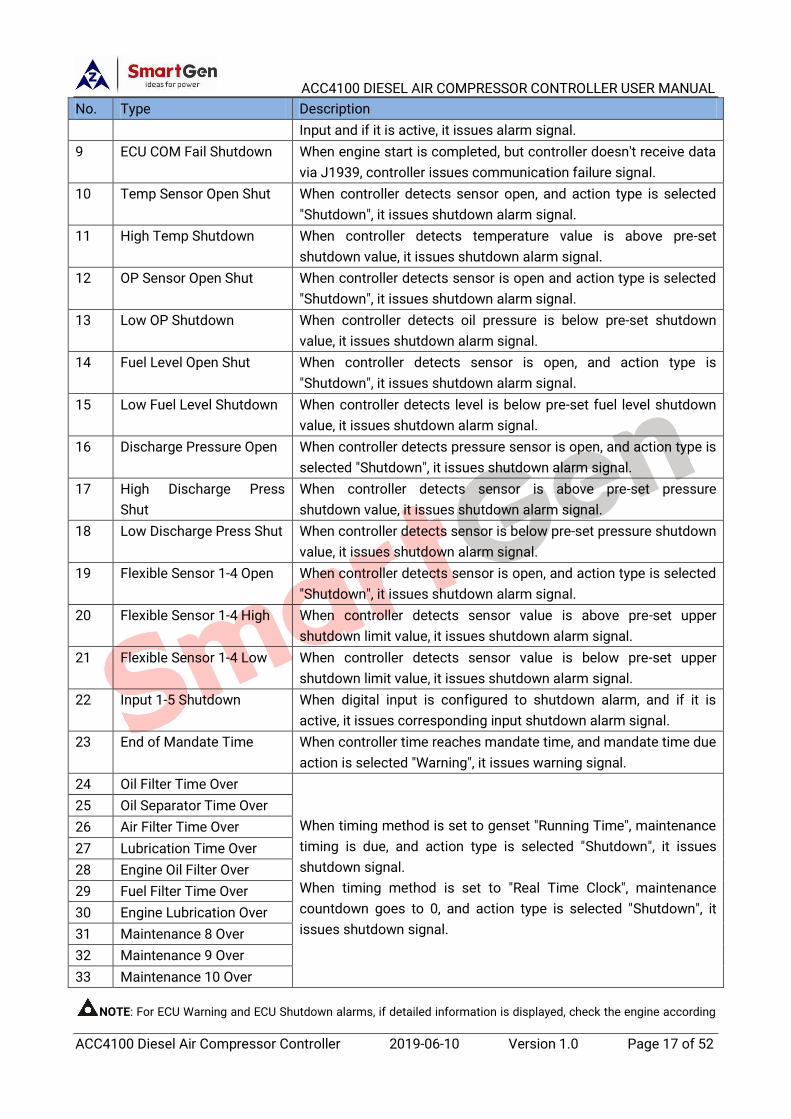
Table 7 Shutdown Alarms
No. Type Description
1 Emergency Stop When controller detects emergency stop alarm signal, it issues
emergency stop alarm signal.
2 Engine Overspeed Shut When controller detects engine speed is over preset over speed
stop threshold, it issues shutdown alarm signal.
3 Engine Underspeed Shut When controller detects engine speed is below preset over speed
stop threshold, it issues shutdown alarm signal.
4 Loss of Speed Signal When controller detects speed is 0, and speed signal loss action is
selected "Shutdown", it issues shutdown alarm signal.
5 Failed to Start When engine fails to start during pre-set start attempts, controller
issues failed to start alarm signal.
6 ECU Shutdown When controller receives shutdown alarm signal via J1939, it
issues shutdown alarm signal.
7 High Temp. Shutdown When controller input port is set to High Temp Shutdown Input and
if it is active, it issues alarm signal.
8 Low Oil Press Shutdown When controller input port is set to Low Oil Pressure Shutdown
ACC4100 DIESEL AIR COMPRESSOR CONTROLLER USER MANUAL
ACC4100 Diesel Air Compressor Controller 2019-06-10 Version 1.0 Page 17 of 52
No. Type Description
Input and if it is active, it issues alarm signal.
9 ECU COM Fail Shutdown When engine start is completed, but controller doesn't receive data
via J1939, controller issues communication failure signal.
10 Temp Sensor Open Shut When controller detects sensor open, and action type is selected
"Shutdown", it issues shutdown alarm signal.
11 High Temp Shutdown When controller detects temperature value is above pre-set
shutdown value, it issues shutdown alarm signal.
12 OP Sensor Open Shut When controller detects sensor is open and action type is selected
"Shutdown", it issues shutdown alarm signal.
13 Low OP Shutdown When controller detects oil pressure is below pre-set shutdown
value, it issues shutdown alarm signal.
14 Fuel Level Open Shut When controller detects sensor is open, and action type is
"Shutdown", it issues shutdown alarm signal.
15 Low Fuel Level Shutdown When controller detects level is below pre-set fuel level shutdown
value, it issues shutdown alarm signal.
16 Discharge Pressure Open When controller detects pressure sensor is open, and action type is
selected "Shutdown", it issues shutdown alarm signal.
17 High Discharge Press
Shut
When controller detects sensor is above pre-set pressure
shutdown value, it issues shutdown alarm signal.
18 Low Discharge Press Shut When controller detects sensor is below pre-set pressure shutdown
value, it issues shutdown alarm signal.
19 Flexible Sensor 1-4 Open When controller detects sensor is open, and action type is selected
"Shutdown", it issues shutdown alarm signal.
20 Flexible Sensor 1-4 High When controller detects sensor value is above pre-set upper
shutdown limit value, it issues shutdown alarm signal.
21 Flexible Sensor 1-4 Low When controller detects sensor value is below pre-set upper
shutdown limit value, it issues shutdown alarm signal.
22 Input 1-5 Shutdown When digital input is configured to shutdown alarm, and if it is
active, it issues corresponding input shutdown alarm signal.
23 End of Mandate Time When controller time reaches mandate time, and mandate time due
action is selected "Warning", it issues warning signal.
24 Oil Filter Time Over
When timing method is set to genset "Running Time", maintenance
timing is due, and action type is selected "Shutdown", it issues
shutdown signal.
When timing method is set to "Real Time Clock", maintenance
countdown goes to 0, and action type is selected "Shutdown", it
issues shutdown signal.
25 Oil Separator Time Over
26 Air Filter Time Over
27 Lubrication Time Over
28 Engine Oil Filter Over
29 Fuel Filter Time Over
30 Engine Lubrication Over
31 Maintenance 8 Over
32 Maintenance 9 Over
33 Maintenance 10 Over
NOTE: For ECU Warning and ECU Shutdown alarms, if detailed information is displayed, check the engine according

ACC4100 DIESEL AIR COMPRESSOR CONTROLLER USER MANUAL
ACC4100 Diesel Air Compressor Controller 2019-06-10 Version 1.0 Page 18 of 52
to the information; Otherwise refer to engine user manual to obtain information according to SPN alarm code.
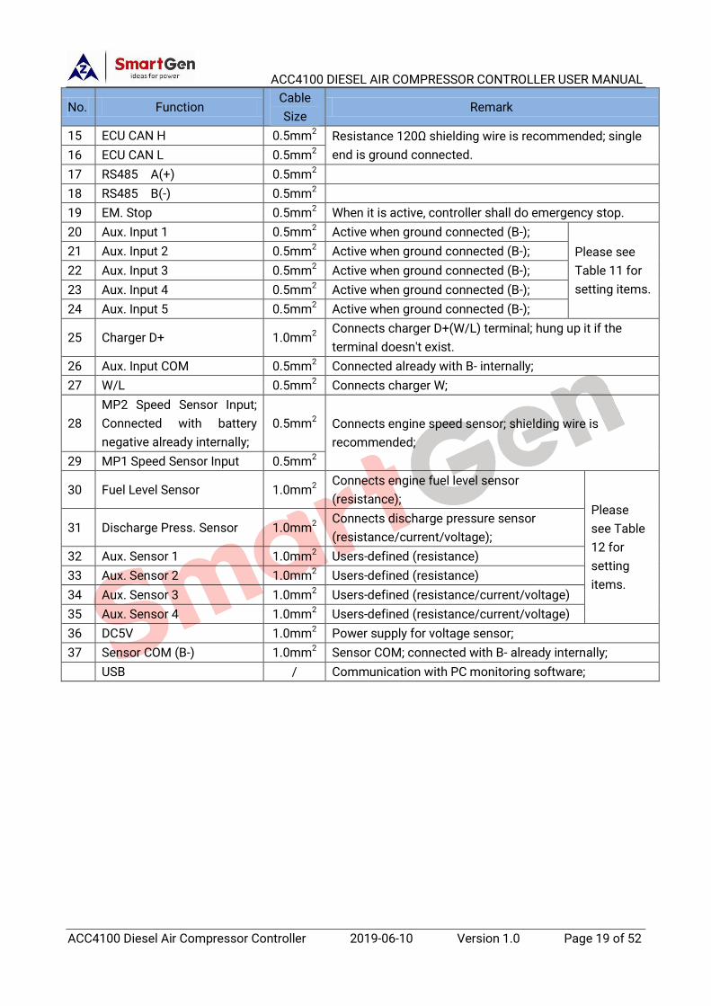
7 WIRE CONNECTION
Fig. 6 Controller Back Panel
Table 8 Connection Terminal Description
No. Function Cable
Size Remark
1 DC Power Input B- 1.5mm2 Connects starter battery negative;
2 DC Power Input B+ 1.5mm2 Connects starter battery positive;
3 COM1 Relay 1.5mm2
Connects COM1 output, Rated 5A DC 28V; 4 Start Relay Output 1.0mm2
5 AUX. Output 1 1.0mm2
6 COM2 Relay 1.0mm2
Connects COM2 output, Rated 1A DC28V; Please
see
Table
10 for
setting
items.
7 AUX. Output 2 1.0mm2
8 AUX. Output 3 1.5mm2
9 AUX. Output 4 1.5mm2
10 AUX. Output 5
1.0mm2 N/O volts free contact, Rated 1A DC 28V;
11 1.0mm2
12
AUX. Output 6
1.0mm2 N/O output, Rated 1A DC28V;
13 1.0mm2 N/C output, Rated 1A DC28V;
14 1.0mm2 Relay COM
ACC4100 DIESEL AIR COMPRESSOR CONTROLLER USER MANUAL
ACC4100 Diesel Air Compressor Controller 2019-06-10 Version 1.0 Page 19 of 52
No. Function Cable
Size Remark
15 ECU CAN H 0.5mm2 Resistance 120Ω shielding wire is recommended; single
end is ground connected. 16 ECU CAN L 0.5mm2
17 RS485 A(+) 0.5mm2
18 RS485 B(-) 0.5mm2
19 EM. Stop 0.5mm2 When it is active, controller shall do emergency stop.
20 Aux. Input 1 0.5mm2 Active when ground connected (B-);
Please see
Table 11 for
setting items.
21 Aux. Input 2 0.5mm2 Active when ground connected (B-);
22 Aux. Input 3 0.5mm2 Active when ground connected (B-);
23 Aux. Input 4 0.5mm2 Active when ground connected (B-);
24 Aux. Input 5 0.5mm2 Active when ground connected (B-);
25 Charger D+ 1.0mm2 Connects charger D+(W/L) terminal; hung up it if the
terminal doesn't exist.
26 Aux. Input COM 0.5mm2 Connected already with B- internally;
27 W/L 0.5mm2 Connects charger W;
28
MP2 Speed Sensor Input;
Connected with battery
negative already internally;
0.5mm2 Connects engine speed sensor; shielding wire is
recommended;
29 MP1 Speed Sensor Input 0.5mm2
30 Fuel Level Sensor 1.0mm2 Connects engine fuel level sensor
(resistance); Please
see Table
12 for
setting
items.
31 Discharge Press. Sensor 1.0mm2 Connects discharge pressure sensor
(resistance/current/voltage);
32 Aux. Sensor 1 1.0mm2 Users-defined (resistance)
33 Aux. Sensor 2 1.0mm2 Users-defined (resistance)
34 Aux. Sensor 3 1.0mm2 Users-defined (resistance/current/voltage)
35 Aux. Sensor 4 1.0mm2 Users-defined (resistance/current/voltage)
36 DC5V 1.0mm2 Power supply for voltage sensor;
37 Sensor COM (B-) 1.0mm2 Sensor COM; connected with B- already internally;
USB / Communication with PC monitoring software;

ACC4100 DIESEL AIR COMPRESSOR CONTROLLER USER MANUAL
ACC4100 Diesel Air Compressor Controller 2019-06-10 Version 1.0 Page 20 of 52
8 CONFIGURATION PARAMETER RANGE AND DEFINITION
8.1 PARAMETER RANGE AND DEFINITION
Table 9 Parameter Setting Contents and Range List
No. Item Range Default Description
Language
1 Language (0-1) 0
0: Simplified Chinese
1: English
Override Mode
1 Override Mode (0-1) 0
0: Disable
1: Enable
LCD Backlight
1 Ratio (0-10) 5 Set LCD contrast ratio;
2 Brightness (0-5) 5 Set LCD backlight brightness;
3 Delay (0-3600)min 5
Backlight is always light on when delay is set
to 0min.
Module Setting
1 Module Address (1-254) 1 Controller address for remote monitoring;
2 Comm. Stop Bit (0-1) 0
0: 2-bit Stop Bit
1: 1-bit Stop Bit (ToolKit SC Settings)
3 Password
(0-9999) 1234
It used for advanced parameter setting;
Caution! Default password is "1234";
It can be changed by operator for purpose of
preventing others changing controller
advanced configuration.
If password is changed, please remember
clearly.
If it is forgot, please contact company
service person;
4 Date and Time Users can calibrate date and time;
5 Maintain Password (0-9999) 1234 Independent password for maintenance;
Timer Setting
1 Preheat Delay (0-3600)s 0
Time for pre-heating plug to be energized
before starter is energized;
2 Prestart Fuel Time (0-3600)s 1
Time for fuel relay output everytime before
starter is energized;
3 Cranking Time (3-60)s 8 Time for starter to be energized every time;
4 Crank Rest Time (3-60)s 10
Waiting time before second energization
when engine fails to start;
5 Safety On Delay
(0-3600)s 10
During this time oil pressure low, temp. high,
under speed, under frequency, under voltage,
and charge alt failure alarms are all inactive;
ACC4100 DIESEL AIR COMPRESSOR CONTROLLER USER MANUAL
ACC4100 Diesel Air Compressor Controller 2019-06-10 Version 1.0 Page 21 of 52
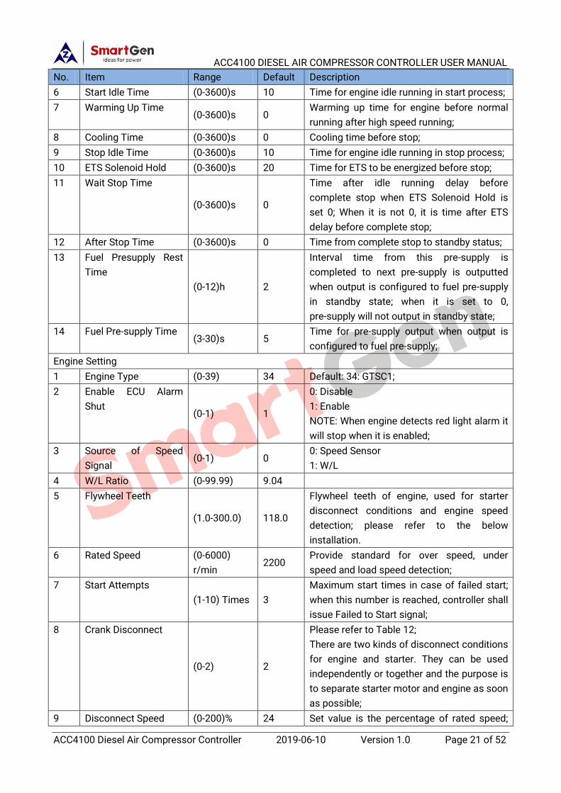
No. Item Range Default Description
6 Start Idle Time (0-3600)s 10 Time for engine idle running in start process;
7 Warming Up Time (0-3600)s 0
Warming up time for engine before normal
running after high speed running;
8 Cooling Time (0-3600)s 0 Cooling time before stop;
9 Stop Idle Time (0-3600)s 10 Time for engine idle running in stop process;
10 ETS Solenoid Hold (0-3600)s 20 Time for ETS to be energized before stop;
11 Wait Stop Time
(0-3600)s 0
Time after idle running delay before
complete stop when ETS Solenoid Hold is
set 0; When it is not 0, it is time after ETS
delay before complete stop;
12 After Stop Time (0-3600)s 0 Time from complete stop to standby status;
13 Fuel Presupply Rest
Time
(0-12)h 2
Interval time from this pre-supply is
completed to next pre-supply is outputted
when output is configured to fuel pre-supply
in standby state; when it is set to 0,
pre-supply will not output in standby state;
14 Fuel Pre-supply Time (3-30)s 5
Time for pre-supply output when output is
configured to fuel pre-supply;
Engine Setting
1 Engine Type (0-39) 34 Default: 34: GTSC1;
2 Enable ECU Alarm
Shut (0-1) 1
0: Disable
1: Enable
NOTE: When engine detects red light alarm it
will stop when it is enabled;
3 Source of Speed
Signal (0-1) 0
0: Speed Sensor
1: W/L
4 W/L Ratio (0-99.99) 9.04
5 Flywheel Teeth
(1.0-300.0) 118.0
Flywheel teeth of engine, used for starter
disconnect conditions and engine speed
detection; please refer to the below
installation.
6 Rated Speed (0-6000)
r/min 2200
Provide standard for over speed, under
speed and load speed detection;
7 Start Attempts
(1-10) Times 3
Maximum start times in case of failed start;
when this number is reached, controller shall
issue Failed to Start signal;
8 Crank Disconnect
(0-2) 2
Please refer to Table 12;
There are two kinds of disconnect conditions
for engine and starter. They can be used
independently or together and the purpose is
to separate starter motor and engine as soon
as possible;
9 Disconnect Speed (0-200)% 24 Set value is the percentage of rated speed;

ACC4100 DIESEL AIR COMPRESSOR CONTROLLER USER MANUAL
ACC4100 Diesel Air Compressor Controller 2019-06-10 Version 1.0 Page 22 of 52
No. Item Range Default Description
when speed is above the set value, starter
shall disconnect; Please refer to the rear
installation.
10 Disconnect OP
(0-1000)kPa 200
When OP is above pre-set value, starter shall
disconnect. Please refer to the rear
installation.
11 Overspeed
Warn
Set (0-200.0)% 110.0 Set value is the percentage of rated speed;
Return value and delay value can also be set. Return (0-200.0)% 108.0
Delay (0-3600)s 5
12 Underspeed
Warn
Set (0-200.0)% 55.0
Return (0-200.0)% 60.0
Delay (0-3600)s 5
13 Overspeed
Shutdown
Set (0-200.0)% 114.0 Set value is the percentage of rated speed;
Delay value can also be set. Delay (0-3600)s 2
14 Underspeed
Shutdown
Set (0-200.0)% 50.0
Delay (0-3600)s 3
15 Loss of Speed Signal
Delay (0-3600)s 5
Time from detecting speed is 0 to confirm
the action;
16 Loss of Speed Signal
Action (0-1) 0
0: Warning
1: Shutdown
17 Battery Rated Voltage (0-60.0)V 24.0
Provide standard for battery over/under
voltage detection;
18 Battery
Overvolt
Warn
Set (0-200)% 120 Set value is the percentage of battery rated
voltage;
Return value and delay value can also be set.
Return (0-200)% 115
Delay (0-3600)s 60
19 Battery
Undervolt
Warn
Set (0-200)% 85
Return (0-200)% 90
Delay (0-3600)s 60
20 Charge Alt
Fail
Set (0-60.0)V 8.0 During engine normal running process, when
charger D+ voltage is below this value,
controller issues charge alt fail warning.
Return (0-60.0)V 10.0
Delay (0-3600)s 10
21 Engine Idle Speed
(0-100)% 70
Set value is the percentage of rated speed;
when idle running is needed, make the speed
steady at the set value;
22 Engine Unload Speed
(0-100)% 70
Set value is the percentage of rated speed;
when discharge pressure reaches rated
pressure after load, make speed steady at
the set value;
23 Air Com. Rated
Pressure (0-30000)kPa 700
Adjust speed at corresponding upper limit
pressure value after load;
24 Air Com. Unload Act
Press (0-30000)kPa 600
Adjust speed at corresponding lower limit
pressure value after load;
25 Raise Speed Rate Set (30-500)r/s 150 Increased number of turns per second;
ACC4100 DIESEL AIR COMPRESSOR CONTROLLER USER MANUAL
ACC4100 Diesel Air Compressor Controller 2019-06-10 Version 1.0 Page 23 of 52
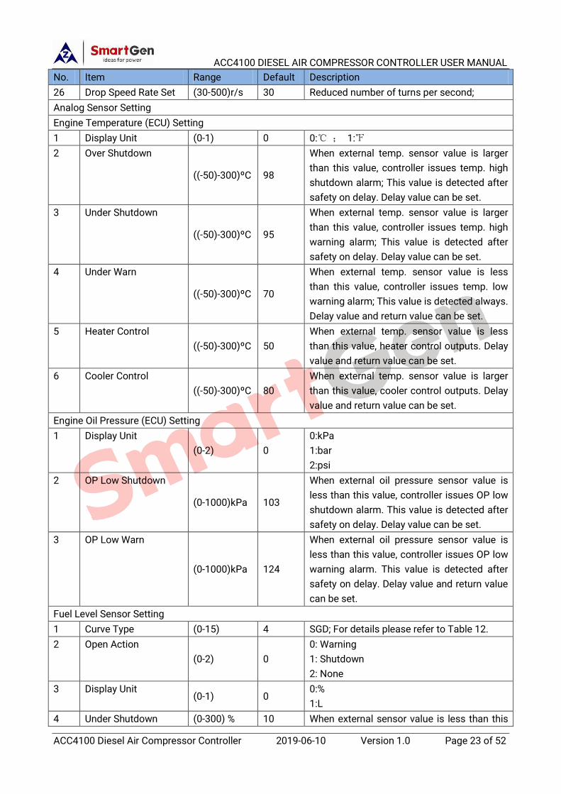
No. Item Range Default Description
26 Drop Speed Rate Set (30-500)r/s 30 Reduced number of turns per second;
Analog Sensor Setting
Engine Temperature (ECU) Setting
1 Display Unit (0-1) 0 0:℃ ; 1:℉
2 Over Shutdown
((-50)-300)ºC 98
When external temp. sensor value is larger
than this value, controller issues temp. high
shutdown alarm; This value is detected after
safety on delay. Delay value can be set.
3 Under Shutdown
((-50)-300)ºC 95
When external temp. sensor value is larger
than this value, controller issues temp. high
warning alarm; This value is detected after
safety on delay. Delay value can be set.
4 Under Warn
((-50)-300)ºC 70
When external temp. sensor value is less
than this value, controller issues temp. low
warning alarm; This value is detected always.
Delay value and return value can be set.
5 Heater Control
((-50)-300)ºC 50
When external temp. sensor value is less
than this value, heater control outputs. Delay
value and return value can be set.
6 Cooler Control
((-50)-300)ºC 80
When external temp. sensor value is larger
than this value, cooler control outputs. Delay
value and return value can be set.
Engine Oil Pressure (ECU) Setting
1 Display Unit
(0-2) 0
0:kPa
1:bar
2:psi
2 OP Low Shutdown
(0-1000)kPa 103
When external oil pressure sensor value is
less than this value, controller issues OP low
shutdown alarm. This value is detected after
safety on delay. Delay value can be set.
3 OP Low Warn
(0-1000)kPa 124
When external oil pressure sensor value is
less than this value, controller issues OP low
warning alarm. This value is detected after
safety on delay. Delay value and return value
can be set.
Fuel Level Sensor Setting
1 Curve Type (0-15) 4 SGD; For details please refer to Table 12.
2 Open Action
(0-2) 0
0: Warning
1: Shutdown
2: None
3 Display Unit (0-1) 0
0:%
1:L
4 Under Shutdown (0-300) % 10 When external sensor value is less than this

ACC4100 DIESEL AIR COMPRESSOR CONTROLLER USER MANUAL
ACC4100 Diesel Air Compressor Controller 2019-06-10 Version 1.0 Page 24 of 52
No. Item Range Default Description
value, controller issues shutdown alarm;
Alarm enable and delay value can be set.
5 Under Warn
(0-300) % 20
When external sensor value is less than this
value, controller issues warning alarm; Alarm
enable, return and delay value can be set.
6 Fuel Pump Control
(0-300)% 10
When external fuel level sensor value is less
than this value, fuel pump control outputs;
Return and delay values can be set;
7 Fuel Tank Capacity
Set (0-10000)L 1000
8 Custom Curve When custom curve (resistance) is selected,
related curve shall be set.
Discharge Pressure Sensor Setting
1 Curve Type (0-15) 2
Custom 4-20mA curve;
Please refer to Table 12 for details.
2 Open Action
(0-2) 0
0: Warning
1: Shutdown
2: None
3 Display Unit
(0-2) 0
0:kPa
1:bar
2:psi
4 Over Shutdown (0-30000)
kPa 6000
When external sensor value is larger than
this value, controller issues shutdown alarm;
Alarm enable and delay value can be set.
5 Under Shutdown (0-30000)
kPa 100
When external sensor value is less than this
value, controller issues shutdown alarm;
alarm enable and delay value can be set.
6 Over Warn
(0-30000)
kPa 5000
When external sensor value is larger than
this value, controller issues warning alarm;
alarm enable, return and delay values can be
set.
7 Under Warn (0-30000)
kPa 200
When external sensor value is less than this
value, controller issues warning alarm; alarm
enable, return and delay values can be set.
8 Custom Curve When custom resistance/current/voltage
types are selected; related curve needs to be
set.
Flexible Sensor 1-4 Setting
1 Sensor Type
(0-5) 0
0: Not Used
1: Engine Temperature Sensor
2: Engine Oil Pressure Sensor
3: Temperature Sensor
4: Oil Pressure Sensor
ACC4100 DIESEL AIR COMPRESSOR CONTROLLER USER MANUAL
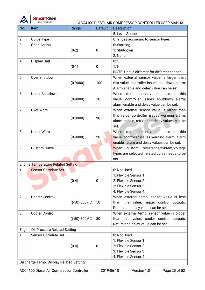
ACC4100 Diesel Air Compressor Controller 2019-06-10 Version 1.0 Page 25 of 52
No. Item Range Default Description
5: Level Sensor
2 Curve Type Changes according to sensor types;
3 Open Action
(0-2) 0
0: Warning
1: Shutdown
2: None
4 Display Unit
(0-1) 0
0:℃
1:℉
NOTE: Unit is different for different sensor.
5 Over Shutdown
(0-9000) 100
When external sensor value is larger than
this value, controller issues shutdown alarm;
Alarm enable and delay value can be set.
6 Under Shutdown
(0-9000) 10
When external sensor value is less than this
value, controller issues shutdown alarm;
alarm enable and delay value can be set.
7 Over Warn
(0-9000) 90
When external sensor value is larger than
this value, controller issues warning alarm;
alarm enable, return and delay values can be
set.
8 Under Warn
(0-9000) 20
When external sensor value is less than this
value, controller issues warning alarm; alarm
enable, return and delay values can be set.
9 Custom Curve When custom resistance/current/voltage
types are selected; related curve needs to be
set.
Engine Temperature Related Setting
1 Sensor Correlate Set
(0-4) 0
0: Not Used
1: Flexible Sensor 1
2: Flexible Sensor 2
3: Flexible Sensor 3
4: Flexible Sensor 4
2 Heater Control
((-50)-300)ºC 50
When external temp. sensor value is less
than this value, heater control outputs;
Return and delay value can be set.
3 Cooler Control
((-50)-300)ºC 80
When external temp. sensor value is bigger
than this value, cooler control outputs;
Return and delay value can be set.
Engine Oil Pressure Related Setting
1 Sensor Correlate Set
(0-4) 0
0: Not Used
1: Flexible Sensor 1
2: Flexible Sensor 2
3: Flexible Sensor 3
4: Flexible Sensor 4
Discharge Temp. Display Related Setting

ACC4100 DIESEL AIR COMPRESSOR CONTROLLER USER MANUAL
ACC4100 Diesel Air Compressor Controller 2019-06-10 Version 1.0 Page 26 of 52
No. Item Range Default Description
1 Sensor Correlate Set
(0-4) 0
0: Not Used
1: Flexible Sensor 1
2: Flexible Sensor 2
3: Flexible Sensor 3
4: Flexible Sensor 4
Digital Input Ports
Digital Input 1
1 Contents Setting (0-53) 3
Alarm Reset; Please refer to Table 11 for
details.
2 Active Type (0-1) 0
0: Close
1: Open
Digital Input 2
1 Contents Setting (0-53) 26
High Temp. Shutdown Input;
Please refer to Table 11 for details.
2 Active Type (0-1) 0
0: Close
1: Open
Digital Input 3
1 Contents Setting (0-53) 27
Low Oil Pressure Shutdown Input;
Please refer to Table 11 for details.
2 Active Type (0-1) 0
0: Close
1: Open
Digital Input 4
1 Contents Setting (0-53) 0
Users defined;
Please refer to Table 11 for details.
2 Active Type (0-1) 0
0: Close
1: Open
3 Active Range
(0-3) 2
0: From Safety On
1: From Crank
2: Always
3: Never
4 Active Action
(0-2) 1
0: Warning
1: Shutdown
2: Indication
5 Active Delay (0-20.0)s 2.0
Time from detecting input is active to
confirm;
6 Input Description Users defined;
Digital Input 5
1 Contents Setting (0-53) 0
Users defined;
Please refer to Table 11 for details.
2 Active Type (0-1) 0
0: Close
1: Open
3 Active Range (0-3) 2
0: From Safety On
1: From Crank

ACC4100 DIESEL AIR COMPRESSOR CONTROLLER USER MANUAL
ACC4100 Diesel Air Compressor Controller 2019-06-10 Version 1.0 Page 27 of 52
No. Item Range Default Description
2: Always
3: Never
4 Active Action
(0-2) 1
0: Warning
1: Shutdown
2: Indication
5 Active Delay (0-20.0)s 2.0
Time from detecting input is active to
confirm;
6 Input Description (0-53) 0 Users defined;
Auxiliary Output
Auxiliary Output 1
1 Contents Setting (0-119) 29
Fuel relay output;
Please refer to Table 10 for details.
2 Output Type (0-1) 0
0: Normally Open
1: Normally Close
Auxiliary Output 2
1 Contents Setting (0-119) 28
Start relay output;
Please refer to Table 10 for details.
2 Output Type (0-1) 0
0: Normally Open
1: Normally Close
Auxiliary Output 3
1 Contents Setting (0-119) 30
Idle speed control;
Please refer to Table 10 for details.
2 Output Type (0-1) 0
0: Normally Open
1: Normally Close
Auxiliary Output 4
1 Contents Setting (0-119) 26
Load control;
Please refer to Table 10 for details.
2 Output Type (0-1) 0
0: Normally Open
1: Normally Close
Auxiliary Output 5
1 Contents Setting (0-119) 39
Normal running output;
Please refer to Table 10 for details.
2 Output Type (0-1) 0
0: Normally Open
1: Normally Close
Auxiliary Output 6
1 Contents Setting (0-119) 42
Common alarm;
Please refer to Table 10 for details.
2 Output Type (0-1) 0
0: Normally Open
1: Normally Close
Alternate Configuration Setting
Alternate Configuration 1
1 Enable Choose (0-1) 0
0: Disable
1: Enable

ACC4100 DIESEL AIR COMPRESSOR CONTROLLER USER MANUAL
ACC4100 Diesel Air Compressor Controller 2019-06-10 Version 1.0 Page 28 of 52
No. Item Range Default Description
2 Engine Rated Speed (0-6000)
r/min 2200
When this is enabled, if input is configured to
"Alt Config. 1 Active", and if input is active,
speed shall be adjusted according to
alternate configuration settings after load.
3 Engine Unload Speed (0-100)% 70
4 Air Com. Rated
Pressure (0-30000)kPa 700
5 Air Com. Unload Act
Press (0-30000)kPa 600
Alternate Configuration 2
1 Enable Choose (0-1) 0
0: Disable
1: Enable
2 Engine Rated Speed (0-6000)
r/min 2200
When this is enabled, if input is configured to
"Alt Config. 2 Active", and if input is active,
speed shall be adjusted according to
alternate configuration settings after load.
3 Engine Unload Speed (0-100)% 70
4 Air Com. Rated
Pressure (0-30000)kPa 700
5 Air Com. Unload Act
Press (0-30000)kPa 600
Alternate Configuration 3
1 Enable Choose (0-1) 0
0: Disable
1: Enable
2 Engine Rated Speed (0-6000)
r/min 2200
When this is enabled, if input is configured to
"Alt Config. 3 Active", and if input is active,
speed shall be adjusted according to
alternate configuration settings after load.
3 Engine Unload Speed (0-100)% 70
4 Air Com. Rated
Pressure (0-30000)kPa 700
5 Air Com. Unload Act
Press (0-30000)kPa 600
Maintenance Setting
1 Oil Filter Set (0-1) 0 0: Disable
1: Enable
Maintenance time, maintenance time due
action, maintenance timing method,
maintenance time reset can also be set at
the same time;
After maintenance, maintenance time due
alarm can be removed by resetting
maintenance time;
Please refer to Table 14 for details.
2 Oil Separator Set (0-1) 0
3 Air Filter Set (0-1) 0
4 Lubrication Set (0-1) 0
5 Engine Oil Filter Set (0-1) 0
6 Engine Fuel Filter Set (0-1) 0
7 Engine Lubrication
Set (0-1) 0
8 Maintenance 8 Set (0-1) 0
9 Maintenance 9 Set (0-1) 0
10 Maintenance 10 Set (0-1) 0
NOTES:
— Regarding parameter setting on PC software, it isn't needed to input default factory password "1234" if it is not
changed; if password is changed, and it is the first time to do configuration on PC, then it is needed to input
password in password screen.

ACC4100 DIESEL AIR COMPRESSOR CONTROLLER USER MANUAL
ACC4100 Diesel Air Compressor Controller 2019-06-10 Version 1.0 Page 29 of 52
— Digital input ports cannot be set the same items, otherwise function shall not work correctly; Output ports can be
set the same item.
— Engine temperature related settings: if it is ordinary engine and engine temperature is needed, then any one of
flexible sensors 1-4 shall be set engine temperature sensor; and at the same time curve type shall be set the
corresponding one; Next is to set engine temperature related sensor; Select corresponding flexible sensor, which is
engine temperature sensor at this time, heater control and cooler control can be realized. if alarm output function
will be set, corresponding flexible sensor output shall be set.
— Engine oil pressure related settings: if it is ordinary engine and it is needed to use engine oil pressure to judge crank
disconnect, any one of the flexible sensors 1-4 shall be set engine oil pressure, meanwhile curve type shall be set to
the corresponding one. Then set engine oil pressure related sensor; Choose corresponding sensor, and at this time
oil pressure is displayed, which can be one of the crank disconnect conditions; If alarm output function will be set,
corresponding flexible sensor output shall be set.
— Discharge temperature display related settings: if discharge temperature is needed to display in the first page of
main screen, then any one of the flexible sensors 1-4 shall be set temperature, and at the same time curve type
shall be set corresponding curve; Then set discharge temperature display related setting; Choose corresponding
sensor, and at this time first page shall have discharge temperature. If alarm output function will be set,
corresponding flexible sensor output shall be set.
8.2 DEFINABLE CONTENTS OF FLEXIBLE OUTPUT PORTS 1-6
Table 10 Definable Contents of Flexible Output Ports 1-6
No. Type Function Description
0 Not Used
1 Custom Period 1 Please refer to the following contents for function details.
2 Custom Period 2
3 Custom Period 3
4 Custom Period 4
5 Custom Period 5
6 Custom Period 6
7 Custom Combined 1
8 Custom Combined 2
9 Custom Combined 3
10 Custom Combined 4
11 Custom Combined 5
12 Custom Combined 6
13 Reserved
14 Reserved
15 Air Flap Control Act at the time of over speed shutdown alarm and emergency
stop; Air flap can be closed to realize fast stop.
16 Audible Alarm Act at the time of warning and shutdown alarms; Announciator
can be connected externally; It can be inhibited to output when
input port "Alarm Mute" is active or any button is pressed; When
there is new warning or shutdown alarm, it outputs again.
17 Louver Control Act at the time of engine start; Disconnect after engine stop.

ACC4100 DIESEL AIR COMPRESSOR CONTROLLER USER MANUAL
ACC4100 Diesel Air Compressor Controller 2019-06-10 Version 1.0 Page 30 of 52
No. Type Function Description
18 Fuel Pump Control Act by fuel level sensor of fuel pump controlling the upper and
lower limits;
19 Heater Control Act by temp. sensor of heater control controlling the upper and
lower limits;
20 Cooler Control Act by temp. sensor of cooler control controlling the upper and
lower limits;
21 Fuel Pre-supply Under standby state, fuel pre-supply output port is active and it
outputs circularly according to pre-set "Fuel Pre-supply Rest
Time" and "Fuel Pre-supply Time"; If "Fuel Pre-supply Rest Time" is
0h, then it doesn't output;
Before start, pre-set pre-supply time is outputted; If pre-heat time
is not configured, pre-supply outputs; If pre-heat time is
configured, then pre-heat phase outputs;
22 Reserved
23 Pre-lubricate Act at the phase of pre-heating, fuel, start, and start rest time;
24 Remote Control Controlled by communication port RS485;
25 Reserved
26 Load Control Load/Unload button is pressed or load control input is active, then
load control outputs; If load/unload button is pressed again or
load input is inactive, then load control stops outputting.
27 Reserved
28 Start Relay Act at engine start; and disconnect after successful start;
29 Fuel Relay Act at engine start; and disconnect at ETS stop;
30 Idle Control Used for engine with idle speed; Pull in before start, and
disconnect at entering warming up time; Pull in at the process of
stop idle speed, and disconnect when engine stops completely.
31 Speed Raise Output Act in warming up period, and controlled by speed regulator in
normal running period.
32 Speed Drop Output Act from stop idle speed to waiting for stop period and controlled
by speed regulator in normal running period.
33 Energise to Stop Used for engine with stop ETS; Pull in when stop idle speed is
over, and disconnect when pre-set "ETS Solenoid Hold" is over.
34 Run Key Switch Control Used for checking ECU data once at power on; it outputs once it is
power on; it stops outputting the signal at ETS stop time and
failed to stop time;
35 ECU Stop Applicable for engine supporting ECU, and used to control ECU
stop;
36 ECU Power Supply Applicable for engine supporting ECU, and used to control ECU
power;
37 Reserved
38 Crank Success Pull in when it detects crank success signal;
39 Normal Running Pull in and output when it is in normal running period;
40 Reserved
ACC4100 DIESEL AIR COMPRESSOR CONTROLLER USER MANUAL
ACC4100 Diesel Air Compressor Controller 2019-06-10 Version 1.0 Page 31 of 52
No. Type Function Description
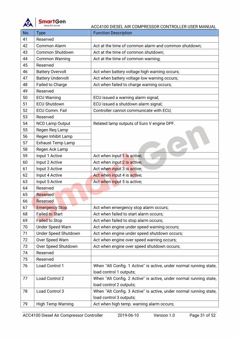
41 Reserved
42 Common Alarm Act at the time of common alarm and common shutdown;
43 Common Shutdown Act at the time of common shutdown;
44 Common Warning Act at the time of common warning;
45 Reserved
46 Battery Overvolt Act when battery voltage high warning occurs;
47 Battery Undervolt Act when battery voltage low warning occurs;
48 Failed to Charge Act when failed to charge warning occurs;
49 Reserved
50 ECU Warning ECU issued a warning alarm signal;
51 ECU Shutdown ECU issued a shutdown alarm signal;
52 ECU Comm. Fail Controller cannot communicate with ECU;
53 Reserved
54 NCD Lamp Output Related lamp outputs of Euro V engine DPF.
55 Regen Req Lamp
56 Regen Inhibit Lamp
57 Exhaust Temp Lamp
58 Regen Ack Lamp
59 Input 1 Active Act when input 1 is active;
60 Input 2 Active Act when input 2 is active;
61 Input 3 Active Act when input 3 is active;
62 Input 4 Active Act when input 4 is active;
63 Input 5 Active Act when input 5 is active;
64 Reserved
65 Reserved
66 Reserved
67 Emergency Stop Act when emergency stop alarm occurs;
68 Failed to Start Act when failed to start alarm occurs;
69 Failed to Stop Act when failed to stop alarm occurs;
70 Under Speed Warn Act when engine under speed warning occurs;
71 Under Speed Shutdown Act when engine under speed shutdown occurs;
72 Over Speed Warn Act when engine over speed warning occurs;
73 Over Speed Shutdown Act when engine over speed shutdown occurs;
74 Reserved
75 Reserved
76 Load Control 1 When "Alt Config. 1 Active" is active, under normal running state,
load control 1 outputs;
77 Load Control 2 When "Alt Config. 2 Active" is active, under normal running state,
load control 2 outputs;
78 Load Control 3 When "Alt Config. 3 Active" is active, under normal running state,
load control 3 outputs;
79 High Temp Warning Act when high temp. warning alarm occurs;

ACC4100 DIESEL AIR COMPRESSOR CONTROLLER USER MANUAL
ACC4100 Diesel Air Compressor Controller 2019-06-10 Version 1.0 Page 32 of 52
No. Type Function Description
80 Low Temp Warning Act when low temp. warning alarm occurs;
81 High Temp Shutdown Act when high temp. shutdown alarm occurs;
82 Reserved
83 Engine Low OP Warn Act when low oil pressure warning occurs;
84 Engine Low OP Shut Act when low oil pressure shutdown occurs;
85 Reserved
86 Reserved
87 Reserved
88 Low Fuel Level Warn Act when low fuel level warning occurs;
89 Reserved
90 Low Fuel Level Shut Act when low fuel level shutdown occurs;
91 Reserved
92 Reserved
93 High DP Warn Act when discharge pressure high warning occurs;
94 Low DP Warn Act when discharge pressure low warning occurs;
95 High DP Shut Act when discharge pressure high shutdown occurs;
96 Low DP Shut Act when discharge pressure low shutdown occurs;
97 Sensor 1 High Warn Act when sensor 1 high warning occurs;
98 Sensor 1 Low Warn Act when sensor 1 low warning occurs;
99 Sensor 1 High Shut Act when sensor 1 high shutdown occurs;
100 Sensor 1 Low Shut Act when sensor 1 low shutdown occurs;
101 Sensor 2 High Warn Act when sensor 2 high warning occurs;
102 Sensor 2 Low Warn Act when sensor 2 low warning occurs;
103 Sensor 2 High Shut Act when sensor 2 high shutdown occurs;
104 Sensor 2 Low Shut Act when sensor 2 low shutdown occurs;
105 Sensor 3 High Warn Act when sensor 3 high warning occurs;
106 Sensor 3 Low Warn Act when sensor 3 low warning occurs;
107 Sensor 3 High Shut Act when sensor 3 high shutdown occurs;
108 Sensor 3 Low Shut Act when sensor 3 low shutdown occurs;
109 Sensor 4 High Warn Act when sensor 4 high warning occurs;
110 Sensor 4 Low Warn Act when sensor 4 low warning occurs;
111 Sensor 4 High Shut Act when sensor 4 high shutdown occurs;
112 Sensor 4 Low Shut Act when sensor 4 low shutdown occurs;
113 Reserved
114 Reserved
115 Reserved
116 Reserved
117 Reserved
118 Reserved
119 Reserved

ACC4100 DIESEL AIR COMPRESSOR CONTROLLER USER MANUAL
ACC4100 Diesel Air Compressor Controller 2019-06-10 Version 1.0 Page 33 of 52
8.2.1 CUSTOM PERIOD OUTPUT
Defined period output is composed by 2 parts: period output S1 and condition output S2.
S1 and S2 both are true, then it outputs; S1 or S2 is false, it doesn't output;
Period output S1 can be configured randomly to one , or several period outputs; Delay time and
output time can be set after entering period;
Condition output S2 can be any contents of output settings.
NOTE: When period output S1 delay time and output time are both 0, configurations of period output S1 are both true.
Output period: Start
Delay output time: 2s
Output time: 3s
Condition output contents: Input 1 is active;
Condition output active/inactive close; close when active (disconnect when inactive)
When input port 1 is active, and it enters start time and delays for 2s, custom period output starts
to output, after outputting for 3s, it stops outputting;
When input port 1 is inactive, custom output doesn't output.
8.2.2 DEFINED COMBINATION OUTPUT
Defined combination output is composed by 3 parts: conditional output S1, conditional output S2,
and conditional output S3.
S1 or S2 is true, and S3 is true, then combination output outputs.
S1 and S2 both are false, or S3 is false, then combination output doesn't output.
NOTE: S1, S2 and S3 can be any contents except itself defined combination output of the output settings.
NOTE: S1, S2 and S3 cannot include or recursively include itself.
Contents of OR condition output S1: output port 1 is active;
Close when OR condition output S1 is active/inactive: close when active (disconnect when
inactive);
Contents of OR condition output S2, output port 2 is active;
Close when OR condition output S2 is active/inactive: close when active (disconnect when
inactive);
Contents of AND condition output S3: output port 3 is active;
Close when AND condition output S3 is active/inactive: close when active (disconnect when
inactive);
When input port 1 is active or input port 2 is active, if input port 3 is active, defined combination
output is outputting; If input port 3 is inactive, defined combination output is not outputting;
When input port 1 is inactive and port 2 is inactive, no matter port 3 is active or not, defined
combination output is not outputting.

ACC4100 DIESEL AIR COMPRESSOR CONTROLLER USER MANUAL
ACC4100 Diesel Air Compressor Controller 2019-06-10 Version 1.0 Page 34 of 52
8.3 DEFINED CONTENTS OF CONFIFURABLE INPUT PORTS
Table 11 Definition Contents of Programmable Input Ports
No. Type Description
0 Users Configured
Users can define the following functions:
Indication: indicate only, not warning or shutdown.
Warning: warning only, not shutdown.
Shutdown: alarm and shutdown immediately
Never: input is inactive.
Always: input is active all the time.
From crank: start to detect at the time of start.
From safety on: start to detect after safety on run delay.
1 Reserved
2 Alarm Mute Can prohibit “Audible Alarm” output when input is active.
3 Alarm Reset Can reset shutdown alarm when input is active.
4 Reserved
5 Lamp Test All LED indicators are illuminating when input is active.
6 Panel Lock
All buttons in panel is inactive except
UP/DOWN/CONFIRM buttons. Parameters cannot be
configured. But users can set language, check event log
and controller information. There is in the bottom
right corner on LCD when input is active.
7 Crank Success Input
When this function is active, it means the engine is
started successfully. If this function is configured, the
speed and oil pressure start success conditions will be
invalid.
8 Reserved
9 Reserved
10 Reserved
11 Reserved
12 Reserved
13 Reserved
14 Reserved
15 Reserved
16 DPF Manual Request
A button can be connected externally (not self-lock); For
engine with Euro V standard, if PDF regeneration is
needed, press the button and controller shall issue
manual request command to ECU.
17 DPF Inhibit
For engine with Euro V standard, if DPF Inhibit is needed,
so when input is active, controller issues inhibition
command to ECU.
18 Reserved
19 Reserved
20 Reserved

ACC4100 DIESEL AIR COMPRESSOR CONTROLLER USER MANUAL
ACC4100 Diesel Air Compressor Controller 2019-06-10 Version 1.0 Page 35 of 52
No. Type Description
21 Alarm Stop Inhibit All shutdown alarms are inhibited except emergency
stop and over speed shutdown.(Override mode)
22 Instrument Mode All outputs are inhibited in this mode.
23 Reserved
24 Reset Maintenance Controller will set maintenance time and date as default
when input is active.
25 External Charge Fail When input is active, failed to charge warning alarm
occurs.
26 High Temp Shutdown Connects to sensor digital input.
27 Low OP Shutdown Connects to sensor digital input.
28 Reserved
29 Reserved
30 Reserved
31 Reserved
32 Manual Start Input
When input is active, engine can be started
automatically; when input is inactive, engine can be
stopped automatically.
33 Reserved
34 Simulate Stop key
An external button (unlatched) can be connected and
pressed as simulate panel.
35 Simulate Load/Unload key
36 Reserved
37 Simulate Start key
38 Reserved
39 Reserved
40 Reserved
41 Reserved
42 Alt Config. 1 Active When input port is active, configuration is active;
Different parameters can be set for it, making
convenience for users to choose current configuration
by input port.
43 Alt Config. 2 Active
44 Alt Config. 3 Active
45 Reserved
46 Reserved
47 Load Input
Act between start idle speed and stop idle speed; When
it is active, load control outputs; When it is inactive, load
control stops outputting.
48-53 Reserved

ACC4100 DIESEL AIR COMPRESSOR CONTROLLER USER MANUAL
ACC4100 Diesel Air Compressor Controller 2019-06-10 Version 1.0 Page 36 of 52
8.4 SELECTION OF SENSORS
Table 12 Sensors Selection
No. Description Remark
1 Temperature Sensor
0 Not used
1 Custom Res Curve
2 Custom (4-20)mA Curve
3 Custom Volt Curve
4 VDO
5 CURTIS
6 VOLVO-EC
7 DATCON
8 SGX
9 SGD
10 SGH
11 PT100
12 Cu50
13-15 Reserved
Defined resistance’s
range is (0~1)KΩ, default
is Not Used; Users can
select corresponding
curve by themselves;
If pre-set sensor channel
doesn't support current,
and voltage type, then
curve type item 2 and 3
display "Reserved".
2 Pressure Sensor
0 Not used
1 Custom Res Curve
2 Custom (4-20)mA Curve
3 Custom Volt Curve
4 VDO 10bar
5 CURTIS
6 VOLVO-EC
7 DATCON 10bar
8 SGX
9 SGD
10 SGH
11 -15 Reserved
Defined resistance’s
range is (0~1)KΩ, default
is Not Used; Users can
select corresponding
curve by themselves;
If pre-set sensor channel
doesn't support current,
and voltage type, then
curve type item 2 and 3
display "Reserved".
3 Fuel Level Sensor
0 Not used
1 Custom Res Curve
2 Custom (4-20)mA Curve
3 Custom Volt Curve
4 SGD
5 SGH
6 -15 Reserved
Defined resistance’s
range is (0~1)KΩ, default
is Not Used; Users can
select corresponding
curve by themselves;
If pre-set sensor channel
doesn't support current,
and voltage type, then
curve type item 2 and 3
display "Reserved".

ACC4100 DIESEL AIR COMPRESSOR CONTROLLER USER MANUAL
ACC4100 Diesel Air Compressor Controller 2019-06-10 Version 1.0 Page 37 of 52
8.5 CONDITIONS OF CRANK DISCONNECT SELECTION
Table 13 Crank Disconnect Conditions
No. Setting description
0 Engine Speed
1 Oil pressure
2 Oil pressure + Engine Speed
NOTES:
─ There are 3 conditions to make starter disconnected with engine. Engine speed and oil pressure can be used
separately. We recommend that oil pressure should be used with speed sensor together, in order to make the starter
motor separate with engine immediately and can check crank disconnect exactly.
─ Speed sensor is the magnetic equipment installed in starter for detecting flywheel teeth.
─ When set it speed sensor, users must ensure that the number of flywheel teeth is the same as settings, otherwise,
“over speed shutdown” or “under speed shutdown” may be caused.
─ If genset doesn't have speed sensor please don’t select corresponding items, otherwise, “start fail” or “loss speed
signal” may be caused.
─ If genset doesn't have oil pressure sensor, please don’t select corresponding items.
8.6 MAINTENANCE SETTING
Table 14 Maintenance Setting
Item Content Description
Enable Choose 0: Disabled, 1: Enabled Set maintenance function active or not;
Maintenance Time (0-30000)h
It is the number of hours from the time the
maintenance is enabled to when
maintenance is required.
Maintenance Due
Action
0: No Action;
1: Warning;
2: Shutdown;
3: Indication.
Alarm action when maintenance left time is 0.
Maintain Clock 0: Running Time
1: Real Time Clock The timing of maintenance.
Reset Maintenance After maintenance completion, through this
item reset maintenance time.
Maintenance
Description
Users can set maintenance description name
for maintenance 8, 9 and 10, like Change
Engine Oil.

ACC4100 DIESEL AIR COMPRESSOR CONTROLLER USER MANUAL
ACC4100 Diesel Air Compressor Controller 2019-06-10 Version 1.0 Page 38 of 52
9 PARAMETERS SETTING
Press key and enter into setting menu after controller is power on. The menu list is as
below:
>Return
>Parameters Set
> Override Mode
>DPF Regeneration
>Language
>LCD Backlight
>Event Log
>Module Info
Select “Parameters Set” and input correct password (default: 0318) to enter setting interface.
Parameter setting process is as below:
Parameters Set Screen 1: Enter setting, press to change settings, press
to confirm and enter setting (Screen 2), press to return. Or select
“Return” by pressing and and press button to go back to
previous screen.
>Return
>Module Set
> Timers Set
> Engine Set
Timers Set Screen 2: Press to change settings, press to enter
setting (Screen 3), press to return (Screen 1). Or select “Return” by
pressing and and press button to go back to the
previous screen1.
>Return
>Preheat Delay
> Prestart Fuel Time
> Cranking Time
Preheat Delay Screen 3: Press and move cursor, select the value and press
to modify. Press to save your modification. Then press
to return (Screen 2).
00000s
Timers Set
Screen 4: Press , select and modify the value (it is the same method
as Screen 2 and Screen 3).
>Return
> Preheat Delay
> Prestart Fuel Time
> Cranking Time
Over Shutdown Screen 5: Set temp. sensor shutdown parameters. Select >Over
Shutdown, press to enter setting, then press again to enter
Enable Choose: Enabled
SetVal: +00098

ACC4100 DIESEL AIR COMPRESSOR CONTROLLER USER MANUAL
ACC4100 Diesel Air Compressor Controller 2019-06-10 Version 1.0 Page 39 of 52
Delay 00003s Screen 5, press to select settings, then press to save
and meanwhile the cursor will move down (as Screen 6).
Over Shutdown Screen 6: Press to change plus or minus, then press to
next bit. After setting finished, press to enter delay setting. If it is
not need to modify, press to return.
Enable Choose: Enabled
SetVal: +00098
Delay 00003s
NOTES:
— Please modify parameters (eg: Crank Disconnect, Programmable Input/Output Configuration, Delay, etc) in standby
status, otherwise it probably shutdowns or faults may occur.
— Over high threshold must be greater than lower threshold, otherwise over high and over low circumstances may
occur simultaneously.
— Please set return value correctly when warning alarm is set, otherwise the controller can’t alarm normally. When
over warning is set, the return value should be set lower than set value; when low warning is set, return value should
be set greater than set value.
— Programmable inputs can’t be set the same item, otherwise it won’t arise valid function. But programmable outputs
can be set the same.

ACC4100 DIESEL AIR COMPRESSOR CONTROLLER USER MANUAL
ACC4100 Diesel Air Compressor Controller 2019-06-10 Version 1.0 Page 40 of 52
10 SENSOR SETTING
─ If a sensor is needed to change again, the sensor curve will be transferred into the standard value.
For example, if the default temperature sensor is SGD at default, the sensor curve is SGD curve; if it
is set SGX, the temperature sensor curve is SGX curve.
─ If there is difference between standard sensor curve and the used sensor, users can choose
“defined sensor”, and input “defined sensor curve”.
─ At the time of inputting the sensor curve, X value must be inputted from small to large, otherwise,
any mistake may occur.
─ If sensor is selected to "Not Used", then sensor curve doesn't work.
─ If corresponding sensor only has alarm switch, then it is a must that set the sensor "Not Used",
otherwise shutdown alarm or warning may occur.
─ It is applicable to set the headmost and backmost values in the vertical coordinate as the same as
the Figure 7.
Fig. 7 Sensor Curve Setting
Table 15 Common Pressure Conversion Table
Item N/m2 (pa) kgf/cm2 bar (p/in2.psi)
1Pa 1 1.02x10⁻⁵ 1x10
-5 1.45x10⁻⁴
1kgf/cm2 9.8x10⁴ 1 0.98 14.2
1bar 1x10⁵ 1.02 1 14.5
1psi 6.89x10³ 7.03x10⁻² 6.89x10
-2 1

ACC4100 DIESEL AIR COMPRESSOR CONTROLLER USER MANUAL
ACC4100 Diesel Air Compressor Controller 2019-06-10 Version 1.0 Page 41 of 52
11 COMMISSIONING
It is suggested to do the following examination before formal system operation:
a) Check all the connections are correct and wire diameter is suitable.
b) Ensure that controller DC power has fuse, controller‘s positive and negative are correctly connected
to start battery.
c) Take proper action to prevent engine from crank disconnect (e. g. Remove the connection wire of
fuel valve). If everything is OK, make the start battery power on and controller will execute routine.
d) Press “start” button, genset will start. After pre-set start times, controller will send failed to start
signal; then press “stop” to reset controller.
e) Recover the action of stop engine start (e. g. Connect wire of fuel valve), and press start button again,
then genset will start. If everything goes well, genset will go to normal running after idle speed (if idle
running is set). During this time, please observe engine’s running situation.
f) If there is any other question, please contact SmartGen’s service.
12 TYPICAL WIRING DIAGRAM
Fig. 8 ACC4100 Typical Application Diagram

ACC4100 DIESEL AIR COMPRESSOR CONTROLLER USER MANUAL
ACC4100 Diesel Air Compressor Controller 2019-06-10 Version 1.0 Page 42 of 52
13 INSTALLATION
Controller is panel built-in design; and it is fixed by clips for installation.
— Withdraw the fixing clip screws (anticlockwise) until they reach proper position.
— Pull the fixing clips backwards (towards the back of the module) and ensure two clips are inside
their allotted slots.
— Turn the fixing clip screws clockwise steady until they are fixed on the panel.
NOTE: Care should be taken not to over tighten the screws of the fixing clips.
Fig. 9 Overall & Cutout Dimensions
— BATTERY VOLTAGE INPUT: ACC4100 controller can suit battery voltage environment of
DC(8~35)V. Negative of battery must be connected with the engine shell. Diameter of wire which
connects power supply B+ and B- with battery positive and negative must be over 2.5mm2. If
floating charger is configured, please firstly connect output wires of the charger to battery’s
positive and negative directly, then connect wires from battery’s positive and negative to
controller’s positive and negative input ports in order to prevent charger disturbing the controller’s
normal working.
— SPEED SENSOR INPUT: Speed sensor is the magnetic equipment installed in the starter for
detecting flywheel teeth. The connection wires with controller should apply 2-core shielding line.
The shielding layer should be connected to No. 28 terminal in the controller and another side is
hanging up in the air. The other two signal wires are connected to No. 28 and No. 29 terminals. The
output voltage of speed sensor should be within AC (1~24)V (effective value) during the full speed
range. AC12V is recommended (at rated speed). When speed sensor is installed, let the sensor
spun to contacting flywheel first, then, port out 1/3 lap, and lock the nuts of sensor at last.
— OUTPUT AND EXPAND RELAYS: All controller outputs are relay contact output type. If expansion
relay is needed, please add freewheel diode to both ends of expansion relay’s coils (when relay
coils has DC current) or, increase resistance-capacitance return circuit (when relay coils has AC
current), in order to prevent disturbance to the controller or other equipments.

ACC4100 DIESEL AIR COMPRESSOR CONTROLLER USER MANUAL
ACC4100 Diesel Air Compressor Controller 2019-06-10 Version 1.0 Page 43 of 52
14 CONNECTIONS OF CONTROLLER WITH J1939 ENGINE
14.1 CUMMINS ISB/ISBE
Engine type: Cummins ISB.
Table 16 Connector B
Terminals of controller Connector B Remark
Fuel relay output 39
Start relay output - Connect with starter coil directly
Auxiliary output port 1
Extended 30A relay,
providing battery voltage for
01,07,12,13 terminals;
ECU power
Set configurable output 1 as “ECU power”
Table 17 9-pin Connector
Terminals of controller 9 pins connector Remark
- SAE J1939 shield CAN communication shielding
line(connect with ECU terminal only)
CAN(H) SAE J1939 signal Impedance 120Ω connecting line is
recommended.
CAN(L) SAE J1939 return Impedance 120Ω connecting line is
recommended.
14.2 CUMMINS QSL9
Suitable for CM850 engine control module; Engine type: Cummins-CM850.
Table 18 50-pin Connector
Terminals of controller 50 pins connector Remark
Fuel relay output 39
Start relay output - Connect to starter coil directly
Table 19 9-pin Connector
Terminals of controller 9 pins connector Remark
- SAE J1939 shield-E CAN communication shielding
line(connect with ECU terminal only)
CAN(H) SAE J1939 signal-C Using impedance 120Ω connecting line
CAN(L) SAE J1939 return-D Using impedance 120Ω connecting line

ACC4100 DIESEL AIR COMPRESSOR CONTROLLER USER MANUAL
ACC4100 Diesel Air Compressor Controller 2019-06-10 Version 1.0 Page 44 of 52
14.3 CUMMINS QSM11(IMPORT)
Suitable for CM570 engine control module; Engine type is QSM11 G1, QSM11 G2; Engine type:
Cummins ISB.
Table 20 C1-pin Connector
Terminals of controller C1 connector Remark
Fuel relay output 5&8 Outside extended relay, make port 5 and port
8 of C1 connected at fuel output;
Start relay output - Connect to starter coil directly
Table 21 3-pin Data Link Connector
Terminals of controller 3 pins data link connector Remark
- C CAN communication shielding line(connect
with ECU terminal only)
CAN(H) A Using impedance 120Ω connecting line
CAN(L) B Using impedance 120Ω connecting line
14.4 CUMMINS QSX15-CM570
Suitable for CM570 engine control module; Engine type is QSX15 etc. Engine type: Cummins
QSX15-CM570.
Table 22 50-pin Connector
Terminals of controller 50 pins connector Remark
Fuel relay output 38 Oil spout switch
Start relay output - Connect to starter coil directly
Table 23 9-pin Connector
Terminals of controller 9 pins connector Remark
- SAE J1939 shield-E CAN communication shielding line(connect
with ECU terminal only)
CAN(H) SAE J1939 signal-C Using impedance 120Ω connecting line
CAN(L) SAE J1939 return-D Using impedance 120Ω connecting line

ACC4100 DIESEL AIR COMPRESSOR CONTROLLER USER MANUAL
ACC4100 Diesel Air Compressor Controller 2019-06-10 Version 1.0 Page 45 of 52
14.5 CUMMINS GCS-MODBUS
Suitable for GCS engine control module; Use RS485-MODBUS to read information of engine. Engine
types are QSX15, QST30, QSK23/45/60/78 and so on.
Engine type: Cummins QSK-MODBUS, Cummins QST-MODBUS, Cummins QSX-MODBUS.
Table 24 D-SUB Connector 06
Terminals of controller D-SUB connector 06 Remark
Fuel relay output 5&8 Outside extended relay, make port 5 and 8 of
connector 06 connected at fuel output;
Start relay output - Connect to starter coil directly
Table 25 D-SUB Connector 06
Terminals of controller D-SUB connector 06 Remark
- 20 Communication shielding line(connect with
ECU terminal only)
RS485+ 21 Using impedance 120Ω connecting line
RS485- 18 Using impedance 120Ω connecting line
14.6 CUMMINS QSM11
Engine type: Common J1939.
Table 26 Engine OEM Connector
Terminals of controller OEM connector of engine Remark
Fuel relay output 38
Start relay output - Connect with starter coil directly
CAN(H) 46 Using impedance 120Ω connecting line
CAN(L) 37 Using impedance 120Ω connecting line
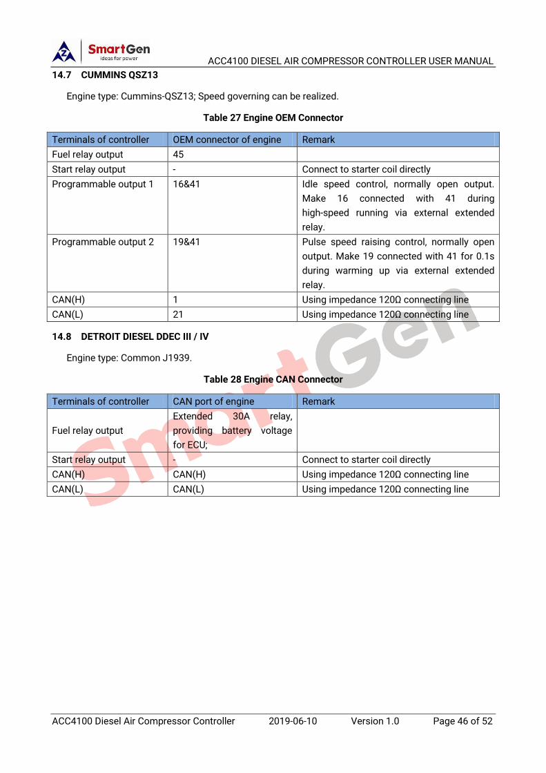
ACC4100 DIESEL AIR COMPRESSOR CONTROLLER USER MANUAL
ACC4100 Diesel Air Compressor Controller 2019-06-10 Version 1.0 Page 46 of 52
14.7 CUMMINS QSZ13
Engine type: Cummins-QSZ13; Speed governing can be realized.
Table 27 Engine OEM Connector
Terminals of controller OEM connector of engine Remark
Fuel relay output 45
Start relay output - Connect to starter coil directly
Programmable output 1 16&41 Idle speed control, normally open output.
Make 16 connected with 41 during
high-speed running via external extended
relay.
Programmable output 2 19&41 Pulse speed raising control, normally open
output. Make 19 connected with 41 for 0.1s
during warming up via external extended
relay.
CAN(H) 1 Using impedance 120Ω connecting line
CAN(L) 21 Using impedance 120Ω connecting line
14.8 DETROIT DIESEL DDEC III / IV
Engine type: Common J1939.
Table 28 Engine CAN Connector
Terminals of controller CAN port of engine Remark
Fuel relay output
Extended 30A relay,
providing battery voltage
for ECU;
Start relay output - Connect to starter coil directly
CAN(H) CAN(H) Using impedance 120Ω connecting line
CAN(L) CAN(L) Using impedance 120Ω connecting line
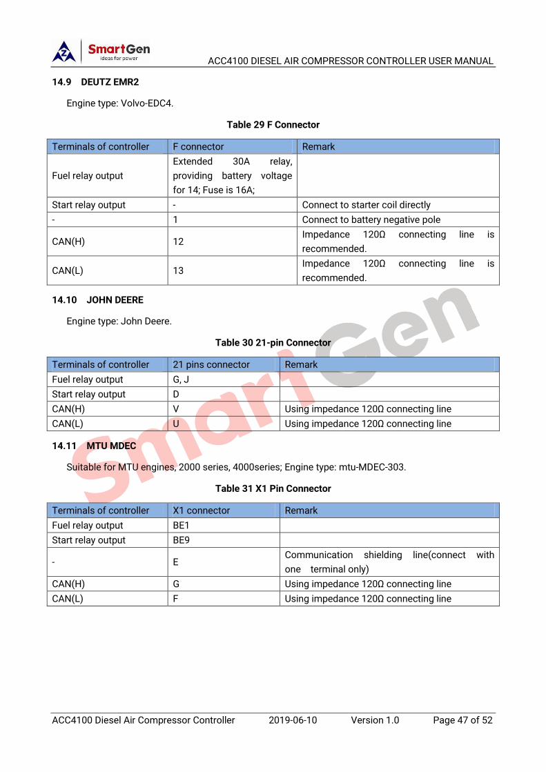
ACC4100 DIESEL AIR COMPRESSOR CONTROLLER USER MANUAL
ACC4100 Diesel Air Compressor Controller 2019-06-10 Version 1.0 Page 47 of 52
14.9 DEUTZ EMR2
Engine type: Volvo-EDC4.
Table 29 F Connector
Terminals of controller F connector Remark
Fuel relay output
Extended 30A relay,
providing battery voltage
for 14; Fuse is 16A;
Start relay output - Connect to starter coil directly
- 1 Connect to battery negative pole
CAN(H) 12 Impedance 120Ω connecting line is
recommended.
CAN(L) 13 Impedance 120Ω connecting line is
recommended.
14.10 JOHN DEERE
Engine type: John Deere.
Table 30 21-pin Connector
Terminals of controller 21 pins connector Remark
Fuel relay output G, J
Start relay output D
CAN(H) V Using impedance 120Ω connecting line
CAN(L) U Using impedance 120Ω connecting line
14.11 MTU MDEC
Suitable for MTU engines, 2000 series, 4000series; Engine type: mtu-MDEC-303.
Table 31 X1 Pin Connector
Terminals of controller X1 connector Remark
Fuel relay output BE1
Start relay output BE9
- E Communication shielding line(connect with
one terminal only)
CAN(H) G Using impedance 120Ω connecting line
CAN(L) F Using impedance 120Ω connecting line

ACC4100 DIESEL AIR COMPRESSOR CONTROLLER USER MANUAL
ACC4100 Diesel Air Compressor Controller 2019-06-10 Version 1.0 Page 48 of 52
14.12 MTU ADEC(SMART MODULE)
Suitable for MTU engine with ADEC (ECU8) and SMART module; Engine type: mtu-ADEC.
Table 32 ADEC (X1 Port)
Terminals of controller ADEC (X1port) Remark
Fuel relay output X1 10 X1 Terminal 9 connected to negative of battery
Start relay output X1 34 X1 Terminal 33 connected to negative of battery
Table 33 ADEC (X4 Port)
Terminals of controller SMART (X4 port) Remark
CAN(H) X4 1 Using impedance 120Ω connecting line
CAN(L) X4 2 Using impedance 120Ω connecting line
14.13 MTU ADEC (SAM MODULE)
Suitable for MTU engine with ADEC (ECU7) and SAM module; Engine type: Common J1939.
Table 34 ADEC (X1 Port)
Terminals of controller ADEC (X1port) Remark
Fuel relay output X1 43 X1 Terminal 28 connected to negative of battery
Start relay output X1 37 X1 Terminal 22 connected to negative of battery
Table 35 SAM (X23 Port)
Terminals of controller SAM (X23 port) Remark
CAN(H) X23 2 Using impedance 120Ω connecting line
CAN(L) X23 1 Using impedance 120Ω connecting line
14.14 PERKINS
Suitable for ADEM3/ ADEM4 engine control module; Engine model is 2306, 2506, 1106, and 2806;
Engine type: Perkins.
Table 36 Connector
Terminals of controller Connector Remark
Fuel relay output 1,10,15,33,34
Start relay output - Connect to starter coil directly
CAN(H) 31 Using impedance 120Ω connecting line
CAN(L) 32 Using impedance 120Ω connecting line

ACC4100 DIESEL AIR COMPRESSOR CONTROLLER USER MANUAL
ACC4100 Diesel Air Compressor Controller 2019-06-10 Version 1.0 Page 49 of 52
14.15 SCANIA
Suitable for S6 engine control module; Engine model is DC9, DC12, and DC16. Engine type: Scania.
Table 37 B1 Connector
Terminals of controller B1 connector Remark
Fuel relay output 3
Start relay output - Connect to starter coil directly
CAN(H) 9 Using impedance 120Ω connecting line
CAN(L) 10 Using impedance 120Ω connecting line
14.16 VOLVO EDC3
Suitable engine control mode is TAD1240, TAD1241, and TAD1242; Engine type: Volvo.
Table 38 "Stand alone" Connector
Terminals of controller “Stand alone” connector Remark
Fuel relay output H
Start relay output E
Programmable output 1 P ECU power
Set configurable output 1 "ECU power";
Table 39 "Data Bus" Connector
Terminals of controller “Data bus” connector Remark
CAN(H) 1 Using impedance 120Ω connecting line
CAN(L) 2 Using impedance 120Ω connecting line
NOTE: When this engine type is selected, preheating time should be set to at least 3 seconds.
14.17 VOLVO EDC4
Suitable engine models are TD520, TAD520 (optional), TD720, TAD720 (optional), TAD721, TAD722,
and TAD732. Engine type: Volvo-EDC4.
Table 40 Connector
Terminals of controller Connector Remark
Fuel relay output
Extended 30A relay,
providing battery voltage
for terminal 14; Fuse is 16A
Start relay output - Connect to starter coil directly
1 Connected to negative of battery
CAN(H) 12 Using impedance 120Ω connecting line
CAN(L) 13 Using impedance 120Ω connecting line

ACC4100 DIESEL AIR COMPRESSOR CONTROLLER USER MANUAL
ACC4100 Diesel Air Compressor Controller 2019-06-10 Version 1.0 Page 50 of 52
14.18 VOLVO-EMS2
Volvo Engine models are TAD734, TAD940, TAD941, TAD1640, TAD1641, and TAD1642. Engine type:
Volvo-EMS2. Speed regulating can be realized.
Table 41 Engine CAN Port
Terminals of controller Engine’s CAN port Remark
programmable output 1 6 ECU stop
Set configurable output 1 to “ECU stop”;
Programmable output 2 5 ECU power
Set configurable output 2 to “ECU power”;
3 Negative power
4 Positive power
CAN(H) 1(Hi) Using impedance 120Ω connecting line
CAN(L) 2(Lo) Using impedance 120Ω connecting line
NOTE: When this engine type is selected, preheating time should be set to at least 3 seconds.
14.19 YUCHAI
Suitable for BOSCH common rail pump engine; Engine type: BOSCH; and speed regulating can be
realized.
Table 42 Engine 42-pin Port
Terminals of controller Engine 42 pins port Remark
Fuel relay output 1.40 Connect to engine ignition lock
Start relay output - Connect to starter coil directly
CAN(H) 1.35 Using impedance 120Ω connecting line
CAN(L) 1.34 Using impedance 120Ω connecting line
Table 43 Engine 2-pin Port
Battery Engine 2 pins Remark
Battery negative 1 Wire diameter 2.5mm2
Battery positive 2 Wire diameter 2.5mm2
14.20 WEICHAI
Suitable for Weichai BOSCH common rail pump engine; Engine type: GTSC1; and speed regulating
can be realized.
Table 44 Engine Port
Terminals of controller Engine port Remark
Fuel relay output 1.40 Connect to engine ignition switch
Start relay output 1.61
CAN(H) 1.35 Using impedance 120Ω connecting line
CAN(L) 1.34 Using impedance 120Ω connecting line
NOTE: If there is any question of connection between controller and ECU communication, please
feel free to contact SmartGen’s service.

ACC4100 DIESEL AIR COMPRESSOR CONTROLLER USER MANUAL
ACC4100 Diesel Air Compressor Controller 2019-06-10 Version 1.0 Page 51 of 52
15 TROUBLE SHOOTING
Table 45 Troubleshooting
Symptoms Possible Solutions
Controller no response with
power
Check starter battery;
Check controller wirings;
Check DC fuse.
Engine stop Check water/cylinder temperature is too high;
Check DC fuse.
Controller emergency stop Check emergency stop button function is right or not;
Check wire connection is open circuit or not.
Oil pressure low alarm after
crank disconnection Check oil pressure and its wire connections.
Water temperature high
alarm after crank
disconnection
Check water temperature sensor and its wire connections.
Shutdown alarm in running Check related switch and wirings according to LCD information;
Check programmable input ports.
Crank disconnect failure
Check fuel circuit and related wirings;
Check starter battery;
Check speed sensor and its wire connections;
Refer to engine manual.
None response for starter Check starter wire connections;
Check starter battery.
RS485 communication is
abnormal
Check RS485 wire connections;
Check RS485 port settings are correct or not;
Check RS485 A and B are connected reversely or not;
Check RS485 transfer module is damaged or not;
Check PC communication port is damaged or not.
ECU communication failure
Check wire CAN high and CAN low polarity;
Check 120Ω resistor is connected correctly or not;
Check engine type is selected right or not;
Check wire connection between controller and engine is right or not;
output port settings are right or not.
ECU warning or shutdown
Refer to alarm screen to obtain information;
If there is detailed alarm information, then check engine according to it;
If there is not, refer to engine manual to obtain information according to
SPN alarm code.

ACC4100 DIESEL AIR COMPRESSOR CONTROLLER USER MANUAL
ACC4100 Diesel Air Compressor Controller 2019-06-10 Version 1.0 Page 52 of 52
16 PACKING LIST
Table 46 Packing List
No. Name Number Remark
1 Controller 1
2 Fixing Clips 2
3 Certificate 1
4 User Manual 1
_________________________________