Embed Size (px)
Citation preview
AT-IMC100T/SCSM
AT-IMC100T/SCMM
Fast Ethernet Industrial Media Converter
User Manual613-001984 Rev A

Copyright © 2001-2014 Allied Telesis Holdings K. K. - all rights reserved.
No part of this publication may be reproduced without prior written permission from Allied Telesis, Inc.
Allied Telesis and the Allied Telesis logo are trademarks of Allied Telesis, Incorporated. All other product names, company names, logos or other designations mentioned herein are trademarks or registered trademarks of their respective owners.
Allied Telesis, Inc. reserves the right to make changes in specifications and other information contained in this document without prior written notice. The information provided herein is subject to change without notice. In no event shall Allied Telesis, Inc. be liable for any incidental, special, indirect, or consequential damages whatsoever, including but not limited to lost profits, arising out of or related to this manual or the information contained herein, even if Allied Telesis, Inc. has been advised of, known, or should have known, the possibility of such damages.
AT-IMC100T/SCSM and AT-IMC100T/SCMM Fast Ethernet Industrial Media Converters
Preface
I FCC Warning
This Equipment has been tested and found to comply with the limits for a Class-A digital device, pursuant to Part 15 of the FCC rules. These limits are designed to provide reasonable protection against harmful interference in a residential installa-tion. This equipment generates, uses, and can radiate radio frequency energy. It may cause harmful interference to radio com-munications if the equipment is not installed and used in accordance with the instructions. However, there is no guarantee that interference will not occur in a particular installation. If this equipment does cause harmful interference to radio or tele-vision reception, which can be determined by turning the equipment off and on, the user is encouraged to try to correct the interference by one or more of the following measures:
• Reorient or relocate the receiving antenna.
• Increase the separation between the equipment and receiver.
• Connect the equipment into an outlet on a circuit different from that to which the receiver is connected.
• Consult the dealer or an experienced radio/TV technician for help.
II CE Mark Warning
This is a Class-A product. In a domestic environment this product may cause radio interference in which case the user may be required to take adequate measures.
Table of Contents
Introduction..........................................................................................................................5Features ................................................................................................................................5Packing List .........................................................................................................................7Safety Precaution .................................................................................................................7
Front Panel ...........................................................................................................................8Top View .............................................................................................................................8Wiring the Power Inputs ......................................................................................................9Wiring the Fault Alarm Contact ........................................................................................10LED Indicators...................................................................................................................10DIP-Switch.........................................................................................................................11Ports ...................................................................................................................................12
DIN-Rail Mounting............................................................................................................14Wall-Mount Plate Fixing ...................................................................................................16
Installing Copper Ethernet Cable.......................................................................................17Installing SFP Module and Fiber Cable.............................................................................17
Selecting a Location...........................................................................................................19Installation Steps................................................................................................................19
Overview Introduction
5AT-IMC100T/SCSM and AT-IMC100T/SCMM Fast Ethernet Industrial Media Converters
1. Overview
1.1 Introduction
The Fast Ethernet Industrial Media Converter is a cost-effective solution for the converting between 10/100Base-TX and 100Base-FX cabling, it allows you to extend the cabling distance of your 100Base-FX network up to 2 kilometers for multi-mode fiber or 40 kilometers for single-mode fiber. The Fiber Converter module gives you the option to choose from the most popular fiber cabling connectors: SC multi-mode and single-mode connector..
1.1.1 Dual Power Inputs
To reduce the risk of power failure, the Fast Ethernet Industrial Media Converter provides +12 ~ 48 VDC dual power inputs. When the primary power input fails, the device will automatically switch to the secondary power input
1.1.2 Flexible Mounting
Fast Ethernet Industrial Media Converter is extremely compact and can be mounted on a DIN-rail or a wall, so it is suitable for any space-constrained environment.
1.1.3 Wide Operating Temperature
The operating temperature of the Fast Ethernet Industrial Media Converter is between -40 ~ 75°C. With such a wide range, you can use the Industrial Media Converter in some of the harshest industrial environments exist.
1.1.4 Easy Troubleshooting
LED indicators make troubleshooting quick and easy. The LED indicators help you immediately diagnose the system power, link status, transmission speed and collision status.
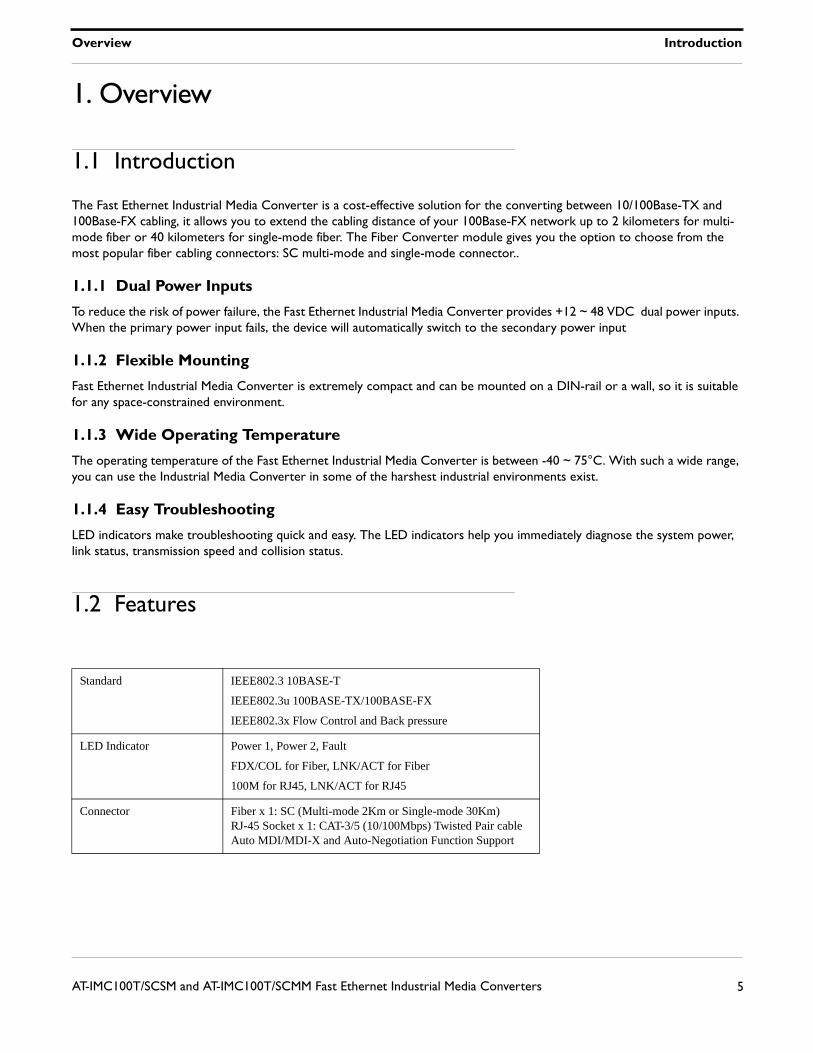
1.2 Features
Standard IEEE802.3 10BASE-T
IEEE802.3u 100BASE-TX/100BASE-FX
IEEE802.3x Flow Control and Back pressure
LED Indicator Power 1, Power 2, Fault
FDX/COL for Fiber, LNK/ACT for Fiber
100M for RJ45, LNK/ACT for RJ45
Connector Fiber x 1: SC (Multi-mode 2Km or Single-mode 30Km)RJ-45 Socket x 1: CAT-3/5 (10/100Mbps) Twisted Pair cable Auto MDI/MDI-X and Auto-Negotiation Function Support
Overview Features
6AT-IMC100T/SCSM and AT-IMC100T/SCMM Fast Ethernet Industrial Media Converters
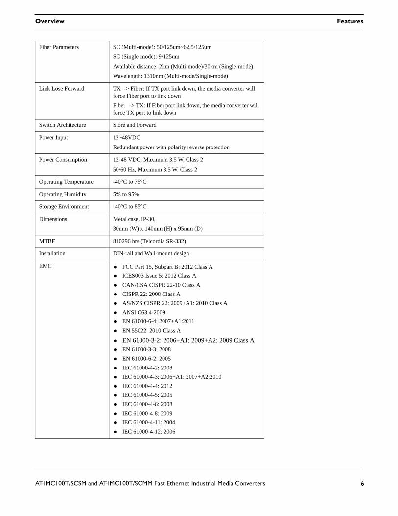
Fiber Parameters SC (Multi-mode): 50/125um~62.5/125um
SC (Single-mode): 9/125um
Available distance: 2km (Multi-mode)/30km (Single-mode)
Wavelength: 1310nm (Multi-mode/Single-mode)
Link Lose Forward TX -> Fiber: If TX port link down, the media converter will force Fiber port to link down
Fiber -> TX: If Fiber port link down, the media converter will force TX port to link down
Switch Architecture Store and Forward
Power Input 12~48VDC
Redundant power with polarity reverse protection
Power Consumption 12-48 VDC, Maximum 3.5 W, Class 2
50/60 Hz, Maximum 3.5 W, Class 2
Operating Temperature -40°C to 75°C
Operating Humidity 5% to 95%
Storage Environment -40°C to 85°C
Dimensions Metal case. IP-30,
30mm (W) x 140mm (H) x 95mm (D)
MTBF 810296 hrs (Telcordia SR-332)
Installation DIN-rail and Wall-mount design
EMC • FCC Part 15, Subpart B: 2012 Class A
• ICES003 Issue 5: 2012 Class A
• CAN/CSA CISPR 22-10 Class A
• CISPR 22: 2008 Class A
• AS/NZS CISPR 22: 2009+A1: 2010 Class A
• ANSI C63.4-2009
• EN 61000-6-4: 2007+A1:2011
• EN 55022: 2010 Class A
• EN 61000-3-2: 2006+A1: 2009+A2: 2009 Class A
• EN 61000-3-3: 2008
• EN 61000-6-2: 2005
• IEC 61000-4-2: 2008
• IEC 61000-4-3: 2006+A1: 2007+A2:2010
• IEC 61000-4-4: 2012
• IEC 61000-4-5: 2005
• IEC 61000-4-6: 2008
• IEC 61000-4-8: 2009
• IEC 61000-4-11: 2004
• IEC 61000-4-12: 2006
Overview Packing List
7AT-IMC100T/SCSM and AT-IMC100T/SCMM Fast Ethernet Industrial Media Converters
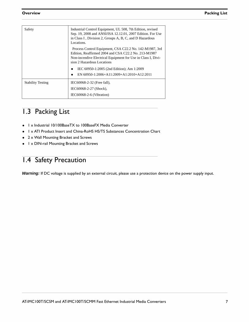
1.3 Packing List
• 1 x Industrial 10/100BaseTX to 100BaseFX Media Converter
• 1 x ATI Product Insert and China-RoHS HS/TS Substances Concentration Chart
• 2 x Wall Mounting Bracket and Screws
• 1 x DIN-rail Mounting Bracket and Screws
1.4 Safety Precaution
Warning: If DC voltage is supplied by an external circuit, please use a protection device on the power supply input.
Safety Industrial Control Equipment, UL 508, 7th Edition, revised Sep. 19, 2008 and ANSI/ISA 12.12.01, 2007 Edition. For Use in Class I , Division 2, Groups A, B, C, and D Hazardous Locations.
Process Control Equipment, CSA C22.2 No. 142-M1987, 3rd Edition, Reaffirmed 2004 and CSA C22.2 No. 213-M1987 Non-incendive Electrical Equipment for Use in Class I, Divi-sion 2 Hazardous Locations
• IEC 60950-1:2005 (2nd Edition); Am 1:2009
• EN 60950-1:2006+A11:2009+A1:2010+A12:2011
Stability Testing IEC60068-2-32 (Free fall),
IEC60068-2-27 (Shock),
IEC60068-2-6 (Vibration)
Hardware Description Front Panel
8AT-IMC100T/SCSM and AT-IMC100T/SCMM Fast Ethernet Industrial Media Converters
2. Hardware Description
The Fast Ethernet Industrial Media Converter dimensions: 30mm (W) x 140mm (H) x 95mm (D)
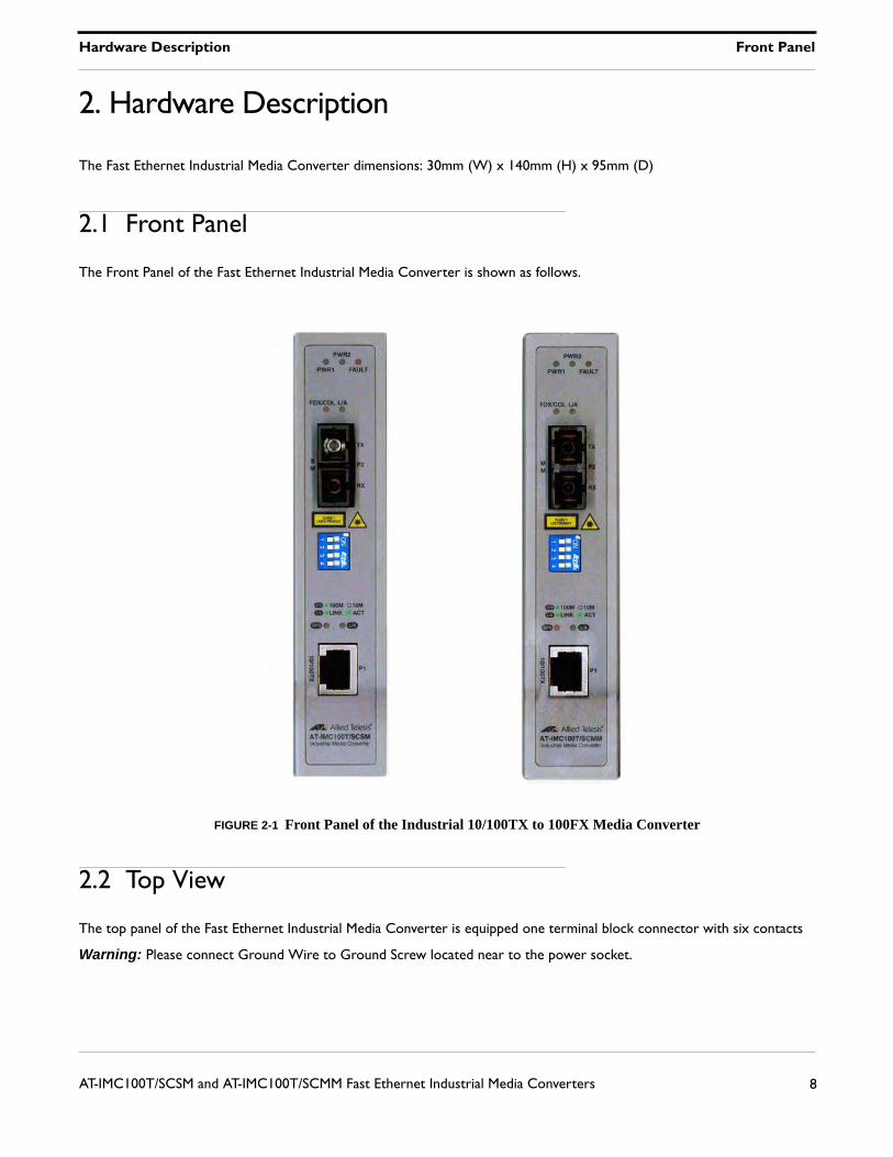
2.1 Front Panel
The Front Panel of the Fast Ethernet Industrial Media Converter is shown as follows.
FIGURE 2-1 Front Panel of the Industrial 10/100TX to 100FX Media Converter
2.2 Top View
The top panel of the Fast Ethernet Industrial Media Converter is equipped one terminal block connector with six contacts
Warning: Please connect Ground Wire to Ground Screw located near to the power socket.
Hardware Description Wiring the Power Inputs
9AT-IMC100T/SCSM and AT-IMC100T/SCMM Fast Ethernet Industrial Media Converters
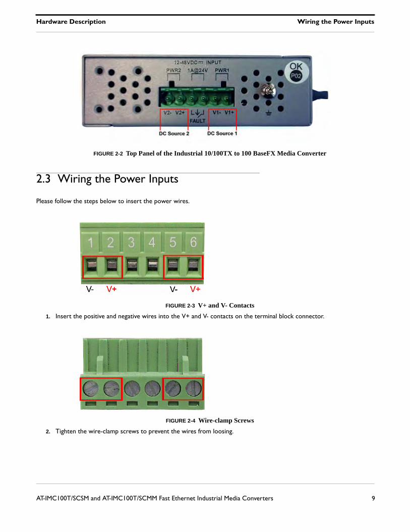
FIGURE 2-2 Top Panel of the Industrial 10/100TX to 100 BaseFX Media Converter
2.3 Wiring the Power Inputs
Please follow the steps below to insert the power wires.
FIGURE 2-3 V+ and V- Contacts
1. Insert the positive and negative wires into the V+ and V- contacts on the terminal block connector.
FIGURE 2-4 Wire-clamp Screws
2. Tighten the wire-clamp screws to prevent the wires from loosing.
Hardware Description Wiring the Fault Alarm Contact
10AT-IMC100T/SCSM and AT-IMC100T/SCMM Fast Ethernet Industrial Media Converters
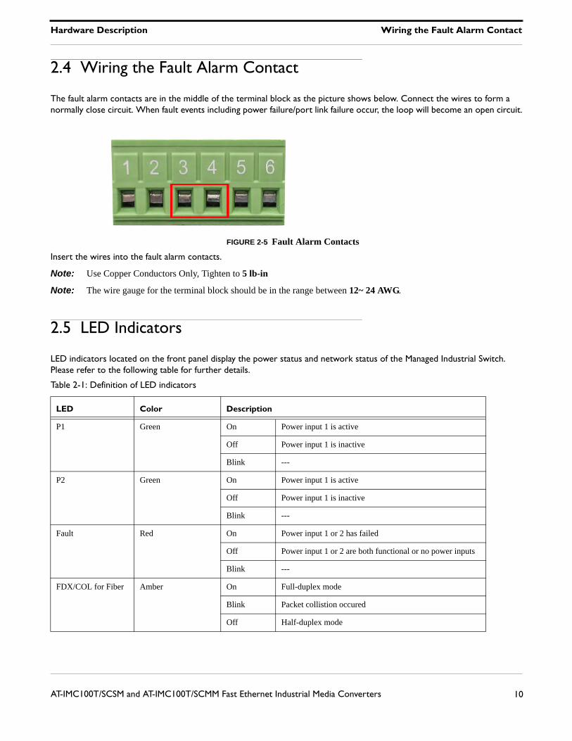
2.4 Wiring the Fault Alarm Contact
The fault alarm contacts are in the middle of the terminal block as the picture shows below. Connect the wires to form a normally close circuit. When fault events including power failure/port link failure occur, the loop will become an open circuit.
FIGURE 2-5 Fault Alarm Contacts
Insert the wires into the fault alarm contacts.
Note: Use Copper Conductors Only, Tighten to 5 lb-in
Note: The wire gauge for the terminal block should be in the range between 12~ 24 AWG.
2.5 LED Indicators
LED indicators located on the front panel display the power status and network status of the Managed Industrial Switch. Please refer to the following table for further details.
Table 2-1: Definition of LED indicators
LED Color Description
P1 Green On Power input 1 is active
Off Power input 1 is inactive
Blink ---
P2 Green On Power input 1 is active
Off Power input 1 is inactive
Blink ---
Fault Red On Power input 1 or 2 has failed
Off Power input 1 or 2 are both functional or no power inputs
Blink ---
FDX/COL for Fiber Amber On Full-duplex mode
Blink Packet collistion occured
Off Half-duplex mode
Hardware Description DIP-Switch
11AT-IMC100T/SCSM and AT-IMC100T/SCMM Fast Ethernet Industrial Media Converters
2.6 DIP-Switch
Table 2-2: DIP-Switch Status Description
Link Lose Forwarding (DIP-Switch 2): When LLF enabled, it allows UTP link failures to be reported to the fiber side and also allows Fiber link failures to be reported to the UTP side. Therefore, a link fault pass-through feature is provided in both UTP and Fiber side.
Media mode (DIP-Switch 4): When media mode is enabled (ON), it operates with the minimum latency. The transmis-sion flow does not wait until entire frame is ready, but instead it forwards the received data immediately after the data being received. And TP port should be forced at 100M in this application. When DIP-Switch is in switching mode (OFF), the con-verter function is the same as a Switch Hub.
Note: Please don't change the DIP-switch setting when UTP or fiber port is transmitting or receiving data. It may cause some data error. Besides, if you change the DIP-switch setting, please power off the converter and power on again to make the setting effective.
LNK/ACT for Fiber Green On Connected to network
Blink Networking is active
Off Not connected to network
100M for RJ-45 Amber On Link to 100Mbps network
Blink ---
Off Link to 10Mbps network
LNK/ACT for RJ-45 Green On Connected to network
Blink Networking is active
Off Not connected to network
S/W No Status Description
1 On Enables Port/Power Alarm
Off Disables Port/Power Alarm
2 On Enables LLF
Off Disables LLF
3 On 100Base-FX Half-mode
Off 100Base-FX Full-mode
4 On Media mode (100TX to 100FX)
Off Switching mode
Table 2-1: Definition of LED indicators
LED Color Description
Hardware Description Ports
12AT-IMC100T/SCSM and AT-IMC100T/SCMM Fast Ethernet Industrial Media Converters
2.7 Ports
RJ-45 ports (Auto MDI/MDIX): The RJ-45 ports are auto-sensing for 10Base-T or 100Base-TX devices connections. Auto MDI/MDIX means that you can connect to another switch or workstation without changing straight through or crossover cabling. See figures as below for straight through and crossover cable schematic.
2.7.1 RJ-45 Pin Assignments
Note: "+" and "-" signs represent the polarity of the wires that make up each wire pair.
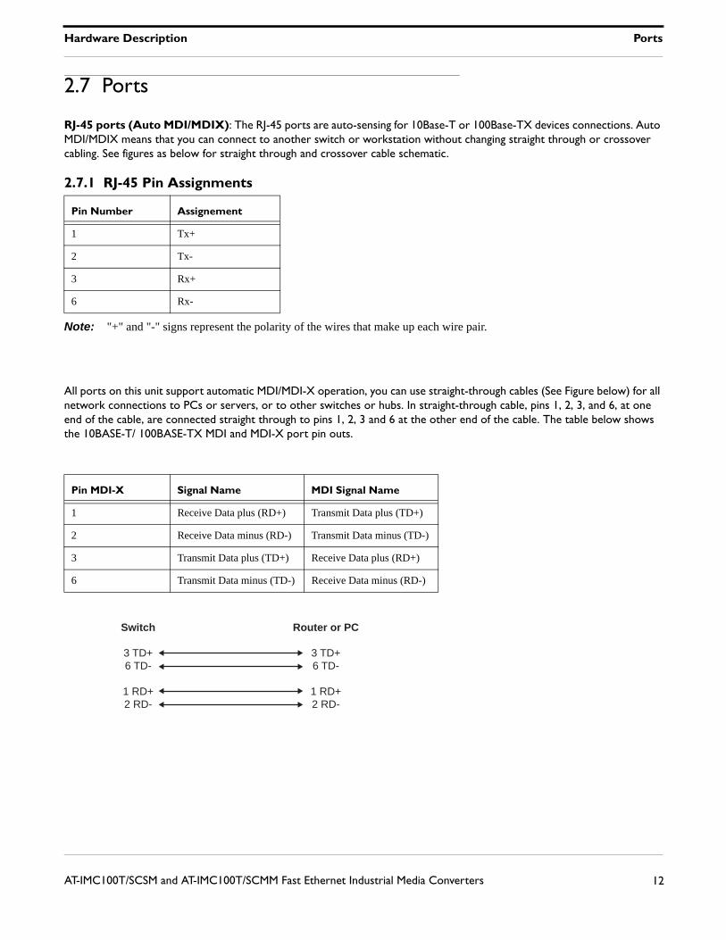
All ports on this unit support automatic MDI/MDI-X operation, you can use straight-through cables (See Figure below) for all network connections to PCs or servers, or to other switches or hubs. In straight-through cable, pins 1, 2, 3, and 6, at one end of the cable, are connected straight through to pins 1, 2, 3 and 6 at the other end of the cable. The table below shows the 10BASE-T/ 100BASE-TX MDI and MDI-X port pin outs.
Pin Number Assignement
1 Tx+
2 Tx-
3 Rx+
6 Rx-
Pin MDI-X Signal Name MDI Signal Name
1 Receive Data plus (RD+) Transmit Data plus (TD+)
2 Receive Data minus (RD-) Transmit Data minus (TD-)
3 Transmit Data plus (TD+) Receive Data plus (RD+)
6 Transmit Data minus (TD-) Receive Data minus (RD-)
Switch Router or PC
3 TD+6 TD-
1 RD+2 RD-
3 TD+6 TD-
1 RD+2 RD-
Hardware Description Ports
13AT-IMC100T/SCSM and AT-IMC100T/SCMM Fast Ethernet Industrial Media Converters
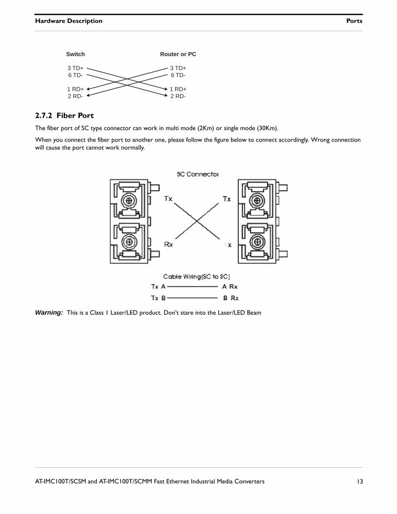
2.7.2 Fiber Port
The fiber port of SC type connector can work in multi mode (2Km) or single mode (30Km).
When you connect the fiber port to another one, please follow the figure below to connect accordingly. Wrong connection will cause the port cannot work normally.
Warning: This is a Class 1 Laser/LED product. Don't stare into the Laser/LED Beam
Switch Router or PC
3 TD+6 TD-
1 RD+2 RD-
3 TD+6 TD-
1 RD+2 RD-
Mounting Installation DIN-Rail Mounting
14AT-IMC100T/SCSM and AT-IMC100T/SCMM Fast Ethernet Industrial Media Converters
3. Mounting Installation
3.1 DIN-Rail Mounting
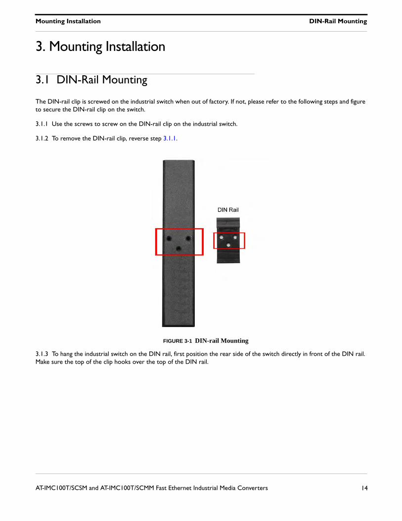
The DIN-rail clip is screwed on the industrial switch when out of factory. If not, please refer to the following steps and figure to secure the DIN-rail clip on the switch.
3.1.1 Use the screws to screw on the DIN-rail clip on the industrial switch.
3.1.2 To remove the DIN-rail clip, reverse step 3.1.1.
FIGURE 3-1 DIN-rail Mounting
3.1.3 To hang the industrial switch on the DIN rail, first position the rear side of the switch directly in front of the DIN rail. Make sure the top of the clip hooks over the top of the DIN rail.
Mounting Installation DIN-Rail Mounting
15AT-IMC100T/SCSM and AT-IMC100T/SCMM Fast Ethernet Industrial Media Converters
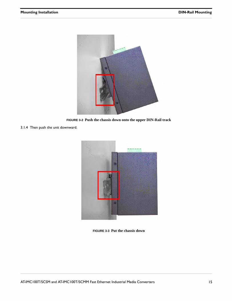
FIGURE 3-2 Push the chassis down onto the upper DIN-Rail track
3.1.4 Then push the unit downward.
FIGURE 3-3 Put the chassis down
Mounting Installation Wall-Mount Plate Fixing
16AT-IMC100T/SCSM and AT-IMC100T/SCMM Fast Ethernet Industrial Media Converters
3.1.5 Check the DIN-Rail clip is tightly fixed on the DIN rail.
3.1.6 To remove the industrial switch from the track, reverse the steps above.
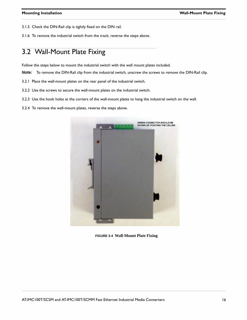
3.2 Wall-Mount Plate Fixing
Follow the steps below to mount the industrial switch with the wall mount plates included.
Note: To remove the DIN-Rail clip from the industrial switch, unscrew the screws to remove the DIN-Rail clip.
3.2.1 Place the wall-mount plates on the rear panel of the industrial switch.
3.2.2 Use the screws to secure the wall-mount plates on the industrial switch.
3.2.3 Use the hook holes at the corners of the wall-mount plates to hang the industrial switch on the wall.
3.2.4 To remove the wall-mount plates, reverse the steps above.
FIGURE 3-4 Wall-Mount Plate Fixing

Cabling Installation Installing Copper Ethernet Cable
17AT-IMC100T/SCSM and AT-IMC100T/SCMM Fast Ethernet Industrial Media Converters
4. Cabling Installation
4.1 Installing Copper Ethernet Cable
4.1.1 Insert one side of Category 5 cables into the Ethernet port (RJ-45 port) and another side of category 5 cables to the network devices' Ethernet port (RJ-45 port), ex: switch, PC, or Server. The UTP port (RJ-45) LED on the unit will light up when the cable is connected and network is active. Please refer to the section LED Indicators for LED light meaning.
4.1.2 Connect fiber cabling as explained in paragraph 2.7.2.
4.1.3 When all connections are all set and LED lights all show in normal, the installation is complete.
4.2 Installing SFP Module and Fiber Cable
4.2.1 The cable between the link partner (switch, hub, workstation, etc.) and the converter must be less than 100 meters (328 ft.) long and comply with the IEEE 802.3ab 1000Base-T standard for Category 5e or above.
4.2.2 Fiber segment using single-mode connector type must use 9/125ìm single-mode fiber cable. You can connect two devices in the distance of 10km or more, accordingly with the SFP module capabilities. Fiber segment using multi-mode connector type must use 50/125 or 62.5/125ìm multi-mode fiber cable. You can connect two devices up to 550m distances.
4.2.3 The small form-factor pluggable (SFP module) is a compact optical transceiver used in optical communications for both telecommunication and data communication applications.
Troubleshooting
18AT-IMC100T/SCSM and AT-IMC100T/SCMM Fast Ethernet Industrial Media Converters
5. Troubleshooting
• Verify that you are using the right power cord/adapter (DC 12-48V), please don't use the power adapter with DC output higher than 48V, or it will burn this converter down.
• Select the proper UTP/STP cable to construct your network. Please check that you are using the right cable. Use unshielded twisted-pair (UTP) or shield twisted-pair (STP) cable for RJ-45 connections: 100Ω Category 3, 4 or 5 cables for 10Mbps connections or 100Ω Category 5 cable for 100Mbps connections. Also be sure that the length of any twisted-pair connection does not exceed 100 meters (328 feet).
• Diagnosing LED Indicators: the unit can be easily monitored through panel indicators to assist in identifying problems, which describes common problems you may encounter and where you can find possible solutions.
• If the power indicator does not light up when the power cord is plugged in, you may have a problem with power cord. Then check for loose power connections, power losses or surges at power outlet. IF you still cannot resolve the problem, contact your local dealer for assistance.
• If the LED indicators are normal and the connected cables are correct and the packets still cannot transmit, please check your system's Ethernet devices' configuration or status.
Hardware Installation Selecting a Location
19AT-IMC100T/SCSM and AT-IMC100T/SCMM Fast Ethernet Industrial Media Converters
6. Hardware Installation
6.1 Selecting a Location
Here are the guidelines for choosing a location for the media converter:
• The Fast Ethernet Industrial Media Converter may be installed on a wall or on DINRAIL.
Note: The DINRAIL bracket must be ordered separately from the AT-PC2002/POE+ media converter
Caution: The Fast Ethernet Industrial Media Converter must be powered only by a UL Listed power supply marked either "LPS" (or Class 2) rated 56Vdc, 1A.
Caution: The Fast Ethernet Industrial Media Converter must NOT be operated from Centralized DC battery.
• The site should provide easy access to the ports on the front of the chassis so that you can easily connect and disconnect the network cables, as well as view the unit’s LEDs.
• Air flow around the unit and through the side vents should not be unrestricted.
• Do not place objects on top of the chassis.
• Do not expose the device to moisture or water.
• Make sure that the site is in a dust-free environment.
• Use dedicated power circuits or power conditioners to supply reliable electrical power to the network devices
• Keep the media converter chassis and the twisted pair cable away from sources of electrical noise, such as radios, electric motors, transmitters, broadband amplifiers, power lines, and fluorescent fixtures.
6.2 Installation Steps
6.2.1 Unpack the unit packing.
6.2.2 Check the DIN-rail clip is screwed on the unit. If the DIN-rail clip is not screwed on the unit, please refer to the DIN-Rail Mounting section for DIN-rail installation. If you want to wall-mount the unit, then please refer to the Wall-Mount Plate Fixing section.
6.2.3 To hang the unit on the DIN-rail track or wall, please refer to the Mounting Installation section.
6.2.4 Connect Ground Wire to the Ground screw located near the Power Socket.
6.2.5 Power on the Unit and the power LED indicator on the unit will light up. Please refer to the Wiring the Power Inputs section on how to wire the power. Please refer to the LED Indicators section for meaning of LED lights.
6.2.6 Prepare the twisted-pair, straight through Category 5 cable for Ethernet connection.
6.2.7 Insert one side of Category 5 cables into the Ethernet port (RJ-45 port). The UTP port (RJ-45) LED on the unit will light up when the cable is connected and network is active. Please refer to the LED Indicators section for LED light meaning.
6.2.8 Insert the fiber cable SC connector into the fiber port.
6.2.9 When all connections are all set and LED lights all show in normal, the installation is complete.
Reviewing the Safety Guidelines
20AT-IMC100T/SCSM and AT-IMC100T/SCMM Fast Ethernet Industrial Media Converters
7. Reviewing the Safety Guidelines
Please review the following safety guidelines before you begin to install the AT-IMC1000TP/SFP Industrial Media Converter.
Note: The indicates that a translation of the safety statement is available in a PDF document titled “Translated Safety Statements” posted on the Allied Telesis website at www.alliedtelesis.com.
Note: Refer to the documentation that comes with the SFP module to determine whether the module is a Class 1 LED product or a Class 1 Laser product.
Warning: Class 1 Laser product. L1
Warning: Do not stare into the laser beam. L2
Warning: Class 1 LED product. L3
Warning: The fiber optic ports contain a Class 1 laser device. When the ports are disconnected, always cover them with the provided plug. Exposed ports may cause skin or eye damage L4
Warning: Do not look directly at the fiber optic cable ends or inspect the cable ends with an optical lens. L6
Warning: To prevent electric shock, do not remove the cover. No user-serviceable parts inside. This unit contains hazardous voltages and should only be opened by a trained and qualified technician. To avoid the possibility of electric shock, disconnect electric power to the product before connecting or disconnecting the LAN cables. E1
Caution: Air vents must not be blocked and must have free access to the room ambient air for cooling. E6
Warning: Operating Temperature. This product is designed for a maximum ambient temperature of 75° degrees C. E53All Countries: Install product in accordance with local and National Electrical Codes. E8
Warning: Do not strip more than the recommended amount of wire. Stripping more than the recommended amount can create a safety hazard by leaving exposed wire on the terminal block after installation. E10
Warning: Check to see if there are any exposed copper strands coming from the installed wire. When this installation is done correctly there should be no exposed copper wire strands extending from the terminal block. Any exposed wiring can conduct harmful levels of electricity to persons touching the wires. E12
Warning: Only trained and qualified personnel are allowed to install or to replace this equipment. E14
Caution: Do not install in direct sunlight, or a damp or dusty place. E16
Note: Circuit Overloading: Consideration should be given to the connection of the equipment to the supply circuit and the effect that overloading of circuits might have on overcurrent protection and supply wiring. Appropriate consideration of equipment nameplate ratings should be used when addressing this concern. E21
Caution: The unit does not contain serviceable components. Please return damaged units for servicing. E42
Caution: During normal operations, the SFP module may have a case temperature that exceeds 70° C (158° F). If you remove the module, exercise caution when handling with unprotected hands. E43