Embed Size (px)
Citation preview

version 2.45USER MANUAL

Thank you for choosing Analog Way. By following these simple steps, you should be able to unleash the powerfull Quattro Value High Resolution Digital and Analog Computer & Video Up/Down Scaler Switcher straight out of the box.
1-1. Accessories supplied1-2. Quattro Value general information1-3. Devices & references1-4. Installation1-5. Front panel description of the Quattro Value1-6. Rear panel description of the QuattroValue
2-1. Quattro Value connections2-2. Input #1 description2-3. Input #2 to 8 description2-4. Output description2-5. Audio inputs2-6. Prelist audio2-7. Audio output
3-1. Settings3-2. Switching operations3-3. Display device adjustments3-4. Image adjustments3-5. Audio adjustments
THANK YOU
TABLE OF CONTENTS
INTRODUCTION
SAFETY INSTRUCTIONS
STARTING
OPERATING MODE
PAGE 1
1
3
8
12
17
4-1. Logo insertion4-2. Using the frame
USING FRAME & LOGO INSERTION 21

FRONT PANEL MENU DISPLAY DESCRIPTION
UPDATING THE DEVICE
REMOTE CONTROL SOFTWARE
TECHNICAL SPECIFICATIONS
APPENDIX : PROGRAMMER’S GUIDE
WARRANTY & SERVICES INFORMATION
5-1. Introduction5-2. Control buttons5-3. Status mode5-4. Control mode5-5. Functions description
6-1. Connections6-2. Update instructions
7-1. Connections7-2. Software installation7-3. Communication setup7-4. Using the software7-5. Frames & Logos Loader
8-1. Computer & video inputs8-2. Display outputs8-3. Audio inputs8-4. Main audio output8-5. Prelist audio output8-6. Communication ports8-7. Trigger8-8. Environmental
A. IntroductionB. Commands structureC. Error responsesD. Commands and responses tableE. ASCII / HEX / DEC TABLEF. RS-232 Sample
PAGE 2
23
37
38
41
44
55
CONTACT INFORMATION 56

SAFETY INSTRUCTIONS
All of the safety and operating instructions should be read before the product is operated and should be retained for further reference. Please follow all of the warnings on this product and its operating instructions.
CAUTION :
• WARNING : Toprevent theriskofelectricshockandfire,donotexposethisdevice torain,humidityorintense heat sources (such as heaters or direct sunlight). Slots and openings in the device are provided for ventilation and to avoid overheating. Make sure the device is never placed on or near a textile surface that could block the openings. Also keep away from excessive dust, vibrations and shocks.
• POWER CORD. : Use the On (I) / Off (O) switch to power On or Off devices equipped with that switch. All other devices should be plugged and unplugged from wall outlet. In both cases, please follow these instructions :
1. The power cord of the device should be unplugged from the outlet when left unused for several days.
2. To unplug the device, do not pull on the power cord but always on the plug itself.3. The outlet should always be near the device and easily accessible.4. Power supply cords should be routed so that they are not likely to be walked on or
pinched by items placed upon or against them.
If the power supply cord is damaged, unplug the device. Using the device with a damaged power supply cord may expose you to electric shocks or other hazards. Verify the condition of the power supply cords once in a while. Contact your dealer or service center for replacement if damaged.
• CONNECTIONS : Allinputsandoutputs(exceptforthepowerinput)areTBTSdefinedunderEN60950.
• SERVICING : Do not attempt to service this product yourself by opening or removing covers and screws sinceitmayexposeyoutoelectricshocksorotherhazards.Referallproblemstoqualifiedservice personnel.
• OPENINGS : Neverpushobjectsofanykind intothisproduct throughtheopenings. If liquidshavebeenspilled or objects have fallen into the device, unplug it immediately and have it checked by a qualifiedtechnician.
PAGE 3

INSTRUCTIONS DE SECURITE
Afindemieuxcomprendrelefonctionnementdecetappareilnousvousconseillonsdebienliretouteslesconsignesdesécurité et de fonctionnement de l’appareil avant utilisation. Conserver les instructions de sécurité et de fonctionnement afindepouvoirlesconsulterultérieurement.Respectertouteslesconsignesmarquéesdansladocumentation,surleproduit et sur ce document.
• ATTENTION : Afindeprévenirtoutrisquedechocélectriqueetd’incendie,nepasexposercetappareilàlapluie,àl’humiditéetauxsourcesdechaleurintense.
• INSTALLATION : Veillez à assurer une circulation d’air suffisante pour éviter toute surchauffe à l’intérieurde l’appareil.Neplacezpas l’appareil sur ouàproximitéd’unesurface textile susceptibled’obstruerlesorificesdeventilation.N’installezpasl’appareilàproximitédesourcesdechaleurcomme un radiateur ou une poche d’air chaud, ni dans un endroit exposé au rayonnement solairedirect,àdespoussièresexcessives,àdesvibrationsouàdeschocsmécaniques.Cecipourrait provoquer un mauvais fonctionnement et un accident.
• ALIMENTATION : Ne faire fonctionner l’appareil qu’avec la sourced’alimentation indiquée sur l’appareil. Lesappareilsdoiventêtreobligatoirementconnectéssurunesourceéquipéed’unemiseàlaterreefficace.Enaucuncascetteliaisondeterrenedevraêtremodifiée,contournéeousupprimée.
• CORDON D’ALIM. : Les appareils sont équipés d’un interrupteur général (Marche I / Arrêt O), la mise en tension et la mise hors tension se fait en actionnant cet interrupteur général. Attention : Le cordon d’alimentation constitue le seul moyen de débrancher l’appareil totalement de l’alimentation secteur. Pour être certain que l’appareil n’est plus alimenté, ce cordon doit être débranché de la prise murale.
Appliquer les consignes suivantes : 1. Le matériel relié a demeure au réseau, doit avoir un dispositif de sectionnement
facilementaccessiblequidoitêtreincoporéàl’extérieurdel’appareil. 2. Débrancher le cordon d’alimentation de la prise murale si vous prévoyez de ne pas
utiliser l’appareil pendant quelques jours ou plus. 3. Pourdébrancherlecordon,tirezleparlafiche.Netirezjamaissurlecordonproprementdit. 3. La prise d’alimentation doit se trouver à proximité de l’appareil et être aisément
accessible. 4. Nelaissezpastomberlecordond’alimentationetneposezpasd’objetslourdsdessus.
Si le cordon d’alimentation est endommagé, débranchez le immédiatement de la prise murale. Il est dangereux de faire fonctionner un appareil avec un cordon endommagé, un câble abîmé peutprovoquerunrisqued’incendieouunchocélectrique.Vérifierlecâbled’alimentationdetempsentemps.Contactervotrerevendeurouleserviceaprèsventepourunremplacement.
• CONNEXIONS : Toutes les entrées et sorties (exceptée l’entrée secteur) sont de type TBTS (Très BasseTensiondeSécurité)définiesselonEN60950.
• RÉPARATION ET MAINTENANCE : L’utilisateur ne doit en aucun cas essayer de procéder aux opérations de dépannage, car l’ouverture des appareils par retrait des capots ou de toutesautrespiècesconstituant lesboîtiersainsi que ledévissagedesvis apparentes à l’extérieur, risque d’exposer l’utilisateur à des chocsélectriquesouautresdangers.Contacterleserviceaprèsventeouvotrerevendeurous’adresseràunpersonnelqualifiéuniquement.
• OUVERTURES ET ORIFICES : Les appareils peuvent comporter des ouvertures (aération, fentes, etc...), veuillez ne jamais y introduire d’objets et ne jamais obstruer ses ouvertures. Si un liquideouunobjet pénètreà l’intérieur de l’appareil, débranchezimmédiatement l’appareil et faites lecontrôlerparunpersonnelqualifiéavant de le remettre en service.
PAGE 4

Allo scopo di capire meglio il funzionamento di questa apparecchiatura vi consigliamo di leggere bene tutti i consigli disicurezzaedifunzionamentoprimadell’utilizzo.Conservareleistruzionidisicurezzaedifunzionamentoalfinedipoterle consultare ulteriormente. Seguire tutti i consigli indicati su questo manuale e sull’apparecchiatura.
• ATTENZIONE : Alfinediprevenirequalsiasirischiodishockelettricoed’incendio,nonesporrel’apparecchiaturaapioggia,umiditàeasorgentidieccessivocalore.
• INSTALLAZIONE : Assicuratevichevisiaunasufficientecircolazioned’ariaperevitarequalsiasisurriscaldamentoall’internodell’apparecchiatura.Noncollocare l’apparecchiatura inprossimitàosusuperficitessilisuscettibilidiostruireilfunzionamentodellaventilazione.Noninstallatel’apparecchiaturainprossimitàdisorgentidicalorecomeunradiatoreounafuoruscitad’ariacalda,néinunposto esposto direttamente ai raggi del sole, a polvere eccessiva, a vibrazioni o a shock meccanici. Ció potrebbe provocare un erroneo funzionamento e un incidente.
• ALIMENTAZIONE : Far funzionare l’apparecchiatura solo con la sorgente d’alimentazione indicata sull’apparecchiatura. Le apparecchiature queste devono essere obbligatoriamente collegate suunasorgentefornitadiunaefficientemessaaterra.Innessuncasoquestocollegamentopotràesseremodificato,sostituitooeliminato.
• CAVO DI ALIMENTAZIONE : Gliapparecchiconuninterrutore(commutatore)generale(AccessoI/Speuto0),accendere ou spagnere l’apparecchio si fa usando l’interrutore.
Attenzione : il cavo di alimentazione è il solo modo di disconnettere l’apparecchio dell’alimentazione. Per assicurarsi che totalemente l’apparecchio non è più collegato, il cavo deve essere disconesso della presa murale.
Seguire le instruzioni seguenti : 1. Il materiale collegato a residenza alla rete, deve avere un dispositivo di
sezionamento facile da raggiongere eche deve essere inserito all’esterno del apparecchio.
2. Disconnettere l’apparecchiatura dalla presa murale se si prevede di non utilizzarla per qualche giorno.
3. Per disconnettere il cavo tirare facendo forza sul connettore. La presa d’alimentazionedevetrovarsiinprossimitàdell’apparecchiaturaedesserefacilmente accessibile.
4. Nonfarcadereilcavodialimentazionenéappoggiarcisopradeglioggettipesanti.
Se il cavo di alimentazione é danneggiato, spegnere immediatamente l’apparecchiatura. E’ pericoloso far funzionare questa apparecchiatura con un cavodialimentazionedanneggiato,uncavograffiatopuóprovocareunrischiodi incendio o uno shock elettrico. Verificare il cavo di alimentazione spesso.Contattare il vostro rivenditore o il servizio assistenza per una sostituzione.
• CONNESSIONE : Tuttigliingressieleuscite(eccettol’alimentazione)sonoditipoTBTSdefinitesecondo EN60950.
• RIPARAZIONI E ASSISTENZA : L’utilizzatore non deve in nessun caso cercare di riparare l’apparecchiatura, poiché con l’apertura del coperchio metallico o di qualsiasi altro pezzo costituente la scatola metallica, nonché svitare le viti che appaiono esteriormente, poiché ció puó provocare all’utilizzatore un rischio di shock elettrico o altri rischi.
• APERTURE DI VENTILAZIONE : Le apparecchiature possono comportare delle aperture di ventilazione, si prega di non introdurre mai oggetti o ostruire le sue fessure. Se un liquido o un oggetto penetra all’interno dell’apparecchiatura, disconnetterla e farla controllare da personalequalificatoprimadirimetterlainservizio.
INSTRUZIONI DI SECUREZZA
PAGE 5

SICHERHEITSHINWEISE
Um den Betrieb dieses Geräts zu verstehen, raten wir Ihnen vor der Inbetriebnahme alle Sicherheits und Betriebsanweisungen genau zu lesen. Diese Sicherheits- und Betriebsanweisungen für einen späteren Gebrauch sicher aufbewahren. Alle in den Unterlagen, an dem Gerät und hier angegebenen Sicherheitsanweisungen einhalten.
• ACHTUNG : um jegliches Risiko eines Stromschlags oder Feuers zu vermeiden, das Gerät nicht Regen, Feuchtigkeit oder intensiven Wärmequellen aussetzen.
• EINBAU : Eine ausreichende Luftzufuhr sicherstellen, um jegliche Überhitzung im Gerät zu vermeiden. DasGerätnichtaufundinNähevonTextiloberflächen,dieBelüftungsöffnungenverschließenkönnen,aufstellen.DasGerätnicht inNähevonWärmequellen,wie z.B.HeizkörperoderWarmluftkappe, aufstellen und es nicht dem direkten Sonnenlicht, übermäßigem Staub,Vibrationen oder mechanischen Stößen aussetzen. Dies kann zu Betriebsstörungen undUnfällen führen.
• STROMVERSORGUNG : Das Gerät nur mit der auf dem Gerät bezeichnete Stromquelle betreiben. Gerät mit geerdeter Hauptstromversorgung muss an eine Stromquelle mit effizienter Erdungangeschlossen werden. Diese Erdung darf auf keinen Fall geändert, umgangen oder entfernt werden.
• NETZKABEL: DadieGeräteübereinenHauptschalter(AnI/Aus0)verfügen,erfolgtdieStromversorgungund -unterbrechung über diesen Hauptschalter.
Achtung : Das Netzkabel stellt die einzige Möglichkeit dar, das Gerät vollständig vom Netzanschluss zu trennen. Um sicherzustellen, dass das Gerät nicht mehr versorgt wird, muss dieses Kabel aus der Netzsteckdose ausgesteckt werden.
Bitte beachten Sie die folgenden Hinweise : 1. WennGeräte dauerhaft amNetz bleiben,müssen sie über eine leicht zugängliche
Trennvorrichtungverfügen,dieaußenamGerätangebrachtseinmuss. 2. DasKabelmittelsdemSteckerherausziehen.NiemalsamStromkabelselbstziehen. 3. DieSteckdosemußsichinderNähedesGerätsbefindenundleichtzugänglichsein. 4. Das Stromkabel nicht fallen lassen und keine schweren Gegenstände auf es stellen.
Wenn das Stromkabel beschädigt ist, das Gerät sofort abschalten. Es ist gefährlich das Gerät mit einem beschädigten Stromkabel zu betreiben; ein abgenutztes Kabel kann zu einem FeueroderStromschlag führen.DasStromkabel regelmäßiguntersuchen.FürdenErsatz,wenden Sie sich an Ihren Verkäufer oder Kundendienststelle.
• ANSCHLÜSSE : BeiallenEin-undAusgängen(außerderStromversorgung)handeltessich,gemäßEN60950,um Sicherheits Kleinspannunganschlüsse.
• REPARATUR UND WARTUNG : Der Benutzer darf keinesfalls versuchen das Gerät selbst zu reparieren, die Öffnung des Geräts durch Abnahme der Abdeckhaube oder jeglichen anderenTeilsdesGehäusessowiedieEntfernungvonaußensichtbarenSchrauben zu Stromschlägen oder anderen Gefahren für den Benutzer führen kann. Wenden Sie sich an Ihren Verkäufer, Ihre Kundendienststelle oderanqualifizierteFachkräfte.
• ÖFFNUNGEN UND MUNDUNGEN : DieGerätekönnenüberÖffnungenverfügen(Belüftung,Schlitze,usw.).Niemals Gegenstände in die Öffnungen einführen oder die Öffnungenverschließen.WenneineFlüssigkeit odereinGegenstand indasGerätgelangt, den Stecker herausziehen und es vor einer neuen Inbetriebnahme vonqualifiziertemFachpersonalüberprüfenlassen.
PAGE 6

Para comprender mejor el funcionamiento de este aparato, le recomendamos que le acuidadosamente todas las consignas de seguridad y de funcionamiento del aparato antes de usarlo. Conserve las instrucciones de seguridad y de funcionamiento para que pueda consultarlas posteriormente. Respete todas las consignas indicadas en la documentación, relacionadas con el producto y este documento. • CUIDADO : Para prevenir cualquier riesgo de choque eléctrico y de incendio, no exponga
este aparato a la lluvia, a la humedad ni a fuentes de calorintensas.
• INSTALACIÓN: Cercióresedequehayaunacirculacióndeairesuficienteparaevitarcualquiersobrecalentamientoalinteriordelaparato.Nocoloqueelaparatocercanisobreunasuperficietextilquepudieraobstruirlosorificiosdeventilación.Noinstaleelaparato cerca de fuentes de calor como radiador o boca de aire caliente, ni en un lugar expuesto a los rayos solares directos o al polvo excesivo, a las vibraciones o a los choques mecánicos. Esto podría provocar su mal funcionamiento o un accidente.
• ALIMENTACIÓN : Ponga a funcionar el aparato únicamente con la fuente de alimentación que se indica en el aparato. Los aparatos deben estar conectados obligatoriamente aunafuenteequipadaconunapuestaa tierraeficaz.Porningúnmotivoesteenlacedetierradeberásermodificado,cambiadoosuprimido.
• CABLE DE ALIMENTACIÓN: Losequiposincluyaninterruptorgeneraldealimentación(EncenderI/Apagar0),la puesta en marcha o desconexión se realiza por medio de este interruptor.
El cable de alimentación constituye el único medio de desconectar el aparato totalmente de la red eléctrica. Para estar seguro de que el aparato no está más alimentado, este cable debe de ser desconectado de la toma de corriente.
Aplicar las siguientes consignas: 1. El material conectado a residencia a la red informática, debe de tener
un dispositivo de seccionamiento fácilmente accesible que debe de ser incorporado al exterior del aparato.
2. Desconectar el aparato del enchufe mural si no piensa utilizarlo durante variosdías.Paradesconectarelcable,tiredelaclavija.Notirenuncadelcable propiamente dicho.
3. El enchufe de alimentación debe estar cerca del aparato y ser de fácil acceso.
4. Nodejecaerelcabledealimentaciónnicoloqueobjetospesadosencimade él.
Si el cable de alimentación sufriera algún daño, ponga el aparato inmediatamente fuera de tensión. Es peligroso hacer funcionar este aparato con un cable averiado, ya que un cable dañado puede provocar un incendio o un choque eléctrico. Verifique el estado del cable dealimentación de vez en cuando. Póngase en contacto con su distribuidor o con el servicio de posventa si necesita cambiarlo.
• CONEXIONES : Todas las entradas y salidas (excepto la entrada del sector) son de tipo TBTS (MuyBajaTensióndeSeguridad)definidassegúnEN60950
• REPARACIÓN Y MANTENIMIENTO : Por ningún motivo, el usuario deberá tratar de efectuar operaciones de reparación, ya que si abre los aparatos retirando el capó o cualquier otra pieza que forma parte de las cajas o si destornilla los tornillos aparentes exteriores, existe el riesgo de producirse una explosión, choques eléctricos o cualquier otro incidente. Contacte el servicio de posventa, a su distribuidor o dirigirse con personalcualificadoúnicamente.
• ABERTURAS Y ORIFICIOS: Losaparatospuedenconteneraberturas(aireación,ranuras,etc.).Nointroduzcaallí ningún objeto ni obstruya nunca estas aberturas. Si un líquido o un objeto penetra al interior del aparato, desconéctelo y hágalo revisar por personal cualificadoantesdeponerlonuevamenteenservicio.
INSTRUCCIONES DE SECURIDAD
PAGE 7

INTRODUCTION
1-1. ACCESSORIES SUPPLIED
• 1 x Quattro Value (QXE421)• 1 x AC Power supply cord.• 1xHD15male/5xBNCfemalecableadaptator• 1 x set of 3 MCO (5-pin) female connectors• 1 x User Manuel (PDF version)*.
* Download on our website: www.analogway.com/technical_support/
1-2. QUATTRO VALUE GENERAL INFORMATION
The QUATTRO VALUE by Analog Way is a High Resolution Digital and Analog Computer & Video Up/Down Scaler Swit-cher. In addition, the device offers a true scaled preview and many effects including High Resolution PIP in Computer & Video formats.
Itisfittedwith4UniversalA/VinputsincludingoneDVI,and3outputs:1Analogand1DVIfortheMain;1Analogforthe Preview. It performs an ultra fast and smooth transition between any Video or Computer sources. It also allows a true seamless switching between one computer Input (direct) and any other Video or Computer Input.
Preview :ThedeviceisfittedwithatruescaledPreviewoutofferingthepossibilitytovisualizeanysourcebeforedis-playing it on the Main output. Preview out ensures easy and safe presentations since any Video or Computer source can be monitored on a simple LCD screen before being displayed to the audience.
PIP : The device creates High quality picture insertion from any input. The PIP can be sized and moved anywhere over the background image. Background image can be switched between one Computer source (the reference computer) and a Frame. The PIP source can be fast & smoothly switched through a fade to black or customized color. The PIP opening offers a choice between Cut and Fade.
Title Effect : The device can mix a Computer source with a Title (reference computer) with any Video or Computer source. The title remains on the screen during the transition. The device also features a shadow title effect with settable vertical size and position that enhances the readability of the titling text over very bright images.
Fade Effect : The device features cross-fade effects between Computer (reference computer) and Video (TV/HDTV) or Computer sources, with adjustment of the cross-fading duration.
Logos and Frames : The device can store in its non volatile memory 8 Still and 1 Animated Logos and 4 Full Frame Images in true Hi-Res. 16 million colors. Recording is done either by direct acquisition from Input source or from Computer downloadofimagefiles.Upto2Logoscanbeassignedtoeachinputtobedisplayedatanypositionontheoutputscreen.
ThedeviceisaHighPerformanceStateoftheArtUp/DownVideoandComputerScaler.Readytofitthenativeresolu-tion of the latest HD display devices, it provides a high quality image thanks to its high quality digital decoder, improved 3:2 and 2:2 pull down circuitry, auto-adaptative pixel by pixel 3D motion compensation, time base corrector, frame rate converter & follower.
Easy to use, the device offers Auto Setup function, Auto Clock and Phase for Computers. Each input image control – brightness, contrast, color, hue, processing, aspect ratio, zoom, etc … - can be individually set and stored in non volatile memories.Eachofthe4Inputsisfittedwithastereoaudioline.TheaudiocaneitherfolloworbreakawayfromtheVideoimage.ThedeviceisfittedwithaDualRS232ComportforIntegralremotecontrolandautomaticcontrolofotherdevices in the installation. Full Firmware upgrade maintains high value to your equipment through permanent additional possibility in the apparatus life time.
This ultra compact and user friendly device is especially dedicated to high resolution A/V presentation displays, confe-rence and boardrooms, and events.
PAGE 8

1-3. DEVICES & REFERENCES
REFERENCE DESIGNATION
QXE421 QUATTRO VALUE
1-4. INSTALLATION
IMPORTANT : Please read all the safety instructions page 3 before starting.
• Table Top Mounting : The device can be used directly on a table : the unit is equipped with 4 plastic feet.• Rack Mounting : Thedeviceiscompatiblewitha19”enclosure.Toinstallthedeviceintoa19”rack:Attachthe device to the rack by using 4 screws in the front panel holes (screws are not included).
IMPORTANT : • The openings in the rear and side panels are for cooling. Do not cover these openings.
• Be sure that no weight is added to the device in excess of 2 kg (4.4 lbs.). • The maximum ambient operating temperature must not exceed 40°C (104°F). • The rack and all mounted equipment in it must be reliably grounded to national
and local electrical codes.
PAGE9

1-5. FRONT PANEL DESCRIPTION OF THE QUATTRO VALUE
Fn : Secondary function selection button.
FREEZE : Freeze the main output (the blinking LED indicates the FREEZE is active).
LOGO : Allows to display logo onto the Main output. NOTE : Logo display can be used by first pressing Fn.
EFFECT : Selection of the 4 EFFECT PRESET. NOTE : Effect preset #3 & 4 can be used by first pressing Fn.
INPUT SELECTION : • Selection of the 4 input sources : 1 to 4. • Selection of the 4 frames : F1 to F4. NOTE : - Frame selection can be used only when Fn is activate (LED blinking quickly). - The pre-selected source (LED blinking slowly) is displayed onto the PREVIEW output. - The pre-selected frame (LED blinking quickly) is displayed onto the PREVIEW output. -Thesource/framedisplayedontotheMAINoutputisindicatebyaturnONLED. • A long push (1 second) on the selected/preselected input button allows to active the BLACK function.
A black screen is displayed onto the corresponding output. A short push on the same button allows to inactive this function.
TAKE : Allows to display the pre-selected source onto the Main output with the selected effect.
CONTROL Allows to scroll thru the different menus (in Control mode).
EXIT – MENU : Switches between Status and Control mode.
ENTER : Validates a selected item.
PAGE10

1-6. REAR PANEL DESCRIPTION OF THE QUATTRO VALUE
100-250 VAC, 1A, 50-60 Hz : AC power inlet.
O / I : ACpowerswitch(O=OFF,I=ON).
IP/LAN : LANcommunicationportonaRJ45connector.
RS-232 : RS-232communicationportonaDB9femaleconnector.
4 UNIVERSAL COMPUTER & TV/HDTV INPUTS : 1 : Universal (computer and video) input on a DVI-I female connector. NOTE : This input accepts analog & digital Computer source. 2 to 3 : Universal (computer and video) inputs on a HD15 female connector. 4 : Universal (computer and video) input on HD15 and 2Xbnc female connectors. NOTE : All the universal inputs accept the following video source : Composite Video,
S-Video, SD-YUV, RGBHV, RGBS, RGsB & HD-YUV (HDTV)
DISPLAY OUTPUTS : PREVIEW : PREVIEW output on a HD15 female connector. MAINDVI: MAINdigital&analogoutputonaDVI-Ifemaleconnector. MAINANALOG:MAINanalogoutputonaHD15femaleconnector.
AUDIO : 1 : Unbalanced stereo audio input #1 on 3.5 mm jack female connectors. 2 & 3 : Unbalanced stereo audio input #2 & #3 on MCO male connectors. 4 : Balanced stereo audio input #4 on a MCO male connector. OUT : Stereo audio output (balanced & unbalanced) on a MCO male connector. PRELIST : Prelist stereo audio output (unbalanced) on a MCO male connector.
Trigger +12 V : A room (+ 12 Vdc trigger) command (3.5 mm jack female), allows to control external functions such as up/down screen, lighting...
PAGE 11

STARTING
PAGE 12
2-1. QUATTRO VALUE CONNECTIONS
NOTE : Turn OFF all of your equipment before connecting.
Connect the AC power supply cord to the device and to an AC power outlet.
Connect your computer & video sources to the 4 universal inputs of the device. •Ifyouneedtoconnectadigitalcomputersource,usetheinput#1(DVI-IINconnector).
• Connect your others sources to the unused inputs. See following sections to have a complete description.
IMPORTANT : Connect only one source per input.
ConnectyourMAINdisplaydevice(projector,plasmascreen...)totheHD15orDVI-IMAINconnector.
If required, connect your PREVIEW display device (projector, plasma screen...) to the HD15 PREVIEW connector.
TurnONthedevice(rearpanelswitch),thenturnONallyourinputsourcesandthenyourdisplaydevice.
Connection diagram:
❶
❷
❸
❹
CAMERA COMPUTERNOTEBOOK VCR / DVD PLAYER
INPUT SOURCES
MAINDISPLAY
PREVIEW DISPLAY
MAINPROJECTOR
RS-232 communication port onaDB9femaleconnectororTCP/IPonRJ45connector
❶
❷ ❸
❹
❸❷
❹

2-2. INPUT #1 DESCRIPTION
1) CONNECTION :
You can connect to this input one of the following source : • A composite video source. • A S.video source. • A Component video source. • A HD-YUV source. • A RGBS video source. • An analog (RGBHV, RGsB, RGBS) computer source. NOTE: You can use the DVI / HD15 adaptor provided with the device to connect analog sources
to the DVI-I (IN) connector. • A digital computer source.
2) DVI-I PIN ASSIGNMENT :
The DVI-I female connector can be used with digital signals as well as analog signals. The table hereafter ex-plains the pin assignment of this connector.
Pin Function Pin Function Pin Function Pin Function Pin Function Pin Function
1 TMDS Data 2- 9 TMDS Data 1- 17 TMDSData0- 2 TMDS Data 2+ 10 TMDS Data 1+ 18 TMDSData0+ 3 TMDS Data 2 Shield 11 TMDS Data 1 Shield 19 TMDSData0Shield 4 Notused. 12 Notused. 20 Notused. 5 Notused. 13 Notused. 21 Notused. 6 DDC Clock 14 + 5V (Power) 22 TMDS Clock Shield 7 DDC Data 15 Ground for (+5V) 23 TMDS Clock+ 8 Analog Vertical Sync. 16 Hot plug detect. 24 TMDS Clock-
C1 Analog Red video (or Cr / Pr or C) C2 Analog Green Video (or Y or composite video) C3 Analog Bleu Video (or Cb / Pb) C4 Analog Horizontal Sync (or composite sync) C5 Analog Common Ground Return
DDC = Display Data Channel. TMDS = Transition Minimized Differential Signal.
3) AUDIO SOURCE :
You can connect an AUDIO stereo source to the 3.5mm jack connector.
81
9 16
2417
C1 C2
C3 C4
C5
PAGE 13

2-3. INPUT #2 to 8 DESCRIPTION
1) CONNECTION :
You can connect to these inputs one of the following sources :
• A composite source.
NOTE : Input #7 can accept a composite video source on the BNC connector. The input #8 can accept a composite on the RCA connector.
• A S.VIDEO source.
NOTE : The input #7 can accept a S.VIDEO source on its BNC connectors. The input #8 can ac-cept a S.VIDEO source on the 4-pin mini DIN.
• A Component video source.
• A HD-YUV source.
• A RGBS video source.
• An analog (RGBHV, RGsB, RGBS) computer source.
2) HD15 PIN ASSIGNMENT :
SIGNAL COMPUTER (analog) VIDEO RGB/S YUV & HD-YUV S.VIDEO (Y/C) COMPOSITE VIDEOSIGNAL COMPUTER VIDEO RGB/S YUV & HD-YUV S.VIDEO (Y/V) COMPOSITE VIDEO (analog)
PIN 1 RED. RED. Cr / Pr.C (chrominance). PIN 2 GREEN. GREEN. Y. Y(luminance). VIDEO(NTSC,PAL...)PIN 3 BLUE. BLUE. Cb / Pb. PIN 6 RED return. RED return. Cr / Pr return. C return. PIN 7 GREENreturn. GREENreturn. Yreturn. Yreturn. Return.PIN 8 BLUE return. BLUE return. Cb / Pb return. PIN 10 GND. GND. PIN 13 H sync or C sync (S). C sync (S).PIN 14 V sync.
5
6
1
15
10
11HD15 female connector of the device
3) AUDIO SOURCE
• You can connect an unbalanced stereo audio source to the 3.5mm jack connector (input #2 & 8).
• You can connect an unbalanced stereo audio source to the MCO connector (input #3 to 6).
• You can connect an unbalanced or balanced stereo audio source to the MCO connector (input #7).
2-4. OUTPUT DESCRIPTION
1) PREVIEW OUTPUT :Youcanconnecttothisoutputananalogdisplaydevice.ThepreviewoutputformatisXGAat60Hz.
2) MAIN ANALOG OUTPUT :You can connect to this output an analog display device.
3) MAIN DVI OUTPUT :You can connect to this output an analog or digital display device.
PAGE 14

4) DVI-I PIN ASSIGNMENT (QXE421) :
Pin Function Pin Function Pin FunctionPin Function Pin Function Pin Function
1 TMDS Data 2- 9 TMDS Data 1- 17 TMDSData0-2 TMDS Data 2+ 10 TMDS Data 1+ 18 TMDSData0+3 TMDS Data 2 Shield 11 TMDS Data 1 Shield 19 TMDSData0Shield4 Notused. 12 Notused. 20 Notused.5 Notused. 13 Notused. 21 Notused.6 DDC Clock 14 + 5V (Power) 22 TMDS Clock Shield7 DDC Data 15 Ground for (+5V) 23 TMDS Clock+8 Analog Vertical Sync. 16 Hot plug detect. 24 TMDS Clock-
C1 Notused C2 Notused C3 Notused C4 Notused C5 Notused
DDC = Display Data Channel. TMDS = Transition Minimized Differential Signal.
81
9 16
2417
C1 C2
C3 C4
C5
PAGE 15
2-5. AUDIO INPUTS
Each audio input either has a 3.5 mm jack female connector or a 5-pin MCO male connector.
1) 3.5 mm jack female connector
TheINPUT#1isequippedwiththisaudioconnector.ThisconnectorallowsconnectingonlyUNBALANCEDaudiosource.ConnectyourUNBALANCEDaudiosourcesasfollow:
3.5mmJACKconnector
RIGHT (ring)
LEFT (tip)
GROUND

2) MCO male connector
Input #2 to 4 are equipped with this connector. Connect your audio sources as follow :
- Input #2 & 3 : unbalanced connection only.
- Input #4 : balanced & unbalanced connection.
2
3
LR
LR
UNBALANCED
LEFT
LEFT
RIGHT
RIGHT
GROUND(S)
Input #2
Input #3
L+L-
R+R-
UNBALANCED
LEFT
RIGHTGROUND
4 4
L+L-
R+R-
BALANCED
L+
R+
L-
R-
GROUND(S)
2-7. AUDIO OUTPUT
You can connect an unbalanced stereo audio device to the 3.5mm jack connector (for audio control).
Theaudiooutputisequippedwitha5-pinMCOmaleconnector.ThisconnectorallowsconnectingBALANCEDorUN-BALANCEDaudiosystems.
L+L-
R+R-
UNBALANCED
LEFT
RIGHTGROUND
OUT
L+L-
R+R-
BALANCED
L+
R+
L-
R-
GROUND(S)
OUT
2-6. PRELIST AUDIO
PAGE 16

OPERATING MODEThe device can be used in two different switching modes.
• The SEAMLESS MODE,allowsswitchingseamlessly,fadingandtitlingbetweenthe“reference”COMPUTERinputandtheotherinputs.Otherinputsarescaledtothesameformatasthe“reference”COMPUTERformat.
NOTE : Input #1 and #8 can be used as the reference capter input. NOTE :The“reference”Computerisnotscaled.
• The FAST SWITCHING MODE allows selecting an output format corresponding to your application. All video inputs are scaled to the selected format. The switching between two inputs will go through a fade colored tran-sition.Theoutputratecanbeselectedbetween60Hz,75Hzorcanbesynchronizedtooneofthevideoinputframerateinordertoimprovethemotionpicture.Inthiscase,theoutputframeratewillbe50HziftheinputisinPALorSECAM,and59.94HziftheinputisinNTSC.
3-1. SETTINGS
1) Werecommendresettingthedevicetoitsdefaultvalues,withtheLCDmenu(CONTROL>Defaultvalue>yes)before proceeding.
2) Select a switchingmodewith the LCDmenu (SWITCHING> fast switching or seamless). Please see theSwitching mode table below.
3)SelecttheAutosettingsfunctionwiththeLCDmenu(INPUT>Autosettings).Thisfunctionwilldetectautoma-tically the source type connected to the inputs of the device. Sometimes, the auto setting may not detect the sourcetype:inthiscaseselectmanuallythesourcetypewiththeLCDmenu(INPUT>Inputtype).
4)Ifyouhaveselectedthefastswitchingmode:selectoneoftheoutputformatswiththeLCDmenu(OUTPUT>output format).
NOTE : For fixed pixels display devices (DMD, LCD, PLASMA…), always select the output format corres-ponding to the native resolution of your device. Thus, the display device will not have to scale the image and the result will be better.
NOTE : In SEAMLESS mode, the output format is the same as the “reference” computer format.
SWITCHING MODE TABLE
SWITCHING MODE FAST SWITCHING SEAMLESSinternal rate “input # x”
TRANSITION All switching through a fade color, a fade frame or a clean cut.
All switching through a fade color, a fade frame or a clean cut.
• Seamless or fade transition betweenthe“reference”com-puter and all other the inputs.• Between "non reference" inputs switching through a fade color, a fade frame or a clean cut.
OUTPUT FRAME RATE Generated by the device (60Hzor75Hz).
Synchronized on the selected inputframerate(50HzifPALor SECAM and 59.94 Hz ifNTSC).
Synchronized on the “refe-rence” Computer frame rate(input #1 or input #8).
3-2. SWITCHING OPERATIONS
• The device allows 4 different switching effects : CUT*, FADE*,FADECOLORandCLEANCUT.TheCUTeffectal-lows switching seamlessly between 2 sources. The FADE effect allows fading out the displayed source while another source is fading in. The FADE COLOR effect allows switching between 2 sources with a fading through the color of youchoice.TheCLEANCUTallowsacleanswitchingthankstoafastfreezeofthedisplayedsource.
• PIP* = Picture in Picture is also available effect.• QXE421 also enables you to key text onto the displayed image (TITLE* effect).
PAGE 17
! * The CUT, FADE, PIP and TITLE effects are active in SEAMLESS mode and only between the reference computer input and the other inputs.

IMPORTANT : The CUT, FADE, PIP and TITLE effects are active in SEAMLESS mode and only between the reference computer input and the other inputs.
• CUT (SEAMLESS) :
1) Pre-selectthereferencecomputerinputwiththeINPUTSELECTIONbutton(TheLEDisblinking).
2) Select an EFFECT PRESET, assign it the CUT effect. Then press TAKE. The reference computer input is then displayed onto the main output.
3) Pre-select another input then press on TAKE. The transition operates seamlessly.
• FADE :
1) Pre-selectthereferencecomputerinputwiththeINPUTSELECTIONbutton(TheLEDisblinking).
2) Select an EFFECT PRESET, assign it the FADE effect. Then press TAKE. The reference computer input is then displayed onto the main output.
3) Pre-select another input then press TAKE again. The transition operates with a fading between the two sources.
• TITLE :
The TITLE effect allows to insert text onto another source (video or computer). This effect is only active between the reference computer input and the other inputs.
Create the text to be displayed on the computer used as the reference input, using software such as Power-Point® : the text should be bright (yellow, white...) on a black background.
a) Display the main background source on the main output. b) Pre-select the reference computer input (input #1). c) Select an EFFECT PRESET, then assign it the TITLE effect. d) Then, press TAKE. The text appears onto the displayed image.
NOTE : To turn OFF the text, press TAKE again.
NOTE :
a) Forabetterreadability,youcandisplayashadowbarontoyourtext(EFFECT>title>intensity).
b) To turn OFF the text, press TAKE again.
c) To switch between sources without turning OFF the text, press the button of the desired source and press TAKE. The transition operates with a fade color.
PAGE 18
TITLE TITLEMain source (Input #3)Title source (Input #1) Displayedimage(MAIN)
a) b) c)

• FADE COLOR :
The FADE COLOR allows switching between 2 sources with a fading to a color of you choice. This transition operates in Fast Switching mode and sometimes in Seamless mode (only when the other effects are not possible). You can select thecolorofthefadingwiththeLCDCONTROLmenu.
• CLEAN CUT :
TheCLEANCUTallowsacleanswitchthankstoafastfreezeofthedisplayedsource.ActivatetheCLEANCUTwiththeLCDmenu(CONTROLS>transition>cleancut).
• PIP :
The PIP effect allows to insert a source onto the reference computer input or onto a frame. This effect is only possible between the reference input/frame and the other inputs.
DisplayontheMAINoutputthereferencecomputerinputoraframe(input#1inthisexample).
a) Pre-select the input used for the PIP effect (input #3 in this example). The LED is blinking. b) Select an EFFECT PRESET, then assign it the PIP effect. You can then adjust position and size of your PIP. c) Press TAKE. The PIP appears onto the displayed image.
NOTE : To display OFF the PIP, press on TAKE.
d) You can change the background image during a PIP effect (between the reference input & the frames store). Press the reference input selection button or Fn button plus the desired frame selection button. The transition of the background operates seamlessly.
e) You can change the PIP source (between the other inputs except for the reference input). Press the desired input selection button. The transition of the PIP operates with a fade to black or a customized color.
PAGE19
Reference input #1 (MAIN) Input #3 (PREVIEW) Displayed image (MAIN)
TAKE
b) c)a)
Background = reference input #1PIP = Input #3
Background = frame #1PIP = Input #3
Background = frame #1PIP = Input #4
d) e)
Frame #1 selection Input #4 selection

3-3. DISPLAY DEVICE ADJUSTMENTS
• IN SEAMLESS MODE :
1) Select the reference computer source. The reference computer image is displayed onto the output.
2) Adjustdirectlythedisplaydeviceitself,usingitspositionandsizecontrols,tofillthecomputerimageinfull screen.
• IN FAST SWITCHING MODE :
1) DisplaythecenteringpatternwiththeLCDmenu(OUTPUT>testpattern>centering).
2) Display a black output.
3) Adjustdirectlythedisplaydeviceitself,usingitspositionandsizecontrols,tofillthecenteringpatterninfull screen.
❶ ❷
3-4. IMAGE ADJUSTMENTS
3-4. AUDIO ADJUSTMENTS
For each input source connected to the device, make the following adjustments :
NOTE : In seamless mode the reference computer input can not be adjusted.
1) Selectthesourceyouwanttoadjust(withthefrontpanel“INPUTSELECTION”buttons).
2) SelecttheaspectratioofyourinputsourcewiththeLCDmenu(IMAGE>aspectratio).
3) UsetheCenteringfunction(IMAGE>centering)toautomaticallypositiontheimageintheCenteringpattern.
IMPORTANT : For best results, display a full size bright image (no black border) to perform a centering. If necessary, correct the adjustment with the position & size functions (IMAGE > pos settings).
NOTE : The centering function is only available for computer sources.
NOTE : In case of same Input/Output resolution, the centering also achieves automatic pixel clock ad-justments. It may be useful, to improve manually the pixel clock and phase using the LCD menu (IMAGE > optimize > clock or phase).
4) As required, make the other adjustments, available in the LCD IMAGE menu (color, brightness…).
NOTE : To set the image adjustments to the factory settings, use the Preset function (IMAGE > preset > yes).
NOTE : The adjustments are automatically stored in NON-volatile memories. The device comes with 40 NON-volatile image memories. Each of these memories contains the input channel number, the input and output format parameters and all of the image adjustments (position, size, brightness...). When the 40 memories are used, each new memorization erases the oldest record.
1) Adjustthemastervolume(AUDIO>mastervolume).
2) Settheautofolloworbreakawayaudiomode(AUDIO>audiosource>autofolloworinput#x):- auto follow = the audio switching follows automatically the video switching.- breakaway = the selected audio input is permanently diffused.
3) Foreachaudioinput,adjustthelevel(AUDIO>audiolevel)andthebalance(AUDIO>audiobalance).
4) Adjustyourmicrophone(AUDIO>mic-control).
PAGE20

USING FRAME & LOGO INSERTION
4-1. LOGO INSERTION
This function allows storing up to 8 static logos & 1 animated logo in order to key them into the displayed image (up to 2 logos simultaneously).
IMPORTANT : The output format used when displaying logos should be the same as the one used during the logo storing.
• HOW TO STORE A LOGO :1) Selectthesourceofthelogotobestored(withtheINPUTSELECTIONbuttons).
2) Select the record logo mode (LOGOS/FRAME > record logo or record anim) : the device displays a white rectangle corresponding to the logo selection area. Then adjust the position and size of the logo selection area with the LCD record logo/anim menu functions.
NOTE : The logo area is limited to one eighth (1/8) of the displayed area.
3) If necessary, adjust the luma key level (LOGOS/FRAME > record logo or record anim > luma key level).This functionallows“erasing” thedarkestportionof the logoselectionarea inorder tomakespecial logo contour. Otherwise set the luma key level to zero.
NOTE : You can change the color of the “erased portion” of the logo (LOGOS/FRAME > record logo > back. Color).
4) Store the logo into a memory (LOGOS/FRAME > record logo > store > empty or logo x). The memo-rization of the logo starts and will take few seconds.
NOTE : Follow steps (1) to (4) to store another logo (up to 8).
• HOW TO ASSIGN A LOGO : NOTE : You can assign the stored logos to one or more of the 8 inputs (up to 2 logos per inputs).
5) In the assignment menu (LOGOS/FRAME > use logo/frame > assignment), select the input that you want to assign a logo to, then select an index (1 or 2)andfinallyselecttherequiredlogo.
NOTE : To remove a logo from an input, select the corresponding input & index and select none.
6) WiththeINPUTSELECTIONbuttons,displaysuccessivelyallyourinputstoverifyyourlogoassign-ment. If no logo appears on an input: verify that the LCD display function of the corresponding input is not set to the OFF position. In this case press ENTER to set it ON(seehowtodisplayOFForONalogo).
• HOW TO DISPLAY A LOGO OFF or ON :7) ToturntheassignedlogoOFForONofaninput,selectthecorrespondinginputinthedisplay menu
(LOGOS/FRAME > use logo/frame > display) and press ENTERtochangethestatus(ONorOFF). NOTE : When turning a logo ON or OFF, this one appears/disappears with a fade effect. You can adjust
the duration of this fade effect (LOGOS/FRAME > use logo/frame > fade duration). IMPORTANT : You can also use the front panel LOGO button (Fn then LOGO) to turn the logo ON or OFF of the
selected input.
• HOW TO ADJUST THE LOGO POSITION :8) Selecttheinputwiththelogotobeadjusted(withtheINPUTSELECTIONbuttons).
9) Intheassignmentmenu(LOGOS/FRAME > use logo/frame > assignment), select the input and the logo to adjust. Then adjust the logo position with the H &V position functions.
• EXAMPLE OF LOGO INSERTION :
Logo source(white border = logo area)
Video source Video source with inserted logo(logo recorded with luma key)
PAGE 21

4-2. USING THE FRAME
This function allows memorizing up to 4 frames (images) in order to display them at any time during the show.
IMPORTANT : The output format used when displaying the frame should be the same as the one used during the FRAME storing.
• HOW TO STORE A FRAME :
1) Selectthesourcetobestoredasaframe(withtheINPUTSELECTIONbuttons).
2) Select the record frame mode (LOGOS/FRAME > record frame) : the device displays a white rec-tangle corresponding to the frame selection area onto the output. If necessary adjust the position and size of the frame selection area (IMAGE > pos settings).
3) Store the frame (LOGOS/FRAME > record frame > store). The memorization starts and will take about 2 minutes.
NOTE : For motion picture, use the FREEZE function, before doing the memorization.
• HOW TO DISPLAY the FRAME ON or OFF :
4) ToturntheFRAMEON,selectaFrameselectionbuttononthefrontpanel(Fn then F1, F2, F3 or F4) then press TAKE.
5) To turn the FRAME OFF, select an input selection button, then press TAKE.
PAGE 22

FRONT PANEL MENU DISPLAY DESCRIPTION
5-1. INTRODUCTION
5-3. INTRODUCTION
5-2. CONTROL BUTTONS
The front panel display menu presents 2 modes : STATUS MODE and CONTROLMODE.
• The STATUS MODE indicates the input and output status of the device.• The CONTROLMODE allows selecting and adjusting the parameters of the device.
The front panel display is controlled by 2 buttons and 1 knob :
knob: •InCONTROLMODE,turnthisknobtoscrollthruthedifferentmenus.
EXIT / MENUbutton: •InSTATUSMODE,pressthisbuttontoenterCONTROLMODE.
•InCONTROLMODE,pressthisbuttonto: - return to the previous menu without saving the selection. - return to STATUS MODE (press several times).
ENTERbutton: •FromSTATUSMODE,pressthisbuttontoenterCONTROLMODE.
•FromCONTROLMODE,pressthisbuttontoconfirmaselecteditem.
WhenswitchingON,thefrontpaneldisplayshowstheproduct’snameandfirmwareversionasfollows:
QXE421Version 242
MAIN:1XGA60.1K/75Hz
PREVIEW : 2YUV15.7K/50Hz
Output:1024x768Seamless #1 75Hz
DEVICE STATUS
MAINSTATUS
PREVIEW STATUS
OUTPUT STATUS
1/ Device reference
2/ Device version
3/MAINoutput:selectedinputnumber
4/ Format, line & frame frequency to the selected input
5/ PREVIEW output : pre-selected input number
6/ Format, line & frame frequency of the pre-selected input
7/ Output format
8/ Switching mode & output frame rate
1/2/
3/4/
5/6/
7/8/
PAGE 23

1SWITCHING
2INPUT
3 OUTPUT
4 IMAGE
1 Fast switching
2 Seamless
1 Auto-setting2 Input status
3 Input type
4 Used type5 H. sync. load6 VCR mode7 VIS
Image selectionMain Preview
Output selectionMain Preview
Output rate
Seamless
1 #1 Comp. HV/C
1 SDTV Composite 1NTSC/PAL/SECAM2NTSC3 PAL4 SECAM5B&w50/60Hz
3 SDTV YUV4 SDTV RGBS TTL5 SDTV RGB SOG6 SDTV RGBS ana.7 Computer SOG8 Computer HV/C9ComputerDVI10HDTV11 Audio only.
2 SDTV S.VIDEO
2 #2 Comp. HV/C3 #3 Comp. HV/C4 #4 Comp. HV/C5 #5 Comp. HV/C6 #6 Comp. HV/C7 #7 Comp. HV/C8 #8 Comp. HV/C
1 Output status1852x48016/9
150Hz
1 Screen 4/32Screen16/9
1Nopattern
1 H. position
1 Standard
1 Zoom H. position
1 Red level
1 4/3 standard
2 Centering
5 Brightness 5 Black level
7 Optimise
2 V. position
2 Crop
2 Zoom V. position
2 Green level
216/9letterbox
3 Color bar
6 Contrast 6 Color
8 Preset
3 H. size
3 Full screen
3 Zoom H. size
3 Blue level
3 WS anamorphic
4 Grey scale
7 Color
4 V. size
4 Zoom
4 Zoom V. size
1 Clock2 Phase
5 Grid
8 Hue
6 Burst
9Under/Over10Preset
260Hz3 72 Hz4 75 Hz
output syncH&V COMP SOG
2800x6004/331280x720p16/941024x7684/351280x76816/961366x76816/971280x10245/481400x10504/391920x108016/9101600x12004/3
2 Output format
3 Output rate
3 Aspect in
4 Aspect out
4 Output sync
5 Type of screen
6 Test pattern
1 Centering2 Pos settings
2 Input #2 unused1 Input #1 used
8 Input #8 used
.............................
9Allinputs
[ internal ][ follow #1 ] ...[ follow #8 ]
[ seamless #1 ][ seamless #8 ]
5-4. CONTROL MODE
IF VIDEO INPUT IF COMPUTER INPUT
PAGE 24

5 LOGO/FRAME
6 EFFECT
7AUDIOMAIN
8 AUDIO PRELIST
1 Logo 1 (L1)
1 Frame 1 (F1)
3s
1 Duration
1 Duration
Holding
Holding
1 Input #1
Use logoMain preview
1 All inputs
1None
Index1Logo2
Index1Logo2 1 H. position
9Input#8
4 Empty
1 Size
1 Size
1 Key 1 : Cut
1 Master volume
................
................
5s
2 Size
2 Image size
3s
3s
....................
2 Input #1
2 Logo 1
Index2None
Index2None 2 V. position
2 Position
2 Position
2 Key 2 : Fading
2 Audio mode 1 Mono
8 Logo 8 (L8)
8 Frame 8 (F8)
Custom
3 Position
3 Image position
5s
5s
Cut
Cut
Cut
Cut
4 Intensity
4 Window size
5 Effect opening
5 Window position
6 Effect closing
7 Effect closing
6 Effect opening
Custom
Custom
Fade in
Fade in
Fade out
Fade out
Effect duration========xxs
Opening duration========xxs
Opening duration========xxs
Closing duration========xxs
Closing duration========xxs
8 Input #8 OFF
1 Input #1
....................
3 Logo 2
....................
3 Luma Key level
3 Luma Key level
3 Key 3 : Title
3 Audio source2 Stereo1 Auto follow2 Input #1........9Input#8
2 Input #2...............8 Input #8
4 Black color
4 Black color
1 Cut
4 Key 4 : Title
4 Audio level
5 Store
5 Store
2 Fading
3 Title
4 PIP
5 Key 5 : PIP
5 Audio balance
6 Key 6 : PIP
6 AUX input OFF7MuteON
2 Assignment
3 Position
4 Transparency5 Fade duration
1 Use logo
2 Record logo
3 Record anim
4 Record frame
5 Erase logo
6 Erase frame
1 Display
PAGE 25

9CONTROL
1 All
1 Octo Value addr.
1 Baud rate
1 Fade color
1 UDP
1 Red level
4 Auto lock5 Auto take
4 Octo Value port
4ResetmessageON
6Netmask
6 Stand by time
5 Remote port
5 Reset message OFF
7 Default setup
7 Stand by
no yes
no yes
2 Input
2 Remote addr.
2MessageON
2 Clean cut
2 TCP
2 Green level
3 Menu
3 Gateway addr.
3 Message OFF
3 Fade frame3 Blue level
1 Versions
2 Transition
3 Sync-loss
4RS232/LANport
5LANsetup
6 Key locking
7 Stand-by
8 Erase memories
9Defaultvalue
1 Frame 1-------------4 Frame 4
comm port selectRS232LAN
select addressxxx.xxx.xxx.xxx
Fade duration========xxs
select portxxxx
select netmaskxxx.xxx.xxx.xxx
1 Black2 Input #1-------------13 Input #4
PAGE 26

5-5. FUNCTIONS DESCRIPTION
1[SWITCHING] + ENTER.
1-1 [Fast switching] + ENTER. Selectanitemwith+ENTER. • [Internal rate]:Theoutputframerateis60Hzor75Hzdependingoftheselectedoutputformat.Ahigherframe
frequency gives a better visual aspect when displaying static pictures. • [Follow # x]: TheoutputframerateisidenticaltotheselectedinputFrameRate:50Hziftheinputvideo
standardisPALorSECAMand59.94Hzif theinputvideostandardisNTSC.Thisfunctionallows improving the motion pictures.
1-2 [Seamless] + ENTER. Selectthecomputerinputusedasreferencewith+ENTER. • [Seamless #1] : The device is in Seamless mode. The output format & rate are the same as computer #1. • [Seamless #8] : The device is in Seamless mode. The output format & rate are the same as computer #8.
2[INPUT] + ENTER.
2-1 [Auto settings] + ENTER. This function detects automatically the input type of each source connected to the inputs.
2-2 [Input status] + ENTER. Indicates the status of the selected input.
2-3 [Input type] + ENTER. ①Selectaninputwith+ENTER. ②Selecttheinputsignaltypewith+ENTERbetween: • [SDTV Composite] • [SDTV RGB SOG] • [SDTV S.VIDEO] • [SDTV RGBS ana.] • [SDTV YUV] • [Computer SOG] • [SDTV RGBS TTL] • [Computer HV/C] • [Computer DVI] • [HDTV]:HDTVinputformat(720p,1035iand1080i). • [Audio only] : Select this function if you only want to connect an audio source (no video signal needed). ③ Then for [SDTV Composite] and [SDTV S.VIDEO],selectthevideostandardwith+ENTERbetween: • [NTSC/PAL/SECAM]:automaticNTSC,PAL,andSECAMstandarddetection. • [NTSC]:NTSCstandarddetectiononly. •[PAL] : PAL standard detection only. • [NTSC4.4360Hz]:NTSC4.4360Hzdetection. •[PAL4.4360Hz]:PAL4.4360Hzdetection. • [SECAM] : SECAM standard detection only. • [B&W50/60Hz] : Black and White detection.
2-4 [used input] + ENTER. Selectaninputandthenselectanitem+ENTERbetween: • [used] : A signal is connected to the input. • [unused]:Nosignalisconnectedtotheinput.Theinputisunused.
2-5 [H sync load] + ENTER. SelectforeachinputtheloadoftheHSync.with+ENTER.
2-6 [VCR mode] + ENTER. ThisfunctionallowsimprovingtheimagecontouroflowqualityVHStapes.Select[on]withENTER.
2-7 [VIS] + ENTER. Thisfunctionallowsdefiningthesourceswhicharesynchronizedtogether(externalgenlock).Thesynchroni-
zed sources can be seamlessly switched between themselves during an effect (into a PIP for example). This switching mode is called VIS (Vertical Interval Switching).
PAGE 27
3 [OUTPUT] + ENTER.
3-1 [Output status] + ENTER. Indicates the status of the output.
3-2 [Output format] + ENTER. Selectoneoftheavailableoutputformatswith+ENTER. For the MAIN output : For the PREVIEW output : • [852x 480 ----- 16/9] • [1024x768 --- - 4/3] • [800x 600 ----- 4/3] • [1280x 720 ----- 16/9] • [1024x 768 ----- 4/3] • [1280x 768 ----- 16/9] • [1280x 800 ----- 4/3] • [1280x1024 ----- 4/3] • [1366x 768 ----- 16/9] • [1400x1050 ----- 4/3] • [1440x 900 ----- 16/9] • [1600x1200 ----- 4/3] • [1920x1080 ----- 16/9] • [1920x1080B ----- 16/9] • [1920x1080HD ----- 16/9] • [1920x1200 ----- 16/9]
NOTE : Forfixedpixelsdisplaydevices(DMD,LCD,PLASMA…),alwaysselecttheoutputformatcorrespon-ding to the native resolution of the display device. Thus, the display device will not have to scale the image and the result will be better.
3-3 [Output rate] + ENTER. For the MAIN output : For the PREVIEW output : • [50 Hz]:50Hzoutputframerate •[60Hz]:60Hzoutputframerate • [60 Hz]:60Hzoutputframerate • [72 Hz] : 72 Hz output frame rate • [75 Hz] : 75 Hz output frame rate
3-4 [Output sync] + ENTER. SelecttheOutputSync.typewith+ENTER.
For the MAIN & PREVIEW outputs : • [H&V] : H & V Separate Sync. • [COMP] : Composite Sync. • [SOG] : Sync On green.
3-5 [Type of screen] + ENTER. Selectanitemwith+ENTER. For the MAIN & PREVIEW outputs : • [screen 4/3] : If your image is displayed on a 4/3 wall mounted projection screen shape. • [screen 16/9]:Ifyourimageisdisplayedona16/9wallmountedprojectionscreenshape. NOTE : Available only in case of 4/3 output format.
3-6 [Test pattern] + ENTER. Selectanitemwith+ENTER. For the MAIN & PREVIEW outputs : • [no pattern]:Notestpatternisdisplayed. • [centering] : Displays a centering pattern (for position and size adjustments). • [color bar] : Displays a color bar pattern. • [grey scale] : Displays a grey scale pattern. • [grid] : Displays a grid pattern. • [burst] : Displays a burst pattern.
PAGE 28

4[IMAGE] + ENTER.
If the selected input type is a VIDEO signal the IMAGE MENU displays the following items :
4-1 [Pos. settings] + ENTER. Selectoneofthefollowingfunctionswith+ENTER. 4-1-1 [H position] + ENTER. AdjusttheHorizontalpositionwith+ENTER.
4-1-2 [V position] + ENTER. AdjusttheVerticalpositionwith+ENTER.
4-1-3 [H size] + ENTER. AdjusttheHorizontalsizewith+ENTER.
4-1-4 [V size] + ENTER. AdjusttheVerticalsizewith+ENTER.
4-2 [Aspect in] + ENTER. SelecttheAspectRatioofyourinputsourcewith+ENTER. • [4/3 standard] : 4/3 input format. • [16/9 letterbox] : Letterbox input format. • [WS anamorphic]:WidescreenAnamorphicinputformat(video)or16/9inputformat(computer).
4-3 [Aspect out] + ENTER. Selectoneofthefollowingoutputaspectratiowith+ENTER. • [Standard] : The entire image and the aspect ratio are preserved. • [Crop]: Theimageiszoomedwithoutdeformationtofillthescreen,butsomebordersoftheimagewill
be cropped. The aspect ratio is preserved. • [Full Screen]:Theimageisstretchedtofillthescreen.Theaspectratioisnotpreserved. • [Zoom] : The image can be zoomed, cropped and stretched at your convenience.
4-4 [Brightness] + ENTER. AdjusttheBrightnesswith+ENTER.
4-5 [Contrast] + ENTER. AdjusttheContrastwith+ENTER.
4-6 [Color] + ENTER. AdjusttheColorwith+ENTER.
4-7 [Hue] + ENTER. AdjusttheTintofthepicture(NTSConly)with+ENTER.
4-8 [U/overscan] + ENTER. SelectUnderscanorOverscanwith+ENTER. • [underscan] : Underscan mode. The entire image is visible on the screen. Computer mode is underscan. • [overscan] : Overscan mode. The image is displayed about 8 % bigger than in underscan mode, to avoid
seeing the corners and the borders. Standard TV display mode is overscan.
4-9 [Preset] + ENTER. Thisfunctionallowssettingalltheimageparameterstothefactorysettings.Select[YES]andvalidatewithENTER.
PAGE29

If the selected input type is a COMPUTER signal the IMAGE MENU displays :
4-1 [Centering] + ENTER. Adjust automatically the image in the centering pattern.
4-2 [Pos. settings] + ENTER. Selectoneofthefollowingfunctionswith+ENTER. 4-2-1 [H position] + ENTER. AdjusttheHorizontalpositionwith+ENTER. 4-2-2 [V position] + ENTER. AdjusttheVerticalpositionwith+ENTER. 4-2-3 [H size] + ENTER. AdjusttheHorizontalsizewith+ENTER. 4-2-4 [V size] + ENTER. AdjusttheVerticalsizewith+ENTER.
4-3 [Aspect in] + ENTER. SelecttheAspectRatioofyourinputsourcewith+ENTER. • [4/3 standard] : 4/3 input format. •[16/9letterbox]:Letterboxinputformat. •[WSanamorphic]:WidescreenAnamorphicinputformat(video)or16/9inputformat(computer).
4-4 [Aspect out] + ENTER. Selectoneofthefollowingoutputaspectratiowith+ENTER. • [Standard] : The entire image and the aspect ratio are preserved. •[Crop]: Theimageiszoomedwithoutdeformationtofillthescreen,butsomebordersoftheimage
will be cropped. The aspect ratio is preserved. •[FullScreen]:Theimageisstretchedtofillthescreen.Theaspectratioisnotpreserved. • [Zoom] : The image can be zoomed, cropped and stretched at your convenience.
4-5 [Black level] + ENTER. Adjusttheblacklevelwith+ENTER.
4-6 [Color] + ENTER. Select a color (Red, Green, or Blue)with+ENTERandadjustthelevelwith+ENTER.
4-7 [Optimize] + ENTER. Selectanitemwith+ENTER. • [clock] : Manual adjustment of the pixel clock. • [phase] : Manual adjustment of the pixel phase.
4-8 [Preset] + ENTER. Thisfunctionallowssettingalltheimageparameterstothefactorysettings.Select[YES]andvalidatewithENTER. NOTE : If the selected input is the reference computer input, the available adjustments are : Black level &
Color.
PAGE30
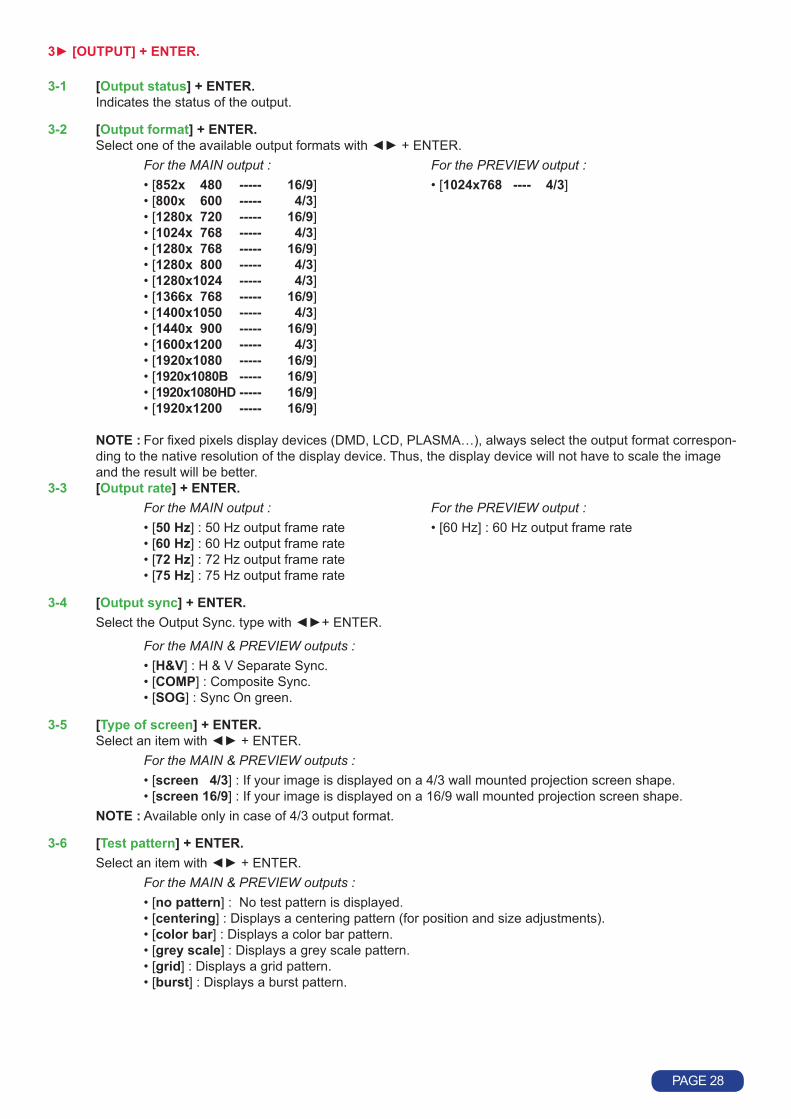
5 [LOGOS/FRAME] + ENTER
5-1 [Use logo] + ENTER. Selectanitemwith+ENTER. 5-1-1 [Display] + ENTER. ThisfunctionallowsturningONorOFFtheassignedlogosofeachinput.Selectaninputwithandpress
ENTERtoselectONorOFF. NOTE : To display a logo the output format should be the same as the one used during the storing. 5-1-2 [Assignment] + ENTER. This function allows assigning the stored logos to an input (up to 2 logos simultaneously). ①Selectaninputwith+ENTER. ②SelecttheINDEX1orINDEX2with+ENTER. ③Thenselectalogoornonewith+ENTER. 5-1-3 [Position] + ENTER. Adjust the logo position with H & V position functions. 5-1-4 [Transparency] + ENTER. This function allows adjusting the logo transparency. 5-1-5 [Fade duration] + ENTER. ThisfunctionallowsadjustingthefadedurationofthelogowhenyouturnONorOFFalogo.Adjustthedura-
tionwithandvalidatewithENTER.
5-2 [Record logo] + ENTER. This mode allows storing up to 8 logos in order to key them on the displayed image (up to 2 logos simulta-
neously).Selectanitemwith+ENTER. 5-2-1 [H position] + ENTER. AdjusttheHorizontalpositionofthelogoareawith+ENTER. 5-2-2 [V position] + ENTER. AdjusttheVerticalpositionofthelogoareawith+ENTER. 5-2-3 [H size] + ENTER. AdjusttheHorizontalsizeofthelogoareawith+ENTER. 5-2-4 [V size] + ENTER. AdjusttheVerticalsizeofthelogoareawith+ENTER. NOTE : The logo area is limited to one eighth (1/8) of the displayed area. 5-2-5 [Luma key level] + ENTER. Thisfunctionallows“erasing”thedarkestportionofyourlogoareainordertomakespeciallogocontour. Adjustthelumakeylevelwith+ENTER. 5-2-6 [Back. Color] + ENTER. Thisfunctionallowscoloringthe“erasedportions”ofthelogowhenusingthelumakey.Selectalevelwith
+ENTER. 5-2-7 [Store] + ENTER. Thisfunctionallowsstoringthelogointooneofthe8memories.Selectalogomemorywith+ENTER.The
memorization will take few seconds.
5-3 [Record anim] + ENTER. This mode allows storing an animated logo in order to key them into the displayed image. Select an item with
+ENTER. 5-3-1 [H position] + ENTER. AdjusttheHorizontalpositionofthelogoareawith+ENTER. 5-3-2 [V position] + ENTER. AdjusttheVerticalpositionofthelogoareawith+ENTER. 5-3-3 [H size] + ENTER. AdjusttheHorizontalsizeofthelogoareawith+ENTER. 5-3-4 [V size] + ENTER. AdjusttheVerticalsizeofthelogoareawith+ENTER. NOTE : The logo area is limited to one eighth (1/8) of the displayed area.
PAGE 31

5-3-5 [Luma key level] + ENTER. Thisfunctionallows“erasing”thedarkestportionofyourlogoareainordertomakespeciallogocontour.Ad-
justthelumakeylevelwith+ENTER. 5-3-6 [Back. Color] + ENTER. Thisfunctionallowscoloringthe“erasedportions”ofthelogowhenusingthelumakey.Selectalevelwith
+ENTER. 5-3-7 [Recording time] + ENTER. Adjusttherecordingtimewith+ENTER. 5-3-8 [Store] + ENTER. This function allows storing the logo into the memory. The memorization will take few seconds.
5-4 [Record frame] + ENTER. This mode allows storing up to 4 frames in order to display them at any time during the show. 5-4-1 [H position] + ENTER. AdjusttheHorizontalpositionoftheframeareawith+ENTER. 5-4-2 [V position] + ENTER. AdjusttheVerticalpositionoftheframeareawith+ENTER. 5-4-3 [H size] + ENTER. AdjusttheHorizontalsizeoftheframeareawith+ENTER. 5-4-4 [V size] + ENTER. AdjusttheVerticalsizeoftheframeareawith+ENTER. 5-4-5 [Luma key level] + ENTER. Thisfunctionallows“erasing”thedarkestportionofyourframeinordertomakespecialframecontour.Adjust
thelumakeylevelwith+ENTER. 5-4-6 [Store] Thisfunctionallowsstoringthedisplayedimage(frame)intoaoneofthe4memories.PressesENTERtostart
the memorization of the frame. The memorization will take about 2 minutes.
5-5 [Erase logo] + ENTER. Thisfunctionallowserasingthememorizedlogos.Selectanitemwith+ENTER.
5-6 [Erase frame] + ENTER. Thisfunctionallowserasingthememorizedframes.Selectanitemwith+ENTER.
PAGE 32

6[EFFECT]
This menu allows storing an effect in each of the effect buttons (EFFECT PRESET). ① First select an effect button with LCD menu or with the front panel button. ② Then select one of the following effects:
6-x-1 [Cut] :allowsswitchingseamlesslythepre-selectedinputontotheMAINoutput.
6-x-2 [Fading] :allowsfadingthepre-selectedinputtotheMAINoutput.Youcanselectthedurationofthetransition as indicated below :
• [1s] : 1 second transition. • [3s] : 3 second transition. • [5s] : 5 second transition. •[Custom]:Selectadurationfrom0.5secondupto25secondsby0.5secondsteps.
6-x-3 [Title] :AllowsoverlayingatitleontheMAINoutput.Thetitleshouldbecreatedusingsoftwaresuchas PowerPoint : the text should be bright (yellow, white) on a black background. A shadow bar is also available for increasing the readability of the text on bright images
① Select the [duration]ofthetransitionwith+ENTER between : • [holding] : The text appears after pushing on the TAKE button, and will be removed only by a second
push on the TAKE button. • [3s] : 3 second transition. • [5s] : 5 second transition. • [custom]:Selectadurationfrom0.5secondupto25secondsby0.5secondsteps. ② Select the [Size]oftheshadowbarwith+ENTER. ③ Select the vertical [Position]oftheshadowbarwith+ENTER. ④ Select the [Intensity]oftheshadowwith+ENTER. ⑤ Select the [Effect opening] and the [effect closing] of the title between [Cut] & [Fade]with+ENTER.
6-x-4 [PIP] : Allows displaying a picture into another picture. The PREVIEW image is reduced and displayed ontotheMAINimage.
① Select the [duration]ofthetransition,andvalidatewithENTER. • [holding] : The PREVIEW image appears after pressing on the TAKE button, and will be removed only
by a second push on the TAKE button. • [3s] : 3 second transition. • [5s] : 5 second transition. • [custom]:Selectadurationfrom0.5secondupto25secondsby0.5secondsteps. ② Adjust the [Image size] of the PIP with H and V, and validate with ENTER. ③ Set the horizontal and vertical [Image position] of the PIP with the H and V knob, and validate with
ENTER. ④ Adjust the [Window size] of the PIP with the H and V knob, and validate with ENTER. This function
allows, for example, cutting the black bars of a letterbox source. ⑤ Adjust the [Window position] of the PIP with the H and V knob, and validate with ENTER. ⑥ Select the [Effect opening] and the [effect closing] of the PIP between [Cut] & [Fade] with
+ ENTER.
PAGE 33

7 [AUDIO MAIN] + ENTER.
7-1 [Master volume] + ENTER. Adjusttheaudiooutputlevelwith+ENTER.
7-2 [Audio mode] + ENTER. Selecttheoutputaudiomodewith+ENTER. • [Mono] : Set the output in mono mode. • [Stereo] : Set the output in stereo mode.
7-3 [Audio source] + ENTER. Selectanitemwith+ENTER: • [auto follow] : The audio follows the video image. • [input --] : The selected audio input is permanently diffused.
7-4 [Audio level] + ENTER. Thisfunctionallowstoseparatelyadjustthelevelofeachaudioinput.Adjustthelevelwith+ENTER. NOTE : This function acts on the selected (diffused) audio input.
7-5 [Audio balance] + ENTER. Thisfunctionallowsadjustingforeachinputtheaudiobalance.Adjustthelevelwith+ENTER. NOTE : This function acts on the selected (diffused) audio input.
7-6 [AUX input] + ENTER.
7-7 [Mute off] + ENTER. SwitchONorOFFtheaudiooutput.ValidatewithENTER.
8 [AUDIO PRELIST] + ENTER.
8-1 [Master volume] + ENTER. Adjusttheaudiooutputlevelwith+ENTER.
8-2 [Audio mode] + ENTER. Selecttheaudiomodeoftheoutputwith+ENTER. • [Mono] : Set the output in mono mode. • [Stereo] : Set the output in stereo mode.
8-3 [Audio source] + ENTER. Selectanitemwith+ENTER: • [auto follow] : The audio follows the video image. • [input --] : The selected audio input is permanently diffused.
8-4 [Audio level] + ENTER. Thisfunctionallowstoseparatelyadjustthelevelofeachaudioinput.Adjustthelevelwith+ENTER. NOTE : This function acts on the selected (diffused) audio input.
8-5 [Audio balance] + ENTER. Thisfunctionallowsadjustingforeachinputtheaudiobalance.Adjustthelevelwith+ENTER. NOTE : This function acts on the selected (diffused) audio input.
8-6 [AUX input] + ENTER.
8-7 [Mute off] + ENTER. SwitchONorOFFtheaudiooutput.ValidatewithENTER.
PAGE 34
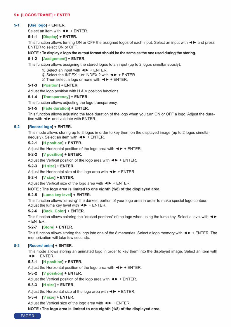
9[CONTROL] + ENTER.
9-1 [Versions] + ENTER. Version _._= update version. I1toI4=Identificationnumber. K,A,B,C,O=statusoftheinternalfirmwareversions.
9-2 [Transition] + ENTER. Selectanitemwith+ENTER 9-2-1 [Fade color] + ENTER. This function allows selecting the color of the frame during the fade through frame transition. Select
acolor(red,greenandblue)with+ENTERandadjustthelevelwith+ENTER. During the adjustment the color is displayed on the output. To obtain black, set the 3 levels to minimum. To obtain white, set the 3 levels to maximum. To obtain grey, set the 3 levels in the middle.
9-2-2 [Clean cut] + ENTER. This function allows a clean switching thanks to a fast freeze of the displayed source. Select a function
with+ENTER. •[fromcomputer]:TheCLEANCUToperatesonlywhenswitchingfromacomputersource.Switching
from the source operates with a fade color. •[fromvideo]:TheCLEANCUToperatesonlywhenswitchingfromavideosource.Switchingfromthe
source operates with a fade color. •[fromall]:TheCLEANCUToperateswhenswitchingfromanysource. 9-2-3 [Fade frame] + ENTER. This function allows switching by a fading through a frame (instead of a color). Select a frame and adjust
thedurationofthetransitionwith+ENTER.
9-3 [Sync loss] + ENTER. Allowstodisplayaframeorasourceincaseofsync-lossoftheselectedinput.Selectanitemswith+ENTER
9-4 [RS232/LAN port] + ENTER. Selectthecommunicationportwith+ENTER. • [RS232] : Enables the RS-232 communication port. (Default setting). • [LAN]: EnablestheLANcommunicationport. IMPORTANT : To avoid address conflicts, configure the LAN communication port (with the LAN setup
menu) before activating it. NOTE : The RS-232 & the LAN communication ports can not be used simultaneously.
9-5 [LAN setup] + ENTER. AllowsconfiguringtheLANcommunicationport.SelecttheUDPorTCPprotocolwith+ENTER then select
itemswith+ENTER. • [device addr.] : Every device connected to an IP network must have a unique IP address. This address is used
toreferencethespecificunit.IPaddressesarespecifiedasx.x.x.xwhereeachxisanumberfrom1to254.AssignthedevicetoauniqueIPaddresswith+ENTER. (Default value: 192.168.0.2).
• [remote addr.] : This is the destination IP address used with an outgoing connection. Select the destination IP addresswith+ENTER.(Defaultvalue:192.168.0.1).
• [gateway addr.] :Thegatewayaddress,orrouter,allowscommunicationwithotherLANsegments.Thega-tewayaddressshouldbetheIPaddressoftherouterconnectedtothesameLANsegmentastheunit.Selectthegatewayaddresswith+ENTER.(Defaultvalue:192.168.0.1).
• [device port] :EveryTCPconnectionandeveryUDPdatagramisdefinedbyadestinationIPaddressandaportnumber.Selectalocalportnumberwith+ENTERbetween10000and10999.(De-faultvalue:10500).
• [remote port] : You must set the remote TCP port number for the unit to make outgoing connections. This pa-rameterdefinestheportnumberonthetargethosttowhichaconnectionisattempted.Selectaremoteportnumberwith+ENTERbetween00000and655000.(Defaultvalue:10500).
• [netmask] : AnetmaskdefinesthenumberofbitstakenfromtheIPaddressthatareassignedforthehostsection. The device prompts for the number of host bits to be entered, then calculates the netmask, which displays in standard decimal-dot notation when the saved parameters are dis-played.Selectthenetmaskwith+ENTER.(Defaultvalue:255.255.255.0).
• [default setup] :SetalltheLANsettingstodefaultvalue.Select[YES]andvalidatewithENTER.
PAGE 35

MAC address : The MAC address, also referred to hardware address, is a unique number assigned to each device. The MAC address is available on the bottom device label.
9-6 [key locking] + ENTER. SelectanitemwithandchangethemodewithENTER. • [All] : Locks/unlocks all the front panel switches. • [Menus]:Locks/unlockstheLCDCONTROLswitches. • [autolock] : Allows selecting an input only if a signal is connected. • [Input]:Locks/unlockstheINPUTSELECTIONandFREEZEswitches. NOTE : To unlock press simultaneously ENTER and EXIT.
9-7 [Stand-by] + ENTER.
9-7-1 [Baud rate] + ENTER. Selectthebaudrateofthedisplaydevicewith+ENTER(9600,2400&1200). 9-7-2 [Message ON] + ENTER. ThisfunctionallowstostoretheONmessageofyourdisplaydevice.Whenveryourdevicegoesoutofstand-by
modeitwillsendthestoredmessagetoyourdisplaydevice.TheONmessagecanbecomposedofupto50bytes.Foreachbyte,selecttheneededASCIIcodewithandvalidatewithENTER.
NOTE : The 0 value allows to display : no data. 9-7-3 [Message OFF] + ENTER. This function allows to store the OFF message of your display device. Whenver your device goes out of stand-
by mode it will send the stored message to your display device. The OFF message can be composed of up to 50bytes.Foreachbyte,selecttherequiredASCIIcodewith,thenpressENTER.
NOTE : The 0 value allows to display: no data. 9-7-4 [Reset mess ON] + ENTER. AllowstoresettheONmessage. 9-7-5 [Reset mess OFF] + ENTER. Allows to reset the OFF message. 9-7-6 [Stand by time] + ENTER. Whenthedevicedoesn'tdetectanysignalontheselectedinput,itsetsitselftoSTANDBYmodeafterthedura-
tionofyourchoice.Selectadurationwith+ENTER. NOTE : Select OFF to inactivate this function. 9-7-7 [Stand by] + ENTER. AllowstosetthedevicetoSTANDBYmode.TogetoutofSTANDBYmode,pressoneofthefrontpanelbuttons.
9-8 [Erase memories] + ENTER. ThisfunctionallowserasingallNON-volatileimagememories.Select[YES]andvalidatewithENTER.
9-9 [Default value] + ENTER. This function allows setting the following functions to the factory settings. Select [YES]andvalidatewithENTER.
FUNCTION POSITIONinput type Computer HV/C.used input All used.H sync load All Hi-Z.VCR mode All offoutputformat SXGA60Hz4/3.Output sync H&V.type of screen 4/3test pattern noswitching seamless #1pos.settings 0aspect ratio in 4/3 aspect ratio out 1:1brightness 128black level 128contrast 128color 128hue 128under/overscan overscansharpness 3mastervolume 192audio source auto followaudio level 48audio balance 32auxiliary input OFFmute OFFdisplaylogo allONassignment all nonekey locking all unlockfadecolor R,G,B=0RS232/LANport RS232
PAGE 36

UPDATING THE DEVICE
ThedevicecanbeupdatedviatheRS232communicationportorviaLANcommunicationportacomputer(PC).
1) SwitchONthedevice.2) Openthefile:OctoValueUpdater(inStart>Program>ANALOGWAY>OctoValueUpdater).3) Click on the Port menu and select setup : the Communication setup window open. - If you use the RS232 port : Select RS232 and the Com port connected to the device. -IfyouusetheLANPort:SelectUDPorTCPandselectthecommunicationparameters.4) Click on START on the software. The update will start.5) When the software displays : Program operation completed, click on the Quit button to close the update
software. Your device is now ready to work.
1) Connect the device to an AC power outlet.2) SwitchONthedevice(REARPANELSWITCH=I).3) Connect the device to the computer used for the update via the desired communication port. - For the RS232 communication port : Connect the RS232 connector of the device to the serial port of your
computerwithaDB9M/Fstraightcable. -FortheLANcommunicationport:ConnecttheRJ45connectorofthedevicetoyournetworkaccordingto
yourinstallation.ThenwiththefrontpaneldisplaymenuconfiguretheLANcommunicationport(CONTROL>LANsetup)andactivatetheLANcommunicationport(CONTROL>RS232/LANport>LAN).
6-1. INTRODUCTION
6-2. CONNECTION
6-3. UPDATE INSTRUCTIONS
NOTE : The updater files are available on our web site : http://www.analogway.com
PAGE 37

REMOTE CONTROL SOFTWARE
Your device is shipped with a Windows compatible Remote Control Software. This software allows you to control and make all adjustments by a simple mouse click.
NOTE : Preferably use Windows NT, 2000 or XP for LAN operation.
① CONNECTING TO THE RS232 PORT : -ConnecttheserialportofyourcontroldevicetotheRS232port(DB9Femaleconnector)ofthedevicewitha
straightcable(DB9Female/DB9Male). - Speed transmission :9600bauds,8databits,1stopbit,noparitybit,noflowcontrol. - Pin-out :
PIN # FUNCTIONS
2 TRANSMITDATA(Tx) 3 RECEIVE DATA (Rx) 5 GROUND(Gnd)
② CONNECTING TO THE LAN PORT : -ConnecttheLANport(RJ45connector)ofthedevicetoyournetworkaccordingtoyourinstallation.
① TurnyourcomputerONandwaitforWindowstocompletelystart.② InserttheCD-ROMintoyourdrive:theANALOGWAYhomewindowwillopenautomatically.③ SelectthelanguageoftheCD-ROMmenus,thenclickon“InstallaRemoteControlSoftware”andselectthe
name of your device.IMPORTANT : If the Autorun is not enabled : From the Windows desktop, open My Computer and select the
CD-ROM drive. Select the Autorun folder, and then select the autorun.exe file.④ Follow the Windows installation instructions.
7-1. CONNECTIONS
7-2. SOFTWARE INSTALLATION
7-3. COMMUNICATION SETUP
DB9female(Rearpanel of the device)
① ConnecttheRS232orRJ45cablebetweenthedeviceandthecontroldeviceasindicatedinthesection7-1.② ThenpowerONallofthedevices.③ ClickontheprogramfilesOctoValueinStart>program>ANALOGWAY>OctoValuetorunthesoftware.④ ClickonControlmenuandselectRS232/LANsetup,then: • CASE OF RS232 PORT : -Withthefrontpaneldisplaymenuofthedevice,verifythattheRS232portisactivated(CONTROL>RS232/
LANport>RS232). -WiththeControlmenuofthesoftware,selectRS232/LANsetup,thenselectRS232andselecttheCOMport
numbercorrespondingtotheconnectionofthedeviceinthePortfield.
If the communication is OK, the message "Device connected" is displayed as well as the model in the windows title bar.
PAGE 38

• CASE OF LAN PORT : -With the front panel displaymenu of the device, verify the configuration of the LAN communication port
(CONTROL>LANsetup),thenactivatetheLANcommunicationport(CONTROL>RS232/LANport>LAN). -WiththeControlmenuofthesoftware,selectRS232/LANsetupandLANSetup.ThenconfiguretheLocal
port, the Remote IP address and the Remote port and click on Apply to setup the new values. The software will also display Device connected.
① Click on the Settings button (left bottom of the window) to display the Settings window.② Click on the Input Settings tab and select the Signal Type for each input. Then make the other adjustments
(video Standard...).
7-4. USING THE SOFTWARE
③ Click on the Output tab, then select the Switching mode (internal rate, input #- rate, or seamless), then select the desired adjustment (output sync, output format, output rate...).
PAGE39

④ Click on the Image tab and adjust your input.
⑤ Click on the Audio tab and select Automatic (follow switching mode) or an Audio source (breakaway mode). Then adjust the Level and the Balance of each audio source.
PAGE40
7-5. Frames and Logos Loader
The RCS provides additional functionality. It can download logos, animated logo or frames via the RS-232 or Ethernet(LAN).ThisfeaturealsoallowsdownloadingalogoanimatedinGIFformat.Todowloadlogos,itisrecommendednottoexceed1/8thofthefinalsizeoftheoutputimageMain.Supportedformatsare:JPEG,BMP,GIF,JPG,ICO,EMF,WMF.

TECHNICAL SPECIFICATIONS
• ANALOG COMPUTER Connectors : HD15 (inputs #2 to 8) and DVI-I (input #1).Linefrequency: Upto110kHz.Framefrequency: Upto130Hz.Resolution: Upto1600x1200/60Hz.Sync. types : RGBHV, RGB/S, RGsB (Sync On Green).Levels: R,G,B=0.7Vp/p. H & V Sync = TTL CompositeSync=TTLand0.3V. SOG(SyncOnGreen)=0.3V.Impedance : R, G, B = 75 ohms. H = 75 ohms or Hi-Z. V = Hi-Z.
• DIGITAL COMPUTER INPUT Connectors : DVI-I (input #1).Format : Digital Visual Interface (DVI) TMDS single link.Resolution : Upto1600x1200/60HzRB(reducedblanking)and1920x1080/60Hz.
• RGB/S VIDEOConnectors : HD15 (inputs #2 to 8) and DVI-I (input #1).Frequency: 15.625kHz/50Hz(625lines). 15.734kHz/60Hz(525lines).Levels: R,G,B=0.7Vp/p. SYNC.=0.3Vp/porTTL.Impedance : RGB = 75 ohms. SYNC. = 75 ohms or Hi-Z.
• COMPONENTConnectors : HD15 (inputs #2 to 8) and DVI-I (input #1).Frequency: 15.625kHz/50Hz(625lines). 15.734kHz/60Hz(525lines).Levels: Y=1Vp/p(0.7VLuma+0.3VSync.). R-Y=0.7Vp/p. B-Y=0.7Vp/p.Impedance : Y, R-Y, B-Y = 75 ohms.
• HDTV Connectors : HD15 (inputs #2 to 8) and DVI-I (input #1).Formats: HD-YUV(1080i/60-50Hz,1080p,720p/60-50Hz,480p/60Hz).Levels: Y=1Vp/p(0.7V+sync.). R-Y=1Vp/p(0.7V+sync.). B-Y=1Vp/p(0.7V+sync.).Sync.: Tri-level:±0.3V(positive/negative). Bi-level:0.3V(negative).Impedance : 75 ohms.
• S.VIDEO Connectors : 4-pin miniDIN(input#8),BNC(input#4),HD15(inputs#2to8)andDVI-I(input#1).Standards: PAL(15.625kHz/50Hz–625lines)orNTSC(15.734kHz/60Hz–525lines).Levels : Y = 1 Vp/p. C=0.3Vp/p.Impedance: 75 ohms.
• COMPOSITE VIDEOConnectors: BNC (input #4), RCA (input #8), HD15 (inputs #2 to 8) and DVI-I (input #1).Standards: PAL/SECAM(15.625kHz/50Hz–625lines)orNTSC(15.734kHz/60Hz–525lines).Level : 1 Vp/p.Impedance : 75 ohms.
8-1. COMPUTER & VIDEO INPUTS
PAGE 41

8-2. DISPLAY OUTPUTS
8-3. AUDIO INPUTS
8-4. MAIN AUDIO OUTPUT
8-5. PRELIST AUDIO OUTPUT
• MAIN ANALOG Connectors : HD15 and DVI-I (2x buffered).Resolution: 4/3&5/4:800x600,1024x768,1280x1024,1400x1050,1600x1200. 16/9&16/10:852x480,1280x720,1280x768,1366x768,1920x1080.Framefrequency: 50,60,72***,75***Hzandfollow(*** = not available for all resolutions).Sync. types : RGBHV, RGB/S, RGsB (Sync On Green).Levels: R,G,B=0.7Vp/p. H & V Sync = TTL CompositeSync=TTLand0.3V. SOG(SyncOnGreen)=0.3V.Impedance : R, G, B = 75 ohms.
• MAIN DIGITAL Connector : DVI-I.Format : Digital Visual Interface (DVI). TMDS Single link.Resolution : Upto1600x1200@60Hz.
• PREVIEW Connectors : HD15.Format: XGA/60Hz.Sync. types : RGBHV.Levels: R,G,B=0.7Vp/p. H & V Sync = TTL Impedance : R, G, B = 75 ohms.
Connectors: Jack 3.5 mm (inputs #1) and MCO (inputs #2, 3 & 4).Type : Stereo unbalanced.Levels : Vi = + 18 dBu (max). Zi=20kΩunbalanced. Zi=40kΩbalanced.Gain : Adjustable.
Connectors : MCO.Type : Stereo balanced & unbalanced.Levels : Vo = + 18 dBu max (unbalanced). Zo=300Ω(unbalanced). Vo = + 24 dBu max (balanced). Zo=600Ω(balanced).Gain: 0dB nominal (adjustable with Master volume).
Connectors: Jack 3.5 mm.Type : Unbalanced.Levels : Vo = + 18 dBu max. Zo=300Ω.Gain: 0dB nominal (adjustable with Master volume).
PAGE 42

8-6. COMMUNICATION PORTS
8-7. TRIGGER
8-8. ENVIRONMENTAL
• RS232 (on DB9 female connector)DataRate: 9600Bauds,8databits,1stopbit,noparitybit,noflowcontrol.
Pin-out : PIN # FUNCTIONS 2 Tx1 (transmit data to the control device) 3 Rx1 (receive data from the control device) 4 Rx2 (receive data from the display device) 5 GROUND(Gnd) 8 Reserved for manufacturer. 9 Tx2 (transmit data to the display device)
• LANProtocol : TCP (Transmission Control Protocol) / UDP (User Datagram Protocol).DataRate: 10/100Mbps.
LEDfunctions(onRJ45connector): Left LED Right LED Meaning
OFF OFF Nolink OFF ON 100BASE-Tlink. ON OFF 10BASE-Tlink.
Connector: Jack3.5mmfemale.Command levels : ON = + 12 Vdc trigger. OFF=0Vdc.OutputCurrent: 0.1Amaxat+12Vdc.
NOTE : This output is activate with the AC Power Switch (ON/OFF).
PowerSupply: InternalCE/UL/CSA/IEC950(50W),universal,automatic. Input:100VACto250VAC;50-60Hz;I=1AMax.StorageTemperature: -40°Cto+70°C(-40°Fto+158°F).Operatingtemperature: 0°Cto+50°C(32°Fto122°F).Hygrometry: 10%to80%(withoutcondensation).Dimensions: D265xW482xH44mm/D10.4”xW19”xH1.74”. Compatiblewiththe19”rack(height=1unit).Weight : 3.5 kg / 7.7 lbs.
+ 12 VdcGround
Jack 3.5 connection
PAGE 43

APPENDIX : PROGRAMMER’S GUIDE
A. INTRODUCTION
B. COMMANDS STRUCTURE
C. ERROR RESPONSES
IfyouneedtouseyourownSoftwareControlprogramfromaPCorWORKSTATIONwithanRS232port,thedeviceallows communication through an ASCII code protocol.The device treats any character that it receives on the RS-232 as a possible command but only accepts legal com-mands. There is no starting/ending code needed in a command string.A command can be a single character typed on a keyboard and does not require any special character before or after it.(Itisnotnecessarytopress"ENTER"onthekeyboard).Acommandcanbeprecededbyavalue(SeechapterB).When the device receives a valid command, it will execute the command. Then it will send back the status of the para-meters that have changed due to this command. If the command cannot be executed (value out of range, no signal on the selected input), the device will just sends back the current status of the corresponding parameters.If the command is invalid, an error response will be returned to the control device. All responses returned to the control deviceendwithacarriagereturn<CR>andalinefeed<LF>signalingtheendoftheresponsecharacterstring(seechapter C).
Commands are usually composed of a numerical value followed by the command character. The characters used wi-thout any numerical value return the current setting of the command.Command = Value (optional) + Character.
Command Response DescriptionValue Character none FY OSYN Readtheoutputsynctype.
10 V VP10 SetVerticalpositionto10.
Examples :
When the device receives from the control device an invalid command or value, it returns an error response :
Command Response DescriptionValue Character none z E10 Invalidcommand.
70260 H E13 Invalidvalue.
PAGE 44

D. COMMANDS AND RESPONSES TABLE
CD RESPONSE COMMAND DESCRIPTION TYPE VALUE MIN MAX DESCRIPTION
SELECTION COMMANDSCC CC MAINselectedinput. Rd 0 12 1=input#1 2=input#2CN CN Backgroundselection(PIPeffectonly) Rd/Wr 0 8 3=input#3 4=input#4cc cc PREVIEWselectedinput(readonly). Rd 0 8 5=input#5 6=input#6cn cn Inputpre-selectionorPIPswitching Rd/Wr 0 8 7=input#7 8=input#8 9=frame#1 10=frame#2 11 = frame #3OB OB BlackscreenontheMAINoutput Rd/Wr 0 1 1=blackoutputob ob BlackscreenonthePREVIEWoutput Rd/Wr 0 1 1=blackoutputTK TK TAKE(transition). Rd/Wr 0 1 1=startthetransition(automaticresetattheendofthe
effect duration). 0=stopthetransition(forholdingeffect).TV TV Transitionavailability. Rd 0 1 1=Newinputreadytocommute.FZ FZ FREEZEMAIN. Rd/Wr 0 1 0=inactive 1=active.fz fz FREEZEPREVIEW. Rd/Wr 0 1 0=inactive 1=active.
INPUT COMMANDSPC PC Inputselectionforadjustment. Rd/Wr 0 8 0=allinputs. 1=input#1.... 8=input#8PE PE Inputdisabling(workswithPC) Rd/Wr 0 1 0=disable 1=enable.PL PL Hsyncloadselection(workswithPC). Rd/Wr 0 1 0=Hi-Zload 1=75Ωload.PR PR RGB input type selection (workswithPCcommand). Rd/Wr 0 10 0=composite 1=S.VIDEO 2 = YUV 3 = RGBS (TTL) 4 = RGsB (SOG) 5 = RGBS (ana) 6 = computer (SOG) 7 = comp (HV or C.) 8=computerDVI 9=HDTVYUV 10=audioonlyPI PI Input standard selection (workswithPCcommand). Rd/Wr 0 4 0=NTSC/PAL/SECAM. 1=NTSC. 2=PAL. 3 = SECAM 4 = Black & White.PP PP VCRmode Rd/Wr 0 1 0=OFF 1=ON.
OUTPUT COMMANDSXR XR Switchingmodeselection. Rd/Wr 0 10 0=internalrate 1=followinput#1 2 = follow input #2... 8 = follow input #8 9=seamless#1 10=seamless#8OF OF Outputformatsselection. Rd/Wr 0 9 0=800x6004/3 1=1024x7684/3 2=1280x10244/3 3=1400x10504/3 4=1600x12004/3 5=852x48016/9 6=1280x72016/9 7=1280x76816/9 8=1366x76816/9 9=1080p16/9OR OR Outputrateselection. Rd/Wr 0 3 0=50Hz1=60Hz 2 = 72 Hz 3 = 75 HzOY OY Outputsyncselection(M). Rd/Wr 0 2 0=H&Vsync. 1=Compositesync.oy oy Outputsyncselection(P). Rd/Wr 0 2 2=SOGOS OS Typeofscreenselection Rd/Wr 0 1 0=4/3screen 1=16/9screenOP OP Testpatternselection(M). Rd/Wr 0 5 0=nopattern 1=centering 2=colorop pop Testpatternselection(P). Rd/Wr 0 5 3=greyscale 4=grid. 5=burst
NOTE : (M) = MAIN output. Rd/Wr = Read and write command. (P) = PREVIEW output. Rd = Read only command.
PAGE 45

CD RESPONSE COMMAND DESCRIPTION TYPE VALUE MIN MAX DESCRIPTION
IMAGE COMMANDS
yC yC Automaticcentering(M). Rd/Wr 0 1 1=centeringaction(automaticreset).HP HP Horizontalposition(M). Rd/Wr 0 255VP VP Verticalposition(M). Rd/Wr 0 255HW HW Horizontalsize(M). Rd/Wr 0 255VS VS Verticalsize(M). Rd/Wr 0 255BR BR Brightnessadjustment(M). Rd/Wr 0 255CT CT Contrastadjustment(M). Rd/Wr 0 255CL CL Coloradjustment(M). Rd/Wr 0 255HU HU Hueadjustment(M). Rd/Wr 0 255QP QP Sharpnessadjustment(M). Rd/Wr 0 7 0=level1... 7=level8.OV OV Underscan/overscan(M) Rd/Wr 0 1 0=underscan 1=overscanIA IA Inputaspectratioselection(M) Rd/Wr 0 2 0=4/3 1=16/9 2=16/9anamorphicOA OA Outputaspectratio(M) Rd/Wr 0 3 0=1:1 1=crop 2=Fullscreen 3=zoom.ZW ZW Zoom:horizontalsize(M). Rd/Wr 10 200 10=10% 100=100%(nozoom) 200=200%ZS ZS Zoom:verticalsize(M). Rd/Wr 10 200 10=10% 100=100%(nozoom) 200=200%ZH ZH Zoom:horizontalposition(M). Rd/Wr 0 255ZV ZV Zoomverticalposition(M). Rd/Wr 0 255QR QR Redleveladjustment(M) Rd/Wr 0 255QG QG Greenleveladjustment(M) Rd/Wr 0 255QB QB Bleuleveladjustment(M) Rd/Wr 0 255MC CLK Numberofpixelsperline(M) Rd/Wr 0 65535MP PHA Pixelsphaseadjustment(M) Rd/Wr 0 31yP yP PRESET(M). Rd/Wr 0 1 1=PRESETaction(automaticreset).yc yc Automaticcentering(P). Rd/Wr 0 1 1=centeringaction(automaticreset).hp hp Horizontalposition(P). Rd/Wr 0 255vp vp Verticalposition(P). Rd/Wr 0 255hw hw Horizontalsize(P). Rd/Wr 0 255vs vs Verticalsize(P). Rd/Wr 0 255br br Brightnessadjustment(P). Rd/Wr 0 255ct ct Contrastadjustment(P). Rd/Wr 0 255cl cl Coloradjustment(P). Rd/Wr 0 255hu hu Hueadjustment(P). Rd/Wr 0 255qp qp Imageprocessadjustment(P) Rd/Wr 0 7 0=level1... 7=level8.ov ov Underscan/overscan(P) Rd/Wr 0 1 0=underscan 1=overscania ia Inputaspectratioselection(P) Rd/Wr 0 2 0=4/3 1=16/9 2=16/9anamorphicoa oa Outputaspectratio(P) Rd/Wr 0 3 0=1:1 1=crop 2 = Full screen 3 = zoom.zw zw Zoomhorizontalsize(P). Rd/Wr 0 255 0=100% 255=200%zs zs Zoomverticalsize(P). Rd/Wr 0 255 0=100% 255=200%zh zh Zoomhorizontalposition(P). Rd/Wr 0 255zv zv Zoomverticalposition(P). Rd/Wr 0 255qr qr Redleveladjustment(P) Rd/Wr 0 255qg qg Greenleveladjustment(P) Rd/Wr 0 255qb qb Bleuleveladjustment(P) Rd/Wr 0 255mc mc Numberofpixelsperline(P) Rd/Wr 0 65535mp mp Pixelsphaseadjustment(P) Rd/Wr 0 31yp yp PRESET(P). Rd/Wr 0 1 1=PRESETaction(automaticreset).YS YS STORE. Rd/Wr 0 1 1=STOREaction(automaticreset).
NOTE : (M) = MAIN output. Rd/Wr = Read and write command. (P) = PREVIEW output. Rd = Read only command.
PAGE 46

CD RESPONSE COMMAND DESCRIPTION TYPE VALUE MIN MAX DESCRIPTION
EFFECTS COMMANDSEF EF Effectselection. Rd/Wr 0 4 0=CUT. 1=FADING. 2 = TITLE. 4 = PIP.ED ED Effectdurationselection. Rd/Wr 5 255 5=0.5second 244=24.5seconds 255 = holdingea ea Horizontalpositionoftheeffect. Rd/Wr 0 255eb eb Verticalpositionoftheeffect Rd/Wr 0 255ec ec Horizontalsizeoftheeffect Rd/Wr 0 255 0=PIP1:1 5=sizemini 255 = size maxied ed Verticalsizeoftheeffect. Rd/Wr 0 255 0=PIP1:1 5=sizemini 255 = size maxiee ee Windowhorizontalposition(PIP). Rd/Wr 0 255ef ef Windowverticalposition(PIP). Rd/Wr 0 255eg eg Windowhorizontalsize(PIP). Rd/Wr 0 255eh eh Windowverticalsize(PIP). Rd/Wr 0 255eO eO Effectoptions Rd/Wr 0 5 0=without 1=shadow 2 = smooth 3 = edgeei ei Effectoptionsparameters(size,shadow...). Rd/Wr 0 255 0=sizemini 255=sizemaxi.ej ej Effectoptionsparameters(color). Rd/Wr 0 255EO EO Effectopeningtype. Rd/Wr 0 1 0=Cut 1=fadeEC EC Effectclosingtype. Rd/Wr 0 1 0=Cut 1=fadeEo Eo Effectopeningduration(0.1secstep) Rd/Wr 0 255Ec Ec Effectclosingduration(0.1secstep) Rd/Wr 0 255TO TO Effectinprogress. Rd 0 1 0=noeffectinprogress. 1 = effect in progress.AUDIO COMMANDS AC AC AudiosourceselectionoftheMAIN. Rd/Wr 1 8 1=audiosource#1...8=audiosource#8.ac ac Audio source selection of the PRELIST output. Rd/Wr 1 8 1 = audio source #1... 8 = audio source #8.AO AO AudiomodeoftheMAINoutput. Rd/Wr 0 1 0=autofollow 1=breakawayao ao AudiomodeofthePRELISToutput. Rd/Wr 0 1 0=autofollow 1=breakawayAV AV MatervolumeoftheMAINoutput. Rd/Wr 0 255 0=minimum 255=maximumav av MatervolumeofthePRELISToutput. Rd/Wr 0 255 0=minimum 255=maximumAT AT MuteoftheMAINoutput. Rd/Wr 0 1 0=muteOFF 1=muteONat at MuteofthePRELISToutput Rd/Wr 0 1 0=muteOFF 1=muteONAS AS Mono/stereomodeoftheMAINoutput. Rd/Wr 0 1 0=stereo 1=monoas as Mono/stereomodeofthePRELIST. Rd/Wr 0 1 0=stereo 1=monoAL AL Audiolevel(workswithPCcommand) Rd/Wr 0 64 0=minimum 1=maximumAB AB Audiobalance(workswithPC) Rd/Wr 0 64 0=lefttomaximum64=righttomaximumAX AXMU AuxiliarysourcetoMAIN. Rd/Wr 0 1 0=used 1=unused.ax axmu AuxiliarysourcetoPRELIST. Rd/Wr 0 1 0=used 1=unused.
NOTE : (M) = MAIN output. Rd/Wr = Read and write command. (P) = PREVIEW output. Rd = Read only command.
PAGE 47

CD RESPONSE COMMAND DESCRIPTION TYPE VALUE MIN MAX DESCRIPTION
FRAME & LOGOS COMMANDS
LM LM Frame/logomode. Rd/Wr 0 3 0=use&assignmentmode. 1 = logo recording mode. 2 = animated logo recording mode 3 = frame recording mode. 4 = erasing logo mode. 5 = erasing frame mode. 6 = logo transfer mode.LX LX Statusofthelogoprogrammer Rd 0 4 0=free. 1 = logo/frame in recalling process. 2 = logo/frame in storing process. 3 = output format incompatible with the logo. 4 = logo/frame in erasing process.LA LA Logoindex#1assignment. Rd/Wr 0 9 0=nologo 1 = logo 1... 8 = logo 8 9=animatedlogoLB LB Logoindex#2assignment. Rd/Wr 0 9LF LF Frameassignment. Rd/Wr 0 4 0=noframe 1 = frame 1 2 = frame 2 3 = frame 3 4 = frame 4LC LC • In logo recording mode : number of the logo to be store (1 to 8). • In frame recording mode : numberoftheframetobestore(1to4). Rd/Wr 0 8 Inerasemode:0=eraseall • In erase logo mode : number of the logo to be erase (1 to 8) • In erase frame mode : number of the frame to be erase (1 to 4). LD LD Displaylogo(accordingtoPCH) Rd/Wr 0 1 0=DisplayOFF 1=DisplayONLU LU Horiz.positionofthelogostoringarea. Rd/Wr 0 255Lu Lu Vert.positionofthelogostoringarea. Rd/Wr 0 255LK LK Horizontalsizeofthelogostoringarea. Rd/Wr 5 255 5=3% 255=100%Lk Lk Verticalsizeofthelogostoringarea. Rd/Wr 5 255 5=3% 255=100%LQ LQ Pixelsnumberinalineofthestoringarea.Rd 0 65535Lq Lq Linesnumberofthestoringarea. Rd 0 65535LH LH Horizontalpositionofthelogo1(M). Rd/Wr 0 255LV LV Verticalpositionofthelogo1(M). Rd/Wr 0 255LW LW Logo1horiz.size%outputformat(M). Rd 5 255 5=3% 255=100%LS LS Logo1vert.size%outputformat(M). Rd 5 255 5=3% 255=100%LT LT Logo1type(M). Rd 0 2 0=incrustinglogo 1 = cutting logo 2 = animating logoLP LP Pixelsnumberinalineoflogo1(M). Rd 0 65535 These2commandsallowcalculatingthedurationofthestoring.LL LL Linesnumberinalogo1(M). Rd 0 65535Lh Lh Horizontalpositionofthelogo2(M). Rd/Wr 0 255Lv Lv Verticalpositionofthelogo2(M). Rd 0 255Lw Lw Logo2horiz.size%outputformat(M) Rd 5 255 5=3% 255=100%Ls Ls Logo2vert.size%outputformat(M) Rd 5 255 5=3% 255=100%Lt Lt Logo2type(M). Rd 0 2 0=incrustinglogo 1 = cutting logo 2 = animating logoLp Lp Pixelsnumberinalineoflogo2(M). Rd 0 65535 These2commandsallowcalculatingthedurationofthestoring.Ll Ll Linesnumberinalogo2(M). Rd 0 65535LN LN Pixelsnumberinalineofaframe(M) Rd 0 65535Ln Ln Linenumberofaframe(M). Rd 0 65535
NOTE : (M) = MAIN output. Rd/Wr = Read and write command. (P) = PREVIEW output. Rd = Read only command.
PAGE 48

FRAME & LOGOS COMMANDS
lH lH Horizontalpositionofthelogo1(P). Rd/Wr 0 255lV lV Verticalpositionofthelogo1(P). Rd/Wr 0 255lW lW Logo1horiz.size%outputformat(P). Rd 5 255 5=3% 255=100%lS lS Logo1vert.size%outputformat(P). Rd 5 255 5=3% 255=100%lT lT Logo1type(P). Rd 0 2 0=incrustinglogo 1 = cutting logo 2 = animating logolP lP Pixelsnumberinalineofthelogo1(P).Rd 0 65535 These2commandsallowcalculatingthedurationofthestoring.lL lL Linesnumberinalogo2(P). Rd 0 65535lh lh Horizontalpositionofthelogo2(P). Rd/Wr 0 255lv lv Verticalpositionofthelogo2(P). Rd/Wr 0 255lw lw Logo2horiz.size%outputformat(P). Rd 5 255 5=3% 255=100%ls ls Logo2vert.size%outputformat(P). Rd 5 255 5=3% 255=100%lt lt Logo2type(P). Rd 0 2 0=incrustinglogo 1 = cutting logo 2 = animating logolp lp Pixelsnumberinalineofthelogo2(P).Rd 0 65535 These2commandsallowcalculatingthedurationofthestoring.ll ll Linesnumberinalogo2(P). Rd 0 65535lN lN Pixelsnumberinalineoftheframe(P). Rd 0 65535ln ln Linenumberoftheframe(P) Rd 0 65535lE lE Statusofthelogomemories Rd 0 1 0=logomemorized. 1=emptymemory.lF lF Statusofthelogomemories Rd 0 1 0=logomemorized. 1=emptymemory.LE LE Lumakeylevel. Rd/Wr 0 255Lb Lb Backgroundcolor. Rd/Wr 0 7LR LR - In recording mode : frame/logo storing. -Inerasemode:frame/logoerasing. Rd 0 1 1=STORE(automaticreset). 1 = ERASE (automatic reset).Lr Lr Stoptheframestoring. Rd/Wr 0 1 1=stoptheframestoring(automaticreset).LZ LZ Logotransparency Rd/Wr 0 15 0=mini 15=maxiLd Ld Fadelogoduration(0.01secondstep). Rd/Wr 15 255 15=0.15second 255=2.5secondsLf Lf Fadeframeduration(0.1secondstep). Rd/Wr 5 50 5=0.1second 50=5seconds
NOTE : To store a logo from the MAIN display you should:
① Select the logo recording mode with the LM command (1LM). ② Adjust the position and size of the logo storing area with the LU, Lu, LW and LS commands. ③ Adjust the luma key level (with LE command) and the background color (with Lb command). ④ Select a logo memory with the LC command and do a store with LR command (1LR).
To store a frame from the MAIN display you should :
① Select the frame recording mode with the LM command (3LM), and do a store with the LR command (1LR).
NOTE : To assign a logo/frame to an input on the MAIN display you should:
①SelecttheassignmentmodewiththeLMcommand(0LM). ② Select the input with the PC command. ③ Select a stored logo/frame with LA, LB or LF commands. ④ Adjust the horizontal & vertical position of the logo with the LH, Lh, LV & Lv commands.
NOTE : (M) = MAIN output. Rd/Wr = Read and write command. (P) = PREVIEW output. Rd = Read only command.
CD RESPONSE COMMAND DESCRIPTION TYPE VALUE
MIN MAX DESCRIPTION
PAGE49

CD RESPONSE COMMAND DESCRIPTION TYPE VALUE
MIN MAX DESCRIPTION
CONTROLS COMMANDS
YE YE Eraseallmemories. Rd/Wr 0 1 1=eraseallmemories(automaticreset).YI YI Auto-lock Rd/Wr 0 1 0=off 1=on.SR SR RedadjustmentoftheFADE. Rd/Wr 0 255SG SG BlueadjustmentoftheFADE.Rd/Wr 0 255SB SB GreenadjustmentoftheFADE.Rd/Wr 0 255SW SW Transition. Rd/Wr 0 5 0=fadecolor 1=cleancut 2 = frame 1 3 = frame 2 4= frame 3 5 = frame 4YL YL Syncloss Rd/Wr 0 15 0=black 1=input1 2 = input 2... 8 = input 8 9=frame1... 10=frame2 12 = frame 3... 15 = frame 6xi xi Identificationnumberbyte0&1Rd 0 65535xj xj Identificationnumberbyte2&3 Rd 0 65535xk xk Identificationnumberbyte4&5 Rd 0 65535xl xl Identificationnumberbyte6&7 Rd 0 65535xU VERU Updateversion. Rd 0 65535 Example:VERU104=version1.4YR YR DEFAULTVALUE. Rd/Wr 0 1 1=Defaultvalueaction(automaticreset).
COMMUNICATION COMMANDS
ne ne CommunicationportselectionRd/Wr 0 1 0=RS232 1=LANnr nr ResetoftheLANparameters.Rd/Wr 0 1 1=reset.ns ns StoretheLANparameters. Rd/Wr 0 1 1=store.na na IPaddressandportselection Rd/Wr 0 3 0=allIPaddress/ports (formodification) 1=IPlocaladdress/localport 2 = IP remote address / remote port 3 = IP gateway address.nw nw First byte of the address selectedbythenacommand.Rd/Wr 0 255nx nx Second byte of the address selectedbythenacommand.Rd/Wr 0 255ny ny Third byte of the address selectedbythenacommand.Rd/Wr 0 255nz nz Forth byte of the address selectedbythenacommand.Rd/Wr 0 255np np Numberoftheport(localor Rd/Wr 0 65500 localport:10000to10999. orremote)selectedbythe remoteport:0to65500. na command. nk nk netmask. Rd/Wr 0 24 Value=numberofbitto0(fromright). example:2255.255.255.252 3255.255.255.248 ............. 8255.255.255.0......... 24255.0.0.0nt TCP protocolselection. Rd/Wr 0 1 0=UDP 1=TCP
NOTE : (M) = MAIN output. Rd/Wr = Read and write command. (P) = PREVIEW output. Rd = Read only command.
PAGE50

CD RESPONSE COMMAND DESCRIPTION TYPE VALUE
MIN MAX DESCRIPTION
STATUS COMMANDS
UN UN MeasuresunityintensofkHz. Rd 0 65535 ex:14500=145MHzIL IL Horizontalperiodofinputsignal(M) Rd 0 65535 Linefrequency(inkHz)=(UNVALUE)x10÷ (IL VALUE).il il Horizontalperiodofinputsignal(P) Rd 0 65535 Linefrequency(inkHz)=(UNVALUE)x10÷ (il VALUE).ID ID Verticalperiodofinputsignal(M) Rd 0 65535 Framefrequency(inHz)=(LinefrequencyinHz)÷ (ID VALUE).id id Verticalperiodofinputsignal(P) Rd 0 65535 Framefrequency(inHz)=(LinefrequencyinHz)÷ (id VALUE).IP IP InputSync.detection(M). Rd 0 1 0=noSync.detected 1=Sync.detected.ip ip InputSync.detection(P). Rd 0 1 0=noSync.detected 1=Sync.detected.IH IH SignofthehorizontalinputSync.(M) Rd 0 1 0=negative 1=positive.ih ih SignofthehorizontalinputSync.(P) Rd 0 1 0=negative 1=positive.IV IV SignoftheverticalinputSync.(M) Rd 0 1 0=negative 1=positive.iv iv SignoftheverticalinputSync.(P) Rd 0 1 0=negative 1=positive. 0=SeparateH&Vsync.IK IK InputSynctypedetection(M). Rd 0 3 1=Compositesync.(TTL).ik ik InputSynctypedetection(P). Rd 0 3 2=SOG(Sync.OnGreen). 3 = Composite sync. (analog). II II Interlacedsignaldetection(M). Rd 0 1 0=notinterlaced 1=interlaced.ii ii Interlacedsignaldetection(P). Rd 0 1 0=notinterlaced 1=interlaced.IO IO "Outofrange"signaldetection(M). Rd 0 1 0=Inrange 1=Outofrange.io io "Outofrange"signaldetection(P). Rd 0 1 0=Inrange 1=Outofrange. 0=nosignal 1=wrongsignal 2=NTSCstd(3.58/60) 3=PALstd(4.43/50) 4=SECAM(50Hz) 5=B&W(50Hz) 6=B&W(60Hz) 7=YUV50Hz 8=YUV60Hz 9=RGB50Hz 10=RGB60Hz 11=640x480IF IF Standardinputsignaldetection(M). Rd 0 35 12=800x600 13=1024x768 14=1280x1024 15=1400x1050 16=1600x1200 17=852x480if if Standardinputsignaldetection(P). Rd 0 35 18=1280x720 19=1280x768 20=1366x768 21=1680x1050 22=1920x1080 23=1080i50 24=1080i60 25=720p50 26=720p60 26=1080p24 28=1080p25 29=1080p30 30=1080p50 31=1080p60 32=1080sf24 33=480p50 34=480p60 35=480p72XA XA Synchronizedinput. Rd 0 8 IdenticalasXRcommand.XF XF Synchronizedinputstandard(M). Rd 0 29 IdenticalasIFcommand.XT REFT Frame frequency of the synchro- nizedinput(M). Rd 0 65535 ValueinhundredthofHz.
OTHERS COMMANDS
TP TP T-BARposition. Rd/Wr 0 255TB TB Executedpercentageoftheeffect. Rd 0 65535 0=0% 65535=100%? DEV Devicetype. Rd 0 65535# #1,....#0 Sendalldeviceparameters. Rd
NOTE : (M) = MAIN output. Rd/Wr = Read and write command. (P) = PREVIEW output. Rd = Read only command.
PAGE 51

ASCII HEX DEC ASCII HEX DEC ASCII HEX DECspace 20 32 @ 40 64 ' 60 96
! 21 33 A 41 65 a 61 97
" 22 34 B 42 66 b 62 98
# 23 35 C 43 67 c 63 99
$ 24 36 D 44 68 d 64 100
% 25 37 E 45 69 e 65 101
& 26 38 F 46 70 f 66 102
’ 27 39 G 47 71 g 67 103
( 28 40 H 48 72 h 68 104
) 29 41 I 49 73 i 69 105
* 2A 42 J 4A 74 j 6A 106
+ 2B 43 K 4B 75 k 6B 107
, 2C 44 L 4C 76 l 6C 108
- 2D 45 M 4D 77 m 6D 109
. 2E 46 N 4E 78 n 6E 110
/ 2 F 47 O 4 F 79 o 6 F 111
0 30 48 P 50 80 p 70 112
1 31 49 Q 51 81 q 71 113
2 32 50 R 52 82 r 72 114
3 33 51 S 53 83 s 73 115
4 34 52 T 54 84 t 74 116
5 35 53 U 55 85 u 75 117
6 36 54 V 56 86 v 76 118
7 37 55 W 57 87 w 77 119
8 38 56 X 58 88 x 78 120
9 39 57 Y 59 89 y 79 121
: 3A 58 Z 5A 90 z 7A 122
; 3B 59 [ 5B 91 7B 123
< 3C 60 \ 5C 92 | 7C 124
= 3D 61 ] 5D 93 7D 125
> 3E 62 ^ 5E 94 ~ 7E 126
? 3F 63 _ 5F 95 DEL 7F 127
E. ASCII / HEX / DEC TABLE
PAGE 52

PAGE 53
F. RS-232 Sample for QXE
How to use :
ThedevicetreatsanycharacterthatitreceivesontheRS-232orLANasapossiblecommandbutonlyacceptslegalcommands.
There is no starting/ending code needed in a command string.A command can be a single character typed on a keyboard and does not require any special character before or after it.
When the device receives a valid command, it will execute the command. Then it will send back the status of the para-meters that have changed due to this command. If he command cannot be executed (value out of range, no signal on the selected input). The device will just sends back the current status of the corresponding parameters.
Commands are usually composed of numerical values followed by the command characters. The characters used wi-thout any numerical value return the current setting of the command.
Write command = Value + Character (s) code.A read command is constituted by index followed by a command coded in 1 or 2 alpha numeric characters, same struc-ture as write command without the value.Read command = Character (s) code.
Some Useful Command :
Serial command Response from switcher Commentfrom controller
4cn Pre-select source 4 / display source 4 on preview cn4 Source 4 selected on previewTV Is the switcher ready to take? TV0 No,theswitcherisbusyTV Is the switcher ready to take? TV1 Yes, the switcher is ready1TK Take the pre-selected source to Main TK1 Take initiated
How to set up a PIP :
Serial command Response from switcher Commentfrom controller 5cn cn5 Pre-select source 5/ display source 5 on preview (ifyouwanttoselecttheinput3,justreplace5by3=>3cn)6EI EI6 Set the preview with a PIP effect. You’ll see the PIP displayed on your preview screen
1es es1 To set up the preview image in 1:10es es0 Tosetuptheimagesizemanually All the Position commands are referred to the left top corner of the screen#eg eg# To set up the Hsize, with # equal to the size in pixels#eh eh# To set up the Vsize, with # equal to the size in pixels#ee ee# To set up the H image position, with # equal to the position in pixels#ef ef# To set up the V image position, with # equal to the position in pixels#ec ec# To set up the H Windows size, with # equal to the size in pixels#ed ed# To set up the V Windows size, with # equal to the size in pixels#ea ea# To set up the H Windows position, with # equal to the position in pixels#eb eb# To set up the V Windows position, with # equal to the position in pixels

PAGE 54
Serial command Response from switcher Commentfrom controller 0EO EO0 Activatethecutopeningeffect0EC EC0 Activatethecutclosingeffect1EO EO1 Activate the fade opening effect1EC EC1 Activate the fade closing effect27Eo Eo27 Set up the opening fade duration to 2,7 seconds18Ec Ec18 Set up the closing fade duration to 1,8 seconds1TK TK1 Take the preview
AlltheothercommandscanbefoundintheQXE421RS-232commandfile.

WARRANTY
PAGE 55
All Analog Way products have a 3 years warranty on parts and labor, back to factory, but do not include faults resultingfromusernegligence,specialmodifications,electricalsurges,abuse(drop/crush),and/orotherun-usual damage.
In the unlikely event that a product is required to return for repair, please call the regional Maintenance center / Customer Service, and ask to receive a Return Material Authorization number (RMA). Three regional maintenance centers are available depending on your location. See map below for information on which regional maintenance center you depend on.
RMA Conditions :
1. Prior to returning any item, you must receive a Return Material Authorization (RMA) number.
2. All RMA numbers must appear on the return-shipping label.
3. All shipping and insurance charges on all RMAs must be prepaid by the customer.
ANALOG WAY LIMITED WARRANTY
SERVICES AND RMA

HOW TO CONTACT US
CONTACT INFORMATION
Analog Way SAS33 rue du Saule TrapuParc du Moulin91300MassyFranceTel.:+33164471603Fax: +33 1 64 47 14 [email protected]
Analog Way Inc.299Broadway,Suite1620NewYork,NY10007United States of AmericaTel.:[email protected]
Analog Way Pte Ltd.No.10UbiCrescent#03-05UbiTechparkLobbyASingapore408564Tel.:+6562925800Fax:[email protected]
For more documentation, general information, or simply to keep up to date with new releases and upcoming Analog Way products, please log on to www.analogway.com.
Before calling your regional maintenance center, please gather the following information :
- Serial number of the unit -Firmwareversion(lookin:CONTROLMENU/VERSIONS) - Model reference (QXE421) - Description of failure
Information on Unit Disposal
In the European Union :If the product is used for business purposes and you want to discard it :
Please contact your Analog Way dealer who will inform you about take-back of the product. You might be charged for the costs arising from take-back and recycling.
For Spain : Please contact the established collection system or your local authority for take-back of your used product.
In other countries outside the EU :If you wish to discard of this product, please contact your local authorities and ask for the correct method of disposal.
PAGE 56

DesignsandspecificationsaresubjecttochangewithoutnoticeTheillustrationsandscreensdescribedinthismanualmaybeexaggeratedorsimplifiedforeasy
recognition and may be slightly different from the actual unit.
ANALOG WAY SAS33 rue du Saule Trapu
Parc du Moulin91300Massy-France
Version:2.45-06/12/11Code:140112