Embed Size (px)
Citation preview

Hypex Electronics BV
Kattegat 8
9723 JP Groningen, The Netherlands
+31 50 526 4993
Hypex AS - Series
User Manual
AS2.100
User manual version 1 AS2.100
- 2 -
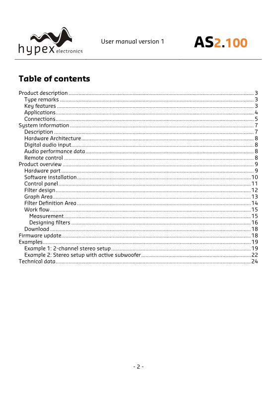
Table of contents
Product description .................................................................................................................................. 3
Type remarks ........................................................................................................................................ 3
Key features .......................................................................................................................................... 3
Applications........................................................................................................................................... 4
Connections........................................................................................................................................... 5
System information ................................................................................................................................. 7
Description ............................................................................................................................................ 7
Hardware Architecture......................................................................................................................... 8
Digital audio input................................................................................................................................ 8
Audio performance data...................................................................................................................... 8
Remote control ..................................................................................................................................... 8
Product overview ...................................................................................................................................... 9
Hardware part ....................................................................................................................................... 9
Software installation..........................................................................................................................10
Control panel.......................................................................................................................................11
Filter design.........................................................................................................................................12
Graph Area...........................................................................................................................................13
Filter Definition Area ..........................................................................................................................14
Work flow.............................................................................................................................................15
Measurement...................................................................................................................................15
Designing filters ..............................................................................................................................16
Download.............................................................................................................................................18
Firmware update.....................................................................................................................................18
Examples..................................................................................................................................................19
Example 1: 2-channel stereo setup..................................................................................................19
Example 2: Stereo setup with active subwoofer.............................................................................22
Technical data.........................................................................................................................................24
User manual version 1 AS2.100
- 3 -
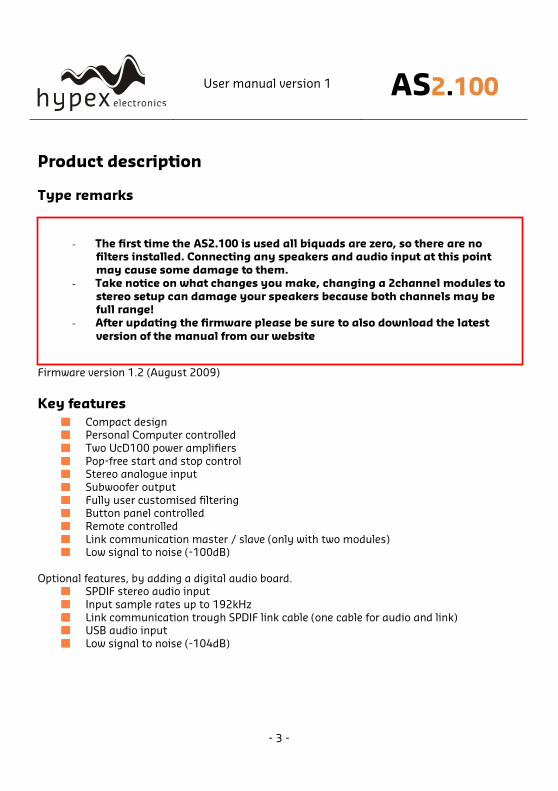
Product description
Type remarks
Firmware version 1.2 (August 2009)
Key features
Compact design Personal Computer controlled
Two UcD100 power amplifiers
Pop-free start and stop control Stereo analogue input
Subwoofer output
Fully user customised filtering Button panel controlled
Remote controlled
Link communication master / slave (only with two modules) Low signal to noise (-100dB)
Optional features, by adding a digital audio board. SPDIF stereo audio input
Input sample rates up to 192kHz
Link communication trough SPDIF link cable (one cable for audio and link) USB audio input
Low signal to noise (-104dB)
- The first time the AS2.100 is used all biquads are zero, so there are no
filters installed. Connecting any speakers and audio input at this point
may cause some damage to them.
- Take notice on what changes you make, changing a 2channel modules to
stereo setup can damage your speakers because both channels may be
full range!
- After updating the firmware please be sure to also download the latest
version of the manual from our website
User manual version 1 AS2.100
- 4 -
Applications
With one module the following applications can be set up, further explained in the “Hardware
part” chapter : Stereo passive filtered system
Briged mode for single subwoofer (max 140Watt into 4 Ohms)
Mono/mid 2-way setup (tweeter + sub)
When two modules are used the following applications can be set up, also explained in
“Hardware part”: 2-way active filtered stereo system
2 channel system with active subwoofer
2 channel system, both modules in bridge mode for more power
All setups are both possible with analogue and optional with the digital audio inputs SPDIF and
USB.
Note that all setups have the ability to use an extra channel by connecting a active subwoofer
to the subout. By this you will have the opportunity to build a 3-way system.
User manual version 1 AS2.100
- 5 -
Connections
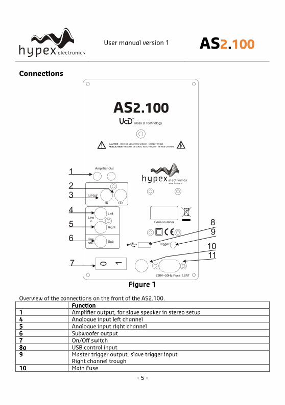
Figure Figure Figure Figure 1111
Overview of the connections on the front of the AS2.100.
FunctionFunctionFunctionFunction
1111 Amplifier output, for slave speaker in stereo setup
4444 Analogue input left channel
5555 Analogue input right channel
6666 Subwoofer output
7777 On/Off switch
8a8a8a8a USB control input
9999 Master trigger output, slave trigger input
Right channel trough
10101010 Main Fuse
User manual version 1 AS2.100
- 6 -
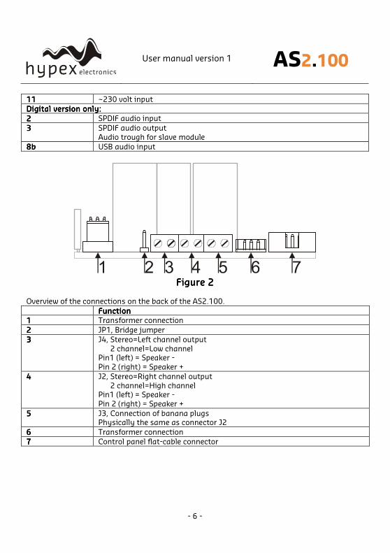
11111111 ~230 volt input
Digital version only:Digital version only:Digital version only:Digital version only:
2222 SPDIF audio input
3333 SPDIF audio output
Audio trough for slave module
8b8b8b8b USB audio input
Figure Figure Figure Figure 2222
Overview of the connections on the back of the AS2.100.
FunctionFunctionFunctionFunction
1111 Transformer connection
2222 JP1, Bridge jumper
3333 J4, Stereo=Left channel output
2 channel=Low channel Pin1 (left) = Speaker -
Pin 2 (right) = Speaker +
4444 J2, Stereo=Right channel output
2 channel=High channel Pin1 (left) = Speaker -
Pin 2 (right) = Speaker +
5555 J3, Connection of banana plugs Physically the same as connector J2
6666 Transformer connection
7777 Control panel flat-cable connector
User manual version 1 AS2.100
- 7 -
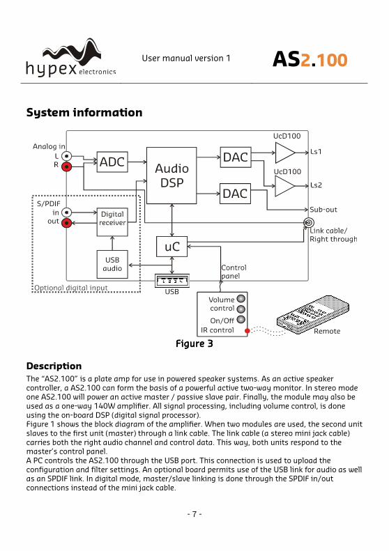
System information
Figure Figure Figure Figure 3333
Description
The “AS2.100” is a plate amp for use in powered speaker systems. As an active speaker
controller, a AS2.100 can form the basis of a powerful active two-way monitor. In stereo mode one AS2.100 will power an active master / passive slave pair. Finally, the module may also be
used as a one-way 140W amplifier. All signal processing, including volume control, is done
using the on-board DSP (digital signal processor). Figure 1 shows the block diagram of the amplifier. When two modules are used, the second unit
slaves to the first unit (master) through a link cable. The link cable (a stereo mini jack cable)
carries both the right audio channel and control data. This way, both units respond to the master’s control panel.
A PC controls the AS2.100 through the USB port. This connection is used to upload the
configuration and filter settings. An optional board permits use of the USB link for audio as well as an SPDIF link. In digital mode, master/slave linking is done through the SPDIF in/out
connections instead of the mini jack cable.
User manual version 1 AS2.100
- 8 -
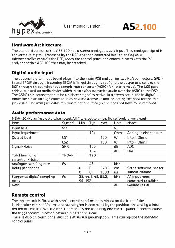
Hardware Architecture
The standard version of the AS2.100 has a stereo analogue audio input. This analogue signal is
converted to digital, processed by the DSP and then converted back to analogue. A microcontroller controls the DSP, reads the control panel and communicates with the PC
and/or another AS2.100 that may be attached.
Digital audio input
The optional digital input board plugs into the main PCB and carries two RCA connectors, SPDIF
in and SPDIF through. Incoming SPDIF is linked through directly to the output and sent to the DSP through an asynchronous sample rate converter (ASRC) for jitter removal. The USB part
adds a hub and an audio device which in turn also transmits audio over the ASRC to the DSP.
The ASRC chip scans its input for whichever signal is active. In a stereo setup and in digital mode the SPDIF through cable doubles as a master/slave link, obviating the need for the mini
jack cable. The mini jack cable remains functional though and does not have to be removed.
Audio performance data
MBW=20kHz, unless otherwise noted. All filters set to unity. Noise levels unweighted.
Item Symbol Min Typ Max Unit Notes
Input level Vin 2.2 V
Input impedance 10k Ohm Analogue cinch inputs
LS1 100 W Into 4 Ohms Output level
LS2 100 W Into 4 Ohms
100 dB ADC Signal/Noise SNR
104 dB DAC
Total harmonic
distortion+Noise
THD+N TBD
Analogue sampling rate Fs 48 kHz
0 0 340,3 cm Delay per channel
0 0 1000 us
Set in software, not for subout channel
Supported digital sampling
rates
Fs 32, 44.1, 48, 88.2,
96, 192
kHz All input rates
converted to 48kHz
Gain 20 dB volume at 0dB
Remote control
The master unit is fitted with small control panel which is placed on the front of the
loudspeaker cabinet. Volume and standby/on is controlled by the pushbuttons and by a infra red remote control. When 2 AS2.100 modules are used only oneoneoneone control panel is needed, cause
the trigger communication between master and slave.
There is also an touch panel available at www.hypexshop.com. This can replace the standard control panel.
User manual version 1 AS2.100
- 9 -
Stereo audio in
Right speaker
Left speaker
PC amp V1.0
Led
Volume Down
Volume Up
Ir Reciever
On/OffControl Panel
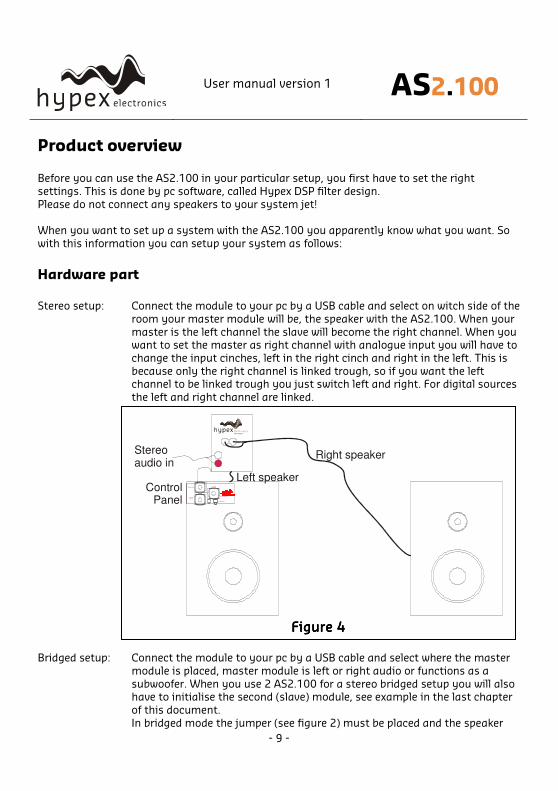
Figure Figure Figure Figure 4444
Product overview Before you can use the AS2.100 in your particular setup, you first have to set the right
settings. This is done by pc software, called Hypex DSP filter design.
Please do not connect any speakers to your system jet!
When you want to set up a system with the AS2.100 you apparently know what you want. So
with this information you can setup your system as follows:
Hardware part
Stereo setup: Connect the module to your pc by a USB cable and select on witch side of the
room your master module will be, the speaker with the AS2.100. When your
master is the left channel the slave will become the right channel. When you want to set the master as right channel with analogue input you will have to
change the input cinches, left in the right cinch and right in the left. This is
because only the right channel is linked trough, so if you want the left channel to be linked trough you just switch left and right. For digital sources
the left and right channel are linked.
Bridged setup: Connect the module to your pc by a USB cable and select where the master
module is placed, master module is left or right audio or functions as a
subwoofer. When you use 2 AS2.100 for a stereo bridged setup you will also have to initialise the second (slave) module, see example in the last chapter
of this document.
In bridged mode the jumper (see figure 2) must be placed and the speaker
User manual version 1 AS2.100
- 10 -
must be connected between J4 speaker+ and J2 speaker+. In all other setups the jumper is not placed!
When you want to set the master as right channel with analogue input you
will have to change the input cinches, left in the right cinch and right in the left. This is because only the right channel is linked trough, so if you want
the left channel to be linked trough you just switch left and right. For digital
sources the left and right channel are linked.
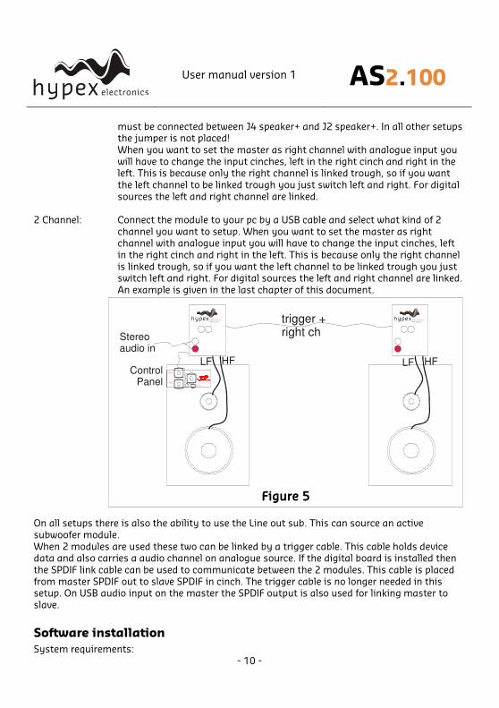
2 Channel: Connect the module to your pc by a USB cable and select what kind of 2
channel you want to setup. When you want to set the master as right channel with analogue input you will have to change the input cinches, left
in the right cinch and right in the left. This is because only the right channel
is linked trough, so if you want the left channel to be linked trough you just switch left and right. For digital sources the left and right channel are linked.
An example is given in the last chapter of this document.
On all setups there is also the ability to use the Line out sub. This can source an active
subwoofer module.
When 2 modules are used these two can be linked by a trigger cable. This cable holds device data and also carries a audio channel on analogue source. If the digital board is installed then
the SPDIF link cable can be used to communicate between the 2 modules. This cable is placed
from master SPDIF out to slave SPDIF in cinch. The trigger cable is no longer needed in this setup. On USB audio input on the master the SPDIF output is also used for linking master to
slave.
Software installation
System requirements:
PC amp V1.0
Led
Volume Down
Volume Up
Ir Reciever
On/Off
Stereo audio in
Control Panel
trigger +right ch
LF HF LF HF
Figure Figure Figure Figure 5555
User manual version 1 AS2.100
- 11 -
• Pentium class or higher • 64MB RAM
• USB1.0 or higher
Tested on Windows XP and Vista
All files are compressed in the setup.zip file. This zip file contains 2 DLL files for communication
and a .EXE file, which represents the Hypex DSP filter design program.
1. Unzip the setup.zip file on your hard disk
2. Open the “Hypex DSP filter design.EXE” by double clicking the file
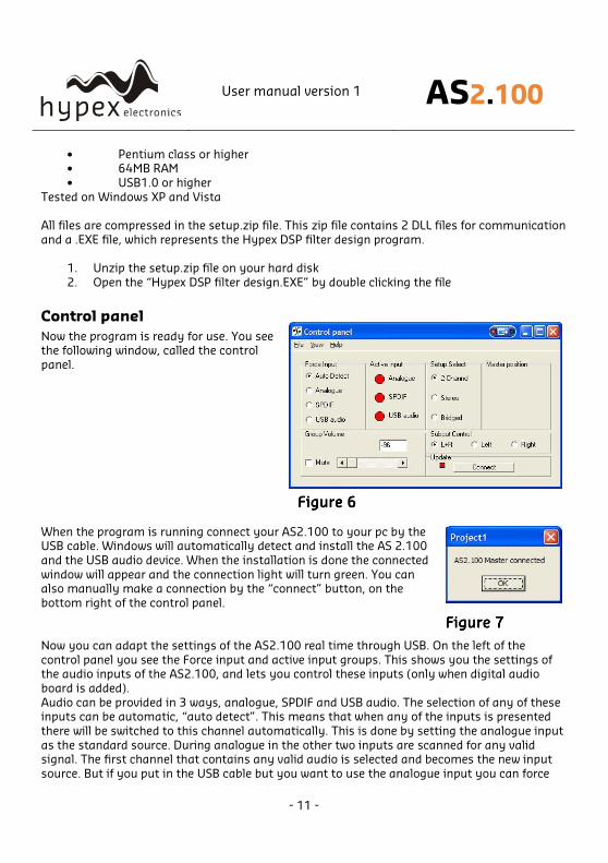
Control panel
Now the program is ready for use. You see the following window, called the control
panel.
Figure Figure Figure Figure 6666
When the program is running connect your AS2.100 to your pc by the USB cable. Windows will automatically detect and install the AS 2.100
and the USB audio device. When the installation is done the connected
window will appear and the connection light will turn green. You can also manually make a connection by the “connect” button, on the
bottom right of the control panel.
Now you can adapt the settings of the AS2.100 real time through USB. On the left of the
control panel you see the Force input and active input groups. This shows you the settings of the audio inputs of the AS2.100, and lets you control these inputs (only when digital audio
board is added).
Audio can be provided in 3 ways, analogue, SPDIF and USB audio. The selection of any of these inputs can be automatic, “auto detect”. This means that when any of the inputs is presented
there will be switched to this channel automatically. This is done by setting the analogue input
as the standard source. During analogue in the other two inputs are scanned for any valid signal. The first channel that contains any valid audio is selected and becomes the new input
source. But if you put in the USB cable but you want to use the analogue input you can force
Figure Figure Figure Figure 7777
User manual version 1 AS2.100
- 12 -
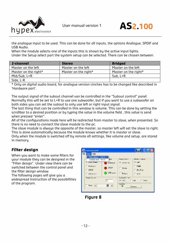
the analogue input to be used. This can be done for all inputs, the options Analogue, SPDIF and USB Audio.
When the module selects one of the inputs this is shown by the active input lights.
Under the Setup select part the system setup can be selected. There can be chosen between:
2-channel Stereo Bridged
Master on the left Master on the left Master on the left
Master on the right* Master on the right* Master on the right*
Mid/Sub, L+R Sub, L+R
Side, L-R
* Only on digital audio board, for analogue version cinches has to be changed like described in
‘Hardware part’.
The output signal of the subout channel van be controlled in the “Subout control” panel.
Normally this will be set to L+R to use one subwoofer, but if you want to use a subwoofer on
both sides you can set the subout to only use left or right input signal. The last thing that can be controlled in this window is volume. This can be done by setting the
scrollbar to a desired position or by typing the value in the volume field , this value is send
when pressed “enter”. All of the configurations made here will be redirected from master to slave, when presented. So
there is no need to connect the slave module to the pc.
The slave module is always the opposite of the master, so master left will set the slave to right. This is done automatically because the module knows whether it is master or slave.
Only when the module is switched off by remote all settings, like volume and setup, are stored
in memory.
Filter design
When you want to make some filters for your module they can be designed in the
“Filter design”. Under view there can be
switched between the control panel and the filter design window.
The following pages will give you a
widespread instruction of the possibilities of the program.
Figure Figure Figure Figure 8888
User manual version 1 AS2.100
- 13 -
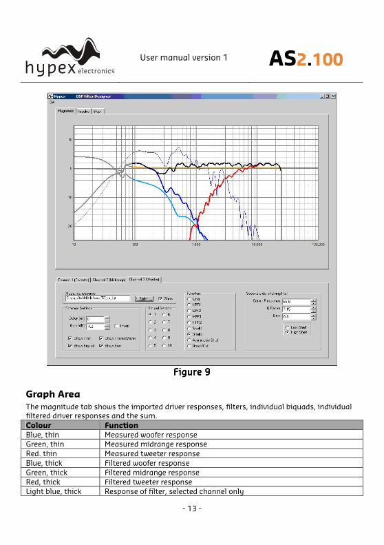
Figure Figure Figure Figure 9999
Graph Area
The magnitude tab shows the imported driver responses, filters, individual biquads, individual
filtered driver responses and the sum.
Colour Function
Blue, thin Measured woofer response
Green, thin Measured midrange response
Red. thin Measured tweeter response
Blue, thick Filtered woofer response
Green, thick Filtered midrange response
Red, thick Filtered tweeter response
Light blue, thick Response of filter, selected channel only
User manual version 1 AS2.100
- 14 -
Orange, thick Response of selected biquad
Black, thick Sum response
Having all of these on at the same time quickly produces an intractable mess so these graphs
can be separately enabled or disabled in the filter definition area.
The impulse or step tabs show the time domain response of the imported drivers and the sum response, and are used to demarcate the anechoic portion.
Filter Definition Area
The three channel tabs, labelled Tweeter, Woofer and Subwoofer are functionally identical. The
top left frame is used to import response files. The “select” button opens a file. The “show”
checkbox turns display of the measured graph on or off. The Common Settings box controls global gain (for each channel), delay, and the visibility of plots.
The amplified channels have up to 12 biquads, selected using the “Biquad Section” radio
buttons in the middle. The Subwoofer lineout has only 6 biquads sections, for only simple filter settings. To the right is a settings area specific to the type of function selected. Unused
biquads are set to unity.
The selected biquad is edited by selecting a function and setting relevant parameters. The delay has a maximum value of 1000us for channel 1 and 2. The subwoofer channel does
not include any delay. Distance is calculated by soundspeed/delay=distance, maximum
distance is therefore 340,29meters/0,001secondes=34,029cm. Note that the minimum step-size is 0,708cm cause the sample rate of 48000.
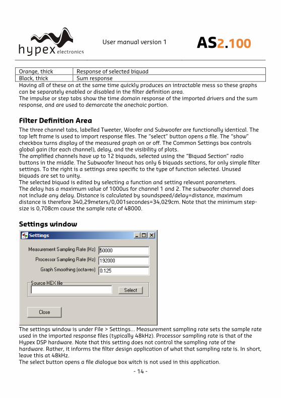
Settings window
The settings window is under File > Settings… Measurement sampling rate sets the sample rate used in the imported response files (typically 48kHz). Processor sampling rate is that of the
Hypex DSP hardware. Note that this setting does not control the sampling rate of the
hardware. Rather, it informs the filter design application of what that sampling rate is. In short, leave this at 48kHz.
The select button opens a file dialogue box witch is not used in this application.
User manual version 1 AS2.100
- 15 -
Work flow
Measurement
Measuring using the DSP unit set to “flat” Perform impulse response measurements for each driver separately. Save the entire impulse
record – truncation can be done later on the filter design program.
Measuring using an external amplifier A separate amplifier may also be used for measuring the drivers, provided the amplifier’s
output impedance is as low as the DSP unit’s.
Importing response data
Select the tab for the channel you want to import and click “select”. The filter designer expects the impulse response measurement as a text file with one sample per line.
There is no restriction on the absolute gain of the impulse response data. The only thing that
matters is that the absolute gain be the same for all three measurements. The filter designer computes a gain offset based on all loaded responses to centre them collectively on the vertical
scale.
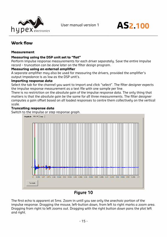
Truncating response data Switch to the impulse or step response graph.
Figure Figure Figure Figure 10101010 The first echo is apparent at 5ms. Zoom in until you see only the anechoic portion of the
impulse response. Dragging the mouse, left-button down, from left to right marks a zoom area.
Dragging from right to left zooms out. Dragging with the right button down pans the plot left and right.
User manual version 1 AS2.100
- 16 -
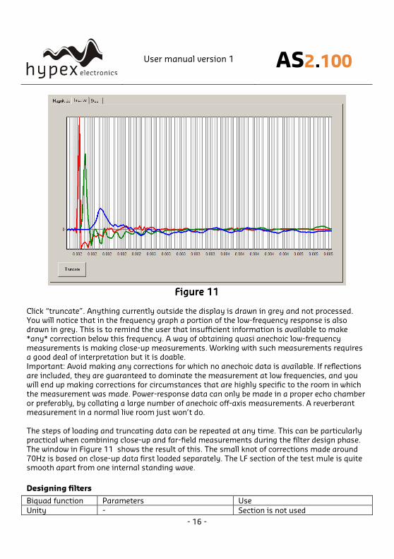
Figure Figure Figure Figure 11111111
Click “truncate”. Anything currently outside the display is drawn in grey and not processed.
You will notice that in the frequency graph a portion of the low-frequency response is also drawn in grey. This is to remind the user that insufficient information is available to make
*any* correction below this frequency. A way of obtaining quasi anechoic low-frequency
measurements is making close-up measurements. Working with such measurements requires a good deal of interpretation but it is doable.
Important: Avoid making any corrections for which no anechoic data is available. If reflections
are included, they are guaranteed to dominate the measurement at low frequencies, and you will end up making corrections for circumstances that are highly specific to the room in which
the measurement was made. Power-response data can only be made in a proper echo chamber
or preferably, by collating a large number of anechoic off-axis measurements. A reverberant measurement in a normal live room just won’t do.
The steps of loading and truncating data can be repeated at any time. This can be particularly practical when combining close-up and far-field measurements during the filter design phase.
The window in Figure 11 shows the result of this. The small knot of corrections made around
70Hz is based on close-up data first loaded separately. The LF section of the test mule is quite smooth apart from one internal standing wave.
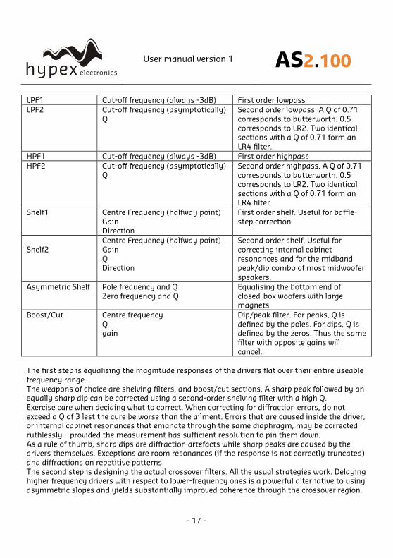
Designing filters
Biquad function Parameters Use
Unity - Section is not used
User manual version 1 AS2.100
- 17 -
LPF1 Cut-off frequency (always -3dB) First order lowpass
LPF2 Cut-off frequency (asymptotically)
Q
Second order lowpass. A Q of 0.71
corresponds to butterworth. 0.5
corresponds to LR2. Two identical sections with a Q of 0.71 form an
LR4 filter.
HPF1 Cut-off frequency (always -3dB) First order highpass
HPF2 Cut-off frequency (asymptotically) Q
Second order highpass. A Q of 0.71 corresponds to butterworth. 0.5
corresponds to LR2. Two identical
sections with a Q of 0.71 form an LR4 filter.
Shelf1 Centre Frequency (halfway point)
Gain
Direction
First order shelf. Useful for baffle-
step correction
Shelf2
Centre Frequency (halfway point)
Gain
Q Direction
Second order shelf. Useful for
correcting internal cabinet
resonances and for the midband peak/dip combo of most midwoofer
speakers.
Asymmetric Shelf Pole frequency and Q
Zero frequency and Q
Equalising the bottom end of
closed-box woofers with large magnets
Boost/Cut Centre frequency
Q gain
Dip/peak filter. For peaks, Q is
defined by the poles. For dips, Q is defined by the zeros. Thus the same
filter with opposite gains will
cancel.
The first step is equalising the magnitude responses of the drivers flat over their entire useable
frequency range.
The weapons of choice are shelving filters, and boost/cut sections. A sharp peak followed by an equally sharp dip can be corrected using a second-order shelving filter with a high Q.
Exercise care when deciding what to correct. When correcting for diffraction errors, do not
exceed a Q of 3 lest the cure be worse than the ailment. Errors that are caused inside the driver, or internal cabinet resonances that emanate through the same diaphragm, may be corrected
ruthlessly – provided the measurement has sufficient resolution to pin them down.
As a rule of thumb, sharp dips are diffraction artefacts while sharp peaks are caused by the drivers themselves. Exceptions are room resonances (if the response is not correctly truncated)
and diffractions on repetitive patterns.
The second step is designing the actual crossover filters. All the usual strategies work. Delaying higher frequency drivers with respect to lower-frequency ones is a powerful alternative to using
asymmetric slopes and yields substantially improved coherence through the crossover region.
User manual version 1 AS2.100
- 18 -
Download
Under download the user can press “load DSP” to download its designed filters to the AS2.100.
Firmware update Every module has the ability to update its firmware, when Hypex provides a new firmware version. The firmware version of the module is shown in the statusbar of the filter design
window and under About.
The firmware can be easily updated by USB, the same for master and slave module. Under option “download” you can find “Firmware update”. When this option is selected the user can
select the new firmware file. This is a complete hex file provided by Hypex, no adapts can and
may be made by the user! After the file is selected the update begins.
DO NOT DISCONNECT THE MODULE AT THIS PIONT!
When the progress bar is filled the update is completed. On a CRC error the update is automatically restarted, after three errors the update is aborted.
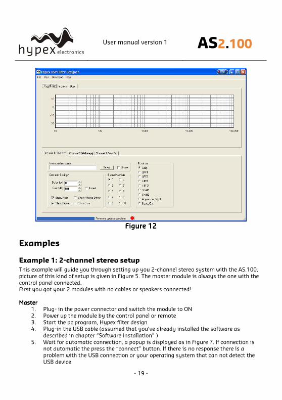
Figure 12 shows a completed firmware update.
After restarting the module the new firmware is running.
NoteNoteNoteNote that the new firmware does not have any filters installed, so the filters must be reloaded with the
correct values.
User manual version 1 AS2.100
- 19 -
Figure Figure Figure Figure 12121212
Examples
Example 1: 2-channel stereo setup
This example will guide you through setting up you 2-channel stereo system with the AS.100,
picture of this kind of setup is given in Figure 5. The master module is always the one with the
control panel connected. First you got your 2 modules with no cables or speakers connected!.
MasterMasterMasterMaster 1. Plug- in the power connector and switch the module to ON
2. Power up the module by the control panel or remote
3. Start the pc program, Hypex filter design 4. Plug-in the USB cable (assumed that you’ve already installed the software as
described in chapter “Software installation” )
5. Wait for automatic connection, a popup is displayed as in Figure 7. If connection is not automatic the press the “connect” button. If there is no response there is a
problem with the USB connection or your operating system that can not detect the
USB device
User manual version 1 AS2.100
- 20 -
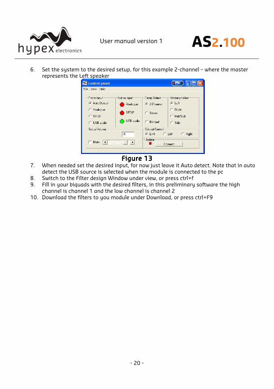
6. Set the system to the desired setup, for this example 2-channel – where the master represents the Left speaker
Figure Figure Figure Figure 13131313 7. When needed set the desired input, for now just leave it Auto detect. Note that in auto
detect the USB source is selected when the module is connected to the pc 8. Switch to the Filter design Window under view, or press ctrl+f
9. Fill in your biquads with the desired filters, in this preliminary software the high
channel is channel 1 and the low channel is channel 2 10. Download the filters to you module under Download, or press ctrl+F9
User manual version 1 AS2.100
- 21 -
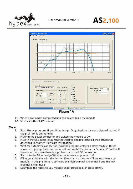
Figure Figure Figure Figure 14141414
11. When download is completed you can power down the module
12. Start with the SLAVE module
SlaveSlaveSlaveSlave
1. Start the pc program, Hypex filter design. Or go back to the control panel (ctrl+c) if
the program is still running 2. Plug- in the power connector and switch the module to ON
3. Plug-in the USB cable (assumed that you’ve already installed the software as
described in chapter “Software installation” ) 4. Wait for automatic connection, now the program detects a slave module, this is
shown in a popup. If connection is not automatic the press the “connect” button. If
there is no response there is a problem with the USB connection 5. Switch to the Filter design Window under view, or press ctrl+f
6. Fill in your biquads with the desired filters or use the same filters as the master
module. In this preliminary software the high channel is channel 1 and the low channel is channel 2
7. Download the filters to you module under Download, or press ctrl+F9
User manual version 1 AS2.100
- 22 -
8. When download is completed you can power down the module and disconnect the USB cable
9. Master and Slave are now set up as a 2 channel stereo system
Final setupFinal setupFinal setupFinal setup
When both modules are installed it is time to complete your setup.
- First connect your speakers as explained in chapter Product overview - Connect the trigger cable (mini jack) orororor SPDIF cable between both modules, depending
on the used audio source
- Power up master and slave module - Turn on the master by control panel or remote
- Lower you source volume, prevent loud start-up volume
- Connect your source to the AS2.100 Ready!
Now the system is fully setup and can be controlled by the control panel, remote control or by connecting the module to your pc. From now on you can update your filters at any time, just
repeat the Master and Slave steps.
* If your slave module is not turned on by the master try to power down the slave, turn the
master off, wait 5 seconds, power up slave and turn the master back on * When there is something that does not work try to repeat the installation
Example 2: Stereo setup with active subwoofer
This example describes how to set up a stereo passive filtered audio system plus an active
subwoofer (with or without filtering) with use of one AS2.100. This setup is shown in Figure 4.
At first you have only a AS2.100 with no cables connected. 1. Plug- in the power connector and switch the module to ON
2. Power up the module by the control panel or remote
3. Start the pc program, Hypex filter design 4. Plug-in the USB cable (assumed that you’ve already installed the software as
described in chapter “Software installation” )
5. Wait for automatic connection, a popup is displayed as in Figure 7. If connection is not automatic the press the “connect” button. If there is no response there is a
problem with the USB connection or your operating system that can not detect the
USB device
User manual version 1 AS2.100
- 23 -
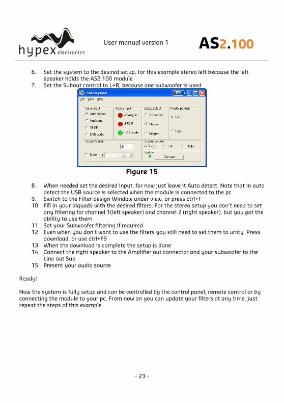
6. Set the system to the desired setup, for this example stereo left because the left speaker holds the AS2.100 module
7. Set the Subout control to L+R, because one subwoofer is used
Figure Figure Figure Figure 15151515
8. When needed set the desired input, for now just leave it Auto detect. Note that in auto
detect the USB source is selected when the module is connected to the pc 9. Switch to the Filter design Window under view, or press ctrl+f
10. Fill in your biquads with the desired filters. For the stereo setup you don’t need to set
any filtering for channel 1(left speaker) and channel 2 (right speaker), but you got the ability to use them
11. Set your Subwoofer filtering if required
12. Even when you don’t want to use the filters you still need to set them to unity. Press download, or use ctrl+F9
13. When the download is complete the setup is done
14. Connect the right speaker to the Amplifier out connector and your subwoofer to the Line out Sub
15. Present your audio source
Ready!
Now the system is fully setup and can be controlled by the control panel, remote control or by connecting the module to your pc. From now on you can update your filters at any time, just
repeat the steps of this example.

User manual version 1 AS2.100
- 24 -
Technical data Supply voltage 230Volt AC/50Hz +/-10% Dimensions 115mmx200mmx60mm (WxHxD)
Plate thickness 2,5mm
Weight 1,5 kg Clearance 9mm
Warranty The work carries warranty out for all provable material and production defects for the duration of 12 months starting from sales. All damage, which is caused by wrong or inappropriate
operation, is excluded from the warranty.