Embed Size (px)
Citation preview
User Manual V1.1
User Manual -Installation -Operation
Z10I1K Z10I1K5 Z10I2K Z10I2K5 Z10I3K
Zeus Appollo Solar

Catalogue
1. Notes on this manual ......................................................................................................................................................... 2
1.1 Scope of Validation ...................................................................................................................................................... 2
1.2 Symbols Used ............................................................................................................................................................. 2
1.3 Target Group ............................................................................................................................................................... 3
2. Preparation ........................................................................................................................................................................ 4
2.1 Safety Instructions ....................................................................................................................................................... 4
2.2 Explanations of Symbols on Inverter ........................................................................................................................... 6
3. Product Information ............................................................................................................................................................ 7
3.1 Overview ...................................................................................................................................................................... 7
3.2 Major Characteristics ................................................................................................................................................... 8
3.3 Datasheet .................................................................................................................................................................... 9
4. Packing checklist ............................................................................................................................................................. 13
4.1 Assembly parts .......................................................................................................................................................... 13
4.2 Product Appearance .................................................................................................................................................. 14
4.3 Product Identification ................................................................................................................................................. 15
4.4 Further Information .................................................................................................................................................... 15
5. Installation ........................................................................................................................................................................ 15
5.1 Safety ........................................................................................................................................................................ 16
5.2 Mounting Instructions................................................................................................................................................. 17
5.3 Safety Clearance ....................................................................................................................................................... 18
5.4 Mounting Procedure .................................................................................................................................................. 19
5.5 Safety lock ................................................................................................................................................................. 22
6. Electrical Connection ....................................................................................................................................................... 24
6.1 Safety ........................................................................................................................................................................ 24
6.2 AC Side Connection .................................................................................................................................................. 24
6.3 DC Side Connection .................................................................................................................................................. 27
6.4 Communication and Monitoring Device ..................................................................................................................... 32
7. Display and Operation ..................................................................................................................................................... 33
7.1 LCD Panel ................................................................................................................................................................. 33
7.2 Commissioning .......................................................................................................................................................... 35
7.3 Operation ................................................................................................................................................................... 35
7.4 State Information ....................................................................................................................................................... 47
8. Troubleshooting .............................................................................................................................................................. 48
9. Abbreviation ..................................................................................................................................................................... 50
10. Contact............................................................................................................................................................................. 51
2
1. Notes on this manual
1.1 Scope of Validation
The main purpose of this User Manual is to provide instructions and detailed procedures
for installing, operating, maintaining, and troubleshooting the following five types of Z10
series inverters:
Z10I1K
Z10I1K5
Z10I2K
Z10I2K5
Z10I3K
Please keep this user manual available at all times in case of emergency.
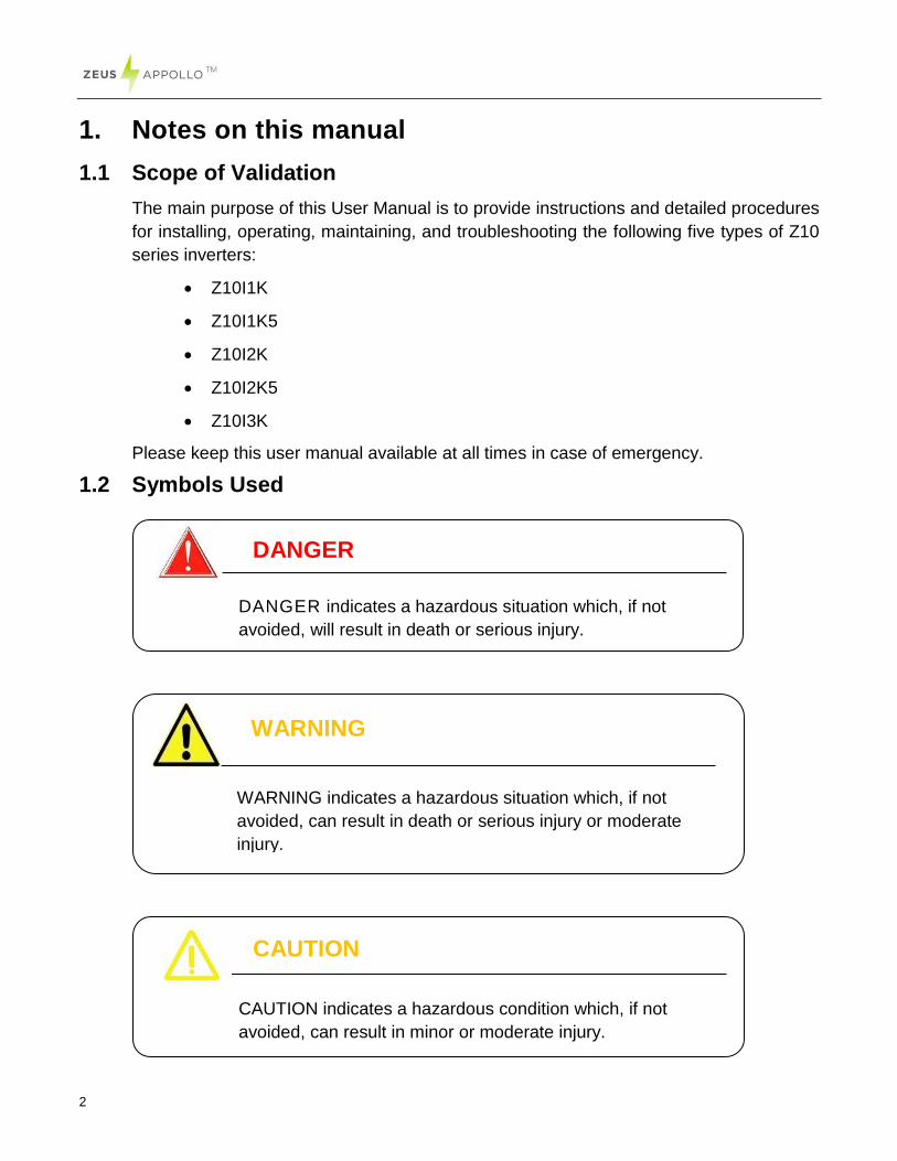
1.2 Symbols Used
CAUTION
CAUTION indicates a hazardous condition which, if not
avoided, can result in minor or moderate injury.
WARNING
WARNING indicates a hazardous situation which, if not
avoided, can result in death or serious injury or moderate
injury.
DANGER
DANGER indicates a hazardous situation which, if not
avoided, will result in death or serious injury.
3
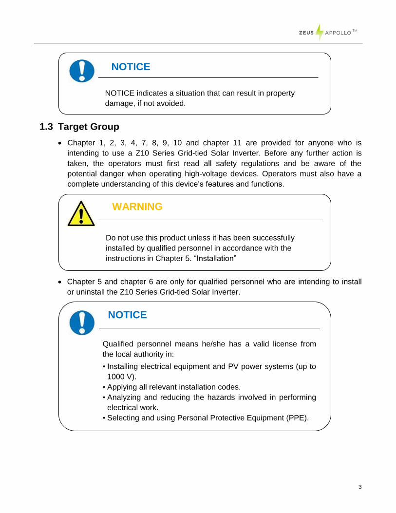
1.3 Target Group
Chapter 1, 2, 3, 4, 7, 8, 9, 10 and chapter 11 are provided for anyone who is
intending to use a Z10 Series Grid-tied Solar Inverter. Before any further action is
taken, the operators must first read all safety regulations and be aware of the
potential danger when operating high-voltage devices. Operators must also have a
complete understanding of this device’s features and functions.
Chapter 5 and chapter 6 are only for qualified personnel who are intending to install
or uninstall the Z10 Series Grid-tied Solar Inverter.
NOTICE
Qualified personnel means he/she has a valid license from
the local authority in:
• Installing electrical equipment and PV power systems (up to
1000 V).
• Applying all relevant installation codes.
• Analyzing and reducing the hazards involved in performing
electrical work.
• Selecting and using Personal Protective Equipment (PPE).
WARNING
Do not use this product unless it has been successfully
installed by qualified personnel in accordance with the
instructions in Chapter 5. “Installation”
NOTICE
NOTICE indicates a situation that can result in property
damage, if not avoided.
4
2. Preparation
2.1 Safety Instructions
WARNING
The installation, recycling and disposal of the inverters must
be performed by qualified personnel who must comply with
national and local standards and regulations. Please contact
your dealer to obtain details about an authorized repair
facility if the inverter requires maintenance or repair. Any
unauthorized activities including the modification of product
functionality of any kind will affect the extent of the warranty;
such actions may result in Zeus Appollo Solar not accepting
any responsibility or that warranty.
DANGER
DANGER due to electrical shock and high voltage
DO NOT touch the operating component of the inverter, it
might result in burning or death.
TO prevent risk of electric shock during installation and
maintenance, please make sure that all AC and DC
terminals are unplugged.
DO NOT remain close to the equipment while there are
severe weather conditions including storms, lightning etc.
5
CAUTION
The PV inverter will become hot during operation; please
don’t touch the heat sink or adjacent surface during or
shortly after operation.
Risk of damage due to modifications. Never modify or
manipulate the inverter or other components of the system.
NOTICE
Public utility only
The PV inverter is designed to feed AC power directly into
the public utility power grid; do not connect the AC output of
the device to any private AC equipment.
6
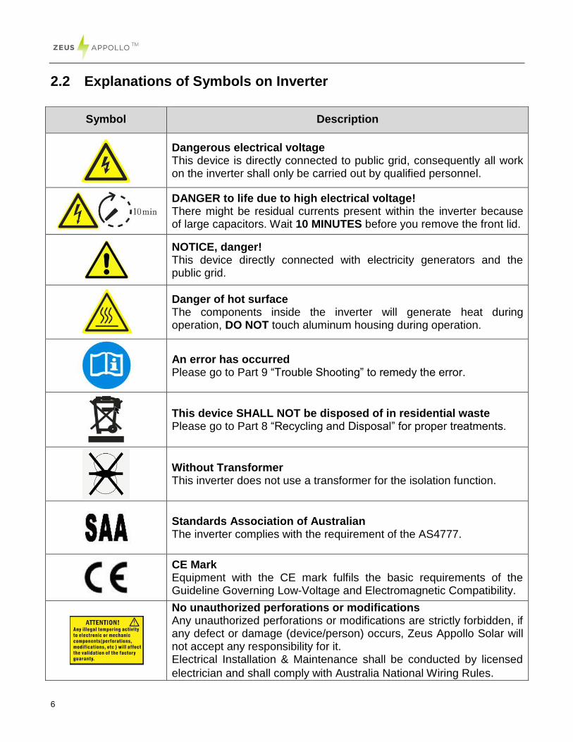
2.2 Explanations of Symbols on Inverter
Symbol Description
Dangerous electrical voltage This device is directly connected to public grid, consequently all work on the inverter shall only be carried out by qualified personnel.
DANGER to life due to high electrical voltage! There might be residual currents present within the inverter because of large capacitors. Wait 10 MINUTES before you remove the front lid.
NOTICE, danger! This device directly connected with electricity generators and the public grid.
Danger of hot surface The components inside the inverter will generate heat during operation, DO NOT touch aluminum housing during operation.
An error has occurred Please go to Part 9 “Trouble Shooting” to remedy the error.
This device SHALL NOT be disposed of in residential waste Please go to Part 8 “Recycling and Disposal” for proper treatments.
Without Transformer This inverter does not use a transformer for the isolation function.
Standards Association of Australian The inverter complies with the requirement of the AS4777.
CE Mark Equipment with the CE mark fulfils the basic requirements of the Guideline Governing Low-Voltage and Electromagnetic Compatibility.
No unauthorized perforations or modifications Any unauthorized perforations or modifications are strictly forbidden, if any defect or damage (device/person) occurs, Zeus Appollo Solar will not accept any responsibility for it. Electrical Installation & Maintenance shall be conducted by licensed
electrician and shall comply with Australia National Wiring Rules.
7
3. Product Information
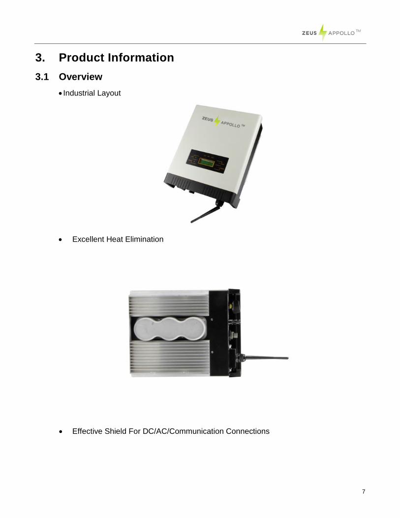
3.1 Overview
Industrial Layout
Excellent Heat Elimination
Effective Shield For DC/AC/Communication Connections
8
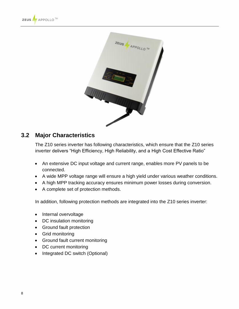
3.2 Major Characteristics
The Z10 series inverter has following characteristics, which ensure that the Z10 series
inverter delivers “High Efficiency, High Reliability, and a High Cost Effective Ratio”
An extensive DC input voltage and current range, enables more PV panels to be
connected.
A wide MPP voltage range will ensure a high yield under various weather conditions.
A high MPP tracking accuracy ensures minimum power losses during conversion.
A complete set of protection methods.
In addition, following protection methods are integrated into the Z10 series inverter:
Internal overvoltage
DC insulation monitoring
Ground fault protection
Grid monitoring
Ground fault current monitoring
DC current monitoring
Integrated DC switch (Optional)
9
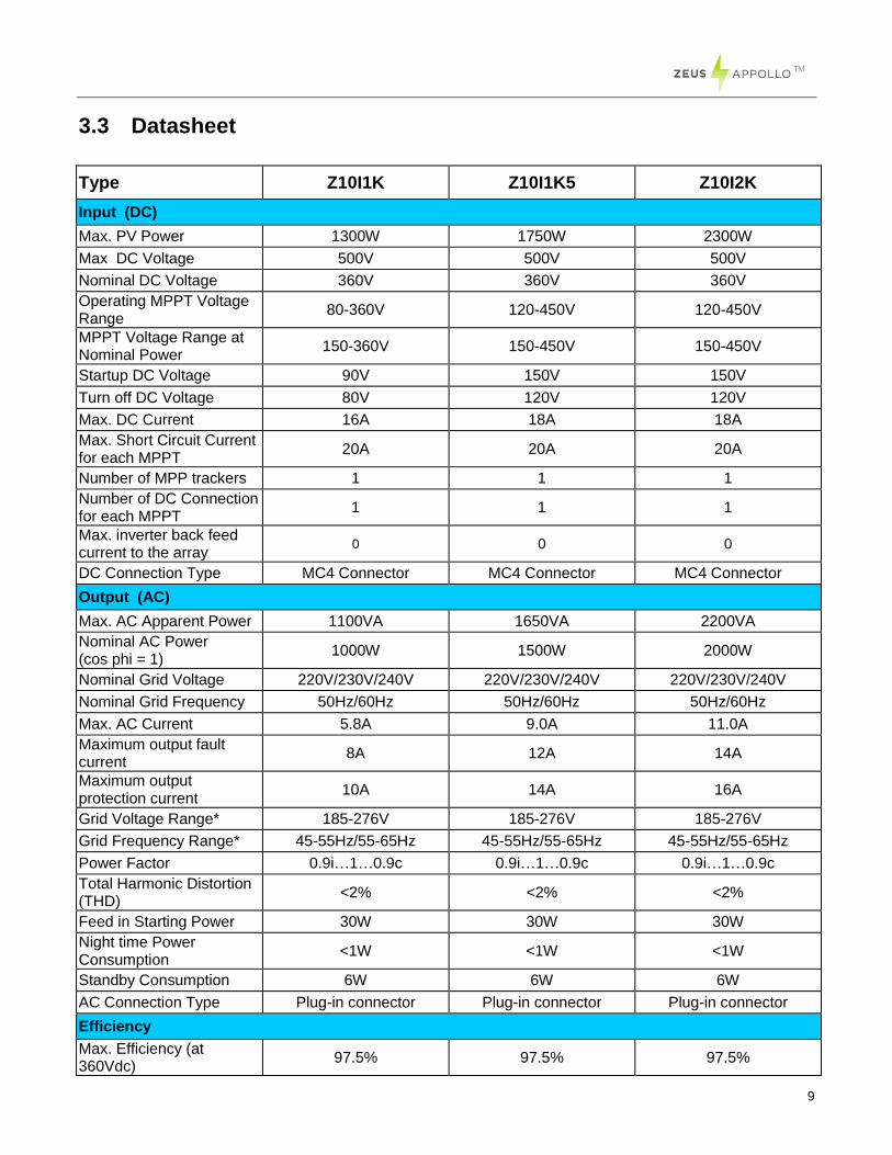
3.3 Datasheet
Type Z10I1K Z10I1K5 Z10I2K
Input (DC)
Max. PV Power 1300W 1750W 2300W
Max DC Voltage 500V 500V 500V
Nominal DC Voltage 360V 360V 360V
Operating MPPT Voltage Range
80-360V 120-450V 120-450V
MPPT Voltage Range at Nominal Power
150-360V 150-450V 150-450V
Startup DC Voltage 90V 150V 150V
Turn off DC Voltage 80V 120V 120V
Max. DC Current 16A 18A 18A
Max. Short Circuit Current for each MPPT
20A 20A 20A
Number of MPP trackers 1 1 1
Number of DC Connection for each MPPT
1 1 1
Max. inverter back feed current to the array
0 0 0
DC Connection Type MC4 Connector MC4 Connector MC4 Connector
Output (AC)
Max. AC Apparent Power 1100VA 1650VA 2200VA
Nominal AC Power (cos phi = 1)
1000W 1500W 2000W
Nominal Grid Voltage 220V/230V/240V 220V/230V/240V 220V/230V/240V
Nominal Grid Frequency 50Hz/60Hz 50Hz/60Hz 50Hz/60Hz
Max. AC Current 5.8A 9.0A 11.0A
Maximum output fault current
8A 12A 14A
Maximum output protection current
10A 14A 16A
Grid Voltage Range* 185-276V 185-276V 185-276V
Grid Frequency Range* 45-55Hz/55-65Hz 45-55Hz/55-65Hz 45-55Hz/55-65Hz
Power Factor 0.9i…1…0.9c 0.9i…1…0.9c 0.9i…1…0.9c
Total Harmonic Distortion (THD)
<2% <2% <2%
Feed in Starting Power 30W 30W 30W
Night time Power Consumption
<1W <1W <1W
Standby Consumption 6W 6W 6W
AC Connection Type Plug-in connector Plug-in connector Plug-in connector
Efficiency
Max. Efficiency (at 360Vdc)
97.5% 97.5% 97.5%
10
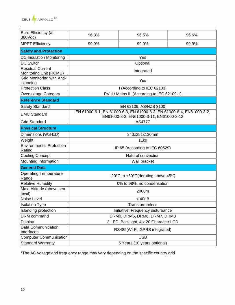
Euro Efficiency (at 360Vdc)
96.3% 96.5% 96.6%
MPPT Efficiency 99.9% 99.9% 99.9%
Safety and Protection
DC Insulation Monitoring Yes
DC Switch Optional
Residual Current Monitoring Unit (RCMU)
Integrated
Grid Monitoring with Anti-islanding
Yes
Protection Class I (According to IEC 62103)
Overvoltage Category PV II / Mains III (According to IEC 62109-1)
Reference Standard
Safety Standard EN 62109, AS/NZS 3100
EMC Standard EN 61000-6-1, EN 61000-6-3, EN 61000-6-2, EN 61000-6-4, EN61000-3-2,
EN61000-3-3, EN61000-3-11, EN61000-3-12
Grid Standard AS4777
Physical Structure
Dimensions (WxHxD) 343x281x130mm
Weight 11kg
Environmental Protection Rating
IP 65 (According to IEC 60529)
Cooling Concept Natural convection
Mounting Information Wall bracket
General Data
Operating Temperature Range
-20°C to +60°C(derating above 45℃)
Relative Humidity 0% to 98%, no condensation
Max. Altitude (above sea level)
2000m
Noise Level < 40dB
Isolation Type Transformerless
Islanding protection Initiative, Frequency disturbance
DRM command DRM0, DRM5, DRM6, DRM7, DRM8
Display 3 LED, Backlight, 4 x 20 Character LCD
Data Communication Interfaces
RS485(Wi-Fi, GPRS integrated)
Computer Communication USB
Standard Warranty 5 Years (10 years optional)
*The AC voltage and frequency range may vary depending on the specific country grid
11
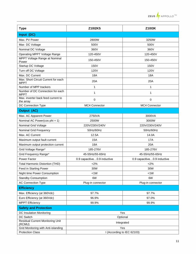
Type Z10I2K5 Z10I3K
Input (DC)
Max. PV Power 2800W 3250W
Max DC Voltage 500V 500V
Nominal DC Voltage 360V 360V
Operating MPPT Voltage Range 120-450V 120-450V
MPPT Voltage Range at Nominal Power
150-450V 150-450V
Startup DC Voltage 150V 150V
Turn off DC Voltage 120V 120V
Max. DC Current 18A 18A
Max. Short Circuit Current for each MPPT
20A 20A
Number of MPP trackers 1 1
Number of DC Connection for each MPPT
1 1
Max. inverter back feed current to the array
0 0
DC Connection Type MC4 Connector MC4 Connector
Output (AC)
Max. AC Apparent Power 2750VA 3000VA
Nominal AC Power(cos phi = 1) 2500W 3000W
Nominal Grid Voltage 220V/230V/240V 220V/230V/240V
Nominal Grid Frequency 50Hz/60Hz 50Hz/60Hz
Max. AC Current 12.5A 14.0A
Maximum output fault current 15A 17A
Maximum output protection current 18A 20A
Grid Voltage Range* 185-276V 185-276V
Grid Frequency Range* 45-55Hz/55-65Hz 45-55Hz/55-65Hz
Power Factor 0.9 capacitive…0.9 inductive 0.9 capacitive…0.9 inductive
Total Harmonic Distortion (THD) <2% <2%
Feed in Starting Power 30W 30W
Night time Power Consumption <1W <1W
Standby Consumption 6W 6W
AC Connection Type Plug-in connector Plug-in connector
Efficiency
Max. Efficiency (at 360Vdc) 97.7% 97.7%
Euro Efficiency (at 360Vdc) 96.9% 97.0%
MPPT Efficiency 99.9% 99.9%
Safety and Protection
DC Insulation Monitoring Yes
DC Switch Optional
Residual Current Monitoring Unit (RCMU)
Integrated
Grid Monitoring with Anti-islanding Yes
Protection Class I (According to IEC 62103)
12
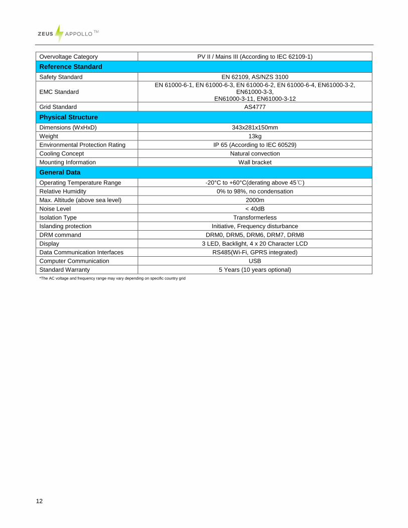
Overvoltage Category PV II / Mains III (According to IEC 62109-1)
Reference Standard
Safety Standard EN 62109, AS/NZS 3100
EMC Standard EN 61000-6-1, EN 61000-6-3, EN 61000-6-2, EN 61000-6-4, EN61000-3-2,
EN61000-3-3, EN61000-3-11, EN61000-3-12
Grid Standard AS4777
Physical Structure
Dimensions (WxHxD) 343x281x150mm
Weight 13kg
Environmental Protection Rating IP 65 (According to IEC 60529)
Cooling Concept Natural convection
Mounting Information Wall bracket
General Data
Operating Temperature Range -20°C to +60°C(derating above 45℃)
Relative Humidity 0% to 98%, no condensation
Max. Altitude (above sea level) 2000m
Noise Level < 40dB
Isolation Type Transformerless
Islanding protection Initiative, Frequency disturbance
DRM command DRM0, DRM5, DRM6, DRM7, DRM8
Display 3 LED, Backlight, 4 x 20 Character LCD
Data Communication Interfaces RS485(Wi-Fi, GPRS integrated)
Computer Communication USB
Standard Warranty 5 Years (10 years optional)
*The AC voltage and frequency range may vary depending on specific country grid
13
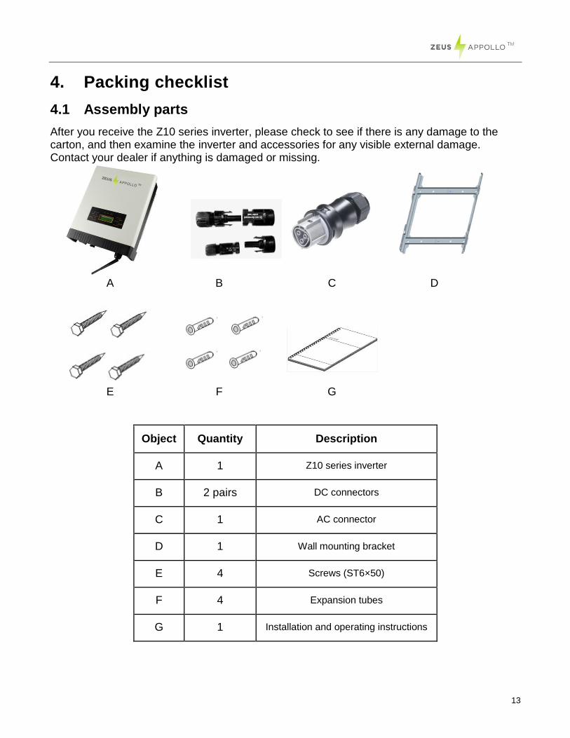
4. Packing checklist
4.1 Assembly parts
After you receive the Z10 series inverter, please check to see if there is any damage to the carton, and then examine the inverter and accessories for any visible external damage. Contact your dealer if anything is damaged or missing.
Object Quantity Description
A 1 Z10 series inverter
B 2 pairs DC connectors
C 1 AC connector
D 1 Wall mounting bracket
E 4 Screws (ST6×50)
F 4 Expansion tubes
G 1 Installation and operating instructions
A B C D
E F G
14
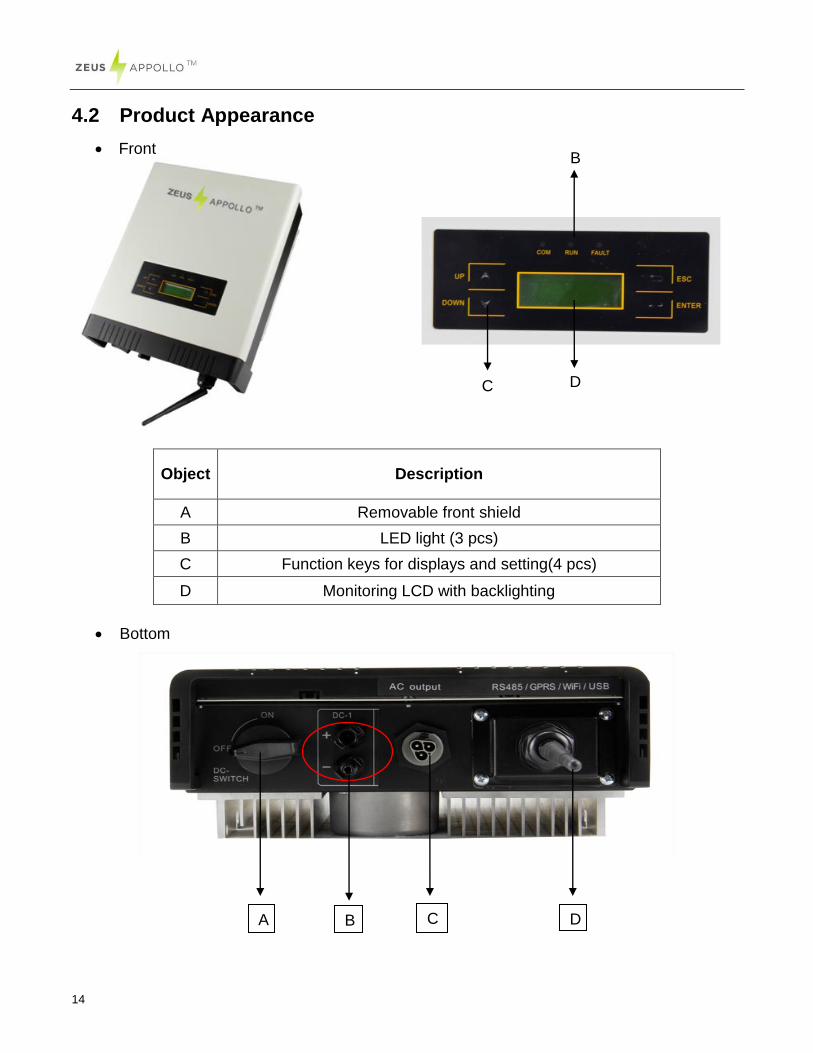
4.2 Product Appearance
Front
Object
Description
A Removable front shield
B LED light (3 pcs)
C Function keys for displays and setting(4 pcs)
D Monitoring LCD with backlighting
Bottom
A B C D
D
B
C
15
Object Description
A DC switch (optional)
B Plug connectors for DC input
C Terminal for grid connection (AC output)
D Communication interface(RS485/GPRS/Wi-Fi/USB)
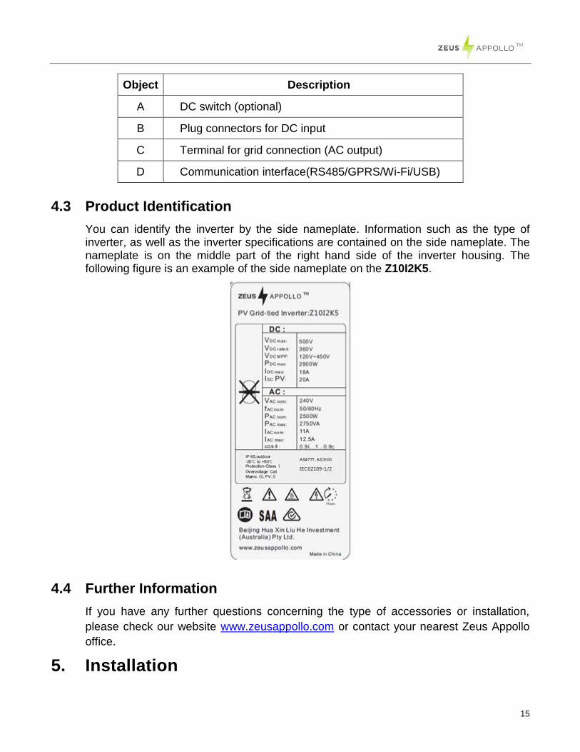
4.3 Product Identification
You can identify the inverter by the side nameplate. Information such as the type of inverter, as well as the inverter specifications are contained on the side nameplate. The nameplate is on the middle part of the right hand side of the inverter housing. The following figure is an example of the side nameplate on the Z10I2K5.
4.4 Further Information
If you have any further questions concerning the type of accessories or installation,
please check our website www.zeusappollo.com or contact your nearest Zeus Appollo
office.
5. Installation
16
5.1 Safety
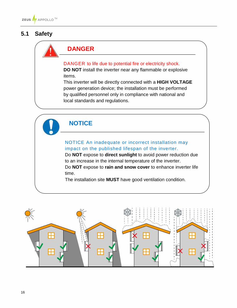
NOTICE
NOTICE An inadequate or incorrect installation may
impact on the published lifespan of the inverter.
Do NOT expose to direct sunlight to avoid power reduction due
to an increase in the internal temperature of the inverter.
Do NOT expose to rain and snow cover to enhance inverter life
time.
The installation site MUST have good ventilation condition.
DANGER
DANGER to life due to potential fire or electricity shock.
DO NOT install the inverter near any flammable or explosive
items.
This inverter will be directly connected with a HIGH VOLTAGE
power generation device; the installation must be performed
by qualified personnel only in compliance with national and
local standards and regulations.
17
5.2 Mounting Instructions
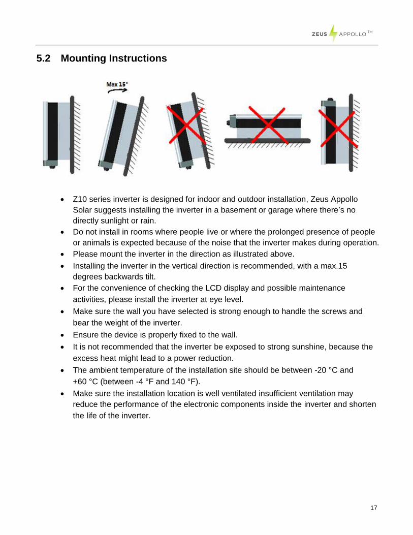
Z10 series inverter is designed for indoor and outdoor installation, Zeus Appollo
Solar suggests installing the inverter in a basement or garage where there’s no
directly sunlight or rain.
Do not install in rooms where people live or where the prolonged presence of people
or animals is expected because of the noise that the inverter makes during operation.
Please mount the inverter in the direction as illustrated above.
Installing the inverter in the vertical direction is recommended, with a max.15
degrees backwards tilt.
For the convenience of checking the LCD display and possible maintenance
activities, please install the inverter at eye level.
Make sure the wall you have selected is strong enough to handle the screws and
bear the weight of the inverter.
Ensure the device is properly fixed to the wall.
It is not recommended that the inverter be exposed to strong sunshine, because the
excess heat might lead to a power reduction.
The ambient temperature of the installation site should be between -20 °C and
+60 °C (between -4 °F and 140 °F).
Make sure the installation location is well ventilated insufficient ventilation may
reduce the performance of the electronic components inside the inverter and shorten
the life of the inverter.
18
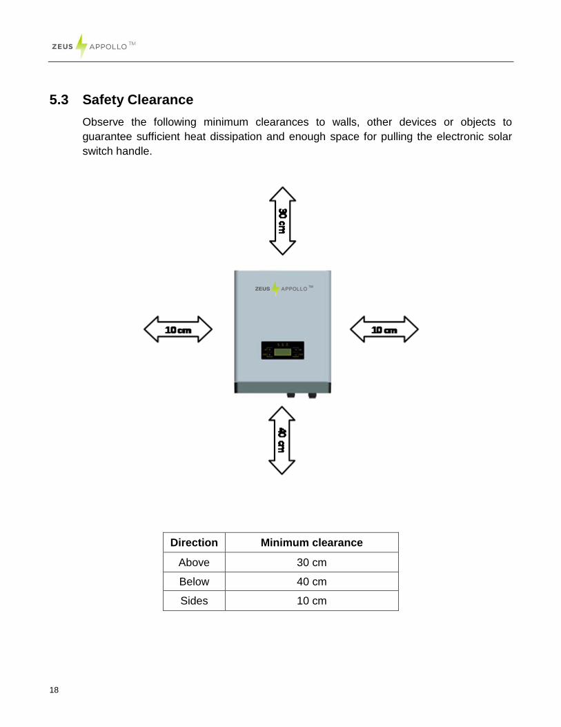
5.3 Safety Clearance
Observe the following minimum clearances to walls, other devices or objects to
guarantee sufficient heat dissipation and enough space for pulling the electronic solar
switch handle.
Direction Minimum clearance
Above 30 cm
Below 40 cm
Sides 10 cm
19
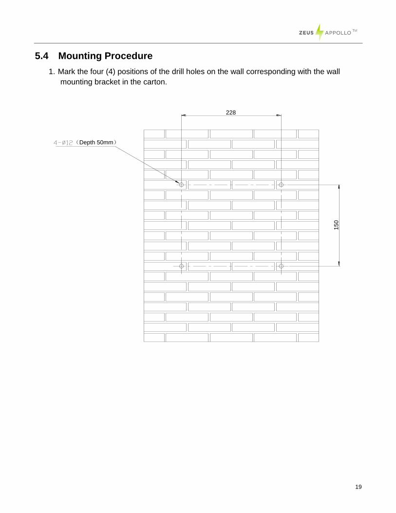
5.4 Mounting Procedure
1. Mark the four (4) positions of the drill holes on the wall corresponding with the wall
mounting bracket in the carton.
15
0
228
(Depth 50mm)
20
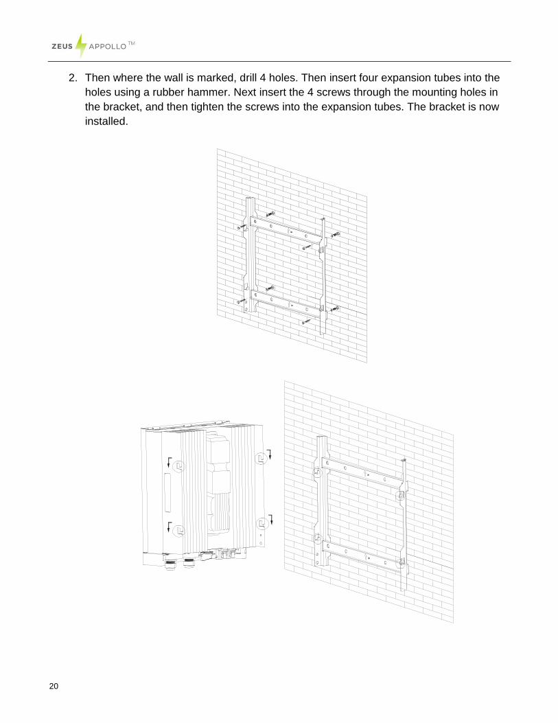
2. Then where the wall is marked, drill 4 holes. Then insert four expansion tubes into the
holes using a rubber hammer. Next insert the 4 screws through the mounting holes in
the bracket, and then tighten the screws into the expansion tubes. The bracket is now
installed.
21
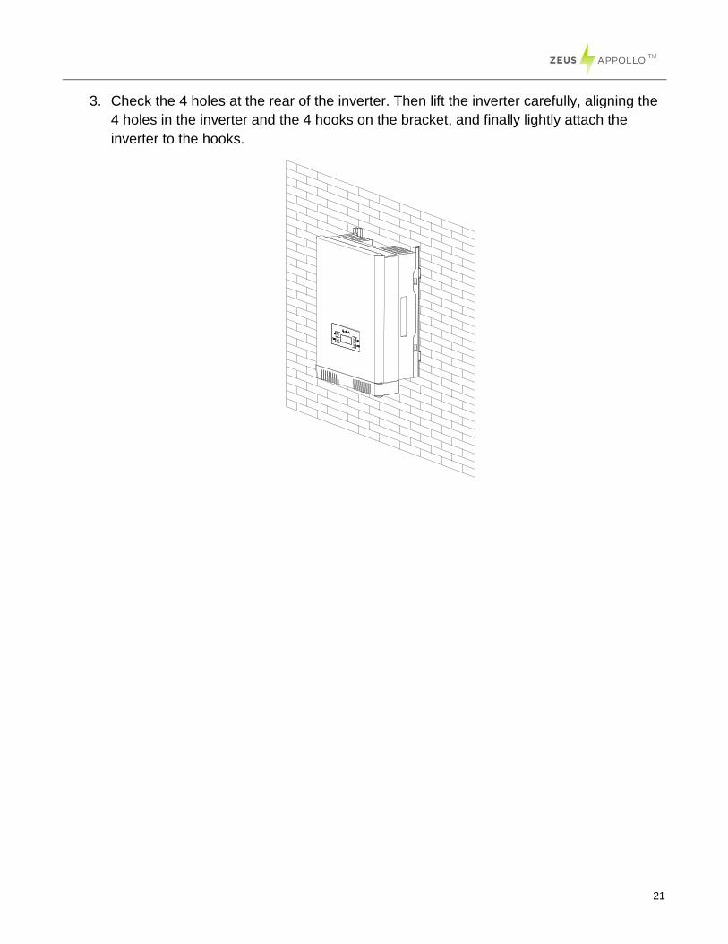
3. Check the 4 holes at the rear of the inverter. Then lift the inverter carefully, aligning the
4 holes in the inverter and the 4 hooks on the bracket, and finally lightly attach the
inverter to the hooks.
22
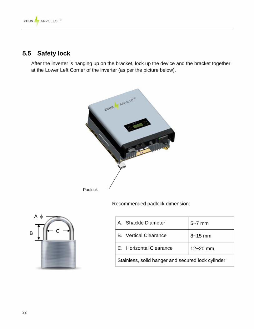
5.5 Safety lock
After the inverter is hanging up on the bracket, lock up the device and the bracket together
at the Lower Left Corner of the inverter (as per the picture below).
Recommended padlock dimension:
A.Shackle Diameter 5~7 mm
B.Vertical Clearance 8~15 mm
C.Horizontal Clearance 12~20 mm
Stainless, solid hanger and secured lock cylinder
Padlock
C B
A

23
NOTICE
For further maintenance and possible repair, please keep the
key of the padlock in a safe place.
24
6. Electrical Connection
6.1 Safety
6.2 AC Side Connection
1. Integrated RCD and RCM
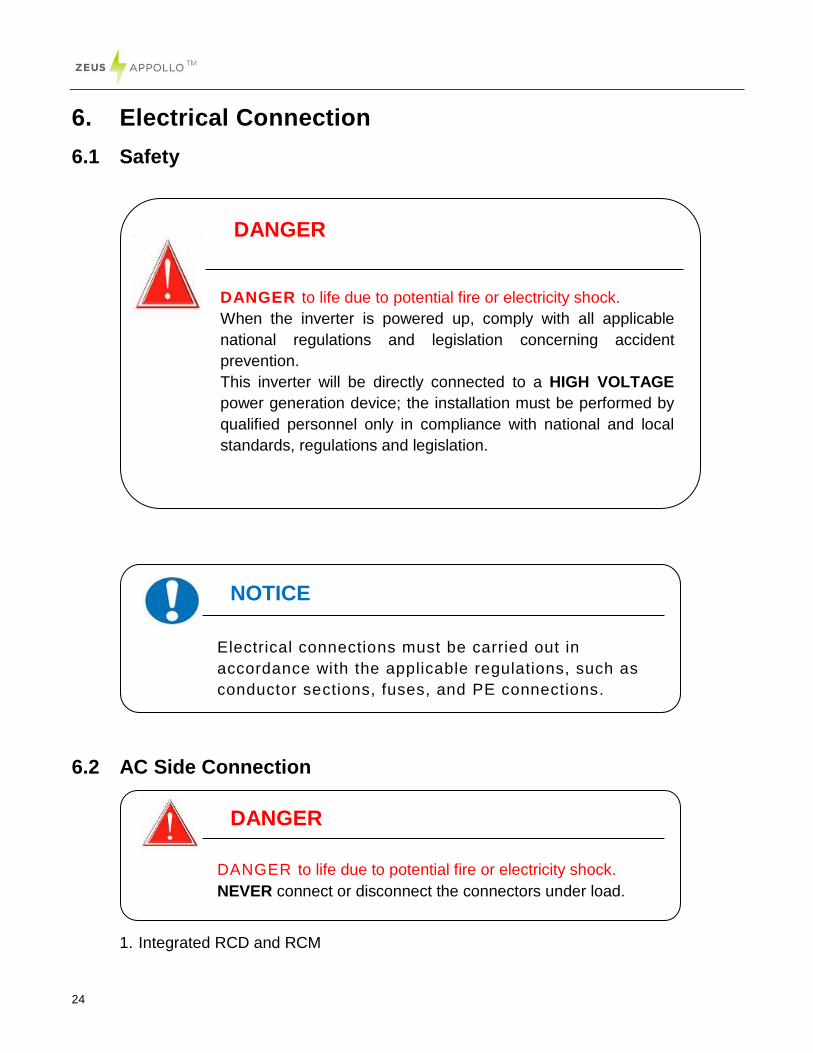
DANGER
DANGER to life due to potential fire or electricity shock.
NEVER connect or disconnect the connectors under load.
NOTICE
Electrical connections must be carried out in
accordance with the applicable regulations, such as
conductor sections, fuses, and PE connections.
DANGER
DANGER to life due to potential fire or electricity shock.
When the inverter is powered up, comply with all applicable
national regulations and legislation concerning accident
prevention.
This inverter will be directly connected to a HIGH VOLTAGE
power generation device; the installation must be performed by
qualified personnel only in compliance with national and local
standards, regulations and legislation.
25
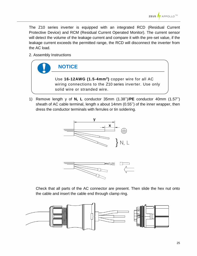
The Z10 series inverter is equipped with an integrated RCD (Residual Current
Protective Device) and RCM (Residual Current Operated Monitor). The current sensor
will detect the volume of the leakage current and compare it with the pre-set value, if the
leakage current exceeds the permitted range, the RCD will disconnect the inverter from
the AC load.
2. Assembly Instructions
1) Remove length y of N, L conductor 35mm (1.38’’)/PE conductor 40mm (1.57’’)
sheath of AC cable terminal, length x about 14mm (0.55’’) of the inner wrapper, then
dress the conductor terminals with ferrules or tin soldering.
Check that all parts of the AC connector are present. Then slide the hex nut onto
the cable and insert the cable end through clamp ring.
NOTICE
Use 16-12AWG (1.5-4mm2) copper wire for all AC
wiring connections to the Z10 series inverter. Use only
solid wire or stranded wire.
26
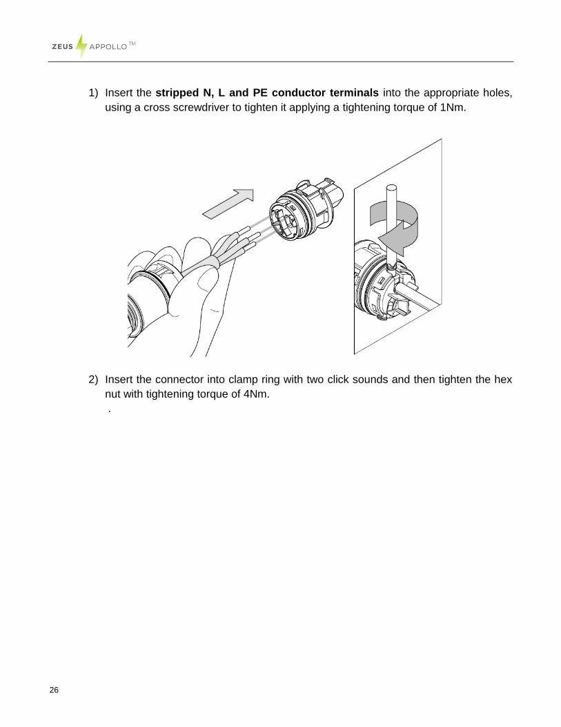
1) Insert the stripped N, L and PE conductor terminals into the appropriate holes,
using a cross screwdriver to tighten it applying a tightening torque of 1Nm.
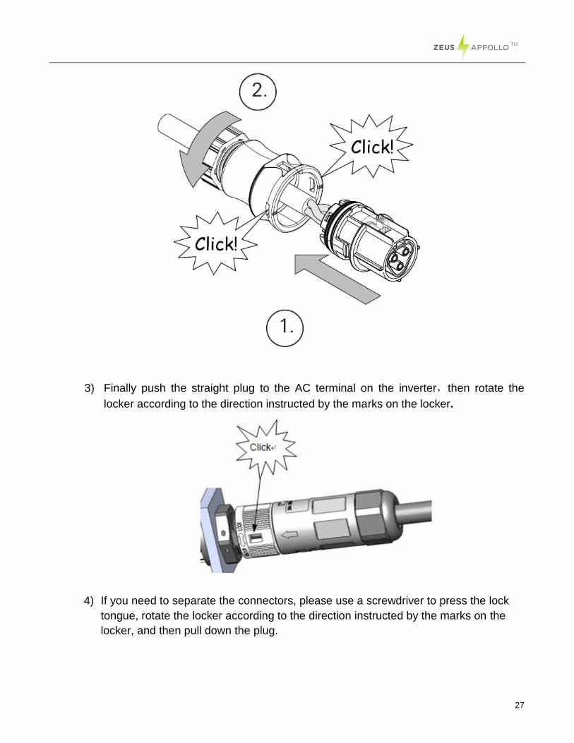
2) Insert the connector into clamp ring with two click sounds and then tighten the hex
nut with tightening torque of 4Nm.
.
27
3) Finally push the straight plug to the AC terminal on the inverter,then rotate the
locker according to the direction instructed by the marks on the locker.
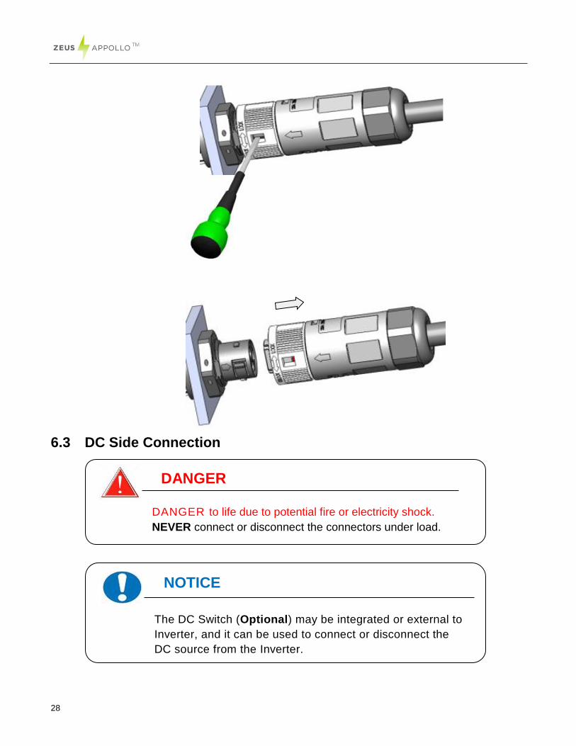
4) If you need to separate the connectors, please use a screwdriver to press the lock
tongue, rotate the locker according to the direction instructed by the marks on the
locker, and then pull down the plug.
28
6.3 DC Side Connection
NOTICE
The DC Switch (Optional) may be integrated or external to
Inverter, and it can be used to connect or disconnect the
DC source from the Inverter.
.
DANGER
DANGER to life due to potential fire or electricity shock.
NEVER connect or disconnect the connectors under load.
29
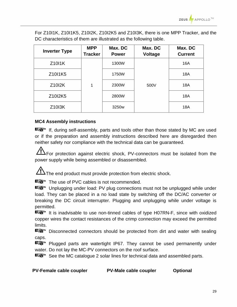
For Z10I1K, Z10I1K5, Z10I2K, Z10I2K5 and Z10I3K, there is one MPP Tracker, and the
DC characteristics of them are illustrated as the following table.
Inverter Type MPP
Tracker
Max. DC
Power
Max. DC
Voltage
Max. DC
Current
Z10I1K
1
1300W
500V
16A
Z10I1K5 1750W 18A
Z10I2K 2300W 18A
Z10I2K5 2800W 18A
Z10I3K 3250w 18A
MC4 Assembly instructions
If, during self-assembly, parts and tools other than those stated by MC are used
or if the preparation and assembly instructions described here are disregarded then
neither safety nor compliance with the technical data can be guaranteed.
For protection against electric shock, PV-connectors must be isolated from the
power supply while being assembled or disassembled.
The end product must provide protection from electric shock.
The use of PVC cables is not recommended.
Unplugging under load: PV plug connections must not be unplugged while under
load. They can be placed in a no load state by switching off the DC/AC converter or
breaking the DC circuit interrupter. Plugging and unplugging while under voltage is
permitted.
It is inadvisable to use non-tinned cables of type H07RN-F, since with oxidized
copper wires the contact resistances of the crimp connection may exceed the permitted
limits.
Disconnected connectors should be protected from dirt and water with sealing
caps.
Plugged parts are watertight IP67. They cannot be used permanently under
water. Do not lay the MC-PV connectors on the roof surface.
See the MC catalogue 2 solar lines for technical data and assembled parts.
PV-Female cable coupler PV-Male cable coupler Optional
30
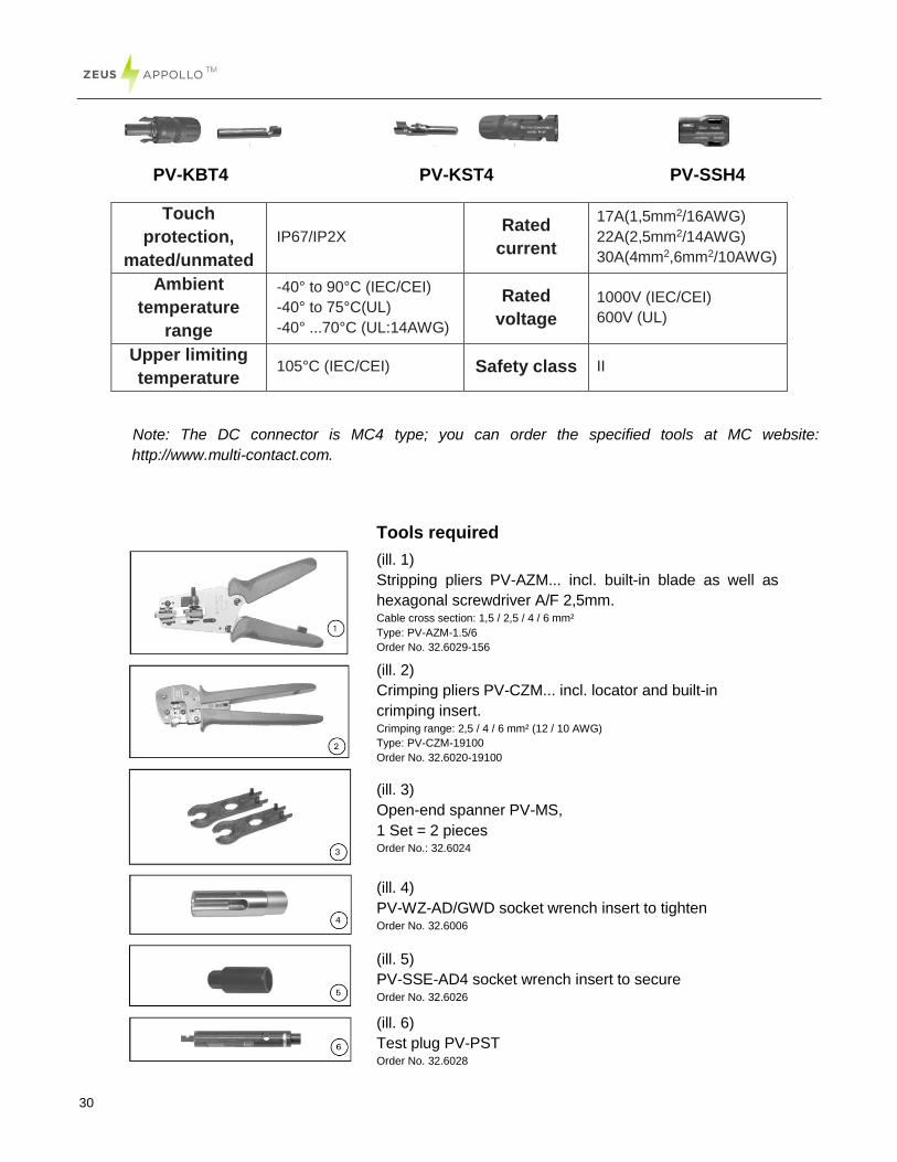
PV-KBT4 PV-KST4 PV-SSH4
Touch
protection,
mated/unmated
IP67/IP2X Rated
current
17A(1,5mm2/16AWG)
22A(2,5mm2/14AWG)
30A(4mm2,6mm2/10AWG)
Ambient
temperature
range
-40° to 90°C (IEC/CEI)
-40° to 75°C(UL)
-40° ...70°C (UL:14AWG)
Rated
voltage
1000V (IEC/CEI)
600V (UL)
Upper limiting
temperature 105°C (IEC/CEI) Safety class II
Note: The DC connector is MC4 type; you can order the specified tools at MC website:
http://www.multi-contact.com.
Tools required
(ill. 1)
Stripping pliers PV-AZM... incl. built-in blade as well as
hexagonal screwdriver A/F 2,5mm. Cable cross section: 1,5 / 2,5 / 4 / 6 mm²
Type: PV-AZM-1.5/6
Order No. 32.6029-156
(ill. 2)
Crimping pliers PV-CZM... incl. locator and built-in
crimping insert. Crimping range: 2,5 / 4 / 6 mm² (12 / 10 AWG)
Type: PV-CZM-19100
Order No. 32.6020-19100
(ill. 3)
Open-end spanner PV-MS,
1 Set = 2 pieces Order No.: 32.6024
(ill. 4)
PV-WZ-AD/GWD socket wrench insert to tighten Order No. 32.6006
(ill. 5)
PV-SSE-AD4 socket wrench insert to secure Order No. 32.6026
(ill. 6)
Test plug PV-PST Order No. 32.6028
31
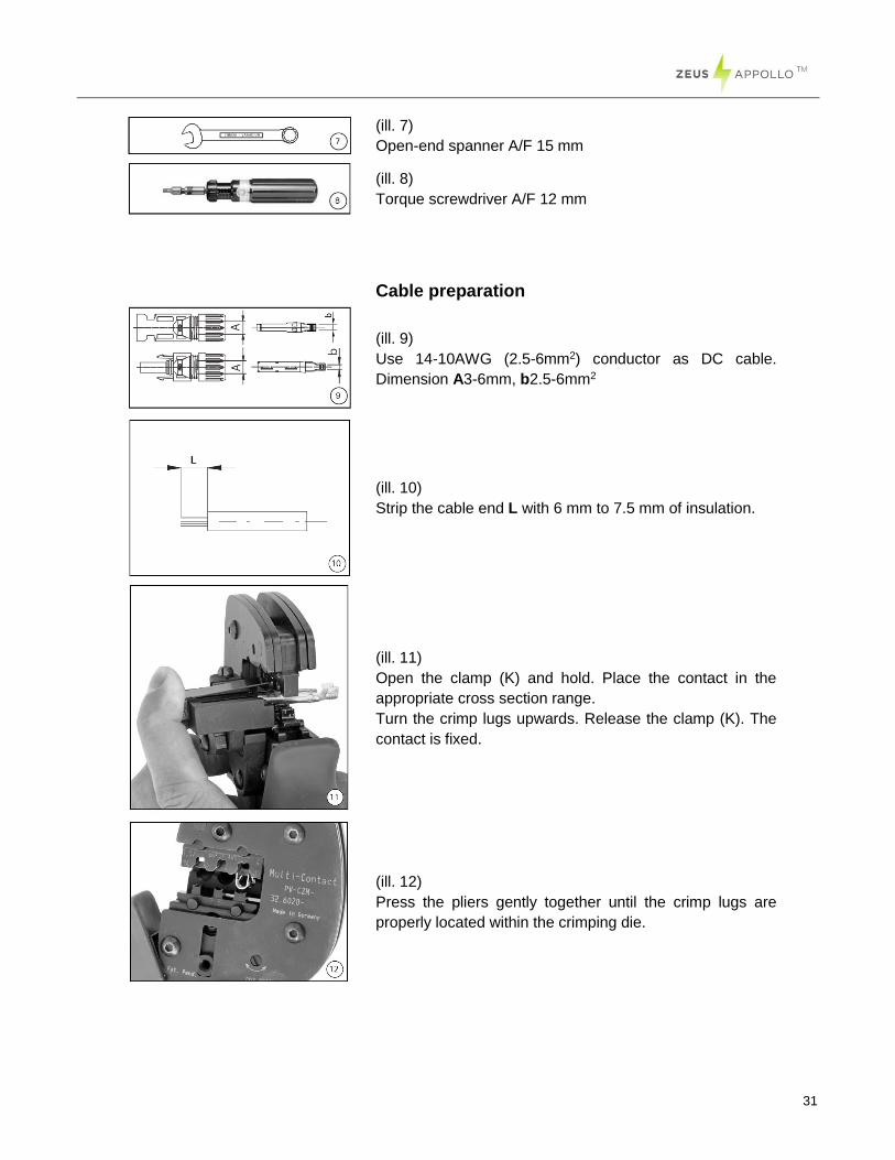
(ill. 7)
Open-end spanner A/F 15 mm
(ill. 8)
Torque screwdriver A/F 12 mm
Cable preparation
(ill. 9)
Use 14-10AWG (2.5-6mm2) conductor as DC cable.
Dimension A3-6mm, b2.5-6mm2
(ill. 10)
Strip the cable end L with 6 mm to 7.5 mm of insulation.
(ill. 11)
Open the clamp (K) and hold. Place the contact in the
appropriate cross section range.
Turn the crimp lugs upwards. Release the clamp (K). The
contact is fixed.
(ill. 12)
Press the pliers gently together until the crimp lugs are
properly located within the crimping die.
32
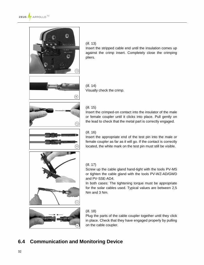
(ill. 13)
Insert the stripped cable end until the insulation comes up
against the crimp insert. Completely close the crimping
pliers.
(ill. 14)
Visually check the crimp.
(ill. 15)
Insert the crimped-on contact into the insulator of the male
or female coupler until it clicks into place. Pull gently on
the lead to check that the metal part is correctly engaged.
(ill. 16)
Insert the appropriate end of the test pin into the male or
female coupler as far as it will go. If the contact is correctly
located, the white mark on the test pin must still be visible.
(ill. 17)
Screw up the cable gland hand-tight with the tools PV-MS
or tighten the cable gland with the tools PV-WZ-AD/GWD
and PV-SSE-AD4.
In both cases: The tightening torque must be appropriate
for the solar cables used. Typical values are between 2,5
Nm and 3 Nm.
(ill. 18)
Plug the parts of the cable coupler together until they click
in place. Check that they have engaged properly by pulling
on the cable coupler.
6.4 Communication and Monitoring Device
33
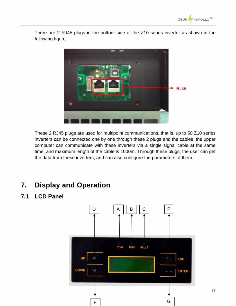
There are 2 RJ45 plugs in the bottom side of the Z10 series inverter as shown in the
following figure:
These 2 RJ45 plugs are used for multipoint communications, that is, up to 50 Z10 series
inverters can be connected one by one through these 2 plugs and the cables, the upper
computer can communicate with these inverters via a single signal cable at the same
time, and maximum length of the cable is 1000m. Through these plugs, the user can get
the data from these inverters, and can also configure the parameters of them.
7. Display and Operation
7.1 LCD Panel
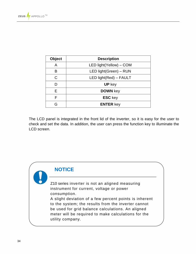
D A B C F
E G
34
Object Description
A LED light(Yellow) – COM
B LED light(Green) – RUN
C LED light(Red) – FAULT
D UP key
E DOWN key
F ESC key
G ENTER key
The LCD panel is integrated in the front lid of the inverter, so it is easy for the user to
check and set the data. In addition, the user can press the function key to illuminate the
LCD screen.
NOTICE
Z10 series inverter is not an aligned measuring
instrument for current, voltage or power
consumption.
A slight deviation of a few percent points is inherent
to the system; the results from the inverter cannot
be used for grid balance calculations. An aligned
meter will be required to make calculations for the
utility company.
35
7.2 Commissioning
A minimum available voltage of 150Vdc and a DC power of >10Wdc is required before
the inverter starts feeding power to the grid.
AC side: Turn on the AC circuit breaker and the display module will works.
DC side: Turn on the DC switch.
When the inverter is started for the first time, a menu is displayed to choose the
language and the country where the inverter installed, English, Dutch and German are
available for display.
7.3 Operation
7.3.1 System operation interface
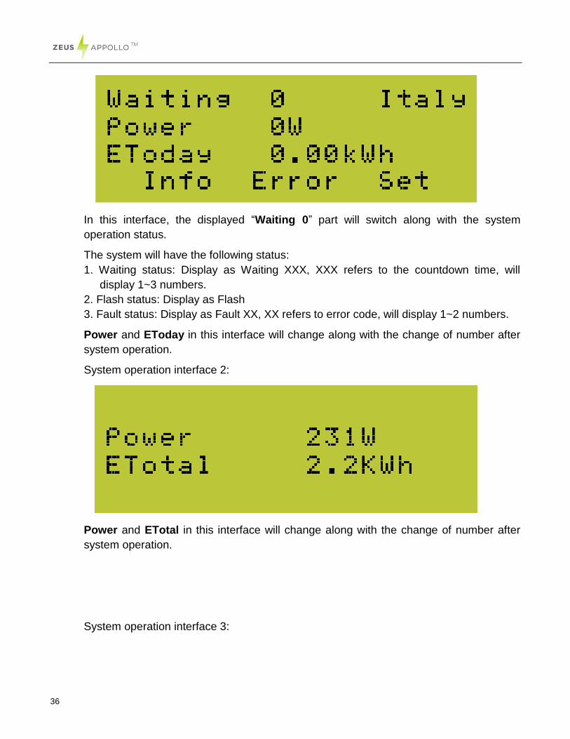
System operation interface 1:
NOTICE
You need to ensure that you have selected the correct country
so that local safety compliance is maintained.
NOTICE
The power supply of the display module is accessed through the
AC grid, so the screen will not be available until AC is
connected.
36
In this interface, the displayed “Waiting 0” part will switch along with the system
operation status.
The system will have the following status:
1. Waiting status: Display as Waiting XXX, XXX refers to the countdown time, will
display 1~3 numbers.
2. Flash status: Display as Flash
3. Fault status: Display as Fault XX, XX refers to error code, will display 1~2 numbers.
Power and EToday in this interface will change along with the change of number after
system operation.
System operation interface 2:
Power and ETotal in this interface will change along with the change of number after
system operation.
System operation interface 3:
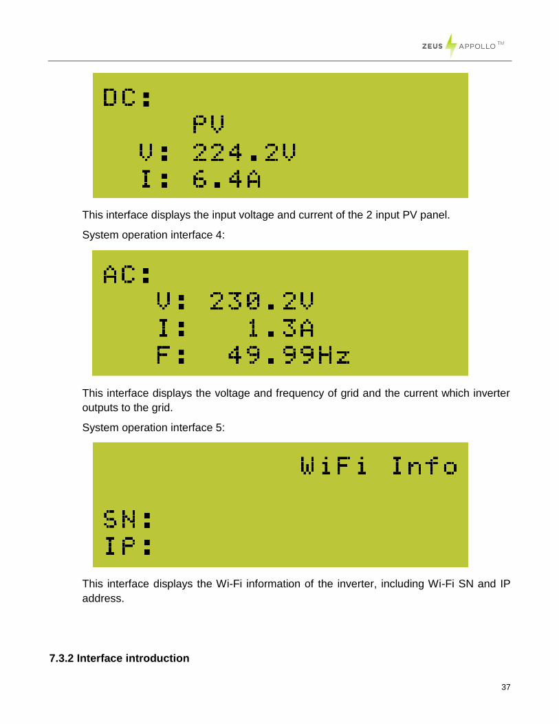
37
This interface displays the input voltage and current of the 2 input PV panel.
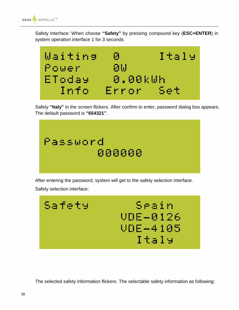
System operation interface 4:
This interface displays the voltage and frequency of grid and the current which inverter
outputs to the grid.
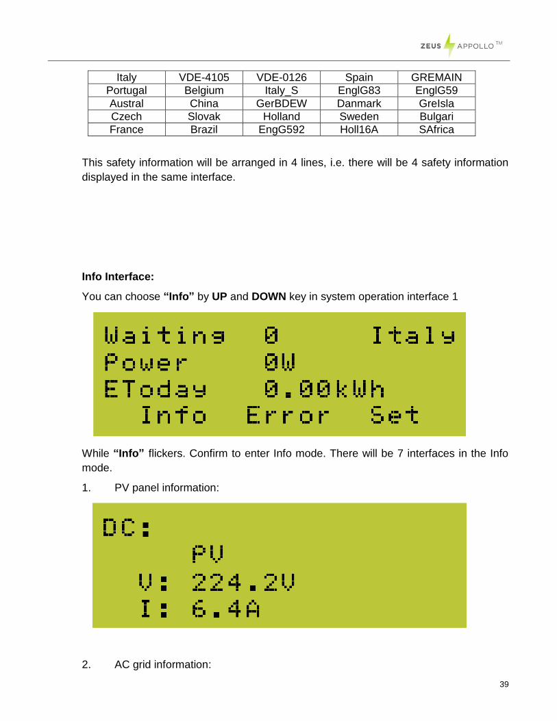
System operation interface 5:
This interface displays the Wi-Fi information of the inverter, including Wi-Fi SN and IP
address.
7.3.2 Interface introduction
38
Safety Interface: When choose “Safety” by pressing compound key (ESC+ENTER) in
system operation interface 1 for 3 seconds
Safety “Italy” in the screen flickers. After confirm to enter, password dialog box appears.
The default password is “654321”.
After entering the password, system will get to the safety selection interface.
Safety selection interface:
The selected safety information flickers. The selectable safety information as following:
39
Italy VDE-4105 VDE-0126 Spain GREMAIN
Portugal Belgium Italy_S EnglG83 EnglG59
Austral China GerBDEW Danmark GreIsla
Czech Slovak Holland Sweden Bulgari
France Brazil EngG592 Holl16A SAfrica
This safety information will be arranged in 4 lines, i.e. there will be 4 safety information
displayed in the same interface.
Info Interface:
You can choose “Info” by UP and DOWN key in system operation interface 1
While “Info” flickers. Confirm to enter Info mode. There will be 7 interfaces in the Info
mode.
1. PV panel information:
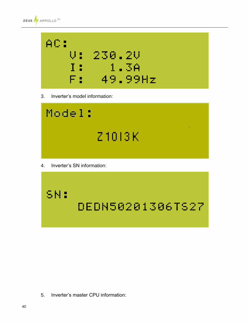
2. AC grid information:
40
3. Inverter’s model information:
4. Inverter’s SN information:
5. Inverter’s master CPU information:
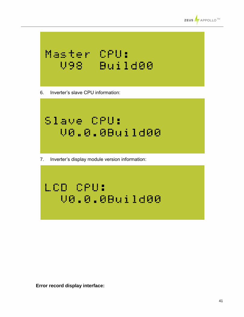
41
6. Inverter’s slave CPU information:
7. Inverter’s display module version information:
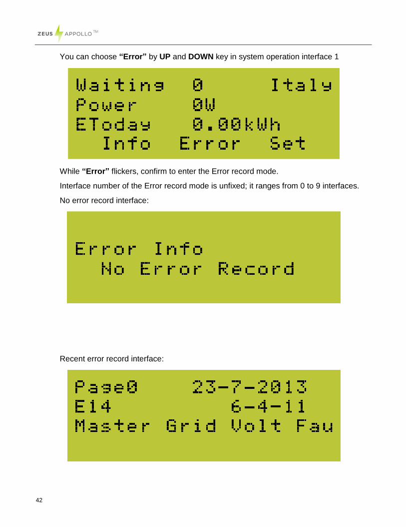
Error record display interface:
42
You can choose “Error” by UP and DOWN key in system operation interface 1
While “Error” flickers, confirm to enter the Error record mode.
Interface number of the Error record mode is unfixed; it ranges from 0 to 9 interfaces.
No error record interface:
Recent error record interface:
43
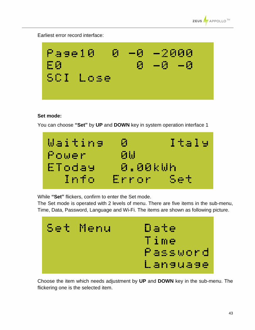
Earliest error record interface:
Set mode:
You can choose “Set” by UP and DOWN key in system operation interface 1
While “Set” flickers, confirm to enter the Set mode.
The Set mode is operated with 2 levels of menu. There are five items in the sub-menu,
Time, Data, Password, Language and Wi-Fi. The items are shown as following picture.
Choose the item which needs adjustment by UP and DOWN key in the sub-menu. The
flickering one is the selected item.

44
Setting Language:
In the Set mode, choose Language by Up and Down key (as shown in the picture)
While “Language” flickers, confirm to enter the language option list.
Choose the target language, the corresponding language flickers. English, Dutch and
German are available for displaying. Click ENTER to save data and back to prior menu.
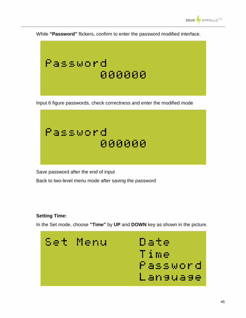
Changing Password:
In the Set mode, choose “Password” by UP and DOWN key as shown in the picture.
45
While “Password” flickers, confirm to enter the password modified interface.
Input 6 figure passwords, check correctness and enter the modified mode
Save password after the end of input
Back to two-level menu mode after saving the password
Setting Time:
In the Set mode, choose “Time” by UP and DOWN key as shown in the picture.
46
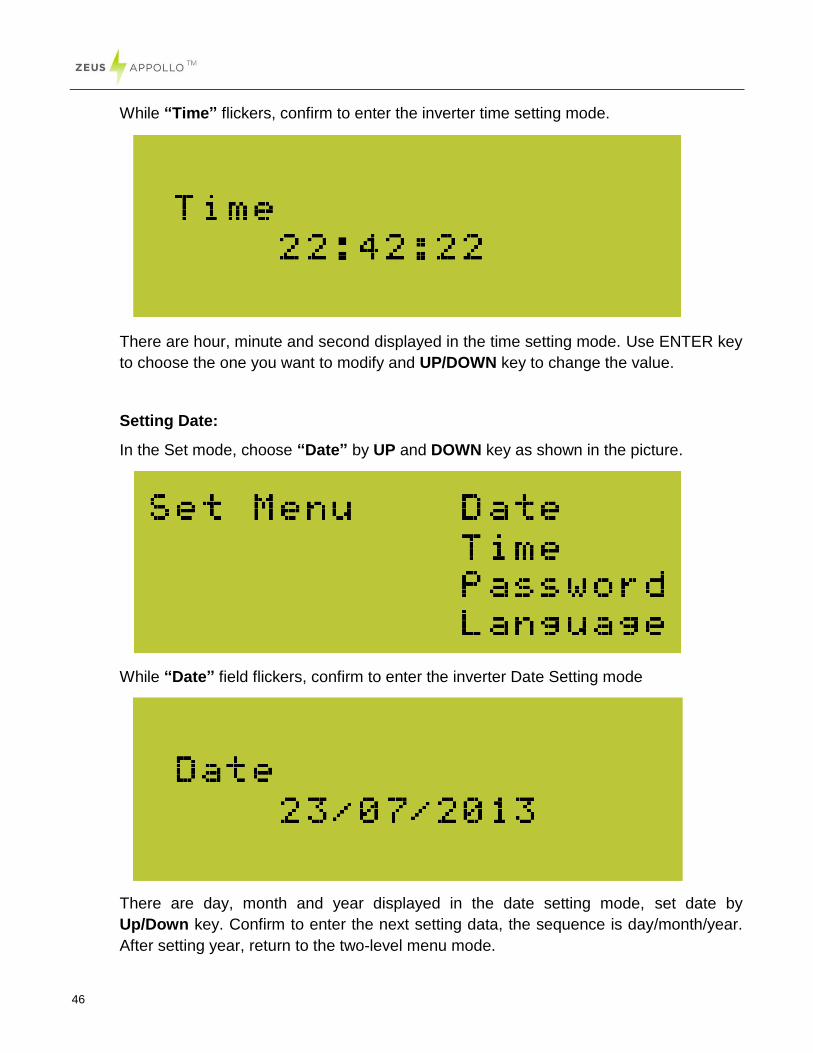
While “Time” flickers, confirm to enter the inverter time setting mode.
There are hour, minute and second displayed in the time setting mode. Use ENTER key
to choose the one you want to modify and UP/DOWN key to change the value.
Setting Date:
In the Set mode, choose “Date” by UP and DOWN key as shown in the picture.
While “Date” field flickers, confirm to enter the inverter Date Setting mode
There are day, month and year displayed in the date setting mode, set date by
Up/Down key. Confirm to enter the next setting data, the sequence is day/month/year.
After setting year, return to the two-level menu mode.
47
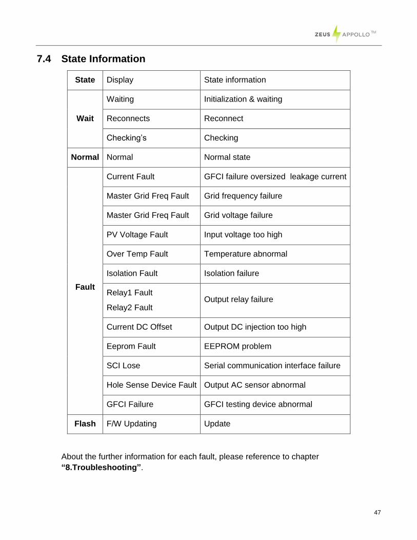
7.4 State Information
State Display State information
Wait
Waiting Initialization & waiting
Reconnects Reconnect
Checking’s Checking
Normal Normal Normal state
Fault
Current Fault GFCI failure oversized leakage current
Master Grid Freq Fault Grid frequency failure
Master Grid Freq Fault Grid voltage failure
PV Voltage Fault Input voltage too high
Over Temp Fault Temperature abnormal
Isolation Fault Isolation failure
Relay1 Fault
Relay2 Fault Output relay failure
Current DC Offset Output DC injection too high
Eeprom Fault EEPROM problem
SCI Lose Serial communication interface failure
Hole Sense Device Fault Output AC sensor abnormal
GFCI Failure GFCI testing device abnormal
Flash F/W Updating Update
About the further information for each fault, please reference to chapter
“8.Troubleshooting”.
48
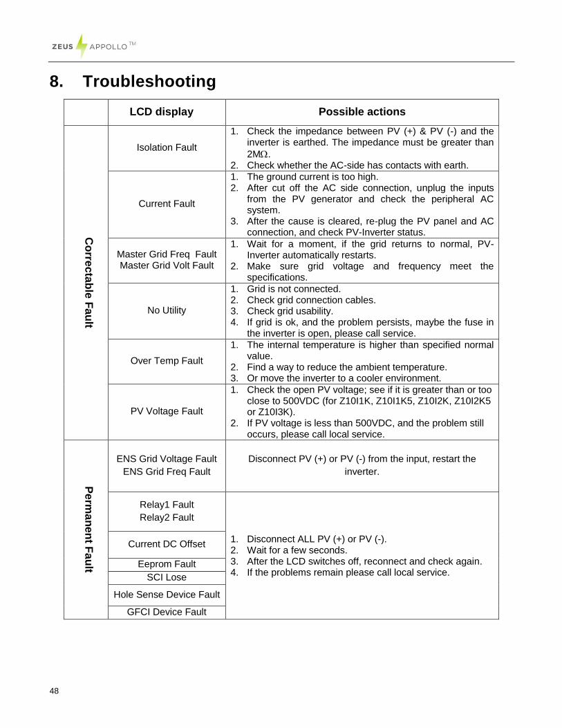
8. Troubleshooting
LCD display Possible actions
Co
rrec
tab
le F
au
lt
Isolation Fault
1. Check the impedance between PV (+) & PV (-) and the inverter is earthed. The impedance must be greater than
2M. 2. Check whether the AC-side has contacts with earth.
Current Fault
1. The ground current is too high. 2. After cut off the AC side connection, unplug the inputs
from the PV generator and check the peripheral AC system.
3. After the cause is cleared, re-plug the PV panel and AC connection, and check PV-Inverter status.
Master Grid Freq Fault Master Grid Volt Fault
1. Wait for a moment, if the grid returns to normal, PV-Inverter automatically restarts.
2. Make sure grid voltage and frequency meet the specifications.
No Utility
1. Grid is not connected. 2. Check grid connection cables. 3. Check grid usability. 4. If grid is ok, and the problem persists, maybe the fuse in
the inverter is open, please call service.
Over Temp Fault
1. The internal temperature is higher than specified normal value.
2. Find a way to reduce the ambient temperature. 3. Or move the inverter to a cooler environment.
PV Voltage Fault
1. Check the open PV voltage; see if it is greater than or too close to 500VDC (for Z10I1K, Z10I1K5, Z10I2K, Z10I2K5 or Z10I3K).
2. If PV voltage is less than 500VDC, and the problem still occurs, please call local service.
Pe
rma
ne
nt F
au
lt
ENS Grid Voltage Fault
ENS Grid Freq Fault
Disconnect PV (+) or PV (-) from the input, restart the
inverter.
Relay1 Fault
Relay2 Fault
1. Disconnect ALL PV (+) or PV (-). 2. Wait for a few seconds. 3. After the LCD switches off, reconnect and check again. 4. If the problems remain please call local service.
Current DC Offset
Eeprom Fault
SCI Lose
Hole Sense Device Fault
GFCI Device Fault
49
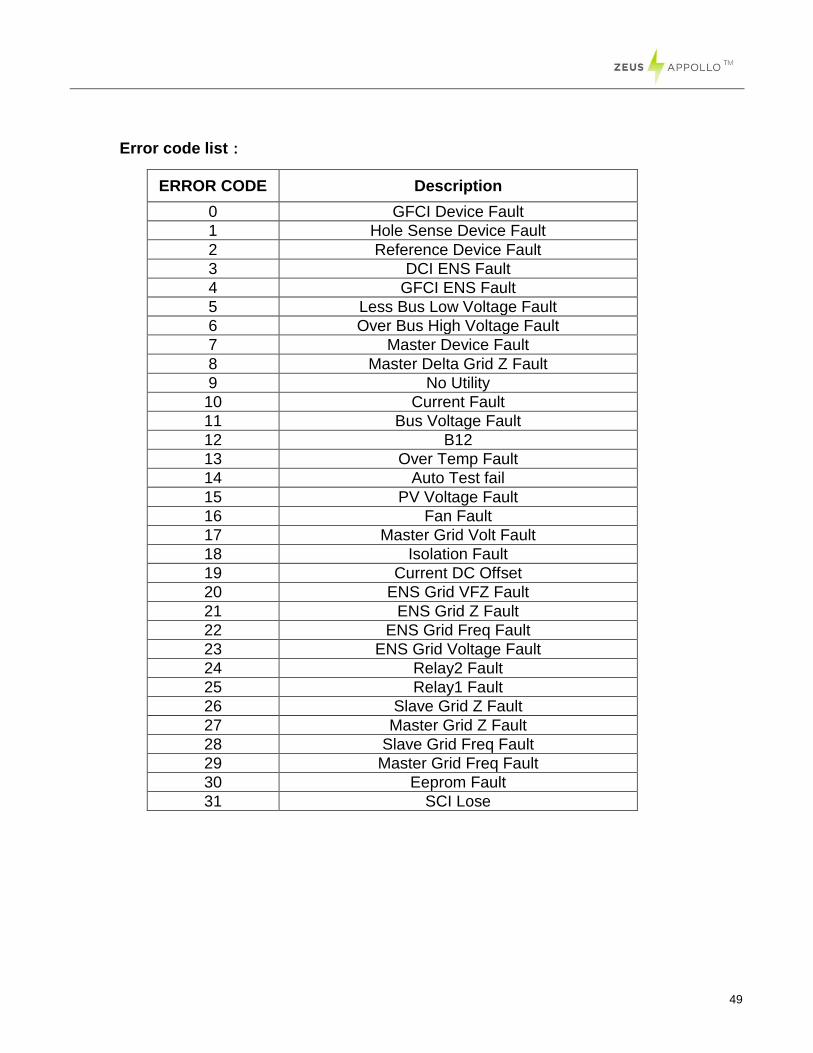
Error code list:
ERROR CODE Description
0 GFCI Device Fault
1 Hole Sense Device Fault
2 Reference Device Fault
3 DCI ENS Fault
4 GFCI ENS Fault
5 Less Bus Low Voltage Fault
6 Over Bus High Voltage Fault
7 Master Device Fault
8 Master Delta Grid Z Fault
9 No Utility
10 Current Fault
11 Bus Voltage Fault
12 B12
13 Over Temp Fault
14 Auto Test fail
15 PV Voltage Fault
16 Fan Fault
17 Master Grid Volt Fault
18 Isolation Fault
19 Current DC Offset
20 ENS Grid VFZ Fault
21 ENS Grid Z Fault
22 ENS Grid Freq Fault
23 ENS Grid Voltage Fault
24 Relay2 Fault
25 Relay1 Fault
26 Slave Grid Z Fault
27 Master Grid Z Fault
28 Slave Grid Freq Fault
29 Master Grid Freq Fault
30 Eeprom Fault
31 SCI Lose
50
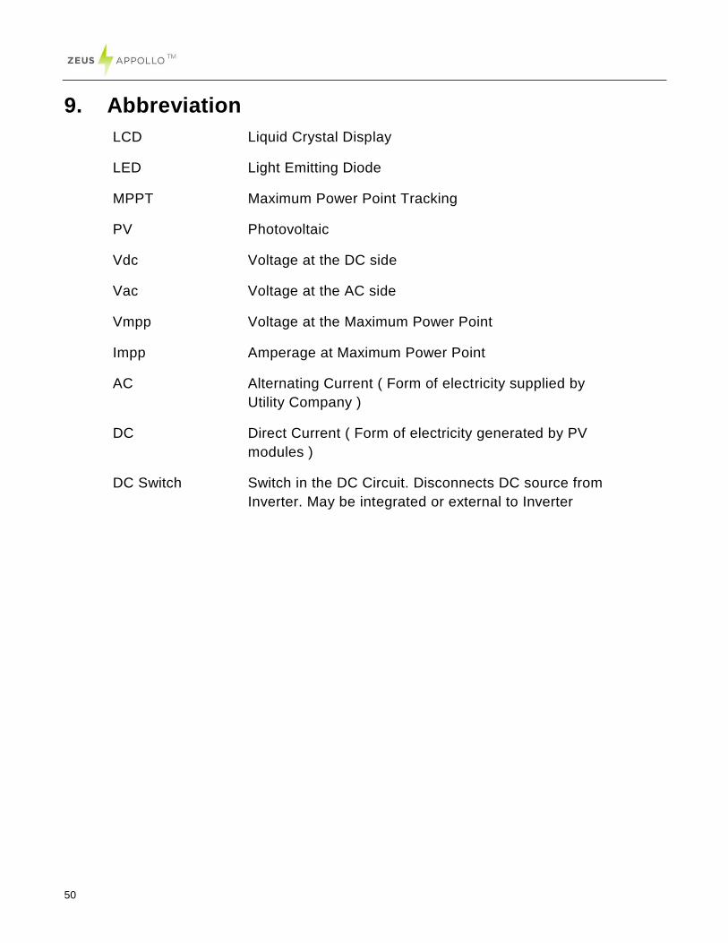
9. Abbreviation
LCD Liquid Crystal Display
LED Light Emitting Diode
MPPT Maximum Power Point Tracking
PV Photovoltaic
Vdc Voltage at the DC side
Vac Voltage at the AC side
Vmpp Voltage at the Maximum Power Point
Impp Amperage at Maximum Power Point
AC Alternating Current ( Form of electricity supplied by
Utility Company )
DC Direct Current ( Form of electricity generated by PV
modules )
DC Switch Switch in the DC Circuit. Disconnects DC source from
Inverter. May be integrated or external to Inverter
51
10. Contact
Beijing Hua Xin Liu He Investment (Australia) Pty Ltd.
Website: www.zeusappollo.com
Perth Office
789 Wellington Street, West Perth, WA, 6005
Phone: (08) 6311 9906
Email: [email protected]
Brisbane Office
32 Crockford Street Banyo, QLD 4014
Phone: (07) 3123 6148
Fax: (07) 3266 4758
Email: [email protected]