Embed Size (px)
Citation preview

Page 1 of 33
U
sag
e.
Ap
pli
ca
tio
n. P
rac
tic
e.
User manual
Syst
em
s. C
ont
rols
. Se
nso
rs.
© by TRsystems GmbH • 75179 Pforzheim • www.unidor.de • Tel.: (+49) (0)7231/3152 0
smartDIE-PRO 6
TRsystems GmbH
D-75179 Pforzheim Freiburger Straße 3
Phone: (+49) (0)7231/31520 Fax: (+49) (0)7231/315299
[email protected] www.trsystems.de | www.unidor.de
6-channel die protection device with teach-in
function and graphical event indication

Page 2 of 33
U
sag
e.
Ap
pli
ca
tio
n. P
rac
tic
e.
User manual
Syst
em
s. C
ont
rols
. Se
nso
rs.
© by TRsystems GmbH • 75179 Pforzheim • www.unidor.de • Tel.: (+49) (0)7231/3152 0
© by unidor TRsystems GmbH D-75179 Pforzheim Freiburger Straße 3 Phone: (+49) (0)7231/31520 Fax: (+49) (0)7231/315299 [email protected] www.trsystems.de | www.unidor.de
Copyright protection
This manual, including the images contained therein, are protected under copyright law. Third-party applications of this manual which violate copyright provisions are prohibited. Reproduction, translation and electronic and photographic archiving and alteration require written consent of the manufacturer. Legal action will be taken against violations and corresponding claims for damages will be asserted.
Subject to changes
Subject to changes in the interests of technical advancement.
Document information
Issue/rev. date: 00 / 7 Oct. 2014 Document/rev. no.: 00 File name: smartDIE-PRO6_Manual_EN_V00.docx Author: SPA / SW
Font types
Italic or bold font refers to the title of a document or is used to highlight text.
Courier font refers to text which is shown on the display and/or screen as well as to menu options of software.
< > refers to keys of the keyboard of your computer (such as <RETURN>).

Page 3 of 33
U
sag
e.
Ap
pli
ca
tio
n. P
rac
tic
e.
User manual
Syst
em
s. C
ont
rols
. Se
nso
rs.
© by TRsystems GmbH • 75179 Pforzheim • www.unidor.de • Tel.: (+49) (0)7231/3152 0
Table of contents
Table of contents ................................................................................................................................ 3
1 Change index .................................................................................................................................... 5
2 General ............................................................................................................................................. 6
2.1 Scope of application ................................................................................................................ 6
3 Additional safety notes .................................................................................................................... 7
3.1 Definition of icons and notes ................................................................................................... 7
3.2 Supplement notes to the intended use ................................................................................... 7
3.3 Organizational measures ......................................................................................................... 7
4 Technical data .................................................................................................................................. 8
4.1 Functional scope ...................................................................................................................... 8
4.2 Scope of delivery ..................................................................................................................... 9
4.3 Electrical specifications ............................................................................................................ 9
4.3.1 smartDIE-PRO 6 ............................................................................................................... 9
4.3.2 Beckhoff socket (EP2338-0001) ..................................................................................... 10
4.4 Dimensions and accessories .................................................................................................. 10
4.4.1 smartDIE-PRO 6 ............................................................................................................. 10
4.4.2 Wall mount .................................................................................................................... 11
4.4.3 Beckhoff socket (EP2338-0001) ..................................................................................... 11
5 Wiring diagram .............................................................................................................................. 12
5.1 General drawing .................................................................................................................... 12
5.2 smartDIE-PRO 6 ..................................................................................................................... 13
5.3 Beckhoff socket (EP2338-0001) ............................................................................................. 14
5.4 Connection cable ................................................................................................................... 15
6 Basic screen.................................................................................................................................... 18
6.1 Graphical event indication ..................................................................................................... 19
6.2 Status, error and bridging indication ..................................................................................... 20
7 Authorize ........................................................................................................................................ 21
7.1 Standard passwords & user level .......................................................................................... 21
8 Programming function ................................................................................................................... 22
9.1 Programming and/or parameterizing of a die protection input ........................................... 22
9.2 Programming the monitoring function in the "dynamic" monitoring type .......................... 23
9.3 Error messages during operation .......................................................................................... 23
9.3.1 Possible error messages during static monitoring: ....................................................... 23
9.3.2 Possible error messages during dynamic monitoring: .................................................. 24
9.3.3 Error messages of the cam monitoring function ........................................................... 24
10 Commissioning function .............................................................................................................. 25
11 Counter ........................................................................................................................................ 26

Page 4 of 33
U
sag
e.
Ap
pli
ca
tio
n. P
rac
tic
e.
User manual
Syst
em
s. C
ont
rols
. Se
nso
rs.
© by TRsystems GmbH • 75179 Pforzheim • www.unidor.de • Tel.: (+49) (0)7231/3152 0
12 Die administration ....................................................................................................................... 27
12.1 Basic screen of the die administration ................................................................................ 27
12.2 Select die ............................................................................................................................. 28
12.3 Create new die ..................................................................................................................... 29
12.4 Activate/select existing die .................................................................................................. 31
12.5 Delete available die ............................................................................................................. 32
13 EC Declaration of Conformity ...................................................................................................... 33

Page 5 of 33
U
sag
e.
Ap
pli
ca
tio
n. P
rac
tic
e.
User manual
Syst
em
s. C
ont
rols
. Se
nso
rs.
© by TRsystems GmbH • 75179 Pforzheim • www.unidor.de • Tel.: (+49) (0)7231/3152 0
1 Change index
Change Date Index
First edition 7 Oct. 2014 00

Page 6 of 33
U
sag
e.
Ap
pli
ca
tio
n. P
rac
tic
e.
User manual
Syst
em
s. C
ont
rols
. Se
nso
rs.
© by TRsystems GmbH • 75179 Pforzheim • www.unidor.de • Tel.: (+49) (0)7231/3152 0
2 General
This user manual contains the following subjects:
- Electrical specifications
- Installation
- Commissioning
- Configuration/parameterization
Since the documentation has a modular structure, this user manual is deemed a supplement to other sources of documentation such as product data sheets, dimensional drawings, brochures and assembly instructions.
The user manual may form part of the scope of delivery depending on customer specifications or it may be requested separately.
These operating instructions are kept up-to-date. However, since TRsystems GmbH/UNIDOR products are subject to continuous further development, it is possible that short-term deviations between the device version and the operating instructions might occur due to technical changes. Please note that we do not assume liability for damage which might arise as a result.
2.1 Scope of application
This user manual solely applies to the following product:
smartDIE-PRO 6
Order number: 192101000000
The products are marked by attached nameplates and form part of a system.
Therefore, the following documentation applies:
- The system-specific operating instructions of the operator
- This user manual
- Further documents supplied together with system

Page 7 of 33
U
sag
e.
Ap
pli
ca
tio
n. P
rac
tic
e.
User manual
Syst
em
s. C
ont
rols
. Se
nso
rs.
© by TRsystems GmbH • 75179 Pforzheim • www.unidor.de • Tel.: (+49) (0)7231/3152 0
3 Additional safety notes
3.1 Definition of icons and notes
means that minor physical injury or property damage may occur if appropriate precautions are not taken.
refers to important information and/or characteristics of and application advice for the product used.
3.2 Supplement notes to the intended use
The system is designed to be used in Ethernet networks with a maximum speed of 100 Mbs for full-duplex operation specified in IEC 61158 as CPF2/2 (Communication Profile)
The technical directives on establishing the Ethernet network must be complied with in order to ensure safe operation.
The intended use also includes:
observing all notes contained in this user manual,
observing the assembly instructions, in particular the chapter "Fundamental safety notes" must be read and understood before beginning to work
3.3 Organizational measures
This user manual must always be available at the place of use of the system.
Before beginning work, the personnel assigned to perform activities on the system must have read and understood
– the assembly instructions, in particular the chapter "Fundamental safety notes", – and this user manual, in particular the chapter "Additional safety notes"
.
This particularly applies to temporary personnel.

Page 8 of 33
U
sag
e.
Ap
pli
ca
tio
n. P
rac
tic
e.
User manual
Syst
em
s. C
ont
rols
. Se
nso
rs.
© by TRsystems GmbH • 75179 Pforzheim • www.unidor.de • Tel.: (+49) (0)7231/3152 0
4 Technical data
Regarding the power supply for all hardware components with one power supply unit only, a power supply unit with the following specifications is required:
- Output voltage: 24 V DC (-15%/+20%) - Output current: min 2 A/max 4 A
Regarding a separate power supply for the smartDIE-PRO 6 and the Beckhoff modules, power supply units with the following specifications are required:
Power supply unit for the smartDIE-PRO 6: - Output voltage: 24 V DC (±20%) - Output current: min 1.5 A
Power supply unit for the Beckhoff modules: - Output voltage: 24 V DC (-15%/+20%) - Output current: max 4 A
If a power supply unit with an output current exceeding 4 A is used, the power supply for the Beckhoff modules (EP2338-0001) must be secured with a 4 A fuse as they could otherwise be damaged. (refer to chapter 4.3.2)
If all hardware components are supplied via one power supply unit only, the smartDIE-PRO 6 might also be switched off in the case of a short-circuit on one of the digital outputs/inputs.
4.1 Functional scope
6-channel die protection device with learning function and graphical event indication Monitoring types:
Off (no monitoring)
Static 0
Static 1
Dynamic Bridging function (internal + external) 6 cam inputs 2 piece counters (overall number of pieces + lot size) Input for "counter stop" Indication of the current stroke rate 2 separate stop outputs
Immediate stop
OT stop

Page 9 of 33
U
sag
e.
Ap
pli
ca
tio
n. P
rac
tic
e.
User manual
Syst
em
s. C
ont
rols
. Se
nso
rs.
© by TRsystems GmbH • 75179 Pforzheim • www.unidor.de • Tel.: (+49) (0)7231/3152 0
4.2 Scope of delivery
The following components are included in the standard scope of delivery:
Quantity:
Designation: Order no.:
Hardware components:
1 smartDIE-PRO 6 192101000000
1 smartDIE-PRO 6 wall mount, adjustable 49970480
1 USB data backup memory stick, 8 GB 63095320
2 EP2338-0001 EtherCAT box, 8 dig. inp. or 8 dig. outp. 781-20065
Power cable (M8 female/M8 male):
1 Power cable, ZK 2020-3132-0005 (0.5 m) 64060143
1 Power cable, ZK 2020-3132-0050 (5.0 m) 64060135
Power cable (M8 female/open end):
1 Power cable, M8-4/0-10 (10.0 m) 64060152
EtherCAT cable (M8 male/M8 male):
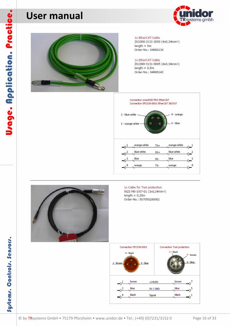
1 EtherCAT cable, ZK1090-3131-0005 (0.5 m) 64060142
1 EtherCAT cable, ZK1090-3131-3050 (5.0 m) 64060136
Miscellaneous:
1 DIG I/O cable PSA 4eC M8-3/0-10 (10 m) 64060141
8 M8/3-pin connec. plug *99-3379-100-03* 620001569
8 Protective cap M8 49250021
2 WZS M8-3/07-01 adapter cable WZS (0.20 m) 507050200002
4.3 Electrical specifications
4.3.1 smartDIE-PRO 6
Supply voltage: ............................... 24 V DC (±20%) Power input: ................................... max 1.5 A CPU: ................................................ Intel Atom D510 1.66 GHz RAM: ............................................... 2 GB Flash memory: ................................ 4 GB (without mechanical drive) Operating system: .......................... Windows Embedded XP Display: ........................................... 10.4" resistive LCD touch screen, 1024x768 pixels Bus interface: ................................. 1x RJ45 Ethernet (100BASE-TX)
1x M8 female EtherCAT (100BASE-TX) USB: ................................................ 2x USB 2.0 Dimensions: .................................... 240 x 66 x 215 mm (W x H x D) Weight: ........................................... 2200 g Installation:..................................... Table or wall mount Operating/storage temperature: ... 0..+45°C/-25..+70°C (non-condensing)

Page 10 of 33
U
sag
e.
Ap
pli
ca
tio
n. P
rac
tic
e.
User manual
Syst
em
s. C
ont
rols
. Se
nso
rs.
© by TRsystems GmbH • 75179 Pforzheim • www.unidor.de • Tel.: (+49) (0)7231/3152 0
4.3.2 Beckhoff socket (EP2338-0001)
Supply voltage: ............................... 24 V DC (-15%/+20%) Power supply/transfer: .................. max 4 A Power input: ................................... Us 120 mA
Up typ. 20 mA + load (max 0.5 A/output) Bus interface: ................................. 2x M8 female (EtherCAT) Channels: ........................................ 8 freely selectable digital inputs or outputs (M8 female) Input filter: ..................................... 10 µs "Log 0": ........................................... -3..+5 V "Log 1": ........................................... 11..30 V (6 mA input current) Output current: .............................. max 0.5 A Short-circuit current: ...................... typ. 1.5 A Dimensions: .................................... 30 x 126 x 26.5 mm (W x H x D) Weight: ........................................... 165 g Installation:..................................... 2x mounting holes ø 3 mm for M3 Operating/storage temperature: ... 0..+55°C/-25..+85°C
4.4 Dimensions and accessories
4.4.1 smartDIE-PRO 6
Page 11 of 33
U
sag
e.
Ap
pli
ca
tio
n. P
rac
tic
e.
User manual
Syst
em
s. C
ont
rols
. Se
nso
rs.
© by TRsystems GmbH • 75179 Pforzheim • www.unidor.de • Tel.: (+49) (0)7231/3152 0
4.4.2 Wall mount
4.4.3 Beckhoff socket (EP2338-0001)

Page 12 of 33
U
sag
e.
Ap
pli
ca
tio
n. P
rac
tic
e.
User manual
Syst
em
s. C
ont
rols
. Se
nso
rs.
© by TRsystems GmbH • 75179 Pforzheim • www.unidor.de • Tel.: (+49) (0)7231/3152 0
5 Wiring diagram
5.1 General drawing

Page 13 of 33
U
sag
e.
Ap
pli
ca
tio
n. P
rac
tic
e.
User manual
Syst
em
s. C
ont
rols
. Se
nso
rs.
© by TRsystems GmbH • 75179 Pforzheim • www.unidor.de • Tel.: (+49) (0)7231/3152 0
5.2 smartDIE-PRO 6

Page 14 of 33
U
sag
e.
Ap
pli
ca
tio
n. P
rac
tic
e.
User manual
Syst
em
s. C
ont
rols
. Se
nso
rs.
© by TRsystems GmbH • 75179 Pforzheim • www.unidor.de • Tel.: (+49) (0)7231/3152 0
5.3 Beckhoff socket (EP2338-0001)

Page 15 of 33
U
sag
e.
Ap
pli
ca
tio
n. P
rac
tic
e.
User manual
Syst
em
s. C
ont
rols
. Se
nso
rs.
© by TRsystems GmbH • 75179 Pforzheim • www.unidor.de • Tel.: (+49) (0)7231/3152 0
5.4 Connection cable
Page 16 of 33
U
sag
e.
Ap
pli
ca
tio
n. P
rac
tic
e.
User manual
Syst
em
s. C
ont
rols
. Se
nso
rs.
© by TRsystems GmbH • 75179 Pforzheim • www.unidor.de • Tel.: (+49) (0)7231/3152 0

Page 17 of 33
U
sag
e.
Ap
pli
ca
tio
n. P
rac
tic
e.
User manual
Syst
em
s. C
ont
rols
. Se
nso
rs.
© by TRsystems GmbH • 75179 Pforzheim • www.unidor.de • Tel.: (+49) (0)7231/3152 0

Page 18 of 33
U
sag
e.
Ap
pli
ca
tio
n. P
rac
tic
e.
User manual
Syst
em
s. C
ont
rols
. Se
nso
rs.
© by TRsystems GmbH • 75179 Pforzheim • www.unidor.de • Tel.: (+49) (0)7231/3152 0
6 Basic screen
The basic screen is used to graphically display events as well as to display current actual values of the die monitoring system. This page is also used to access the corresponding programming or parameterization screens of the system.
Indication of the current status of the die protection inputs as well as the additional inputs for Stop counter and Ext. bridge. This field may also be used to change to the "programming" screen (by simply touching the framed field on the touch screen).
Indication of the current status of the cam inputs as well as the inputs for Fast stop and TDC stop. This field may also be used to change to the "programming" screen (by simply touching the framed field on the touch screen).
Graphical event indication of the selected die protection input as well as the status of the assigned cam.
Indication of the current stroke rate (RPM).
Indication of the current counter reading of the lot and overall batch size. The "parameterization screen" of the batch size is opened by touching one of these fields.
1
2
3
4
5
1 2
3
4
5

Page 19 of 33
U
sag
e.
Ap
pli
ca
tio
n. P
rac
tic
e.
User manual
Syst
em
s. C
ont
rols
. Se
nso
rs.
© by TRsystems GmbH • 75179 Pforzheim • www.unidor.de • Tel.: (+49) (0)7231/3152 0
6.1 Graphical event indication
The graphical event indication displays the status of the signal transducer input (green curve) as well as the cam (yellow curve).
The currently selected input (1..6) may be selected using the arrow keys (1) right next to the display. The currently selected die protection input (2) as well as the corresponding cam (3) are displayed in the signal status indications with "<<<<<<<<".
As shown in the example above, the "die protection input number 2" as well as the correspondingly programmed "cam input number 4" are currently displayed.
The last cycle (or stroke) of the cam is always displayed. It is displayed in such a way that the end of the cam is shown at the end (right side) of the graphical display.
1
2
3

Page 20 of 33
U
sag
e.
Ap
pli
ca
tio
n. P
rac
tic
e.
User manual
Syst
em
s. C
ont
rols
. Se
nso
rs.
© by TRsystems GmbH • 75179 Pforzheim • www.unidor.de • Tel.: (+49) (0)7231/3152 0
6.2 Status, error and bridging indication
The message line(s) as well as the status and bridging indication of the die protection device are located at the bottom edge of the screen.
Caution: There is no automatic arming when bridged externally!
Example(s):
Die protection device bridged externally.
Die protection device has (at least) one error.
Die protection device bridged internally.
Message line 1 + 2
Status indication of the "die protection" (WZS) function. This indication/key allows the "die protection" function to be bridged when touched.
Possible indication(s):
Green = Everything is okay, die protection device active and error-free Red = There is at least one error Yellow = Bridged internally Orange = Bridged externally Flashing yellow = Die protection device in learning mode Blue = (Programming) value modified but not saved yet
Key for message window as well as acknowledgement key
1
2
3
1
2
3

Page 21 of 33
U
sag
e.
Ap
pli
ca
tio
n. P
rac
tic
e.
User manual
Syst
em
s. C
ont
rols
. Se
nso
rs.
© by TRsystems GmbH • 75179 Pforzheim • www.unidor.de • Tel.: (+49) (0)7231/3152 0
7 Authorize
In order to protect the device against unauthorized or wrong entries, the system has a 5-level user administration. When activated, the device is automatically logged into with the lowest authorization level (operator).
In order to change the user level, the user must be authorized via the device. This is done via the top menu bar of the system by pressing the "Authorize" button.
Once the "Authorize" field (1) has been touched, a dialogue field is opened (2). In this dialogue, the desired user may be selected using the arrow keys and the corresponding password (3) may be entered if required.
When the password is entered, the display changes to the selected user.
7.1 Standard passwords & user level
User name: User level: Password:
Operator Operator None required
Fitter Fitter 111110
Maintenance Maintenance 487000
Administrator Administrator *
Supervisor Supervisor **
*) Passwords are reserved to OEM customers only (you will receive this password upon request if required)
**) Passwords are only known to TRsystems and will not be disclosed.
1
2
3

Page 22 of 33
U
sag
e.
Ap
pli
ca
tio
n. P
rac
tic
e.
User manual
Syst
em
s. C
ont
rols
. Se
nso
rs.
© by TRsystems GmbH • 75179 Pforzheim • www.unidor.de • Tel.: (+49) (0)7231/3152 0
8 Programming function
The programming function is opened by touching the input or cam display (refer to chapter 6). Via this screen, the monitoring type as well as the corresponding settings for each input may be adjusted separately. These (adjustment) values are stored in the current tool depending on the respective die.
"Commissioning" key: Access to this screen is only granted from user level "Maintenance". (for a description refer to chapter 7)
"Teach-in" key: When this key is pressed, the teach-in procedure is started (if dynamic inputs are parameterized).
"Back" key: Changes to the previous page or to the basic screen
9 Freely selectable name of the die protection input and key for selecting the
monitoring type.
9.1 Programming and/or parameterizing of a die protection input
By repeatedly touching the (1) key, the different monitoring types may be changed in the following order:
"Off"-"Static 0"-"Static 1"-"Dynamic"-"Off"
For the monitoring types "Off", "Static 0" and "Static 1", no additional settings must be made.
1
2
3
4
1
2
3
4
1
Page 23 of 33
U
sag
e.
Ap
pli
ca
tio
n. P
rac
tic
e.
User manual
Syst
em
s. C
ont
rols
. Se
nso
rs.
© by TRsystems GmbH • 75179 Pforzheim • www.unidor.de • Tel.: (+49) (0)7231/3152 0
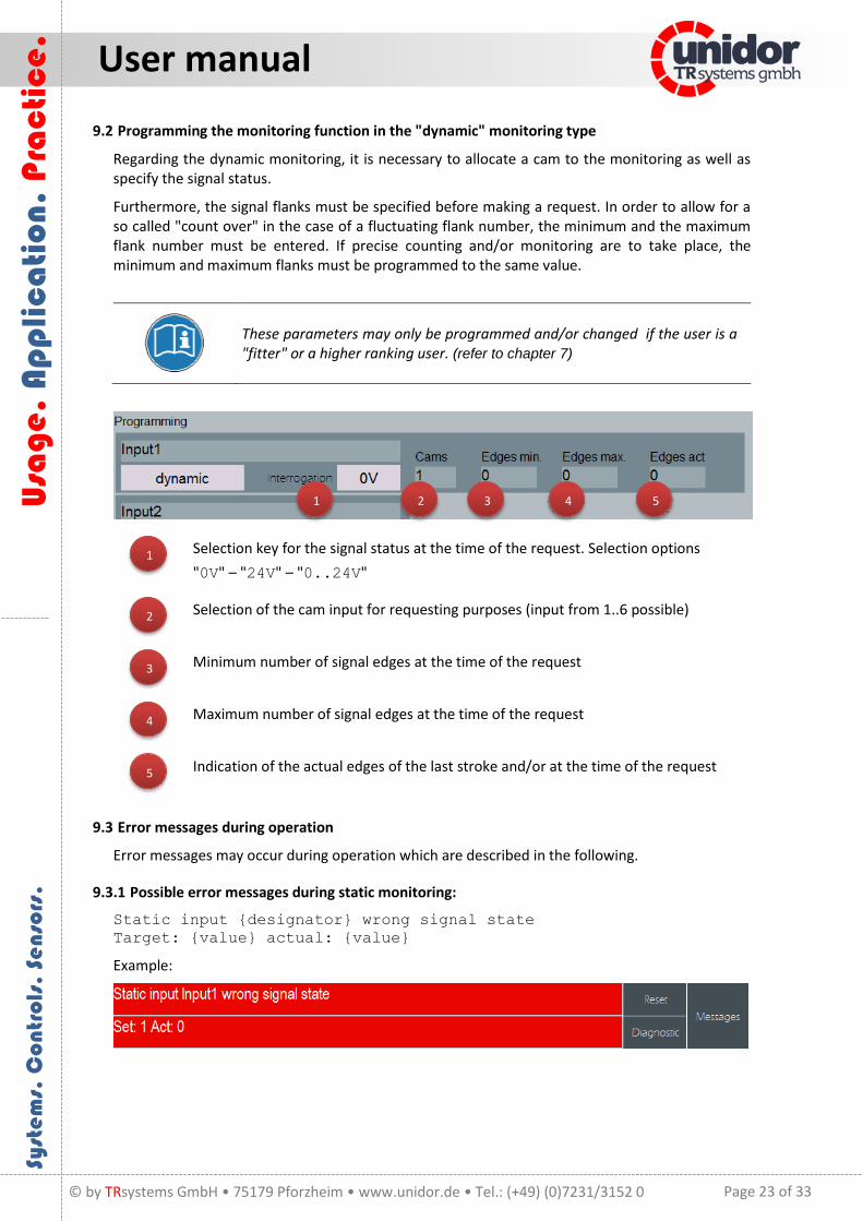
9.2 Programming the monitoring function in the "dynamic" monitoring type
Regarding the dynamic monitoring, it is necessary to allocate a cam to the monitoring as well as specify the signal status.
Furthermore, the signal flanks must be specified before making a request. In order to allow for a so called "count over" in the case of a fluctuating flank number, the minimum and the maximum flank number must be entered. If precise counting and/or monitoring are to take place, the minimum and maximum flanks must be programmed to the same value.
These parameters may only be programmed and/or changed if the user is a "fitter" or a higher ranking user. (refer to chapter 7)
Selection key for the signal status at the time of the request. Selection options
"0V" – "24V" – "0..24V"
Selection of the cam input for requesting purposes (input from 1..6 possible)
Minimum number of signal edges at the time of the request
Maximum number of signal edges at the time of the request
Indication of the actual edges of the last stroke and/or at the time of the request
9.3 Error messages during operation
Error messages may occur during operation which are described in the following.
9.3.1 Possible error messages during static monitoring:
Static input {designator} wrong signal state
Target: {value} actual: {value}
Example:
1
2
3
4
5
1 2 3 4 5

Page 24 of 33
U
sag
e.
Ap
pli
ca
tio
n. P
rac
tic
e.
User manual
Syst
em
s. C
ont
rols
. Se
nso
rs.
© by TRsystems GmbH • 75179 Pforzheim • www.unidor.de • Tel.: (+49) (0)7231/3152 0
9.3.2 Possible error messages during dynamic monitoring:
Dynamic input {designator} not enough changes!
Target: {value} actual: {value}
Example:
Dynamic input {designator} too many changes!
Target: {value} actual: {value}
Example:
{designator} wrong signal state at time of scan!
Target: {value} actual: {value}
Example:
{designator} signal change in scanning cams!
Target: {value} actual: {value}
Example:
9.3.3 Error messages of the cam monitoring function
The system monitors the signal changes of the cams used. If more than one cam is used, they are monitored.
{designator} cam monitoring
Cam {cam number} too few changes!
Example:

Page 25 of 33
U
sag
e.
Ap
pli
ca
tio
n. P
rac
tic
e.
User manual
Syst
em
s. C
ont
rols
. Se
nso
rs.
© by TRsystems GmbH • 75179 Pforzheim • www.unidor.de • Tel.: (+49) (0)7231/3152 0
10 Commissioning function
From the "Maintenance" level, the "commissioning" screen allows for the adjustment of some of the parameters uniform for all dies.
Input field to determine the cam for piece counter as well as stroke rate indication. Admissible input range = 1..6
Input field to determine the maximum number of bridged strokes (internal bridging only). Upon completion of these strokes, the die protection device is automatically activated and/or armed.
Number of teach-in strokes for dynamic inputs.
The "Back" key is used to open the previous page.
1
2
3
4
1
2
3
4

Page 26 of 33
U
sag
e.
Ap
pli
ca
tio
n. P
rac
tic
e.
User manual
Syst
em
s. C
ont
rols
. Se
nso
rs.
© by TRsystems GmbH • 75179 Pforzheim • www.unidor.de • Tel.: (+49) (0)7231/3152 0
11 Counter
The system has 2 piece counters (overall number of pieces + lot size)
The counters may be parameterized via the counter screen. If connected externally, the piece counters may be blocked externally (24 V signal). This may be useful for retrofitting or setting up of the machine since the produced pieces are not counted in this case.
"Strokes per part" and "Parts per stroke" may be programmed.
Once the counter has achieved its target value, the OT stop output is activated (0).
Activate/deactivate counter
Free text designator of the counter
"Set value"/"Actual value" as well as "Strokes/part" and
"Parts/stroke"
Indication of "remaining time" & "finishing time" (only when engaged). The remaining time is calculated which is required for the current stroke rate until the target value of the counter is achieved.
The "Back" key is used to change to the previous page or to the basic screen.
1
2
3
4
5
1 2 3
4 5

Page 27 of 33
U
sag
e.
Ap
pli
ca
tio
n. P
rac
tic
e.
User manual
Syst
em
s. C
ont
rols
. Se
nso
rs.
© by TRsystems GmbH • 75179 Pforzheim • www.unidor.de • Tel.: (+49) (0)7231/3152 0
12 Die administration
The die administration is used to permanently save the settings and programming. An arbitrary* number of dies may be created in the system.
In order to create or activate a die, a user level of "fitter" or higher is required.
The die administration is opened via the "Die" field (1) in the top edge of the screen.
12.1 Basic screen of the die administration
The basic screen of the die administration shows the currently selected die as well as its free text designator (die name).
Current (active) die
With the "Select die" key, an already available die is selected or dies are created or deleted.
With the "Configure die" key, a specified die, for example, is saved.
Data backup options (with available USB memory stick)
*) Depends on free memory
1
2
3
4
1
1
2
4
3

Page 28 of 33
U
sag
e.
Ap
pli
ca
tio
n. P
rac
tic
e.
User manual
Syst
em
s. C
ont
rols
. Se
nso
rs.
© by TRsystems GmbH • 75179 Pforzheim • www.unidor.de • Tel.: (+49) (0)7231/3152 0
12.2 Select die
Once the "Select die" key is pressed, the following screen is displayed.
The screen is divided into different areas. Each area is responsible for a specific function.
In the case of a large number of dies within the die list, the list of all dies already
created may be browsed by entering the die name in the field "Search for die". When opening the screen, the currently active die is selected.
Die information on the die currently selected in the list.
Input field for the new creation of a die.
Copy die selected in the list
Delete die selected in the list
Apply (activate) die selected in the list.
1
2
3
4
5
6
1
2
3 4
5
6

Page 29 of 33
U
sag
e.
Ap
pli
ca
tio
n. P
rac
tic
e.
User manual
Syst
em
s. C
ont
rols
. Se
nso
rs.
© by TRsystems GmbH • 75179 Pforzheim • www.unidor.de • Tel.: (+49) (0)7231/3152 0
12.3 Create new die
In order to create a new die, the input field "New die" (3) must be touched. An on-screen keyboard is then displayed which prompts you to enter the die name.
When a valid die name is entered, the entry must be confirmed with the "Enter key" .
When the "Enter key" is pressed, a dialogue box appears asking if you want to create the new die. Confirm this window by pressing "Yes".
Once confirmed, a clear text designator may be entered.

Page 30 of 33
U
sag
e.
Ap
pli
ca
tio
n. P
rac
tic
e.
User manual
Syst
em
s. C
ont
rols
. Se
nso
rs.
© by TRsystems GmbH • 75179 Pforzheim • www.unidor.de • Tel.: (+49) (0)7231/3152 0
Input of the clear text designator "Die name".
Once confirmed with the "Enter" key, another dialogue field is shown asking if you want to save the die.
When the "Yes" button is pressed, the die is added to the list.
In order to edit the newly created die, it must be activated as the current die. Proceed as described in the following chapter.

Page 31 of 33
U
sag
e.
Ap
pli
ca
tio
n. P
rac
tic
e.
User manual
Syst
em
s. C
ont
rols
. Se
nso
rs.
© by TRsystems GmbH • 75179 Pforzheim • www.unidor.de • Tel.: (+49) (0)7231/3152 0
12.4 Activate/select existing die
In order to activate an already existing die, the desired die must first be selected from the die list. The selected die may be activated by pressing "Accept".
During activating, a window with a progress bar is shown.
Upon completion of the activating procedure, the display changes to the currently active die.
Additionally, a note is displayed in the message line.

Page 32 of 33
U
sag
e.
Ap
pli
ca
tio
n. P
rac
tic
e.
User manual
Syst
em
s. C
ont
rols
. Se
nso
rs.
© by TRsystems GmbH • 75179 Pforzheim • www.unidor.de • Tel.: (+49) (0)7231/3152 0
12.5 Delete available die
To delete the available die, the "Delete die" key is pressed. The display is changed to the deletion view.
In order to delete a die, the die is selected from the list and then deleted by pressing the "Delete" button. A confirmation window is displayed in order to ensure that the correct die is deleted.
If "Yes" is pressed, all die data relating to this die will be deleted.
If "No" is pressed, deletion is cancelled.
Dies may only be deleted if they are not active!

Page 33 of 33
U
sag
e.
Ap
pli
ca
tio
n. P
rac
tic
e.
User manual
Syst
em
s. C
ont
rols
. Se
nso
rs.
© by TRsystems GmbH • 75179 Pforzheim • www.unidor.de • Tel.: (+49) (0)7231/3152 0
13 EC Declaration of Conformity
Manufacturer: TRsystems GmbH, System department Unidor
Factory: Unidor, Freiburger Straße 3, D-75179 Pforzheim
hereby confirm for the
Product: smartDIE-PRO 6
Device type: smartLINE
Model name: smartDIE-PRO 6
compliance with the EC Directive 89/392/EEC and the following standards:
EN 60204.1, Electrical Equipment for Industrial Machines
Electromagnetic Compatibility 89/336/EEC IEC 801 Parts 1, 2, 4
EN 55011 Radio Interference Voltage
EN 55022 Noise Radiation
VDE 0100, VDE 0113, EN 60204
Issued by: TRsystems GmbH, System department Unidor
Date: 6 Oct. 2014
Place: Pforzheim, Germany


![report - Universiti Teknologi Malaysiaeprints.utm.my/id/eprint/2746/1/75179.pdf · Structurally there are five IBS main groups identified as being used in this country [2]. These](https://img.pdfslide.net/doc/110x75/5e355f064537e82f7c4753e7/report-universiti-teknologi-structurally-there-are-five-ibs-main-groups-identified.jpg)