Embed Size (px)
Citation preview
This user manual describes all items concerning the operation of this CNC system in detail. However, it is impossible to give particular descriptions for all unnecessary or unallowable operations due to length limitation and product application conditions;Therefore, the items not presented herein should be considered impractical or unallowable.
Copyright is reserved to GSK CNC Equipment Co., Ltd. It is illegal for any organization or individual to publish or reprint this manual. GSK CNC Equipment Co., Ltd. reserves the right to ascertain their legal liability.
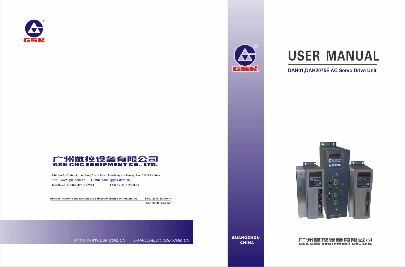
User Manual for DAH01 and DAH2075E AC Servo Drive Unit
II
Dear users,
We are honored by your purchase of all-digital AC servo drive units with high speed and high precision of DAH series of GSK CNC Equipment Co., Ltd.
This manual comprehensively introduces the installation, connection, debugging,
operation and maintenance of the all-digital AC servo drive unit of DAH Series (including DAH01 and DAH2075E) for your easy understanding as well as flexible and efficient application. It provides related knowledge and safety items for the application of the drive unit. Please read the safety notes carefully before using the product.
In order to give full play to the function of the all-digital AC servo drive unit with high precision and high speed of DAH series and ensure your safety, please read the manual carefully before using the product and operate the drive unit correctly in strict accordance with the safety notes and operation methods in the manual.
Improvement, specification and version for the product are subject to change without
notice. If the user modifies the product, our company doest not assume any responsibility,
meanwhile, the warranty certificate is no longer available. This user manual shall be kept by end user.
Sincere appreciation—— Thank you for your kind support when you are using the products of Guangzhou CNC Equipment Co., Ltd.
Preface
Preface
III
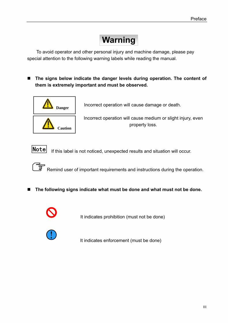
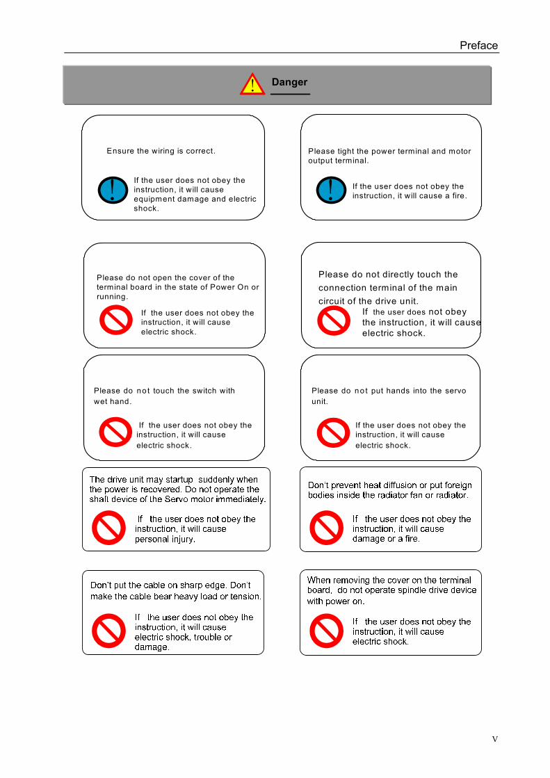
To avoid operator and other personal injury and machine damage, please pay special attention to the following warning labels while reading the manual.
The signs below indicate the danger levels during operation. The content of them is extremely important and must be observed.
Incorrect operation will cause damage or death.
Incorrect operation will cause medium or slight injury, even property loss.
If this label is not noticed, unexpected results and situation will occur.
Remind user of important requirements and instructions during the operation.
The following signs indicate what must be done and what must not be done.
It indicates prohibition (must not be done)
! It indicates enforcement (must be done)
Danger
Caution
Warning
Note
DAH01, DAH2075E AC Servo Drive Unit User Manual
IV
! !
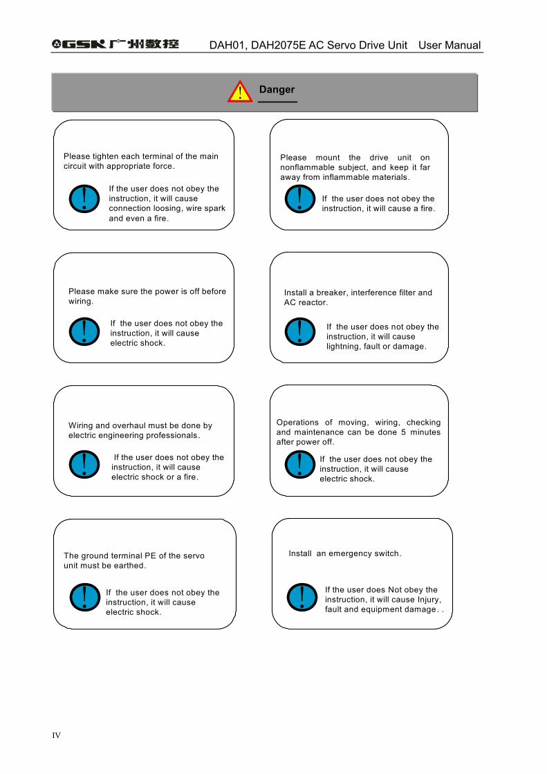
Please tighten each terminal of the main circuit with appropriate force.
If the user does not obey the instruction, it will cause connection loosing, wire spark and even a fire.
Please mount the drive unit on nonflammable subject, and keep it far away from inflammable materials.
If the user does not obey the instruction, it will cause a fire.
! !
Please make sure the power is off before wiring.
If the user does not obey the instruction, it will cause electric shock.
Install a breaker, interference filter and AC reactor.
If the user does not obey the instruction, it will cause lightning, fault or damage.
! !
Wiring and overhaul must be done by electric engineering professionals.
If the user does not obey the instruction, it will cause electric shock or a fire.
Operations of moving, wiring, checking and maintenance can be done 5 minutes after power off.
If the user does not obey the instruction, it will cause electric shock.
! !
The ground terminal PE of the servo unit must be earthed.
If the user does not obey the instruction, it will cause electric shock.
Install an emergency switch.
If the user does Not obey the instruction, it will cause Injury, fault and equipment damage. .
! Danger
Preface
V
! !
Please tight the power terminal and motor output terminal.
If the user does not obey the instruction, it will cause a fire.
Ensure the wiring is correct.
If the user does not obey the instruction, it will cause equipment damage and electric shock.
Please do not open the cover of the terminal board in the state of Power On or running.
If the user does not obey the instruction, it will cause electric shock.
Please do not directly touch the connection terminal of the main circuit of the drive unit.
If the user does not obey the instruction, it will cause electric shock.
Please do no t touch the switch with wet hand.
If the user does not obey the instruction, it will cause electric shock.
Please do no t put hands into the servo unit.
If the user does not obey the instruction, it will cause electric shock.
! Danger
DAH01, DAH2075E AC Servo Drive Unit User Manual
VI
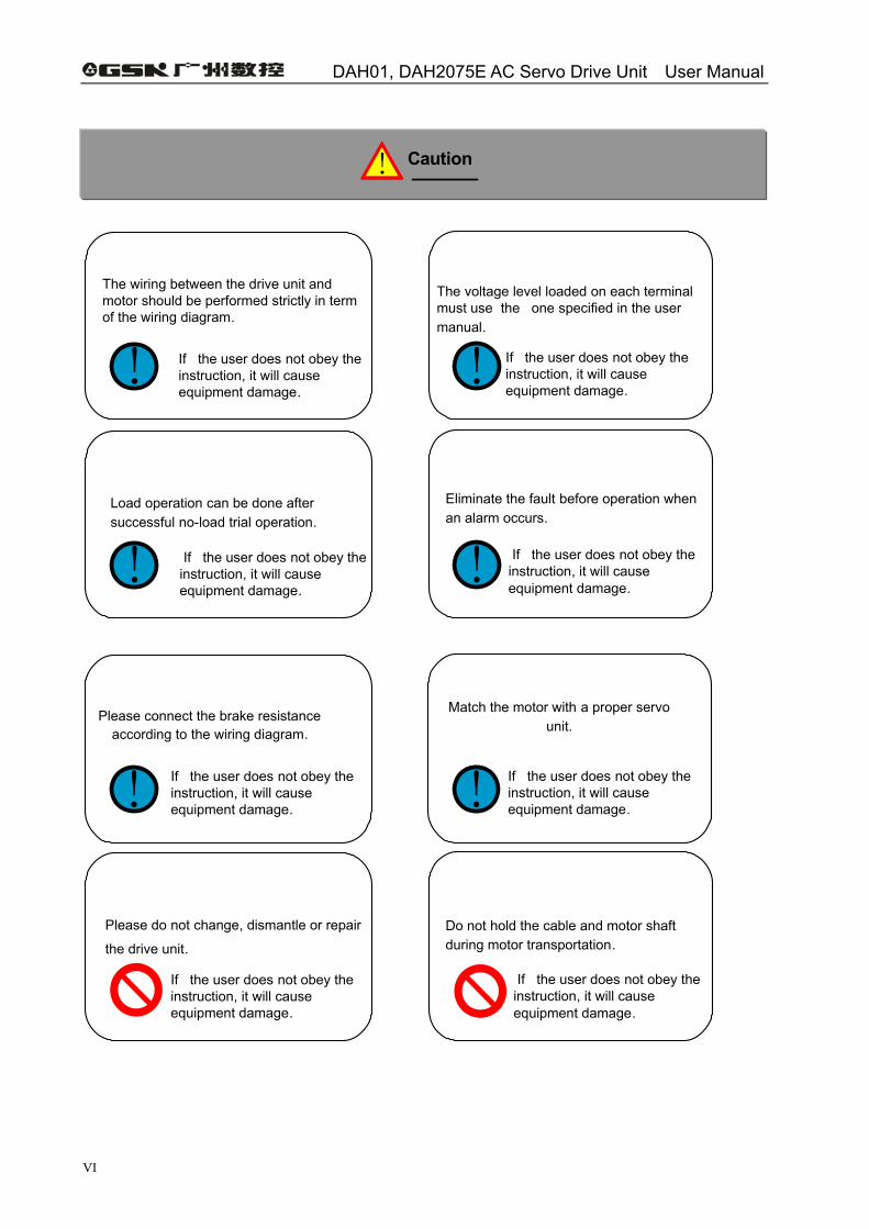
! !
The voltage level loaded on each terminal must use the one specified in the user manual.
If the user does not obey the instruction, it will cause equipment damage.
The wiring between the drive unit and motor should be performed strictly in term of the wiring diagram.
If the user does not obey the instruction, it will cause equipment damage.
! !
Load operation can be done after successful no-load trial operation.
If the user does not obey the instruction, it will cause equipment damage.
Eliminate the fault before operation when an alarm occurs.
If the user does not obey the instruction, it will cause equipment damage.
! !
Match the motor with a proper servo unit.
If the user does not obey the instruction, it will cause equipment damage.
Please connect the brake resistance according to the wiring diagram.
If the user does not obey the instruction, it will cause equipment damage.
Please do not change, dismantle or repair
the drive unit.
If the user does not obey the instruction, it will cause equipment damage.
Do not hold the cable and motor shaft during motor transportation.
If the user does not obey the instruction, it will cause equipment damage.
! Caution
Preface
VII
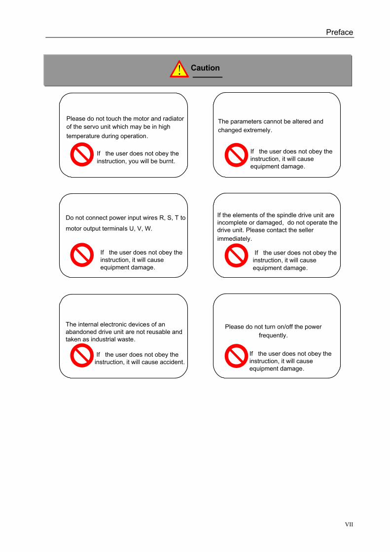
Please do not touch the motor and radiator of the servo unit which may be in high temperature during operation.
If the user does not obey the instruction, you will be burnt.
The parameters cannot be altered and changed extremely.
If the user does not obey the instruction, it will cause equipment damage.
If the elements of the spindle drive unit are incomplete or damaged, do not operate the drive unit. Please contact the seller immediately.
If the user does not obey the instruction, it will cause equipment damage.
Do not connect power input wires R, S, T to
motor output terminals U, V, W.
If the user does not obey the instruction, it will cause equipment damage.
The internal electronic devices of an abandoned drive unit are not reusable and taken as industrial waste.
If the user does not obey the instruction, it will cause accident.
Please do not turn on/off the power frequently.
If the user does not obey the instruction, it will cause equipment damage.
! Caution
DAH01, DAH2075E AC Servo Drive Unit User Manual
VIII
Safety Responsibility
Manufacturer Responsibility
——Be responsible for the danger which has been eliminated and/or controlled on design and configuration of the provided servo unit and accessories. ——Be responsible for the safety of the provided servo unit and accessories. ——Be responsible for the provided information and advice for the users.
User Responsibility ——Be trained with the safety operation of the servo unit and familiar with the safety
operation procedures. ——Be responsible for the dangers caused by adding, changing or altering the original
servo unit and the accessories. ——Be responsible for the danger without following the operations, maintenances,
installations and storages described in the manual.
Contents
IX
Contents CHAPTER 1 OVERVIEW ··························································································1
1.1 Product Introduction ·························································································1 1.2 Confirmation of the Arrived Goods ···································································4 1.3 Product Appearance·························································································8
CHAPTER 2 INSTALLATION···················································································10 2.1 Ambient Conditions ························································································10 2.2 Installation for Servo Drive Unit ······································································10 2.3 Installation for Servo Motor ············································································15
CHAPTER 3 CONNECTION····················································································16 3.1 Standard Wiring······························································································16 3.2 Terminal Function ···························································································21 3.3 GSK-LINK Bus Communication Principle ·······················································30 3.4 I/O Interface Principle·····················································································30
CHAPTER 4 PARAMETER······················································································35 4.1 Parameter List································································································35 4.2 Specification for Parameter Meaning ·····························································38 4.3 Comparison Table of Type Code Parameters and Spindle Motors ·················48
CHAPTER 5 ALARM AND TROUBLSHOOTING·····················································50 5.1 Alarm List ·······································································································50 5.2 Alarm Troubleshooting····················································································51
CHAPTER 6 DISPLAY AND OPERATION·······························································58 6.1 Keyboard Operation ·······················································································58 6.2 Monitoring Mode·····························································································59 6.3 Parameter Setting ··························································································61 6.4 Parameter Management·················································································61 6.5 Speed Trial Run······························································································63 6.6 JOG Operation ·······························································································64 6.7 Motor Test·······································································································64 6.8 User Shortcut Password·················································································64 6.9 Servo Parameter Auto Setting ········································································65 6.10 Others ··········································································································65
CHAPTER 7 RUN····································································································66 7.1 Power Supply Connection ··············································································66 7.2 Trial Run·········································································································68 7.3 Adjustment ·····································································································70
CHAPTER 8 PRODUCT SPECIFICATION······························································72 8.1 Specifications of Drive Unit·············································································72

DAH01, DAH2075E AC Servo Drive Unit User Manual
X
8.2 Servo Motor Specification·············································································· 74 8.3 Isolation Transformer····················································································· 78
Chapter 9 ORDER INSTRUCTION········································································· 82 9.1 Capacity Selection························································································· 82 9.2 Electronic gear ratio······················································································· 84 9.3 Stop characteristcs ························································································ 85 9.4 Calculation methods of servo drive unit and position controller selection······ 85
Chapter 1 Overview
1
CHAPTER 1 OVERVIEW
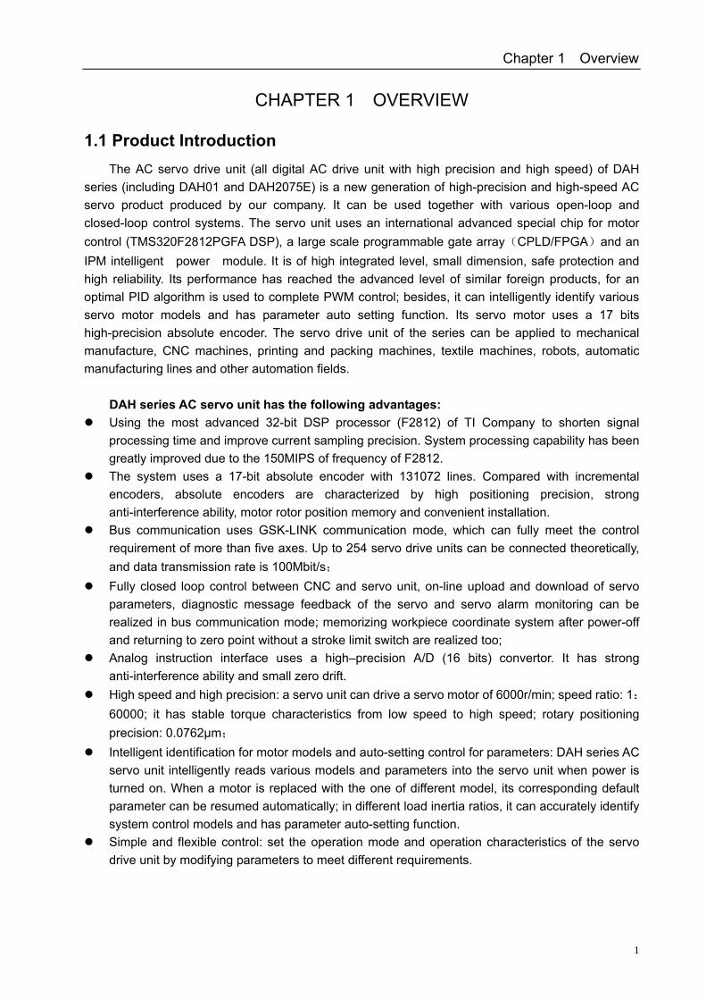
1.1 Product Introduction The AC servo drive unit (all digital AC drive unit with high precision and high speed) of DAH
series (including DAH01 and DAH2075E) is a new generation of high-precision and high-speed AC servo product produced by our company. It can be used together with various open-loop and closed-loop control systems. The servo unit uses an international advanced special chip for motor control (TMS320F2812PGFA DSP), a large scale programmable gate array(CPLD/FPGA)and an IPM intelligent power module. It is of high integrated level, small dimension, safe protection and high reliability. Its performance has reached the advanced level of similar foreign products, for an optimal PID algorithm is used to complete PWM control; besides, it can intelligently identify various servo motor models and has parameter auto setting function. Its servo motor uses a 17 bits high-precision absolute encoder. The servo drive unit of the series can be applied to mechanical manufacture, CNC machines, printing and packing machines, textile machines, robots, automatic manufacturing lines and other automation fields.
DAH series AC servo unit has the following advantages:
Using the most advanced 32-bit DSP processor (F2812) of TI Company to shorten signal processing time and improve current sampling precision. System processing capability has been greatly improved due to the 150MIPS of frequency of F2812.
The system uses a 17-bit absolute encoder with 131072 lines. Compared with incremental encoders, absolute encoders are characterized by high positioning precision, strong anti-interference ability, motor rotor position memory and convenient installation.
Bus communication uses GSK-LINK communication mode, which can fully meet the control requirement of more than five axes. Up to 254 servo drive units can be connected theoretically, and data transmission rate is 100Mbit/s;
Fully closed loop control between CNC and servo unit, on-line upload and download of servo parameters, diagnostic message feedback of the servo and servo alarm monitoring can be realized in bus communication mode; memorizing workpiece coordinate system after power-off and returning to zero point without a stroke limit switch are realized too;
Analog instruction interface uses a high–precision A/D (16 bits) convertor. It has strong anti-interference ability and small zero drift.
High speed and high precision: a servo unit can drive a servo motor of 6000r/min; speed ratio: 1:60000; it has stable torque characteristics from low speed to high speed; rotary positioning precision: 0.0762μm;
Intelligent identification for motor models and auto-setting control for parameters: DAH series AC servo unit intelligently reads various models and parameters into the servo unit when power is turned on. When a motor is replaced with the one of different model, its corresponding default parameter can be resumed automatically; in different load inertia ratios, it can accurately identify system control models and has parameter auto-setting function.
Simple and flexible control: set the operation mode and operation characteristics of the servo drive unit by modifying parameters to meet different requirements.
DAH01, DAH2075E AC Servo Drive Unit User Manual
2
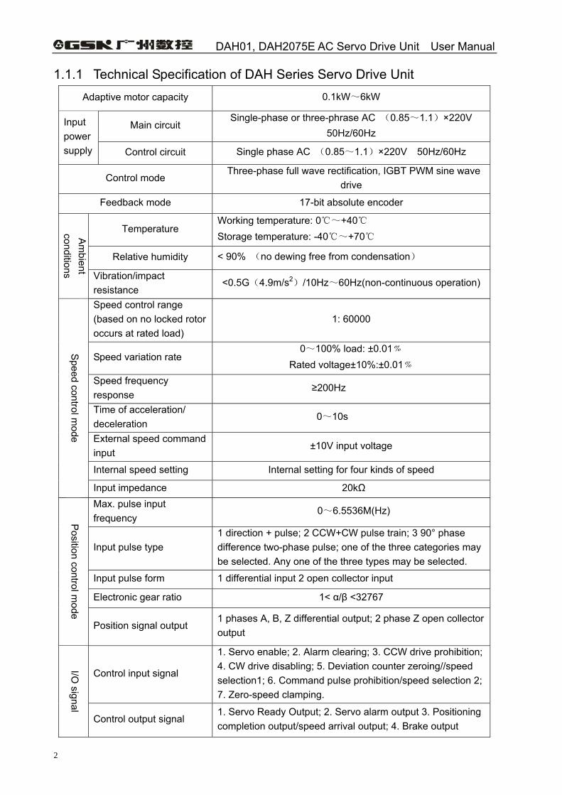
1.1.1 Technical Specification of DAH Series Servo Drive Unit Adaptive motor capacity 0.1kW~6kW
Main circuit Single-phase or three-phrase AC (0.85~1.1)×220V
50Hz/60Hz Input power supply Control circuit Single phase AC (0.85~1.1)×220V 50Hz/60Hz
Control mode Three-phase full wave rectification, IGBT PWM sine wave
drive
Feedback mode 17-bit absolute encoder
Temperature Working temperature: 0~+40 Storage temperature: -40~+70
Relative humidity < 90% (no dewing free from condensation)
Am
bient conditions Vibration/impact
resistance <0.5G(4.9m/s2)/10Hz~60Hz(non-continuous operation)
Speed control range (based on no locked rotor occurs at rated load)
1: 60000
Speed variation rate 0~100% load: ±0.01﹪
Rated voltage±10%:±0.01﹪ Speed frequency response
≥200Hz
Time of acceleration/ deceleration
0~10s
External speed command input
±10V input voltage
Internal speed setting Internal setting for four kinds of speed
Speed control m
ode Input impedance 20kΩ Max. pulse input frequency
0~6.5536M(Hz)
Input pulse type 1 direction + pulse; 2 CCW+CW pulse train; 3 90° phase difference two-phase pulse; one of the three categories may be selected. Any one of the three types may be selected.
Input pulse form 1 differential input 2 open collector input
Electronic gear ratio 1< α/β <32767
Position control m
ode
Position signal output 1 phases A, B, Z differential output; 2 phase Z open collector output
Control input signal
1. Servo enable; 2. Alarm clearing; 3. CCW drive prohibition; 4. CW drive disabling; 5. Deviation counter zeroing//speed selection1; 6. Command pulse prohibition/speed selection 2; 7. Zero-speed clamping.
I/O signal
Control output signal 1. Servo Ready Output; 2. Servo alarm output 3. Positioning completion output/speed arrival output; 4. Brake output
Chapter 1 Overview
3
Internal
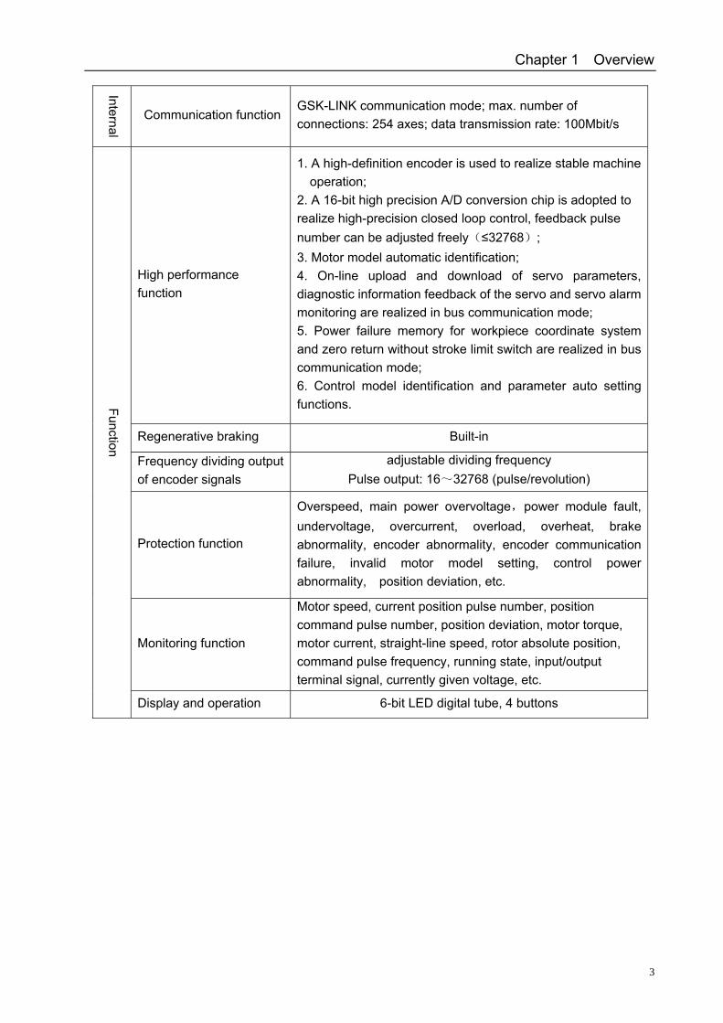
Communication function GSK-LINK communication mode; max. number of connections: 254 axes; data transmission rate: 100Mbit/s
High performance function
1. A high-definition encoder is used to realize stable machine operation;
2. A 16-bit high precision A/D conversion chip is adopted to realize high-precision closed loop control, feedback pulse number can be adjusted freely(≤32768); 3. Motor model automatic identification; 4. On-line upload and download of servo parameters, diagnostic information feedback of the servo and servo alarm monitoring are realized in bus communication mode; 5. Power failure memory for workpiece coordinate system and zero return without stroke limit switch are realized in bus communication mode; 6. Control model identification and parameter auto setting functions.
Regenerative braking Built-in
Frequency dividing output of encoder signals
adjustable dividing frequency Pulse output: 16~32768 (pulse/revolution)
Protection function
Overspeed, main power overvoltage,power module fault, undervoltage, overcurrent, overload, overheat, brake abnormality, encoder abnormality, encoder communication failure, invalid motor model setting, control power abnormality, position deviation, etc.
Monitoring function
Motor speed, current position pulse number, position command pulse number, position deviation, motor torque, motor current, straight-line speed, rotor absolute position, command pulse frequency, running state, input/output terminal signal, currently given voltage, etc.
Function
Display and operation 6-bit LED digital tube, 4 buttons
DAH01, DAH2075E AC Servo Drive Unit User Manual
4
1.2 Confirmation of the Arrived Goods 1) Please check the received goods in accordance with the following items:
(1) Check whether the packing box is in good condition and the products are damaged in delivery. (2) Confirm whether the products are the ordered ones according to the nameplates of the servo drive units and servo motors. (3) Confirm whether the accessories in the packing box are complete in terms of the packing list.
An AC servo unit should be used together with its adaptive servo motor.
Any questions, please feel free to contact suppliers or our company.
Note A damaged or incomplete AC servo unit can not be installed.
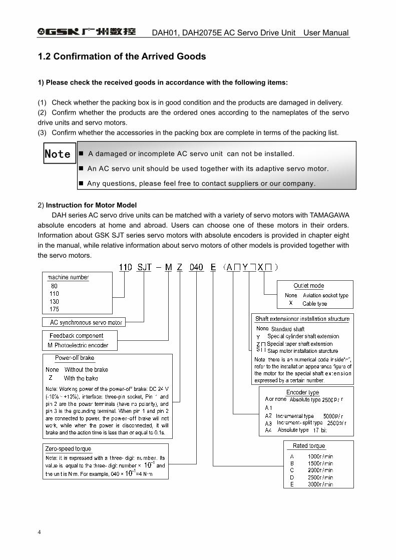
2) Instruction for Motor Model DAH series AC servo drive units can be matched with a variety of servo motors with TAMAGAWA absolute encoders at home and abroad. Users can choose one of these motors in their orders. Information about GSK SJT series servo motors with absolute encoders is provided in chapter eight in the manual, while relative information about servo motors of other models is provided together with the servo motors.
Chapter 1 Overview
5
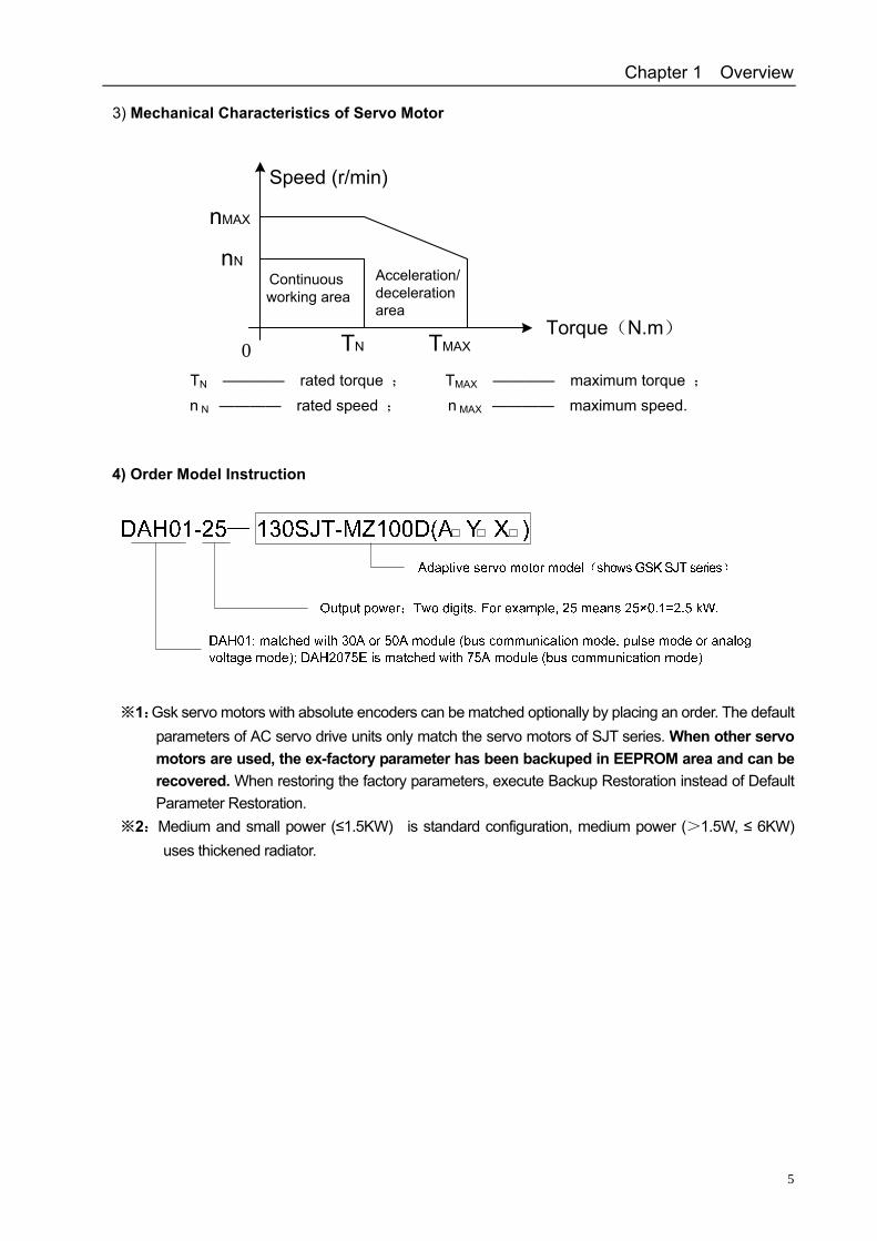
3) Mechanical Characteristics of Servo Motor
Acceleration/deceleration area
Torque(N.m)
Continuousworking area
0
Speed (r/min)
nMAX
nN
TN TMAX
TN ———— rated torque ; TMAX ———— maximum torque ; n N ———— rated speed ; n MAX ———— maximum speed.
4) Order Model Instruction
1※ :Gsk servo motors with absolute encoders can be matched optionally by placing an order. The default parameters of AC servo drive units only match the servo motors of SJT series. When other servo motors are used, the ex-factory parameter has been backuped in EEPROM area and can be recovered. When restoring the factory parameters, execute Backup Restoration instead of Default Parameter Restoration.
2※ :Medium and small power (≤1.5KW) is standard configuration, medium power (>1.5W, ≤ 6KW) uses thickened radiator.
DAH01, DAH2075E AC Servo Drive Unit User Manual
6
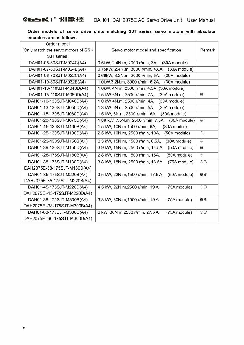
Order models of servo drive units matching SJT series servo motors with absolute encoders are as follows:
Order model (Only match the servo motors of GSK
SJT series) Servo motor model and specification Remark
DAH01-05-80SJT-M024C(A4) 0.5kW, 2.4N.m, 2000 r/min, 3A, (30A module) DAH01-07-80SJT-M024E(A4) 0.75kW, 2.4N.m, 3000 r/min, 4.8A, (30A module) DAH01-06-80SJT-M032C(A4) 0.66kW, 3.2N.m ,2000 r/min, 5A, (30A module) DAH01-10-80SJT-M032E(A4) 1.0kW,3.2N.m, 3000 r/min, 6.2A, (30A module) DAH01-10-110SJT-M040D(A4) 1.0kW, 4N.m, 2500 r/min, 4.5A, (30A module) DAH01-15-110SJT-M060D(A4) 1.5 kW 6N.m, 2500 r/min, 7A, (30A module) ※ DAH01-10-130SJT-M040D(A4) 1.0 kW 4N.m, 2500 r/min, 4A, (30A module) DAH01-13-130SJT-M050D(A4) 1.3 kW 5N.m, 2500 r/min, 5A, (30A module) DAH01-15-130SJT-M060D(A4) 1.5 kW, 6N.m, 2500 r/min , 6A, (30A module) DAH01-20-130SJT-M075D(A4) 1.88 kW, 7.5N.m, 2500 r/min, 7.5A, (30A module) ※ DAH01-15-130SJT-M100B(A4) 1.5 kW, 10N.m 1500 r/min, 6A, (30A module) DAH01-25-130SJT-M100D(A4) 2.5 kW, 10N.m, 2500 r/min, 10A, (50A module) ※
DAH01-23-130SJT-M150B(A4) 2.3 kW, 15N.m, 1500 r/min, 8.5A, (30A module) ※ DAH01-39-130SJT-M150D(A4) 3.9 kW, 15N.m, 2500 r/min, 14.5A, (50A module) ※
DAH01-28-175SJT-M180B(A4) 2.8 kW, 18N.m, 1500 r/min, 15A, (50A module) ※ DAH01-38-175SJT-M180D(A4)
DAH2075E-38-175SJT-M180D(A4) 3.8 kW, 18N.m, 2500 r/min, 16.5A, (75A module) ※※
DAH01-35-175SJT-M220B(A4) DAH2075E-35-175SJT-M220B(A4)
3.5 kW, 22N.m,1500 r/min, 17.5 A, (50A module) ※※
DAH01-45-175SJT-M220D(A4) DAH2075E -45-175SJT-M220D(A4)
4.5 kW, 22N.m,2500 r/min, 19 A, (75A module) ※※
DAH01-38-175SJT-M300B(A4) DAH2075E -38-175SJT-M300B(A4)
3.8 kW, 30N.m,1500 r/min, 19 A, (75A module) ※※
DAH01-60-175SJT-M300D(A4) DAH2075E -60-175SJT-M300D(A4)
6 kW, 30N.m,2500 r/min, 27.5 A, (75A module) ※※
Chapter 1 Overview
7
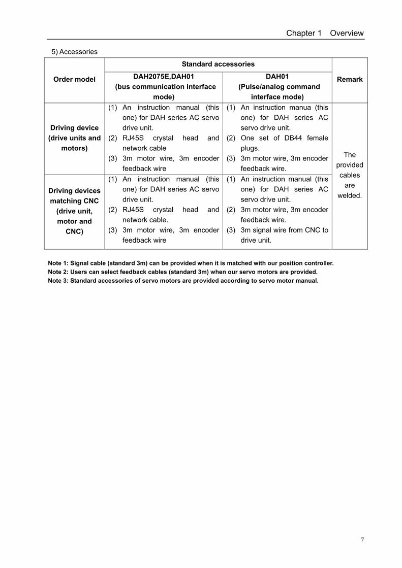
5) Accessories
Standard accessories
Order model DAH2075E,DAH01 (bus communication interface
mode)
DAH01 (Pulse/analog command
interface mode)
Remark
Driving device (drive units and
motors)
(1) An instruction manual (this one) for DAH series AC servo drive unit.
(2) RJ45S crystal head and network cable
(3) 3m motor wire, 3m encoder feedback wire
(1) An instruction manua (this one) for DAH series AC servo drive unit.
(2) One set of DB44 female plugs.
(3) 3m motor wire, 3m encoder feedback wire.
Driving devices matching CNC
(drive unit, motor and
CNC)
(1) An instruction manual (this one) for DAH series AC servo drive unit.
(2) RJ45S crystal head and network cable.
(3) 3m motor wire, 3m encoder feedback wire
(1) An instruction manual (this one) for DAH series AC servo drive unit.
(2) 3m motor wire, 3m encoder feedback wire.
(3) 3m signal wire from CNC to drive unit.
The provided cables
are welded.
Note 1: Signal cable (standard 3m) can be provided when it is matched with our position controller. Note 2: Users can select feedback cables (standard 3m) when our servo motors are provided. Note 3: Standard accessories of servo motors are provided according to servo motor manual.
DAH01, DAH2075E AC Servo Drive Unit User Manual
8
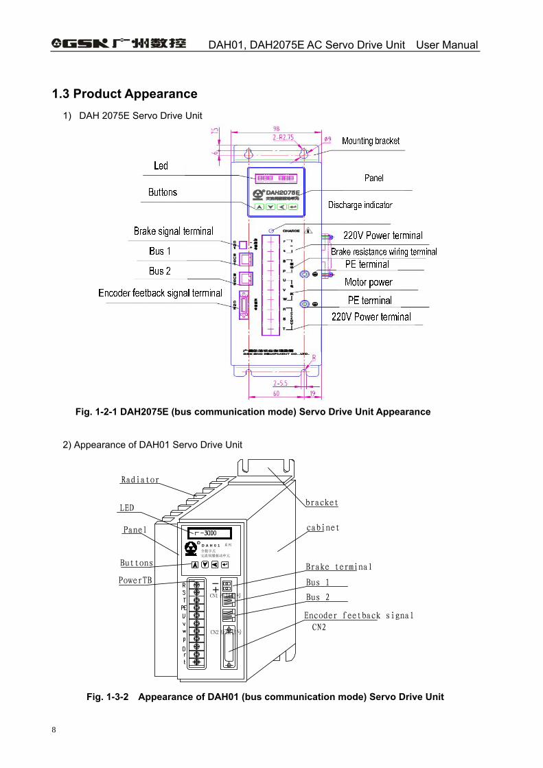
1.3 Product Appearance 1) DAH 2075E Servo Drive Unit
Fig. 1-2-1 DAH2075E (bus communication mode) Servo Drive Unit Appearance
2) Appearance of DAH01 Servo Drive Unit
Fig. 1-3-2 Appearance of DAH01 (bus communication mode) Servo Drive Unit
Brake terminal
Bus 2
交流伺服驱动单元
全数字式
R
bracket
cabinet
系列
Radiator
LED
Panel
D A H 0 1
Bus 1
Encoder feetback signal CN2
Buttons
PowerTB
CN1 控制信号
CN2 反馈信号
+ -
Chapter 1 Overview
9
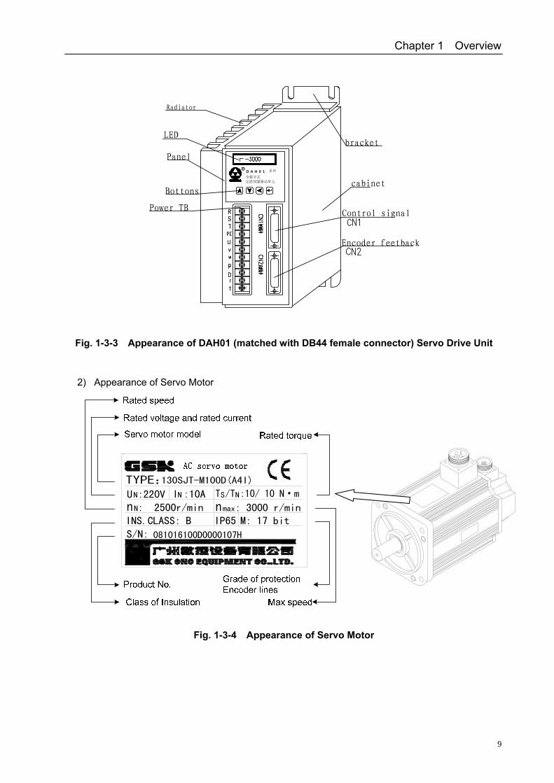
Fig. 1-3-3 Appearance of DAH01 (matched with DB44 female connector) Servo Drive Unit
2) Appearance of Servo Motor
Fig. 1-3-4 Appearance of Servo Motor
Power TB
Bottons
Encoder feetback
Control signal
Panel
LED
Radiator
cabinet
bracket
交流伺服驱动单元全数字式
R系列D A H 0 1
S/N:
max
NS
交流伺服电动机
N
NN
M: 17 bit: 3000 r/min
I :10A : 2500r/min
081016100D0000107H
IP65INS.CLASS: B
U :220V
DAH01, DAH2075E AC Servo Drive Unit User Manual
10
CHAPTER 2 INSTALLATION
Note
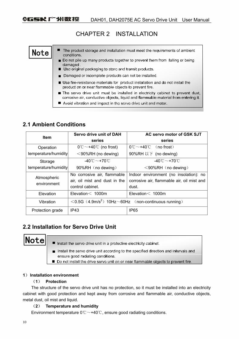
2.1 Ambient Conditions
Item Servo drive unit of DAH
series AC servo motor of GSK SJT
series Operation
temperature/humidity 0~+40 (no frost) <90%RH (no dewing)
0~+40 (no frost) 90%RH 以下 (no dewing)
Storage temperature/humidity
-40~+70 90%RH(no dewing)
-40~+70 <90%RH(no dewing)
Atmospheric environment
No corrosive air, flammable air, oil mist and dust in the control cabinet.
Indoor environment (no insolation): no corrosive air, flammable air, oil mist and dust.
Elevation Elevation< 1000m Elevation< 1000m
Vibration <0.5G(4.9m/s2)10Hz~60Hz (non-continuous running)
Protection grade IP43 IP65
2.2 Installation for Servo Drive Unit
Note
1) Installation environment
(1) Protection The structure of the servo drive unit has no protection, so it must be installed into an electricity
cabinet with good protection and kept away from corrosive and flammable air, conductive objects, metal dust, oil mist and liquid.
(2) Temperature and humidity Environment temperature 0~+40 , ensure good radiating conditions.
Chapter 2 Installation
11
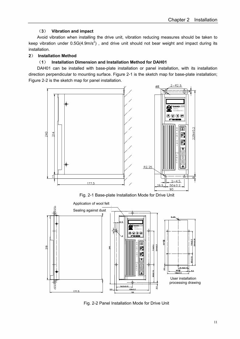
(3) Vibration and impact Avoid vibration when installing the drive unit, vibration reducing measures should be taken to
keep vibration under 0.5G(4.9m/s2) , and drive unit should not bear weight and impact during its installation. 2) Installation Method
(1) Installation Dimension and Installation Method for DAH01 DAH01 can be installed with base-plate installation or panel installation, with its installation
direction perpendicular to mounting surface. Figure 2-1 is the sketch map for base-plate installation; Figure 2-2 is the sketch map for panel installation.
交流伺服驱动单元
全数字式
R
图2-1 驱动单元底板安装方式
总
线
CN2
反
馈
信
号
2
1
总
线
抱
闸
DAH01
用户安装加工图
图2-2 驱动单元面板安装方式
抱
闸
总
线1
2
总
线
CN2
反
馈
信
号
全数字式
交流伺服驱动单元
DAH01R
密封防尘
贴羊毛毡
Fig. 2-1 Base-plate Installation Mode for Drive Unit
Fig. 2-2 Panel Installation Mode for Drive Unit
User installation processing drawing
Application of wool felt
Sealing against dust
DAH01, DAH2075E AC Servo Drive Unit User Manual
12
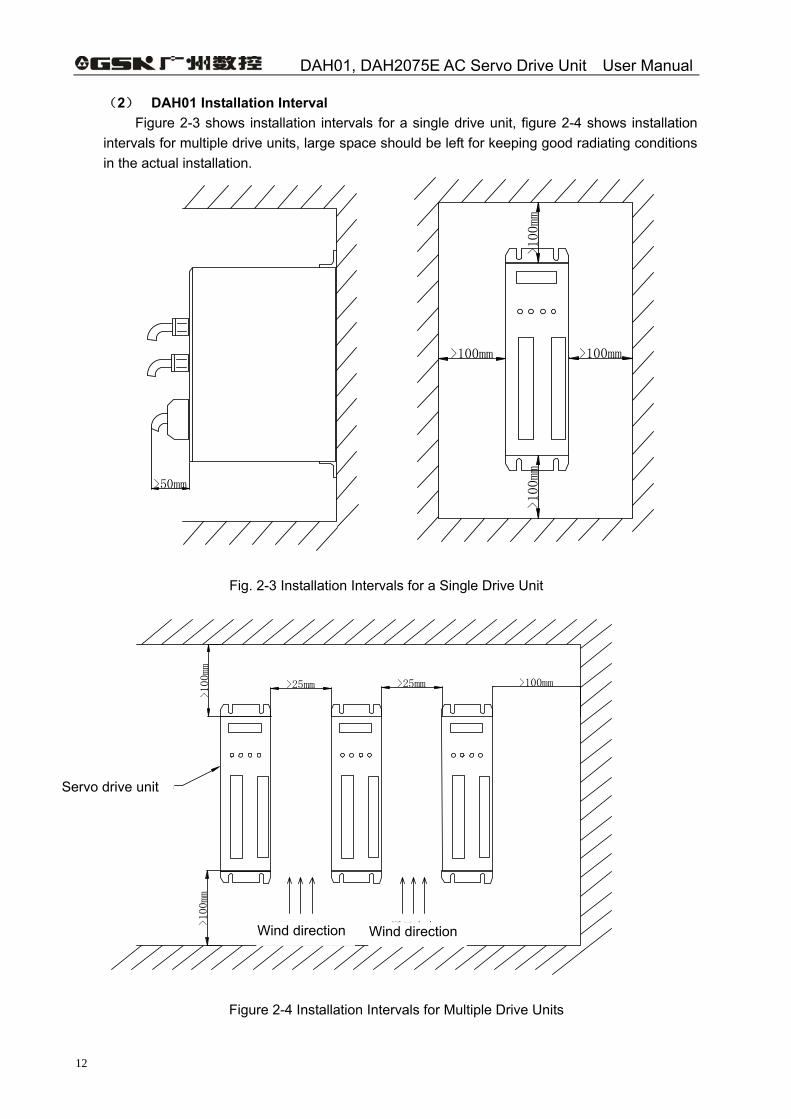
(2) DAH01 Installation Interval Figure 2-3 shows installation intervals for a single drive unit, figure 2-4 shows installation
intervals for multiple drive units, large space should be left for keeping good radiating conditions in the actual installation.
>100mm
>100mm
>100mm>100mm
>50mm
Fig. 2-3 Installation Intervals for a Single Drive Unit
伺服驱动单元
通风方向通风方向>100mm
>100mm
>100mm>25mm>25mm
Figure 2-4 Installation Intervals for Multiple Drive Units
Servo drive unit
Wind direction Wind direction
Chapter 2 Installation
13
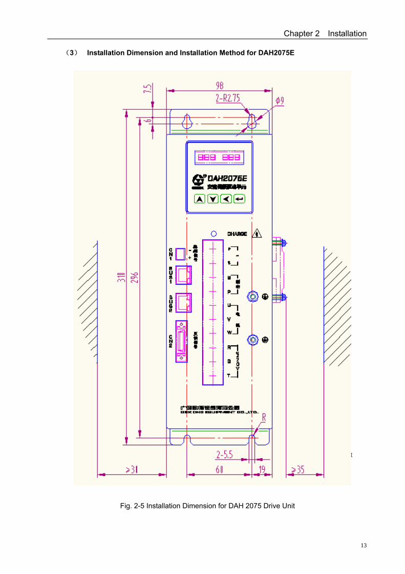
(3) Installation Dimension and Installation Method for DAH2075E
Fig. 2-5 Installation Dimension for DAH 2075 Drive Unit
Fig. 2-5 Base-plate Installation Dimension and Intervals (Front) for DAH 2075 Drive Unit
DAH01, DAH2075E AC Servo Drive Unit User Manual
14
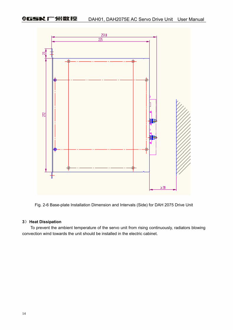
Fig. 2-6 Base-plate Installation Dimension and Intervals (Side) for DAH 2075 Drive Unit 3) Heat Dissipation
To prevent the ambient temperature of the servo unit from rising continuously, radiators blowing convection wind towards the unit should be installed in the electric cabinet.
Chapter 2 Installation
15
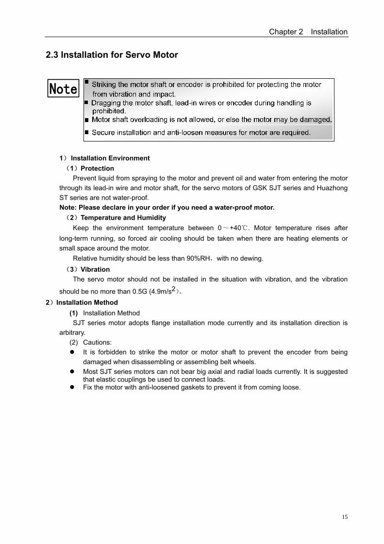
2.3 Installation for Servo Motor
Note
1) Installation Environment (1) Protection
Prevent liquid from spraying to the motor and prevent oil and water from entering the motor through its lead-in wire and motor shaft, for the servo motors of GSK SJT series and Huazhong ST series are not water-proof. Note: Please declare in your order if you need a water-proof motor. (2) Temperature and Humidity
Keep the environment temperature between 0~+40 . Motor temperature rise s after long-term running, so forced air cooling should be taken when there are heating elements or small space around the motor.
Relative humidity should be less than 90%RH,with no dewing. (3) Vibration
The servo motor should not be installed in the situation with vibration, and the vibration
should be no more than 0.5G (4.9m/s2)。 2)Installation Method
(1) Installation Method SJT series motor adopts flange installation mode currently and its installation direction is
arbitrary. (2) Cautions:
It is forbidden to strike the motor or motor shaft to prevent the encoder from being damaged when disassembling or assembling belt wheels.
Most SJT series motors can not bear big axial and radial loads currently. It is suggested that elastic couplings be used to connect loads.
Fix the motor with anti-loosened gaskets to prevent it from coming loose.
DAH01, DAH2075E AC Servo Drive Unit User Manual
16
CHAPTER 3 CONNECTION
! Caution
3.1 Standard Wiring
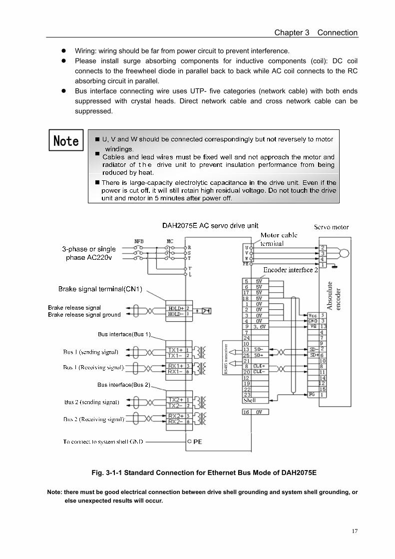
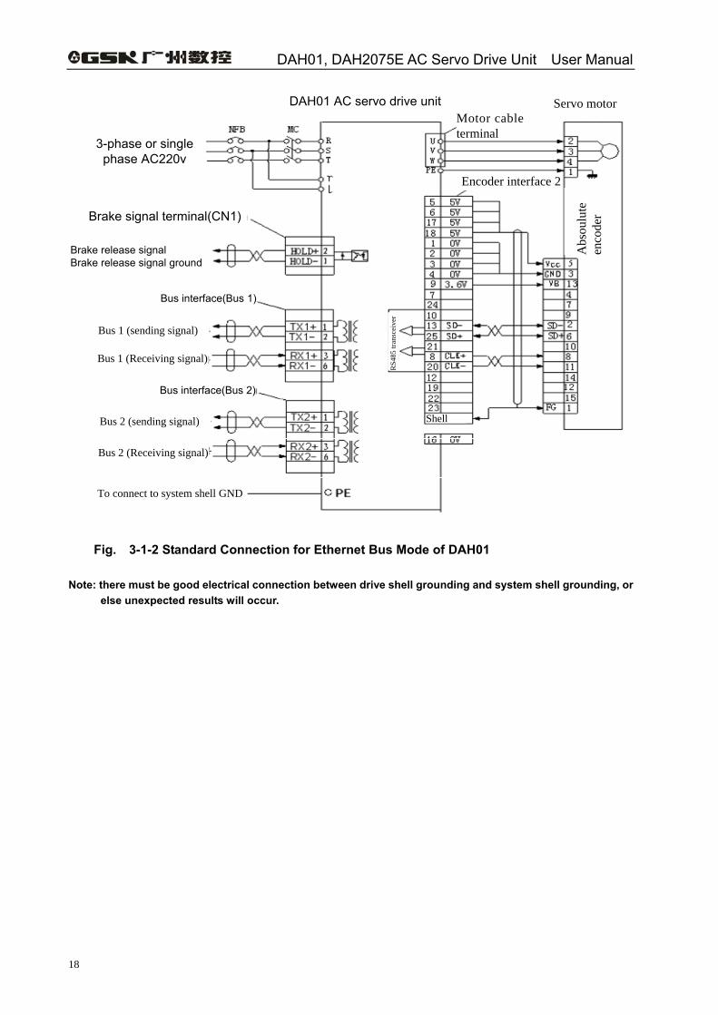
1) Ethernet Bus Mode Figure 3-1-1 and figure 3-1-2 show the Ethernet bus standard wiring for DAH01 and
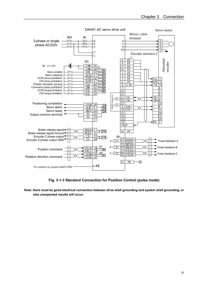
DAH2075E respectively. 2) Position Control Mode (Pulse Mode)
Figure 3-1-3 shows the standard wiring for position control (pulse mode). 3) Speed Control Mode (Analog Voltage Mode)
Figure 3-1-4 shows the standard wiring for speed control (analog voltage mode). 4) Wiring
(1) Power Terminal TB
Wire cross-sectional area: For terminals R、S、T、PE、U、V and W, cross-sectional
area≥1.5mm2(AWG14~16); for terminals r and t, cross-sectional area ≥1.0 mm2(AWG16~18). Grounding: grounding wires should be as thick as possible. Drive unit shell, servo motor and system shell are earthed at one point of PE terminal. Earthing resistance <0.1Ω. Terminal connection adopts SVM2-4 pre-insulated cold-press terminals which must be connected securely. It is suggested that the power be supplied through a three-phase isolation transformer to reduce the possibility of electric shock. It is suggested that the power supply through connecting a noise filter to improve anti-interference capability. Please install a non-fuse breaker (NFB) to cut off the power in time when a fault occurs in the drive unit.
Control Signal CN1 and Feedback Signal CN2
Wire selection: use screen cables (twisted ones are recommended ), Cross-sectional area
≥0.12mm2(AWG24~26),shield layer must be connected to FG terminal. Wire length: wires should be as short as possible, the wire for controlling CN1 should not be
longer than 3m, and feedback signal for controlling CN2 should not be longer than 20m.
Only qualified persons can connect the system or check the connection
Wiring and checking cannot be done in 5 minutes after the power supply is switched off to avoid electric shock.
Wiring must be performed in terms of the terminal voltage and polarity to avoid equipment damage and personnel injury.
The drive unit and servo motor must be grounded well.
Chapter 3 Connection
17
Wiring: wiring should be far from power circuit to prevent interference. Please install surge absorbing components for inductive components (coil): DC coil
connects to the freewheel diode in parallel back to back while AC coil connects to the RC absorbing circuit in parallel.
Bus interface connecting wire uses UTP- five categories (network cable) with both ends suppressed with crystal heads. Direct network cable and cross network cable can be suppressed.
Note
Abs
oulu
te
enco
der
RS4
85 tr
ansc
eive
r
Fig. 3-1-1 Standard Connection for Ethernet Bus Mode of DAH2075E
Note: there must be good electrical connection between drive shell grounding and system shell grounding, or else unexpected results will occur.
DAH01, DAH2075E AC Servo Drive Unit User Manual
18
DAH01 AC servo drive unit
3-phase or single phase AC220v
Brake signal terminal(CN1)
Brake release signal Brake release signal ground
Bus interface(Bus 1)
Bus 1 (sending signal)
Bus 1 (Receiving signal)
Bus interface(Bus 2)
Bus 2 (sending signal)
Bus 2 (Receiving signal)
To connect to system shell GND
Servo motorMotor cable terminal
Abs
oulu
te
enco
der
Encoder interface 2
Shell
RS4
85 tr
ansc
eive
r
Fig. 3-1-2 Standard Connection for Ethernet Bus Mode of DAH01
Note: there must be good electrical connection between drive shell grounding and system shell grounding, or else unexpected results will occur.
Chapter 3 Connection
19
DAH01 AC servo drive unit
3-phase or single phase AC220v
Brake release signal Brake release signal Ground
Encoder Z phase outputEncoder Z phase output GND
Servo enableAlarm chearing
CCW drive prohibitionCW drive prohibition
Position deviation zeroingCommand pulse prohibition
CCW torque limitationCW torque limitation
Positioning completion Servo alarm Servo ready
Output common terminal
To connect to system shell GND
Servo motorMotor cable terminal
Abs
oulu
te
enco
der
Encoder interface 2
Shell
RS4
85 tr
ansc
eive
r
Position command
Rotation direction command
Pulse feedback A
Pulse feedback B
Pulse feedback C
Fig. 3-1-3 Standard Connection for Position Control (pulse mode)
Note: there must be good electrical connection between drive shell grounding and system shell grounding, or else unexpected results will occur.
DAH01, DAH2075E AC Servo Drive Unit User Manual
20
DAH01 AC servo drive unit
3-phase or single phase AC220v
Brake release signal Brake release signal Ground
Encoder Z phase outputEncoder Z phase output GND
Servo enableAlarm chearing
CCW drive prohibitionCW drive prohibition
Speed selection 1Speed selection 2
CCW torque limitationCW torque limitation
Zero-speed clamping input
Speed arrivalServo alarm Servo ready
Output common terminal
To connect to system shell GND
Servo motorMotor cable terminal
Abs
oulu
te
enco
der
Encoder interface 2
Shell
RS4
85 tr
ansc
eive
r
Speed command (-10V~+10V DC)Speed command ground
Pulse feedback A
Pulse feedback B
Pulse feedback C
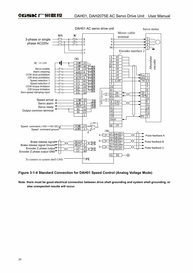
Figure 3-1-4 Standard Connection for DAH01 Speed Control (Analog Voltage Mode)
Note: there must be good electrical connection between drive shell grounding and system shell grounding, or else unexpected results will occur.
Chapter 3 Connection
21
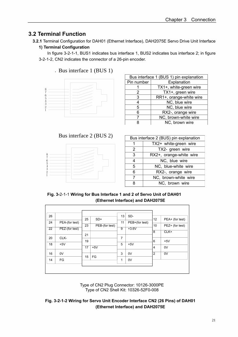
3.2 Terminal Function 3.2.1 Terminal Configuration for DAH01 (Ethernet Interface), DAH2075E Servo Drive Unit Interface
1) Terminal Configuration In figure 3-2-1-1, BUS1 indicates bus interface 1, BUS2 indicates bus interface 2; in figure
3-2-1-2, CN2 indicates the connector of a 26-pin encoder.
12
43
78
65
总线接口2(BUS2) 总线接口2(BUS2)引脚说明引脚号 引脚说明123
4567
8
TX2+ ,白绿色线
TX2- ,绿色线RX2+ ,橙白色线NC ,兰色线NC ,兰白色线
RX2- ,橙色线NC ,棕白色线
NC ,棕色线
NC ,棕色线
NC ,棕白色线RX1- ,橙色线
NC ,兰白色线NC ,兰色线RX1+ ,橙白色线TX1- ,绿色线
TX1+ ,白绿色线
87654
321
引脚说明引脚号
总线接口1(BUS1)引脚说明
总线接口1(BUS1)
56
87
34
21
Fig. 3-2-1-1 Wiring for Bus Interface 1 and 2 of Servo Unit of DAH01
(Ethernet Interface) and DAH2075E
Type of CN2 Plug Connector: 10126-3000PE Type of CN2 Shell Kit: 10326-52F0-008
Fig. 3-2-1-2 Wiring for Servo Unit Encoder Interface CN2 (26 Pins) of DAH01
(Ethernet Interface) and DAH2075E
SD+25 23
21 19
+5V 17
FG 15
SD- 13
11
+3.6V 9
7
+5V 5
0V 3
0V 1
12
10
CLK+ 8
+5V 6
0V 4
0V 2
24 22
CLK- 20 18
0V 16 FG 14
26
+5V
PEB+(for test)PEA+ (for test)
PEZ-(for test) PEB-(for test)
PEA-(for test) PEZ+ (for test)
Bus interface 2 (BUS 2)
Bus interface 1 (BUS 1)
Bus interface 2 (BUS) pin explanation 1 TX2+ white-green wire 2 TX2- green wire 3 RX2+, orange-white wire 4 NC, blue wire 5 NC, blue-white wire 6 RX2-, orange wire 7 NC, brown-white wire 8 NC, brown wire
Bus interface 1 (BUS 1) pin explanation Pin number Explanation
1 TX1+, white-green wire 2 TX1+, green wire 3 RR1+, orange-white wire 4 NC, blue wire 5 NC, blue wire 6 RX2-, orange wire 7 NC, brown-white wire 8 NC, brown wire
DAH01, DAH2075E AC Servo Drive Unit User Manual
22
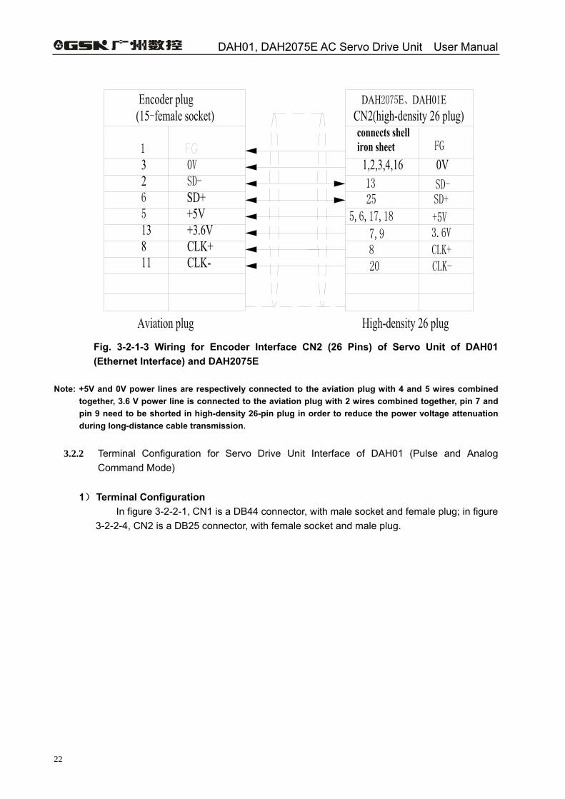
Fig. 3-2-1-3 Wiring for Encoder Interface CN2 (26 Pins) of Servo Unit of DAH01 (Ethernet Interface) and DAH2075E
Note: +5V and 0V power lines are respectively connected to the aviation plug with 4 and 5 wires combined
together, 3.6 V power line is connected to the aviation plug with 2 wires combined together, pin 7 and pin 9 need to be shorted in high-density 26-pin plug in order to reduce the power voltage attenuation during long-distance cable transmission.
3.2.2 Terminal Configuration for Servo Drive Unit Interface of DAH01 (Pulse and Analog
Command Mode)
1) Terminal Configuration In figure 3-2-2-1, CN1 is a DB44 connector, with male socket and female plug; in figure
3-2-2-4, CN2 is a DB25 connector, with female socket and male plug.
Chapter 3 Connection
23
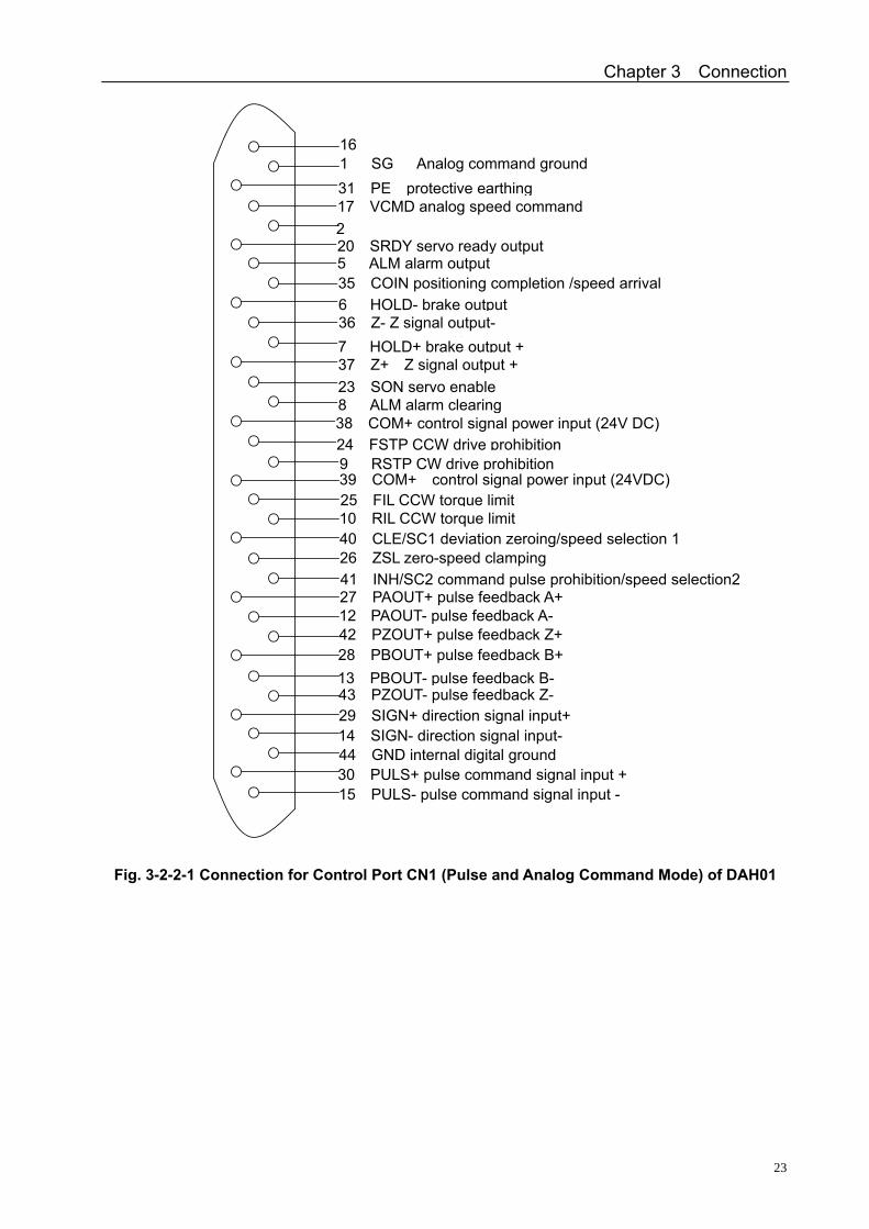
Fig. 3-2-2-1 Connection for Control Port CN1 (Pulse and Analog Command Mode) of DAH01
40 CLE/SC1 deviation zeroing/speed selection 1
41 INH/SC2 command pulse prohibition/speed selection2
39 COM+ control signal power input (24VDC) 10 RIL CCW torque limit
26 ZSL zero-speed clamping
27 PAOUT+ pulse feedback A+ 12 PAOUT- pulse feedback A- 42 PZOUT+ pulse feedback Z+28 PBOUT+ pulse feedback B+13 PBOUT- pulse feedback B-43 PZOUT- pulse feedback Z-29 SIGN+ direction signal input+14 SIGN- direction signal input- 44 GND internal digital ground
15 PULS- pulse command signal input -30 PULS+ pulse command signal input +
9 RSTP CW 驱动禁止
24 FSTP CCW 驱动禁止
38 COM+ 控制信号电源输入(24VDC)8 ALRS 报警清除
23 SON 伺服使能
37 Z+ Z 信号输出+7 HOLD+ 抱闸输出+36 Z- Z 信号输出-6 HOLD- 抱闸输出35 COIN 定位完成/速度到达5 ALM 报警输出20 SRDY 伺服准备好输出2 17 VCMD 模拟速度指令
31 PE 保护接地
1 SG Analog command ground16
31 PE protective earthing17 VCMD analog speed command
20 SRDY servo ready output5 ALM alarm output
6 HOLD- brake output 36 Z- Z signal output-
35 COIN positioning completion /speed arrival
7 HOLD+ brake output +37 Z+ Z signal output + 23 SON servo enable 8 ALM alarm clearing 38 COM+ control signal power input (24V DC) 24 FSTP CCW drive prohibition 9 RSTP CW drive prohibition
25 FIL CCW torque limit
DAH01, DAH2075E AC Servo Drive Unit User Manual
24
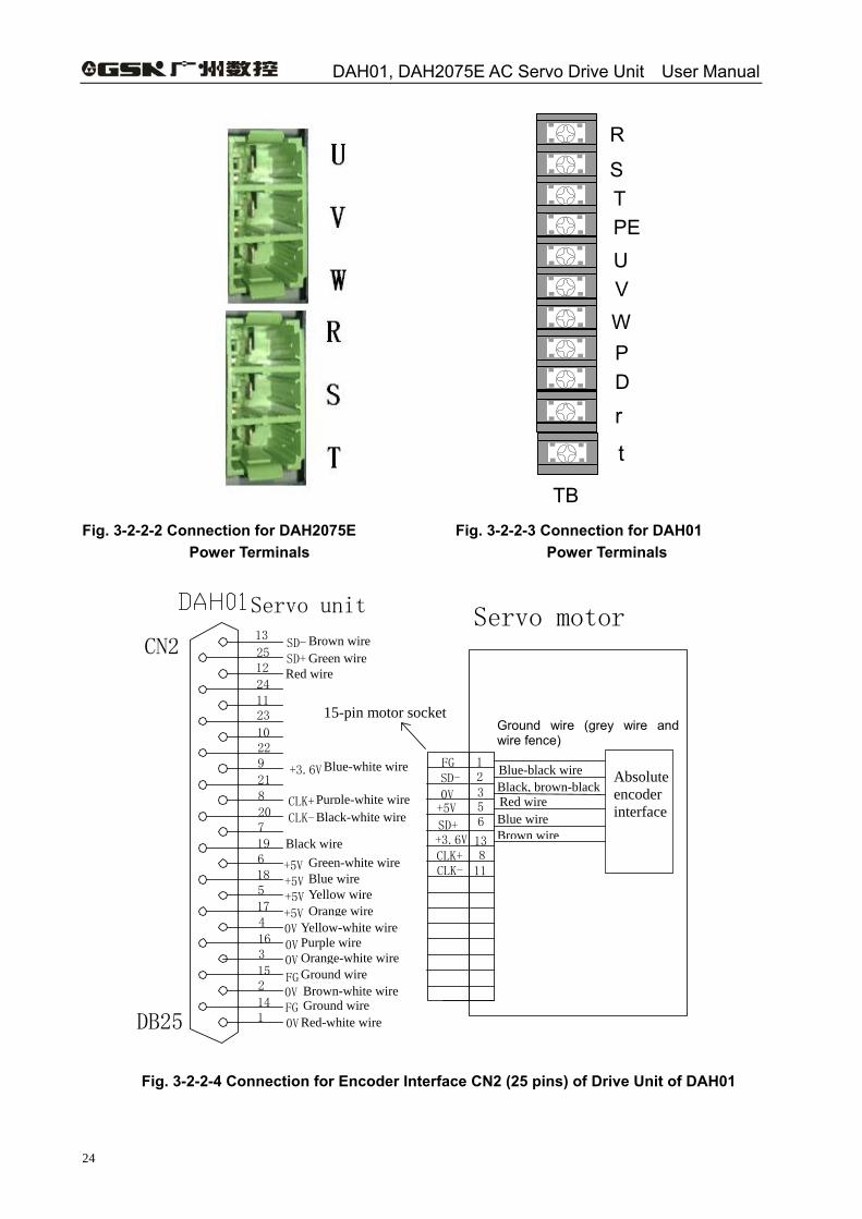
Fig. 3-2-2-2 Connection for DAH2075E Fig. 3-2-2-3 Connection for DAH01 Power Terminals Power Terminals
Fig. 3-2-2-4 Connection for Encoder Interface CN2 (25 pins) of Drive Unit of DAH01
DB25
Servo unit13 25 12 24 11 23 10 22 9
21 820 719 618 517 4
16 3
15 2
14 1
SD- SD+
+5V +5V +5V +5V 0V 0V 0V FG 0V FG 0V
CN2
+3.6V
CLK+ CLK-
棕线 绿线
蓝白线
紫白线
黑白线
绿白线 蓝线 黄线 橙线 黄白线 紫线 橙白线 地线 棕白线 地线 红白线
黑线
红线
12356
13+3.6V
+5V0V
FGSD-
SD+
Servo motor
电机的 15 针插座
CLK+CLK-
811
Red-white wire
Ground wire (grey wire and wire fence)
Absolute
encoder interface
Blue-black wire
Brown wireBlue wireRed wire Black, brown-black
R
S T PE U V W P D
r
TB
t
Brown wire Green wire
Red wire
15-pin motor socket
Blue wire
Purple-white wire Black-white wire
Black wire Green-white wire
Yellow wire Orange wire
Yellow-white wirePurple wire Orange-white wire Ground wire Brown-white wireGround wire
Blue-white wire
Chapter 3 Connection
25
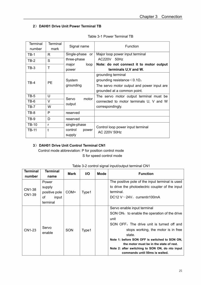
2) DAH01 Drive Unit Power Terminal TB
Table 3-1 Power Terminal TB
Terminal number
Terminal mark
Signal name Function
TB-1 R
TB-2 S
TB-3 T
Single-phase or three-phase major loop power
Major loop power input terminal AC220V 50Hz
Note: do not connect it to motor output terminals U,V and W.
TB-4 PE System grounding
grounding terminal grounding resistance<0.1Ω; The servo motor output and power input are grounded at a common point.
TB-5 U TB-6 V TB-7 W
Servo motor output
The servo motor output terminal must be connected to motor terminals U, V and W correspondingly.
TB-8 P reserved
TB-9 D reserved TB-10 r TB-11 t
single-phase control power supply
Control loop power input terminal AC 220V 50Hz
3) DAH01 Drive Unit Control Terminal CN1
Control mode abbreviation: P for position control mode S for speed control mode
Table 3-2 control signal input/output terminal CN1 Terminal number
Terminal name
Mark I/O Mode Function
CN1-38 CN1-39
Power supply positive pole of input terminal
COM+ Type1
The positive pole of the input terminal is used to drive the photoelectric coupler of the input terminal. DC12 V~24V,current≥100mA
CN1-23 Servo enable
SON Type1
Servo enable input terminal SON ON:to enable the operation of the drive unit SON OFF:The drive unit is turned off and
stops working, the motor is in free state.
Note 1: before SON OFF is switched to SON ON, the motor must be in the state of rest.
Note 2: after switching to SON ON, do nto input commands until 50ms is waited.
DAH01, DAH2075E AC Servo Drive Unit User Manual
26
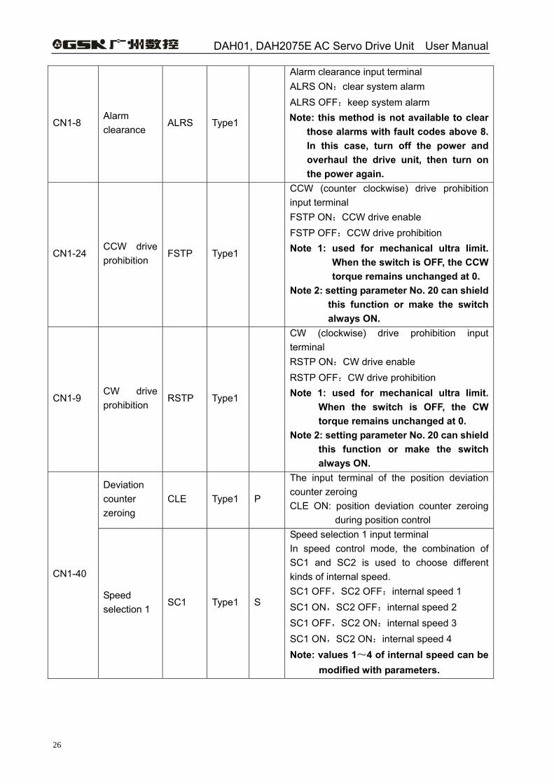
CN1-8 Alarm clearance
ALRS Type1
Alarm clearance input terminal ALRS ON:clear system alarm ALRS OFF:keep system alarm Note: this method is not available to clear
those alarms with fault codes above 8. In this case, turn off the power and overhaul the drive unit, then turn on the power again.
CN1-24 CCW drive prohibition
FSTP Type1
CCW (counter clockwise) drive prohibition input terminal FSTP ON:CCW drive enable FSTP OFF:CCW drive prohibition Note 1: used for mechanical ultra limit.
When the switch is OFF, the CCW torque remains unchanged at 0.
Note 2: setting parameter No. 20 can shield this function or make the switch always ON.
CN1-9 CW drive prohibition
RSTP Type1
CW (clockwise) drive prohibition input terminal RSTP ON:CW drive enable RSTP OFF:CW drive prohibition Note 1: used for mechanical ultra limit.
When the switch is OFF, the CW torque remains unchanged at 0.
Note 2: setting parameter No. 20 can shield this function or make the switch always ON.
Deviation counter zeroing
CLE Type1 P
The input terminal of the position deviation counter zeroing CLE ON: position deviation counter zeroing
during position control
CN1-40
Speed selection 1
SC1 Type1 S
Speed selection 1 input terminal In speed control mode, the combination of SC1 and SC2 is used to choose different kinds of internal speed. SC1 OFF,SC2 OFF:internal speed 1 SC1 ON,SC2 OFF:internal speed 2 SC1 OFF,SC2 ON:internal speed 3 SC1 ON,SC2 ON:internal speed 4 Note: values 1~4 of internal speed can be
modified with parameters.
Chapter 3 Connection
27
Continued:
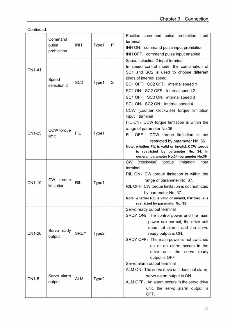
Command pulse prohibition
INH Type1 P
Position command pulse prohibition input terminal INH ON:command pulse input prohibition INH OFF:command pulse input enabled
CN1-41
Speed selection 2
SC2 Type1 S
Speed selection 2 input terminal In speed control mode, the combination of SC1 and SC2 is used to choose different kinds of internal speed. SC1 OFF,SC2 OFF:internal speed 1 SC1 ON:SC2 OFF:internal speed 2 SC1 OFF,SC2 ON:internal speed 3 SC1 ON,SC2 ON:internal speed 4
CN1-25 CCW torque limit
FIL Type1
CCW (counter clockwise) torque limitation input terminal FIL ON:CCW torque limitation is within the range of parameter No.36. FIL OFF : CCW torque limitation is not
restricted by parameter No. 36. Note: whether FIL is valid or invalid, CCW torque
is restricted by parameter No. 34. In general, parameter No.34>parameter No.36
CN1-10 CW torque limitation
RIL Type1
CW (clockwise) torque limitation input terminal RIL ON:CW torque limitation is within the
range of parameter No. 37. RIL OFF:CW torque limitation is not restricted
by parameter No. 37. Note: whether RIL is valid or invalid, CW torque is
restricted by parameter No. 35.
CN1-20 Servo ready output
SRDY Type2
Servo ready output terminal SRDY ON:The control power and the main
power are normal, the drive unit does not alarm, and the servo ready output is ON.
SRDY OFF:The main power is not switched on or an alarm occurs in the drive unit, the servo ready output is OFF.
CN1-5 Servo alarm output
ALM Type2
Servo alarm output terminal ALM ON:The servo drive unit does not alarm,
servo alarm output is ON. ALM OFF:An alarm occurs in the servo drive
unit, the servo alarm output is OFF.
DAH01, DAH2075E AC Servo Drive Unit User Manual
28
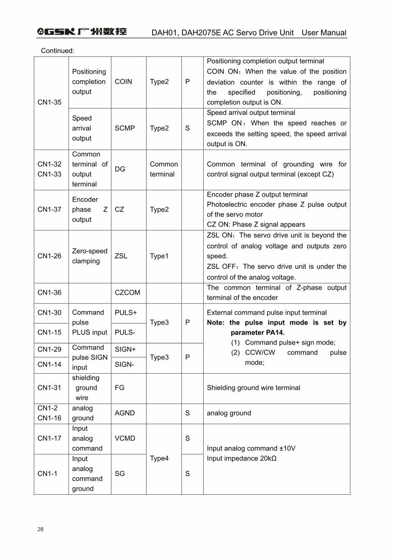
Continued:
Positioning completion output
COIN Type2 P
Positioning completion output terminal COIN ON:When the value of the position deviation counter is within the range of the specified positioning, positioning completion output is ON. CN1-35
Speed arrival output
SCMP Type2 S
Speed arrival output terminal SCMP ON:When the speed reaches or exceeds the setting speed, the speed arrival output is ON.
CN1-32 CN1-33
Common terminal of output terminal
DG Common terminal
Common terminal of grounding wire for control signal output terminal (except CZ)
CN1-37 Encoder phase Z output
CZ Type2
Encoder phase Z output terminal Photoelectric encoder phase Z pulse output of the servo motor CZ ON: Phase Z signal appears
CN1-26 Zero-speed clamping
ZSL Type1
ZSL ON:The servo drive unit is beyond the control of analog voltage and outputs zero speed. ZSL OFF:The servo drive unit is under the control of the analog voltage.
CN1-36 CZCOM The common terminal of Z-phase output terminal of the encoder
CN1-30 PULS+
CN1-15
Command pulse PLUS input PULS-
Type3 P
CN1-29 SIGN+
CN1-14
Command pulse SIGN input SIGN-
Type3 P
External command pulse input terminal Note: the pulse input mode is set by
parameter PA14. (1) Command pulse+ sign mode; (2) CCW/CW command pulse
mode;
CN1-31 shielding ground wire
FG Shielding ground wire terminal
CN1-2 CN1-16
analog ground
AGND S analog ground
CN1-17 Input analog command
VCMD S
CN1-1
Input analog command ground
SG
Type4
S
Input analog command ±10V Input impedance 20kΩ
Chapter 3 Connection
29
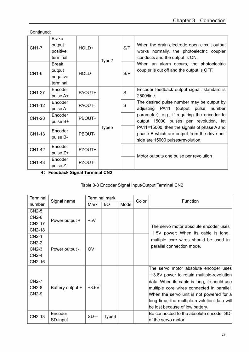
Continued:
CN1-7
Brake output positive terminal
HOLD+ S/P
CN1-6
Break output negative terminal
HOLD-
Type2
S/P
When the drain electrode open circuit output works normally, the photoelectric coupler conducts and the output is ON. When an alarm occurs, the photoelectric coupler is cut off and the output is OFF.
CN1-27 Encoder pulse A+
PAOUT+ S
CN1-12 Encoder pulse A-
PAOUT- S
CN1-28 Encoder pulse B+
PBOUT+
CN1-13 Encoder pulse B-
PBOUT-
Encoder feedback output signal, standard is 2500/line. The desired pulse number may be output by adjusting PA41 (output pulse number parameter), e.g., if requiring the encoder to output 15000 pulses per revolution, let PA41=15000, then the signals of phase A and phase B which are output from the drive unit side are 15000 pulses/revolution.
CN1-42 Encoder pulse Z+
PZOUT+
CN1-43 Encoder pulse Z-
PZOUT-
Type5
Motor outputs one pulse per revolution
4) Feedback Signal Terminal CN2
Table 3-3 Encoder Signal Input/Output Terminal CN2
Terminal mark Terminal number
Signal name Mark I/O Mode
Color Function
CN2-5 CN2-6 CN2-17 CN2-18
Power output + +5V
CN2-1 CN2-2 CN2-3 CN2-4 CN2-16
Power output - OV
The servo motor absolute encoder uses +5V power; When its cable is long, multiple core wires should be used in parallel connection mode.
CN2-7 CN2-8 CN2-9
Battery output + +3.6V
The servo motor absolute encoder uses+3.6V power to retain multiple-revolutiondata; When its cable is long, it should usemultiple core wires connected in parallel.When the servo unit is not powered for along time, the multiple-revolution data willbe lost because of low battery.
CN2-13 Encoder SD-input
SD- Type6 Be connected to the absolute encoder SD-of the servo motor
DAH01, DAH2075E AC Servo Drive Unit User Manual
30
CN2-25 Encoder SD + input
SD+ Be connected to the absolute encoderSD+ of the servo motor
CN2-14 CN2-15
Shielding ground wire
FG Shielding ground wire terminal
CN2-20 for function extension
CLK- For function Extension
CN2-8 For function Extension
CLK+ For function Extension
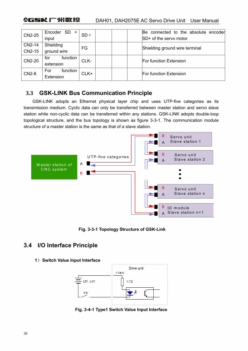
3.3 GSK-LINK Bus Communication Principle GSK-LINK adopts an Ethernet physical layer chip and uses UTP-five categories as its transmission medium. Cyclic data can only be transferred between master station and servo slave station while non-cyclic data can be transferred within any stations. GSK-LINK adopts double-loop topological structure, and the bus topology is shown as figure 3-3-1. The communication module structure of a master station is the same as that of a slave station.
M a s te r s ta tio n o f C N C sys te m
S e rvo u n it S la ve s ta tio n 1
S e rvo u n it S la ve s ta tio n 2
S e rvo u n it S la ve s ta tio n n
IO m o d u le S la ve s ta tio n n + 1
U T P -five ca te g o rie s
A
B
A
B
A
B
AB
A
B
Fig. 3-3-1 Topology Structure of GSK-Link
3.4 I/O Interface Principle
1) Switch Value Input Interface
Fig. 3-4-1 Type1 Switch Value Input Interface
Chapter 3 Connection
31
Note
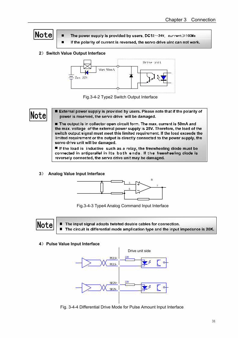
2) Switch Value Output Interface
Fig.3-4-2 Type2 Switch Output Interface
Note
3) Analog Value Input Interface
5
67
B
Fig.3-4-3 Type4 Analog Command Input Interface
Note
4) Pulse Value Input Interface
220
220
servo amplifierPULS+
PULS-
SIGN+
SIGN-
Fig. 3-4-4 Differential Drive Mode for Pulse Amount Input Interface
Drive unit side
DAH01, DAH2075E AC Servo Drive Unit User Manual
32
220
220
servo amplifier
PULS+
PULS-
SIGN+
SIGN-
R
R
VCC
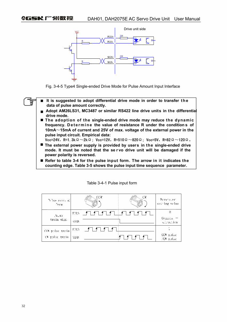
Fig. 3-4-5 Type4 Single-ended Drive Mode for Pulse Amount Input Interface
It is suggested to adopt differential drive mode in order to transfer t h e data of pulse amount correctly.Adopt AM26LS31, MC3487 or similar RS422 line drive units in the differential drive mode.The adoption of the single-ended drive mode may reduce the dynamic frequency. D e t e r m i n e the value of resistance R under the condition s of 10mA~15mA of current and 25V of max. voltage of the external power in the pulse input circuit. Empirical data:Vcc=24V,R=1.3kΩ~2kΩ; Vcc=12V,R=510Ω~820Ω; Vcc=5V,R=82Ω~120Ω。
The external power supply is provided by users in the single-ended drive mode. It must be noted that the se r vo drive unit will be damaged if the power polarity is reversed.
Refer to table 3-4 for the pulse input form. The arrow in it indicates the counting edge. Table 3-5 shows the pulse input time sequence parameter.
Table 3-4-1 Pulse input form
Drive unit side
Chapter 3 Connection
33
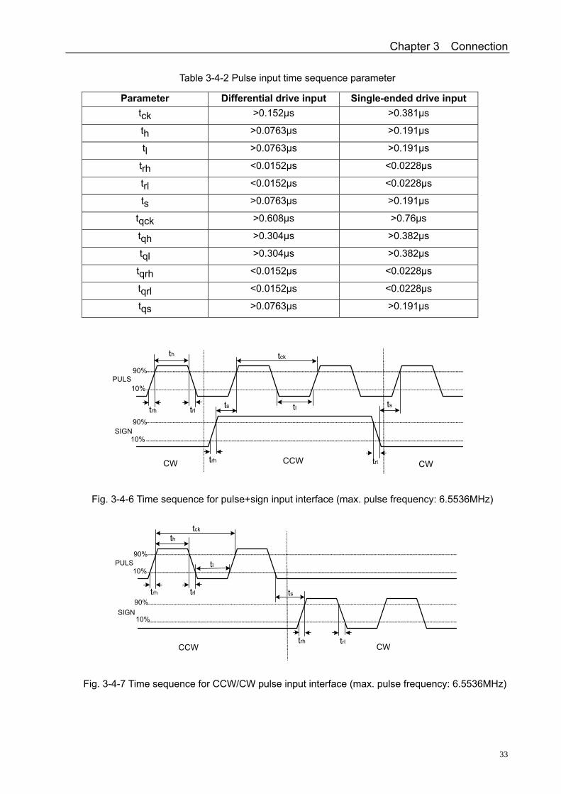
Table 3-4-2 Pulse input time sequence parameter
Parameter Differential drive input Single-ended drive input tck
>0.152μs >0.381μs
th >0.0763μs >0.191μs
tl >0.0763μs >0.191μs
trh <0.0152μs <0.0228μs
trl <0.0152μs <0.0228μs
ts >0.0763μs >0.191μs
tqck >0.608μs >0.76μs
tqh >0.304μs >0.382μs
tql >0.304μs >0.382μs
tqrh <0.0152μs <0.0228μs
tqrl <0.0152μs <0.0228μs
tqs >0.0763μs >0.191μs
th
tltrh trl ts ts
tck
trh trl
90%
90%
10%
10%
CW CWCCW
PULS
SIGN
Fig. 3-4-6 Time sequence for pulse+sign input interface (max. pulse frequency: 6.5536MHz)
th
tl
trh trl ts
tck
trh trl
10%
10%
90%
90%
CCW CW
PULS
SIGN
Fig. 3-4-7 Time sequence for CCW/CW pulse input interface (max. pulse frequency: 6.5536MHz)
DAH01, DAH2075E AC Servo Drive Unit User Manual
34
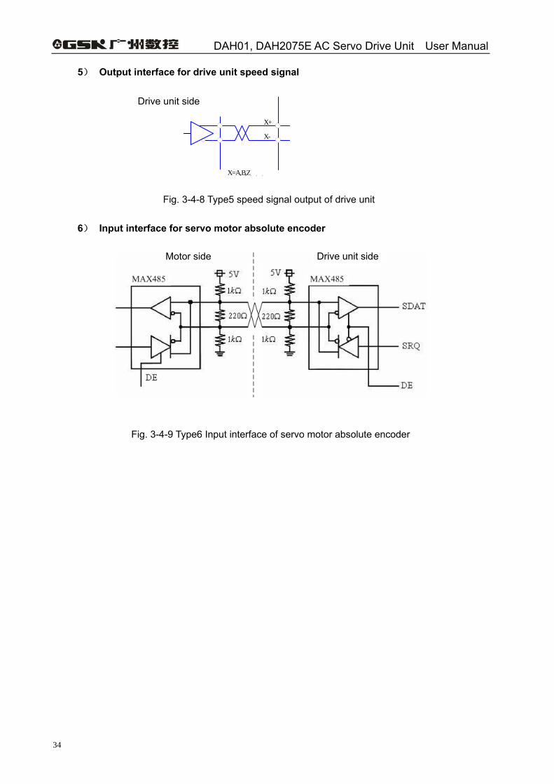
5) Output interface for drive unit speed signal
servo amplifierservo motor
X+
X-
X=A,B,Z,U,V,W
AM26LS32
Fig. 3-4-8 Type5 speed signal output of drive unit
6) Input interface for servo motor absolute encoder
Fig. 3-4-9 Type6 Input interface of servo motor absolute encoder
Drive unit side
Drive unit sideMotor side
Chapter 4 Parameter
35
CHAPTER 4 PARAMETER
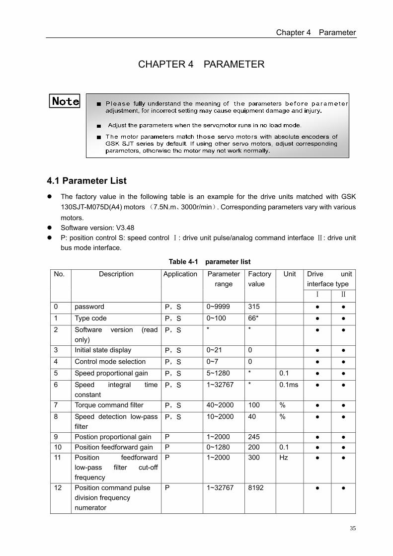
4.1 Parameter List The factory value in the following table is an example for the drive units matched with GSK
130SJT-M075D(A4) motors (7.5N.m、3000r/min). Corresponding parameters vary with various motors.
Software version: V3.48 P: position control S: speed control : drive unⅠ it pulse/analog command interface : drive unit Ⅱ
bus mode interface.
Table 4-1 parameter list
Drive unit interface type
No. Description Application Parameter range
Factory value
Unit
Ⅰ Ⅱ
0 password P,S 0~9999 315 1 Type code P,S 0~100 66* 2 Software version (read
only) P,S * *
3 Initial state display P,S 0~21 0 4 Control mode selection P,S 0~7 0 5 Speed proportional gain P,S 5~1280 * 0.1 6 Speed integral time
constant P,S 1~32767 * 0.1ms
7 Torque command filter P,S 40~2000 100 % 8 Speed detection low-pass
filter P,S 10~2000 40 %
9 Postion proportional gain P 1~2000 245 10 Position feedforward gain P 0~1280 200 0.1 11 Position feedforward
low-pass filter cut-off frequency
P 1~2000 300 Hz
12 Position command pulse division frequency numerator
P 1~32767 8192
DAH01, DAH2075E AC Servo Drive Unit User Manual
36
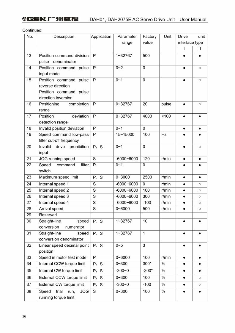
Continued: Drive unit interface type
No. Description Application Parameter range
Factory value
Unit
Ⅰ Ⅱ
13 Position command division pulse denominator
P 1~32767 500
14 Position command pulse input mode
P 0~2 0
15 Position command pulse reverse direction Position command pulse direction inversion
P 0~1 0
16 Positioning completion range
P 0~32767 20 pulse
17 Position deviation detection range
P 0~32767 4000 ×100
18 Invalid position deviation P 0~1 0 19 Speed command low-pass
filter cut-off frequency P 15~15000 100 Hz
20 Invalid drive prohibition input
P,S 0~1 0
21 JOG running speed S -6000~6000 120 r/min 22 Speed command filter
switch P 0~1 0
23 Maximum speed limit P,S 0~3000 2500 r/min 24 Internal speed 1 S -6000~6000 0 r/min 25 Internal speed 2 S -6000~6000 100 r/min 26 Internal speed 3 S -6000~6000 300 r/min 27 Internal speed 4 S -6000~6000 -100 r/min 28 Arrival speed S 0~6000 500 r/min 29 Reserved 30 Straight-line speed
conversion numerator P,S 1~32767 10
31 Straight-line speed conversion denominator
P,S 1~32767 1
32 Linear speed decimal point position
P,S 0~5 3
33 Speed in motor test mode P 0~6000 100 r/min 34 Internal CCW torque limit P,S 0~300 300* % 35 Internal CW torque limit P,S -300~0 -300* % 36 External CCW torque limit P,S 0~300 100 % 37 External CW torque limit P,S -300~0 -100 % 38 Speed trial run, JOG
running torque limit S 0~300 100 %
Chapter 4 Parameter
37
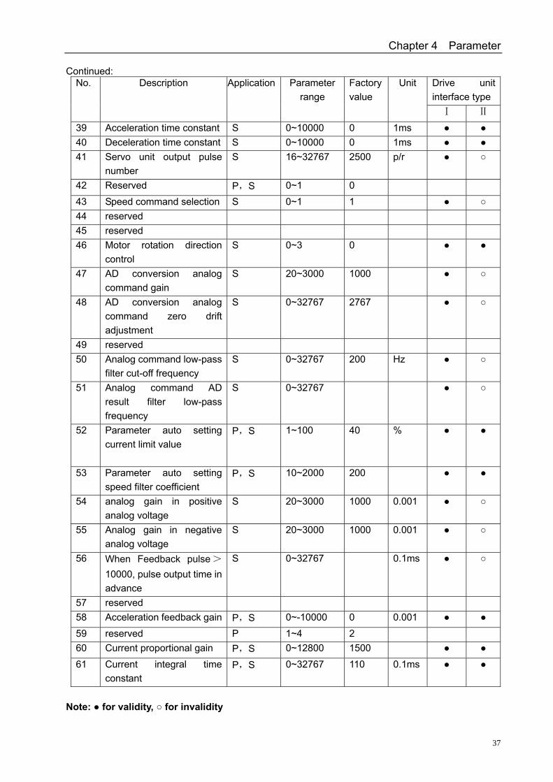
Continued: Drive unit interface type
No. Description Application Parameter range
Factory value
Unit
Ⅰ Ⅱ
39 Acceleration time constant S 0~10000 0 1ms 40 Deceleration time constant S 0~10000 0 1ms 41 Servo unit output pulse
number S 16~32767 2500 p/r
42 Reserved P,S 0~1 0 43 Speed command selection S 0~1 1 44 reserved 45 reserved 46 Motor rotation direction
control S 0~3 0
47 AD conversion analog command gain
S 20~3000 1000
48 AD conversion analog command zero drift adjustment
S 0~32767 2767
49 reserved 50 Analog command low-pass
filter cut-off frequency S 0~32767 200 Hz
51 Analog command AD result filter low-pass frequency
S 0~32767
52 Parameter auto setting current limit value
P,S 1~100 40 %
53 Parameter auto setting speed filter coefficient
P,S 10~2000 200
54 analog gain in positive analog voltage
S 20~3000 1000 0.001
55 Analog gain in negative analog voltage
S 20~3000 1000 0.001
56 When Feedback pulse>
10000, pulse output time in advance
S 0~32767 0.1ms
57 reserved 58 Acceleration feedback gain P,S 0~-10000 0 0.001 59 reserved P 1~4 2 60 Current proportional gain P,S 0~12800 1500 61 Current integral time
constant P,S 0~32767 110 0.1ms
Note: for validity, for invalidity
DAH01, DAH2075E AC Servo Drive Unit User Manual
38
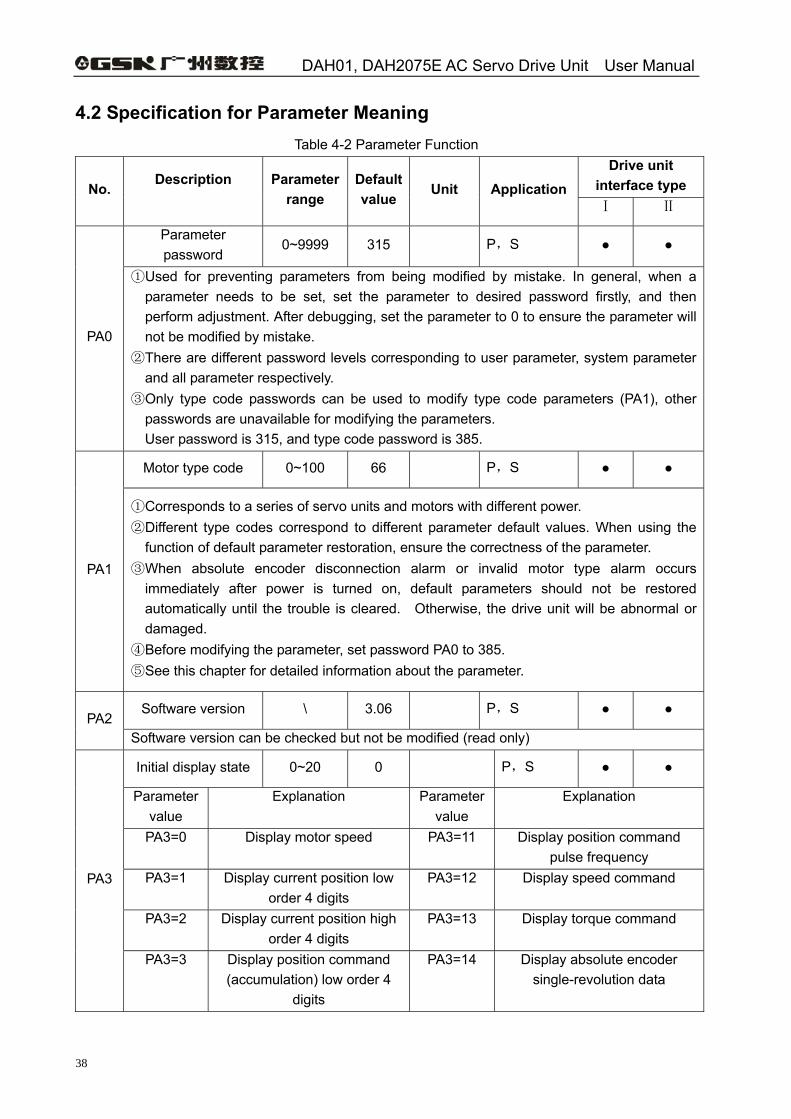
4.2 Specification for Parameter Meaning Table 4-2 Parameter Function
Drive unit interface type No.
Description
Parameter range
Default value
Unit Application Ⅰ Ⅱ
Parameter password
0~9999 315 P,S
PA0
① Used for preventing parameters from being modified by mistake. In general, when a parameter needs to be set, set the parameter to desired password firstly, and then perform adjustment. After debugging, set the parameter to 0 to ensure the parameter will not be modified by mistake.
② There are different password levels corresponding to user parameter, system parameter and all parameter respectively.
③ Only type code passwords can be used to modify type code parameters (PA1), other passwords are unavailable for modifying the parameters. User password is 315, and type code password is 385.
Motor type code 0~100 66 P,S
PA1
① Corresponds to a series of servo units and motors with different power. ② Different type codes correspond to different parameter default values. When using the
function of default parameter restoration, ensure the correctness of the parameter. ③ When absolute encoder disconnection alarm or invalid motor type alarm occurs
immediately after power is turned on, default parameters should not be restored automatically until the trouble is cleared. Otherwise, the drive unit will be abnormal or damaged.
④ Before modifying the parameter, set password PA0 to 385. ⑤ See this chapter for detailed information about the parameter.
Software version \ 3.06 P,S PA2
Software version can be checked but not be modified (read only)
Initial display state 0~20 0 P,S
Parameter value
Explanation Parameter value
Explanation
PA3=0 Display motor speed PA3=11 Display position command pulse frequency
PA3=1 Display current position low order 4 digits
PA3=12 Display speed command
PA3=2 Display current position high order 4 digits
PA3=13 Display torque command
PA3
PA3=3 Display position command (accumulation) low order 4
digits
PA3=14 Display absolute encoder single-revolution data
Chapter 4 Parameter
39
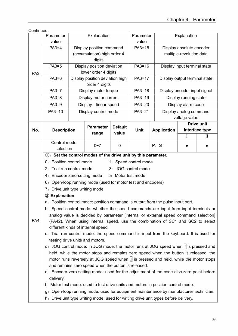
Continued: Parameter
value Explanation Parameter
value Explanation
PA3=4 Display position command (accumulation) high order 4
digits
PA3=15 Display absolute encoder multiple-revolution data
PA3=5 Display position deviation lower order 4 digits
PA3=16 Display input terminal state
PA3=6 Display position deviation high order 4 digits
PA3=17 Display output terminal state
PA3=7 Display motor torque PA3=18 Display encoder input signal PA3=8 Display motor current PA3=19 Display running state PA3=9 Display linear speed PA3=20 Display alarm code
PA3
PA3=10 Display control mode PA3=21 Display analog command voltage value
Drive unit interface type No. Description
Parameter range
Default value
Unit Application Ⅰ Ⅱ
Control mode selection
0~7 0 P,S
PA4
①:Set the control modes of the drive unit by this parameter. 0:Position control mode 1:Speed control mode 2:Trial run control mode 3:JOG control mode 4:Encoder zero-setting mode 5:Motor test mode 6:Open-loop running mode (used for motor test and encoders) 7:Drive unit type writing mode ② Explanation a:Position control mode: position command is output from the pulse input port. b:Speed control mode: whether the speed commands are input from input terminals or
analog value is decided by parameter [internal or external speed command selection] (PA42). When using internal speed, use the combination of SC1 and SC2 to select different kinds of internal speed.
c:Trial run control mode: the speed command is input from the keyboard. It is used for testing drive units and motors.
d:JOG control mode: In JOG mode, the motor runs at JOG speed when ↑ is pressed and held, while the motor stops and remains zero speed when the button is released; the motor runs reversely at JOG speed when ↓ is pressed and held, while the motor stops and remains zero speed when the button is released.
e:Encoder zero-setting mode: used for the adjustment of the code disc zero point before delivery.
f:Motor test mode: used to test drive units and motors in position control mode. g:Open-loop running mode: used for equipment maintenance by manufacturer technician. h:Drive unit type writing mode: used for writing drive unit types before delivery.
DAH01, DAH2075E AC Servo Drive Unit User Manual
40
Continued: Drive unit
interface type No. Description Parameter
range Default value
Unit Application Ⅰ Ⅰ
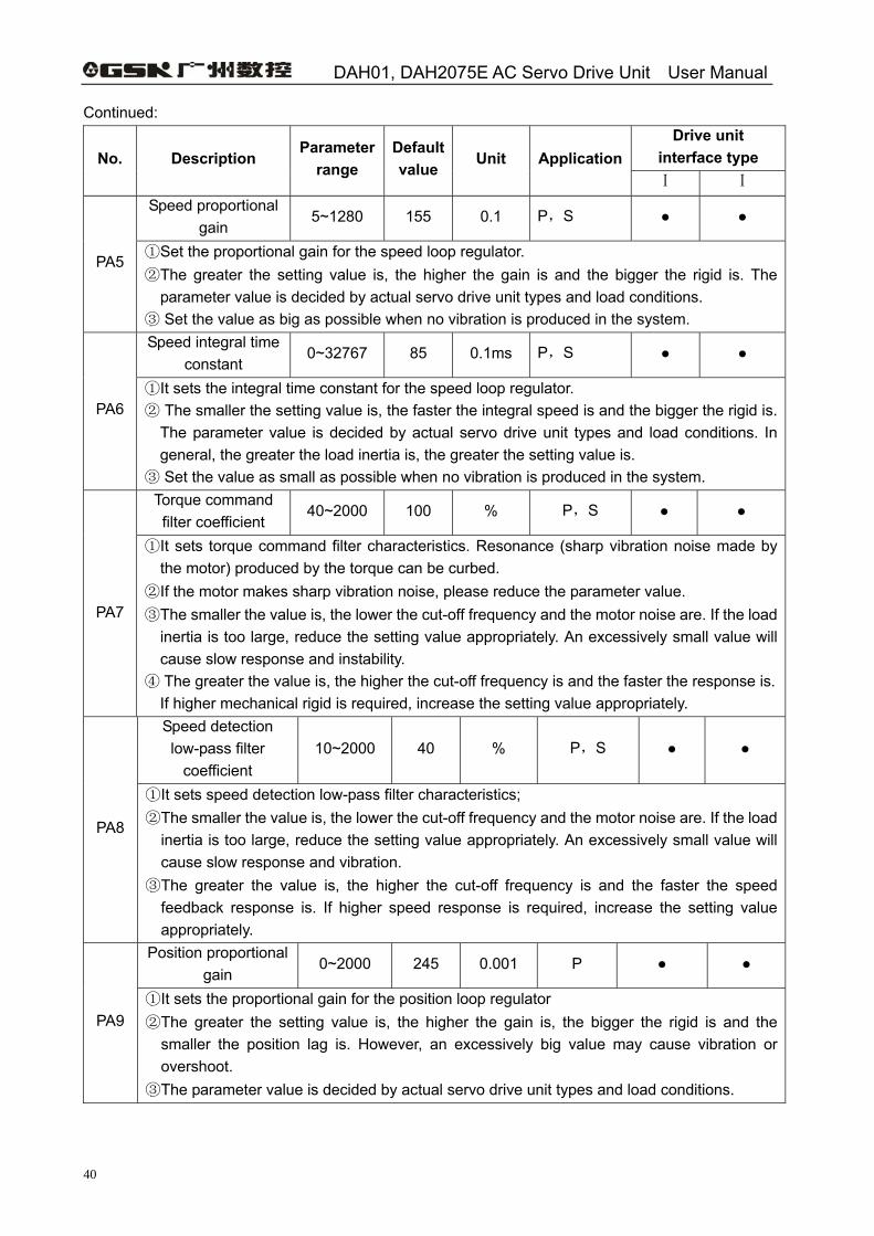
Speed proportional gain
5~1280 155 0.1 P,S
PA5 ① Set the proportional gain for the speed loop regulator. ② The greater the setting value is, the higher the gain is and the bigger the rigid is. The
parameter value is decided by actual servo drive unit types and load conditions. ③ Set the value as big as possible when no vibration is produced in the system. Speed integral time
constant 0~32767 85 0.1ms P,S
PA6 ① It sets the integral time constant for the speed loop regulator. ② The smaller the setting value is, the faster the integral speed is and the bigger the rigid is.
The parameter value is decided by actual servo drive unit types and load conditions. In general, the greater the load inertia is, the greater the setting value is.
③ Set the value as small as possible when no vibration is produced in the system. Torque command filter coefficient
40~2000 100 % P,S
PA7
① It sets torque command filter characteristics. Resonance (sharp vibration noise made by the motor) produced by the torque can be curbed.
② If the motor makes sharp vibration noise, please reduce the parameter value. ③ The smaller the value is, the lower the cut-off frequency and the motor noise are. If the load
inertia is too large, reduce the setting value appropriately. An excessively small value will cause slow response and instability.
④ The greater the value is, the higher the cut-off frequency is and the faster the response is. If higher mechanical rigid is required, increase the setting value appropriately. Speed detection low-pass filter
coefficient 10~2000 40 % P,S
PA8
① It sets speed detection low-pass filter characteristics; ② The smaller the value is, the lower the cut-off frequency and the motor noise are. If the load
inertia is too large, reduce the setting value appropriately. An excessively small value will cause slow response and vibration.
③ The greater the value is, the higher the cut-off frequency is and the faster the speed feedback response is. If higher speed response is required, increase the setting value appropriately.
Position proportional gain
0~2000 245 0.001 P
PA9 ① It sets the proportional gain for the position loop regulator ② The greater the setting value is, the higher the gain is, the bigger the rigid is and the
smaller the position lag is. However, an excessively big value may cause vibration or overshoot.
③ The parameter value is decided by actual servo drive unit types and load conditions.
Chapter 4 Parameter
41
Continued: Drive unit
interface type No. Description Parameter
range Default value
Unit Application Ⅰ Ⅰ
Position feedforward gain
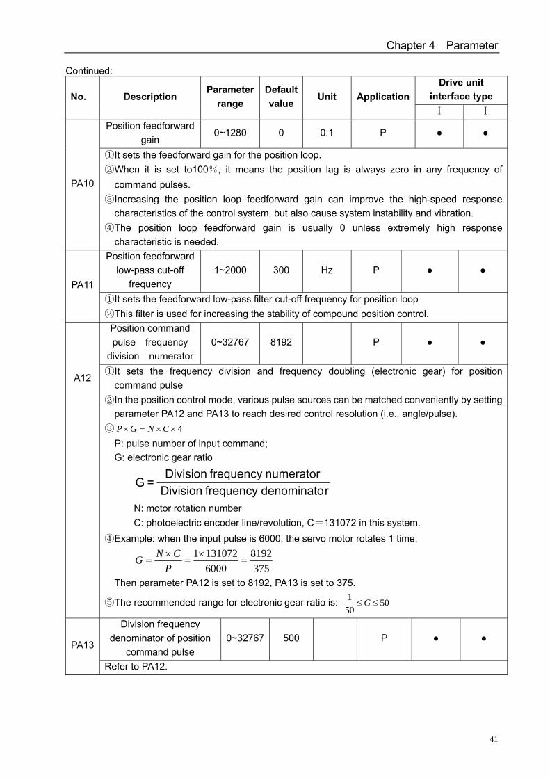
0~1280 0 0.1 P
PA10
① It sets the feedforward gain for the position loop. ② When it is set to100%, it means the position lag is always zero in any frequency of
command pulses. ③ Increasing the position loop feedforward gain can improve the high-speed response
characteristics of the control system, but also cause system instability and vibration. ④ The position loop feedforward gain is usually 0 unless extremely high response
characteristic is needed. Position feedforward
low-pass cut-off frequency
1~2000 300 Hz P PA11
① It sets the feedforward low-pass filter cut-off frequency for position loop ② This filter is used for increasing the stability of compound position control.
Position command pulse frequency
division numerator 0~32767 8192 P
A12
① It sets the frequency division and frequency doubling (electronic gear) for position command pulse
② In the position control mode, various pulse sources can be matched conveniently by setting parameter PA12 and PA13 to reach desired control resolution (i.e., angle/pulse).
③ 4××=× CNGP P: pulse number of input command; G: electronic gear ratio
rdenominatofrequency Division numeratorfrequency Division
=G
N: motor rotation number C: photoelectric encoder line/revolution, C=131072 in this system.
④ Example: when the input pulse is 6000, the servo motor rotates 1 time,
3758192
60001310721
=×
=×
=P
CNG
Then parameter PA12 is set to 8192, PA13 is set to 375.
⑤ The recommended range for electronic gear ratio is: 50501
≤≤G
Division frequency denominator of position
command pulse 0~32767 500 P
PA13
Refer to PA12.
DAH01, DAH2075E AC Servo Drive Unit User Manual
42
Continued: Drive unit
interface type No. Description Parameter
range Default value
Unit Application Ⅰ Ⅱ
Input mode of position command
pulse 0~2 0 P
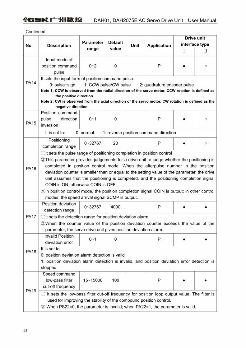
PA14 It sets the input form of position command pulse:
0: pulse+sign 1: CCW pulse/CW pulse 2: quadrature encoder pulse Note 1: CCW is observed from the radial direction of the servo motor, CCW rotation is defined as
the positive direction. Note 2: CW is observed from the axial direction of the servo motor, CW rotation is defined as the
negative direction. Position command pulse direction inversion
0~1 0 P PA15
It is set to: 0: normal 1: reverse position command direction
Positioning completion range
0~32767 20 P
PA16
① It sets the pulse range of positioning completion in position control ② This parameter provides judgements for a drive unit to judge whether the positioning is
completed in position control mode. When the afterpulse number in the position deviation counter is smaller than or equal to the setting value of the parameter, the drive unit assumes that the positioning is completed, and the positioning completion signal COIN is ON, otherwise COIN is OFF.
③ In position control mode, the position completion signal COIN is output; in other control modes, the speed arrival signal SCMP is output.
Position deviation detection range
0~32767 4000 P
PA17 ① It sets the detection range for position deviation alarm. ② When the counter value of the position deviation counter exceeds the value of the
parameter, the servo drive unit gives position deviation alarm. Invalid Position deviation error
0~1 0 P
PA18 It is set to: 0: position deviation alarm detection is valid 1: position deviation alarm detection is invalid, and position deviation error detection is stopped. Speed command
low-pass filter cut-off frequency
15~15000 100 P
PA19 ① It sets the low-pass filter cut-off frequency for position loop output value. The filter is
used for improving the stability of the compound position control. ② When PS22=0, the parameter is invalid; when PA22=1, the parameter is valid.
Chapter 4 Parameter
43
Continued: Drive unit
interface type No. Description Paramete
r range Default value
Unit Application Ⅰ Ⅱ
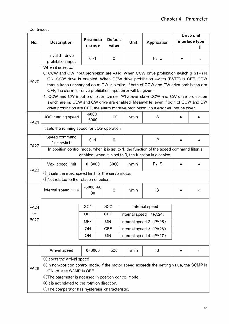
Invalid drive prohibition input
0~1 0 P,S
PA20
When it is set to: 0: CCW and CW input prohibition are valid. When CCW drive prohibition switch (FSTP) is
ON, CCW drive is enabled. When CCW drive prohibition switch (FSTP) is OFF, CCW torque keep unchanged as o; CW is similar. If both of CCW and CW drive prohibition are OFF, the alarm for drive prohibition input error will be given.
1: CCW and CW input prohibition cancel. Whatever state CCW and CW drive prohibition switch are in, CCW and CW drive are enabled. Meanwhile, even if both of CCW and CW drive prohibition are OFF, the alarm for drive prohibition input error will not be given.
JOG running speed -6000~ 6000
100 r/min S PA21
It sets the running speed for JOG operation
Speed command filter switch
0~1 0 P PA22
In position control mode, when it is set to 1, the function of the speed command filter is enabled; when it is set to 0, the function is disabled.
Max. speed limit 0~3000 3000 r/min P,S PA23
① It sets the max. speed limit for the servo motor. ② Not related to the rotation direction.
Internal speed 1~4 -6000~60
00 0 r/min S
PA24~
PA27
SC1 SC2 Internal speed
OFF OFF Internal speed (PA24)
OFF ON Internal speed 2(PA25)
ON OFF Internal speed 3(PA26) ON ON Internal speed 4(PA27)
Arrival speed 0~6000 500 r/min S
PA28
① It sets the arrival speed ② In non-position control mode, if the motor speed exceeds the setting value, the SCMP is
ON, or else SCMP is OFF. ③ The parameter is not used in position control mode. ④ It is not related to the rotation direction. ⑤ The comparator has hysteresis characteristic.
DAH01, DAH2075E AC Servo Drive Unit User Manual
44
Continued: Drive unit
interface type No. Description Parameter
range Default value
Unit Application Ⅰ Ⅱ
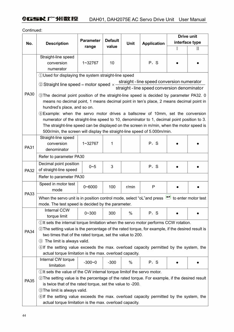
Straight-line speed conversion numerator
1~32767 10 P,S
PA30
① Used for displaying the system straight-line speed
② rdenominato conversion speed line-straight
numerator conversion speed line-straight speed motorspeed line Straight ×=
③ The decimal point position of the straight-line speed is decided by parameter PA32. 0 means no decimal point, 1 means decimal point in ten’s place, 2 means decimal point in hundred’s place, and so on.
④ Example: when the servo motor drives a ballscrew of 10mm, set the conversion numerator of the straight-line speed to 10, denominator to 1, decimal point position to 3. The straight-line speed can be displayed on the screen in m/min, when the motor speed is 500r/min, the screen will display the straight-line speed of 5.000m/min.
Straight-line speed conversion
denominator 1~32767 1 P,S
PA31
Refer to parameter PA30
Decimal point position of straight-line speed
0~5 3 P,S PA32
Refer to parameter PA30
Speed in motor test mode
0~6000 100 r/min P
PA33 When the servo unit is in position control mode, select “oL”and press to enter motor test mode. The test speed is decided by the parameter.
Internal CCW torque limit
0~300 300 % P,S
PA34
① It sets the internal torque limitation when the servo motor performs CCW rotation. ② The setting value is the percentage of the rated torque, for example, if the desired result is
two times that of the rated torque, set the value to 200. ③ The limit is always valid. ④ If the setting value exceeds the max. overload capacity permitted by the system, the
actual torque limitation is the max. overload capacity. Internal CW torque
limitation -300~0 -300 % P,S
PA35
① It sets the value of the CW internal torque limitof the servo motor. ② The setting value is the percentage of the rated torque. For example, if the desired result
is twice that of the rated torque, set the value to -200. ③ The limit is always valid. ④ If the setting value exceeds the max. overload capacity permitted by the system, the
actual torque limitation is the max. overload capacity.
Chapter 4 Parameter
45
Continued: Drive unit
interface type No. Description Parameter
range Default value
Unit Application Ⅰ Ⅱ
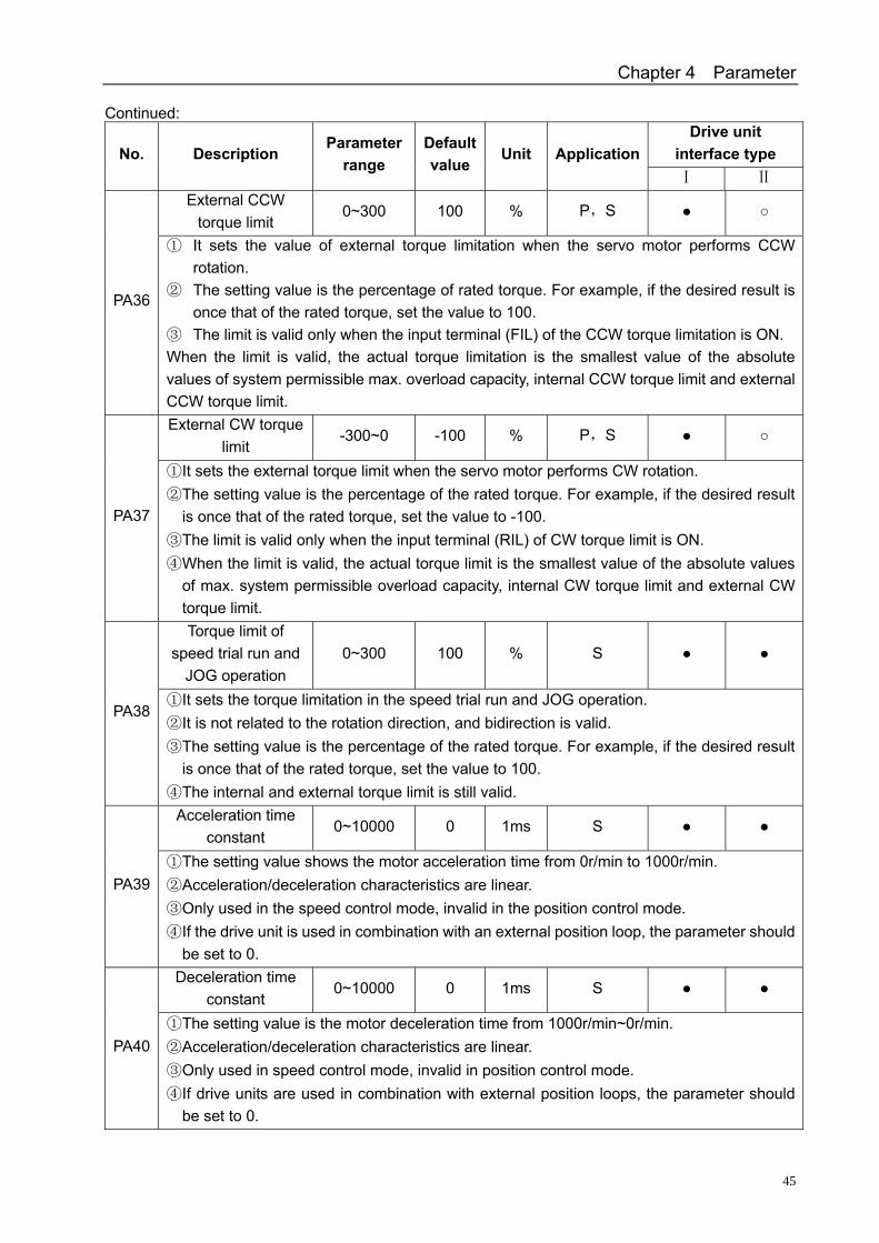
External CCW torque limit
0~300 100 % P,S
PA36
① It sets the value of external torque limitation when the servo motor performs CCW rotation.
② The setting value is the percentage of rated torque. For example, if the desired result is once that of the rated torque, set the value to 100.
③ The limit is valid only when the input terminal (FIL) of the CCW torque limitation is ON. When the limit is valid, the actual torque limitation is the smallest value of the absolute values of system permissible max. overload capacity, internal CCW torque limit and external CCW torque limit. External CW torque
limit -300~0 -100 % P,S
PA37
① It sets the external torque limit when the servo motor performs CW rotation. ② The setting value is the percentage of the rated torque. For example, if the desired result
is once that of the rated torque, set the value to -100. ③ The limit is valid only when the input terminal (RIL) of CW torque limit is ON. ④ When the limit is valid, the actual torque limit is the smallest value of the absolute values
of max. system permissible overload capacity, internal CW torque limit and external CW torque limit. Torque limit of
speed trial run and JOG operation
0~300 100 % S
PA38 ① It sets the torque limitation in the speed trial run and JOG operation. ② It is not related to the rotation direction, and bidirection is valid. ③ The setting value is the percentage of the rated torque. For example, if the desired result
is once that of the rated torque, set the value to 100. ④ The internal and external torque limit is still valid.
Acceleration time constant
0~10000 0 1ms S
PA39 ① The setting value shows the motor acceleration time from 0r/min to 1000r/min. ② Acceleration/deceleration characteristics are linear. ③ Only used in the speed control mode, invalid in the position control mode. ④ If the drive unit is used in combination with an external position loop, the parameter should
be set to 0. Deceleration time
constant 0~10000 0 1ms S
PA40 ① The setting value is the motor deceleration time from 1000r/min~0r/min. ② Acceleration/deceleration characteristics are linear. ③ Only used in speed control mode, invalid in position control mode. ④ If drive units are used in combination with external position loops, the parameter should
be set to 0.
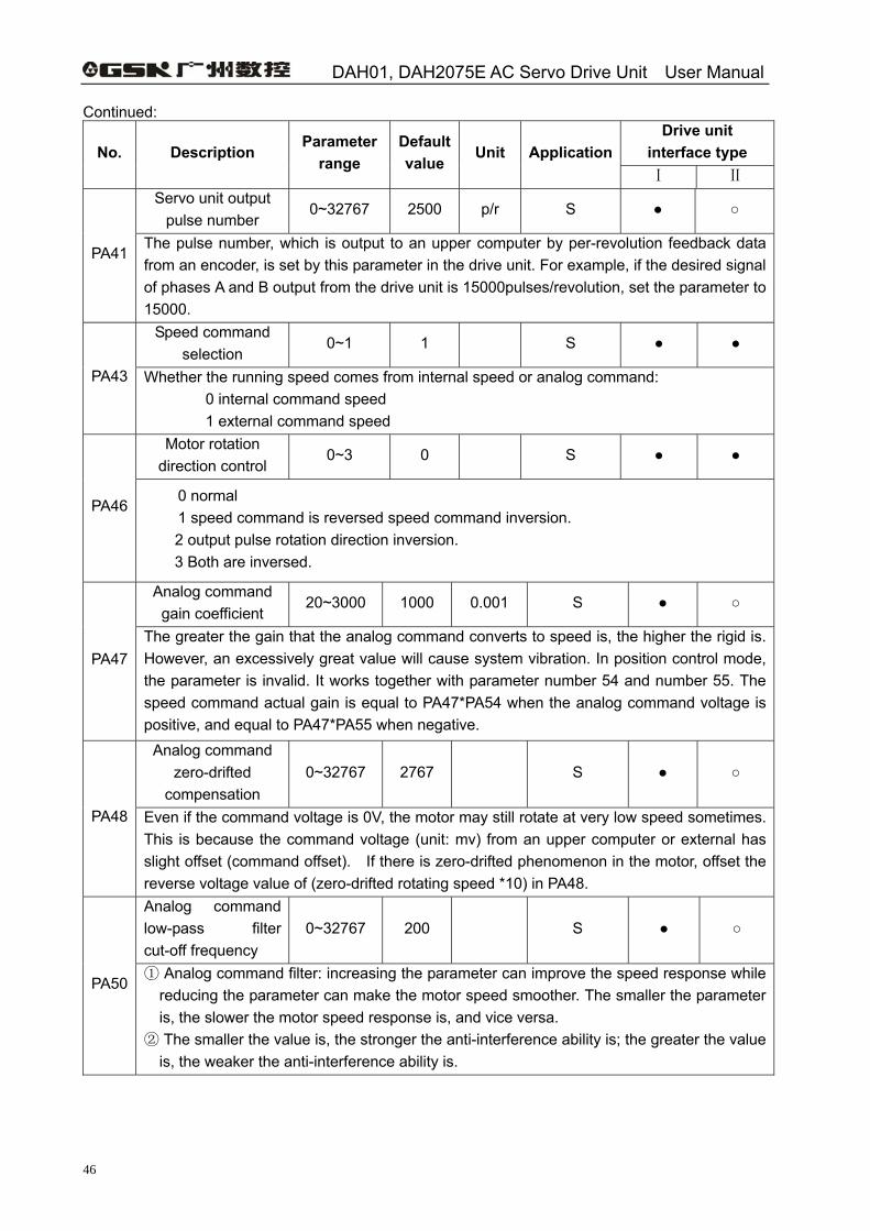
DAH01, DAH2075E AC Servo Drive Unit User Manual
46
Continued: Drive unit
interface type No. Description Parameter
range Default value
Unit Application Ⅰ Ⅱ
Servo unit output pulse number
0~32767 2500 p/r S
PA41 The pulse number, which is output to an upper computer by per-revolution feedback data from an encoder, is set by this parameter in the drive unit. For example, if the desired signal of phases A and B output from the drive unit is 15000pulses/revolution, set the parameter to 15000.
Speed command selection
0~1 1 S
PA43 Whether the running speed comes from internal speed or analog command: 0 internal command speed 1 external command speed
Motor rotation direction control
0~3 0 S
PA46 0 normal 1 speed command is reversed speed command inversion.
2 output pulse rotation direction inversion. 3 Both are inversed.
Analog command gain coefficient
20~3000 1000 0.001 S
PA47 The greater the gain that the analog command converts to speed is, the higher the rigid is. However, an excessively great value will cause system vibration. In position control mode, the parameter is invalid. It works together with parameter number 54 and number 55. The speed command actual gain is equal to PA47*PA54 when the analog command voltage is positive, and equal to PA47*PA55 when negative.
Analog command zero-drifted
compensation 0~32767 2767 S
PA48 Even if the command voltage is 0V, the motor may still rotate at very low speed sometimes. This is because the command voltage (unit: mv) from an upper computer or external has slight offset (command offset). If there is zero-drifted phenomenon in the motor, offset the reverse voltage value of (zero-drifted rotating speed *10) in PA48. Analog command low-pass filter cut-off frequency
0~32767 200 S
PA50 ① Analog command filter: increasing the parameter can improve the speed response while
reducing the parameter can make the motor speed smoother. The smaller the parameter is, the slower the motor speed response is, and vice versa.
② The smaller the value is, the stronger the anti-interference ability is; the greater the value is, the weaker the anti-interference ability is.
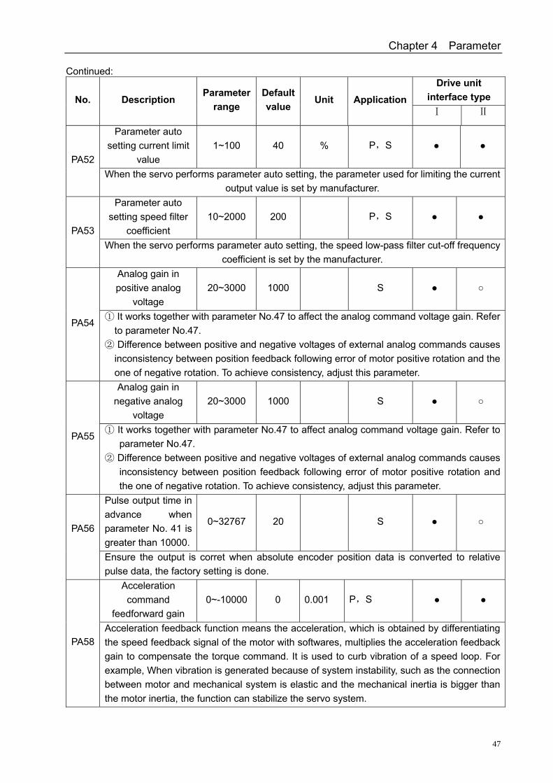
Chapter 4 Parameter
47
Continued: Drive unit
interface type No. Description Parameter
range Default value
Unit Application Ⅰ Ⅱ
Parameter auto setting current limit
value 1~100 40 % P,S
PA52 When the servo performs parameter auto setting, the parameter used for limiting the current
output value is set by manufacturer. Parameter auto
setting speed filter coefficient
10~2000 200 P,S PA53
When the servo performs parameter auto setting, the speed low-pass filter cut-off frequency coefficient is set by the manufacturer.
Analog gain in positive analog
voltage 20~3000 1000 S
PA54 ① It works together with parameter No.47 to affect the analog command voltage gain. Refer
to parameter No.47. ② Difference between positive and negative voltages of external analog commands causes
inconsistency between position feedback following error of motor positive rotation and the one of negative rotation. To achieve consistency, adjust this parameter. Analog gain in
negative analog voltage
20~3000 1000 S
PA55 ① It works together with parameter No.47 to affect analog command voltage gain. Refer to
parameter No.47. ② Difference between positive and negative voltages of external analog commands causes
inconsistency between position feedback following error of motor positive rotation and the one of negative rotation. To achieve consistency, adjust this parameter.
Pulse output time in advance when parameter No. 41 is greater than 10000.
0~32767 20 S PA56
Ensure the output is corret when absolute encoder position data is converted to relative pulse data, the factory setting is done.
Acceleration command
feedforward gain 0~-10000 0 0.001 P,S
PA58 Acceleration feedback function means the acceleration, which is obtained by differentiating the speed feedback signal of the motor with softwares, multiplies the acceleration feedback gain to compensate the torque command. It is used to curb vibration of a speed loop. For example, When vibration is generated because of system instability, such as the connection between motor and mechanical system is elastic and the mechanical inertia is bigger than the motor inertia, the function can stabilize the servo system.
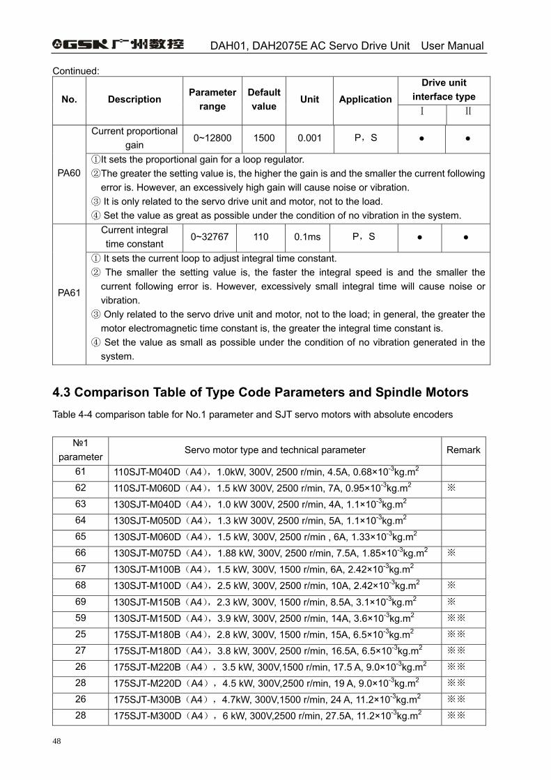
DAH01, DAH2075E AC Servo Drive Unit User Manual
48
Continued: Drive unit
interface type No. Description Parameter
range Default value
Unit Application Ⅰ Ⅱ
Current proportional gain
0~12800 1500 0.001 P,S
PA60 ①It sets the proportional gain for a loop regulator. ②The greater the setting value is, the higher the gain is and the smaller the current following
error is. However, an excessively high gain will cause noise or vibration. ③ It is only related to the servo drive unit and motor, not to the load. ④ Set the value as great as possible under the condition of no vibration in the system.
Current integral time constant
0~32767 110 0.1ms P,S
PA61
① It sets the current loop to adjust integral time constant. ② The smaller the setting value is, the faster the integral speed is and the smaller the
current following error is. However, excessively small integral time will cause noise or vibration.
③ Only related to the servo drive unit and motor, not to the load; in general, the greater the motor electromagnetic time constant is, the greater the integral time constant is.
④ Set the value as small as possible under the condition of no vibration generated in the system.
4.3 Comparison Table of Type Code Parameters and Spindle Motors Table 4-4 comparison table for No.1 parameter and SJT servo motors with absolute encoders
1 parameter
Servo motor type and technical parameter Remark
61 110SJT-M040D(A4),1.0kW, 300V, 2500 r/min, 4.5A, 0.68×10⁻³kg.m2 62 110SJT-M060D(A4),1.5 kW 300V, 2500 r/min, 7A, 0.95×10⁻³kg.m2 ※ 63 130SJT-M040D(A4),1.0 kW 300V, 2500 r/min, 4A, 1.1×10⁻³kg.m2 64 130SJT-M050D(A4),1.3 kW 300V, 2500 r/min, 5A, 1.1×10⁻³kg.m2 65 130SJT-M060D(A4),1.5 kW, 300V, 2500 r/min , 6A, 1.33×10⁻³kg.m2 66 130SJT-M075D(A4),1.88 kW, 300V, 2500 r/min, 7.5A, 1.85×10⁻³kg.m2 ※ 67 130SJT-M100B(A4),1.5 kW, 300V, 1500 r/min, 6A, 2.42×10⁻³kg.m2 68 130SJT-M100D(A4),2.5 kW, 300V, 2500 r/min, 10A, 2.42×10⁻³kg.m2 ※
69 130SJT-M150B(A4),2.3 kW, 300V, 1500 r/min, 8.5A, 3.1×10⁻³kg.m2 ※ 59 130SJT-M150D(A4),3.9 kW, 300V, 2500 r/min, 14A, 3.6×10⁻³kg.m2 ※※ 25 175SJT-M180B(A4),2.8 kW, 300V, 1500 r/min, 15A, 6.5×10⁻³kg.m2 ※※ 27 175SJT-M180D(A4),3.8 kW, 300V, 2500 r/min, 16.5A, 6.5×10⁻³kg.m2 ※※ 26 175SJT-M220B(A4),3.5 kW, 300V,1500 r/min, 17.5 A, 9.0×10⁻³kg.m2 ※※ 28 175SJT-M220D(A4),4.5 kW, 300V,2500 r/min, 19 A, 9.0×10⁻³kg.m2 ※※ 26 175SJT-M300B(A4),4.7kW, 300V,1500 r/min, 24 A, 11.2×10⁻³kg.m2 ※※ 28 175SJT-M300D(A4),6 kW, 300V,2500 r/min, 27.5A, 11.2×10⁻³kg.m2 ※※

Chapter 4 Parameter
49
Note
Drive units matching the motors with ※ in the above table must adopt thickene
Drive untis matching the motors with ※※ must adopt thickened radiators and radiators.
fans.
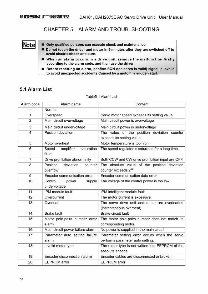
DAH01, DAH2075E AC Servo Drive Unit User Manual
50
CHAPTER 5 ALARM AND TROUBLSHOOTING
Only qualified persons can execute check and maintenance. Do not touch the driver and motor in 5 minutes after they are switched off to avoid electric shock and burn.
When an alarm occurs in a drive unit, remove the malfunction firstly according to the alarm code, and then use the driver.
Before resetting an alarm, confirm SON (the servo is valid) signal is invalid to avoid unexpected accidents Caused by a motor’s sudden start.
Note
5.1 Alarm List
Table5-1 Alarm List
Alarm code Alarm name Content -- Normal 1 Overspeed Servo motor speed exceeds its setting value 2 Main circuit overvoltage Main circuit power is overvoltage
3 Main circuit undervoltage Main circuit power is undervoltage 4 Position deviation The value of the position deviation counter
exceeds its setting value. 5 Motor overheat Motor temperature is too high. 6 Speed amplifier saturation
fault The speed regulator is saturated for a long time.
7 Drive prohibition abnormality Both CCW and CW drive prohibition input are OFF.8 Position deviation counter
overflow The absolute value of the position deviation counter exceeds 230.
9 Encoder communication error Encoder communication data error 10 Control power supply
undervoltage The voltage of the control power is too low.
11 IPM module fault IPM intelligent module fault 12 Overcurrent The motor current is excessive. 13 Overload The servo drive unit and motor are overloaded
(instantaneous overheat) 14 Brake fault Brake circuit fault 15 Motor pole-pairs number error
alarm The motor pole-pairs number does not match its corresponding motor.
16 Main circuit power failure alarm No power is supplied in the main circuit. 17 Parameter auto setting failure
alarm Parameter setting error occurs when the servo performs parameter auto setting.
18 Invalid motor type The motor type is not written into EEPROM of the absolute encode.
19 Encoder disconnection alarm Encoder cables are disconnected or broken. 20 EEPROM error EEPROM error
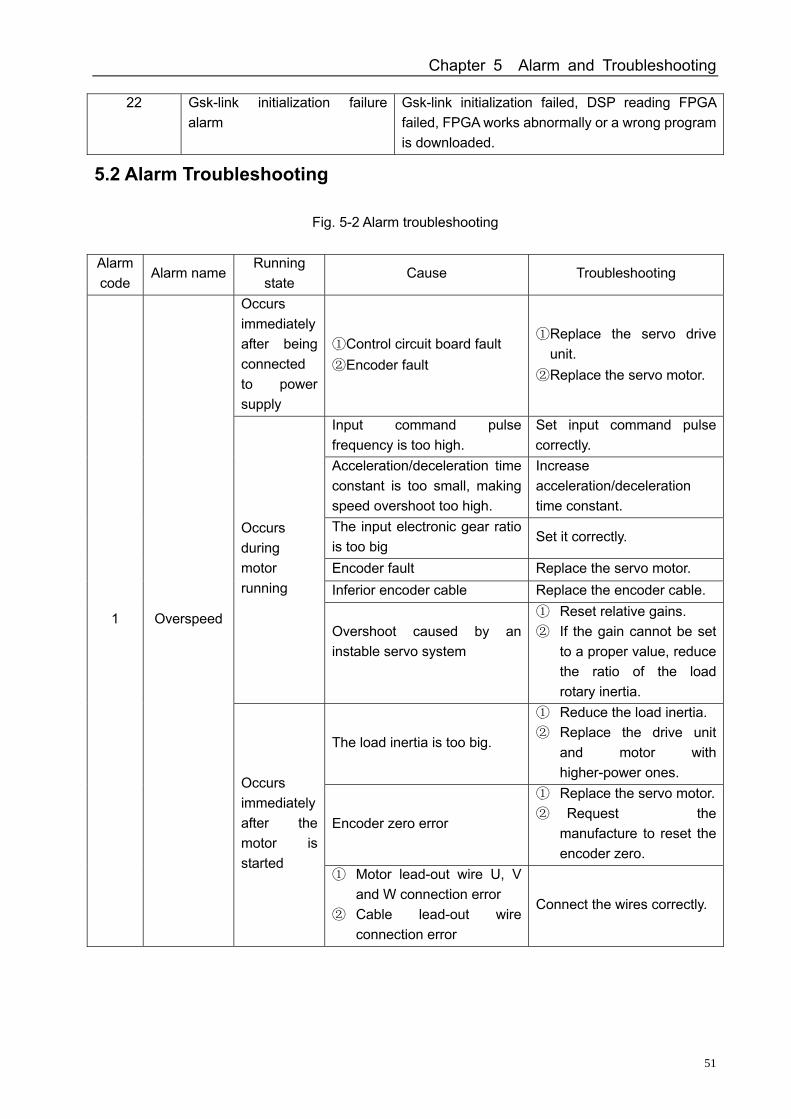
Chapter 5 Alarm and Troubleshooting
51
22 Gsk-link initialization failure alarm
Gsk-link initialization failed, DSP reading FPGA failed, FPGA works abnormally or a wrong program is downloaded.
5.2 Alarm Troubleshooting
Fig. 5-2 Alarm troubleshooting
Alarm code
Alarm name Running
state Cause Troubleshooting
Occurs immediately after being connected to power supply
① Control circuit board fault ② Encoder fault
① Replace the servo drive unit.
② Replace the servo motor.
Input command pulse frequency is too high.
Set input command pulse correctly.
Acceleration/deceleration time constant is too small, making speed overshoot too high.
Increase acceleration/deceleration time constant.
The input electronic gear ratio is too big
Set it correctly.
Encoder fault Replace the servo motor. Inferior encoder cable Replace the encoder cable.
Occurs during motor running
Overshoot caused by an instable servo system
① Reset relative gains. ② If the gain cannot be set
to a proper value, reduce the ratio of the load rotary inertia.
The load inertia is too big.
① Reduce the load inertia. ② Replace the drive unit
and motor with higher-power ones.
Encoder zero error
① Replace the servo motor.② Request the
manufacture to reset the encoder zero.
1 Overspeed
Occurs immediately after the motor is started
① Motor lead-out wire U, V and W connection error
② Cable lead-out wire connection error
Connect the wires correctly.
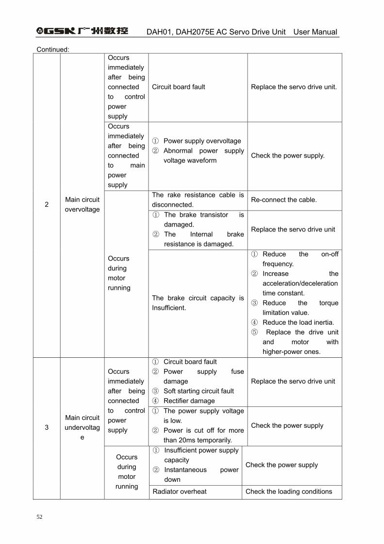
DAH01, DAH2075E AC Servo Drive Unit User Manual
52
Continued: Occurs immediately after being connected to control power supply
Circuit board fault Replace the servo drive unit.
Occurs immediately after being connected to main power supply
① Power supply overvoltage ② Abnormal power supply
voltage waveform
Check the power supply.
The rake resistance cable is disconnected.
Re-connect the cable.
① The brake transistor is damaged.
② The Internal brake resistance is damaged.
Replace the servo drive unit
2 Main circuit overvoltage
Occurs during motor running
The brake circuit capacity is Insufficient.
① Reduce the on-off frequency.
② Increase the acceleration/deceleration time constant.
③ Reduce the torque limitation value.
④ Reduce the load inertia. ⑤ Replace the drive unit
and motor with higher-power ones.
① Circuit board fault ② Power supply fuse
damage ③ Soft starting circuit fault ④ Rectifier damage
Replace the servo drive unit Occurs immediately after being connected to control power supply
① The power supply voltage is low.
② Power is cut off for more than 20ms temporarily.
Check the power supply
① Insufficient power supply capacity
② Instantaneous power down
Check the power supply
3 Main circuit undervoltag
e
Occurs during motor
running Radiator overheat Check the loading conditions
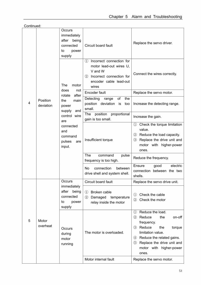
Chapter 5 Alarm and Troubleshooting
53
Continued: Occurs immediately after being connected to power supply
Circuit board fault
Replace the servo driver.
① Incorrect connection for motor lead-out wires U, V and W
② Incorrect connection for encoder cable lead-out wires
Connect the wires correctly.
Encoder fault Replace the servo motor.
Detecting range of the position deviation is too small.
Increase the detecting range.
The position proportional gain is too small.
Increase the gain.
Insufficient torque
① Check the torque limitation value.
② Reduce the load capacity. ③ Replace the drive unit and
motor with higher-power ones.
The command pulse frequency is too high.
Reduce the frequency.
4 Position deviation
The motor does not rotate after the main power supply and control wire are connected and command pulses are input.
No connection between drive shell and system shell.
Ensure good electric connection between the two shells.
Circuit board fault Replace the servo drive unit. Occurs immediately after being connected to power supply
① Broken cable ② Damaged temperature
relay inside the motor
① Check the cable ② Check the motor
The motor is overloaded.
① Reduce the load. ② Reduce the on-off
frequency. ③ Reduce the torque
limitation value. ④ Reduce the related gains. ⑤ Replace the drive unit and
motor with higher-power ones.
5 Motor overheat
Occurs during motor running
Motor internal fault Replace the servo motor.
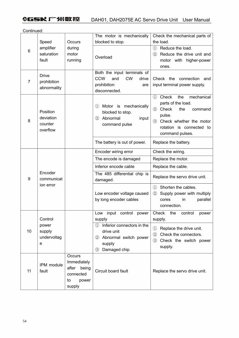
DAH01, DAH2075E AC Servo Drive Unit User Manual
54
Continued: The motor is mechanically blocked to stop.
Check the mechanical parts of the load.
6
Speed amplifier saturation fault
Occurs during motor running
Overload
① Reduce the load. ② Reduce the drive unit and
motor with higher-power ones.
7 Drive prohibition abnormality
Both the input terminals of CCW and CW drive prohibition are disconnected.
Check the connection and input terminal power supply.
① Motor is mechanically blocked to stop.
② Abnormal input command pulse
① Check the mechanical parts of the load.
② Check the command pulse.
③ Check whether the motor rotation is connected to command pulses.
8
Position deviation counter overflow
The battery is out of power. Replace the battery.
Encoder wiring error Check the wiring.
The encode is damaged Replace the motor.
Inferior encode cable Replace the cable.
The 485 differential chip is damaged.
Replace the servo drive unit. 9 Encoder communication error
Low encoder voltage caused by long encoder cables
① Shorten the cables. ② Supply power with multiply
cores in parallel connection.
Low input control power supply
Check the control power supply.
10
Control power supply undervoltage
① Inferior connectors in the
drive unit ② Abnormal switch power
supply ③ Damaged chip
① Replace the drive unit. ② Check the connectors. ③ Check the switch power
supply.
11 IPM module fault
Occurs Immediately after being connected to power supply
Circuit board fault Replace the servo drive unit.
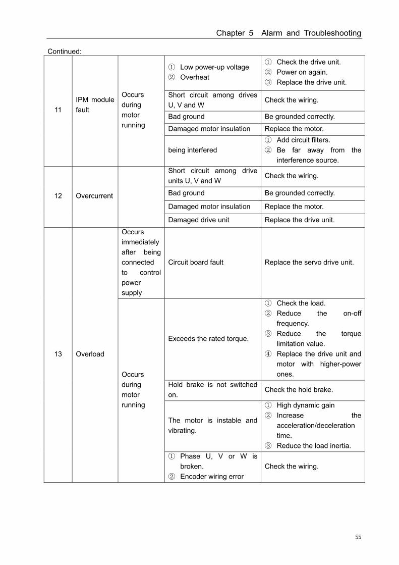
Chapter 5 Alarm and Troubleshooting
55
Continued:
① Low power-up voltage ② Overheat
① Check the drive unit. ② Power on again. ③ Replace the drive unit.
Short circuit among drives U, V and W
Check the wiring.
Bad ground Be grounded correctly.
Damaged motor insulation Replace the motor.
11 IPM module fault
Occurs during motor running
being interfered ① Add circuit filters. ② Be far away from the
interference source. Short circuit among drive units U, V and W
Check the wiring.
Bad ground Be grounded correctly.
Damaged motor insulation Replace the motor. 12 Overcurrent
Damaged drive unit Replace the drive unit.
Occurs immediately after being connected to control power supply
Circuit board fault Replace the servo drive unit.
Exceeds the rated torque.
① Check the load. ② Reduce the on-off
frequency. ③ Reduce the torque
limitation value. ④ Replace the drive unit and
motor with higher-power ones.
Hold brake is not switched on.
Check the hold brake.
The motor is instable and vibrating.
① High dynamic gain ② Increase the
acceleration/deceleration time.
③ Reduce the load inertia.
13 Overload
Occurs during motor running
① Phase U, V or W is broken.
② Encoder wiring error Check the wiring.
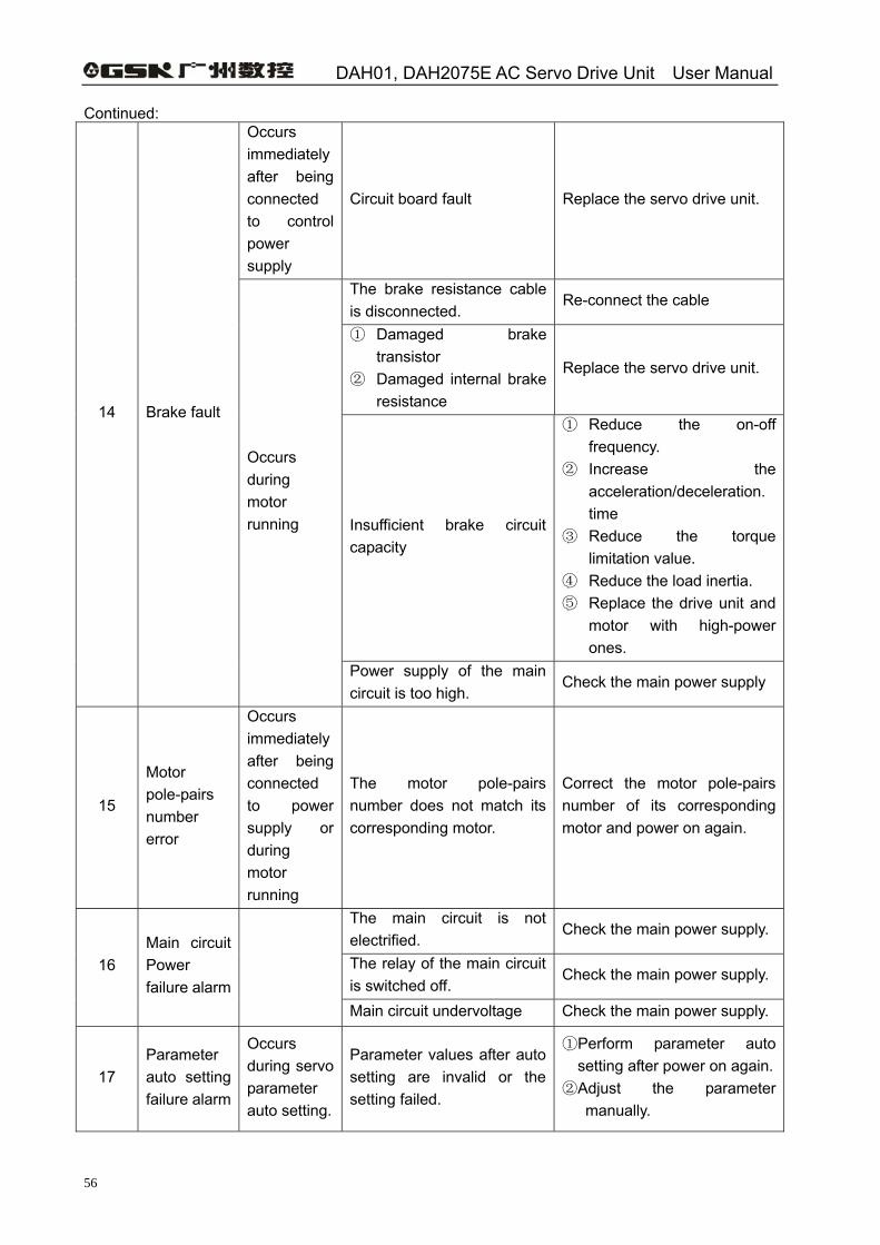
DAH01, DAH2075E AC Servo Drive Unit User Manual
56
Continued: Occurs immediately after being connected to control power supply
Circuit board fault Replace the servo drive unit.
The brake resistance cable is disconnected.
Re-connect the cable
① Damaged brake transistor
② Damaged internal brake resistance
Replace the servo drive unit.
Insufficient brake circuit capacity
① Reduce the on-off frequency.
② Increase the acceleration/deceleration. time
③ Reduce the torque limitation value.
④ Reduce the load inertia. ⑤ Replace the drive unit and
motor with high-power ones.
14 Brake fault
Occurs during motor running
Power supply of the main circuit is too high.
Check the main power supply
15
Motor pole-pairs number error
Occurs immediately after being connected to power supply or during motor running
The motor pole-pairs number does not match its corresponding motor.
Correct the motor pole-pairs number of its corresponding motor and power on again.
The main circuit is not electrified.
Check the main power supply.
The relay of the main circuit is switched off.
Check the main power supply. 16 Main circuit Power failure alarm
Main circuit undervoltage Check the main power supply.
17 Parameter auto setting failure alarm
Occurs during servo parameter auto setting.
Parameter values after auto setting are invalid or the setting failed.
①Perform parameter auto setting after power on again.
②Adjust the parameter manually.
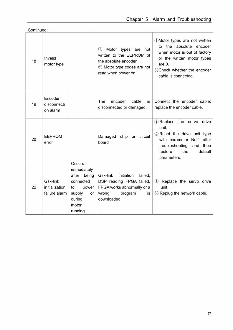
Chapter 5 Alarm and Troubleshooting
57
Continued:
18 Invalid motor type
① Motor types are not written to the EEPROM of the absolute encoder. ② Motor type codes are not read when power on.
①Motor types are not written to the absolute encoder when motor is out of factory or the written motor types are 0.
②Check whether the encoder cable is connected.
19 Encoder disconnection alarm
The encoder cable is disconnected or damaged.
Connect the encoder cable; replace the encoder cable.
20 EEPROM error
Damaged chip or circuit board
① Replace the servo drive unit.
② Reset the drive unit type with parameter No.1 after troubleshooting, and then restore the default parameters.
22 Gsk-link initialization failure alarm
Occurs immediately after being connected to power supply or during motor running
Gsk-link initiation failed, DSP reading FPGA failed, FPGA works abnormally or a wrong program is downloaded.
① Replace the servo drive unit.
② Replug the network cable.
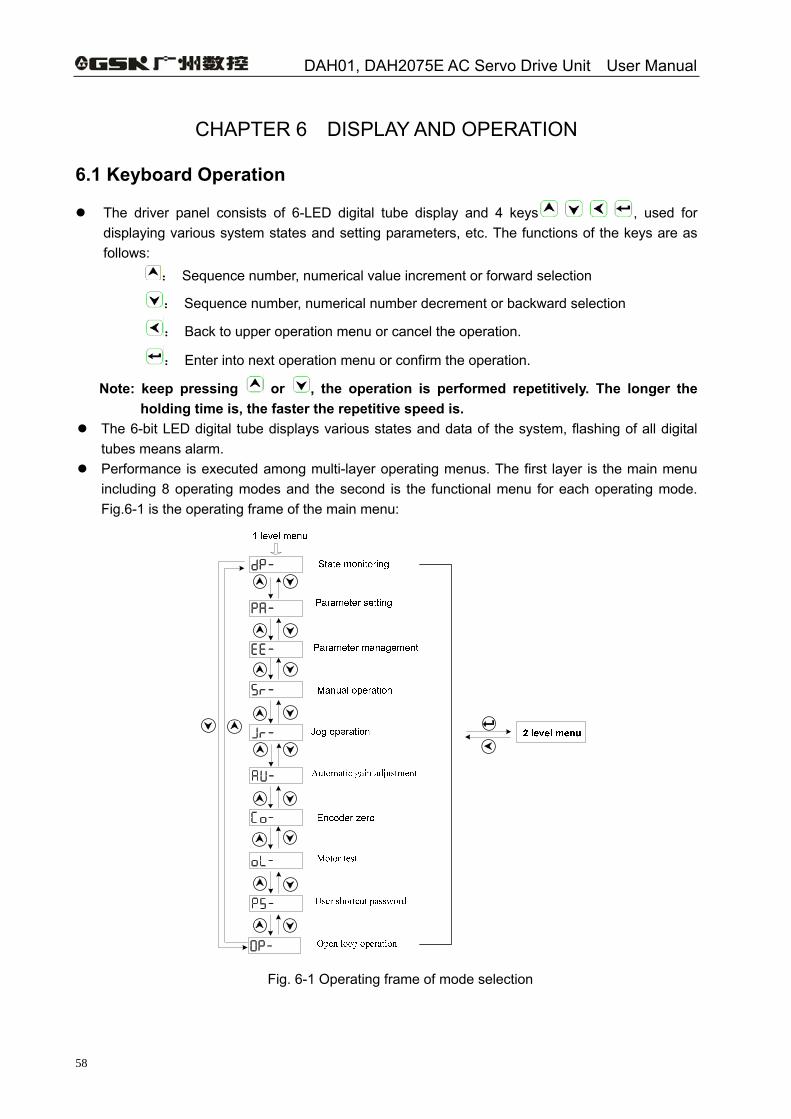
DAH01, DAH2075E AC Servo Drive Unit User Manual
58
CHAPTER 6 DISPLAY AND OPERATION
6.1 Keyboard Operation
The driver panel consists of 6-LED digital tube display and 4 keys , used for displaying various system states and setting parameters, etc. The functions of the keys are as follows:
: Sequence number, numerical value increment or forward selection
: Sequence number, numerical number decrement or backward selection
: Back to upper operation menu or cancel the operation.
: Enter into next operation menu or confirm the operation.
Note: keep pressing or , the operation is performed repetitively. The longer the holding time is, the faster the repetitive speed is.
The 6-bit LED digital tube displays various states and data of the system, flashing of all digital tubes means alarm.
Performance is executed among multi-layer operating menus. The first layer is the main menu including 8 operating modes and the second is the functional menu for each operating mode. Fig.6-1 is the operating frame of the main menu:
Fig. 6-1 Operating frame of mode selection
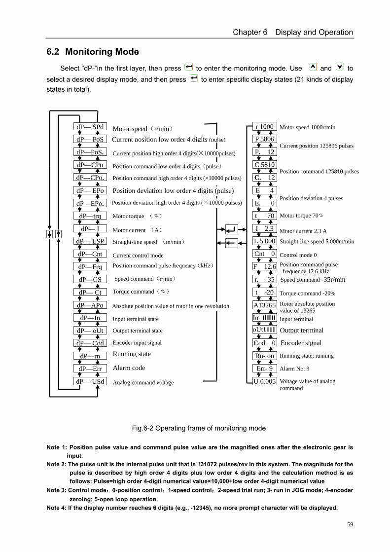
Chapter 6 Display and Operation
59
6.2 Monitoring Mode
Select “dP-“in the first layer, then press to enter the monitoring mode. Use and to select a desired display mode, and then press to enter specific display states (21 kinds of display states in total).
Fig.6-2 Operating frame of monitoring mode
Note 1: Position pulse value and command pulse value are the magnified ones after the electronic gear is
input. Note 2: The pulse unit is the internal pulse unit that is 131072 pulses/rev in this system. The magnitude for the
pulse is described by high order 4 digits plus low order 4 digits and the calculation method is as follows: Pulse=high order 4-digit numerical value×10,000+low order 4-digit numerical value
Note 3: Control mode:0-position control;1-speed control;2-speed trial run; 3- run in JOG mode; 4-encoder zeroing; 5-open loop operation.
Note 4: If the display number reaches 6 digits (e.g., -12345), no more prompt character will be displayed.
Rotor absolute position value of 13265
dP— SPd r 1000
dP— PoS
dP—PoS.
dP—CPo
dP—CPo.
dP— EPo
dP—EPo.
dP—trq
dP— I
dP— LSP
dP—Cnt
dP—Frq
dP—CS
dP— Ct
dP—APo
dP—In
dP— oUt
dP— Cod
dP—rn
dP—Err
dP— USd
Position deviation low order 4 digits (pulse)
Position deviation high order 4 digits (×10000 pulses)
)
Running state
Alarm code
P 5806
P. 12
C 5810
C. 12
E 4
E. 0
t 70
I 2.3
L 5.000
Cnt 0
F 12.6
r. -35
t -20
A13265
Cod 0
Rn- on
Err- 9
U 0.005
Output terminal
Encoder signal
oUt
In
Position command pulse frequency 12.6 kHz Speed command -35r/min
Motor speed(r/min) Current position low order 4 digits (pulse)
Current position high order 4 digits(×10000pulses)
Position command low order 4 digits(pulse)
Position command high order 4 digits (×10000 pulses)
Motor torque (﹪)
Motor current (A)
Straight-line speed (m/min)
Current control mode
Position command pulse frequency(kHz)
Speed command(r/min)
Torque command(﹪)
Absolute position value of rotor in one revolution
Input terminal state
Output terminal state
Encoder input signal
Analog command voltage
Motor speed 1000r/min
Current position 125806 pulses
Position command 125810 pulses
Position deviation 4 pulses
Motor torque 70﹪
Motor current 2.3 A
Straight-line speed 5.000m/min
Control mode 0
Speed command -35r/min
Torque command -20%
Input terminal
Running state: running
Alarm No. 9
Voltage value of analog command
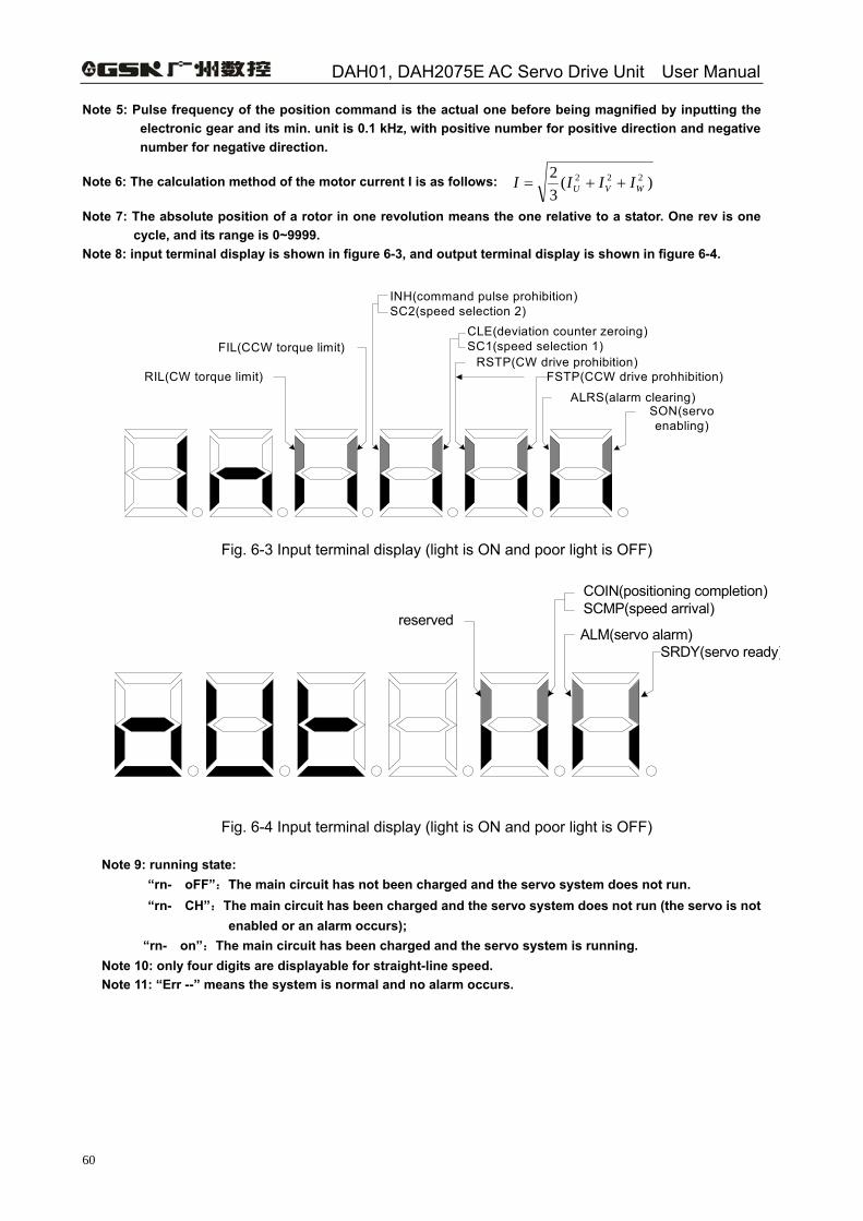
DAH01, DAH2075E AC Servo Drive Unit User Manual
60
Note 5: Pulse frequency of the position command is the actual one before being magnified by inputting the electronic gear and its min. unit is 0.1 kHz, with positive number for positive direction and negative number for negative direction.
Note 6: The calculation method of the motor current I is as follows: )(32 222
WVU IIII ++=
Note 7: The absolute position of a rotor in one revolution means the one relative to a stator. One rev is one cycle, and its range is 0~9999.
Note 8: input terminal display is shown in figure 6-3, and output terminal display is shown in figure 6-4.
SON(servo enabling)
RSTP(CW drive prohibition)
CLE(deviation counter zeroing)SC1(speed selection 1)FIL(CCW torque limit)
FSTP(CCW drive prohhibition)
ALRS(alarm clearing)
INH(command pulse prohibition)SC2(speed selection 2)
RIL(CW torque limit)
Fig. 6-3 Input terminal display (light is ON and poor light is OFF)
SRDY(servo ready)
reserved
COIN(positioning completion)SCMP(speed arrival)
ALM(servo alarm)
Fig. 6-4 Input terminal display (light is ON and poor light is OFF)
Note 9: running state: “rn- oFF”:The main circuit has not been charged and the servo system does not run. “rn- CH”:The main circuit has been charged and the servo system does not run (the servo is not
enabled or an alarm occurs); “rn- on”:The main circuit has been charged and the servo system is running.
Note 10: only four digits are displayable for straight-line speed. Note 11: “Err --” means the system is normal and no alarm occurs.
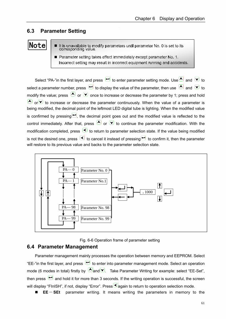
Chapter 6 Display and Operation
61
6.3 Parameter Setting
Note
Select “PA-”in the first layer, and press to enter parameter setting mode. Use and to
select a parameter number, press to display the value of the parameter, then use and to
modify the value; press or once to increase or decrease the parameter by 1; press and hold
or to increase or decrease the parameter continuously. When the value of a parameter is being modified, the decimal point of the leftmost LED digital tube is lighting. When the modified value
is confirmed by pressing , the decimal point goes out and the modified value is reflected to the
control immediately. After that, press or to continue the parameter modification. With the
modification completed, press to return to parameter selection state. If the value being modified
is not the desired one, press to cancel it instead of pressing to confirm it, then the parameter will restore to its previous value and backs to the parameter selection state.
Fig. 6-6 Operation frame of parameter setting
6.4 Parameter Management Parameter management mainly processes the operation between memory and EEPROM. Select
“EE-”in the first layer, and press to enter into parameter management mode. Select an operation
mode (6 modes in total) firstly by and . Take Parameter Writing for example: select “EE-Set”,
then press and hold it for more than 3 seconds. If the writing operation is successful, the screen
will display “FInISH”, if not, display “Error”. Press again to return to operation selection mode. EE-SEt parameter writing. It means writing the parameters in memory to the
PA— 0
PA— 1
PA— 98
PA— 99
. 1000
Parameter No. 0
Parameter No.1
Parameter No. 98
Parameter No. 99
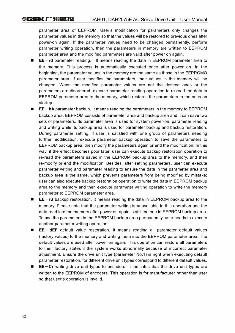
DAH01, DAH2075E AC Servo Drive Unit User Manual
62
parameter area of EEPROM. User’s modification for parameters only changes the parameter values in the memory so that the values will be restored to previous ones after power-on again. If the parameter values need to be changed permanently, perform parameter writing operation, then the parameters in memory are written to EEPROM parameter area and the modified parameters are valid after power on again.
EE-rd parameter reading. It means reading the data in EEPROM parameter area to the memory. This process is automatically executed once after power on. In the beginning, the parameter values in the memory are the same as those in the EEPROMO parameter area. If user modifies the parameters, their values in the memory will be changed. When the modified parameter values are not the desired ones or the parameters are disordered, execute parameter reading operation to re-read the data in EEPROM parameter area to the memory, which restores the parameters to the ones on startup.
EE-bA parameter backup. It means reading the parameters in the memory to EEPROM backup area. EEPROM consists of parameter area and backup area and it can save two sets of parameters. Its parameter area is used for system power-on, parameter reading and writing while its backup area is used for parameter backup and backup restoration. During parameter setting, if user is satisfied with one group of parameters needing further modification, execute parameter backup operation to save the parameters to EEPROM backup area, then modify the parameters again or end the modification. In this way, if the effect becomes poor later, user can execute backup restoration operation to re-read the parameters saved in the EEPROM backup area to the memory, and then re-modify or end the modification. Besides, after setting parameters, user can execute parameter writing and parameter reading to ensure the data in the parameter area and backup area is the same, which prevents parameters from being modified by mistake; user can also execute backup restoration operation to write the data in EEPROM backup area to the memory and then execute parameter writing operation to write the memory parameter to EEPROM parameter area.
EE-rS backup restoration. It means reading the data in EEPROM backup area to the memory. Please note that the parameter writing is unavailable in this operation and the data read into the memory after power on again is still the one in EEPROM backup area. To use the parameters in the EEPROM backup area permanently, user needs to execute another parameter writing operation.
EE-dEF default value restoration. It means reading all parameter default values (factory values) to the memory and writing them into the EEPROM parameter area. The default values are used after power on again. This operation can restore all parameters to their factory states if the system works abnormally because of incorrect parameter adjustment. Ensure the drive unit type (parameter No.1) is right when executing default parameter restoration, for different drive unit types correspond to different default values.
EE-Cr writing drive unit types to encoders. It indicates that the drive unit types are written to the EEPROM of encoders. This operation is for manufacturer rather than user so that user’s operation is invalid.
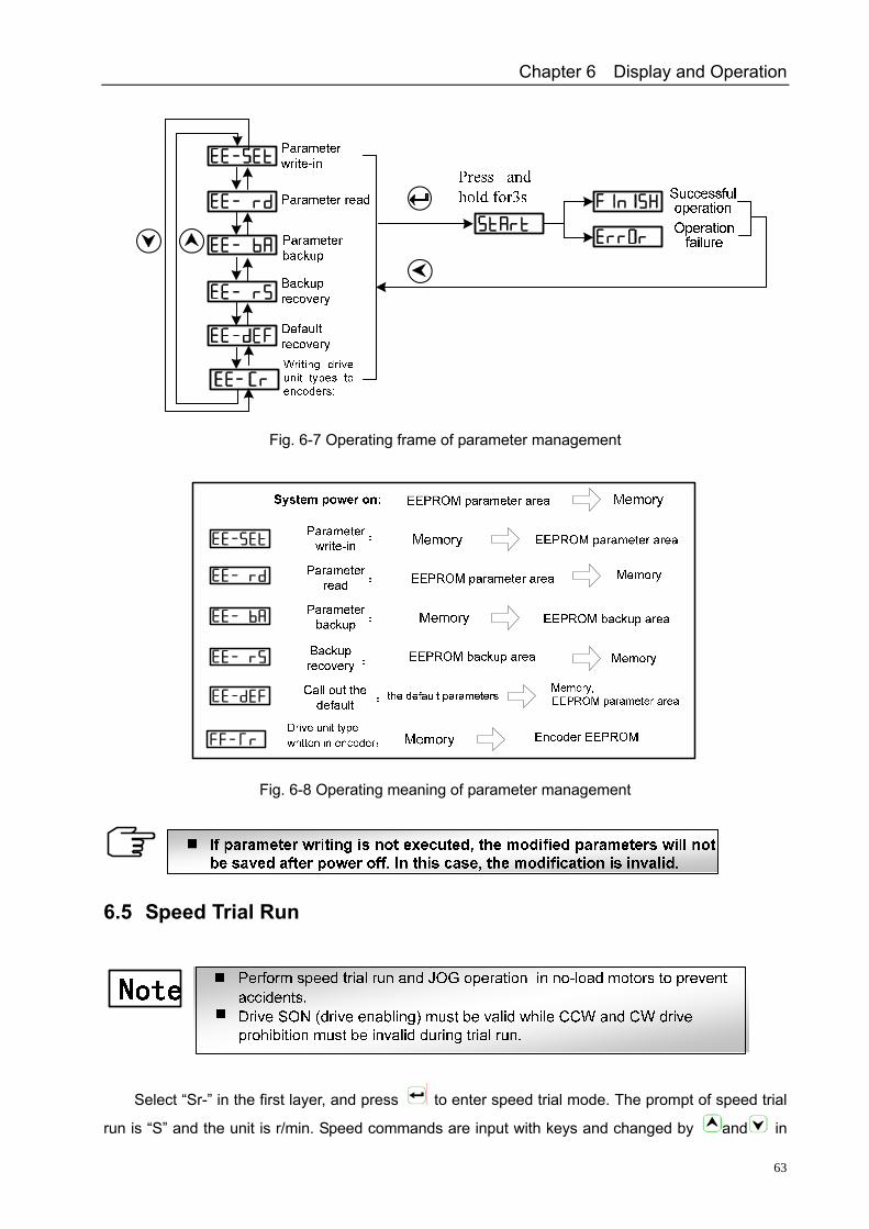
Chapter 6 Display and Operation
63
Fig. 6-7 Operating frame of parameter management
Fig. 6-8 Operating meaning of parameter management
6.5 Speed Trial Run
Select “Sr-” in the first layer, and press to enter speed trial mode. The prompt of speed trial
run is “S” and the unit is r/min. Speed commands are input with keys and changed by and in
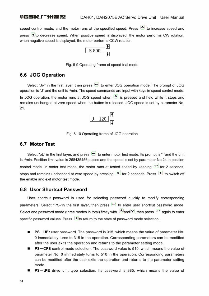
DAH01, DAH2075E AC Servo Drive Unit User Manual
64
speed control mode, and the motor runs at the specified speed. Press to increase speed and
press to decrease speed. When positive speed is displayed, the motor performs CW rotation; when negative speed is displayed, the motor performs CCW rotation.
Fig. 6-9 Operating frame of speed trial mode
6.6 JOG Operation
Select “Jr-” in the first layer, then press to enter JOG operation mode. The prompt of JOG operation is “J” and the unit is r/min. The speed commands are input with keys in speed control mode.
In JOG operation, the motor runs at JOG speed when is pressed and held while it stops and remains unchanged at zero speed when the button is released. JOG speed is set by parameter No. 21.
Fig. 6-10 Operating frame of JOG operation
6.7 Motor Test
Select “oL” in the first layer, and press to enter motor test mode. Its prompt is “r”and the unit is r/min. Position limit value is 268435456 pulses and the speed is set by parameter No.24 in position
control mode. In motor test mode, the motor runs at tested speed by keeping for 2 seconds,
stops and remains unchanged at zero speed by pressing for 2 seconds. Press to switch off the enable and exit motor test mode.
6.8 User Shortcut Password User shortcut password is used for selecting password quickly to modify corresponding
parameters. Select “PS-”in the first layer, then press to enter user shortcut password mode.
Select one password mode (three modes in total) firstly with and , then press again to enter
specific password values. Press to return to the state of password mode selection.
PS-UEr user password. The password is 315, which means the value of parameter No.
0 immediately turns to 315 in the operation. Corresponding parameters can be modified after the user exits the operation and returns to the parameter setting mode.
PS-CFS control mode selection. The password value is 510, which means the value of parameter No. 0 immediately turns to 510 in the operation. Corresponding parameters can be modified after the user exits the operation and returns to the parameter setting mode.
PS-tPE drive unit type selection. Its password is 385, which means the value of
S 800
J 120
Chapter 6 Display and Operation
65
parameter No. 0 immediately turns to 385 in the operation. Corresponding parameters can be modified after the user exits the operation and returns to the parameter setting mode.
6.9 Servo Parameter Auto Setting The parameter auto setting newly developed by our company can identify system control models
accurately, and find out a group of optimal parameters for servo control automatically and quickly according to different load inertia ratios. Compared with the manual setting for PID parameters, it saves lots of time and energy and has strong adaptability. Its operation procedures are as follows:
① After power supply is connected correctly, the upper computer starts to send enable signal to the servo drive unit and the signal remains enabled. When connecting the closed-loop system (CNC), shield the alarm of system (CNC) position deviation.
② Select “Au”in the first layer, press and hold for 3 seconds to enter auto setting mode of servo parameters. It is normal to see ±0.5 pitch oscillating back and forth on the machine at the moment. If the auto setting succeeds, the screen will display “FInISH”. The changes of
parameter No.5 and No.6 can be checked by returning to “PA” with . If another auto setting is needed, repeat procedure 2. If the auto setting fails, the screen will display “Err-17” (i.e., alarm No.17).
③ After the successful parameter auto setting, the set parameters are saved to the E2PROM storage location of the servo drive unit automatically and take effect immediately without power on again; if the set parameters are not the optimal ones, operators can fine tune the values of parameter No.5 and No.6. Please note that the parameters cannot be saved automatically at the moment, so parameter management “EE-SET” needs to be performed to save them. Refer to 6.4 for details.
6.10 Others On-line adjustment for automatic gains is not provided currently, for it is under development. Encoder zeroing function is for motor manufacturer, please do not use it. Open-loop operation mode is for motor manufacturer, please do not use it.
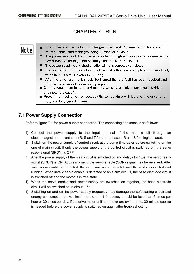
DAH01, DAH2075E AC Servo Drive Unit User Manual
66
CHAPTER 7 RUN
Note
7.1 Power Supply Connection Refer to figure 7-1 for power supply connection. The connecting sequence is as follows: 1) Connect the power supply to the input terminal of the main circuit through an
electromagnetism contactor (R, S and T for three phases, R and S for single phase). 2) Switch on the power supply of control circuit at the same time as or before switching on the
one of main circuit. If only the power supply of the control circuit is switched on, the servo ready signal (SRDY) is OFF.
3) After the power supply of the main circuit is switched on and delays for 1.5s, the servo ready signal (SRDY) is ON. At this moment, the servo enable (SON) signal may be received. After valid servo enable is detected, the drive unit output is valid, and the motor is excited and running. When invalid servo enable is detected or an alarm occurs, the base electrode circuit is switched off and the motor is in free state.
4) When the servo enable and power supply are switched on together, the base electrode circuit will be switched on in about 1.5s.
5) Switching on and off the power supply frequently may damage the soft-starting circuit and energy consumption brake circuit, so the on-off frequency should be less than 5 times per hour or 30 times per day. If the drive motor unit and motor are overheated, 30-minute cooling is needed before the power supply is switched on again after troubleshooting.
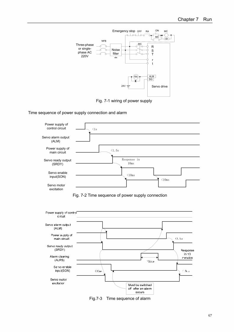
Chapter 7 Run
67
RST
rt
Three-phase or single-phase AC
220V
NFBMC
Servo drive
SK
ON
MC
RAOFFEmergency stop
RA ALMDG
24V
Noise filter
MC
Fig. 7-1 wiring of power supply
Time sequence of power supply connection and alarm
Power supply of
control circuit
Servo alarm output (ALM)
Power supply of main circuit
Servo ready output (SRDY)
Servo enable input(SON)
Servo motor excitation
<1s
<1.5s
Response in 10ms
<10ms
<10ms
Fig. 7-2 Time sequence of power supply connection
Fig.7-3 Time sequence of alarm
DAH01, DAH2075E AC Servo Drive Unit User Manual
68
7.2 Trial Run 1) Check before running
Check the following items before power on after installation and wiring: Whether the TB wiring of the power supply and reliable input voltage are correct Whether the power line and motor line are short circuited or grounded Whether the connection of encoder cables is correct. Whether the connection of the control signal terminal and the polarity as well as the size of
the power supply are correct. Whether the drive unit and motor are fixed tightly. Whether the motor shaft is connected to the load.
2) Trial run after power on (1) Trial run mode ① Connect to CN1 to make servo enable (SON) OFF, CCW drive prohibition (FSTP) ON
and CW drive prohibition (RSTP) ON. ② Please check the wiring if an alarm occurs after the power supply of the control circuit
(no connection for main circuit) is connected and the display of the drive unit is switched on.
③ Set the control mode selection (parameter No.4) to the speed trial run mode (set to 2). ④ Switch on the power supply of the main circuit. ⑤ After confirming that no alarm or abnormality occurs, make the servo enable (SON) ON.
Then the motor is excited and in zero seed state. ⑥ Press keys to enter speed trial mode. Its prompt is “S“and the unit is r/min. When the
system is in speed control mode, speed commands are input by keys. Press and to change the commands, then the motor runs at the specified speed.
(2) JOG run ① Connect to CN1 to make servo enable (SON) OFF, CCW drive prohibition (FSTP) ON
and CW drive prohibition (RSTP) ON. ② Please check the wiring if an alarm occurs after the power supply of control circuit (no
connection for main circuit) is connected and the display of the drive unit is switched on. ③ Set the control mode selection (parameter No.4) to JOG mode (set to 3). ④ Switch on the power supply of main circuit. ⑤ If there is no alarm or abnormality, make the servo enable (SON) ON. Then the motor is
excited and in zero seed state. ⑥ Press keys to enter JOG run mode. The prompt and unit of the mode are “J” and r/min
respectively. When the system is in the speed control mode, the speed and direction are decided by parameter No. 21. Press to make the motor run at the speed and in the direction decided by No.21, while press to make the motor run in negative direction at specified speed.
(3)Position control mode operation ① Connect to CN1 to make servo enable (SON) OFF, CCW drive prohibition (FSTP) ON
and CW drive prohibition (RSTP) ON. ② Please check the wiring if an alarm occurs after the power supply of control circuit (no
connection for main circuit) is connected and the display of drive unit is switched on. ③ Set the control mode selection (parameter No.4) to position running mode (set to 0). Set
Chapter 7 Run
69
parameter No.14 and electronic gear ratio (No.12,No.13)according to controller output signal mode.
④ Switch on the power supply of the main circuit. ⑤ If there is no alarm or abnormality, make the servo enable (SON) ON. At this moment,
the motor is excited and in zero-speed state. ⑥ Operate the position controller to output signals to drive pins CN1-6, CN1-18, CN1-7 and
CN1-19, making the motor runs according to commands.
(4)Speed control mode operation The speed operation mode consists of the speed control of external analog voltage and the
speed control of internal speed.
Speed control mode of external analog voltage: ① Connect to CN1 to make servo enable (SON) ON, CCW drive prohibition (FSTP) ON, CW
drive prohibition (RSTP) ON. ② Please check the wiring if an alarm occurs after the power supply of the control circuit (no
connection for main circuit) is connected and the display of the drive unit is switched on. ③ Set the control mode selection (parameter No.4) to the speed running mode (set to 1), and
set parameter No. 43 to 1. ④ Switch on the power supply of the main circuit. ⑤ If there is no alarm or abnormality, make the servo enable (SON) ON. At this moment, the
motor is excited and in the running state that the speed is controlled by the external analog voltage.
Analog speed zeroing: 1) Set PA49 to 1;
2) Shift the display to”DP-SPD”; 3) Observe the current speed: If the direction is clockwise, adjust
the value of PA44 to a bigger one; if the direction is counterclockwise, adjust the value to a smaller one till the speed is displayed as”R-0”.
4) Set parameter No.49 to 0; 5) Shift the display to”DP-POS”; 6) Observe the current position: if it is increasing, adjust the value of
PA45 to a bigger one, if it is decreasing, adjust the value to a smaller one till the position value is stable.
⑥ Chang the external analog voltage to change the motor speed, and change the direction of
the analog voltage to change the rotation direction of the motor Note: In speed control mode, even if the analog command voltage sends 0V command, the motor will still
rotates at very low speed. At this moment, it needs to adjust the amplifier zero.
Two kinds of internal speed control: ① Connect CN1 to make servo enable (SON) OFF, speed selection (SC1) OFF, speed selection
2 (SC2) OFF, CCW drive prohibition (FSTP) ON and CW drive prohibition (RSTP) ON. ② Please check the wiring if an alarm occurs after the power supply of the control circuit (no
connection for main circuit) is connected and the display of the drive unit is switched on.
DAH01, DAH2075E AC Servo Drive Unit User Manual
70
③Set the control mode selection (parameter No.4) to the speed running mode (set to 1), and set parameter No. 43 to 0. In addition, set speed parameter No.24~No.27as needed.
④ Switch on the power supply of the main circuit. ⑤If there is no alarm or abnormality, make servo enable (SON) ON. At this moment, the motor is
excited and runs at internal speed 1. ⑥Change the state of input signals SC1 and SC2 to make the motor run at the specified speed.
7.3 Adjustment
Note
1)Basic gain adjustment (1)Speed control
① The setting value of [speed proportional gain] (parameter No. 5): the value should be set as big as possible under the condition of no vibration. In general, the bigger the load inertia is, the bigger the value is.
②The setting value of [speed integration time constant] (parameter No.6): the value should be as small as possible according to given conditions. If the value is too small, the response speed will increase, but vibration will occur too. Therefore, set the value as small as possible under the condition of no vibration. If the value is too big, the speed may change significantly with the load.
(2)Position control ① Set proper [speed proportion gain] and [speed integration time constant] following the above
methods. ② Set [position feedforward gain] (parameter No. 10) to 0%. ③The setting value of [position proportion gain] (parameter No.9): the value should be set as big
as possible within a stable range. A too big value leads to good track characteristics of position commands and small lag error, but also causes vibration easily when the positioning is stopped.
④Increase the setting value of [position feedforward gain] if particularly high position track characteristics are needed, but an extremely big value will cause overshoot.
Note: a small setting value of the position proportion gain leads to a stable state for the system, but also causes bad position track and big lag error.
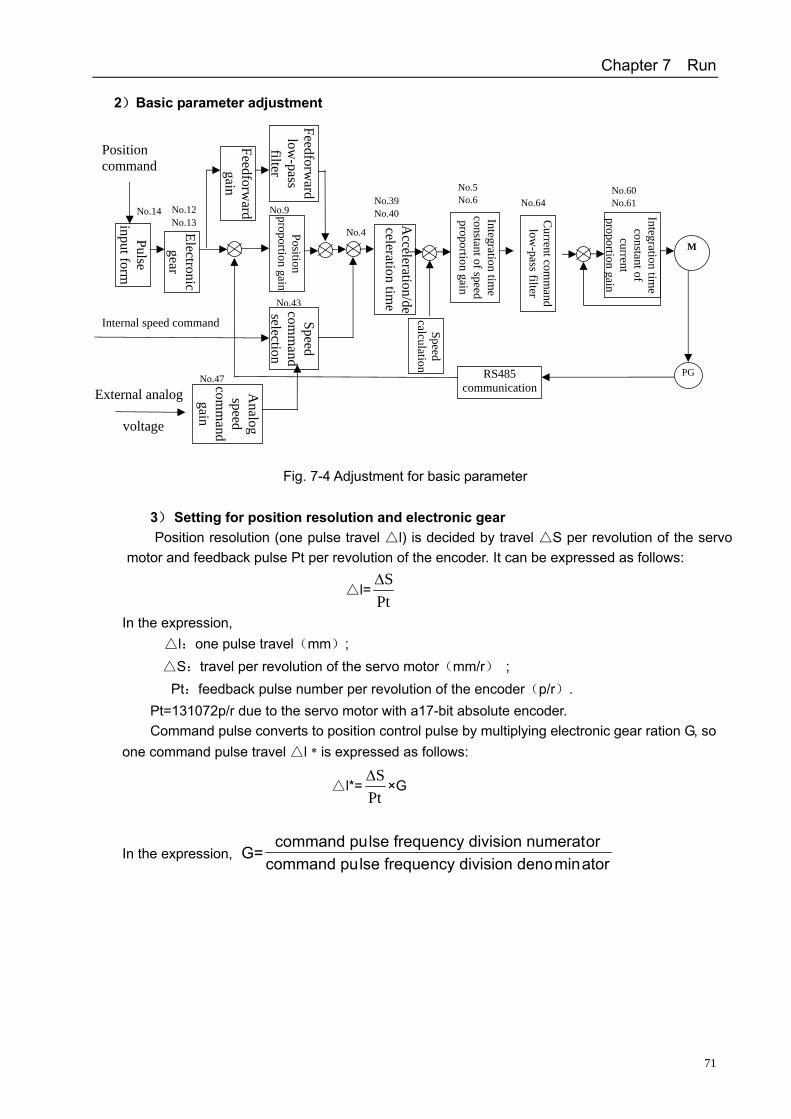
Chapter 7 Run
71
2)Basic parameter adjustment
Fig. 7-4 Adjustment for basic parameter
3) Setting for position resolution and electronic gear Position resolution (one pulse travel l) is decided by travel S per revolution of the servo
motor and feedback pulse Pt per revolution of the encoder. It can be expressed as follows:
l=PtSΔ
In the expression, l:one pulse travel(mm); S :travel per revolution of the servo motor(mm/r) ;
Pt:feedback pulse number per revolution of the encoder(p/r). Pt=131072p/r due to the servo motor with a17-bit absolute encoder. Command pulse converts to position control pulse by multiplying electronic gear ration G, so
one command pulse travel l﹡is expressed as follows:
l*=PtSΔ
×G
In the expression, atorminon denoncy divisilse frequecommand puoron numeratncy divisilse frequecommand pu
G=
Pulse input form
Electronic gear
Speed calculation
Position proportion gain
Feedforward
gain
Feedforward
low-pass
filte r
Acceleration/de
celeration time
Integration time
constant of speed proportion gain
Current com
mand
low-pass filter
Integration time
constant of current
proportion gain
Speed com
mand
selectionA
nalog speed
comm
andgain
RS485 communication
M
PG
Position command
Internal speed command
External analog
voltage
No.14 No.12 No.13
No.39No.40
No.5No.6
No.60 No.61 No.64
No.4
No.43
No.47
No.9
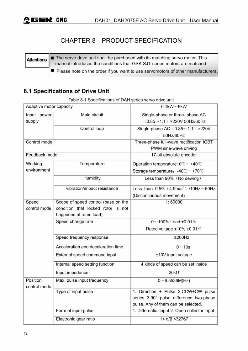
DAH01, DAH2075E AC Servo Drive Unit User Manual
72
CHAPTER 8 PRODUCT SPECIFICATION
The servo drive unit shall be purchased with its matching servo motor. This manual introduces the conditions that GSK SJT series motors are matched.
Attentions
Please note on the order if you want to use servomotors of other manufacturers.
8.1 Specifications of Drive Unit Table 8-1 Specifications of DAH series servo drive unit
Adaptive motor capacity 0.1kW~6kW
Main circuit Single-phase or three- phase AC (0.85~1.1)×220V 50Hz/60Hz
Input power supply
Control loop Single-phase AC(0.85~1.1)×220V 50Hz/60Hz
Control mode Three-phase full-wave rectification IGBT PWM sine-wave driving
Feedback mode 17-bit absolute encoder
Temperature Operation temperature: 0~+40 Storage temperature:-40~+70
Humidity Less than 90%(No dewing)
Working environment
vibration/impact resistance Less than 0.5G(4.9m/s2)/10Hz~60Hz (Discontinuous movement)
Scope of speed control (base on the condition that locked rotor is not happened at rated load)
1: 60000
Speed change rate 0~100% Load:±0.01﹪ Rated voltage ±10%:±0.01﹪
Speed frequency response ≥200Hz
Acceleration and deceleration time 0~10s
External speed command input ±10V input voltage
Internal speed setting function 4 kinds of speed can be set inside
Speed control mode
Input impedance 20kΩ
Max. pulse input frequency 0~6.5536M(Hz)
Type of input pulse 1. Direction + Pulse 2.CCW+CW pulse series 3.90° pulse difference two-phase pulse. Any of them can be selected.
Form of input pulse 1. Differential input 2. Open collector input
Position control mode
Electronic gear ratio 1< α/β <32767
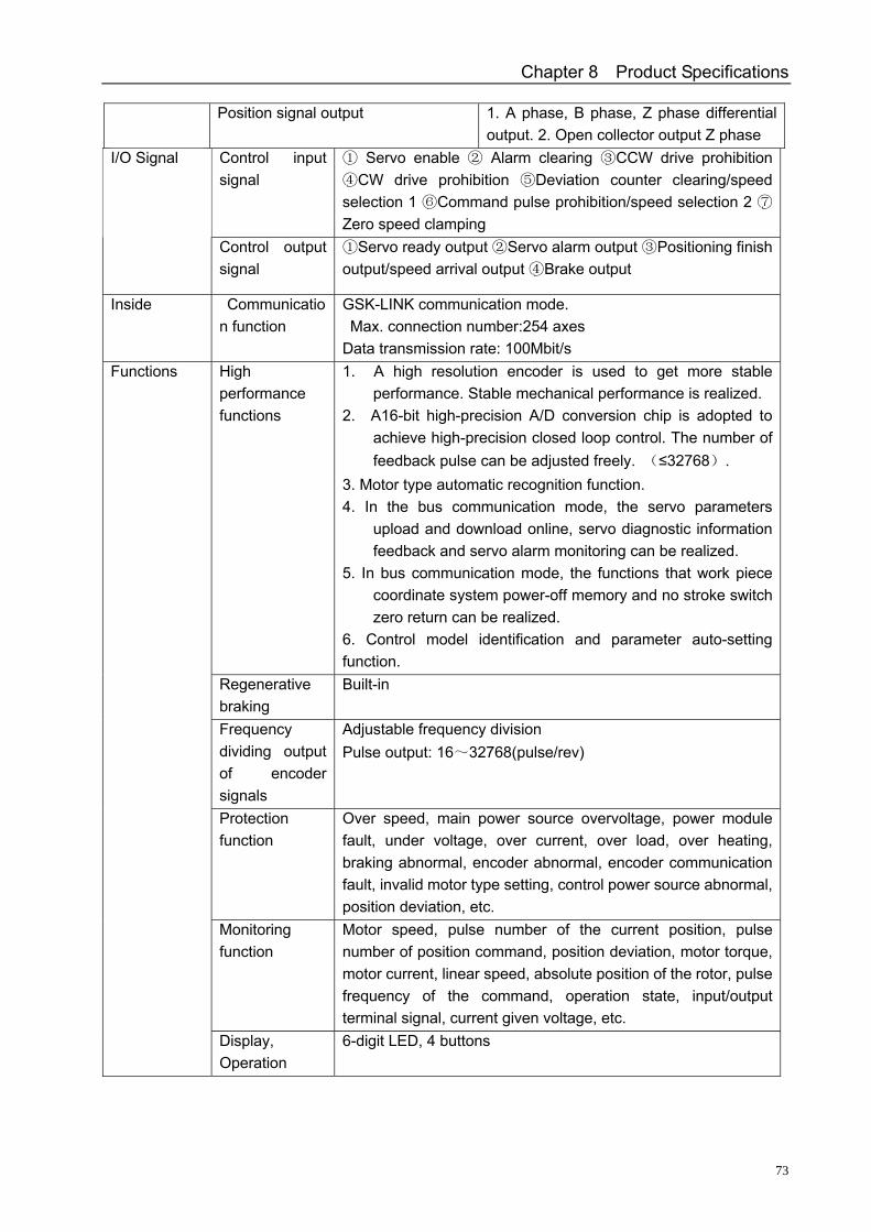
Chapter 8 Product Specifications
73
Position signal output 1. A phase, B phase, Z phase differential output. 2. Open collector output Z phase
Control input signal
Servo enable Alarm clearing ① ② ③CCW drive prohibition CW drive prohibition Deviation counter clearing/speed ④ ⑤
selection 1 Command pulse prohibition/speed selection 2 ⑥ ⑦
Zero speed clamping
I/O Signal
Control output signal
Servo ready output Servo alarm output Positioning finish ① ② ③
output/speed arrival output Brake output④
Inside Communication function
GSK-LINK communication mode. Max. connection number:254 axes Data transmission rate: 100Mbit/s
High performance functions
1. A high resolution encoder is used to get more stable performance. Stable mechanical performance is realized.
2. A16-bit high-precision A/D conversion chip is adopted to achieve high-precision closed loop control. The number of feedback pulse can be adjusted freely. (≤32768).
3. Motor type automatic recognition function. 4. In the bus communication mode, the servo parameters
upload and download online, servo diagnostic information feedback and servo alarm monitoring can be realized.
5. In bus communication mode, the functions that work piece coordinate system power-off memory and no stroke switch zero return can be realized.
6. Control model identification and parameter auto-setting function.
Regenerative braking
Built-in
Frequency dividing output of encoder signals
Adjustable frequency division Pulse output: 16~32768(pulse/rev)
Protection function
Over speed, main power source overvoltage, power module fault, under voltage, over current, over load, over heating, braking abnormal, encoder abnormal, encoder communication fault, invalid motor type setting, control power source abnormal, position deviation, etc.
Monitoring function
Motor speed, pulse number of the current position, pulse number of position command, position deviation, motor torque, motor current, linear speed, absolute position of the rotor, pulse frequency of the command, operation state, input/output terminal signal, current given voltage, etc.
Functions
Display, Operation
6-digit LED, 4 buttons
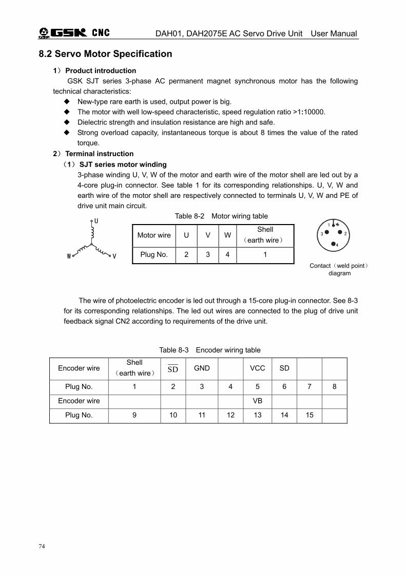
DAH01, DAH2075E AC Servo Drive Unit User Manual
74
8.2 Servo Motor Specification 1) Product introduction
GSK SJT series 3-phase AC permanent magnet synchronous motor has the following technical characteristics:
New -type rare earth is used, output power is big. The motor with well low -speed characteristic, speed regulation ratio >1:10000. Dielectric strength and insulation resistance are high and safe. Strong overload capacity, instantaneous torque is about 8 times the value of the rated
torque. 2) Terminal instruction (1) SJT series motor winding
3-phase winding U, V, W of the motor and earth wire of the motor shell are led out by a 4-core plug-in connector. See table 1 for its corresponding relationships. U, V, W and earth wire of the motor shell are respectively connected to terminals U, V, W and PE of drive unit main circuit.
Table 8-2 Motor wiring table
The wire of photoelectric encoder is led out through a 15-core plug-in connector. See 8-3
for its corresponding relationships. The led out wires are connected to the plug of drive unit feedback signal CN2 according to requirements of the drive unit.
Table 8-3 Encoder wiring table
Motor wire U V WShell
(earth wire)
Plug No. 2 3 4 1
Encoder wire Shell
(earth wire) SD GND VCC SD
Plug No. 1 2 3 4 5 6 7 8
Encoder wire VB
Plug No. 9 10 11 12 13 14 15
4
3
1
2
W V
U
Contact(weld point)diagram
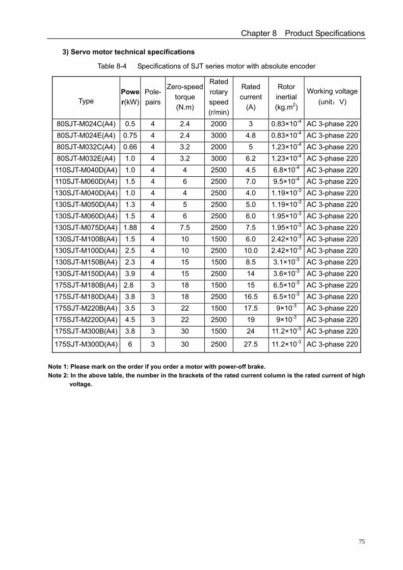
Chapter 8 Product Specifications
75
3) Servo motor technical specifications
Table 8-4 Specifications of SJT series motor with absolute encoder
Type Power(kW)
Pole-pairs
Zero-speed torque (N.m)
Rated rotary speed(r/min)
Rated current
(A)
Rotor inertial (kg.m2)
Working voltage(unit:V)
80SJT-M024C(A4) 0.5 4 2.4 2000 3 0.83×10⁻⁴ AC 3-phase 22080SJT-M024E(A4) 0.75 4 2.4 3000 4.8 0.83×10⁻⁴ AC 3-phase 22080SJT-M032C(A4) 0.66 4 3.2 2000 5 1.23×10⁻⁴ AC 3-phase 22080SJT-M032E(A4) 1.0 4 3.2 3000 6.2 1.23×10⁻⁴ AC 3-phase 220110SJT-M040D(A4) 1.0 4 4 2500 4.5 6.8×10⁻⁴ AC 3-phase 220110SJT-M060D(A4) 1.5 4 6 2500 7.0 9.5×10⁻⁴ AC 3-phase 220130SJT-M040D(A4) 1.0 4 4 2500 4.0 1.19×10⁻³ AC 3-phase 220130SJT-M050D(A4) 1.3 4 5 2500 5.0 1.19×10⁻³ AC 3-phase 220130SJT-M060D(A4) 1.5 4 6 2500 6.0 1.95×10⁻³ AC 3-phase 220130SJT-M075D(A4) 1.88 4 7.5 2500 7.5 1.95×10⁻³ AC 3-phase 220130SJT-M100B(A4) 1.5 4 10 1500 6.0 2.42×10⁻³ AC 3-phase 220130SJT-M100D(A4) 2.5 4 10 2500 10.0 2.42×10⁻³ AC 3-phase 220130SJT-M150B(A4) 2.3 4 15 1500 8.5 3.1×10⁻³ AC 3-phase 220130SJT-M150D(A4) 3.9 4 15 2500 14 3.6×10⁻³ AC 3-phase 220175SJT-M180B(A4) 2.8 3 18 1500 15 6.5×10⁻³ AC 3-phase 220175SJT-M180D(A4) 3.8 3 18 2500 16.5 6.5×10⁻³ AC 3-phase 220175SJT-M220B(A4) 3.5 3 22 1500 17.5 9×10⁻³ AC 3-phase 220175SJT-M220D(A4) 4.5 3 22 2500 19 9×10⁻³ AC 3-phase 220175SJT-M300B(A4) 3.8 3 30 1500 24 11.2×10⁻³ AC 3-phase 220
175SJT-M300D(A4) 6 3 30 2500 27.5 11.2×10⁻³ AC 3-phase 220
Note 1: Please mark on the order if you order a motor with power-off brake. Note 2: In the above table, the number in the brackets of the rated current column is the rated current of high
voltage.
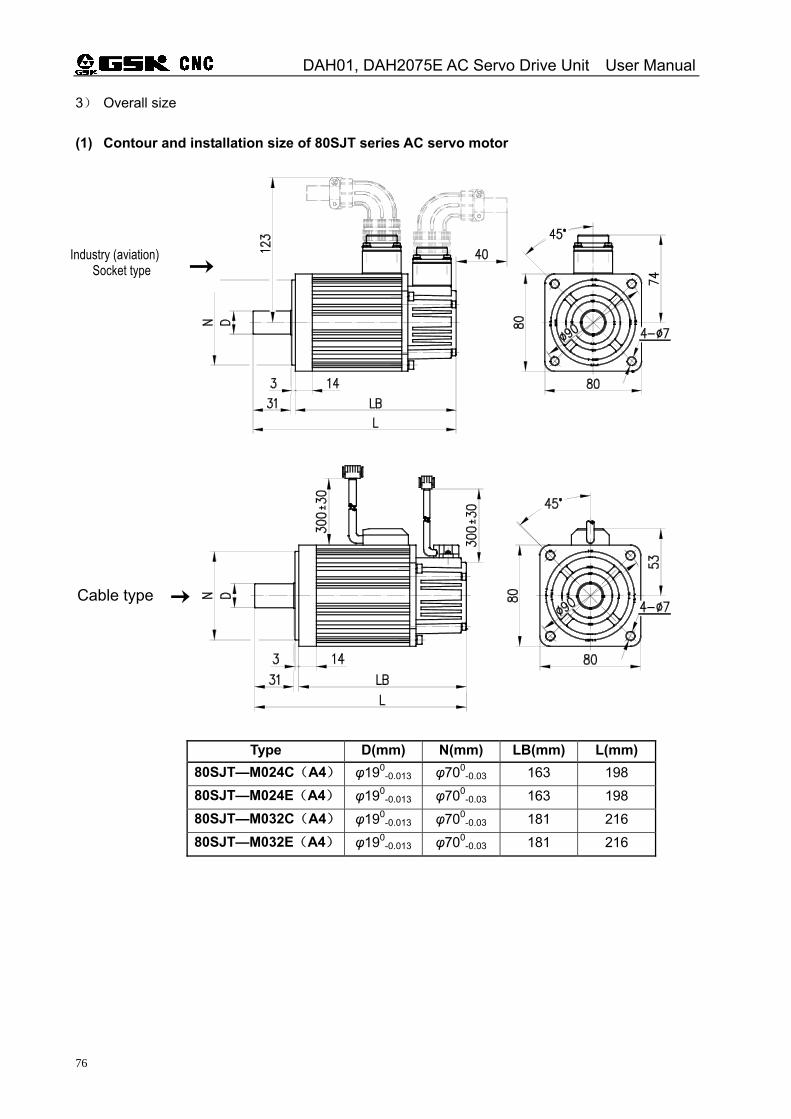
DAH01, DAH2075E AC Servo Drive Unit User Manual
76
3) Overall size (1) Contour and installation size of 80SJT series AC servo motor
Type D(mm) N(mm) LB(mm) L(mm) 80SJT—M024C(A4) φ190
-0.013 φ700-0.03 163 198
80SJT—M024E(A4) φ190-0.013 φ700
-0.03 163 198 80SJT—M032C(A4) φ190
-0.013 φ700-0.03 181 216
80SJT—M032E(A4) φ190-0.013 φ700
-0.03 181 216
Cable type
Industry (aviation) Socket type
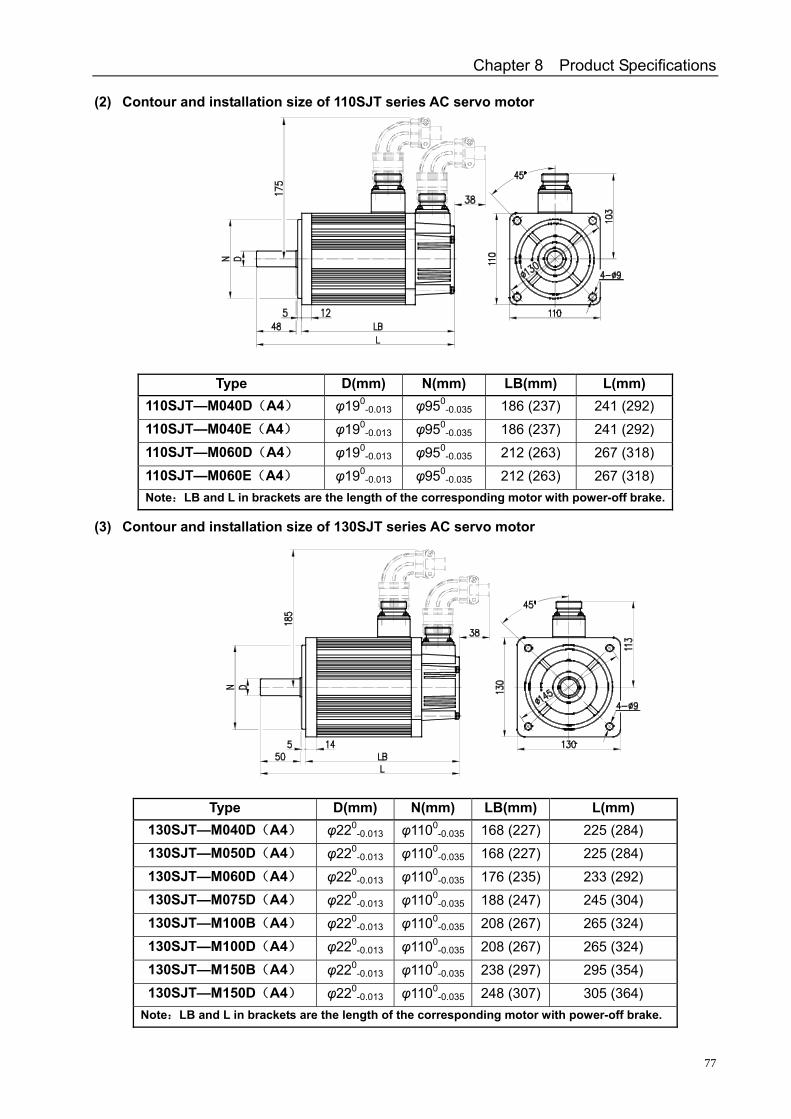
Chapter 8 Product Specifications
77
(2) Contour and installation size of 110SJT series AC servo motor
Type D(mm) N(mm) LB(mm) L(mm) 110SJT—M040D(A4) φ190
-0.013 φ950-0.035 186 (237) 241 (292)
110SJT—M040E(A4) φ190-0.013 φ950
-0.035 186 (237) 241 (292) 110SJT—M060D(A4) φ190
-0.013 φ950-0.035 212 (263) 267 (318)
110SJT—M060E(A4) φ190-0.013 φ950
-0.035 212 (263) 267 (318) Note:LB and L in brackets are the length of the corresponding motor with power-off brake.
(3) Contour and installation size of 130SJT series AC servo motor
Type D(mm) N(mm) LB(mm) L(mm) 130SJT—M040D(A4) φ220
-0.013 φ1100
-0.035 168 (227) 225 (284) 130SJT—M050D(A4) φ220
-0.013 φ1100-0.035 168 (227) 225 (284)
130SJT—M060D(A4) φ220-0.013 φ1100
-0.035 176 (235) 233 (292) 130SJT—M075D(A4) φ220
-0.013 φ1100-0.035 188 (247) 245 (304)
130SJT—M100B(A4) φ220-0.013 φ1100
-0.035 208 (267) 265 (324) 130SJT—M100D(A4) φ220
-0.013 φ1100-0.035 208 (267) 265 (324)
130SJT—M150B(A4) φ220-0.013 φ1100
-0.035 238 (297) 295 (354) 130SJT—M150D(A4) φ220
-0.013 φ1100-0.035 248 (307) 305 (364)
Note:LB and L in brackets are the length of the corresponding motor with power-off brake.
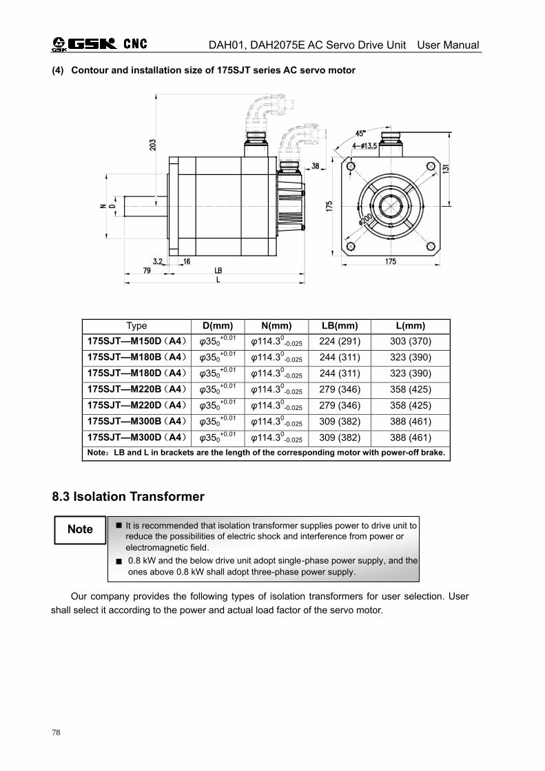
DAH01, DAH2075E AC Servo Drive Unit User Manual
78
(4) Contour and installation size of 175SJT series AC servo motor
Type D(mm) N(mm) LB(mm) L(mm) 175SJT—M150D(A4) φ350
+0.01 φ114.30-0.025 224 (291) 303 (370)
175SJT—M180B(A4) φ350+0.01 φ114.30
-0.025 244 (311) 323 (390) 175SJT—M180D(A4) φ350
+0.01 φ114.30-0.025 244 (311) 323 (390)
175SJT—M220B(A4) φ350+0.01 φ114.30
-0.025 279 (346) 358 (425) 175SJT—M220D(A4) φ350
+0.01 φ114.30-0.025 279 (346) 358 (425)
175SJT—M300B(A4) φ350+0.01 φ114.30
-0.025 309 (382) 388 (461) 175SJT—M300D(A4) φ350
+0.01 φ114.30-0.025 309 (382) 388 (461)
Note:LB and L in brackets are the length of the corresponding motor with power-off brake.
8.3 Isolation Transformer
It is recommended that isolation transformer supplies power to drive unit to reduce the possibilities of electric shock and interference from power or electromagnetic field.
Note
0.8 kW and the below drive unit adopt single-phase power supply, and the ones above 0.8 kW shall adopt three-phase power supply.
Our company provides the following types of isolation transformers for user selection. User
shall select it according to the power and actual load factor of the servo motor.
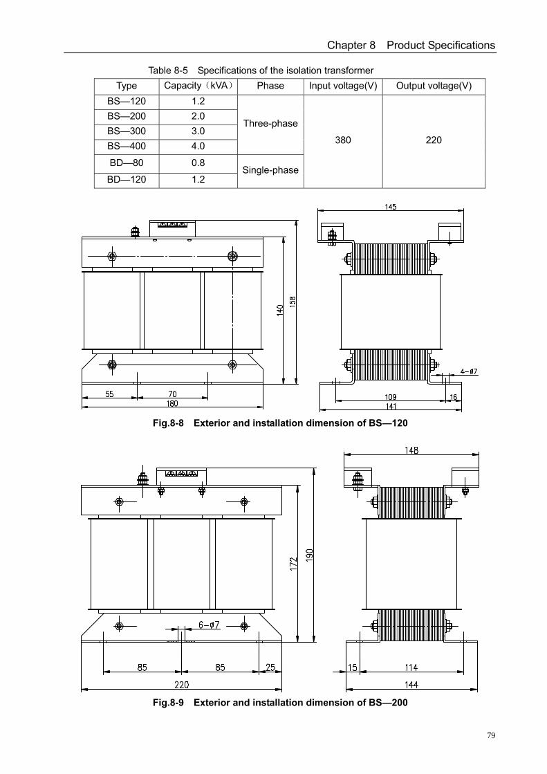
Chapter 8 Product Specifications
79
Table 8-5 Specifications of the isolation transformer Type Capacity(kVA) Phase Input voltage(V) Output voltage(V)
BS—120 1.2 BS—200 2.0 BS—300 3.0 BS—400 4.0
Three-phase
BD—80 0.8
BD—120 1.2 Single-phase
380 220
Fig.8-8 Exterior and installation dimension of BS—120
Fig.8-9 Exterior and installation dimension of BS—200
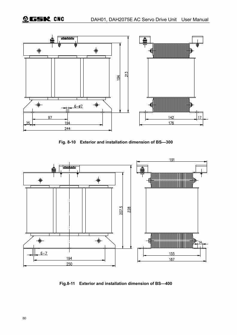
DAH01, DAH2075E AC Servo Drive Unit User Manual
80
Fig. 8-10 Exterior and installation dimension of BS—300
Fig.8-11 Exterior and installation dimension of BS—400
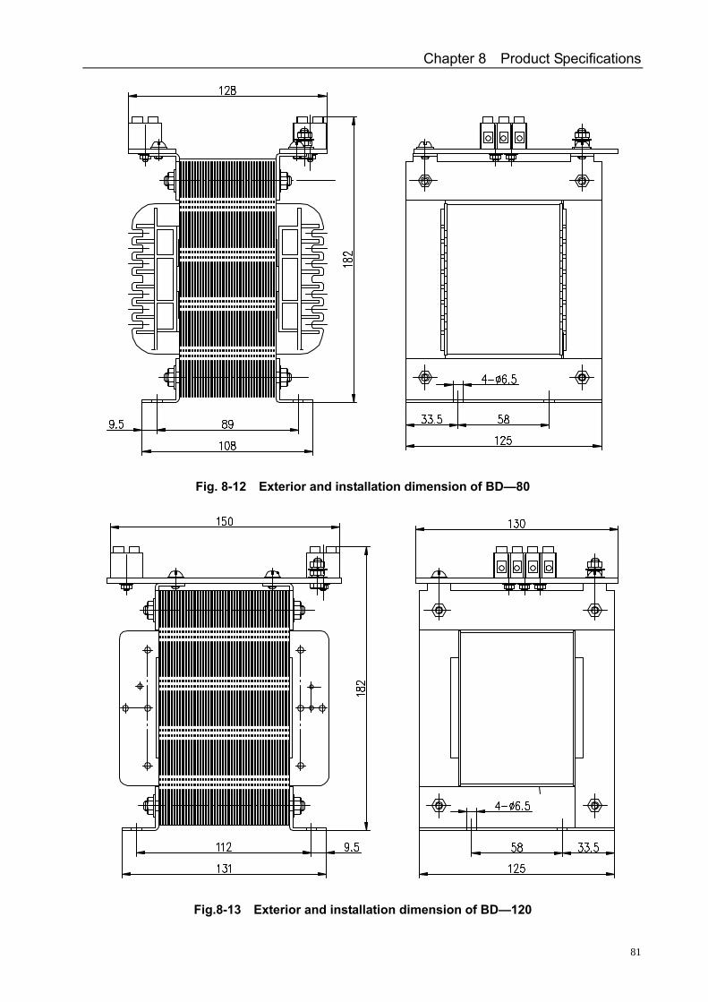
Chapter 8 Product Specifications
81
Fig. 8-12 Exterior and installation dimension of BD—80
Fig.8-13 Exterior and installation dimension of BD—120
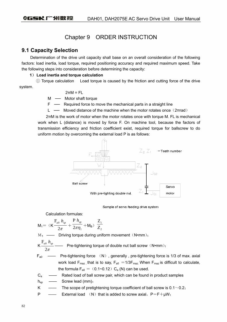
DAH01, DAH2075E AC Servo Drive Unit User Manual
82
Chapter 9 ORDER INSTRUCTION
9.1 Capacity Selection Determination of the drive unit capacity shall base on an overall consideration of the following
factors: load inertia, load torque, required positioning accuracy and required maximum speed. Take the following steps into consideration before determining the capacity:
1) Load inertia and torque calculation T① orque calculation Load torque is caused by the friction and cutting force of the drive system. 2πM = FL
M Motor shaft torque F Required force to move the mechanical parts in a straight line L Moved distance of the machine when the motor rotates once(2πrad)
2πM is the work of motor when the motor rotates once with torque M. FL is mechanical work when L (distance) is moved by force F. On machine tool, because the factors of transmission efficiency and friction coefficient exist, required torque for ballscrew to do uniform motion by overcoming the external load P is as follows:
Calculation formulas:
M1=(K
π2
F 0 spa h+
12Pπη
sph+MB)
2
1ZZ
M1 —— Driving torque during uniform movement(N•mm);
Kπ2
F 0 spa h—— Pre-tightening torque of double nut ball screw(N•mm);
Fa0 —— Pre-tightening force (N), generally , pre-tightening force is 1/3 of max. axial work load Fmaz , that is to say, Fa0 =1/3Fmaz. When Fmaz is difficult to calculate, the formula Fa0 =(0.1~0.12)Ca (N) can be used.
Ca —— Rated load of ball screw pair, which can be found in product samples
hsp —— Screw lead (mm); K —— The scope of pretightening torque coefficient of ball screw is 0.1~0.2;
P —— External load (N)that is added to screw axial,P=F+μW;
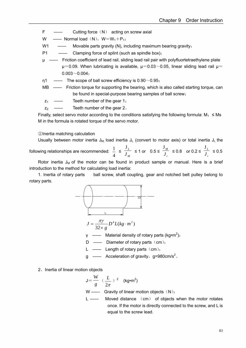
Chapter 9 Order Instruction
83
F —— Cutting force(N) acting on screw axial W —— Normal load(N),W=W1+P1; W1 —— Movable parts gravity (N), including maximum bearing gravity; P1 —— Clamping force of splint (such as spindle box); μ —— Friction coefficient of lead rail, sliding lead rail pair with polyfluortetraethylene plate
μ=0.09. When lubricating is available, μ=0.03~0.05, linear sliding lead rail μ=0.003~0.004;
η1 —— The scope of ball screw efficiency is 0.90~0.95; MB —— Friction torque for supporting the bearing, which is also called starting torque, can
be found in special-purpose bearing samples of ball screw;
z1 —— Teeth number of the gear 1; z2 —— Teeth number of the gear 2。
Finally, select servo motor according to the conditions satisfying the following formula: M1 ≤ Ms M in the formula is rotated torque of the servo motor.
Inertia matching calculation②
Usually between motor inertia JM, load inertia JL (convert to motor axis) or total inertia Jr, the
following relationships are recommended: 41 ≤
M
L
JJ
≤ 1 or 0.5 ≤ r
M
JJ
≤ 0.8 or 0.2 ≤ r
L
JJ
≤ 0.5
Rotor inertia JM of the motor can be found in product sample or manual. Here is a brief introduction to the method for calculating load inertia:
1. Inertia of rotary parts ball screw, shaft coupling, gear and notched belt pulley belong to rotary parts.
)(32
24 mkgLDg
J ⋅×
=πγ
γ —— Material density of rotary parts (kg•m2); D —— Diameter of rotary parts(cm); L —— Length of rotary parts(cm); g —— Acceleration of gravity,g=980cm/s2。 2、Inertia of linear motion objects
J=gW
(π2L
)2 (kg•m2)
W —— Gravity of linear motion objects(N); L —— Moved distance (cm) of objects when the motor rotates
once. If the motor is directly connected to the screw, and L is equal to the screw lead.
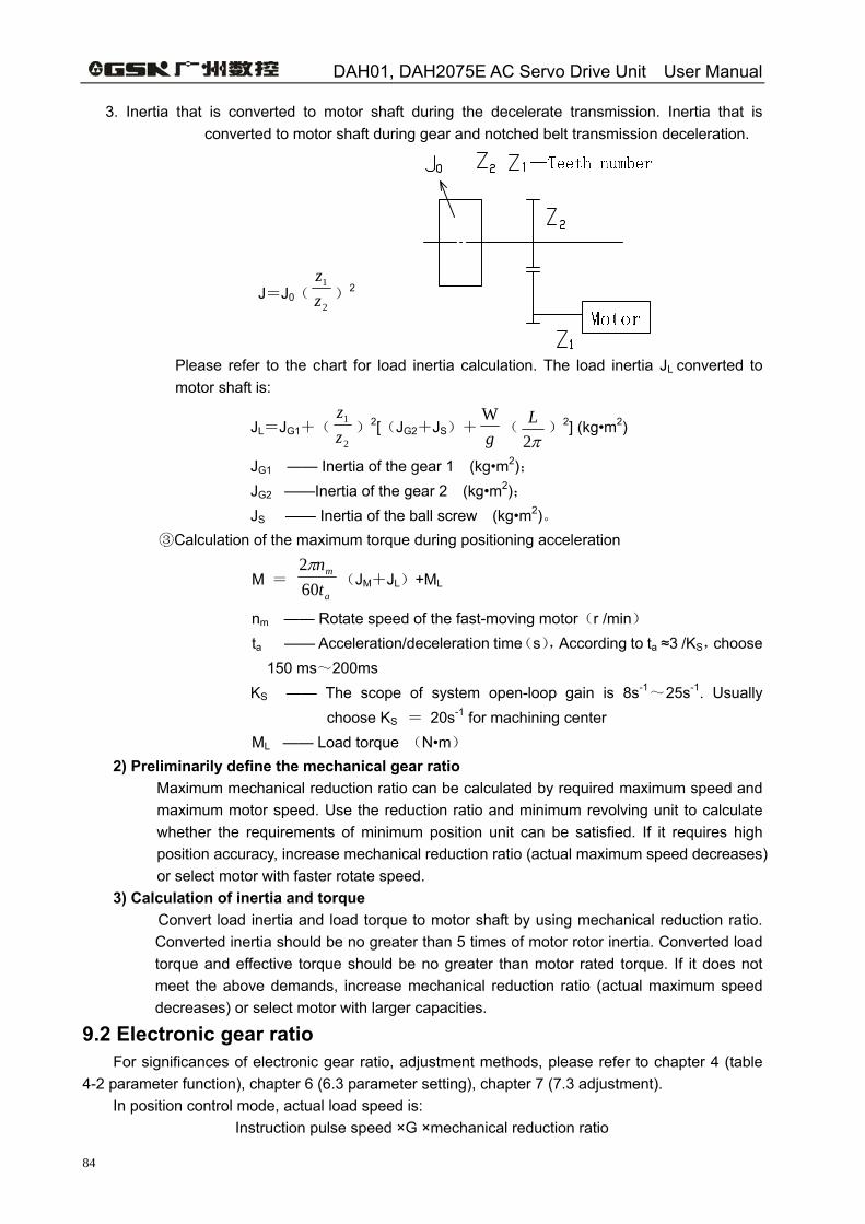
DAH01, DAH2075E AC Servo Drive Unit User Manual
84
3. Inertia that is converted to motor shaft during the decelerate transmission. Inertia that is converted to motor shaft during gear and notched belt transmission deceleration.
J=J0(2
1
zz
)2
Please refer to the chart for load inertia calculation. The load inertia JL converted to motor shaft is:
JL=JG1+(2
1
zz
)2[(JG2+JS)+gW
(π2L
)2] (kg•m2)
JG1 —— Inertia of the gear 1 (kg•m2); JG2 ——Inertia of the gear 2 (kg•m2); JS —— Inertia of the ball screw (kg•m2)。
Calculation of the ③ maximum torque during positioning acceleration
M = a
m
tn
602π
(JM+JL)+ML
nm —— Rotate speed of the fast-moving motor(r /min) ta —— Acceleration/deceleration time(s),According to ta ≈3 /KS,choose
150 ms~200ms KS —— The scope of system open-loop gain is 8s-1~25s-1. Usually
choose KS = 20s-1 for machining center
ML —— Load torque (N•m) 2) Preliminarily define the mechanical gear ratio
Maximum mechanical reduction ratio can be calculated by required maximum speed and maximum motor speed. Use the reduction ratio and minimum revolving unit to calculate whether the requirements of minimum position unit can be satisfied. If it requires high position accuracy, increase mechanical reduction ratio (actual maximum speed decreases) or select motor with faster rotate speed.
3) Calculation of inertia and torque Convert load inertia and load torque to motor shaft by using mechanical reduction ratio. Converted inertia should be no greater than 5 times of motor rotor inertia. Converted load torque and effective torque should be no greater than motor rated torque. If it does not meet the above demands, increase mechanical reduction ratio (actual maximum speed decreases) or select motor with larger capacities.
9.2 Electronic gear ratio For significances of electronic gear ratio, adjustment methods, please refer to chapter 4 (table 4-2 parameter function), chapter 6 (6.3 parameter setting), chapter 7 (7.3 adjustment).
In position control mode, actual load speed is: Instruction pulse speed ×G ×mechanical reduction ratio
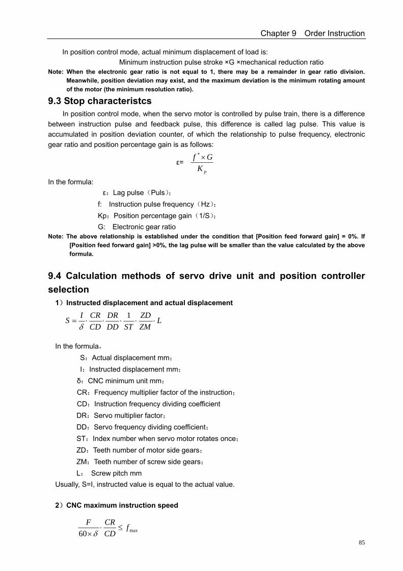
Chapter 9 Order Instruction
85
In position control mode, actual minimum displacement of load is: Minimum instruction pulse stroke ×G ×mechanical reduction ratio
Note: When the electronic gear ratio is not equal to 1, there may be a remainder in gear ratio division. Meanwhile, position deviation may exist, and the maximum deviation is the minimum rotating amount of the motor (the minimum resolution ratio).
9.3 Stop characteristcs In position control mode, when the servo motor is controlled by pulse train, there is a difference
between instruction pulse and feedback pulse, this difference is called lag pulse. This value is accumulated in position deviation counter, of which the relationship to pulse frequency, electronic gear ratio and position percentage gain is as follows:
ε=pKGf ×*
In the formula: ε:Lag pulse(Puls);
f: Instruction pulse frequency(Hz); Kp:Position percentage gain(1/S); G: Electronic gear ratio
Note: The above relationship is established under the condition that [Position feed forward gain] = 0%. If [Position feed forward gain] >0%, the lag pulse will be smaller than the value calculated by the above formula.
9.4 Calculation methods of servo drive unit and position controller selection
1)Instructed displacement and actual displacement
In the formula,
S:Actual displacement mm; I:Instructed displacement mm; δ:CNC minimum unit mm; CR:Frequency multiplier factor of the instruction; CD:Instruction frequency dividing coefficient
DR:Servo multiplier factor; DD:Servo frequency dividing coefficient; ST:Index number when servo motor rotates once; ZD:Teeth number of motor side gears; ZM:Teeth number of screw side gears; L: Screw pitch mm
Usually, S=I, instructed value is equal to the actual value. 2)CNC maximum instruction speed
max60f
CDCRF
≤⋅×δ
LZMZD
STDDDR
CDCRIS ⋅⋅⋅⋅⋅=
1δ
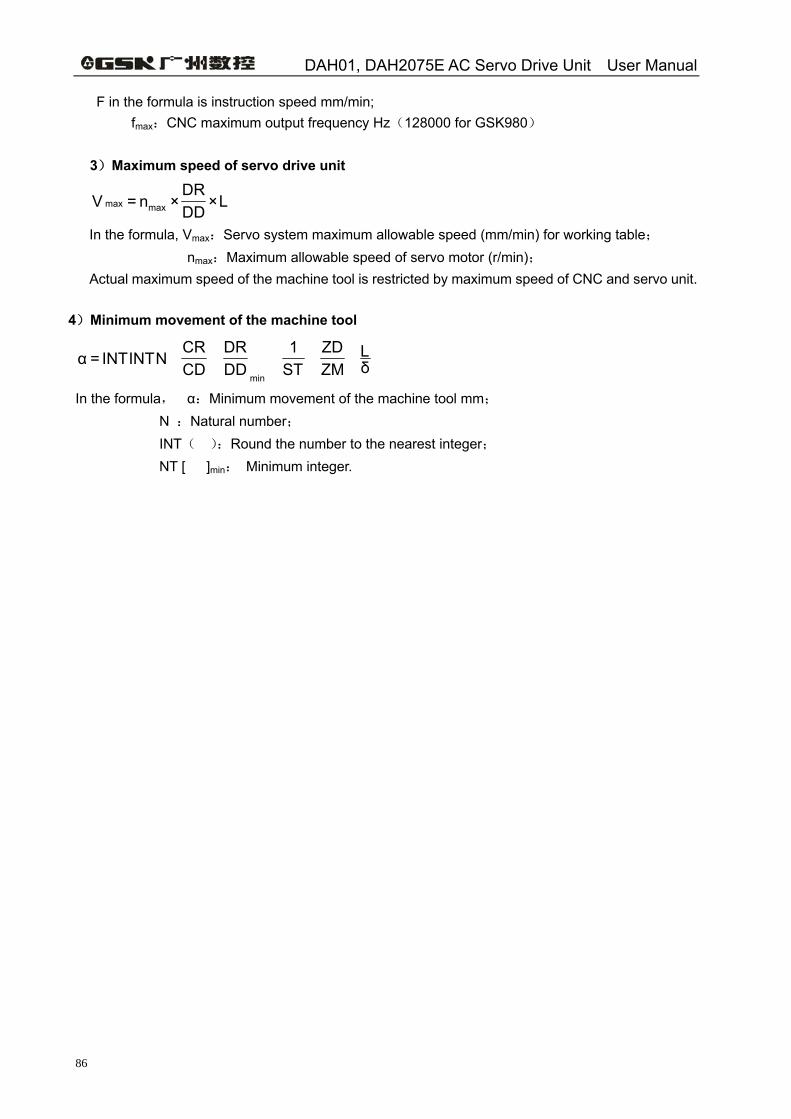
DAH01, DAH2075E AC Servo Drive Unit User Manual
86
F in the formula is instruction speed mm/min; fmax:CNC maximum output frequency Hz(128000 for GSK980)
3)Maximum speed of servo drive unit
L×DDDR
×n=V maxmax
In the formula, Vmax:Servo system maximum allowable speed (mm/min) for working table; nmax:Maximum allowable speed of servo motor (r/min);
Actual maximum speed of the machine tool is restricted by maximum speed of CNC and servo unit.
4)Minimum movement of the machine tool
δL
ZMZD
ST1
DDDR
CDCR
NINTINT=αmin
In the formula, α:Minimum movement of the machine tool mm; N :Natural number; INT( ):Round the number to the nearest integer; NT [ ]min: Minimum integer.