Embed Size (px)
Citation preview

Page 1
User manual for Ekoheat pellet boiler
Dear Customer
Congratulations on your new Ekoheat pellet boiler from Ekopower.
Please read this manual thoroughly before starting the
installation.
Page 2 : Mounting of the Ekoheat pellet boiler
Page 3 : Initial start-up
Page 4-9 : The controller
Page 10-11 : Cleaning and maintenance
Page 12 : Electrical chart of the control
Page 13 : Accessories
Page 14-15 : Fault finding
Page 16 : Software up-dating
Page 17 : Technical specifications
Page 18 : Warranty
Page 19 : CE-Marking
Page 20-23 : Test of approval
Page 24 : Marks of approval
The pellet boiler from Ekopower has been
tested by Dansk Teknologisk Institut
according to the following norm:
Ekoheat 900 = EN 303-5:1999
Ekoheat 1500 = EN 303-5:1999
Ekoheat 2500 = EN 303-5:1999
Ekoheat 4000 = EN 303-5:2012
All systems are marked AA
A = Efficiency / A = Environment Ekoheat pellet boilers are CE marked.
Best regards
Dan Elkjær
Managing
director
Warning
Ekoheat pellet boiler must not be
operated by minors.
Top plate as well as front gate,
must always be mounted during
operation.

Page 2
Mounting of the Ekoheat pellet boiler
Mounting of the Ekoheat pellet boiler must be done in accordance to firetechnical guidelines, and must be mounted
by an of Ekopower authorised technical assistant.
It is also recommended by Ekopower to contact the chimney sweeper before mounting is started, and that the pellet
boiler is carefully checked for damages occured during transportation.
Do only mount the Ekoheat pellet boiler in an appropriate dry and insulated room with good ventilation. Please
ensure that the boiler gets plenty of fresh air due to which it is demanded there is an opening in the boiler room to
the outside of at least 20 cm2.
The floor must not be of combustible material and must be plane, as it is required the boiler is levelled. (The legs must not be adjusted, as these keep the casing)
When putting the boiler in place be careful as the covering of the boiler is ”loose” and is only resting on the bottom
plate. It is recommended to demount the burner and the ashpan to minimize the weight. Remember the front gate
must be mounted when pushing the boiler in space.
Once the boiler is levelled, connect it to the chimney with the flue gas pipe. Note that the flue gas outlet of the
boiler is universal and can be mounted directly on top of or on the back of the boiler. If you choose the back side fit
the prepared plate and move the cover plate on the back to the top of the boiler. You then do not have to fit the top
plate.
The flue pipe should not be more than 0,5 m long and must always be rising. If the flue pipe extend more than 0,5
meter, or if bendings are mounted, then it must always be insulated.
The draught in the chimney must be stable and not below 0,15 mb (15 Pa). If the draught varies more than +/- 0,05 mBar, a draught stabilizer must be mounted. Mounting of a draught stabilizer in the chimney must minimum be 0,5 meter above the flue gas inlet of the boiler.
The enclosed retards must not be mounted at initial start-up. They can be mounted if the flue gas temperature
extend more than 150o constantly after 14 days. Please note that if retards are mounted all retards must be
mounted. Eventually contact Ekopower for more information.
The Ekoheat pellet boiler must be mounted with shunt valve so that the return water is maximum 15o lower than the
flow temperature. The flow temperature must minimum be 60oC.
Please note that if the flue pipe and the shunt valve not are correctly mounted the warranty will be null and void.
Now place the hopper on the side of the boiler you prefer, and place the cover plate for the auger hole on the
opposite side. Do the same for as well the boiler as the hopper.
The whole control board must be demounted by 4 screws and place it carefully on the top of the boiler. Now the
auger is carefully “reversed” pushed through the hole from the boiler and into the hopper. The auger is in place when
the outlet is over the fall pipe of the boiler. Then mount the control board again and insert the plug from the auger in
the control board. Note that there are 2 similar plugs where it says “Ekocompress” on one and “External feeder” on
the other. The auger is mounted in “External feeder”.

Page 3
Initial start-up
Check if there is water on the system and if the system has been ventilated. The
power supply for the boiler MUST be connected to earth.
Now connect the power and the display will immediately lighten up with the
Ekopower logo and after app. 5 sec. a grapich picture will emerge on the screen.
Press ”INFO” for a start and check that it is the same type of Ekoheat which is
mentioned in the control as just have been installed. (Look for more info under
Fault Finding, if it is the wrong size).
Now adjust the watch and the date. This is done by pressing Menu/user
settings/watch and date. Press on the number which you would like to insert and
press OK when the number has been inserted.
Check the time of moving of the ashplate. Press Menu/user settings/clean now.
Choose 1 and wait for 80 seconds. (The burner must be mounted in the boiler while
this is done). When the time has elapsed, take out the burner and the bottom plate
must then be at the same line as the back plate of the burner. If this is not the case,
then correct the time in Menu/serviceman/movement back plate up or down by 1
second at a time.
Calibration of the auger must be done before start-up of the boiler, as it then will
not obtain the ultimate combustion and thus have a lower efficiency. Press
Menu/user settings/adjust/calibration auger. Now start with demounting of the
flexible tube on the outlet. Then mount a bag on the outlet of the external auger
and then press ”Start” under ”Manual operation”. Let the auger run for minimum
15 minutes and then put the wood pellets in the hopper again.
Then mount the bag on the outlet of the auger again and press ”Start” under
”Dosing test”. The control now starts to count down from 200 and has finished
when it reaches 0. Then weigh the bag, and the weight of the pellets is inserted
under “Amount by 200 dosings” which by standard is 1450 g.
This calibration must be repeated again after passing through 200 kg of wood
pellets or at the latest when the boiler has been running for 14 days. This must
also be done again if the magazine has been emptied, when you change the size of
wood pellets or the mark of wood pellets.
Now press “Finish” and mount the flexible tube on the outlet of the auger. Mount
the front gate of the boiler again. The boiler is now ready for the initial start-up,
then press “Start”.
If the boiler does not start after this, then look for more info under Fault Finding.
På linie med
bagplade
Page 4
The controller
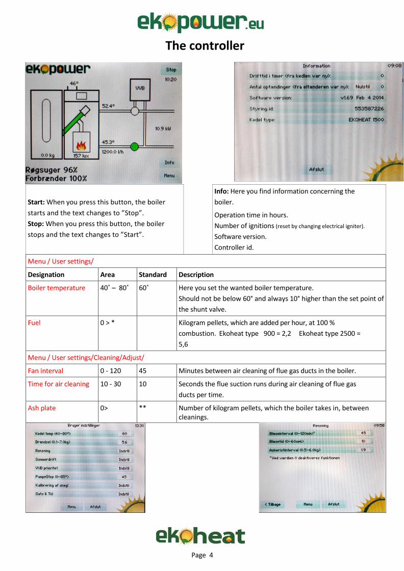
Start: When you press this button, the boiler
starts and the text changes to ”Stop”.
Stop: When you press this button, the boiler
stops and the text changes to ”Start”.
Info: Here you find information concerning the
boiler.
Operation time in hours.
Number of ignitions (reset by changing electrical igniter).
Software version.
Controller id.
Boiler type. Menu / User settings/
Designation Area Standard Description
Boiler temperature 40˚ – 80˚ 60˚ Here you set the wanted boiler temperature.
Should not be below 60° and always 10° higher than the set point of
the shunt valve.
Fuel 0 > * Kilogram pellets, which are added per hour, at 100 %
combustion. Ekoheat type 900 = 2,2 Ekoheat type 2500 =
5,6
Ekoheat type 1500 = 3,1 Ekoheat type 4000 = 8,8. Menu / User settings/Cleaning/Adjust/
Fan interval 0 - 120 45 Minutes between air cleaning of flue gas ducts in the boiler.
Time for air cleaning 10 - 30 10 Seconds the flue suction runs during air cleaning of flue gas
ducts per time.
Ash plate 0> ** Number of kilogram pellets, which the boiler takes in, between cleanings.

Page 5
Menu / User settings/Summer operation
Designation Area Standard Description
Summer operation 1 > Summer operation can optional be set for 1 to 5 periods.
Each period must minimum be 1 hour. Hours are typed
under TT and minutes under MM. If not all periods are
being used, nothing are typed in these. Once the periods
have been typed, press “No” and this changes to “Yes”.
After this press “Save and restart”.
Menu / User settings /VVB Priority
If there is a temperature sensor installed in the hot water
tank and connected to the controller, you can reset the
summer operation in all periods and only run the boiler
when hot water is needed. The temperature of this must
be set under VVB priority. Summer operation must be
activated to do this and this can be checked by the
appearance of a sun in the graphics on the front page.
Designation Area Standard Description
VVB Priority Make the boiler produce hot water (domestic water). To
use the function use an Ekopower priority sensor and a
230 V motor powered valve. In the menu you set the
wanted hot water temperature, and how much the
temperature is allowed to drop before the domestic
water need heating again.
VVB Priority Yes/No No Change to Yes, if this is connected to the installation.
VVB Temp. 0 - 70˚ 60˚ The temperature in the hot water tank.
VVB Drop 0 - 20˚ 10˚ Temperature drop in the hot water tank before the boiler makes priorities. We recommend that the temperature
drop does not get below 10o.

Page 6
Menu / User settings /
Area Standard Description
Pump stop 5 – 85˚ 45 If the circulation pump is connected to the boiler, this will run when the temperature of the boiler is above set point,
and stops when this is below again. Ekopower recommends
to set pump stop at 55˚ and the boiler temperature at 65˚by
engagement of summer operation.
Pump stop must not be set at null.
Calibration of auger See page 3.
Date and time Adjustment of date and time.
Page 7
Ved alarm se under fejlfinding.
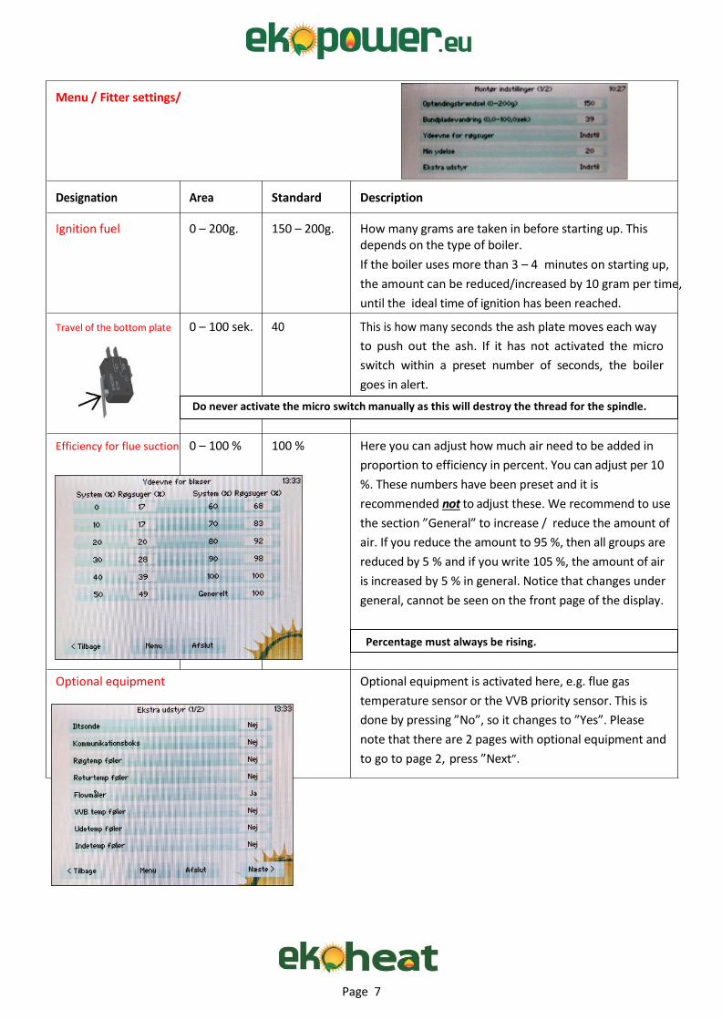
Menu / Fitter settings/
Designation Area Standard Description
Ignition fuel 0 – 200g. 150 – 200g. How many grams are taken in before starting up. This depends on the type of boiler.
If the boiler uses more than 3 – 4 minutes on starting up,
the amount can be reduced/increased by 10 gram per time,
until the ideal time of ignition has been reached.
Travel of the bottom plate 0 – 100 sek. 40 This is how many seconds the ash plate moves each way
to push out the ash. If it has not activated the micro
switch within a preset number of seconds, the boiler
goes in alert.
Do never activate the micro switch manually as this will destroy the thread for the spindle.
Efficiency for flue suction 0 – 100 % 100 % Here you can adjust how much air need to be added in
proportion to efficiency in percent. You can adjust per 10
%. These numbers have been preset and it is
recommended not to adjust these. We recommend to use
the section ”General” to increase / reduce the amount of
air. If you reduce the amount to 95 %, then all groups are
reduced by 5 % and if you write 105 %, the amount of air
is increased by 5 % in general. Notice that changes under
general, cannot be seen on the front page of the display.
Percentage must always be rising.
Optional equipment Optional equipment is activated here, e.g. flue gas
temperature sensor or the VVB priority sensor. This is
done by pressing ”No”, so it changes to ”Yes”. Please
note that there are 2 pages with optional equipment and
to go to page 2, press ”Next”.
Page 8
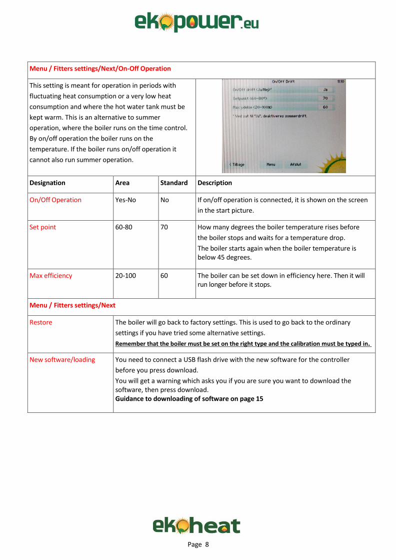
Menu / Fitters settings/Next/On-Off Operation
This setting is meant for operation in periods with
fluctuating heat consumption or a very low heat
consumption and where the hot water tank must be
kept warm. This is an alternative to summer
operation, where the boiler runs on the time control.
By on/off operation the boiler runs on the
temperature. If the boiler runs on/off operation it
cannot also run summer operation.
Designation Area Standard Description
On/Off Operation Yes-No No If on/off operation is connected, it is shown on the screen
in the start picture.
Set point 60-80 70 How many degrees the boiler temperature rises before
the boiler stops and waits for a temperature drop.
The boiler starts again when the boiler temperature is below 45 degrees.
Max efficiency 20-100 60 The boiler can be set down in efficiency here. Then it will run longer before it stops.
Menu / Fitters settings/Next
Restore The boiler will go back to factory settings. This is used to go back to the ordinary
settings if you have tried some alternative settings.
Remember that the boiler must be set on the right type and the calibration must be typed in.
New software/loading You need to connect a USB flash drive with the new software for the controller
before you press download.
You will get a warning which asks you if you are sure you want to download the software, then press download. Guidance to downloading of software on page 15
Page 9
Menu /
Designation Description
Correct content of hopper
You can change the number, when you have been
adding pellets. The number will get smaller as the
pellets are being used. It is a theoretical calculated
number which only tells how many kilos there are in
the hopper. The boiler is not controlled by this
number.
Clean now Here you can make a manual movement of the ash
plate, which means that you push the ash out in the
ashpan. You can choose if it supposed to do so 1 or 5
times.
Language Here you will see different flags as a symbol of which
language you want on the boiler.
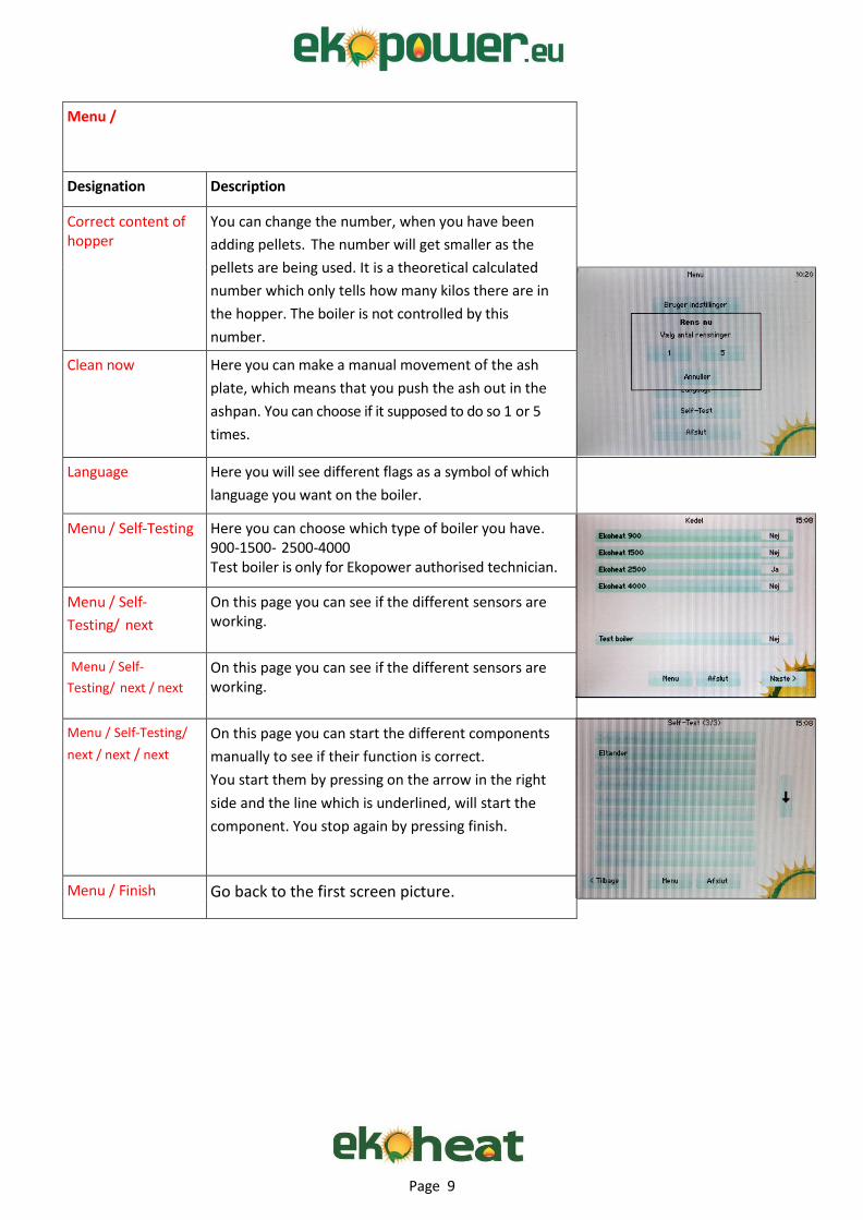
Menu / Self-Testing Here you can choose which type of boiler you have. 900-1500- 2500-4000 Test boiler is only for Ekopower authorised technician.
Menu / Self-
Testing/ next
On this page you can see if the different sensors are working.
Menu / Self-
Testing/ next / next
On this page you can see if the different sensors are working.
Menu / Self-Testing/
next / next / next
On this page you can start the different components
manually to see if their function is correct.
You start them by pressing on the arrow in the right
side and the line which is underlined, will start the
component. You stop again by pressing finish.
Menu / Finish Go back to the first screen picture.
Page 10
Maintenance and cleaning Type Description
Before cleaning Turn off the burner on the control ( stop ) Wait for 15 min. so the
burner gets cold before anything is demounted. Take care that
wires are not broken or pulled during cleaning.
The hopper Refill the hopper before it is totally empty. If the auger is not
covered with pellets irregularities will occur in the operation, as the
burner do not get the right amount of pellets. Wood pellets contain
sawdust, and it might pile up by the auger depending on how much
dust there is in the pellets. (quality of the pellets). Because of this it is
recommended to empty the hopper from time to time. By much dust
there is a risk that the amount the auger feeds will change and this
might cause operation stop.
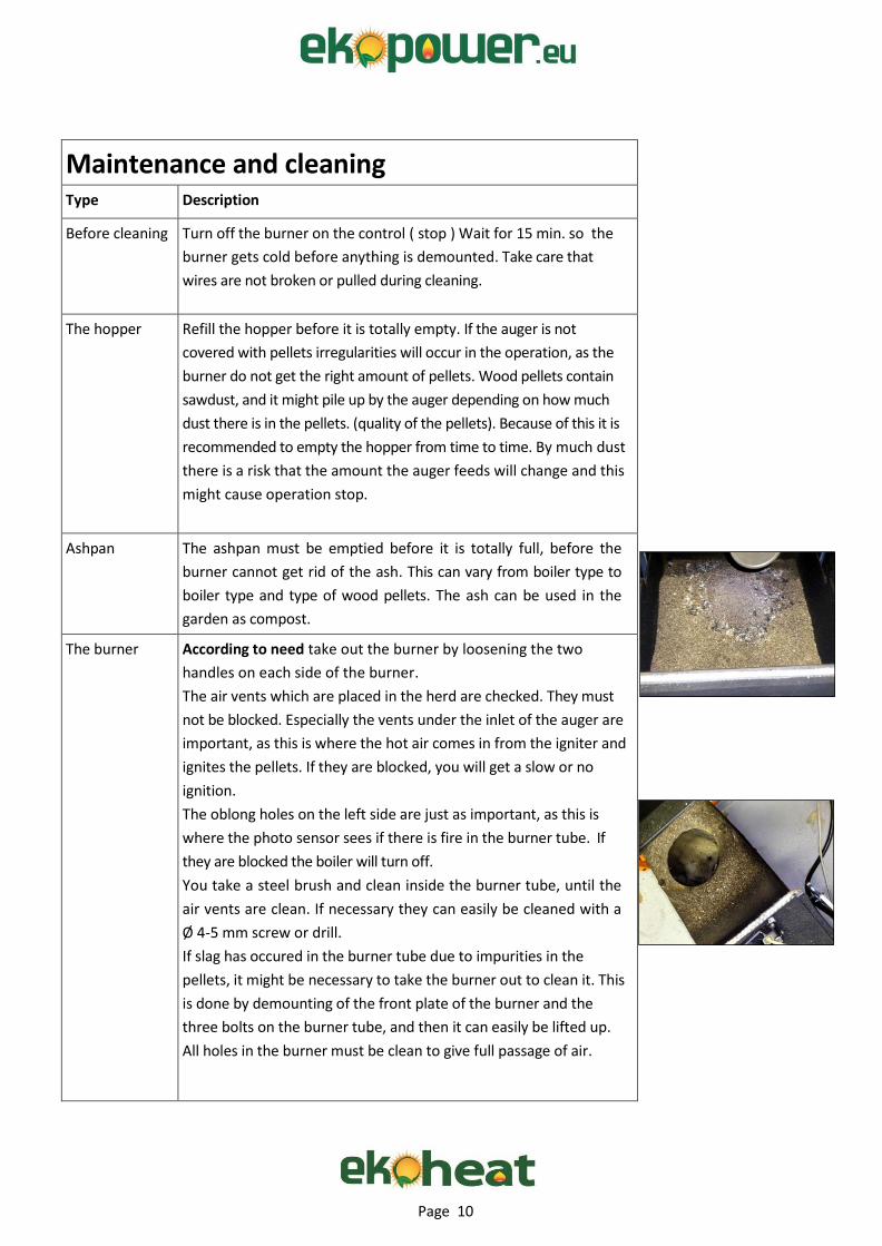
Ashpan The ashpan must be emptied before it is totally full, before the
burner cannot get rid of the ash. This can vary from boiler type to
boiler type and type of wood pellets. The ash can be used in the
garden as compost.
The burner According to need take out the burner by loosening the two
handles on each side of the burner.
The air vents which are placed in the herd are checked. They must
not be blocked. Especially the vents under the inlet of the auger are
important, as this is where the hot air comes in from the igniter and
ignites the pellets. If they are blocked, you will get a slow or no
ignition.
The oblong holes on the left side are just as important, as this is
where the photo sensor sees if there is fire in the burner tube. If
they are blocked the boiler will turn off.
You take a steel brush and clean inside the burner tube, until the
air vents are clean. If necessary they can easily be cleaned with a
Ø 4-5 mm screw or drill.
If slag has occured in the burner tube due to impurities in the
pellets, it might be necessary to take the burner out to clean it. This
is done by demounting of the front plate of the burner and the
three bolts on the burner tube, and then it can easily be lifted up.
All holes in the burner must be clean to give full passage of air.
Page 11
Type Description
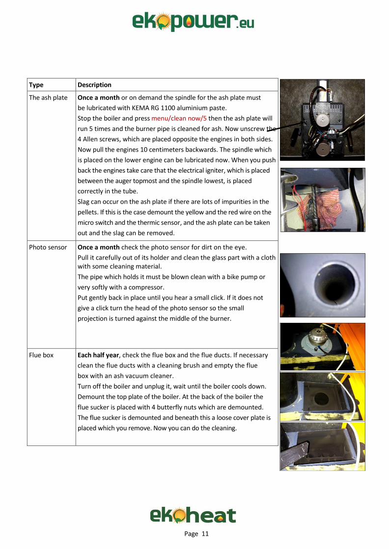
The ash plate Once a month or on demand the spindle for the ash plate must
be lubricated with KEMA RG 1100 aluminium paste.
Stop the boiler and press menu/clean now/5 then the ash plate will
run 5 times and the burner pipe is cleaned for ash. Now unscrew the
4 Allen screws, which are placed opposite the engines in both sides.
Now pull the engines 10 centimeters backwards. The spindle which
is placed on the lower engine can be lubricated now. When you push
back the engines take care that the electrical igniter, which is placed
between the auger topmost and the spindle lowest, is placed
correctly in the tube.
Slag can occur on the ash plate if there are lots of impurities in the
pellets. If this is the case demount the yellow and the red wire on the
micro switch and the thermic sensor, and the ash plate can be taken
out and the slag can be removed.
Photo sensor Once a month check the photo sensor for dirt on the eye.
Pull it carefully out of its holder and clean the glass part with a cloth with some cleaning material.
The pipe which holds it must be blown clean with a bike pump or
very softly with a compressor.
Put gently back in place until you hear a small click. If it does not
give a click turn the head of the photo sensor so the small
projection is turned against the middle of the burner.
Flue box Each half year, check the flue box and the flue ducts. If necessary
clean the flue ducts with a cleaning brush and empty the flue
box with an ash vacuum cleaner.
Turn off the boiler and unplug it, wait until the boiler cools down.
Demount the top plate of the boiler. At the back of the boiler the
flue sucker is placed with 4 butterfly nuts which are demounted.
The flue sucker is demounted and beneath this a loose cover plate is
placed which you remove. Now you can do the cleaning.

Page 12
Electrical chart of the control
Page 13
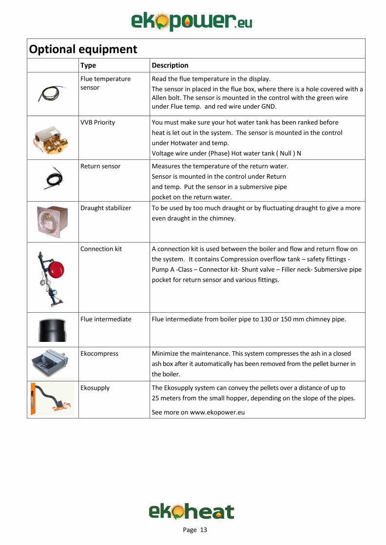
Optional equipment Type Description
Flue temperature sensor
Read the flue temperature in the display.
The sensor in placed in the flue box, where there is a hole covered with a Allen bolt. The sensor is mounted in the control with the green wire under Flue temp. and red wire under GND.
VVB Priority You must make sure your hot water tank has been ranked before
heat is let out in the system. The sensor is mounted in the control
under Hotwater and temp.
Voltage wire under (Phase) Hot water tank ( Null ) N
Return sensor Measures the temperature of the return water.
Sensor is mounted in the control under Return
and temp. Put the sensor in a submersive pipe
pocket on the return water.
Draught stabilizer To be used by too much draught or by fluctuating draught to give a more
even draught in the chimney.
Connection kit A connection kit is used between the boiler and flow and return flow on
the system. It contains Compression overflow tank – safety fittings -
Pump A -Class – Connector kit- Shunt valve – Filler neck- Submersive pipe
pocket for return sensor and various fittings.
Flue intermediate Flue intermediate from boiler pipe to 130 or 150 mm chimney pipe.
Ekocompress Minimize the maintenance. This system compresses the ash in a closed
ash box after it automatically has been removed from the pellet burner in
the boiler.
Ekosupply The Ekosupply system can convey the pellets over a distance of up to
25 meters from the small hopper, depending on the slope of the pipes.
See more on www.ekopower.eu
Page 14
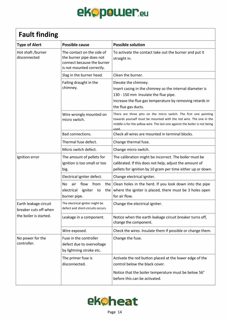
Fault finding Type of Alert Possible cause Possible solution
Hot shaft /burner disconnected
The contact on the side of the burner pipe does not connect because the burner is not mounted correctly.
To activate the contact take out the burner and put it
straight in.
Slag in the burner head. Clean the burner.
Failing draught in the chimney.
Elevate the chimney.
Insert casing in the chimney so the internal diameter is
130 - 150 mm Insulate the flue pipe.
Increase the flue gas temperature by removing retards in
the flue gas ducts.
Wire wrongly mounted on micro switch.
There are three pins on the micro switch. The first one pointing
towards yourself must be mounted with the red wire. The one in the
middle is for the yellow wire. The last one against the boiler is not being
used.
Bad connections. Check all wires are mounted in terminal blocks.
Thermal fuse defect. Change thermal fuse.
Micro switch defect. Change micro switch.
Ignition error The amount of pellets for
ignition is too small or too
big.
The calibration might be incorrect. The boiler must be
calibrated. If this does not help, adjust the amount of
pellets for ignition by 10 gram per time either up or down.
Electrical igniter defect. Change electrical igniter.
No air flow from the
electrical igniter to the
burner pipe.
Clean holes in the herd. If you look down into the pipe
where the igniter is placed, there must be 3 holes open
for air flow.
Earth leakage circuit
breaker cuts off when
the boiler is started.
The electrical igniter might be
defect and short-circuits occurs. Change the electrical igniter.
Leakage in a component. Notice when the earth leakage circuit breaker turns off, change the component.
Wire exposed. Check the wires. Insulate them if possible or change them.
No power for the controller.
Fuse in the controller
defect due to overvoltage
by lightning stroke etc.
Change the fuse.
The primer fuse is
disconnected.
Activate the red button placed at the lower edge of the
control below the black cover.
Notice that the boiler temperature must be below 56°
before this can be activated.
Page 15
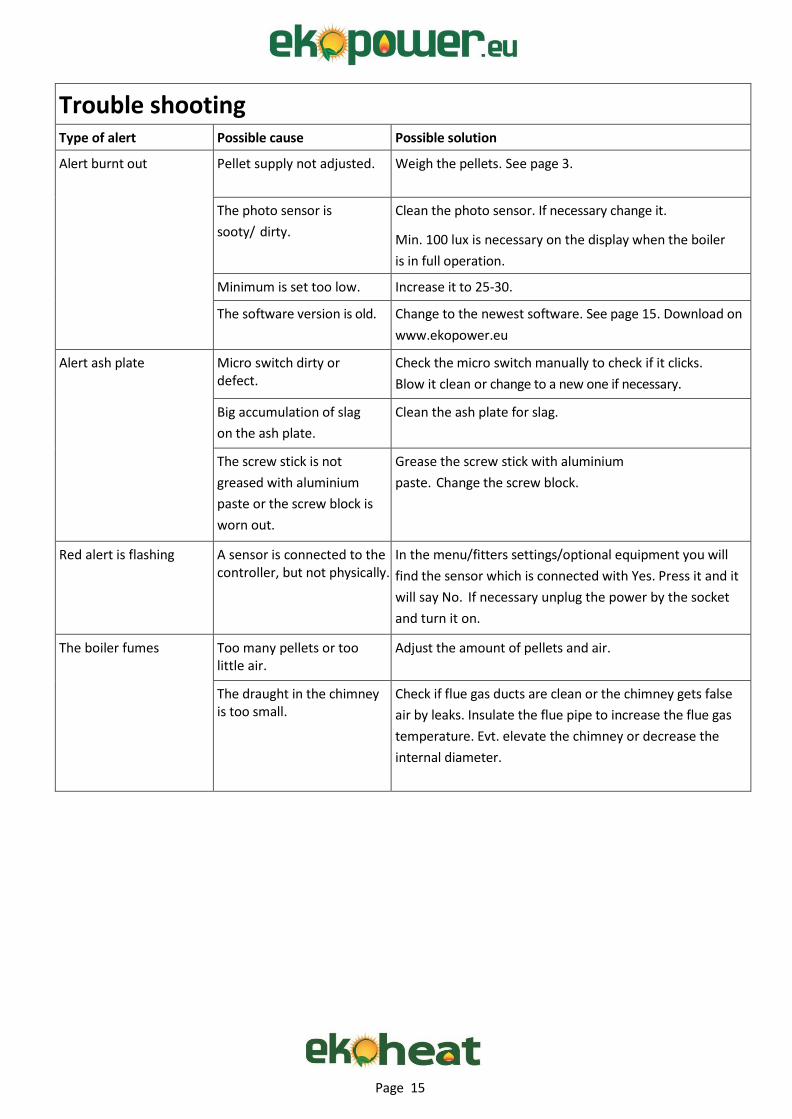
Trouble shooting Type of alert Possible cause Possible solution
Alert burnt out Pellet supply not adjusted. Weigh the pellets. See page 3.
The photo sensor is
sooty/ dirty.
Clean the photo sensor. If necessary change it.
Min. 100 lux is necessary on the display when the boiler
is in full operation.
Minimum is set too low. Increase it to 25-30.
The software version is old. Change to the newest software. See page 15. Download on
www.ekopower.eu
Alert ash plate Micro switch dirty or defect.
Check the micro switch manually to check if it clicks.
Blow it clean or change to a new one if necessary.
Big accumulation of slag
on the ash plate.
Clean the ash plate for slag.
The screw stick is not
greased with aluminium
paste or the screw block is
worn out.
Grease the screw stick with aluminium
paste. Change the screw block.
Red alert is flashing A sensor is connected to the controller, but not physically.
In the menu/fitters settings/optional equipment you will
find the sensor which is connected with Yes. Press it and it
will say No. If necessary unplug the power by the socket
and turn it on.
The boiler fumes Too many pellets or too little air.
Adjust the amount of pellets and air.
The draught in the chimney is too small.
Check if flue gas ducts are clean or the chimney gets false
air by leaks. Insulate the flue pipe to increase the flue gas
temperature. Evt. elevate the chimney or decrease the
internal diameter.

Page 16
USB Flash drive
Software update
1. Buy a new USB flash drive. (Alternatively a used one can be used as long all data are deleted before use).
2. Open the enclosed ZIP file. (Do NOT COPY the ZIP file).
3. First copy the file ”DTX9003.uc3 ”to the USB flash drive and then copy the file ”license.key”.
Installation
1. Demount the controller by unscrewing 6 screws. 2 pcs. vertical upwards, 2. pcs. vertical downwards and the last 2 pcs. under the control panel in each side. (On newer boilers the rubber plug on the back side of the controller box is demounted and the USB flash drive can be inserted in the USB port.)
2. Then carefully lift out the controller.
3. The USB flash drive is inserted in the USB port app. on the middle of the printed circuit board.
4. Now press ”MENU” in the display.
5. Then press ”FITTERS SETTINGS” and next.
6. Then press ”DOWNLOAD” by ”NEW SOFTWARE”
7. The screen will now turn black for 15 – 20 seconds.
8. Then the EKOPOWER logo will turn up and it will count down from 5.
9. Demount the USB flash drive.
10. Mount the controller again.
NOTICE: The controller might have restored ALL settings and ALL settings might be set for EKOHEAT 900. (Remember to insert the right amount of pellets in ”CALIBRATION”)
If you have another size of boiler, then change it the following way:
1. Press ”MENU” on the display.
2. Press ”SELF TEST”.
3. Press ”NO” at the right size of boiler. This will then change to ”YES”
Now press ”START ” in the di spl ay.

Page 17
Technical specifications etc. Producer: Ekopower ApS, Rømøvænget 163 , DK-5500 Middelfart, DK
Model Ekoheat 900 Ekoheat 1500 Ekoheat 2500 Ekoheat 4000
Efficiency nominal output
92,4 % 95,5% 93,1% 93,1%
Efficiency lowest output
88,3% 91,5% 91,2% 91,2%
Nominal output 9,4 kW 15,0 kW 24,9 kW 42,7 kW
Output area 2,5 - 9,4 kW 3,9 - 15,0 kW 6,1 - 24,9 kW 10,8-42,7 kW
Classification EN 303-5 Class 3 EN 303-5 Class 3 EN 303-5 Class 3 EN 303-5 Class 5
Max. operation pressure 3 bar 3 bar 3 bar 3 bar
Max. operation temperature 90 °C 90 °C 90 °C 90 °C
Water content 46 liters 55 liters 74 liters 104 liters
Min. chimney draught 0,1 mBar 0,1 mBar 0,1 mBar 0,1 mBar
Electrical connection 230V, 60Hz,
1,5A 340 Watt
230V, 60Hz,
1,5A 340 Watt
230V, 60Hz,
1,5A 340 Watt
230V, 60Hz,
1,5A 340 Watt
Fuel Wood pellets Ø 6-8 mm
(Max. lenght 35 mm)
Wood pellets Ø 6-8 mm
(Max. lenght 35 mm)
Wood pellets Ø 6-8 mm
(Max. lenght 35 mm)
Wood pellets Ø 6-8 mm
(Max. lenght 35 mm)
Fuel water content Max 7% Max 7% Max 7% Max 7%
Min. Return temperature Outlet -15 °C Outlet-15 °C Outlet -15 °C Outlet -15 °C
Operation thermostate area 40-80 °C 40-80 °C 40-80 °C 40-80 °C
Pressure loss 5 mBar 7 mBar 11 mBar 33 mBar
Flue pipe dimension Ø 133 mm Ø 133 mm Ø 155 mm Ø 155 mm
Height 1115 mm 1115 mm 1240 mm 1270 mm
Width 485 mm 540 mm 640 mm 640 mm
Depth 560 mm 560 mm 620 mm 800 mm
Pipe connection 3/4” 3/4” 1 1/4” 1 1/4”
Page 18
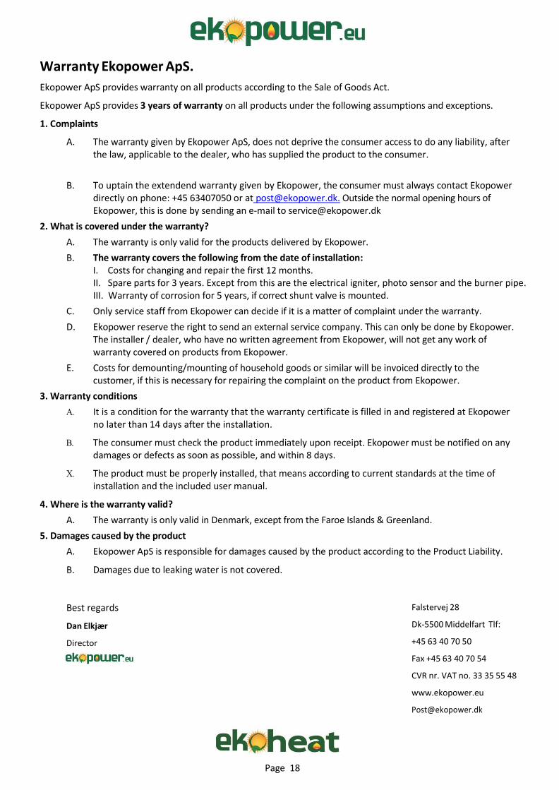
Warranty Ekopower ApS.
Ekopower ApS provides warranty on all products according to the Sale of Goods Act.
Ekopower ApS provides 3 years of warranty on all products under the following assumptions and exceptions.
1. Complaints
A. The warranty given by Ekopower ApS, does not deprive the consumer access to do any liability, after the law, applicable to the dealer, who has supplied the product to the consumer.
B. To uptain the extendend warranty given by Ekopower, the consumer must always contact Ekopower directly on phone: +45 63407050 or at [email protected]. Outside the normal opening hours of Ekopower, this is done by sending an e-mail to [email protected]
2. What is covered under the warranty?
A. The warranty is only valid for the products delivered by Ekopower.
B. The warranty covers the following from the date of installation: I. Costs for changing and repair the first 12 months. II. Spare parts for 3 years. Except from this are the electrical igniter, photo sensor and the burner pipe. III. Warranty of corrosion for 5 years, if correct shunt valve is mounted.
C. Only service staff from Ekopower can decide if it is a matter of complaint under the warranty.
D. Ekopower reserve the right to send an external service company. This can only be done by Ekopower. The installer / dealer, who have no written agreement from Ekopower, will not get any work of warranty covered on products from Ekopower.
E. Costs for demounting/mounting of household goods or similar will be invoiced directly to the customer, if this is necessary for repairing the complaint on the product from Ekopower.
3. Warranty conditions
It is a condition for the warranty that the warranty certificate is filled in and registered at Ekopower no later than 14 days after the installation.
The consumer must check the product immediately upon receipt. Ekopower must be notified on any damages or defects as soon as possible, and within 8 days.
The product must be properly installed, that means according to current standards at the time of installation and the included user manual.
4. Where is the warranty valid?
A. The warranty is only valid in Denmark, except from the Faroe Islands & Greenland.
5. Damages caused by the product
A. Ekopower ApS is responsible for damages caused by the product according to the Product Liability.
B. Damages due to leaking water is not covered.
Best regards
Dan Elkjær
Director
Falstervej 28
Dk-5500 Middelfart Tlf:
+45 63 40 70 50
Fax +45 63 40 70 54
CVR nr. VAT no. 33 35 55 48
www.ekopower.eu
Page 19
.Ji a. i;.s - ((.I.Hl .Ji ZP"!:TTl.Ji i:iC: •'i:"iZ':IZll) ib1 '[:. li:bli1 .- 1Y.' ll'[Cll i:.c: ·iZ':IZll)
Td.:') SI .;..;. - T11. : S1 S:i .:i.:i
E C CONFORMITY DE CLARATION
D OMUi:A CALEFACCIDN S.C 0 Ol'." i;:i.rili. V A.T. ESF-20000184" i'.l.iftess B-=- Sm
E5-æbms.h 2ffl-s7 Regi]. ( O"'.L ) SP...6.IN" csthll.tlE 11DdJ.ct
EK OHEAT 900 EK OHEAT 1500
EK OHEAT 2500
EK OHEAT 4000
M:tdi:ine: DndRie .'3'1/CE
stuvl.-.1. EN 3ffi-:5 ffiM±ng oo:ilm fir solii mls.. hind M"Ld.
i'.llltDin. i'.lti.c illy stDhd.. rom.naJ. he i'.11 Cl.llp1i a. 'I' to
300 h:W.
LVD : DndRie 2(1CtiØ :51CE EN 0033:5-1 ENtiffi3:5-2-3(1 EN 0033:5-2-:51, EN:5(1lti:5
EMC: DndRie 2(1CLfA ICE stuvl.-.1. EN :5:5(1U
P.J.l DOMUi:A CALEFACCIDN S.C 0 Ol'. profu:ti:m processes m ini'J.Ccordm.ce the
Qua1itj .hS1.nlU:e St.mmd.EN-IS 0 fil .
))13-09" 19
1 1

Page 20

Page 21

Page 22

Page 23
We do hope that you have got a good profit from this manual. Should
you have further questions please do not hesitate to contact us at