Embed Size (px)
Citation preview
User manual for optimus sound level
meters

optimus sound level meter user manual
Page 2
optimus sound level meter user manual
Page 3
About this manual
• The instructions in this user manual refer to the operation of Cirrus Research plc optimus sound level meters with version 2.4 or higher of the firmware.
• The instruments described in this manual are the optimus yellow (CR:150 series), optimus red (CR:160 series), optimus green (CR:170 series) and optimus purple (CR:190 series).
• Some functions described in this manual are only available on red or green versions of the optimus sound level meters. Where functions are applicable to only some instruments in the range, this will be clearly indicated in the text.
• In this manual, “optimus” is used as a general reference for the optimus sound level meters and “calibrator” is used as a general reference for an acoustic calibrator.
• This manual describes the recommended usage of the optimus. Any warnings will be indicated by
• The additional information required for testing in accordance with IEC 61672 is provided as a supplementary document, Optimus Sound Level Meters Technical Data Part B, which is available for download at www.cirrusresearch.co.uk/library/optimus
• It is not possible to change the way that the instrument measures through the software or firmware. Any legal metrology aspects of the instrument cannot be affected by any changes made in the instrument.
• The Common Specifications section on page 30 defines which standards relate to the different functions available in the instruments. Additional approvals and certifications may apply to the instruments and these will be listed in the Appendices.
• More detailed explanations of the audio recording templates, tonal noise detection and the repeat measurement timers are available to download from the Cirrus website at www.cirrusresearch.co.uk/library/optimus
• Quick Start Guides for the optimus sound level meters can be downloaded from the Cirrus website at www.cirrusresearch.co.uk/library/optimus
optimus sound level meter user manual
Page 4
Copyright
Copyright © Cirrus Research plc 2010-2013
All rights reserved.
You may re-use this document/publication (not including the Cirrus Research plc logo and other product logos) free of charge in any format for research, private study or internal circulation within an organisation. You must re-use it accurately and not use it in a misleading context.
You must not modify text, images or illustrations in any way. The material must be acknowledged as Cirrus Research plc copyright and you must give the title of the source document/publication.
Where any third party copyright material is identified you will need to obtain permission from the copyright holders concerned.
Trademarks
Cirrus Research plc, the Cirrus Research plc Logo, doseBadge, DOSEBADGE, optimus, the NoiseTools Logo and the Noise-Hub Logo are either registered trademarks or trademarks of Cirrus Research plc in the United Kingdom and/or other countries. Microsoft and Windows are registered trademarks of Microsoft, Inc. All other trademarks acknowledged.
Updates
In the interests of continuous product improvement, Cirrus Research plc reserves the right to make changes to product specifications without notice.
To understand the latest updates that have been implemented into this product and to download the most current version of this user manual, visit our web site at www.cirrusresearch.co.uk
Issue 2.2 February 2013 optimus/12/13/22EN
optimus sound level meter user manual
Page 5
Introduction ................................................................................................................................ 8
First Use .................................................................................................................................... 10
Inserting the batteries ....................................................................................................................... 12
Calibration.......................................................................................................................................... 13
Making a measurement ............................................................................................................ 15
Operations in more detail ......................................................................................................... 16
NoiseTools ......................................................................................................................................... 16
Keypad and Controls.......................................................................................................................... 16
Connectors......................................................................................................................................... 17
Screen saver ...................................................................................................................................... 18
Display ............................................................................................................................................... 18
Audio Recording ................................................................................................................................ 20
Timers ................................................................................................................................................ 21
Back Erase/Pause............................................................................................................................... 21
Memory ............................................................................................................................................. 22
Restore Factory Settings .................................................................................................................... 22
Windshield ......................................................................................................................................... 22
Getting to know your optimus – features and capabilities ...................................................... 23
Views ................................................................................................................................................. 23
High Level Noise Measurement ......................................................................................................... 25
Menus ....................................................................................................................................... 26
Additional Information .............................................................................................................. 29
Appendices ............................................................................................................................... 30
IEC 61672 test data ............................................................................................................................ 30
Common Specifications...................................................................................................................... 30
Views ................................................................................................................................................. 32
Stored Measurements ........................................................................................................................ 35
Electrical Outputs ............................................................................................................................... 37
Acoustic Calibrator Information ................................................................................................ 40
Calibrating a Sound Level Meter. ....................................................................................................... 40
Changing the Battery ......................................................................................................................... 41
Specifications ..................................................................................................................................... 42
Technical Information ........................................................................................................................ 42
CE Certificate of Conformity ...................................................................................................... 44
Warranty ................................................................................................................................... 45
Index ......................................................................................................................................... 46
Cirrus Research Offices ............................................................................................................. 47
optimus sound level meter user manual
Page 6
Start Calibrate
07/01/10 09:43:21
140
20LAS
Menu
Leq View
1 of 3
LAeq,1s dBLC Peak 89.3dBC-A 3.5dB
Short LAeq LCPeak
140
20
60
100
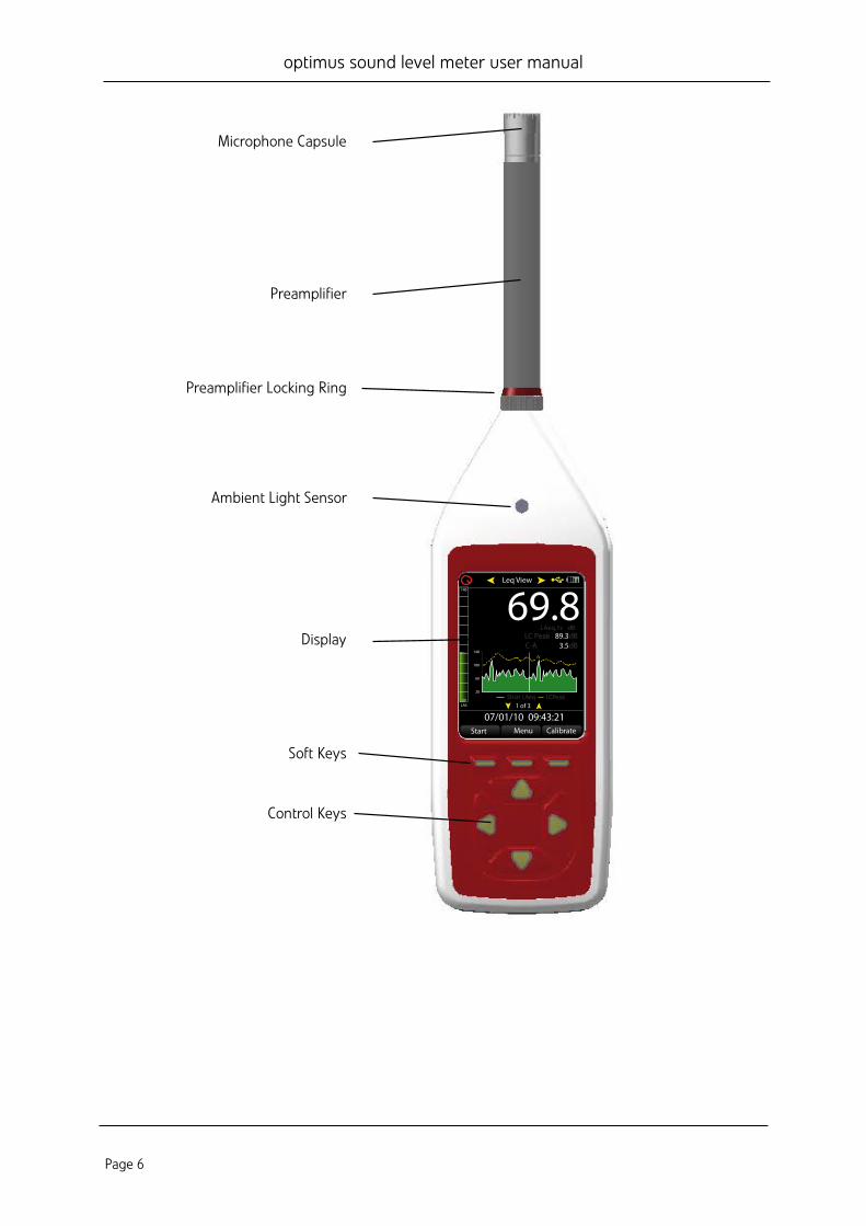
Microphone Capsule
Preamplifier
Ambient Light Sensor
Display
Soft Keys
Control Keys
Preamplifier Locking Ring
optimus sound level meter user manual
Page 7
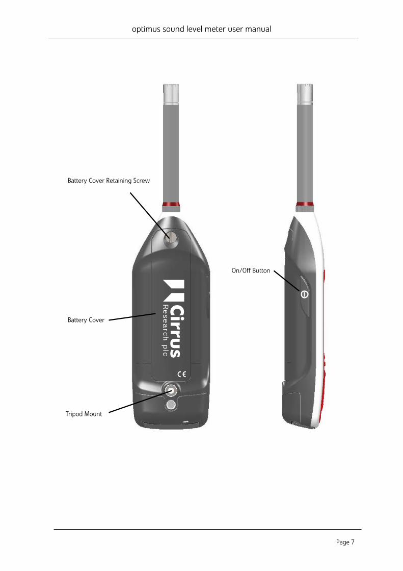
Battery Cover Retaining Screw
Cirru
sR
ese
arch
plc
Battery Cover
Tripod Mount
On/Off Button

optimus sound level meter user manual
Page 8
Introduction Welcome to your optimus sound level meter. This next-generation instrument from Cirrus Research plc is powerful yet simple to use, and is capable of a wide range of noise measurement functions.
The advanced technology used in the optimus instruments does not get in the way of you making effective noise measurements, and the large, clear screen makes it easy to read the comprehensive information on the display.
The optimus makes your noise measurements simple:
Measure everything and forget nothing
One of the key aims of the optimus instruments is to give you a sound level meter that is as simple to use as possible whilst providing the very highest level of performance and function.
You cannot forget to measure the right function as everything is measured at the same time.
For example, if you’ve chosen the Fast time weighting View Option, the optimus will still measure Slow and Impulse at the same time.
You can choose another time weighting View Option from the menu, and then see real-time data or review stored measurements using the new parameters.
This applies to all other noise parameters (excluding Dose - for further details, see page 25).
The optimus measures them all, and you can choose your View Option to review the data.
VoiceTag audio recording
The data logging versions of the optimus feature the VoiceTag audio recording function.
optimus sound level meter user manual
Page 9
This allows you to record notes and information before a measurement by simply speaking into the microphone, then play them back later in the NoiseTools software.
You can save time when making measurements, and remove the need to carry a notepad and store any important information about your measurements.
A single measurement range
By using the very latest in digital technology combined with 40 years’ experience in designing sound level meters, we have given the optimus instruments the ability to measure from 20dB(A) to 140dB(A) and up to 143dB(C) Peak in a single span.
This means that there is no need for you to choose which range you may need for your measurement, and that there is almost no chance of the instrument overloading or under-ranging.
A clear, simple display of the information you need
The display used on the optimus is a high resolution colour OLED type. This gives a clear, bright display that is easy to read in all light conditions as well as allowing us to use colour to show specific functions and information.
All of the information that you need is shown clearly on the screen with the most useful function, for example the Leq in the Leq View, shown in large white text. This makes it easy for you to see the information that is important at a glance.
A modular design to future proof your investment
The optimus instruments are based around a modular design which allows you to upgrade and update your instrument if and when the time arises.
This means that your instrument will meet your current and future needs, no matter what you need to measure.
Audio Recording during measurements
The optimus green instruments can record and store audio data (the actual sounds heard by the microphone) during a measurement.
This data can be downloaded along with the noise measurements for analysis and review and can be used to identify the source of the noise.
Audio recordings can be started either manually or automatically using a set of triggering rules.
optimus sound level meter user manual
Page 10
First Use Your optimus sound level meter has been shipped in reusable packaging that should be retained for safe shipment when returning the instrument for calibration or servicing.
All optimus meters come with the following standard accessories:
• MV:200 Microphone Preamplifier • Microphone capsule (attached to the preamplifier) • Wrist • 4 x AA batteries • User Manual • Product CD (with NoiseTools software and documentation) • Windshield
You may have other accessories, depending on your package. Please check for damage or missing items before using your optimus.
All optimus instruments are shipped with the removable preamplifier separated from the body. When connecting the preamplifier, please take great care to only turn the locking ring at the base.
Twisting the preamplifier body is likely to cause serious damage. The microphone capsule is also delicate, and care needs to be taken when handling.
Damage caused by misuse is not covered by the warranty for the instrument.
optimus sound level meter user manual
Page 11
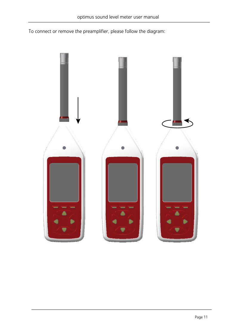
To connect or remove the preamplifier, please follow the diagram:
optimus sound level meter user manual
Page 12
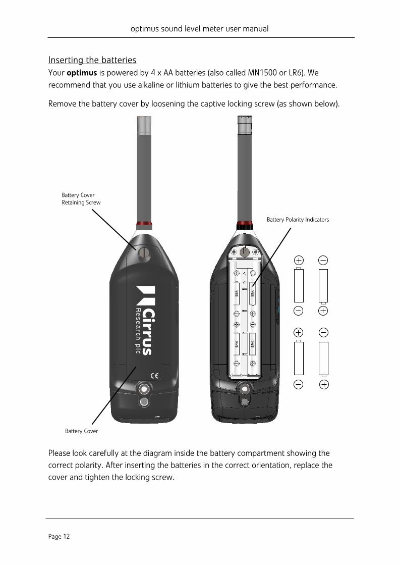
Inserting the batteries Your optimus is powered by 4 x AA batteries (also called MN1500 or LR6). We recommend that you use alkaline or lithium batteries to give the best performance.
Remove the battery cover by loosening the captive locking screw (as shown below).
Please look carefully at the diagram inside the battery compartment showing the correct polarity. After inserting the batteries in the correct orientation, replace the cover and tighten the locking screw.
Battery CoverRetaining Screw
Battery Cover
Battery Polarity Indicators
Cirru
sR
ese
arch
plc
optimus sound level meter user manual
Page 13
The instrument is switched on by pressing and releasing the power button on the left hand side of the case. After the boot screen, your optimus will display the last View you used.
Calibration All noise measuring instruments should be calibrated before each use, because the microphone is susceptible to minor damage from even small knocks.
The calibration applies corrections (if needed) to ensure that your measurements are as accurate as possible.
Calibration should also be carried out at the end of a measurement session to make sure that nothing has happened to the instrument during the session.
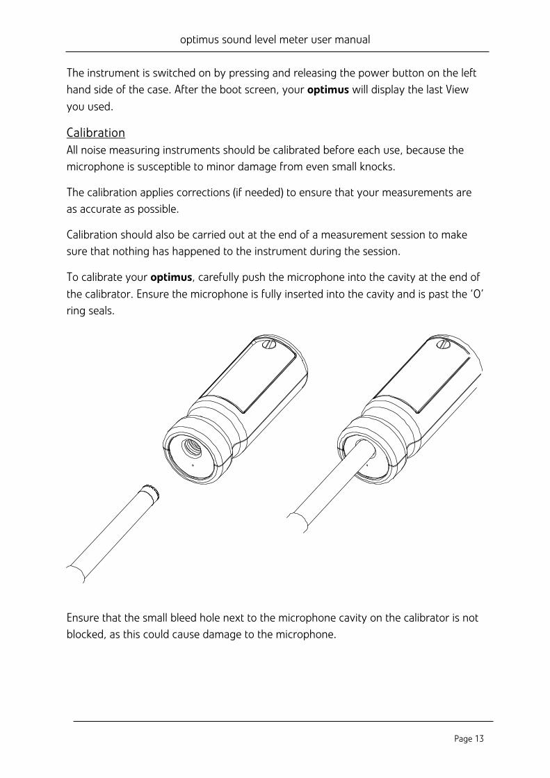
To calibrate your optimus, carefully push the microphone into the cavity at the end of the calibrator. Ensure the microphone is fully inserted into the cavity and is past the ‘O’ ring seals.
Ensure that the small bleed hole next to the microphone cavity on the calibrator is not blocked, as this could cause damage to the microphone.
optimus sound level meter user manual
Page 14
Take care not to use a twisting motion when pushing the microphone into the calibrator, as this is likely to cause damage to the preamplifier (as described earlier in this chapter).
Press the ‘on’ button on the end of the calibrator. Press the calibrate button on the optimus.
The instrument will measure the sound level from the acoustic calibrator to determine if it is within the required tolerance and levels. The calibration level must be stable to within ±0.075dB for 5 consecutive seconds for the calibration to be successful.
When the calibration is completed, the optimus will display the level along with the correction or adjustment made.
The optimus is preset with the correction values needed for Cirrus Research microphone capsules, so no manual adjustment is required. The calibration level you should expect is 93.7dB.
Refer to page 40 for detailed operating information for the CR:514 and CR:515 Acoustic Calibrators.
optimus sound level meter user manual
Page 15
Making a measurement Press the Start key to begin recording (on data logging intruments with the VoiceTag function switched on, the VoiceTag screen will show – press skip to move on without recording a note).
Your optimus is now measuring and recording noise data for all available functions, regardless of your selected View, and the red animated Running icon will show in the top left of the information bar.
The measurement can be paused by pressing the Pause/Stop soft key .
Press once to pause/back erase and twice to stop, or alternatively press and hold for three seconds to stop. (For Pause & Back Erase, see page 21).
The Pause/Back Erase function is only available if this has been enabled in the instrument menu.
To stop the measurement, press the Stop key. The instrument will change from measurement to review mode, and your data is stored and ready to review and download. For instruments without data logging, only the last recorded measurement is available for review.
optimus sound level meter user manual
Page 16
Operations in more detail Please note: from this chapter on, the manual describes capabilities which are available on different models within the optimus range.
If you are unsure which capabilities your optimus has, you can check on the instrument by looking at the General View / page 5 (and 6 on
some models), or look at the Features Matrix available on the Cirrus Research website: www.cirrusresearch.co.uk/optimus/library
NoiseTools All optimus instruments are delivered with a copy of the NoiseTools software which can be used to configure the instrument (some options are only configurable within NoiseTools and not on the instrument – it will be made clear in the text where this is the case).
NoiseTools is also a powerful environment for storing, analysing and organising your data, and produces reports for publication. VoiceTag notes and audio recordings can only be played back through NoiseTools.
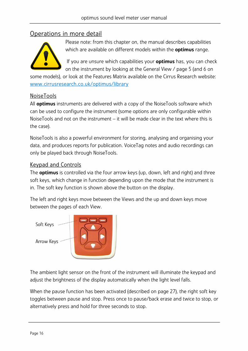
Keypad and Controls The optimus is controlled via the four arrow keys (up, down, left and right) and three soft keys, which change in function depending upon the mode that the instrument is in. The soft key function is shown above the button on the display.
The left and right keys move between the Views and the up and down keys move between the pages of each View.
The ambient light sensor on the front of the instrument will illuminate the keypad and adjust the brightness of the display automatically when the light level falls.
When the pause function has been activated (described on page 27), the right soft key toggles between pause and stop. Press once to pause/back erase and twice to stop, or alternatively press and hold for three seconds to stop.
optimus sound level meter user manual
Page 17
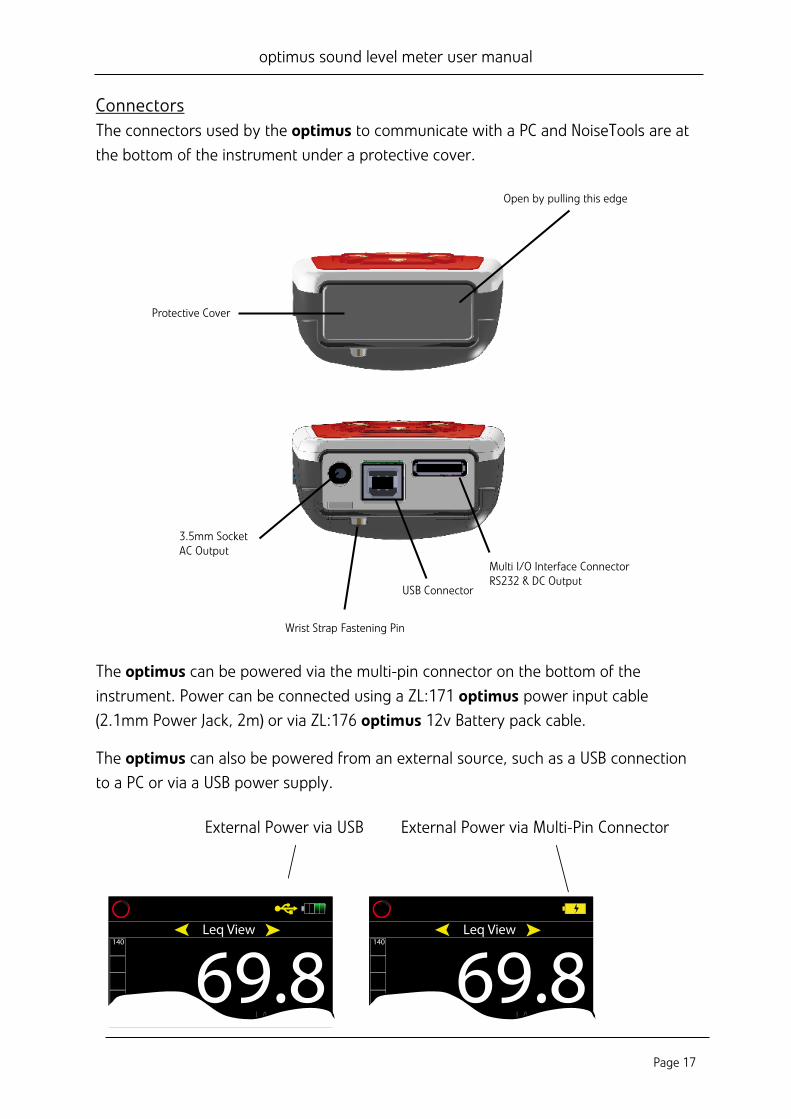
Connectors The connectors used by the optimus to communicate with a PC and NoiseTools are at the bottom of the instrument under a protective cover.
The optimus can be powered via the multi-pin connector on the bottom of the instrument. Power can be connected using a ZL:171 optimus power input cable (2.1mm Power Jack, 2m) or via ZL:176 optimus 12v Battery pack cable.
The optimus can also be powered from an external source, such as a USB connection to a PC or via a USB power supply.
Protective Cover
Open by pulling this edge
USB Connector
Multi I/O Interface ConnectorRS232 & DC Output
3.5mm SocketAC Output
Wrist Strap Fastening Pin
140
Leq View
LAeq,1s dBLC Peak 89.3dBC-A 3 5dB
140Leq View
LAeq,1s dBLC P k 89 3dB
External Power via USB
140
Leq View
LAeq,1s dBLC Peak 89.3dBC-A 3 5dB
140Leq View
LAeq,1s dBLC P k 89 3dB
External Power via Multi-Pin Connector
optimus sound level meter user manual
Page 18
An AC output is available on the optimus via the 3.5mm jack socket. The output is un-weighted and the output level can be adjusted using the options in the AC Out menu.
This output can be used with external instrumentation. See page 37 for details of the electrical outputs.
Screen saver If no keys are pressed for 6 minutes the display will dim to preserve battery and screen life, and reduce power consumption. After 30 minutes with no key presses the display will switch off completely and keypad flashes every two seconds to show that the instrument is powered. The screen dim and screen saver functions will occur during measurements as well as when not measuring. Press any key to restore the display.
The time intervals for the screen dim and screen saver are configurable in NoiseTools.
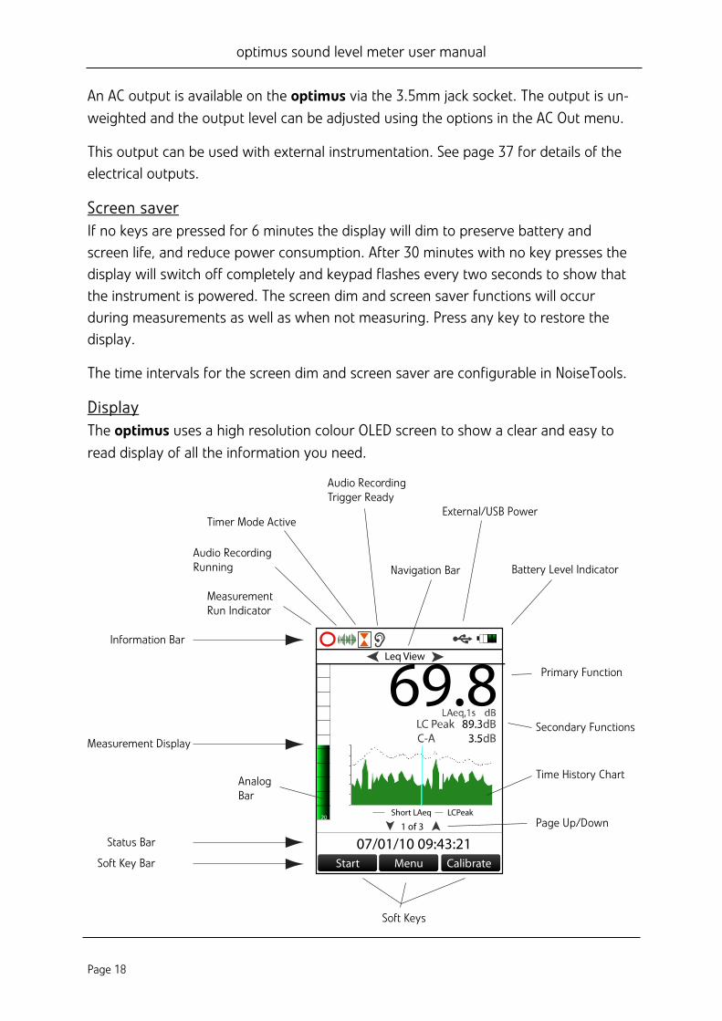
Display The optimus uses a high resolution colour OLED screen to show a clear and easy to read display of all the information you need.
Audio RecordingRunning
Timer Mode ActiveExternal/USB Power
Navigation Bar
Information Bar
Measurement Display
MeasurementRun Indicator
Battery Level Indicator
Primary Function
Secondary Functions
Time History Chart
Page Up/Down
Soft Keys
AnalogBar
Status Bar
Soft Key Bar
Audio RecordingTrigger Ready
Start Menu Calibrate
1 of 3
07/01/10 09:43:21
Leq View
Short LAeq LCPeak
optimus sound level meter user manual
Page 19
Information Bar The information bar shows icons when functions are active. Examples of the icons are shown in the diagram above.
Navigation Bar The navigation bar shows which View or Menu you are looking at.
Measurement Display In addition to primary and secondary functions, the display features an Analog Bar on the left of the screen, which shows real time A-weighted sound level. At the bottom of the screen is the Page information for your View, ie 1 of 3.
Status Bar When the optimus is not measuring, the status bar shows the date and time. When it is measuring, the display shows the elapsed time and in Review mode it shows the measurement number and the total number of measurements stored.
Overload and Under-Range Indication Overload is indicated by the word 'overload' and Under-Range is indicated by the word ‘under range’ (in the chosen language) on the display.
On the Sound Level View and Leq View the indicators are situated beneath and to the left of the large number. When a measurement is not in progress, the indicator is shown for at least 1 second, so that very short transient overload or under-range conditions are visible to the operator.
When a measurement is in progress, the overload indicator stays on until the measurement is stopped or reset.
In some circumstances the overload and under range indicators will be shown simultaneously. In this case the text will be abbreviated to save space.
Note that if any displayed decibel value on the Sound Level View or Leq View is below 14.0dB, the value will be replaced by dashes ('---'). These levels are typically below the noise floor of the microphone capsule and so will only be encountered during electrical testing.
‘Bluescreen’ Under rare circumstances, when the optimus encounters a condition it cannot recover from, a ‘bluescreen’ error message will show with an error code. If this should happen to your optimus, please make a note of the code so the engineers at Cirrus Research
optimus sound level meter user manual
Page 20
can diagnose your problem accurately. After writing down the code, pressing the right key will clear the screen and the instrument can be used as normal.
Battery indicator The status of the batteries is shown in the Battery Level Indicator. When the batteries need replacing, the indicator will turn red.
Low Battery Indication while switching on If the start-up screen flashes quickly when you press the on button, the batteries have insufficient power to start and need changing.
Audio Recording Audio recording can be started automatically using the Audio Triggers or manually using the Audio soft key.
This starts the optimus recording raw WAV data at a quality which can be set in the Menu (Standard or Studio).
Details of the Audio Triggers can be found in Technical Note 28 - Audio Recording with the optimus green sound level meters. Please refer to the Cirrus Research plc website at www.cirrusresearch.co.uk/library/optimus.
Pressing the audio key again stops the recording. There is no maximum duration of an audio recording set by default, but it can be changed in NoiseTools, and the parameters for the Audio Triggers can be configured in NoiseTools.
The audio recording includes a 10 second back buffer (on the Standard quality setting). When triggering a recording manually, it’s very difficult to record the beginning of a sound that catches your attention.
The back buffer will cover the time it takes you to respond and press ‘record’. 10 seconds is the default duration, which can be changed in NoiseTools.
The Time History display and Analog bar turn blue when audio recording is running and revert to green when it is stopped.
Starting and stopping audio recording during a measurement does not affect the noise measurement data being recorded.
Please note, VoiceTags are recorded BEFORE the measurement starts and are for spoken notes only, not for analysis of recorded sounds.
optimus sound level meter user manual
Page 21
Timers The single and repeat timers allow you to make precisely timed measurements over pre-set or custom defined durations, which are set on the instrument using the Storage Options Menu (see next chapter).
The repeat timer allows measurements to be stopped and started automatically over a long period of time. The optimus can still be stopped and started manually when the repeat timer is active.
The repeat timer is synchronised to the real time clock, so if you choose a 30 minute duration the measurement will begin on the hour or at 30 minutes past. When the measurement ends, a new one will begin and last for the next 30 minute interval.
If the optimus is paused when an automatic timer begins, the new timed measurement will also be paused.
Please note, after 5 minutes in pause the optimus will restart.
Back Erase/Pause
Pause The optimus sound level meters provide Pause and Back Erase function which can be used during a measurement.
When the Pause function is enabled in the menu, the Stop button is replaced by the Pause/Stop button. This also enables the Back Erase function, the duration of which can be set in the menu.
Back Erase The Back Erase function allows a section of the measurement to be removed from the data used to calculate the overall values.
An example of this would be if, during the measurement of cars on a road, a large truck passed by the measurement location. If the intention was only to measure cars, the truck can be excluded from the overall measurement data by pressing the Pause button and then using the Back Erase to remove a preset section of noise.
The time that the pause button was pressed, along with the Back Erase duration, will be excluded from the calculation of the overall noise values such as the Leq, Lmin, Lmax, LPeak, and the 1:1 and 1:3 Octave Band overall values.
optimus sound level meter user manual
Page 22
The duration of the Back Erase can be set to between 1 and 30 seconds using the menu and can also be configured in the NoiseTools software. If the Pause function is disabled, the Back Erase function is also disabled.
Memory The optimus has a 4GB memory as standard. This is partitioned into two sections, one to record time history and one for audio (VoiceTags and audio recordings). The space allocated to each can be configured in NoiseTools.
The free space in the memory is shown in the General View as days or hours available for both time history and audio. When either partition is full, the optimus will overwrite the oldest data in that partition.
To clear the memory and permanently delete all stored data, choose the ‘Clear Memory’ Menu page and follow the instructions on screen. Before permanently erasing the data, you will be asked to press ‘OK’ to confirm.
Restore Factory Settings This is in the Advanced Options Menu, and restores the optimus to the default options for all user-definable settings in the Menus, and clears the calibration offset. For settings such as ‘language’ where there is no default, the optimus will return to the option it was shipped with.
Follow the instructions on the screeen, and press ‘OK’ to confirm.
This does not delete any stored measurements.
Windshield The optimus can be used with a UA:237 90mm foam windshield which will reduce the noise levels generated by air turbulence over the microphone capsule.
It can also help protect the microphone capsule from dust and fluids which can affect the performance of the instrument.
optimus sound level meter user manual
Page 23
Getting to know your optimus – features and capabilities The optimus instruments are designed around a modular structure that allows an instrument to be upgraded and updated with new capabilities (functions), protecting your investment for the future.
To check which capabilities your optimus has, go to General View / page 5 (and 6 on some models). This will list all the available capabilities. Alternatively, a Feature Matrix is available on the Cirrus Research website, which lists all the capabilities for all optimus models.
Some options cannot be changed while the optimus is measuring, and a message will appear on the screen telling you ‘cannot be changed while measuring’. Some menu choices are disabled while measuring, and will appear grey on the screen.
Views The views are accessed by pressing the left and right control keys. The views are available when the optimus is measuring, not measuring or in review mode, but the pages available in each mode will differ.
Not measuring When not measuring, the information shown is live, instantaneous values.
Measuring When measuring, these live values are still shown, but you are also shown cumulative overall values for the current measurement period.
Review Mode In review mode, the values shown are the overall cumulative values for the meaurement.
General View This shows the status of the instrument with the calibration data, the capabilities that are fitted, serial numbers of the instrument, microphone and preamplifier along with details of the standards that the instrument meets.
Sound Level View This view shows the Sound Pressure Level or SPL, with the maximum and minimum sound level (Lmax and Lmin) with a choice of A, C and Z frequency weightings.
optimus sound level meter user manual
Page 24
Leq View Shows you the Leq, Peak, LAE (SEL) and C-A values with a choice of A, C and Z frequency weightings.
The C-A data can be used with the HML method for selecting hearing protection.
If the Time Weighting is set to Impulse, the C-A function is replaced by LAeq,I (also known as LAIeq).
When the instrument is set to the German language, an additional ‘Taktmaximal’ page is also available.
1:1 Octave Band View This view shows the noise levels divided into Octave frequency bands. This can be used to aid in the selection of hearing protection and also for noise control applications.
Some models also have the capability to show NR & NC Curves and resultant values.
1:3 Octave Band View This view shows the noise levels divided into 1:3 Octave (called ‘third-octave’) frequency bands. This can be used for environmental noise measurements and also for noise control applications.
The 1:3 Octave Band View also provides Leq LF (20Hz-200Hz) and LAeq LF (20Hz-200Hz).
Tone detection This is a capability on some instruments, displayed within the 1:3 octave view.
Instruments with Tone Detection use either the ISO 1996-2:2007 Simplified Method or an improved method developed by Cirrus Research which is based upon the ISO standard, extended to include tones between bands, tones in outer bands and Z-weighting. The ISO method only applies to overall data when measuring or reviewing, whereas the Cirrus Improved Method also applies to instantaneous live values.
When a tone is detected, the band is highlighted in blue on both the graphical and numerical pages.
This can be set to the Cirrus Improved Method (default setting) or the ISO 1996 method in NoiseTools.
optimus sound level meter user manual
Page 25
For more information, please see Technical Note 32 - Tonal noise detection with the optimus sound level meters available for download from the Cirrus Research website at www.cirrusresearch.co.uk/library/optimus.
Ln View The Ln view shows the statistical Ln values calculated during the measurement. The first seven Ln values are set by default to commonly used values and 8-14 are definable in NoiseTools.
Some optimus models have a second set which are also 1-7 default, 8-14 user definable.
The source data type for the second Ln set is also configurable in NoiseTools.
Dose View The Dose View gives you a number of different functions depending upon the configuration of the Quick Settings.
For the UK option, this View gives you Leq, LEP,d, % Dose and Estimated Dose along with the Projected Exposure Calculator.
For the EU option, this View gives you Leq, LEX,8, % Dose and Estimated Dose along with the Projected Exposure Calculator.
For all other options the Lavg, TWA, % Dose and Estimated % Dose for two integrators, in addition to ISO (EU), will be shown according to the setting you have chosen.
Two custom integrators can also be used, configured in NoiseTools. When chosen, they will be shown in addition to ISO (EU).
Moving Average View The Moving Average View is available on the CR:191BE & CR:193BE instruments only. The Moving Average View shows a 15 minute and 60 minute moving average LAeq along with LASmax and LA95 values. The LAeq values are highlighted in colours under certain conditions. See page 25 for details of the trigger levels.
High Level Noise Measurement The optimus sound level meters can be used to measure high noise levels (up to 170dB) with the use of the optional MV:200EH High Level Noise Measurement Option.
optimus sound level meter user manual
Page 26
This consists of a microphone capsule, attenuator and preamplifier, supplied as a complete unit. Switch off the instrument before fitting the MV:200EH.
Once the unit is fitted, calibrate the sound level meter as standard. The optimus will detect the MV:200EH and adjust the measurement span to 50-170dB.
If the standard microphone and preamplifier are replaced, re-calibrate the optimus to return the measurement span to the standard 20-140dB range.
Menus In the following Menus, different options can be chosen on the optimus. To activate a function, press the ‘mark’ soft key to put a tick in the square box.
You can now use the up and down soft keys to select your setting, and use the ‘OK’ soft key to confirm it. In the menu pages, the Status Bar will display information about your current settings and the option you have chosen.
The following chapter shows the navigation between the Menus and Pages, and the options available. For more detailed information, please see the appendices.
Main menu Restart Review stored data Clear memory Advanced options View options Storage options Quick settings Set clock
Restart: Pressing Menu / Restart at any time during a measurement resets the elapsed time to zero, and deletes the data for that measurement only.
Review Stored data: Using the left and right keys moves between the different Views (see previous chapter for details) and the up and down keys move between the Pages of each View. The status bar will tell you which measurement you are looking at out of the total (for example Measurement 4 of 9).
Clear Memory: Permanently deletes all stored measurements.
optimus sound level meter user manual
Page 27
Advanced options: Restore Factory Settings Restores the instrument back to its original factory setup.
AC Out On/Off +20dB Gain High Levels (70-140dB) or Low Levels (20-90dB)
Audio Quality Standard Quality (16bit, 16kHz) Studio Quality (32bit, 96kHz)
Audio Triggers On/Off Default (75dB LAeq, No minimum time) – User adjustable on the optimus Select any user programmed triggering templates
Pause On/Off Back Erase Duration (0-30seconds)
Please note, after 5 minutes in pause the optimus will restart.
View options: Set level colours (Analog Bar) Defaults: 80dB = Yellow, 85dB =Red User selectable
Time Weighting Fast, Slow, Impulse
Adjust Screen Brightness Fixed, Auto (default)
Set date/time formats dd/mm/yy, mm/dd/yy, dd.mm.yy, dd-mm-yy, yy-mm-dd hh:mm:ss, hh:mm:ss AM/PM
Language English, Français, Deutsch, Español, Italiano Please note: when changing language, the instrument must be restarted for the change to take effect.
optimus sound level meter user manual
Page 28
Storage options: Time History Rate 2s, 1s (default), ½sec (500ms), ¼sec (250ms), 1/8sec (125ms) 1/16sec (62.5ms), 1/100sec (10ms)
VoiceTag On/Off
Single Timer On/Off 1min, 2min, 5min, 10min, 15min, 30min, 1hr, Custom (default 10min)
Repeat Timer On/Off 1min, 2min, 5min, 10min, 15min, 30min, 1hr, Custom (default 10min) Day/Evening/Night
Quick Settings: • UK • EU • OSHA HC and PEL • OSHA HC and ACGIH • MSHA HC and EC • Custom
Set Clock: Follow the instructions on the screen to set the date and time using the format set in View Options / Set Date and Time Format above.
optimus sound level meter user manual
Page 29
Additional Information Additional information on the following topics can be downloaded from the Cirrus Research website. Please visit www.cirrusresearch.co.uk/library/optimus for the latest versions of these documents.
• Technical Note 28 - Recording Audio with the optimus green (CR:170) sound level meters
• Technical Note 29 - Timer mode options • Technical Note 30 - Project Exposure Calculation • Technical Note 31 - NR & NC Curves
Other documents may also be available for the optimus sound level meters. Please visit the Cirrus Research website for the latest information.
optimus sound level meter user manual
Page 30
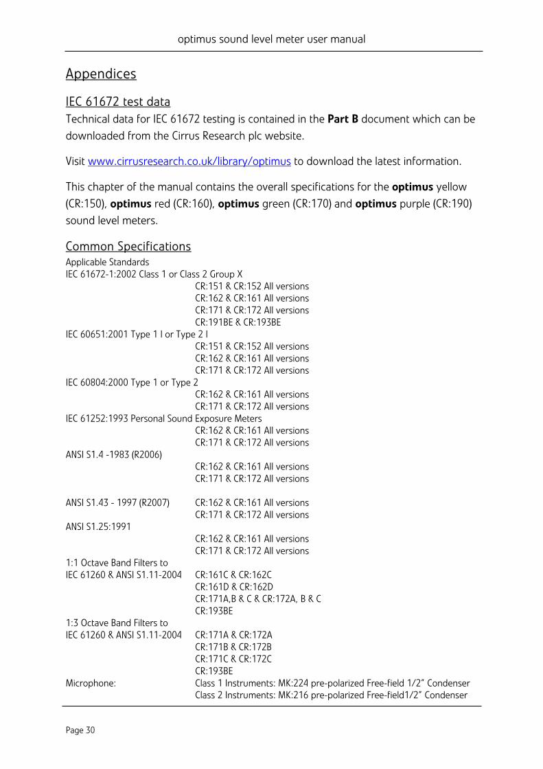
Appendices
IEC 61672 test data Technical data for IEC 61672 testing is contained in the Part B document which can be downloaded from the Cirrus Research plc website.
Visit www.cirrusresearch.co.uk/library/optimus to download the latest information.
This chapter of the manual contains the overall specifications for the optimus yellow (CR:150), optimus red (CR:160), optimus green (CR:170) and optimus purple (CR:190) sound level meters.
Common Specifications Applicable Standards IEC 61672-1:2002 Class 1 or Class 2 Group X CR:151 & CR:152 All versions CR:162 & CR:161 All versions CR:171 & CR:172 All versions CR:191BE & CR:193BE IEC 60651:2001 Type 1 I or Type 2 I CR:151 & CR:152 All versions CR:162 & CR:161 All versions CR:171 & CR:172 All versions IEC 60804:2000 Type 1 or Type 2 CR:162 & CR:161 All versions CR:171 & CR:172 All versions IEC 61252:1993 Personal Sound Exposure Meters CR:162 & CR:161 All versions CR:171 & CR:172 All versions ANSI S1.4 -1983 (R2006)
CR:162 & CR:161 All versions CR:171 & CR:172 All versions
ANSI S1.43 - 1997 (R2007) CR:162 & CR:161 All versions CR:171 & CR:172 All versions ANSI S1.25:1991 CR:162 & CR:161 All versions CR:171 & CR:172 All versions 1:1 Octave Band Filters to IEC 61260 & ANSI S1.11-2004 CR:161C & CR:162C CR:161D & CR:162D CR:171A,B & C & CR:172A, B & C CR:193BE 1:3 Octave Band Filters to IEC 61260 & ANSI S1.11-2004 CR:171A & CR:172A CR:171B & CR:172B CR:171C & CR:172C CR:193BE Microphone: Class 1 Instruments: MK:224 pre-polarized Free-field 1/2” Condenser Class 2 Instruments: MK:216 pre-polarized Free-field1/2” Condenser
optimus sound level meter user manual
Page 31
Microphone Preamplifier: MV:200 Removable Preamplifier for Class 1 & Class 2 instruments Total Measurement Range: 20dB to 140dB RMS Single Range Noise Floor: <18dB(A) Class 1, <21dB(A) Class 2 Frequency Weightings: RMS: A, C, & Z Measured Simultaneously Peak: A, C, & Z Measured Simultaneously Time Weightings: Fast, Slow & Impulse Measured Simultaneously Display: High resolution OLED (Organic Light Emitting Diode) display with ambient light sensor & illuminated keypad Display of: Measured parameters Recalled Measurement Parameters (Data Logging Versions)
Battery Level & External Power Connection Overload & Under Range Time & Frequency Weighting Elapsed Measurement Time Instrument status
Memory: 4GB as standard (Data Logging Versions) 32GB factory fitted option AuditStore: For each measurement, the following data is stored into an
independent, non-volatile memory for use with the AuditStore function:
Start Time, Duration, LAFMax, LAeq, LCPeak, L10, L90, Overload Calibration data, Diagnostic information.
Time History Data Rates (Global settings): 10ms, 62.5ms, 125ms, 250ms, 1/2 sec, 1 sec, 2 sec (User selectable) VoiceTag Audio Recording: User selectable recording of voice notes before each
measurement for download to NoiseTools software (Data Logging Versions)
30 seconds per recording with audio files downloaded with noise measurement information.
Size: 283mm x 65mm x 30mm Weight: 300gms/10oz Batteries: 4 x AA Alkaline Battery life: Typically 12 hours with Alkaline Batteries
Typically 20 hours with Lithium AA Non-Rechargeable Batteries Battery life is dependent upon the battery type and quality and screen
brightness External Power: 5v via USB Socket from PC or Power Supply 5v-15v via MultiIO socket Tripod Mount: 1/4” Whitworth socket Connections: USB Type B to PC Multi-pin IO for external power 3.5mm Stereo Jack for AC output Case Material: High Impact ABS-PC with soft touch back & keypad Environmental: Temperature Operating: -10°C to +50°C Storage: -20°C to +60°C Humidity: Up to 95% RH Non Condensing Electromagnetic performance: IEC 61672-1:2002 IEC 61672-2:2003 Except where modified by EN 61000-6-1:2007 & EN 61000-6-1:2007 Language options: English, French, German, Spanish and Italian. Software Support: NoiseTools Download, Configuration & Analysis software as standard.
Compatible with Microsoft Windows XP, Vista. Windows 7 & Windows 8 (32bit & 64bit)
optimus sound level meter user manual
Page 32
Views
Sound Level View • Sound Level: Lxy, x=A ,C ,Z; y= F, S, I • Maximum Sound Level: LxyMax where x=A ,C ,Z; y= F, S, I • Minimum Sound Level: LxyMin where x=A ,C ,Z; y= F, S, I • Measurement Run Time
Leq View • Lxeq where x = A ,C, Z • LCPeak, LZPeak, • LCeq-LAeq, • LxE where x = A ,C, Z • LAeq,I (Also known as LAIeq,t) - replaces LCeq-LAeq when Impulse Time Weighting
is selected) • Graphical: Short LAeq, LCPeak • Measurement Run Time • Taktmaximal levels and integrated levels, and 3 and 5 seconds, Fast and Impulse
time weighted.
1:1 Octave Band View • Graphical display of LF real time octave bands with the highest value for each band
(updated every 1/16 seconds) from 32Hz to 16kHz (16Hz 1:1 Octave Band stored for display in the NoiseTools software)
• Graphical display of cumulative Leq for each octave band • Graphical display of cumulative LAeq for each octave band • Numeric display of Leq,1s real time octave bands (updated every 1 second) • Numeric display of cumulative Leq for each octave band • Numeric display of cumulative LAeq for each octave band • Measurement Run Time
1:3 Octave Band View • Graphical display of LF real time 1:3 octave bands with the highest value for each
band (updated every 1/16 second) from 12,5Hz to 20KHz (6.3Hz, 8Hz and 10Hz 1:3 Octave Bands stored for display in NoiseTools)
• Graphical display of cumulative Leq and LAeq for each band
optimus sound level meter user manual
Page 33
• Graphical display of cumulative LAeq for each band • Numeric display of Leq, 1s real time bands (updated every 1 second) • Numeric display of cumulative Leq and LAeq for each band • LeqLF and LAeqLF (20Hz to 200Hz) • Instruments with Tone Detection Capability display tonal bands in blue.
Ln View Measures and stores statistical values during measurements Provides 14 Ln values to 0.1dB resolution
• L1.0 • L5.0 • L10.0 • L50.0 • L90.0 • L95.0 • L99.0
Lns 7-14 are user defined, turned off by default.
Ln values are calculated using 1/16 second LAF samples by default. Sampling rate, time weighting and frequency weighting can be changed in NoiseTools.
Instruments with the “Statistical Levels x 2” Capability provide a second set of 14 Ln values which can be configured within NoiseTools using independent sampling rate, time weighting and frequency weighting.
Dose View Integrator 1 Integrator 2 Integrator 3
Run Time Run Time Run Time Leq1 Leq2 Leq3 LEP,d (Lex) TWA TWA Dose % Dose % Dose % Est Dose % Est Dose % Est Dose % Configuration Configuration Configuration
Measurement Run Time
optimus sound level meter user manual
Page 34
Moving Average View • Page 1 • LAeq,15min
o Indicated in Red where LAeq,15min > 95dB, o Indicated in Yellow where LAeq,15min > 85 dB o Indicated in White where LAeq,15min < 85dB
• LASMax • LA95
• Page 2 • LAeq,60min
o Indicated in Red where LAeq,60min > 100dB o Indicated in White where LAeq,60min < 100dB
• LASMax • LA95
optimus sound level meter user manual
Page 35
Stored Measurements
Sound Level View • Overall: LxyMax where x = A, C, Z; y = F, S, I (9 items). • Time History: LxyMax where x = A, C; y = F, S,I (6 items). • Time History: LxyMin where x = A, C; y = F, S,I (6 items). • Measurement Run Time • Time & Date of Measurement Start • Time History data rate is user configurable in the global settings
Leq View • Overall: LCPeak, LZPeak. LAeq, LCeq, LZeq (5 items). • Time History: LAeq, LCeq, LZeq • Time History: LCPeak, LZPeak, LAPeak • Time History: LAeqI (also known as LAIeq,t) • Time History data rate is user configurable in the global settings • Measurement Run Time • Time & Date of Measurement Start
Dose View • Overall: LAeq2, LAeq3. (Lavg stored, TWA, % Dose & Est % Dose also available) • Time History: LAeq2, LAeq3 • Time History data rate is user configurable in the global settings • Measurement Run Time • Time & Date of Measurement Start • Integrator 1 values are stored in the Leq module
1:1 Octave Band View • Overall Leq for each octave band • Overall LAeq for each octave band • NR & NC values (CR:160 D version, CR:170 A,B & C versions) • Time History: Leq for each octave band. (10 items) stored at the Global data rate
(minimum duration of 1/16 seconds) • Measurement Run Time • Time & Date of Measurement Start
optimus sound level meter user manual
Page 36
1:3 Octave Band View • Overall Leq for each octave band 36 items for 6.3Hz to 20kHz • Overall LAeq for each octave band 36 items for 6.3Hz to 20kHz • Leq,LF & LAeq,LF (20Hz to 200Hz) • Time History: Leq for each 1:3 octave band. 36 items for 6.3Hz to 20kHz stored at
the Global data rate (minimum duration of 1/16 seconds) • Measurement Run Time • Time & Date of Measurement Start
Ln View • 14 Ln values for each measurement in Ln set #1 • 14 Ln values for each measurement in Ln set #2 (CR:171C & CR:172C)
Moving Average View • Page 1
o LASMax o LA95
• Page 2
o LASMax o LA95
optimus sound level meter user manual
Page 37
Menu / Quick Settings The Quick Settings available are:
UK: 3dB, No Threshold, No Time Weighting, Criterion Level of 85dB
EU: 3dB, No Threshold, No Time Weighting, Criterion Level of 85dB
OSHA HC & PEL Integrator 2: 5dB, 80dB Threshold, Slow Time Weighting, 90dB Criterion Level Integrator 3: 5dB, 90dB Threshold, Slow Time Weighting, 90dB Criterion Level
OSHA HC & ACGIH Integrator 2: 5dB, 80dB Threshold, Slow Time Weighting, 90dB Criterion Level Integrator 3: 3dB, No Threshold, Slow Time Weighting, 85dB Criterion Level
MSHA HC & EC Integrator 2: 5dB, 80dB Threshold, Slow Time Weighting, 90dB Criterion Level Integrator 3: 5dB, 90dB Threshold, Slow Time Weighting, 90dB Criterion Level
Custom Custom settings defined by the NoiseTools software
Electrical Outputs
AC Output The AC Output is provided on the 3.5mm jack socket at the bottom of the instrument.
Do not use a Stereo Jack Plug in this socket. Only use a 3.5mm Mono Jack Plug.
The AC output has four settings: a combination of High or Low levels and a 0 or +20dB amplifier.
Voltages and full scale levels are as follows:
High Levels (70-140dB): 0dB gain 1.3V pk-pk (450mV rms) at full scale 140dB +20dB gain 1.7V pk-pk (600mV rms) at full scale 132dB
Low Levels (20-90dB): 0dB gain 400mV pk-pk (140mV rms) at full scale 90dB +20dB gain 1.3V pk-pk (450mV rms) at full scale 90dB
The output is unweighted, i.e. Z-weighted.
optimus sound level meter user manual
Page 38
AC Output Cables The AC Output should be used with a ZL:174, ZL:177 or ZL:185 Cable.
These cables are available from Cirrus Research plc or your local distributor. Do not use any other cable with the optimus. This may damage the instrument and invalidate your warranty.
DC Output The DC Output is provided on the 18 Pin Multi-IO socket at the bottom of the instrument. The output is set to 25mV/dB with LAF updated 16 times per second.
DC Output Cables The DC Output is available using a ZL:174 Output Cable.
This cable is available from Cirrus Research plc or your local distributor. Do not use any other cable with the optimus. This may damage the instrument and invalidate your warranty.
Cables The optimus sound level meters can be used with a range of cables. The standard cables are listed below.
optimus sound level meter user manual
Page 39
Microphone Extension Cables
• ZL:202 - 2m Microphone Extension Cable • ZL:205 - 5m Microphone Extension Cable • ZL:210 - 10m Microphone Extension Cable • ZL:215 - 15m Microphone Extension Cable • ZL:220 - 20m Microphone Extension Cable • ZL:225 - 25m Microphone Extension Cable • ZL:230 - 30m Microphone Extension Cable • ZL:250 - 50m Microphone Extension Cable • ZL:260 - 60m Microphone Extension Cable • ZL:2100 - 100m Microphone Extension Cable • ZL:232 - 5m Flat Microphone Extension Cable
Input & Output Cables
• ZL:100 - 1m USB Cable • ZL:171 - Optimus power input cable, 2.1mm Power Jack, 2m • ZL:172 - Optimus Printer Cable, 18 way to 6 way RJ12, 1m • ZL:173 - Optimus DPU-414 Printer Cable, 18 way to 9 way D male, 1m • ZL:174 - Optimus AC & DC Output, 18 way to 2 x Phono, 1m • ZL:175 - Optimus PC cable, 18-way to RS232 9-pin D female, 1m • ZL:176 - Optimus 12v Battery pack cable 2m to tinned ends with inline fuse • ZL:177 - Optimus AC output cable, 3.5mm Mono to 3.5mm Stereo Jack, 2m • ZL:179 - Optimus cable for ZE:910 Isolator, 18-way to tinned ends, 1m • ZL:180 - Optimus Modem cable, 18-way to RS232 9-pin D male with 12V Power
Input 2.1mm jack, 1m • ZL:181 - Optimus PC cable, 18-way to RS232 9-pin D female with 12V Power Input
2.1mm jack, 1m • ZL:182 - Optimus Fujitsu Printer cable, 18-way to multiway, 1m • ZL:183 - Optimus all-purpose cable, 18-way to tinned ends, 2m • ZL:184 - Optimus Hirose HR30 Male to Male SR30, 1m • ZL:185 - Optimus AC output cable, 18 way to Phono, 1m • ZL:186 - Optimus USB Cable with Ferrite, USB A to USB B, 1.8m • ZL:187 - Optimus Hirose Male to 12 Way Binder Chassis Socket, 1m • ZL:188 - Optimus Male Binder to Hirose Female, 10m
optimus sound level meter user manual
Page 40
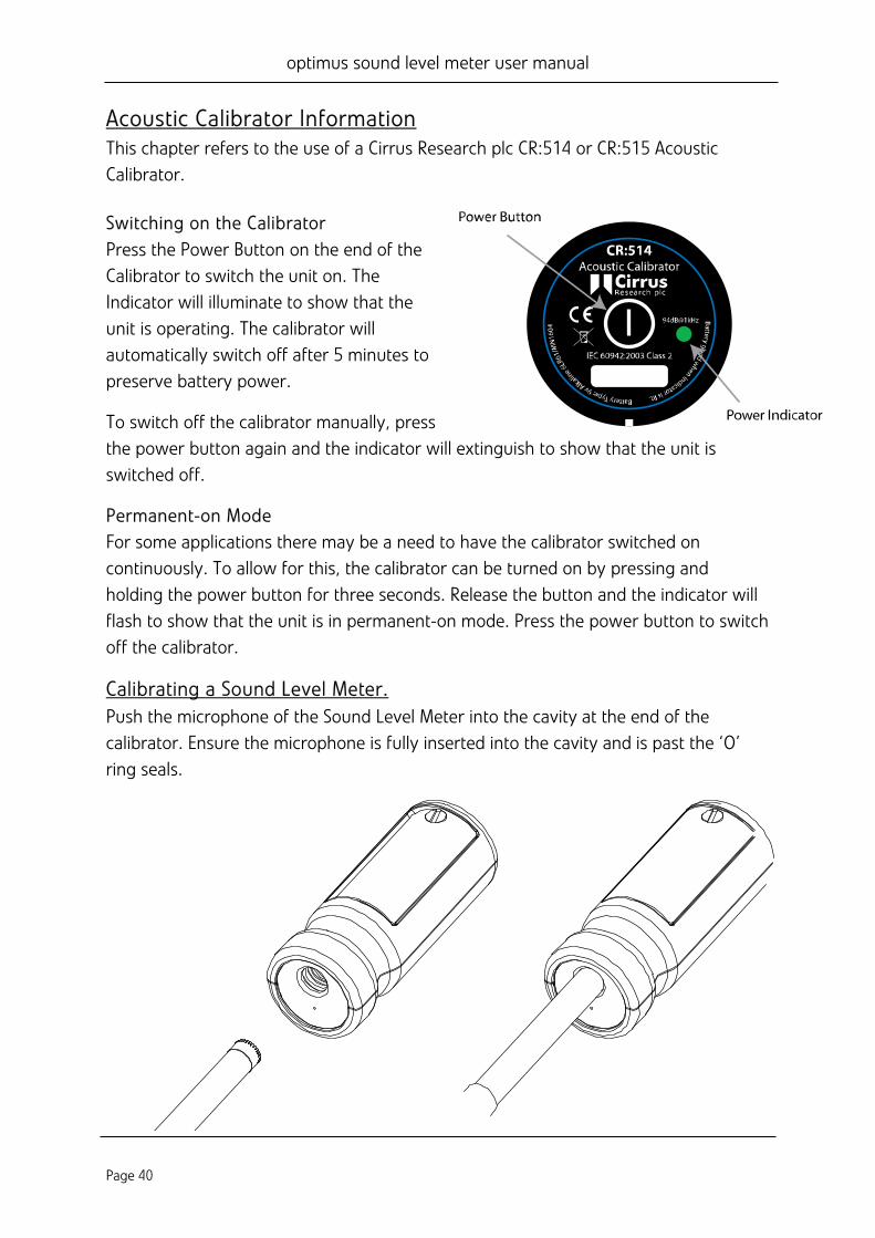
Acoustic Calibrator Information This chapter refers to the use of a Cirrus Research plc CR:514 or CR:515 Acoustic Calibrator.
Switching on the Calibrator Press the Power Button on the end of the Calibrator to switch the unit on. The Indicator will illuminate to show that the unit is operating. The calibrator will automatically switch off after 5 minutes to preserve battery power.
To switch off the calibrator manually, press the power button again and the indicator will extinguish to show that the unit is switched off.
Permanent-on Mode For some applications there may be a need to have the calibrator switched on continuously. To allow for this, the calibrator can be turned on by pressing and holding the power button for three seconds. Release the button and the indicator will flash to show that the unit is in permanent-on mode. Press the power button to switch off the calibrator.
Calibrating a Sound Level Meter. Push the microphone of the Sound Level Meter into the cavity at the end of the calibrator. Ensure the microphone is fully inserted into the cavity and is past the ‘O’ ring seals.
optimus sound level meter user manual
Page 41
The microphone should be parallel to the body of the calibrator. Also ensure that the small bleed-hole next to the microphone cavity is not blocked as this could cause damage to the microphone.
Your optimus sound level meter will automatically make adjustments for the level produced by the acoustic calibrator and the microphone type fitted to the instrument.
Background Noise In order for the calibrator to operate as intended, the ambient acoustic noise level should be no greater than 80dBA.
Stabilisation In order for the sound pressure level and frequency to stabilise after switching the calibrator on when coupled to a microphone, a period of at least 3 seconds should be allowed before performing a calibration.
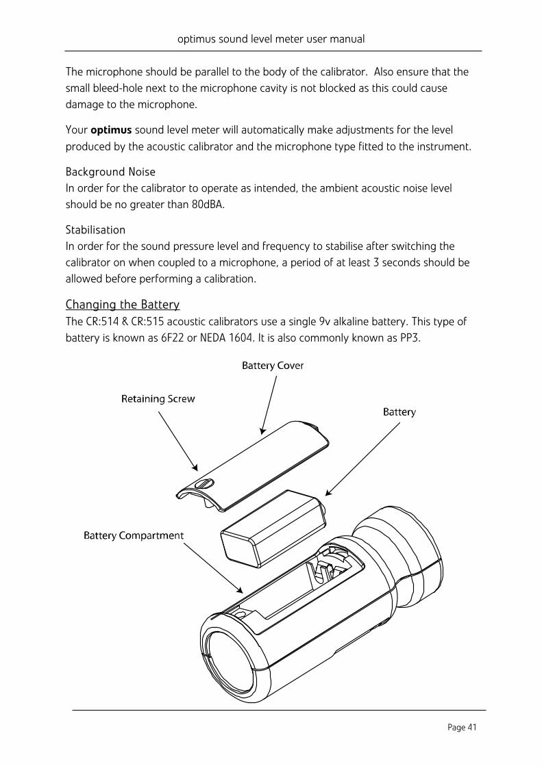
Changing the Battery The CR:514 & CR:515 acoustic calibrators use a single 9v alkaline battery. This type of battery is known as 6F22 or NEDA 1604. It is also commonly known as PP3.
optimus sound level meter user manual
Page 42
1. Unscrew the screw holding the battery cover on, using a coin or the keyring provided
2. The battery, type 6F22 (PP3) can now be eased out of its holder and replaced. The battery should be eased out terminal side first by pushing against the spring at the other end.
Ensure that the battery is inserted with the correct polarity with the negative terminal at the contact with the larger cut out.
Battery type The battery should be an alkaline battery, not an ordinary dry cell. The battery is 9 volts when new and will operate the calibrator down to 6.4 volts.
When the battery voltage is below 6.6 volts but above 6.4 volts, the power LED will flash to indicate that the battery voltage is low. When the battery voltage is below 6.4 volts the calibrator will not turn on.
A discharged battery may allow switch-on but will soon drop in voltage and indicate low battery or switch off.
Specifications Frequency 1kHz ± 1% Sound Level 94dB re 20μPa Standardisation CR:514 - IEC 60942:2003 Class 2 CR:515 - IEC 60942:2003 Class 1 Distortion Less than 2% Operating Humidity 25 to 90% Relative Humidity Operating Static Pressure 65 kPa to 108kPa Operating Temperature -10oC to +70oC Storing Temperature -20oC to +70oC Effective Volume 6.19 cm3 ± 0.2 cm3
Cavity Diameter 0.525 inch Battery 1 x 9v 6F22 (Neda 1604) Battery Life Approx 15 Hours Continuous Use Battery Voltage 9v Nominal (10v Maximum, 6.4v Minimum) Weight with Battery 185g Dimensions 135mm x Ø48mm
Technical Information The normal mode of operation of the calibrator is with the unit switched on.
optimus sound level meter user manual
Page 43
When the LED indicates the unit is switched on this produces the greatest radio frequency emissions.
The calibrator continues to function after exposure to contact discharges up to 4kV and air discharges up to 8kV, for both positive and negative voltages relative to earth ground. The calibrator conforms to IEC 60942:2003 for a modulated root-mean-square electromagnetic field strength of 10 V/m.
The maximum susceptibility to power and radio frequency fields is with the cavity facing away from the emitter with the battery compartment facing the table, the antenna polarisation horizontal and the calibrator switched on.
Free Field Correction When calibrating a microphone which is to be used for free field measurements, a small correction may be necessary to compensate for the difference between the microphone’s free field response at ‘zero degrees’ or ‘head-on’ incidence and the pressure level generated by the calibrator.
The correction is typically -0.3dB for ½ inch microphones (making the effective calibration level 93.7dB).
Calibration corrections are listed below for the Cirrus Research plc ½” Capsules and three microphone capsules commonly used in Calibration Laboratories:
Microphone Correction Values
Microphone Type Calibration Correction Effective Calibration Level MK:202 -0.3dB 93.7 dB MK:215 -0.3dB 93.7 dB MK:226 -0.3dB 93.7 dB MK:224 -0.3dB 93.7 dB B&K 4134 0dB 94.0 dB B&K 4180 0dB 94.0 dB B&K 4192 0dB 94.0 dB
Example
An example of the procedure used to calculate the value for an MK:224 microphone is shown below :
Level = 94.0dB + Microphone Correction Level = 94.0dB + ( -0.3dB) Level = 93.7dB
optimus sound level meter user manual
Page 44
CE Certificate of Conformity
Cirrus Research plc Hunmanby UK
Manufacturer: Cirrus Research plc Acoustic House, Bridlington Road Hunmanby, North Yorkshire, YO14 0PH United Kingdom Telephone +44 1723 891655
Equipment Description The following equipment manufactured after 1st January 2012: CR:151 Sound Level Meter (A & B Versions) CR:152 Sound Level Meter (A & B Versions) CR:161 Sound Level Meter (A, B, C & D Versions) CR:162 Sound Level Meter (A, B, C & D Versions) CR:171 Sound Level Meter (0, A, B & C Versions) CR:172 Sound Level Meter (0, A, B & C Versions) CR:19x Sound Level Meter (All versions) CR:514 Acoustic Calibrator CR:515 Acoustic Calibrator
Along with their standard accessories
According to EMC Directives 89/336/EEC and 93/98/EEC meet the following standards Sound Level Meters IEC 61672-1:2002, IEC 61672-2:2003 Acoustic Calibrators IEC 60942:2003
Except where modified by EN 61000-6-1:2007 & EN 61000-6-1:2007 EMC : Generic emission standard for residential, commercial and light industrial environments.
EN 61000-6-1 (2001) EMC : Generic immunity standard for residential, commercial and light industrial environments.
S. O Rourke Director Dated 1st January 2012
optimus sound level meter user manual
Page 45
Warranty 1. This document is a summary of the full warranty document and explains the Cirrus Research plc
warranty in ordinary English; not in legal or complex terms. 2. The warranty covers any acoustic instrument such as a sound level meter, acoustic calibrator, real
time acoustic analyser or personal sound exposure meter (dosemeter) manufactured by Cirrus Research plc after 1st September 2011.
3. The warranty covers all faults on the instrument resulting from manufacturing defects for the period defined in paragraph (5) below, including minor accidental damage except to the microphone.
4. The warranty excludes damage to the instrument(s) caused by the use of any accessories or components not specified or recommended by Cirrus Research plc.
5. The period of the warranty is 2 (two) years or 104 weeks from the date of purchase as a new instrument from Cirrus Research plc or their formally approved distributors OR 130 weeks from the date the instrument passed its final manufacturing inspection at Cirrus Research plc - whichever is the shorter.
6. Any rechargeable battery only has the battery manufacturer’s one year warranty however there will be a reduced charge for replacing rechargeable batteries during the annual “Routine Verification” process. (Commonly referred to as “Annual Recalibration”)
7. No warranty is offered for used equipment unless a special arrangement is made and a written confirmation of the warranty is given by Cirrus Research plc.
8. On completion of the routine verification by Cirrus Research plc, the instrument will automatically be given an additional free one year warranty.
9. There will be a charge for this routine verification and the price is published in the Service Price List.
10. The customer is responsible for all shipping, duty and other charges relating to the routine servicing and calibration of the instruments.
11. Where the instrument is deemed to be faulty due to manufacturing defects, Cirrus Research plc will cover the shipping, duty and other charges relating to the repair of the instrument. Cirrus Research plc reserves the right to decline an instrument under the warranty where there is clear evidence of damage or where no fault is found. In these cases, the customer will be liable for any shipping, duties or charges.
12. It follows that should the instrument be routinely verified by Cirrus Research plc every year, the warranty is effectively continuous to a maximum of 15 (fifteen) years from the date of purchase.
13. Cirrus Research endeavours to ensure stocks of instrument components for the full fifteen year period but do not guarantee to do so as certain components do become obsolete or discontinued.
14. If a sub-component becomes obsolete and stocks are depleted then Cirrus Research will endeavour to facilitate a repair but will not offer the same length guarantee.
15. In the event of any dispute on the terms of the warranty Cirrus Research plc will accept pendulum arbitration by the United Kingdom Institute of Acoustics Ltd.
16. The warranty does not in any way reduce any legal right of the buyer or user of the sound level meter; it is in addition to all legal rights determined by the European Union.
17. Cirrus Research plc reserves the right to amend or update these terms and conditions without prior notice.
optimus sound level meter user manual
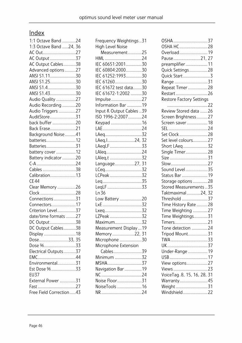
Page 46
Index 1:1 Octave Band ...........24 1:3 Octave Band .....24, 36 AC Out...........................27 AC Output .....................37 AC Output Cables ..........38 Advanced options .........27 ANSI S1.11.....................30 ANSI S1.25.....................30 ANSI S1.4.......................30 ANSI S1.43.....................30 Audio Quality ................27 Audio Recording ...........20 Audio Triggers ..............27 AuditStore .....................31 back buffer ...................20 Back Erase .....................21 Background Noise .........41 batteries ........................12 Batteries ........................31 battery cover ................12 Battery indicator ...........20 C-A ................................24 Cables ...........................38 Calibration .....................13 CE 44 Clear Memory ...............26 Clock .............................28 Connections ..................31 Connectors....................17 Criterion Level ...............37 date/time formats ........27 DC Output .....................38 DC Output Cables ..........38 Display ..........................18 Dose ........................33, 35 Dose % ..........................33 Electrical Outputs ..........37 EMC ...............................44 Environmental ...............31 Est Dose % ....................33 EU 37 External Power .............31 Fast ...............................27 Free Field Correction .....43
Frequency Weightings .. 31 High Level Noise
Measurement ........... 25 HML .............................. 24 IEC 60651:2001 ............. 30 IEC 60804:2000 ............. 30 IEC 61252:1993 ............. 30 IEC 61260 ...................... 30 IEC 61672 test data ....... 30 IEC 61672-1:2002 ......... 30 Impulse ......................... 27 Information Bar ............ 19 Input & Output Cables .. 39 ISO 1996-2:2007 ........... 24 Keypad ......................... 16 LAE ................................ 24 LAeq.............................. 32 LAeq,I ...................... 24, 32 LAeqLF .......................... 33 LAIeq ............................. 24 LAIeq,t .......................... 32 Language ................ 27, 31 LCeq .............................. 32 LCPeak .......................... 32 Leq ................................ 35 LeqLF ............................ 33 Ln 36 Low Battery .................. 20 LxE ................................ 32 Lxeq .............................. 32 LZPeak .......................... 32 Maximum...................... 32 Measurement Display ... 19 Memory .................. 22, 31 Microphone .................. 30 Microphone Extension
Cables ....................... 39 Minimum ...................... 32 MSHA ............................ 37 Navigation Bar .............. 19 NC ................................. 24 Noise Floor .................... 31 NoiseTools .................... 16 NR ................................. 24
OSHA ............................ 37 OSHA HC ....................... 28 Overload ....................... 19 Pause ...................... 21, 27 preamplifier .................. 11 Quick Settings ............... 28 Quick Start ...................... 3 Range ........................... 31 Repeat Timer ................ 28 Restart .......................... 26 Restore Factory Settings
................................. 22 Review Stored data ...... 26 Screen Brightness ......... 27 Screen saver ................. 18 SEL ................................ 24 Set Clock ....................... 28 Set level colours............ 27 Short LAeq .................... 32 Single Timer .................. 28 Size ............................... 31 Slow .............................. 27 Sound Level .................. 35 Status Bar ..................... 19 Storage options ............ 28 Stored Measurements .. 35 Taktmaximal ........... 24, 32 Threshold ..................... 37 Time History Rate ......... 28 Time Weighting ............ 27 Time Weightings ........... 31 Timers........................... 21 Tone detection ............. 24 Tripod Mount ................ 31 TWA .............................. 33 UK ................................. 37 Under-Range ................ 19 USB ............................... 17 View options ................. 27 Views ............................ 23 VoiceTag . 8, 15, 16, 28, 31 Warranty ....................... 45 Weight .......................... 31 Windshield .................... 22
optimus sound level meter user manual
Page 47
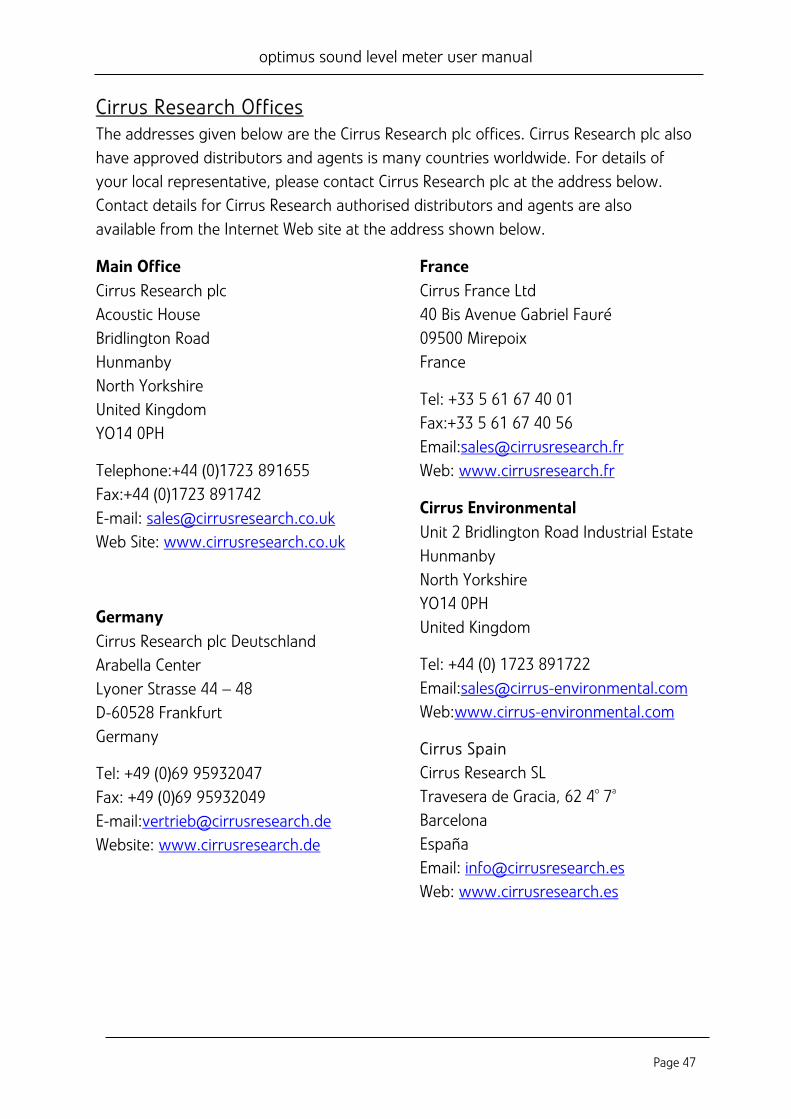
Cirrus Research Offices The addresses given below are the Cirrus Research plc offices. Cirrus Research plc also have approved distributors and agents is many countries worldwide. For details of your local representative, please contact Cirrus Research plc at the address below. Contact details for Cirrus Research authorised distributors and agents are also available from the Internet Web site at the address shown below.
Main Office Cirrus Research plc Acoustic House Bridlington Road Hunmanby North Yorkshire United Kingdom YO14 0PH
Telephone:+44 (0)1723 891655 Fax:+44 (0)1723 891742 E-mail: [email protected] Web Site: www.cirrusresearch.co.uk
Germany Cirrus Research plc Deutschland Arabella Center Lyoner Strasse 44 – 48 D-60528 Frankfurt Germany
Tel: +49 (0)69 95932047 Fax: +49 (0)69 95932049 E-mail:[email protected] Website: www.cirrusresearch.de
France Cirrus France Ltd 40 Bis Avenue Gabriel Fauré 09500 Mirepoix France
Tel: +33 5 61 67 40 01 Fax:+33 5 61 67 40 56 Email:[email protected] Web: www.cirrusresearch.fr
Cirrus Environmental Unit 2 Bridlington Road Industrial Estate Hunmanby North Yorkshire YO14 0PH United Kingdom
Tel: +44 (0) 1723 891722 Email:[email protected] Web:www.cirrus-environmental.com
Cirrus Spain Cirrus Research SL Travesera de Gracia, 62 4o 7a Barcelona España Email: [email protected] Web: www.cirrusresearch.es