Embed Size (px)
Citation preview

Eaton Electrical PREDICTIVE DIAGNOSTICS 5421 Feltl Road, Ste 190, Minnetonka, MN 55343 Phone (952) 912-1331 or -1358, Fax (952) 912-1355; Web-site: www.partial-discharge.com; e-mail: [email protected]
1
USER MANUAL
FOR TBS BUSHING SENSORS
© 2001, 2002, 2003, 2004 by EEPD
Version 6, June 2004
Eaton Electrical Predictive Diagnostics Installation Manual (V6.0) for TBS-2 sensors
2
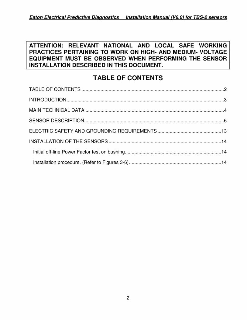
ATTENTION: RELEVANT NATIONAL AND LOCAL SAFE WORKING PRACTICES PERTAINING TO WORK ON HIGH- AND MEDIUM- VOLTAGE EQUIPMENT MUST BE OBSERVED WHEN PERFORMING THE SENSOR INSTALLATION DESCRIBED IN THIS DOCUMENT.
TABLE OF CONTENTS
TABLE OF CONTENTS .........................................................................................................2
INTRODUCTION....................................................................................................................3
MAIN TECHNICAL DATA ......................................................................................................4
SENSOR DESCRIPTION.......................................................................................................6
ELECTRIC SAFETY AND GROUNDING REQUIREMENTS...............................................13
INSTALLATION OF THE SENSORS ...................................................................................14
Initial off-line Power Factor test on bushing.......................................................................14
Installation procedure. (Refer to Figures 3-6)....................................................................14
Eaton Electrical Predictive Diagnostics Installation Manual (V6.0) for TBS-2 sensors
3
INTRODUCTION
This Manual is designed for qualified personnel involved in the on-site installation of TBS bushing sensors and commissioning of transformer insulation monitoring or measuring systems.
The state-of-the art TBS series bushing sensors are designated for installation on capacitor (potential) taps of high-voltage AC oil-filled bushings. The sensor output contains two superimposed signals, one being proportional to the power frequency current flowing through bushing insulation, the second being proportional to impulses arising from partial discharges (PD) in the insulation of the bushing and apparatus on which it is mounted (transformer, shunt reactor, circuit breaker).
The sensors of TBS-A type fit type A bushing test tap with thread 2.25” produced in accordance with ANSI-IEEE Std 57.19.01-1991. The sensor TBS-A-500 serves the bushings with rated voltages 70-500 kV. The sensor TBS-A-800 serves the bushings with rated voltages 735-800 kV. They look the same but have different sensor capacitance.
The sensors TBS-1.25, TBS-0.75 and TBS-M16 are designated for bushings with rated voltage below 70 kV having taps not covered by the standard. The thread of 1.25” is used particularly by Lapp; thread 0.75”- by GE and ABB, the metric thread M16x1.5 mm- by Trench. Old Ohio Brass bushing has 3/8-18 NPSC tap thread. TBS-OB-.625 serves old Ohio Brass bushings.
The coax cable from the sensor should be terminated in terminating or connection box whose design depends on the monitoring/measuring system used. Particularly, if the customer uses EEPD systems it could be the connection box of InsulGardTM G2+ monitoring system or terminating box TB-4U (refer, please, to respective brochures and Manuals).
Eaton Electrical Predictive Diagnostics Installation Manual (V6.0) for TBS-2 sensors
4
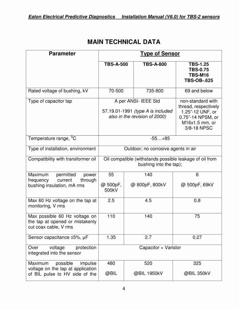
MAIN TECHNICAL DATA
Type of Sensor Parameter
TBS-A-500 TBS-A-800 TBS-1.25 TBS-0.75 TBS-M16
TBS-OB-.625
Rated voltage of bushing, kV 70-500 735-800 69 and below
Type of capacitor tap A per ANSI- IEEE Std
57.19.01-1991 (type A is included also in the revision of 2000)
non-standard with thread, respectively
1.25”-12 UNF, or 0.75”-14 NPSM, or
M16x1.5 mm, or 3/8-18 NPSC
Temperature range, 0C -55…+85
Type of installation, environment Outdoor; no corrosive agents in air
Compatibility with transformer oil Oil compatible (withstands possible leakage of oil from bushing into the tap);
Maximum permitted power frequency current through bushing insulation, mA rms
55
@ 500pF, 500kV
140
@ 800pF, 800kV
8
@ 500pF, 69kV
Max 60 Hz voltage on the tap at monitoring, V rms
2.5 4.5 0.8
Max possible 60 Hz voltage on the tap at opened or mistakenly cut coax cable, V rms
110 140 75
Sensor capacitance ±5%, µF 1.35 2.7 0.27
Over voltage protection integrated into the sensor
Capacitor + Varistor
Maximum possible impulse voltage on the tap at application of BIL pulse to HV side of the
480
@BIL
520
@BIL 1950kV
325
@BIL 350kV
Eaton Electrical Predictive Diagnostics Installation Manual (V6.0) for TBS-2 sensors
5
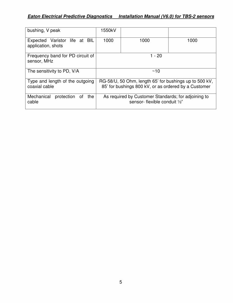
bushing, V peak 1550kV
Expected Varistor life at BIL application, shots
1000 1000 1000
Frequency band for PD circuit of sensor, MHz
1 - 20
The sensitivity to PD, V/A ~10
Type and length of the outgoing coaxial cable
RG-58/U, 50 Ohm, length 65’ for bushings up to 500 kV, 85’ for bushings 800 kV, or as ordered by a Customer
Mechanical protection of the cable
As required by Customer Standards; for adjoining to sensor- flexible conduit ½”

Eaton Electrical Predictive Diagnostics Installation Manual (V6.0) for TBS-2 sensors
6
SENSOR DESCRIPTION
The electrical circuit of all TBS series sensors is shown in Figure 1 TBS sensor schematic. and is protected by the US Patent #6,433,557. The electrode of the bushing capacitor tap is connected via a wire creating to a one - turn primary winding of the radio frequency current transformer (RFCT) to a varistor and capacitor connected in parallel and grounded on the body of sensor. The secondary winding of the RFCT consisting of several turns is connected to the capacitor and to the central wire of an outgoing coaxial cable. The sheath of the coaxial cable is grounded on the sensor body. As a result, the central wire of the coaxial cable carries two superimposed signals: one that is proportional to power frequency current flowing via bushing insulation, and the second in the form of radio frequency impulses accompanying PD occurrences. These signals can be easily separated in a measuring device.
Connector to thebushing tap
Coax. cable
RFCT
Var C2
Figure 1 TBS sensor schematic.
Bushing capacitance C1 and sensor capacitor C2 form a capacitance divider which limits power frequency voltage on the tap and on the output of the sensor to a level of 135 V rms or lower at rated voltages up to 500 kV, 140 V at 800 kV and 75 V or lower at voltages up to 69 kV. Although this level is safe for both the tap and sensor insulation we do not recommend allowing the coaxial cable to be unterminated. Capacitor C2 has different values for different rated voltages.
If cable isn’t connected to any device, short-circuit the end of the cable. If cable is connected to any measuring device it must provide appropriate burden impedance. When sensor is connected to a monitoring device InsulGard-G2+ its small input impedance limits the power frequency voltage on the tap electrode to a very low level (less 10V rms). When sensor cable is terminated in terminating box it must provide grounding of the cable between measurements. We recommend using terminating box TB-4U that provides this grounding.
Eaton Electrical Predictive Diagnostics Installation Manual (V6.0) for TBS-2 sensors
7
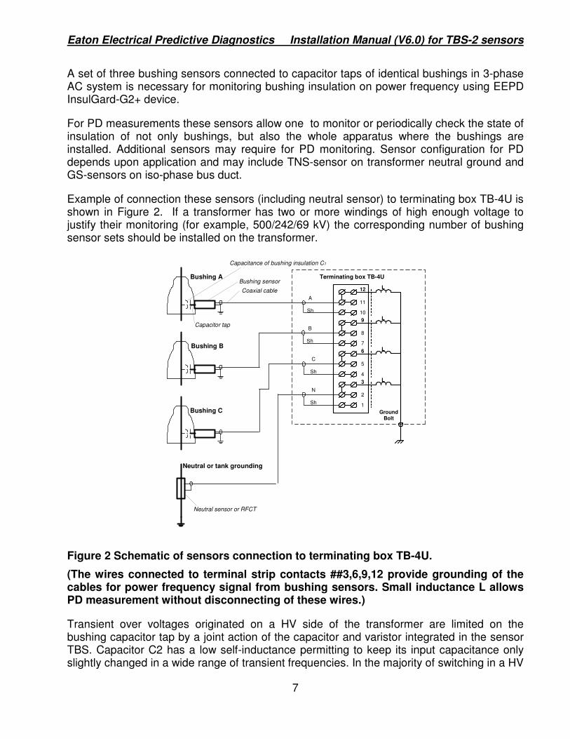
A set of three bushing sensors connected to capacitor taps of identical bushings in 3-phase AC system is necessary for monitoring bushing insulation on power frequency using EEPD InsulGard-G2+ device.
For PD measurements these sensors allow one to monitor or periodically check the state of insulation of not only bushings, but also the whole apparatus where the bushings are installed. Additional sensors may require for PD monitoring. Sensor configuration for PD depends upon application and may include TNS-sensor on transformer neutral ground and GS-sensors on iso-phase bus duct.
Example of connection these sensors (including neutral sensor) to terminating box TB-4U is shown in Figure 2. If a transformer has two or more windings of high enough voltage to justify their monitoring (for example, 500/242/69 kV) the corresponding number of bushing sensor sets should be installed on the transformer.
Coaxial cable
Bushing A
Bushing B
Bushing C
Neutral or tank grounding
Capacitance of bushing insulation C1
Bushing sensor
Capacitor tap
Neutral sensor or RFCT
12
11
109
8
76
5
43
2
1
L
GroundBolt
L
L
L
Terminating box TB-4U
A
Sh
B
Sh
C
Sh
N
Sh
Figure 2 Schematic of sensors connection to terminating box TB-4U.
(The wires connected to terminal strip contacts ##3,6,9,12 provide grounding of the cables for power frequency signal from bushing sensors. Small inductance L allows PD measurement without disconnecting of these wires.)
Transient over voltages originated on a HV side of the transformer are limited on the bushing capacitor tap by a joint action of the capacitor and varistor integrated in the sensor TBS. Capacitor C2 has a low self-inductance permitting to keep its input capacitance only slightly changed in a wide range of transient frequencies. In the majority of switching in a HV

Eaton Electrical Predictive Diagnostics Installation Manual (V6.0) for TBS-2 sensors
8
substation the switching overvoltages on the HV side of the transformer do not reach very high magnitudes, and the overvoltage on the tap may be limited by the capacitor action only. On average the number of such transients per year could be about 20-40 per a transformer. The heaviest conditions could be observed when the transformer is subjected to lightning overvoltage and its magnitude approaches the BIL of the transformer insulation. The insulation of the transformer is able to withstand a very limited number of such impacts- likely, not more than 10-20 per the whole transformer life. The varistor in the sensor is chosen to limit the overvoltage on the bushing tap in such cases to a safe value (550 V peak for 500 kV, 735 V for 800 kV and 325 V for 69 kV), and is capable to withstand 500-1000 BIL applications to the transformer.
The PD circuitry of the TBS sensor has the main frequency band of 1-20 MHz coordinated with PD measuring recording equipment characteristics, as well as its PD sensitivity. It is possible, particularly, to use an Eaton Electrical UPDA Analyzer or InsulGard� PD analyzer. In field conditions of power plants and 500 kV substations the analyzer was able to detect PD activity inside a transformer at the level of 30-50 pC. If sensors installed are used for PD measurements we recommend if possible to have identical length of coaxial cables for the whole set to make arriving of simultaneously originated pulses coinciding in time.
All elements of the TBS sensors can operate at temperatures –55 to + 850C, outdoors, without aggressive chemicals in the air. Pictures of different types of TBS sensors and sketches showing their positioning on capacitor taps are shown in Figures 3 - 7.
The sensors have similar design and consist of two parts: body and back lid as shown in the following figures. The body holds all protection components and has a thread to be screwed into a bushing flange. The components of electric circuitry are epoxy potted, so a sensor cannot be fully disassembled. The body has the neoprene rubber O-Ring that seals the interface between sensor and bushing flange. The 4” wire (red) with ring connector #6 passes both power frequency and high frequency signals to coaxial RG-58 cable molded into lid.
The lid is attached to the sensor body with three or four #8-32 screws. It has molded #6 thread terminal for signal wire connection. Neoprene rubber O-ring seals signal connection when the sensor is fully assembled. Protect internal sensor body surface from scratches and contamination to ensure appropriate sealing.
The lid has a standard fitting for standard 1/2” flexible conduit. Install the conduit to protect coaxial cable mechanically and from ultraviolet radiation
Eaton Electrical Predictive Diagnostics Installation Manual (V6.0) for TBS-2 sensors
9
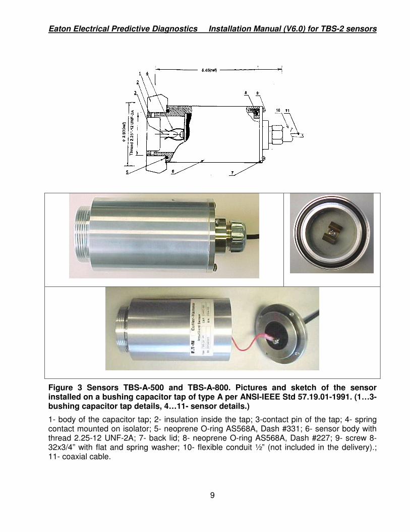
Figure 3 Sensors TBS-A-500 and TBS-A-800. Pictures and sketch of the sensor installed on a bushing capacitor tap of type A per ANSI-IEEE Std 57.19.01-1991. (1…3-bushing capacitor tap details, 4…11- sensor details.)
1- body of the capacitor tap; 2- insulation inside the tap; 3-contact pin of the tap; 4- spring contact mounted on isolator; 5- neoprene O-ring AS568A, Dash #331; 6- sensor body with thread 2.25-12 UNF-2A; 7- back lid; 8- neoprene O-ring AS568A, Dash #227; 9- screw 8-32x3/4” with flat and spring washer; 10- flexible conduit ½” (not included in the delivery).; 11- coaxial cable.
Eaton Electrical Predictive Diagnostics Installation Manual (V6.0) for TBS-2 sensors
10
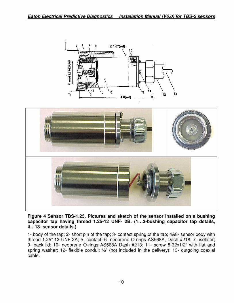
Figure 4 Sensor TBS-1.25. Pictures and sketch of the sensor installed on a bushing capacitor tap having thread 1.25-12 UNF- 2B. (1…3-bushing capacitor tap details, 4…13- sensor details.)
1- body of the tap; 2- short pin of the tap; 3- contact spring of the tap; 4&8- sensor body with thread 1.25”-12 UNF-2A; 5- contact; 6- neoprene O-rings AS568A, Dash #218; 7- isolator; 9- back lid; 10- neoprene O-rings AS568A Dash #213; 11- screw 8-32x1/2” with flat and spring washer; 12- flexible conduit ½” (not included in the delivery); 13- outgoing coaxial cable.

Eaton Electrical Predictive Diagnostics Installation Manual (V6.0) for TBS-2 sensors
11
Figure 5. Sensor TBS-0.75. Pictures and sketch of the sensor installed on a bushing capacitor tap having thread ¾”-14 NPSM. (1…3-bushing capacitor tap details, 4…12- sensor details.)
1- body of the tap; 2- pin of the tap; 3- contact spring of the tap; 4- contact; 5- neoprene O-Ring AS568A, Dash #318; 6- isolator; 7- sensor body with thread ¾”-14 NPSM; 8- neoprene O-rings AS568A Dash #213; 9- back lid; 10- screw 8-32x1/2” with flat and spring washer; 11- flexible conduit ½” (not included in the delivery); 12- outgoing coaxial cable.

Eaton Electrical Predictive Diagnostics Installation Manual (V6.0) for TBS-2 sensors
12
Figure 6. Sensor TBS-M16. Pictures and sketch of the sensor installed on a bushing capacitor tap having metric thread M16x1.5 mm. (1, 2,4- bushing capacitor tap details, 3, 5…12- sensor details.)
1- body of the tap; 2- manufacturer’s tap contact; 2a – spacer, 3- metric viton O-ring (ID 14 mm, WD 2.5 mm); 4- precision compression spring (OD 0.36”-9.14 mm, ID 7.01 mm, full LG at no load 20.6 mm, compressed LG 6.6 mm); 5&8- sensor body with metric thread M16x1.5 mm; 6- contact; 7- isolator; 9- neoprene O-rings AS568A Dash #213; 10- back lid, fastened by 3 screws 8-32x1/2” with flat and spring washers; 11- flexible conduit ½” (not included in the delivery); 12- outgoing coaxial cable.
2a
Eaton Electrical Predictive Diagnostics Installation Manual (V6.0) for TBS-2 sensors
13
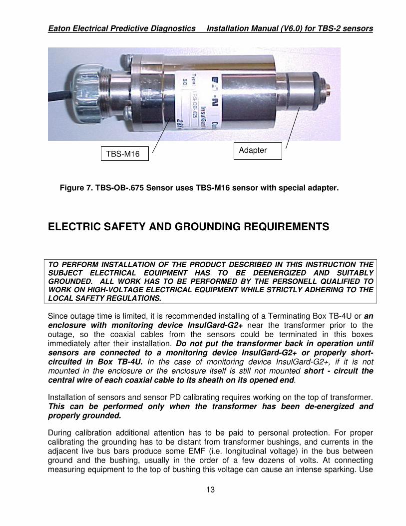
Figure 7. TBS-OB-.675 Sensor uses TBS-M16 sensor with special adapter.
ELECTRIC SAFETY AND GROUNDING REQUIREMENTS
TO PERFORM INSTALLATION OF THE PRODUCT DESCRIBED IN THIS INSTRUCTION THE SUBJECT ELECTRICAL EQUIPMENT HAS TO BE DEENERGIZED AND SUITABLY GROUNDED. ALL WORK HAS TO BE PERFORMED BY THE PERSONELL QUALIFIED TO WORK ON HIGH-VOLTAGE ELECTRICAL EQUIPMENT WHILE STRICTLY ADHERING TO THE LOCAL SAFETY REGULATIONS.
Since outage time is limited, it is recommended installing of a Terminating Box TB-4U or an enclosure with monitoring device InsulGard-G2+ near the transformer prior to the outage, so the coaxial cables from the sensors could be terminated in this boxes immediately after their installation. Do not put the transformer back in operation until sensors are connected to a monitoring device InsulGard-G2+ or properly short- circuited in Box TB-4U. In the case of monitoring device InsulGard-G2+, if it is not mounted in the enclosure or the enclosure itself is still not mounted short - circuit the central wire of each coaxial cable to its sheath on its opened end.
Installation of sensors and sensor PD calibrating requires working on the top of transformer. This can be performed only when the transformer has been de-energized and properly grounded.
During calibration additional attention has to be paid to personal protection. For proper calibrating the grounding has to be distant from transformer bushings, and currents in the adjacent live bus bars produce some EMF (i.e. longitudinal voltage) in the bus between ground and the bushing, usually in the order of a few dozens of volts. At connecting measuring equipment to the top of bushing this voltage can cause an intense sparking. Use
TBS-M16 Adapter

Eaton Electrical Predictive Diagnostics Installation Manual (V6.0) for TBS-2 sensors
14
protective gloves and be sure the equipment to be connected can withstand this longitudinal voltage.
When the power transformer is in operation the bushing taps are under a power frequency voltage. Until InsulGardTM G2+ device is connected to the sensors this voltage is very small, but if the cable end is opened the voltage can rise up to 95-140 V, depending on the rated voltage and capacitance C1 of the bushing. If in need to disconnect the monitoring device short-circuit cable ends taken out of InsulGardTM -G2+ inputs. At disconnecting the cable as well as at terminating earlier short-circuited cable take the appropriate safety measures applicable for working with live equipment under the voltage level of 150 V.
For safety purposes, the exteriors of bushing sensors are grounded at their locations, i.e. on the transformer tank, through their mechanical connections at the point of installation. The sheath of the output coaxial cable is grounded on the sensor inside its body. In the terminating box, if installed just near the transformer, the sheath may be left ungrounded.
INSTALLATION OF THE SENSORS
Initial off-line Power Factor test on bushing
After switching-off of the transformer and prior to installing bushing sensors on the bushing taps we recommend to make traditional power factor tests for both C1 and C2 bushing capacitances. This data will be used as information about the initial state of bushing insulation in further trending. You need not make these tests if they were provided on these bushings less than 6-8 months prior to sensor installation.
Installation procedure. (Refer to Figures 3-6)
After de-energizing a transformer and grounding it, unscrew the manufacturer’s grounding cap off the body of test tap and clean parts inside the tap. If working in snowy or rainy weather protect the tap, as well as the sensor from moisture penetration. Save the manufacturer’s cap for possible future re-installing.
Visually check that the sensor is in working order, fully assembled and all screws are tightened. Check the presence of a sealing O-Ring. For TBS-A sensors check that the distance between its spring contact (4), the fingers are about 0.25”.
At initial installation, when cable coiling is possible:
Coil the outgoing coaxial cable so you will be able to rotate it together with the sensor; this permits you to install fully assembled sensor.
Cautiously move the sensor to the threaded body of the tap, and screw it into the tap body. During screwing rotate the outgoing coaxial cable coiled together with the sensor. Stop screwing when deforming sealing O-ring provides a watertight joint. Uncoil the coaxial cable.

Eaton Electrical Predictive Diagnostics Installation Manual (V6.0) for TBS-2 sensors
15
Clearly mark all cables. Pull coaxial cable through conduit to location of terminating or InsulGardTMG2(+) enclosure. You may use solid conduit with at least 4 - 6’ flexible ½” portion next to the sensor location. Make sure that the flexible conduit allows to reach sensor body. Attach flexible conduit to the lid and tightly screw fitting nut on the lid. Check cable continuity after pulling it.
If cable coiling is impossible, for example, after cables were pulled in conduit:
Disassemble the sensor (if it is assembled) and disconnect the signal wire from its lid. Move the sensor body to the threaded body of the tap, and screw it cautiously into the bushing test tap body. Stop screwing when deforming O-ring provides a watertight joint. Normally with good thread this procedure does not require using a wrench.
Clearly mark all cables. Pull coaxial cable through conduit to location of terminating or InsulGardTMG2(+) enclosure. You may use solid conduit with at least 4-6’ flexible ½” portion next to the sensor location. Make sure that flexible conduit is allowed to reach sensor body. Check cable continuity after pulling it. Attach flexible conduit to the lid and tightly screw fitting nut on the lid.
Tightly connect signal wire from the sensor body to the lid terminal insert. Use spring washer provided with the sensor.
Cautiously attach lid to the sensor body with screws provided. Use both flat and spring washers for each screw. Make sure that sealing O-Ring gasket completely entered the body.
For both cases described above:
Using a multimeter measure the resistance between the cable sheath and the body of the sensor or the transformer tank; it has to be small (about 1 Ohm). Measure the resistance between the central wire of the coaxial cable and its sheath or the body of the sensor. It has to be high (of order of dozens MOhm). Measure the capacitance between the central wire and the sheath; it has to be about 1.35 µF for TBS-A-500, 2.7 µF for TBS-A-800 and 0.27µF for TBS-1.25, TBS-0.75 and TBS-M16.
Be sure that labels on the cable ends survived the routing. If cables are excessively long shorten them, preferably by the same length (including the cable from the neutral sensor or RFCT). Using spare labels put them on the shortened cables and connect the cables to the terminal strip in the terminating/ connection box.
Note for TBS-1.25 and TBS-0.75 sensors installation. (Refer to Figures 4 & 5)
When manufacturer’s grounding cap is removing be sure to keep in place the manufacturer’s contact spring (3) attached to the short pin (2) of the tap (Figures 4 & 5). Note that in some designs the spring (3) sits on a short bulge of pin (2), as is shown in Figure 4, and in others it can be attached to the pin (2) with a small screw, as is shown in Figure 5. The spring will protrude out of the tap for approximately 0.5”.
Eaton Electrical Predictive Diagnostics Installation Manual (V6.0) for TBS-2 sensors
16
During the sensor installation cautiously move the sensor to the threaded body of the tap, and looking into the gap catch the protruding end of the spring (3) inside the “cap” of the contact.
Note for TBS-M16 sensor installation. (Refer to Figure 6)
As a rule, when the manufacturer’s cap is unscrewed the tap contact (2) with spring (4) goes with it. In this case install a new tap contact and spring. At least one end of the spring is “closed”, i.e. smooth in the plane perpendicular to the spring axis. Carefully slide the spring onto the tap contact from that end until it stops on the contact shoulder. The spring will fit the tap contact well and stay in place when you free it. If connection of the spring to the tap contact is a bit loose take it off, draft it a bit and slide it again.
Looking into the gap between the tap contact with spring and the threaded end of the sensor body cautiously move the sensor body to the threaded body of the tap (1) along its axis, until the “gap” between them. When the body of the sensor touches the threaded hole in the tap body screw in the sensor body into the tap body until deforming O-ring (3) provides a watertight joint (the free end of the spring (4) has to be caught inside the “cap” of the contact (6). At tightening apply a moderate force as the thread is of a relatively small diameter and is short.
General remark about mechanical protection of the coaxial cables
As a rule, customer’s standards require mechanical protection of cables either with flexible conduits or with pipes. Although coaxial cables are weather-resistant for outdoor application, mechanical protection is desirable. The part of cable entering the sensor has to be protected with flexible conduit of ½” size. The steel pipe ½” cannot be used here as this will make the disconnecting the sensor very difficult. You need to use the flexible conduit at least on the short distance between the sensor and an outlet box on the top of the transformer where all cables may be jointly run further in the pipe. If you still do want to run cables without protection you may exclude the pipe or flexible conduit on the length between this outlet box and the connection/termination box of the monitoring system.
Calibrating sensors for partial discharges
PD calibration must be performed on a de-energized and grounded transformer. Avoid hazards produced by longitudinal EMF in the bus between bus grounding and the bushing.
Checking sensors under operating voltage
After installation and calibration of the sensors, the transformer may be energized. It is extremely important as the positive result confirms the proper continuity of circuit between the tap contact and sensor circuit and proper connection of the coaxial cable. The absence of good contact between the tap and sensor may make bushing monitoring impossible or even lead to bushing deterioration. The mismatching in the connection of coaxial cable grounds the bushing tap making monitoring impossible. The break in coaxial cable connection to sensor also makes monitoring impossible.

Eaton Electrical Predictive Diagnostics Installation Manual (V6.0) for TBS-2 sensors
17
The simplest way to check proper connecting is to measure with a multimeter or with the device itself (InsulGardTM G2) the power frequency current in each sensor output. That can be done in the terminating/connection box. The measured current has to correspond with reasonable correctness to a preliminary calculated estimate, and the sum of the currents in three-phase system of bushings measured by InsulGardTM G2 has to be small (<5%) in comparison with current flowing through the sensor of one bushing, even prior to full balancing.
If any of signs of improper connection, including an audible noise of sparking in the tap, is found the transformer has to be switched-off and grounded and suspected sensor has to be inspected, fixed and re-installed. If the mistake found cannot be fixed on-site, the manufacturer’s cap has to be re-installed on the tap instead of defective sensor, and EEPD should be notified.
Dismantling sensors and reinstallation.
You may wish to dismantle sensors in order, for example, to install them on another transformer or to perform a periodical off line power factor tests. That can be done only after de-energizing the transformer and grounding it.
Dismantling of the sensor should be done in the opposite of the installation order. In order to exclude the twisting of the coaxial cable do not unscrew the sensor from the tap until the lid is removed. After the lid is disconnected from the body of the sensor, disconnect the signal wire from the lid terminal, and then unscrew the sensor body from a tap.
Inspect and clean the surfaces of test tap. Carefully re-install the manufacturer’s cap if you are not planning re-installing the TBS sensor.
After re-installing of the sensor use the review the process described earlier - “Installation of the Sensors”. Before sensor reinstallation carefully visually check the state of all sealing O-Rings and springs affected during sensor dismantling. If it is necessary, replace deformed O-rings and springs.
Restore connections in the terminating/connection box if they were changed.
Then provide checking sensors under operating voltage as described in “Installation of the Sensors”.
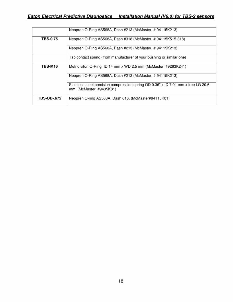
• We advise to obtain the following in advance as a spare parts:
Sensor Type Parts
Neopren O-Ring AS568A, Dash #331 (McMaster, #94115K515-331) TBS-A-500, TBS-A-800
Neopren O-Ring AS568A, Dash #227 (McMaster, #94115K227)
TBS-1.25 Neopren O-Ring AS568A, Dash #218 (McMaster, # 94115K218)
Eaton Electrical Predictive Diagnostics Installation Manual (V6.0) for TBS-2 sensors
18
Neopren O-Ring AS568A, Dash #213 (McMaster, # 94115K213)
Neopren O-Ring AS568A, Dash #318 (McMaster, # 94115K515-318) TBS-0.75
Neopren O-Ring AS568A, Dash #213 (McMaster, # 94115K213)
Tap contact spring (from manufacturer of your bushing or similar one)
Metric viton O-Ring, ID 14 mm x WD 2.5 mm (McMaster, #9263K241)
Neopren O-Ring AS568A, Dash #213 (McMaster, # 94115K213)
TBS-M16
Stainless steel precision compression spring OD 0.36” x ID 7.01 mm x free LG 20.6 mm. (McMaster, #9435K81)
TBS-OB-.675 Neopren O-ring AS568A, Dash 016, (McMaster#94115K01)