Embed Size (px)
Citation preview

202-10009-01
202-10009-01November 2003
NETGEAR, Inc.
4500 Great America Parkway
Santa Clara, CA
User Manual for the NETGEAR 7300 Series Layer 3 Managed Switch Software

ii
202-10009-01
© 2003 by NETGEAR, Inc., November 2003. FullManual All rights reserved.
Technical Support
Please register to obtain technical support. Please retain your proof of purchase and warranty information.
To register your product, get product support or obtain product information and product documentation, go to http://www.netgear.com. If you do not have access to the World Wide Web, you may register your product by filling out the registration card and mailing it to NETGEAR customer service.
You will find technical support information at: http://www.netgear.com/ through the customer service area. If you want to contact technical support by telephone, see the support information card for the correct telephone number for your country.
Trademarks
NETGEAR is a registered trademark of NETGEAR, INC. Windows is a registered trademark of Microsoft Corporation. Other brand and product names are trademarks or registered trademarks of their respective holders. Information is subject to change without notice. All rights reserved.
Statement of Conditions
In the interest of improving internal design, operational function, and/or reliability, NETGEAR reserves the right to make changes to the products described in this document without notice. NETGEAR does not assume any liability that may occur due to the use or application of the product(s) or circuit layout(s) described herein.
Regulatory Compliance Information
This device is restricted to indoor use due to reduce the potential for harmful interference to co-channel Mobile Satellite and Radar Systems.

202-10009-01
iii
Canadian Department of Communications Compliance Statement
This Class B Digital apparatus (NETGEAR 7300 Series Layer 3 Managed Switch) meets all the requirements of the Canadian Interference Causing Equipment Regulations. Cet appareil numerique del la classe B respect les exigences du Regalement sur le material broilleur du Canada.This device comples with Class B limits of Industry of Canada. Operation is subject to the following two conditions:1. This device may not cause harmful interference.2. This device must accept any interference received, including interference that may cause undesired operation.
EN 55 022 Declaration of Conformance
This is to certify that the NETGEAR 7300 Series Layer 3 Managed Switch is shielded against the generation of radio interference in accordance with the application of Council Directive 89/336/EEC, Article 4a. Conformity is declared by the application of EN 55 022 Class B (CISPR 22).

202-10009-01
iv

Contents v
202-10009-01
Contents
Chapter 1 About This Guide
Audience .........................................................................................................................1-1Why the Document was Created ....................................................................................1-1How to Use This Document ............................................................................................1-1Typographical Conventions ............................................................................................1-2Special Message Formats ..............................................................................................1-2Features of the HTML Version of this Manual ................................................................1-3How to Print this Manual .................................................................................................1-5
Chapter 2 Switch Management Overview
Scope .............................................................................................................................2-1Switch Management Overview .......................................................................................2-1
Chapter 3 Administration Console Telnet Interface
Set Up Your Switch Using Direct Console Access .........................................................3-1Chapter 4 Web-Based Management Interface
Web Based Management Overview ...............................................................................4-2How to Log In to the Managed Switch ............................................................................4-3Web-Based Management Utility Features ......................................................................4-5
Interactive Switch Image ..........................................................................................4-6Menus .............................................................................................................................4-6
Main Menus ..............................................................................................................4-7Secondary Menus ....................................................................................................4-8
Management ......................................................................................................4-8Switch ................................................................................................................4-8Routing ..............................................................................................................4-9Traffic Management ...........................................................................................4-9Smart Wizard .....................................................................................................4-9
System-Wide Popup Menus .....................................................................................4-9
202-10009-01
vi Contents
Port-Specific Popup Menus .................................................................................... 4-11Chapter 5 Command Line Interface Syntax
CLI Command Format ....................................................................................................5-1Command .................................................................................................................5-2Parameters ...............................................................................................................5-2Values ......................................................................................................................5-2Conventions .............................................................................................................5-3Annotations ..............................................................................................................5-4
Chapter 6 Quick Startup
Quick Starting the Switch ................................................................................................6-1System Info and System Setup ......................................................................................6-2
Quick Startup Software Version Information ............................................................6-2Quick Startup Physical Port Data .............................................................................6-3Quick Startup User Account Management ...............................................................6-4Quick Startup IP Address .........................................................................................6-4Quick Startup Uploading from Switch to Out-of-Band PC (Only XMODEM) ............6-6Quick Startup Downloading from Out-of-Band PC to Switch (Only XMODEM) .......6-6Quick Startup Downloading from TFTP Server ........................................................6-6Quick Startup Factory Defaults ................................................................................6-7
Configuration Examples .................................................................................................6-8Port Routing .............................................................................................................6-8
Routing Configuration ........................................................................................6-8RIP Configuration ..............................................................................................6-8OSPF Configuration ..........................................................................................6-9
VLAN Routing ..........................................................................................................6-9RIP Configuration ..............................................................................................6-9OSPF Configuration ........................................................................................6-10
VLAN Example .............................................................................................................6-12Solution 1 ...............................................................................................................6-13Solution 2 ...............................................................................................................6-13
Chapter 7 Switching Commands
System Information and Statistics Commands ...............................................................7-1
Contents vii
202-10009-01
show inventory .........................................................................................................7-1show sysinfo .............................................................................................................7-2config sysname ........................................................................................................7-2config syslocation .....................................................................................................7-3config syscontact ......................................................................................................7-3show arp switch ........................................................................................................7-3show forwardingdb table ..........................................................................................7-3show forwardingdb learned ......................................................................................7-4show stats port detailed ...........................................................................................7-4show stats port summary .........................................................................................7-9show stats switch detailed ......................................................................................7-10show stats switch summary ................................................................................... 7-11show eventlog ........................................................................................................7-12show msglog ..........................................................................................................7-12show traplog ...........................................................................................................7-12
Management Commands .............................................................................................7-13show network .........................................................................................................7-13config network macaddr .........................................................................................7-13config network mactype .........................................................................................7-14config network parms .............................................................................................7-14config network protocol ..........................................................................................7-14config network webmode .......................................................................................7-14config network javamode .......................................................................................7-15config prompt .........................................................................................................7-15show serial .............................................................................................................7-15config serial baudrate .............................................................................................7-16config serial timeout ...............................................................................................7-16show serviceport ....................................................................................................7-16config serviceport parms ........................................................................................7-16config serviceport protocol .....................................................................................7-16show snmpcommunity ............................................................................................7-17config snmpcommunity accessmode .....................................................................7-17config snmpcommunity create ...............................................................................7-18config snmpcommunity delete ................................................................................7-18config snmpcommunity ipaddr ...............................................................................7-18

202-10009-01
viii Contents
config snmpcommunity ipmask ..............................................................................7-18config snmpcommunity mode ................................................................................7-19show snmptrap .......................................................................................................7-19config snmptrap create ...........................................................................................7-19config snmptrap delete ...........................................................................................7-19config snmptrap ipaddr ...........................................................................................7-20config snmptrap mode ............................................................................................7-20show trapflags ........................................................................................................7-20config trapflags authentication ...............................................................................7-21config trapflags bcaststorm ....................................................................................7-21config trapflags linkmode .......................................................................................7-21config trapflags multiusers .....................................................................................7-21config trapflags stpmode ........................................................................................7-21show telnet .............................................................................................................7-22config telnet maxsessions ......................................................................................7-22config telnet mode ..................................................................................................7-22config telnet timeout ...............................................................................................7-22show forwardingdb agetime ...................................................................................7-23config forwardingdb agetime ..................................................................................7-23
Device Configuration Commands .................................................................................7-23show switchconfig ..................................................................................................7-24config switchconfig broadcast ................................................................................7-24config switchconfig flowcontrol ...............................................................................7-24show port ................................................................................................................7-24config port adminmode ...........................................................................................7-25config port flowcontrol ............................................................................................7-25config port linktrap ..................................................................................................7-26config port physicalmode .......................................................................................7-26config port lacpmode ..............................................................................................7-26config port autoneg ................................................................................................7-26show lag .................................................................................................................7-26config lag create .....................................................................................................7-27config lag addport ...................................................................................................7-27config lag deleteport ...............................................................................................7-27config lag adminmode ............................................................................................7-28

Contents ix
202-10009-01
config lag linktrap ...................................................................................................7-28config lag name ......................................................................................................7-28config lag deletelag ................................................................................................7-28config lag stpmode .................................................................................................7-28show vlan summary ...............................................................................................7-29show vlan detailed ..................................................................................................7-29config vlan create ...................................................................................................7-30config vlan delete ...................................................................................................7-30config vlan name ....................................................................................................7-30config vlan makestatic ............................................................................................7-31config vlan participation ..........................................................................................7-31config vlan port tagging ..........................................................................................7-31show vlan port ........................................................................................................7-32config vlan port pvid ...............................................................................................7-32config vlan port acceptframe ..................................................................................7-32config vlan port ingressfilter ...................................................................................7-33show protocol .........................................................................................................7-33config protocol create .............................................................................................7-33config protocol delete .............................................................................................7-33config protocol protocol add ...................................................................................7-34config protocol protocol remove .............................................................................7-34config protocol vlan add .........................................................................................7-34config protocol vlan remove ...................................................................................7-34config protocol interface add ..................................................................................7-35config protocol interface remove ............................................................................7-35show garp info ........................................................................................................7-35show garp interface ................................................................................................7-35config garp gmrp adminmode ................................................................................7-36config garp gmrp interface mode ...........................................................................7-36config garp gvrp adminmode ..................................................................................7-37config garp gvrp interface mode .............................................................................7-37config garp jointimer ...............................................................................................7-37config garp leavetimer ............................................................................................7-37config garp leavealltimer ........................................................................................7-38show igmpsnooping ...............................................................................................7-38

202-10009-01
x Contents
config igmpsnooping adminmode ..........................................................................7-39config igmpsnooping groupmembershipinterval .....................................................7-39config igmpsnooping maxresponse ........................................................................7-39config igmpsnooping mcrtrexpiretime ....................................................................7-39config igmpsnooping interface mode .....................................................................7-40show mfdb table .....................................................................................................7-40show mfdb gmrp .....................................................................................................7-40show mfdb igmpsnooping ......................................................................................7-41show mfdb staticfiltering .........................................................................................7-41show mfdb stats .....................................................................................................7-42show mirroring ........................................................................................................7-42config mirroring create ...........................................................................................7-42config mirroring delete ............................................................................................7-43config mirroring mode ............................................................................................7-43show macfilter ........................................................................................................7-43config macfilter create ............................................................................................7-43config macfilter remove ..........................................................................................7-44config macfilter addsrc ...........................................................................................7-44config macfilter delsrc ............................................................................................7-44config macfilter adddest .........................................................................................7-45config macfilter deldest ..........................................................................................7-45
Spanning Tree Commands ...........................................................................................7-45show spanningtree summary .................................................................................7-46config spanningtree adminmode ............................................................................7-46config spanningtree forceversion ...........................................................................7-47config spanningtree configuration name ................................................................7-47config spanningtree configuration revision .............................................................7-47show spanningtree port ..........................................................................................7-47config spanningtree port migrationcheck ...............................................................7-48config spanningtree port mode ...............................................................................7-48show spanningtree bridge ......................................................................................7-48config spanningtree bridge maxage .......................................................................7-49config spanningtree bridge hellotime .....................................................................7-49config spanningtree bridge forwarddelay ...............................................................7-49config spanningtree bridge priority .........................................................................7-49

Contents xi
202-10009-01
show spanningtree cst detailed ..............................................................................7-49show spanningtree cst port summary ....................................................................7-50show spanningtree cst port detailed .......................................................................7-51config spanningtree cst port pathcost ....................................................................7-51config spanningtree cst port priority .......................................................................7-52config spanningtree cst port edgeport ....................................................................7-52config spanningtree mst create ..............................................................................7-52config spanningtree mst delete ..............................................................................7-52config spanningtree mst vlan add ..........................................................................7-53config spanningtree mst vlan remove ....................................................................7-53config spanningtree mst priority .............................................................................7-53config spanningtree mst port pathcost ...................................................................7-53config spanningtree mst port priority ......................................................................7-54show spanningtree mst summary ..........................................................................7-54show spanningtree mst detailed .............................................................................7-54show spanningtree mst port summary ...................................................................7-55show spanningtree mst port detailed .....................................................................7-55show spanningtree vlan .........................................................................................7-55
User Account Management Commands .......................................................................7-56show users .............................................................................................................7-56config users add .....................................................................................................7-56config users passwd ...............................................................................................7-57config users delete .................................................................................................7-57config users snmpv3 authentication .......................................................................7-57config users snmpv3 encryption .............................................................................7-57config users snmpv3 accessmode .........................................................................7-58show loginsession ..................................................................................................7-58config loginsession close .......................................................................................7-58
Security Commands .....................................................................................................7-58config radius maxretransmit ...................................................................................7-59config radius timeout ..............................................................................................7-59config radius accounting mode ..............................................................................7-59config radius accounting server add ......................................................................7-60config radius accounting server port ......................................................................7-60config radius accounting server remove ................................................................7-60

202-10009-01
xii Contents
config radius accounting server secret ...................................................................7-60config radius server add .........................................................................................7-61config radius server port .........................................................................................7-61config radius server remove ...................................................................................7-61config radius server secret .....................................................................................7-61config radius server primary ...................................................................................7-62config radius server msgauth .................................................................................7-62show radius summary ............................................................................................7-62show radius server summary .................................................................................7-62show radius server stats ........................................................................................7-63show radius accounting summary ..........................................................................7-64show radius accounting stats .................................................................................7-64show radius stats ...................................................................................................7-65clear radius stats ....................................................................................................7-65config dot1x adminmode ........................................................................................7-65config dot1x port initialize .......................................................................................7-65config dot1x port reauthenticate .............................................................................7-65config dot1x port controldir .....................................................................................7-66config dot1x port controlmode ................................................................................7-66config dot1x port quietperiod ..................................................................................7-66config dot1x port transmitperiod .............................................................................7-67config dot1x port supptimeout ................................................................................7-67config dot1x port servertimeout ..............................................................................7-67config dot1x port maxrequests ...............................................................................7-67config dot1x port reauthperiod ...............................................................................7-67config dot1x port reauthenabled .............................................................................7-68show dot1x summary .............................................................................................7-68show dot1x port summary ......................................................................................7-68show dot1x port detailed ........................................................................................7-68show dot1x port stats .............................................................................................7-69clear dot1x port stats ..............................................................................................7-70config authentication login create ...........................................................................7-70config authentication login delete ...........................................................................7-71config authentication login set ................................................................................7-71config dot1x defaultlogin ........................................................................................7-72

Contents xiii
202-10009-01
config dot1x login ...................................................................................................7-72config dot1x port users add ....................................................................................7-72config dot1x port users remove ..............................................................................7-72config users defaultlogin ........................................................................................7-72config users login ...................................................................................................7-73show authentication login info ................................................................................7-73show authentication login users .............................................................................7-73show dot1x port users ............................................................................................7-73show users authentication ......................................................................................7-74
System Utilities .............................................................................................................7-74save config .............................................................................................................7-74logout .....................................................................................................................7-74transfer upload mode .............................................................................................7-74transfer upload serverip .........................................................................................7-75transfer upload path ...............................................................................................7-75transfer upload filename .........................................................................................7-76transfer upload datatype ........................................................................................7-76transfer upload start ...............................................................................................7-76transfer download mode .........................................................................................7-76transfer download serverip .....................................................................................7-77transfer download path ...........................................................................................7-77transfer download filename ....................................................................................7-77transfer download datatype ....................................................................................7-77transfer download start ...........................................................................................7-78clear transfer ..........................................................................................................7-78clear config .............................................................................................................7-78clear pass ...............................................................................................................7-78clear traplog ...........................................................................................................7-78clear vlan ................................................................................................................7-78clear lag ..................................................................................................................7-79clear stats port ........................................................................................................7-79clear stats switch ....................................................................................................7-79clear igmpsnooping ................................................................................................7-79reset system ...........................................................................................................7-79ping ........................................................................................................................7-80

202-10009-01
xiv Contents
Chapter 8 Routing Commands
VLAN Routing .................................................................................................................8-2show ip vlan .............................................................................................................8-2config ip vlan routing create .....................................................................................8-2config ip vlan routing delete .....................................................................................8-2
Router Commands .........................................................................................................8-2show router route table ............................................................................................8-2show router route bestroutes ...................................................................................8-3show router route entry ............................................................................................8-3show router route preferences .................................................................................8-4config router route create .........................................................................................8-4config router route delete .........................................................................................8-4config router route preference ..................................................................................8-4config router route default create .............................................................................8-5config router route default delete .............................................................................8-5
ARP Commands .............................................................................................................8-5show arp table ..........................................................................................................8-5config arp agetime ....................................................................................................8-6config arp cachesize ................................................................................................8-6config arp create ......................................................................................................8-6config arp delete .......................................................................................................8-6config arp resptime ...................................................................................................8-6config arp retries ......................................................................................................8-7
General IP Commands ...................................................................................................8-7show ip interface ......................................................................................................8-7config interface encaps ............................................................................................8-8config interface routing .............................................................................................8-8config ip interface mtu ..............................................................................................8-8config ip interface netdirbcast ..................................................................................8-8config ip interface create ..........................................................................................8-9config ip interface delete ..........................................................................................8-9show ip summary .....................................................................................................8-9config ip forwarding ................................................................................................8-10show ip stats ..........................................................................................................8-10

Contents xv
202-10009-01
config routing ..........................................................................................................8-10show router ip interface summary ..........................................................................8-10config router id ....................................................................................................... 8-11
RIP Commands ............................................................................................................ 8-11show router rip info ................................................................................................. 8-11show router rip interface detailed ........................................................................... 8-11show router rip interface summary .........................................................................8-12config router rip adminmode ..................................................................................8-12config router rip preference ....................................................................................8-12config router rip interface authtypekey ...................................................................8-13config router rip interface defaultmetric ..................................................................8-13config router rip interface mode .............................................................................8-13config router rip interface version receive ..............................................................8-13config router rip interface version send ..................................................................8-14
OSPF Commands ........................................................................................................8-14show router ospf info ..............................................................................................8-14config trapflags ospf ...............................................................................................8-15config router ospf adminmode ................................................................................8-15config router ospf asbr ...........................................................................................8-15config router ospf preference .................................................................................8-15show router ospf interface info ...............................................................................8-16show router ospf interface stats .............................................................................8-17show router ospf interface summary ......................................................................8-17config router ospf interface areaid ..........................................................................8-18config router ospf interface authtypekey ................................................................8-18config router ospf interface interval dead ...............................................................8-18config router ospf interface interval hello ...............................................................8-19config router ospf interface interval retransmit .......................................................8-19config router ospf interface iftransitdelay ...............................................................8-19config router ospf interface mode ...........................................................................8-19config router ospf interface priority .........................................................................8-20config router ospf interface cost .............................................................................8-20show router ospf area info ......................................................................................8-20show router ospf area range ..................................................................................8-21config router ospf area range create ......................................................................8-21

202-10009-01
xvi Contents
config router ospf area range delete ......................................................................8-21config router ospf area stub metric value ...............................................................8-22config router ospf area stub metric type .................................................................8-22config router ospf area stub summarylsa ...............................................................8-22config router ospf area stub create ........................................................................8-22config router ospf area stub delete .........................................................................8-23config router ospf area delete ................................................................................8-23show router ospf neighbor detailed ........................................................................8-23show router ospf neighbor table .............................................................................8-24show router ospf stub table ....................................................................................8-24show router ospf lsdb summary .............................................................................8-25show router ospf virtif detailed ...............................................................................8-25show router ospf virtif summary .............................................................................8-25config router ospf virtif create .................................................................................8-26config router ospf virtif delete .................................................................................8-26config router ospf virtif authtypekey .......................................................................8-26config router ospf virtif transdelay ..........................................................................8-26config router ospf virtif interval dead ......................................................................8-27config router ospf virtif interval hello .......................................................................8-27config router ospf virtif interval retransmit ..............................................................8-27config router ospf exoverflowinterval ......................................................................8-27config router ospf extlsdblimit .................................................................................8-28
Router Discovery Commands .......................................................................................8-28config router rtrdiscovery adminmode ....................................................................8-28config router rtrdiscovery maxinterval ....................................................................8-28config router rtrdiscovery mininterval .....................................................................8-28config router rtrdiscovery lifetime ...........................................................................8-29config router rtrdiscovery address ..........................................................................8-29config router rtrdiscovery preference .....................................................................8-29show router rtrdiscovery .........................................................................................8-29
VRRP Commands ........................................................................................................8-30show router vrrp info ..............................................................................................8-30config router vrrp adminmode ................................................................................8-30show router vrrp interface detailed .........................................................................8-30show router vrrp interface summary .......................................................................8-31

Contents xvii
202-10009-01
show router vrrp interface stats ..............................................................................8-31config router vrrp interface adminmode .................................................................8-32config router vrrp interface routerID .......................................................................8-32config router vrrp interface priority .........................................................................8-32config router vrrp interface ipaddress .....................................................................8-33config router vrrp interface preemptmode ..............................................................8-33config router vrrp interface advinterval ...................................................................8-33config router vrrp interface authdetails ...................................................................8-33config router vrrp removedetails .............................................................................8-34
BootP and DHCP Relay Commands ............................................................................8-34show router bootpdhcprelay ...................................................................................8-34config router bootpdhcprelay circuitidoptionmode ..................................................8-34config router bootpdhcprelay adminmode ..............................................................8-34config router bootpdhcprelay maxhopcount ...........................................................8-35config router bootpdhcprelay minwaittime ..............................................................8-35config router bootpdhcprelay serverip ....................................................................8-35
Chapter 9 Differentiated Services
General Commands .......................................................................................................9-3config diffserv adminmode .......................................................................................9-3
Class Commands ...........................................................................................................9-3config diffserv class create acl .................................................................................9-3config diffserv class create all ..................................................................................9-4config diffserv class create any ................................................................................9-4config diffserv class delete .......................................................................................9-5config diffserv class rename .....................................................................................9-5config diffserv class match cos ................................................................................9-5config diffserv class match dstip ..............................................................................9-6config diffserv class match dstl4port keyword ..........................................................9-6config diffserv class match dstl4port number ...........................................................9-6config diffserv class match dstl4port range ..............................................................9-7config diffserv class match dstmac ..........................................................................9-7config diffserv class match every .............................................................................9-8config diffserv class match ipdscp ............................................................................9-8config diffserv class match ipprecedence ................................................................9-9

202-10009-01
xviii Contents
config diffserv class match iptos ..............................................................................9-9config diffserv class match protocol keyword .........................................................9-10config diffserv class match protocol number ..........................................................9-10config diffserv class match refclass ........................................................................ 9-11config diffserv class match srcip ............................................................................9-12config diffserv class match srcl4port keyword ........................................................9-12config diffserv class match srcl4port number .........................................................9-12config diffserv class match srcl4port range ............................................................9-13config diffserv class match srcmac ........................................................................9-13config diffserv class match vlan .............................................................................9-14
Policy Commands .........................................................................................................9-14config diffserv policy create ....................................................................................9-15config diffserv policy delete ....................................................................................9-15config diffserv policy rename ..................................................................................9-15config diffserv policy class add ...............................................................................9-15config diffserv policy class remove .........................................................................9-16config diffserv policy bandwidth kbps .....................................................................9-16config diffserv policy bandwidth percent ................................................................9-16config diffserv policy expedite kbps ........................................................................9-17config diffserv policy expedite percent ...................................................................9-18config diffserv policy mark cos ...............................................................................9-18config diffserv policy mark ipdscp ..........................................................................9-19config diffserv policy mark ipprecedence ...............................................................9-19config diffserv policy police action conform drop ....................................................9-19config diffserv policy police action conform markdscp ...........................................9-20config diffserv policy police action conform markprec ............................................9-20config diffserv policy police action conform send ...................................................9-20config diffserv policy police action exceed drop .....................................................9-21config diffserv policy police action exceed markdscp .............................................9-21config diffserv policy police action exceed markprec .............................................9-22config diffserv policy police action exceed send ....................................................9-22config diffserv policy police action nonconform drop ..............................................9-22config diffserv policy police action nonconform markdscp .....................................9-23config diffserv policy police action nonconform markprec ......................................9-23config diffserv policy police action nonconform send .............................................9-23

Contents xix
202-10009-01
config diffserv policy police style simple .................................................................9-24config diffserv policy police style singlerate ...........................................................9-24config diffserv policy police style tworate ...............................................................9-25config diffserv policy randomdrop ..........................................................................9-26config diffserv policy shape average ......................................................................9-26config diffserv policy shape peak ...........................................................................9-27
Service Commands ......................................................................................................9-27config diffserv service add ......................................................................................9-28config diffserv service remove ................................................................................9-28
Show Commands .........................................................................................................9-29show diffserv class detailed ...................................................................................9-29show diffserv class summary .................................................................................9-30show diffserv info ...................................................................................................9-30show diffserv policy detailed ..................................................................................9-31show diffserv policy summary ................................................................................9-32show diffserv service info detailed .........................................................................9-33show diffserv service info summary .......................................................................9-33show diffserv service stats detailed ........................................................................9-34show diffserv service stats summary ......................................................................9-35
Chapter 10 ACL Commands
Show Commands .........................................................................................................10-1show acl summary .................................................................................................10-1show acl detailed ....................................................................................................10-1
Config Commands ........................................................................................................10-2config acl create .....................................................................................................10-2config acl delete .....................................................................................................10-2config acl rule create ..............................................................................................10-2config acl rule delete ..............................................................................................10-2config acl rule action ..............................................................................................10-3config acl rule match dstip ......................................................................................10-3config acl rule match dstl4port keyword .................................................................10-3config acl rule match dstl4port range .....................................................................10-4config acl rule match every ....................................................................................10-4config acl rule match ipdscp ...................................................................................10-4

202-10009-01
xx Contents
config acl rule match ipprecedence ........................................................................10-5config acl rule match iptos ......................................................................................10-5config acl rule match protocol keyword ..................................................................10-6config acl rule match protocol number ...................................................................10-6config acl rule match srcip ......................................................................................10-6config acl rule match srcl4port keyword .................................................................10-7config acl rule match srcl4port range .....................................................................10-7config acl interface add ..........................................................................................10-7config acl interface remove ....................................................................................10-8
Chapter 11 FSM7326P Power Over Ethernet Commands
Power Over Ethernet (POE) Commands ...................................................................... 11-2config poe port adminmode .................................................................................... 11-2config poe port priority ............................................................................................ 11-3config poe port limit ................................................................................................ 11-3config poe usagethreshold ..................................................................................... 11-3show poe port info .................................................................................................. 11-3
Class ................................................................................................................ 11-4Output .............................................................................................................. 11-4Limit ................................................................................................................. 11-4Status ............................................................................................................... 11-4
show poe info ......................................................................................................... 11-4Appendix A Cabling Guidelines
Fast Ethernet Cable Guidelines ....................................................................................12-1Category 5 Cable ..........................................................................................................12-2
Category 5 Cable Specifications ............................................................................12-2Twisted Pair Cables ...............................................................................................12-3Patch Panels and Cables .......................................................................................12-4
Using 1000BASE-T Gigabit Ethernet over Category 5 Cable ......................................12-5Cabling ...................................................................................................................12-5Near End Cross Talk (NEXT) .................................................................................12-6Patch Cables ..........................................................................................................12-6RJ-45 Plug and RJ-45 Connectors ........................................................................12-6Conclusion .............................................................................................................12-8

Contents xxi
202-10009-01
Appendix B Glossary
Numeric ........................................................................................................................13-1A ...................................................................................................................................13-2B ...................................................................................................................................13-3C ...................................................................................................................................13-4D ...................................................................................................................................13-5E ...................................................................................................................................13-6F ...................................................................................................................................13-7G ...................................................................................................................................13-8H ...................................................................................................................................13-9I .....................................................................................................................................13-9L .................................................................................................................................. 13-11M .................................................................................................................................13-12N .................................................................................................................................13-14O .................................................................................................................................13-14P .................................................................................................................................13-15Q .................................................................................................................................13-16R .................................................................................................................................13-17S .................................................................................................................................13-18T .................................................................................................................................13-19U .................................................................................................................................13-20V .................................................................................................................................13-20W ................................................................................................................................13-21X .................................................................................................................................13-22
Index

202-10009-01
xxii Contents

About This Guide 1-1
202-10009-01
Chapter 1 About This Guide
Thank you for purchasing the NETGEAR™ 7000 Series L3 Switch.
Audience
This reference manual assumes that the reader has basic-to-intermediate computer and Internet skills. However, basic computer network, Internet, and wireless technology tutorial information is provided in the Appendices.
This document describes configuration commands for the 7000 Series L3 Managed Switch software. The commands can be accessed from the CLI, telnet, and Web interfaces.
Why the Document was Created
This document was created primarily for system administrators configuring and operating a system using 7000 Series L3 Managed Switch software. It is intended to provide an understanding of the configuration options of 7000 Series L3 Managed Switch software.
It is assumed that the reader has an understanding of the relevant switch platforms. It is also assumed that the reader has a basic knowledge of Ethernet and networking concepts.
How to Use This Document
This document describes configuration commands for the 7000 Series L3 Managed Switch software. The commands can be accessed from the CLI, telnet, and Web interfaces.
• Chapter 6, “Quick Startup” details the procedure to quickly become acquainted with the 7000 Series L3 Managed Switch Software.
• Chapter 7, “Switching Commands” describes the Switching commands.
• Chapter 8, “Routing Commands” describes the Routing commands.

User Manual for the NETGEAR 7300 Series Layer 3 Managed Switch Software
1-2 About This Guide
202-10009-01
Note: Refer to the release notes for the 7000 Series L3 Managed Switch Software application level code. The release notes detail the platform specific functionality of the Switching, Routing, SNMP, Config, Management, and Bandwidth Provisioning packages.
Typographical Conventions
This guide uses the following typographical conventions:
Special Message Formats
This guide uses the following formats to highlight special messages:
This manual is written for the 7000 Series L3 Switch according to these specifications:
Table 1. Typographical conventions
italics Emphasis.
bold times roman User input.
[Enter] Named keys in text are shown enclosed in square brackets. The notation [Enter] is used for the Enter key and the Return key.
[Ctrl]+C Two or more keys that must be pressed simultaneously are shown in text linked with a plus (+) sign.
SMALL CAPS DOS file and directory names.
Note: This format is used to highlight information of importance or special interest.
Table 1-1. Manual Specifications
Product Version NETGEAR 7300 Series Layer 3 Managed Switch
Manual Publication Date November 2003
Note: Product updates are available on the NETGEAR, Inc. Web site at http://www.netgear.com/support/main.asp. Documentation updates are available on the NETGEAR, Inc. Web site at http://www.netgear.com/docs.
User Manual for the NETGEAR 7300 Series Layer 3 Managed Switch Software
About This Guide 1-3
202-10009-01
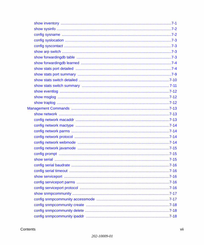
Features of the HTML Version of this ManualThe HTML version of this manual includes these features.
Figure Preface -2: HTML version of this manual
1. Left pane. Use the left pane to view the Contents, Index, Search, and Favorites tabs.
To view the HTML version of the manual, you must have a version 4 or later browser with JavaScript enabled.
2. Toolbar buttons. Use the toolbar buttons across the top to navigate, print pages, and more.
– The Show in Contents button locates the current topic in the Contents tab.
– Previous/Next buttons display the previous or next topic.
– The PDF button links to a PDF version of the full manual.
– The Print button prints the current topic. Using this button when a step-by-step procedure is displayed will send the entire procedure to your printer—you do not have to worry about specifying the correct range of pages.
3. Right pane. Use the right pane to view the contents of the manual. Also, each page of the manual includes a link at the top right which links to a PDF file containing just the currently selected chapter of the manual.
1 23

User Manual for the NETGEAR 7300 Series Layer 3 Managed Switch Software
1-4 About This Guide
202-10009-01
How to Print this ManualTo print this manual you man choose one of the following several options, according to your needs.• Printing a “How To” Sequence of Steps in the HTML View. Use the Print button on
the upper right of the toolbar to print the currently displayed topic. Using this button when a step-by-step procedure is displayed will send the entire procedure to your printer–you do not have to worry about specifying the correct range of pages.
• Printing a Chapter. Use the link at the top right of any page.
– Click “PDF of This Chapter” link at the top right of any page in the chapter you want to print. The PDF version of the chapter you were viewing opens in a browser window.
Note: Your computer must have the free Adobe Acrobat reader installed in order to view and print PDF files. The Acrobat reader is available on the Adobe Web site at http://www.adobe.com.
– Click the print icon in the upper left of the window.
Tip: If your printer supports printing two pages on a single sheet of paper, you can save paper and printer ink by selecting this feature.
• Printing the Full Manual. Use the PDF button in the toolbar at the top right of the browser window.
– Click the PDF button on the upper right of the toolbar. The PDF version of the chapter you were viewing opens in a browser window.
– Click the print icon in the upper left of the window.
Tip: If your printer supports printing two pages on a single sheet of paper, you can save paper and printer ink by selecting this feature.

Switch Management Overview 2-1
202-10009-01
Chapter 2Switch Management Overview
This chapter gives an overview of switch management, including the methods you can use to manage your NETGEAR NETGEAR 7300 Series Layer 3 Managed Switch.
• Management Access Overview
• SNMP Access
• Protocols
Scope
The 7000 Series L3 Managed Switch Software software has two purposes:
• Assist attached hardware in switching frames, based on Layer 2 or 3 information contained in the frames.
• Provide a complete switch management portfolio for the network administrator.
Switch Management Overview
Fast Ethernet (FEN) and Gigabit Ethernet (GEN) switching continues to evolve from high-end backbone applications to desktop switching applications. The price of the technology continues to decline, while performance and feature sets continue to improve. Devices that are capable of switching Layers 2, 3, and 4 are increasingly in demand. The NETGEAR 7300 Series Layer 3 Managed Switch provides a flexible solution to these ever-increasing needs.
The NETGEAR 7300 Series Layer 3 Managed Switch provides the network administrator with a set of comprehensive management functions for managing both the 7300 and the network. The network administrator has a choice of three easy-to-use management methods:
• Web-based
• VT100 interface
Note: The maximum number of configuration file command lines is 2000.

User Manual for the NETGEAR 7300 Series Layer 3 Managed Switch Software
2-2 Switch Management Overview
202-10009-01
• Simple Network Protocol Management (SNMP)
Each management method enables the network administrator to configure, manage, and control the managed switch locally or remotely using in-band or out-of-band mechanisms. Management is standards-based, with configuration parameters and a private MIB providing control for functions not completely specified in the MIBs.
Table 2-1. Comparing Switch Management Methods
Management Method Advantages DisadvantagesAdministration console
• Out-of-band access via direct cable connection means network bottlenecks, crashes, and downtime do not slow or prevent access
• No IP address or subnet needed• Menu or CLI based• HyperTerminal access to full functionality
(HyperTerminal are built into Microsoft Windows 95/98/NT/2000 operating systems)
• Secure – make sure the switch is installed in a secure area.
• Must be near switch or use dial-up connection
• Not convenient for remote users• Not graphical
Web browser or Telnet
• Can be accessed from any location via the switch’s IP address
• Ideal for configuring the switch remotely• Compatible with Internet Explorer and
Netscape Navigator Web browsers• Familiar browser interface• Graphical data available• Most visually appealing• Menu or CLI interfaces available
• Security can be compromised (hackers can attack if they know IP address)
• May encounter lag times on poor connections
• Displaying graphical objects over a browser interface may slow navigation
SNMP Agent • Communicates with switch functions at the Management Information Base (MIB) level
• Based on open standards
• Requires SNMP manager software• Least visually appealing of all three
methods• Limited amount of information
available• Some settings require calculations• Security can be compromised (hackers
need only know the community name)
Administration Console Telnet Interface 3-1
202-10009-01
Chapter 3 Administration Console Telnet Interface
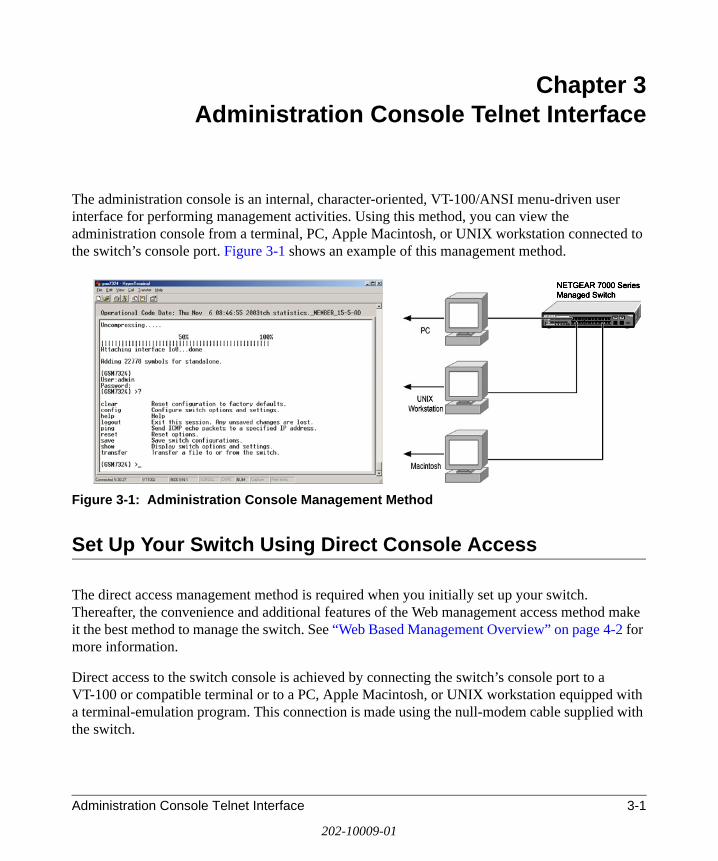
The administration console is an internal, character-oriented, VT-100/ANSI menu-driven user interface for performing management activities. Using this method, you can view the administration console from a terminal, PC, Apple Macintosh, or UNIX workstation connected to the switch’s console port. Figure 3-1 shows an example of this management method.
Figure 3-1: Administration Console Management Method
Set Up Your Switch Using Direct Console Access
The direct access management method is required when you initially set up your switch. Thereafter, the convenience and additional features of the Web management access method make it the best method to manage the switch. See “Web Based Management Overview” on page 4-2 for more information.
Direct access to the switch console is achieved by connecting the switch’s console port to a VT-100 or compatible terminal or to a PC, Apple Macintosh, or UNIX workstation equipped with a terminal-emulation program. This connection is made using the null-modem cable supplied with the switch.

User Manual for the NETGEAR 7300 Series Layer 3 Managed Switch Software
3-2 Administration Console Telnet Interface
202-10009-01
Examples of terminal-emulation programs include:
• HyperTerminal, which is included with Microsoft Windows operating systems
• ZTerm for the Apple Macintosh
• TIP for UNIX workstations
This example describes how to set up the connection using a HyperTerminal on a PC, but other systems follow similar steps.
1. Click the Windows Start button. Select Accessories and then Communications. HyperTerminal should be one of the options listed in this menu. Select HyperTerminal
2. The following screen will appear. Enter a name for this connection. In the example below, the name of the connection is FSM726. Click OK.
Figure 3-2: Connection Description
3. The following screen will appear. In the bottom, drop down box labeled Connect Using:, click the arrow and choose the COM port to which the switch will connect. In the example below, COM1 is the port selected. Click OK.
Figure 3-3: COM Port Selection

User Manual for the NETGEAR 7300 Series Layer 3 Managed Switch Software
Administration Console Telnet Interface 3-3
202-10009-01
4. When the following screen appears, make sure that the port setting are as follows:
Baud Rate: 9600Data Bits: 8Parity: NoneStop Bits: 1Flow Control: None
Figure 3-4: Connection Settings
5. Click OK.
The HyperTerminal window will open and you should be connected to the switch. If you do not get a welcome screen or a system menu, press the return key.
When attached to the User Interface via a Telnet Session, the following must be set in order to use the arrow keys: Under the terminal pull down menu, choose Properties and make sure the VT100 Arrows option is turned on.

User Manual for the NETGEAR 7300 Series Layer 3 Managed Switch Software
3-4 Administration Console Telnet Interface
202-10009-01

Web-Based Management Interface 4-1
202-10009-01
Chapter 4 Web-Based Management Interface
Your NETGEAR 7300 Series Layer 3 Managed Switch provides a built-in browser interface that lets you configure and manage it remotely using a standard Web browser such as Microsoft Internet Explorer 5.0 or later or Netscape Navigator 6.0 or later.
This interface also allows for system monitoring and management of the switch. The ‘help’ page covers many of the basic functions and features of the switch and it’s web interface.
When you configure the switch for the first time from the console, you can assign an IP address and subnet mask to the switch. Thereafter, you can access the switch’s Web interface directly using your Web browser by entering the switch’s IP address into the address bar. In this way, you can use your Web browser to manage the switch from a central location, just as if you were directly connected to the switch’s console port. Figure 4-1 shows this management method.
Figure 4-1: Web Management Method

User Manual for the NETGEAR 7300 Series Layer 3 Managed Switch Software
4-2 Web-Based Management Interface
202-10009-01
Web Based Management Overview
The menu options available are: System Management, Switch, Routing, Traffic Management, and Smart Wizard. There is a help menu in the top of right side of screen; you can click the ‘help’ or the question mark to read the help menu.
The help menu contains:
• Web-Based Management Introduction to the Web management features.
• Device Management Introduction of the basic icons and management of the device
• Interface Operations Describes Web browser requirements, and common commands
• Product Overview Describes supported SNMP and Web management features
• Summary of Features Feature List

User Manual for the NETGEAR 7300 Series Layer 3 Managed Switch Software
Web-Based Management Interface 4-3
202-10009-01
How to Log In to the Managed Switch
The NETGEAR 7300 Series Layer 3 Managed Switch can be configured remotely from Microsoft Internet Explorer browser version 5.0 or above, or Netscape Navigator web browser version 4.78 or above.
1. Determine the IP address of your managed switch.2. Open a Web browser such as Internet Explorer or Netscape Navigator. 3. Log in to the managed switch using whatever IP address the unit is currently configured with.
Use the default user name of admin and default of no password, or whatever LAN address and password you have set up.
.
Figure 4-2: 7300 IP address in browser address bar
A login window like the one shown below opens:
Figure 4-3: Login splash screen for the FSM7326P
Click the Login link.

User Manual for the NETGEAR 7300 Series Layer 3 Managed Switch Software
4-4 Web-Based Management Interface
202-10009-01
A user name and password dialog box opens like this one.
Figure 4-4: User name/password dialog box
4. Type the default user name of admin and default of no password, or whatever password you have set up.
Once you have entered your access point name, your Web browser should automatically find the 7000 Series L3 Switch and display the home page, as shown below.

User Manual for the NETGEAR 7300 Series Layer 3 Managed Switch Software
Web-Based Management Interface 4-5
202-10009-01
Web-Based Management Utility Features
Figure 4-5: System Information page
This welcome page displays system information, such as:
• System Description• System Name• System Location• System Contact• IP Address• System Object ID (OID)• System Up Time

User Manual for the NETGEAR 7300 Series Layer 3 Managed Switch Software
4-6 Web-Based Management Interface
202-10009-01
Interactive Switch Image
Figure 4-6: Interactive switch image
This dynamic image shows various real time conditions about the switch, including the status, fan operation, power, and the connectivity and traffic indication for each port. In addition, using the popup menus described below, you can directly access a wealth of information by right-clicking on a port and selecting a menu item from the popup-menu that displays.
Menus
The Web-based interface enables navigation through several menus. The main navigation menu is on the left of every page and contains the screens that let you access all the commands and statistics the switch provides.

User Manual for the NETGEAR 7300 Series Layer 3 Managed Switch Software
Web-Based Management Interface 4-7
202-10009-01
Figure 4-7: Menu navigation
Main Menus
• Management• Switch• Routing• Traffic Management• Smart Wizard

User Manual for the NETGEAR 7300 Series Layer 3 Managed Switch Software
4-8 Web-Based Management Interface
202-10009-01
Secondary Menus
The Secondary Menus under the Main Menu contain a host of options that you can use to configure your switch. The online help contains a detailed description of the features on each screen. You can click the ‘help’ or the question mark at the top right of each screen to view the help menu topics.
The Secondary Menus are detailed below, with cross-references to the sections in this manual that contain the corresponding command descriptions.
Management
• System — see “System Information and Statistics Commands” on page 7-1
• Utilities — see “System Utilities” on page 7-74
• Access — see the following sections:
• “BootP and DHCP Relay Commands” on page 8-34
• “General IP Commands” on page 8-7
• “Administration Console Telnet Interface” on page 3-1
• “Management Commands” on page 7-13
• Security — see “Security Commands” on page 7-58 and “User Account Management Commands” on page 7-56
• Port Access Control — “show dot1x port stats” on page 7-69
• RADIUS — see “show radius server stats” on page 7-63
• PoE — see “FSM7326P Power Over Ethernet Commands” on page 11-1
Switch
• Port — see “show port” on page 7-24
• MAC Addresses — see “System Information and Statistics Commands” on page 7-1
• Spanning Tree — see “Spanning Tree Commands” on page 7-45
• Link Aggregation — see “Device Configuration Commands” on page 7-23
• VLAN — see “show vlan summary” on page 7-29
• Mcast Fwding DB — see “show forwardingdb table” on page 7-3

User Manual for the NETGEAR 7300 Series Layer 3 Managed Switch Software
Web-Based Management Interface 4-9
202-10009-01
Routing
• VLAN Routing — see “VLAN Routing” on page 8-2
• Router — see “Router Commands” on page 8-2
• ARP — see “ARP Commands” on page 8-5
• IP — see “General IP Commands” on page 8-7
• RIP — see “RIP Commands” on page 8-11
• OSPF — see “OSPF Commands” on page 8-14
• Router Discovery — see “Router Discovery Commands” on page 8-28
• VRRP — see “VRRP Commands” on page 8-30
Traffic Management
• ACL — see “ACL Commands” on page 10-1
• Diffserv — see “Differentiated Services” on page 9-1
• Traffic Control — see “Management Commands” on page 7-13
Smart Wizard
• VLAN Routing Wizard — see “VLAN Routing” on page 8-2
• Diffserv Wizard — see “Differentiated Services” on page 9-1
System-Wide Popup Menus
The 7000 Series L3 Switch also provides several popup menus.
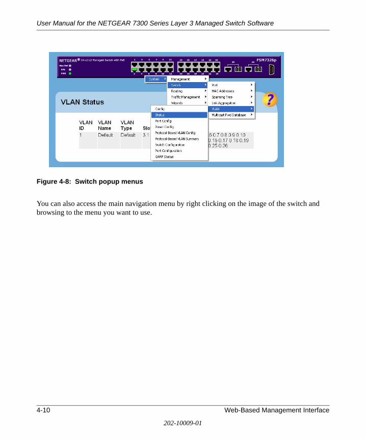
User Manual for the NETGEAR 7300 Series Layer 3 Managed Switch Software
4-10 Web-Based Management Interface
202-10009-01
Figure 4-8: Switch popup menus
You can also access the main navigation menu by right clicking on the image of the switch and browsing to the menu you want to use.

User Manual for the NETGEAR 7300 Series Layer 3 Managed Switch Software
Web-Based Management Interface 4-11
202-10009-01
Port-Specific Popup Menus
The 7000 Series L3 Switch also provides several popup menus for each port.
Figure 4-9: Switch popup menus
You can access a port-specific popup menu by right clicking on the port in the image of the switch and browsing to the menu you want to use.

User Manual for the NETGEAR 7300 Series Layer 3 Managed Switch Software
4-12 Web-Based Management Interface
202-10009-01

User Manual for the NETGEAR 7300 Series Layer 3 Managed Switch Software
Command Line Interface Syntax 5-1
202-10009-01
Chapter 5 Command Line Interface Syntax
The Command Line Interface (CLI) syntax, conventions and terminology are described in this section. Each CLI command is illustrated using the structure outlined below.
CLI Command Format
Commands are followed by values, parameters or both.
Example 1
config network parms <ipAddr> <netmask> [gateway]
• config network parms is the command name. • <ipAddr> <netmask> are the required values for the command.• [gateway] is the optional value for the command.
Example 2
config syslocation <location>
• config syslocation is the command name.• <location> is the required parameter for the command.
Example 3
config lag deleteport <logical slot.port> <slot.port|all>
• config lag deleteport is the command name. • <logical slot.port> <slot.port|all> are the required values for the
command.

User Manual for the NETGEAR 7300 Series Layer 3 Managed Switch Software
5-2 Command Line Interface Syntax
202-10009-01
Command
The text in bold, non-italic font must be typed exactly as shown.
Parameters
Parameters are order dependent.
The text in bold italics should be replaced with a name or number. To use spaces as part of a name parameter, enclose it in double quotes like this: "System Name with Spaces".
Parameters may be mandatory values, optional values, choices or a combination.
– <parameter>. The <> angle brackets indicate that a mandatory parameter must be entered in place of the brackets and text inside them.
– [parameter]. The [] square brackets indicate that an optional parameter must be entered in place of the brackets and text inside them.
– choice1|choice2. The | indicates that only one of the parameters should be entered.
Values
ipAddr This parameter is a valid IP address, made up of four decimal bytes ranging from 0 to 255. The default for all IP parameters consists of zeros and a one (that is, 0.0.0.1). The interface IP address of 0.0.0.0 is invalid. In some cases, the IP address can also be entered as a 32-bit number.
macAddr The MAC address format is six hexadecimal numbers separated by colons, for example, 0:6:29:32:81:40.
areaid Area IDs may be entered in dotted-decimal notation (for example, 0.0.0.1). An area ID of 0.0.0.0 is reserved for the backbone. Area IDs have the same form as IP addresses, but are distinct from IP addresses. The IP network number of the subnetted network may be used for the area ID.
routerid The value of <router id> must be entered in 4-digit dotted-deci-mal notation (for example, 0.0.0.1). A router ID of 0.0.0.0 is invalid.
slot.port This parameter denotes a valid slot number and a valid port num-ber. For example, 0.1 represents slot number 0 and port number 1.

User Manual for the NETGEAR 7300 Series Layer 3 Managed Switch Software
Command Line Interface Syntax 5-3
202-10009-01
The <slot.port> field is composed of a valid slot number and a valid port number separated by a period (.).
logical slot.port This parameter denotes a logical slot number and logical port number assigned. This is applicable in the case of a LAG. The operator can use the logical slot number and the logical port num-ber to configure the LAG.
Conventions
Network address are used to define a link to a remote host, workstation or network. Network addresses are shown using the following syntax:
Double quotation marks such as "System Name with Spaces" set off user-defined strings. If the operator wants to use spaces as part of a name parameter, it must be enclosed in double quotation marks.
Entering '@' in front of any command will allow the user to reference any root command from anywhere in the tree. For example, '>config router>@show arp table' will display the ARP table even though the command was not executed from the root level.
Command completion finishes spelling the command when enough letters of a command are typed to uniquely identify the command word. The command may be executed by typing <enter> (command abbreviation) or the command word may be completed by typing the <tab> or <space bar> (command completion).
The value 'Err' designates that the requested value was not internally accessible. This should never happen and indicates that there is a case in the software that is not handled correctly.
The value of '-----' designates that the value is unknown.
Table 1. Network Address Syntax
Address Type Format Range
ipAddr A.B.C.D 0.0.0.0 to 255.255.255.255(decimal)
macAddr YY:YY:YY:YY:YY:YY hexidecimal digit pairs

User Manual for the NETGEAR 7300 Series Layer 3 Managed Switch Software
5-4 Command Line Interface Syntax
202-10009-01
Annotations
The CLI allows the user to type single-line annotations at the command prompt for use when writing test or configuration scripts and for better readability. The exclamation point (‘!’) character flags the beginning of a comment. The comment flag character can begin a word anywhere on the command line and all input following this character is ignored. Any command line that begins with the character ‘!’ is recognized as a comment line and ignored by the parser.
Some examples are provided below:
! Script file for displaying the ip interface
! Display information about interfaces
show ip interface 0.1 !Displays the information about the first interface
! Display information about the next interface
show ip interface 0.2
! End of the script file

User Manual for the NETGEAR 7300 Series Layer 3 Managed Switch Software
Quick Startup 6-1
202-10009-01
Chapter 6 Quick Startup
The Command Line Interface (CLI) Quick Startup chapter details procedures to quickly become acquainted with the 7000 Series L3 Managed Switch Software.
This chapter contains the following Quick Startup examples:
• “System Info and System Setup” on page 6-2
• “Configuration Examples” on page 6-8
• “VLAN Example” on page 6-12
Quick Starting the Switch
1. Read the device Installation Guide for the connectivity procedure. In-band connectivity allows access to the 7000 Series L3 Managed Switch Software locally or from a remote workstation. The device must be configured with IP information (IP address, subnet mask, and default gateway).
2. Allow the device to load the software until the login prompt appears. The device initial state is called the default mode.
3. When the prompt asks for operator login, execute the following steps:
• Type the word admin in the login area. Since a number of the Quick Setup commands require administrator account rights, log in using an administrator account.
• Do not enter a password because there is no password in the default mode.• Press the enter key two times.

User Manual for the NETGEAR 7300 Series Layer 3 Managed Switch Software
6-2 Quick Startup
202-10009-01
System Info and System Setup
Quick Startup Software Version Information
Table 6-1. Quick Startup Software Version Information
Command Details
show inventory Allows the user to see the software version the device contains
Machine Model (The type and number of ports the device provides.)
For example: System Description ................................ netgearMachine Type ......………......................... 2402Burned In MAC Address ........................ 00:06:29:32:81:40Software Version ..................................... 1.0.0.9

User Manual for the NETGEAR 7300 Series Layer 3 Managed Switch Software
Quick Startup 6-3
202-10009-01
Quick Startup Physical Port Data
Table 6-2. Quick Startup Physical Port Data
Command Details
show port all Displays the Ports
Slot.Port - slot number.port number
Slot Options:
0 - the port is one of the physical ports1 - a link aggregation group (LAG). The port number field in this case refers to the LAG group ID.3 - a VLAN group. The port field starts with 1 as the first VLAN group created in the switch.
Port (when Slot value is 0):GSM7324 - ports 1-24 are gigabit copper ports, ports 21-24 can also be used as fiber portsGSM7312 - ports 1-12 can be used as either copper or fiber portsFSM7326 - ports 1-24 are fast Ethernet copper ports, ports 25-26 can be used as copper or fiber ports
Type - indicates if the port is a special type of port
STP State - displays the Spanning Tree status
Admin Mode - selects the Port Control Administration State
Physical Mode - selects the desired port speed and duplex mode
Physical Status - indicates the port speed and duplex mode
Link Status - indicates whether the link is up or down
Link Trap - determines whether or not to send a trap when link status changes
LACP Mode - displays whether LACP is enabled or disabled on this port.

User Manual for the NETGEAR 7300 Series Layer 3 Managed Switch Software
6-4 Quick Startup
202-10009-01
Quick Startup User Account Management
Quick Startup IP Address
To view the network parameters the operator can access the device by the following three methods.
• Simple Network Management Protocol - SNMP
• Telnet
• Web Browser
Note: Helpful Hint - do a save config after changing the network parameters so that the configurations are not lost.
Table 6-3. Quick Startup User Account Management
Command Details
show users Displays all of the users that are allowed to access the switch
Access Mode - Shows whether the user is able to change parameters on the switch (Read/Write) or is only able to view then (Read Only). As a factory default, admin has Read/Write access and guest has Read Only access. There can only be one Read/Write user and up to 5 Read Only users.
show loginsession Displays all of the login session information
config users passwd <user> Allows the user to set passwords or change passwords needed to log in.A prompt will appear after the command is entered requesting the users old password. In the absence of an old password leave the area blank. The operator must press enter to execute the command. The system then prompts the user for a new password then a prompt to confirm the new password. If the new password and the confirmed password match a message will be displayed
save config This will save passwords and all other changes to the device.If you do not save config, all configurations will be lost when a power cycle is performed on the switch or when the switch is reset
logout Logs the user out of the switch

User Manual for the NETGEAR 7300 Series Layer 3 Managed Switch Software
Quick Startup 6-5
202-10009-01
Table 6-4. Quick Startup IP Address
Command Details
show network Displays the Network Configurations
IP Address - IP Address of the interface Default IP is 0.0.0.0
Subnet Mask - IP Subnet Mask for the interfaceDefault is 0.0.0.0
Default Gateway - The default Gateway for this interfaceDefault value is 0.0.0.0
Burned in MAC Address - The Burned in MAC Address used for in-band connectivity
Locally Administered MAC Address - Can be configured to allow a locally administered MAC address
MAC Address Type - Specifies which MAC address should be used for in-band connectivity
Network Configurations Protocol Current - Indicates which network protocol is being used Default is DHCP
Java Mode - Specifies whether the switch should allow the Java applet to show the interactive switch graphic (see “Interactive Switch Image” on page 4-6)Default is enable
config network parms config network parms <ipAddr> <Mask> <gateway>
IP Address range from 0.0.0.0 to 255.255.255.255
Subnet Mask range from 0.0.0.0 to 255.255.255.255
Gateway Address range from 0.0.0.0 to 255.255.255.255

User Manual for the NETGEAR 7300 Series Layer 3 Managed Switch Software
6-6 Quick Startup
202-10009-01
Quick Startup Uploading from Switch to Out-of-Band PC (Only XMODEM)
Quick Startup Downloading from Out-of-Band PC to Switch (Only XMODEM)
Quick Startup Downloading from TFTP Server
Before starting a TFTP server download, the operator must complete the Quick Startup for the IP Address.
Table 6-5. Quick Startup Uploading from Switch to Out-of-Band PC (Only XMODEM)
Command Details
transfer upload mode xmodem Changes mode to xmodem which is initiated by the serial EIA 232 port
transfer upload datatype <config|errorlog|systemtrace|traplog>
The types are:config - configuration fileerrorlog - error logsystem trace - system tracetraplog - trap log
transfer upload start This starts the upload and also displays the mode of uploading and the type of upload it is and confirms the upload is taking place.For example: If the user is using HyperTerminal, the user must specify where the file is going to be received by the PC.
Table 6-6. Quick Startup Downloading from Out-of-Band PC to Switch (Only XMODEM)
Command Details
transfer download mode xmodem Makes the download mode to be xmodem
transfer download datatype <config/code> Sets the download datatype to be an image or config file.The default is a code file.
transfer download start For example: If the user is using HyperTerminal, the user must specify which file is to be sent to the switch.The Switch will restart automatically once the code has been downloaded.

User Manual for the NETGEAR 7300 Series Layer 3 Managed Switch Software
Quick Startup 6-7
202-10009-01
Quick Startup Factory Defaults
Table 6-7. Quick Startup Downloading from TFTP Server
Command Details
transfer download mode TFTP Makes the download mode to be TFTP
transfer download datatype <config/code> Sets the download datatype to be an image or config file.The default is a code file.
transfer download filename <name> The name can ONLY be an image file or a configuration file of the switch.
transfer download serverip <ipAddr> The IP Address is the source IP Address.
transfer download start Starts the TFTP download
Table 6-8. Quick Startup Factory Defaults
Command Details
clear config Enter yes when the prompt pops up to clear all the configurations made to the switch.
save config Enter yes when the prompt pops up that asks if you want to save the configurations made to the switch.
reset system OR Cold Boot the Switch
Enter yes when the prompt pops up that asks if you want to reset the system.This is the users choice either reset the switch or cold boot the switch, both work effectively.
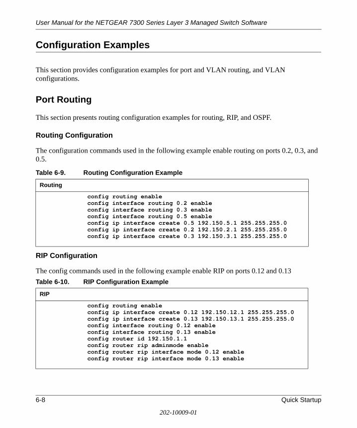
User Manual for the NETGEAR 7300 Series Layer 3 Managed Switch Software
6-8 Quick Startup
202-10009-01
Configuration Examples
This section provides configuration examples for port and VLAN routing, and VLAN configurations.
Port Routing
This section presents routing configuration examples for routing, RIP, and OSPF.
Routing Configuration
The configuration commands used in the following example enable routing on ports 0.2, 0.3, and 0.5..
RIP Configuration
The config commands used in the following example enable RIP on ports 0.12 and 0.13
Table 6-9. Routing Configuration Example
Routing
config routing enableconfig interface routing 0.2 enableconfig interface routing 0.3 enableconfig interface routing 0.5 enableconfig ip interface create 0.5 192.150.5.1 255.255.255.0config ip interface create 0.2 192.150.2.1 255.255.255.0config ip interface create 0.3 192.150.3.1 255.255.255.0
Table 6-10. RIP Configuration Example
RIP
config routing enableconfig ip interface create 0.12 192.150.12.1 255.255.255.0config ip interface create 0.13 192.150.13.1 255.255.255.0config interface routing 0.12 enableconfig interface routing 0.13 enableconfig router id 192.150.1.1config router rip adminmode enableconfig router rip interface mode 0.12 enableconfig router rip interface mode 0.13 enable

User Manual for the NETGEAR 7300 Series Layer 3 Managed Switch Software
Quick Startup 6-9
202-10009-01
OSPF Configuration
The config commands used in the following example enable OSPF on ports 0.1 and 0.2
VLAN Routing
This section provides examples of VLAN Routing for RIP and OSPF.
RIP Configuration
This example creates two router ports to run RIP 2.
Table 6-11. OSPF Configuration Example
OSPF
config routing enableconfig interface routing 0.1 enableconfig interface routing 0.2 enableconfig router id 192.150.2.1config router ospf interface areaid 0.1 0.0.0.0config router ospf interface areaid 0.2 0.0.0.0config ip interface create 0.1 192.150.2.1 255.255.255.0config ip interface create 0.2 192.150.3.1 255.255.255.0config router ospf adminmode enableconfig router ospf interface mode 0.1 enableconfig router ospf interface mode 0.2 enable

User Manual for the NETGEAR 7300 Series Layer 3 Managed Switch Software
6-10 Quick Startup
202-10009-01
OSPF Configuration
This example creates two router ports to run OSPF.
Table 6-12. VLAN Routing RIP Configuration
Step Example CLI Command
1. Create VLAN Disable console timeout.
config serial timeout 0
Create VLAN. SC box only supports VLAN routing, router port has to join VLAN.
config vlan create 10
config vlan create 20
Physical Port IDs are 0.1 and 0.2.
config vlan participation include 10 0.1
config vlan participation include 20 0.2
Create PVID for ports.
config vlan port pvid 10 0.1
config vlan port pvid 20 0.2
2. Create IP VLAN routing config ip vlan routing create 10
config ip vlan routing create 20
3. Enable the routing function for the virtual router
config routing enable
4. Config Router ID (virtual) config router id 192.168.111.50
5. Config IP interface (virtual)
Assign IP to router port 3.1 and 3.2.
config ip interface create 3.1 9.1.1.1 255.0.0.0
config ip interface create 3.2 192.168.111.1 255.255.255.0
6. Enable RIP protocol config router rip adminmode enable
config router rip interface mode 3.1 enable
config router rip interface mode 3.2 enable

User Manual for the NETGEAR 7300 Series Layer 3 Managed Switch Software
Quick Startup 6-11
202-10009-01
Table 6-13. VLAN Routing OSPF Configuration
Step Example CLI Command
1. Create VLAN Disable console timeout.
config serial timeout 0
Create VLAN. SC box only supports VLAN routing, router port has to join VLAN.
config vlan create 10
config vlan create 20
Physical Port IDs are 0.1 and 0.2.
config vlan participation include 10 0.1
config vlan participation include 20 0.2
Create PVID for ports.
config vlan port pvid 10 0.1
config vlan port pvid 20 0.2
2. Create IP VLAN routing config ip vlan routing create 10
config ip vlan routing create 20
3. Enable the routing function for the virtual router
config routing enable
4. Config Router ID (virtual) config router id 192.168.111.50
5. Config IP interface (virtual)
Assign IP to router port 3.1 and 3.2.
config ip interface create 3.1 9.1.1.1 255.0.0.0
config ip interface create 3.2 192.168.111.1 255.255.255.0
6. Enable OSPF protocol config router ospf adminmode enable
config router ospf interface mode 3.1 enable
config router ospf interface mode 3.2 enable

User Manual for the NETGEAR 7300 Series Layer 3 Managed Switch Software
6-12 Quick Startup
202-10009-01
VLAN Example
LAN switches can segment networks into logically defined virtual workgroups.This logical segmentation is commonly referred as a virtual LAN (VLAN). This logical segmentation of devices provides better LAN administration, security, and management of broadcast activity over the network. Virtual LANs have become an integral feature of switched LAN solutions.
The VLAN example below demonstrates a simple VLAN configuration with a 7000 Series L3 Managed Switch.
If a single port is a member of VLANs 2, 3 and 4, the port expects to see traffic tagged with either VLAN 2,3 or 4.
The PVID (Port Virtual Identification) could be something entirely different, for example '12' and things would still work fine, just so incoming traffic was tagged.
Example:
• Project A = (VLAN2, ports 1,2)• Project B = (VLAN3, ports 3,4)• Project C = (VLAN4, ports 5,6)• Project P = (VLAN 9, port 7)Table 6-14. Creating the VLANs
VLAN Command
create VLAN 2 config vlan create 2config vlan participation include 2 0.1config vlan participation include 2 0.2
create VLAN 3 config vlan create 3config vlan participation include 3 0.3config vlan participation include 3 0.4
create VLAN 4 config vlan create 4config vlan participation include 4 0.5config vlan participation include 4 0.6
create VLAN 9 config vlan create 9config vlan participation include 9 0.1config vlan participation include 9 0.2config vlan participation include 9 0.3config vlan participation include 9 0.4config vlan participation include 9 0.5config vlan participation include 9 0.6config vlan participation include 9 0.7

User Manual for the NETGEAR 7300 Series Layer 3 Managed Switch Software
Quick Startup 6-13
202-10009-01
Solution 1
All traffic entering the ports is tagged traffic. Since the traffic is tagged, the PVID configuration for each port is not a concern. The network card configuration is as follows:
• Devices on Project A should tag all traffic with 'VLAN 2'• Devices on Project B should tag all traffic with 'VLAN 3'• Devices on Project C should tag all traffic with 'VLAN 4'• Devices on Project P should tag all traffic with 'VLAN 9'
Solution 2
The network card configuration for devices on Project A, B and C should be set to NOT tag traffic.
To take care of these untagged frames configure the following:
• config vlan ports pvid 2 0.1• config vlan ports pvid 2 0.2• config vlan ports pvid 3 0.3• config vlan ports pvid 3 0.4• config vlan ports pvid 4 0.5• config vlan ports pvid 4 0.6

User Manual for the NETGEAR 7300 Series Layer 3 Managed Switch Software
6-14 Quick Startup
202-10009-01

User Manual for the NETGEAR 7300 Series Layer 3 Managed Switch Software
Switching Commands 7-1
202-10009-01
Chapter 7 Switching Commands
This chapter provides detailed explanation of the Switching commands. The commands are divided into five functional groups:
• Show commands display switch settings, statistics, and other information.
• Config commands configure features and options of the switch. For every config command there is a show command that displays the config setting.
• Transfer commands transfer configuration and informational files to and from the switch.
• Save commands save the switch configuration.
• Clear commands clear some or all of the settings to factory defaults.
This chapter is organized by configuration type:
• “System Information and Statistics Commands” on page 7-1
• “Management Commands” on page 7-13
• “Device Configuration Commands” on page 7-23
• “Spanning Tree Commands” on page 7-45
• “User Account Management Commands” on page 7-56
• “Security Commands” on page 7-58
• “System Utilities” on page 7-74
System Information and Statistics Commands
These commands display and configure system information and statistics.
show inventory
This command displays inventory information for the switch.Format show inventory

User Manual for the NETGEAR 7300 Series Layer 3 Managed Switch Software
7-2 Switching Commands
202-10009-01
Switch Description Text used to identify the product name of this switch.Machine Type Specifies the machine model as defined by the Vital Product Data.Machine Model Specifies the machine model as defined by the Vital Product Data.Serial Number The unique box serial number for this switch.FRU Number The field replaceable unit number.Part Number Manufacturing part number.Maintenance Level Indicates hardware changes that are significant to software.Manufacturer Manufacturer descriptor field.Burnedin MAC Address Universally assigned network address.Software Version The release.version.revision number of the code currently running on the
switch.Operating System The operating system currently running on the switch.Network Processing Element The type of the processor microcode. Additional Packages This displays the additional packages that are incorporated into this system,
such as FASTPATH BGP-4, or FASTPATH Multicast.
show sysinfo
This command displays switch information. Format show sysinfo Switch Description Text used to identify this switch.System Name Name used to identify the switch.System Location Text used to identify the location of the switch. May be up to 31 alpha-numeric
characters. The factory default is blank.System Contact Text used to identify a contact person for this switch. May be up to 31 alpha-
numeric characters. The factory default is blank.System ObjectID The base object ID for the switch’s enterprise MIB.System Up Time The time in days, hours and minutes since the last switch reboot.MIBs Supported A list of MIBs supported by this agent.
config sysname
This command sets the name assigned to the switch.The range for the name is from 1 to 31 alphanumeric characters.
Default BlankFormat config sysname <name>

User Manual for the NETGEAR 7300 Series Layer 3 Managed Switch Software
Switching Commands 7-3
202-10009-01
config syslocation
This command sets the physical location of the switch. The range for the name is from 1 to 31 alphanumeric characters.
Default BlankFormat config syslocation <location>
config syscontact
This command sets the organization responsible for the network. The range for the name is from 1 to 31 alphanumeric characters.
Default BlankFormat config syscontact <contact>
show arp switch
This command displays connectivity between the switch and other devices. The Address Resolution Protocol (ARP) cache identifies the MAC addresses of the IP stations communicating with the switch.
Format show arp switchMAC Address A unicast MAC address for which the switch has forwarding and/or filtering
information. The format is 6 two-digit hexadecimal numbers that are separated by colons, for example: 01:23:45:67:89:AB
IP Address The IP address assigned to each interface.Slot.Port This parameter denotes a valid slot number and a valid port number.
show forwardingdb table
This command displays the forwarding database entries. If the command is entered with no parameter, the entire table is displayed. This is the same as entering the optional all parameter. Alternatively, the administrator can enter a MAC Address to display the table entry for the requested MAC address and all entries following the requested MAC address.
Format show forwardingdb table [macaddr/all]Mac Address A unicast MAC address for which the switch has forwarding and or filtering
information. The format is 6 or 8 two-digit hexadecimal numbers that are separated by colons, for example, 01:23:45:67:89:AB. In an IVL system the MAC address will be displayed as 8 bytes. In an SVL system, the MAC address will be displayed as 6 bytes.

User Manual for the NETGEAR 7300 Series Layer 3 Managed Switch Software
7-4 Switching Commands
202-10009-01
Slot.Port The port which this address was learned.if Index This object indicates the ifIndex of the interface table entry associated with this
port.Status The status of this entry. The meanings of the values are: Static - The value of the corresponding instance was added by the system or a
user and cannot be relearned. Learned - The value of the corresponding instance was learned, and is being
used. Management - The value of the corresponding instance is also the value of an
existing instance of dot1d Static Address. Currently this is used when enabling VLANs for routing.
Self - The value of the corresponding instance is the system’s own MAC address.
GMRP Learned - The value of the corresponding instance was learned via GMRP.
Other - The value of the corresponding instance does not fall into one of the other categories.
show forwardingdb learned
This command displays the forwarding database entries for learned addresses. If the command is entered with no parameter, all learned addresses are displayed. This is the same as entering the optional all parameter. Alternatively, the administrator can enter a VLAN and MAC Address to display the table entry for the requested MAC address and all learned entries following the requested MAC address.
Format show forwardingdb learned[vlanplusmacaddr/all]Mac Address A unicast MAC address for which the switch has forwarding and or filtering
information. The format is 6 or 8 two-digit hexadecimal numbers that are separated by colons, for example, 01:23:45:67:89:AB. In an IVL system the MAC address will be displayed as 8 bytes. In an SVL system, the MAC address will be displayed as 6 bytes.
Slot.Port The port which this address was learned.if Index This object indicates the ifIndex of the interface table entry associated with this
port.Status The status of this entry. This value will always be Learned.
show stats port detailed
This command displays detailed statistics for a specific port.Format show stats port detailed <slot.port>Packets Received

User Manual for the NETGEAR 7300 Series Layer 3 Managed Switch Software
Switching Commands 7-5
202-10009-01
Octets Received - the total number of octets of data (including those in bad packets) received on the network (excluding framing bits but including FCS octets). This object can be used as a reasonable estimate of ethernet utilization. If greater precision is desired, the etherStatsPkts and etherStatsOctets objects should be sampled before and after a common interval. The result of this equation is the value Utilization which is the percent utilization of the ethernet segment on a scale of 0 to 100 percent. Packets Received < 64 Octets - the total number of packets (including bad packets) received that were < 64 octets in length (excluding framing bits but including FCS octets). Packets Received 64 Octets - the total number of packets (including bad packets) received that were 64 octets in length (excluding framing bits but including FCS octets). Packets Received 65-127 Octets - the total number of packets (including bad packets) received that were between 65 and 127 octets in length inclusive (excluding framing bits but including FCS octets). Packets Received 128-255 Octets - the total number of packets (including bad packets) received that were between 128 and 255 octets in length inclusive (excluding framing bits but including FCS octets). Packets Received 256-511 Octets - the total number of packets (including bad packets) received that were between 256 and 511 octets in length inclusive (excluding framing bits but including FCS octets). Packets Received 512-1023 Octets - the total number of packets (including bad packets) received that were between 512 and 1023 octets in length inclusive (excluding framing bits but including FCS octets). Packets Received 1024-1518 Octets - the total number of packets (including bad packets) received that were between 1024 and 1518 octets in length inclusive (excluding framing bits but including FCS octets). Packets Received 1519-1522 Octets - the total number of packets (including bad packets) received that were between 1519 and 1522 octets in length inclusive (excluding framing bits but including FCS octets). Packets Received > 1522 Octets - the total number of packets received that were longer than 1522 octets (excluding framing bits, but including FCS octets) and were otherwise well formed.
Packets Received Successfully Total - the total number of packets received that were without errors. Unicast Packets Received - the number of subnetwork-unicast packets delivered to a higher-layer protocol. Multicast Packets Received - the total number of good packets received that were directed to a multicast address. Note that this number does not include packets directed to the broadcast address. Broadcast Packets Received - the total number of good packets received that were directed to the broadcast address. Note that this does not include multicast packets.
Packets Received with MAC Errors

User Manual for the NETGEAR 7300 Series Layer 3 Managed Switch Software
7-6 Switching Commands
202-10009-01
Total - the total number of inbound packets that contained errors preventing them from being deliverable to a higher-layer protocol. Jabbers Received - the total number of packets received that were longer than 1518 octets (excluding framing bits, but including FCS octets), and had either a bad Frame Check Sequence (FCS) with an integral number of octets (FCS Error) or a bad FCS with a non-integral number of octets (Alignment Error). Note that this definition of jabber is different than the definition in IEEE-802.3 section 8.2.1.5 (10BASE5) and section 10.3.1.4 (10BASE2). These documents define jabber as the condition where any packet exceeds 20 ms. The allowed range to detect jabber is between 20 ms and 150 ms. Fragments/Undersize Received - the total number of packets received that were less than 64 octets in length (excluding framing bits but including FCS octets). Alignment Errors - the total number of packets received that had a length (excluding framing bits, but including FCS octets) of between 64 and 1518 octets, inclusive, but had a bad Frame Check Sequence (FCS) with a non-integral number of octets. Rx FCS Errors - the total number of packets received that had a length (excluding framing bits, but including FCS octets) of between 64 and 1518 octets, inclusive, but had a bad Frame Check Sequence (FCS) with an integral number of octets Overruns - the total number of frames discarded as this port was overloaded with incoming packets, and could not keep up with the inflow.
Received Packets not forwarded Total - a count of valid frames received which were discarded (i.e. filtered) by the forwarding process. Local Traffic Frames - the total number of frames dropped in the forwarding process because the destination address was located off of this port. 802.3x Pause Frames Received - a count of MAC Control frames received on this interface with an opcode indicating the PAUSE operation. This counter does not increment when the interface is operating in half-duplex mode. Unacceptable Frame Type - the number of frames discarded from this port due to being an unacceptable frame type. VLAN Membership Mismatch - the number of frames discarded on this port due to ingress filtering. VLAN Viable Discards - the number of frames discarded on this port when a lookup on a particular VLAN occurs while that entry in the VLAN table is being modified, or if the VLAN has not been configured. Multicast Tree Viable Discards - the number of frames discarded when a lookup in the multicast tree for a VLAN occurs while that tree is being modified. Reserved Address Discards - the number of frames discarded that are destined to an IEEE 802.1 reserved address and are not supported by the system. Broadcast Storm Recovery - the number of frames discarded that are destined for FF:FF:FF:FF:FF:FF when Broadcast Storm Recovery is enabled.

User Manual for the NETGEAR 7300 Series Layer 3 Managed Switch Software
Switching Commands 7-7
202-10009-01
CFI Discards - the number of frames discarded that have CFI bit set and the addresses in RIF are in non-canonical format. Upstream Threshold - the number of frames discarded due to lack of cell descriptors available for that packet's priority level.
Packets Transmitted Octets Total Bytes - the total number of octets of data (including those in bad packets) received on the network (excluding framing bits but including FCS octets). This object can be used as a reasonable estimate of ethernet utilization. If greater precision is desired, the etherStatsPkts and etherStatsOctets objects should be sampled before and after a common interval.Packets Transmitted 64 Octets - the total number of packets (including bad packets) received that were 64 octets in length (excluding framing bits but including FCS octets). Packets Transmitted 65-127 Octets - the total number of packets (including bad packets) received that were between 65 and 127 octets in length inclusive (excluding framing bits but including FCS octets). Packets Transmitted 128-255 Octets - the total number of packets (including bad packets) received that were between 128 and 255 octets in length inclusive (excluding framing bits but including FCS octets). Packets Transmitted 256-511 Octets - the total number of packets (including bad packets) received that were between 256 and 511 octets in length inclusive (excluding framing bits but including FCS octets). Packets Transmitted 512-1023 Octets - the total number of packets (including bad packets) received that were between 512 and 1023 octets in length inclusive (excluding framing bits but including FCS octets). Packets Transmitted 1024-1518 Octets - the total number of packets (including bad packets) received that were between 1024 and 1518 octets in length inclusive (excluding framing bits but including FCS octets). Packets Transmitted 1519-1522 Octets - the total number of packets (including bad packets) received that were between 1519 and 1522 octets in length inclusive (excluding framing bits but including FCS octets). Max Info - the maximum size of the Info (non-MAC) field that this port will receive or transmit.
Packets Transmitted Successfully Total - the number of frames that have been transmitted by this port to its
segment. Unicast Packets Transmitted - the total number of packets that higher-level protocols requested be transmitted to a subnetwork-unicast address, including those that were discarded or not sent. Multicast Packets Transmitted - the total number of packets that higher-level protocols requested be transmitted to a Multicast address, including those that were discarded or not sent. Broadcast Packets Transmitted - the total number of packets that higher-level protocols requested be transmitted to the Broadcast address, including those that were discarded or not sent.
Transmit Errors

User Manual for the NETGEAR 7300 Series Layer 3 Managed Switch Software
7-8 Switching Commands
202-10009-01
Total Errors - the sum of Single, Multiple, and Excessive Collisions. FCS Errors - the total number of packets transmitted that had a length (excluding framing bits, but including FCS octets) of between 64 and 1518 octets, inclusive, but had a bad Frame Check Sequence (FCS) with an integral number of octets Oversized - the total number of frames that exceeded the max permitted frame size. This counter has a max increment rate of 815 counts per sec. at 10 Mb/s. Underrun Errors - the total number of frames discarded because the transmit FIFO buffer became empty during frame transmission.
Transmit Discards Total Discards - the sum of single collision frames discarded, multiple collision
frames discarded, and excessive frames discarded. Single Collision Frames - a count of the number of successfully transmitted frames on a particular interface for which transmission is inhibited by exactly one collision. Multiple Collision Frames - a count of the number of successfully transmitted frames on a particular interface for which transmission is inhibited by more than one collision. Excessive Collisions - a count of frames for which transmission on a particular interface fails due to excessive collisions. Port Membership - the number of frames discarded on egress for this port due to egress filtering being enabled. VLAN Viable Discards - the number of frames discarded on this port when a lookup on a particular VLAN occurs while that entry in the VLAN table is being modified, or if the VLAN has not been configured.
Protocol Statistics BPDU's received - the count of BPDU's (Bridge Protocol Data Units) received
in the spanning tree layer. BPDU's Transmitted - the count of BPDU's (Bridge Protocol Data Units) transmitted from the spanning tree layer. 802.3x Pause Frames Received - a count of MAC Control frames received on this interface with an opcode indicating the PAUSE operation. This counter does not increment when the interface is operating in half-duplex mode. GVRP PDU's Received - the count of GVRP PDU's received in the GARP layer.GVRP PDU's Transmitted - the count of GVRP PDU's transmitted from the GARP layer. GVRP Failed Registrations - the number of times attempted GVRP registrations could not be completed. GMRP PDU's received - the count of GMRP PDU's received in the GARP layer. GMRP PDU's Transmitted - the count of GMRP PDU's transmitted from the GARP layer. GMRP Failed Registrations - the number of times attempted GMRP registrations could not be completed.

User Manual for the NETGEAR 7300 Series Layer 3 Managed Switch Software
Switching Commands 7-9
202-10009-01
STP BPDUs Transmitted - Spanning Tree Protocol Bridge Protocol Data Units sentSTP BPDUs Received - Spanning Tree Protocol Bridge Protocol Data Units receivedRST BPDUs Transmitted - Rapid Spanning Tree Protocol Bridge Protocol Data Units sentRSTP BPDUs Received - Rapid Spanning Tree Protocol Bridge Protocol Data Units receivedMSTP BPDUs Transmitted - Multiple Spanning Tree Protocol Bridge Protocol Data Units sentMSTP BPDUs Received - Multiple Spanning Tree Protocol Bridge Protocol Data Units received
Dot1x Statistics EAPOL Frames Received - the number of valid EAPOL frames of any type that have been received by this authenticator.EAPOL Frames Transmitted - the number of valid EAPOL frames of any type that have been transmitted by this authenticator.
Time Since Counters Last Cleared The elapsed time, in days, hours, minutes, and seconds since the statistics for
this port were last cleared.
show stats port summary
This command displays a summary of statistics for a specific port.Format show stats port summary <slot.port>Packets Received Without Error The total number of packets (including broadcast packets and multicast packets)
received by the processor. Packets Received With Error The number of inbound packets that contained errors preventing them from
being deliverable to a higher-layer protocol. Broadcast Packets Received The total number of packets received that were directed to the broadcast
address. Note that this does not include multicast packets. Packets Transmitted Without Error The total number of packets transmitted out of the interface. Transmit Packets Errors The number of outbound packets that could not be transmitted because of errors. Collisions Frames The best estimate of the total number of collisions on this Ethernet segment. Time Since Counters Last Cleared The elapsed time, in days, hours, minutes, and seconds since the statistics for
this port were last cleared.

User Manual for the NETGEAR 7300 Series Layer 3 Managed Switch Software
7-10 Switching Commands
202-10009-01
show stats switch detailed
This command displays detailed statistics for all CPU traffic.Format show stats switch detailed
Total Packets Received (Octets) - the total number of octets of data received by the processor (excluding framing bits but including FCS octets). Packets Received Without Error - the total number of packets (including broadcast packets and multicast packets) received by the processor. Unicast Packets Received - the number of subnetwork-unicast packets delivered to a higher-layer protocol. Multicast Packets Received - the total number of packets received that were directed to a multicast address. Note that this number does not include packets directed to the broadcast address. Broadcast Packets Received - the total number of packets received that were directed to the broadcast address. Note that this does not include multicast packets. Receive Packets Discarded - the number of inbound packets which were chosen to be discarded even though no errors had been detected to prevent their being deliverable to a higher-layer protocol. A possible reason for discarding a packet could be to free up buffer space. Octets Transmitted - the total number of octets transmitted out of the interface, including framing characters. Packets Transmitted without Errors - the total number of packets transmitted out of the interface. Unicast Packets Transmitted - the total number of packets that higher-level protocols requested be transmitted to a subnetwork-unicast address, including those that were discarded or not sent. Multicast Packets Transmitted - the total number of packets that higher-level protocols requested be transmitted to a Multicast address, including those that were discarded or not sent. Broadcast Packets Transmitted - the total number of packets that higher-level protocols requested be transmitted to the Broadcast address, including those that were discarded or not sent. Transmit Packets Discarded - the number of outbound packets which were chosen to be discarded even though no errors had been detected to prevent their being deliverable to a higher-layer protocol. A possible reason for discarding a packet could be to free up buffer space. Most Address Entries Ever Used - the highest number of Forwarding Database Address Table entries that have been learned by this switch since the most recent reboot. Address Entries in Use - the number of Learned and static entries in the Forwarding Database Address Table for this switch. Maximum VLAN Entries - the maximum number of Virtual LANs (VLANs) allowed on this switch.

User Manual for the NETGEAR 7300 Series Layer 3 Managed Switch Software
Switching Commands 7-11
202-10009-01
Most VLAN Entries Ever Used - the largest number of VLANs that have been active on this switch since the last reboot. Static VLAN Entries - the number of presently active VLAN entries on this switch that have been created statically. Dynamic VLAN Entries - the number of presently active VLAN entries on this switch that have been created by GVRP registration. VLAN Deletes - the number of VLANs on this switch that have been created and then deleted since the last reboot.
Time Since Counters Last Cleared The elapsed time, in days, hours, minutes, and seconds, since the statistics for
this switch were last cleared.
show stats switch summary
This command displays a count of all CPU traffic.Format show stats switch summaryPackets Received Without Error The total number of packets (including broadcast packets and multicast packets)
received by the processor. Broadcast Packets Received The total number of packets received that were directed to the broadcast
address. Note that this does not include multicast packets. Packets Received With Error The number of inbound packets that contained errors preventing them from
being deliverable to a higher-layer protocol. Packets Transmitted Without Error The total number of packets transmitted out of the interface. Broadcast Packets Transmitted The total number of packets that higher-level protocols requested to be
transmitted to the Broadcast address, including those that were discarded or not sent.
Transmit Packet Errors The number of outbound packets that could not be transmitted because of errors. Address Entries Currently In Use The total number of Forwarding Database Address Table entries now active on
the switch, including learned and static entries. VLAN Entries Currently In Use The number of VLAN entries presently occupying the VLAN table. Time Since Counters Last Cleared The elapsed time, in days, hours, minutes, and seconds since the statistics for
this switch were last cleared.

User Manual for the NETGEAR 7300 Series Layer 3 Managed Switch Software
7-12 Switching Commands
202-10009-01
show eventlog
This command displays the event log, which contains error messages from the system. The event log is not cleared on a system reset.
Format show eventlogFile The file in which the event originated. Line The line number of the event.Task Id The task ID of the event. Code The event code. Time The time this event occurred.
Note: Event log information is retained across a switch reset.
show msglog
This command displays the message log maintained by the switch. The message log contains system trace information.
The trap log contains a maximum of 256 entries that wrap. Format show msglogMessage The message that has been logged.
Note: Message log information is not retained across a switch reset.
show traplog
This command displays the trap log maintained by the switch.
The trap log contains a maximum of 256 entries that wrap. Format show traplogNumber of Traps since last reset The number of traps that have occurred since the last reset of this device. Number of Traps since log last displayed The number of traps that have occurred since the traps were last displayed.
Getting the traps by any method (terminal interface display, Web display, upload file from switch etc.) will result in this counter being cleared to 0.
Log The sequence number of this trap. System Up Time The relative time since the last reboot of the switch at which this trap occurred. Trap The relevant information of this trap.
Note: Trap log information is not retained across a switch reset.

User Manual for the NETGEAR 7300 Series Layer 3 Managed Switch Software
Switching Commands 7-13
202-10009-01
Management Commands
These commands manage the switch and show current management settings.
show network
This command displays network configuration settings that are vital for switch operation.Format show networkIP Address The IP address of the interface. The factory default value is 0.0.0.0 Subnet Mask The IP subnet mask for this interface. The factory default value is 0.0.0.0 Default Gateway The default gateway for this IP interface. The factory default value is 0.0.0.0 BurnedIn MAC Address The burnedin MAC address used for in-band connectivity. Locally Administered MAC Address If desired, a locally administered MAC address can be configured for in-band
connectivity. To take effect, 'MAC Address Type' must be set to 'Locally Administered'. Enter the address as twelve hexadecimal digits (6 bytes) with a colon between each byte. Bit 1 of byte 0 must be set to a 1 and bit 0 to a 0, i.e. byte 0 should have the following mask 'xxxx xx10'. The MAC address used by this bridge when it must be referred to in a unique fashion. It is recommended that this be the numerically smallest MAC address of all ports that belong to this bridge. However it is only required to be unique. When concatenated with dot1dStpPriority a unique BridgeIdentifier is formed which is used in the Spanning Tree Protocol.
MAC Address Type Specifies which MAC address should be used for in-band connectivity. The choices are the burnedin or the Locally Administered address. The factory default is to use the burnedin MAC address.
Network Configuration Protocol Current Indicates which network protocol is being used. The options are
bootp|dhcp|none. Web Mode Specifies if the switch should allow access from a web browser. Enabled means
the switch can be managed from a web browser. The factory default is enabled.Java Mode Specifies if the switch should allow access to the Java applet in the header
frame. Enabled means the applet can be viewed. The factory default is enabled.
config network macaddr
This command sets locally administered MAC addresses. The following rules apply:
• Bit 6 of byte 0 (called the U/L bit) indicates whether the address is universally administered (b'0') or locally administered (b'1').
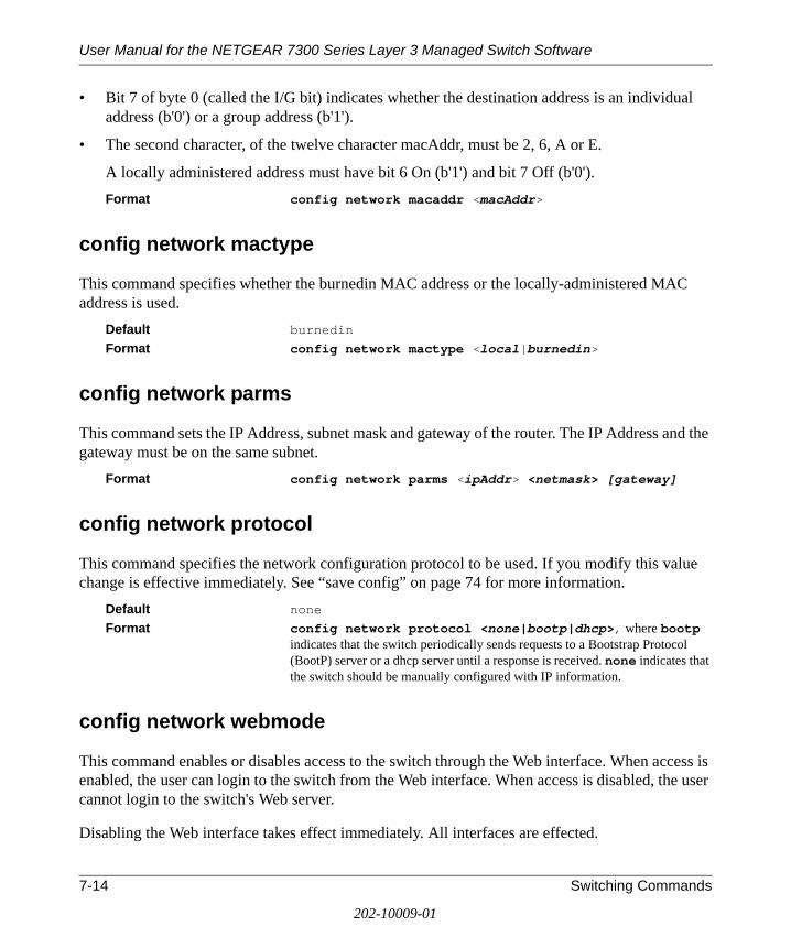
User Manual for the NETGEAR 7300 Series Layer 3 Managed Switch Software
7-14 Switching Commands
202-10009-01
• Bit 7 of byte 0 (called the I/G bit) indicates whether the destination address is an individual address (b'0') or a group address (b'1').
• The second character, of the twelve character macAddr, must be 2, 6, A or E.
A locally administered address must have bit 6 On (b'1') and bit 7 Off (b'0').Format config network macaddr <macAddr>
config network mactype
This command specifies whether the burnedin MAC address or the locally-administered MAC address is used.
Default burnedin
Format config network mactype <local|burnedin>
config network parms
This command sets the IP Address, subnet mask and gateway of the router. The IP Address and the gateway must be on the same subnet.
Format config network parms <ipAddr> <netmask> [gateway]
config network protocol
This command specifies the network configuration protocol to be used. If you modify this value change is effective immediately. See “save config” on page 74 for more information.
Default noneFormat config network protocol <none|bootp|dhcp>, where bootp
indicates that the switch periodically sends requests to a Bootstrap Protocol (BootP) server or a dhcp server until a response is received. none indicates that the switch should be manually configured with IP information.
config network webmode
This command enables or disables access to the switch through the Web interface. When access is enabled, the user can login to the switch from the Web interface. When access is disabled, the user cannot login to the switch's Web server.
Disabling the Web interface takes effect immediately. All interfaces are effected.
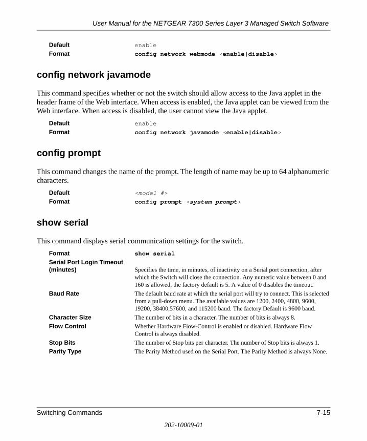
User Manual for the NETGEAR 7300 Series Layer 3 Managed Switch Software
Switching Commands 7-15
202-10009-01
Default enable
Format config network webmode <enable|disable>
config network javamode
This command specifies whether or not the switch should allow access to the Java applet in the header frame of the Web interface. When access is enabled, the Java applet can be viewed from the Web interface. When access is disabled, the user cannot view the Java applet.
Default enable
Format config network javamode <enable|disable>
config prompt
This command changes the name of the prompt. The length of name may be up to 64 alphanumeric characters.
Default <model #>
Format config prompt <system prompt>
show serial
This command displays serial communication settings for the switch.Format show serialSerial Port Login Timeout (minutes) Specifies the time, in minutes, of inactivity on a Serial port connection, after
which the Switch will close the connection. Any numeric value between 0 and 160 is allowed, the factory default is 5. A value of 0 disables the timeout.
Baud Rate The default baud rate at which the serial port will try to connect. This is selected from a pull-down menu. The available values are 1200, 2400, 4800, 9600, 19200, 38400,57600, and 115200 baud. The factory Default is 9600 baud.
Character Size The number of bits in a character. The number of bits is always 8. Flow Control Whether Hardware Flow-Control is enabled or disabled. Hardware Flow
Control is always disabled.Stop Bits The number of Stop bits per character. The number of Stop bits is always 1.Parity Type The Parity Method used on the Serial Port. The Parity Method is always None.

User Manual for the NETGEAR 7300 Series Layer 3 Managed Switch Software
7-16 Switching Commands
202-10009-01
config serial baudrate
This command specifies the communication rate of the terminal interface. The supported rates are 1200, 2400, 4800, 9600, 19200, 38400, 57600, 115200.
Default 9600Format config serial baudrate <speed>
config serial timeout
This command specifies the maximum connect time (in minutes) without console activity. A value of 0 indicates that a console can be connected indefinitely. The time range is 0 to 160.
Default 5Format config serial timeout <0 - 160>
show serviceport
This command displays service port configuration information.Format show serviceportIP Address The IP address of the interface. The factory default value is 0.0.0.0 Subnet Mask The IP subnet mask for this interface. The factory default value is 0.0.0.0 Default Gateway The default gateway for this IP interface. The factory default value is 0.0.0.0 ServPort Configuration Protocol Current Indicates what network protocol was used on the last, or current power-up cycle,
if any. Burnedin MAC Address The burnedin MAC address used for in-band connectivity.
config serviceport parms
This command sets the IP address, the netmask and the gateway of the router.Format config serviceport parms <ipAddr> <netmask> [gateway]
config serviceport protocol
This command specifies the servicePort configuration protocol. If you modify this value, the change takes effect immediately.
Format config serviceport protocol <none|bootp|dhcp>

User Manual for the NETGEAR 7300 Series Layer 3 Managed Switch Software
Switching Commands 7-17
202-10009-01
show snmpcommunity
This command displays SNMP community information.
Six communities are supported. You can add, change, or delete communities. The switch does not have to be reset for changes to take effect.
The SNMP agent of the switch complies with SNMP Version 1 (for more about the SNMP specification, see the SNMP RFCs). The SNMP agent sends traps through TCP/IP to an external SNMP manager based on the SNMP configuration (the trap receiver and other SNMP community parameters).
Format show snmpcommunity SNMP Community Name The community string to which this entry grants access. A valid entry is a case-
sensitive alphanumeric string of up to 16 characters. Each row of this table must contain a unique community name.
Client IP Address An IP address (or portion thereof) from which this device will accept SNMP packets with the associated community. The requesting entity's IP address is ANDed with the Subnet Mask before being compared to the IP Address. Note: that if the Subnet Mask is set to 0.0.0.0, an IP Address of 0.0.0.0 matches all IP addresses. The default value is 0.0.0.0
Client IP Mask A mask to be ANDed with the requesting entity's IP address before comparison with IP Address. If the result matches with IP Address then the address is an authenticated IP address. For example, if the IP Address = 9.47.128.0 and the corresponding Subnet Mask = 255.255.255.0 a range of incoming IP addresses would match, i.e. the incoming IP Address could equal 9.47.128.0 - 9.47.128.255. The default value is 0.0.0.0
Access Mode The access level for this community string. May be specified by selecting Read/Write or Read Only from the pull-down. Updates will be made to the switch by pressing the Submit button.
Status The status of this community access entry. When this object is set to enabled, if the Community Name for this row is not unique among all valid rows, the set request will be rejected. Community names may be made invalid by selecting disable. Rows may be deleted by selecting Delete. Updates will be made to the switch by pressing the Submit button.
config snmpcommunity accessmode
This command restricts access to switch information. The access mode can be read-only (also called public) or read/write (also called private).
Format config snmpcommunity accessmode <ro|rw> <name>
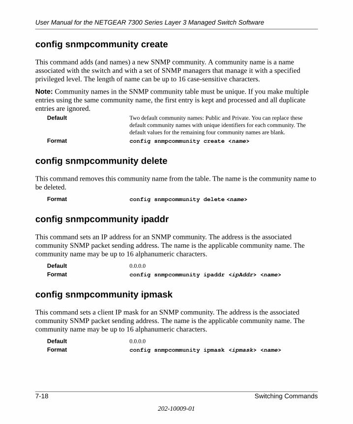
User Manual for the NETGEAR 7300 Series Layer 3 Managed Switch Software
7-18 Switching Commands
202-10009-01
config snmpcommunity create
This command adds (and names) a new SNMP community. A community name is a name associated with the switch and with a set of SNMP managers that manage it with a specified privileged level. The length of name can be up to 16 case-sensitive characters.
Note: Community names in the SNMP community table must be unique. If you make multiple entries using the same community name, the first entry is kept and processed and all duplicate entries are ignored.
Default Two default community names: Public and Private. You can replace these default community names with unique identifiers for each community. The default values for the remaining four community names are blank.
Format config snmpcommunity create <name>
config snmpcommunity delete
This command removes this community name from the table. The name is the community name to be deleted.
Format config snmpcommunity delete <name>
config snmpcommunity ipaddr
This command sets an IP address for an SNMP community. The address is the associated community SNMP packet sending address. The name is the applicable community name. The community name may be up to 16 alphanumeric characters.
Default 0.0.0.0Format config snmpcommunity ipaddr <ipAddr> <name>
config snmpcommunity ipmask
This command sets a client IP mask for an SNMP community. The address is the associated community SNMP packet sending address. The name is the applicable community name. The community name may be up to 16 alphanumeric characters.
Default 0.0.0.0Format config snmpcommunity ipmask <ipmask> <name>

User Manual for the NETGEAR 7300 Series Layer 3 Managed Switch Software
Switching Commands 7-19
202-10009-01
config snmpcommunity mode
This command activates or deactivates an SNMP community. If a community is enabled, an SNMP manager associated with this community manages the switch according to its access right. If the community is disabled, no SNMP requests using this community are accepted. In this case the SNMP manager associated with this community cannot manage the switch until the Status is changed back to Enable.
Default The default private and public communities are enabled by default. The four undefined communities are disabled by default.
Format config snmpcommunity mode <enable|disable> <name>
show snmptrap
This command displays SNMP trap receivers. Trap messages are sent across a network to an SNMP Network Manager. These messages alert the manager to events occurring within the switch or on the network. Six trap receivers are simultaneously supported.
Format show snmptrapSNMP Trap Name The community string of the SNMP trap packet sent to the trap manager. This
may be up to 16 alphanumeric characters. This string is case sensitive. IP Address The IP address to receive SNMP traps from this device. Enter 4 numbers
between 0 and 255 separated by periods. Status A pull down menu that indicates the receiver's status(enabled or disabled) and
allows the administrator/user to perform actions on this user entry: Enable - send traps to the receiver. Disable - do not send traps to the receiver. Delete - remove the table entry.
config snmptrap create
This command adds an SNMP trap name. The maximum length of name is 16 case-sensitive alphanumeric characters.
Default The default name for the six undefined community names is Delete.Format config snmptrap create <name> <ipAddr>
config snmptrap delete
This command deletes trap receivers for a community. Format config snmptrap delete <name> <ipaddr>

User Manual for the NETGEAR 7300 Series Layer 3 Managed Switch Software
7-20 Switching Commands
202-10009-01
config snmptrap ipaddr
This command assigns an IP address to a specified community name. The maximum length of name is 16 case-sensitive alphanumeric characters.
Note: IP addresses in the SNMP trap receiver table must be unique. If you make multiple entries using the same IP address, the first entry is retained and processed. All duplicate entries are ignored.
Format config snmptrap ipaddr <ipaddrold> <name> <ipaddrnew>
config snmptrap mode
This command activates or deactivates an SNMP trap. Enabled trap receivers are active (able to receive traps). Disabled trap receivers are inactive (not able to receive traps).
Format config snmptrap mode <enable|disable> <name> <ipaddr>
show trapflags
This command displays trap conditions. Configure which traps the switch should generate by enabling or disabling the trap condition. If a trap condition is enabled and the condition is detected, the switch's SNMP agent sends the trap to all enabled trap receivers. The switch does not have to be reset to implement the changes. Cold and warm start traps are always generated and cannot be disabled.
Format show trapflagsAuthentication Flag May be enabled or disabled by selecting the corresponding line on the pull-
down entry field. The factory default is enabled. Indicates whether authentication failure traps will be sent.
Link Up/Down Flag May be enabled or disabled by selecting the corresponding line on the pull-down entry field. The factory default is enabled. Indicates whether link status traps will be sent. Multiple Users Flag.
Multiple Users Flag May be enabled or disabled by selecting the corresponding line on the pull-down entry field. The factory default is enabled. Indicates whether a trap will be sent when the same user ID is logged into the switch more than once at the same time (either via telnet or serial port).
Spanning Tree Flag May be enabled or disabled by selecting the corresponding line on the pull-down entry field. The factory default is enabled. Indicates whether spanning tree traps will be sent.
Broadcast Storm Flag May be enabled or disabled by selecting the corresponding line on the pull-down entry field. The factory default is enabled. Indicates whether broadcast storm traps will be sent.

User Manual for the NETGEAR 7300 Series Layer 3 Managed Switch Software
Switching Commands 7-21
202-10009-01
config trapflags authentication
This command enables or disables the Authentication Flag.Default enableFormat config trapflags authentication <enable|disable>
config trapflags bcaststorm
This command enables or disables the broadcast storm trap. When enabled, broadcast storm traps are sent only if the broadcast storm recovery mode setting associated with the port is enabled (see “config switchconfig broadcast” on page 24).
Default enable
Format config trapflags bcaststorm <enable|disable>
config trapflags linkmode
This command enables or disables Link Up/Down traps for the entire switch. When enabled, link traps are sent only if the Link Trap flag setting associated with the port is enabled (see “config port linktrap” on page 26).
Default enable
Format config trapflags linkmode <enable|disable>
config trapflags multiusers
This command enables or disables Multiple User traps. When the traps are enabled, a Multiple User Trap is sent when a user logs in to the terminal interface (EIA 232 or telnet) and there is an existing terminal interface session.
Default enableFormat config trapflags multiusers <enable|disable>
config trapflags stpmode
This command enables or disables the sending of new root traps and topology change notification traps.
Default enableFormat config trapflags stpmode <enable|disable>
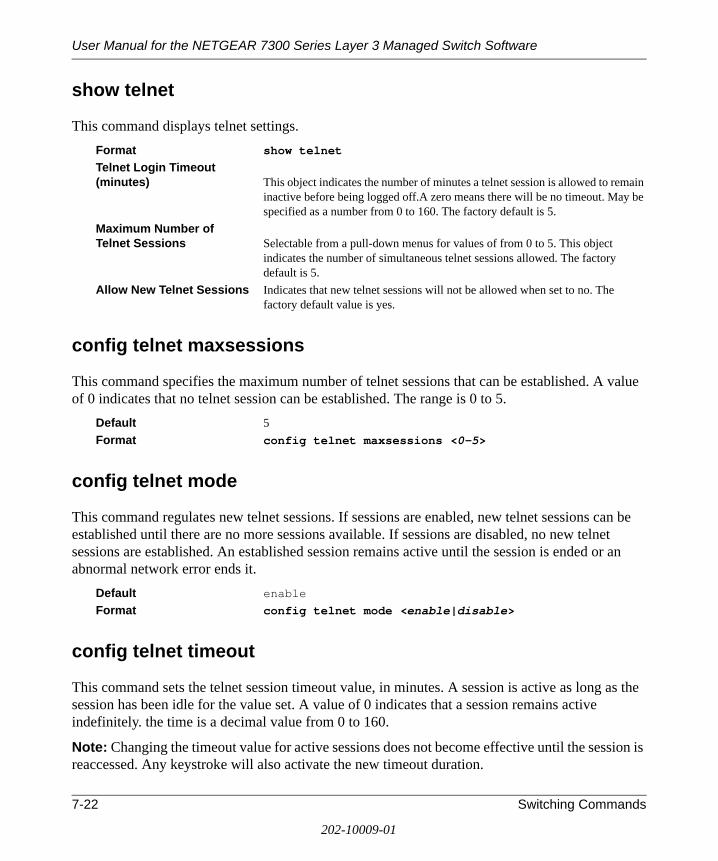
User Manual for the NETGEAR 7300 Series Layer 3 Managed Switch Software
7-22 Switching Commands
202-10009-01
show telnet
This command displays telnet settings.Format show telnet Telnet Login Timeout (minutes) This object indicates the number of minutes a telnet session is allowed to remain
inactive before being logged off.A zero means there will be no timeout. May be specified as a number from 0 to 160. The factory default is 5.
Maximum Number of Telnet Sessions Selectable from a pull-down menus for values of from 0 to 5. This object
indicates the number of simultaneous telnet sessions allowed. The factory default is 5.
Allow New Telnet Sessions Indicates that new telnet sessions will not be allowed when set to no. The factory default value is yes.
config telnet maxsessions
This command specifies the maximum number of telnet sessions that can be established. A value of 0 indicates that no telnet session can be established. The range is 0 to 5.
Default 5 Format config telnet maxsessions <0-5>
config telnet mode
This command regulates new telnet sessions. If sessions are enabled, new telnet sessions can be established until there are no more sessions available. If sessions are disabled, no new telnet sessions are established. An established session remains active until the session is ended or an abnormal network error ends it.
Default enableFormat config telnet mode <enable|disable>
config telnet timeout
This command sets the telnet session timeout value, in minutes. A session is active as long as the session has been idle for the value set. A value of 0 indicates that a session remains active indefinitely. the time is a decimal value from 0 to 160.
Note: Changing the timeout value for active sessions does not become effective until the session is reaccessed. Any keystroke will also activate the new timeout duration.

User Manual for the NETGEAR 7300 Series Layer 3 Managed Switch Software
Switching Commands 7-23
202-10009-01
Default 5 Format config telnet timeout <0-160>
show forwardingdb agetime
This command displays the timeout for address aging. In an IVL system, the [fdbid|all] parameter is required. In an SVL system, the [fdbid|all] parameter is not used and will be ignored if entered.
Default all Format show forwardingdb agetime [fdbid|all] Forwarding DB ID Fdbid (Forwarding database ID) indicates the forwarding database whose aging
timeout is to be shown. The all option is used to display the aging timeouts associated with all forwarding databases. This field displays the forwarding database ID in an IVL system. This field will not be displayed in an SVL system.
Agetime displays the address aging timeout for the associated forwarding database in IVL. In an SVL system, this will display the system's address aging timeout value in seconds.
config forwardingdb agetime
This command configures the forwarding database address aging timeout. In an IVL system, the [fdbid/all] parameter is required. In an SVL system, the [fdbid/all] parameter is not used and will be ignored if entered.
Default The default value for <10-1,000,000> is 300 secondsFormat config forwardingdb agetime <10-1,000,000> [fdbid/
all] Seconds The <seconds> parameter must be within the range of 10 to 1,000,000 seconds. Forwarding Database ID Fdbid (Forwarding database ID) indicates which forwarding database's aging
timeout is being configured. All is used to configure all forwarding database's agetime. In an SVL system, the [fdbid/all] parameter is not used and will be ignored if entered.
Device Configuration Commands
This section describes device configuration commands.

User Manual for the NETGEAR 7300 Series Layer 3 Managed Switch Software
7-24 Switching Commands
202-10009-01
show switchconfig
This command displays switch configuration information.Format show switchconfig Broadcast Storm Recovery Mode May be enabled or disabled by selecting the corresponding line on the pull-
down entry field. The factory default is disabled. 802.3x Flow Control Mode May be enabled or disabled by selecting the corresponding line on the pull-
down entry field. The factory default is disabled.
config switchconfig broadcast
This command enables or disables broadcast storm recovery mode. If the mode is enabled, broadcast storm recovery with high and low thresholds is implemented.
The threshold implementation follows a percentage pattern. If the broadcast traffic on any Ethernet port exceeds the high threshold percentage (as represented in “Broadcast Storm Recovery Thresholds” table) of the link speed, the switch discards the broadcasts traffic until the broadcast traffic returns to the low threshold percentage or less. The full implementation is depicted in the “Broadcast Storm Recovery Thresholds” table.
Format config switchconfig broadcast <enable/disable>
config switchconfig flowcontrol
This command enables or disables 802.3x flow control for the switch.
Note: This command only applies to full-duplex mode ports.Default enable
Format config switchconfig flowcontrol <enable/disable>
show port
This command displays port information.
Table 2. Broadcast Storm Recovery Thresholds
Link Speed High Low
10M 20 10
100M 5 2
1000M 5 2

User Manual for the NETGEAR 7300 Series Layer 3 Managed Switch Software
Switching Commands 7-25
202-10009-01
Format show port <slot.port|all>Slot.Port The physical slot and physical port.Type If not blank, this field indicates that this port is a special type of port. The
possible values are: Mon - this port is a monitoring port. Look at the Port Monitoring screens to find out more information. Lag - this port is a member of a Lag. Look at the Lag screens to find out more information. Probe - this port is a probe port. Look at the Port Mirroring screens to find out more information.
Admin Mode Selects the Port control administration state. The port must be enabled in order for it to be allowed into the network. - May be enabled or disabled by selecting the corresponding line on the pull-down entry field. The factory default is enabled.
Physical Mode Selects the desired port speed and duplex mode. If auto-negotiation support is selected, then the duplex mode and speed will be set from the auto-negotiation process. Note that the port's maximum capability (full duplex -100M) will be advertised. Otherwise, this object will determine the port's duplex mode and transmission rate. The factory default is Auto.
Physical Status Indicates the port speed and duplex mode. Link Status Indicates whether the Link is up or down. Link Trap This object determines whether or not to send a trap when link status changes.
The factory default is enabled. LACP Mode Displays whether LACP is enabled or disabled on this port.
config port adminmode
This command enables or disables a port.Default enable
Format config port adminmode <slot.port|all> <enable|disable>
config port flowcontrol
This command enables or disables flow control on the specified interface. Format config port flowcontrol <slot.port|all>
<enable|disable>

User Manual for the NETGEAR 7300 Series Layer 3 Managed Switch Software
7-26 Switching Commands
202-10009-01
config port linktrap
This command enables or disables link status traps by interface.
Note: This command is valid only when the Link Up/Down Flag is enabled. See “config trapflags linkmode” on page 21 for more information.
Format config port linktrap < slot.port|all> <enable|disable>
config port physicalmode
This command sets the speed and duplex setting for the interface. Format config port physicalmode <slot.port|all>
<100h|100f|10h|10f>
Acceptable values are:100h 100BASE-T half-duplex 100f 100BASE-T full duplex 10h 10BASE-T half duplex 10f 100BASE-T full duplex
config port lacpmode
This command enables or disables Link Aggregation Control Protocol (LACP) on a port. The possible values for <mode> are enable and disable. The default value is disable.
Format config port lacpmode <slot.port/all> <enable/disable>
config port autoneg
This command enables or disables automatic negotiation on a port. The possible values for <mode> are enable and disable. The default value is enable.
Format config port autoneg <slot.port/all> <enable/disable>
show lag
This command displays an overview of all link aggregations (LAGs) on the switch.Format show lag <logical slot.port|all>

User Manual for the NETGEAR 7300 Series Layer 3 Managed Switch Software
Switching Commands 7-27
202-10009-01
Logical Slot.Port The logical slot and the logical port.Lag Name The name of this lag. You may enter any string of up to 15 alphanumeric
characters. Link State Indicates whether the Link is up or down. Admin Mode May be enabled or disabled by selecting the corresponding line on the pull-
down entry field. The factory default is enabled. Link Trap Mode This object determines whether or not to send a trap when link status changes.
The factory default is enabled. STP Mode The Spanning Tree Protocol Administrative Mode associated with the port or
lag. The possible values are: Disable - Spanning tree is disabled for this port.Enable - Spanning tree is enabled for this port.
Mbr Ports A listing of the ports that are members of this lag, in slot.port notation. There can be a maximum of 8 ports assigned to a given lag.
Port Speed
config lag create
This command configures a new LAG and generates a logical slot and port number for it. Display this number using the “show lag” on page 26.
Note: Before including a port in a LAG, set the port physical mode. See “config port physicalmode” on page 26.
Format config lag create <name>
config lag addport
This command adds one port to the LAG. The first interface is a logical slot and port number of a configured LAG.
Note: Before adding a port to a LAG, set the physical mode of the port. See “config port physicalmode” on page 26.
Format config lag addport <logical slot.port> <slot.port>
config lag deleteport
This command deletes one or more ports from the LAG. The first interface is a logical slot and port number of a configured LAG, and the second interface is a valid slot and port number that is a member of any LAG or all (to delete all ports in the specified LAG).
Format config lag deleteport <logical slot.port> <slot.port|all>

User Manual for the NETGEAR 7300 Series Layer 3 Managed Switch Software
7-28 Switching Commands
202-10009-01
config lag adminmode
This command enables or disables a LAG. The interface is a logical slot and port for a configured LAG. The option all sets every configured LAG with the same administrative mode setting.
Format config lag adminmode <logical slot.port|all> <enable|disable>
config lag linktrap
This command enables or disables link trap notifications for the LAG. The interface is a logical slot and port for a configured LAG. The option all sets every configured LAG with the same administrative mode setting.
Default enableFormat config lag linktrap <logical slot.port|all>
<enable|disable>
config lag name
This command defines a name for the LAG. The interface is a logical slot and port for a configured LAG, and name is an alphanumeric string up to 15 characters. This command is used to modify the name that was associated with the LAG when it was created.
Format config lag name <logical slot.port|all> <name>
config lag deletelag
This command deletes an existing lag from the configuration. The interface is a logical slot and port for a configured LAG. The all option removes all configured LAGs.
Format config lags deletelag <logical slot.port|all>
config lag stpmode
This command sets the STP mode for a specific LAG. This is the value specified for STP Mode on the Port Configuration Menu. 802.1D mode is the default. The interface is a logical slot and port for a configured LAG. The all option sets all configured LAGs with the same option.
Format config lag stpmode <logical slot.port|all> <off|802.1d|fast>

User Manual for the NETGEAR 7300 Series Layer 3 Managed Switch Software
Switching Commands 7-29
202-10009-01
The mode is one of the following:802.1d IEEE 802.1D-compliant STP mode is used.fast Fast STP mode is used.off STP is turned off.
show vlan summary
This command displays a list of all configured VLANs.Format show vlan summaryVLAN ID There is a VLAN Identifier (VID) associated with each VLAN. The range of the
VLAN ID is 1 to 4094. VLAN Name A string associated with this VLAN as a convenience. It can be up to 16
alphanumeric characters long, including blanks. The default is blank. VLAN ID 1 always has a name of `Default`. This field is optional.
VLAN Type What type of VLAN this is. A VLAN can be the Default VLAN, (VLAN ID = 1), a static VLAN, one that is configured and permanently defined, or a Dynamic VLAN, one that is created by GVRP registration. In order to change a VLAN from Dynamic to Static, select Static from the Vlan Type pull-down entry field. Once the VLAN is selected, click on Submit. This will change the VLAN type to Static.
show vlan detailed
This command displays detailed information, including interface information, for a specific VLAN.
Format config vlan detailed <vlan id>, where the ID is a valid VLAN identification number
VLAN ID There is a VLAN Identifier (VID) associated with each VLAN. The range of the VLAN ID is 1 to 4094.
VLAN Name A string associated with this VLAN as a convenience. It can be up to 16 alphanumeric characters long, including blanks. The default is blank. VLAN ID 1 always has a name of `Default`. This field is optional.
VLAN Type What type of VLAN this is. A VLAN can be the Default VLAN, (VLAN ID = 1), a static VLAN, one that is configured and permanently defined, or a Dynamic VLAN, one that is created by GVRP registration. In order to change a VLAN from Dynamic to Static, select Static from the Vlan Type pull-down entry field. Once the VLAN is selected, click on Submit. This will change the VLAN type to Static.
Slot.Port Indicates by slot id and port number which port is controlled by the fields on this line. It is possible to set the parameters for all ports by using the selectors on the top line.

User Manual for the NETGEAR 7300 Series Layer 3 Managed Switch Software
7-30 Switching Commands
202-10009-01
Current Determines the degree of participation of this port in this VLAN. The permissible values are: Include - this port is always a member of this VLAN. This is equivalent to registration fixed in the IEEE 802.1Q standard. Exclude - this port is never a member of this VLAN. This is equivalent to registration forbidden in the IEEE 802.1Q standard. Autodetect - Specifies to allow the port to be dynamically registered in this VLAN via GVRP. The port will not participate in this VLAN unless a join request is received on this port. This is equivalent to registration normal in the IEEE 802.1Q standard.
Configured Determines the configured degree of participation of this port in this VLAN. The permissible values are: Include - this port is always a member of this VLAN. This is equivalent to registration fixed in the IEEE 802.1Q standard. Exclude - this port is never a member of this VLAN. This is equivalent to registration forbidden in the IEEE 802.1Q standard. Autodetect - specifies to allow the port to be dynamically registered in this VLAN via GVRP. The port will not participate in this VLAN unless a join request is received on this port. This is equivalent to registration normal in the IEEE 802.1Q standard.
Tagging Select the tagging behavior for this port in this VLAN. Tagged - specifies to transmit traffic for this VLAN as tagged frames. Untagged - specifies to transmit traffic for this VLAN as untagged frames.
config vlan create
This command creates a new VLAN and assigns it an ID. The ID is a valid VLAN identification number (ID 1 is reserved for the default VLAN) VLAN range is 2-4094.
Format config vlan create <2-4094>
config vlan delete
This command deletes an existing VLAN. The ID is a valid VLAN identification number (ID 1 is reserved for the default VLAN) VLAN range is 2-4094.
Format config vlan delete <2-4094>
config vlan name
This command changes the name of a VLAN. The name is an alphanumeric string of up to 16 characters, and the ID is a valid VLAN identification number. ID range is 1-4094.
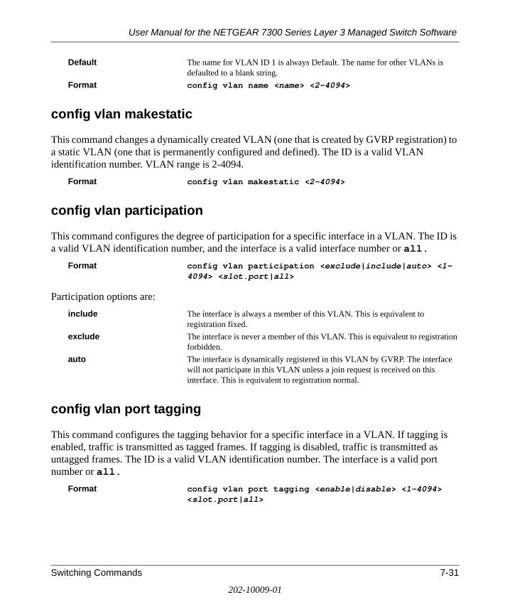
User Manual for the NETGEAR 7300 Series Layer 3 Managed Switch Software
Switching Commands 7-31
202-10009-01
Default The name for VLAN ID 1 is always Default. The name for other VLANs is defaulted to a blank string.
Format config vlan name <name> <2-4094>
config vlan makestatic
This command changes a dynamically created VLAN (one that is created by GVRP registration) to a static VLAN (one that is permanently configured and defined). The ID is a valid VLAN identification number. VLAN range is 2-4094.
Format config vlan makestatic <2-4094>
config vlan participation
This command configures the degree of participation for a specific interface in a VLAN. The ID is a valid VLAN identification number, and the interface is a valid interface number or all.
Format config vlan participation <exclude|include|auto> <1-4094> <slot.port|all>
Participation options are: include The interface is always a member of this VLAN. This is equivalent to
registration fixed.exclude The interface is never a member of this VLAN. This is equivalent to registration
forbidden.auto The interface is dynamically registered in this VLAN by GVRP. The interface
will not participate in this VLAN unless a join request is received on this interface. This is equivalent to registration normal.
config vlan port tagging
This command configures the tagging behavior for a specific interface in a VLAN. If tagging is enabled, traffic is transmitted as tagged frames. If tagging is disabled, traffic is transmitted as untagged frames. The ID is a valid VLAN identification number. The interface is a valid port number or all.
Format config vlan port tagging <enable|disable> <1-4094> <slot.port|all>

User Manual for the NETGEAR 7300 Series Layer 3 Managed Switch Software
7-32 Switching Commands
202-10009-01
show vlan port
This command displays VLAN port information. Format show vlan port <slot.port>Slot.Port Indicates by slot id and port number which port is controlled by the fields on this
line. It is possible to set the parameters for all ports by using the selectors on the top line.
Port VLAN ID The VLAN ID that this port will assign to untagged frames or priority tagged frames received on this port. The value must be for an existing VLAN. The factory default is 1.
Acceptable Frame Types Specifies the types of frames that may be received on this port. The options are 'VLAN only' and 'Admit All'. When set to 'VLAN only', untagged frames or priority tagged frames received on this port are discarded. When set to 'Admit All', untagged frames or priority tagged frames received on this port are accepted and assigned the value of the Port VLAN ID for this port. With either option, VLAN tagged frames are forwarded in accordance to the 802.1Q VLAN specification.
Ingress Filtering May be enabled or disabled by selecting the corresponding line on the pull-down entry field. When enabled, the frame is discarded if this port is not a member of the VLAN with which this frame is associated. In a tagged frame, the VLAN is identified by the VLAN ID in the tag. In an untagged frame, the VLAN is the Port VLAN ID specified for the port that received this frame. When disabled, all frames are forwarded in accordance with the 802.1Q VLAN bridge specification. The factory default is disabled.
GVRP
config vlan port pvid
This command changes the VLAN ID per interface.Default 1
Format config vlan port pvid <1-4094> <slot.port|all>
config vlan port acceptframe
This command sets the frame acceptance mode per interface. For VLAN Only mode, untagged frames or priority frames received on this interface are discarded. For Admit All mode, untagged frames or priority frames received on this interface are accepted and assigned the value of the interface VLAN ID for this port. With either option, VLAN tagged frames are forwarded in accordance with the IEEE 802.1Q VLAN Specification. VLAN ID range is 1-4094.
Default Admit All

User Manual for the NETGEAR 7300 Series Layer 3 Managed Switch Software
Switching Commands 7-33
202-10009-01
Format config vlan port acceptframe <all|vlan> <slot.port|all>
config vlan port ingressfilter
This command enables or disables ingress filtering. If ingress filtering is disabled, frames received with VLAN IDs that do not match the VLAN membership of the receiving interface are admitted and forwarded to ports that are members of that VLAN.
Default disableFormat config vlan port ingressfilter <enable|disable>
<slot.port|all>
show protocol
This command displays the Protocol-Based VLAN information for either the entire system, or for the indicated Group.
Format show protocol detailed <groupid/all>
Group Name This field displays the group name of an entry in the Protocol-based VLAN table.
Group ID This field displays the group identifier of the protocol group.Protocol(s) This field indicates the type of protocol(s) for this group. VLAN This field indicates the VLAN associated with this Protocol Group.Interface(s) This field lists the Slot.Port interface(s) that are associated with this Protocol
Group.
config protocol create
This command adds protocol-based VLAN group to the system. The <groupName> is a character string of 1 to 16 characters. When it is created, the protocol group will be assigned a unique number that will be used to identify the group in subsequent commands.
Format config protocol create <groupname>
config protocol delete
This command removes the protocol-based VLAN group that is identified by this <groupid>.Format config protocol delete <groupid>

User Manual for the NETGEAR 7300 Series Layer 3 Managed Switch Software
7-34 Switching Commands
202-10009-01
config protocol protocol add
This command adds the <protocol> to the protocol-based VLAN identified by <groupid>. A group may have more than one protocol associated with it. Each interface and protocol combination can only be associated with one group. If adding a protocol to a group causes any conflicts with interfaces currently associated with the group, this command will fail and the protocol will not be added to the group. The possible values for protocol are ip, arp, and ipx.
Default none
Format config protocol protocol add <groupid> <protocol>
config protocol protocol remove
This command removes the <protocol> from this protocol-based VLAN group that is identified by this <groupid>. The possible values for protocol are ip, arp, and ipx.
Default none
Format config protocol protocol remove <groupid> <protocol>
config protocol vlan add
This command attaches a <vlan> to the protocol-based VLAN identified by <groupid>. A group may only be associated with one VLAN at a time, however the VLAN association can be changed.
Default none
Format config protocol vlan add <groupid> <vlan>
config protocol vlan remove
This command removes the <vlan> from this protocol-based VLAN group that is identified by this <groupid>.
Default none
Format config protocol vlan remove <groupid> <vlan>

User Manual for the NETGEAR 7300 Series Layer 3 Managed Switch Software
Switching Commands 7-35
202-10009-01
config protocol interface add
This command adds the physical <slot.port> interface to the protocol-based VLAN identified by <groupid>. If <all> is selected, all physical interfaces will be added to this protocol group. A group may have more than one interface associated with it. Each interface and protocol combination can only be associated with one group. If adding an interface to a group causes any conflicts with protocols currently associated with the group, this command will fail and the interface(s) will not be added to the group.
Default none
Format config protocol interface add <groupid> <slot.port/all>
config protocol interface remove
This command removes the <interface> from this protocol-based VLAN group that is identified by this <groupid>. If <all> is selected, all ports will be removed from this protocol group.
Default none
Format config protocol interface remove <groupid> <slot.port/all>
show garp info
This command displays Generic Attributes Registration Protocol (GARP) information.Format show garp infoGMRP Admin Mode This displays the administrative mode of GARP Multicast Registration Protocol
(GMRP) for the system.GVRP Admin Mode This displays the administrative mode of GARP VLAN Registration Protocol
(GVRP) for the system.
show garp interface
This command displays Generic Attributes Registration Protocol (GARP) information for one or all interfaces.
Format show garp interface <slot.port/all>Interface This displays the slot.port of the interface that this row in the table describes.Join Timer Specifies the interval between the transmission of GARP PDUs registering (or
re-registering) membership for an attribute. Current attributes are a VLAN or multicast group. There is an instance of this timer on a per-Port, per-GARP
User Manual for the NETGEAR 7300 Series Layer 3 Managed Switch Software
7-36 Switching Commands
202-10009-01
participant basis. Permissible values are 10 to 100 centiseconds (0.1 to 1.0 seconds). The factory default is 20 centiseconds (0.2 seconds). The finest granularity of specification is 1 centisecond (0.01 seconds).
Leave Timer Specifies the period of time to wait after receiving an unregistered request for an attribute before deleting the attribute. Current attributes are a VLAN or multicast group. This may be considered a buffer time for another station to assert registration for the same attribute in order to maintain uninterrupted service. There is an instance of this timer on a per-Port, per-GARP participant basis. Permissible values are 20 to 600 centiseconds (0.2 to 6.0 seconds). The factory default is 60 centiseconds (0.6 seconds). The finest granularity of specification is 1 centisecond (0.01 seconds).
LeaveAll Timer This Leave All Time controls how frequently LeaveAll PDUs are generated. A LeaveAll PDU indicates that all registrations will shortly be deregistered. Participants will need to rejoin in order to maintain registration. There is an instance of this timer on a per-Port, per-GARP participant basis. The Leave All Period Timer is set to a random value in the range of LeaveAllTime to 1.5*LeaveAllTime. Permissible values are 200 to 6000 centiseconds (2 to 60 seconds). The factory default is 1000 centiseconds (10 seconds). The finest granularity of specification is 1 centisecond (0.01 seconds).
Port GMRP Mode Indicates the GMRP administrative mode for the port. It may be enabled or disabled. If this parameter is disabled, Join Time, Leave Time and Leave All Time have no effect. The factory default is disabled.
Port GVRP Mode Indicates the GVRP administrative mode for the port. It may be enabled or disabled. If this parameter is disabled, Join Time, Leave Time and Leave All Time have no effect. The factory default is disabled.
config garp gmrp adminmode
This command enables or disables GARP Multicast Registration Protocol (GMRP) on the system. The default value is disable.
Format config garp gmrp adminmode <enable/disable>
config garp gmrp interface mode
This command enables or disables GARP Multicast Registration Protocol on a selected interface. The <slot.port> parameter identifies the interface on which to configure the mode. If an interface which has GARP enabled is enabled for routing or is enlisted as a member of a LAG, GARP functionality will be disabled on that interface. GARP functionality will subsequently be re-enabled if routing is disabled and LAG membership is removed from an interface that has GARP enabled.
Default disableFormat config garp gmrp interface mode <slot.port/all> <enable/disable>

User Manual for the NETGEAR 7300 Series Layer 3 Managed Switch Software
Switching Commands 7-37
202-10009-01
config garp gvrp adminmode
This command enables or disables GVRP. Default disableFormat config garp gvrp adminmode <enable|disable>
config garp gvrp interface mode
This command enables or disables GVRP (GARP VLAN Registration Protocol) for a specific port. If GVRP is disabled, Join Time, Leave Time and Leave All Time have no effect.
Default disableFormat config garp gvrp interface mode <slot.port|all>
<enable|disable>
config garp jointimer
This command sets the GVRP join time per port and per GARP. Join time is the interval between the transmission of GARP Protocol Data Units (PDUs) registering (or re-registering) membership for a VLAN or multicast group.
This command has an effect only when GVRP is enabled. The time is from 10 to 100 (centiseconds)
Default 20 centiseconds (0.2 seconds)Format config garp jointimer <slot.port/all> <10-100>
config garp leavetimer
This command sets the GVRP leave time per port. Leave time is the time to wait after receiving an unregister request for a VLAN or a multicast group before deleting the VLAN entry. This can be considered a buffer time for another station to assert registration for the same attribute in order to maintain uninterrupted service.time is 20 to 600 (centiseconds).
Note: This command has an effect only when GVRP is enabled.Default 60 centiseconds (0.6 seconds)Format config garp leavetimer <slot.port/all> <20-600>

User Manual for the NETGEAR 7300 Series Layer 3 Managed Switch Software
7-38 Switching Commands
202-10009-01
config garp leavealltimer
This command sets how frequently Leave All PDUs are generated per port. A Leave All PDU indicates that all registrations will be unregistered. Participants would need to rejoin in order to maintain registration. The value applies per port and per GARP participation. The time may range from 200 to 6000 (centiseconds).
Note: This command has an effect only when GVRP is enabled.Default 1000 centiseconds (10 seconds)Format config garp leavealltimer <slot.port/all> <200-6000>
show igmpsnooping
This command displays IGMP Snooping information. Configured information is displayed whether or not IGMP Snooping is enabled. Status information is only displayed when IGMP Snooping is enabled.
Format show igmpsnooping Admin Mode This indicates whether or not IGMP Snooping is active on the switch.Query Interval Time This displays the IGMP Query Interval Time. This is the amount of time a
switch will wait for a report for a particular group on a particular interface before it sends a query on that interface. This value may be configured
Max Response Time This displays the amount of time the switch will wait after sending a query on an interface because it did not receive a report for a particular group on that interface. This value may be configured.
Multicast Router Present Expiration Time If a query is not received on an interface within this amount of time, the
interface is removed from the list of interfaces with multicast routers attached. This value may be configured.
Interfaces Enabled for GMP Snooping This is the list of interfaces on which IGMP Snooping is enabled. The following status values are only displayed when IGMP Snooping is enabled.
Multicast Control Frame Count This displays the number of multicast control frames that are processed by the
CPU.Data Frames Forwarded by the CPU This displays the number of data frames that are forwarded by the CPU.

User Manual for the NETGEAR 7300 Series Layer 3 Managed Switch Software
Switching Commands 7-39
202-10009-01
config igmpsnooping adminmode
This command enables or disables IGMP Snooping on the system. The default value is disable.Format config igmpsnooping adminmode <enable/disable>
config igmpsnooping groupmembershipinterval
This command sets the IGMP Group Membership Interval time on the system. The Group Membership Interval time is the amount of time in seconds that a switch will wait for a report from a particular group on a particular interface before deleting the interface from the entry. This value must be greater than the IGMP Maximum Response time value. The range is 1 to 3600 seconds.
Default 260 secondsFormat config igmpsnooping groupmembershipinterval <1-3600>
config igmpsnooping maxresponse
This command sets the IGMP Maximum Response time on the system. The Maximum Response time is the amount of time in seconds that a switch will wait after sending a query on an interface because it did not receive a report for a particular group in that interface. This value must be less than the IGMP Query Interval time value. The range is 1 to 3600 seconds.
Default 10 secondsFormat config igmpsnooping maxresponse <1-3600>
config igmpsnooping mcrtrexpiretime
This command sets the Multicast Router Present Expiration time on the system. This is the amount of time in seconds that a switch will wait for a query to be received on an interface before the interface is removed from the list of interfaces with multicast routers attached. The range is 0 to 3600 seconds. A value of 0 indicates an infinite timeout, i.e. no expiration.
Default 0 Format config igmpsnooping mcrtrexpiretime <0-3600>

User Manual for the NETGEAR 7300 Series Layer 3 Managed Switch Software
7-40 Switching Commands
202-10009-01
config igmpsnooping interface mode
This command enables or disables IGMP Snooping on a selected interface. The <slot.port/all> parameter identifies the interface on which to configure the mode. If an interface which has IGMP Snooping enabled is enabled for routing or is enlisted as a member of a LAG, IGMP Snooping functionality will be disabled on that interface. IGMP Snooping functionality will subsequently be re-enabled if routing is disabled or LAG membership is removed from an interface that has IGMP Snooping enabled.
Default disableFormat config igmpsnooping interface mode <slot.port/all> <enable/disable>
show mfdb table
This command displays the Multicast Forwarding Database (MFDB) information. If the command is entered with no parameter, the entire table is displayed. This is the same as entering the optional all parameter. The user can display the table entry for one MAC Address by specifying the MAC address a an optional parameter.
Format show mfdb table [macaddr/all]Mac Address A unicast MAC address for which the switch has forwarding and or filtering
information. The format is 6 or 8 two-digit hexadecimal numbers that are separated by colons, for example 01:23:45:67:89:AB. In an IVL system the MAC address will be displayed as 8 bytes. In an SVL system, the MAC address will be displayed as 6 bytes.
Type This displays the type of the entry. Static entries are those that are configured by the end user. Dynamic entries are added to the table as a result of a learning process or protocol.
Component The component that is responsible for this entry in the Multicast Forwarding Database. Possible values are IGMP Snooping, GMRP, and Static Filtering.
Description The text description of this multicast table entry. Interfaces The list of interfaces that are designated for forwarding (Fwd:) and filtering
(Flt:).Forwarding Interfaces The resultant forwarding list is derived from combining all the component’s
forwarding interfaces and removing the interfaces that are listed as the static filtering interfaces.
show mfdb gmrp
This command displays the GARP Multicast Registration Protocol (GMRP) entries in the Multicast Forwarding Database (MFDB) table.
Format show mfdb gmrp

User Manual for the NETGEAR 7300 Series Layer 3 Managed Switch Software
Switching Commands 7-41
202-10009-01
Mac Address A unicast MAC address for which the switch has forwarding and or filtering information. The format is 6 or 8 two-digit hexadecimal numbers that are separated by colons, for example 01:23:45:67:89:AB. In an IVL system the MAC address will be displayed as 8 bytes. In an SVL system, the MAC address will be displayed as 6 bytes.
Type This displays the type of the entry. Static entries are those that are configured by the end user. Dynamic entries are added to the table as a result of a learning process or protocol.
Description The text description of this multicast table entry. Interfaces The list of interfaces that are designated for forwarding (Fwd:) and filtering
(Flt:).
show mfdb igmpsnooping
This command displays the IGMP Snooping entries in the Multicast Forwarding Database (MFDB) table.
Format show mfdb igmpsnoopingMac Address A unicast MAC address for which the switch has forwarding and or filtering
information. The format is 6 or 8 two-digit hexadecimal numbers that are separated by colons, for example 01:23:45:67:89:AB. In an IVL system the MAC address will be displayed as 8 bytes. In an SVL system, the MAC address will be displayed as 6 bytes.
Type This displays the type of the entry. Static entries are those that are configured by the end user. Dynamic entries are added to the table as a result of a learning process or protocol.
Description The text description of this multicast table entry. Interfaces The list of interfaces that are designated for forwarding (Fwd:) and filtering
(Flt:).
show mfdb staticfiltering
This command displays the Static Filtering entries in the Multicast Forwarding Database (MFDB) table.
Format show mfdb staticfilteringMac Address A unicast MAC address for which the switch has forwarding and or filtering
information. The format is 6 or 8 two-digit hexadecimal numbers that are separated by colons, for example 01:23:45:67:89:AB. In an IVL system the MAC address will be displayed as 8 bytes. In an SVL system, the MAC address will be displayed as 6 bytes.
Type This displays the type of the entry. Static entries are those that are configured by the end user. Dynamic entries are added to the table as a result of a learning process or protocol.

User Manual for the NETGEAR 7300 Series Layer 3 Managed Switch Software
7-42 Switching Commands
202-10009-01
Description The text description of this multicast table entry. Interfaces The list of interfaces that are designated for forwarding (Fwd:) and filtering
(Flt:).
show mfdb stats
This command displays the Multicast Forwarding Database (MFDB) statistics. Format show mfdb statsTotal Entries This displays the total number of entries that can possibly be in the Multicast
Forwarding Database table.Most MFDB Entries Ever Used This displays the largest number of entries that have been present in the
Multicast Forwarding Database table. This value is also known as the MFDB high-water mark.
Current Entries This displays the current number of entries in the Multicast Forwarding Database table.
show mirroring
This command displays the Port Mirroring information for the system. Format show mirroring Port Mirroring Mode Indicates whether the Port Mirroring feature is enabled or disabled. The possible
values are enable and disable.Probe Port Slot.Port Is the slot.port that is configured as the probe port. If this value has not been
configured, 'Not Configured' will be displayed.Mirrored Port Slot.Port Is the slot.port that is configured as the mirrored port. If this value has not been
configured, 'Not Configured' will be displayed.
config mirroring create
This command configures a probe port and a mirrored port for Port Mirroring. The first slot.port is the probe port and the second slot.port is the mirrored port. If this command is executed while port mirroring is enabled, it will have the effect of changing the probe and mirrored port values.
Format config mirroring create <slot.port> <slot.port>

User Manual for the NETGEAR 7300 Series Layer 3 Managed Switch Software
Switching Commands 7-43
202-10009-01
config mirroring delete
This command removes the port mirroring designation from both the probe port and the mirrored port and removes the probe port from all VLANs. The port must be manually re-added to any desired VLANs.
Format config mirroring delete
config mirroring mode
This command configures the Port Mirroring mode. The possible values are enable and disable. The default value is disable. The probe and mirrored ports must be configured before port mirroring can be enabled. If enabled, the probe port will mirror all traffic received and transmitted on the physical mirrored port. It is not necessary to disable port mirroring before modifying the probe and mirrored ports.
Default disableFormat config mirroring mode <enable|disable>
show macfilter
This command displays the Static MAC Filtering information for all Static MAC Filters. If <all> is selected, all the Static MAC Filters in the system are displayed. If a macaddr is entered, a vlan must also be entered and the Static MAC Filter information will be displayed only for that MAC address and VLAN.
Format show macfilter <macaddr vlan/all>MAC Address The MAC Address of the static MAC filter entry.VLAN ID The VLAN ID of the static MAC filter entry.Source Port(s) Indicates the source port filter set's slot and port(s).Destination Port(s) Indicates the destination port filter set's slot and port(s).
config macfilter create
This command adds a static MAC filter entry for the MAC address <macaddr> on the VLAN <vlan>. The <macaddr> parameter must be specified as a 6-byte hexadecimal number in the format of b1:b2:b3:b4:b5:b6.
The restricted MAC Addresses are: 00:00:00:00:00:00, 01:80:C2:00:00:00 to 01:80:C2:00:00:0F, 01:80:C2:00:00:20 to 01:80:C2:00:00:21, and FF:FF:FF:FF:FF:FF.
User Manual for the NETGEAR 7300 Series Layer 3 Managed Switch Software
7-44 Switching Commands
202-10009-01
The <vlan> parameter must identify a valid VLAN.
Up to 100 static MAC filters may be created.Format config macfilter create <macaddr> <vlan>
config macfilter remove
This command removes all filtering restrictions and the static MAC filter entry for the MAC address <macaddr> on the VLAN <vlan>. The <macaddr> parameter must be specified as a 6-byte hexadecimal number in the format of b1:b2:b3:b4:b5:b6.
The <vlan> parameter must identify a valid VLAN.Format config macfilter remove <macaddr> <vlan>
config macfilter addsrc
This command adds the <slot.port> to the source filter set for the MAC filter with the MAC address of <macaddr> and VLAN of <vlan>. The <macaddr> parameter must be specified as a 6-byte hexadecimal number in the format of b1:b2:b3:b4:b5:b6.
The <vlan> parameter must identify a valid VLAN.
The <slot.port> parameter identifies the source port to be added to the source port filter set for the MAC filter.
If all is selected, all ports will be added to the source port filter set.Format config macfilter addsrc <macaddr> <vlan>
<slot.port|all>
config macfilter delsrc
This command removes a port from the source filter set for the MAC filter with the MAC address of <macaddr> and VLAN of <vlan>. The <macaddr> parameter must be specified as a 6-byte hexadecimal number in the format of b1:b2:b3:b4:b5:b6.
The <vlan> parameter must identify a valid VLAN.
The <slot.port> parameter identifies the source port to be removed from the source port filter set for the MAC filter.

User Manual for the NETGEAR 7300 Series Layer 3 Managed Switch Software
Switching Commands 7-45
202-10009-01
If all is selected, all ports will be removed from the source port filter set.Format config macfilter delsrc <macaddr> <vlan>
<slot.port|all>
config macfilter adddest
This command adds the <slot.port> to the destination filter set for the MAC filter with the given <macaddr> and VLAN of <vlan>. The <macaddr> parameter must be specified as a 6-byte hexadecimal number in the format of b1:b2:b3:b4:b5:b6.
The <vlan> parameter must identify a valid VLAN.
The <slot.port> parameter identifies the destination port to be added to the destination port filter set for the MAC filter.
If all is selected, all ports will be added to the destination port filter set.Format config macfilter adddest <macaddr> <vlan>
<slot.port|all>
config macfilter deldest
This command removes a port from the destination filter set for the MAC filter with the given <macaddr> and VLAN of <vlan>. The <macaddr> parameter must be specified as a 6-byte hexadecimal number in the format of b1:b2:b3:b4:b5:b6.
The <vlan> parameter must identify a valid VLAN.
The <slot.port> parameter identifies the destination port to be removed from the destination port filter set for the MAC filter.
If all is selected, all ports will be removed from the destination port filter set.Format config macfilter deldest <macaddr> <vlan>
<slot.port|all>
Spanning Tree Commands
This section provides detailed explanation of the spanning tree commands. The commands are divided into two functional groups:

User Manual for the NETGEAR 7300 Series Layer 3 Managed Switch Software
7-46 Switching Commands
202-10009-01
• Show commands display spanning tree settings, statistics, and other information.
• Config commands configure features and options of the switch. For every config command there is a show command that displays the config setting.
This section is organized by configuration type:
• System information and statistics commands
• Bridge and CIST commands
• MSTI commands
• Modified commands
• Obsolete commands
show spanningtree summary
This command displays spanning tree settings and parameters for the switch. Format show spanningtree summarySpanning Tree Adminmode Enabled or disabled.Spanning Tree Version Version of 802.1 currently supported (IEEE 802.1s, IEEE 802.1w, or IEEE
802.1d) based upon the Force Protocol Version parameter.Configuration Name TConfigured name.Configuration Revision Level Configured value.Configuration Digest Key Calculated value.Configuration Format Selector Configured value.MST Instances List of all multiple spanning tree instances configured on the switch.
config spanningtree adminmode
This command sets the spanningtree operational mode. While disabled, the spanningtree configuration is retained and can be changed, but it is not activated.
Default disableFormat config spaningtree adminmode <enable/disable>

User Manual for the NETGEAR 7300 Series Layer 3 Managed Switch Software
Switching Commands 7-47
202-10009-01
config spanningtree forceversion
This command sets the Force Protocol Version parameter to a new value. The <version> can be one of the following:
• 802.1d - ST BPDUs are transmitted rather than MST BPDUs (IEEE 802.1d functionality supported)
• 802.1w - RST BPDUs are transmitted rather than MST BPDUs (IEEE 802.1w functionality supported)
• 802.1s - MST BPDUs are transmitted (IEEE 802.1s functionality supported)Default 802.1sFormat config spanningtree forceversion <802.1d/802.1w/
802.1s>
config spanningtree configuration name
This command sets the Configuration Identifier Name for use in identifying the configuration that this switch is currently using. The <name> is a string of at most 32 characters.
Default The base MAC address displayed using hexadecimal notation as specified in IEEE 802 standard.
Format config spanningtree configuration name <name>
config spanningtree configuration revision
This command sets the Configuration Identifier Revision Level for use in identifying the configuration that this switch is currently using. The <revision> is a number in the range of 0 to 65535.
Default 0Format config spanningtree configuration revision <0-65535>
show spanningtree port
This command displays the settings and parameters for a specific switch port within the common and internal spanning tree. The <slot.port> is the desired switch port.
Format show spanningtree port <slot.port>Port mode Enabled or disabled.

User Manual for the NETGEAR 7300 Series Layer 3 Managed Switch Software
7-48 Switching Commands
202-10009-01
Port Up Time Since Counters Last Cleared Time since port was reset, displayed in days, hours, minutes, and seconds.STP BPDUs Transmitted Spanning Tree Protocol Bridge Protocol Data Units sent.STP BPDUs Received Spanning Tree Protocol Bridge Protocol Data Units received.RST BPDUs Transmitted Rapid Spanning Tree Protocol Bridge Protocol Data Units sent.RST BPDUs Received Rapid Spanning Tree Protocol Bridge Protocol Data Units received.MSTP BPDUs Transmitted Multiple Spanning Tree Protocol Bridge Protocol Data Units sent.MSTP BPDUs Received Multiple Spanning Tree Protocol Bridge Protocol Data Units received.
config spanningtree port migrationcheck
This command forces the specified port to transmit RST or MST BPDUs. The port <slot.port> is the desired switch port. To set the migration check for all ports with a single command, "all" can be specified. Note that the forceversion parameter for the switch must be set to 802.1w or 802.1s.
Default disableFormat config spanningtree port migrationcheck <slot.port/
all> <enable/disable>
config spanningtree port mode
This command sets the Administrative Switch Port State to a new value for the specified port. The port <slot.port> is the desired switch port. To enable or disable all ports with a single command, "all" can be specified. Note that only 4095 ports can be enabled.
Default disableFormat config spanningtree port mode <slot.port/all>
<enable/disable>
show spanningtree bridge
This command displays spanning tree settings for the bridge. Format show spanningtree bridgeBridge Priority Configured value.Bridge Identifier Bridge Max Age TConfigured value.Bridge Hello Time Configured value.Bridge Forward Delay Configured value.Bridge Hold Time Minimum time between transmission of Configuration Bridge Protocol Data
Units (BPDUs).

User Manual for the NETGEAR 7300 Series Layer 3 Managed Switch Software
Switching Commands 7-49
202-10009-01
config spanningtree bridge maxage
This command sets the Bridge Max Age parameter to a new value for the common and internal spanning tree. The maxage <value> is in whole seconds within a range of 6 to 40, with the value being less than or equal to "2 times (Bridge Forward Delay - 1)".
Default 20Format config spanningtree bridge maxage <6-40>
config spanningtree bridge hellotime
This command sets the Hello Time parameter to a new value for the common and internal spanning tree. The hellotime <value> is in whole seconds within a range of 1 to 10 with the value being less than or equal to "(Bridge Max Age / 2) - 1".
Default 2Format config spanningtree bridge hellotime <1-10>
config spanningtree bridge forwarddelay
This command sets the Bridge Forward Delay parameter to a new value for the common and internal spanning tree. The forwarddelay <value> is in whole seconds within a range of 4 to 30, with the value being greater than or equal to "(Bridge Max Age / 2) + 1".
Default 15Format config spanningtree bridge forwarddelay <4-30>
config spanningtree bridge priority
This command sets the Bridge Priority parameter to a new value for the common and internal spanning tree. The bridge priority <value> is a number within a range of 0 to 61440. The twelve least significant bits will be masked according to the 802.1s specification. This will cause the priority to be rounded down to the next lower valid priority.
Default 32768Format config spanningtree bridge priority <0-61440>
show spanningtree cst detailed
This command displays spanning tree settings for the common and internal spanning tree.

User Manual for the NETGEAR 7300 Series Layer 3 Managed Switch Software
7-50 Switching Commands
202-10009-01
Format show spanningtree cst detailedBridge Priority Configured value.Bridge Identifier Time Since Topology Change In seconds.Topology Change Count Number of times changed.Topology Change Boolean value of the Topology Change parameter for the switch indicating if a
topology change is in progress on any port assigned to the common and internal spanning tree.
Designated Root Root Path Cost Value of the Root Path Cost parameter for the common and internal spanning
tree. Root Port Identifier Derived value.Root Port Max Age Derived value.Root Port Bridge Forward Delay Derived value.Hello Time Configured value.Bridge Hold Time Minimum time between transmission of Configuration Bridge Protocol Data
Units (BPDUs).CST Regional Root Regional Root Path Cost Associated FIDs List of forwarding database identifiers currently associated with this instance.Associated VLANs List of VLAN IDs currently associated with this instance.
show spanningtree cst port summary
This command displays the status of one or all ports within the common and internal spanning tree. The parameter <slot.port/all> indicates the desired switch port or all ports.
Format show spanningtree cst port summary <slot.port/all>MST Instance ID CSTSlot.Port The interface being displayed.Type Currently not used.STP State The forwarding state of the port in the specified spanning tree instance.Port Role The role of the specified port within the spanning tree.Link Status The operational status of the link. Possible values are “Up” or “Down”.Link Trap The link trap configuration for the specified interface.

User Manual for the NETGEAR 7300 Series Layer 3 Managed Switch Software
Switching Commands 7-51
202-10009-01
show spanningtree cst port detailed
This command displays the settings and parameters for a specific switch port within the common and internal spanning tree. The <slot.port> is the desired switch port
Format show spanningtree cst port detailed <slot.port>Port Identifier The port identifier for this port within the CST.Port Priority The priority of the port within the CST.Port Forwarding State The forwarding state of the port within the CST.Port Role The role of the specified interface within the CST.Port Path Cost The configured path cost for the specified interface.Designated Root Identifier of the designated root for this port within the CST.Designated Port Cost Path Cost offered to the LAN by the Designated Port.Designated Bridge The bridge containing the designated port.Designated Port Identifier Port on the Designated Bridge that offers the lowest cost to the LAN. Topology Change Acknowledgement Value of flag in next Configuration Bridge Protocol Data Unit (BPDU)
transmission indicating if a topology change is in progress for this port.Hello Time The hello time in use for this port.Edge Port The configured value indicating if this port is an edge port.Edge Port Status The derived value of the edge port status. True if operating as an edge port; false
otherwise.Point To Point MAC Status Derived value indicating if this port is part of a point to point link.CST Regional Root The regional root identifier in use for this port.CST Port Cost The configured path cost for this port.
config spanningtree cst port pathcost
This command sets the Path Cost to a new value for the specified port in the common and internal spanning tree. The <slot.port> is the desired switch port. The pathcost <value> can be specified as a number in the range of 1 to 200000000 or auto. If "auto" is specified, the pathcost value will be set based on Link Speed.
Default autoFormat config spanningtree cst port pathcost <slot.port> <1-
200000000/auto>

User Manual for the NETGEAR 7300 Series Layer 3 Managed Switch Software
7-52 Switching Commands
202-10009-01
config spanningtree cst port priority
This command sets the Port Priority to a new value for use within the common and internal spanning tree. The <slot.port> is the desired switch port. The priority <value> is a number in the range of 0 to 240 in increments of 16.
Default 128Format config spanningtree cst port priority <slot.port> <0-
240>
config spanningtree cst port edgeport
This command specifies if a port is an Edge Port within the common and internal spanning tree. This will allow the port to transition to Forwarding State without delay. The <slot.port> is the desired switch port. The edgeport <value> can either be "true" or "false".
Default falseFormat config spanningtree cst port edgeport <slot.port>
<true/false>
config spanningtree mst create
This command adds a multiple spanning tree instance to the switch. The instance <mstid> is a number within a range of 1 to 4094, that corresponds to the new instance ID to be added. The maximum number of multiple instances supported by managed switch software is 4.
Format config spanningtree mst create <mstid>
config spanningtree mst delete
This command removes a multiple spanning tree instance from the switch and reallocates all VLANs allocated to the deleted instance to the common and internal spanning tree. The instance <mstid> is a number that corresponds to the desired existing multiple spanning tree instance to be removed.
Format config spanningtree mst delete <mstid>

User Manual for the NETGEAR 7300 Series Layer 3 Managed Switch Software
Switching Commands 7-53
202-10009-01
config spanningtree mst vlan add
This command adds an association between a multiple spanning tree instance and a VLAN. The VLAN will no longer be associated with the common and internal spanning tree. The instance <mstid> is a number that corresponds to the desired existing multiple spanning tree instance. The <vlan> corresponds to an existing VLAN ID.
Format config spanningtree mst vlan add <mstid> <vlan>
config spanningtree mst vlan remove
This command removes an association between a multiple spanning tree instance and a VLAN. The VLAN will again be associated with the common and internal spanning tree. The instance <mstid> is a number that corresponds to the desired existing multiple spanning tree instance. The <vlan> corresponds to an existing VLAN ID.
Format config spanningtree mst vlan remove <mstid> <vlan>
config spanningtree mst priority
This command sets the bridge priority for a specific multiple spanning tree instance. The instance <mstid> is a number that corresponds to the desired existing multiple spanning tree instance. The priority <value> is a number within a range of 0 to 61440 in increments of 4096.
Default 32768Format config spanningtree mst priority <mstid> <0-61440>
config spanningtree mst port pathcost
This command sets the path cost for a specific port within a multiple spanning tree instance. The instance <mstid> is a number that corresponds to the desired existing multiple spanning tree instance. The <slot.port> is the desired switch port. The pathcost can be specified as a number in the range of 1 to 200000000 or auto. If "auto" is specified, the pathcost value will be set based on Link Speed.
Default autoFormat config spanningtree mst port pathcost <mstid>
<slot.port> <1-200000000/auto>

User Manual for the NETGEAR 7300 Series Layer 3 Managed Switch Software
7-54 Switching Commands
202-10009-01
config spanningtree mst port priority
This command sets the priority for a specific port within a specific multiple spanning tree instance. The instance <mstid> is a number that corresponds to the desired existing multiple spanning tree instance. The <slot.port> is the desired switch port. The priority <value> is a number in the range of 0 to 240 in increments of 16.
Default 128Format config spanningtree mst port priority <mstid>
<slot.port> <0-240>
show spanningtree mst summary
This command displays summary information about all multiple spanning tree instances in the switch.
Format show spanningtree mst summaryMST Instance ID List List of multiple spanning trees IDs currently configured.For each MSTID: Associated FIDs List of forwarding database identifiers associated with this instance.Associated VLANs List of VLAN IDs associated with this instance.
show spanningtree mst detailed
This command displays settings and parameters for the specified multiple spanning tree instance. The instance <mstid> is a number that corresponds to the desired existing multiple spanning tree instance ID.
Format show spanningtree mst detailed <mstid>MST Instance ID MST Bridge Priority Time Since Topology Change Time in seconds.Topology Change Count Number of times the topology has changed for this multiple spanning tree
instance.Topology Change in Progress Value of the Topology Change parameter for the multiple spanning tree instance. Designated Root Identifier of the Regional Root for this multiple spanning tree instance.Root Path Cost Path Cost to the Designated Root for this multiple spanning tree instance.Root Port Identifier Port to access the Designated Root for this multiple spanning tree instance.Associated FIDs List of forwarding database identifiers associated with this instance.Associated VLANs List of VLAN IDs associated with this instance.

User Manual for the NETGEAR 7300 Series Layer 3 Managed Switch Software
Switching Commands 7-55
202-10009-01
show spanningtree mst port summary
This command displays the settings of one or all ports within the specified multiple spanning tree instance. The parameter <mstid> indicates a particular MST instance. The parameter <slot.port/all> indicates the desired switch port or all ports.
Format show spanningtree mst port summary <mstid> <slot.port/all>
MST Instance ID The MST instance associated with this port.Slot.Port The interface being displayed.Type Currently not used.STP State The forwarding state of the port in the specified spanning tree instance.Port Role The role of the specified port within the spanning tree.Link Status The operational status of the link. Possible values are “Up” or “Down”.Link Trap The link trap configuration for the specified interface.
show spanningtree mst port detailed
This command displays the detailed settings and parameters for a specific switch port within a particular multiple spanning tree instance. The instance <mstid> is a number that corresponds to the desired existing multiple spanning tree instance. The <slot.port> is the desired switch port.
Format show spanningtree mst port detailed <mstid> <slot.port>
MST Instance ID Port Identifier Port Priority Port Forwarding State Current spanning tree state of this port.Port Role Port Path Cost Configured value of the Internal Port Path Cost parameter.Designated Root The Identifier of the designated root for this port. Designated Port Cost Path Cost offered to the LAN by the Designated Port.Designated Bridge Bridge Identifier of the bridge with the Designated Port. Designated Port Identifier Port on the Designated Bridge that offers the lowest cost to the LAN.
show spanningtree vlan
This command displays the association between a VLAN and a multiple spanning tree instance. The <vlan> corresponds to an existing VLAN ID.
Format show spanningtree vlan <vlan>

User Manual for the NETGEAR 7300 Series Layer 3 Managed Switch Software
7-56 Switching Commands
202-10009-01
VLAN Identifier Associated Instance Identifier for the associated multiple spanning tree instance or "CST" if
associated with the common and internal spanning tree.
User Account Management Commands
These commands manage user accounts.
show users
This command displays the configured user names and their settings. This command is only available for users with readwrite privileges. The SNMPv3 fields will only be displayed if SNMP is available on the system.
Format show users User Name The name the user will use to login using the serial port, Telnet or Web. A new
user may be added to the switch by entering a name in a blank entry. The user name may be up to 8 characters, and is not case sensitive. Two users are included as the factory default, admin and guest.
Access Mode Shows whether the operator is able to change parameters on the switch(Read/Write) or is only able to view them(Read Only). As a factory default, admin has Read/Write access and guest has Read Only access. There can only be one Read/Write user and up to 5 Read Only users.
SNMPv3AccessMode This field displays the SNMPv3 Access Mode. If the value is set to ReadWrite, the SNMPv3 user will be able to set and retrieve parameters on the system. If the value is set to ReadOnly, the SNMPv3 user will only be able to retrieve parameter information. The SNMPv3 access mode may be different than the CLI and Web access mode.
SNMPv3Authentication This field displays the authentication protocol to be used for the specified login user.
SNMPv3Encryption This field displays the encryption protocol to be used for the specified login user.
config users add
This command adds a new user (account) if space permits. The account <name> is up to eight alphanumeric characters. The <name> is not case-sensitive.
Six user names can be defined.Format config users add <name>
User Manual for the NETGEAR 7300 Series Layer 3 Managed Switch Software
Switching Commands 7-57
202-10009-01
config users passwd
This command changes the password of an existing operator. The password is up to eight alphanumeric characters. The name and password are not case-sensitive.
When a password is changed, a prompt will ask for the operator’s former password. If none, press enter.
Default Blank (indicating no password)Format config users passwd <user>
config users delete
This command removes an operator.Format config users delete <name>Note: The admin user account cannot be deleted.
config users snmpv3 authentication
This command specifies the authentication protocol to be used for the specified login user. The valid authentication protocols are none, md5 or sha. If md5 or sha are specified, the user login password will be used as the snmpv3 authentication password. The <user> is the login user name for which the specified authentication protocol will be used.
Default no authenticationFormat config users snmpv3 authentication <user> <none/md5/
sha>
config users snmpv3 encryption
This command specifies the encryption protocol and key to be used for the specified login user. The valid encryption protocols are none or des. The des protocol requires a key, which can be specified on the command line. The key may be up to 16 characters long. If the des protocol is specified but a key is not provided, the user will be prompted for the key. If none is specified, a key must not be provided. The <user> is the login user name for which the specified encryption protocol will be used.
Default no encryptionFormat config users snmpv3 encryption <user> <none/des [key]>

User Manual for the NETGEAR 7300 Series Layer 3 Managed Switch Software
7-58 Switching Commands
202-10009-01
config users snmpv3 accessmode
This command specifies the snmpv3 access privileges for the specified login user. The valid accessmode values are readonly or readwrite. The <user> is the login user name for which the specified access mode will apply.
Default readwrite for admin user; readonly for all other usersFormat config users snmpv3 accessmode <user> <readonly/
readwrite>
show loginsession
This command displays current telnet and serial port connections to the switch. Format show loginsession ID Login Session ID.User Name The name the user will use to login using the serial port or Telnet. A new user
may be added to the switch by entering a name in a blank entry. The user name may be up to 8 characters, and is not case sensitive. Two users are included as the factory default, admin and guest.
Connection From IP address of the telnet client machine or EIA-232 for the serial port connection.Idle Time Time this session has been idle.Session Time Total time this session has been connected.
config loginsession close
This command closes a telnet session.Format config loginsession close <sessionID/all>
Security Commands
This section describes commands used for configuring security settings for login users and port users.
This command permanently saves configuration changes to Non-Volatile Random Access Memory (NVRAM).
Format save config

User Manual for the NETGEAR 7300 Series Layer 3 Managed Switch Software
Switching Commands 7-59
202-10009-01
config radius maxretransmit
This command sets the maximum number of times a request packet is retransmitted when no response is received from the RADIUS server. The maxretransmit value is an integer in the range of 1 and 15.
Consideration to maximum delay time should be given when configuring RADIUS maxretransmit and RADIUS timeout. If multiple RADIUS servers are configured, the max retransmit value on each will be exhausted before the next server is attempted. A retransmit will not occur until the configured timeout value on that server has passed without a response from the RADIUS server. Therefore, the maximum delay in receiving a response from the RADIUS application equals the sum of (retransmit times timeout) for all configured servers. If the RADIUS request was generated by a user login attempt, all user interfaces will be blocked until the RADIUS application returns a response.
Default 4
Format config radius maxretransmit <1-15>
config radius timeout
This command sets the timeout value (in seconds) after which a request must be retransmitted to the radius server if no response is received. The timeout value is an integer in the range of 1 and 30.
Consideration to maximum delay time should be given when configuring RADIUS maxretransmit and RADIUS timeout. If multiple RADIUS servers are configured, the max retransmit value on each will be exhausted before the next server is attempted. A retransmit will not occur until the configured timeout value on that server has passed without a response from the RADIUS server. Therefore, the maximum delay in receiving a response from the RADIUS application equals the sum of (retransmit times timeout) for all configured servers. If the RADIUS request was generated by a user login attempt, all user interfaces will be blocked until the RADIUS application returns a response.
Default 5Format config radius timeout <1-30>
config radius accounting mode
This command enables or disables the RADIUS accounting function. Default disable

User Manual for the NETGEAR 7300 Series Layer 3 Managed Switch Software
7-60 Switching Commands
202-10009-01
Format config radius accounting mode <enable/disable>
config radius accounting server add
This command configures the IP address to use for the accounting server. Only a single accounting server can be configured. If an accounting server is currently configured it must be removed using the ‘config radius accounting server remove’ command before the add command will succeed.
Format config radius accounting server add <ipaddr>
config radius accounting server port
This command configures the UDP port to use for the accounting server. The IP address specified must match that of the previously configured accounting server. If a port is already configured for the accounting server, the new port will replace the previously configured value. The port must be a value in the range of 0 and 65535.
Default 1813Format config radius accounting server port <ipaddr> <0-65535>
config radius accounting server remove
This command removes a configured accounting server. The IP address specified must match that of the previously configured accounting server. Since only a single accounting server is supported, issuing this command will cause future accounting attempts to fail.
Format config radius accounting server remove <ipaddr>
config radius accounting server secret
This command configures the shared secret between the RADIUS client and the RADIUS accounting server. The IP address specified must match that of the previously configured accounting server. When this command is issued, the secret will be prompted. The secret must be an alphanumeric value of 20 characters or less.
Format config radius accounting server secret <ipaddr>

User Manual for the NETGEAR 7300 Series Layer 3 Managed Switch Software
Switching Commands 7-61
202-10009-01
config radius server add
This command configures the IP address to use to connect to a RADIUS server. Up to 3 servers can be configured per RADIUS client. If the maximum number of configured servers has been reached, this command will fail until one of the servers is removed using the ‘config radius server remove’ command. Once a server is added, it is referenced in later ‘config radius server’ commands using the configured IP address.
Format config radius server add <ipaddr>
config radius server port
This command configures the UDP port number to use to connect to the specified RADIUS server. The IP address specified must match that of a previously configured RADIUS server. The port number must be in the range of 0 and 65535.
Default 1812Format config radius server port <ipaddr> <0-65535>
config radius server remove
This command removes the configured RADIUS server. The specified IP address must match that of a previously configured RADIUS server. When a server is removed all configuration for the server is erased including the shared secret. If the removed server was the primary server, one of the remaining configured servers will be used as the RADIUS server for future RADIUS requests.
Format config radius server remove <ipaddr>
config radius server secret
This command configures on the client the shared secret between the RADIUS client and the RADIUS server. Each configured server requires a secret to be configured. The server is specified by the IP address. When this command is issued, the secret will be prompted. The secret must be an alphanumeric value of 20 characters or less.
Format config radius server secret <ipaddr>

User Manual for the NETGEAR 7300 Series Layer 3 Managed Switch Software
7-62 Switching Commands
202-10009-01
config radius server primary
This command specifies which configured server should be the primary server for this RADIUS client. The primary is the server that is used by default for handling RADIUS requests. The remaining configured servers are used only if the primary server cannot be reached. A maximum of three servers can be configured on each client. Only one server can be configured as the primary server. If a primary server is currently configured and this command is issued, the server specified by the IP address used in this command will become the new primary server. The IP address specified must match that of a configured server.
Format config radius server primary <ipaddr>
config radius server msgauth
This command enables or disables the message authenticator attribute for the specified RADIUS server. Enabling the message authenticator attribute provides additional security in the connection between the RADIUS client and the RADIUS server. Some RADIUS servers require enabling the message authenticator attribute for authentication requests from the RADIUS client to be accepted. The IP address specified must match that of a configured server.
Format config radius server msgauth <ipaddr> <enable/disable>
show radius summary
This command displays the following RADIUS configuration items for the switch. Format show radius summaryCurrent Server IP address The IP address of the server currently used for authentication.Number of Configured Servers The number of RADIUS servers that have been configured. This value will be in
the range of 0 and 3.Max Number of Retransmits The configured value of the maximum number of times a request packet is
retransmitted.Timeout Duration The configured timeout value, in seconds, for request retransmissions.Accounting Mode The configured value for RADIUS accounting mode indicating if accounting is
currently enabled.
show radius server summary
This command displays the configured RADIUS servers. Format show radius server summary

User Manual for the NETGEAR 7300 Series Layer 3 Managed Switch Software
Switching Commands 7-63
202-10009-01
Current Indicates the configured server currently in use for authentication.IP address The configured IP address of the authentication server.Port The port in use by this server.Type Primary or Secondary.Secret Configured Yes or No.
show radius server stats
This command displays the statistics for a configured RADIUS server. The IP address specified must match the IP address of a configured RADIUS server.
Format show radius server stats <ipaddr>Server IP address Round Trip Time The time interval, in seconds, between the most recent Access-Reply/Access-
Challenge and the Access-Request that matched it from this RADIUS authentication server.
Access Requests The number of RADIUS Access-Request packets sent to this server. This number does not include retransmissions.
Access Retransmissions The number of RADIUS Access-Request packets retransmitted to this RADIUS authentication server.
Access Accepts The number of RADIUS Access-Accept packets, including both valid and invalid packets, that were received from this server.
Access Rejects The number of RADIUS Access-Reject packets, including both valid and invalid packets, that were received from this server.
Access Challenges The number of RADIUS Access-Challenge packets, including both valid and invalid packets, that were received from this server.
Malformed Access Responses The number of malformed RADIUS Access-Response packets received from
this server. Malformed packets include packets with an invalid length. Bad authenticators or signature attributes or unknown types are not included as malformed access responses.
Bad Authenticators The number of RADIUS Access-Response packets containing invalid authenticators or signature attributes received from this server.
Pending Requests The number of RADIUS Access-Request packets destined for this server that have not yet timed out or received a response.
Timeouts The number of authentication timeouts to this server.Unknown Types The number of RADIUS packets of unknown type which were received from
this server on the authentication port.Packets Dropped The number of RADIUS packets received from this server on the authentication
port and dropped for some other reason.

User Manual for the NETGEAR 7300 Series Layer 3 Managed Switch Software
7-64 Switching Commands
202-10009-01
show radius accounting summary
This command displays the configured accounting mode and accounting server. Format show radius accounting summaryMode Enabled or Disabled.IP address The configured IP address of the accounting server.Port The port in use by the accounting server.Secret Configured Yes or No.
show radius accounting stats
This command displays the statistics for the accounting server. The IP address specified must match that of a configured accounting server.
Format show radius accounting stats <ipaddr>Accounting Server IP address Round Trip Time The time interval, in hundredths of a second, between the most recent
Accounting-Response and the Accounting-Request that matched it from this RADIUS accounting server
Accounting Requests The number of RADIUS Accounting-Request packets sent not including retransmissions.
Accounting Retransmissions The number of RADIUS Accounting-Request packets retransmitted to this
RADIUS accounting server.Accounting Responses The number of RADIUS packets received on the accounting port from this
server.Malformed Accounting Responses The number of malformed RADIUS Accounting-Response packets received
from this server. Malformed packets include packets with an invalid length. Bad authenticators and unknown types are not included as malformed accounting responses.
Bad Authenticators The number of RADIUS Accounting-Response packets that contained invalid authenticators received from this accounting server.
Pending Requests The number of RADIUS Accounting-Request packets sent to this server that have not yet timed out or received a response.
Timeouts The number of accounting timeouts to this server.Unknown Types The number of RADIUS packets of unknown type that were received from this
server on the accounting port.Packets Dropped The number of RADIUS packets that were received from this server on the
accounting port and dropped for some other reason.

User Manual for the NETGEAR 7300 Series Layer 3 Managed Switch Software
Switching Commands 7-65
202-10009-01
show radius stats
This command displays the RADIUS statistics that are not related to a specific server or to the accounting server.
Format show radius statsInvalid Server Addresses The number of RADIUS Access-Response packets received from unknown
addresses.
clear radius stats
This command clears all RADIUS statistics.Format clear radius stats
config dot1x adminmode
This command enables or disables authentication support on the switch. The default value is disable. While disabled, the dot1x configuration is retained and can be changed, but it is not activated.
Default disableFormat config dot1x adminmode <enable/disable>
config dot1x port initialize
This command begins the initialization sequence on the specified port. This command is only valid if dot1x is enabled and the control mode for the specified port is ‘auto’.
Format config dot1x port initialize <slot.port>
config dot1x port reauthenticate
This command begins the reauthentication sequence on the specified port. This command is only valid if dot1x is enabled and the control mode for the specified port is ‘auto’.
Format config dot1x port reauthenticate <slot.port>

User Manual for the NETGEAR 7300 Series Layer 3 Managed Switch Software
7-66 Switching Commands
202-10009-01
config dot1x port controldir
This command configures the control direction for the specified port or ports. The control direction dictates the degree to which protocol exchanges take place between Supplicant and Authenticator. This affects whether the unauthorized controlled port exerts control over communication in both directions (disabling both incoming and outgoing frames) or just in the incoming direction (disabling only the reception of incoming frames).
Default bothFormat config dot1x port controldir <slot.port/all> <both/in>
config dot1x port controlmode
This command sets the authentication mode to be used on the specified port or ports. The control mode may be one of the following:
forceunauthorized: The authenticator port access entity (PAE) unconditionally sets the controlled port to unauthorized
forceauthorized: The authenticator PAE unconditionally sets the controlled port to authorized.
auto: The authenticator PAE sets the controlled port mode to reflect the outcome of the authentication exchanges between the supplicant, authenticator, and the authentication server.
Default autoFormat config dot1x port controlmode <slot.port/all> <forceunauthorized/
forceauthorized/auto>
config dot1x port quietperiod
This command sets the value, in seconds, of the timer used by the authenticator state machine on this port to define periods of time in which it will not attempt to acquire a supplicant. The quiet period is the period for which the authenticator does not attempt to acquire a supplicant after a failed authentication exchange with the supplicant. The quiet period must be a value in the range of 0 and 65535.
Default 60Format config dot1x port quietperiod <slot.port> <0-65535>

User Manual for the NETGEAR 7300 Series Layer 3 Managed Switch Software
Switching Commands 7-67
202-10009-01
config dot1x port transmitperiod
This command sets the value, in seconds, of the timer used by the authenticator state machine on the specified port to determine when to send an EAPOL EAP Request/Identity frame to the supplicant. The transmit period must be a value in the range of 1 and 65535.
Default 30Format config dot1x port transmitperiod <slot.port> <1-
65535>
config dot1x port supptimeout
This command sets the value, in seconds, of the timer used by the authenticator state machine on this port to timeout the supplicant. The supplicant timeout must be a value in the range of 1 and 65535.
Default 30Format config dot1x port supptimeout<slot.port> <1-65535>
config dot1x port servertimeout
This command sets the value, in seconds, of the timer used by the authenticator on this port to timeout the authentication server. The server timeout must be a value in the range of 1 and 65535.
Default 30Format config dot1x port servertimeout <slot.port> <1-65535>
config dot1x port maxrequests
This command sets the maximum number of times the authenticator state machine on this port will retransmit an EAPOL EAP Request/Identity before timing out the supplicant. The max requests value must be in the range of 1 and 10.
Default 2Format config dot1x port maxrequests <slot.port> <1-10>
config dot1x port reauthperiod
This command sets the value, in seconds, of the timer used by the authenticator state machine on this port to determine when reauthentication of the supplicant takes place. The reauthperiod must be a value in the range of 1 and 65535.

User Manual for the NETGEAR 7300 Series Layer 3 Managed Switch Software
7-68 Switching Commands
202-10009-01
Default 3600Format config dot1x port reauthperiod <slot.port> <1-65535>
config dot1x port reauthenabled
This command enables or disables reauthentication of the supplicant for the specified port. The reauthenabled value must be ‘true’ or ‘false’. If the value is ‘true’ reauthentication will occur. Otherwise, reauthentication will not be allowed.
Default falseFormat config dot1x port reauthenabled <slot.port> <true/
false>
show dot1x summary
This command displays a summary of the global dot1x configuration. Format show dot1x summaryAdministrative mode Indicates if authentication control is enabled on the switch. Possible values are
Enabled and Disabled.
show dot1x port summary
This command displays a summary of the dot1x configuration for a specified port or for all ports.Format show dot1x port summary <slot.port/all>Port The interface whose configuration is displayed in this row.Control Mode The configured control mode for this port. Possible values are
ForceUnauthorized, ForceAuthorized, or Auto.Operating Control Mode The control mode under which this port is operating. Possible values are
ForceUnauthorized, ForceAuthorized, or Auto.Reauthentication Enabled Indicates if reauthentication is enabled on this port. Possible values are True or
False.Key Transmission Enabled Indicates if the key is transmitted to the supplicant for the specified port.
Possible values are True or False.
show dot1x port detailed
This command displays the details of the dot1x configuration for a specified port.Format show dot1x port detailed <slot.port>Port The interface whose configuration is displayed.

User Manual for the NETGEAR 7300 Series Layer 3 Managed Switch Software
Switching Commands 7-69
202-10009-01
Protocol Version The protocol version associated with this port. The only possible value is 1, corresponding to the first version of the dot1x specification.
PAE Capabilities The port access entity (PAE) functionality of this port. Possible values are Authenticator or Supplicant.
Authenticator PAE State Current state of the authenticator PAE state machine. Possible values are Initialize, Disconnected, Connecting, Authenticating, Authenticated, Aborting, Held, ForceAuthorized, and ForceUnauthorized.
Backend Authentication State Current state of the backend authentication state machine. Possible values are
Request, Response, Success, Fail, Timeout, Idle, and Initialize.Quiet Period The timer used by the authenticator state machine on this port to define periods
of time in which it will not attempt to acquire a supplicant. The value is expressed in seconds and will be in the range 0 and 65535.
Transmit Period The timer used by the authenticator state machine on the specified port to determine when to send an EAPOL EAP Request/Identity frame to the supplicant. The value is expressed in seconds and will be in the range of 1 and 65535.
Supplicant Timeout The timer used by the authenticator state machine on this port to timeout the supplicant. The value is expressed in seconds and will be in the range of 1 and 65535.
Server Timeout The timer used by the authenticator on this port to timeout the authentication server. The value is expressed in seconds and will be in the range of 1 and 65535.
Maximum Requests The maximum number of times the authenticator state machine on this port will retransmit an EAPOL EAP Request/Identity before timing out the supplicant. The value will be in the range of 1 and 10.
Reauthentication Period The timer used by the authenticator state machine on this port to determine when reauthentication of the supplicant takes place. The value is expressed in seconds and will be in the range of 1 and 65535.
Reauthentication Enabled Indicates if reauthentication is enabled on this port. Possible values are True or False.
Key Transmission Enabled Indicates if the key is transmitted to the supplicant for the specified port. Possible values are True or False.
Control Direction Indicates the control direction for the specified port or ports. Possible values are both or in.
show dot1x port stats
This command displays the dot1x statistics for a specified port.Format show dot1x port stats <slot.port>Port The interface whose statistics are displayed.EAPOL Frames Received The number of valid EAPOL frames of any type that have been received by this
authenticator.

User Manual for the NETGEAR 7300 Series Layer 3 Managed Switch Software
7-70 Switching Commands
202-10009-01
EAPOL Frames Transmitted The number of EAPOL frames of any type that have been transmitted by this authenticator.
EAPOL Start Frames Received The number of EAPOL start frames that have been received by this
authenticator.EAPOL Logoff Frames Received The number of EAPOL logoff frames that have been received by this
authenticator.Last EAPOL Frame Version The protocol version number carried in the most recently received EAPOL
frame.Last EAPOL Frame Source The source MAC address carried in the most recently received EAPOL frame.EAP Response/Id Frames Received The number of EAP response/identity frames that have been received by this
authenticator.EAP Response Frames Received The number of valid EAP response frames (other than resp/id frames) that have
been received by this authenticator.EAP Request/Id Frames Transmitted The number of EAP request/identity frames that have been transmitted by this
authenticator.EAP Request Frames Transmitted The number of EAP request frames (other than request/identity frames) that
have been transmitted by this authenticator.Invalid EAPOL Frames Received The number of EAPOL frames that have been received by this authenticator in
which the frame type is not recognized.EAP Length Error Frames Received The number of EAPOL frames that have been received by this authenticator in
which the frame type is not recognized.
clear dot1x port stats
This command resets the dot1x statistics for the specified port or for all ports.Format clear dot1x port stats <slot.port/all>
config authentication login create
This command creates an authentication login list. The <listname> is up to 15 alphanumeric characters and is not case sensitive. Up to 10 authentication login lists can be configured on the switch. When a list is created, the authentication method “local” is set as the first method. Authentication methods can be changed using the ‘config authentication login set’ command.

User Manual for the NETGEAR 7300 Series Layer 3 Managed Switch Software
Switching Commands 7-71
202-10009-01
Default NoneFormat config authentication login create <listname>
config authentication login delete
This command deletes the specified authentication login list. The attempt to delete will fail if any of the following conditions are true:
• The login list name is invalid or does not match an existing authentication login list
• The specified authentication login list is assigned to any user or to the nonconfigured user for any component
• The login list is the default login list included with the default configuration and was not created using ‘config authentication login create’. The default login list cannot be deleted.Format config authentication login delete <listname>
config authentication login set
This command sets an ordered list of methods in the authentication login list. The maximum number of authentication login methods is three. The possible method values are local, radius, and reject.
The value of local indicates that the user’s locally stored ID and password are used for authentication. The value of radius indicates that the user’s ID and password will be authenticated using the RADIUS server. The value of reject indicates that the user is never authenticated.
To authenticate a user, the authentication methods in the user’s login will be attempted in order until an authentication attempt succeeds or fails.
Note that the default login list included with the default configuration can not be changed.Default NoneFormat config authentication login set <listname> <local/
radius/reject> [local/radius/reject] [local/radius/reject]

User Manual for the NETGEAR 7300 Series Layer 3 Managed Switch Software
7-72 Switching Commands
202-10009-01
config dot1x defaultlogin
This command assigns the authentication login list to use for nonconfigured users for 802.1x port security. This setting is overridden by the authentication login list assigned to a specific user if the user is configured locally. If this value is not configured, users will be authenticated using local authentication only.
Format config dot1x defaultlogin <listname>
config dot1x login
This command assigns the specified authentication login list to the specified user for port security. The <user> must be a configured <user> and the <listname> must be a configured login list.
Format config dot1x login <user> <listname>
config dot1x port users add
This command adds the specified user to the list of users with access to the specified port. The <user> must be a configured <user> and the <port> must be a valid port. By default, a user is given access to all ports.
Default Access to all portsFormat config dot1x port users add <user> <slot.port/all>
config dot1x port users remove
This command removes the specified user from the list of users with access to the specified port.Format config dot1x port users remove <user> <slot.port/all>
config users defaultlogin
This command assigns the authentication login list to use for non-configured users when attempting to log in to the system. This setting is overridden by the authentication login list assigned to a specific user if the user is configured locally. If this value is not configured, users will be authenticated using local authentication only.
Format config users defaultlogin <listname>

User Manual for the NETGEAR 7300 Series Layer 3 Managed Switch Software
Switching Commands 7-73
202-10009-01
config users login
This command assigns the specified authentication login list to the specified user for system login. The <user> must be a configured <user> and the <listname> must be a configured login list.
If the user is assigned a login list that requires remote authentication, all access to the interface from all CLI, web, and telnet sessions will be blocked until the authentication is complete. Refer to the discussion of maximum delay in the ‘config radius maxretransmit’ and ‘config radius timeout’ commands.
Note that the login list associated with the ‘admin’ user can not be changed to prevent accidental lockout from the switch.
Format config users login <user> <listname>
show authentication login info
This command displays the ordered authentication methods for all authentication login lists.Format show authentication login infoAuthentication Login List This displays the authentication login listname.Method 1 This displays the first method in the specified authentication login list, if any.Method 2 This displays the second method in the specified authentication login list, if any.Method 3 This displays the third method in the specified authentication login list, if any.
show authentication login users
This command displays information about the users assigned to the specified authentication login list. If the login is assigned to non-configured users, the user “default” will appear in the user column.
Format show authentication login users <listname>User This field displays the user assigned to the specified authentication login list.Component This field displays the component (User or 802.1x) for which the authentication
login list is assigned.
show dot1x port users
This command displays 802.1x port security user information for locally configured users.Format show dot1x port users <slot.port>

User Manual for the NETGEAR 7300 Series Layer 3 Managed Switch Software
7-74 Switching Commands
202-10009-01
User This field displays the users configured locally to have access to the specified port.
show users authentication
This command displays all user and all authentication login information. It also displays the authentication login list assigned to the default user.
Format show users authentication User This field lists every user that has an authentication login list assigned.System Login This field displays the authentication login list assigned to the user for system
login.802.1x Port Security This field displays the authentication login list assigned to the user for 802.1x
port security.
System Utilities
This section describes system utilities.
save config
This command permanently saves configuration changes to Non-Volatile Random Access Memory (NVRAM).
Format save config
logout
This command closes the current telnet connection or resets the current serial connection.
Note: Save configuration changes before logging out. See “save config” on page 74.Format logout
transfer upload mode
This command specifies whether XMODEM or TFTP mode is used when uploading from the switch.
Default xmodem. This is valid only when the transfer is initiated by the serial EIA 232 port.

User Manual for the NETGEAR 7300 Series Layer 3 Managed Switch Software
Switching Commands 7-75
202-10009-01
Format transfer upload mode <xmodem|tftp>
transfer upload serverip
This command sets the IP address of the server on which the file is located.
Note: This command is valid only when the transfer mode is TFTP. See “transfer upload mode” . Default 0.0.0.0Format transfer upload serverip <ipaddr>
transfer upload path
This command sets the directory path used to upload the file. The switch “remembers” the last file path used.
Note: This command is valid only when the transfer mode is TFTP. See “transfer upload mode” .
NETGEAR 7300 Series Layer 3 Managed Switch software supports the TFTP client. The TFTP client path statement requirement is sever dependent. A path statement is generally required to set up the TFTP client; however, the client path may remain blank.
See the example of the path setup.TFTP Upload Example: The TFTP upload example details three scenarios for TFTP client to server file
transfer.In the example, the operator will upload the config.bin file from the switch to the location c:\tftp\ on the server. The different scenarios are detailed below:
NETGEAR 7300 Series Layer 3 Managed Switch software provides two methods to clear the directory path statement.
• The clear config command will remove the directory path statement.
• The web browser clear command will remove the directory path statement.Default BlankFormat transfer upload path <path>
Table 3. TFTP Upload Example.
TFTP Server path TFTP Client path
c:\tftp\ blank
c:\ tftp\
c: \tftp\

User Manual for the NETGEAR 7300 Series Layer 3 Managed Switch Software
7-76 Switching Commands
202-10009-01
transfer upload filename
This command sets the name for the file that is uploaded from the switch. The switch “remembers” the last file name used.
Append the file path to the file name if the string is less than 31 characters. Otherwise, use the “transfer upload path” command, and the File Name will be appended to the File Path.
Note: This command is valid only when the Transfer Mode is TFTP. See “transfer upload mode” . Default BlankFormat transfer upload filename <name>
transfer upload datatype
This command sets the type of file to upload from the switch. Format transfer upload datatype
<config|errorlog|msglog|traplog>
The datatype is one of the following:config Configuration file.errorlog Error log.msglog Message log.traplog Trap log (the default).
transfer upload start
This command starts an upload transfer after displaying current settings and upon confirmation.Format transfer upload start
transfer download mode
This command specifies whether XMODEM or TFTP mode is used when uploading from the switch.
Default xmodem. This is valid only when the transfer is initiated by the serial EIA 232 port.
Format transfer download mode <xmodem|tftp>
User Manual for the NETGEAR 7300 Series Layer 3 Managed Switch Software
Switching Commands 7-77
202-10009-01
transfer download serverip
This command configures the IP address of the server on which the file is located.
Note: This command is valid only when the transfer mode is TFTP. See “transfer download mode” .
Default 0.0.0.0Format transfer download serverip <ipAddr>
transfer download path
This command sets the directory path used to download the file. The switch “remembers” the last file path used.
Note: This command is valid only when the Transfer Mode is TFTP. See “transfer download mode” on page 76. Details of the TFTP path are explained under the command transfer upload path <path>.
Default BlankFormat transfer download path <path>
transfer download filename
This command sets the name for the file that is downloaded to the switch. The switch “remembers” the last file name used.
Append the file path to the file name if the string is less than 31 characters. Otherwise, use the transfer download path command, and the File Name will be appended to the File Path as is.
Note: This command is valid only when the Transfer Mode is TFTP. See “transfer download mode” on page 76.
Default BlankFormat transfer download filename <name>
transfer download datatype
This command sets the type of file to download to the switch. Default codeFormat transfer download datatype <code|config>

User Manual for the NETGEAR 7300 Series Layer 3 Managed Switch Software
7-78 Switching Commands
202-10009-01
transfer download start
This command starts a download transfer after displaying current settings and upon confirmation.Format transfer download start
clear transfer
This command resets the file transfer configured values to the factory defaults.Format clear transfer
clear config
This command resets the configuration to the factory defaults without powering off the switch. The switch is automatically reset when this command is processed. You are prompted to confirm that the reset should proceed.
Format clear config
clear pass
This command resets all user passwords to the factory defaults without powering off the switch. You are prompted to confirm that the password reset should proceed.
Format clear pass
clear traplog
This command clears the trap log.Format clear traplog
clear vlan
This command resets VLAN configuration parameters to the factory defaults.Format clear vlan

User Manual for the NETGEAR 7300 Series Layer 3 Managed Switch Software
Switching Commands 7-79
202-10009-01
clear lag
This command clears all LAGs.Format clear lag
clear stats port
This command clears the stats for a specified <slot.port>Format clear stats port <slot.port>
clear stats switch
This command clears the stats for the switch.Format clear stats switch
clear igmpsnooping
This command clears the tables managed by the IGMP Snooping function and will attempt to delete these entries from the Multicast Forwarding Database.
Format clear igmpsnooping
reset system
This command resets the switch without powering it off. Reset means that all network connections are terminated and the boot code executes. The switch uses the stored configuration to initialize the switch. You are prompted to confirm that the reset should proceed. A successful reset is indicated by the LEDs on the switch.
Format reset system

User Manual for the NETGEAR 7300 Series Layer 3 Managed Switch Software
7-80 Switching Commands
202-10009-01
ping
This command checks if another computer is on the network and listens for connections. To use this command, configure the switch for network (in-band) connection (as described in the FASTPATHnp 2402/4802 Hardware User Guide). The source and target devices must have the ping utility enabled and running on top of TCP/IP. The switch can be pinged from any IP workstation with which the switch is connected through the default VLAN (VLAN 1), as long as there is a physical path between the switch and the workstation. The terminal interface sends, three pings to the target station.
Format ping <ipaddr>

User Manual for the NETGEAR 7300 Series Layer 3 Managed Switch Software
Routing Commands 8-1
202-10009-01
Chapter 8 Routing Commands
This chapter provides detailed explanation of the Routing commands. The switch commands are divided by functionality into these different groups:
• Show commands are used to display switch settings, statistics and other information.
• Config commands are used to configure features and options of the switch. For every config command there is a show command that will display the config setting.
• Transfer commands are used to transfer configuration and informational files to and from the switch.
Syntax conventions are described in “CLI Command Format” on page 5-1.
This chapter is organized by command type:
• “VLAN Routing” on page 8-2
• “Router Commands” on page 8-2
• “ARP Commands” on page 8-5
• “General IP Commands” on page 8-7
• “RIP Commands” on page 8-11
• “OSPF Commands” on page 8-14
• “Router Discovery Commands” on page 8-28
• “VRRP Commands” on page 8-30
• “BootP and DHCP Relay Commands” on page 8-34

User Manual for the NETGEAR 7300 Series Layer 3 Managed Switch Software
8-2 Routing Commands
202-10009-01
VLAN Routing
show ip vlan
This command displays the VLAN routing information for all VLANs with routing enabled in the system.
Format show ip vlan MAC Address used by Routing VLANs The MAC Address associated with the internal bridge-router interface (IBRI).
The same MAC Address is used by all VLAN routing interfaces. It will be displayed above the per-VLAN information.
VLAN ID The identifier of the VLAN.Logical Interface Indicates the logical slot and port associated with the VLAN routing interface.IP Address Displays the IP Address associated with this VLAN.Subnet Mask Indicates the subnet mask that is associated with this VLAN.
config ip vlan routing create
This command creates routing on a VLAN. The <vlan> value has a range from 1 to 4094. Format config ip vlan routing create <vlan>
config ip vlan routing delete
This command deletes routing on a VLAN. The <vlan> value has a range from 1 to 4094. Format config ip vlan-routing delete <vlan>
Router Commands
show router route table
This command causes the entire route table to be displayed. This commands takes no options. Format show router route tableNetwork Address An IP address identifying the network on the specified interface.Subnet Mask A mask of the network and host portion of the IP address for the router interface.

User Manual for the NETGEAR 7300 Series Layer 3 Managed Switch Software
Routing Commands 8-3
202-10009-01
Protocol Tells which protocol added the specified route. The possibilities are: local, static, OSPF or RIP.
Next Hop Intf The outgoing router interface to use when forwarding traffic to the next destination.
Next Hop IP Address The outgoing router IP address to use when forwarding traffic to the next router (if any) in the path toward the destination.
Total Number of Routes The total number of routes.
show router route bestroutes
This command causes the entire route table to be displayed. This commands takes no options.Format show router route bestroutesNetwork Address An IP address identifying the network on the specified interface.Subnet Mask A mask of the network and host portion of the IP address for the specified
interface.Protocol Tells which protocol added the specified route. The possibilities are: local, static,
OSPF or RIP.Next Hop Intf The outgoing router interface to use when forwarding traffic to the next
destination.Next Hop IP Address The outgoing router IP address to use when forwarding traffic to the next router
(if any) in the path toward the destination.Total Number of Routes The total number of routes.
show router route entry
This command displays detailed information about the route to a specific network to be displayed. The value for <networkaddr> is a valid IP address.
Format show router route entry <networkaddr>Network Address A valid network address identifying the network on the specified interface.Subnet Mask A mask of the network and host portion of the IP address for the attached
network.Protocol Tells which protocol added the specified route. The possibilities are: local, static,
OSPF or RIP.Next Hop Interface The outgoing router interface to use when forwarding traffic to the next
destination.Next Hop IP Address The outgoing router IP address to use when forwarding traffic to the next router
(if any) in the path toward the destination.Metric The metric value that is used for this route entry.

User Manual for the NETGEAR 7300 Series Layer 3 Managed Switch Software
8-4 Routing Commands
202-10009-01
show router route preferences
This command displays detailed information about the route preferences. Route preferences are used in determining the best route. Lower router preference values are preferred over higher router preference values.
Format show router route preferencesLocal The local route preference value.Static The static route preference value.OSPF Intra The OSPF Intra route preference value.OSPF Inter The OSPF Inter route preference value.OSPF Type-1 The OSPF Type-1 route preference value.OSPF Type-2 The OSPF Type-2 route preference value.RIP The RIP route preference value.BGP4 The BGP-4 route preference value.
config router route create
This command configures a static route. The <networkaddr> and <nexthopip> are valid ip addresses. The <subnetmask> is a valid subnet mask. The [metric] parameter is an integer value from 0 to 255. The default value is 1.
Format config router route create <networkaddr> <subnetmask> <nexthopip> [metric]
config router route delete
This command causes a static route to be deleted. The <networkaddr> and <nexthopip> are valid IP address. The <subnetmask> is a 4-digit dotted-decimal number representing a valid Subnet Mask.
Format config router route delete <networkaddr> <subnetmask> <nexthopip>
config router route preference
This command sets the route preference value of local and static routes in the router. Lower route preference values are preferred when determining the best route.
Default Local -- 0; Static -- 60

User Manual for the NETGEAR 7300 Series Layer 3 Managed Switch Software
Routing Commands 8-5
202-10009-01
Format config router route preference <local/static> <0-255>
config router route default create
This command configures the default route. The value for <nexthopip> is a valid IP address of the next hop router.
Format config router route default create <nexthopip>
config router route default delete
This command causes the static default route to be deleted. Format config router route default delete
ARP Commands
show arp table
This command displays the Address Resolution Protocol (ARP) cache. The displayed results are not the total ARP entries. To view the total ARP entries, the operator should view the show arp table results in conjunction with the show arp switch results.
Format show arp tableAge Time (seconds) The time it takes for an ARP entry to age out. This value was configured into the
unit. Age time is measured in seconds. Response Time (seconds) The time it takes for an ARP request timeout. This value was configured into the
unit. Response time is measured in seconds. Retries The maximum number of times an ARP request is retried. This value was
configured into the unit.Cache Size The maximum number of entries in the ARP table. This value was configured
into the unit. IP Address The IP assigned to each interface. MAC Address The hardware MAC address that each interface maps to. Interface The associated slot.port which identifies an ARP entry. Type The type that was configured into the unit. The possible values are Local,
Gateway, Dynamic and Static.

User Manual for the NETGEAR 7300 Series Layer 3 Managed Switch Software
8-6 Routing Commands
202-10009-01
config arp agetime
This command configures the ARP entry ageout time.
The value for <seconds> is a valid positive integer, which represents the IP ARP entry ageout time in seconds. The range for <seconds> is between 15-3600 seconds.
Default 1200 Format config arp agetime <15-3600seconds>
config arp cachesize
This command configures the ARP cache size. The value for <cachesize> is a positive integer between 10-128.
Format config arp cachesize <10-128>
config arp create
This command creates an ARP entry.
The value for <arpentry> is the IP address of the interface. <macaddr> is a unicast MAC address for which the switch has forwarding and/or filtering information.
The format is 6 two-digit hexadecimal numbers that are separated by colons, for example 00:06:29:32:81:40.
Format config arp create <arpentry> <macaddr>
config arp delete
This command deletes an ARP entry. The value for <arpentry> is the IP address of the interface. Format config arp delete <arpentry>
config arp resptime
This command configures the ARP request response timeout.
The value for <seconds> is a valid positive integer, which represents the IP ARP entry response timeout time in seconds. The range for <seconds> is between 1-10 seconds.

User Manual for the NETGEAR 7300 Series Layer 3 Managed Switch Software
Routing Commands 8-7
202-10009-01
Default l Format config arp resptime <1-10seconds>.
config arp retries
This command configures the ARP count of maximum request for retries.
The value for <retries> is an integer, which represents the maximum number of request for retries. The range for <retries> is an integer between 1-10 retries.
Default 4 Format config arp retries <retries>
General IP Commands
show ip interface
This command displays all pertinent information about the IP interface. Format show ip interface <slot.port>IP Address A IP address representing the subnet configuration of the router interface. This
value was configured into the unit. Subnet Mask A mask of the network and host portion of the IP address for the router interface.
This value was configured into the unit. Routing Mode The administrative mode of router interface participation. The possible values
are enable or disable. This value was configured into the unit. Administrative Mode The administrative mode of the specified interface. The possible values of this
field are enable or disable. This value was configured into the unit.Forward Net Directed Broadcasts Displays whether forwarding of network-directed broadcasts is enabled or
disabled. This value was configured into the unit.Active State Displays whether the interface is active or inactive. An interface is considered
active if its link is up and it is in forwarding state.Link Speed Data Rate A integer representing the physical link data rate of the specified interface. This
is measured in Megabits per second (Mbps). MAC Address The burnedin physical address of the specified interface. The format is 6 two-
digit hexadecimal numbers that are separated by colons. Maximum Transmission Unit A number representing the maximum transmission unit (MTU) size (in bytes)
for the interface. The default value is 1500. For the standard implementation the

User Manual for the NETGEAR 7300 Series Layer 3 Managed Switch Software
8-8 Routing Commands
202-10009-01
maximum value is 1500 and the minimum value is 576 bytes. This value was configured into the unit.
Encapsulation Type The encapsulation type for the specified interface. The types are: Ethernet or SNAP.
config interface encaps
This command configures the link layer encapsulation type for the packet. Acceptable values for <encapstype> are Ethernet and SNAP. The default is Ethernet.
Format config interface encaps <slot.port> <ethernet/snap>Restrictions Routed frames are always Ethernet encapsulated when a frame is routed to a
VLAN.
config interface routing
This command enables or disables routing for an interface.
The value for <mode> is either enable or disable.
The current value for this function is displayed under "Show ip Interface" labeled as "Routing Mode".
Default disable Format config interface routing <slot.port> <enable/disable>
config ip interface mtu
This command sets the default maximum transmission unit (MTU) size (in bytes) for the interface. For the standard implementation, the range of <mtusize> is a valid integer between 576-1500.
Default 1500Format config ip interface mtu <slot.port> <576-1500>
config ip interface netdirbcast
This command enables or disables the forwarding of network-directed broadcasts.
The value for <mode> is either enable or disable. When enabled, network directed broadcasts are forwarded. When disabled they are dropped.
Default enable

User Manual for the NETGEAR 7300 Series Layer 3 Managed Switch Software
Routing Commands 8-9
202-10009-01
Format config ip interface netdirbcast <slot.port> <enable/disable>
config ip interface create
This command configures an IP address on an interface.
The value for <ipaddr> is the IP Address of the interface.
The value for <subnetmask> is a 4-digit dotted-decimal number which represents the Subnet Mask of the interface. This changes the label "IP address" in "Show IP Interface."
Format config ip interface create <slot.port> <ipaddr> <subnetmask>
config ip interface delete
This command deletes an IP address from an interface.
The value for <ipaddr> is the IP Address of the interface.
The value for <subnetmask> is a 4-digit dotted-decimal number which represents the Subnet Mask of the interface.
Format config ip interface delete <slot.port> <ipaddr> <subnetmask>
show ip summary
This command displays all the summary information of the IP. This command takes no options.Format show ip summaryDefault Time to Live The computed TTL (Time to Live) of forwarding a packet from
the local router to the final destination.Router ID A 32 bit integer in dotted decimal format identifying the router, about which
information is displayed. This is a configured value.Routing Mode Shows whether the routing mode is enabled or disabled.IP Forwarding Mode Shows whether forwarding of IP frames is enabled or disabled. This is a
configured value.

User Manual for the NETGEAR 7300 Series Layer 3 Managed Switch Software
8-10 Routing Commands
202-10009-01
config ip forwarding
This command enables or disables forwarding of IP frames. Default enable Format config ip forwarding <enable|disable>
show ip stats
This command displays IP statistical information. Refer to RFC 1213 for more information about the fields that are displayed. This command takes no options.
Format show ip stats
config routing
This command enables or disables the IP Router Admin Mode for the master switch.Format config routing <enable|disable>
show router ip interface summary
This command displays summary information about IP configuration settings for all ports in the router. This command takes no options.
Format show router ip interface summarySlot.Port The interface being displayed on the row.IP Address The IP address of the routing interface in 32-bit dotted decimal format.IP Mask The IP mask of the routing interface in 32-bit dotted decimal format. Netdir Bcast Indicates if IP forwards net-directed broadcasts on this interface. Possible values
are Enable or Disable. MultiCast Fwd Indicates the multicast forwarding administrative mode on the interface.
Possible values are Enable or Disable. In Access Mode Indicates the inbound access list checking administrative mode on this interface.
Possible values are Enable or Disable. Out Access Mode Indicates the outbound access list checking administrative mode on this
interface. Possible values are Enable or Disable.

User Manual for the NETGEAR 7300 Series Layer 3 Managed Switch Software
Routing Commands 8-11
202-10009-01
config router id
This command sets a 4-digit dotted-decimal number uniquely identifying the router. To ensure uniqueness, it defaults to the value of the switch's management IP address. If this value is not configured, then the value of any active router interface IP address is used.
Format config router id <routerid>
RIP Commands
show router rip info
This command displays information relevant to the RIP router.Format show router rip infoRouter ID A 32 bit dotted decimal number representing the interface.RIP Admin Mode RIP administrative mode of router RIP operation; enable activates and disable
de-activates the RIP ability for the switch. This is a configured value.Global Route Changes The number of route changes made by RIP to the IP Route Database.Global queries The number of responses sent to RIP queries from other systems.
show router rip interface detailed
This command displays information related to a particular RIP interface.Format show router rip interface detailed <slot.port>Interface The unit slot.port identifying each interface. This is a configured value.IP Address The IP source address used by the specified RIP interface. This is a configured
value.Send version The RIP version(s) used when sending updates on the specified interface. The
types are none, RIP-1, RIP-1c, RIP-2. This is a configured value.Receive version The RIP version(s) allowed when receiving updates from the specified interface.
The types are none, RIP-1, RIP-2, Both. This is a configured value.RIP Admin Mode RIP administrative mode of router RIP operation; enable activates, disable de-
activates it. This is a configured value.Link State Indicates whether the RIP interface is up or down. This is a configured value.Authentication Type The RIP Authentication Type for the specified interface. The types are none and
simple. This is a configured value.Authentication Key The RIP Authentication Key for the specified interface. The actual key will be
**** to avoid compromising privacy. This is a configured value.

User Manual for the NETGEAR 7300 Series Layer 3 Managed Switch Software
8-12 Routing Commands
202-10009-01
Default Metric A number which represents the metric used for default routes in RIP updates originated on the specified interface. This is a configured value.
The following information will be invalid if the link state is down.Bad Packets Received The number of RIP response packets received by the RIP process which were
subsequently discarded for any reason.Bad Routes Received The number of routes contained in valid RIP packets that were ignored for any
reason.Updates Sent The number of triggered RIP updates actually sent on this interface.
show router rip interface summary
This command displays general information for each RIP interface. For this command to display successful results routing must be enable per interface (i.e. config router rip interface <slot.port> enable).
Format show router rip interface summarySlot.Port The unit slot.port identifying each interface.IP Address The IP source address used by the specified RIP interface.Send Version The RIP version(s) used when sending updates on the specified interface. The
types are none, RIP-1, RIP-1c, RIP-2.Receive Version The RIP version(s) allowed when receiving updates from the specified interface.
The types are none, RIP-1, RIP-2, Both RIP Mode RIP administrative mode of router RIP operation; enable activates, disable de-
activates it.Link State The mode of the interface (up or down).
config router rip adminmode
This command sets the administrative mode of RIP in the router to active or inactive. Default disableFormat config router rip adminmode <enable|disable>
config router rip preference
This command sets the route preference value of RIP in the router. Lower route preference values are preferred when determining the best route.
Default 15Format config router rip preference <0-255>

User Manual for the NETGEAR 7300 Series Layer 3 Managed Switch Software
Routing Commands 8-13
202-10009-01
config router rip interface authtypekey
This command sets the RIP Version 2 Authentication Type and Key for the specified interface. The value of <type> is either none or simple.
The value for authentication key [key] must be 16 bytes or less. The [key] is composed of standard displayable, non-control keystrokes from a Standard 101/102-key keyboard.
Default The default authentication type is none. Default The default password key is an empty string. Unauthenticated interfaces do not
need an authentication key.Format config router rip interface authtypekey <slot.port>
<none|simple> [key]
config router rip interface defaultmetric
This command specifies the metric value that is to be used for the default route entry (0.0.0.0 with subnet mask = 0.0.0.0) in RIP updates originating from this interface.Valid values for <metric> range from 0 to 15.
Note that a metric value of 0 suppresses default route originations (although a default route may be propagated on this interface from another router). A metric value of 1 instructs the router to always advertise a default route entry with a metric of 1 in its route update messages, which could adversely affect network operation.
Default 0Format config router rip interface defaultmetric <slot.port>
<0-15>
config router rip interface mode
This command enables or disables RIP on a router interface. The value for <mode> is either enable or disable.
Default disableFormat config router rip interface mode <enable|disable>
config router rip interface version receive
This command configures the interface to allow RIP control packets of the specified version(s) to be received.

User Manual for the NETGEAR 7300 Series Layer 3 Managed Switch Software
8-14 Routing Commands
202-10009-01
The value for <slot.port> is a valid routing slot and port number or all for selecting every routing port.
The value for <mode> is one of: rip1 to receive only RIP version 1 formatted packets, rip2 for RIP version 2, both to receive packets from either format, or none to not allow any RIP control packets to be received.
Default bothFormat config router rip interface version receive
<slot.port> <rip1|rip2|both|none>
config router rip interface version send
This command configures the interface to allow RIP control packets of the specified version to be sent. The value for <slot.port> is a valid routing slot and port number or all for selecting every routing port.
The value for <mode> is one of: rip1 to broadcast RIP version 1 formatted packets, rip1c (RIP version 1 compatibility mode) which sends RIP version 2 formatted packets via broadcast, rip2 for sending RIP version 2 using multicast, or none to not allow any RIP control packets to be sent.
Default rip1cFormat config router rip interface version send <slot.port>
<rip1|rip1c|rip2|none>
OSPF Commands
show router ospf info
This command displays information relevant to the OSPF router. This command takes no options.Format show router ospf infoRouter ID A 32 bit integer in dotted decimal format identifying the router, about which
information is displayed. This is a configured value.OSPF Admin Mode The administrative mode of OSPF in the router. This is a configured value. ASBR Mode Reflects whether the ASBR mode is enabled or disabled. Enable implies that the
router is an autonomous system border router. This is a configured value.
The information below will only be displayed if OSPF is enabled.ABR Status Reflects the whether or not the router is an OSPF Area Border Router.

User Manual for the NETGEAR 7300 Series Layer 3 Managed Switch Software
Routing Commands 8-15
202-10009-01
Exit Overflow Interval The number of seconds that, after entering OverflowState, a router will attempt to leave OverflowState.
External LSA count The number of external (LS type 5) link-state advertisements in the link-state database.
External LSA Checksum A number which represents the sum of the LS checksums of external link-state advertisements contained in the link-state database.
New LSAs Originated The number of new link-state advertisements that have been originated. LSAs Received The number of link-state advertisements received determined to be new
instantiations. External LSDB Limit The maximum number of non-default AS-external-LSAs entries that can be
stored in the link-state database.
config trapflags ospf
This command enables or disables OSPF traps. Default enableFormat config trapflags ospf <enable|disable>
config router ospf adminmode
This command sets the administrative mode of OSPF in the router to active or inactive. Default disable Format config router ospf adminmode <enable|disable>
config router ospf asbr
This command determines whether the router can act as an autonomous system border router. Default disable Format config router ospf asbr <enable|disable>
config router ospf preference
This command sets the route preference value of OSPF in the router. Lower route preference values are preferred when determining the best route. The type of OSPF can be intra, inter, type-1, or type-2. The range of preference is 0 to 255.
Default Intra -- 8; Inter -- 10; Type-1 -- 13; Type-2 -- 150.Format config router ospf preference <intra/inter/type1/
type2> <0-255>

User Manual for the NETGEAR 7300 Series Layer 3 Managed Switch Software
8-16 Routing Commands
202-10009-01
show router ospf interface info
This command displays the information for the IFO object or virtual interface tables.Format show router ospf interface info <slot.port>IP Address Represents the IP address for the specified interface. This is a configured value.Subnet Mask A mask of the network and host portion of the IP address for the OSPF interface.
This value was configured into the unit. This is a configured value. OSPF Admin Mode States whether OSPF is enabled or disabled on a router interface. This is a
configured value. OSPF Area ID Represents the OSPF Area Id for the specified interface. This is a configured
value.Router Priority A number representing the OSPF Priority for the specified interface. This is a
configured value. Retransmit Interval A number representing the OSPF Retransmit Interval for the specified interface.
This is a configured value. Hello Interval A number representing the OSPF Hello Interval for the specified interface. This
is a configured value. Dead Interval A number representing the OSPF Dead Interval for the specified interface. This
is a configured value. LSA Ack Interval A number representing the OSPF LSA Acknowledgement Interval for the
specified interface. Iftransit Delay Interval A number representing the OSPF Transit Delay for the specified interface. This
is a configured value. Authentication Type The OSPF Authentication Type for the specified interface are: none and simple.
This is a configured value.
The information below will only be displayed if OSPF is enabled.OSPF Interface Type Broadcast LANs, such as Ethernet and IEEE 802.5, take the value 'broadcast'.
The OSPF Interface Type will be 'broadcast'. State The OSPF Interface States are: down, loopback, waiting, point-to-point,
designated router, and backup designated router. This is the state of the OSPF interface.
Designated Router The IP address representing the designated router. Backup Designated Router The IP address representing the backup designated router. Number of Link Events The number of link events. Metric Cost The cost of the ospf interface. This is a configured value.

User Manual for the NETGEAR 7300 Series Layer 3 Managed Switch Software
Routing Commands 8-17
202-10009-01
show router ospf interface stats
This command displays the statistics for a specific interface. The information below will only be displayed if OSPF is enabled.
Format show router ospf interface stats <slot.port>OSPF Area ID The area id of this OSPF interface.Spf Runs The number of times that the intra-area route table has been calculated using this
area's link-state database. Area Border Router Count The total number of area border routers reachable within this area. This is
initially zero, and is calculated in each SPF pass. AS Border Router Count The total number of Autonomous System border routers reachable within this
area.Area LSA Count The total number of link-state advertisements in this area's link-state database,
excluding AS External LSAs. IP Address The IP address associated with this OSPF interface.OSPF Interface Events The number of times the specified OSPF interface has changed its state, or an
error has occurred. Virtual Events The number of state changes or errors that occurred on this virtual link. Neighbor Events The number of times this neighbor relationship has changed state, or an error has
occurred. External LSA Count The number of external (LS type 5) link-state advertisements in the link-state
database. LSAs Received The number of LSAs received.Originate New LSAs The number of LSAs originated.
show router ospf interface summary
This command displays the OSPF settings for all interfaces in the router.Format show router ospf interface summarySlot.Port The interface being displayed.AdminMode The administrative status of OSPF in the router. Possible values are Enable or
Disable.Area ID The OSPF area ID for the specified interface.Router Priority The OSPF priority for the specified interface.Hello Interval The OSPF hello interval for the specified interface. Dead Interval The OSPF dead interval for the specified interface.Retrax Interval The OSPF retransmit interval for the specified interface. Retrax Delay The OSPF transit delay for the specified interface. LSA Ack Interval The OSPF LSA acknowledgement interval for the specified interface.

User Manual for the NETGEAR 7300 Series Layer 3 Managed Switch Software
8-18 Routing Commands
202-10009-01
config router ospf interface areaid
This command sets the OSPF area to which the specified router interface belongs. The value for <areaid> is an IP address, formatted as a 4-digit dotted-decimal number that uniquely identifies the area to which the interface connects. Assigning an area id, which does not exist on an interface, causes the area to be created with default values.
Format config router ospf interface areaid <slot.prot> <areaid>
config router ospf interface authtypekey
This command sets the OSPF Authentication Type and Key for the specified interface.
The value of <type> is either none or simple. The [key] is composed of standard displayable, non-control keystrokes from a Standard 101/102-key keyboard. The authentication key must be 8 bytes or less if the authentication type is simple password. If the key is cryptographic, the key may be up to 256 bytes.
Default The default authentication type is none. Default The default password key is not configured. Unauthenticated interfaces do not
need an authentication key.Format config router ospf interface authtypekey <slot.port>
<none/simple> [key]
config router ospf interface interval dead
This command sets the OSPF dead interval for the specified interface.
The value for <seconds> is a valid positive integer, which represents the length of time in seconds that a router's Hello packets have not been seen before its neighbor routers declare that the router is down. The value for the length of time must be the same for all routers attached to a common network. This value should be some multiple of the Hello Interval (i.e. 4).
Valid values range for <seconds> is from 1 to 2147483647. Default 40 Format config router ospf interface interval dead <slot.port
> <1-2147483647>

User Manual for the NETGEAR 7300 Series Layer 3 Managed Switch Software
Routing Commands 8-19
202-10009-01
config router ospf interface interval hello
This command sets the OSPF hello interval for the specified interface.
The value for <seconds> is a valid positive integer, which represents the length of time in seconds. The value for the length of time must be the same for all routers attached to a network.
Valid values range from 1 to 65535. Default 10Format config router ospf interface interval hello
<slot.port> <1-65535>
config router ospf interface interval retransmit
This command sets the OSPF retransmit Interval for the specified interface.
The value for <seconds> is the number of seconds between link-state advertisement retransmissions for adjacencies belonging to this router interface. This value is also used when retransmitting database descriptions and link-state request packets.
Valid values range from 0 to 3600 (1 hour). Default 5Format config router ospf interface interval retransmit
<slot.port> <0-3600>
config router ospf interface iftransitdelay
This command sets the OSPF Transit Delay for the specified interface. In addition, it sets the estimated number of seconds it takes to transmit a link state update packet over this interface.
Valid values for <seconds> range from 1 to 3600 (1 hour).Default 1Format config router ospf interface iftransitdelay
<slot.port> <1-3600>
config router ospf interface mode
This command enables or disables OSPF on a router interface.Default disable

User Manual for the NETGEAR 7300 Series Layer 3 Managed Switch Software
8-20 Routing Commands
202-10009-01
Format config router ospf interface mode <slot.port> <enable|disable>
config router ospf interface priority
This command sets the OSPF priority for the specified router interface. The priority of the interface is a priority integer from 0 to 255.
A value of '0' indicates that the router is not eligible to become the designated router on this network.
Default 1, which is the highest router priorityFormat config router ospf interface priority <slot.port> <0-
255>
config router ospf interface cost
This command configures the cost on an OSPF interface. The <ipaddr> and <slot.port> parameters identify the interface on which to configure the cost. The <cost> parameter has a range of 1 to 65535.
Default 10Format config router ospf interface cost <ipaddr> <slot.port
> <1-5535>
show router ospf area info
This command displays information about the area. The <areaid> identifies the OSPF area that is being displayed.
Format show router ospf area info <areaid>AreaID The area id of the requested OSPF area.Aging Interval A number representing the aging interval for this area.External Routing A number representing the external routing capabilities for this area.Spf Runs The number of times that the intra-area route table has been calculated using this
area's link-state database.Area Border Router Count The total number of area border routers reachable within this area.Area LSA Count Total number of link-state advertisements in this area's link-state database,
excluding AS External LSA's.Area LSA Checksum A number representing the Area LSA Checksum for the specified AreaID
excluding the external (LS type 5) link-state advertisements.

User Manual for the NETGEAR 7300 Series Layer 3 Managed Switch Software
Routing Commands 8-21
202-10009-01
Stub Mode Represents whether the specified Area is a stub area or not. The possible values are enabled and disabled. This is a configured value.
Import Summary LSAs Metric Value A number representing the Metric Value for the specified area. Metric Type The Default Metric Type for the specified Area.
show router ospf area range
This command displays information about the area ranges for the specified <areaid>. The <areaid> identifies the OSPF area whose ranges are being displayed.
Format show router ospf area range <areaid>Area ID The area id of the requested OSPF area.IP Address An IP Address which represents this area range.Subnet Mask A valid subnet mask for this area range.Lsdb Type The type of link advertisement associated with this area range.Advertisement Indicates whether the advertisement status is enabled or disabled.
config router ospf area range create
This command creates a specified area range.
The <ipaddr> is a valid IP address.
The <subnetmask> is a valid subnet mask.
The [summ] is the lsdb type and is optional.
The [enable/disable] indicates advertise mode and is optional. Format config router ospf area range create <areaid> <ipaddr>
<subnetmask> [summ] [enable/disable]
config router ospf area range delete
This command deletes a specified area range.
The <ipaddr> is a valid IP address.
The <subnetmask> is a valid subnet mask.

User Manual for the NETGEAR 7300 Series Layer 3 Managed Switch Software
8-22 Routing Commands
202-10009-01
The parameter [summ] is optional. Format config router ospf area range delete <areaid> <ipaddr>
<subnetmask> [summ]
config router ospf area stub metric value
This command configures the monetary default metric for the stub area. The operator must specify the area id and an integer value between 1-16777215.
Format config router ospf area stub metric value <areaid> <1-16777215>
config router ospf area stub metric type
This command configures the type metric for the stub area. The operator must specify the area id and a type.
Valid types are:metric - Area Internal OSPF metric
comparable - External Type 1 metrics (comparable to the link state metric) noncomparable - External Type 2 metrics (are assumed to be larger than the cost
of the link state metric)Format config router ospf area stub metric type <areaid>
<metric|comparable|noncomparable>
config router ospf area stub summarylsa
This command configures the Summary LSA mode for the stub area identified by <areaid>. The Summary LSA mode can be configured as enabled or disabled.
Format config router ospf area stub summarylsa <areaid> <enable/disable>
config router ospf area stub create
This command creates a stub area for the specified area ID. A stub area is characterized by the fact that AS External LSAs are not propagated into the area. Removing AS External LSAs and Summary LSAs can significantly reduce the link state database of routers within the stub area.
Format config router ospf area stub create <areaid>

User Manual for the NETGEAR 7300 Series Layer 3 Managed Switch Software
Routing Commands 8-23
202-10009-01
config router ospf area stub delete
This command deletes a stub area for the specified area ID. Format config router ospf area stub delete <areaid>
config router ospf area delete
This command removes the specified area from the router configuration.
The user is advised to disable OSPF before using this command.Format config router ospf area delete <areaid>
show router ospf neighbor detailed
This command displays the OSPF neighbor table list. When a particular neighbor ID is specified, detailed information about a neighbor is given. The information below will only be displayed if OSPF is enabled and the interface has a neighbor. The IP address is the IP address of the neighbor.
Format show router ospf neighbor detailed <slot.port> <ipaddr>
Interface The slot.port identifying the internal interface number of the OSPF neighbor.Router Id A 4-digit dotted-decimal number identifying neighbor router.Options An integer value that indicates the optional OSPF capabilities supported by the
neighbor. The neighbor's optional OSPF capabilities are also listed in its Hello packets. This enables received Hello Packets to be rejected (i.e., neighbor relationships will not even start to form) if there is a mismatch in certain crucial OSPF capabilities.
Router Priority Displays the OSPF priority for the specified interface. The priority of an interface is a priority integer from 0 to 255. A value of '0' indicates that the router is not eligible to become the designated router on this network.
State The types are: Down- initial state of the neighbor conversation - no recent information has been
received from the neighbor. Attempt - no recent information has been received from the neighbor but a more
concerted effort should be made to contact the neighbor. Init - an Hello packet has recently been seen from the neighbor, but bi-
directional communication has not yet been established. 2 way - communication between the two routers is bi-directional. Exchange start - the first step in creating an adjacency between the two
neighboring routers, the goal is to decide which router is the master and to decide upon the initial DD sequence number.

User Manual for the NETGEAR 7300 Series Layer 3 Managed Switch Software
8-24 Routing Commands
202-10009-01
Exchange - the router is describing its entire link state database by sending Database Description packets to the neighbor.
Loading - Link State Request packets are sent to the neighbor asking for the more recent LSAs that have been discovered (but not yet received) in the Exchange state.
Full - the neighboring routers are fully adjacent and they will now appear in router-LSAs and network-LSAs.
Events The number of times this neighbor relationship has changed state, or an error has occurred.
Permanence This variable displays the status of the entry, either dynamic or permanent. This refers to how the neighbor became known.
Hellos Suppressed This indicates whether Hellos are being suppressed to the neighbor. The types are enabled and disabled.
Retransmission Queue Length An integer representing the current length of the retransmission queue of the
specified neighbor router Id of the specified interface.
show router ospf neighbor table
This command displays the OSPF neighbor table list. When a particular neighbor ID is specified, detailed information about a neighbor is given. The information below will only be displayed if OSPF is enabled.
Format show router ospf neighbor table <slot.port>Router ID A 4 digit dotted decimal number representing the neighbor interface.IP Address An IP address representing the neighbor interface.Neighbor Interface Index A slot.port identifying the neighbor interface index.
show router ospf stub table
This command displays the OSPF stub table. The information below will only be displayed if OSPF is initialized on the switch.
Format show router ospf stub tableArea ID A 32-bit identifier for the created stub area.Type of Service The type of service associated with the stub metric. The 7000 Series L3 Switch
only supports Normal TOS.Metric Val The metric value is applied based on the TOS. It defaults to the least metric of
the type of service among the interfaces to other areas. The OSPF cost for a route is a function of the metric value.
Metric Type The type of metric advertised as the default route.Import Summary LSA Controls the import of summary LSAs into stub areas.

User Manual for the NETGEAR 7300 Series Layer 3 Managed Switch Software
Routing Commands 8-25
202-10009-01
show router ospf lsdb summary
This command displays the link state database. This command takes no options. The information below will only be displayed if OSPF is enabled.
Format show router ospf lsdb summaryRouter ID A32 bit dotted decimal number representing the LSDB interface.Area ID The IP address identifying the router ID.LSA Type The types are: router, network, ipnet sum, asbr sum, as external, group member,
tmp 1, tmp 2, opaque link, opaque area. LS ID A number that uniquely identifies an LSA that a router originates from all other
self originated LSA's of the same LS type.Age A number representing the age of the link state advertisement in seconds.Sequence A number that represents which LSA is more recent.Checksum The total number LSA checksum. Options This is an integer. It indicates that the LSA receives special handling during
routing calculations.
show router ospf virtif detailed
This command displays the OSPF Virtual Interface information for a specific area and neighbor. The <areaid> parameter identifies the area and the <neighbor> parameter identifies the neighbor's IP Address.
Format show router ospf virtif detailed <areaid> <neighbor>Area ID The area id of the requested OSPF area.Neighbor IP Address The neighbor IP Address that is entered.Hello Interval The configured hello interval for the OSPF virtual interface.Dead Interval The configured dead interval for the OSPF virtual interface.Iftransit Delay Interval The configured transit delay for the OSPF virtual interface.Retransmit Interval The configured retransmit interval for the OSPF virtual interface.Authentication Type The configured authentication type of the OSPF virtual interface.
show router ospf virtif summary
This command displays the OSPF Virtual Interface information for all areas in the system.Format show router ospf virtif summaryArea Id The area id of the requested OSPF area.Neighbor The neighbor interface of the OSPF virtual interface.Hello Interval The configured hello interval for the OSPF virtual interface.

User Manual for the NETGEAR 7300 Series Layer 3 Managed Switch Software
8-26 Routing Commands
202-10009-01
Dead Interval The configured dead interval for the OSPF virtual interface.Retransmit Interval The configured retransmit interval for the OSPF virtual interface.Transit Delay The configured transit delay for the OSPF virtual interface.
config router ospf virtif create
This command creates the OSPF virtual interface for the specified <areaid> and <neighbor>. The <neighbor> parameter is the IP address of the neighbor.
Format config router ospf virtif create <areaid> <neighbor>
config router ospf virtif delete
This command deletes the OSPF virtual interface from the given interface, identified by <areaid> and <neighbor>. The <neighbor> parameter is the IP address of the neighbor.
Format config router ospf virtif delete <areaid> <neighbor>
config router ospf virtif authtypekey
This command configures the authentication type and key for the OSPF virtual interface identified by <areaid> and <neighbor>. The <neighbor> parameter is the IP address of the neighbor. The value for <type> is either none or simple. The [key] is composed of standard displayable, non-control keystrokes from a Standard 101/102-key keyboard. The authentication key must be 8 bytes or less if the authentication type is simple password. If the key is cryptographic, the key may be up to 256 bytes. Unauthenticated interfaces do not need an authentication key.
Default The default value for authentication type is none. The default password key is not configured.
Format config router ospf virtif authtypekey <areaid> <neighbor> <none|simple> [key]
config router ospf virtif transdelay
This command configures the transit delay for the OSPF virtual interface on the virtual interface identified by <areaid> and <neighbor>. The <neighbor> parameter is the IP address of the neighbor. The range for <seconds> is 0 to 3600 (1 hour).
Default 1Format config router ospf virtif interval transdelay <areaid>
<neighbor> <0-3600>

User Manual for the NETGEAR 7300 Series Layer 3 Managed Switch Software
Routing Commands 8-27
202-10009-01
config router ospf virtif interval dead
This command configures the dead interval for the OSPF virtual interface on the virtual interface identified by <areaid> and <neighbor>. The <neighbor> parameter is the IP address of the neighbor. The range for <seconds> is 1 to 65535.
Default 40Format config router ospf virtif interval dead <areaid>
<neighbor> <1-65535>
config router ospf virtif interval hello
This command configures the hello interval for the OSPF virtual interface on the virtual interface identified by <areaid> and <neighbor>. The <neighbor> parameter is the IP address of the neighbor. The range for <seconds> is 1 to 65535.
Default 10Format config router ospf virtif interval hello <areaid>
<neighbor> <1-65535>
config router ospf virtif interval retransmit
This command configures the retransmit interval for the OSPF virtual interface on the virtual interface identified by <areaid> and <neighbor>. The <neighbor> parameter is the IP address of the neighbor. The range for <seconds> is 0 to 3600.
Default 5Format config router ospf virtif interval retransmit <areaid>
<neighbor> <0-3600>
config router ospf exoverflowinterval
This command configures the exit overflow interval for OSPF. It describes the number of seconds after entering Overflow state that a router will wait before attempting to leave the Overflow State. This allows the router to again originate non-default AS-external-LSAs. When set to 0, the router will not leave Overflow State until restarted. The range for <seconds> is 0 to 2147483647 seconds.
Default 0Format config router ospf exoverflowinterval <0-2147483647>

User Manual for the NETGEAR 7300 Series Layer 3 Managed Switch Software
8-28 Routing Commands
202-10009-01
config router ospf extlsdblimit
This command configures the external LSDB limit for OSPF. If the value is -1, then there is no limit. When the number of non-default AS-external-LSAs in a router's link-state database reaches the external LSDB limit, the router enters overflow state. The router never holds more than the external LSDB limit non-default AS-external-LSAs in it database. The external LSDB limit MUST be set identically in all routers attached to the OSPF backbone and/or any regular OSPF area. The range for <limit> is -1 to 2147483647.
Default -1Format config router ospf extlsdblimit <-1-2147483647>
Router Discovery Commands
config router rtrdiscovery adminmode
This command enables or disables Router Discovery on an interface. The possible values for <mode> are enable and disable.
Default enableFormat config router rtrdiscovery adminmode <slot.port>
<enable|disable>
config router rtrdiscovery maxinterval
This command configures the maximum time, in seconds, allowed between sending router advertisements from the interface. The range for maxinterval is 4 to 1800 seconds.
Default 600Format config router rtrdiscovery maxinterval <slot.port> <4-
1800>
config router rtrdiscovery mininterval
This command configures the minimum time, in seconds, allowed between sending router advertisements from the interface. The range for mininterval is 3 to the value of maxinterval.
Default 0.75 * maxintervalFormat config router rtrdiscovery mininterval <slot.port> <3-
maxinterval>

User Manual for the NETGEAR 7300 Series Layer 3 Managed Switch Software
Routing Commands 8-29
202-10009-01
config router rtrdiscovery lifetime
This command configures the value, in seconds, of the lifetime field of the router advertisement sent from this interface. The range is the maxinterval to 9000 seconds.
Default 3 * maxintervalFormat config router rtrdiscovery lifetime <slot.port>
<maxinterval-9000>
config router rtrdiscovery address
This command configures the address to be used to advertise the router for the interface. Default 224.0.0.1Format config router rtrdiscovery address <slot.port>
<ipaddr>
config router rtrdiscovery preference
This command configures the preferability of the address as a default router address, relative to other router addresses on the same subnet. The range is -2147483648 to -1 to 0 to 1 to 2147483647.
Default 0Format config router rtrdiscovery preference <slot.port> <-
2147483648-2147483647>
show router rtrdiscovery
This command displays the router discovery information for all interfaces, or a specified interface.Format show router rtrdiscovery <slot.port/all>Ad Mode Displays the advertise mode which indicates whether router discovery is enabled
or disabled on this interface.Max Int Displays the maximum advertise interval which is the maximum time allowed
between sending router advertisements from the interface in seconds.Min Int Displays the minimum advertise interval which is the minimum time allowed
between sending router advertisements from the interface in seconds.Adv Life Displays advertise lifetime which is the value of the lifetime field of the router
advertisement sent from the interface in seconds.Preferences Displays the preference of the address as a default router address, relative to
other router addresses on the same subnet.
User Manual for the NETGEAR 7300 Series Layer 3 Managed Switch Software
8-30 Routing Commands
202-10009-01
VRRP Commands
show router vrrp info
This command displays whether VRRP functionality is enabled or disabled on the 7000 Series L3 Managed Switch. It also displays some global parameters which are required for monitoring This command takes no options.
Format show router vrrp infoVRRP Admin Mode Displays the admin mode for VRRP functionality on the switch. Router Checksum Errors Represents the total number of VRRP packets received with an invalid VRRP
checksum value. Router Version Errors Represents the total number of VRRP packets received with Unknown or
unsupported version number. Router VRID Errors Represents the total number of VRRP packets received with invalid VRID for
this virtual router.
config router vrrp adminmode
This command sets the administrative mode of VRRP in the router.Default disableFormat config router vrrp adminmode <enable|disable>
show router vrrp interface detailed
This command displays all configuration information and VRRP router statistics of a virtual router configured on a specific interface.
Format show router vrrp interface detailed <slot.port> <vrID>IP Address This field represents the configured IP Address for the Virtual router.VMAC address Represents the VMAC address of the specified router.Authentication type Represents the authentication type for the specific virtual router.Priority Represents the priority value for the specific virtual router.Advertisement interval Represents the advertisement interval for the specific virtual router.Pre-Empt Mode The preemption mode configured on the specified virtual router.Administrative Mode Represents the status (Enable or Disable) of the specific router.State Represents the state (Master/backup) of the specific virtual

User Manual for the NETGEAR 7300 Series Layer 3 Managed Switch Software
Routing Commands 8-31
202-10009-01
show router vrrp interface summary
This command displays information about each virtual router configured on the 7000 Series L3 Managed Switch. This command takes no options. It displays information about each virtual router.
Format show router vrrp interface summarySlot.port Represents the slot.port combination of the virtual routerVRID Represents the router ID of the virtual router.IP Address The IP Address that was configured on the virtual routerMode Represents whether the virtual router is enabled or disabled.State Represents the state (Master/backup) of the virtual router.
show router vrrp interface stats
This command displays the statistical information about each virtual router configured on the 7000 Series L3 Managed Switch.
Format show router vrrp interface stats <slot.port> <vrID>UpTime The time that the virtual router has been up, in days, hours, minutes and seconds.State Transitioned to Master Represents the total number of times virtual router state has changed to
MASTER. Advertisement Received Represents the total number of VRRP advertisements received by this virtual
router. Advertisement Interval Errors Represents the total number of VRRP advertisements received for which
advertisement interval is different than the configured value for this virtual router.
Authentication Failure Represents the total number of VRRP packets received that don't pass the authentication check.
IP TTL errors Represents the total number of VRRP packets received by the virtual router with IP TTL (time to live) not equal to 255.
Zero Priority Packets Received Represents the total number of VRRP packets received by virtual router with a
priority of '0'. Zero Priority Packets Sent Represents the total number of VRRP packets sent by the virtual router with a
priority of '0'Invalid Type Packets Received Represents the total number of VRRP packets received by the virtual router with
invalid 'type' field. Address List Errors Represents the total number of VRRP packets received for which address list
does not match the locally configured list for the virtual router.

User Manual for the NETGEAR 7300 Series Layer 3 Managed Switch Software
8-32 Routing Commands
202-10009-01
Invalid Authentication Type Represents the total number of VRRP packets received with unknown authentication type.
Authentication Type Mismatch Represents the total number of VRRP advertisements received for which 'auth
type' not equal to locally configured one for this virtual router.Packet Length Errors Represents the total number of VRRP packets received with packet length less
than length of VRRP header
config router vrrp interface adminmode
This command enables and disables the virtual router configured on the specified interface. Enabling or disabling the status field starts or stops a virtual router. The parameter <vrID> is the virtual router ID which has an integer value ranging from 1 to 255. The adminmode can be set to a value of enable or disable.
Default DisableFormat config router vrrp interface adminmode <slot.port>
<vrID> <enable/disable>
config router vrrp interface routerID
This command sets the virtual router ID on an interface for Virtual router configuration in the router. The parameter <vrID> is the virtual router ID which has an integer value range from 1 to 255.
Default There is no default value for vrID.Format config router vrrp interface routerID <slot.port>
<vrID>
config router vrrp interface priority
This command sets the priority value for the virtual router configured on a specified interface. The priority of the interface is a priority integer from 1 to 254. The parameter <vrID> is the virtual router ID which has an integer value ranges from 1 to 255.
Default 100Format config router vrrp interface priority <slot.port>
<vrID> <1-254>

User Manual for the NETGEAR 7300 Series Layer 3 Managed Switch Software
Routing Commands 8-33
202-10009-01
config router vrrp interface ipaddress
This command sets the ipaddress value for a virtual router. The value for <ipaddr> is the IP Address which is to be configured on that interface for VRRP. The parameter <vrID> is the virtual router ID which has an integer value range from 1 to 255.
Default There is no default value for ipaddress.Format config router vrrp interface ipaddress <slot.port>
<vrID> <ipaddr>
config router vrrp interface preemptmode
This command sets the preemption mode value for the virtual router configured on a specified interface. The parameter <vrID> is the virtual router ID which has an integer value ranges from 1 to 255.
Default enableFormat config router vrrp interface preemptmode <slot.port>
<vrID> <enable/disable>
config router vrrp interface advinterval
This command sets the advertisement value for a virtual router. The value for advinterval is time used for VRRP advertisement in seconds. The parameter <vrID> is the virtual router ID which has an integer value range from 1 to 255.
Default 1Format config router vrrp interface advinterval <slot.port>
<vrID> <seconds>
config router vrrp interface authdetails
This command sets the authorization details value for the virtual router configured on a specified interface. The parameter <none|simple> specifies the authorization type for virtual router configured on the specified interface. The parameter [key] is optional, it is only required when authorization type is simple text password. The parameter <vrID> is the virtual router ID which has an integer value ranges from 1 to 255.
Default The default value for authorization type is No authorization.Format config router vrrp interface authdetails <slot.port>
<vrID> <none|simple> [key]

User Manual for the NETGEAR 7300 Series Layer 3 Managed Switch Software
8-34 Routing Commands
202-10009-01
config router vrrp removedetails
This command removes all VRRP configuration details of the virtual router configured on a specific interface. The parameter <vrID> is the virtual router ID which has an integer value ranges from 1 to 255.
Format config router vrrp removedetails <slot.port> <vrID>
BootP and DHCP Relay Commands
show router bootpdhcprelay
This command displays the BootP/DHCP Relay information.Format show router bootpdhcprelayMaximum Hop Count The maximum allowable relay agent hops.Minimum Wait Time (Seconds) The minimum wait time.Admin Mode Represents whether relaying of requests is enabled or disabled.Server IP Address The IP Address for the BootP/DHCP Relay server.Circuit Id Option Mode The DHCP circuit Id option which may be enabled or disabled.Requests Received The number or requests received.Requests Relayed The number of requests relayed.Packets Discarded The number of packets discarded.
config router bootpdhcprelay circuitidoptionmode
This command enables or disables the circuit ID option mode for BootP/DHCP Relay on the system. The <mode> parameter has possible values of enable and disable.
Default disableFormat config bootpdhcprelay circuitidoptionmode
<enable|disable>
config router bootpdhcprelay adminmode
This command enables or disables the forwarding of relay requests for BootP/DHCP Relay on the system. The <mode> parameter has possible values of enable and disable.

User Manual for the NETGEAR 7300 Series Layer 3 Managed Switch Software
Routing Commands 8-35
202-10009-01
The default value is disable.Format config bootpdhcprelay adminmode <enable/disable>
config router bootpdhcprelay maxhopcount
This command configures the maximum allowable relay agent hops for BootP/DHCP Relay on the system. The <hops> parameter has a range of 1 to 16.
Default 4Format config bootpdhcprelay maxhopcount <1-16>
config router bootpdhcprelay minwaittime
This command configures the minimum wait time in seconds for BootP/DHCP Relay on the system. When the BOOTP relay agent receives a BOOTREQUEST message, it MAY use the seconds-since-client-began-booting field of the request as a factor in deciding whether to relay the request or not. The parameter has a range of 0 to 100 seconds.
Default 0Format config bootpdhcprelay minwaittime <0-100>
config router bootpdhcprelay serverip
This command configures the server IP Address for BootP/DHCP Relay on the system. The <ipaddr> parameter is an IP address in a 4-digit dotted decimal format.
Default 0.0.0.0Format config bootpdhcprelay serverip <ipaddr>

User Manual for the NETGEAR 7300 Series Layer 3 Managed Switch Software
8-36 Routing Commands
202-10009-01

User Manual for the NETGEAR 7300 Series Layer 3 Managed Switch Software
Differentiated Services 9-1
202-10009-01
Chapter 9 Differentiated Services
This chapter contains the CLI commands used for the QOS Differentiated Services (DiffServ) package.
This chapter is organized by command type:
• “General Commands” on page 9-3
• “Class Commands” on page 9-3
• “Policy Commands” on page 9-14
• “Service Commands” on page 9-27
• “Show Commands” on page 9-29
The user configures DiffServ in several stages by specifying:
• Class
– creating and deleting classes
– defining match criteria for a class
• Policy
– creating and deleting policies
– associating classes with a policy
– defining policy statements for a policy/class combination
• Service
– adding and removing a policy to/from a directional (i.e., inbound, outbound) interface
Additionally, the user can display summary and detailed information for each of the above configuration elements. All configuration information is accessible via the CLI, Web, and SNMP user interfaces.

User Manual for the NETGEAR 7300 Series Layer 3 Managed Switch Software
9-2 Differentiated Services
202-10009-01
Note that the type of class - all, any, or acl - has a bearing on the validity of match criteria specified when defining the class. A class type of 'any' processes its match rules in an ordered sequence; additional rules specified for such a class simply extend this list. A class type of ‘acl’ obtains its rule list by interpreting each ACL rule definition at the time the Diffserv class is created. Differences arise when specifying match criteria for a class type 'all', since only one value for each non-excluded match field is allowed within a class definition. If a field is already specified for a class, all subsequent attempts to specify the same field fail, including the cases where a field can be specified multiple ways through alternative formats. The exception to this is when the 'exclude' option is specified, in which case this restriction does not apply to the excluded fields. The only way to remove an individual match criterion from an existing class definition is to delete the class and re-create it.
The following class restrictions are imposed by the 7000 Series L3 Managed Switch Software DiffServ design:
• nested class support limited to:
– 'any' within 'any'
– 'all' within 'all'
– no nested 'not' conditions
– no nested 'acl' class types
– each class contains at most one referenced class
• hierarchical service policies not supported in a class definition
• access list matched by reference only, and must be sole criterion in a class
– i.e., ACL rules copied as class match criteria at time of class creation, with class type 'any'
– implicit ACL 'deny all' rule also copied
– no nesting of class type 'acl'
Regarding nested classes, referred to here as class references, a given class definition can contain at most one reference to another class, which can be combined with other match criteria. The referenced class is truly a reference and not a copy, since additions to a referenced class affect all classes that reference it. Changes to any class definition currently referenced by any other class must result in valid class definitions for all derived classes otherwise the change is rejected. A class reference may be removed from a class definition.
User Manual for the NETGEAR 7300 Series Layer 3 Managed Switch Software
Differentiated Services 9-3
202-10009-01
General Commands
The following characteristics are configurable for the platform as a whole.
config diffserv adminmode
This command sets the DiffServ operational mode to active or inactive. The value for the administrative mode is either enable or disable. The default value is disable. While disabled, the DiffServ configuration is retained and can be changed, but it is not activated.
Format config diffserv adminmode <enable/disable>
Class Commands
The 'class' command set is used in DiffServ to define:Traffic Classification Specify Behavior Aggregate (BA), based on DSCP, and Multi-Field (MF)
classes of traffic (name, match criteria)Service Levels Specify the BA forwarding classes / service levels. Conceptually, DiffServ is a
two-level hierarchy of classes: 1. Service/PHB, 2. Traffic Class
This set of commands consists of class creation/deletion and matching, with the class match commands specifying layer 3, layer 2, and general match criteria. The class match criteria are also known as class rules, with a class definition consisting of one or more rules to identify the traffic belonging to the class. Note that once a class match criterion is created for a class, it cannot be changed or deleted - the entire class must be deleted and re-created.
The CLI command root is config diffserv class.
config diffserv class create acl
This command defines a new DiffServ class of type acl. The <classname> parameter is a case-sensitive alphanumeric string from 1 to 31 characters uniquely identifying the class (Note: the class name ‘default’ is reserved and must not be used here). The <aclid> parameter is an integer specifying an existing access list (ACL) number (refer to the appropriate ACL documentation for the valid ACL number range).

User Manual for the NETGEAR 7300 Series Layer 3 Managed Switch Software
9-4 Differentiated Services
202-10009-01
An acl class type copies its set of match criteria from the current rule definition of the specified ACL number. All elements of a single ACL Rule are treated by DiffServ as a grouped set, similar to class type all. For any class, at least one class match condition must be specified for the class to be considered valid.
Note: The class match conditions are obtained from the referenced access list at the time of class creation. Thus, any subsequent changes to the referenced ACL definition do not affect the DiffServ class. To pick up the latest ACL definition, the DiffServ class must be deleted and re-created.
Format config diffserv class create acl <classname> <aclid>
config diffserv class create all
This command defines a new DiffServ class of type all. The <classname> parameter is a case-sensitive alphanumeric string from 1 to 31 characters uniquely identifying the class (Note: the class name ‘default’ is reserved and must not be used here).
The class type of all indicates how the individual class match criteria are evaluated. All of the individual match conditions must be true for a packet to be considered a member of the class.
Format config diffserv class create all <classname>
config diffserv class create any
This command defines a new DiffServ class of type any. The <classname> parameter is a case-sensitive alphanumeric string from 1 to 31 characters uniquely identifying the class (Note: the class name ‘default’ is reserved and must not be used here).
The class type of any indicates how the individual class match criteria are evaluated. Only one of the match criteria must be true for a packet to belong to the class; multiple matching criteria are evaluated in a sequential order, with the highest precedence awarded to the first criterion defined for the class.
Format config diffserv class create any <classname>

User Manual for the NETGEAR 7300 Series Layer 3 Managed Switch Software
Differentiated Services 9-5
202-10009-01
config diffserv class delete
This command eliminates an existing DiffServ class. The <classname> is the name of an existing DiffServ class (note: the class name ‘default’ is reserved and is not allowed here). This command may be issued at any time; if the class is currently referenced by one or more policies or by any other class, this deletion attempt shall fail.
Format config diffserv class delete <classname>
config diffserv class rename
This command changes the name of a DiffServ class. The <classname> is the name of an existing DiffServ class. The <newclassname> parameter is a case-sensitive alphanumeric string from 1 to 31 characters uniquely identifying the class (Note: the class name ‘default’ is reserved and must not be used here).
Default noneFormat config diffserv class rename <classname>
<newclassname>
config diffserv class match cos
This command adds to the specified class definition a match condition based on the class of service of a packet, which is defined as the three bit priority field in the 802.1p header. The <classname> is the name of an existing DiffServ class. The CoS value is an integer from 0 to 7. The optional [exclude] parameter has the effect of negating this match condition for the class (i.e., match all class of service values except for what is specified here).
Default noneFormat config diffserv class match cos <classname> <0-7>
[exclude]

User Manual for the NETGEAR 7300 Series Layer 3 Managed Switch Software
9-6 Differentiated Services
202-10009-01
config diffserv class match dstip
This command adds to the specified class definition a match condition based on the destination IP address of a packet. The <classname> is the name of an existing DiffServ class. The <ipaddr> parameter specifies an IP address. The <ipmask> parameter specifies an IP address bit mask; note that although similar to a standard subnet mask, this bit mask need not be contiguous. The optional [exclude] parameter has the effect of negating this match condition for the class (i.e., match all destination IP addresses except for what is specified here).
Default noneFormat config diffserv class match dstip <classname> <ipaddr>
<ipmask> [exclude]
config diffserv class match dstl4port keyword
This command adds to the specified class definition a match condition based on the destination layer 4 port of a packet using a single keyword notation. The <classname> is the name of an existing DiffServ class. The value for <portkey> is one of the supported port name keywords (listed below). The optional [exclude] parameter has the effect of negating this match condition for the class (i.e., match all destination layer 4 port numbers except for the one specified here).
The currently supported <portkey> values are: domain, echo, ftp, ftpdata, http, smtp, snmp, telnet, tftp, www. Each of these translates into its equivalent port number, which is used as both the start and end of a port range.
Note: The dstl4port keyword, number, and range commands are alternative ways to specify a destination layer 4 port range as a match criterion.
Default noneFormat config diffserv class match dstl4port keyword
<classname> <portkey> [exclude]
config diffserv class match dstl4port number
This command adds to the specified class definition a match condition based on the destination layer 4 port of a packet using a numeric notation. The <classname> is the name of an existing DiffServ class. One layer 4 port number is required. The port number is an integer from 0 to 65535. The optional [exclude] parameter has the effect of negating this match condition for the class (i.e., match all destination layer 4 port numbers except for the one specified here).

User Manual for the NETGEAR 7300 Series Layer 3 Managed Switch Software
Differentiated Services 9-7
202-10009-01
Note: The dstl4port keyword, number, and range commands are alternative ways to specify a destination layer 4 port range as a match criterion.
Default noneFormat config diffserv class match dstl4port number
<classname> <0-65535> [exclude]
config diffserv class match dstl4port range
This command adds to the specified class definition a match condition based on the destination layer 4 port of a packet using a numeric range notation. The <classname> is the name of an existing DiffServ class. Two layer 4 port numbers are required and together they specify a contiguous port range. Each port number is an integer from 0 to 65535, but with the added requirement that the second number be equal to or greater than the first. The optional [exclude] parameter has the effect of negating this match condition for the class (i.e., match all destination layer 4 port numbers except for those within the range specified here).
Note: The dstl4port keyword, number, and range commands are alternative ways to specify a destination layer 4 port range as a match criterion.
Default noneFormat config diffserv class match dstl4port range
<classname> <0-65535> <0-65535> [exclude]
config diffserv class match dstmac
This command adds to the specified class definition a match condition based on the destination MAC address of a packet. The <classname> is the name of an existing DiffServ class. The <macaddr> parameter is any layer 2 MAC address formatted as six, two-digit hexadecimal numbers separated by colons (e.g., 00:11:22:dd:ee:ff). The <macmask> parameter is a layer 2 MAC address bit mask, which need not be contiguous, and is formatted as six, two-digit hexadecimal numbers separated by colons (e.g., ff:07:23:ff:fe:dc). The optional [exclude] parameter has the effect of negating this match condition for the class (i.e., match all destination MAC addresses except for what is specified here).
Default noneFormat config diffserv class match dstmac <classname>
<macaddr> <macmask> [exclude]

User Manual for the NETGEAR 7300 Series Layer 3 Managed Switch Software
9-8 Differentiated Services
202-10009-01
config diffserv class match every
This command adds to the specified class definition a match condition whereby all packets are considered to belong to the class. The <classname> is the name of an existing DiffServ class. The optional [exclude] parameter has the effect of negating this match condition for the class (i.e., none of the packets are considered to belong to the class).
Default noneFormat config diffserv class match every <classname>
[exclude]
config diffserv class match ipdscp
This command adds to the specified class definition a match condition based on the value of the IP DiffServ Code Point (DSCP) field in a packet, which is defined as the high-order six bits of the Service Type octet in the IP header (the low-order two bits are not checked). The <classname> is the name of an existing DiffServ class. The optional [exclude] parameter has the effect of negating this match condition for the class (i.e., match all IP DSCP values except for what is specified here).
The <dscpval> value is specified as either an integer from 0 to 63, or symbolically through one of the following keywords: af11, af12, af13, af21, af22, af23, af31, af32, af33, af41, af42, af43, be, cs0, cs1, cs2, cs3, cs4, cs5, cs6, cs7, ef.
Note: The ipdscp, ipprecedence, and iptos match conditions are alternative ways to specify a match criterion for the same Service Type field in the IP header, but with a slightly different user notation.
Note: To specify a match on all DSCP values, use the config diffserv class match iptos command with <tosbits> set to 0 and <tosmask> set to 03 (hex).
Default noneFormat config diffserv class match ipdscp <classname>
<dscpval> [exclude]

User Manual for the NETGEAR 7300 Series Layer 3 Managed Switch Software
Differentiated Services 9-9
202-10009-01
config diffserv class match ipprecedence
This command adds to the specified class definition a match condition based on the value of the IP Precedence field in a packet, which is defined as the high-order three bits of the Service Type octet in the IP header (the low-order five bits are not checked). The <classname> is the name of an existing DiffServ class. The precedence value is an integer from 0 to 7. The optional [exclude] parameter has the effect of negating this match condition for the class (i.e., match all IP Precedence values except for what is specified here).
Note: The ipdscp, ipprecedence, and iptos match conditions are alternative ways to specify a match criterion for the same Service Type field in the IP header, but with a slightly different user notation.
Note: To specify a match on all Precedence values, use the config diffserv class match iptos command with <tosbits> set to 0 and <tosmask> set to 1F (hex).
Default noneFormat config diffserv class match ipprecedence <classname>
<0-7> [exclude]
config diffserv class match iptos
This command adds to the specified class definition a match condition based on the value of the IP TOS field in a packet, which is defined as all eight bits of the Service Type octet in the IP header. The <classname> is the name of an existing DiffServ class. The value of <tosbits> is a two-digit hexadecimal number from 00 to ff. The value of <tosmask> is a two-digit hexadecimal number from 00 to ff. The optional [exclude] parameter has the effect of negating this match condition for the class (i.e., match all IP Precedence values except for what is specified here).
The <tosmask> denotes the bit positions in <tosbits> that are used for comparison against the IP TOS field in a packet. For example, to check for an IP TOS value having bits 7 and 5 set and bit 1 clear, where bit 7 is most significant, use a <tosbits> value of a0 (hex) and a <tosmask> of a2 (hex).
Note: The ipdscp, ipprecedence, and iptos match conditions are alternative ways to specify a match criterion for the same Service Type field in the IP header, but with a slightly different user notation.

User Manual for the NETGEAR 7300 Series Layer 3 Managed Switch Software
9-10 Differentiated Services
202-10009-01
Note: In essence, this the “free form” version of the IP DSCP/Precedence/TOS match specification in that the user has complete control of specifying which bits of the IP Service Type field are checked.
Default noneFormat config diffserv class match iptos <classname>
<tosbits> <tosmask> [exclude]
config diffserv class match protocol keyword
This command adds to the specified class definition a match condition based on the IP Protocol of a packet using a single keyword notation. The <classname> is the name of an existing DiffServ class. The value for <protocolkey> is one of the supported protocol name keywords (listed below). The optional [exclude] parameter has the effect of negating this match condition for the class (i.e., match all IP Protocol numbers except for the one specified here).
The currently supported <protocolkey> values are: icmp, igmp, ip, tcp, udp. Note that a <protocolkey> value of ip is interpreted to match all protocol number values.
Note: The protocol keyword and number commands are alternative ways to specify an IP protocol value as a match criterion.
Default noneFormat config diffserv class match protocol keyword
<classname> <protocolkey> [exclude]
config diffserv class match protocol number
This command adds to the specified class definition a match condition based on the value of the IP Protocol field in a packet using a numeric value notation. The <classname> is the name of an existing DiffServ class. The protocol number is a standard value assigned by IANA and is interpreted as an integer from 0 to 255. The optional [exclude] parameter has the effect of negating this match condition for the class (i.e., match all IP Protocol numbers except for the one specified here).
Note: This command does not validate the protocol number value against the current list defined by IANA.
Note: The protocol keyword and number commands are alternative ways to specify an IP protocol value as a match criterion.

User Manual for the NETGEAR 7300 Series Layer 3 Managed Switch Software
Differentiated Services 9-11
202-10009-01
Default noneFormat config diffserv class match protocol number
<classname> <0-255> [exclude]
config diffserv class match refclass
This command adds to or removes from the specified class definition the set of match conditions defined for another class. The <classname> is the name of an existing DiffServ class. The <refclassname> is the name of an existing DiffServ class whose match conditions are being referenced by the specified class definition.
Note: there is no [exclude] option for this match command.Default noneFormat config diffserv class match refclass <add/remove>
<classname> <refclassname>Restrictions The class types of both <classname> and <refclassname> must be
identical (i.e., any vs. any, or all vs. all). A class type of acl is not supported by this command.Cannot specify <refclassname> the same as <classname> (i.e., self-referencing of class name not allowed).At most one other class may be referenced by a class.Any attempt to delete the <refclassname> class while still referenced by any <classname> shall fail.The combined match criteria of <classname> and <refclassname> must be an allowed combination based on the class type. Any subsequent changes to the <refclassname> class match criteria must maintain this validity, or the change attempt shall fail.
The total number of class rules formed by the complete reference class chain (includes both predecessor and successor classes) must not exceed a platform-specific maximum.
In some cases, each removal of a refclass rule reduces the maximum number of available rules in the class definition by one.

User Manual for the NETGEAR 7300 Series Layer 3 Managed Switch Software
9-12 Differentiated Services
202-10009-01
config diffserv class match srcip
This command adds to the specified class definition a match condition based on the source IP address of a packet. The <classname> is the name of an existing DiffServ class. The <ipaddr> parameter specifies an IP address. The <ipmask> parameter specifies an IP address bit mask; note that although it resembles a standard subnet mask, this bit mask need not be contiguous. The optional [exclude] parameter has the effect of negating this match condition for the class (i.e., match all source IP addresses except for what is specified here).
Default noneFormat config diffserv class match srcip <classname> <ipaddr>
<ipmask> [exclude]
config diffserv class match srcl4port keyword
This command adds to the specified class definition a match condition based on the source layer 4 port of a packet using a single keyword notation. The <classname> is the name of an existing DiffServ class. The value for <portkey> is one of the supported port name keywords (listed below). The optional [exclude] parameter has the effect of negating this match condition for the class (i.e., match all source layer 4 port numbers except for the one specified here).
The currently supported <portkey> values are: domain, echo, ftp, ftpdata, http, smtp, snmp, telnet, tftp, www. Each of these translates into its equivalent port number, which is used as both the start and end of a port range.
Note: The srcl4port keyword, number, and range commands are alternative ways to specify a source layer 4 port range as a match criterion.
Default noneFormat config diffserv class match srcl4port keyword
<classname> <portkey> [exclude]
config diffserv class match srcl4port number
This command adds to the specified class definition a match condition based on the source layer 4 port of a packet. The <classname> is the name of an existing DiffServ class. One layer 4 port number is required. The port number is an integer from 0 to 65535. The optional [exclude] parameter has the effect of negating this match condition for the class (i.e., match all source layer 4 ports except for the one specified here).

User Manual for the NETGEAR 7300 Series Layer 3 Managed Switch Software
Differentiated Services 9-13
202-10009-01
Note: The srcl4port keyword, number, and range commands are alternative ways to specify a source layer 4 port range as a match criterion.
Default noneFormat config diffserv class match srcl4port number
<classname> <0-65535> [exclude]
config diffserv class match srcl4port range
This command adds to the specified class definition a match condition based on the source layer 4 port of a packet. The <classname> is the name of an existing DiffServ class. Two layer 4 port numbers are required and together they specify a contiguous port range. Each port number is an integer from 0 to 65535, but with the added requirement that the second number be equal to or greater than the first. The optional [exclude] parameter has the effect of negating this match condition for the class (i.e., match all source layer 4 ports except for those within the range specified here).
Note: The srcl4port keyword, number, and range commands are alternative ways to specify a source layer 4 port range as a match criterion.
Default noneFormat config diffserv class match srcl4port range
<classname> <0-65535> <0-65535> [exclude]
config diffserv class match srcmac
This command adds to the specified class definition a match condition based on the source MAC address of a packet. The <classname> is the name of an existing DiffServ class. The <macaddr> parameter is any layer 2 MAC address formatted as six, two-digit hexadecimal numbers separated by colons (e.g., 00:11:22:dd:ee:ff). The <macmask> parameter is a layer 2 MAC address bit mask, which need not be contiguous, and is formatted as six, two-digit hexadecimal numbers separated by colons (e.g., ff:07:23:ff:fe:dc). The optional [exclude] parameter has the effect of negating this match condition for the class (i.e., match all source MAC addresses except for what is specified here).
Default noneFormat config diffserv class match srcmac <classname>
<macaddr> <macmask> [exclude]

User Manual for the NETGEAR 7300 Series Layer 3 Managed Switch Software
9-14 Differentiated Services
202-10009-01
config diffserv class match vlan
This command adds to the specified class definition a match condition based on the value of the layer 2 VLAN Identifier field of a packet. The <classname> is the name of an existing DiffServ class. The VLAN ID is an integer from 1 to 4094. The optional [exclude] parameter has the effect of negating this match condition for the class (i.e., match all VLAN Identifier values except for what is specified here).
Default noneFormat config diffserv class match vlan <classname> <1-4094>
[exclude]
Policy Commands
The 'policy' command set is used in DiffServ to define:Traffic Conditioning Specify traffic conditioning actions (policing, marking, shaping) to apply to
traffic classesService Provisioning Specify bandwidth and queue depth management requirements of service levels
(EF, AF, etc.)
The policy commands are used to associate a traffic class, which was defined by the class command set, with one or more QoS policy attributes. This association is then assigned to an interface in a particular direction to form a service. The user specifies the policy name when the policy is created.
The DiffServ CLI does not necessarily require that users associate only one traffic class to one policy. In fact, multiple traffic classes can be associated with a single policy, each defining a particular treatment for packets that match the class definition. When a packet satisfies the conditions of more than one class, preference is based on the order in which the classes were added to the policy, with the foremost class taking highest precedence.
This set of commands consists of policy creation/deletion, class addition/removal, and individual policy attributes. Note that the only way to remove an individual policy attribute from a class instance within a policy is to remove the class instance and re-add it to the policy. The values associated with an existing policy attribute can be changed without removing the class instance.
The CLI command root is config diffserv policy.

User Manual for the NETGEAR 7300 Series Layer 3 Managed Switch Software
Differentiated Services 9-15
202-10009-01
config diffserv policy create
This command establishes a new DiffServ policy. The <policyname> parameter is a case-sensitive alphanumeric string from 1 to 31 characters uniquely identifying the policy. The type of policy is specific to either the inbound or outbound traffic direction as indicated by the <in/out> parameter.
Note: The policy type dictates which of the individual policy attribute commands are valid within the policy definition.
Format config diffserv policy create <policyname> <in/out>
config diffserv policy delete
This command eliminates an existing DiffServ policy. The <policyname> parameter is the name of an existing DiffServ policy. This command may be issued at any time; if the policy is currently referenced by one or more interface service attachments, this deletion attempt shall fail.
Format config diffserv policy delete <policyname>
config diffserv policy rename
This command changes the name of a DiffServ policy. The <policyname> is the name of an existing DiffServ class. The <newpolicyname> parameter is a case-sensitive alphanumeric string from 1 to 31 characters uniquely identifying the policy.
Format config diffserv policy rename <policyname> <newpolicyname>
config diffserv policy class add
This command creates an instance of a class definition within the specified policy for the purpose of defining treatment of the traffic class through subsequent policy attribute statements. The <policyname> and <classname> are the names of an existing DiffServ policy and class, respectively. Note that this command causes the specified policy to create a reference to the class definition.
Format config diffserv policy class add <policyname> <classname>

User Manual for the NETGEAR 7300 Series Layer 3 Managed Switch Software
9-16 Differentiated Services
202-10009-01
config diffserv policy class remove
This command deletes the instance of a particular class and its defined treatment from the specified policy. The <policyname> and <classname> are the names of an existing DiffServ policy and class, respectively. Note that this command removes the reference to the class definition for the specified policy.
Format config diffserv policy class remove <policyname> <classname>
config diffserv policy bandwidth kbps
This command identifies a minimum amount of bandwidth to be reserved for the specified class instance within the named policy using an absolute rate notation. The <policyname> and <classname> are the names of an existing DiffServ policy and class, respectively. The committed information rate is specified in kilobits-per-second (Kbps) and is an integer from 1 to 4294967295.
Note: The actual bandwidth allocation does not occur until the policy is attached to an interface in a particular direction.
Note: The bandwidth kbps and percent commands are alternative ways to specify the same bandwidth policy attribute.
Format config diffserv policy bandwidth kbps <policyname> <classname> <1-4294967295>
Restrictions The sum of the committed information rate values for all bandwidth and expedite commands defined within a policy must not exceed the available link bandwidth of the interface to which that policy is assigned. Violation of this requirement shall prevent successful attachment of a policy to the interface, or shall cause this command to fail if the policy is already in service on one or more interfaces.
Policy Type OutIncompatibilities Expedite (all forms)
config diffserv policy bandwidth percent
This command identifies a minimum amount of bandwidth to be reserved for the specified class instance within the named policy using a relative rate notation. The <policyname> and <classname> are the names of an existing DiffServ policy and class, respectively. The committed information rate is specified as a percentage of total link capacity and is an integer from 1 to 100.

User Manual for the NETGEAR 7300 Series Layer 3 Managed Switch Software
Differentiated Services 9-17
202-10009-01
Note: The actual bandwidth allocation does not occur until the policy is attached to an interface in a particular direction.
Note: The bandwidth kbps and percent commands are alternative ways to specify the same bandwidth policy attribute.
Format config diffserv policy bandwidth percent <policyname> <classname> <1-100>
Restrictions The sum of the committed information rate values for all bandwidth and expedite commands defined within a policy must not exceed the available link bandwidth of the interface to which that policy is assigned. Violation of this requirement shall prevent successful attachment of a policy to the interface, or shall cause this command to fail if the policy is already in service on one or more interfaces.
Policy Type OutIncompatibilities Expedite (all forms)
config diffserv policy expedite kbps
This command identifies the maximum guaranteed amount of bandwidth to be reserved for the specified class instance within the named policy using an absolute rate notation. The <policyname> and <classname> are the names of an existing DiffServ policy and class, respectively. The committed information rate is specified in kilobits-per-second (Kbps) and is an integer from 1 to 4294967295. The optional committed burst size is specified in kilobytes (KB) as an integer from 1 to 128, with a default of 4.
Note: The actual bandwidth allocation does not occur until the policy is attached to an interface in a particular direction.
Note: The expedite kbps and percent commands are alternative ways to specify the same expedite policy attribute.
Format config diffserv policy expedite kbps <policyname> <classname> <1-4294967295> [1-128]
Restrictions The sum of the committed information rate values for all bandwidth and expedite commands defined within a policy must not exceed the available link bandwidth of the interface to which that policy is assigned. Violation of this requirement shall prevent successful attachment of a policy to the interface, or shall cause this command to fail if the policy is already in service on one or more interfaces.
Policy Type OutIncompatibilities Bandwidth (all forms), Shape Peak

User Manual for the NETGEAR 7300 Series Layer 3 Managed Switch Software
9-18 Differentiated Services
202-10009-01
config diffserv policy expedite percent
This command identifies the maximum guaranteed amount of bandwidth to be reserved for the specified class instance within the named policy using a relative rate notation. The <policyname> and <classname> are the names of an existing DiffServ policy and class, respectively. The committed information rate is specified as a percentage of total link capacity and is an integer from 1 to 100. The optional committed burst size is specified in kilobytes (KB) as an integer from 1 to 128, with a default of 4.
Note: The actual bandwidth allocation does not occur until the policy is attached to an interface in a particular direction.
Note: The expedite kbps and percent commands are alternative ways to specify the same expedite policy attribute.
Format config diffserv policy expedite percent <policyname> <classname> <1-100> [1-128]
Restrictions The sum of the committed information rate values for all bandwidth and expedite commands defined within a policy must not exceed the available link bandwidth of the interface to which that policy is assigned. Violation of this requirement shall prevent successful attachment of a policy to the interface, or shall cause this command to fail if the policy is already in service on one or more interfaces.
Policy Type OutIncompatibilities Bandwidth (all forms), Shape Peak
config diffserv policy mark cos
This command marks all packets for the associated traffic stream with the specified class of service value in the priority field of the 802.1p header. If the packet does not already contain this header, one is inserted. The <policyname> and <classname> are the names of an existing DiffServ policy and class, respectively. The CoS value is an integer from 0 to 7.
Format config diffserv policy mark cos <policyname> <classname> <0-7>
Policy Type Out

User Manual for the NETGEAR 7300 Series Layer 3 Managed Switch Software
Differentiated Services 9-19
202-10009-01
config diffserv policy mark ipdscp
This command marks all packets for the associated traffic stream with the specified IP DSCP value. The <policyname> and <classname> are the names of an existing DiffServ policy and class, respectively.
The <dscpval> value is specified as either an integer from 0 to 63, or symbolically through one of the following keywords: af11, af12, af13, af21, af22, af23, af31, af32, af33, af41, af42, af43, be, cs0, cs1, cs2, cs3, cs4, cs5, cs6, cs7, ef.
Format config diffserv policy mark ipdscp <policyname> <classname> <dscpval>
Policy Type InIncompatibilities Mark IP Precedence, Police (all forms)
config diffserv policy mark ipprecedence
This command marks all packets for the associated traffic stream with the specified IP Precedence value. The <policyname> and <classname> are the names of an existing DiffServ policy and class, respectively. The IP Precedence value is an integer from 0 to 7.
Format config diffserv policy mark ipprecedence <policyname> <classname> <0-7>
Policy Type InIncompatibilities Mark IP DSCP, Police (all forms)
config diffserv policy police action conform drop
This command sets the action taken on conforming traffic to drop for the police command (simple, singlerate, tworate) currently configured for the specified class in this policy. The <policyname> and <classname> are the names of an existing DiffServ policy and class, respectively.
This command can be issued at any time, but is only meaningful within the context of one of the police simple, singlerate, or tworate command attributes defined for this class instance.
Format config diffserv policy police action conform drop <policyname> <classname>
Policy Type In

User Manual for the NETGEAR 7300 Series Layer 3 Managed Switch Software
9-20 Differentiated Services
202-10009-01
config diffserv policy police action conform markdscp
This command sets the action taken on conforming traffic to markdscp for the police command (simple, singlerate, tworate) currently configured for the specified class in this policy. The <policyname> and <classname> are the names of an existing DiffServ policy and class, respectively.
A <dscpval> value is required and is specified as either an integer from 0 to 63, or symbolically through one of the following keywords: af11, af12, af13, af21, af22, af23, af31, af32, af33, af41, af42, af43, be, cs0, cs1, cs2, cs3, cs4, cs5, cs6, cs7, ef.
This command can be issued at any time, but is only meaningful within the context of one of the police simple, singlerate, or tworate command attributes defined for this class instance.
Format config diffserv policy police action conform markdscp <policyname> <classname> <dscpval>
Policy Type In
config diffserv policy police action conform markprec
This command sets the action taken on conforming traffic to markprec for the police command (simple, singlerate, tworate) currently configured for the specified class in this policy. The <policyname> and <classname> are the names of an existing DiffServ policy and class, respectively.
An IP Precedence value is required and is specified as an integer from 0-7.
This command can be issued at any time, but is only meaningful within the context of one of the police simple, singlerate, or tworate command attributes defined for this class instance.
Format config diffserv policy police action conform markprec <policyname> <classname> <0-7>
Policy Type In
config diffserv policy police action conform send
This command sets the action taken on conforming traffic to send for the police command (simple, singlerate, tworate) currently configured for the specified class in this policy. The <policyname> and <classname> are the names of an existing DiffServ policy and class, respectively. The action value is drop, markdscp, markprec, or send. The default value is send.

User Manual for the NETGEAR 7300 Series Layer 3 Managed Switch Software
Differentiated Services 9-21
202-10009-01
This command can be issued at any time, but is only meaningful within the context of one of the police simple, singlerate, or tworate command attributes defined for this class instance.
Format config diffserv policy police action conform send <policyname> <classname>
Policy Type In
config diffserv policy police action exceed drop
This command sets the action taken on excess traffic to drop for the police command (singlerate, tworate) currently configured for the specified class in this policy. The <policyname> and <classname> are the names of an existing DiffServ policy and class, respectively.
This command can be issued at any time, but is only meaningful within the context of one of the police singlerate or tworate command attributes defined for this class instance.
Format config diffserv policy police action exceed drop <policyname> <classname>
Policy Type In
config diffserv policy police action exceed markdscp
This command sets the action taken on excess traffic to markdscp for the police command (singlerate, tworate) currently configured for the specified class in this policy. The <policyname> and <classname> are the names of an existing DiffServ policy and class, respectively.
A <dscpval> value is required and is specified as either an integer from 0 to 63, or symbolically through one of the following keywords: af11, af12, af13, af21, af22, af23, af31, af32, af33, af41, af42, af43, be, cs0, cs1, cs2, cs3, cs4, cs5, cs6, cs7, ef.
This command can be issued at any time, but is only meaningful within the context of one of the police singlerate or tworate command attributes defined for this class instance.
Format config diffserv policy police action exceed markdscp <policyname> <classname> <dscpval>
Policy Type In

User Manual for the NETGEAR 7300 Series Layer 3 Managed Switch Software
9-22 Differentiated Services
202-10009-01
config diffserv policy police action exceed markprec
This command sets the action taken on excess traffic to markprec for the police command (singlerate, tworate) currently configured for the specified class in this policy. The <policyname> and <classname> are the names of an existing DiffServ policy and class, respectively.
An IP Precedence value is required and is specified as an integer from 0-7.
This command can be issued at any time, but is only meaningful within the context of one of the police singlerate or tworate command attributes defined for this class instance.
Format config diffserv policy police action exceed markprec <policyname> <classname> <0-7>
Policy Type In
config diffserv policy police action exceed send
This command sets the action taken on excess traffic to send for the police command (singlerate, tworate) currently configured for the specified class in this policy. The <policyname> and <classname> are the names of an existing DiffServ policy and class, respectively.
This command can be issued at any time, but is only meaningful within the context of one of the police singlerate or tworate command attributes defined for this class instance.
Format config diffserv policy police action exceed send <policyname> <classname>
Policy Type In
config diffserv policy police action nonconform drop
This command sets the action taken on nonconforming traffic to drop for the police command (simple, singlerate, tworate) currently configured for the specified class in this policy. The <policyname> and <classname> are the names of an existing DiffServ policy and class, respectively.
This command can be issued at any time, but is only meaningful within the context of the police simple, singlerate, or tworate command attributes defined for this class instance.
Format config diffserv policy police action nonconform drop <policyname> <classname>
Policy Type In

User Manual for the NETGEAR 7300 Series Layer 3 Managed Switch Software
Differentiated Services 9-23
202-10009-01
config diffserv policy police action nonconform markdscp
This command sets the action taken on nonconforming traffic to markdscp for the police command (simple, singlerate, tworate) currently configured for the specified class in this policy. The <policyname> and <classname> are the names of an existing DiffServ policy and class, respectively.
If markdscp is used, a <dscpval> value is required and is specified as either an integer from 0 to 63, or symbolically through one of the following keywords: af11, af12, af13, af21, af22, af23, af31, af32, af33, af41, af42, af43, be, cs0, cs1, cs2, cs3, cs4, cs5, cs6, cs7, ef.
This command can be issued at any time, but is only meaningful within the context of the police simple, singlerate, or tworate command attributes defined for this class instance.
Format config diffserv policy police action nonconform markdscp <policyname> <classname> <dscpval>
Policy Type In
config diffserv policy police action nonconform markprec
This command sets the action taken on nonconforming traffic to markprec for the police command (simple, singlerate, tworate) currently configured for the specified class in this policy. The <policyname> and <classname> are the names of an existing DiffServ policy and class, respectively.
If markprec is used, an IP Precedence value is required and is specified as an integer from 0-7.
This command can be issued at any time, but is only meaningful within the context of the police simple, singlerate, or tworate command attributes defined for this class instance.
Format config diffserv policy police action nonconform markprec <policyname> <classname> <0-7>
Policy Type In
config diffserv policy police action nonconform send
This command sets the action taken on nonconforming traffic to send for the police command (simple, singlerate, tworate) currently configured for the specified class in this policy. The <policyname> and <classname> are the names of an existing DiffServ policy and class, respectively.

User Manual for the NETGEAR 7300 Series Layer 3 Managed Switch Software
9-24 Differentiated Services
202-10009-01
This command can be issued at any time, but is only meaningful within the context of the police simple, singlerate, or tworate command attributes defined for this class instance.
Format config diffserv policy police action nonconform send <policyname> <classname>
Policy Type In
config diffserv policy police style simple
This command is used to establish the traffic policing style for the specified class. The simple form of the police command uses a single data rate and burst size, resulting in two outcomes: conform and nonconform. The <policyname> and <classname> are the names of an existing DiffServ policy and class, respectively. The conforming data rate is specified in kilobits-per-second (Kbps) and is an integer from 1 to 4294967295. The conforming burst size is specified in kilobytes (KB) and is an integer from 1 to 128.
For each outcome, the only possible actions are drop, markdscp, markprec, or send. In this simple form of the police command, the conform action defaults to send and the nonconform action defaults to drop. These actions cannot be changed directly with this command, but can be changed through their respective config diffserv policy police action conform and nonconform commands.
Format config diffserv policy police style simple <policyname> <classname> <1-4294967295> <1-128>
Restrictions Only one style of police command (simple, singlerate, tworate) is allowed for a given class instance in a particular policy.
Policy Type InIncompatibilities Mark IP DSCP, Mark IP Precedence
config diffserv policy police style singlerate
This command is used to establish the traffic policing style for the specified class. The singlerate form of the police command uses a single data rate and two burst sizes, resulting in three outcomes: conform, exceed and nonconform. The <policyname> and <classname> are the names of an existing DiffServ policy and class, respectively. The conforming data rate is specified in kilobits-per-second (Kbps) and is an integer from 1 to 4294967295. The conforming burst size is specified in kilobytes (KB) as an integer from 1 to 128. The exceeding burst size is specified in kilobytes (KB) as an integer from 1 to 128. Note that the exceeding burst size must be equal to or greater than the conforming burst size.

User Manual for the NETGEAR 7300 Series Layer 3 Managed Switch Software
Differentiated Services 9-25
202-10009-01
For each outcome, the only possible actions are drop, markdscp, markprec, or send. In this singlerate form of the police command, the conform action defaults to send, the exceed action defaults to drop, and the nonconform action defaults to drop. These actions cannot be changed directly with this command, but can be changed through their respective config diffserv policy police action conform, exceed, and nonconform commands.
Format config diffserv policy police style singlerate <policyname> <classname> <1-4294967295> <1-128> <1-128>
Restrictions Only one style of police command (simple, singlerate, tworate) is allowed for a given class instance in a particular policy.
Policy Type InIncompatibilities Mark IP DSCP, Mark IP Precedence
config diffserv policy police style tworate
This command is used to establish the traffic policing style for the specified class. The tworate form of the police command uses two data rates and two burst sizes, resulting in three outcomes: conform, exceed and nonconform. The <policyname> and <classname> are the names of an existing DiffServ policy and class, respectively. The first two data parameters are the conforming data rate and burst size. The conforming data rate is specified in kilobits-per-second (Kbps) and is an integer from 1 to 4294967295, while the conforming burst size is specified in kilobytes (KB) as an integer from 1 to 128. The next two data parameters are the peak data rate and burst size. The peak data rate is specified in kilobits-per-second (Kbps) as an integer from 1 to 4294967295, while the peak burst size is specified in kilobytes (KB) as an integer from 1 to 128. Note that the peak data rate must be equal to or greater than the conforming data rate.
For each outcome, the only possible actions are drop, markdscp, markprec, or send. In this tworate form of the police command, the conform action defaults to send, the exceed action defaults to drop, and the nonconform action defaults to drop. These actions cannot be changed directly with this command, but can be changed through their respective config diffserv policy police action conform, exceed, and nonconform commands.
Format config diffserv policy police style tworate <policyname> <classname> <1-4294967295> <1-128> <1-4294967295> <1-128>
Restrictions Only one style of police command (simple, singlerate, tworate) is allowed for a given class instance in a particular policy.
Policy Type InIncompatibilities Mark IP DSCP, Mark IP Precedence

User Manual for the NETGEAR 7300 Series Layer 3 Managed Switch Software
9-26 Differentiated Services
202-10009-01
config diffserv policy randomdrop
This command changes the active queue depth management scheme from the default tail drop to RED. The <policyname> and <classname> are the names of an existing DiffServ policy and class, respectively. The first two data parameters are the average queue depth minimum and maximum threshold values specified in bytes. The minimum threshold is an integer from 1 to 250000. The maximum threshold is an integer from 1 to 500000, but it must be equal to or greater than the minimum threshold. The third data parameter is the maximum drop probability and is an integer from 0 to 100. It indicates the percentage likelihood that a packet will be dropped when the average queue depth reaches the maximum threshold value.
The remaining parameters are all optional. The fourth data parameter is the sampling rate, indicating the period at which the queue is sampled for computing the average depth. Expressed in microseconds, the sampling rate is an integer from 0 to 1000000, with a default of 0 (meaning per-packet sampling). The last parameter is the decay exponent, which determines how quickly the average queue length calculation decays over time, with a higher number producing a faster rate of decay. This value is an integer from 0 to 16, with a default of 9.
Note: The last two parameters, namely sampling rate and decay exponent, are hierarchically specified in this command. That is, in order to provide a value for the decay exponent <0-16>, the user is required to also specify a sampling rate <0-1000000> for proper command interpretation.
Format config diffserv policy randomdrop <policyname> <classname> <1-250000> <1-500000> <0-100> [<0-1000000> [<0-16>]]
Policy Type Out
config diffserv policy shape average
This command is used to establish average rate traffic shaping for the specified class, which limits transmissions for the class to the committed information rate, with excess traffic delayed via queueing. The <policyname> and <classname> are the names of an existing DiffServ policy and class, respectively. The committed information rate is specified in kilobits-per-second (Kbps) and is an integer from 1 to 4294967295.
Note: Queue depth management defaults to tail drop, but the config diffserv policy randomdrop command can be used to change to a RED scheme.
Format config diffserv policy shape average <policyname> <classname> <1-4294967295>

User Manual for the NETGEAR 7300 Series Layer 3 Managed Switch Software
Differentiated Services 9-27
202-10009-01
Restrictions This shaping rate must not exceed the maximum link data rate of the interface to which the policy is applied.
Policy Type Out
config diffserv policy shape peak
This command is used to establish peak rate traffic shaping for the specified class, which allows transmissions for the class to exceed the committed information rate by sending excess traffic with the understanding that it could be dropped by a downstream network element. The <policyname> and <classname> are the names of an existing DiffServ policy and class, respectively. Two rate parameters are used, a committed information rate and a peak information rate. Each of these rates is specified in kilobits-per-second (Kbps) and is an integer from 1 to 4294967295. The peak rate must be specified as equal to or greater than the committed rate.
Note: Queue depth management defaults to tail drop, but the config diffserv policy randomdrop command can be used to change to a RED scheme.
Format config diffserv policy shape peak <policyname> <classname> <1-4294967295> <1-4294967295>
Restrictions Neither of the shaping rate parameters is allowed to exceed the maximum link data rate of the interface to which the policy is applied.
Policy Type OutIncompatibilities Expedite (all forms)
Service Commands
The 'service' command set is used in DiffServ to define:Traffic Conditioning Assign a DiffServ traffic conditioning policy (as specified by the policy
commands) to an interface in the incoming directionService Provisioning Assign a DiffServ service provisioning policy (as specified by the policy
commands) to an interface in the outgoing direction
The service commands attach a defined policy to a directional interface. Only one policy may be assigned at any one time to an interface in a particular direction. The policy type (in, out) must match the interface direction to which it is attached.
This set of commands consists of service addition/removal.

User Manual for the NETGEAR 7300 Series Layer 3 Managed Switch Software
9-28 Differentiated Services
202-10009-01
The CLI command root is config diffserv service.
config diffserv service add
This command attaches a policy to an interface in a particular direction. The <slot.port> parameter specifies a valid slot number and port number for the system. Alternatively, the value all can be used in place of <slot.port> to attach this policy to all system interfaces. The direction value is either in or out. The <policyname> parameter is the name of an existing DiffServ policy, whose type must match the interface direction. Note that this command causes a service to create a reference to the policy.
Note: This command effectively enables DiffServ on an interface (in a particular direction). There is no separate interface administrative 'mode' command for DiffServ.
Note: This command shall fail if any attributes within the policy definition exceed the capabilities of the interface. Once a policy is successfully attached to an interface, any attempt to change the policy definition such that it would result in a violation of said interface capabilities shall cause the policy change attempt to fail.
Format config diffserv service add <in/out> <slot.port/all> <policyname>
Restrictions Only a single policy may be attached to a particular interface in a particular direction at any one time.
config diffserv service remove
This command detaches a policy from an interface in a particular direction. The <slot.port> parameter specifies a valid slot number and port number for the system. Alternatively, the value all can be used in place of <slot.port> to detach this policy from all system interfaces to which it is currently attached. The direction value is either in or out. The <policyname> parameter is the name of an existing DiffServ policy. Note that this command causes a service to remove its reference to the policy.
Note: This command effectively disables DiffServ on an interface (in a particular direction). There is no separate interface administrative 'mode' command for DiffServ.
Format config diffserv service remove <in/out> <slot.port/all> <policyname>

User Manual for the NETGEAR 7300 Series Layer 3 Managed Switch Software
Differentiated Services 9-29
202-10009-01
Show Commands
The 'show' command set is used in DiffServ to display configuration and status information for:
• Classes
• Policies
• Services
This information can be displayed in either summary or detailed formats. The status information is only shown when the DiffServ administrative mode is enabled; it is suppressed otherwise.
There is also a 'show' command for general DiffServ information that is available at any time.
The CLI command root is show diffserv.
show diffserv class detailed
This command displays all configuration information for the specified class. The <classname> is the name of an existing DiffServ class.
Format show diffserv class detailed <classname>Class Name The name of this class.Class Type The class type (all, any, or acl) indicating how the match criteria are evaluated
for this class. A class type of all means every match criterion defined for the class is evaluated simultaneously they must all be true to indicate a class match. For a type of any each match criterion is evaluated sequentially and only one need be true to indicate a class match. Class type acl rules are evaluated in a hybrid manner, with those derived from each ACL Rule grouped and evaluated simultaneously, while each such grouping is evaluated sequentially.
Match Criteria The Match Criteria fields will only be displayed if they have been configured. They will be displayed in the order entered by the user. These are evaluated in accordance with the class type. The possible Match Criteria fields are: Class of Service, Destination IP Address, Destination Layer 4 Port, Destination MAC Address, Every, IP DSCP, IP Precedence, IP TOS, Protocol Keyword, Reference Class, Source IP Address, Source Layer 4 Port, Source MAC Address, and VLAN.
Values This field displays the values of the Match Criteria.Excluded This field indicates whether or not this Match Criteria is excluded.

User Manual for the NETGEAR 7300 Series Layer 3 Managed Switch Software
9-30 Differentiated Services
202-10009-01
show diffserv class summary
This command displays a list of all defined DiffServ classes. This command takes no options.Format show diffserv class summaryClass Name The name of this class. (Note that the order in which classes are displayed is not
necessarily the same order in which they were created.)Class Type The class type (all, any, or acl) indicating how the match criteria are evaluated
for this class. A class type of all means every match criterion defined for the class is evaluated simultaneously they must all be true to indicate a class match.For a type of any each match criterion is evaluated sequentially and only one need be true to indicate a class match. Class type acl rules are evaluated in a hybrid manner, with those derived from each ACL Rule grouped and evaluated simultaneously, while each such grouping is evaluated sequentially.
ACL Number The ACL number used to define the class match conditions at the time the class was created. This field is only meaningful if the class type is acl. (Note that the contents of the ACL may have changed since this class was created.)
show diffserv info
This command displays the DiffServ General Status Group information, which includes the current administrative mode setting as well as the current and maximum number of rows in each of the main DiffServ private MIB tables. This command takes no options.
Format show diffserv infoDiffServ Admin mode The current value of the DiffServ administrative mode.Class Table Size The current number of entries (rows) in the Class Table.Class Table Max The maximum allowed entries (rows) for the Class Table.Class Rule Table Size The current number of entries (rows) in the Class Rule Table.Class Rule Table Max The maximum allowed entries (rows) for the Class Rule Table.Policy Table Size The current number of entries (rows) in the Policy Table.Policy Table Max The maximum allowed entries (rows) for the Policy Table.Policy Instance Table Size The current number of entries (rows) in the Policy Instance Table.Policy Instance Table Max The maximum allowed entries (rows) for the Policy Instance Table.Policy Attribute Table Size The current number of entries (rows) in the Policy Attribute Table.Policy Attribute Table Max The maximum allowed entries (rows) for the Policy Attribute Table.Service Table Size The current number of entries (rows) in the Service Table.Service Table Max The maximum allowed entries (rows) for the Service Table.

User Manual for the NETGEAR 7300 Series Layer 3 Managed Switch Software
Differentiated Services 9-31
202-10009-01
show diffserv policy detailed
This command displays all configuration information for the specified policy. The <policyname> is the name of an existing DiffServ policy.
Format show diffserv policy detailed <policyname>
Policy Name The name of this policy.Type The policy type, namely whether it is an inbound or outbound policy definition.
The following information is repeated for each class associated with this policy (only those policy attributes actually configured are displayed):
Class Name The name of this class.Mark CoS Denotes the class of service value that is set in the 802.1p header of outbound
packets. This is not displayed if the config diffserv policy mark cos command was not specified.
Mark IP DSCP Denotes the mark/re-mark value used as the DSCP for traffic matching this class. This is not displayed if the config diffserv policy mark ipdscp command was not specified, or if policing is in use for the class under this policy.
Mark IP Precedence Denotes the mark/re-mark value used as the IP Precedence for traffic matching this class. This is not displayed if the config diffserv policy mark ipprecedence command was not specified, or if either mark DSCP or policing is in use for the class under this policy.
Policing Style This field denotes the style of policing, if any, used (simple, single rate, or two rate).
Committed Rate (Kbps) This field displays the committed rate, used in simple policing, single-rate policing, and two-rate policing.
Committed Burst Size (KB) This field displays the committed burst size, used in simple policing, single-rate policing, and two-rate policing.
Excess Burst Size (KB) This field displays the excess burst size, used in single-rate policing.Peak Rate (Kbps) This field displays the peak rate, used in two-rate policing.Peak Burst Size (KB) This field displays the peak burst size, used in two-rate policing.Conform Action The current setting for the action taken on a packet considered to conform to the
policing parameters. This is not displayed if policing is not in use for the class under this policy.
Conform DSCP Value This field shows the DSCP mark value if the conform action is markdscp.Conform IP Precedence Value This field shows the IP Precedence mark value if the conform action is
markprec.Exceed Action The current setting for the action taken on a packet considered to exceed to the
policing parameters. This is not displayed if policing not in use for the class under this policy.

User Manual for the NETGEAR 7300 Series Layer 3 Managed Switch Software
9-32 Differentiated Services
202-10009-01
Exceed DSCP Value This field shows the DSCP mark value if this action is markdscp.Exceed IP Precedence Value This field shows the IP Precedence mark value if this action is markprec.Non-Conform Action The current setting for the action taken on a packet considered to not conform to
the policing parameters. This is not displayed if policing not in use for the class under this policy.
Non-Conform DSCP Value This field displays the DSCP mark value if this action is markdscp.Non-Conform IP Precedence Value This field displays the IP Precedence mark value if this action is
markprec.Bandwidth This field displays the minimum amount of bandwidth reserved in either percent
or kilobits-per-second.Expedite Burst Size (KBytes) This field displays the maximum guaranteed amount of bandwidth reserved in
either percent or kilobits-per-second format.Shaping Average This field is displayed if average shaping is in use. Indicates whether average or
peak rate shaping is in use, along with the parameters used to form the traffic shaping criteria, such as CIR and PIR. This is not displayed if shaping is not configured for the class under this policy.
Shape Committed Rate (Kbps) This field is displayed if average or peak rate shaping is in use. It displays the shaping committed rate in kilobits-per-second.
Shape Peak Rate (Kbps) This field is displayed if peak rate shaping is in use. It displays the shaping peak rate in kilobits-per-second.
Random Drop Minimum Threshold This field displays the RED minimum threshold.This is not displayed if the queue depth management scheme is not RED.
Random Drop Maximum Threshold This field displays the RED maximum threshold.This is not displayed if the queue depth management scheme is not RED.
Random Drop Maximum Drop Probability This field displays the RED maximum drop probability.This is not displayed if the queue depth management scheme is not RED.
Random Drop Sampling Rate This field displays the RED sampling rate.This is not displayed if the queue depth management scheme is not RED.
Random Drop Decay Exponent This field displays the RED decay exponent.This is not displayed if the queue depth management scheme is not RED.
show diffserv policy summary
This command displays a list of all defined DiffServ policies. This command takes no options.Format show diffserv policy summaryPolicy Name The name of this policy. (Note that the order in which the policies are displayed
is not necessarily the same order in which they were created.)Policy Type The policy type, namely whether it is an inbound or outbound policy definition.Class Members List of all class names associated with this policy.

User Manual for the NETGEAR 7300 Series Layer 3 Managed Switch Software
Differentiated Services 9-33
202-10009-01
show diffserv service info detailed
This command displays policy service information for the specified interface and direction. The <slot.port> parameter specifies a valid slot number and port number for the system. The direction parameter indicates the interface direction of interest.
Format show diffserv service info detailed <slot.port> <in/out>
DiffServ Admin Mode The current setting of the DiffServ administrative mode. An attached policy is only in effect on an interface while DiffServ is in an enabled mode.
Interface The slot number and port number of the interface (slot.port).Direction The traffic direction of this interface service, either in or outOperational Status The current operational status of this DiffServ service interface.Policy Name The name of the policy attached to the interface in the indicated direction.Policy Details Attached policy details, whose content is identical to that described for the show
diffserv policy detailed command (content not repeated here for brevity).
show diffserv service info summary
This command displays all interfaces in the system to which a DiffServ policy has been attached. The direction parameter is optional; if specified, only services in the indicated direction are shown, otherwise service information is shown for both directions, where applicable.
Format show diffserv service info summary [in/out]
DiffServ Mode The current setting of the DiffServ administrative mode. An attached policy is only active on an interface while DiffServ is in an enabled mode.
The following information is repeated for interface and direction (only those interfaces config-ured with an attached policy are shown): Interface The slot number and port number of the interface (slot.port).Direction The traffic direction of this interface service, either in or outOperStatus The current operational status of this DiffServ service interface.Policy Name The name of the policy attached to the interface in the indicated direction.

User Manual for the NETGEAR 7300 Series Layer 3 Managed Switch Software
9-34 Differentiated Services
202-10009-01
show diffserv service stats detailed
This command displays policy-oriented statistics information for the specified interface and direction. The <slot.port> parameter specifies a valid slot number and port number for the system. The direction parameter indicates the interface direction of interest.
Note: This command is only allowed while the DiffServ administrative mode is enabled.Format show diffserv service stats detailed <slot.port> [in/
out] Interface The slot number and port number of the interface (slot.port).Direction The traffic direction of this interface service, either in or out. If the [in/out]
optional parameter is not specified, statistics are shown for both directions (if available).
Operational Status The current operational status of this DiffServ service interface.Policy Name The name of the policy attached to the interface in the indicated direction.Interface Offered Octets/Packets A cumulative count of the octets/packets offered to this service interface in
the specified direction before the defined DiffServ treatment is applied.Interface Discarded Octets/Packets A cumulative count of the octets/packets discarded by this service
interface in the specified direction for any reason due to DiffServ treatment.Interface Sent Octets/Packets A cumulative count of the octets/packets forwarded by this service interface in
the specified direction after the defined DiffServ treatment was applied. In this case, forwarding means the traffic stream was passed to the next functional element in the data path, such as the switching or routing function or an outbound link transmission element.
The following information is repeated for each class instance within this policy: Class Name The name of this class instance.
In Offered Octets/Packets A count of the octets/packets offered to this class instance before the defined DiffServ treatment is applied. Only displayed for the 'in' direction.
In Discarded Octets/Packets A count of the octets/packets discarded for this class instance for any reason due to DiffServ treatment of the traffic class. Only displayed for the 'in' direction.
Tail Dropped Octets/Packets A count of the octets/packets discarded due to tail dropping from a transmission queue, typically due to the effects of traffic shaping. These counts may not be supported on all platforms. Only displayed for the 'out' direction.
Random Dropped Octets/Packets A count of the octets/packets discarded due to WRED active queue depth management, typically due to the effects of traffic shaping. These counts are only applicable for a class instance whose policy attributes includes random dropping, and may not be supported on all platforms. Only displayed for the 'out' direction.
Shape Delayed Octets/Packets A count of the octets/packets that were delayed due to traffic shaping. These counts are only applicable for a class instance whose policy attributes includes shaping, and may not be supported on all platforms. Only displayed for the 'out' direction.

User Manual for the NETGEAR 7300 Series Layer 3 Managed Switch Software
Differentiated Services 9-35
202-10009-01
Sent Octets/Packets A count of the octets/packets forwarded for this class instance after the defined DiffServ treatment was applied. In this case, forwarding means the traffic stream was passed to the next functional element in the data path, such as the switching or routing function or an outbound link transmission element. Only displayed for the 'out' direction.
Note: None of the counters listed here are guaranteed to be supported on all platforms. Only supported counters are shown in the display output.
show diffserv service stats summary
This command enables or disables the route reflector client. A route reflector client relies on a route reflector to re-advertise its routes to the entire AS. The possible values for this field are enable and disable.
Format show diffserv service stats summary [in/out]
The following information is repeated for each interface and direction (only those interfaces con-figured with an attached policy are shown): Interface The slot number and port number of the interface (slot.port).Dir The traffic direction of this interface service, either in or out.Operational Status The current operational status of this DiffServ service interface.Offered Packets A count of the total number of packets offered to all class instances in this
service before their defined DiffServ treatment is applied. These are overall per-interface per-direction counts.
Discarded Packets A count of the total number of packets discarded for all class instances in this service for any reason due to DiffServ treatment. These are overall per-interface per-direction counts.
Sent Packets A count of the total number of packets forwarded for all class instances in this service after their defined DiffServ treatments were applied. In this case, forwarding means the traffic stream was passed to the next functional element in the data path, such as the switching or routing function or an outbound link transmission element. These are overall per-interface per-direction counts.
Note: None of the counters listed here are guaranteed to be supported on all platforms. Only supported counters are shown in the display output.
User Manual for the NETGEAR 7300 Series Layer 3 Managed Switch Software
9-36 Differentiated Services
202-10009-01

User Manual for the NETGEAR 7300 Series Layer 3 Managed Switch Software
ACL Commands 10-1
202-10009-01
Chapter 10 ACL Commands
Show Commands
The show commands show the current settings for a command.
show acl summary
This command displays a summary of the Access Control Lists (ACLs) that are associated with interfaces in the system.
Format show acl summaryACL ID The ACL identifier.Rules The number of rules that are associated with this ACL.Interface(s) The interface in Slot.Port format that are associated with this ACL.Direction The packet filtering direction for the ACL on the interface. The possible values
are ‘inbound’ and ‘outbound’.
show acl detailed
This command displays an Access Control List (ACL) and all of the rules that are defined for the ACL. The <aclid> is the number used to identify the ACL.
Format show acl detailed <aclid>Rule Number The number identifier for each rule that is defined for the ACL.Action The action associated with each rule. The possible values are Permit or Deny.Protocol The protocol to filter for this rule.Source IP Address Thee source IP address for this rule.Source IP Mask The source IP Mask for this rule.Source Ports The source port range for this rule.Destination IP Address The destination IP address for this rule.Destination IP Mask The destination IP Mask for this rule.Destination Ports The destination port range for this rule.
User Manual for the NETGEAR 7300 Series Layer 3 Managed Switch Software
10-2 ACL Commands
202-10009-01
Service Type Field Match Indicates whether an IP DSCP, IP Precedence, or IP TOS match condition is specified for this rule.
Service Type Field Value Indicates the value specified for the Service Type Field Match (IP DSCP, IP Precedence, or IP TOS).
Config Commands
config acl create
This command creates an Access Control List (ACL) that is identified by the parameter <aclid>. The ACL number is an integer from 1 to 100.
Default noneFormat config acl create <aclid>
config acl delete
This command deletes an ACL that is identified by the parameter <aclid> from the system.
Format config acl delete <aclid>
config acl rule create
This command creates a rule within the ACL referenced by the parameter <aclid>. The rule is identified by the <rulenum> parameter. An ACL may have up to 10 user-specified rules, whose <rulenum> ranges from 1 to 10. Rules are created with a default action of deny.
Default noneFormat config acl rule create <aclid> <rulenum>
config acl rule delete
This command removes a rule from the ACL referenced by the parameter <aclid>. The rule is identified by the <rulenum> parameter.

User Manual for the NETGEAR 7300 Series Layer 3 Managed Switch Software
ACL Commands 10-3
202-10009-01
Format config acl rule delete <aclid> <rulenum>
config acl rule action
This command removes a rule from the ACL referenced by the parameter <aclid>. The rule is identified by the <rulenum> parameter. The values of permit or deny indicate how this rule is evaluated.
Format config acl rule action <aclid> <rulenum> <permit/deny>
config acl rule match dstip
This command specifies a destination IP Address and Mask match condition for an ACL rule referenced by the <aclid> and <rulenum>. The <ipaddr> and <ipmask> parameters are 4-digit dotted-decimal numbers which represent the destination IP Address and IP Mask, respectively.
Format config acl rule match dstip <aclid> <rulenum> <ipaddr> <ipmask>
config acl rule match dstl4port keyword
This command specifies a destination layer 4 port match condition for an ACL rule referenced by the <aclid> and <rulenum>. The <portkey> parameter uses a single keyword notation and currently has the values of domain, echo, ftp, ftpdata, http, smtp, snmp, telnet, tftp, and www. Each of these values translates into its equivalent port number, which is used as both the start and end of a port range.
This command and the config acl match destl4port range command are two methods of specifying the destination layer 4 port range as a match condition. Either command can be used to configure or modify the destination layer 4 port range.
Format config acl rule match dstl4port keyword <aclid> <rulenum> <portkey>

User Manual for the NETGEAR 7300 Series Layer 3 Managed Switch Software
10-4 ACL Commands
202-10009-01
config acl rule match dstl4port range
This command specifies a destination layer 4 port match condition for an ACL rule referenced by the <aclid> and <rulenum>. The <startport> and <endport> parameters identify the first and last ports that are part of the port range. They have values from 0 to 65535. The ending port must have a value equal or greater than the starting port. The starting port, ending port, and all ports in between will be part of the destination port range.
Either this command or the config acl match destl4port keyword command may be used to specify a destination layer 4 port range as a match condition.
Format config acl rule match dstl4port range <aclid> <rulenum> <startport> <endport>
config acl rule match every
This command specifies a match condition in which all packets match for an ACL rule referenced by the <aclid> and <rulenum>. The parameter <true/false> indicates to reinforce or negate every match condition.
Format config acl rule match every <aclid> <rulenum> <true/false>
config acl rule match ipdscp
This command specifies the IP DiffServ Code Point (DSCP) field for an ACL rule referenced by the <aclid> and <rulenum>. The DSCP is defined as the high-order six bits of the Service Type octet in the IP header. The <dscpval> parameter identifies the DSCP field and is an integer from 0 to 63.
The commands to match IP DSCP, IP precedence, and IP TOS are alternative ways to specify a match criterion for the same Service Type field in the IP header, however each uses a different user notation.
Format config acl rule match ipdscp <aclid> <rulenum> <dscpval>

User Manual for the NETGEAR 7300 Series Layer 3 Managed Switch Software
ACL Commands 10-5
202-10009-01
config acl rule match ipprecedence
This command specifies an IP Precedence match condition for an ACL rule referenced by the <aclid> and <rulenum>. The IP Precedence field in a packet is defined as the high-order three bits of the Service Type octet in the IP header. The <precedenceval> parameter identifies the precedence value as an integer from 0 to 7.
The commands to match IP DSCP, IP precedence, and IP TOS are alternative ways to specify a match criterion for the same Service Type field in the IP header, however each uses a different user notation.
Format config acl rule match ipprecedence <aclid> <rulenum> <prece-denceval>
config acl rule match iptos
This command specifies a TOS field match condition for an ACL rule referenced by the <aclid> and <rulenum>. The IP TOS field in a packet is defined as all eight bits of the Service Type octet in the IP header. The <tosbits> parameter is a two-digit hexadecimal number from 00 to ff. The <tosmask> parameter is a two-digit hexadecimal number from 00 to ff. The <tosmask> denotes the bit positions in <tosbits> that are used for comparison against the IP TOS field in a packet. For example, to check for an IP TOS value having bits 7 and 5 set and bit 1 clear, where bit 7 is most significant, use a <tosbits> value of a0 (hex) and a <tosmask> of a2 (hex).
In essence, this is the “free form” version of the IP DSCP/Precedence/TOS match specification in that the user has complete control of specifying which bits of the IP Service Type field are checked.
The commands to match IP DSCP, IP precedence, and IP TOS are alternative ways to specify a match criterion for the same Service Type field in the IP header, however each uses a different user notation. To specify a match on all Precedence values, set <tosbits> to 0 and set <tosmask> to 1f (hex). To specify a match on all DSCP values, set <tosbits> to 0 and set <tosmask> to 03 (hex).
Format config acl rule match iptos <aclid> <rulenum> <tosbits> <tosmask>

User Manual for the NETGEAR 7300 Series Layer 3 Managed Switch Software
10-6 ACL Commands
202-10009-01
config acl rule match protocol keyword
This command specifies the IP protocol of a packet as a match condition for an ACL rule referenced by the <aclid> and <rulenum>. The <protocolkey> parameter identifies the protocol using a single keyword notation and has the possible values of icmp, igmp, ip, tcp, and udp. A protocol keyword of ip is interpreted to match all protocol number values.
Either this command or config acl match protocol number commands can be used to specify an IP protocol value as a match criterion.
Format config acl rule match protocol keyword <aclid> <rulenum> <proto-colkey>
config acl rule match protocol number
This command specifies the protocol to filter for an ACL rule referenced by the <aclid> and <rulenum>. The <protocolnum> parameter identifies the protocol by number. The protocol number is a standard value assigned by IANA and is interpreted as an integer from 0 to 255.
Either this command or config acl match protocol keyword commands can be used to specify an IP protocol value as a match criterion.
Format config acl rule match protocol number <aclid> <rulenum> <protocol-num>
config acl rule match srcip
This command specifies a packet’s source IP Address and Mask as a match condition for an ACL rule referenced by the <aclid> and <rulenum>. The <ipaddr> and <ipmask> parameters are 4-digit dotted-decimal numbers which represent the source IP Address and IP Mask, respectively.
Format config acl rule match srcip <aclid> <rulenum> <ipaddr> <ipmask>

User Manual for the NETGEAR 7300 Series Layer 3 Managed Switch Software
ACL Commands 10-7
202-10009-01
config acl rule match srcl4port keyword
This command specifies a source layer 4 port match condition for an ACL rule referenced by the <aclid> and <rulenum>. The <portkey> uses a single keyword notation and has the possible values of domain, echo, ftp, ftpdata, http, smtp, snmp, telnet, tftp, and www. Each of these values translates into its equivalent port number, which is used as both the start and end of the port range.
This command and the config acl match srcl4port range command are two methods of specifying the source layer 4 port range as a match condition. Either command can be used to configure or modify the source layer 4 port range.
Format config acl rule match srcl4port keyword <aclid> <rulenum> <portkey>
config acl rule match srcl4port range
This command specifies a packet’s source layer 4 port match condition for an ACL rule referenced by the <aclid> and <rulenum>. The <startport> and <endport> parameters identify the first and last ports that are part of the port range and have values from 0 to 65535. The ending port must have a value equal or greater than the starting port. The starting port, ending port, and all ports in between will be part of the contiguous source port range.
Either the this command or config acl match srcl4port keyword can be used to specify a source layer 4 port range as a match criterion.
Format config acl rule match srcl4port range <aclid> <rulenum> <startport> <endport>
config acl interface add
This command associates an ACL with an interface in the specified direction. The <direction> parameter can have the values of in or out. The <aclid> parameter specifies the ACL to add.
Format config acl interface add <slot.port> <direction> <aclid>

User Manual for the NETGEAR 7300 Series Layer 3 Managed Switch Software
10-8 ACL Commands
202-10009-01
config acl interface remove
This command disassociates an ACL from an interface in the specified direction. The <direction> parameter can have the values of in or out. The <aclid> parameter specifies the ACL to add.
Format config acl interface remove <slot.port> <direction> <aclid>

User Manual for the NETGEAR 7300 Series Layer 3 Managed Switch Software
FSM7326P Power Over Ethernet Commands 11-1
202-10009-01
Chapter 11 FSM7326P Power Over Ethernet Commands
This chapter provides information on the Power Over Ethernet Commands available in the FSM7326P Switch software.
The IEEE 802.3 Ethernet standard body has a task force called the 802.3af, which specifies the method to deliver power over the LAN. 802.3af, also known as Power over Ethernet, defines a way to build Ethernet power-sourcing equipment and powered terminals. The specification involves delivering 48 volts of AC power over unshielded twisted-pair (UTP/FTP) wiring.
Power over Ethernet (PoE) is a technology that can integrate data, voice and power on a LAN. PoE supplies reliable, uninterrupted power to Internet Protocol (IP) telephones, wireless LAN access points, and other Ethernet devices that use existing Cat5 cables.
Power over Ethernet, when used in conjunction with an uninterrupted power supply (UPS), ensures continuous operation during power failures. PoE saves time and eliminates the cost of installing separate power cabling and AC outlets.
The power delivered over the Ethernet cabling is automatically activated when a compatible device is identified. The power is injected by either new generation Ethernet switches (end-Span) or by a dedicated patch-panel like device, residing between an ordinary Ethernet switch or hub and the terminals (mid-span). Mid-span devices are available with 1,6,12 or 24 ports. PoE technology does not degrade the network data communication performance or decrease the network reach.
Wireless Access points often need to be located in high places, like the ceiling, where the necessary power lines and data access are not readily available. An integrated power-data network solves that problem and allows greater flexibility and range in wireless networking.
In order for the network to carry power, you need to add power sourcing equipment (PSE). This is the source of power and the means to integrate that power onto the network. The PSE also provides a detection method for determining whether the Ethernet device on the other end of the cable, the Powered Device (PD), is 802.3af compliant or not.
Most vendors today implement the PSE technology outside of the existing switch, a technique called a midspan solution. AVAYA and Cisco also implement this technology inside the switch, called an end-span solution.

User Manual for the NETGEAR 7300 Series Layer 3 Managed Switch Software
11-2 FSM7326P Power Over Ethernet Commands
202-10009-01
Attached to the PSE is the UPS. A UPS is connected to each device that requires alternative power. With Power over Ethernet, this function is centralized in a UPS connected to the PSE. Note that this may require further changes in the environmental conditions of the room needing to support this UPS with all of its electrical and cooling requirements.
The current delivered to each node is limited to 350 milliamps. The total amount of continuous power that can be delivered to each node, taking into account some power loss over the cable run, is 12.95 watts. IP phones and wireless LAN access points typically consume 3.5 to 10 watts. Power is carried on two wire pairs, to comply with safety standards and existing cable limitations.
Management may also be added to monitor and control the PSE. This management function may be integrated into a standard network management platform using the simple network management protocol (SNMP) or through a custom platform. Beyond the basic control of the PSE, the management stations provides additional power management functions, like power quality of service (QoS) where key users are given higher priority to power in the event of a outage.
Voice-over IP (VoIP), is the transmission of telephone calls over a data network like one of the many networks that make up the Internet.
Other NETGEAR products that work with 7000 Series L3 Switch:
• WG302
• WG602
• WAG302
Power Over Ethernet (POE) Commands
This section shows the additional CLI commands required to provide the management interface to the Power-over-Ethernet (PoE) function. The commands only applies to FSM7326P model.
Note: For the FSM7326P, only ports 0.1-0.24 are eligible to participate in the PoE function.
config poe port adminmode
This command enables or disables the Power over Ethernet function on the specified port(s).Default enableFormat config poe port adminmode <slot.port/all> <enable/disable>

User Manual for the NETGEAR 7300 Series Layer 3 Managed Switch Software
FSM7326P Power Over Ethernet Commands 11-3
202-10009-01
config poe port priority
This command sets the priority level for the delivery of power to an attached device. The switch may not be able to supply power to all connected devices, so the port priority is used to determine which ports will supply power if adequate power capacity is not available for all enabled ports. For ports that have the same priority level, the lower numbered port will have higher priority.
Default lowFormat config poe port priority <slot.port/all> <high/medium/low>
config poe port limit
This command sets the power limit (in watts) for the port. The port will not supply more power than the value specified as the limit.
For the FSM7326P, the valid range is 3 - 18.Default 18Format config poe port limit <slot.port/all> <3-18>
config poe usagethreshold
This command sets the power threshold level at which a trap will be generated. If the total power consumed is greater than or equal to the specified percentage of the total power available, a trap will be sent. The switch will continue to provide power even if the threshold is exceeded. The threshold value is for providing a warning. It does not interrupt the power. Valid values are 0 - 100.
Default 80Format config poe usagethreshold <0-100>
show poe port info
This command displays a summary for the ports that support the PoE function. Format show poe port info
The following fields are displayed for each port. If a port does not have link, or is not enabled for PoE, the following fields display a value of "N/A".

User Manual for the NETGEAR 7300 Series Layer 3 Managed Switch Software
11-4 FSM7326P Power Over Ethernet Commands
202-10009-01
Class
The Class field reports the class of the powered device according to IEEE802.3af definition.
Output
The Output field reports the power supplied to the powered device (in watts).
Limit
The LIMIT field is the preset limit defined by the "config poe port limit" command. This value is stated in watts.
Status
The Status field reports the state of power supplied to the associated port. Possible values are:
• Disabled — the POE function is disabled on this port
• Searching — the port is detecting POE device
• Delivering Power — the port is providing power to POE device
• Fault — the POE device is not IEEE compliance, no power is provided
• Test — the port is in testing state
• Other Fault — the port has experience problems other than compliance issue
When a port begins to deliver power, there will be a trap indicating so. When a port stops delivering power, there will be a trap indicating so.
show poe info
This command displays the total power available and the total power consumed in the system.
Table 4.
Class Usage Max Power
0 Default 0.44-12.951 Optional 0.44-3.842 Optional 3.84-6.493 Optional 6.49-12.954 Not Allowed Reserved

User Manual for the NETGEAR 7300 Series Layer 3 Managed Switch Software
FSM7326P Power Over Ethernet Commands 11-5
202-10009-01
Format show poe info

User Manual for the NETGEAR 7300 Series Layer 3 Managed Switch Software
11-6 FSM7326P Power Over Ethernet Commands
202-10009-01

Cabling Guidelines A-1
202-10009-01
Appendix ACabling Guidelines
This appendix provides specifications for cables used with a NETGEAR NETGEAR 7300 Series Layer 3 Managed Switch.
Fast Ethernet Cable Guidelines
Fast Ethernet uses UTP cable, as specified in the IEEE 802.3u standard for 100BASE-TX.The specification requires Category 5 UTP cable consisting of either two-pair or four-pair twisted insulated copper conductors bound in a single plastic sheath. Category 5 cable is certified up to 100 MHz bandwidth. 100BASE-TX operation uses one pair of wires for transmission and the other pair for receiving and for collision detection.
When installing Category 5 UTP cabling, use the following guidelines to ensure that your cables perform to the following specifications:
Certification Make sure that your Category 5 UTP cable has completed the Underwriters’ Laboratories (UL) or Electronic Testing Laboratories (ETL) certification process.
Termination method To minimize cross-talk noise, maintain the twist ratio of the cable up to the point of termination; untwist at any RJ-45 plug or patch panel should not exceed 0.5 inch (1.5 cm).

User Manual for the NETGEAR 7300 Series Layer 3 Managed Switch Software
A-2 Cabling Guidelines
202-10009-01
Category 5 Cable
Category 5 distributed cable that meets ANSI/EIA/TIA-568-A building wiring standards can be a maximum of 328 feet (ft.) or 100 meters (m) in length, divided as follows:
20 ft. (6 m) between the hub and the patch panel (if used)
295 ft. (90 m) from the wiring closet to the wall outlet
10 ft. (3 m) from the wall outlet to the desktop device
The patch panel and other connecting hardware must meet the requirements for 100 Mbps operation (Category 5). Only 0.5 inch (1.5 cm) of untwist in the wire pair is allowed at any termination point.
Category 5 Cable Specifications
Ensure that the fiber cable is crossed over to guarantee link.
The Table below lists the electrical requirements of Category 5 UTP cable.

User Manual for the NETGEAR 7300 Series Layer 3 Managed Switch Software
Cabling Guidelines A-3
202-10009-01
Table 11-1. Electrical Requirements of Category 5 Cable
Twisted Pair Cables
For two devices to communicate, the transmitter of each device must be connected to the receiver of the other device. The crossover function is usually implemented internally as part of the circuitry in the device. Computers and workstation adapter cards are usually media-dependent interface ports, called MDI or uplink ports. Most repeaters and switch ports are configured as media-dependent interfaces with built-in crossover ports, called MDI-X or normal ports. Auto Uplink technology automatically senses which connection, MDI or MDI-X, is needed and makes the right connection.
Figure 11-1 illustrates straight-through twisted pair cable.
Figure 11-1: Straight-Through Twisted-Pair Cable
SPECIFICATIONS CATEGORY 5 CABLE REQUIREMENTSNumber of pairs Four
Impedance 100 ± 15%
Mutual capacitance at 1 KHz 5.6 nF per 100 m
Maximum attenuation (dB per 100 m, at 20° C)
at 4 MHz: 8.2at 31 MHz: 11.7at 100 MHz: 22.0
NEXT loss (dB minimum) at 16 MHz: 44at 31 MHz: 39at 100 MHz: 32

User Manual for the NETGEAR 7300 Series Layer 3 Managed Switch Software
A-4 Cabling Guidelines
202-10009-01
Figure 11-2 illustrates crossover twisted pair cable.
Figure 11-2: Crossover Twisted-Pair Cable
Patch Panels and Cables
If you are using patch panels, make sure that they meet the 100BASE-TX requirements. Use Category 5 UTP cable for all patch cables and work area cables to ensure that your UTP patch cable rating meets or exceeds the distribution cable rating.
To wire patch panels, you need two Category 5 UTP cables with an RJ-45 plug at each end, as shown here.
Figure 11-3: Category 5 UTP Cable with Male RJ-45 Plug at Each End

User Manual for the NETGEAR 7300 Series Layer 3 Managed Switch Software
Cabling Guidelines A-5
202-10009-01
Note: Flat “silver satin” telephone cable may have the same RJ-45 plug. However, using telephone cable results in excessive collisions, causing the attached port to be partitioned or disconnected from the network.
Using 1000BASE-T Gigabit Ethernet over Category 5 Cable
When using the new 1000BASE-T standard, the limitations of cable installations and the steps necessary to ensure optimum performance must be considered. The most important components in your cabling system are patch panel connections, twists of the pairs at connector transition points, the jacket around the twisted-pair cable, bundling of multiple pairs on horizontal runs and punch down blocks. All of these factors affect the performance of 1000BASE-T technology if not correctly implemented. The following sections are designed to act as a guide to correct cabling for 1000BASE-T.
Cabling
The 1000BASE-T product is designed to operate over Category 5 cabling. To further enhance the operation, the cabling standards have been amended. The latest standard is Category 5e, which defines a higher level of link performance than is available with Category 5 cable.
If installing new cable, we recommend using Category 5e cable, since it costs about the same as Category 5 cable. If using the existing cable, be sure to have the cable plant tested by a professional who can verify that it meets or exceeds either ANSI/EIA/TIA-568-A:1995 or ISO/IEC 11801:1995 Category 5 specifications.
Length
The maximum distance limitation between two pieces of equipment is 100 m, as per the original Ethernet specification. The end-to-end link is called the “channel.”
TSB-67 defines the “Basic Link” which is the portion of the link that is part of the building infrastructure. This excludes patch and equipment cords. The maximum basic link length is 295 feet (90 m).
Return Loss
Return loss measures the amount of reflected signal energy resulting from impedance changes in the cabling link. The nature of 1000BASE-T renders this measurement very important; if too much energy is reflected back on to the receiver, the device does not perform optimally.

User Manual for the NETGEAR 7300 Series Layer 3 Managed Switch Software
A-6 Cabling Guidelines
202-10009-01
Unlike 10BASE-T and 100BASE-TX, which use only two of the four pairs of wires within the Category 5, 1000BASE-T uses all four pairs of the twisted pair. Make sure all wires are tested ⎯ this is important.
Factors that affect the return loss are:
The number of transition points, as there is a connection via an RJ-45 to another connector, a patch panel, or device at each transition point.
Removing the jacket that surrounds the four pairs of twisted cable. It is highly recommended that, when RJ-45 connections are made, this is minimized to 1-1/4 inch (32 mm).
Untwisting any pair of the twisted-pair cabling. It is important that any untwisting be minimized to 3/8 inch (10 mm) for RJ-45 connections.
Cabling or bundling of multiple Category 5 cables. This is regulated by ANSI/EIA/TIA-568A-3. If not correctly implemented, this can adversely affect all cabling parameters.
Near End Cross Talk (NEXT)
This is a measure of the signal coupling from one wire to another, within a cable assembly, or among cables within a bundle. NEXT measures the amount of cross-talk disturbance energy that is detected at the near end of the link — the end where the transmitter is located. NEXT measures the amount of energy that is “returned” to the sender end. The factors that affect NEXT and cross talk are exactly the same as outlined in the Return Loss section. The cross-talk performance is directly related to the quality of the cable installation.
Patch Cables
When installing your equipment, replace old patch panel cables that do not meet Category 5e specifications. As pointed out in the NEXT section, this near end piece of cable is critical for successful operation.
RJ-45 Plug and RJ-45 Connectors
In a Fast Ethernet network, it is important that all 100BASE-T certified Category 5 cabling use RJ-45 plugs. The RJ-45 plug accepts 4-pair UTP or shielded twisted-pair (STP) 100-ohm cable and connects into the RJ-45 connector. The RJ-45 connector is used to connect stations, hubs, and switches through UTP cable; it supports 10 Mbps, 100 Mbps, or 1000 Mbps data transmission.

User Manual for the NETGEAR 7300 Series Layer 3 Managed Switch Software
Cabling Guidelines A-7
202-10009-01
Figure 11-4 shows the RJ-45 plug and RJ-45 connector.
Figure 11-4: RJ-45 Plug and RJ-45 Connector with Built-in LEDs
Table 11-1 lists the pin assignments for the 10/100 Mbps RJ-45 plug and the RJ-45 connector.
Table 11-1. 10/100 Mbps RJ-45 Plug and RJ-45 Connector Pin Assignments
Table E-2 lists the pin assignments for the 100/1000 Mbps RJ-45 plug and the RJ-45 connector.
PIN NORMAL ASSIGNMENT ON PORTS 1 TO 8
UPLINK ASSIGNMENT ON PORT 8
1 Input Receive Data + Output Transmit Data +
2 Input Receive Data – Output Transmit Data –
3 Output Transmit Data + Input Receive Data +
6 Output Transmit Data – Input Receive Data –
4, 5, 7, 8 Internal termination, not used for data transmission

User Manual for the NETGEAR 7300 Series Layer 3 Managed Switch Software
A-8 Cabling Guidelines
202-10009-01
Table 11-2. 100/1000 Mbps RJ-45 Plug and RJ-45 Connector Pin Assignments
Conclusion
For optimum performance of your 1000BASE-T product, it is important to fully qualify your cable installation and ensure it meets or exceeds ANSI/EIA/TIA-568-A:1995 or ISO/IEC 11801:1995 Category 5 specifications. Install Category 5e cable where possible, including patch panel cables. Minimize transition points, jacket removal, and untwist lengths. Bundling of cables must be properly installed to meet the requirements in ANSI/EIA/TIA-568A-3.
PIN CHANNEL DESCRIPTION1 2
A Rx/Tx Data + Rx/Tx Data
3 6
B Rx/Tx Data + Rx/Tx Data
4 5
C Rx/Tx Data + Rx/Tx Data
7 8
D Rx/Tx Data + Rx/Tx Data

Glossary B-1
202-10009-01
Appendix B Glossary
Use the list below to find definitions for technical terms used in this manual.
Numeric
802.1DThe IEEE designator for Spanning Tree Protocol (STP). STP, a link management protocol, is part of the 802.1D standard for media access control bridges. Using the spanning tree algorithm, STP provides path redundancy while preventing endless loops in a network. An endless loop is created by multiple active paths between stations where there are alternate routes between hosts. To establish path redundancy, STP creates a logical tree that spans all of the switches in an extended network, forcing redundant paths into a standby, or blocked, state. STP allows only one active path at a time between any two network devices (this prevents the loops) but establishes the redundant links as a backup if the initial link should fail. If STP costs change, or if one network segment in the STP becomes unreachable, the spanning tree algorithm reconfigures the spanning tree topology and reestablishes the link by activating the standby path. Without spanning tree in place, it is possible that both connections may be simultaneously live, which could result in an endless loop of traffic on the LAN.
802.1PThe IEEE protocol designator for Local Area Network (LAN). This Layer 2 network standard improves support of time critical traffic, and limits the extent of high bandwidth multicast traffic within a bridged LAN. To do this, 802.1P defines a methodology for introducing traffic class priorities. The 802.1P standard allows priority to be defined in all 802 MAC protocols (Ethernet, Token Bus, Token Ring), as well as in FDDI. For protocols (such as Ethernet) that do not contain a priority field, 802.1P specifies a method for indicating frame priority based on the new fields defined in the 802.1Q (VLAN) standard.
802.1Q VLANThe IEEE protocol designator for Virtual Local Area Network (VLAN). This standard provides VLAN identification and quality of service (QoS) levels. Four bytes are added to an Ethernet frame to allow eight priority levels (QoS) and to identify up to 4096 VLANs. See “VLAN” on page 21 for more information.
10BASE-T The IEEE specification for 10 Mbps Ethernet over Category 3, 4, or 5 twisted-pair cable.
100BASE-FX The IEEE specification for 100 Mbps Fast Ethernet over fiber-optic cable.

User Manual for the NETGEAR 7300 Series Layer 3 Managed Switch Software
B-2 Glossary
202-10009-01
100BASE-TX The IEEE specification for 100 Mbps Fast Ethernet over Category 5 twisted-pair cable.
1000BASE-SX The IEEE specification for 1000 Mbps Gigabit Ethernet over fiber-optic cable.
1000BASE-T The IEEE specification for 1000 Mbps Gigabit Ethernet over Category 5 twisted-pair cable.gain access.
A
ABRSee “Area Border Router” on page 2.
Access Control ListAn ACL is a database that an Operating System uses to track each user’s access rights to system objects (such as file directories and/or files).
ACLSee “Access Control List” on page 2.
Address Resolution ProtocolAn Internet Protocol that dynamically maps Internet addresses to physical (hardware) addresses on a LAN.
Advanced Network Device Layer/SoftwareTerm for the Device Driver level.
AgingWhen an entry for a node is added to the lookup table of a switch, it is given a timestamp. Each time a packet is received from a node, the timestamp is updated. The switch has a user-configurable timer that erases the entry after a certain length of time with no activity from that node.
Area Border RouterA router located on the border of one or more OSPF areas that connects those areas to the backbone network. ABRs are considered members of both the OSPF backbone and the attached areas. They therefore maintain routing tables describing both the backbone topology and the topology of the other areas. (Cisco Systems Inc.)
ARPSee “Address Resolution Protocol” on page 2.

User Manual for the NETGEAR 7300 Series Layer 3 Managed Switch Software
Glossary B-3
202-10009-01
ASBRSee “Autonomous System Boundary Router” on page 3.
Autonomous System Boundary RouterABR located between an OSPF autonomous system and a non-OSPF network. ASBRs run both OSPF and another routing protocol, such as RIP. ASBRs must reside in a non-stub OSPF area. See also ABR, non-stub area, and OSPF. (Cisco Systems Inc.)
Auto-negotiation A feature that allows twisted-pair ports to advertise their capabilities for speed, duplex and flow control. When connected to a port that also supports auto-negotiation, the link can automatically configure itself to the optimum setup.
Auto UplinkAuto UplinkTM technology (also called MDI/MDIX) eliminates the need to worry about crossover vs. straight-through Ethernet cables. Auto UplinkTM will accommodate either type of cable to make the right connection.
AVL treeBinary tree having the property that for any node in the tree, the difference in height between the left and right subtrees of that node is no more than 1.
B
BPDUSee “Bridge Protocol Data Unit” on page 4.
Backbone The part of a network used as a primary path for transporting traffic between network segments.
Bandwidth The information capacity, measured in bits per second, that a channel could transmit. Bandwidth examples include 10 Mbps for Ethernet, 100 Mbps for Fast Ethernet, and 1000 Mbps (I Gbps) for Gigabit Ethernet.
Baud The signaling rate of a line, that is, the number of transitions (voltage or frequency changes) made per second. Also known as line speed.
BootPSee “Bootstrap Protocol” on page 4.

User Manual for the NETGEAR 7300 Series Layer 3 Managed Switch Software
B-4 Glossary
202-10009-01
Bootstrap ProtocolAn Internet protocol that enables a diskless workstation to discover its own IP address, the IP address of a BootP server on the network, and a file to be loaded into memory to boot the machine. This enables the workstation to boot without requiring a hard or floppy disk drive.
Bridge Protocol Data UnitBPDU is the IEEE 802.1D MAC Bridge Management protocol that is the standard implementation of STP (Spanning Tree Protocol). It uses the STP algorithm to insure that physical loops in the network topology do not result in logical looping of network traffic. Using one bridge configured as root for reference, the BPDU switches one of two bridges forming a network loop into standby mode, so that only one side of a potential loop passes traffic. By examining frequent 802.1d configuration updates, a bridge in the standby mode can switch automatically into the forward mode if the other bridge forming the loop fails.
Broadcast A packet sent to all devices on a network.
Broadcast storm Multiple simultaneous broadcasts that typically absorb all the available network bandwidth and can cause a network to fail. Broadcast storms can be due to faulty network devices or network loops.
C
Cat 5Category 5 unshielded twisted pair (UTP) cabling. An Ethernet network operating at 10 Mbits/second (10BASE-T) will often tolerate low quality cables, but at 100 Mbits/second (10BASE-Tx) the cable must be rated as Category 5, or Cat 5 or Cat V, by the Electronic Industry Association (EIA). This rating will be printed on the cable jacket. Cat 5 cable contains eight conductors, arranged in four twisted pairs, and terminated with an RJ45 type connector. In addition, there are restrictions on maximum cable length for both 10 and 100 Mbits/second networks.
Capacity planningDetermining whether current solutions can satisfy future demands. Capacity planning includes evaluating potential workload and infrastructure changes.
ChecksumA simple error-detection scheme in which each transmitted message is identified with a numerical value based on the number of set bits in the message. The receiving station then applies a formula to the message and checks to make sure the accompanying numerical value is the same. If not, the receiver can assume that the message has been corrupted.
User Manual for the NETGEAR 7300 Series Layer 3 Managed Switch Software
Glossary B-5
202-10009-01
Class of ServiceA term to describe treating different types of traffic with different levels of service priority. Higher priority traffic gets faster treatment during times of switch congestion
CLISee “Command Line Interface” on page 5.
Collision A term used to describe two colliding packets in an Ethernet network. Collisions are a part of normal Ethernet operation, but a sudden prolonged increase in the number of collisions can indicate a problem with a device, particularly if it is not accompanied by a general increase in traffic.
Command Line InterfaceCLI is a line-item interface for configuring systems. (In the case of LVL7, it is one of the user interfaces they have programmed for allowing programmers to configure their system).
Common Open Policy Service ProtocolA proposed standard protocol for exchanging network policy information between a Policy Decision Point (PDP) in a network and Policy Enforcement Points (PEPs) as part of overall Quality of Service (QoS) - the allocation of network traffic resources according to desired priorities of service. The policy decision point might be a network server controlled directly by the network administrator who enters policy statements about which kinds of traffic (voice, bulk data, video, teleconferencing, and so forth) should get the highest priority. The policy enforcement points might be router or layer 3 switches that implement the policy choices as traffic moves through the network. Currently, COPS is designed for use with the Resource Reservation Protocol (RSVP), which lets you allocate traffic priorities in advance for temporary high-bandwidth requirements (for example, video broadcasts or multicasts). It is possible that COPS will be extended to be a general policy communications protocol.
COPSSee “Common Open Policy Service Protocol” on page 5.
D
DHCPSee “Dynamic Host Configuration Protocol” on page 6.
Differentiated ServicesDiffserv is a protocol for specifying and controlling network traffic by class so that certain types of traffic get precedence - for example, voice traffic, which requires a relatively uninterrupted flow of data, might get precedence over other kinds of traffic. Differentiated Services is the most advanced method for managing traffic in terms of what is called Class of Service (CoS). Unlike the earlier mechanisms of 802.1P tagging and Type of Service (ToS), Differentiated Services avoids simple priority tagging and depends on more

User Manual for the NETGEAR 7300 Series Layer 3 Managed Switch Software
B-6 Glossary
202-10009-01
complex policy or rule statements to determine how to forward a given network packet. An analogy is made to travel services, in which a person can choose among different modes of travel - train, bus, airplane - degree of comfort, the number of stops on the route, standby status, the time of day or period of year for the trip, and so forth. For a given set of packet travel rules, a packet is given one of 64 possible forwarding behaviors - known as per hop behaviors (PHBs). A six-bit field, known as the Differentiated Services Code Point (DSCP), in the Internet Protocol (Internet Protocol) header specifies the per hop behavior for a given flow of packets. Differentiated Services and the Class of Service approach provide a way to control traffic that is both more flexible and more scalability than the Quality of Service approach.
DiffservSee “Differentiated Services” on page 5.
DNSShort for Domain Name System (or Service), an Internet service that translates domain names into IP addresses. Because domain names are alphabetic, they're easier to remember. The Internet however, is really based on IP addresses. Every time you use a domain name, therefore, a DNS service must translate the name into the corresponding IP address. For example, the domain name www.example.com might translate to 198.105.232.4. The DNS system is, in fact, its own network. If one DNS server doesn't know how to translate a particular domain name, it asks another one, and so on, until the correct IP address is returned.
Domain NameA descriptive name for an address or group of addresses on the Internet. Domain names are of the form of a registered entity name plus one of a number of predefined top level suffixes such as .com, .edu, .uk, etc. For example, in the address mail.NETGEAR.com, mail is a server name and NETGEAR.com is the domain.
Dynamic Host Configuration ProtocolDHCP is a protocol for assigning dynamic IP addresses to devices on a network. With dynamic addressing, a device can have a different IP address every time it connects to the network. In some systems, the device's IP address can even change while it is still connected. DHCP also supports a mix of static and dynamic IP addresses. Dynamic addressing simplifies network administration because the software tracks IP addresses rather than requiring an administrator to manage the task. A new computer can be added to a network without the hassle of manually assigning it a unique IP address.
E
EAPExtensible Authentication Protocol is a general protocol for authentication that supports multiple authentication methods. EAP, an extension to PPP, supports such authentication methods as token cards, Kerberos, one-time passwords, certificates, public key authentication and smart cards. In wireless communications using EAP, a user requests connection to a WLAN through an AP, which then requests the identity of the user and

User Manual for the NETGEAR 7300 Series Layer 3 Managed Switch Software
Glossary B-7
202-10009-01
transmits that identity to an authentication server such as RADIUS. The server asks the AP for proof of identity, which the AP gets from the user and then sends back to the server to complete the authentication. EAP is defined by RFC 2284.
Endstation A computer, printer, or server that is connected to a network.
Ethernet A LAN specification developed jointly by Xerox, Intel and Digital Equipment Corporation. Ethernet networks transmit packets at a rate of 10 Mbps.
F
Fast Ethernet An Ethernet system that is designed to operate at 100 Mbps.
Fault isolationA technique for identifying and alerting administrators about connections (such as those associated with switch ports) that are experiencing congestion or failure, or exceeding an administrator-defined threshold.
Fast STPA high-performance Spanning Tree Protocol. See “STP” on page 19 for more information.
Filtering The process of screening a packet for certain characteristics, such as source address, destination address, or protocol. Filtering is used to determine whether traffic is to be forwarded, and can also prevent unauthorized access to a network or network devices.
Flow ControlThe process of adjusting the flow of data from one network device to another to ensure that the receiving device can handle all of the incoming data. This is particularly important where the sending device is capable of sending data much faster than the receiving device can receive it. There are many flow control mechanisms. One of the most common flow control protocols for asynchronous communication is called xon-xoff. In this case, the receiving device sends a an “xoff” message to the sending device when its buffer is full. The sending device then stops sending data. When the receiving device is ready to receive more data, it sends an “xon” signal.
ForwardingWhen a frame is received on an input port on a switch, the address is checked against the lookup table. If the lookup table has recorded the destination address, the frame is automatically forwarded on an output port.

User Manual for the NETGEAR 7300 Series Layer 3 Managed Switch Software
B-8 Glossary
202-10009-01
Full-duplex A system that allows packets to be transmitted and received at the same time and, in effect, doubles the potential throughput of a link.
G
GARPSee “Generic Attribute Registration Protocol” on page 8.
GARP Information PropagationGIP is the propagation of information between GARP participants for the same application in a bridge is carried out by a GIP component.
GARP Multicast Registration ProtocolGMRP provides a mechanism that allows Bridges and end stations to dynamically register (and subsequently, de-register) Group membership information with the MAC Bridges attached to the same LAN segment, and for that information to be disseminated across all Bridges in the Bridged LAN that support Extended Filtering Services. The operation of GMRP relies upon the services provided by the GARP.
GARP VLAN Registration ProtocolGVRP allows workstations to request admission to a particular VLAN for multicast purposes.
GatewayA local device, usually a router, that connects hosts on a local network to other networks.
GESee “Gigabit Ethernet” on page 8.
Generic Attribute Registration ProtocolGARP provides a generic attribute dissemination capability that is used by participants in GARP Applications (called GARP Participants) to register and de-register attribute values with other GARP Participants within a Bridged LAN. The definition of the attribute types, the values that they can carry, and the semantics that are associated with those values when registered are specific to the operation of the GARP Application concerned.
Gigabit EthernetAn Ethernet system that is designed to operate at 1000 Mbps (1 Gbps).
GIPSee “GARP Information Propagation” on page 8.

User Manual for the NETGEAR 7300 Series Layer 3 Managed Switch Software
Glossary B-9
202-10009-01
GMRPSee “GARP Multicast Registration Protocol” on page 8.
GVDGARP VLAN Database.
GVRPSee “GARP VLAN Registration Protocol” on page 8.
H
Half-duplex A system that allows packets to transmitted and received, but not at the same time. Contrast with full-duplex.
hop countThe number of routers that a data packet passes through on its way to its destination.
I
ICMPSee “Internet Control Message Protocol” on page 10.
IEEE Institute of Electrical and Electronics Engineers. This American organization was founded in 1963 and sets standards for computers and communications.
IETF Internet Engineering Task Force. An organization responsible for providing engineering solutions for TCP/IP networks. In the network management area, this group is responsible for the development of the SNMP protocol.
IGMPSee “Internet Group Management Protocol” on page 10.
IGMP SnoopingA series of operations performed by intermediate systems to add logic to the network to optimize the flow of multicast traffic; these intermediate systems (such as Layer 2 switches) listen for IGMP messages and build mapping tables and associated forwarding filters, in addition to reducing the IGMP protocol traffic. See “Internet Group Management Protocol” on page 10 for more information.

User Manual for the NETGEAR 7300 Series Layer 3 Managed Switch Software
B-10 Glossary
202-10009-01
Internet Control Message ProtocolICMP is an extension to the Internet Protocol (IP) that supports packets containing error, control, and informational messages. The PING command, for example, uses ICMP to test an Internet connection.
Internet Group Management ProtocolIGMP is the standard for IP Multicasting on the Internet. IGMP is used to establish host memberships in particular multicast groups on a single network. The mechanisms of the protocol allow a host to inform its local router, using Host Membership Reports, that it wants to receive messages addressed to a specific multicast group. All hosts conforming to Level 2 of the IP Multicasting specification require IGMP.
IPSee “Internet Protocol” on page 10.
IP MulticastingSending out data to distributed servers on the MBone (Multicast Backbone). For large amounts of data, IP Multicast is more efficient than normal Internet transmissions because the server can broadcast a message to many recipients simultaneously. Unlike traditional Internet traffic that requires separate connections for each source-destination pair, IP Multicasting allows many recipients to share the same source. This means that just one set of packets is transmitted for all the destinations.
Internet ProtocolThe method or protocol by which data is sent from one computer to another on the Internet. Each computer (known as a host) on the Internet has at least one IP address that uniquely identifies it among all other computers on the Internet. When you send or receive data (for example, an e-mail note or a Web page), the message gets divided into little chunks called packets. Each of these packets contains both the sender's Internet address and the receiver's address. Any packet is sent first to a gateway computer that understands a small part of the Internet. The gateway computer reads the destination address and forwards the packet to an adjacent gateway that in turn reads the destination address and so forth across the Internet until one gateway recognizes the packet as belonging to a computer within its immediate neighborhood or domain. That gateway then forwards the packet directly to the computer whose address is specified. Because a message is divided into a number of packets, each packet can, if necessary, be sent by a different route across the Internet. Packets can arrive in a different order than they were sent. The Internet Protocol just delivers them. It's up to another protocol, the Transmission Control Protocol (TCP) to put them back in the right order. IP is a connectionless protocol, which means that there is no continuing connection between the end points that are communicating. Each packet that travels through the Internet is treated as an independent unit of data without any relation to any other unit of data. (The reason the packets do get put in the right order is because of TCP, the connection-oriented protocol that keeps track of the packet sequence in a message.) In the Open Systems Interconnection (OSI) communication model, IP is in Layer 3, the Networking Layer. The most widely used version of IP today is IP version 4 (IPv4). However, IP version 6 (IPv6) is also beginning to be supported. IPv6 provides for much longer addresses and therefore for the possibility of many more Internet users. IPv6 includes the capabilities of IPv4 and any server that can support IPv6 packets can also support IPv4 packets.

User Manual for the NETGEAR 7300 Series Layer 3 Managed Switch Software
Glossary B-11
202-10009-01
L
LANSee “Local Area Network” on page 11.
LDAPSee “Lightweight Directory Access Protocol” on page 11.
Lightweight Directory Access Protocol
A set of protocols for accessing information directories. LDAP is based on the standards contained within the X.500 standard, but is significantly simpler. Unlike X.500, LDAP supports TCP/IP, which is necessary for any type of Internet access. Although not yet widely implemented, LDAP should eventually make it possible for almost any application running on virtually any computer platform to obtain directory information, such as e-mail addresses and public keys. Because LDAP is an open protocol, applications need not worry about the type of server hosting the directory.
LearningThe bridge examines the Layer 2 source addresses of every frame on the attached networks (called listening) and then maintains a table, or cache, of which MAC addresses are attached to each of its ports.
Link-StateIn routing protocols, the declared information about the available interfaces and available neighbors of a router or network. The protocol's topological database is formed from the collected link-state declarations.
Load balancingThe ability to distribute traffic across various ports of a device, such as a switch, to provide efficient, optimized traffic throughout the network.
Local Area NetworkA communications network serving users within a limited area, such as one floor of a building. A LAN typically connects multiple personal computers and shared network devices such as storage and printers. Although many technologies exist to implement a LAN, Ethernet is the most common for connecting personal computers and is limited to a distance of 1,500 feet. LANs can be connected together, but if modems and telephones connect two or more LANs, the larger network constitutes what is called a WAN or Wide Area Network.
Loop An event that occurs when two network devices are connected by more than one path, thereby causing packets to repeatedly cycle around the network and not reach their destination.

User Manual for the NETGEAR 7300 Series Layer 3 Managed Switch Software
B-12 Glossary
202-10009-01
M
MAC(1) Medium Access Control. In LANs, the sublayer of the data link control layer that supports medium-dependent functions and uses the services of the physical layer to provide services to the logical link control (LLC) sublayer. The MAC sublayer includes the method of determining when a device has access to the transmission medium. (2) Message Authentication Code. In computer security, a value that is a part of a message or accompanies a message and is used to determine that the contents, origin, author, or other attributes of all or part of the message are as they appear to be. (IBM Glossary of Computing Terms)
MAC addressThe Media Access Control address is a unique 48-bit hardware address assigned to every network interface card. Usually written in the form 01:23:45:67:89:ab.
Management Information BaseWhen SNMP devices send SNMP messages to the management console (the device managing SNMP messages), it stores information in the MIB.
MbpsMegabits per second.
MBONESee “Multicast Backbone” on page 13.
MD5MD5 creates digital signatures using a one-way hash function, meaning that it takes a message and converts it into a fixed string of digits, also called a message digest. When using a one-way hash function, one can compare a calculated message digest against the message digest that is decrypted with a public key to verify that the message hasn't been tampered with. This comparison is called a "hashcheck."
MDI/MDIXIn cable wiring, the concept of transmit and receive are from the perspective of the PC, which is wired as a Media Dependant Interface (MDI). In MDI wiring, a PC transmits on pins 1 and 2. At the hub, switch, router, or access point, the perspective is reversed, and the hub receives on pins 1 and 2. This wiring is referred to as Media Dependant Interface - Crossover (MDI-X). See “Auto-negotiation” on page 3.
MIBSee “Management Information Base” on page 12.
MOSPFSee “Multicast OSPF” on page 13.

User Manual for the NETGEAR 7300 Series Layer 3 Managed Switch Software
Glossary B-13
202-10009-01
MPLSSee “Multi-Protocol Label Switching” on page 13.
Multicast BackboneThe MBONE is a virtual network. It is layered on top of portions of the physical Internet to support routing of IP multicast packets since that function has not yet been integrated into many production routers. The network is composed of islands that can directly support IP multicast, such as multicast LANs like Ethernet, linked by virtual point-to-point links called "tunnels". The tunnel endpoints are typically workstation-class machines having operating system support for IP multicast and running the "mrouted" multicast routing daemon.
MulticastingTo transmit a message to specific recipients across a network. A simple example of multicasting is sending an e-mail message to a mailing list. Teleconferencing and videoconferencing also use multicasting, but require more robust protocols and networks. Standards are being developed to support multicasting over a TCP/IP network such as the Internet. These standards, IP Multicast and Mbone, will allow users to easily join multicast groups. Note that multicasting refers to sending a message to a select group whereas broadcasting refers to sending a message to everyone connected to a network. The terms multicast and narrowcast are often used interchangeably, although narrowcast usually refers to the business model whereas multicast refers to the actual technology used to transmit the data.
Multicast OSPFWith a MOSPF specification, an IP Multicast packet is routed based both on the packet's source and its multicast destination (commonly referred to as source/destination routing). As it is routed, the multicast packet follows a shortest path to each multicast destination. During packet forwarding, any commonality of paths is exploited; when multiple hosts belong to a single multicast group, a multicast packet will be replicated only when the paths to the separate hosts diverge. See “OSPF” on page 15 for more information.
MultiplexingA function within a layer that interleaves the information from multiple connections into one connection.
Multi-Protocol Label SwitchingAn initiative that integrates Layer 2 information about network links (bandwidth, latency, utilization) into Layer 3 (IP) within a particular autonomous system—or ISP—in order to simplify and improve IP-packet exchange. MPLS gives network operators a great deal of flexibility to divert and route traffic around link failures, congestion, and bottlenecks. From a QoS standpoint, ISPs will better be able to manage different kinds of data streams based on priority and service plan. For instance, those who subscribe to a premium service plan, or those who receive a lot of streaming media or high-bandwidth content can see minimal latency and packet loss. When packets enter into a MPLS-based network, Label Edge Routers (LERs) give them a label (identifier). These labels not only contain information based on the routing table entry (i.e., destination, bandwidth, delay, and other metrics), but also refer to the IP header field (source IP address), Layer 4 socket number information, and differentiated service. Once this classification is complete and mapped, different packets are assigned to corresponding Labeled Switch Paths (LSPs), where Label Switch

User Manual for the NETGEAR 7300 Series Layer 3 Managed Switch Software
B-14 Glossary
202-10009-01
Routers (LSRs) place outgoing labels on the packets. With these LSPs, network operators can divert and route traffic based on data-stream type and Internet-access customer.
MUXSee “Multiplexing” on page 13.
N
NATSee “Network Address Translation” on page 14.
netmaskCombined with the IP address, the IP Subnet Mask allows a device to know which other addresses are local to it, and which must be reached through a gateway or router. A number that explains which part of an IP address comprises the network address and which part is the host address on that network. It can be expressed in dotted-decimal notation or as a number appended to the IP address. For example, a 28-bit mask starting from the MSB can be shown as 255.255.255.192 or as /28 appended to the IP address.
Network Address TranslationSometimes referred to as Transparent Proxying, IP Address Overloading, or IP Masquerading. Involves use of a device called a Network Address Translator, which assigns a contrived, or logical, IP address and port number to each node on an organization's internal network and passes packets using these assigned addresses.
nmNanometer (1 x 10e9) meters.
non-stub areaResource-intensive OSPF area that carries a default route, static routes, intra-area routes, interarea routes, and external routes. Non-stub areas are the only OSPF areas that can have virtual links configured across them, and are the only areas that can contain an ASBR. Compare with stub area. See also ASAM and OSPF. (Cisco Systems Inc.)
O
Open Shortest Path FirstA link- state (algorithm used by the router to determine the current topology of a network), Interior Gateway (distributes routing information between routers belonging to a single Autonomous System) routing

User Manual for the NETGEAR 7300 Series Layer 3 Managed Switch Software
Glossary B-15
202-10009-01
protocol. This protocol's algorithm determines the shortest path from its router to all the other routers in the network. This protocol is rapidly replacing RIP on the Internet.
Open Systems InterconnectionOSI is a seven (7) layer architecture model for communications systems developed by the ISO for the interconnection of data communications systems. Each layer uses and builds on the services provided by those below it.
OSISee “Open Systems Interconnection” on page 15.
OSPFSee “Open Shortest Path First” on page 14.
P
packetA block of information sent over a network. A packet typically contains a source and destination network address, some protocol and length information, a block of data, and a checksum.
PDUSee “Protocol Data Unit” on page 16.
PHYThe OSI Physical Layer: The physical layer provides for transmission of cells over a physical medium connecting two ATM devices. This physical layer is comprised of two sublayers: the Physical Medium Dependent (PMD) sublayer, and the Transmission Convergence (TC) sublayer.
PIM-DMSee “Protocol Independent Multicast – Dense Mode” on page 16.
PMCPacket Mode Channel.
Point-to-Point ProtocolPPP. A protocol allowing a computer using TCP/IP to connect directly to the Internet.
Port MirroringAlso known as a roving analysis port. This is a method of monitoring network traffic that forwards a copy of each incoming and outgoing packet from one port of a network switch to another port where the packet can be studied. A network administrator uses port mirroring as a diagnostic tool or debugging feature, especially when fending off an attack. It enables the administrator to keep close track of switch performance and alter it

User Manual for the NETGEAR 7300 Series Layer 3 Managed Switch Software
B-16 Glossary
202-10009-01
if necessary. Port mirroring can be managed locally or remotely. An administrator configures port mirroring by assigning a port from which to copy all packets and another port where those packets will be sent. A packet bound for or heading away from the first port will be forwarded onto the second port as well. The administrator places a protocol analyzer on the port receiving the mirrored data to monitor each segment separately. The analyzer captures and evaluates the data without affecting the client on the original port. The monitor port may be a port on the same SwitchModule with an attached RMON probe, a port on a different SwitchModule in the same hub, or the SwitchModule processor. Port mirroring can consume significant CPU resources while active. Better choices for long-term monitoring may include a passive tap like an optical probe or an Ethernet repeater.
Port monitoringThe ability to monitor the traffic passing through a port on a device to analyze network characteristics and perform troubleshooting.
Port speedThe speed that a port on a device uses to communicate with another device or the network.
Port trunkingThe ability to combine multiple ports on a device to create a single, high-bandwidth connection.
Protocol A set of rules for communication between devices on a network.
Protocol Data UnitPDU is a packet of data passed across a network. The term implies a specific layer of the OSI model and a specific protocol.
Protocol Independent Multicast – Dense ModeLike DVMRP, PIM-DM uses a flood and prune protocol for building multicast trees. However, unlike DVMRP, PIM-DM uses existing unicast protocols for determining the route to the source.
Q
QoSSee “Quality of Service” on page 16.
Quality of ServiceQoS is a networking term that specifies a guaranteed level of throughput. Throughput is the amount of data transferred from one device to another or processed in a specified amount of time - typically, throughputs are measured in bytes per second (Bps).

User Manual for the NETGEAR 7300 Series Layer 3 Managed Switch Software
Glossary B-17
202-10009-01
R
RADIUSShort for Remote Authentication Dial-In User Service, RADIUS is an authentication system. Using RADIUS, you must enter your user name and password before gaining access to a network. This information is passed to a RADIUS server, which checks that the information is correct, and then authorizes access. Though not an official standard, the RADIUS specification is maintained by a working group of the IETF.
Real-Time Operating SystemRTOS is a component of the OSAPI module that abstracts operating systems with which other systems can interface.
Resource Reservation Setup ProtocolRSVP is a new Internet protocol being developed to enable the Internet to support specified Qualities-of-Service (QoS). Using RSVP, an application will be able to reserve resources along a route from source to destination. RSVP-enabled routers will then schedule and prioritize packets to meet the prioritization assigned by QoS. RSVP is a chief component of a new type of Internet being developed, known broadly as an integrated services Internet. The general idea is to enhance the Internet to support transmission of real-time data.
RIPSee “Routing Information Protocol” on page 17.
routerA device that forwards data between networks. An IP router forwards data based on IP source and destination addresses.
Routing Information ProtocolRIP is the routing protocol used by the routed process on Berkeley-derived UNIX systems. Many networks use RIP; it works well for small, isolated, and topologically simple networks.
RIPngRouting Information Protocol, new generation.
RMONShort for remote monitoring, a network management protocol that allows network information to be gathered at a single workstation. Whereas SNMP gathers network data from a single type of Management Information Base (MIB), RMON 1 defines nine additional MIBs that provide a much richer set of data about network usage. For RMON to work, network devices, such as hubs and switches, must be designed to support it. The newest version of RMON, RMON 2, provides data about traffic at the network layer in addition to the physical layer. This allows administrators to analyze traffic by protocol.

User Manual for the NETGEAR 7300 Series Layer 3 Managed Switch Software
B-18 Glossary
202-10009-01
RSVPSee “Resource Reservation Setup Protocol” on page 17.
RTOSSee “Real-Time Operating System” on page 17.
S
Simple Network Management ProtocolSNMP is the protocol governing network management and the monitoring of network devices and their functions. It is not necessarily limited to TCP/IP networks. The versions have the following differences:
SNMPv1 (full): Security is based on community strings.
SNMPsec (historic): Security is based on parties. Few, if any, vendors implemented this version of the protocol, which is now largely forgotten.
SNMPv2p (historic): For this version, much work was done to update the SNMPv1 protocol and the SMIv1, and not just security. The result was updated protocol operations, new protocol operations and data types, and party-based security from SNMPsec.
SNMPv2c (experimental): This version of the protocol is called community string-based SNMPv2. It is an update of the protocol operations and data types of SNMPv2p, and uses community-based security from SNMPv1.
SNMPv2u (experimental): This version of the protocol uses the protocol operations and data types of SNMPv2c and security based on users.
SNMPv2* (experimental): This version combined the best features of SNMPv2p and SNMPv2u. (It is also called SNMPv2star.) The documents defining this version were never published as RFCs.
SNMPv3 (proposed): This version of the protocol is a combination of user-based security and the protocol operations and data types from SNMPv2p and support for proxies. The security is based on that found in SNMPv2u and SNMPv2*, and updated after much review. The documents defining this protocol will soon be published as RFCs.
SimpleX signalingSX is one of IEEE 802.3's designations for media. For example, 1000SX indicates 1000 gigabit Ethernet over "short haul" or "short wavelength" optical fiber.
SMIISerial Media Independent Interface.

User Manual for the NETGEAR 7300 Series Layer 3 Managed Switch Software
Glossary B-19
202-10009-01
SNMPSee “Simple Network Management Protocol” on page 18.
Spanning TreeA technique that detects loops in a network and logically blocks the redundant paths, ensuring that only one route exists between any two LANs.
Spanning Tree Protocol (STP)A protocol that finds the most efficient path between segments of a multi-looped, bridged network. STP allows redundant switches and bridges to be used for network resilience, without the broadcast storms associated with looping. If a switch or bridge falls, a new path to a redundant switch or bridge is opened.
SRAMStatic Random Access Memory.
STPSpanning Tree Protocol. See “802.1D” on page 1 for more information.
stub areaOSPF area that carries a default route, intra-area routes, and interarea routes, but does not carry external routes. Virtual links cannot be configured across a stub area, and they cannot contain an ASBR. Compare with non-stub area. See also OSPF. (Cisco Systems Inc.)
Subnet MaskCombined with the IP address, the IP Subnet Mask allows a device to know which other addresses are local to it, and which must be reached through a gateway or router.
Switch A device that interconnects several LANs to form a single logical LAN that comprises of several LAN segments. Switches are similar to bridges, in that they connect LANs of a different type; however they connect more LANs than a bridge and are generally more sophisticated.
SXSee “SimpleX signaling” on page 18.
T
TelnetA character-based UNIX application that enables users with a Telnet server account to log on to a UNIX computer and utilize its resources.

User Manual for the NETGEAR 7300 Series Layer 3 Managed Switch Software
B-20 Glossary
202-10009-01
TFTPSee “TLS” on page 20.
TLSShort for Transport Layer Security, TLS is a protocol that guarantees privacy and data integrity between client/server applications communicating over the Internet. The TLS protocol is made up of two layers. The TLS Record Protocol ensures that a connection is private by using symmetric data encryption and ensures that the connection is reliable. The second TLS layer is the TLS Handshake Protocol, which allows authentication between the server and client and the negotiation of an encryption algorithm and cryptographic keys before data is transmitted or received. Based on Netscape’s SSL 3.0, TLS supercedes and is an extension of SSL. TLS and SSL are not interoperable.
Telnet A TCP/IP application protocol that provides a virtual terminal service, allowing a user to log into another computer system and access a device as if the user were connected directly to the device.
Traffic prioritizationGiving time-critical data traffic a higher quality of service over other, non-critical data traffic.
Trivial File Transfer ProtocolTFTP is a simple form of the File Transfer Protocol (FTP). TFTP uses the User Datagram Protocol (UDP, a direct protocol used to communicate datagrams over a network with little error recovery) and provides no security features. It is often used by servers to boot diskless workstations, X-terminals, and routers.
TrunkingThe process of combing a set of trunks that are traffic-engineered as a unit for the establishment of connections between switching systems in which all of the communications paths are interchangeable.
U
UTPUnshielded twisted pair is the cable used by 10BASE-T and 100BASE-Tx Ethernet networks.
V
Virtual Local Area NetworkOperating at the Data Link Layer (Layer 2 of the OSI model), the VLAN is a means of parsing a single network into logical user groups or organizations, as if they physically resided on a dedicated LAN segment of their own. In reality, this virtually defined community may have individual members peppered across a large, extended LAN. The VLAN identifier is part of the 802.1Q tag, which is added to an Ethernet frame by

User Manual for the NETGEAR 7300 Series Layer 3 Managed Switch Software
Glossary B-21
202-10009-01
an 802.1Q-compliant switch or router. Devices recognizing 802.1Q-tagged frames maintain appropriate tables to track VLANs. The first three bits of the 802.1Q tag are used by 802.1P to establish priority for the packet.
Virtual Router Redundancy ProtocolVRRP specifies an election protocol that dynamically assigns responsibility for a virtual router to one of the VRRP routers on a LAN. The VRRP router controlling the IP address(es) associated with a virtual router is called the Master, and forwards packets sent to these IP addresses. The election process provides dynamic fail-over in the forwarding responsibility should the Master become unavailable. This allows any of the virtual router IP addresses on the LAN to be used as the default first hop router by end-hosts. The advantage gained from using VRRP is a higher availability default path without requiring configuration of dynamic routing or router discovery protocols on every end-host.
VLAN
See “Virtual Local Area Network” on page 20.
VRRPSee “Virtual Router Redundancy Protocol” on page 21.
W
WANSee “Wide Area Network” on page 21.
WebAlso known as World-Wide Web (WWW) or W3. An Internet client-server system to distribute information, based upon the hypertext transfer protocol (HTTP).
Wide Area NetworkA WAN is a computer network that spans a relatively large geographical area. Typically, a WAN consists of two or more local-area networks (LANs).
Windows Internet Naming ServiceWINS. Windows Internet Naming Service is a server process for resolving Windows-based computer names to IP addresses. If a remote network contains a WINS server, your Windows PCs can gather information from that WINS server about its local hosts. This allows your PCs to browse that remote network using the Windows Network Neighborhood feature.

User Manual for the NETGEAR 7300 Series Layer 3 Managed Switch Software
B-22 Glossary
202-10009-01
WINSWINS. Windows Internet Naming Service is a server process for resolving Windows-based computer names to IP addresses.
X
XModemOne of the most popular file transfer protocols (FTPs). Xmodem is fairly effective at detecting errors. It sends blocks of data together with a checksum and then waits for acknowledgment of the block's receipt. The waiting slows down the rate of data transmission considerably, but it ensures accurate transmission. Xmodem can be implemented either in software or in hardware. Many modems, and almost all communications software packages, support Xmodem. However, it is useful only at relatively slow data transmission speeds (less than 4,800 bps). Enhanced versions of Xmodem that work at higher transmission speeds are known as Ymodem and Zmodem.

Index 1
AAddress Resolution Protocol. See ARPARP
aging 8-6cache, displaying 7-3, 8-5cachesize 8-6create 8-6delete 8-6response time 8-6retries 8-7
authenticationlogin create 7-70login delete 7-71login set 7-71show login info 7-73show login users 7-73
Authentication Flag 7-21Auto MDI/MDI-X 13-3Auto Uplink 13-3
Bbaud rate 7-16boot code 7-79bootp relay
adminmode 8-34circuitdoptionmode 8-34maxhopcount 8-35minwaittime 8-35serverip 8-35show router bootpdhcprelay 8-34
Bootstrap Protocol (BOOTP) 7-14broadcasts
broadcast storm recovery mode 7-24broadcast storm trap 7-21
CCat5 cable 13-4clear commands
clear config 7-78clear pass 7-78clear radius stats 7-65clear traplog 7-78
clear vlan 7-78COM Port Selection 3-2config commands
config arp agetime 8-6config arp cachesize 8-6config arp create 8-6config arp delete 8-6config arp resptime 8-6config arp retries 8-7config dot1x adminmode 7-65config dot1x defaultlogin 7-72config dot1x login 7-72config dot1x port controldir 7-66config dot1x port controlmode 7-66config dot1x port detailed 7-68config dot1x port initialize 7-65config dot1x port maxrequests 7-67config dot1x port quietperiod 7-66config dot1x port reauthenabled 7-68config dot1x port reauthenticate 7-65config dot1x port reauthperiod 7-67config dot1x port servertimeout 7-67config dot1x port stats 7-69, 7-70config dot1x port summary 7-68config dot1x port supptimeout 7-67config dot1x port transmitperiod 7-67config dot1x port users add 7-72config dot1x port users remove 7-72config dot1x summary 7-68config forwardingdb agetime 7-23config garp gmrp adminmode 7-36config interface encaps 8-8config interface routing 8-8config ip forwarding 8-10config ip interface create 8-9config ip interface delete 8-9config ip interface mtu 8-8config ip interface netdirbcast 8-8config ip vlan routing create 8-2config ip vlan routing delete 8-2config lags addport 7-27config lags adminmode 7-28config lags create 7-27config lags deleteport 7-27config lags linktrap 7-28config lags name 7-28config lags remove 7-28
Index

2 Index
config lags stpmode 7-28config loginsession 7-58config macfilter 7-43config macfilter adddest 7-45config macfilter addsrc 7-44config macfilter deldest 7-45config macfilter delsrc 7-44config macfilter remove 7-44config mirroring create 7-42config mirroring delete 7-43config mirroring mode 7-43config network ip 7-14config network macaddr 7-13config network mactype 7-14config network netmask 7-14config network webmode 7-14, 7-15config ospf preference 8-15config port admin-mode 7-25config port autoneg 7-26config port lacp mode 7-26config port linktrap 7-25, 7-26config port physical-mode 7-26config prompt 7-15config protocol create 7-33config protocol delete 7-33config protocol interface add 7-35config protocol interface remove 7-35config protocol protocol add 7-34config protocol protocol remove 7-34config protocol vlan add 7-34config protocol vlan remove 7-34config radius accounting mode 7-59config radius accounting server add 7-60config radius accounting server port 7-60config radius accounting server remove 7-60config radius accounting server secret 7-60config radius maxretransmit 7-59config radius server add 7-61config radius server msgauth 7-62config radius server port 7-61config radius server primary 7-62config radius server remove 7-61config radius server secret 7-61config radius timeout 7-59config router bootpdhcprelay adminmode 8-34config router bootpdhcprelay circuitidoptionmode
8-34config router bootpdhcprelay maxhopcount 8-35
config router bootpdhcprelay minwaittime 8-35config router bootpdhcprelay serverip 8-35config router id 8-11config router ospf adminmode 8-15config router ospf area delete 8-23config router ospf area range create 8-21config router ospf area range delete 8-21config router ospf area stub create 8-22config router ospf area stub metric type 8-22config router ospf area stub metric value 8-22config router ospf area stub summarylsa 8-22config router ospf asbr 8-15config router ospf exoverflowinterval 8-27config router ospf extlsdblimit 8-28config router ospf interface areaid 8-18config router ospf interface authtypekey 8-18config router ospf interface cost 8-20config router ospf interface iftransitdelay 8-19config router ospf interface interval dead 8-18config router ospf interface interval hello 8-19config router ospf interface interval retransmit 8-19config router ospf interface mode 8-19config router ospf interface priority 8-20config router ospf virtif authtypekey 8-26config router ospf virtif delete 8-26config router ospf virtif interval dead 8-27config router ospf virtif interval hello 8-27config router ospf virtif interval retransmit 8-27config router ospf virtif transdelay 8-26config router rip adminmode 8-12config router rip interface authtypekey 8-13config router rip interface defaultmetric 8-13config router rip interface mode 8-13config router rip interface version receive 8-13config router rip interface version send 8-14config router rip preference 8-12config router route create 8-4config router route default create 8-5config router route default delete 8-5config router route delete 8-4config router route preference 8-4config router rtrdiscovery address 8-29config router rtrdiscovery adminmode 8-28config router rtrdiscovery lifetime 8-29config router rtrdiscovery maxinterval 8-28config router rtrdiscovery mininterval 8-28config router rtrdiscovery preference 8-29config router vrrp interface adminmode 8-32

Index 3
config router vrrp interface advinterval 8-33config router vrrp interface authdetails 8-33config router vrrp interface ipaddress 8-33config router vrrp interface preemptmode 8-33config router vrrp interface priority 8-32config router vrrp interface routerID 8-32config router vrrp removedetails 8-34config routing 8-10config serial baudrate 7-16config serial timeout 7-16config servicePort gateway 7-16config servicePort ip 7-16config snmpcommunity add 7-18config snmpcommunity delete 7-18config snmpcommunity ip 7-18config snmpcommunity ipmask 7-18config snmpcommunity mode 7-17config snmpcommunity status 7-19config snmptrap add 7-19config snmptrap delete 7-19config snmptrap ip 7-20config snmptrap status 7-20config switchconfig broadcast 7-24config switchconfig flowcontrol 7-24config syscontact 7-3config syslocation 7-3config sysname 7-2config telnet maxsessions 7-22config telnet status 7-22config telnet timeout 7-22config trapflags authentication 7-21config trapflags bcaststorm 7-21config trapflags linkstatus 7-21config trapflags multiuser 7-21config trapflags ospf 8-15config trapflags stp 7-21config users add 7-56config users defaultlogin 7-72config users delete 7-57config users login 7-73config users passwd 7-57config users snmpv3 accessmode 7-58config users snmpv3 authentication 7-57config users snmpv3 encryption 7-57config vlan add 7-30config vlan delete 7-30config vlan garp gvarp 7-37config vlan garp jointime 7-37
config vlan garp leavealltime 7-38config vlan garp leavetime 7-37config vlan interface acceptframe 7-32config vlan makestatic 7-31config vlan name 7-30config vlan participation 7-31config vlan ports gvrp 7-37config vlan ports ingressfilter 7-33config vlan ports pvid 7-32config vlan ports tagging 7-31igmpsnooping adminmode 7-39igmpsnooping groupmembershipinterval 7-39igmpsnooping interface mode 7-40igmpsnooping maxresponse 7-39igmpsnooping mcrtrexpiretime 7-39
Config router ospf area externrouting 8-22Config router rip interface version receive 8-13config sysname 7-2configuration changes, saving 7-58, 7-74configuration reset 7-78console port 3-1conventions
typography 1-2crossover cable 13-3
DDevice Configuration Commands 7-23device configuration commands
201 commands 7-23 to 7-38, ?? to 7-38DHCP 7-14dhcp relay
adminmode 8-34circuitdoptionmode 8-34maxhopcount 8-35minwaittime 8-35serverip 8-35show router bootpdhcprelay 8-34
Direct Console Access 3-1Documentation updates 1-2dot1x
adminmode 7-65aport initialize 7-65config defaultlogin 7-72

4 Index
config login 7-72config port users add 7-72config port users remove 7-72port controldir 7-66port controlmode 7-66port detailed 7-68port maxrequests 7-67port quietperiod 7-66port reauthenabled 7-68port reauthenticate 7-65port reauthperiod 7-67port servertimeout 7-67port stats 7-69, 7-70port summary 7-68port transmitperiod 7-67show port users 7-73summary 7-68supptimeout 7-67
downloadingdata types, setting 7-77file names, setting 7-77file paths, setting 7-77IP addresses, setting 7-77mode, setting 7-76starting a transfer 7-78
duplex settings 7-26Dynamic Host Configuration Protocol. See DHCP
Fflow control 7-24forwarding database
show forwardingDB command 7-3, 7-4frame acceptance mode 7-32
Ggarp
gmrp adminmode 7-36gmrp interface 7-36interface 7-35show info 7-35
GVRPenabling or disabling 7-37join time 7-37leave time 7-37
HHow to Use This Document 1-1http
//www.netgear.com/ 1-iiHyper Terminal 3-2
IIEEE 802.1Q 7-32igmpsnooping
adminmode 7-39groupmembershipinterval 7-39interface mode 7-40maxresponse 7-39mcrtrexpiretime 7-39show 7-38
ingress filtering 7-33interface
encaps 8-8routing 8-8
inventory 7-1, 9-13, 9-18, 9-32, 10-1ip
forwarding 8-10interface create 8-9interface delete 8-9interface mtu 8-8interface netdirbcast 8-8show interface 8-7show stats 8-10show summary 8-9show vlan 8-2vlan routing create 8-2vlan routing delete 8-2
Jjoin time 7-37
LLAGs
adding ports to 7-27configuring 7-27deleting ports from 7-27enabling or disabling 7-28

Index 5
link traps 7-28name 7-28removing 7-28STP mode 7-28summary information 7-26
leave time 7-37, 7-38link aggregations. See LAGslink traps
interface 7-25, 7-26LAG 7-28switch 7-21
Log In to the ME103 4-3logout command 7-74
MMAC addresses 7-13, 7-14macfilter
adddest 7-45addsrc 7-44create 7-43deldest 7-45delsrc 7-44remove 7-44show 7-43
Management Access 2-1management commands
201 commands 7-13 to 7-22MDI/MDI-X 13-3MDI/MDI-X wiring 13-12mfdb
gmrp 7-40igmpsnooping 7-41staticfiltering 7-41stats 7-42table 7-40
mirroringcreate 7-42delete 7-43mode 7-43show 7-42
msg logdisplaying 7-12
Multiple User traps 7-21
Nnetwork configuration commands
201 commands 7-13 to 7-22network configuration protocols 7-14network contact 7-3Non-Volatile Random Access Memory (NVRAM)
7-58, 7-74
OOSPF
autonomous system border router 8-15route preference 8-15router adminmode 8-15router area delete 8-23router area range 8-21router area range create 8-21router area range delete 8-21router area stub create 8-22router area stub metric type 8-22router area stub metric value 8-22router area stub summarylsa 8-22router exoverflowinterval 8-27router extlsdblimit 8-28router interface areaid 8-18router interface authtypekey 8-18router interface cost 8-20router interface hello interval 8-19router interface iftransitdelay 8-19router interface info 8-16router interface interval dead 8-18router interface interval retransmit 8-19router interface mode 8-19router interface priority 8-20router interface summary 8-17router lsdb summary 8-25router neighbor detailed 8-23router neighbor table 8-24router ospf area info 8-20router stub table 8-24router Virtual Interface authentication 8-26router Virtual Interface dead interval 8-27router Virtual Interface delete 8-26router Virtual Interface detailed information 8-25router Virtual Interface hello interval 8-27router Virtual Interface retransmit interval 8-27

6 Index
router Virtual Interface summary information 8-25router Virtual Interface transmit delay 8-26trapflags 8-15
Ppasswords
changing user 7-57resetting all 7-78
PDUs 7-37, 7-38ping command 7-80ports
adding to LAGs 7-27administrative mode 7-25autoneg 7-26deleting from LAGs 7-27frame acceptance mode 7-32GVRP 7-37information 7-24ingress filtering 7-33lacp mode 7-26link traps 7-25, 7-26physical mode 7-26statistics, related 201 commands 7-4, 7-9tagging 7-31VLAN IDs 7-32VLAN information 7-32
Product updates 1-2prompt, changing 7-15protocol
create 7-33delete 7-33interface add 7-35interface remove 7-35protocol add 7-34protocol remove 7-34show 7-33vlan ad 7-34vlan remove 7-34
Protocol Data Units. See PDUs
Rradius
accounting mode 7-59accounting server add 7-60
accounting server port 7-60accounting server remove 7-60accounting server secret 7-60accounting stats 7-64accounting summary 7-64clear stats 7-65maxretransmit 7-59server add 7-61server msgauth 7-62server port 7-61server primary 7-62server remove 7-61server secret 7-61server stats 7-63server summary 7-62stats 7-65summary 7-62timeout 7-59
reset system command 7-79response time 8-6retries 8-7RIP
interface defaultmetric 8-13router adminmode 8-12router info 8-11router interface authtypekey 8-13router interface detailed 8-11router interface mode 8-13router interface summary 8-12router interface version receive 8-13router interface version send 8-14router preference 8-12
root traps 7-21route
config router route create 8-4config router route default create 8-5config router route default delete 8-5config router route delete 8-4config router route preference 8-4show bestroutes 8-3show entry 8-3show route table 8-2show router preferences 8-4
routerid 8-11show ip interface summary 8-10

Index 7
show ospf info 8-14routing
config 8-10default router IP address, setting 7-16
rtrdiscoveryaddress 8-29adminmode 8-28lifetime 8-29maxinterval 8-28mininterval 8-28preference 8-29show router rtrdiscovery 8-29
Ssave config command 7-58, 7-74Security Commands 7-58security commands 7-58 to 7-74serial communication settings 7-15, 7-16service port configuration
201 commands 7-16sessions
closing 7-58, 7-74displaying 7-58
show commandsshow arp switch 7-3show arp table 8-5show authentication login create 7-70show authentication login delete 7-71show authentication login info 7-73show authentication login set 7-71show authentication login users 7-73show dot1x port users 7-73show forwardingDB 7-3, 7-4show forwardingdb agetime 7-23show garp gmrp interface 7-36show garp info 7-35show garp interface 7-35show igmpsnooping 7-38show inventory 7-1, 9-13, 9-18, 9-32, 10-1show ip interface 8-7show ip stats 8-10show ip summary 8-9show ip vlan 8-2show lags summary 7-26show loginsession 7-58
show macfilter 7-43show mfdb gmrp 7-40show mfdb igmpsnooping 7-41show mfdb staticfiltering 7-41show mfdb stats 7-42show mfdb table 7-40show mirroring 7-42show msglog 7-12show network 7-13show port 7-24show protocol 7-33show radius accounting stats 7-64show radius accounting summary 7-64show radius server stats 7-63show radius server summary 7-62show radius stats 7-65show radius summary 7-62show router bestroutes 8-3show router bootpdhcprelay 8-34show router ip interface summary 8-10show router ospf area info 8-20show router ospf area range 8-21show router ospf info 8-14show router ospf interface info 8-16show router ospf interface summary 8-17show router ospf lsdb summary 8-25show router ospf neighbor detailed 8-23show router ospf neighbor table 8-24show router ospf stub table 8-24show router ospf virtif detailed 8-25show router ospf virtif summary 8-25show router rip info 8-11show router rip interface detailed 8-11show router rip interface summary 8-12show router route entry 8-3show router route preferences 8-4show router route table 8-2show router rtrdiscovery 8-29show router vrrp adminmode 8-30show router vrrp info 8-30show router vrrp interface detailed 8-30show router vrrp interface stats 8-31show router vrrp interface summary 8-31show serial 7-15show servicePort 7-16show snmpcommunity 7-17show snmptrap 7-19show spanningtree adminmode 7-46
8 Index
show spanningtree bridge 7-48show spanningtree bridge forwarddelay 7-49show spanningtree bridge hellotime 7-49show spanningtree bridge maxage 7-49show spanningtree bridge priority 7-49show spanningtree configuration name 7-47show spanningtree configuration revision 7-47show spanningtree cst detailed 7-49show spanningtree cst port detailed 7-51show spanningtree cst port edgeport 7-52show spanningtree cst port pathcost 7-51show spanningtree cst port priority 7-52show spanningtree cst port summary 7-50show spanningtree forceversion 7-47show spanningtree mst create 7-52show spanningtree mst delete 7-52show spanningtree mst detailed 7-54show spanningtree mst port detailed 7-55show spanningtree mst port pathcost 7-53show spanningtree mst port priority 7-54show spanningtree mst port summary 7-55show spanningtree mst priority 7-53show spanningtree mst summary 7-54show spanningtree mst vlan add 7-53show spanningtree mst vlan remove 7-53show spanningtree port 7-47, 7-48show spanningtree port mode 7-48show spanningtree summary 7-46show stats port detailed 7-4show stats port summary 7-9show stats switch detailed 7-10show stats switch summary 7-11show switchconfig 7-24show sysinfo 7-2show telnet 7-22show trapflags 7-20show traplog 7-12show users 7-56show users authentication 7-74show vlan detailed 7-29show vlan interface 7-32show vlan summary 7-29, 7-55
show inventory 9-3, 9-13, 9-32, 10-1SNMP 2-2SNMP communities
access rights 7-17adding 7-18
client IP masks 7-18deleting 7-18information 7-17IP address 7-18status 7-19
SNMP trapsdeleting 7-19information 7-19IP addresses 7-20names 7-19status 7-20
spanningtreeadminmode 7-46bridge 7-48bridge forwarddelay 7-49bridge hellotime 7-49bridge maxage 7-49bridge priority 7-49configuration name 7-47configuration revision 7-47cst detailed 7-49cst port detailed 7-51cst port edgeport 7-52cst port pathcost 7-51cst port priority 7-52cst port summary 7-50forceversion 7-47mst create 7-52mst delete 7-52mst detailed 7-54mst port detailed 7-55mst port pathcost 7-53mst port priority 7-54mst port summary 7-55mst priority 7-53mst summary 7-54mst vlan add 7-53mst vlan remove 7-53port 7-47port migrationcheck 7-48port mode 7-48summary 7-46vlan 7-55
speeds 7-26statistics
port, related 201 commands 7-4, 7-9switch, related 201 commands 7-10, 7-11

Index 9
STPsettings for LAGs 7-28traps 7-21
switchconnectivity 7-3information, related 201 commands 7-2, 7-24inventory 7-1, 9-13, 9-18, 9-32, 10-1IP address 7-14, 7-16location 7-3msg log 7-12name 7-2resetting 7-79serial communication settings 7-15statistics, related 201 commands 7-10, 7-11trap log 7-12
system administrator 7-3System Information and Statistics Commands 7-1system information and statistics commands
201 commands 7-1 to 7-12System Utilities 7-74system utilities 7-74 to 7-80
Ttagging 7-31telnet
maximum number of sessions 7-22sessions, closing 7-58, 7-74sessions, displaying 7-58sessions, timeouts 7-22settings 7-22status 7-22
TFTPsetting as download mode 7-76setting as upload mode 7-74
timeoutsARP 8-6forwardingdb 7-23serial 7-16
TIP 3-2topology change notification traps 7-21transfer commands
transfer download datatype 7-77transfer download filename 7-77transfer download mode 7-76
transfer download path 7-77transfer download serverip 7-77transfer download start 7-78transfer upload datatype 7-76transfer upload filename 7-76transfer upload mode 7-74transfer upload path 7-75transfer upload serverip 7-75transfer upload start 7-76
trap flagsAuthentication 7-21broadcast storm 7-21information 7-20Link Up/Down 7-21Multiple User 7-21STP 7-21
trap logclearing 7-78displaying 7-12
Trivial File Transfer Protocol. See TFTPtrunks. See LAGstypographical conventions 1-2
Uuploading
file names, setting 7-76file paths, setting 7-75file types, setting 7-76IP addresses, setting 7-75mode, setting 7-74starting a transfer 7-76
User Account Management Commands 7-56user account management commands
201 commands 7-56 to 7-58users
adding 7-56config defaultlogin 7-72config login 7-73deleting 7-57displaying 7-56passwords 7-57, 7-78show authentication 7-74snmpv3 accessmode 7-58snmpv3 authentication 7-57snmpv3 encryption 7-57

10 Index
VVLANs
adding 7-30changing the name of 7-30deleting 7-30details 7-29frame acceptance mode 7-32GVRP 7-37IDs 7-32ingress filtering 7-33jointime 7-37leave all time 7-38leave time 7-37making static 7-31participation in 7-31port information 7-32resetting parameters 7-78summary information 7-29, 7-55tagging 7-31
VRRPadminmode 8-30info 8-30interface adminmode 8-32interface advinterval 8-33interface authdetails 8-33interface detailed 8-30interface ipaddress 8-33interface preemptmode 8-33interface priority 8-32interface removedetails 8-34interface routerID 8-32interface stats 8-31interface summary 8-31
VT100 interface 2-1
WWeb access 7-14, 7-15Web Based Management 4-2Web connections, displaying 7-58Web site 1-2Why the Document was Created 1-1
XXMODEM
setting as download mode 7-76setting as upload mode 7-74
ZZTerm 3-2