Embed Size (px)
Citation preview
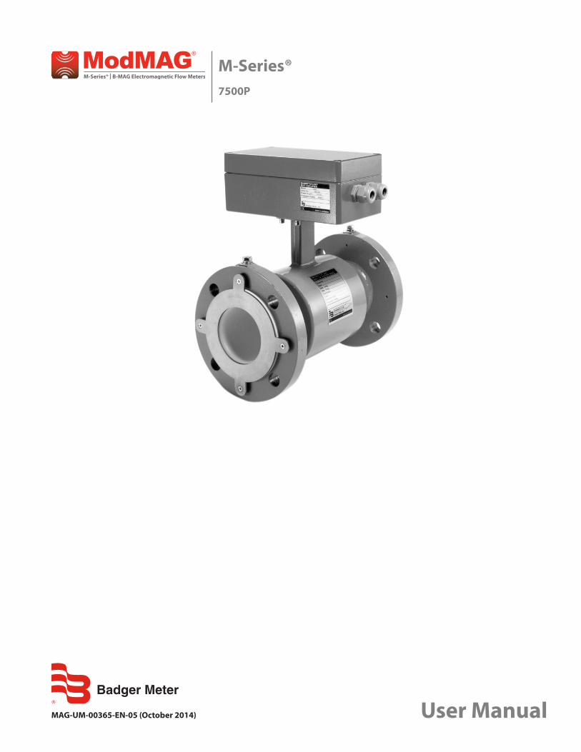
M-Series®7500P
MAG-UM-00365-EN-05 (October 2014) User Manual

CONTENTS
Scope of Manual . . . . . . . . . . . . . . . . . . . . . . . . . . . . . . . . . . . . . . . . . . . . . . . . . . . . . . . . . . . . . . . . . . . . . . 3
Operation . . . . . . . . . . . . . . . . . . . . . . . . . . . . . . . . . . . . . . . . . . . . . . . . . . . . . . . . . . . . . . . . . . . . . . . . . . 3
Product Unpacking and Inspection . . . . . . . . . . . . . . . . . . . . . . . . . . . . . . . . . . . . . . . . . . . . . . . . . . . . . . . . . . 3
Storage . . . . . . . . . . . . . . . . . . . . . . . . . . . . . . . . . . . . . . . . . . . . . . . . . . . . . . . . . . . . . . . . . . . . . . . . . 3
Meter Installation . . . . . . . . . . . . . . . . . . . . . . . . . . . . . . . . . . . . . . . . . . . . . . . . . . . . . . . . . . . . . . . . . . . . . 4
Piping Configuration . . . . . . . . . . . . . . . . . . . . . . . . . . . . . . . . . . . . . . . . . . . . . . . . . . . . . . . . . . . . . . . . 5
Temperature. . . . . . . . . . . . . . . . . . . . . . . . . . . . . . . . . . . . . . . . . . . . . . . . . . . . . . . . . . . . . . . . . . . . . . 5
Partially Full Pipe Situations . . . . . . . . . . . . . . . . . . . . . . . . . . . . . . . . . . . . . . . . . . . . . . . . . . . . . . . . . . . . 6
Grounding. . . . . . . . . . . . . . . . . . . . . . . . . . . . . . . . . . . . . . . . . . . . . . . . . . . . . . . . . . . . . . . . . . . . . . . . . . 7
Electrical Connections . . . . . . . . . . . . . . . . . . . . . . . . . . . . . . . . . . . . . . . . . . . . . . . . . . . . . . . . . . . . . . . . . . 8
Connecting to 110V AC from Batch Control Panel Power Supply. . . . . . . . . . . . . . . . . . . . . . . . . . . . . . . . . . . . . 8
Wiring to PC100 Controller . . . . . . . . . . . . . . . . . . . . . . . . . . . . . . . . . . . . . . . . . . . . . . . . . . . . . . . . . . . . 8
Wiring to ER-8 Totalizer/Rate Indicator . . . . . . . . . . . . . . . . . . . . . . . . . . . . . . . . . . . . . . . . . . . . . . . . . . . . . 9
Calibration. . . . . . . . . . . . . . . . . . . . . . . . . . . . . . . . . . . . . . . . . . . . . . . . . . . . . . . . . . . . . . . . . . . . . . . . . 10
Recalibration Procedure . . . . . . . . . . . . . . . . . . . . . . . . . . . . . . . . . . . . . . . . . . . . . . . . . . . . . . . . . . . . . 11
Pre-Selection Switches . . . . . . . . . . . . . . . . . . . . . . . . . . . . . . . . . . . . . . . . . . . . . . . . . . . . . . . . . . . . . . 12
Jumper Location . . . . . . . . . . . . . . . . . . . . . . . . . . . . . . . . . . . . . . . . . . . . . . . . . . . . . . . . . . . . . . . . . . 12
Specifications . . . . . . . . . . . . . . . . . . . . . . . . . . . . . . . . . . . . . . . . . . . . . . . . . . . . . . . . . . . . . . . . . . . . . . . 13
Dimensions . . . . . . . . . . . . . . . . . . . . . . . . . . . . . . . . . . . . . . . . . . . . . . . . . . . . . . . . . . . . . . . . . . . . . . . . 14
M-Series®, 7500P
Page 2 October 2014
SCOPE OF MANUALThis manual contains information concerning the installation, operation and maintenance of the M-Series 7500P flow meters. To ensure proper performance of the meters covered, the instructions given in this manual should be thoroughly understood. Retain the manual in a readily accessible location for future reference.
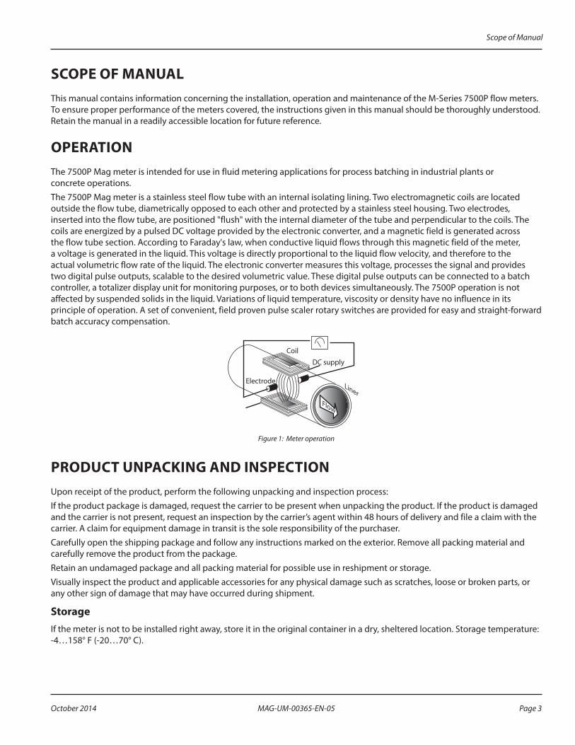
OPERATIONThe 7500P Mag meter is intended for use in fluid metering applications for process batching in industrial plants or concrete operations.The 7500P Mag meter is a stainless steel flow tube with an internal isolating lining. Two electromagnetic coils are located outside the flow tube, diametrically opposed to each other and protected by a stainless steel housing. Two electrodes, inserted into the flow tube, are positioned "flush" with the internal diameter of the tube and perpendicular to the coils. The coils are energized by a pulsed DC voltage provided by the electronic converter, and a magnetic field is generated across the flow tube section. According to Faraday's law, when conductive liquid flows through this magnetic field of the meter, a voltage is generated in the liquid. This voltage is directly proportional to the liquid flow velocity, and therefore to the actual volumetric flow rate of the liquid. The electronic converter measures this voltage, processes the signal and provides two digital pulse outputs, scalable to the desired volumetric value. These digital pulse outputs can be connected to a batch controller, a totalizer display unit for monitoring purposes, or to both devices simultaneously. The 7500P operation is not affected by suspended solids in the liquid. Variations of liquid temperature, viscosity or density have no influence in its principle of operation. A set of convenient, field proven pulse scaler rotary switches are provided for easy and straight-forward batch accuracy compensation.
Coil
DC supply
Electrode
Flow
Liner
Figure 1: Meter operation
PRODUCT UNPACKING AND INSPECTIONUpon receipt of the product, perform the following unpacking and inspection process:If the product package is damaged, request the carrier to be present when unpacking the product. If the product is damaged and the carrier is not present, request an inspection by the carrier’s agent within 48 hours of delivery and file a claim with the carrier. A claim for equipment damage in transit is the sole responsibility of the purchaser.Carefully open the shipping package and follow any instructions marked on the exterior. Remove all packing material and carefully remove the product from the package.Retain an undamaged package and all packing material for possible use in reshipment or storage.Visually inspect the product and applicable accessories for any physical damage such as scratches, loose or broken parts, or any other sign of damage that may have occurred during shipment.
StorageIf the meter is not to be installed right away, store it in the original container in a dry, sheltered location. Storage temperature: -4…158° F (-20…70° C).
Scope of Manual
Page 3 October 2014 MAG-UM-00365-EN-05
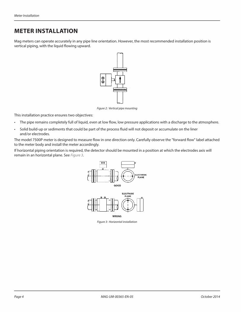
METER INSTALLATIONMag meters can operate accurately in any pipe line orientation. However, the most recommended installation position is vertical piping, with the liquid flowing upward.
Figure 2: Vertical pipe mounting
This installation practice ensures two objectives:
• The pipe remains completely full of liquid, even at low flow, low pressure applications with a discharge to the atmosphere.
• Solid build-up or sediments that could be part of the process fluid will not deposit or accumulate on the liner and/or electrodes.
The model 7500P meter is designed to measure flow in one direction only. Carefully observe the "forward flow" label attached to the meter body and install the meter accordingly.If horizontal piping orientation is required, the detector should be mounted in a position at which the electrodes axis will remain in an horizontal plane. See Figure 3.
Figure 3: Horizontal installation
Meter Installation
Page 4 October 2014MAG-UM-00365-EN-05

Piping ConfigurationAppropriate piping arrangements should be made to ensure the meter is not exposed to extreme pipe vibrations. The piping arrangements should include appropriate pipe supports.For optimum accuracy performance, sufficient inlet and outlet straight pipe runs are required. Three diameters of straight pipe are required on the inlet side of the meter, and two diameters are required on the outlet side, measured from the center of the meter body. See Figure 4 for additional requirements.Avoid installing the detector close to flow disturbance generating valves and fittings.Do not install the detector in the outlet side of piston or diaphragm type pumps. Avoid all pipe locations where the flow is pulsating. Avoid installing the detector in the suction side of any pumps; possible creation of a vacuum can affect the meter performance or cause damage to the PTFE liner.
(ANY POSITION)STRAIGHT PIPE RUN
PUMP
CHECK VALVE
NEEDLE VALVE
GLOBE VALVE
(FULLY OPENED) GATE VALVE
BALL VALVE
TEE
ELBOW
NO PUMPS
ANY VALVE
TEE
NO REQUIREMENT
PIPE REDUCERS
5-7 D
2 D3 D
ELBOW
UPSTREAM DOWN STREAM
Figure 4: Pipe diameters
Temperature
OTEE:N Environmental temperature of installation is not to exceed maximum specification of 122° F (50° C) for the meter. See "Specifications" on page 13 for full temperature specifications.
Meter Installation
Page 5 October 2014 MAG-UM-00365-EN-05
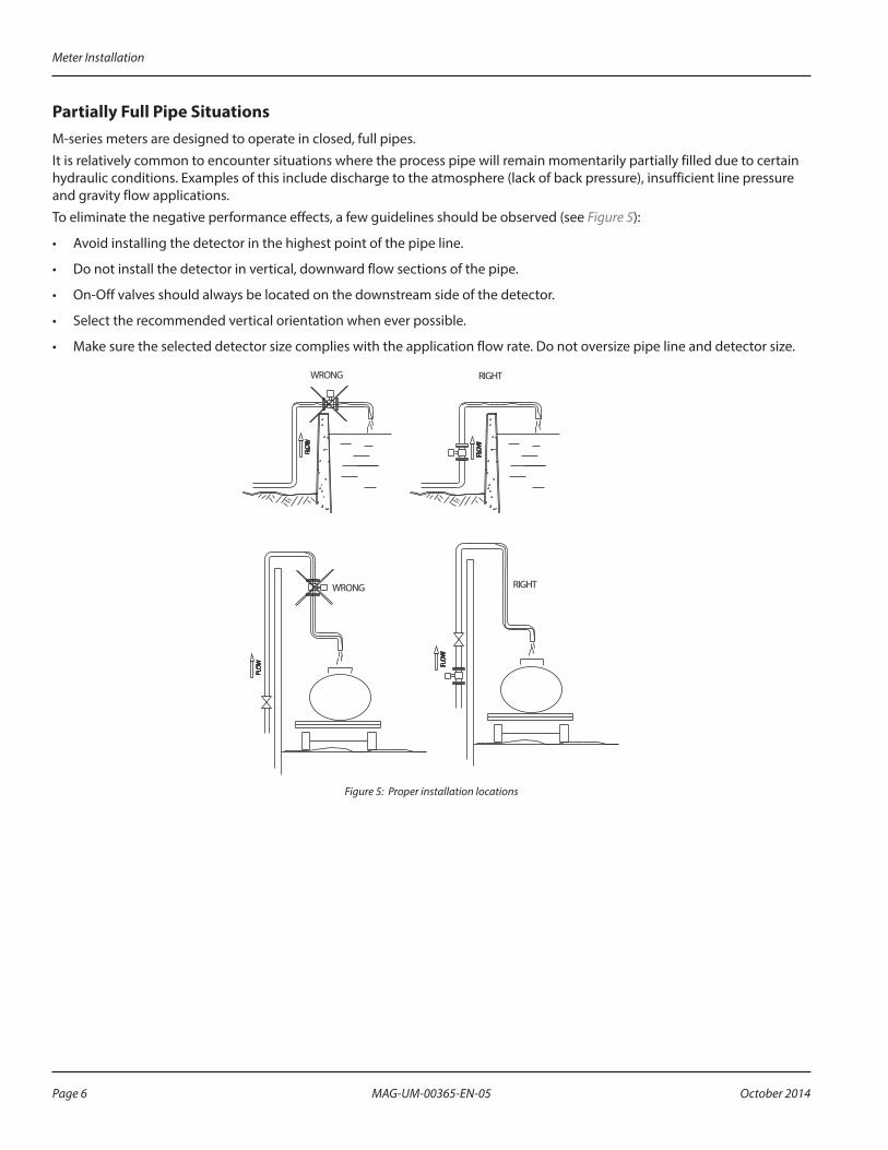
Partially Full Pipe SituationsM-series meters are designed to operate in closed, full pipes.It is relatively common to encounter situations where the process pipe will remain momentarily partially filled due to certain hydraulic conditions. Examples of this include discharge to the atmosphere (lack of back pressure), insufficient line pressure and gravity flow applications.To eliminate the negative performance effects, a few guidelines should be observed (see Figure 5):
• Avoid installing the detector in the highest point of the pipe line.
• Do not install the detector in vertical, downward flow sections of the pipe.
• On-Off valves should always be located on the downstream side of the detector.
• Select the recommended vertical orientation when ever possible.
• Make sure the selected detector size complies with the application flow rate. Do not oversize pipe line and detector size.
WRONG RIGHT
FLO
W
FLO
W
FLO
W
WRONG
FLO
W
RIGHT
Figure 5: Proper installation locations
Meter Installation
Page 6 October 2014MAG-UM-00365-EN-05

GROUNDINGProper grounding is vital to ensure a good mag meter operation. To ensure proper grounding, the 7500P mag meter is provided with a set of protective grounding rings. The rings also serve as protection for the liner. The main purpose of the ground connection is to provide electrical continuity between the liquid media, the amplifier’s input ground or zero voltage reference, and a good, solid earth ground. Connect a grounding strap to a solid, local earth ground (tower structure or pipe support) (see illustration). It is recommended to use copper wire, at least 12 AWG. When installing the meter, also use standard gaskets to avoid leaks.
Protective Grounding RingProtective Grounding Rings
Good LocalEarth Ground
Figure 6: Protective grounding rings
Grounding
Page 7 October 2014 MAG-UM-00365-EN-05
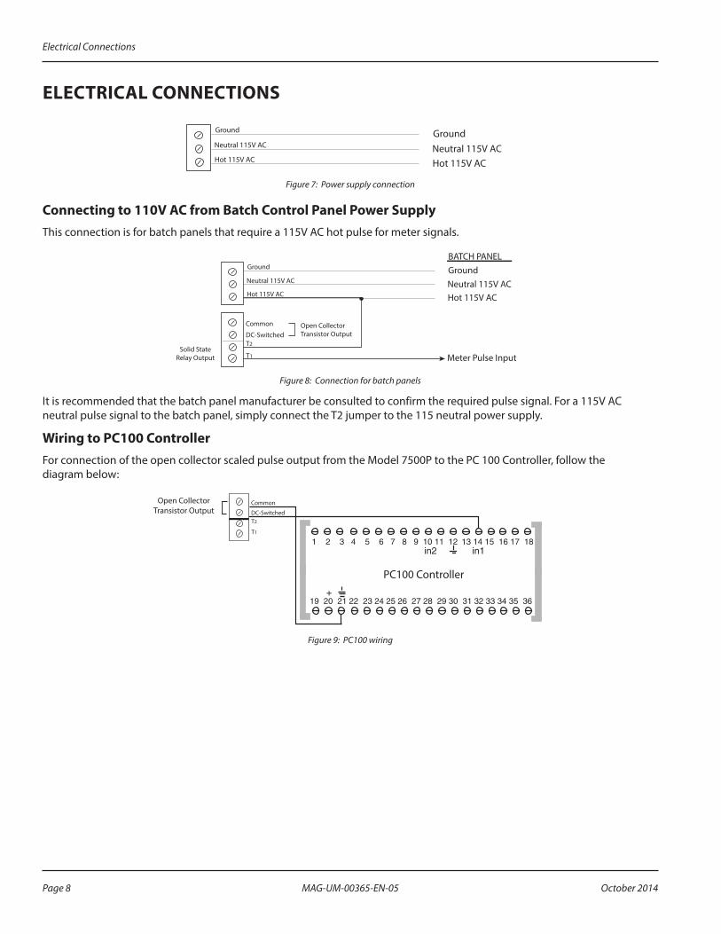
ELECTRICAL CONNECTIONS
GroundNeutral 115V AC Hot 115V AC
Ground
Neutral 115V AC
Hot 115V AC
Figure 7: Power supply connection
Connecting to 110V AC from Batch Control Panel Power SupplyThis connection is for batch panels that require a 115V AC hot pulse for meter signals.
T2
T1
BATCH PANELGroundNeutral 115V AC Hot 115V AC
Meter Pulse Input
DC-Switched
Common
Ground
Neutral 115V AC
Hot 115V AC
Open CollectorTransistor Output
Solid StateRelay Output
Figure 8: Connection for batch panels
It is recommended that the batch panel manufacturer be consulted to confirm the required pulse signal. For a 115V AC neutral pulse signal to the batch panel, simply connect the T2 jumper to the 115 neutral power supply.
Wiring to PC100 ControllerFor connection of the open collector scaled pulse output from the Model 7500P to the PC 100 Controller, follow the diagram below:
T2
T1
DC-Switched
Common
PC100 Controller
Open CollectorTransistor Output
Figure 9: PC100 wiring
Electrical Connections
Page 8 October 2014MAG-UM-00365-EN-05
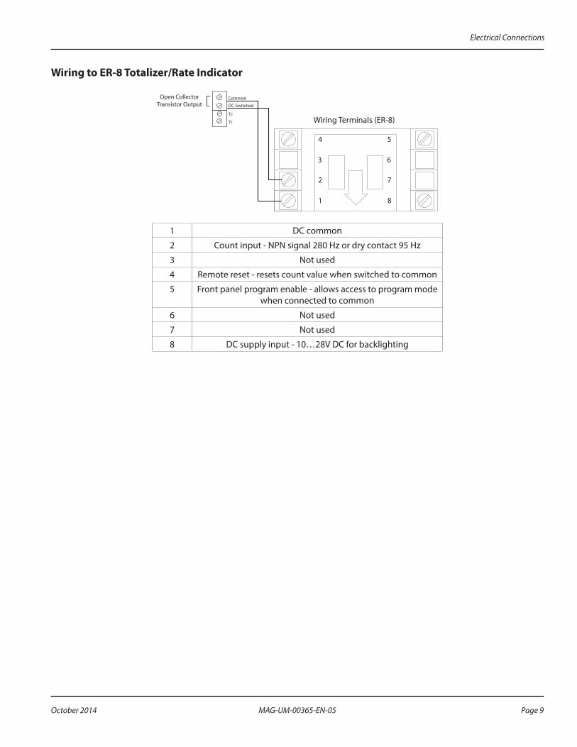
Wiring to ER-8 Totalizer/Rate Indicator
1
2
3
4 5
6
7
8
T2
T1
DC-Switched
CommonOpen CollectorTransistor Output
Wiring Terminals (ER-8)
1 DC common
2 Count input - NPN signal 280 Hz or dry contact 95 Hz
3 Not used
4 Remote reset - resets count value when switched to common
5 Front panel program enable - allows access to program mode when connected to common
6 Not used
7 Not used
8 DC supply input - 10…28V DC for backlighting
Electrical Connections
Page 9 October 2014 MAG-UM-00365-EN-05
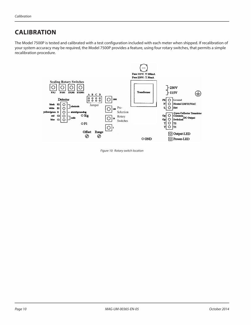
CALIBRATIONThe Model 7500P is tested and calibrated with a test configuration included with each meter when shipped. If recalibration of your system accuracy may be required, the Model 7500P provides a feature, using four rotary switches, that permits a simple recalibration procedure.
Figure 10: Rotary switch location
Calibration
Page 10 October 2014MAG-UM-00365-EN-05
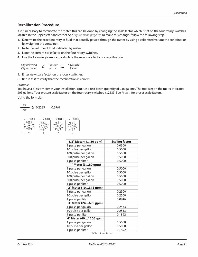
Recalibration ProcedureIf it is necessary to recalibrate the meter, this can be done by changing the scale factor which is set on the four rotary switches located in the upper left hand corner. See Figure 10 on page 10. To make this change, follow the following step.1. Determine the exact quantity of fluid that actually passed through the meter by using a calibrated volumetric container or
by weighing the container.2. Note the volume of fluid indicated by meter.3. Note the current scale factor on the four rotary switches.4. Use the following formula to calculate the new scale factor for recalibration:
Qty deliveredQty on meter
Old scale factor
New scale factorX
5. Enter new scale factor on the rotary switches.6. Rerun test to verify that the recalibration is correct.
Example:You have a 3" size meter in your installation. You run a test batch quantity of 238 gallons. The totalizer on the meter indicates 203 gallons. Your present scale factor on the four rotary switches is .2533. See Table 1 for preset scale factors.Using the formula:
X238203
0.2533 0.2969
0 1 2 3 4 5 6 7 8 9
0 1 2 3 4 5 6 7 8 9
0 1 2 3 4 5 6 7 8 9
0 1 2 3 4 5 6 7 8 9
x 0.1 x 0.01 x 0.001 x 0.0001
2 9 6 9.
.
1/2" Meter (1…30 gpm) Scaling factor1 pulse per gallon 0.050010 pulse per gallon 0.5000100 pulse per gallon 0.5000500 pulse per gallon 0.50001 pulse per liter 0.5000
1" Meter (3…80 gpm)1 pulse per gallon 0.500010 pulse per gallon 0.5000100 pulse per gallon 0.5000500 pulse per gallon 0.50001 pulse per liter 0.5000
2" Meter (10…315 gpm)1 pulse per gallon 0.250010 pulse per gallon 0.25001 pulse per liter 0.0946
3" Meter (24…690 gpm)1 pulse per gallon 0.253310 pulse per gallon 0.25331 pulse per liter 0.18924" Meter (40…1200 gpm)1 pulse per gallon 0.500010 pulse per gallon 0.50001 pulse per liter 0.1892
Table 1: Scale factors
Calibration
Page 11 October 2014 MAG-UM-00365-EN-05
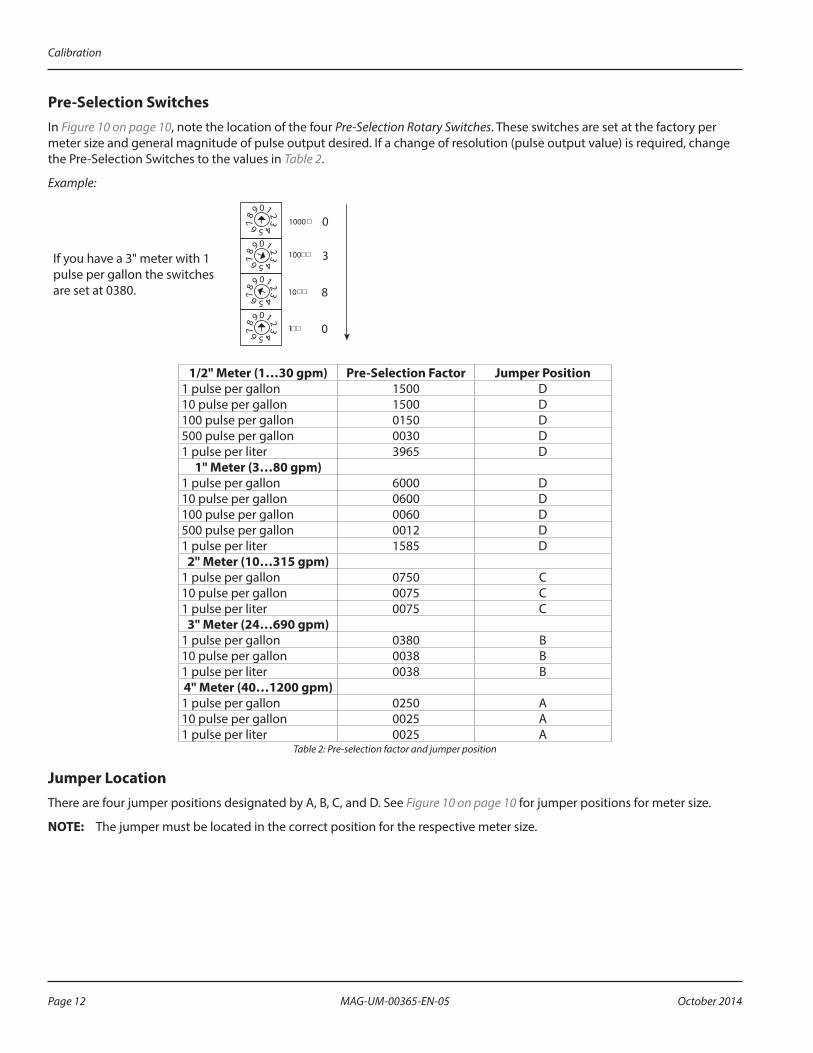
Pre-Selection SwitchesIn Figure 10 on page 10, note the location of the four Pre-Selection Rotary Switches. These switches are set at the factory per meter size and general magnitude of pulse output desired. If a change of resolution (pulse output value) is required, change the Pre-Selection Switches to the values in Table 2.
Example:
If you have a 3" meter with 1 pulse per gallon the switches are set at 0380.
0 1 2 3 4 5 6 7 8 9
0 1 2 3 4 5 6 7 8 9
0 1 2 3 4 5 6 7 8 9
0 1 2 3 4 5 6 7 8 9
1000
100
10
1
0
3
8
0
1/2" Meter (1…30 gpm) Pre-Selection Factor Jumper Position1 pulse per gallon 1500 D10 pulse per gallon 1500 D100 pulse per gallon 0150 D500 pulse per gallon 0030 D1 pulse per liter 3965 D
1" Meter (3…80 gpm)1 pulse per gallon 6000 D10 pulse per gallon 0600 D100 pulse per gallon 0060 D500 pulse per gallon 0012 D1 pulse per liter 1585 D
2" Meter (10…315 gpm)1 pulse per gallon 0750 C10 pulse per gallon 0075 C1 pulse per liter 0075 C
3" Meter (24…690 gpm)1 pulse per gallon 0380 B10 pulse per gallon 0038 B1 pulse per liter 0038 B4" Meter (40…1200 gpm)1 pulse per gallon 0250 A10 pulse per gallon 0025 A1 pulse per liter 0025 A
Table 2: Pre-selection factor and jumper position
Jumper LocationThere are four jumper positions designated by A, B, C, and D. See Figure 10 on page 10 for jumper positions for meter size.
OTEE:N The jumper must be located in the correct position for the respective meter size.
Calibration
Page 12 October 2014MAG-UM-00365-EN-05

SPECIFICATIONSDetector
Working Pressure 150 psi (10 bar)End Connections ANSI 150# carbon steel flangesFlow Tube Material AISI 316 stainless steelHousing and Flange Material Carbon steel, enamel paint finishingLiner Material PTFEElectrode Material Alloy CMaximum Liquid Temperature 212° F (100° C)
AmplifierPower Supply 110V AC ±10%, 5 VACoil Excitation Pulsed DC, 7.5 HzMinimum Liquid Conductivity 5 micromhos/cmMaximum Output Frequency 10 khzSystem Accuracy ±0.5% of rateRepeatability ±0.2%Enclosure Powder coated cast aluminum, NEMA 4Mounting Meter mounted onlyEnvironmental –4…122° F (–20…50° C)Output 1 Solid state relay up to 230V, 500 mAOutput 2 Opto-isolated open collector, 50 mA @ 24V DCFlow Direction UnidirectionalPulse Width 50% duty cycleCable Connections Two 1/2 in. NPT cord grip
Specifications
Page 13 October 2014 MAG-UM-00365-EN-05
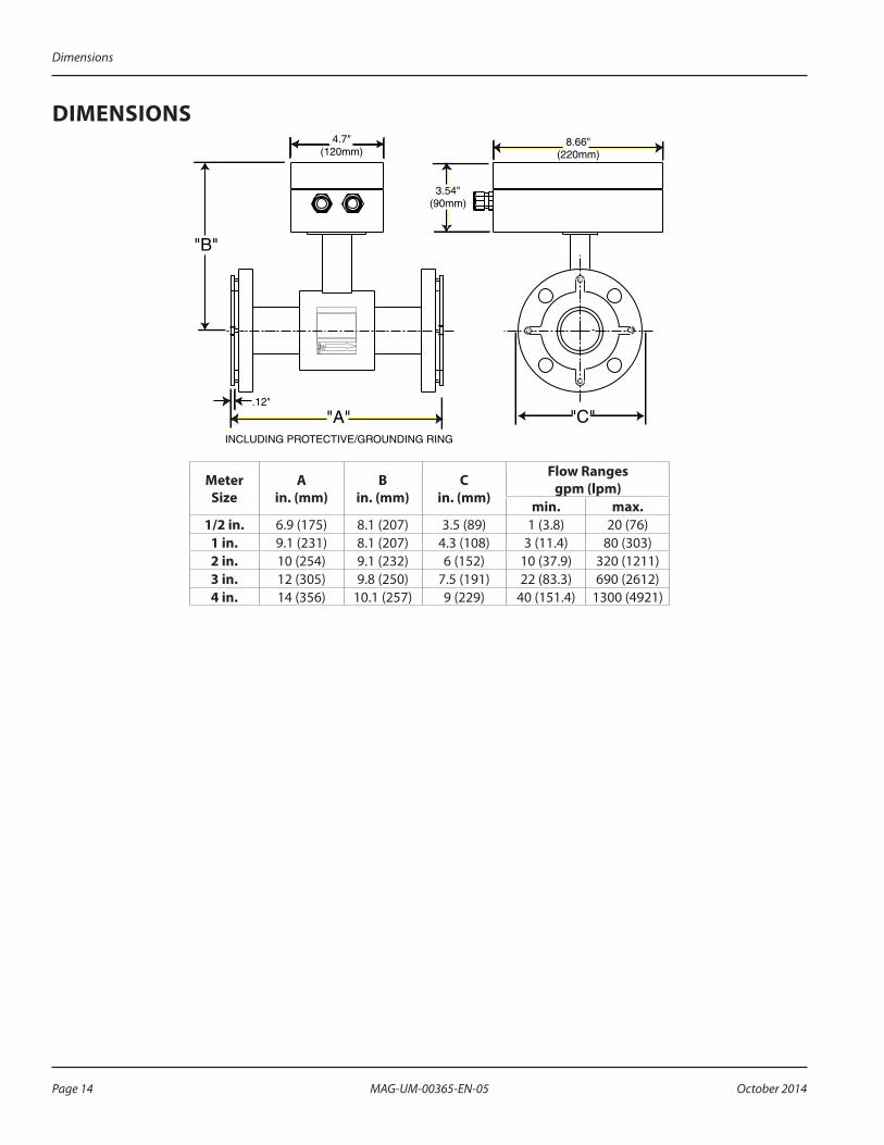
DIMENSIONS
"A" "C"
4.7"(120mm)
"B"
3.54"(90mm)
8.66"(220mm)
INCLUDING PROTECTIVE/GROUNDING RING
.12"
Meter Size
A in. (mm)
B in. (mm)
C in. (mm)
Flow Ranges gpm (lpm)
min. max.1/2 in. 6.9 (175) 8.1 (207) 3.5 (89) 1 (3.8) 20 (76)
1 in. 9.1 (231) 8.1 (207) 4.3 (108) 3 (11.4) 80 (303)2 in. 10 (254) 9.1 (232) 6 (152) 10 (37.9) 320 (1211)3 in. 12 (305) 9.8 (250) 7.5 (191) 22 (83.3) 690 (2612)4 in. 14 (356) 10.1 (257) 9 (229) 40 (151.4) 1300 (4921)
Dimensions
Page 14 October 2014MAG-UM-00365-EN-05

INTENTIONAL BLANK PAGE
Dimensions
Page 15 October 2014 MAG-UM-00365-EN-05

www.badgermeter.com
M-SERIES is registered trademark of Badger Meter, Inc. Other trademarks appearing in this document are the property of their respective entities. Due to continuous research, product improvements and enhancements, Badger Meter reserves the right to change product or system specifications without notice, except to the extent an outstanding contractual obligation exists. © 2014 Badger Meter, Inc. All rights reserved.
The Americas | Badger Meter | 4545 West Brown Deer Rd | PO Box 245036 | Milwaukee, WI 53224-9536 | 800-876-3837 | 414-355-0400México | Badger Meter de las Americas, S.A. de C.V. | Pedro Luis Ogazón N°32 | Esq. Angelina N°24 | Colonia Guadalupe Inn | CP 01050 | México, DF | México | +52-55-5662-0882Europe, Middle East and Africa | Badger Meter Europa GmbH | Nurtinger Str 76 | 72639 Neuffen | Germany | +49-7025-9208-0Europe, Middle East Branch Office | Badger Meter Europe | PO Box 341442 | Dubai Silicon Oasis, Head Quarter Building, Wing C, Office #C209 | Dubai / UAE | +971-4-371 2503 Czech Republic | Badger Meter Czech Republic s.r.o. | Maříkova 2082/26 | 621 00 Brno, Czech Republic | +420-5-41420411Slovakia | Badger Meter Slovakia s.r.o. | Racianska 109/B | 831 02 Bratislava, Slovakia | +421-2-44 63 83 01Asia Pacific | Badger Meter | 80 Marine Parade Rd | 21-06 Parkway Parade | Singapore 449269 | +65-63464836China | Badger Meter | 7-1202 | 99 Hangzhong Road | Minhang District | Shanghai | China 201101 | +86-21-5763 5412 Legacy Document: IOM-075-04 53400-075
Control. Manage. Optimize.