Embed Size (px)
Citation preview

User Manual
JVM-104 - HMI
60880106
We automate your success.

2 Jetter AG
Introduction
Variant: Jetter Design: O03 Item #: 60880106 Revision 4.01.3 December 2019 / Printed in Germany This document has been compiled by Jetter AG with due diligence, and based on the known state of the art. In the case of modifications, further developments or enhancements to products shipped in the past, a revised document will be supplied only if required by law, or deemed appropriate by Jetter AG. Jetter AG shall not be liable for errors in form or content, or for missing updates, as well as for damages or disadvantages resulting from such failure. The logos, brand names, and product names mentioned in this document are trademarks or registered trademarks of Jetter AG, of associated companies or other title owners and must not be used without consent of the respective title owner.
Jetter AG 3
JVM-104 Introduction
How to contact us:
Jetter AG
Graeterstrasse 2
D-71642 Ludwigsburg
Germany
Phone - Switchboard: +49 7141 2550-0
Phone - Sales: +49 7141 2550-433
Phone - Technical Hotline: +49 7141 2550-444
Fax - Sales: +49 7141 2550-484
E-mail - Sales: [email protected]
E-mail - Technical Hotline: [email protected]
Address

4 Jetter AG
Introduction
This document is an integral part of the JVM-104:
Keep this document in a way that it is always at hand until the JVM-104 will be disposed of.
Pass this document on if the JVM-104 is sold or loaned/leased out.
In any case you encounter difficulties to clearly understand the contents of this document, please contact Jetter AG. We would appreciate any suggestions and contributions on your part and would ask you to contact us at the following e-mail address: [email protected]. Your feedback will help us produce manuals that are more user-friendly, as well as address your wishes and requirements. This document contains important information on the following topics:
Transport Mounting Installation Programming Operation Maintenance Repair Therefore, you must carefully read, understand and observe this document, and especially the safety instructions. In the case of missing or inadequate knowledge of this document Jetter AG shall be exempted from any liability. Therefore, the operating company is recommended to obtain the persons' confirmation that they have read and understood this manual in writing.
Significance of this User Manual

Jetter AG 5
JVM-104 Contents
Table of Contents
1 Safety instructions 9
Basic safety instructions .............................................................................................................. 10
2 Product description and design 13
Product description ...................................................................................................................... 14 Parts and interfaces ..................................................................................................................... 16 Order reference ............................................................................................................................ 19 Physical dimensions .................................................................................................................... 20
3 Identifying the JVM-104 21
3.1 Identification by means of the nameplate ............................................................................... 22 Nameplate .................................................................................................................................... 23
3.2 Version registers ........................................................................................................................ 24 Software versions ......................................................................................................................... 25 Retrieving information from the device web site .......................................................................... 26
4 Mounting and installation of the JVM-104 29
4.1 Interfaces .................................................................................................................................... 30 Example - Wiring .......................................................................................................................... 31 Connecting the power supply ....................................................................................................... 32 Connecting the multi-purpose inputs ........................................................................................... 35 Connecting the multi-purpose outputs ......................................................................................... 38 CAN interfaces ............................................................................................................................. 42 Ethernet port ................................................................................................................................ 44 USB port ....................................................................................................................................... 45
4.2 Installing the JVM-104 ............................................................................................................... 46 Installation .................................................................................................................................... 47
4.3 IP configuration .......................................................................................................................... 52 Factory settings ............................................................................................................................ 53 The configuration memory ........................................................................................................... 54 Configuration registers ................................................................................................................. 55 Setting the IP address during runtime.......................................................................................... 56 Making settings on the device web site ....................................................................................... 57
5 Initial commissioning 59
5.1 Preparatory work and first insight into programming with JetSym STX ............................. 60 Preparatory work for initial commissioning .................................................................................. 61 Programming in the programming language JetSym STX .......................................................... 62
5.2 Configuring a project for the ER-STX-CE platform ................................................................ 63 Creating and configuring a visualization project in JetViewSoft .................................................. 64 Creating and configuring a visualization project in JetSym ......................................................... 69
5.3 ER-STX-CE platform - Programming ........................................................................................ 77 Entering data via digipot .............................................................................................................. 78 Using visualization commands to manipulate visualization objects ............................................. 82
6 Jetter AG
Contents
6 CANopen® STX API 85
STX function: CanOpenInit() ....................................................................................................... 87 STX function: CanOpenSetCommand() ...................................................................................... 89 STX function: CanOpenUploadSDO() ......................................................................................... 91 STX function: CanOpenDownloadSDO() .................................................................................... 96 STX function: CanOpenAddPDORx() ....................................................................................... 101 STX function: CanOpenAddPDOTx() ........................................................................................ 108 Heartbeat monitoring .................................................................................................................. 114 CANopen® object dictionary for JVM-104 ................................................................................. 118
7 SAE J1939 STX API 123
Content of a J1939 message .................................................................................................... 124 STX Function SAEJ1939Init() ................................................................................................... 126 STX function SAEJ1939SetSA() ............................................................................................... 127 STX function SAEJ1939GetSA() ............................................................................................... 128 STX function SAEJ1939AddRx() .............................................................................................. 129 STX function SAEJ1939AddTx() ............................................................................................... 132 STX function SAEJ1939RequestPGN() .................................................................................... 135 STX function SAEJ1939GetDM1() ............................................................................................ 138 STX function SAEJ1939GetDM2() ............................................................................................ 141 STX function SAEJ1939SetSPNConversion() .......................................................................... 144 STX Function SAEJ1939GetSPNConversion() ........................................................................ 145
8 File system 147
8.1 Directories ................................................................................................................................ 148 Directories ................................................................................................................................. 149
8.2 Properties ................................................................................................................................. 152 Flash disk - Properties ............................................................................................................... 153 USB flash drive - Properties ...................................................................................................... 154
9 FTP server 155
Logon......................................................................................................................................... 156 Example: Windows FTP client................................................................................................... 157
10 Programming 159
Abbreviations, module register properties and formats ............................................................ 160 10.1 Memories - Overview .............................................................................................................. 161
Operating system memory ........................................................................................................ 162 File system memory .................................................................................................................. 163 Application program memory .................................................................................................... 164 Memory for volatile application program variables .................................................................... 165 Memory for non-volatile application program registers ............................................................. 166 Memory for non-volatile application program variables ............................................................ 167 Special registers ........................................................................................................................ 169 Flags .......................................................................................................................................... 170
10.2 Controls and ignition .............................................................................................................. 172 Input keys .................................................................................................................................. 173 Digipot ....................................................................................................................................... 175 Ignition and shutdown delay ...................................................................................................... 177

Jetter AG 7
JVM-104 Contents
10.3 Multi-purpose inputs/outputs ................................................................................................. 179 Multi-purpose inputs - Status and commands ............................................................................ 180 Multi-purpose inputs - Analog functions ..................................................................................... 182 Multi-purpose inputs - Digital functions ...................................................................................... 185 Multi-purpose outputs - Status and commands ......................................................................... 188 Multi-purpose outputs - Analog functions ................................................................................... 190 Multi-purpose outputs - Digital functions .................................................................................... 192 Multi-purpose outputs PA3 and PA4 functioning as H-bridges .................................................. 194
10.4 Runtime registers .................................................................................................................... 196 Description of the runtime registers ........................................................................................... 197 Sample program - Runtime registers ......................................................................................... 199
10.5 Monitoring interface activities ................................................................................................ 201 Operating principle ..................................................................................................................... 202 Programming .............................................................................................................................. 204
10.6 User-programmable IP interface ............................................................................................ 206 10.6.1 Programming ............................................................................................................................ 208
Initializing the user-programmable IP interface ......................................................................... 209 Establishing a connection .......................................................................................................... 210 Sending data .............................................................................................................................. 214 Receiving data ........................................................................................................................... 216 Terminating a connection ........................................................................................................... 219
10.6.2 Registers ................................................................................................................................... 220 Register numbers ....................................................................................................................... 221 Register description ................................................................................................................... 222
10.6.3 Sample programs ..................................................................................................................... 225 Server ......................................................................................................................................... 226 Client .......................................................................................................................................... 230
11 Automatic copying of controller data 235
11.1 How it works ............................................................................................................................. 236 Loading the Autostart function ................................................................................................... 237 Executing the Autostart function ................................................................................................ 238 Terminating the Autostart mode ................................................................................................. 239
11.2 autostart.bat - Structure .......................................................................................................... 240 Available commands .................................................................................................................. 241 Example of a command file ........................................................................................................ 242
11.3 Data files ................................................................................................................................... 243 File format .................................................................................................................................. 244 Automatically loading data file information ................................................................................ 245
12 Operating system update 247
12.1 Updating the operating system of an HMI ............................................................................. 248 OS update by means of JetSym ................................................................................................ 249 Operating system update via FTP ............................................................................................. 250 Operating system update via USB ............................................................................................. 251 OS update via website of the device.......................................................................................... 254 Operating system update via \App ............................................................................................. 256
13 Application program 257
Application program - Default path ............................................................................................ 258 Loading an application program................................................................................................. 259

8 Jetter AG
Contents
14 Quick reference JVM-104 261
15 Quick reference of JVM-104 - Multi-purpose inputs/outputs 267
Appendix 269
A: Interfaces ................................................................................................................................. 270 Pinout - Overview ...................................................................................................................... 271
B: Technical data .......................................................................................................................... 275 Technical specifications ............................................................................................................. 276 Multi-purpose inputs/outputs - Technical specifications ............................................................ 278 Physical dimensions .................................................................................................................. 281 Operating parameters - Environment and mechanics .............................................................. 282 Operating parameters - EMC .................................................................................................... 283
C: Index ......................................................................................................................................... 284

Jetter AG 9
JVM-104 Safety instructions
1 Safety instructions
This chapter informs the user of basic safety instructions. It also warns the user of residual dangers, if there are any.
Topic Page Basic safety instructions ............................................................................... 10
Introduction
Contents
10 Jetter AG
1 Safety instructions
Basic safety instructions
This device complies with the valid safety regulations and standards. Jetter AG attaches great importance to the safety of the users. Of course, the user should adhere to the following regulations:
Relevant accident prevention regulations Accepted safety rules EC guidelines and other country-specific regulations
Usage according to the intended conditions of use implies operation in accordance with this User Manual. The device has been designed for use in commercial vehicles and mobile machines. The device JVM-104 is an HMI with integrated controller for exchange of data with peripheral devices. The HMI JVM-104 meets the requirements of the European Automotive EMC Directive for electric/electronic subassemblies. Operate the JVM-104 only within the limits set forth in the technical specifications. Because of its low operating voltage, the JVM-104 is classified as a SELV (Safety Extra-Low Voltage) system. Therefore, the HMI JVM-104 is not subject to the EU Low Voltage Directive.
The device must not be used in technical systems which to a high degree have to be fail-safe, such as, for example, in ropeways and airplanes. The JVM-104 is no safety-related part as per Machinery Directive 2006/42/EC. This device is not qualified for safety-relevant applications and must, therefore, NOT be used to protect persons. If you intend to operate the device at ambient conditions not being in conformity with the permitted operating conditions, please contact Jetter AG beforehand.
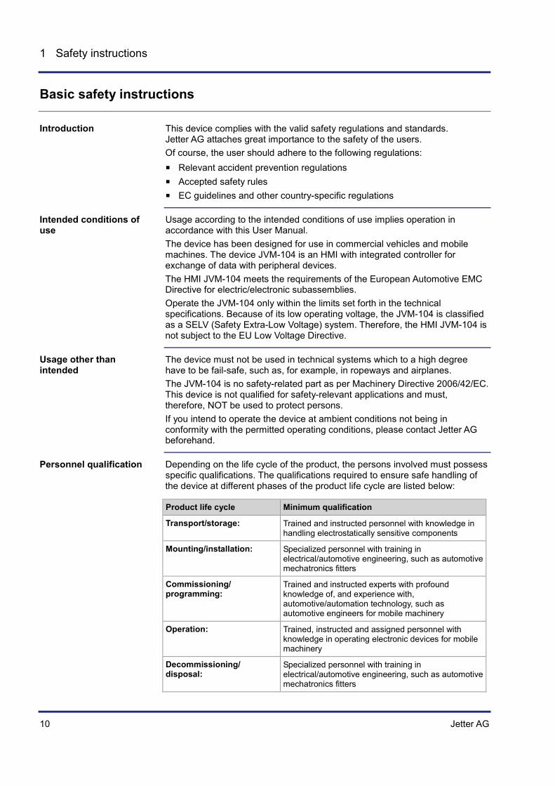
Depending on the life cycle of the product, the persons involved must possess specific qualifications. The qualifications required to ensure safe handling of the device at different phases of the product life cycle are listed below:
Product life cycle Minimum qualification
Transport/storage: Trained and instructed personnel with knowledge in handling electrostatically sensitive components
Mounting/installation: Specialized personnel with training in electrical/automotive engineering, such as automotive mechatronics fitters
Commissioning/ programming:
Trained and instructed experts with profound knowledge of, and experience with, automotive/automation technology, such as automotive engineers for mobile machinery
Operation: Trained, instructed and assigned personnel with knowledge in operating electronic devices for mobile machinery
Decommissioning/ disposal:
Specialized personnel with training in electrical/automotive engineering, such as automotive mechatronics fitters
Introduction
Intended conditions of use
Usage other than intended
Personnel qualification
Jetter AG 11
JVM-104 Safety instructions
For safety reasons, no modifications and changes to the device and its functions are permitted. Any modifications to the device not expressly authorized by Jetter AG will result in a loss of any liability claims to Jetter AG. The original parts are specifically designed for the device. Parts and equipment from other manufacturers have not been tested by Jetter AG and are, therefore, not released by Jetter AG. The installation of such parts may impair the safety and the proper functioning of the device. Any liability on the part of Jetter AG for any damages resulting from the use of non-original parts and equipment is excluded.
The JVM-104 contains electrostatically sensitive components which can be damaged if not handled properly. To exclude damages to the JVM-104 during transport it must be shipped in its original packaging or in packaging protecting against electrostatic discharge.
Use an appropriate outer packaging to protect the JVM-104 against impact or shock.
In case of damaged packaging inspect the device for any visible damage. Inform your freight forwarder and Jetter AG.
When storing the JVM-104 observe the environmental conditions given in the technical specification.
The operator is not allowed to repair the device. The device does not contain any parts that could be repaired by the operator. If the device needs repairing, please send it to Jetter AG.
When disposing of devices, the local environmental regulations must be complied with.
Modifications and alterations to the module
Transport
Storing
Repair and maintenance
Disposal


Jetter AG 13
JVM-104 Product description and design
2 Product description and design
This chapter covers the design of the device, as well as how the order reference is made up including all options.
Topic Page Product description ....................................................................................... 14 Parts and interfaces ...................................................................................... 16 Order reference ............................................................................................ 19 Physical dimensions ..................................................................................... 20
Introduction
Contents

14 Jetter AG
2 Product description and design
Product description
The JetView of the mobile automation series 104 is a compact full-graphics HMI. The HMI JVM-104 is extremely versatile thanks to its compact design and the integrated controller. The JVM-104 has especially been designed for use in the harsh environment of commercial vehicles and mobile machines. The HMI can be operated in all light conditions, due to the backlit keys and the light sensor, which automatically adapts the brightness of the display to the brightness of the surroundings.
The features of this product are listed below:
Display: 3.5" TFT, 350 cd/m2
Resolution: QVGA (320 x 240 pixels)
Touchscreen
4 function keys (lighted)
1 digipot with pushbutton function
Adjustable background lighting
Adjustable night-lighting Loudspeaker
Volume: 83 dB at a distance of 10 cm at resonance frequency of 2,670 Hz Adjustable frequency and volume.
Powerful programming language JetSym STX
Fast ARM11 CPU
Non-volatile registers 30,000
RAM: 128 MBytes
Flash memory: 512 MBytes
1 Ethernet port
2 CAN-2.0B interface
2 multi-purpose inputs, adjustable Digital input Voltage and current measuring Frequency measuring, counter function
2 multi-purpose inputs/outputs, configurable Digital input (active-low) Digital output up to 2.5 A PWM output H-bridge
1 USB port (2.0)
The HMI JVM-104
Product features

Jetter AG 15
JVM-104 Product description and design
The accessories are provided in the fastening kit. It includes a fastening bracket, a sealing ring and the corresponding screws and nuts.
Item no. Quantity Description
60880138 1 Fastening kit
The following items are included in the scope of delivery of the JVM-104:
Item no. Quantity Description
10001132 1 HMI JVM-104
60879283 1 Installation manual
Accessories
Scope of delivery

16 Jetter AG
2 Product description and design
Parts and interfaces
This chapter describes the parts and interfaces of the JVM-104.
The HMI JVM-104 provides a touchscreen of an active surface of 3.5". The illustration shows the front panel of the HMI with all its control elements.
67
1
34
5
2
Number Part Description
1 TFT display Active surface, touchscreen
2 Brightness sensor Senses the surrounding brightness
3 Input key UP Key with background lighting
4 Input key DOWN Key with background lighting
5 Digipot Rotary and pushbutton
6 Input key OK Key with background lighting
7 Input key ESC Key with background lighting
Introduction
Front panel of the JVM-104
Jetter AG 17
JVM-104 Product description and design
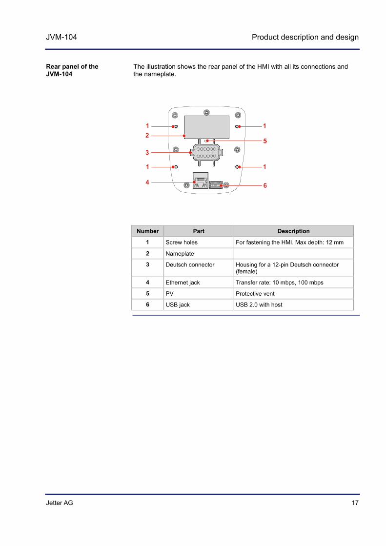
The illustration shows the rear panel of the HMI with all its connections and the nameplate.
1
6
1
11
2
3
4
Number Part Description
1 Screw holes For fastening the HMI. Max depth: 12 mm
2 Nameplate
3 Deutsch connector Housing for a 12-pin Deutsch connector (female)
4 Ethernet jack Transfer rate: 10 mbps, 100 mbps
5 PV Protective vent
6 USB jack USB 2.0 with host
Rear panel of the JVM-104

18 Jetter AG
2 Product description and design
The illustration below shows the status LEDs of the RJ45 jack:
21
Number Part Description
1 LED (amber) Blinks when active
2 LED (green) Lights up when connection has been established
LEDs on the bottom side

Jetter AG 19
JVM-104 Product description and design
Order reference
The HMI JVM-104 can be ordered from Jetter AG using the following item number:
Item no. Order reference
10001132 JVM-104-K00-O03
Order reference
20 Jetter AG
2 Product description and design
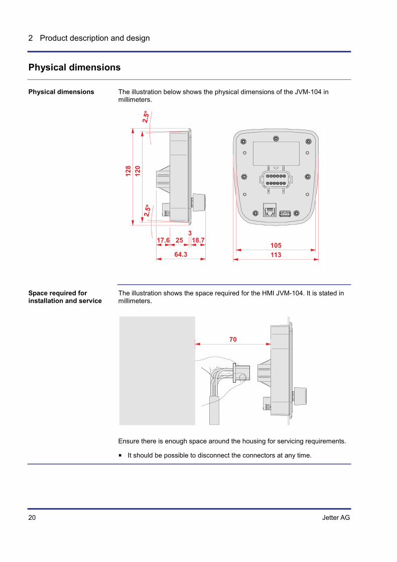
Physical dimensions
The illustration below shows the physical dimensions of the JVM-104 in millimeters.
113105
17.6 25 18.73
64.3
128
120
The illustration shows the space required for the HMI JVM-104. It is stated in millimeters.
70
Ensure there is enough space around the housing for servicing requirements.
It should be possible to disconnect the connectors at any time.
Physical dimensions
Space required for installation and service
Jetter AG 21
JVM-104 Identifying the JVM-104
3 Identifying the JVM-104
This chapter supports you in retrieving the following information about the JVM-104:
Hardware revision Electronic data sheet (EDS). Numerous manufacturing-related data are
stored to the EDS. Software versions
To be able to identify technical data about the HMI JVM-104 the following prerequisites must be fulfilled:
The HMI is connected to a PC. The programming tool JetSym 5.1.2 or higher is installed on the PC.
If you wish to contact the hotline of Jetter AG in case of a problem, please have the following information on the JVM-104 ready:
Serial number OS version of the HMI Hardware revision
Topic Page Identification by means of the nameplate ..................................................... 22 Version registers ........................................................................................... 24
Purpose of this chapter
Prerequisites
Information for hotline requests
Contents

22 Jetter AG
3 Identifying the JVM-104
3.1 Identification by means of the nameplate
Each HMI JVM-104 can be identified by its nameplate attached to its enclosure. If you wish to contact the hotline of Jetter AG in case of a problem, please have information on the hardware revision and serial number ready.
Topic Page Nameplate ..................................................................................................... 23
Introduction
Contents

Jetter AG 23
JVM-104 Identifying the JVM-104
Nameplate
The location of the nameplate on the rear panel of the JVM-104 is shown below.
The nameplate of a JVM-104 contains the following information:
Number Description
1 Product name
2 Serial number
3 Item number
4 Hardware revision
Position of the nameplate
Nameplate

24 Jetter AG
3 Identifying the JVM-104
3.2 Version registers
The operating system of the JVM-104 provides several registers which let you read out the version numbers of the OS and its components. If you wish to contact the hotline of Jetter AG in case of a problem, please have this information ready.
Topic Page Software versions ......................................................................................... 25 Retrieving information from the device web site ........................................... 26
Introduction
Contents

Jetter AG 25
JVM-104 Identifying the JVM-104
Software versions
The JVM-104 features software with unique version numbers which can be read out via special registers.
The software version number of the JVM-104 is a four-figure value.
1 . 2 . 3 . 4
Element Description
1 Major or main version number
2 Minor or secondary version number
3 Branch or intermediate version number
4 Build version number
A released version can be recognized by both Branch and Build having got value 0.
The following registers let you read out the software versions:
Register Description
200000 Operating system version
210001 Version of the STX interpreter for the STX application program (JetVM version)
The following screenshot shows a JetSym setup window displaying version registers. To have the version number displayed in the setup window of JetSym, select the format IP address.
Introduction
Format of software version numbers
Released version
Overview of registers
Version numbers in JetSym setup

26 Jetter AG
3 Identifying the JVM-104
Retrieving information from the device web site
The device web site in Internet Explorer shows all properties and version numbers of your device. It also lets you configure the Ethernet and the CANopen® interfaces.
To have the device web site displayed on your PC, enter the current IP address of the device in the Internet Explorer. Example:
To enter the IP address in the range of exceptions of the Internet Explorer, proceed as follows:
Step Action
1 Click menu item Tools and open the dialog Internet options.
2 Go to tab Connections and click the button LAN settings.
3 In section Proxy Server click the button Advanced.
The dialog Proxy Settings opens.
4 In the Exceptions pane of the dialog Proxy Settings, enter IP address 192.168.*, as is shown in the illustration below.
Introduction
Accessing the device web site
Prerequisites
Jetter AG 27
JVM-104 Identifying the JVM-104
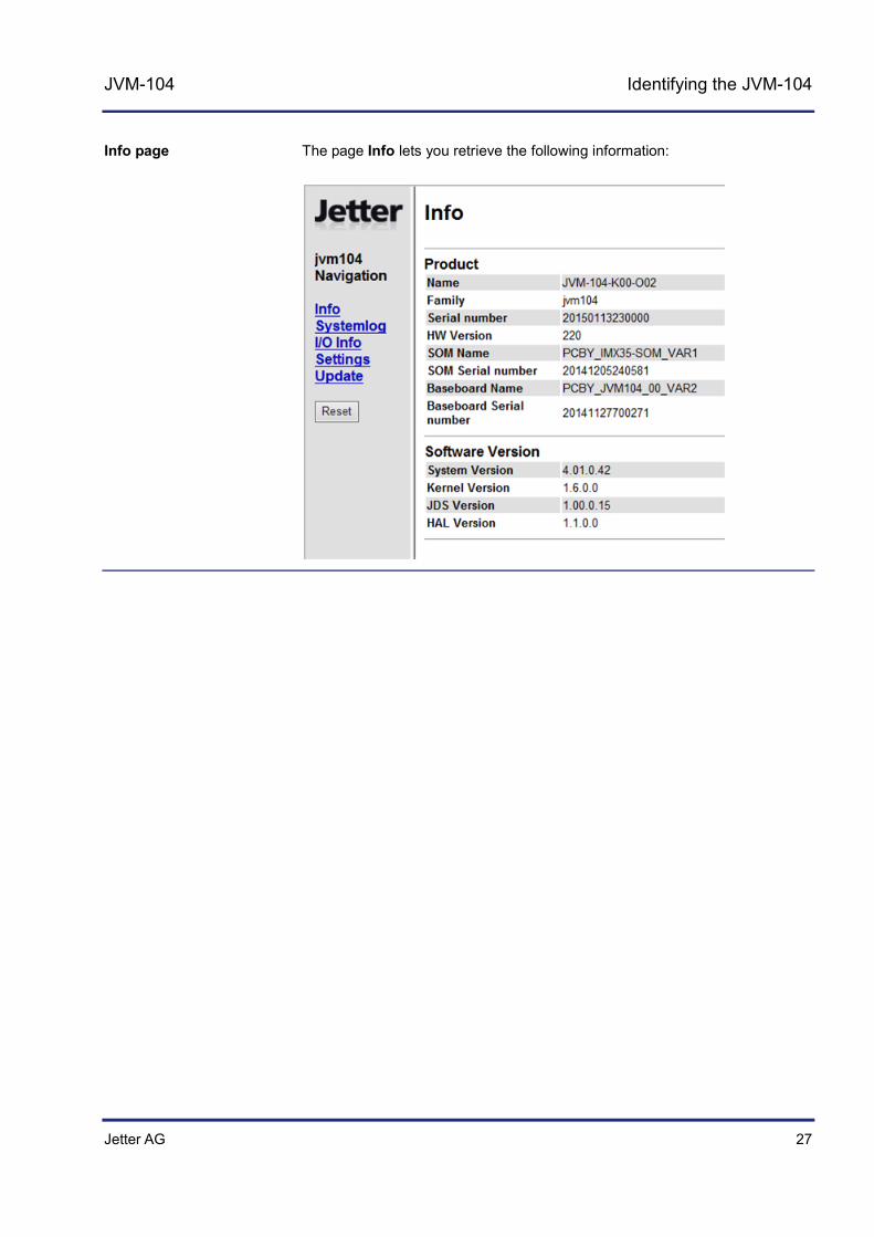
The page Info lets you retrieve the following information:
Info page


Jetter AG 29
JVM-104 Mounting and installation of the JVM-104
4 Mounting and installation of the JVM-104
This chapter describes the installation of the JVM-104 in the vehicle as regards the following points:
Planning the wiring of a JVM-104 Installation Configuration of the IP interface for the JVM-104
Topic Page Interfaces ...................................................................................................... 30 Installing the JVM-104 .................................................................................. 46 IP configuration ............................................................................................. 52
Purpose of this chapter
Contents

30 Jetter AG
4 Mounting and installation of the JVM-104
4.1 Interfaces
The HMI JVM-104 is equipped with the following interfaces:
DEUTSCH connector Ethernet port USB port
The DEUTSCH connector has the following functions:
Power supply of the JVM-104 Power supply for higher load currents Multi-purpose inputs Multi-purpose outputs CANopen® bus interfaces: CAN 1 and CAN 2 Recognition of the ignition
The function of the RJ45 jack is as follows:
Ethernet port to a PC Ethernet port to other devices, such as a controller
The USB port serves the following purposes:
Updating the system via USB flash drive Interface for USB flash drives providing additional memory Interface for USB devices, such as mouse or keyboard
Topic Page Example - Wiring ........................................................................................... 31 Connecting the power supply ....................................................................... 32 Connecting the multi-purpose inputs ............................................................ 35 Connecting the multi-purpose outputs .......................................................... 38 CAN interfaces .............................................................................................. 42 Ethernet port ................................................................................................. 44 USB port........................................................................................................ 45
Introduction
DEUTSCH connector
Ethernet port
USB port
Contents
Jetter AG 31
JVM-104 Mounting and installation of the JVM-104
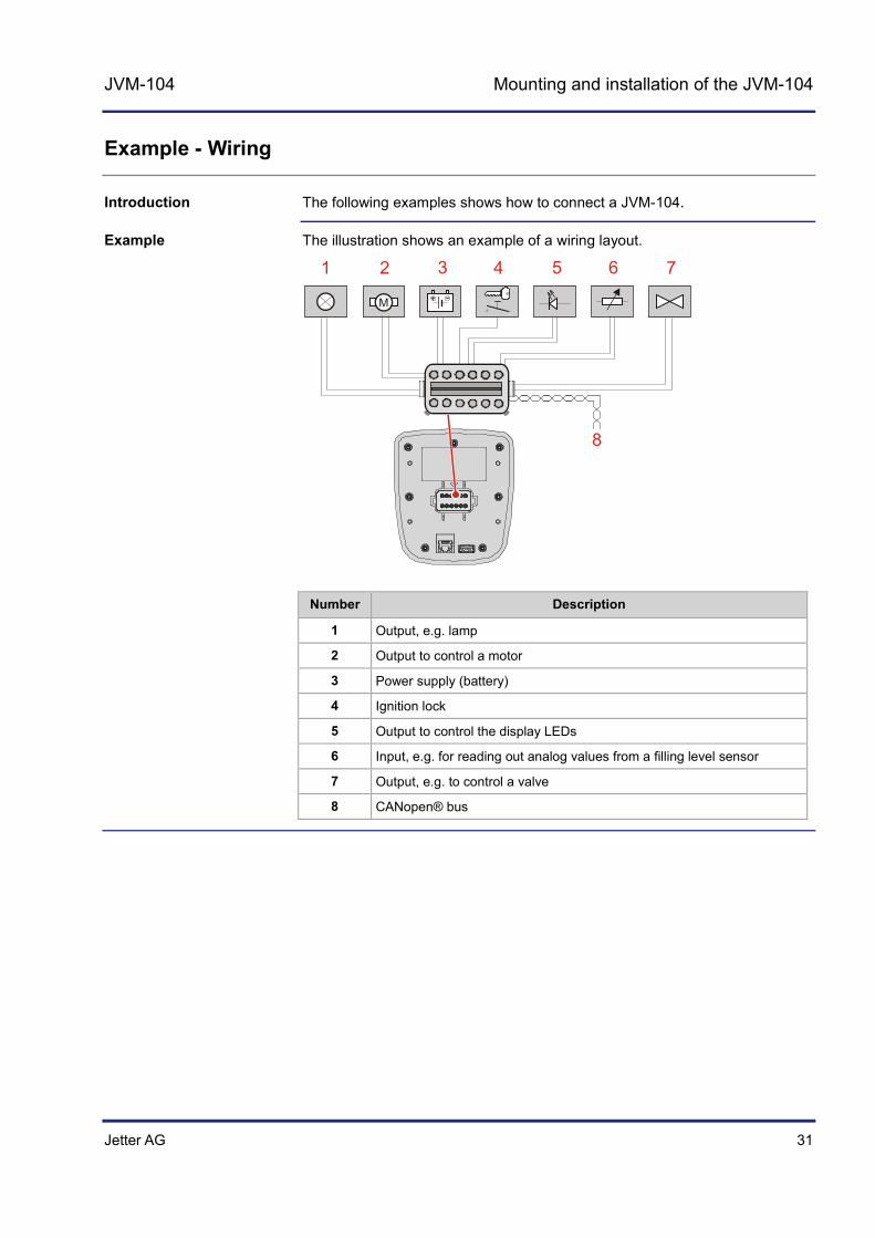
Example - Wiring
The following examples shows how to connect a JVM-104.
The illustration shows an example of a wiring layout.
M
1 2 3 4 5 6 7
8
Number Description
1 Output, e.g. lamp
2 Output to control a motor
3 Power supply (battery)
4 Ignition lock
5 Output to control the display LEDs
6 Input, e.g. for reading out analog values from a filling level sensor
7 Output, e.g. to control a valve
8 CANopen® bus
Introduction
Example

32 Jetter AG
4 Mounting and installation of the JVM-104
Connecting the power supply
This connector is also used for the following peripheral devices:
Power supply Multi-purpose inputs Multi-purpose outputs CAN communication Recognition of the ignition
The diagram shows the pinout of the power supply and ignition connector (viewing the cable side):
1 6
712
The pinout is as follows:
Pin Description Terminal number in vehicles
1 Reference potential (GND) Terminal # 31
6 Power supply UB for logic circuits Voltage: DC 12 V or DC 24 V Power consumption: 2 A max.
Terminal # 30
7 Power supply UB_PA for multi-purpose outputs of the HMI Voltage: DC 12 V or DC 24 V Power consumption: 10 A max.
Terminal # 30
8 Ignition (+) Terminal # 15
Purpose of the connector
Pinout of the power supply connector

Jetter AG 33
JVM-104 Mounting and installation of the JVM-104
Parameter Description
Rated voltage DC 12 V or DC 24 V
Permissible voltage range UB DC 8 V ... DC 32 V, to ISO 7637
Permissible voltage range - Ignition DC 5 V ... DC 32 V
Maximum current 2 A
Load dump protection DC 70 V max.
Typical current consumption logic circuit (UB)
170 mA at DC 12 V 90 mA at DC 24 V
Power consumption Approx. 2 W
Integrated protective functions Protection against polarity reversal, overloading, voltage surges
Parameter Description
Rated voltage DC 12 V or DC 24 V
Permissible voltage range UB_PA DC 8 V ... DC 32 V
Permissible voltage range - Ignition DC 5 V ... DC 32 V
Maximum current 10 A
Load dump protection DC 70 V max.
Integrated protective functions Protection against polarity reversal
Pin 7 of the DEUTSCH connector is configured for higher currents. Configure the wire size for pin 7 accordingly.
To start the JVM-104, pin 8 (ignition +) must be connected with pin 6. The ignition (+) control signal is issued when the key is in position Ignition ON.
When the JVM-104 is energized, the current consumption is temporarily higher. To guarantee reliable power-up of the JVM-104, supply at least three times as much power as would typically be needed.
Technical specifications - Power supply UB
Technical specifications - Voltage supply UB_PA
Important note on supply voltage
Note on ignition
Note on current consumption

34 Jetter AG
4 Mounting and installation of the JVM-104
Compatible mating parts for the 12-pin DEUTSCH connector are as follows:
Manufacturer DEUTSCH
Manufacturer item number - Housing
DT06-12S
Manufacturer item number - Wedgelock
W12S
Manufacturer item number - Crimp contact (receptacle)
0-462-201-16141
Wire size: 1.0 ... 1.5 mm2 (AWG 18 ... 16)
Mating parts

Jetter AG 35
JVM-104 Mounting and installation of the JVM-104
Connecting the multi-purpose inputs
The following functions are available:
Analog • Voltage measuring • Current measuring
Digital • Digital input • Frequency measurement • Counter function
The diagram shows the pinout of the connector for the multi-purpose inputs (viewing the cable side): Pin 1 for the reference potential is also color-coded.
1 6
712
The pinout is as follows:
Pin Description
1 Reference potential (GND)
11 Multi-purpose input MFQE1
12 Multi-purpose input MFQE2
Functions of the multi-purpose inputs
Pinout of the multi-purpose inputs
36 Jetter AG
4 Mounting and installation of the JVM-104
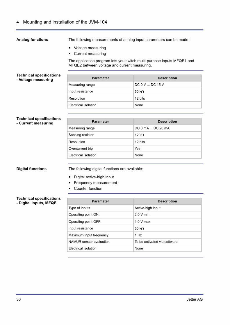
The following measurements of analog input parameters can be made:
Voltage measuring Current measuring
The application program lets you switch multi-purpose inputs MFQE1 and MFQE2 between voltage and current measuring.
Parameter Description
Measuring range DC 0 V ... DC 15 V
Input resistance 50 kΩ
Resolution 12 bits
Electrical isolation None
Parameter Description
Measuring range DC 0 mA ... DC 20 mA
Sensing resistor 120 Ω
Resolution 12 bits
Overcurrent trip Yes
Electrical isolation None
The following digital functions are available:
Digital active-high input Frequency measurement Counter function
Parameter Description
Type of inputs Active-high input
Operating point ON: 2.0 V min.
Operating point OFF: 1.0 V max.
Input resistance 50 kΩ
Maximum input frequency 1 Hz
NAMUR sensor evaluation To be activated via software
Electrical isolation None
Analog functions
Technical specifications - Voltage measuring
Technical specifications - Current measuring
Digital functions
Technical specifications - Digital inputs, MFQE
Jetter AG 37
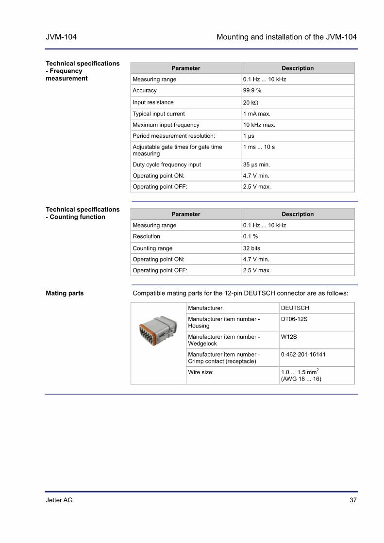
JVM-104 Mounting and installation of the JVM-104
Parameter Description
Measuring range 0.1 Hz ... 10 kHz
Accuracy 99.9 %
Input resistance 20 kΩ
Typical input current 1 mA max.
Maximum input frequency 10 kHz max.
Period measurement resolution: 1 µs
Adjustable gate times for gate time measuring
1 ms ... 10 s
Duty cycle frequency input 35 µs min.
Operating point ON: 4.7 V min.
Operating point OFF: 2.5 V max.
Parameter Description
Measuring range 0.1 Hz ... 10 kHz
Resolution 0.1 %
Counting range 32 bits
Operating point ON: 4.7 V min.
Operating point OFF: 2.5 V max.
Compatible mating parts for the 12-pin DEUTSCH connector are as follows:
Manufacturer DEUTSCH
Manufacturer item number - Housing
DT06-12S
Manufacturer item number - Wedgelock
W12S
Manufacturer item number - Crimp contact (receptacle)
0-462-201-16141
Wire size: 1.0 ... 1.5 mm2 (AWG 18 ... 16)
Technical specifications - Frequency measurement
Technical specifications - Counting function
Mating parts
38 Jetter AG
4 Mounting and installation of the JVM-104
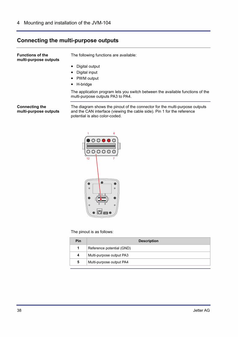
Connecting the multi-purpose outputs
The following functions are available:
Digital output Digital input PWM output H-bridge
The application program lets you switch between the available functions of the multi-purpose outputs PA3 to PA4.
The diagram shows the pinout of the connector for the multi-purpose outputs and the CAN interface (viewing the cable side). Pin 1 for the reference potential is also color-coded.
1 6
712
The pinout is as follows:
Pin Description
1 Reference potential (GND)
4 Multi-purpose output PA3
5 Multi-purpose output PA4
Functions of the multi-purpose outputs
Connecting the multi-purpose outputs
Jetter AG 39
JVM-104 Mounting and installation of the JVM-104
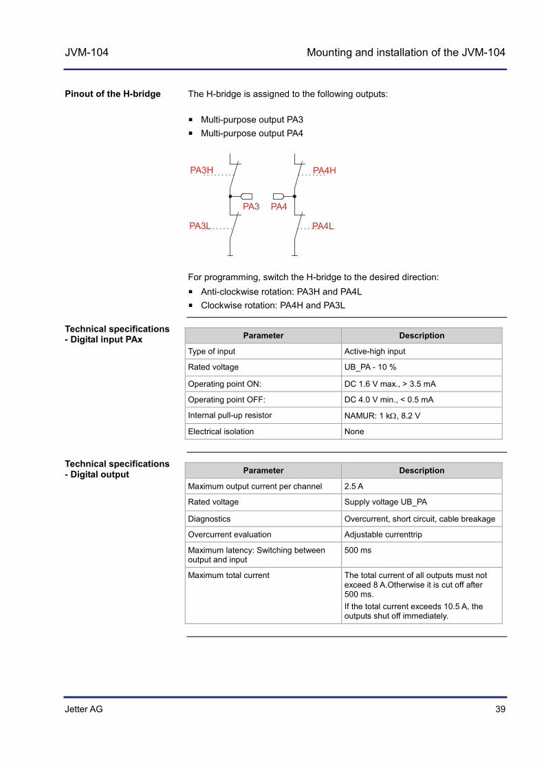
The H-bridge is assigned to the following outputs:
Multi-purpose output PA3 Multi-purpose output PA4
PA3H
PA3L
PA4H
PA4L
PA3 PA4
For programming, switch the H-bridge to the desired direction:
Anti-clockwise rotation: PA3H and PA4L Clockwise rotation: PA4H and PA3L
Parameter Description
Type of input Active-high input
Rated voltage UB_PA - 10 %
Operating point ON: DC 1.6 V max., > 3.5 mA
Operating point OFF: DC 4.0 V min., < 0.5 mA
Internal pull-up resistor NAMUR: 1 kΩ, 8.2 V
Electrical isolation None
Parameter Description
Maximum output current per channel 2.5 A
Rated voltage Supply voltage UB_PA
Diagnostics Overcurrent, short circuit, cable breakage
Overcurrent evaluation Adjustable currenttrip
Maximum latency: Switching between output and input
500 ms
Maximum total current The total current of all outputs must not exceed 8 A.Otherwise it is cut off after 500 ms. If the total current exceeds 10.5 A, the outputs shut off immediately.
Pinout of the H-bridge
Technical specifications - Digital input PAx
Technical specifications - Digital output
40 Jetter AG
4 Mounting and installation of the JVM-104
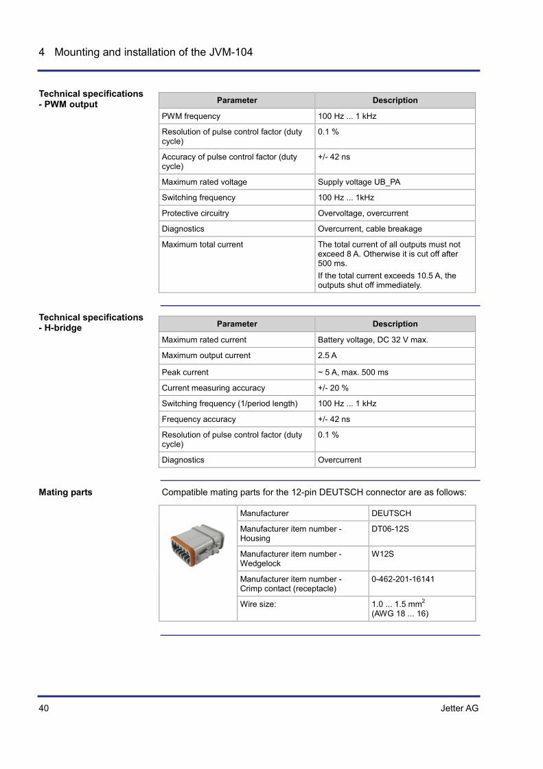
Parameter Description
PWM frequency 100 Hz ... 1 kHz
Resolution of pulse control factor (duty cycle)
0.1 %
Accuracy of pulse control factor (duty cycle)
+/- 42 ns
Maximum rated voltage Supply voltage UB_PA
Switching frequency 100 Hz ... 1kHz
Protective circuitry Overvoltage, overcurrent
Diagnostics Overcurrent, cable breakage
Maximum total current The total current of all outputs must not exceed 8 A. Otherwise it is cut off after 500 ms. If the total current exceeds 10.5 A, the outputs shut off immediately.
Parameter Description
Maximum rated current Battery voltage, DC 32 V max.
Maximum output current 2.5 A
Peak current ~ 5 A, max. 500 ms
Current measuring accuracy +/- 20 %
Switching frequency (1/period length) 100 Hz ... 1 kHz
Frequency accuracy +/- 42 ns
Resolution of pulse control factor (duty cycle)
0.1 %
Diagnostics Overcurrent
Compatible mating parts for the 12-pin DEUTSCH connector are as follows:
Manufacturer DEUTSCH
Manufacturer item number - Housing
DT06-12S
Manufacturer item number - Wedgelock
W12S
Manufacturer item number - Crimp contact (receptacle)
0-462-201-16141
Wire size: 1.0 ... 1.5 mm2 (AWG 18 ... 16)
Technical specifications - PWM output
Technical specifications - H-bridge
Mating parts

Jetter AG 41
JVM-104 Mounting and installation of the JVM-104
Multi-purpose outputs PA3 and PA4 functioning as H-bridges
(see page 194)
Related topics
42 Jetter AG
4 Mounting and installation of the JVM-104
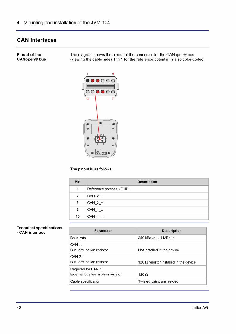
CAN interfaces
The diagram shows the pinout of the connector for the CANopen® bus (viewing the cable side): Pin 1 for the reference potential is also color-coded.
1 6
712
The pinout is as follows:
Pin Description
1 Reference potential (GND)
2 CAN_2_L
3 CAN_2_H
9 CAN_1_L
10 CAN_1_H
Parameter Description
Baud rate 250 kBaud ... 1 MBaud
CAN 1: Bus termination resistor
Not installed in the device
CAN 2: Bus termination resistor
120 Ω resistor installed in the device
Required for CAN 1: External bus termination resistor
120 Ω
Cable specification Twisted pairs, unshielded
Pinout of the CANopen® bus
Technical specifications - CAN interface

Jetter AG 43
JVM-104 Mounting and installation of the JVM-104
The JVM-104 has not got an integrated bus terminating resistor.
The CAN_L and CAN_H cable pairs must be twisted.
Parameter Description
Core cross-sectional area 1000 kBaud: 0.25 … 0.34 mm2 500 kBaud: 0.34 … 0.50 mm2 250 kBaud: 0.34 … 0.60 mm2
Cable capacitance 60 pF/m max.
Resistivity 1000 kBaud: 70 Ω/km max. 500 kBaud: 60 Ω/km max. 250 kBaud: 60 Ω/km max.
Number of cores 2
Twisting CAN_L and CAN_H cables are twisted pairwise
The maximum permitted cable length depends on the baud rate used and the number of CANopen® devices connected.
Baud rate Cable length Stub length Total stub length
1000 kBaud 25 m max. 0.3 m max. 1.5 m
500 kBaud 100 m max. 5 m max. 30 m
250 kBaud 250 m max. 10 m max. 60 m
Compatible mating parts for the 12-pin DEUTSCH connector are as follows:
Manufacturer DEUTSCH
Manufacturer item number - Housing
DT06-12S
Manufacturer item number - Wedgelock
W12S
Manufacturer item number - Crimp contact (receptacle)
0-462-201-16141
Wire size: 1.0 ... 1.5 mm2 (AWG 18 ... 16)
Bus terminating resistor
Twisting
Specification - CAN bus cable
Cable lengths
Mating parts

44 Jetter AG
4 Mounting and installation of the JVM-104
Ethernet port
The diagram below shows the pin assignment of the connector jack for the Ethernet cable:
Parameter Description
Type of terminal RJ45 Ethernet jack
Number of ports 1
Bit rate 10 Mbit/s, 100 Mbit/s
Auto-crossover Yes
For connecting devices to the Ethernet interface, you can order the following cables separately from Jetter AG :
Item no. Item
60537500 Patch cable 1:1, 1 m gray Hirose, Cat 5e, shielded
60854512 Patch cable 1:1, 2 m gray Hirose, Cat 5e, shielded
60854514 Patch cable 1:1, 5 m gray Hirose, Cat 5e, shielded
60854515 Patch cable 1:1, 10 m gray Hirose, Cat 5e, shielded
Pin assignment of the Ethernet port
Technical specifications - Ethernet
Ethernet cables

Jetter AG 45
JVM-104 Mounting and installation of the JVM-104
USB port
The USB port supports the following functions:
Connecting input devices such as mouse or keyboard Storing to and loading data from a USB flash drive Updating the operating system
The illustration shows the USB port:
Parameter Description
Power supply 5 V, 500 mA max.
USB port USB host interface, USB 2.0
Short-circuit capability Yes Transient short-circuit current: ~ 0.8 A
Functions of the USB port
USB port
Technical specifications - USB flash drive

46 Jetter AG
4 Mounting and installation of the JVM-104
4.2 Installing the JVM-104
This chapter describes how to install the JVM-104.
Topic Page Installation ..................................................................................................... 47
Introduction
Contents

Jetter AG 47
JVM-104 Mounting and installation of the JVM-104
Installation
This chapter describes how the HMI JVM-104 is to be installed.
Select a suitable place for the device to be installed. The place where the device is to be installed must meet the following requirements:
The installation surface must be level. The installation surface should be no more than 5 mm thick. The installation location must allow air to circulate. The installation location must be accessible for servicing. The installation location must be of sufficient size.
Do not install the device in locations that do not meet the a.m. requirements. The following installation locations are unsuitable for mounting the HMI:
Unsuitable installation location
Reason
Outdoor installation The HMI must not be exposed to rain or a jet of water. Therefore, do not use a steam jet or other such devices to clean the HMI.
Unventilated installation location
The HMI could overheat as heat builds up.
Installation location close to heat-sensitive materials
The materials could become warped or misshapen as a result of heat produced by the HMI.
Uneven installation surfaces The installation surface could become misshapen when fitting the HMI. Fastening is unstable and precarious.
Consider ergonomic principles. Select a user-friendly place for installation:
The controls must be easy to reach. The HMI screen must be easy to read. Avoid installation locations that are unsuitable from an ergonomic point of view:
Extreme angles, which could make it difficult to see the HMI Unsuitable lighting conditions with reflection and glare Concealed installation locations that are difficult for the user to access
The accessories are provided in the fastening kit. It includes a fastening bracket, a sealing ring and the corresponding screws and nuts.
Item no. Quantity Description
60880138 1 Fastening kit
Introduction
Selecting a place for installation
Avoiding unsuitable installation locations
Ergonomic principles
Accessories
48 Jetter AG
4 Mounting and installation of the JVM-104
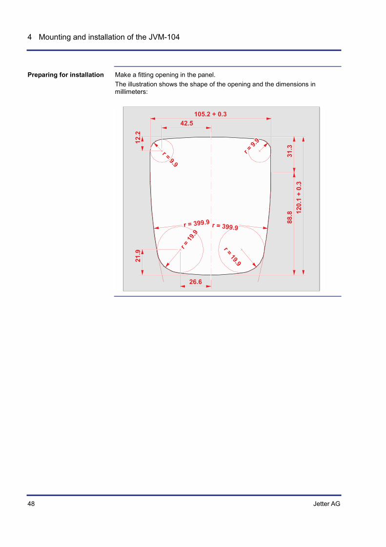
Make a fitting opening in the panel. The illustration shows the shape of the opening and the dimensions in millimeters:
42.5105.2 + 0.3
26.631
.388
.8 120.
1 +
0.3
21.9
12.2
r = 9.
9r = 9.9
r = 19.9
r = 19
.9
r = 399.9r = 399.9
Preparing for installation
Jetter AG 49
JVM-104 Mounting and installation of the JVM-104
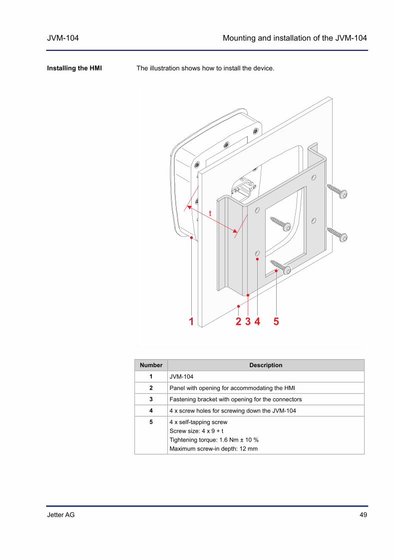
The illustration shows how to install the device.
54321
Number Description
1 JVM-104
2 Panel with opening for accommodating the HMI
3 Fastening bracket with opening for the connectors
4 4 x screw holes for screwing down the JVM-104
5 4 x self-tapping screw Screw size: 4 x 9 + t Tightening torque: 1.6 Nm ± 10 % Maximum screw-in depth: 12 mm
Installing the HMI

50 Jetter AG
4 Mounting and installation of the JVM-104
Step Action
1 Insert the HMI into the front of the opening in the panel.
2 Hold the fastening bracket against the panel from the rear. To this end, the connectors must be seen through the opening of the fastening bracket.
3 Screw the HMI, together with the fastening bracket, onto the panel. The stud torque should be 1.6 Nm ± 10 %.
The illustration shows the installed HMI JVM-104.

Jetter AG 51
JVM-104 Mounting and installation of the JVM-104
Install strain reliefs for the connecting cables. Take care to leave enough space for the connectors. Connectors must not be obstructed, so that they can be removed in the event of a service requirement.
Installing the strain relief
52 Jetter AG
4 Mounting and installation of the JVM-104
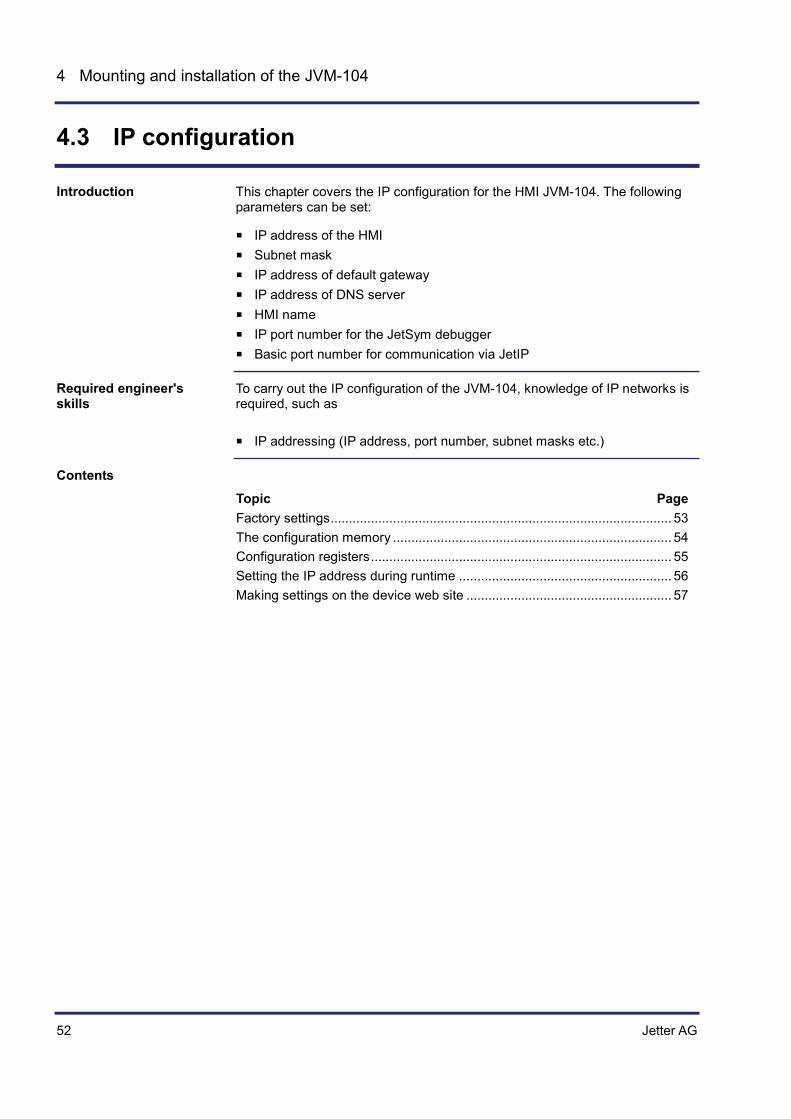
4.3 IP configuration
This chapter covers the IP configuration for the HMI JVM-104. The following parameters can be set:
IP address of the HMI Subnet mask IP address of default gateway IP address of DNS server HMI name IP port number for the JetSym debugger Basic port number for communication via JetIP
To carry out the IP configuration of the JVM-104, knowledge of IP networks is required, such as
IP addressing (IP address, port number, subnet masks etc.)
Topic Page Factory settings ............................................................................................. 53 The configuration memory ............................................................................ 54 Configuration registers .................................................................................. 55 Setting the IP address during runtime .......................................................... 56 Making settings on the device web site ........................................................ 57
Introduction
Required engineer's skills
Contents
Jetter AG 53
JVM-104 Mounting and installation of the JVM-104
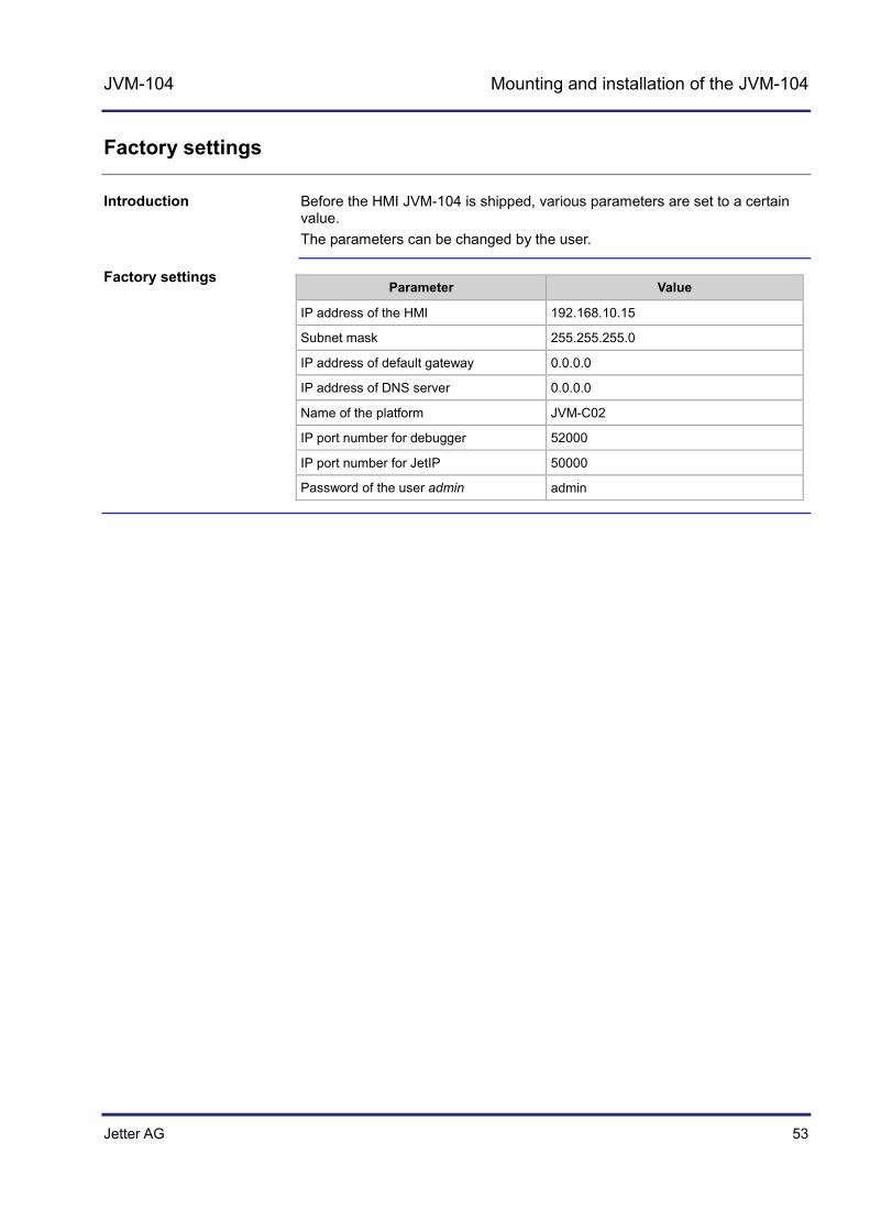
Factory settings
Before the HMI JVM-104 is shipped, various parameters are set to a certain value. The parameters can be changed by the user.
Parameter Value
IP address of the HMI 192.168.10.15
Subnet mask 255.255.255.0
IP address of default gateway 0.0.0.0
IP address of DNS server 0.0.0.0
Name of the platform JVM-C02
IP port number for debugger 52000
IP port number for JetIP 50000
Password of the user admin admin
Introduction
Factory settings

54 Jetter AG
4 Mounting and installation of the JVM-104
The configuration memory
The HMI retrieves the parameters for initializing the IP interface from the configuration memory during the boot process. The user can access the data stored in the configuration memory in the following ways:
The web interface lets you read out data and make changes to them. Registers let you read out data and make changes to them.
The HMI reads data located in the configuration memory only during the boot process. If you make changes to the configuration memory, reboot the HMI for these changes to take effect. Only this way these changes take effect. If you change the IP address during runtime, this modification immediately takes effect. However, changes made during runtime are not remanent.
Before the HMI uses data from the configuration memory, it checks them for plausibility. If entries are invalid or absent, the HMI uses the following default values:
Parameter Default value
IP address of the controller 192.168.10.15
Subnet mask 255.255.255.0
IP address of default gateway 0.0.0.0
IP address of DNS server 0.0.0.0
Name of the platform JVM-C02
Suffix type of the name 0
IP port number for debugger 52000
IP port number for JetIP 50000
Configuration registers (see page 55)
Introduction
Enabling conditions
Default values
Related topics

Jetter AG 55
JVM-104 Mounting and installation of the JVM-104
Configuration registers
Configuration registers grant you read or write access to the parameters of the IP configuration. A range of registers holds the data contained in the configuration memory. Another range contains the parameters used for initializing the IP interface.
The register number is calculated by adding the number of the module register (MR) to the number of the basic register.
HMI Data range Type of access
Basic register number
Register numbers
JVM-104
Configuration memory
Read/ write
101100 101100 ... 101165
Currently used parameters
Read only 101200 101200 ... 101265
The following table lists the registers of both ranges and the respective functions:
Register Description
MR 0 IP address of the device
MR 1 Subnet mask
MR 2 IP address of the gateway to other subnets
MR 3 IP address of the Domain Name Server
MR 32 Type of the automatically generated suffix is attached to the device name
MR 33 through
51
Device name
MR 64 IP port for OS update and communication between devices
MR 65 IP port for debugger/setup in JetSym
The configuration memory (see page 54)
Introduction
Register numbers
Configuration registers
Related topics

56 Jetter AG
4 Mounting and installation of the JVM-104
Setting the IP address during runtime
The IP interface is initialized by the settings in the configuration memory during the boot process. The following settings can also be changed via registers to be non-remanent:
IP address of the HMI Subnet mask IP address of default gateway
The settings made during runtime do not change the parameters in the configuration memory. At de-energizing the controller, your settings will be lost.
Register Description
104531 IP address of the HMI
104532 Subnet mask
104533 IP address of default gateway
To set the IP address and the subnet mask, proceed as follows:
Step Action
1 Enter the value 0.0.0.0 into 104533.
2 Enter the value 0.0.0.0 into 104532.
3 Enter the desired IP address of the JVM-104 into 104531.
4 Enter the desired subnet mask into register 104532.
5 Enter the desired IP address of the default gateway into 104533.
Result: The settings are completed. Communication is possible again.
The configuration memory (see page 54)
Introduction
Important note
Overview of registers
Setting IP addresses and subnet mask
Related topics

Jetter AG 57
JVM-104 Mounting and installation of the JVM-104
Making settings on the device web site
The device web site in Internet Explorer shows all properties and version numbers of your device. It also lets you configure the Ethernet and the CANopen® interfaces.
To have the device web site displayed on your PC, enter the current IP address of the device in the Internet Explorer. Example:
To enter the IP address in the range of exceptions of the Internet Explorer, proceed as follows:
Step Action
1 Click menu item Tools and open the dialog Internet options.
2 Go to tab Connections and click the button LAN settings.
3 In section Proxy Server click the button Advanced.
The dialog Proxy Settings opens.
4 In the Exceptions pane of the dialog Proxy Settings, enter IP address 192.168.*, as is shown in the illustration below.
Introduction
Accessing the device web site
Prerequisites

58 Jetter AG
4 Mounting and installation of the JVM-104
The page Settings lets you configure both, the Ethernet and the CANopen® interface.
The table below lists the steps for setting the IP address (example):
Step Action
1 In line IP click the button Edit.
The edit box for the IP address opens.
2 Enter the new IP address into the edit box.
3 Confirm your input by clicking the button .
To undo your input, click the button Undo. .
4 Click the button Save.
This will save all the settings.
5 Power cycle the device.
Result: The device can be reached at the new IP address.
Settings page

Jetter AG 59
JVM-104 Initial commissioning
5 Initial commissioning
This chapter describes how to commission the JVM-104 and covers the following topics:
Initial commissioning in JetViewSoft Initial commissioning in JetSym JetViewSoft is a SCADA system and JetSym is a programming tool. Both have been developed by Jetter AG. For more information refer to the Online Help in JetSym or JetViewSoft.
These instructions for initial commissioning apply to JetSym version 5.1.2 or higher and JetViewSoft version 4.0.2 or higher.
Topic Page Preparatory work and first insight into programming with JetSym STX ....... 60 Configuring a project for the ER-STX-CE platform ....................................... 63 ER-STX-CE platform - Programming ........................................................... 77
Purpose of this chapter
Minimum requirements
Contents

60 Jetter AG
5 Initial commissioning
5.1 Preparatory work and first insight into programming with JetSym STX
This chapter covers the preparatory work for commissioning the JVM-104. It also provides a first insight into the programming language JetSym STX.
Topic Page Preparatory work for initial commissioning ................................................... 61 Programming in the programming language JetSym STX ........................... 62
Introduction
Contents
Jetter AG 61
JVM-104 Initial commissioning
Preparatory work for initial commissioning
The JVM-104 in delivered condition has got IP address 192.168.10.15. Configure the Ethernet interface of your PC so that it is able to communicate with the JVM-104 via this IP address.
The JVM-104 only powers up if the supply voltage +UB is applied to the ignition (+).
If, during power-up, you press the keys and OK simultaneously, you prevent the application program from being launched. During software development stage it may happen that the device does not react after boot-up. This condition, however, lets you access the device using FTP or JetSym.
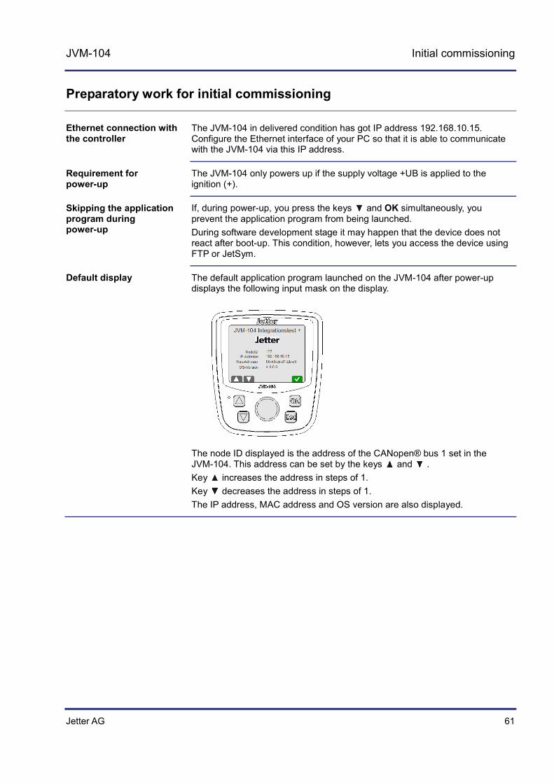
The default application program launched on the JVM-104 after power-up displays the following input mask on the display.
The node ID displayed is the address of the CANopen® bus 1 set in the JVM-104. This address can be set by the keys and . Key increases the address in steps of 1. Key decreases the address in steps of 1. The IP address, MAC address and OS version are also displayed.
Ethernet connection with the controller
Requirement for power-up
Skipping the application program during power-up
Default display
62 Jetter AG
5 Initial commissioning
Programming in the programming language JetSym STX
JetViewSoft lets you create visualization applications for use on the following platforms:
PC systems HMIs for industrial applications HMIs for mobile applications
JetSym STX lets you access visualization objects and control their representation on the HMI. The programming language JetSym STX lets you program the HMI as if it were a controller. The compiled programs can be processed in the HMI without the need for an external controller. This is made possible by the STX interpreter and the graphical runtime environment JVER (JetView Embedded Runtime). Both form an integral part of the HMI's operating system.
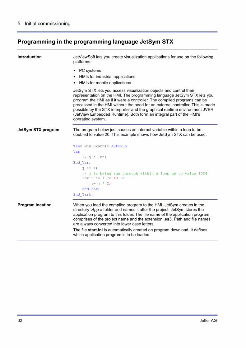
The program below just causes an internal variable within a loop to be doubled to value 20. This example shows how JetSym STX can be used. Task MiniExample AutoRun
Var
i, j : Int;
End_Var;
j := 1;
// j is being run through within a loop up to value 1024 For i := 1 To 10 Do
j := j * 2;
End_For;
End_Task;
When you load the compiled program to the HMI, JetSym creates in the directory \App a folder and names it after the project. JetSym stores the application program to this folder. The file name of the application program comprises of the project name and the extension .es3. Path and file names are always converted into lower case letters. The file start.ini is automatically created on program download. It defines which application program is to be loaded.
Introduction
JetSym STX program
Program location

Jetter AG 63
JVM-104 Initial commissioning
5.2 Configuring a project for the ER-STX-CE platform
This chapter describes how to create and configure in JetViewSoft and JetSym a visualization project for the ER-STX-CE platform.
Topic Page Creating and configuring a visualization project in JetViewSoft ................... 64 Creating and configuring a visualization project in JetSym .......................... 69
Introduction
Contents

64 Jetter AG
5 Initial commissioning
Creating and configuring a visualization project in JetViewSoft
JetViewSoft lets you create visualization files for the JVM-104 and upload them to the HMI. This topic covers the following:
Creating a project in JetViewSoft Defining the project settings. Creating visualization files and uploading them to the HMI.
The following prerequisites must be fulfilled:
JetViewSoft must be installed on the PC. JetViewSoft must be licensed (see Online Help in JetViewSoft). An active Ethernet connection between the PC and the HMI has been set
up.
To create a new project for the HMI in JetViewSoft, proceed as follows:
Step Action
1 Start JetViewSoft
2 Open the File menu. Select menu item New Project. Result: The following dialog box opens:
3 Select in Selected display: the HMI used. To do so, click on the image of the corresponding HMI.
4 In Display name, select a program-internal name for the HMI. You can add one or more HMIs to a project.
5 If the list box Platform isn't grayed out, select JetView-ER-STX(CE).
6 In Project name, enter the name of the project.
7 If necessary, change the project menu path under Location. For the sake of clarity, the end of the path name should be \Visu.
8 Enter the name of the workspace into Workspace.
Introduction
Prerequisites
Creating a project

Jetter AG 65
JVM-104 Initial commissioning
Step Action
The screenshot below shows an example of the completed dialog box:
Important note: The names must not contain blanks. Otherwise, it will be difficult to delete the visualization files at a later date.
9 Confirm your settings by clicking OK. Result: The dialog box closes and the Add New Mask dialog box opens.
10 Enter the name of the first DataMask into the box Name. Leave all other settings unchanged This mask is automatically the active mask when launching the HMI.
11 Confirm the settings by clicking OK.
Result: Creation of the project is completed.
66 Jetter AG
5 Initial commissioning
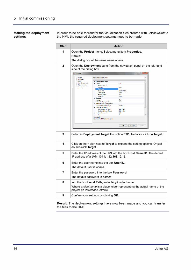
In order to be able to transfer the visualization files created with JetViewSoft to the HMI, the required deployment settings need to be made:
Step Action
1 Open the Project menu. Select menu item Properties. Result: The dialog box of the same name opens.
2 Open the Deployment pane from the navigation panel on the left-hand side of the dialog box.
3 Select in Deployment Target the option FTP. To do so, click on Target.
4 Click on the + sign next to Target to expand the setting options. Or just double-click Target.
5 Enter the IP address of the HMI into the box Host Name/IP. The default IP address of a JVM-104 is 192.168.10.15.
6 Enter the user name into the box User ID. The default user is admin.
7 Enter the password into the box Password. The default password is admin.
8 Into the box Local Path, enter \App\projectname. Where projectname is a placeholder representing the actual name of the project (in lowercase letters).
9 Confirm your settings by clicking OK.
Result: The deployment settings have now been made and you can transfer the files to the HMI.
Making the deployment settings

Jetter AG 67
JVM-104 Initial commissioning
To create a JetViewSoft project and to transfer it to the HMI, proceed as follows:
Step Action
1 Create a screen mask using the available objects (rectangles, ellipses, etc.). Once these objects have been transferred, they can be seen on the HMI.
2 Open the File menu. Select the menu item Save all.
3 Press the [F7] key for a project build. Result: JetViewSoft compiles the project files as long as no error occurs.
4 Open the Build menu. Select menu item Deploy. Another way is to enter the shortcut [CTRL] + [F5]. Result: JetViewSoft transfers the files to the HMI.
5 In order to make the HMI read in the visualization files, restart it.
Result: The files of your JetViewSoft project have been stored to the directory \App\projectname on the HMI. The HMI shows the start screen.
If there is no visualization application on the device, the display shows the following message:
The folder Data is empty. That is, there is no visualization application and no JVER (JetView Embedded Runtime) on the device. If JVER is not running (desktop background is visible), communication with JetSym is not possible. Remedy: Use JetViewSoft to upload a visualization application to the device.
Transferring a project to the HMI
Missing visualization application

68 Jetter AG
5 Initial commissioning
In delivered condition, the HMI may already include a visualization application with an *.iop file stored to the folder Data. This is also the case, if the CAN bus node ID must be set. Result: The HMI will not display your visualization application. Remedy:
Step Action
1 If ... ... then ...
... the file \App\visual.iop or \Data\visual.iop exists,
... delete or rename this file.
2 If ... ... then ...
... the file \App\JetViewERS.cfg exists, ...
... delete or rename this file.
The visualization application developed for the ER-STX-CE platform is displayed.
Initial commissioning in JetSym (see page 69)
IOP file as visualization application on the HMI
Related topics

Jetter AG 69
JVM-104 Initial commissioning
Creating and configuring a visualization project in JetSym
The programming tool JetSym STX lets you create visualization applications for the HMI JVM-104. This topic covers the following:
Creating a project in JetSym STX Configuring the controller hardware Including the visualization library JVER-STX Creating a program that can be compiled and transferred to the HMI
The following requirements must be satisfied:
JetSym has been installed on the PC used. JetSym has been licensed (see online help in JetSym). The controller has been connected to the same network as the PC. An active Ethernet connection between controller, HMI, and PC has been
established. Initial commissioning in JetViewSoft has been completed.
To create a new programming project in JetSym, proceed as follows:
Step Action
1 Launch JetSym.
2 Open the menu File. Select menu item New. Result: The dialog box New opens.
3 Select JetSym STX project as the project type.
4 Enter the project name.
Introduction
Prerequisites
Creating a project

70 Jetter AG
5 Initial commissioning
Step Action
5 Select the path. It is recommended to store project files within a JetViewSoft project to the folder STX. Example: C:\Programs\Jetter\JetViewSoft_Projects\VehicleType_1000\Visu\ VehicleType_1000\VehicleType_1000_Dashboard\STX Advantage: The JetSym project files are located in the same folder as the file VisualInterface.stxp created by JetViewSoft.
6 Confirm your settings by clicking OK.
Result: Creation of the project is completed.
To establish a connection between JetSym and the HMI, you need to configure the hardware.
Step Action
1 Navigate to the tab Hardware and click it.
2 Fully expand the Hardware tree.
3 If you wish to set JVM-C02 as HMI or set interface parameters, double-click CPU. Result: The dialog box Configuration opens.
4 From Controller/Type, select JVM-C02.
Configuring the hardware

Jetter AG 71
JVM-104 Initial commissioning
Step Action
5 From Interface/Type, select Ethernet.
6 Enter the IP address of the HMI into the box Interface/IP address.
7 Test the connection with JVER running by pressing the button Test. If the connection test fails, check the IP address and the Ethernet connection with the JVM-104.
8 Save your settings using the shortcut [Ctrl] + [S].
Result: The hardware settings have been configured in JetSym.
In order for the description of the objects and masks included in the visualization application to be available for programming, the file Visualinterface.stxp must be included as follows:
Step Action
1 Switch to the view Files.
2 Expand the folder Program.
3 Click on the folder Include and open the shortcut menu (by pressing the right mouse button).
4 Select the shortcut menu entry Add Files to Directory. Result: An Explorer window for selecting a file opens.
5 Navigate to the STX folder of the JetViewSoft project. The default location for this is at [Project location]/ Name of the JetViewSoft project/STX.
6 Select here the file VisualInterface.stxp.
VisualInterface.stxp - Include in the project

72 Jetter AG
5 Initial commissioning
Step Action
7 Click the button Open.
Result: The file VisualInterface.stxp is now included into the project.
For the library with its visualization functions to be available in JetSym, you have to include it as follows:
Step Action
1 Open the menu Tools. Select menu item Library Manager.
The dialog box of the same name opens.
2 Click the button Add. Result: An Explorer window opens in the Lib folder of the JetSym installation.
3 Select the file Visualisation_Library_1.0.0.3.libpackage or an up-to-date version of this library.
4 Click the button Open. Result: The library file has now been integrated into the library manager. So, you can now include the library into your JetSym project.
Including a library
Jetter AG 73
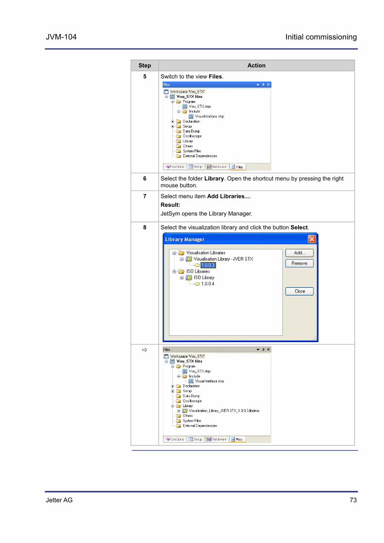
JVM-104 Initial commissioning
Step Action
5 Switch to the view Files.
6 Select the folder Library. Open the shortcut menu by pressing the right mouse button.
7 Select menu item Add Libraries.... Result: JetSym opens the Library Manager.
8 Select the visualization library and click the button Select.

74 Jetter AG
5 Initial commissioning
To create and compile an executable program, proceed as follows:
Step Action
1 Switch to the view Files.
2 Double-click the program file. The program file has the same name as the project, plus the extension stxp. Result: The program file opens in the JetSym editor.
3 Enter the following program code. Mind this when giving the Include instruction. #Include "VisualInterface.stxp"; Function OnKeyDown(KeyCode:long, Flags:long) End_Function; Function OnKeyUp(KeyCode:long, Flags:long) End_Function; Task Main Autorun End_Task;
4 Press the [F7] key to trigger the build process for this project. Result: The visualization functions and the VisualInterface header file are now available for programming.
Result: You can expand the program now. In IntelliSense (Ctrl + Space bar), the visualization functions and the information from the VisualInterface header file are now available. You can transfer the program to the HMI by the shortcut [Strg] + [F5]. However, the program has no function as yet.
Creating a compilable program

Jetter AG 75
JVM-104 Initial commissioning
The functions OnKeyDown and OnKeyUp let you trigger, for example, visualization commands when a key is pressed or released. The operating system returns a specific key code to the function depending on what key you press. The following key codes, for example, are assigned to the keys [UP], [DOWN], [OK] and [ESC]:
Key Key code Constant
0x26 KEY_UP
0x28 KEY_DOWN
OK 0x0D KEY_RETURN
ESC 0x1B KEY_ESCAPE
The file VISU_Defines.stxp holds the key codes assigned to individual keys as constants. This lets you use constants in the application program. A sample STX program is listed below: #include "VisualInterface.stxp"
Function OnKeyDown(KeyCode:LONG, Flags:Long)
Case KeyCode Of
KEY_UP: VisuCmdAttribute(Ellipse_4000, ELLIPSE_ATTR_FILLATTRIBUTE, FillAttribute_26000);
Break;
KEY_DOWN: VisuCmdAttribute(Ellipse_4000, ELLIPSE_ATTR_FILLATTRIBUTE, FillAttribute_26001);
Break;
KEY_RETURN: VisuCmdAttribute(Ellipse_4000, ELLIPSE_ATTR_FILLATTRIBUTE, FillAttribute_26002);
Break;
KEY_ESCAPE: VisuCmdAttribute(Ellipse_4000, ELLIPSE_ATTR_FILLATTRIBUTE, FillAttribute_26003);
Break;
End_Case;
End_Function;
It is advisable to use for Ellipse_4000 and FillAttribute_26000 object names that are more descriptive. This makes it easier to find these objects and to assign them properly. Instead of FillAttribute_26000 you could name it, for example, FillAttribute_White. Blanks or special characters (ä, ö, ü, ß, -, ...) are not allowed for object names. JetViewSoft lets you enter object names in the properties pane of the corresponding object. JetViewSoft incorporates this object name and the object ID into the file VisualInterface.stxp. Then, you can use the object name and ID in the program.
Functions OnKeyDown and OnKeyUp
Recommendations

76 Jetter AG
5 Initial commissioning
Initial commissioning in JetViewSoft (see page 64)
Related topics
Jetter AG 77
JVM-104 Initial commissioning
5.3 ER-STX-CE platform - Programming
This chapter consists of the following two parts:
Entering data via digipot on the HMI Making changes to visualization objects through visualization commands
(VisuCommands) from within the application program.
This description applies to the platform JetView ER-STX-CE/PC.
For more information refer to the JetSym and JetViewSoft online help.
Topic Page Entering data via digipot ............................................................................... 78 Using visualization commands to manipulate visualization objects ............. 82
Introduction
Prerequisites
Additional information
Contents
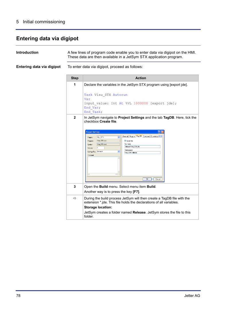
78 Jetter AG
5 Initial commissioning
Entering data via digipot
A few lines of program code enable you to enter data via digipot on the HMI. These data are then available in a JetSym STX application program.
To enter data via digipot, proceed as follows:
Step Action
1 Declare the variables in the JetSym STX program using [export jde]. Task Visu_STX Autorun Var input_value: Int At %VL 1000000 [export jde]; End_Var; End_Task;
2 In JetSym navigate to Project Settings and the tab TagDB. Here, tick the checkbox Create file.
3 Open the Build menu. Select menu item Build.
Another way is to press the key [F7].
During the build process JetSym will then create a TagDB file with the extension *.jde. This file holds the declarations of all variables. Storage location: JetSym creates a folder named Release. JetSym stores the file to this folder.
Introduction
Entering data via digipot
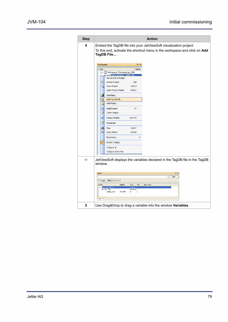
Jetter AG 79
JVM-104 Initial commissioning
Step Action
4 Embed the TagDB file into your JetViewSoft visualization project. To this end, activate the shortcut menu in the workspace and click on Add TagDB File... .
JetViewSoft displays the variables declared in the TagDB file in the TagDB window.
5 Use Drag&Drop to drag a variable into the window Variables.

80 Jetter AG
5 Initial commissioning
Step Action
JetViewSoft creates a variable of the type Number Variable as an object. This is how the window Variables looks like:
This is what the tab ObjectPool looks like:
If the TagDB file contains controller information, JetViewSoft creates a controller and links it with the variables.
6 Use Drag&Drop to drag the variable from the window Variables or ObjectPool to the visualization object Edit Numeric. When the PLUS sign appears, release the mouse button. Result: A link between visualization object and variable has been created.
7 Select the corresponding dynamic feature, such as I/O.
Result: JetViewSoft adds the variable and dynamic feature to the object properties.

Jetter AG 81
JVM-104 Initial commissioning
Step Action
8 In JetSym and JetViewSoft, carry out the commands Build and Deploy. Result: The application is now available on the HMI.
9 Restart the HMI.
Result: The HMI shows the start screen. Now, you can use the digipot to enter a value in the object Edit Numeric. If you enter in the JetSym setup pane register number R 1000000, JetSym displays the set value.

82 Jetter AG
5 Initial commissioning
Using visualization commands to manipulate visualization objects
Visualization commands are functions included in the JetSym visualization library. These function can be invoked in the JetSym STX program. Thus, visualization commands let you manipulate visualization objects directly from within the JetSym STX program. The description below shows how to change, for example, the fill color of an ellipse using the corresponding visualization command.
All available commands have been declared in the file VISU_Functions.stxp. Predefined data types, such as the color as RGB value, attributes and key codes have been declared in the file VISU_Defines.stxp. Both files form an integral part of the visualization library.
For the compiler to compile the following program without errors, add the program code listed below to the sample programs:
#Include "VisualInterface.stxp";
Function OnKeyDown (KeyCode:long, Flags:long)
End_Function;
Function OnKeyUp (KeyCode:long, Flags:long)
End_Function;
The application program is to control the color change of an ellipse through the fill color attribute. After 5 seconds the fill color is to change from red to blue and after another 5 seconds back from blue to red.
The application program invokes the function VisuCmdAttribute() at regular intervals (cycles).
Var
Flag: Bool At %MX 1;
End_Var;
Task Visu_STX Autorun
Flag := FALSE;
Loop
If Flag = FALSE Then
Flag := TRUE;
ELSE
Flag := FALSE;
End_If;
Case Flag Of
TRUE: VisuCmdAttribute (Ellipse_4000, ELLIPSE_ATTR_FILLATTRIBUTE, FillAttribute_Blue);
Break;
FALSE: VisuCmdAttribute (Ellipse_4000, ELLIPSE_ATTR_FILLATTRIBUTE, FillAttribute_Red);
Break;
Introduction
Components of the visualization library
Prerequisites
Task 1
Task 1 - Solution
Task 1 – JetSym STX program
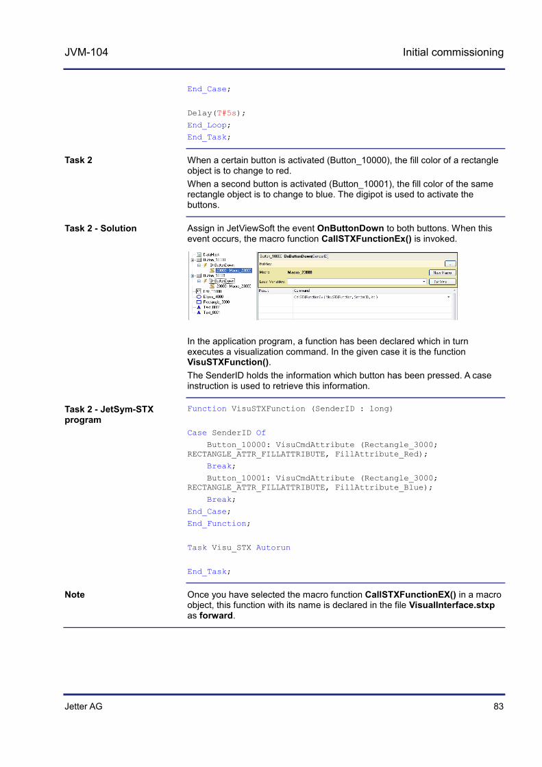
Jetter AG 83
JVM-104 Initial commissioning
End_Case;
Delay(T#5s);
End_Loop;
End_Task;
When a certain button is activated (Button_10000), the fill color of a rectangle object is to change to red. When a second button is activated (Button_10001), the fill color of the same rectangle object is to change to blue. The digipot is used to activate the buttons.
Assign in JetViewSoft the event OnButtonDown to both buttons. When this event occurs, the macro function CallSTXFunctionEx() is invoked.
In the application program, a function has been declared which in turn executes a visualization command. In the given case it is the function VisuSTXFunction(). The SenderID holds the information which button has been pressed. A case instruction is used to retrieve this information.
Function VisuSTXFunction (SenderID : long)
Case SenderID Of
Button_10000: VisuCmdAttribute (Rectangle_3000; RECTANGLE_ATTR_FILLATTRIBUTE, FillAttribute_Red);
Break;
Button_10001: VisuCmdAttribute (Rectangle_3000; RECTANGLE_ATTR_FILLATTRIBUTE, FillAttribute_Blue);
Break;
End_Case;
End_Function;
Task Visu_STX Autorun
End_Task;
Once you have selected the macro function CallSTXFunctionEX() in a macro object, this function with its name is declared in the file VisualInterface.stxp as forward.
Task 2
Task 2 - Solution
Task 2 - JetSym-STX program
Note

Jetter AG 85
JVM-104 CANopen® STX API
6 CANopen® STX API
This chapter describes the STX functions of the CANopen® STX API.
CANopen® is an open standard for networking and communication, for instance, in the automobile sector. The CANopen® protocol has been further developed by the CiA e.V. (CAN in Automation) and works on the physical layer with CAN Highspeed in accordance with ISO 11898.
The CANopen® specifications can be obtained from the CiA e.V. http://www.can-cia.org homepage. The key specification documents are:
CiA DS 301 - This document is also known as the communication profile and describes the fundamental services and protocols used under CANopen®.
CiA DS 302 - Framework for programmable devices (CANopen® Manager, SDO Manager)
CiA DR 303 - Information on cables and connectors CiA DS 4xx - These documents describe the behavior of a number of
device classes in, what are known as, device profiles.
These STX functions are used in communication between the JVM-104 and other CANopen® nodes.
In this chapter we use the point of view from the higher-level controller, whereas in the document CiA DS 301 the point of view from the devices is used. This is why you need, for example, a PDO-RX macro to invoke the function CanOpenAddPDORx().
In this chapter, the following terms and abbreviations are used:
Term Description
Node ID Node identification number of the device: This ID lets you address the device.
NMT Network management - Netzwerkmanagement
ro Read only access
rw Read/write access
Introduction
The CANopen® standard
Documentation
Application
Note: Take into account the point of view!
Terms and abbreviations

86 Jetter AG
6 CANopen® STX API
Topic Page STX function: CanOpenInit() ......................................................................... 87 STX function: CanOpenSetCommand() ....................................................... 89 STX function: CanOpenUploadSDO() .......................................................... 91 STX function: CanOpenDownloadSDO() ...................................................... 96 STX function: CanOpenAddPDORx() ......................................................... 101 STX function: CanOpenAddPDOTx() ......................................................... 108 Heartbeat monitoring .................................................................................. 114 CANopen® object dictionary for JVM-104 .................................................. 118
Table of contents
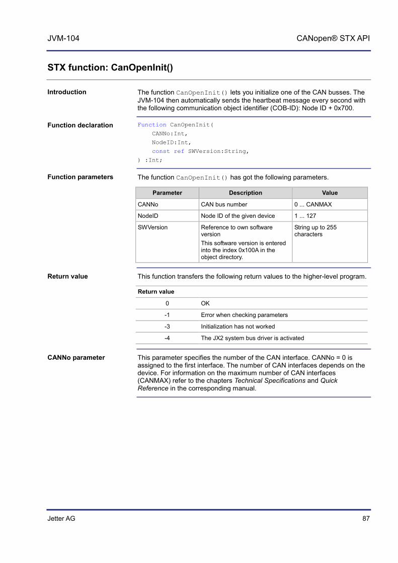
Jetter AG 87
JVM-104 CANopen® STX API
STX function: CanOpenInit()
The function CanOpenInit() lets you initialize one of the CAN busses. The JVM-104 then automatically sends the heartbeat message every second with the following communication object identifier (COB-ID): Node ID + 0x700.
Function CanOpenInit(
CANNo:Int,
NodeID:Int,
const ref SWVersion:String,
) :Int;
The function CanOpenInit() has got the following parameters.
Parameter Description Value
CANNo CAN bus number 0 ... CANMAX
NodeID Node ID of the given device 1 ... 127
SWVersion Reference to own software version This software version is entered into the index 0x100A in the object directory.
String up to 255 characters
This function transfers the following return values to the higher-level program.
Return value
0 OK
-1 Error when checking parameters
-3 Initialization has not worked
-4 The JX2 system bus driver is activated
This parameter specifies the number of the CAN interface. CANNo = 0 is assigned to the first interface. The number of CAN interfaces depends on the device. For information on the maximum number of CAN interfaces (CANMAX) refer to the chapters Technical Specifications and Quick Reference in the corresponding manual.
Introduction
Function declaration
Function parameters
Return value
CANNo parameter
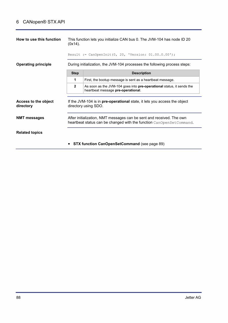
88 Jetter AG
6 CANopen® STX API
This function lets you initialize CAN bus 0. The JVM-104 has node ID 20 (0x14). Result := CanOpenInit(0, 20, 'Version: 01.00.0.00');
During initialization, the JVM-104 processes the following process steps:
Step Description
1 First, the bootup message is sent as a heartbeat message.
2 As soon as the JVM-104 goes into pre-operational status, it sends the heartbeat message pre-operational.
If the JVM-104 is in pre-operational state, it lets you access the object directory using SDO.
After initialization, NMT messages can be sent and received. The own heartbeat status can be changed with the function CanOpenSetCommand.
STX function CanOpenSetCommand (see page 89)
How to use this function
Operating principle
Access to the object directory
NMT messages
Related topics
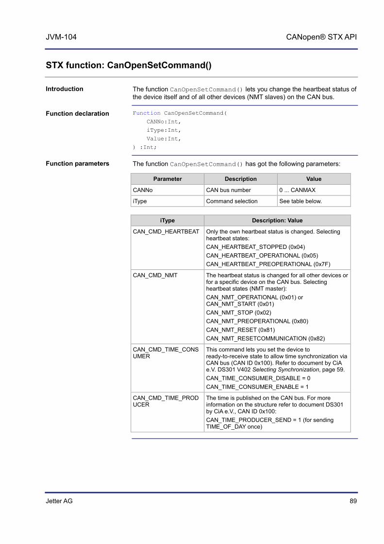
Jetter AG 89
JVM-104 CANopen® STX API
STX function: CanOpenSetCommand()
The function CanOpenSetCommand() lets you change the heartbeat status of the device itself and of all other devices (NMT slaves) on the CAN bus.
Function CanOpenSetCommand(
CANNo:Int,
iType:Int,
Value:Int,
) :Int;
The function CanOpenSetCommand() has got the following parameters:
Parameter Description Value
CANNo CAN bus number 0 ... CANMAX
iType Command selection See table below.
iType Description: Value
CAN_CMD_HEARTBEAT Only the own heartbeat status is changed. Selecting heartbeat states: CAN_HEARTBEAT_STOPPED (0x04) CAN_HEARTBEAT_OPERATIONAL (0x05) CAN_HEARTBEAT_PREOPERATIONAL (0x7F)
CAN_CMD_NMT The heartbeat status is changed for all other devices or for a specific device on the CAN bus. Selecting heartbeat states (NMT master): CAN_NMT_OPERATIONAL (0x01) or CAN_NMT_START (0x01) CAN_NMT_STOP (0x02) CAN_NMT_PREOPERATIONAL (0x80) CAN_NMT_RESET (0x81) CAN_NMT_RESETCOMMUNICATION (0x82)
CAN_CMD_TIME_CONSUMER
This command lets you set the device to ready-to-receive state to allow time synchronization via CAN bus (CAN ID 0x100). Refer to document by CiA e.V. DS301 V402 Selecting Synchronization, page 59. CAN_TIME_CONSUMER_DISABLE = 0 CAN_TIME_CONSUMER_ENABLE = 1
CAN_CMD_TIME_PRODUCER
The time is published on the CAN bus. For more information on the structure refer to document DS301 by CiA e.V., CAN ID 0x100: CAN_TIME_PRODUCER_SEND = 1 (for sending TIME_OF_DAY once)
Introduction
Function declaration
Function parameters

90 Jetter AG
6 CANopen® STX API
The macro function CAN_CMD_NMT_Value(NodeID, CAN_CMD_NMT) is used to select the command CAN_CMD_NMT. Values from 0 to 127 are permitted for the node ID parameter. 1 to 127 is the node ID for a specific device. If the command is to be sent to all devices on the CAN bus, use the parameter CAN_CMD_NMT_ALLNODES(0).
This parameter specifies the number of the CAN interface. CANNo = 0 is assigned to the first interface. The number of CAN interfaces depends on the device. For information on the maximum number of CAN interfaces (CANMAX) refer to the chapters Technical Specifications and Quick Reference in the corresponding manual.
This function sends the following return values to the higher-level program.
Return value
0 OK
-1 Error when checking parameters Command not known
Task: Set the own heartbeat status to operational. Result := CanOpenSetCommand(0, CAN_CMD_HEARTBEAT, CAN_HEARTBEAT_OPERATIONAL);
Task: Set the own heartbeat status and the status of all other devices on the CAN bus to operational. Result := CanOpenSetCommand(0, CAN_CMD_NMT, CAN_CMD_NMT_Value(CAN_CMD_NMT_ALLNODES, CAN_NMT_OPERATIONAL));
Task: Set the heartbeat status of the device with the node ID 60 (0x3C) to operational. Result := CanOpenSetCommand(0, CAN_CMD_NMT, CAN_CMD_NMT_Value(60, CAN_NMT_OPERATIONAL));
Task: Enable time synchronization via CAN bus (CAN ID 0x100). Result := CanOpenSetCommand(0, CAN_CMD_TIME_CONSUMER, CAN_TIME_CONSUMER_ENABLE);
Task: Publish the time on the CAN bus. Result := CanOpenSetCommand(0, CAN_CMD_TIME_PRODUCER, CAN_TIME_PRODUCER_SEND);
Note
CANNo parameter
Return value
How to use this function (example 1)
How to use this function (example 2)
How to use this function (example 3)
How to use this function (example 4)
How to use this function (example 5)

Jetter AG 91
JVM-104 CANopen® STX API
STX function: CanOpenUploadSDO()
The function CanOpenUploadSDO() lets you access a particular object in the object directory of the message recipient and read the value of the object. Data is exchanged in accordance with the SDO upload protocol. Supported transfer types are segmented (more than 4 data bytes) and expedited (up to 4 data bytes).
Function CanOpenUploadSDO(
CANNo:Int, // Number of the bus line
NodeID:Int, // Device ID
wIndex:Word,
SubIndex:Byte,
DataType:Int, // Type of the data to be received
// Data length for the global variable DataAddr DataLength:Int,
// Global variable into which the received value is entered const ref DataAddr,
ref Busy: Int, // Status of the SDO transmission
) :Int;
The CanOpenUploadSDO() function has got the following parameters:
Parameter Description Value
CANNo CAN bus number 0 ... CANMAX
NodeID Node ID of the message recipient
1 ... 127
wIndex Index number of the object 0 ... 0xFFFF
SubIndex Subindex number of the object 0 ... 255
DataType Type of data to be received 2 ... 27
DataLength Data length of the global variable DataAddr
DataAddr Global variable into which the received value is to be entered
Busy Status of the SDO transmission
Introduction
Function declaration
Function parameters
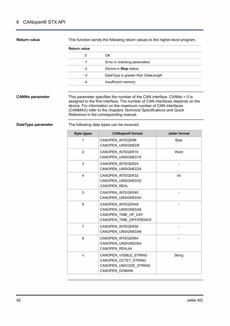
92 Jetter AG
6 CANopen® STX API
This function sends the following return values to the higher-level program.
Return value
0 OK
-1 Error in checking parameters
-2 Device in Stop status
-3 DataType is greater than DataLength
-4 Insufficient memory
This parameter specifies the number of the CAN interface. CANNo = 0 is assigned to the first interface. The number of CAN interfaces depends on the device. For information on the maximum number of CAN interfaces (CANMAX) refer to the chapters Technical Specifications and Quick Reference in the corresponding manual.
The following data types can be received.
Byte types CANopen® format Jetter format
1 CANOPEN_INTEGER8 CANOPEN_UNSIGNED8
Byte
2 CANOPEN_INTEGER16 CANOPEN_UNSIGNED16
Word
3 CANOPEN_INTEGER24 CANOPEN_UNSIGNED24
-
4 CANOPEN_INTEGER32 CANOPEN_UNSIGNED32 CANOPEN_REAL
Int
5 CANOPEN_INTEGER40 CANOPEN_UNSIGNED40
-
6 CANOPEN_INTEGER48 CANOPEN_UNSIGNED48 CANOPEN_TIME_OF_DAY CANOPEN_TIME_DIFFERENCE
-
7 CANOPEN_INTEGER56 CANOPEN_UNSIGNED46
-
8 CANOPEN_INTEGER64 CANOPEN_UNSIGNED64 CANOPEN_REAL64
-
n CANOPEN_VISIBLE_STRING CANOPEN_OCTET_STRING CANOPEN_UNICODE_STRING CANOPEN_DOMAIN
String
Return value
CANNo parameter
DataType parameter

Jetter AG 93
JVM-104 CANopen® STX API
After successfully calling up the function, the Busy parameter is set to SDOACCESS_INUSE. With an error in transmission, Busy is set to SDOACCESS_ERROR. With a successful transmission, the function returns the number of bytes transmitted.
With an error in transmission, Busy returns an error code. The following error codes are available: SDOACCESS_STILLUSED Another task is communicating with the same node ID. SDOACCESS_TIMEOUT The task has been timed out because the device with the specified node ID is not responding. If the specified node ID does not respond within 1 second, the timeout bit is set. SDOACCESS_ILLCMD The response to the request is invalid. SDOACCESS_ABORT Access to the device with the specified node ID was aborted. SDOACCESS_SYSERROR General internal error
The following macros have been defined in connection with this function: SDOACCESS_FINISHED (busy) This macro checks whether communication has finished. SDOACCESS_ERROR (busy) This macro checks whether an error has occurred.
Busy parameter
Busy - Error codes
Macro definitions

94 Jetter AG
6 CANopen® STX API
Result := CanOpenUploadSDO(
0, // CANNo
66, // NodeID
0x100A, // wIndex
0, // SubIndex
CANOPEN_STRING, // DataType
sizeof(var_Versionstring), // DataLength
var_Versionstring, // DataAddr
busy); // Busy
In the following example, the manufacturer's software version is read from the CANopen® Object Directory of the device with the addressed node ID. Const
CANNo = 0; // Number of the bus line
NodeID_Node_0 = 10; // Device ID of node 1
NodeID_Node_0 = 66; // Device ID of node 2
End_Const;
Var
busy: Int;
Versionstring: String;
Objectindex: Word;
Subindex: Byte;
Result: Int;
End_Var;
Task Example_UploadSDO autorun
Var
SW_Version: String;
End_Var;
SW_Version := 'v4.3.0.2004';
// Initializing CAN 0 CanOpenInit(CANNo, // Number of the bus line
NodeID_Node_0, // Node ID
SW_Version); // Manufacturer's software version
// All nodes on the CAN bus are in PREOPERATIONAL state
// Request manufacturer's software version per SDO Objectindex := 0x100A;
Subindex := 0;
How to use this function
JetSym STX program

Jetter AG 95
JVM-104 CANopen® STX API
Result:= CanOpenUploadSDO(CANNo, // Number of the bus line
NodeID_Node_1, // Node ID
Objectindex, // wIndex
Subindex, // SubIndex
CANOPEN_STRING, // DataType
sizeof(Versionstring), // DataLength
Versionstring, // DataAddr
busy); // Busy
// Checking the command for successful execution If (Result == 0) Then
// Waiting until communication is completed When SDOACCESS_FINISHED(busy) Continue;
// Checking for errors If (SDOACCESS_ERROR(busy)) Then
// Troubleshooting End_If;
End_If;
// ... // ... // ...
End_Task;

96 Jetter AG
6 CANopen® STX API
STX function: CanOpenDownloadSDO()
The function CanOpenDownloadSDO() lets you access a particular object in the Object Directory of the message recipient and specify the value of the object. Data is exchanged in accordance with the SDO upload protocol. Supported transfer types are segmented or block (more than 4 data bytes) and expedited (up to 4 data bytes).
Function CanOpenDownloadSDO(
CANNo:Int, // Number of the bus line
NodeID:Int, // Device ID
wIndex:Word,
SubIndex:Byte,
DataType:Int, // Type of the data to be sent
// Data length of the global variable DataAddr DataLength:Int,
// Global variable holding the value to be sent const ref DataAddr,
ref Busy: Int, // Status of the SDO transmission
) :Int;
The CanOpenDownloadSDO() function has got the following parameters:
Parameter Description Value
CANNo CAN bus number 0 ... CANMAX
NodeID Node ID of the message recipient 1 ... 127
wIndex Index number of the object 0 ... 0xFFFF
SubIndex Subindex number of the object 0 ... 255
DataType Type of data to be sent 2 ... 27
DataLength Data length of the global variable DataAddr
DataAddr Global variable into which the value to be sent is to be entered
Busy Status of the SDO transmission
This function sends the following return values to the higher-level program.
Return value
0 OK
-1 Error when checking parameters
-2 Device in Stop status (own heartbeat status)
-3 DataType is greater than DataLength
-4 Insufficient memory
Introduction
Function declaration
Function parameters
Return value
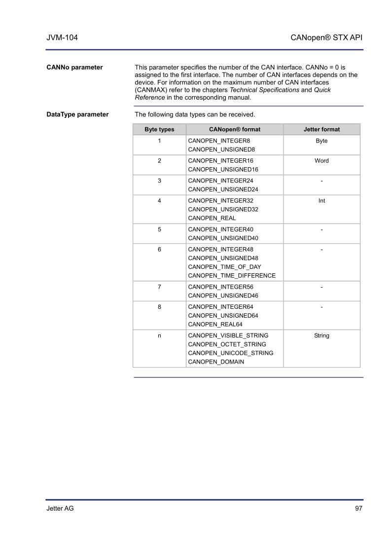
Jetter AG 97
JVM-104 CANopen® STX API
This parameter specifies the number of the CAN interface. CANNo = 0 is assigned to the first interface. The number of CAN interfaces depends on the device. For information on the maximum number of CAN interfaces (CANMAX) refer to the chapters Technical Specifications and Quick Reference in the corresponding manual.
The following data types can be received.
Byte types CANopen® format Jetter format
1 CANOPEN_INTEGER8 CANOPEN_UNSIGNED8
Byte
2 CANOPEN_INTEGER16 CANOPEN_UNSIGNED16
Word
3 CANOPEN_INTEGER24 CANOPEN_UNSIGNED24
-
4 CANOPEN_INTEGER32 CANOPEN_UNSIGNED32 CANOPEN_REAL
Int
5 CANOPEN_INTEGER40 CANOPEN_UNSIGNED40
-
6 CANOPEN_INTEGER48 CANOPEN_UNSIGNED48 CANOPEN_TIME_OF_DAY CANOPEN_TIME_DIFFERENCE
-
7 CANOPEN_INTEGER56 CANOPEN_UNSIGNED46
-
8 CANOPEN_INTEGER64 CANOPEN_UNSIGNED64 CANOPEN_REAL64
-
n CANOPEN_VISIBLE_STRING CANOPEN_OCTET_STRING CANOPEN_UNICODE_STRING CANOPEN_DOMAIN
String
CANNo parameter
DataType parameter

98 Jetter AG
6 CANopen® STX API
After successfully calling up the function, the Busy parameter is set to SDOACCESS_INUSE. With an error in transmission, Busy is set to SDOACCESS_ERROR. With a successful transmission, the function returns the number of bytes transmitted.
With an error in transmission, Busy returns an error code. The following error codes are available: SDOACCESS_STILLUSED Another task is communicating with the same node ID. SDOACCESS_TIMEOUT The task has been timed out because the device with the given node ID is not responding. If the specified node ID does not respond within 1 second, the timeout bit is set. SDOACCESS_ILLCMD The response to the request is invalid. SDOACCESS_ABORT Access to the device with the specified node ID was aborted. SDOACCESS_BLKSIZEINV Communication error with Block Download SDOACCESS_SYSERROR General internal error
The following macros have been defined in connection with this function: SDOACCESS_FINISHED (busy) This macro checks whether communication has finished. SDOACCESS_ERROR (busy) This macro checks whether an error has occurred.
Result := CanOpenDownloadSDO(
0, // CANNo
68, // NodeID
0x1017, // wIndex
0, // SubIndex
CANOPEN_WORD, // DataType
sizeof(var_Heartbeat_time), // DataLength
var_Heartbeat_time, // DataAddr
busy); // Busy
Busy parameter
"Busy" error codes
Macro definitions
How to use this function
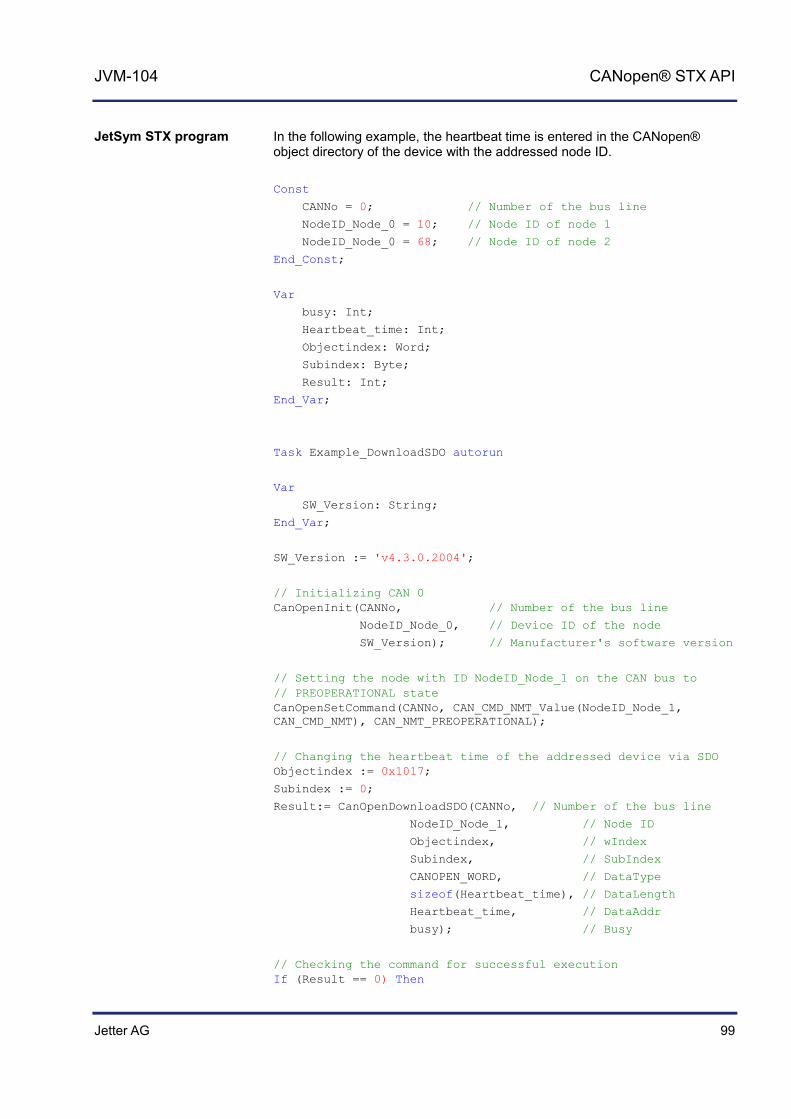
Jetter AG 99
JVM-104 CANopen® STX API
In the following example, the heartbeat time is entered in the CANopen® object directory of the device with the addressed node ID. Const
CANNo = 0; // Number of the bus line
NodeID_Node_0 = 10; // Node ID of node 1
NodeID_Node_0 = 68; // Node ID of node 2
End_Const;
Var
busy: Int;
Heartbeat_time: Int;
Objectindex: Word;
Subindex: Byte;
Result: Int;
End_Var;
Task Example_DownloadSDO autorun
Var
SW_Version: String;
End_Var;
SW_Version := 'v4.3.0.2004';
// Initializing CAN 0 CanOpenInit(CANNo, // Number of the bus line
NodeID_Node_0, // Device ID of the node
SW_Version); // Manufacturer's software version
// Setting the node with ID NodeID_Node_1 on the CAN bus to // PREOPERATIONAL state CanOpenSetCommand(CANNo, CAN_CMD_NMT_Value(NodeID_Node_1, CAN_CMD_NMT), CAN_NMT_PREOPERATIONAL);
// Changing the heartbeat time of the addressed device via SDO Objectindex := 0x1017;
Subindex := 0;
Result:= CanOpenDownloadSDO(CANNo, // Number of the bus line
NodeID_Node_1, // Node ID
Objectindex, // wIndex
Subindex, // SubIndex
CANOPEN_WORD, // DataType
sizeof(Heartbeat_time), // DataLength
Heartbeat_time, // DataAddr
busy); // Busy
// Checking the command for successful execution If (Result == 0) Then
JetSym STX program

100 Jetter AG
6 CANopen® STX API
// Waiting until communication is completed When SDOACCESS_FINISHED(busy) Continue;
// Checking for errors If (SDOACCESS_ERROR(busy)) Then
// Troubleshooting End_If;
End_If;
// Resetting all devices on the CAN bus to OPERATIONAL status CanOpenSetCommand(CANNo, CAN_CMD_NMT_Value(CAN_CMD_NMT_ALLNODES, CAN_CMD_NMT), CAN_NMT_OPERATIONAL);
// ... // ... // ...
End_Task;
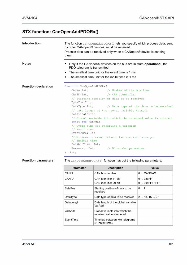
Jetter AG 101
JVM-104 CANopen® STX API
STX function: CanOpenAddPDORx()
The function CanOpenAddPDORx() lets you specify which process data, sent by other CANopen® devices, must be received. Process data can be received only when a CANopen® device is sending them.
Only if the CANopen® devices on the bus are in state operational, the PDO telegram is transmitted.
The smallest time unit for the event time is 1 ms. The smallest time unit for the inhibit time is 1 ms.
Function CanOpenAddPDORx(
CANNo:Int, // Number of the bus line
CANID:Int, // CAN identifier
// Starting position of data to be received BytePos:Int,
DataType:Int, // Data type of the data to be received
// Data length of the global variable VarAddr DataLength:Int,
// Global variable into which the received value is entered const ref VarAddr,
// Cycle time for receiving a telegram // Event time EventTime: Int,
// Minimum interval between two received messages // Inhibit time InhibitTime: Int,
Paramset: Int, // Bit-coded parameter
) :Int;
The CanOpenAddPDORx() function has got the following parameters:
Parameter Description Value
CANNo CAN bus number 0 ... CANMAX
CANID CAN identifier 11-bit CAN identifier 29-bit
0 ... 0x7FF 0 ... 0x1FFFFFFF
BytePos Starting position of data to be received
0 ... 7
DataType Data type of data to be received 2 ... 13, 15 ... 27
DataLength Data length of the global variable VarAddr
VarAddr Global variable into which the received value is entered
EventTime Time lag between two telegrams (> InhibitTime)
Introduction
Notes
Function declaration
Function parameters

102 Jetter AG
6 CANopen® STX API
Parameter Description Value
InhibitTime Minimum time lag between two telegrams received (< EventTime)
Paramset Bit-coded parameter
This function sends the following return values to the higher-level program.
Return value
0 OK
-1 Error when checking parameters
-3 DataType is greater than DataLength
-4 Insufficient memory
This parameter specifies the number of the CAN interface. CANNo = 0 is assigned to the first interface. The number of CAN interfaces depends on the device. For information on the maximum number of CAN interfaces (CANMAX) refer to the chapters Technical Specifications and Quick Reference in the corresponding manual.
In this chapter we use the point of view from the higher-level controller, whereas in the document CiA DS 301 the point of view from the devices is used. This is why you need a PDO-RX macro to invoke the function CanOpenAddPDORx() from the controller.
Return value
CANNo parameter
Note: Take into account the point of view!

Jetter AG 103
JVM-104 CANopen® STX API
The CANID parameter is used to transfer the CAN identifier. The CAN identifier is generated with a macro. The CAN identifier depends on the node ID of the other communicating user and on whether it is a PDO1, PDO2, PDO3 or PDO4 message. Macro definitions: #Define CANOPEN_PDO1_RX (NodeID) ((NodeID) + 0x180) #Define CANOPEN_PDO2_RX (NodeID) ((NodeID) + 0x280) #Define CANOPEN_PDO3_RX (NodeID) ((NodeID) + 0x380) #Define CANOPEN_PDO4_RX (NodeID) ((NodeID) + 0x480) #Define CANOPEN_PDO1_TX (NodeID) ((NodeID) + 0x200) #Define CANOPEN_PDO2_TX (NodeID) ((NodeID) + 0x300) #Define CANOPEN_PDO3_TX (NodeID) ((NodeID) + 0x400) #Define CANOPEN_PDO4_TX (NodeID) ((NodeID) + 0x500) Example for calling up the macro: CANOPEN_PDO2_RX (64) The resulting CAN identifier is: 2C0h = 40h + 280h
For CANopen® the following CAN identifier distribution is predefined. In this case, the node number is embedded in the identifier.
11-bit identifier (binary)
Identifier (decimal)
Identifier (hexadecimal)
Description
000000000000 0 0 Network management
000100000000 128 80h Synchronization
0001xxxxxxxx 129 - 255 81h - FFh Emergency
0011xxxxxxxx 385 - 511 181h - 1FFh PDO1 (tx)
0100xxxxxxxx 513 - 639 201h - 27Fh PDO1 (rx)
0101xxxxxxxx 641 - 767 281h - 2FFh PDO2 (tx)
0110xxxxxxxx 769 - 895 301h - 37Fh PDO2 (rx)
0111xxxxxxxx 897 - 1023 381h - 3FFh PDO3 (tx)
1000xxxxxxxx 1025 - 1151 401h -47Fh PDO3 (rx)
1001xxxxxxxx 1153 - 1279 481h - 4FFh PDO4 (tx)
1010xxxxxxxx 1281 - 1407 501h - 57Fh PDO4 (rx)
1011xxxxxxxx 1409 - 1535 581h - 5FFh Send SDO
1100xxxxxxxx 1537 - 1663 601h - 67Fh Receive SDO
1110xxxxxxxx 1793 - 1919 701h - 77Fh NMT error control
xxxxxxxx = Node number 1 - 127
CANID parameter
Default CAN identifier distribution

104 Jetter AG
6 CANopen® STX API
The following data types can be received.
Byte types CANopen® format Jetter format
1 CANOPEN_INTEGER8 CANOPEN_UNSIGNED8
Byte
2 CANOPEN_INTEGER16 CANOPEN_UNSIGNED16
Word
3 CANOPEN_INTEGER24 CANOPEN_UNSIGNED24
-
4 CANOPEN_INTEGER32 CANOPEN_UNSIGNED32 CANOPEN_REAL
Int
5 CANOPEN_INTEGER40 CANOPEN_UNSIGNED40
-
6 CANOPEN_INTEGER48 CANOPEN_UNSIGNED48 CANOPEN_TIME_OF_DAY CANOPEN_TIME_DIFFERENCE
-
7 CANOPEN_INTEGER56 CANOPEN_UNSIGNED46
-
8 CANOPEN_INTEGER64 CANOPEN_UNSIGNED64 CANOPEN_REAL64
-
n CANOPEN_VISIBLE_STRING CANOPEN_OCTET_STRING CANOPEN_UNICODE_STRING CANOPEN_DOMAIN
String
The following parameters can be transferred to the function. Several parameters can be linked together using the Or function.
CANOPEN_ASYNCPDORTRONLY Receive asynchronous PDOs by sending an RTR frame to the sender (after each expired EventTime). If there is no response to RTR frames, the request time increases to five times the EventTime.
CANOPEN_ASYNCPDO Receive asynchronous PDOs.
CANOPEN_PDOINVALID PDO not received. Disk space is reserved.
CANOPEN_NORTR PDO cannot be requested by RTR (Remote Request). Only if CANOPEN_ASYNCPDORTROnly has been set, an RTR is sent.
CANOPEN_29BIT
DataType parameter
Paramset parameter

Jetter AG 105
JVM-104 CANopen® STX API
Use 29-bit identifier Default: 11-bit identifier
Result := CanOpenAddPDORx(
0, // CANNo
662, // CANID
0, // BytePos
CANOPEN_DWORD, // DataType
sizeof(var_Data_1_of_Node_1), // DataLength
var_Data_1_of_Node_1, // VarAddr
1000, // Event time
10, // Inhibit time
CANOPEN_ASYNCPDO | CANOPEN_NORTR); // Paramset
JVM-104 with node ID 10 wants to receive a PDO from two CANopen® devices with node ID 64 and 102. The function CanOpenAddPDORx() is invoked for this purpose. After running the program, the JVM-104 receives cyclic PDO telegrams.
120 Ohm 120 Ohm
CAN 0
NodeID_Node_0 NodeID_Node_2 NodeID_Node_1
CAN bus
Controller/HMI Device/Module Device/Module
Const
CANNo = 0; // Number of the bus line
NodeID_Node_0 = 10; // Device ID of node 1
NodeID_Node_1 = 64; // Device ID of node 2
NodeID_Node_2 = 102; // Device ID of node 3
Event_Time = 1000; // Event time in ms
Inhibit_Time = 10; // Inhibit time in ms
End_Const;
How to use this function
JetSym STX program
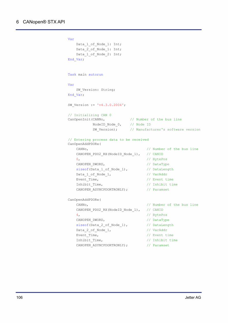
106 Jetter AG
6 CANopen® STX API
Var
Data_1_of_Node_1: Int;
Data_2_of_Node_1: Int;
Data_1_of_Node_2: Int;
End_Var;
Task main autorun
Var
SW_Version: String;
End_Var;
SW_Version := 'v4.3.0.2004';
// Initializing CAN 0 CanOpenInit(CANNo, // Number of the bus line
NodeID_Node_0, // Node ID
SW_Version); // Manufacturer's software version
// Entering process data to be received CanOpenAddPDORx(
CANNo, // Number of the bus line
CANOPEN_PDO2_RX(NodeID_Node_1), // CANID
0, // BytePos
CANOPEN_DWORD, // DataType
sizeof(Data_1_of_Node_1), // DataLength
Data_1_of_Node_1, // VarAddr
Event_Time, // Event time
Inhibit_Time, // Inhibit time
CANOPEN_ASYNCPDORTRONLY); // Paramset
CanOpenAddPDORx(
CANNo, // Number of the bus line
CANOPEN_PDO2_RX(NodeID_Node_1), // CANID
4, // BytePos
CANOPEN_DWORD, // DataType
sizeof(Data_2_of_Node_1), // DataLength
Data_2_of_Node_1, // VarAddr
Event_Time, // Event time
Inhibit_Time, // Inhibit time
CANOPEN_ASYNCPDORTRONLY); // Paramset

Jetter AG 107
JVM-104 CANopen® STX API
CanOpenAddPDORx(
CANNo, // Number of the bus line
CANOPEN_PDO3_RX(NodeID_Node_2), // CANID
0, // BytePos
CANOPEN_BYTE, // DataType
sizeof(Data_1_of_Node_2), // DataLength
Data_1_of_Node_2, // VarAddr
Event_Time, // Event time
Inhibit_Time, // Inhibit time
CANOPEN_ASYNCPDO | CANOPEN_NORTR); // Paramset
// All nodes on the CAN bus are in PREOPERATIONAL state
// Setting all nodes on the CAN bus to OPERATIONAL state CanOpenSetCommand(CANNo, CAN_CMD_NMT_Value(CAN_CMD_NMT_ALLNODES, CAN_CMD_NMT), CAN_NMT_START);
// As of now, PDO telegrams are received/sent // from the higher-level controller // ... // ... // ...
End_Task;

108 Jetter AG
6 CANopen® STX API
STX function: CanOpenAddPDOTx()
By calling up the CanOpenAddPDOTx() function, process data can be deposited on the bus. However, that should not mean that other CANopen® devices on the bus can also read this process data.
Only if the CANopen® devices on the bus are in state operational, the PDO telegram is transmitted.
As soon as there are any changes to the process data, another PDO telegram is transmitted immediately.
The smallest time unit for the event time is 1 ms. The smallest time unit for the inhibit time is 1 ms. Any unused bytes of a telegram are sent as null.
Function CanOpenAddPDOTx(
CANNo:Int, // Number of the bus line
CANID:Int, // CAN identifier
BytePos:Int, // Starting position of the data to be sent
DataType:Int, // Data type of the data to be sent
// Data length of the global variable VarAddr DataLength:Int,
// Global variable holding the value to be sent const ref VarAddr,
// Cycle time for sending a telegram // Event time EventTime: Int,
// Minimum interval between two transmitted messages // Inhibit time InhibitTime: Int,
Paramset: Int, // Bit-coded parameter
) :Int;
The CanOpenAddPDOTx() function has got the following parameters:
Parameter Description Value
CANNo CAN bus number 0 ... CANMAX
CANID CAN identifier 11-bit CAN identifier 29-bit
0 ... 0x7FF 0 ... 0x1FFFFFFF
BytePos Starting position of data to be sent
0 ... 7
DataType Data type of data to be sent 2 ... 13, 15 ... 27
DataLength Data length of the global variable VarAddr
VarAddr Global variable into which the value to be sent is entered
Introduction
Notes
Function declaration
Function parameters
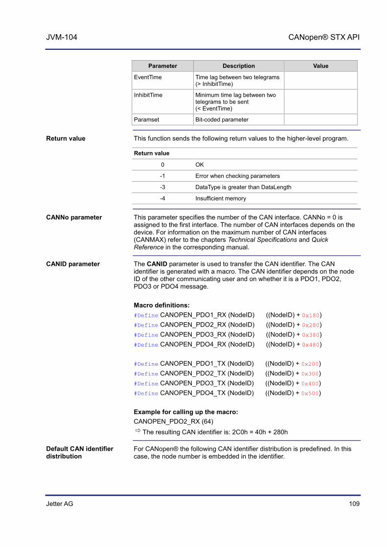
Jetter AG 109
JVM-104 CANopen® STX API
Parameter Description Value
EventTime Time lag between two telegrams (> InhibitTime)
InhibitTime Minimum time lag between two telegrams to be sent (< EventTime)
Paramset Bit-coded parameter
This function sends the following return values to the higher-level program.
Return value
0 OK
-1 Error when checking parameters
-3 DataType is greater than DataLength
-4 Insufficient memory
This parameter specifies the number of the CAN interface. CANNo = 0 is assigned to the first interface. The number of CAN interfaces depends on the device. For information on the maximum number of CAN interfaces (CANMAX) refer to the chapters Technical Specifications and Quick Reference in the corresponding manual.
The CANID parameter is used to transfer the CAN identifier. The CAN identifier is generated with a macro. The CAN identifier depends on the node ID of the other communicating user and on whether it is a PDO1, PDO2, PDO3 or PDO4 message. Macro definitions: #Define CANOPEN_PDO1_RX (NodeID) ((NodeID) + 0x180) #Define CANOPEN_PDO2_RX (NodeID) ((NodeID) + 0x280) #Define CANOPEN_PDO3_RX (NodeID) ((NodeID) + 0x380) #Define CANOPEN_PDO4_RX (NodeID) ((NodeID) + 0x480) #Define CANOPEN_PDO1_TX (NodeID) ((NodeID) + 0x200) #Define CANOPEN_PDO2_TX (NodeID) ((NodeID) + 0x300) #Define CANOPEN_PDO3_TX (NodeID) ((NodeID) + 0x400) #Define CANOPEN_PDO4_TX (NodeID) ((NodeID) + 0x500) Example for calling up the macro: CANOPEN_PDO2_RX (64) The resulting CAN identifier is: 2C0h = 40h + 280h
For CANopen® the following CAN identifier distribution is predefined. In this case, the node number is embedded in the identifier.
Return value
CANNo parameter
CANID parameter
Default CAN identifier distribution

110 Jetter AG
6 CANopen® STX API
11-bit identifier (binary)
Identifier (decimal)
Identifier (hexadecimal)
Description
000000000000 0 0 Network management
000100000000 128 80h Synchronization
0001xxxxxxxx 129 - 255 81h - FFh Emergency
0011xxxxxxxx 385 - 511 181h - 1FFh PDO1 (tx)
0100xxxxxxxx 513 - 639 201h - 27Fh PDO1 (rx)
0101xxxxxxxx 641 - 767 281h - 2FFh PDO2 (tx)
0110xxxxxxxx 769 - 895 301h - 37Fh PDO2 (rx)
0111xxxxxxxx 897 - 1023 381h - 3FFh PDO3 (tx)
1000xxxxxxxx 1025 - 1151 401h -47Fh PDO3 (rx)
1001xxxxxxxx 1153 - 1279 481h - 4FFh PDO4 (tx)
1010xxxxxxxx 1281 - 1407 501h - 57Fh PDO4 (rx)
1011xxxxxxxx 1409 - 1535 581h - 5FFh Send SDO
1100xxxxxxxx 1537 - 1663 601h - 67Fh Receive SDO
1110xxxxxxxx 1793 - 1919 701h - 77Fh NMT error control
xxxxxxxx = Node number 1 - 127
The following data types can be received.
Byte types CANopen® format Jetter format
1 CANOPEN_INTEGER8 CANOPEN_UNSIGNED8
Byte
2 CANOPEN_INTEGER16 CANOPEN_UNSIGNED16
Word
3 CANOPEN_INTEGER24 CANOPEN_UNSIGNED24
-
4 CANOPEN_INTEGER32 CANOPEN_UNSIGNED32 CANOPEN_REAL
Int
5 CANOPEN_INTEGER40 CANOPEN_UNSIGNED40
-
6 CANOPEN_INTEGER48 CANOPEN_UNSIGNED48 CANOPEN_TIME_OF_DAY CANOPEN_TIME_DIFFERENCE
-
7 CANOPEN_INTEGER56 CANOPEN_UNSIGNED46
-
8 CANOPEN_INTEGER64 CANOPEN_UNSIGNED64 CANOPEN_REAL64
-
DataType parameter
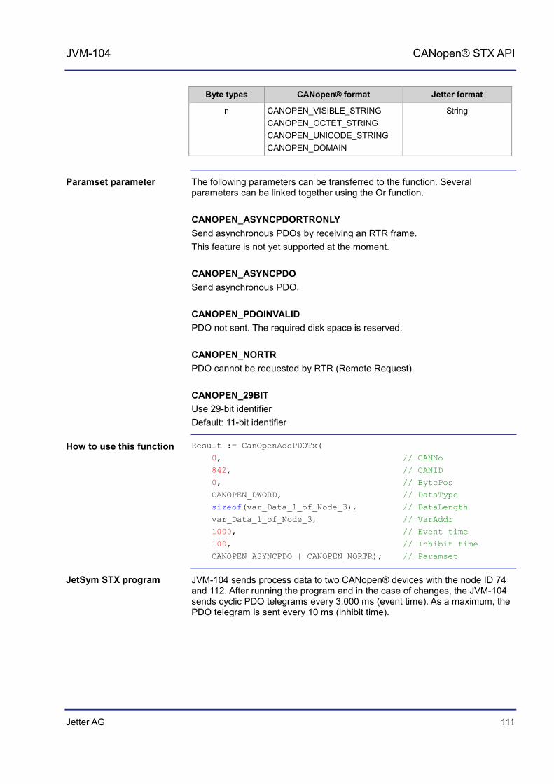
Jetter AG 111
JVM-104 CANopen® STX API
Byte types CANopen® format Jetter format
n CANOPEN_VISIBLE_STRING CANOPEN_OCTET_STRING CANOPEN_UNICODE_STRING CANOPEN_DOMAIN
String
The following parameters can be transferred to the function. Several parameters can be linked together using the Or function. CANOPEN_ASYNCPDORTRONLY Send asynchronous PDOs by receiving an RTR frame. This feature is not yet supported at the moment. CANOPEN_ASYNCPDO Send asynchronous PDO. CANOPEN_PDOINVALID PDO not sent. The required disk space is reserved. CANOPEN_NORTR PDO cannot be requested by RTR (Remote Request). CANOPEN_29BIT Use 29-bit identifier Default: 11-bit identifier
Result := CanOpenAddPDOTx(
0, // CANNo
842, // CANID
0, // BytePos
CANOPEN_DWORD, // DataType
sizeof(var_Data_1_of_Node_3), // DataLength
var_Data_1_of_Node_3, // VarAddr
1000, // Event time
100, // Inhibit time
CANOPEN_ASYNCPDO | CANOPEN_NORTR); // Paramset
JVM-104 sends process data to two CANopen® devices with the node ID 74 and 112. After running the program and in the case of changes, the JVM-104 sends cyclic PDO telegrams every 3,000 ms (event time). As a maximum, the PDO telegram is sent every 10 ms (inhibit time).
Paramset parameter
How to use this function
JetSym STX program
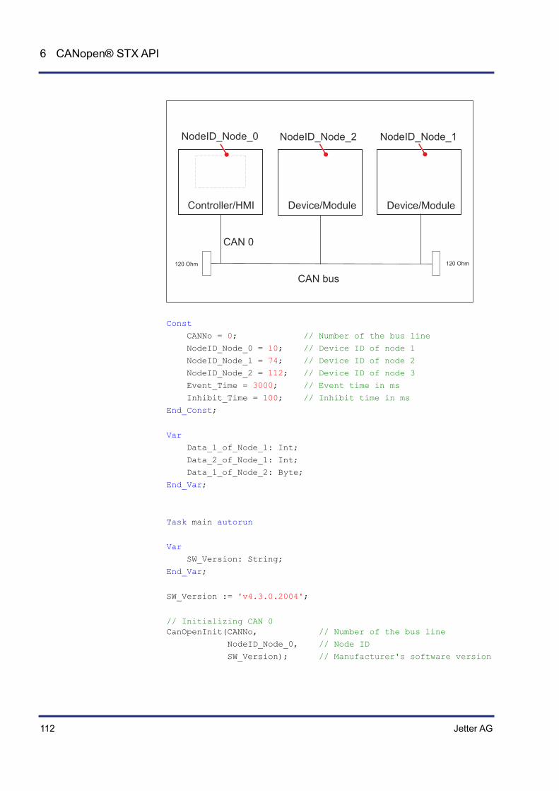
112 Jetter AG
6 CANopen® STX API
120 Ohm 120 Ohm
CAN 0
NodeID_Node_0 NodeID_Node_2 NodeID_Node_1
CAN bus
Controller/HMI Device/Module Device/Module
Const
CANNo = 0; // Number of the bus line
NodeID_Node_0 = 10; // Device ID of node 1
NodeID_Node_1 = 74; // Device ID of node 2
NodeID_Node_2 = 112; // Device ID of node 3
Event_Time = 3000; // Event time in ms
Inhibit_Time = 100; // Inhibit time in ms
End_Const;
Var
Data_1_of_Node_1: Int;
Data_2_of_Node_1: Int;
Data_1_of_Node_2: Byte;
End_Var;
Task main autorun
Var
SW_Version: String;
End_Var;
SW_Version := 'v4.3.0.2004';
// Initializing CAN 0 CanOpenInit(CANNo, // Number of the bus line
NodeID_Node_0, // Node ID
SW_Version); // Manufacturer's software version

Jetter AG 113
JVM-104 CANopen® STX API
// Send data per PDO CanOpenAddPDOTx(
CANNo, // Number of the bus line
CANOPEN_PDO2_TX(NodeID_Node_1), // CANID
0, // BytePos
CANOPEN_DWORD, // DataType
sizeof(Data_1_of_Node_1), // DataLength
Data_1_of_Node_1, // VarAddr
Event_Time, // Event time
Inhibit_Time, // Inhibit time
CANOPEN_ASYNCPDORTRONLY); // Paramset
CanOpenAddPDOTx(
CANNo, // Number of the bus line
CANOPEN_PDO2_TX(NodeID_Node_1), // CANID
4, // BytePos
CANOPEN_DWORD, // DataType
sizeof(Data_2_of_Node_1), // DataLength
Data_2_of_Node_1, // VarAddr
Event_Time, // Event time
Inhibit_Time, // Inhibit time
CANOPEN_ASYNCPDORTRONLY); // Paramset
CanOpenAddPDOTx(
CANNo, // Number of the bus line
CANOPEN_PDO3_TX(NodeID_Node_2), // CANID
0, // BytePos
CANOPEN_BYTE, // DataType
sizeof(Data_1_of_Node_2), // DataLength
Data_1_of_Node_2, // VarAddr
Event_Time, // Event time
Inhibit_Time, // Inhibit time
CANOPEN_ASYNCPDO | CANOPEN_NORTR); // Paramset
// All nodes on the CAN bus are in PREOPERATIONAL state
// Setting all nodes on the CAN bus to OPERATIONAL state CanOpenSetCommand(CANNo, CAN_CMD_NMT_Value(CAN_CMD_NMT_ALLNODES, CAN_CMD_NMT), CAN_NMT_START);
// As of now, PDO telegrams will be transmitted from the devices with node ID 74 // and 112. // ...
End_Task;

114 Jetter AG
6 CANopen® STX API
Heartbeat monitoring
The heartbeat protocol is for monitoring the activity of communication partners. If the inactivity exceeds the set interval (Heartbeat consumer time), the status is set to offline. The application program lets you define heartbeat functions, such as
Displaying information to the user Rebooting the device Ignoring process data
Heartbeat monitoring is available only for specific devices and its availability depends on the OS version.
Device OS version
FMC-01 1.18.1.00 or higher
JVM-C02 4.00.0.00 or higher
JCM-350 1.09.0.215 or higher
JCM-620 JVER bersion 3.2.2.645 and JetVM version 3.04.0.00 or higher
Heartbeat monitoring uses the following registers:
Register Description Data type Attributes
40x001 Own heartbeat status of the device; Value range: 0 = Bootup 4 = Stopped 5 = Operational 127 = Preoperational 255 = Offline (default value)
Int ro (read only)
40x100 The heartbeat status of all monitored node IDs has changed. Value range: 0 = False 1 = True
Bool rw (read and write)
40x101 ... 40x227
Heartbeat status of nodes with ID 1 ... 127; value range: 0 = Bootup 4 = Stopped 5 = Operational 127 = Preoperational 255 = Offline (default value)
Byte ro
40x229 ... 40x355
Heartbeat timeout of nodes with ID 1 ... 127; value range: 0 ... 65535 [ms]
Word rw
Introduction
Prerequisites
Registers for heartbeat monitoring

Jetter AG 115
JVM-104 CANopen® STX API
In the register number, the letter x represents the number of the CAN bus line used: x = 0 ... CANMAX.
To launch heartbeat monitoring, proceed as follows:
Step Action
1 Enable heartbeat monitoring: Enter the timeout value into the corresponding register. This value must range between 1 and 65535 [ms]. Example: For CAN 0 and node ID 1: Enter a timeout value of 3000 [ms] into register 400229.
2 Define in your application program how the device is to respond to individual values in the heartbeat status register. When the state in register 40x101 ... 40x227 changes, the value in register 40x100 changes to 1 (true).
3 Reset the value in register 40x100 to zero (false). This step ensures that subsequent changes in register 40x101 ... 40x227 can be displayed.
Heartbeat monitoring starts on receipt of the first heartbeat (including bootup message). The DLC (Data Length Code) of the heartbeat message must be 1.
To terminate heartbeat monitoring, proceed as follows:
Step Action
1 Disable heartbeat monitoring: Enter a timeout value of 0 [ms] into the timeout register.
When a heartbeat timeout is detected, an emergency message is sent automatically. On receipt of the next heartbeat message, the emergency message is reset.
Example: The following emergency message is tripped:
Reference Value
Error code 0x8130
Error Register 0x81
Manufacturer error 0x00,NodeID,0x00,0x00,0x00
The message on the CAN bus looks as shown below:
Own NodeID 5 Monitored NodeID 1 ID: 0x85 DLC = 8 Data: 0x30 0x81 0x81 0x00 0x01 0x00 0x00 0x00
Launching heartbeat monitoring
Terminating heartbeat monitoring
Emergency message

116 Jetter AG
6 CANopen® STX API
The declaration of the emergency message Rx consists of the following elements:
CanOpenAddEmergencyRx(
CANNo:Int, // Number of the bus line
NodeID:Int, // Node ID
// Status, number of valid messages ref stCanOpenEmergencyStat:CanOpenEmergencyStat,
// Array holding the emergency messages ref CanOpenEmergencyMSG:CanOpenEmergencyArray,
):int
Example: The above program lines must be included into the corresponding tasks of your application program. The example below shows an emergency message from a device with node ID 21.
...
// Initializing the CAN bus once. ...
// Defining global variables Var
stCanOpenEmergencyMsg : ARRAY[5] of CanOpenEmergencyMsg;
stCanOpenEmergencyStat : CanOpenEmergencyStat;
End_Var;
stCanOpenEmergencyStat.lBuffer := sizeof(stCanOpenEmergencyMsg);
iRet:= CanOpenAddEmergencyRx(0, // CANNo.
21, // NodeID
stCanOpenEmergencyStat, // Status
stCanOpenEmergencyMsg); // Array
...
The above program lines produce the following result: When the device with node ID 21 receives an emergency message, the value in register 400100 switches from 0 to 1 (true). Reset this value always to 0 (false). In doing so, you make sure that new emergency messages are displayed.
Emergency message Rx
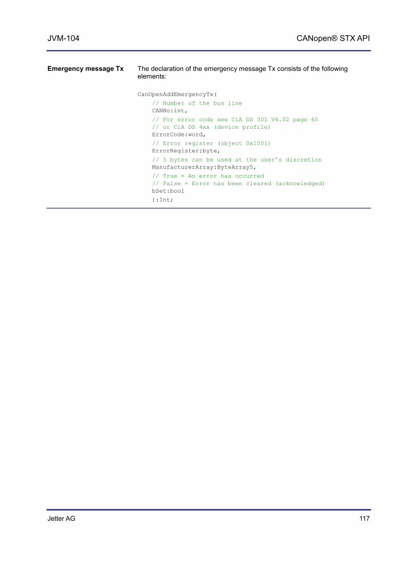
Jetter AG 117
JVM-104 CANopen® STX API
The declaration of the emergency message Tx consists of the following elements:
CanOpenAddEmergencyTx(
// Number of the bus line CANNo:int,
// For error code see CiA DS 301 V4.02 page 60 // or CiA DS 4xx (device profile) ErrorCode:word,
// Error register (object 0x1001) ErrorRegister:byte,
// 5 bytes can be used at the user's discretion ManufacturerArray:ByteArray5,
// True = An error has occurred // False = Error has been cleared (acknowledged) bSet:bool
):Int;
Emergency message Tx
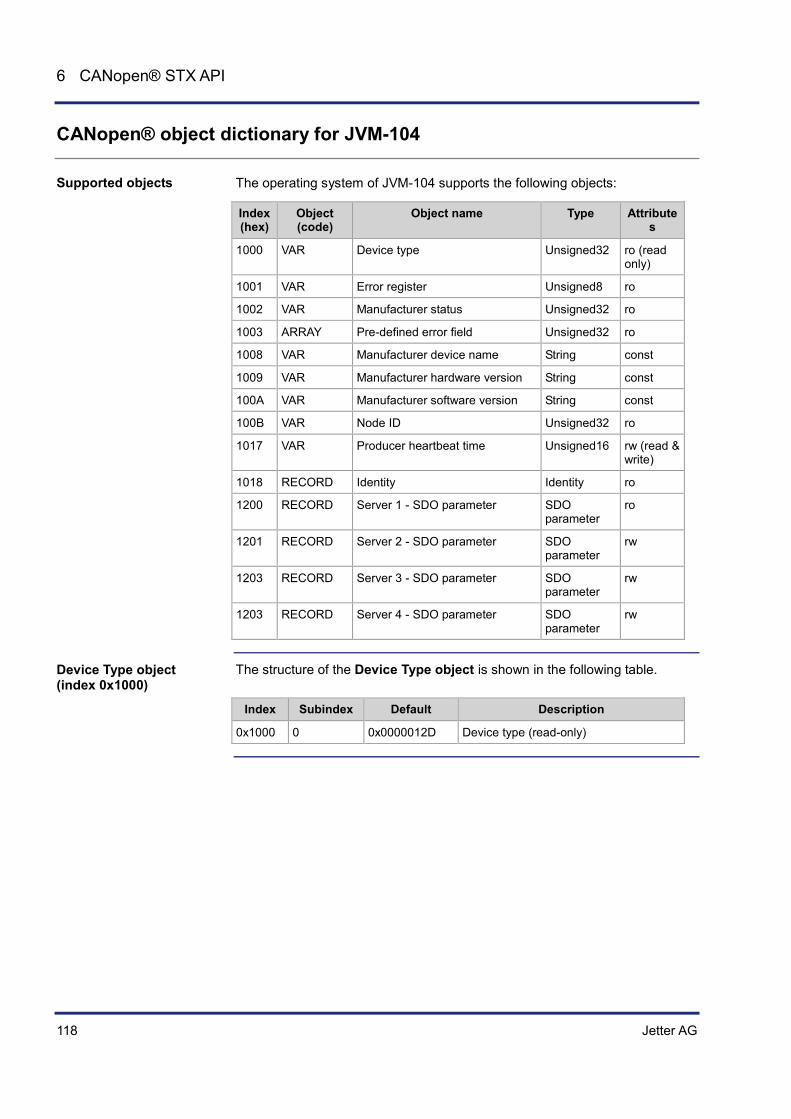
118 Jetter AG
6 CANopen® STX API
CANopen® object dictionary for JVM-104
The operating system of JVM-104 supports the following objects:
Index (hex)
Object (code)
Object name Type Attributes
1000 VAR Device type Unsigned32 ro (read only)
1001 VAR Error register Unsigned8 ro
1002 VAR Manufacturer status Unsigned32 ro
1003 ARRAY Pre-defined error field Unsigned32 ro
1008 VAR Manufacturer device name String const
1009 VAR Manufacturer hardware version String const
100A VAR Manufacturer software version String const
100B VAR Node ID Unsigned32 ro
1017 VAR Producer heartbeat time Unsigned16 rw (read & write)
1018 RECORD Identity Identity ro
1200 RECORD Server 1 - SDO parameter SDO parameter
ro
1201 RECORD Server 2 - SDO parameter SDO parameter
rw
1203 RECORD Server 3 - SDO parameter SDO parameter
rw
1203 RECORD Server 4 - SDO parameter SDO parameter
rw
The structure of the Device Type object is shown in the following table.
Index Subindex Default Description
0x1000 0 0x0000012D Device type (read-only)
Supported objects
Device Type object (index 0x1000)
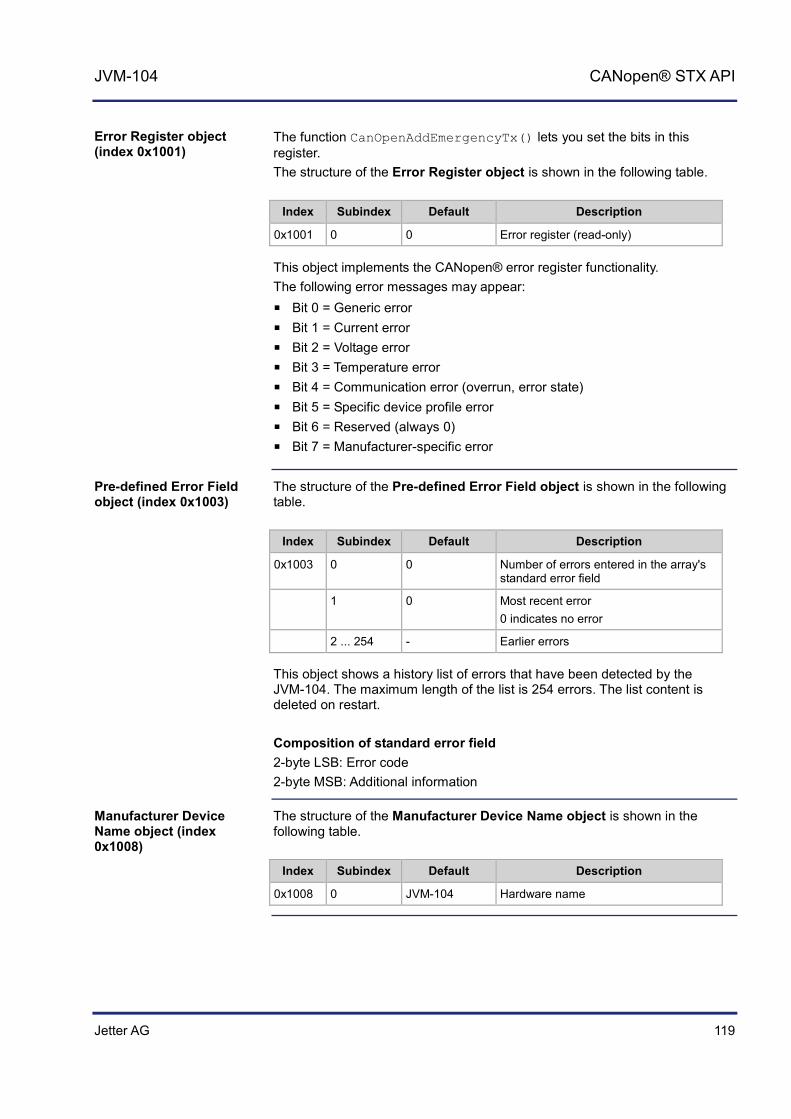
Jetter AG 119
JVM-104 CANopen® STX API
The function CanOpenAddEmergencyTx() lets you set the bits in this register. The structure of the Error Register object is shown in the following table.
Index Subindex Default Description
0x1001 0 0 Error register (read-only)
This object implements the CANopen® error register functionality. The following error messages may appear:
Bit 0 = Generic error Bit 1 = Current error Bit 2 = Voltage error Bit 3 = Temperature error Bit 4 = Communication error (overrun, error state) Bit 5 = Specific device profile error Bit 6 = Reserved (always 0) Bit 7 = Manufacturer-specific error
The structure of the Pre-defined Error Field object is shown in the following table.
Index Subindex Default Description
0x1003 0 0 Number of errors entered in the array's standard error field
1 0 Most recent error 0 indicates no error
2 ... 254 - Earlier errors
This object shows a history list of errors that have been detected by the JVM-104. The maximum length of the list is 254 errors. The list content is deleted on restart. Composition of standard error field 2-byte LSB: Error code 2-byte MSB: Additional information
The structure of the Manufacturer Device Name object is shown in the following table.
Index Subindex Default Description
0x1008 0 JVM-104 Hardware name
Error Register object (index 0x1001)
Pre-defined Error Field object (index 0x1003)
Manufacturer Device Name object (index 0x1008)

120 Jetter AG
6 CANopen® STX API
The structure of the Manufacturer Hardware Version object is shown in the following table.
Index Subindex Default Description
0x1009 0 OS version of the device
The structure of the Manufacturer Software Version object is shown in the following table.
Index Subindex Default Description
0x100A 0 Software version of the application program that runs on the JVM-104
The entry in this index is made via the parameter SWVersion of the STX function CanOpenInit().
The structure of the Node ID object is shown in the following table.
Index Subindex Default Description
0x100B 0 Node ID of the given device
The structure of the Producer Heartbeat Time object is shown in the following table.
Index Subindex Default Description
0x1017 0 1,000 [ms] Heartbeat time
The table below lists the JVM-104 registers associated with the CANopen® Object Dictionary. The letter x in the register number represents the CAN bus number ranging from 0 ... CANMAX.
Register number
Description Value range Attributes Data type
40x000 Own node ID 1 ... 127 rw (read & write)
Int
40x001 Own heartbeat status
0 = Bootup 4 = Stopped 5 = Operational 127 = Preoperational 255 = Offline
ro (read only)
Int
40x002 Refer to object 0x1001
ro Int
40x019 ro Int (IP format)
Manufacturer Hardware Version object (index 0x1009)
Manufacturer Software Version object (index 0x100A)
Node ID object (index 0x100B)
Producer Heartbeat Time object (index 0x1017)
CANopen® registers - JVM-104

Jetter AG 121
JVM-104 CANopen® STX API
Register number
Description Value range Attributes Data type
40x020 rw Int
40x021 rw Int
40x022 rw Int
40x023 rw Int
40x030 rw Int
40x100 rw bool
40x400 rw bool
40x101 ... 40x227
Node ID 1 ... 127 Status
0 = Bootup 4 = Stopped 5 = Operational 127 = Preoperational 255 = Offline (default)
ro byte
40x229 ... 40x355
Node ID 1 ... 127 timeout
0 ... 65535 ms rw word


Jetter AG 123
JVM-104 SAE J1939 STX API
7 SAE J1939 STX API
This chapter describes the STX functions of the SAE J1939 STX API.
SAE J1939 is an open standard for networking and communication in the commercial vehicle sector. The focal point of the application is the networking of the power train and chassis. The J1939 protocol originates from the international Society of Automotive Engineers (SAE) and works on the physical layer with CAN high-speed according to ISO 11898.
These STX functions are used in communication between the controller JVM-104 and other ECUs in the vehicle. As a rule, engine data, such as RPM, speed or coolant temperature are read and displayed.
The key SAE J1939 specifications are:
J1939-11 - Information on the physical layer J1939-21 - Information on the data link layer J1939-71 - Information on the application layer vehicles J1939-73 - Information on the application layer range analysis J1939-81 - Network management
Topic Page Content of a J1939 message ...................................................................... 124 STX Function SAEJ1939Init() ..................................................................... 126 STX function SAEJ1939SetSA() ................................................................ 127 STX function SAEJ1939GetSA() ................................................................ 128 STX function SAEJ1939AddRx() ................................................................ 129 STX function SAEJ1939AddTx() ................................................................ 132 STX function SAEJ1939RequestPGN() ..................................................... 135 STX function SAEJ1939GetDM1() ............................................................. 138 STX function SAEJ1939GetDM2() ............................................................. 141 STX function SAEJ1939SetSPNConversion() ........................................... 144 STX Function SAEJ1939GetSPNConversion() .......................................... 145
Introduction
The SAE J1939 Standard
Application
Documentation
Contents
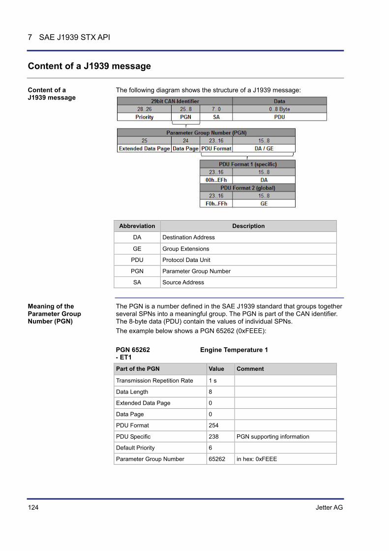
124 Jetter AG
7 SAE J1939 STX API
Content of a J1939 message
The following diagram shows the structure of a J1939 message:
Abbreviation Description
DA Destination Address
GE Group Extensions
PDU Protocol Data Unit
PGN Parameter Group Number
SA Source Address
The PGN is a number defined in the SAE J1939 standard that groups together several SPNs into a meaningful group. The PGN is part of the CAN identifier. The 8-byte data (PDU) contain the values of individual SPNs. The example below shows a PGN 65262 (0xFEEE): PGN 65262 Engine Temperature 1 - ET1
Part of the PGN Value Comment
Transmission Repetition Rate 1 s
Data Length 8
Extended Data Page 0
Data Page 0
PDU Format 254
PDU Specific 238 PGN supporting information
Default Priority 6
Parameter Group Number 65262 in hex: 0xFEEE
Content of a J1939 message
Meaning of the Parameter Group Number (PGN)

Jetter AG 125
JVM-104 SAE J1939 STX API
Start position Length Parameter name SPN
1 1 byte Engine Coolant Temperature 110
2 1 byte Engine Fuel Temperature 1 174
3 - 4 2 bytes Engine Oil Temperature 1 175
5 - 6 2 bytes Engine Turbocharger Oil Temperature 176
7 1 byte Engine Intercooler Temperature 52
8 1 byte Engine Intercooler Thermostat Opening 1134

126 Jetter AG
7 SAE J1939 STX API
STX Function SAEJ1939Init()
Calling up the SAEJ1939Init() function initializes one of the CAN busses (not CAN 0 as this is reserved for CANopen®) for use with the J1939 protocol. From then on, the JVM-104 has got the SA (Source Address) assigned by the function parameter mySA. Thus, it has got its own device address on the bus.
Function SAEJ1939Init(
CANNo:Int,
mySA:Byte,
) :Int;
The SAEJ1939Init() function comprises the following parameters:
Parameter Description Value
CANNo CAN channel number 1 ... CANMAX
mySA Own source address 0 ... 253
This function transfers the following return values to the higher-level program.
Return value
0 OK
-1 Error when checking parameters
-3 Insufficient memory for SAE J1939
This parameter specifies the number of the SAEJ1939 interface. CANNo = 1 is assigned to the first interface. The number of SAEJ1939 interfaces depends on the device. For information on the maximum number of SAEJ1939 interfaces (CANMAX) refer to the chapters Technical Specifications and Quick Reference in the corresponding manual.
Initializing CAN bus 1. The JVM-104 has got Node SA 20 (0x14). The JVM-104 can now send messages with the set SA (and only these messages).
Result := SAEJ1939Init(1, 20);
Address Claiming has not been implemented.
Introduction
Function declaration
Function parameters
Return value
CANNo parameter
How to use this function
Address Claiming
Jetter AG 127
JVM-104 SAE J1939 STX API
STX function SAEJ1939SetSA()
The function SAEJ1939SetSA() lets you change the own SA (Source Address) during runtime.
Function SAEJ1939SetSA(
CANNo:Int,
mySA:Byte,
) :Int;
The function SAEJ1939SetSA() comprises the following parameters:
Parameter Description Value
CANNo CAN channel number 1 ... CANMAX
mySA New SA 0 ... 253
This function transfers the following return values to the higher-level program.
Return value
0 OK
-1 Error when checking parameters
This parameter specifies the number of the SAEJ1939 interface. CANNo = 1 is assigned to the first interface. The number of SAEJ1939 interfaces depends on the device. For information on the maximum number of SAEJ1939 interfaces (CANMAX) refer to the chapters Technical Specifications and Quick Reference in the corresponding manual.
Changing the SA during runtime. Result := SAEJ1939SetSA(1, 20);
Messages are immediately sent/received using the new SA.
Introduction
Function declaration
Function parameters
Return value
CANNo parameter
How to use this function
Important note!

128 Jetter AG
7 SAE J1939 STX API
STX function SAEJ1939GetSA()
The function SAEJ1939GetSA() lets you determine your own SA (Source Address).
Function SAEJ1939GetSA(
CANNo:Int,
ref mySA:Byte,
) :Int;
The function SAEJ1939GetSA() comprises the following parameters:
Parameter Description Value
CANNo CAN channel number 1 ... CANMAX
mySA SA currently set 0 ... 253
This function transfers the following return values to the higher-level program.
Return value
0 OK
-1 Error when checking parameters
This parameter specifies the number of the SAEJ1939 interface. CANNo = 1 is assigned to the first interface. The number of SAEJ1939 interfaces depends on the device. For information on the maximum number of SAEJ1939 interfaces (CANMAX) refer to the chapters Technical Specifications and Quick Reference in the corresponding manual.
This function returns the currently set SA. Result := SAEJ1939SetSA(1, actual_SA);
Introduction
Function declaration
Function parameters
Return value
CANNo parameter
How to use this function

Jetter AG 129
JVM-104 SAE J1939 STX API
STX function SAEJ1939AddRx()
Calling up the function SAEJ1939AddRx() prompts the JVM-104 to receive a specific message. This message is sent from another bus node. The address of this bus node is transferred to this function as a bySA parameter. If the message is not sent, the value received last remains valid. Cyclical reading continues until the function SAEJ1939Init() is called up again.
Function SAEJ1939AddRx(
CANNo:Int,
IPGN:Long,
bySA:Byte,
BytePos:Int,
BitPos:Int,
DataType:Int,
DataLength:Int,
const ref VarAddr,
ref stJ1939:TJ1939Rx
EventTime: Int,
InhibitTime: Int,
) :Int;
The function SAEJ1939AddRx() comprises the following parameters:
Parameter Description Value
CANNo CAN channel number 1 ... CANMAX
IPGN PGN Parameter Group Number
0 ... 0x3FFFF
bySA Source Address of message sender
0 ... 253
BytePos Starting position of bytes of data to be received
1 ... n
BitPos Starting position of bits of data to be received
1 ... 8
DataType Data type of data to be received 1 ... 3, 10 ... 16
DataLength Volume of data for the global variable VarAddr
VarAddr Global variable into which the received value is entered
TJ1939Rx Control structure
EventTime Time lag between two telegrams (> InhibitTime)
Default value: 1,000 ms
InhibitTime Minimum time lag between two telegrams received (< EventTime)
Default value: 100 ms
Introduction
Function declaration
Function parameters

130 Jetter AG
7 SAE J1939 STX API
This function transfers the following return values to the higher-level program.
Return value
0 OK
-1 Error when checking parameters
This parameter specifies the number of the SAEJ1939 interface. CANNo = 1 is assigned to the first interface. The number of SAEJ1939 interfaces depends on the device. For information on the maximum number of SAEJ1939 interfaces (CANMAX) refer to the chapters Technical Specifications and Quick Reference in the corresponding manual.
All allowed data types are listed below:
Byte types Bit types
1 - SAEJ1939_UNSIGNED8 SAEJ1939_BYTE
2 - SAEJ1939_UNSIGNED16 SAEJ1939_WORD
4 - SAEJ1939_UNSIGNED32 SAEJ1939_DWORD
n - SAEJ1939_STRING
- 1 SAEJ1939_1BIT
- 2 SAEJ1939_2BIT
- 3 SAEJ1939_3BIT
- 4 SAEJ1939_4BIT
- 5 SAEJ1939_5BIT
- 6 SAEJ1939_6BIT
- 7 SAEJ1939_7BIT
TJ1939Rx: Struct
// Status of received message byStatus : Byte;
// Priority of received message byPriority : Byte;
End_Struct;
Return value
CANNo parameter
DataType parameter
Control structure TJ1939Rx

Jetter AG 131
JVM-104 SAE J1939 STX API
Result := SAEJ1939AddRx (
1,
0xFEEE,
0x00,
2
0
SAEJ1939_BYTE,
sizeof(var_Fueltemp),
var_Fueltemp,
struct_TJ1939Rx_EngineTemperatureTbl,
1500,
120);
The device JVM-104 with the own SA of 20 wants to receive and display the current fuel temperature. The parameters InhibitTime and EventTime are not explicitly specified when calling up the function. In this case, the default values are used. The controller for capturing the fuel temperature has got SA 0. In practice, the address of the controller can be found in the engine manufacturer's documentation. The fuel temperature has the SPN 174 and is a component (byte 2) of the PGN 65262 Engine Temperature 1.
#Include "SAEJ1939.stxp"
Var
bySAEJ1939Channel : Byte;
own_Source_Address : Byte;
// PGN 65262 Engine Temperature 1 Fueltemp : Byte;
EngineTemperatureTbl : TJ1939Rx;
End_Var;
Task main autorun
// Initializing CAN 1 bySAEJ1939Channel := 1;
own_Source_Address := 20;
SAEJ1939Init (bySAEJ1939Channel, own_Source_Address);
// Receiving the fuel temperature value SAEJ1939AddRx (bySAEJ1939Channel, 65262, 0x00, 2, 1, SAEJ1939_BYTE, sizeof(Fueltemp), Fueltemp, EngineTemperatureTbl);
End_Task;
For information on the data (priority, PGN, SA and data byte structure) refer to the manual provided by the engine manufacturer.
How to use this function
JetSym STX program
Engine manufacturer's manual

132 Jetter AG
7 SAE J1939 STX API
STX function SAEJ1939AddTx()
Calling up the function SAEJ1939AddTx() prompts the JVM-104 to cyclically send a specific message via the bus. Cyclical sending continues until the function SAEJ1939Init() is called up again. Date are sent once the event time has elapsed or the given variables have changed and inhibit time has elapsed.
Function SAEJ1939AddTx(
CANNo:Int,
IPGN:Long,
BytePos:Int,
BitPos:Int,
dataType:Int,
DataLength:Int,
const ref VarAddr,
ref stJ1939:TJ1939Tx
EventTime: Int,
InhibitTime: Int,
) :Int;
The function SAEJ1939AddTx() comprises the following parameters:
Parameter Description Value
CANNo CAN channel number 1 ... CANMAX
IPGN PGN Parameter Group Number
0 ... 0x3FFFF
BytePos Starting position of the byte of data to be sent
1 ... n
BitPos Starting position of the bit of data to be sent
1 ... 8
dataType Data type of data to be sent 1 ... 3, 10 ... 16
DataLength Volume of data for the global variable VarAddr
VarAddr Global variable into which the value to be sent is entered
TJ1939Tx Control structure
EventTime Time lag between two telegrams (> InhibitTime)
Default value: 1,000 ms
InhibitTime Minimum time lag between two telegrams received (< EventTime)
Default value: 100 ms
Introduction
Function declaration
Function parameters

Jetter AG 133
JVM-104 SAE J1939 STX API
This function transfers the following return values to the higher-level program.
Return value
0 OK
-1 Error when checking parameters
This parameter specifies the number of the SAEJ1939 interface. CANNo = 1 is assigned to the first interface. The number of SAEJ1939 interfaces depends on the device. For information on the maximum number of SAEJ1939 interfaces (CANMAX) refer to the chapters Technical Specifications and Quick Reference in the corresponding manual.
All allowed data types are listed below:
Byte types Bit types
1 - SAEJ1939_UNSIGNED8 SAEJ1939_BYTE
2 - SAEJ1939_UNSIGNED16 SAEJ1939_WORD
4 - SAEJ1939_UNSIGNED32 SAEJ1939_DWORD
n - SAEJ1939_STRING
- 1 SAEJ1939_1BIT
- 2 SAEJ1939_2BIT
- 3 SAEJ1939_3BIT
- 4 SAEJ1939_4BIT
- 5 SAEJ1939_5BIT
- 6 SAEJ1939_6BIT
- 7 SAEJ1939_7BIT
TJ1939Tx : Struct
// Status of sent message byStatus : Byte;
// Priority of sent message byPriority : Byte;
End_Struct;
Result := SAEJ1939AddTx (
1,
0xFEEE,
0x00,
2
0
SAEJ1939_BYTE,
sizeof(var_Fueltemp),
Return value
CANNo parameter
DataType parameter
Control Structure TJ1939Tx
How to use this function

134 Jetter AG
7 SAE J1939 STX API
var_Fueltemp,
struct_TJ1939Tx_EngineTemperatureTbl,
1500,
120);
Redefining the priority. Priority value 0 has the highest priority, priority value 7 has the lowest priority. A message with priority 6 can be superseded by a message with priority 4 (if the messages are sent at the same time). The parameters InhibitTime and EventTime are not explicitly specified when calling up the function. In this case, the default values are used. #Include "SAEJ1939.stxp"
Var
bySAEJ1939Channel : Byte;
own_Source_Address : Byte;
// PGN 65262 Engine Temperature 1 Fueltemp : Byte;
EngineTemperatureTbl : TJ1939Tx;
End_Var;
Task main autorun
// Initializing CAN 1 bySAEJ1939Channel := 1;
own_Source_Address := 20;
SAEJ1939Init (bySAEJ1939Channel, own_Source_Address);
// PGN 65262 Engine Temperature // Setting a new priority EngineTemperatureTbl.byPriority := 6;
SAEJ1939AddTx (bySAEJ1939Channel, 65262, 0x00, 2, 1, SAEJ1939_BYTE, sizeof(Fueltemp), Fueltemp, EngineTemperatureTbl);
End_Task;
For information on the data (priority, PGN, SA and data byte structure) refer to the manual provided by the engine manufacturer.
JetSym STX program
Engine manufacturer's manual

Jetter AG 135
JVM-104 SAE J1939 STX API
STX function SAEJ1939RequestPGN()
Calling up the function SAEJ1939RequestPGN() sends a request to the DA (Destination Address) following a PGN. This function is terminated only if a valid value has been received or the timeout of 1,250 ms has elapsed. To obtain the value of the requested message its receipt must be scheduled using the function SAEJ1939AddRx (). This function must constantly be recalled in cycles.
Function SAEJ1939RequestPGN(
CANNo:Int,
byDA:Byte,
ulPGN:Long,
byPriority:Byte,
) :Int;
The function SAEJ1939RequestPGN() comprises the following parameters:
Parameter Description Value
CANNo CAN channel number 1 ... CANMAX
byDA Destination Address Address from which the message is requested
0 ... 253 The own SA cannot be used
uIPGN PGN Parameter Group Number
0 ... 0x3FFFF
byPriority Priority 0 ... 7 Default value 6
This function transfers the following return values to the higher-level program.
Return value
0 Message has been received
-1 Timeout, as no reply has been received
This parameter specifies the number of the SAEJ1939 interface. CANNo = 1 is assigned to the first interface. The number of SAEJ1939 interfaces depends on the device. For information on the maximum number of SAEJ1939 interfaces (CANMAX) refer to the chapters Technical Specifications and Quick Reference in the corresponding manual.
Introduction
Function declaration
Function parameters
Return value
CANNo parameter

136 Jetter AG
7 SAE J1939 STX API
All allowed data types are listed below:
Byte types Bit types
1 - SAEJ1939_UNSIGNED8 SAEJ1939_BYTE
2 - SAEJ1939_UNSIGNED16 SAEJ1939_WORD
4 - SAEJ1939_UNSIGNED32 SAEJ1939_DWORD
n - SAEJ1939_STRING
- 1 SAEJ1939_1BIT
- 2 SAEJ1939_2BIT
- 3 SAEJ1939_3BIT
- 4 SAEJ1939_4BIT
- 5 SAEJ1939_5BIT
- 6 SAEJ1939_6BIT
- 7 SAEJ1939_7BIT
Result := SAEJ1939RequestPGN (
1,
0x00,
0xFEE5,
5);
JVM-104 with own SA of 20 wants to request the PGN 65253 Engine Hours from an engine control unit with the SA 0. The SPN 247 Engine Total Hours of Operation should be read from this PGN. It is therefore necessary to register receipt of the SPN 247 by calling up the function SAEJ1939AddRx(). The parameter byPriority is not explicitly specified when calling up the function. In this case, the default value is used. #Include "SAEJ1939.stxp"
Var
bySAEJ1939Channel : Byte;
own_Source_Address : Byte;
// PGN 65253 Engine Hours, Revolutions EngineTotalHours : Int;
EngineHoursTbl : TJ1939Rx;
End_Var;
DataType parameter
How to use this function
JetSym STX program
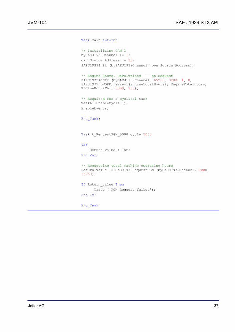
Jetter AG 137
JVM-104 SAE J1939 STX API
Task main autorun
// Initializing CAN 1 bySAEJ1939Channel := 1;
own_Source_Address := 20;
SAEJ1939Init (bySAEJ1939Channel, own_Source_Address);
// Engine Hours, Revolutions -- on Request SAEJ1939AddRx (bySAEJ1939Channel, 65253, 0x00, 1, 0, SAEJ1939_DWORD, sizeof(EngineTotalHours), EngineTotalHours, EngineHoursTbl, 5000, 150);
// Required for a cyclical task TaskAllEnableCycle ();
EnableEvents;
End_Task;
Task t_RequestPGN_5000 cycle 5000
Var
Return_value : Int;
End_Var;
// Requesting total machine operating hours Return_value := SAEJ1939RequestPGN (bySAEJ1939Channel, 0x00, 65253);
If Return_value Then
Trace ('PGN Request failed');
End_If;
End_Task;

138 Jetter AG
7 SAE J1939 STX API
STX function SAEJ1939GetDM1()
Calling up the function SAEJ1939GetDM1() requests the current diagnostics error codes (also see SAE J1939-73 No. 5.7.1). The corresponding PGN number is 65226. This function must constantly be recalled in cycles.
Function SAEJ1939GetDM1(
CANNo:Int,
bySA:Byte,
ref stJ1939DM1stat:TJ1939DM1STAT
ref stJ1939DM1msg:TJ1939DM1MSG
) :Int;
The function SAEJ1939GetDM1() comprises the following parameters:
Parameter Description Value
CANNo CAN channel number 1 ... CANMAX
bySA Source Address of message sender
0 ... 253 The own SA cannot be used
stJ1939DM1stat lStatus lMsgCnt lBuffer
Lamp status Number of received messages Size of variable stJ1939DM1msg
stJ1939DM1msg lSPN byOC byFMI
Error code Error counter Error type
This function transfers the following return values to the higher-level program.
Return value
0 OK
-1 Error when checking parameters
This parameter specifies the number of the SAEJ1939 interface. CANNo = 1 is assigned to the first interface. The number of SAEJ1939 interfaces depends on the device. For information on the maximum number of SAEJ1939 interfaces (CANMAX) refer to the chapters Technical Specifications and Quick Reference in the corresponding manual.
Introduction
Function declaration
Function parameters
Return value
CANNo parameter

Jetter AG 139
JVM-104 SAE J1939 STX API
Default: 0xFF00
Type Byte Bit group Description
Status 1 8 - 7 Malfunction Indicator Lamp Status
6 - 5 Red Stop Lamp Status
4 - 3 Amber Warning Lamp Status
2 - 1 Protect Lamp Status
Flash 2 8 - 7 Flash Malfunction Indicator Lamp
6 - 5 Flash Red Stop Lamp
4 - 3 Flash Amber Warning Lamp
2 - 1 Flash Protect Lamp
Type Byte Bit group Value
Description
Status 1 00 Lamps off
01 Lamps on
Flash 2 00 Slow Flash (1 Hz, 50 % duty cycle)
01 Fast Flash (2 Hz or faster, 50 % duty cycle)
10 Reserved
11 Unavailable / Do Not Flash
Default value: ISPN = 0 byOC = 0 byFMI = 0 For older controllers (grandfathered setting): ISPN = 524287 (0x7FFFF) byOC = 31 (0x1F) byFMI = 127 (0x7F)
Result := SAEJ1939GetDM1(
1,
0x00,
stdm1stat_pow,
stdm1msg_pow,);
stJ1939DM1stat.lStatus
stJ1939DM1msg
How to use this function

140 Jetter AG
7 SAE J1939 STX API
By calling up the function SAEJ1939GetDM1(), the JVM-104 requests the current diagnostics error code (PGN 65226). #Include "SAEJ1939.stxp"
Var
bySAEJ1939Channel : Byte;
own_Source_Address : Byte;
stdm1stat_pow : TJ1939DM1STAT;
stdm1msg_pow : Array[10] of STJ1939DM1MSG;
MyTimer : TTimer;
End_Var;
Task main autorun
// Initializing CAN 1 bySAEJ1939Channel := 1;
own_Source_Address := 20;
SAEJ1939Init (bySAEJ1939Channel, own_Source_Address);
TimerStart (MyTimer, T#2s);
Loop
When (TimerEnd (MyTimer)) Continue;
// Requesting diagnostics error codes DM1 POW stdm1stat_pow.lBuffer := sizeof (stdm1msg_pow);
SAEJ1939GetDM1 (bySAEJ1939Channel, 0x00, stdm1stat_pow, stdm1msg_pow);
TimerStart (MyTimer, T#2s);
End_Loop;
End_Task;
JetSym STX program
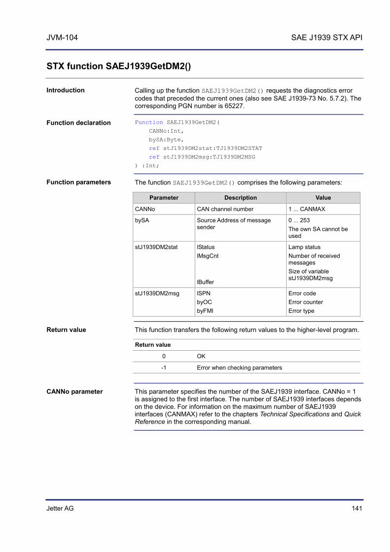
Jetter AG 141
JVM-104 SAE J1939 STX API
STX function SAEJ1939GetDM2()
Calling up the function SAEJ1939GetDM2() requests the diagnostics error codes that preceded the current ones (also see SAE J1939-73 No. 5.7.2). The corresponding PGN number is 65227.
Function SAEJ1939GetDM2(
CANNo:Int,
bySA:Byte,
ref stJ1939DM2stat:TJ1939DM2STAT
ref stJ1939DM2msg:TJ1939DM2MSG
) :Int;
The function SAEJ1939GetDM2() comprises the following parameters:
Parameter Description Value
CANNo CAN channel number 1 ... CANMAX
bySA Source Address of message sender
0 ... 253 The own SA cannot be used
stJ1939DM2stat lStatus lMsgCnt lBuffer
Lamp status Number of received messages Size of variable stJ1939DM2msg
stJ1939DM2msg lSPN byOC byFMI
Error code Error counter Error type
This function transfers the following return values to the higher-level program.
Return value
0 OK
-1 Error when checking parameters
This parameter specifies the number of the SAEJ1939 interface. CANNo = 1 is assigned to the first interface. The number of SAEJ1939 interfaces depends on the device. For information on the maximum number of SAEJ1939 interfaces (CANMAX) refer to the chapters Technical Specifications and Quick Reference in the corresponding manual.
Introduction
Function declaration
Function parameters
Return value
CANNo parameter
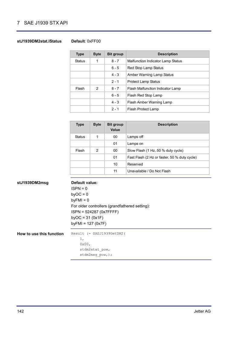
142 Jetter AG
7 SAE J1939 STX API
Default: 0xFF00
Type Byte Bit group Description
Status 1 8 - 7 Malfunction Indicator Lamp Status
6 - 5 Red Stop Lamp Status
4 - 3 Amber Warning Lamp Status
2 - 1 Protect Lamp Status
Flash 2 8 - 7 Flash Malfunction Indicator Lamp
6 - 5 Flash Red Stop Lamp
4 - 3 Flash Amber Warning Lamp
2 - 1 Flash Protect Lamp
Type Byte Bit group Value
Description
Status 1 00 Lamps off
01 Lamps on
Flash 2 00 Slow Flash (1 Hz, 50 % duty cycle)
01 Fast Flash (2 Hz or faster, 50 % duty cycle)
10 Reserved
11 Unavailable / Do Not Flash
Default value: ISPN = 0 byOC = 0 byFMI = 0 For older controllers (grandfathered setting): ISPN = 524287 (0x7FFFF) byOC = 31 (0x1F) byFMI = 127 (0x7F)
Result := SAEJ1939GetDM2(
1,
0x00,
stdm2stat_pow,
stdm2msg_pow,);
stJ1939DM2stat.lStatus
stJ1939DM2msg
How to use this function

Jetter AG 143
JVM-104 SAE J1939 STX API
By calling up the function SAEJ1939GetDM2(), the JVM-104 requests the current diagnostics error codes (PGN 65227). #Include "SAEJ1939.stxp"
Var
bySAEJ1939Channel : Byte;
own_Source_Address : Byte;
stdm2stat_pow : TJ1939DM2STAT;
stdm2msg_pow : Array[10] of STJ1939DM2MSG;
End_Var;
Task main autorun
// Initializing CAN 1 bySAEJ1939Channel := 1;
own_Source_Address := 20;
SAEJ1939Init (bySAEJ1939Channel, own_Source_Address);
// Required for a cyclical task TaskAllEnableCycle ();
EnableEvents;
End_Task;
Task t_RequestPGN_5000 cycle 5000
Var
Int;
End_Var;
// Requesting diagnostics error codes DM2 POW stdm2stat_pow.lBuffer := sizeof (stdm2msg_pow);
Return_value := SAEJ1939GetDM2 (bySAEJ1939Channel, 0x00, stdm2stat_pow, stdm2msg_pow);
If Return_value Then
Trace ('DM2 Request failed');
End_If;
End_Task;
JetSym STX program

144 Jetter AG
7 SAE J1939 STX API
STX function SAEJ1939SetSPNConversion()
Calling up the function SAEJ1939SetSPNConversion() determines the configuration of bytes in the message, which is requested using function SAEJ1939GetDM1() or SAEJ1939GetDM2(). In other words, this function lets you specify the conversion method.
Function SAEJ1939SetSPNConversion(
CANNo:Int,
bySA:Byte,
iConversionMethod:Int,
) :Int;
The function SAEJ1939SetSPNConversion() comprises the following parameters:
Parameter Description Value
CANNo CAN channel number 1 ... CANMAX
bySA Source Address of message sender
0 ... 253
iConversionMethod Conversion method 1 ... 4 4: Automatic detection 2: Default
This function transfers the following return values to the higher-level program.
Return value
0 OK
-1 Error when checking parameters
This parameter specifies the number of the SAEJ1939 interface. CANNo = 1 is assigned to the first interface. The number of SAEJ1939 interfaces depends on the device. For information on the maximum number of SAEJ1939 interfaces (CANMAX) refer to the chapters Technical Specifications and Quick Reference in the corresponding manual.
Result := SAEJ1939SetSPNConversion(
1,
0xAE,
4);
Introduction
Function declaration
Function parameters
Return value
CANNo parameter
How to use this function

Jetter AG 145
JVM-104 SAE J1939 STX API
STX Function SAEJ1939GetSPNConversion()
Calling up the function SAEJ1939GetSPNConversion() ascertains the currently set conversion method.
Function SAEJ1939SetSPNConversion(
CANNo:Int,
bySA:Byte,
iConversionMethod:Int,
) :Int;
The function SAEJ1939GetSPNConversion() comprises the following parameters:
Parameter Description Value
CANNo CAN channel number 1 ... CANMAX
bySA Source address of message sender
0 ... 253
iConversionMethod Conversion method 1 ... 4 4: Automatic detection 2: Default
This function transfers the following return values to the higher-level program.
Return value
0 OK
-1 Error when checking parameters
This parameter specifies the number of the SAEJ1939 interface. CANNo = 1 is assigned to the first interface. The number of SAEJ1939 interfaces depends on the device. For information on the maximum number of SAEJ1939 interfaces (CANMAX) refer to the chapters Technical Specifications and Quick Reference in the corresponding manual.
Result := SAEJ1939GetSPNConversion(
1,
0xAE,
actual_conversion_method);
Introduction
Function declaration
Function parameters
Return value
CANNo parameter
How to use this function

Jetter AG 147
JVM-104 File system
8 File system
This chapter describes the file system of the JVM-104. The file system lets you access files located on the internal flash disk or an USB flash drive. When problems occur, a good understanding of the file system is very helpful.
Exercise extreme caution when dealing with the file system, at least with system files. Failure to do so may render your device inoperative. It may even refuse to boot. Some files may be protected against read/write access or deletion. This is normal behavior. Some of these files are virtual files, such as firmware images, or protected files, such as EDS files.
The files of the file system are categorized as follows:
System directories or system files used by the operating system Files which are at the user's disposal
Topic Page Directories ................................................................................................... 148 Properties ................................................................................................... 152
Introduction
Note
File categories
Contents
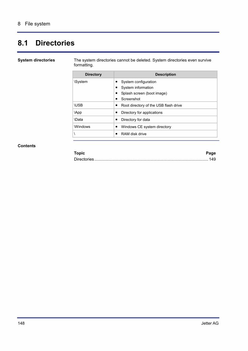
148 Jetter AG
8 File system
8.1 Directories
The system directories cannot be deleted. System directories even survive formatting.
Directory Description
\System System configuration System information Splash screen (boot image) Screenshot
\USB Root directory of the USB flash drive
\App Directory for applications
\Data Directory for data
\Windows Windows CE system directory
\ RAM disk drive
Topic Page Directories ................................................................................................... 149
System directories
Contents
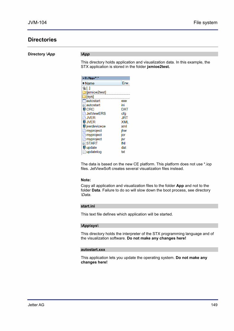
Jetter AG 149
JVM-104 File system
Directories
\App
This directory holds application and visualization data. In this example, the STX application is stored in the folder jxmioe2test.
The data is based on the new CE platform. This platform does not use *.iop files. JetViewSoft creates several visualization files instead. Note: Copy all application and visualization files to the folder App and not to the folder Data. Failure to do so will slow down the boot process, see directory \Data. start.ini
This text file defines which application will be started. \App\sys\
This directory holds the interpreter of the STX programming language and of the visualization software. Do not make any changes here! autostart.xxx
This application lets you update the operating system. Do not make any changes here!
Directory \App
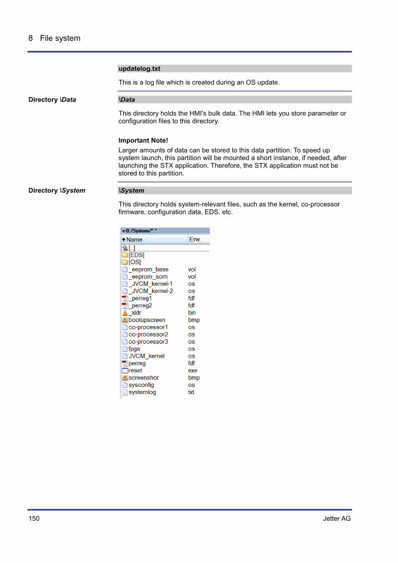
150 Jetter AG
8 File system
updatelog.txt
This is a log file which is created during an OS update.
\Data
This directory holds the HMI's bulk data. The HMI lets you store parameter or configuration files to this directory. Important Note! Larger amounts of data can be stored to this data partition. To speed up system launch, this partition will be mounted a short instance, if needed, after launching the STX application. Therefore, the STX application must not be stored to this partition.
\System
This directory holds system-relevant files, such as the kernel, co-processor firmware, configuration data, EDS, etc.
Directory \Data
Directory \System

Jetter AG 151
JVM-104 File system
bootupscreen.bmp
This file is a 16-bit bmp file (r5, g6, b5) which is displayed while the device is booting. You may create an image of your own and replace this file. co-processor1
This virtual file holds the firmware of a hidden co-processor controlling most of the interactions with the user (buttons, buzzer, background lighting, etc.). reset.exe
If you delete this file, the HMI reboots immediately. You can use this function in batch files, for example, which, after complete processing, require automatic rebooting.
\USB
When you insert a USB flash drive into the HMI, a dynamic directory named \USB is created. When no data storage medium is inserted, this directory is not visible.
\Windows
This subdirectory holds the Windows CE files. Do not make any changes here!
Directory \USB
Directory \Windows

152 Jetter AG
8 File system
8.2 Properties
This chapter covers the properties of the file system. The description distinguishes between the internal flash disk and the USB flash drive.
The following properties apply to the internal flash disk and USB flash drive:
8 files max. to be opened simultaneously When the HMI creates a file, it assigns its date and time. Date, time, and file size are not available for all system files.
Topic Page Flash disk - Properties ................................................................................ 153 USB flash drive - Properties ....................................................................... 154
Introduction
General properties
Contents

Jetter AG 153
JVM-104 File system
Flash disk - Properties
The following disk space is available to the user:
Parameter Value
Flash disk capacity 512 MBytes
Size of folder App (of the a.m. capacity) 64 MBytes
Size of folder Data (of the a.m. capacity) 368 MBytes
The internal flash disk drive has got the following further properties:
Up to 7 directory levels and 1 file level are allowed. Upper- and lower-case are not distinguished. Directory and file names are permitted to have a total length of
63 characters. All characters except "/" and ".." are permitted for directory and file names The location of the folders App and Data is on the flash disk drive.
Capacity
Properties

154 Jetter AG
8 File system
USB flash drive - Properties
The available capacity depends on the USB flash drive used:
Parameter Value
Tested capacities 256 MByte ... 8 GByte
The USB flash drive has got the following properties:
The USB flash drive must be compatible with FAT 16 or FAT 32. Directory and file names of 260 characters' length max. can be used. Differentiation between upper and lower case. The following characters are not allowed in directory and file names: "/", "\",
":", "*", "?", "<", ">" and "|" There is no user/access administration. Jetter AG cannot guarantee the proper functioning of all USB flash drives available on the market.
Capacity
Properties
Jetter AG 155
JVM-104 FTP server
9 FTP server
The FTP server allows access to directories and files using an FTP client. The files can be stored to the following storage media:
Internal flash disk USB flash drive This chapter covers the login process and describes the commands supported by the FTP server.
The user has the option of using a command line FTP client, which comes with many PC operating systems, or graphic FTP tools.
The FTP server on the JVM-104 is able to manage up to four FTP connections simultaneously. Any additional FTP client, which tries to connect with the FTP server, will get no response to its request for establishing a connection.
The FTP server supports standardized commands. For more information refer to:
WIKIPEDIA Google; search for FTP and commands FTP server help menu; connect with FTP server and enter the command
help or help binary. If you do not wish to care about commands, use an FTP program, such as TotalCmd.
To be able to use the functions described in this chapter, the programmer must be familiar with the following subjects:
The file system of the controller IP networks Commands
Topic Page Logon .......................................................................................................... 156 Example: Windows FTP client .................................................................... 157
Introduction
FTP clients
Number of possible connections
Supported commands
Required programmer's skills
Contents

156 Jetter AG
9 FTP server
Logon
To be able to access the file system via FTP, the FTP client must log on when the connection is established.
As Server Name enter the IP address of the device. As User Name enter your user name, e.g. admin. As Password enter your password, e.g. admin.
The factory settings of the JVM-104 include one user account:
NAME=admin PW=admin
Logon
Factory settings
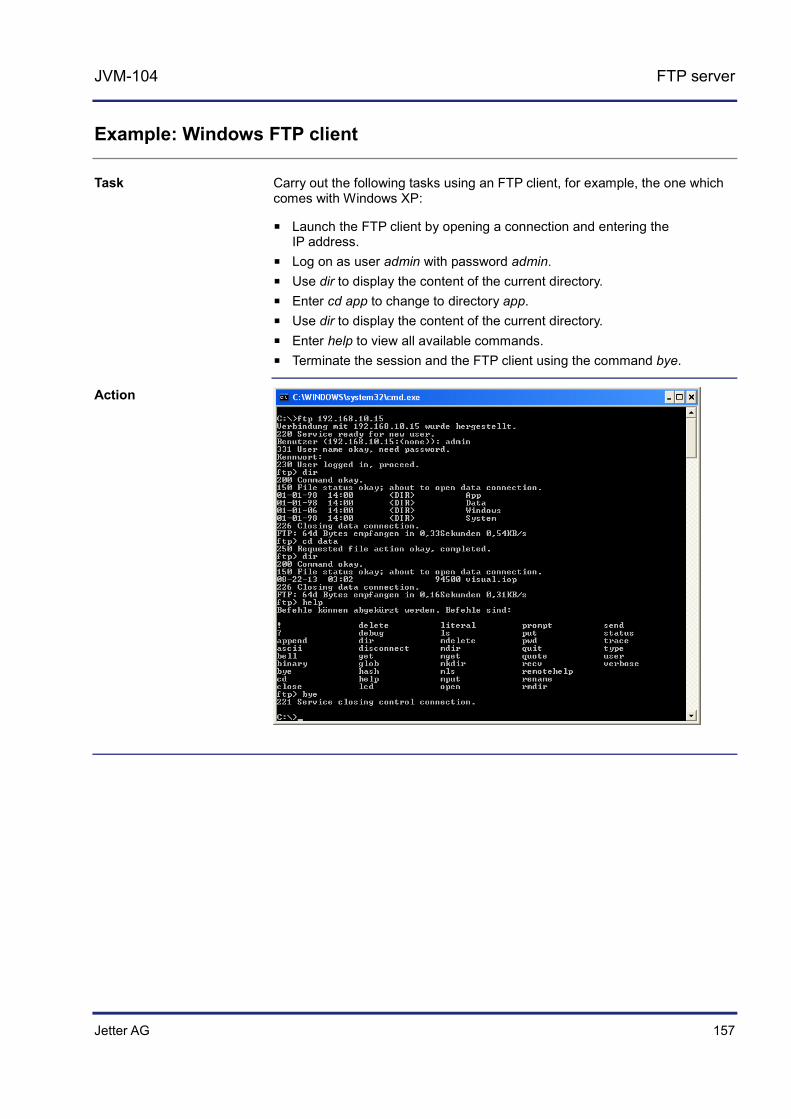
Jetter AG 157
JVM-104 FTP server
Example: Windows FTP client
Carry out the following tasks using an FTP client, for example, the one which comes with Windows XP:
Launch the FTP client by opening a connection and entering the IP address.
Log on as user admin with password admin. Use dir to display the content of the current directory. Enter cd app to change to directory app. Use dir to display the content of the current directory. Enter help to view all available commands. Terminate the session and the FTP client using the command bye.
Task
Action

Jetter AG 159
JVM-104 Programming
10 Programming
This chapter is for supporting you in programming the HMI JVM-104 in the following fields of activity:
Programming additional functions
To be able to program the HMI JVM-104 the following prerequisites must be fulfilled:
The HMI is connected to a PC. On the PC, the JetSym programming software has been installed.
Topic Page Abbreviations, module register properties and formats .............................. 160 Memories - Overview .................................................................................. 161 Controls and ignition ................................................................................... 172 Multi-purpose inputs/outputs ...................................................................... 179 Runtime registers........................................................................................ 196 Monitoring interface activities ..................................................................... 201 User-programmable IP interface ................................................................ 206
Purpose of this chapter
Prerequisites
Contents
160 Jetter AG
10 Programming
Abbreviations, module register properties and formats
The abbreviations used in this document are listed in the table below:
Abbreviation Description
R 100 Register 100
MR 150 Module register 150
Each module register is characterized by certain properties. Most properties are identical for many module registers - the value after reset is always zero, for example. In the following description, module register properties are mentioned only if a property deviates from the following default properties.
Module register properties Default property for most module registers
Access Read/write
Value after reset 0 or undefined (e.g. release number)
Takes effect Immediately
Write access Always
Data type Integer
The numerical formats used in this document are listed in the table below:
Notation Numerical format
100 Decimal
0x100 Hexadecimal
0b100 Binary
The notation for sample programs used in this document is listed in the table below:
Notation Description Var, When, Task Keyword BitClear(); Commands 100 0x100 0b100 Constant numerical values
// This is a comment Comment
// ... Further program processing
Abbreviations
Module register properties
Numerical formats
JetSym sample programs
Jetter AG 161
JVM-104 Programming
10.1 Memories - Overview
The JVM-104 features several types of program and data memories. There is, for example, volatile memory. Volatile memory loses its content at switching off. Non-volatile memory keeps its content even when the power supply is off. This chapter gives an overview of the available memory.
Topic Page Operating system memory ......................................................................... 162 File system memory ................................................................................... 163 Application program memory ...................................................................... 164 Memory for volatile application program variables ..................................... 165 Memory for non-volatile application program registers .............................. 166 Memory for non-volatile application program variables .............................. 167 Special registers ......................................................................................... 169 Flags ........................................................................................................... 170
Introduction
Contents

162 Jetter AG
10 Programming
Operating system memory
The OS is stored to a non-volatile flash memory in the CPU. Therefore, the OS can be executed immediately after the device is powered up.
Internal flash memory for storing OS data Internal volatile RAM for storing OS data
The user is not allowed to directly access the OS memory. To modify the OS, it must be updated.
OS update (see page 248)
Introduction
Properties
Memory access
Related topics

Jetter AG 163
JVM-104 Programming
File system memory
The file system memory is for storing data and program files.
Non-volatile Internal flash disk size: 368 MBytes Size of the USB flash drive: 256 MByte to 8 GByte
By operating system By JetSym Via FTP connection By browser (via HTTP server) By means of file commands from within the application program
Introduction
Properties
Memory access

164 Jetter AG
10 Programming
Application program memory
By default, the application program (STX script) is uploaded from JetSym to the HMI and is stored to it.
Stored as file within the file system Default directory \app\program name Files may also be stored to other directories (or USB flash drive)
By operating system By JetSym Via FTP connection By means of file commands from within the application program
Application program (see page 257)
Introduction
Properties
Memory access
Related topics
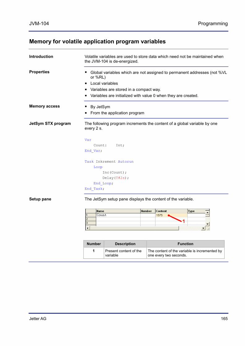
Jetter AG 165
JVM-104 Programming
Memory for volatile application program variables
Volatile variables are used to store data which need not be maintained when the JVM-104 is de-energized.
Global variables which are not assigned to permanent addresses (not %VL or %RL)
Local variables Variables are stored in a compact way. Variables are initialized with value 0 when they are created.
By JetSym From the application program
The following program increments the content of a global variable by one every 2 s. Var
Count: Int;
End_Var;
Task Inkrement Autorun
Loop
Inc(Count);
Delay(T#2s);
End_Loop;
End_Task;
The JetSym setup pane displays the content of the variable.
Number Description Function
1 Present content of the variable
The content of the variable is incremented by one every two seconds.
Introduction
Properties
Memory access
JetSym STX program
Setup pane

166 Jetter AG
10 Programming
Memory for non-volatile application program registers
Non-volatile registers are used to store data which must be maintained when the JVM-104 is de-energized.
Global variables which are assigned to permanent addresses (%VL) Register variables always occupy 4 bytes. Register variables are not initialized by the operating system. Number of register variables: 30,000 Register numbers: 1000000 ... 1029999
By JetSym By browser (via HTTP server) From HMIs From the application program From other controllers
The following program increments the content of a register variable every time the application program is started. This way, the number of program starts is counted. Var
ProgramStartCounter: Int At %VL 1000000;
End_Var;
Task Work Autorun
ProgramStartCounter := ProgramStartCounter + 1;
Loop
// ... End_Loop;
End_Task;
The JetSym setup pane displays the content of the register variable.
Number Description Function
1 Present content of the register variable
The content of the register variable is incremented by one every time the program is started.
Introduction
Properties
Memory access
JetSym STX program
Setup pane
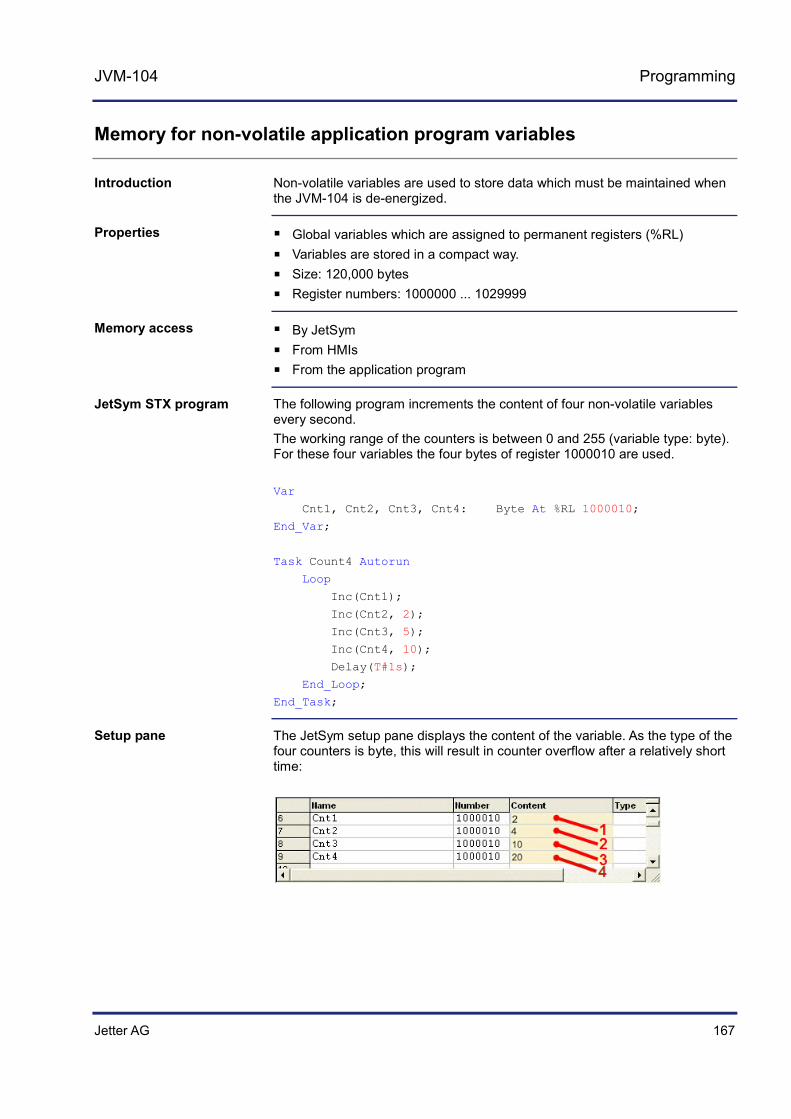
Jetter AG 167
JVM-104 Programming
Memory for non-volatile application program variables
Non-volatile variables are used to store data which must be maintained when the JVM-104 is de-energized.
Global variables which are assigned to permanent registers (%RL) Variables are stored in a compact way. Size: 120,000 bytes Register numbers: 1000000 ... 1029999
By JetSym From HMIs From the application program
The following program increments the content of four non-volatile variables every second. The working range of the counters is between 0 and 255 (variable type: byte). For these four variables the four bytes of register 1000010 are used. Var
Cnt1, Cnt2, Cnt3, Cnt4: Byte At %RL 1000010;
End_Var;
Task Count4 Autorun
Loop
Inc(Cnt1);
Inc(Cnt2, 2);
Inc(Cnt3, 5);
Inc(Cnt4, 10);
Delay(T#1s);
End_Loop;
End_Task;
The JetSym setup pane displays the content of the variable. As the type of the four counters is byte, this will result in counter overflow after a relatively short time:
Introduction
Properties
Memory access
JetSym STX program
Setup pane

168 Jetter AG
10 Programming
Number Description Function
1 Current content of the variable Cnt1
The content of the variable is incremented by one every second.
2 Current content of the variable Cnt2
The content of the variable is incremented by two every second.
3 Current content of the variable Cnt3
The content of the variable is incremented by five every second.
4 Current content of the variable Cnt4
The content of the variable is incremented by ten every second.
Jetter AG 169
JVM-104 Programming
Special registers
Special registers let you control OS functions and retrieve status information.
Global variables which are assigned to permanent addresses (%VL) When the operating system is launched, special registers are initialized
using default values. Register numbers: 100000 ... 999999
By JetSym By browser (via HTTP server) From HMIs From the application program From other controllers
The following program uses the special register to store the digipot value. In this program, the background lighting for the JVM-104 is dimmed by using the digipot. An upper and lower limit for the digipot is specified for this purpose. If you press the pushbutton, full background lighting is activated. Var
Digipot_Count : Int At %VL 363000;
Digipot_Limit_min: Int At %VL 363002;
Digipot_Limit_max: Int At %VL 363003;
Digipot_Button : Int At %VL 363001;
BackgroundLighting: Int At %VL 364000;
End_Var;
Task Main Autorun
Digipot_Count := 0;
Digipot_Limit_max := 17;
Digipot_Limit_min := 0;
Loop
If Digipot_Button Then
BackgroundLighting := 255;
Else BackgroundLighting := Digipot_Count * 15;
End_If
End_Loop
End_Task;
Introduction
Properties
Memory access
JetSym STX program

170 Jetter AG
10 Programming
Flags
Flags are one-bit operands. This means they can either have the value TRUE or FALSE.
Global variables which are assigned to permanent addresses (%MX) Non-volatile Quantity: 256 Flag numbers: 0 ... 255
Global variables which are assigned to permanent addresses (%MX) Non-volatile Overlaid by registers 1000000 through 1000055 Quantity: 1,792 Flag numbers: 256 ... 2047
Global variables which are assigned to permanent addresses (%MX) When the operating system is launched, special flags are initialized using
their default values. Quantity: 256 Flag numbers: 2048 ... 2303
By JetSym From HMIs From the application program
In the program listed below, a flag is set when the user presses KEY_UP. If KEY_DOWN is pressed, the flag is reset. As long as this flag is set, special register 364000 (background lighting) is incremented. Incrementing of the special register continues until the flag is reset. Var
Flag1: Bool At %MX 1;
Key_Up: Bit At %XL 361000.3;
Key_Down: Bit At %XL 361000.2;
Background_Light: Int At %VL 364000;
End_Var;
Task Main Autorun
Flag1:= False;
Loop
If Key_Up Then
Flag1 := True;
ElseIf Key_Down Then
Flag1 := False;
End_IF;
Introduction
Properties of user flags
Properties of overlaid user flags
Properties of special flags
Memory access
JetSym STX program

Jetter AG 171
JVM-104 Programming
If Flag1 Then
Inc(Background_Light);
Delay(T#100ms);
End_If;
End_Loop;
End_Task;

172 Jetter AG
10 Programming
10.2 Controls and ignition
This chapter covers the programming of controls, ignition and switching off delay for the JVM-104.
Topic Page Input keys .................................................................................................... 173 Digipot ......................................................................................................... 175 Ignition and shutdown delay ....................................................................... 177
Introduction
Contents
Jetter AG 173
JVM-104 Programming
Input keys
The HMI JVM-104 has got four input keys: [UP], [DOWN], [OK] and [ESC]. These input keys are user-programmable.
In register 361000 of the JVM-104, there is a bit-coded map of the input keys which can be used for programming them. The following registers are available for programming these input keys:
Register Description
361000 Bit-coded map of the input keys
361000.0 Input key [OK] Bit 0 = 1: Key [OK] is pressed.
361000.1 Input key [ESC] Bit 1 = 1: Key [ESC] is pressed.
361000.2 Input key [DOWN] Bit 2 = 1: Key [DOWN] is pressed.
361000.3 Input key [UP] Bit 3 = 1: Key [UP] is pressed.
The sample program has been tested for compliance with the following software versions:
JetSym version 5.2 HMI JVM-104, OS version 4.01 For more information on programming by STX, please turn to the online help in JetSym.
Description: In the following sample program, the input keys are continuously retrieved in one task. Pressing one or more keys changes the background lighting of the display or the night lighting of the keys.
Var
btnKey_Ok: Bit At %XL 361000.0;
btnKey_Esc: Bit At %XL 361000.1;
btnKey_Dwn: Bit At %XL 361000.2;
btnKey_Up: Bit At %XL 361000.3;
dispBackLed : Int At %VL 364000;
dispButtonBackLed : Int At %VL 364001;
End_Var;
Introduction
Special registers
Software versions
JetSym STX program

174 Jetter AG
10 Programming
Task Main Autorun
Loop
If btnKey_Up Then
// Half brightness of background lighting dispBackLed := 127;
End_If;
If btnKey_Dwn Then
// Full brightness of background lighting dispBackLed := 255;
End_If;
If btnKey_Esc Then
// Full brightness of night key lighting dispButtonBackLed := 255;
End_If;
If btnKey_Ok Then
// Turn off night lighting of the keys dispButtonBackLed := 0;
End_If;
Delay(T#100ms);
End_Loop;
End_Task;

Jetter AG 175
JVM-104 Programming
Digipot
The JVM-104 has a digipot with pushbutton feature, which offers a convenient input option. The following provides details of the digipot's special registers with a corresponding sample program.
The following special registers exist for the digipot:
Register Description
363000 This register holds the current count value. If you turn the digipot, the count value increments or decrements. The following rule applies:
Turning the digipot clockwise = incrementing the register Turning the digipot counter-clockwise = decrementing the register
363001 Bit 0: 0 = Pusbutton not pressed Bit 0: 1 = Pusbutton pressed
363002 This register lets you specify the lower limit for the digipot reading. If you continue turning the digipot counter-clockwise, register 363000 remains at this minimum value.
363003 This register lets you specify the upper limit for the digipot reading. If you continue turning the digipot clockwise, register 363000 remains at this maximum value.
The sample program has been tested for compliance with the following software versions:
JetSym version 5.2 HMI JVM-104, OS version 4.01 For more information on programming by STX, please turn to the online help in JetSym.
In the following sample program, the background lighting for the JVM-104 is dimmed using the digipot. An upper and lower limit for the digipot is specified for this purpose. If you press the pushbutton, full background lighting is activated.
Var
Digipot_Count : Int At %VL 363000;
Digipot_Limit_min: Int At %VL 363002;
Digipot_Limit_max: Int At %VL 363003;
Digipot_Button : Int At %VL 363001;
BackgroundLighting: Int At %VL 364000;
End_Var;
Task Main Autorun
Digipot_Count := 0;
Digipot_Limit_max := 17;
Digipot_Limit_min := 0;
Introduction
Digipot registers
Software versions
JetSym STX program

176 Jetter AG
10 Programming
Loop
If Digipot_Button Then
BackgroundLighting := 255;
Else BackgroundLighting := Digipot_Count * 15;
End_If
End_Loop
End_Task;
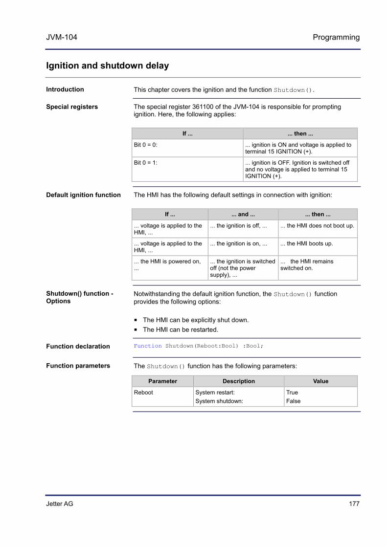
Jetter AG 177
JVM-104 Programming
Ignition and shutdown delay
This chapter covers the ignition and the function Shutdown().
The special register 361100 of the JVM-104 is responsible for prompting ignition. Here, the following applies:
If ... ... then ...
Bit 0 = 0: ... ignition is ON and voltage is applied to terminal 15 IGNITION (+).
Bit 0 = 1: ... ignition is OFF. Ignition is switched off and no voltage is applied to terminal 15 IGNITION (+).
The HMI has the following default settings in connection with ignition:
If ... ... and ... ... then ...
... voltage is applied to the HMI, ...
... the ignition is off, ... ... the HMI does not boot up.
... voltage is applied to the HMI, ...
... the ignition is on, ... ... the HMI boots up.
... the HMI is powered on,
... ... the ignition is switched off (not the power supply), ...
... the HMI remains switched on.
Notwithstanding the default ignition function, the Shutdown() function provides the following options:
The HMI can be explicitly shut down. The HMI can be restarted.
Function Shutdown(Reboot:Bool) :Bool;
The Shutdown() function has the following parameters:
Parameter Description Value
Reboot System restart: System shutdown:
True False
Introduction
Special registers
Default ignition function
Shutdown() function - Options
Function declaration
Function parameters

178 Jetter AG
10 Programming
This function transmits the following return values to the higher-level program.
Return value
0 OK
-1 Ignition is still switched on
If the ignition is still switched on, the device will not be switched off. However, the HMI can be restarted. Such a restart is carried out irrespective of the fact that the ignition is on.
The sample program has been tested for compliance with the following software versions:
JetSym version 5.2 HMI JVM-104, OS version 4.01 For more information on programming by STX, please turn to the online help in JetSym.
If you switch off the vehicle's ignition, in the sample program the function Shutdown() is carried out after a delay of 3 seconds. The Reboot parameter for the Shutdown() function has the value false. This means that the device will switch off. Var
Ignition: Int At %VL 361100;
End_Var;
Task Ign Autorun
Loop
When Ignition Continue;
Delay(3000);
Shutdown(False);
End_Loop;
End_Task;
Return value
Note
Software versions
JetSym STX program

Jetter AG 179
JVM-104 Programming
10.3 Multi-purpose inputs/outputs
This chapter covers programming the multi-purpose inputs and outputs of the JVM-104. The special registers of the HMI have got the functions listed below:
Programming multi-purpose inputs Programming multi-purpose outputs Retrieving the hardware and software version for I/O functions
Topic Page Multi-purpose inputs - Status and commands ............................................ 180 Multi-purpose inputs - Analog functions...................................................... 182 Multi-purpose inputs - Digital functions ....................................................... 185 Multi-purpose outputs - Status and commands .......................................... 188 Multi-purpose outputs - Analog functions ................................................... 190 Multi-purpose outputs - Digital functions .................................................... 192 Multi-purpose outputs PA3 and PA4 functioning as H-bridges ................... 194
Introduction
Contents

180 Jetter AG
10 Programming
Multi-purpose inputs - Status and commands
The table below lists the functions of the multi-purpose inputs:
Voltage measuring Current measuring Digital active-high input Frequency measuring Counting mode
Placeholder x is for clearer representation. The table below shows how placeholders are used to address individual inputs. Throughout this chapter the following rules apply:
Placeholder Value Description
x 1 Multi-purpose input MFQE1
x 2 Multi-purpose input MFQE2
Example x = 2 for multi-purpose output 2. The overtemperature is given in R 601020000.7.
Each of the multi-purpose inputs MFQE1 and MFQE2 has got the following registers:
Register Description
6010x0000 Status (bit-coded)
6010x0001 Command (bit-coded)
6010x0002 Analog value in µA/mV
6010x0003 Frequency [gate time]/period [µs]/count value [increments]
6010x0004 Digital value of the active-high input
6010x0005 Gate time in ms within frequency metering
Status register of the multi-purpose input MFQEx
R 6010x0000 shows the status of the multi-purpose input MFQEx.
Meaning of the individual bits
Bit 0 Overcurrent
1 = Triggered by a current > 2500 mA.
Introduction
Placeholder x
Register overview - Multi-purpose inputs
R6010x0000
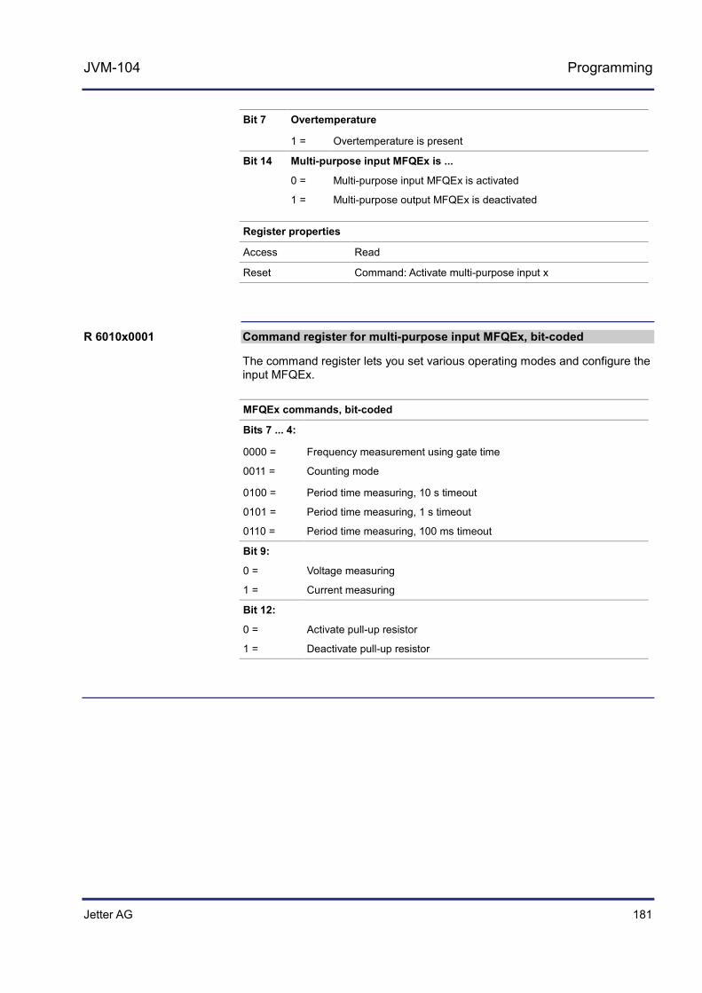
Jetter AG 181
JVM-104 Programming
Bit 7 Overtemperature
1 = Overtemperature is present
Bit 14 Multi-purpose input MFQEx is ...
0 = Multi-purpose input MFQEx is activated
1 = Multi-purpose output MFQEx is deactivated
Register properties
Access Read
Reset Command: Activate multi-purpose input x
Command register for multi-purpose input MFQEx, bit-coded
The command register lets you set various operating modes and configure the input MFQEx.
MFQEx commands, bit-coded
Bits 7 ... 4:
0000 = Frequency measurement using gate time
0011 = Counting mode
0100 = Period time measuring, 10 s timeout
0101 = Period time measuring, 1 s timeout
0110 = Period time measuring, 100 ms timeout
Bit 9:
0 = Voltage measuring
1 = Current measuring
Bit 12:
0 = Activate pull-up resistor
1 = Deactivate pull-up resistor
R 6010x0001
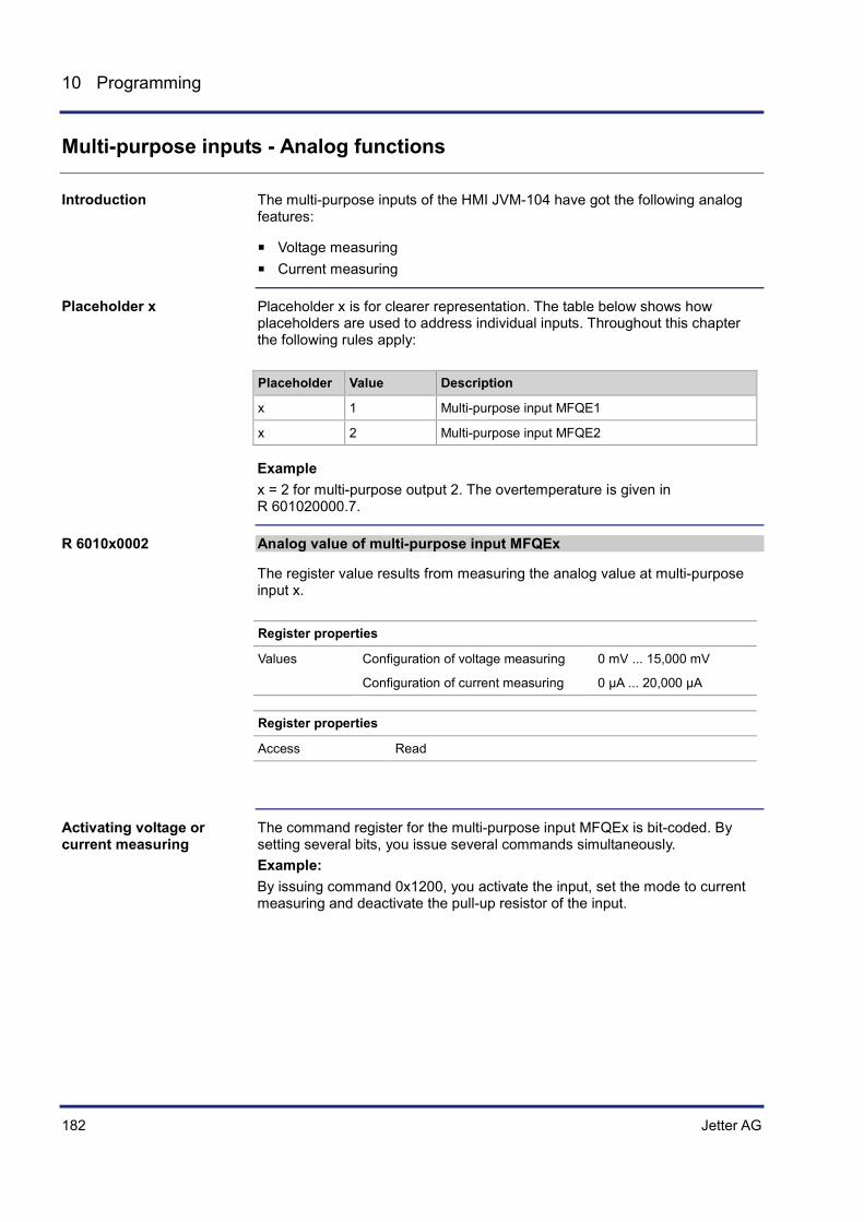
182 Jetter AG
10 Programming
Multi-purpose inputs - Analog functions
The multi-purpose inputs of the HMI JVM-104 have got the following analog features:
Voltage measuring Current measuring
Placeholder x is for clearer representation. The table below shows how placeholders are used to address individual inputs. Throughout this chapter the following rules apply:
Placeholder Value Description
x 1 Multi-purpose input MFQE1
x 2 Multi-purpose input MFQE2
Example x = 2 for multi-purpose output 2. The overtemperature is given in R 601020000.7.
Analog value of multi-purpose input MFQEx
The register value results from measuring the analog value at multi-purpose input x.
Register properties
Values Configuration of voltage measuring 0 mV ... 15,000 mV
Configuration of current measuring 0 µA ... 20,000 µA
Register properties
Access Read
The command register for the multi-purpose input MFQEx is bit-coded. By setting several bits, you issue several commands simultaneously. Example: By issuing command 0x1200, you activate the input, set the mode to current measuring and deactivate the pull-up resistor of the input.
Introduction
Placeholder x
R 6010x0002
Activating voltage or current measuring

Jetter AG 183
JVM-104 Programming
You can activate voltage or current measuring for multi-purpose input MFQEx as follows:
Step Action
1 Activate the input: To this end, enter value 0 into R 6010x0001.
2 You can activate a pull-up resistor at the input.
If ... ... then ...
... you want to activate the pull-up resistor,
... clear bit 12: BitClear(R 6010x0001, 12);
... you want to deactivate the pull-up resistor,
... set bit 12: BitClear(R 6010x0001, 12);
3 Select the measuring mode:
If ... ... then ...
... you want to measure a voltage, ... clear bit 9: BitClear(R 6010x0001, 9);
... you want to measure a current, ... set bit 9: BitClear(R 6010x0001, 9);
If you activate the HMI, the multi-purpose input MFQEx is active, too.
The sample program has been tested for compliance with the following software versions:
JetSym version 5.2 HMI JVM-104, OS version 4.01 For more information on programming by STX, please turn to the online help in JetSym.
The following example explains how to make use of the multi-purpose input MFQE1 for voltage measuring and the multi-purpose input MFQE2 for current measuring. Var
// MFQE1: Input 1 MFQE1_Command: Int At %VL 601010001;
MFQE1_Value: Int At %VL 601010002;
// MFQE2: Input 2 MFQE2_Command: Int At %VL 601020001;
MFQE2_Value: Int At %VL 601020002;
End_Var;
Task Main Autorun
// Activate input MFQE1 MFQE1_Command := 0;
// Input MFQE1 in voltage measuring mode BitClear(MFQE1_Command, 9);
Note
Software versions
JetSym STX program

184 Jetter AG
10 Programming
// Activate input MFQE2 MFQE2_Command := 0;
// Input MFQE2 in current measuring mode BitSet(MFQE2_Command, 9);
Loop
Trace('Voltage value at MFQE1 ' + IntToStr(MFQE1_Value) + ' mV.$n');
Trace('Current value at MFQE2 ' + IntToStr(MFQE2_Value) + ' mA.$n');
Delay(T#100ms);
End_Loop;
End_Task;

Jetter AG 185
JVM-104 Programming
Multi-purpose inputs - Digital functions
The multi-purpose inputs of the HMI JVM-104 have got the following digital features:
Digital input Frequency measurement Counting mode
Placeholder x is for clearer representation. The table below shows how placeholders are used to address individual inputs. Throughout this chapter the following rules apply:
Placeholder Value Description
x 1 Multi-purpose input MFQE1
x 2 Multi-purpose input MFQE2
Example x = 2 for multi-purpose output 2. The overtemperature is given in R 601020000.7.
Frequency value of multi-purpose input MFQEx
Depending on the configuration, this register displays the frequency, the period or a count value of the multi-purpose input x.
Register properties
Values Configuration of frequency measuring 0.1 Hz ... 10 kHz
Configuration of period time measuring 10 s ... 100 ms
Configuration of increment counting 32 bits
Register properties
Access Read
Digital value at multi-purpose input MDQEx
The register value results from measuring the digital value at multi-purpose input x. The digital input is an active-high input.
Register properties
Values Input x < 1.0 V Low-level
Input x > 2.0 V High-level
Introduction
Placeholder x
R 6010x0003
R 6010x0004

186 Jetter AG
10 Programming
Gate time for frequency measuring at input MFQEx
The register value lets you set a gate time for frequency measuring. For frequency measuring, set a gate time unequal zero.
Register properties
Values 100 ms ... 10 s
Value after reset 1,000 (1 s) 0: Deactivated
The command register for the multi-purpose input MFQEx is bit-coded. By setting several bits, you can issue several commands simultaneously. You can activate frequency or period measuring or the counting function for multi-purpose input MFQEx as follows:
Step Action
1 Activate the input: To this end, enter value 0 into R 6010x0001.
If ... ... then ...
... you want to measure a frequency with gate time,
... write as gate time a value unequal zero to R 6010x0005. Activate frequency measuring by writing value 0x0040 to R 6010x0001,
... you want to count increments, ... write value 0x0030 to R 601x0001.
... you want to measure a period, ... write value 0x0040 to R 601x0001.
The result is contained in R 6010x0003.
The sample program has been tested for compliance with the following software versions:
JetSym version 5.2 HMI JVM-104, OS version 4.01 For more information on programming by STX, please turn to the online help in JetSym.
R 6010x0005
Activating frequency/period measuring or counter function
Software versions

Jetter AG 187
JVM-104 Programming
The following example explains how to make use of the multi-purpose input MFQE1 for increment measuring and of MFQE2 for frequency measuring with gate time. Var
// MFQE1: Input 1 MFQE1_Command: Int At %VL 601010001;
MFQE1_Freq: Int At %VL 601010003;
// MFQE2: Input 2 MFQE2_Command: Int At %VL 601020001;
MFQE2_Freq: Int At %VL 601020003;
MFQE2_GateTime: Int At %VL 601020005;
End_Var;
Task Main Autorun
// Activating measuring of increments at MFQE1: MFQE1_Command := 0x0030;
// Measuring a frequency at MFQE2 MFQE2_Command := 0x0040;
// Setting a gate time of 1 s at MFQE2: MFQE2_GateTime := 1000;
Loop
// Issuing values Trace('Inkrements: ' + InttoStr(MFQE1_Freq) + '$n');
Trace('frequency in Hertz: : ' + InttoStr(MFQE2_Freq) + '$n');
Delay(T#300ms);
End_Loop;
End_Task;
JetSym STX program

188 Jetter AG
10 Programming
Multi-purpose outputs - Status and commands
The table below lists the functions of the multi-purpose outputs:
Current measuring Digital output, adjustable as high-side or low-side output Output of PWM signals Operation as H-bridge
Placeholder x is for clearer representation. The table below shows how placeholders are used to address individual outputs. Throughout this chapter the following rules apply:
Placeholder Value Description
x 5 Multi-purpose output PA3
x 6 Multi-purpose output PA4
Example: x = 5 for multi-purpose output PA3. To activate the digital output of PA3 enter command 0x0008 into R 601050001.
Each of the multi-purpose outputs PA3 and PA4 has got the following registers:
Register Description
6010x0000 Status (bit-coded)
6010x0001 Command (bit-coded)
6010x0002 PWM pulse control factor (duty cycle) in steps of 0.1 %
6010x0005 Measured current of output PAx in mA
6010x0006 PWM frequency in Hz
6010x0007 Adjustable overcurrent limit in mA
Status register of the multi-purpose outputs PA3 and PA4
In R 6010x0000 the HMI reports the status of multi-purpose outputs PA3 and PA4.
Meaning of the individual bits
Bit 0 Overcurrent of H-side
1 = Overcurrent detection has tripped
Introduction
Placeholder x
Register overview - Multi-purpose outputs
R6010x0000

Jetter AG 189
JVM-104 Programming
Bit 3 Short circuit, L-side
1 = Overcurrent detection has tripped
Bit 6 Cable breakage (open load)
1 = A cable breakage is present
Bit 7 Overtemperature
1 = Overtemperature is present
Bit 14 Multi-purpose output is ...
0 = Multi-purpose output PAx is active
1 = Multi-purpose output PAx is deactivated
Bit 15 Hardware protection has tripped
1 = Hardware protection has tripped due to overcurrent/short circuit
Register properties
Access Read
Reset Command: Activate multi-purpose output x
Value after reset 0x00000040 (if no device has been connected)
Command register for multi-purpose outputs PA3 and PA4, bit-coded
The command register lets you set various operating modes and configure the respective PAx output.
PAx commands, bit-coded
Bit 1 ... 0 Operating mode of the output
00 = Output PAx as digital output
01 = Output PAx as PWM output
Bits 3 ... 2:
00 = Output PAx as input
01 = Output PAx as low-side output
10 = Output PAx as high-side output
11 = Output PAx as low-side output
Bit 15:
0 = Activate output
1 = Deactivate output
R 6010x0001

190 Jetter AG
10 Programming
Multi-purpose outputs - Analog functions
The multi-purpose outputs of the HMI JVM-104 have got the following analog features:
Current measuring Setting the limit of the overcurrent
Placeholder x is for clearer representation. The table below shows how placeholders are used to address individual outputs. Throughout this chapter the following rules apply:
Placeholder Value Description
x 5 Multi-purpose output PA3
x 6 Multi-purpose output PA4
Example: x = 5 for multi-purpose output PA3. To activate the digital output of PA3 enter command 0x0008 into R 601050001.
Measured current PAx in mA
This register displays the current measured at output PAx in mA. This current measuring is only valid, if PAx is configured as output.
Register properties
Values 0 ... 2,300
Unit Milliampere
Register properties
Access Read
Adjustable overcurrent limit for the output PAx
This register lets you set the limit of the overcurrent. If the current at output PAx exceeds this limit, output PAx is deactivated and bit 0 is set in R 6010x0000.
Register properties
Values 0 ... 2,500
Unit Milliampere
Value after reset 0 represents a maximum current of 2.5 A
Introduction
Placeholder x
6010x0005
6010x0007

Jetter AG 191
JVM-104 Programming
The command register for the multi-purpose output PAx is bit-coded. By setting several bits, you issue several commands simultaneously. Example: Command 0x0004 activates the output as digital low-side output. To measure the output current and set the permitted overcurrent limit, proceed as follows:
Step Action
1 Set the limit of the overcurrent: R 6010x0007 := 1,000;
2 Activate the output as digital output and, for example, as low-side output: R 6010x0001 := 0x0004;
3 Retrieve the current from R 6010x0005 in mA.
The sample program has been tested for compliance with the following software versions:
JetSym version 5.2 HMI JVM-104, OS version 4.01 For more information on programming by STX, please turn to the online help in JetSym.
The example below shows how to cyclically measure the current of digital output PA3 in mA: Var
// PA3: Output 3 PA3_Command: Int At %VL 601050001;
PA3_Current_Value: Int At %VL 601050005;
End_Var;
Task Main Autorun
// Activate output PA3 as low-side output PA3_Command := 0x0004;
Loop
Trace('Current value at PA1 ' + IntToStr(PA3_Current_Value) + ' µA.$n');
Delay(T#100ms);
End_Loop;
End_Task;
Activating the digital output and measuring the current
Software versions
JetSym STX program
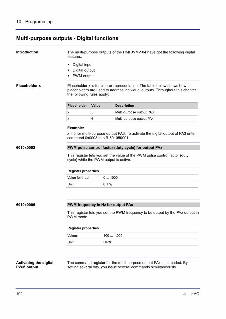
192 Jetter AG
10 Programming
Multi-purpose outputs - Digital functions
The multi-purpose outputs of the HMI JVM-104 have got the following digital features:
Digital input Digital output PWM output
Placeholder x is for clearer representation. The table below shows how placeholders are used to address individual outputs. Throughout this chapter the following rules apply:
Placeholder Value Description
x 5 Multi-purpose output PA3
x 6 Multi-purpose output PA4
Example: x = 5 for multi-purpose output PA3. To activate the digital output of PA3 enter command 0x0008 into R 601050001.
PWM pulse control factor (duty cycle) for output PAx
This register lets you set the value of the PWM pulse control factor (duty cycle) while the PWM output is active.
Register properties
Value for input 0 ... 1000
Unit 0.1 %
PWM frequency in Hz for output PAx
This register lets you set the PWM frequency to be output by the PAx output in PWM mode.
Register properties
Values 100 ... 1,000
Unit Hertz
The command register for the multi-purpose output PAx is bit-coded. By setting several bits, you issue several commands simultaneously.
Introduction
Placeholder x
6010x0002
6010x0006
Activating the digital PWM output
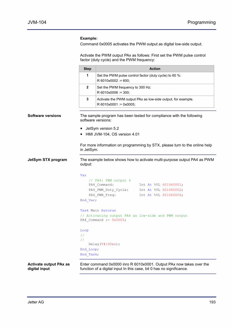
Jetter AG 193
JVM-104 Programming
Example: Command 0x0005 activates the PWM output as digital low-side output. Activate the PWM output PAx as follows: First set the PWM pulse control factor (duty cycle) and the PWM frequency:
Step Action
1 Set the PWM pulse control factor (duty cycle) to 60 %: R 6010x0002 := 600;
2 Set the PWM frequency to 300 Hz: R 6010x0006 := 300;
3 Activate the PWM output PAx as low-side output, for example. R 6010x0001 := 0x0005;
The sample program has been tested for compliance with the following software versions:
JetSym version 5.2 HMI JVM-104, OS version 4.01 For more information on programming by STX, please turn to the online help in JetSym.
The example below shows how to activate multi-purpose output PA4 as PWM output: Var
// PA4: PWM output 4 PA4_Command: Int At %VL 601060001;
PA4_PWM_Duty_Cycle: Int At %VL 601060002;
PA4_PWM_Freq: Int At %VL 601060006;
End_Var;
Task Main Autorun
// Activating output PA4 as low-side and PWM output PA4_Command := 0x0005;
Loop
// // Delay(T#100ms);
End_Loop;
End_Task;
Enter command 0x0000 inro R 6010x0001. Output PAx now takes over the function of a digital input In this case, bit 0 has no significance.
Software versions
JetSym STX program
Activate output PAx as digital input

194 Jetter AG
10 Programming
Multi-purpose outputs PA3 and PA4 functioning as H-bridges
The HMI JVM-104 lets you control multi-purpose outputs PA3 and PA4 as H-bridges.
To control an output as H-bridge, the program must include the following steps: Clockwise rotation:
Step Action
1 Activate the low-side output of PA3. R 601050001 := 0x0005;
2 Set PA3 to a PWM pulse control factor (duty cycle) of 100 %. R 601050002 := 1000;
3 Activate the high-side output of PA4: R 601060001 := 0x0009;
4 Set PA4 to the desired PWM pulse control factor (duty cycle), e.g. 50 %. R 601060002 := 500;
The H-bridge in clockwise rotation is configured with a 50 % pulse control factor (duty cycle).
Anti-clockwise rotation:
Step Action
1 Activate the low-side output of PA4. R 601060001 := 0x0005;
2 Set PA4 to the PWM pulse control factor (duty cycle) of 100 %. R 601060002 := 1000;
3 Activate the high-side output of PA3. R 601050001 := 0x0009;
4 Set PA3 to the desired PWM pulse control factor (duty cycle), e.g. 40 %. R 601050002 := 400;
The H-bridge in anti-clockwise rotation is configured with a 40 % pulse control factor (duty cycle).
The sample program has been tested for compliance with the following software versions:
JetSym version 5.2 HMI JVM-104, OS version 4.01 For more information on programming by STX, please turn to the online help in JetSym.
Introduction
Programming
Software versions
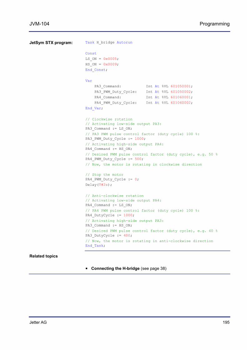
Jetter AG 195
JVM-104 Programming
Task H_bridge Autorun
Const
LS_ON = 0x0005;
HS_ON = 0x0009;
End_Const;
Var
PA3_Command: Int At %VL 601050001;
PA3_PWM_Duty_Cycle: Int At %VL 601050002;
PA4_Command: Int At %VL 601060001;
PA4_PWM_Duty_Cycle: Int At %VL 601060002;
End_Var;
// Clockwise rotation // Activating low-side output PA3: PA3_Command := LS_ON;
// PA3 PWM pulse control factor (duty cycle) 100 %: PA3_PWM_Duty_Cycle := 1000;
// Activating high-side output PA4: PA4_Command := HS_ON;
// Desired PWM pulse control factor (duty cycle), e.g. 50 % PA4_PWM_Duty_Cycle := 500;
// Now, the motor is rotating in clockwise direction
// Stop the motor PA4_PWM_Duty_Cycle := 0;
Delay(T#2s);
// Anti-clockwise rotation // Activating low-side output PA4: PA4_Command := LS_ON;
// PA4 PWM pulse control factor (duty cycle) 100 %: PA4_DutyCycle := 1000;
// Activating high-side output PA3: PA3_Command := HS_ON;
// Desired PWM pulse control factor (duty cycle), e.g. 40 % PA3_DutyCycle := 400;
// Now, the motor is rotating in anti-clockwise direction End_Task;
Connecting the H-bridge (see page 38)
JetSym STX program:
Related topics
196 Jetter AG
10 Programming
10.4 Runtime registers
The JVM-104 provides several registers which are incremented by the operating system at regular intervals.
These registers can be used to easily carry out time measurements in the application program.
Topic Page Description of the runtime registers ............................................................ 197 Sample program - Runtime registers .......................................................... 199
Introduction
Application
Contents
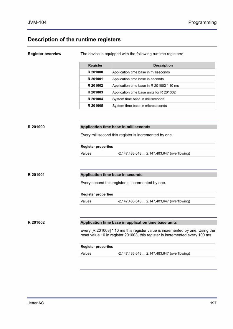
Jetter AG 197
JVM-104 Programming
Description of the runtime registers
The device is equipped with the following runtime registers:
Register Description
R 201000 Application time base in milliseconds
R 201001 Application time base in seconds
R 201002 Application time base in R 201003 * 10 ms
R 201003 Application time base units for R 201002
R 201004 System time base in milliseconds
R 201005 System time base in microseconds
Application time base in milliseconds
Every millisecond this register is incremented by one.
Register properties
Values -2,147,483,648 ... 2,147,483,647 (overflowing)
Application time base in seconds
Every second this register is incremented by one.
Register properties
Values -2,147,483,648 ... 2,147,483,647 (overflowing)
Application time base in application time base units
Every [R 201003] * 10 ms this register value is incremented by one. Using the reset value 10 in register 201003, this register is incremented every 100 ms.
Register properties
Values -2,147,483,648 ... 2,147,483,647 (overflowing)
Register overview
R 201000
R 201001
R 201002

198 Jetter AG
10 Programming
Application time base units for R 201002
This register contains the multiplier for runtime register R 201002.
Register properties
Values 1 ... 2,147,483,647 (* 10 ms)
Value after reset 10 (--> 100 ms)
Enabling conditions After at least 10 ms
System time base in milliseconds
Every millisecond this register value is incremented by one.
Register properties
Values -2,147,483,648 ... 2,147,483,647 (overflowing)
Type of access Read
System time base in microseconds
Every microsecond this register value is incremented by one.
Register properties
Values -2,147,483,648 ... 2,147,483,647 (overflowing)
Type of access Read
R 201003
R 201004
R 201005

Jetter AG 199
JVM-104 Programming
Sample program - Runtime registers
Measure how much time it takes to store variable values to a file.
Before storing the values, set register 201000 to 0. Once the values have been stored, you can see from this register how much time it took to store the values [in milliseconds].
The sample program has been tested for compliance with the following software versions:
JetSym version 5.2 HMI JVM-104, OS version 4.01 For more information on programming by STX, please turn to the online help in JetSym.
Var
DataArray: Array[2000] Of Int;
File1: File;
WriteTime: Int;
WriteIt: Bool;
MilliSec: Int At %VL 201000;
End_Var;
Task WriteToFile Autorun
Loop
// Resetting the start flag WriteIt := False;
// Waiting for user to set start flag When WriteIt Continue;
// Opening the file in write mode // If there is no file available, a new file // is created If FileOpen(File1, 'Test.dat', fWrite) Then
// Setting the application time base register to zero MilliSec := 0;
// Writing the data array into the file FileWrite(File1, DataArray, SizeOf(DataArray));
// Registering the run time WriteTime := MilliSec;
FileClose(File1);
// Displaying the run time Trace(StrFormat('Time : %d [ms]$n', WriteTime));
Task
Solution
Software versions
JetSym STX program

200 Jetter AG
10 Programming
Else
// Displaying the error message Trace('Unable to open file!$n');
End_If;
End_Loop;
End_Task;

Jetter AG 201
JVM-104 Programming
10.5 Monitoring interface activities
Several Ethernet servers have been integrated into the HMI to make variables used within the application program accessible from outside. These servers support several protocols on different interfaces. The servers do not require any programming in the application program, but process requests from external clients on their own. This chapter explains one possibility for detecting from within the application program whether communication with the servers takes place through these interfaces.
The following interface activities can be monitored:
JetIP server via Ethernet interface STX debug server via Ethernet interface
The monitoring function for interface activities is used, amongst others, for the following scenarios:
Plants requiring process visualization to ensure safe operation. They can be transferred into a save state if communications fails.
When the service technician connects an HMI, the application program automatically displays additional status information.
Topic Page Operating principle ..................................................................................... 202 Programming .............................................................................................. 204
Introduction
Monitored interface activities
Purpose
Contents

202 Jetter AG
10 Programming
Operating principle
The application program monitors the activity of a client communicating with a server of the device JVM-104 by means of two special flags and one special register per interface.
The illustration below shows the interdependence between interface activity and the two special flags, as well as the special register:
Telegrams
OS Flag
User Flag
Timeout
Application program:WHEN OS_FLAG ContinueUser_FLAG := TRUE;
1
2
3
4
Number Element Description
1 Telegrams The client places requests to the server.
2 OS flag OS flag set by the device JVM-104 after receiving a request
3 User flag You must set the user flag in the application program once the device has set the OS flag.This indicates that the connection has temporarily been disrupted even if the device resets the OS flag very quickly.
4 Timeout Time of inactivity after which the OS resets both special flags. This time can be set in a special register.
Interface activities are monitored as follows:
Step Description
1 Enter the desired value into the timeout register of the application program. This way, the monitoring mode is activated as well.
2 When the controller receives the next telegram, the device JVM-104 sets the corresponding OS flag.
3 If the OS flag has been set, the application program also sets the respective user flag.
4 Each new telegram causes the timeout to restart.
5 If telegrams cease to arrive, both special flags are reset by the controller upon expiry of the timeout interval.
Introduction
Overview
Description

Jetter AG 203
JVM-104 Programming
Step Description
6 The application program detects that the device has reset the special flags and therefore takes appropriate action.
7 When further telegrams start arriving, the device sets the corresponding OS flag. The user flag, however, remains reset.
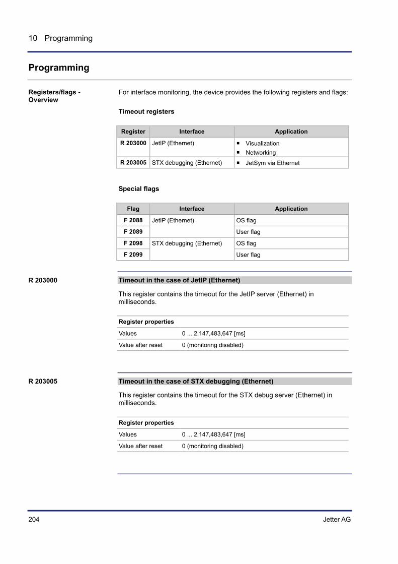
204 Jetter AG
10 Programming
Programming
For interface monitoring, the device provides the following registers and flags: Timeout registers
Register Interface Application
R 203000 JetIP (Ethernet) Visualization Networking
R 203005 STX debugging (Ethernet) JetSym via Ethernet
Special flags
Flag Interface Application
F 2088 JetIP (Ethernet) OS flag
F 2089 User flag
F 2098 STX debugging (Ethernet) OS flag
F 2099 User flag
Timeout in the case of JetIP (Ethernet)
This register contains the timeout for the JetIP server (Ethernet) in milliseconds.
Register properties
Values 0 ... 2,147,483,647 [ms]
Value after reset 0 (monitoring disabled)
Timeout in the case of STX debugging (Ethernet)
This register contains the timeout for the STX debug server (Ethernet) in milliseconds.
Register properties
Values 0 ... 2,147,483,647 [ms]
Value after reset 0 (monitoring disabled)
Registers/flags - Overview
R 203000
R 203005
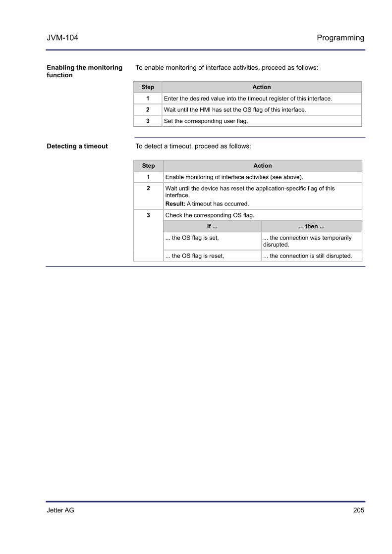
Jetter AG 205
JVM-104 Programming
To enable monitoring of interface activities, proceed as follows:
Step Action
1 Enter the desired value into the timeout register of this interface.
2 Wait until the HMI has set the OS flag of this interface.
3 Set the corresponding user flag.
To detect a timeout, proceed as follows:
Step Action
1 Enable monitoring of interface activities (see above).
2 Wait until the device has reset the application-specific flag of this interface. Result: A timeout has occurred.
3 Check the corresponding OS flag.
If ... ... then ...
... the OS flag is set, ... the connection was temporarily disrupted.
... the OS flag is reset, ... the connection is still disrupted.
Enabling the monitoring function
Detecting a timeout
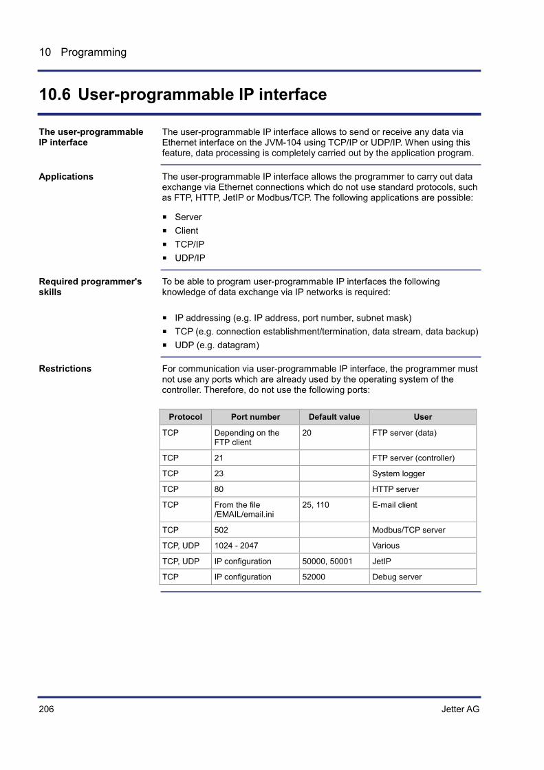
206 Jetter AG
10 Programming
10.6 User-programmable IP interface
The user-programmable IP interface allows to send or receive any data via Ethernet interface on the JVM-104 using TCP/IP or UDP/IP. When using this feature, data processing is completely carried out by the application program.
The user-programmable IP interface allows the programmer to carry out data exchange via Ethernet connections which do not use standard protocols, such as FTP, HTTP, JetIP or Modbus/TCP. The following applications are possible:
Server Client TCP/IP UDP/IP
To be able to program user-programmable IP interfaces the following knowledge of data exchange via IP networks is required:
IP addressing (e.g. IP address, port number, subnet mask) TCP (e.g. connection establishment/termination, data stream, data backup) UDP (e.g. datagram)
For communication via user-programmable IP interface, the programmer must not use any ports which are already used by the operating system of the controller. Therefore, do not use the following ports:
Protocol Port number Default value User
TCP Depending on the FTP client
20 FTP server (data)
TCP 21 FTP server (controller)
TCP 23 System logger
TCP 80 HTTP server
TCP From the file /EMAIL/email.ini
25, 110 E-mail client
TCP 502 Modbus/TCP server
TCP, UDP 1024 - 2047 Various
TCP, UDP IP configuration 50000, 50001 JetIP
TCP IP configuration 52000 Debug server
The user-programmable IP interface
Applications
Required programmer's skills
Restrictions

Jetter AG 207
JVM-104 Programming
Topic Page Programming .............................................................................................. 208 Registers ..................................................................................................... 220 Sample programs ....................................................................................... 225
Contents

208 Jetter AG
10 Programming
10.6.1 Programming
The user-programmable IP interface is used to carry out data exchange between application program and network client via TCP/IP or UDP/IP connections. For this purpose, function calls are used. These function calls are included in the programming language of the JVM-104. To program this feature proceed as follows:
Step Action
1 Initializing the user-programmable IP interface
2 Open connections
3 Transfer data
4 Terminate the connections
Technical data of the user-programmable IP interface:
Feature Description
Number of connections 20
Maximum data size 4,000 byte
While the controller JVM-104 is processing one of the functions of the user-programmable IP interface, tasks having called the functions should not be stopped through TaskBreak or restarted through TaskRestart. Failure to do so could result in the following errors:
Connections do not open Data loss during sending or receiving Connections remain open unintentionally Connections are closed unintentionally
Topic Page Initializing the user-programmable IP interface .......................................... 209 Establishing a connection ........................................................................... 210 Sending data ............................................................................................... 214 Receiving data ............................................................................................ 216 Terminating a connection ............................................................................ 219
Introduction
Technical data
Restrictions
Contents
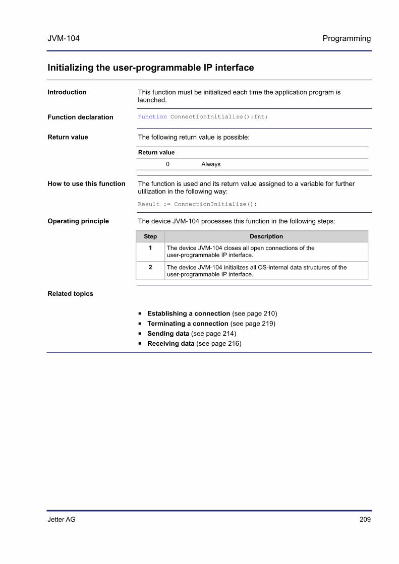
Jetter AG 209
JVM-104 Programming
Initializing the user-programmable IP interface
This function must be initialized each time the application program is launched.
Function ConnectionInitialize():Int;
The following return value is possible:
Return value
0 Always
The function is used and its return value assigned to a variable for further utilization in the following way:
Result := ConnectionInitialize();
The device JVM-104 processes this function in the following steps:
Step Description
1 The device JVM-104 closes all open connections of the user-programmable IP interface.
2 The device JVM-104 initializes all OS-internal data structures of the user-programmable IP interface.
Establishing a connection (see page 210) Terminating a connection (see page 219) Sending data (see page 214) Receiving data (see page 216)
Introduction
Function declaration
Return value
How to use this function
Operating principle
Related topics
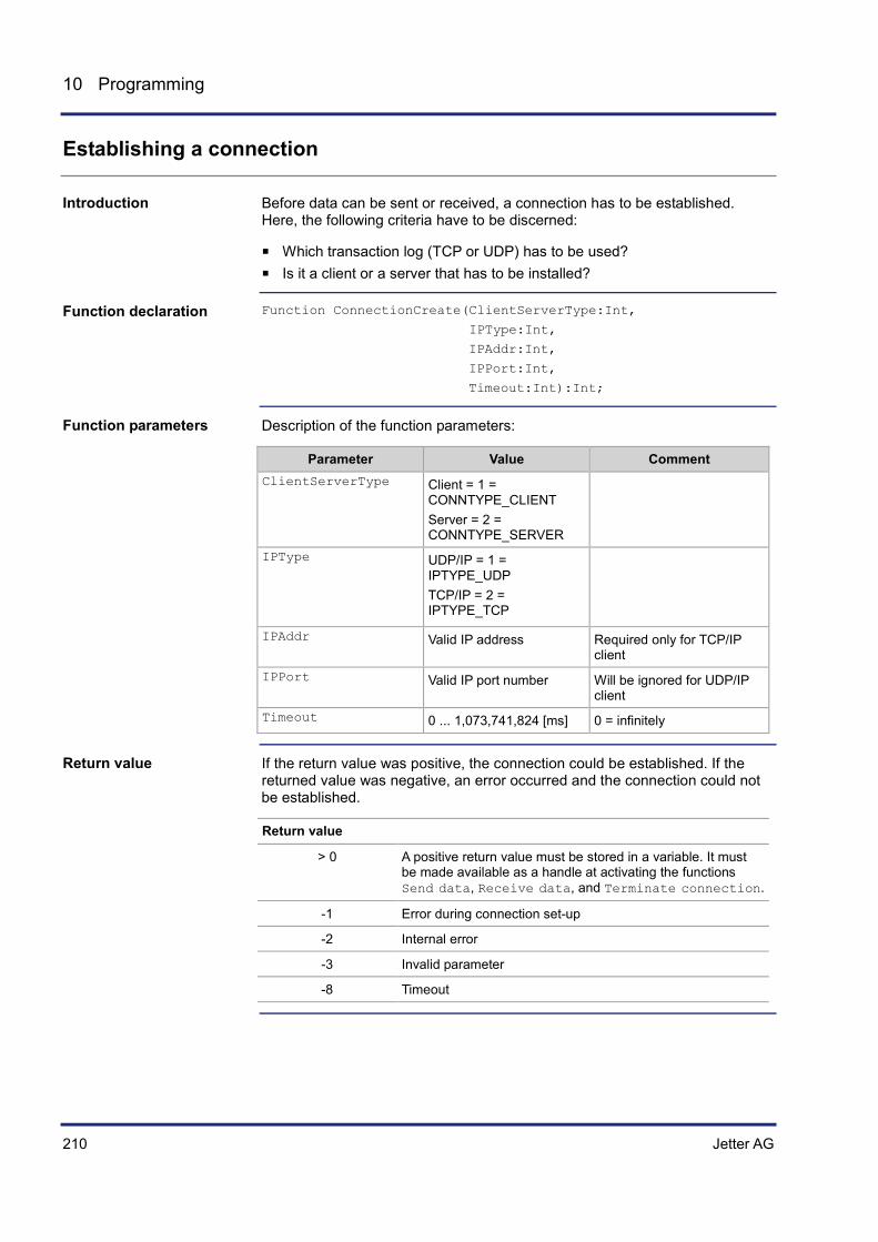
210 Jetter AG
10 Programming
Establishing a connection
Before data can be sent or received, a connection has to be established. Here, the following criteria have to be discerned:
Which transaction log (TCP or UDP) has to be used? Is it a client or a server that has to be installed?
Function ConnectionCreate(ClientServerType:Int,
IPType:Int,
IPAddr:Int,
IPPort:Int,
Timeout:Int):Int;
Description of the function parameters:
Parameter Value Comment ClientServerType Client = 1 =
CONNTYPE_CLIENT Server = 2 = CONNTYPE_SERVER
IPType UDP/IP = 1 = IPTYPE_UDP TCP/IP = 2 = IPTYPE_TCP
IPAddr Valid IP address Required only for TCP/IP client
IPPort Valid IP port number Will be ignored for UDP/IP client
Timeout 0 ... 1,073,741,824 [ms] 0 = infinitely
If the return value was positive, the connection could be established. If the returned value was negative, an error occurred and the connection could not be established.
Return value
> 0 A positive return value must be stored in a variable. It must be made available as a handle at activating the functions Send data, Receive data, and Terminate connection.
-1 Error during connection set-up
-2 Internal error
-3 Invalid parameter
-8 Timeout
Introduction
Function declaration
Function parameters
Return value

Jetter AG 211
JVM-104 Programming
If a client is to establish a TCP/IP connection to a server, you can invoke the function and assign the return value of a variable for further evaluation as follows: Result := ConnectionCreate(CONNTYPE_CLIENT,
IPTYPE_TCP,
IP#192.168.75.123,
46000,
T#10s);
The task stops at the program line until the connection is established or the specified timeout has elapsed. This function is processed in the following steps:
Step Description
1 The device JVM-104 tries to establish a TCP/IP connection via port 46000 to the network client with IP address 192.168.75.123.
2 If ... ... then ...
the network client has accepted the connection,
the function is terminated and a positive value is returned as handle for further access to the connection.
the connection could not be established and the timeout of 10 seconds has not elapsed yet,
step 1 is carried out.
an error has occurred or the timeout has elapsed,
the function is terminated and a negative value is returned.
If a server is to establish a TCP/IP connection to a client, you can invoke the function and assign the return value of a variable for further evaluation as follows:
Result := ConnectionCreate(CONNTYPE_SERVER,
IPTYPE_TCP,
0,
46000,
T#100s);
Using this function with a TCP/IP client
Functioning principle with a TCP/IP client
Using this function with a TCP/IP server
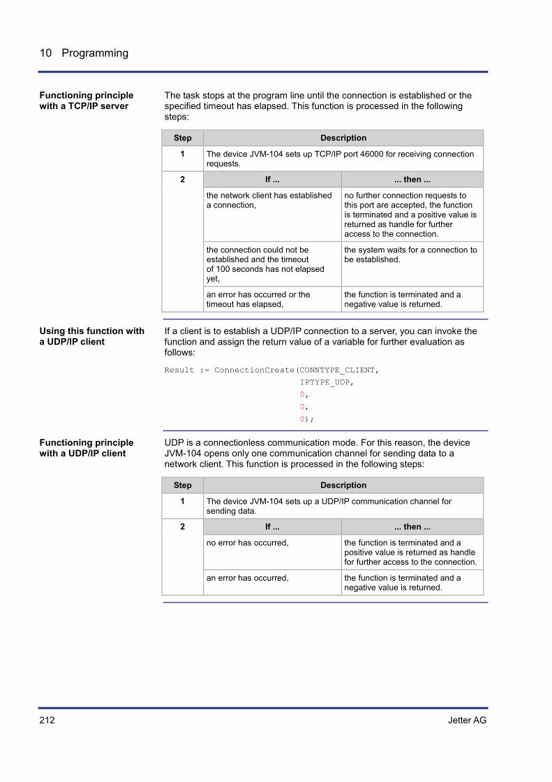
212 Jetter AG
10 Programming
The task stops at the program line until the connection is established or the specified timeout has elapsed. This function is processed in the following steps:
Step Description
1 The device JVM-104 sets up TCP/IP port 46000 for receiving connection requests.
2 If ... ... then ...
the network client has established a connection,
no further connection requests to this port are accepted, the function is terminated and a positive value is returned as handle for further access to the connection.
the connection could not be established and the timeout of 100 seconds has not elapsed yet,
the system waits for a connection to be established.
an error has occurred or the timeout has elapsed,
the function is terminated and a negative value is returned.
If a client is to establish a UDP/IP connection to a server, you can invoke the function and assign the return value of a variable for further evaluation as follows:
Result := ConnectionCreate(CONNTYPE_CLIENT,
IPTYPE_UDP,
0,
0,
0);
UDP is a connectionless communication mode. For this reason, the device JVM-104 opens only one communication channel for sending data to a network client. This function is processed in the following steps:
Step Description
1 The device JVM-104 sets up a UDP/IP communication channel for sending data.
2 If ... ... then ...
no error has occurred, the function is terminated and a positive value is returned as handle for further access to the connection.
an error has occurred, the function is terminated and a negative value is returned.
Functioning principle with a TCP/IP server
Using this function with a UDP/IP client
Functioning principle with a UDP/IP client
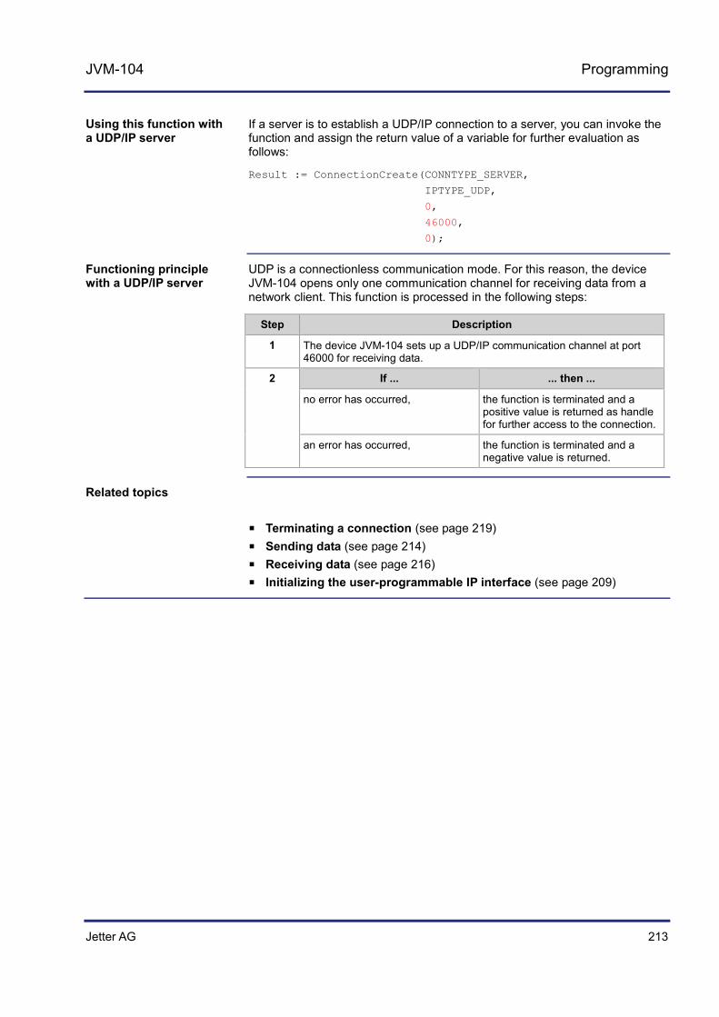
Jetter AG 213
JVM-104 Programming
If a server is to establish a UDP/IP connection to a server, you can invoke the function and assign the return value of a variable for further evaluation as follows:
Result := ConnectionCreate(CONNTYPE_SERVER,
IPTYPE_UDP,
0,
46000,
0);
UDP is a connectionless communication mode. For this reason, the device JVM-104 opens only one communication channel for receiving data from a network client. This function is processed in the following steps:
Step Description
1 The device JVM-104 sets up a UDP/IP communication channel at port 46000 for receiving data.
2 If ... ... then ...
no error has occurred, the function is terminated and a positive value is returned as handle for further access to the connection.
an error has occurred, the function is terminated and a negative value is returned.
Terminating a connection (see page 219) Sending data (see page 214) Receiving data (see page 216) Initializing the user-programmable IP interface (see page 209)
Using this function with a UDP/IP server
Functioning principle with a UDP/IP server
Related topics

214 Jetter AG
10 Programming
Sending data
Data can be sent via a previously established TCP/IP connection or via a UDP/IP connection of a client. Via UDP/IP connection of a server data cannot be sent, but only received.
Function ConnectionSendData(IPConnection:Int,
IPAddr:Int,
IPPort:Int,
Const Ref SendData,
DataLen:Int):Int;
Description of the function parameters:
Parameter Value Comment IPConnection Handle Return value of the function
ConnectionCreate()
IPAddr Valid IP address Required only for UDP/IP client
IPPort Valid IP port number Required only for UDP/IP client
SendData Address of the data block to be sent
1 ... 4,000 Data block length in bytes
The following return values are possible:
Return value
0 Data have been sent successfully.
-1 Error when sending, e.g. connection interrupted.
-3 Invalid handle, e.g. sending via a UDP/IP server.
If data are to be sent via a TCP/IP connection, you can invoke the function and assign the return value of a variable for further evaluation as follows:
Result := ConnectionSendData(hConnection,
0,
0,
SendBuffer,
SendLen);
Introduction
Function declaration
Function parameters
Return value
Using this function with a TCP/IP connection

Jetter AG 215
JVM-104 Programming
When using TCP/IP, data are sent via a previously opened connection. Therefore, specification of the IP address and IP port number is not required anymore and can be ignored in the function. In the following cases, the task is not processed further after issuing the function call:
The data have been sent and their reception confirmed. An error has occurred.
If, with a client, data are to be sent via a UDP/IP connection, you can invoke the function and assign the return value of a variable for further evaluation as follows:
Result := ConnectionData(hConnection,
IP#192.168.75.123,
46000,
SendBuffer,
SendLen);
With UDP/IP there is no connection between two given network clients. Therefore, with each function call data can be sent to another client or another port. The task will pause at the function call until the data are sent. You will not get any acknowledgment of the remote network client having received the data.
Initializing the user-programmable IP interface (see page 209) Establishing a connection (see page 210) Terminating a connection (see page 219) Receiving data (see page 216)
Functioning principle with a TCP/IP connection
Using this function with a UDP/IP client
Functioning principle with a UDP/IP client
Related topics

216 Jetter AG
10 Programming
Receiving data
Data can be sent via a previously established TCP/IP connection or via a UDP/IP connection of a server. Via UDP/IP connection of a client data cannot be received, but only sent.
Function ConnectionReceiveData(IPConnection:Int,
Ref IPAddr:Int,
Ref IPPort:Int,
Ref ReceiveData,
DataLen:Int,
Timeout:Int):Int;
Description of the function parameters:
Parameter Value Comment IPConnection Handle Return value of the function
ConnectionCreate()
IPAddr Address of a variable for saving the IP address of the sender
Required only for UDP/IP server
IPPort Address of a variable for saving the IP port number of the sender
Required only for UDP/IP server
ReceiveData Address of the data block to be received
DataLen 1 ... 4,000 Maximum data block length in bytes
Timeout 0 ... 1,073,741,824 [ms] 0 = infinitely
The following return values are possible:
Return value
> 0 Number of received data bytes
-1 Error when receiving data, e.g. connection interrupted.
-3 Invalid handle, e.g. receiving data via a UDP/IP client.
-8 Timeout
Introduction
Function declaration
Function parameters
Return value

Jetter AG 217
JVM-104 Programming
If data are to be received via a TCP/IP connection, you can invoke the function and assign the return value of a variable for further evaluation as follows:
Result := ConnectionReceiveData(hConnection,
Dummy,
Dummy,
ReceiveBuffer,
sizeof(ReceiveBuffer),
T#10s);
When using TCP/IP, data are sent via a previously opened connection. Therefore, specification of the IP address and IP port number is not required any more and can be ignored in the function. In the following cases, the task is not processed further after issuing the function call:
The data have been received An error has occurred In case of a TCP/IP connection, data are transmitted as data stream. The device JVM-104 processes this function in the following steps:
Step Description
1 The device JVM-104 waits until data have been received, but no longer than the specified timeout.
2 If ... ... then ...
the timeout has elapsed or the connection has been terminated,
the function is exited and an error message is issued.
data have been received, they are copied to the receiving buffer given along with the data (but not exceeding the amount given along with the data). Then, the function continues with stage 3.
3 If ... ... then ...
more data have been received than could have been copied into the receiving buffer,
these are buffered by the JVM-104 to be fetched by further function calls.
4 The function is exited and the number of data, which have been copied into the receiving buffer, is returned.
If, with a server, data are to be received via a UDP/IP connection, you can invoke the function and assign the return value of a variable for further evaluation as follows:
Result := ConnectionReceiveData(hConnection,
IPAddr,
IPPort,
ReceiveBuffer,
sizeof(ReceiveBuffer),
T#10s);
Using this function with a TCP/IP connection
Functioning principle with a TCP/IP connection
Using this function with a UDP/IP server
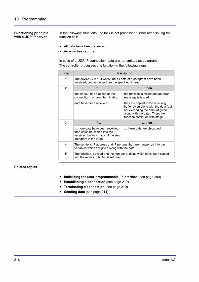
218 Jetter AG
10 Programming
In the following situations, the task is not processed further after issuing the function call:
All data have been received. An error has occurred. In case of a UDP/IP connection, data are transmitted as datagram. The controller processes this function in the following steps:
Step Description
1 The device JVM-104 waits until all data of a datagram have been received, but no longer than the specified timeout.
2 If ... ... then ...
the timeout has elapsed or the connection has been terminated,
the function is exited and an error message is issued.
data have been received, they are copied to the receiving buffer given along with the data (but not exceeding the amount given along with the data). Then, the function continues with stage 3.
3 If ... ... then ...
... more data have been received than could be copied into the receiving buffer - that is, if the sent datagram is too large,
... these data are discarded.
4 The sender's IP address and IP port number are transferred into the variables which are given along with the data.
5 The function is exited and the number of data, which have been copied into the receiving buffer, is returned.
Initializing the user-programmable IP interface (see page 209) Establishing a connection (see page 210) Terminating a connection (see page 219) Sending data (see page 214)
Functioning principle with a UDP/IP server
Related topics

Jetter AG 219
JVM-104 Programming
Terminating a connection
Clear all connections which are no longer required as the number of concurrently opened connections is limited.
Function ConnectionDelete(IPConnection:Int):Int;
Description of the function parameters:
Parameter Value Comment IPConnection Handle Return value of the function
ConnectionCreate()
The following return values are possible:
Return value
0 Connection terminated and deleted
-1 Invalid handle
This way, you can invoke the function and assign its return value to a variable for further utilization:
Result := ConnectionDelete(hConnection);
Establishing a connection (see page 210) Sending data (see page 214) Receiving data (see page 216) Initializing the user-programmable IP interface (see page 209)
Introduction
Function declaration
Function parameters
Return value
How to use this function
Related topics

220 Jetter AG
10 Programming
10.6.2 Registers
This chapter describes the registers of the JVM-104 which contain the current connection list of the user-programmable IP interface. These registers can be used for debugging or diagnostic purposes. However, they can't be used for other functions such as establishing or terminating a connection.
Topic Page Register numbers ........................................................................................ 221 Register description .................................................................................... 222
Introduction
Contents

Jetter AG 221
JVM-104 Programming
Register numbers
Data of one connection each are displayed within the registers of a coherent register block. The basic register number of this block is dependent on the controller.
Controller Basic register number Register numbers
JC-340, JC-350, JC-360, JC-360MC
350000 350000 ... 350007
JC-940MC 350000 350000 ... 350007
JVM-407, JVM-407B 350000 350000 ... 350007
JVM-104 350000 350000 ... 350007
In this chapter only the last figure of a register number is specified, for example MR 1. To determine the complete module register number, add to this figure the basic register number of the corresponding device, for example 350000.
Register Description
MR 0 Selecting a connection
MR 1 Type of connection
MR 2 Transport protocol
MR 3 IP address
MR 4 IP port number
MR 5 State
MR 6 Number of sent bytes
MR 7 Number of received bytes
Introduction
Register numbers
Determining the register number
Register overview

222 Jetter AG
10 Programming
Register description
The operating system manages the established connections in a list. Module register MR 0 Selection of a connection is used to copy connection details into other registers of a register block.
Selecting a connection
Connections are selected by writing values to this register. Read access to this register is used to display whether the following registers contain connection details.
Module register properties
Reading values 0 Connection exists
-1 Connection does not exist
Module register properties
Writing values 0 Address the first connection in the list
> 0 Address the next connection in the list
< 0 Address the previous connection in the list
Type of connection
The value in this register shows whether the connection is a client or a server connection.
Module register properties
Values 1 Client
2 Server
Transport protocol
The value in this register shows whether TCP or UDP is used as transport protocol.
Module register properties
Values 1 UDP
2 TCP
Introduction
MR 0
MR 1
MR 2

Jetter AG 223
JVM-104 Programming
IP address
The value in this register shows the configured IP address.
Module register properties
Values 0,0,0,0 ... 255,255,255,255
IP port number
The value in this register shows the configured IP port number.
Module register properties
Values 0 ... 65,535
State
The value in this register shows status the connection is currently in.
Module register properties
Values 0 Connection terminated
1 Connection is being established
2 Connection is established
3 TCP/IP server: Waiting for connection request from client
4 Internal usage
Number of sent bytes
The value in this register shows the number of data bytes sent via the given connection. Since this is a signed 32-bit register and the sent bytes are added each time, the number range may be exceeded from the positive maximum value to the negative maximum value.
Module register properties
Values -2,147,483,648 ... 2,147,483,647
MR 3
MR 4
MR 5
MR 6

224 Jetter AG
10 Programming
Number of received bytes
The value in this register shows the number of data bytes received via the given connection. Since this is a signed 32-bit register and the received bytes are added each time, the number range may be exceeded from the positive maximum value to the negative maximum value.
Module register properties
Values -2,147,483,648 ... 2,147,483,647
MR 7

Jetter AG 225
JVM-104 Programming
10.6.3 Sample programs
This chapter contains sample programs for implementing a server and a corresponding client which will use TCP/IP for communication. Both sample programs can be applied to the HMI JVM-104. Due to the platform-independent implementation of the user-programmable IP interface these sample programs can be used for other configurations without modification.
The use case is a Jetter AG controller or HMI communicating with a device from a third-party manufacturer. The user-programmable IP interface lets you make protocol adjustments in the application program of the Jetter AG device.
Topic Page Server ......................................................................................................... 226 Client ........................................................................................................... 230
Introduction
Use case
Contents
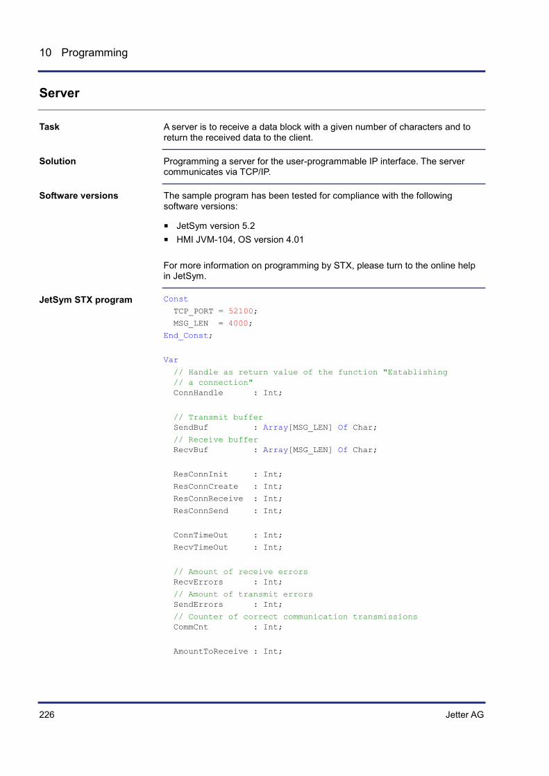
226 Jetter AG
10 Programming
Server
A server is to receive a data block with a given number of characters and to return the received data to the client.
Programming a server for the user-programmable IP interface. The server communicates via TCP/IP.
The sample program has been tested for compliance with the following software versions:
JetSym version 5.2 HMI JVM-104, OS version 4.01 For more information on programming by STX, please turn to the online help in JetSym.
Const
TCP_PORT = 52100;
MSG_LEN = 4000;
End_Const;
Var
// Handle as return value of the function "Establishing // a connection" ConnHandle : Int;
// Transmit buffer SendBuf : Array[MSG_LEN] Of Char;
// Receive buffer RecvBuf : Array[MSG_LEN] Of Char;
ResConnInit : Int;
ResConnCreate : Int;
ResConnReceive : Int;
ResConnSend : Int;
ConnTimeOut : Int;
RecvTimeOut : Int;
// Amount of receive errors RecvErrors : Int;
// Amount of transmit errors SendErrors : Int;
// Counter of correct communication transmissions CommCnt : Int;
AmountToReceive : Int;
Task
Solution
Software versions
JetSym STX program

Jetter AG 227
JVM-104 Programming
// Dummy NotUsed : Int;
End_Var;
Task TCPserver Autorun
Var
RecvTimer : Timer;
ReceiveCnt : Int;
End_Var;
// Timeout for connection ConnTimeOut := T#5s;
// Timeout when receiving a data packet RecvTimeOut := T#5s;
// Amount of data to be received AmountToReceive := MSG_LEN;
// Terminate all connections, initialize the data structures ResConnInit := ConnectionInitialize();
If ResConnInit >= 0 Then
Trace('Server running.$n');
While (True) Do
// Connection attempt ResConnCreate := ConnectionCreate
( CONNTYPE_SERVER,
IPTYPE_TCP,
0,
TCP_PORT,
ConnTimeOut );
If ResConnCreate > 0 Then
Trace('Connection established.');
// Save the return value (handle) ConnHandle := ResConnCreate;
// Repeat, while the connection exists Loop
// Set up a timeout for completely transmitting the data packet TimerStart(RecvTimer, RecvTimeOut * 5);
// Initialize the counter for the received data ReceiveCnt := 0;
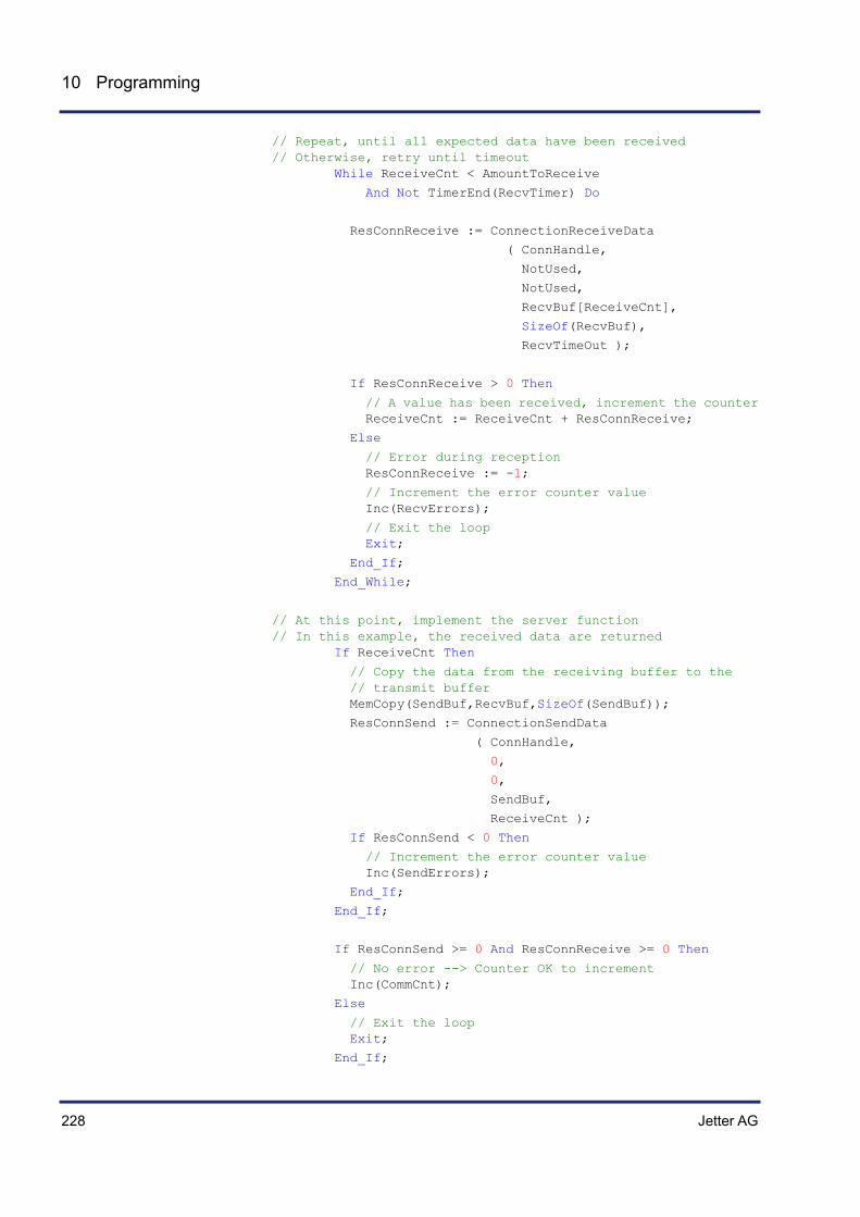
228 Jetter AG
10 Programming
// Repeat, until all expected data have been received // Otherwise, retry until timeout While ReceiveCnt < AmountToReceive
And Not TimerEnd(RecvTimer) Do
ResConnReceive := ConnectionReceiveData
( ConnHandle,
NotUsed,
NotUsed,
RecvBuf[ReceiveCnt],
SizeOf(RecvBuf),
RecvTimeOut );
If ResConnReceive > 0 Then
// A value has been received, increment the counter ReceiveCnt := ReceiveCnt + ResConnReceive;
Else
// Error during reception ResConnReceive := -1;
// Increment the error counter value Inc(RecvErrors);
// Exit the loop Exit;
End_If;
End_While;
// At this point, implement the server function // In this example, the received data are returned If ReceiveCnt Then
// Copy the data from the receiving buffer to the // transmit buffer MemCopy(SendBuf,RecvBuf,SizeOf(SendBuf));
ResConnSend := ConnectionSendData
( ConnHandle,
0,
0,
SendBuf,
ReceiveCnt );
If ResConnSend < 0 Then
// Increment the error counter value Inc(SendErrors);
End_If;
End_If;
If ResConnSend >= 0 And ResConnReceive >= 0 Then
// No error --> Counter OK to increment Inc(CommCnt);
Else
// Exit the loop Exit;
End_If;

Jetter AG 229
JVM-104 Programming
End_Loop;
If ConnHandle > 0 Then
// Terminate the connection ConnectionDelete(ConnHandle);
// Handle is no longer valid ConnHandle := 0;
Trace('Connection closed.$n');
End_If;
End_If;
// Wait shortly for another connection to be tried Delay(T#3s);
End_While;
Else
Trace('ConnectionInitialize() failed, server stopped !$n');
End_If;
End_Task;
Client (see page 230)
Related topics

230 Jetter AG
10 Programming
Client
A client is to send a data block with a given number of characters and to return the data received from the server.
Programming a client for the user-programmable IP interface. The client communicates via TCP/IP.
The sample program has been tested for compliance with the following software versions:
JetSym version 5.2 HMI JVM-104, OS version 4.01 For more information on programming by STX, please turn to the online help in JetSym.
Const
TCP_ADDR = IP#192.168.10.210;
TCP_PORT = 52100;
MSG_LEN = 4000;
End_Const;
Var
// Handle as return value of the function "Establishing // a connection" ConnHandle : Int;
// Transmit buffer SendBuf : Array[MSG_LEN] Of Char;
// Receive buffer RecvBuf : Array[MSG_LEN] Of Char;
ResConnInit : Int;
ResConnCreate : Int;
ResConnReceive : Int;
ResConnSend : Int;
ConnTimeOut : Int;
RecvTimeOut : Int;
// Amount of receive errors RecvErrors : Int;
// Amount of transmit errors SendErrors : Int;
// Counter of correct communication transmissions CommCnt : Int;
AmountToReceive : Int;
SendDelay : Int;
// Dummy NotUsed : Int;
End_Var;
Task
Solution
Software versions
JetSym STX program

Jetter AG 231
JVM-104 Programming
Task TCPclient Autorun
Var
RecvTimer : Timer;
ReceiveCnt : Int;
End_Var;
// Timeout for connection ConnTimeOut := T#5s;
// Timeout via receiving a data package RecvTimeOut := T#5s;
// Amount of data to be received AmountToReceive := MSG_LEN;
SendDelay := T#500ms;
// Terminate all connections, initialize the data structures ResConnInit := ConnectionInitialize();
If ResConnInit >= 0 Then
Trace('Client running.$n');
While (True) Do
// Connection attempt ResConnCreate := ConnectionCreate
( CONNTYPE_CLIENT,
IPTYPE_TCP,
TCP_ADDR,
TCP_PORT,
ConnTimeOut );
If ResConnCreate > 0 Then
Trace('Connection established.');
// Save the return value (handle) ConnHandle := ResConnCreate;
// Repeat, while the connection exists Loop
ResConnSend := ConnectionSendData
( ConnHandle,
0,
0,
SendBuf,
AmountToReceive );
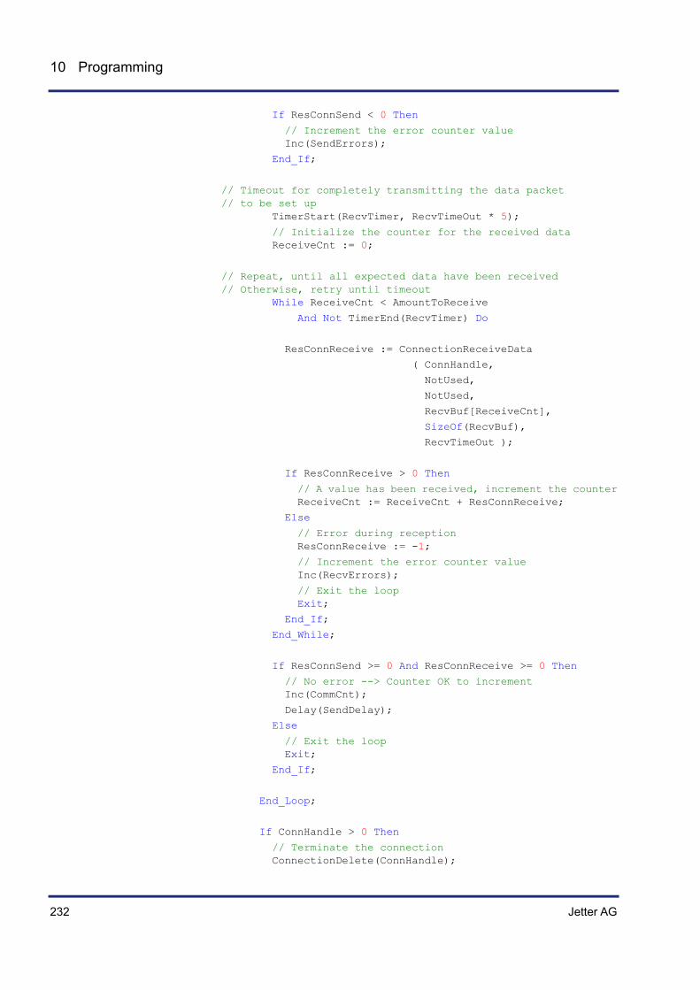
232 Jetter AG
10 Programming
If ResConnSend < 0 Then
// Increment the error counter value Inc(SendErrors);
End_If;
// Timeout for completely transmitting the data packet // to be set up TimerStart(RecvTimer, RecvTimeOut * 5);
// Initialize the counter for the received data ReceiveCnt := 0;
// Repeat, until all expected data have been received // Otherwise, retry until timeout While ReceiveCnt < AmountToReceive
And Not TimerEnd(RecvTimer) Do
ResConnReceive := ConnectionReceiveData
( ConnHandle,
NotUsed,
NotUsed,
RecvBuf[ReceiveCnt],
SizeOf(RecvBuf),
RecvTimeOut );
If ResConnReceive > 0 Then
// A value has been received, increment the counter ReceiveCnt := ReceiveCnt + ResConnReceive;
Else
// Error during reception ResConnReceive := -1;
// Increment the error counter value Inc(RecvErrors);
// Exit the loop Exit;
End_If;
End_While;
If ResConnSend >= 0 And ResConnReceive >= 0 Then
// No error --> Counter OK to increment Inc(CommCnt);
Delay(SendDelay);
Else
// Exit the loop Exit;
End_If;
End_Loop;
If ConnHandle > 0 Then
// Terminate the connection ConnectionDelete(ConnHandle);

Jetter AG 233
JVM-104 Programming
// Handle is no longer valid ConnHandle := 0;
Trace('Connection closed.$n');
End_If;
End_If;
// Wait shortly for another connection to be tried Delay(T#3s);
End_While;
Else
Trace('ConnectionInitialize() failed, client stopped !$n');
End_If;
End_Task;
Server (see page 226)
Related topics


Jetter AG 235
JVM-104 Automatic copying of controller data
11 Automatic copying of controller data
This chapter describes the Autostart feature which lets you copy data within the JVM-104. To this end, you can create a command file which is then stored along with the data to a USB flash drive. This command file is then automatically processed when the USB flash drive is inserted.
The Autostart function executes the following functions:
Creating directories Deleting directories Copying files Deleting files
There are the following main application scopes for the Autostart function:
Where remote control is not possible Where there is no PC on site Where the operator is not able or should not be allowed to make
modifications to the plant The following actions can be taken using the Autostart function:
Modification to the application program Modification to the application data Modification to the controller configuration Updating the operating system (JVM-104)
For automatic copying of controller data, the following prerequisites must be fulfilled:
The programmer is familiar with the file system.
In this description, Complete Name means the name of the file or directory including the complete path.
Topic Page How it works ............................................................................................... 236 autostart.bat - Structure .............................................................................. 240 Data files ..................................................................................................... 243
Introduction
Functions within the local file system
Areas of application
Prerequisites
Definition
Contents

236 Jetter AG
11 Automatic copying of controller data
11.1 How it works
This chapter describes how to load and execute the Autostart function.
Topic Page Loading the Autostart function .................................................................... 237 Executing the Autostart function ................................................................. 238 Terminating the Autostart mode .................................................................. 239
Introduction
Contents

Jetter AG 237
JVM-104 Automatic copying of controller data
Loading the Autostart function
The Autostart function can only be executed while the JVM-104 is booting (i.e. after startup).
You have created the command file and stored it to the respective directory.
Value Comment
File name autostart.bat All lower case letters
Directory - USB \USB\ Root directory on the USB flash drive
To load the Autostart function, proceed as follows:
Step Action
1 Switch the device OFF.
2 Insert the USB flash drive into the USB port.
3 Switch the device ON.
Result: The device boots and loads the Autostart file.
Introduction
Prerequisites
Loading the Autostart function

238 Jetter AG
11 Automatic copying of controller data
Executing the Autostart function
During the boot process in Autostart mode the device executes the commands contained in the command file.
When executing Autostart commands, the OS of the JVM-104 proceeds as follows:
Step Description
1 The device loads the file \USB\autostart.bat from the USB flash drive.
2 ... n The device processes the commands in ascending order.
Introduction
Executing the Autostart function
Jetter AG 239
JVM-104 Automatic copying of controller data
Terminating the Autostart mode
The last command in the file autostart.bat terminates the Autostart mode.
As an option, you can trigger a reset. To this end, enter the following command as last line into the command file: del \System\reset.exe.
To terminate the Autostart mode, proceed as follows:
Step Action
1 Remove the USB flash drive.
Introduction
Restart
Terminating the Autostart mode

240 Jetter AG
11 Automatic copying of controller data
11.2 autostart.bat - Structure
This chapter covers the structure of the file autostart.bat and the available commands.
The command file is a text file with command and comment lines:
You can insert blank lines as required. Start comment lines by REM.
Topic Page Available commands ................................................................................... 241 Example of a command file......................................................................... 242
Introduction
File structure
Contents

Jetter AG 241
JVM-104 Automatic copying of controller data
Available commands
In these sections you can specify commands which are then executed by the Autostart function.
The Autostart function processes the commands in descending order. Furthermore, this function lets you insert jumps into the processing order. A jump is defined by the keyword goto and a destination. The destination must be preceded by a colon (:).
A simple jump is defined as follows: goto end skipped block :end
A conditional jump is defined as follows: if condition goto end skipped block :end
The syntax of these commands is in line with the standard Windows® command line syntax. For more information on the command syntax refer to http://msdn.microsoft.com/en-us/library/ee499728%28v=winembedded.60%29.aspx A command listing can be found here
Introduction
Processing commands
Available commands
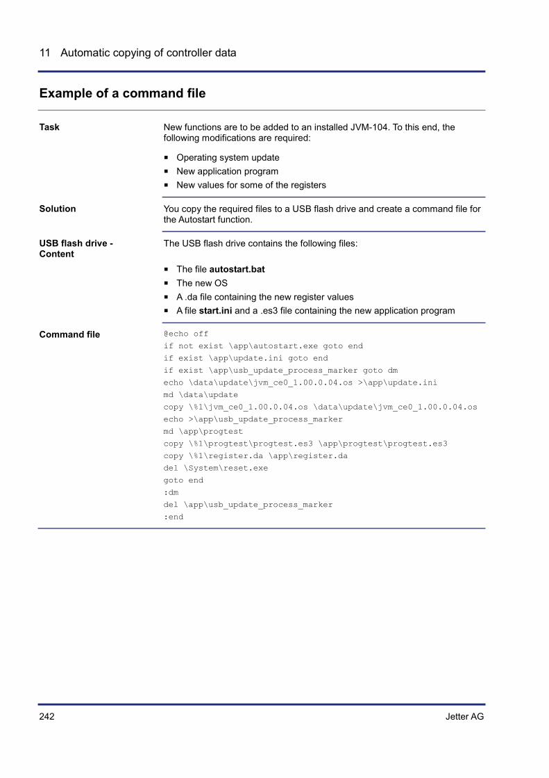
242 Jetter AG
11 Automatic copying of controller data
Example of a command file
New functions are to be added to an installed JVM-104. To this end, the following modifications are required:
Operating system update New application program New values for some of the registers
You copy the required files to a USB flash drive and create a command file for the Autostart function.
The USB flash drive contains the following files:
The file autostart.bat The new OS A .da file containing the new register values A file start.ini and a .es3 file containing the new application program
@echo off
if not exist \app\autostart.exe goto end
if exist \app\update.ini goto end
if exist \app\usb_update_process_marker goto dm
echo \data\update\jvm_ce0_1.00.0.04.os >\app\update.ini
md \data\update
copy \%1\jvm_ce0_1.00.0.04.os \data\update\jvm_ce0_1.00.0.04.os
echo >\app\usb_update_process_marker
md \app\progtest
copy \%1\progtest\progtest.es3 \app\progtest\progtest.es3
copy \%1\register.da \app\register.da
del \System\reset.exe
goto end
:dm
del \app\usb_update_process_marker
:end
Task
Solution
USB flash drive - Content
Command file

Jetter AG 243
JVM-104 Automatic copying of controller data
11.3 Data files
This chapter covers the data file containing register and flag values to be read by the device.
Topic Page File format ................................................................................................... 244 Automatically loading data file information ................................................. 245
Introduction
Contents
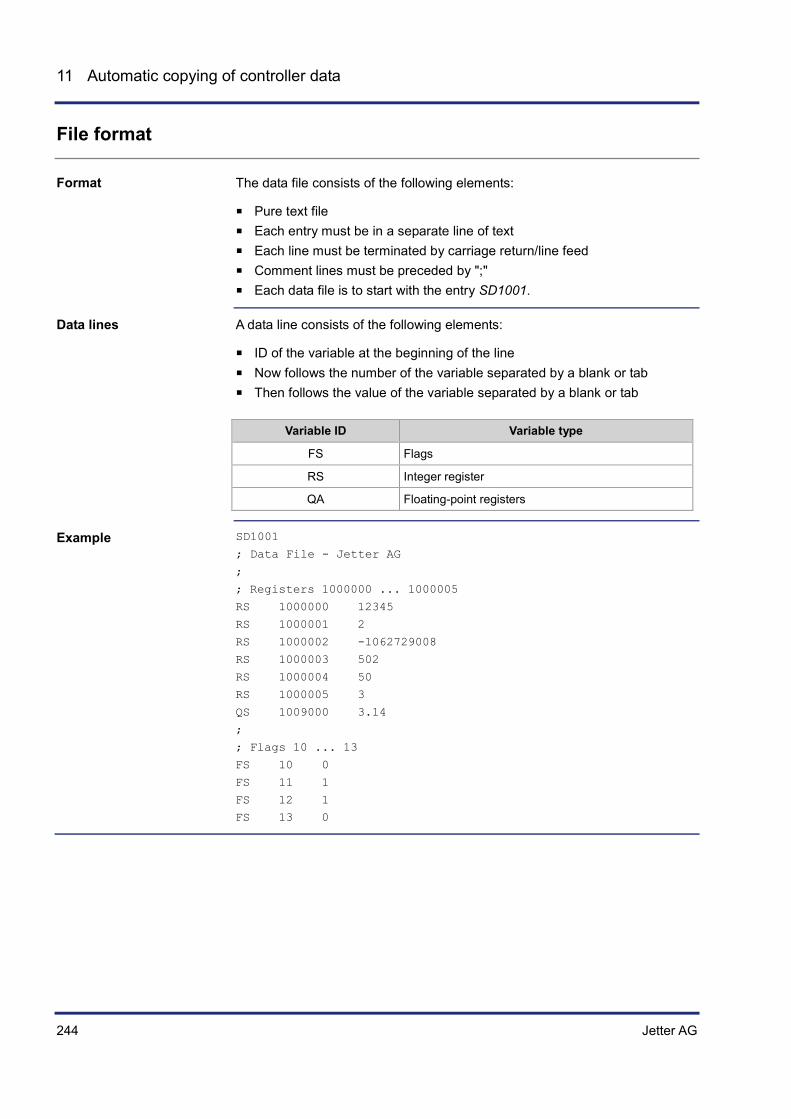
244 Jetter AG
11 Automatic copying of controller data
File format
The data file consists of the following elements:
Pure text file Each entry must be in a separate line of text Each line must be terminated by carriage return/line feed Comment lines must be preceded by ";" Each data file is to start with the entry SD1001.
A data line consists of the following elements:
ID of the variable at the beginning of the line Now follows the number of the variable separated by a blank or tab Then follows the value of the variable separated by a blank or tab
Variable ID Variable type
FS Flags
RS Integer register
QA Floating-point registers
SD1001
; Data File - Jetter AG
;
; Registers 1000000 ... 1000005
RS 1000000 12345
RS 1000001 2
RS 1000002 -1062729008
RS 1000003 502
RS 1000004 50
RS 1000005 3
QS 1009000 3.14
;
; Flags 10 ... 13
FS 10 0
FS 11 1
FS 12 1
FS 13 0
Format
Data lines
Example

Jetter AG 245
JVM-104 Automatic copying of controller data
Automatically loading data file information
The JVM-104 is able to retrieve a data file before the application program is launched.
The data file must be named register.da and stored to the folder app.
The table below shows how the device retrieves data file information:
Step Description
1 If the data file register.da has been stored to the folder app, the device detects this file on its next launch.
2 The device retrieves the file.
3 The device maps the values to the registers.
4 Once the device has retrieved the file, it deletes the data file.
5 The device loads the application program.
Mechanical operation
Prerequisites
Procedure


Jetter AG 247
JVM-104 Operating system update
12 Operating system update
Jetter AG are continuously striving to enhance the operating systems for their HMIs. Enhancing means adding new features, upgrading existing functions and fixing bugs. This chapter describes how to carry out operating system updates.
You can download operating systems from the Jetter AG homepage http://www.jetter.de. You get to the OS files for download at Mobile Automation - Support - Downloads or by clicking on the quick link Operating System Download on the website of the corresponding HMI.
Topic Page Updating the operating system of an HMI .................................................. 248
Introduction
Downloading an operating system
Contents

248 Jetter AG
12 Operating system update
12.1 Updating the operating system of an HMI
This chapter describes how to update the OS of the JVM-104. There are several options to transfer the OS file to the device:
From within the programming tool JetSym Via FTP connection Via JCM system Via directory \App
Topic Page OS update by means of JetSym ................................................................. 249 Operating system update via FTP .............................................................. 250 Operating system update via USB .............................................................. 251 OS update via website of the device .......................................................... 254 Operating system update via \App .............................................................. 256
Introduction
Contents
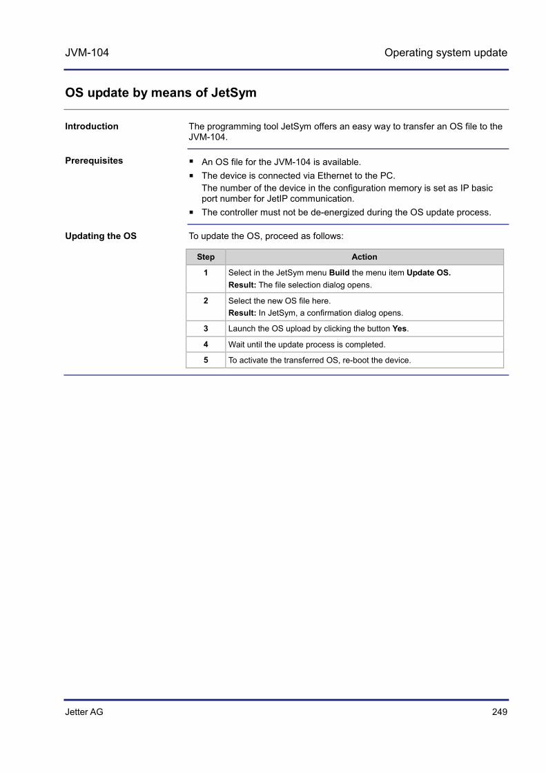
Jetter AG 249
JVM-104 Operating system update
OS update by means of JetSym
The programming tool JetSym offers an easy way to transfer an OS file to the JVM-104.
An OS file for the JVM-104 is available. The device is connected via Ethernet to the PC.
The number of the device in the configuration memory is set as IP basic port number for JetIP communication.
The controller must not be de-energized during the OS update process.
To update the OS, proceed as follows:
Step Action
1 Select in the JetSym menu Build the menu item Update OS. Result: The file selection dialog opens.
2 Select the new OS file here. Result: In JetSym, a confirmation dialog opens.
3 Launch the OS upload by clicking the button Yes.
4 Wait until the update process is completed.
5 To activate the transferred OS, re-boot the device.
Introduction
Prerequisites
Updating the OS

250 Jetter AG
12 Operating system update
Operating system update via FTP
Using an FTP client an OS file can be transferred to the device JVM-104.
An OS file for the JVM-104 is available. An FTP connection to the device has been established. The operating system of the JVM-104 is running. The controller must not be de-energized during the OS update process.
To update the OS, proceed as follows:
Step Action
1 Establish an FTP connection to the JVM-104.
2 Log in with administrator rights.
3 Navigate to the directory \App.
4 Transfer the OS file.
5 Wait until the transfer process is completed.
6 Use a text editor and create on your PC a configuration file named config.ini.
7 Enter into this file the path and the name of the OS file on the device, e.g. \app\jvm_ce0_1.00.0.07.os.
8 Copy this file into the directory \App.
9 Clear the FTP connection.
10 To activate the transferred OS, re-boot the device.
11 The new OS is being installed. Wait at least one minute.
12 Restart the device.
Introduction
Prerequisites
Updating the OS

Jetter AG 251
JVM-104 Operating system update
Operating system update via USB
A USB flash drive lets you transfer an OS file to the device JVM-104.
An OS file for the JVM-104 is available. The operating system of the JVM-104 as of version 4.01.0.44 is running. The controller must not be de-energized during the OS update process.
The batch file autostart.bat must have the following contents: @echo off
if not exist \app\autostart.exe goto end
if exist \app\update.ini goto end
if exist \app\usb_update_process_marker goto dm
\app\sys\testregistry AUTOSTART AutoCopy == 0
if ERRORLEVEL 1 goto end
echo \data\update\jvm_ce0_1.00.0.04.os >\app\update.ini
if not exist \data\update md \data\update
@cmd /c start \App\sys\jvcm_si 102
copy \%1\jvm_ce0_1.00.0.04.os \data\update\jvm_ce0_1.00.0.04.os
echo >\app\usb_update_process_marker
del \System\reset.exe
goto end
:dm
del \app\usb_update_process_marker
:end
When using devices without any operating keys, you must delete the following commands from the batch file autostart.bat. \app\sys\testregistry AUTOSTART AutoCopy == 0
if ERRORLEVEL 1 goto end
To update the OS of devices being equipped with keys, proceed as follows:
Step Action
1 Copy the OS file to your USB flash drive. This drive must be FAT formatted.
2 Create a batch file on the USB flash drive and name it autostart.bat. Contents of the batch file: See above.
3 Replace all entries jvm_ce0_1.00.0.04 with the actual name of the OS file.
4 Switch the device JVM-104 OFF.
5 Insert the USB flash drive into the JVM-104.
6 Switch the device JVM-104 ON.
7 Simultaneously press the first and the third key before starting the application program.
Introduction
Prerequisites
Contents of the batch file
Updating the OS

252 Jetter AG
12 Operating system update
Step Action
The device switches to update mode and displays the following dialog text: Please select update source: Press [F1] for USB update | Press [F3] for SD update
8 Press the corresponding key.
The device continues the dialog as follows: Preparing update Please do not remove the update device Update will be performed after restart
About 10 seconds later the device automatically launches the update process.
When the update is completed, the device displays the following text: Update completed Please wait
Now, the device automatically reboots and starts the application.
To update the OS of devices without keys, proceed as follows:
Step Action
1 Copy the OS file to your USB flash drive. This drive must be FAT formatted.
2 Create a batch file on the USB flash drive and name it autostart.bat. Contents of the batch file: See above.
3 Replace all entries jvm_ce0_1.00.0.04 with the actual name of the OS file.
4 Insert the USB flash drive into the JVM-104. This can be done while the device is running.
Result: The OS is being installed.
The table below lists the update steps in chronological order:
Step Description
1 The files are transferred.
2 The device is reset.
3 The files are installed.
4 The device is reset.
5 The application appears.
Update - Chronological order

Jetter AG 253
JVM-104 Operating system update
The update process is documented in the file \App\update.log.
Log file for documentation purposes

254 Jetter AG
12 Operating system update
OS update via website of the device
The device web site in Internet Explorer shows all properties and version numbers of your device. It also lets you configure the Ethernet and the CANopen® interfaces.
To have the device web site displayed on your PC, enter the current IP address of the device in the Internet Explorer. Example:
To enter the IP address in the range of exceptions of the Internet Explorer, proceed as follows:
Step Action
1 Click menu item Tools and open the dialog Internet options.
2 Go to tab Connections and click the button LAN settings.
3 In section Proxy Server click the button Advanced.
The dialog Proxy Settings opens.
4 In the Exceptions pane of the dialog Proxy Settings, enter IP address 192.168.*, as is shown in the illustration below.
Introduction
Accessing the device web site
Prerequisites

Jetter AG 255
JVM-104 Operating system update
The page Update lets you select an OS file (Browse...) and copy it to the device (Upload).
If you click the button Last Update Log, the history of the last update is displayed. This lets you detect possible errors.
Update page
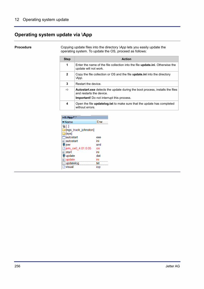
256 Jetter AG
12 Operating system update
Operating system update via \App
Copying update files into the directory \App lets you easily update the operating system. To update the OS, proceed as follows:
Step Action
1 Enter the name of the file collection into the file update.ini. Otherwise the update will not work.
2 Copy the file collection or OS and the file update.ini into the directory \App.
3 Restart the device.
Autostart.exe detects the update during the boot process, installs the files and restarts the device. Important! Do not interrupt this process.
4 Open the file updatelog.txt to make sure that the update has completed without errors.
Procedure

Jetter AG 257
JVM-104 Application program
13 Application program
This chapter describes how to store the application program in JVM-104. The user determines the program that is to be executed.
This chapter requires knowledge on how to create application programs in JetSym and how to transmit them via the file system of the JVM-104.
Topic Page Application program - Default path ............................................................. 258 Loading an application program ................................................................. 259
Introduction
Required programmer's skills
Contents

258 Jetter AG
13 Application program
Application program - Default path
When uploading the application program from JetSym to the controller, this program is stored as a file to the internal flash disk. The device enters the path and file name into the file \App\start.ini.
In the directory \App, JetSym, by default, creates a subdirectory and assigns the project name to it. Then, JetSym stores the application program to this subdirectory assigning the extension .es3 to it. Path and file names are always converted into lower case letters.
This file is a text file with one section holding two entries:
Element Description
[Startup] Section name
Project Path to the application program file, relative to \App
Program Name of the application program file Example:
[Startup]
Project = test_program
Program = test_program.es3
Result: The application program is loaded from the file \App\test_program\test_program.es3.
Introduction
Path and file name
\App\start.ini - Structure

Jetter AG 259
JVM-104 Application program
Loading an application program
At reboot of the application program via JetSym or booting the JVM-104, the application program is loaded and executed via the file system.
The application program is loaded by the JVM-104's OS as follows:
Step Description
1 The OS reads the file /App/start.ini from the internal flash disk.
2 The OS evaluates the Project entry. It contains the path leading to the application program file.
3 The OS evaluates the Program entry. It contains the program name.
4 The OS loads the application program from the file <Project>\<Program>.
Introduction
Loading process


Jetter AG 261
JVM-104 Quick reference JVM-104
14 Quick reference JVM-104
Corresponding OS version
This quick reference summarizes in brief the registers and flags of the HMI JVM-104 running OS version 4.01.
Default address on the CANopen® bus
Default address of the JVM-104: Node ID: 127 (0x7F)
Maximum number of CANopen® interfaces
Maximum number of CAN interfaces: 2 CANMAX: 1
Maximum number of SAE J1939 interfaces
Maximum number of CAN interfaces: 1 CANMAX: 1
Registers - General overview
100000 ... 100999 Electronic Data Sheet (EDS) 101000 … 101999 Configuration 104000 ... 104999 Ethernet 106000 ... 106999 CAN
108000 ... 108999 CPU/backplane
200000 ... 209999 General system registers 210000 ... 219999 Application program 230000 ... 239999 Networking via JetIP 260000 ... 269999 RemoteScan 270000 ... 279999 Modbus/TCP 290000 ... 299999 E-mail 310000 ... 319999 File system/data files 350000 ... 359999 User-programmable IP interface 360000 ... 369999 Display
1000000 ... 1029999 Application registers (remanent)
I/Os - General overview
Input keys 361000 ... 361007 Bit-coded map of input keys
Flags - General overview
0 ... 255 Application flags (remanent) 256 ... 2047 Overlaid by registers R 1000000 through 1000055 2048 ... 2303 Special flags
Electronic Data Sheet (EDS)
100500 Interface (0 = CPU, 4 = Base board)
100600 Internal version number 100601 Module ID 100602 ... 100612
Module name (register string)
100613 PCB revision 100614 PCB options
Production 100700 Internal version number 100701 ... 100707
Serial number (register string)
100708 Day 100709 Month 100710 Year 100711 TestNum. 100712 TestRev.
Features 100800 Internal version number 100801 MAC Address (Jetter) 100802 MAC address (device)
Electronic name plate (device as a whole)
Production 100900 Internal version number 100901 ... 100907
Serial number (register string)
100708 Day 100709 Month 100710 Year
100950 Internal version number 100951 Module ID 100952 ... 100962
Module name (register string)
100965 Config ID 100966 Vendor ID 100967 Variant ID 100968 Type ID 100992 Navision ID 100993 FBG version
Configuration
From system configuration
101100 IP address (rw - remanent) 101101 Subnet mask (rw - remanent) 101102 Default gateway (rw - remanent)
Used by the system
101200 IP address 101201 Subnet mask 101202 Default gateway
Ethernet
IP
104531 Current IP address (rw - temporary) 104532 Current subnet mask (rw - temporary) 104533 Current default gateway (rw - temporary)
CAN
106000 Baud rate CAN 1 106001 Node ID CAN 1 106100 Baud rate CAN 2 106101 Node ID CAN 2
Flash memory
107501 30: Read present flash disk statistics 99: Clear flash disk statistics
107510 Available sectors 107511 Used sectors 107512 Blocked sectors

262 Jetter AG
14 Quick reference JVM-104
107513 Free sectors 107520 Size of the flash disk in bytes 107521 Used memory in bytes 107522 Blocked memory in bytes 107523 Free memory in bytes
CPU hardware
108015 Voltage of backup battery (e.g. for clock) 0 = Data not valid
1 = Supply voltage is OK
Once the power supply has been restored, enter 1 into this register.
System information
108500 ... 108509
JetVM-DII version string
108510 ... 108519
Version string of the host application
108520 ... 108529
File name of the host application
108530 ... 108539
OS version (string)
108570 CPU type 108571 Number of CPUs 108573 Physical RAM 108574 Free physical RAM 108575 Memory utilization (in %) 108581 Screen width (in pixels) 108582 Screen height (in pixels) 108590 HID version
USB flash drive
109000 Bit 0 = 1: Data medium is available Bit 1 = 1: Data medium is ready
109001 1 = Data medium is write-protected (only valid if R 109000 = 3)
109002 Size in MBytes
General system registers
200000 OS version (major * 100 + minor) 200001 Application program is running (bit 0 = 1) 200008 Error register (identical with 210004) Bit 8: Illegal jump
Bit 9: Illegal call
Bit 10: Illegal index
Bit 11: Illegal opcode
Bit 12: Division by 0
Bit 13: Stack overflow
Bit 14: Stack underflow
Bit 15: Illegal stack
Bit 16: Error when loading the application program
Bit 24: Timeout - Cycle time
Bit 25: Timeout - Task lock
Bit 31: Unknown error
200168 Bootloader version (IP format) 200169 OS version (IP format) 201000 Runtime register in milliseconds (rw)
201001 Runtime register in seconds (rw) 201002 Runtime register in R 201003 Units (rw)
201003 * 10 ms units for R 201002 (rw) 201004 Runtime register in milliseconds (ro) 201005 Runtime registers in microseconds (ro) 202930 Web status (bit-coded)
Bit 0 = 1: FTP server available
Bit 1 = 1: HTTP-server available
Bit 2 = 1: E-mail available
Bit 3 = 1: Data file function available
Bit 4 = 1: Modbus/TCP has been licensed
Bit 5 = 1: Modbus/TCP available
Bit 6 = 1: Ethernet/IP available
202960 Password for system command register (0x424f6f74) 202961 System command register 202980 Error history: Number of entries 202981 Error history: Index 202982 Error history: Entry
203000 Interface monitoring: JetIP 203005 Interface monitoring: Debug server 203100 ... 203107
32-bit overlaying - Flag 0 ... 255
203108 ... 203123
16-bit overlaying - Flag 0 ... 255
203124 ... 203131
32-bit overlaying - Flag 2048 ... 2303
203132 ... 203147
16-bit overlaying - Flag 2048 ... 2303
209700 System logger: Global enable 209701 ... 209739
Enabling system components
Application program
210000 Application program is running (bit 0 = 1) 210001 JetVM version 210004 Error register (bit-coded) Bit 8: Illegal jump
Bit 9: Illegal call
Bit 10: Illegal index
Bit 11: Illegal opcode
Bit 12: Division by 0
Bit 13: Stack overflow
Bit 14: Stack underflow
Bit 15: Illegal stack
Bit 16: Error when loading the application program
Bit 24: Timeout - cycle time
Bit 25: Timeout - task lock
Bit 31: Unknown error
210006 Highest task number 210007 Minimum program cycle time 210008 Maximum program cycle time 210009 Current program cycle time 210011 Current task number 210050 Current program position within an execution unit 210051 ID of the execution unit being processed 210056 Desired total cycle time in µs
210057 Calculated total cycle time in µs 210058 Maximum time slice per task in µs 210060 Task ID (for R210061)

Jetter AG 263
JVM-104 Quick reference JVM-104
210061 Priority for task [R210060] 210063 Length of scheduler table
210064 Index in scheduler table 210065 Task ID in scheduler table 210070 Task ID (for R210071) 210071 Timer number (0 ... 31) 210072 Manual triggering of a timer event (bit-coded) 210073 End of cyclic task (task ID)
210074 Command for cyclic tasks 210075 Number of timers 210076 Timer number (for R210077) 210077 Timer value in milliseconds 210100 ... 210199
Task state
210400 ... 210499
Task - Program address
210600 Task ID of a cyclical task (for R210601) 210601 Processing time of a cyclical task in per mil figure 210609 Task lock timeout in ms -1: Monitoring disabled
210610 Timeout (bit-coded) Bit 0 -> Timer 0, etc.
Networking via JetIP
230000 JetIP/TCP server: Number of open connections 230001 JetIP/TCP server: Mode 230002 JetIP/TCP server: Time
232708 Timeout in milliseconds 232709 Response time in milliseconds 232710 Amount of network errors 232711 Error code of last access 0 = No error
1 = Timeout
3 = Error message of the remote station
5 = Invalid network address
6 = Invalid amount of registers
7 = Invalid interface number
232717 Max. number of retries 232718 Number of retries
Modbus/TCP
272702 Register offset 272704 Input offset 272705 Output offset 278000 ... 278999
16-bit I/O registers overlaid by virtual I/Os 20001 ... 36000
292932 IP address of the SMTP server 292933 IP address of the POP3 server 292934 Port number of the SMTP server 292935 Port number of POP3 server 292937 Status of e-mail processing 292938 Task ID - E-mail
File system/data file function
312977 Status of file operation 312978 Task ID
User-programmable IP interface
Reading out the connection list 350000 Last result (-1 = no connection selected) 350001 1 = Client; 2 = Server 350002 1 = UDP; 2 = TCP 350003 IP address 350004 Port number 350005 Connection state 350006 Number of sent bytes 350007 Number of received bytes
Application registers
1000000 ... 1005999
32-bit integer (remanent)
CAN-PRIM registers
200010500 CAN-PRIM status 200010501 CAN-PRIM command register 200010502 Message box number 200010503 FIFO buffer occupancy 200010504 FIFO data 200010506 Global receiving mask 200010507 Global receive ID 200010510 Box status register 200010511 Box configuration register 200010512 CAN ID 200010513 Number of data bytes 200010514 ... 200010521
Data bytes
Display
Input keys 361000 ... 361007
Bit-coded map of input keys e.g. bit 0: 1 = Key 1 is pressed
361000.0 KEY_OK 361000.1 KEY_ESC 361000.2 KEY_DOWN 361000.3 KEY_UP Ignition (IGN) 361100 Bit 0:
0 = Ignition ON 1 = Ignition OFF
Digipot 363000 Present count value 363001 Digipot key 363002 Minimum count value 363003 Maximum count value
Display 364000 Background lighting 364001 Night-lighting of keys 364003 Brightness sensor
Visualization 365100 Language selection according to ID
Special flags for networks
2075 Error in networking via JetIP
Special flags - Interface monitoring
2088 OS flag - JetIP 2089 User flag - JetIP 2098 OS flag - Debug server
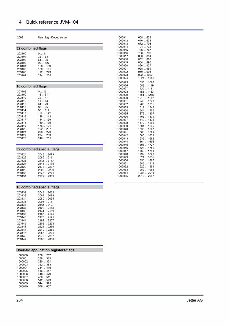
264 Jetter AG
14 Quick reference JVM-104
2099 User flag - Debug server
32 combined flags
203100 0 ... 31 203101 32 ... 63 203102 64 ... 95 203103 96 ... 127 203104 128 ... 159 203105 160 ... 191 203106 192 ... 223 203107 224 ... 255
16 combined flags
203108 0 ... 15 203109 16 ... 31 203110 32 ... 47 203111 48 ... 63 203112 64 ... 79 203113 80 ... 95 203114 96 ... 111 203115 112 ... 127 203116 128 ... 143 203117 144 ... 159 203118 160 ... 175 203119 176 ... 191 203120 192 ... 207 203121 208 ... 223 203122 224 ... 239 203123 240 ... 255
32 combined special flags
203124 2048 ... 2079 203125 2080 ... 2111 203126 2112 ... 2143 203127 2144 ... 2175 203128 2176 ... 2207 203129 2208 ... 2239 203130 2240 ... 2271 203131 2272 ... 2303
16 combined special flags
203132 2048 ... 2063 203133 2064 ... 2079 203134 2080 ... 2095 203135 2096 ... 2111 203136 2112 ... 2127 203137 2128 ... 2143 203138 2144 ... 2159 203139 2160 ... 2175 203140 2176 ... 2191 203141 2192 ... 2207 203142 2208 ... 2223 203143 2224 ... 2239 203144 2240 ... 2255 203145 2256 ... 2271 203146 2272 ... 2287 203147 2288 ... 2303
Overlaid application registers/flags
1000000 256 ... 287 1000001 288 ... 319 1000002 320 ... 351 1000003 352 ... 383 1000004 384 ... 415 1000005 416 ... 447 1000006 448 ... 479 1000007 480 ... 511 1000008 512 ... 543 1000009 544 ... 575 1000010 576 ... 607
1000011 608 ... 639 1000012 640 ... 671 1000013 672 ... 703 1000014 704 ... 735 1000015 736 ... 767 1000016 768 ... 799 1000017 800 ... 831 1000018 832 ... 863 1000019 864 ... 895 1000020 896 ... 927 1000021 928 ... 959 1000022 960 ... 991 1000023 992 ... 1023 1000024 1024 ... 1055 1000025 1056 ... 1087 1000026 1088 ... 1119 1000027 1120 ... 1151 1000028 1152 ... 1183 1000029 1184 ... 1215 1000030 1216 ... 1247 1000031 1248 ... 1279 1000032 1280 ... 1311 1000033 1312 ... 1343 1000034 1344 ... 1375 1000035 1376 ... 1407 1000036 1408 ... 1439 1000037 1440 ... 1471 1000038 1472 ... 1503 1000039 1504 ... 1535 1000040 1536 ... 1567 1000041 1568 ... 1599 1000042 1600 ... 1631 1000043 1632 ... 1663 1000044 1664 ... 1695 1000045 1696 ... 1727 1000046 1728 ... 1759 1000047 1760 ... 1791 1000048 1792 ... 1823 1000049 1824 ... 1855 1000050 1856 ... 1887 1000051 1888 ... 1919 1000052 1920 ... 1951 1000053 1952 ... 1983 1000054 1984 ... 2015 1000055 2016 ... 2047
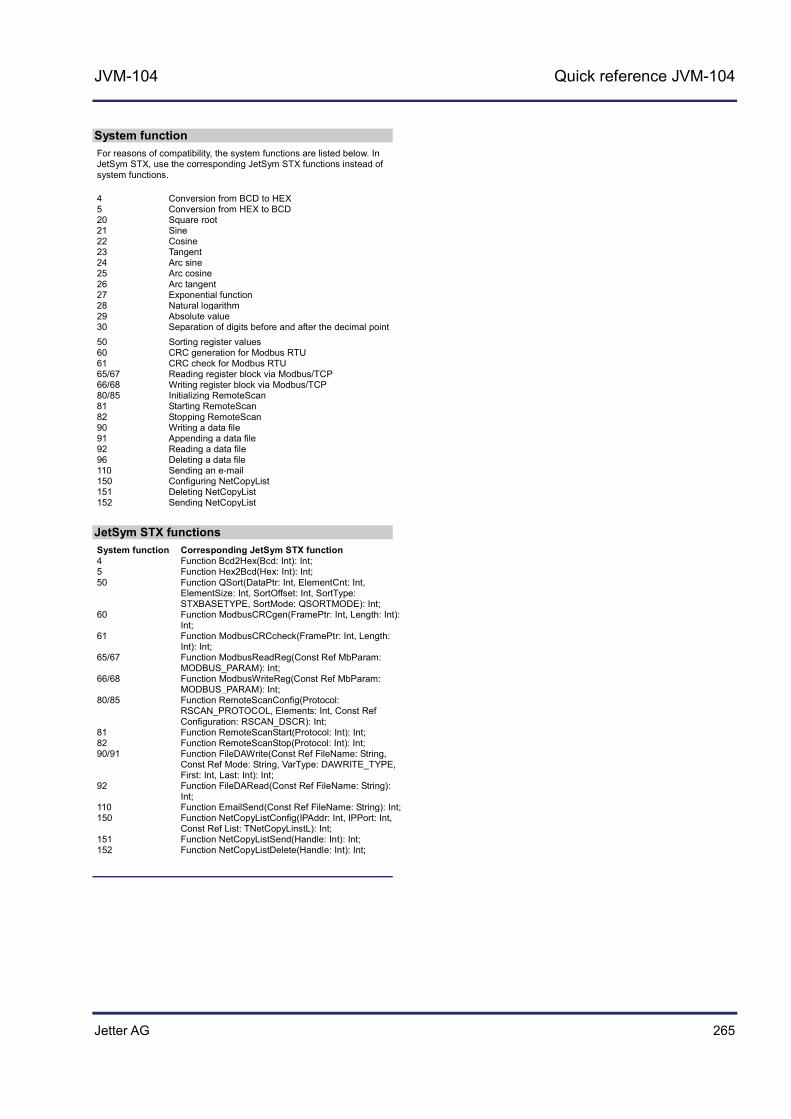
Jetter AG 265
JVM-104 Quick reference JVM-104
System function
For reasons of compatibility, the system functions are listed below. In JetSym STX, use the corresponding JetSym STX functions instead of system functions.
4 Conversion from BCD to HEX 5 Conversion from HEX to BCD 20 Square root 21 Sine 22 Cosine 23 Tangent 24 Arc sine 25 Arc cosine 26 Arc tangent 27 Exponential function 28 Natural logarithm 29 Absolute value 30 Separation of digits before and after the decimal point 50 Sorting register values 60 CRC generation for Modbus RTU 61 CRC check for Modbus RTU 65/67 Reading register block via Modbus/TCP 66/68 Writing register block via Modbus/TCP 80/85 Initializing RemoteScan 81 Starting RemoteScan 82 Stopping RemoteScan 90 Writing a data file 91 Appending a data file 92 Reading a data file 96 Deleting a data file 110 Sending an e-mail 150 Configuring NetCopyList 151 Deleting NetCopyList 152 Sending NetCopyList
JetSym STX functions
System function Corresponding JetSym STX function 4 Function Bcd2Hex(Bcd: Int): Int; 5 Function Hex2Bcd(Hex: Int): Int; 50 Function QSort(DataPtr: Int, ElementCnt: Int,
ElementSize: Int, SortOffset: Int, SortType: STXBASETYPE, SortMode: QSORTMODE): Int;
60 Function ModbusCRCgen(FramePtr: Int, Length: Int): Int;
61 Function ModbusCRCcheck(FramePtr: Int, Length: Int): Int;
65/67 Function ModbusReadReg(Const Ref MbParam: MODBUS_PARAM): Int;
66/68 Function ModbusWriteReg(Const Ref MbParam: MODBUS_PARAM): Int;
80/85 Function RemoteScanConfig(Protocol: RSCAN_PROTOCOL, Elements: Int, Const Ref Configuration: RSCAN_DSCR): Int;
81 Function RemoteScanStart(Protocol: Int): Int; 82 Function RemoteScanStop(Protocol: Int): Int; 90/91 Function FileDAWrite(Const Ref FileName: String,
Const Ref Mode: String, VarType: DAWRITE_TYPE, First: Int, Last: Int): Int;
92 Function FileDARead(Const Ref FileName: String): Int;
110 Function EmailSend(Const Ref FileName: String): Int; 150 Function NetCopyListConfig(IPAddr: Int, IPPort: Int,
Const Ref List: TNetCopyLinstL): Int; 151 Function NetCopyListSend(Handle: Int): Int; 152 Function NetCopyListDelete(Handle: Int): Int;

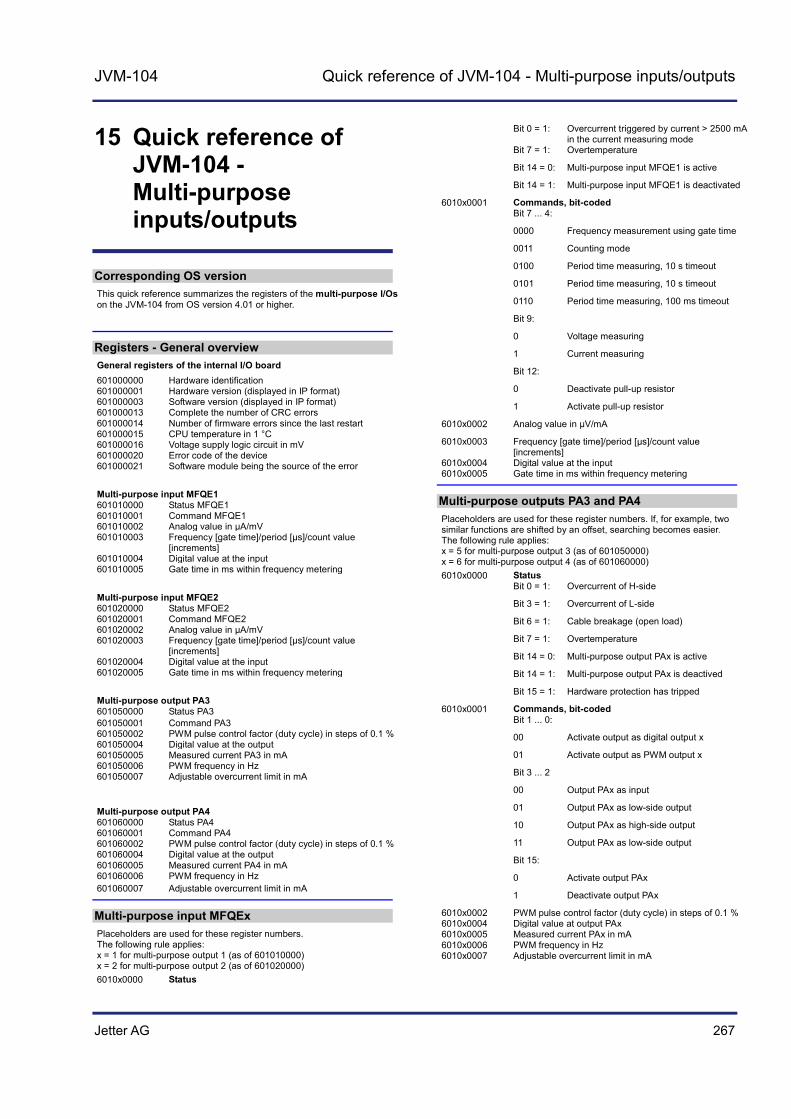
Jetter AG 267
JVM-104 Quick reference of JVM-104 - Multi-purpose inputs/outputs
15 Quick reference of JVM-104 - Multi-purpose inputs/outputs
Corresponding OS version
This quick reference summarizes the registers of the multi-purpose I/Os on the JVM-104 from OS version 4.01 or higher.
Registers - General overview
General registers of the internal I/O board 601000000 Hardware identification 601000001 Hardware version (displayed in IP format) 601000003 Software version (displayed in IP format) 601000013 Complete the number of CRC errors 601000014 Number of firmware errors since the last restart 601000015 CPU temperature in 1 °C 601000016 Voltage supply logic circuit in mV 601000020 Error code of the device 601000021 Software module being the source of the error Multi-purpose input MFQE1 601010000 Status MFQE1 601010001 Command MFQE1 601010002 Analog value in µA/mV 601010003 Frequency [gate time]/period [µs]/count value
[increments] 601010004 Digital value at the input 601010005 Gate time in ms within frequency metering Multi-purpose input MFQE2 601020000 Status MFQE2 601020001 Command MFQE2 601020002 Analog value in µA/mV 601020003 Frequency [gate time]/period [µs]/count value
[increments] 601020004 Digital value at the input 601020005 Gate time in ms within frequency metering Multi-purpose output PA3 601050000 Status PA3 601050001 Command PA3 601050002 PWM pulse control factor (duty cycle) in steps of 0.1 % 601050004 Digital value at the output 601050005 Measured current PA3 in mA 601050006 PWM frequency in Hz 601050007 Adjustable overcurrent limit in mA
Multi-purpose output PA4 601060000 Status PA4 601060001 Command PA4 601060002 PWM pulse control factor (duty cycle) in steps of 0.1 % 601060004 Digital value at the output 601060005 Measured current PA4 in mA 601060006 PWM frequency in Hz 601060007 Adjustable overcurrent limit in mA
Multi-purpose input MFQEx
Placeholders are used for these register numbers. The following rule applies: x = 1 for multi-purpose output 1 (as of 601010000) x = 2 for multi-purpose output 2 (as of 601020000)
6010x0000 Status
Bit 0 = 1: Overcurrent triggered by current > 2500 mA in the current measuring mode
Bit 7 = 1: Overtemperature
Bit 14 = 0: Multi-purpose input MFQE1 is active
Bit 14 = 1: Multi-purpose input MFQE1 is deactivated
6010x0001 Commands, bit-coded Bit 7 ... 4:
0000 Frequency measurement using gate time
0011 Counting mode
0100 Period time measuring, 10 s timeout
0101 Period time measuring, 10 s timeout
0110 Period time measuring, 100 ms timeout
Bit 9:
0 Voltage measuring
1 Current measuring
Bit 12:
0 Deactivate pull-up resistor
1 Activate pull-up resistor
6010x0002 Analog value in µV/mA
6010x0003 Frequency [gate time]/period [µs]/count value [increments]
6010x0004 Digital value at the input 6010x0005 Gate time in ms within frequency metering
Multi-purpose outputs PA3 and PA4
Placeholders are used for these register numbers. If, for example, two similar functions are shifted by an offset, searching becomes easier. The following rule applies: x = 5 for multi-purpose output 3 (as of 601050000) x = 6 for multi-purpose output 4 (as of 601060000)
6010x0000 Status Bit 0 = 1: Overcurrent of H-side
Bit 3 = 1: Overcurrent of L-side
Bit 6 = 1: Cable breakage (open load)
Bit 7 = 1: Overtemperature
Bit 14 = 0: Multi-purpose output PAx is active
Bit 14 = 1: Multi-purpose output PAx is deactived
Bit 15 = 1: Hardware protection has tripped
6010x0001 Commands, bit-coded Bit 1 ... 0:
00 Activate output as digital output x
01 Activate output as PWM output x
Bit 3 ... 2
00 Output PAx as input
01 Output PAx as low-side output
10 Output PAx as high-side output
11 Output PAx as low-side output
Bit 15:
0 Activate output PAx
1 Deactivate output PAx
6010x0002 PWM pulse control factor (duty cycle) in steps of 0.1 % 6010x0004 Digital value at output PAx 6010x0005 Measured current PAx in mA 6010x0006 PWM frequency in Hz 6010x0007 Adjustable overcurrent limit in mA

268 Jetter AG
15 Quick reference of JVM-104 - Multi-purpose inputs/outputs
H-bridge PA3H
PA3L
PA4H
PA4L
H-bridge outputs
PA3H Output 1
PA3L Output 1 PA4H Output 2 PA4L Output 2
H-bridge, clockwise rotation: Steps
1 PA3: Activate low-side output: R 601050001 :=0x8005;
2 PA3: Set PWM pulse control factor (duty cycle) to 100 %: R 601050002 := 1000;
3 PA4: Activate high-side output: R 601060001 :=0x8009;
4 PA4: Tastverhältnis z. B. 50 % einstellen: R 601060002 := 500;
H-bridge, anti-clockwise rotation Steps
1 PA4: Activate low-side output: R 601060001 := 0x8005;
2 PA4: Set PWM pulse control factor (duty cycle) to 100 %: R 601060002 := 1000;
3 PA3: Activate high-side output: R 601050001 :=0x8009;
4 PA3: Set pulse control factor (duty cycle) to 50 %: R 601050002 := 500;
Assignment: 12-pin DEUTSCH connector DT06-12S
View on the rear side of the HMI
Pin Description 1 Reference potential (GND)
2 CAN_2_L 3 CAN_2_H 4 Multi-purpose output PA3
5 Multi-purpose output PA4 6 Power supply UB for logic circuits
Voltage: DC 12 V or DC 24 V Maximum current: 2 A
7 Power supply UB_PA for multi-purpose outputs Voltage: DC 12 V or DC 24 V Maximum current: 10 A
8 Ignition 9 CAN_1_L 10 CAN_1_H 11 Multi-purpose input MFQE1 12 Multi-purpose input MFQE2

Jetter AG 269
JVM-104 Appendix
Appendix
This appendix contains electrical and mechanical data, as well as operating data.
Topic Page Interfaces .................................................................................................... 270 Technical data ............................................................................................. 275 Index ........................................................................................................... 284
Introduction
Contents

270 Jetter AG
Appendix
A: Interfaces
The HMI JVM-104 is equipped with the following interfaces:
DEUTSCH connector Ethernet port USB port
The DEUTSCH connector has the following functions:
Power supply of the JVM-104 Power supply for higher load currents Multi-purpose inputs Multi-purpose outputs CANopen® bus interfaces: CAN 1 and CAN 2 Recognition of the ignition
The function of the RJ45 jack is as follows:
Ethernet port to a PC Ethernet port to other devices, such as a controller
The USB port serves the following purposes:
Updating the system via USB flash drive Interface for USB flash drives providing additional memory Interface for USB devices, such as mouse or keyboard
Topic Page Pinout - Overview ........................................................................................ 271
Introduction
DEUTSCH connector
Ethernet port
USB port
Contents

Jetter AG 271
JVM-104 Appendix
Pinout - Overview
This chapter describes the pinout of the connector for the power supply. The diagram shows the pinout of the power supply and ignition connector (viewing the cable side):
1 6
712
The pinout is as follows:
Pin Description Terminal number in vehicles
1 Reference potential (GND) Terminal # 31
6 Power supply UB for logic circuits Voltage: DC 12 V or DC 24 V Current consumption: 2 A max.
Terminal # 30
7 Power supply UB_PA for multi-purpose outputs of the HMI Voltage: DC 12 V or DC 24 V Current consumption: 10 A max.
Terminal # 30
8 Ignition (+) Terminal # 15
Power supply
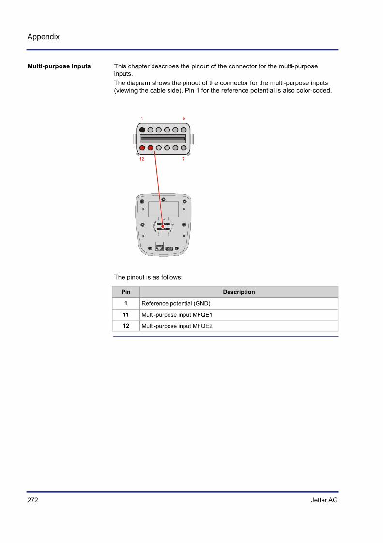
272 Jetter AG
Appendix
This chapter describes the pinout of the connector for the multi-purpose inputs. The diagram shows the pinout of the connector for the multi-purpose inputs (viewing the cable side). Pin 1 for the reference potential is also color-coded.
1 6
712
The pinout is as follows:
Pin Description
1 Reference potential (GND)
11 Multi-purpose input MFQE1
12 Multi-purpose input MFQE2
Multi-purpose inputs

Jetter AG 273
JVM-104 Appendix
This chapter describes the pinout of the connector for the multi-purpose outputs. The diagram shows the pinout of the connector for the multi-purpose outputs and the CAN interface (viewing the cable side). Pin 1 for the reference potential is also color-coded.
1 6
712
The pinout is as follows:
Pin Description
1 Reference potential (GND)
4 Multi-purpose output PA3
5 Multi-purpose output PA4
The H-bridge is assigned to the following outputs:
Multi-purpose output PA3 Multi-purpose output PA4
PA3H
PA3L
PA4H
PA4L
PA3 PA4
Multi-purpose outputs
Pinout of the H-bridge

274 Jetter AG
Appendix
When setting up the program, switch PA3H and PA4L and PA4H and PA3L to the desired direction, that is, anti- clockwise and clockwise.
This chapter describes the pinout of the connector for the CAN interfaces. The diagram shows the pinout of the connector for the CANopen® bus (viewing the cable side). Pin 1 for the reference potential is also color-coded.
1 6
712
The pinout is as follows:
Pin Description
1 Reference potential (GND)
2 CAN_2_L
3 CAN_2_H
9 CAN_1_L
10 CAN_1_H
CAN interfaces
Jetter AG 275
JVM-104 Appendix
B: Technical data
This chapter contains information on electrical and mechanical data, as well as on operating data of the JVM-104.
Topic Page Technical specifications .............................................................................. 276 Multi-purpose inputs/outputs - Technical specifications ............................ 278 Physical dimensions ................................................................................... 281 Operating parameters - Environment and mechanics ................................ 282 Operating parameters - EMC ..................................................................... 283
Introduction
Contents
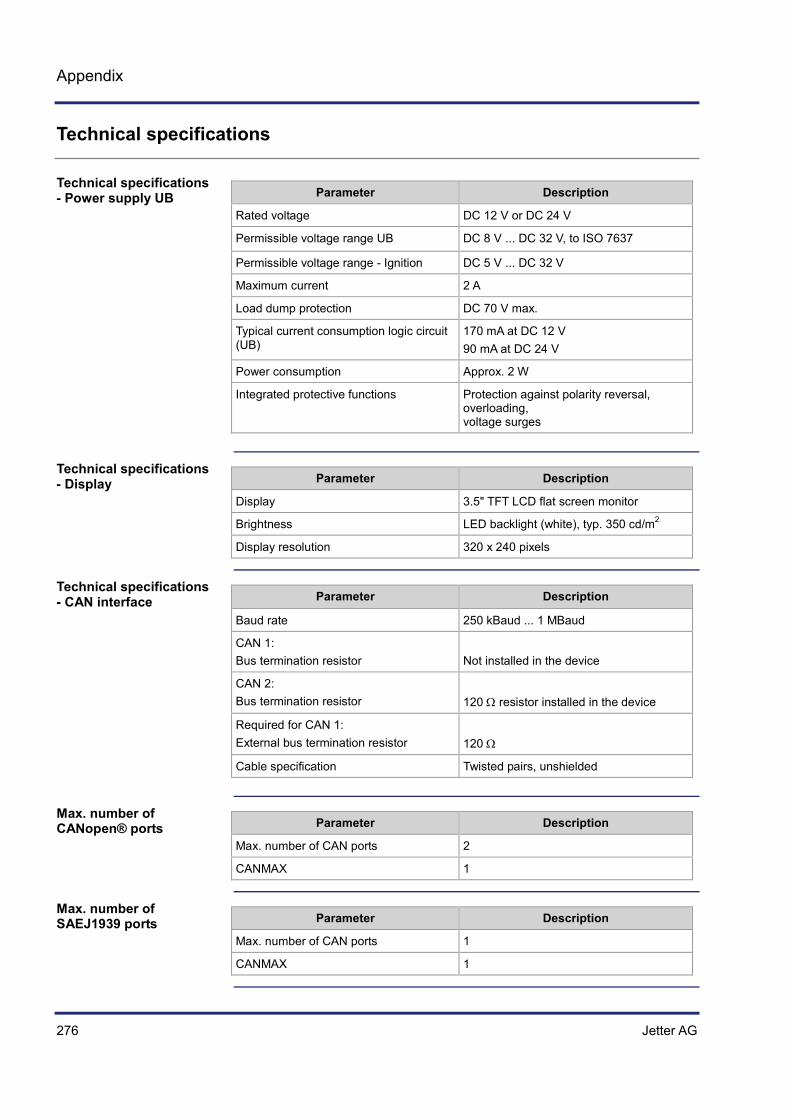
276 Jetter AG
Appendix
Technical specifications
Parameter Description
Rated voltage DC 12 V or DC 24 V
Permissible voltage range UB DC 8 V ... DC 32 V, to ISO 7637
Permissible voltage range - Ignition DC 5 V ... DC 32 V
Maximum current 2 A
Load dump protection DC 70 V max.
Typical current consumption logic circuit (UB)
170 mA at DC 12 V 90 mA at DC 24 V
Power consumption Approx. 2 W
Integrated protective functions Protection against polarity reversal, overloading, voltage surges
Parameter Description
Display 3.5" TFT LCD flat screen monitor
Brightness LED backlight (white), typ. 350 cd/m2
Display resolution 320 x 240 pixels
Parameter Description
Baud rate 250 kBaud ... 1 MBaud
CAN 1: Bus termination resistor
Not installed in the device
CAN 2: Bus termination resistor
120 Ω resistor installed in the device
Required for CAN 1: External bus termination resistor
120 Ω
Cable specification Twisted pairs, unshielded
Parameter Description
Max. number of CAN ports 2
CANMAX 1
Parameter Description
Max. number of CAN ports 1
CANMAX 1
Technical specifications - Power supply UB
Technical specifications - Display
Technical specifications - CAN interface
Max. number of CANopen® ports
Max. number of SAEJ1939 ports

Jetter AG 277
JVM-104 Appendix
Parameter Description
Power supply 5 V, 500 mA max.
USB port USB host interface, USB 2.0
Short-circuit capability Yes Transient short-circuit current: ~ 0.8 A
Parameter Description
Type of terminal RJ45 Ethernet jack
Number of ports 1
Bit rate 10 Mbit/s, 100 Mbit/s
Auto-crossover Yes
Parameter Description
Number of remanent registers 30,000
Remanent memory for variables 120,000 bytes
Flash disk: Total memory Folder App Folder Data
512 MBytes 64 MBytes 368 MBytes
Technical specifications - USB flash drive
Technical specifications - Ethernet
Memory configurations
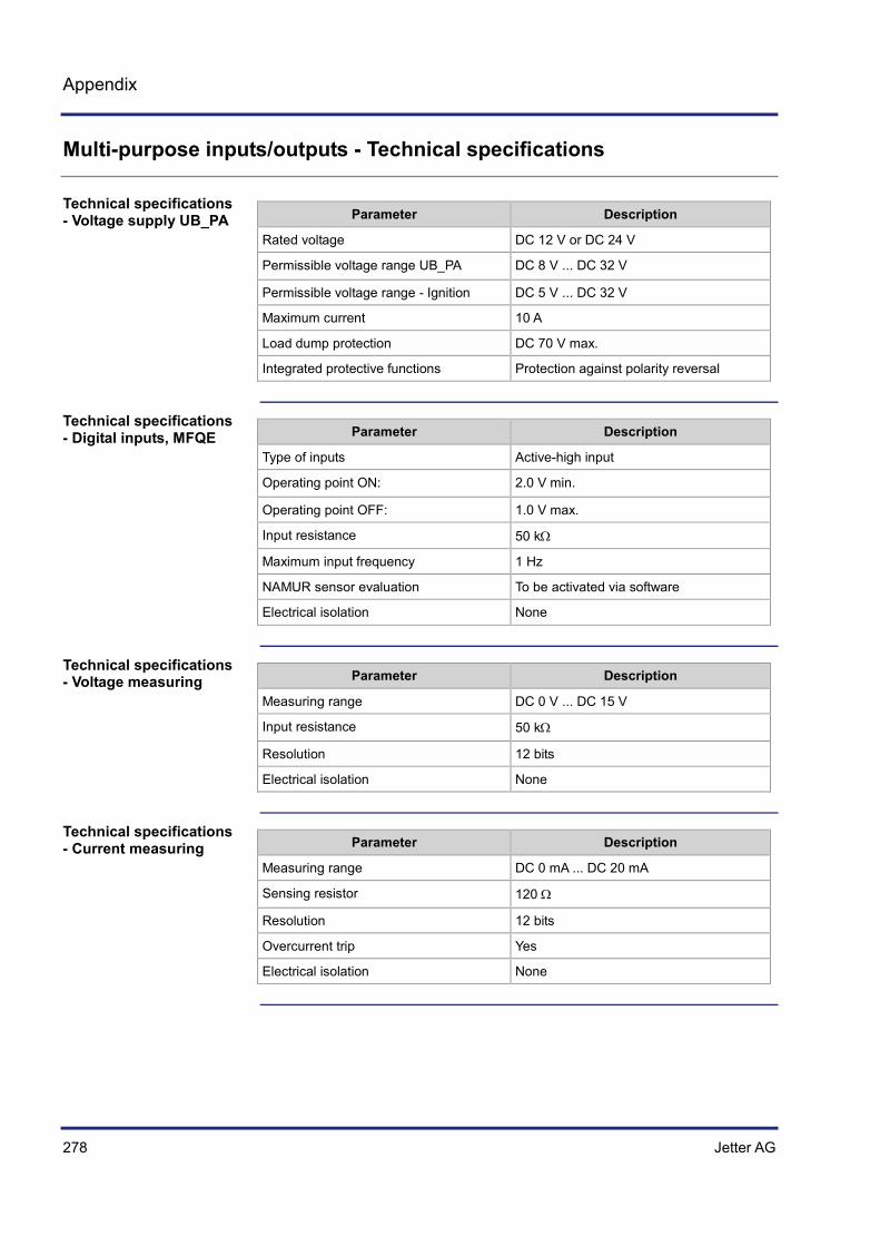
278 Jetter AG
Appendix
Multi-purpose inputs/outputs - Technical specifications
Parameter Description
Rated voltage DC 12 V or DC 24 V
Permissible voltage range UB_PA DC 8 V ... DC 32 V
Permissible voltage range - Ignition DC 5 V ... DC 32 V
Maximum current 10 A
Load dump protection DC 70 V max.
Integrated protective functions Protection against polarity reversal
Parameter Description
Type of inputs Active-high input
Operating point ON: 2.0 V min.
Operating point OFF: 1.0 V max.
Input resistance 50 kΩ
Maximum input frequency 1 Hz
NAMUR sensor evaluation To be activated via software
Electrical isolation None
Parameter Description
Measuring range DC 0 V ... DC 15 V
Input resistance 50 kΩ
Resolution 12 bits
Electrical isolation None
Parameter Description
Measuring range DC 0 mA ... DC 20 mA
Sensing resistor 120 Ω
Resolution 12 bits
Overcurrent trip Yes
Electrical isolation None
Technical specifications - Voltage supply UB_PA
Technical specifications - Digital inputs, MFQE
Technical specifications - Voltage measuring
Technical specifications - Current measuring

Jetter AG 279
JVM-104 Appendix
Parameter Description
Measuring range 0.1 Hz ... 10 kHz
Accuracy 99.9 %
Input resistance 20 kΩ
Typical input current 1 mA max.
Maximum input frequency 10 kHz max.
Period measurement resolution: 1 µs
Adjustable gate times for gate time measuring
1 ms ... 10 s
Duty cycle frequency input 35 µs min.
Operating point ON: 4.7 V min.
Operating point OFF: 2.5 V max.
Parameter Description
Measuring range 0.1 Hz ... 10 kHz
Resolution 0.1 %
Counting range 32 bits
Operating point ON: 4.7 V min.
Operating point OFF: 2.5 V max.
Parameter Description
Type of input Active-high input
Rated voltage UB_PA - 10 %
Operating point ON: DC 1.6 V max., > 3.5 mA
Operating point OFF: DC 4.0 V min., < 0.5 mA
Internal pull-up resistor NAMUR: 1 kΩ, 8.2 V
Electrical isolation None
Technical specifications - Frequency measurement
Technical specifications - Counting function
Technical specifications - Digital input PAx

280 Jetter AG
Appendix
Parameter Description
Maximum output current per channel 2.5 A
Rated voltage Supply voltage UB_PA
Diagnostics Overcurrent, short circuit, cable breakage
Overcurrent evaluation Adjustable currenttrip
Maximum latency: Switching between output and input
500 ms
Maximum total current The total current of all outputs must not exceed 8 A.Otherwise it is cut off after 500 ms. If the total current exceeds 10.5 A, the outputs shut off immediately.
Parameter Description
PWM frequency 100 Hz ... 1 kHz
Resolution of pulse control factor (duty cycle)
0.1 %
Accuracy of pulse control factor (duty cycle)
+/- 42 ns
Maximum rated voltage Supply voltage UB_PA
Switching frequency 100 Hz ... 1kHz
Protective circuitry Overvoltage, overcurrent
Diagnostics Overcurrent, cable breakage
Maximum total current The total current of all outputs must not exceed 8 A. Otherwise it is cut off after 500 ms. If the total current exceeds 10.5 A, the outputs shut off immediately.
Parameter Description
Maximum rated current Battery voltage, DC 32 V max.
Maximum output current 2.5 A
Peak current ~ 5 A, max. 500 ms
Current measuring accuracy +/- 20 %
Switching frequency (1/period length) 100 Hz ... 1 kHz
Frequency accuracy +/- 42 ns
Resolution of pulse control factor (duty cycle)
0.1 %
Diagnostics Overcurrent
Technical specifications - Digital output
Technical specifications - PWM output
Technical specifications - H-bridge

Jetter AG 281
JVM-104 Appendix
Physical dimensions
The illustration below shows the physical dimensions of the JVM-104 in millimeters.
113105
17.6 25 18.73
64.3
128
120
The illustration shows the space required for the HMI JVM-104. It is stated in millimeters.
70
Ensure there is enough space around the housing for servicing requirements.
It should be possible to disconnect the connectors at any time.
Physical dimensions
Space required for installation and service

282 Jetter AG
Appendix
Operating parameters - Environment and mechanics
Parameter Value Standard
Operating temperature range
-20 ... +60 °C
Storage temperature range -20 ... +70 °C ISO 16750-4 DIN EN 60068-2-1 DIN EN 60068-2-2
Air humidity 10 ... 95 % Do not use a steam jet or other such devices to clean the JVM-104.
DIN EN 61131-2
Climate test Humid heat ISO 16750-4
Pollution degree 2 DIN EN 61131-2
Installation location The JVM-104 must be installed in the driver's cab.
Parameter Value Standard
Vibration Broadband noise, 10 Hz/0.005 (m/s2)2/Hz 200 Hz/0.02 (m/s2)2/Hz 300 Hz/0.01 (m/s2)2/Hz 350 Hz/0.002 (m/s2)2/Hz Duration: 3x24 h
To DIN EN 60068-2-64
Shock resistance Sinusoidal half wave, 30 g (300 m/s2), 18 ms, 3 shocks in all 6 orientations
To DIN EN 60068-2-27
Degree of protection Front: IP65 Rear: IP20
DIN EN 60529
Environment
Mechanical parameters

Jetter AG 283
JVM-104 Appendix
Operating parameters - EMC
The voltage testing results comply with DIN EN 16750-2.
Parameter Value Standard
Emitted interference to e1 Frequency band 400 ... 1,000 MHz, limit 63 dB (µV/m), constant
DIN EN 55025
Emitted interference to CE 0.15 ... 0.5 MHz, 66 ... 56 dB (µV) QP DC supply 0.5 ... 5 MHz, 56 dB (µV) QP 5 ... 30 MHz, 60 dB (µV) QP
DIN EN 55011-DC
30 ... 230 MHz, 30/40 dB (µV/m) enclosure 230 ... 1,000 MHz, 37/47 dB (µV/m)
DIN EN 55011-HF
Parameter Value Standard
Immunity to interference to CE
10 V/m over 80 % of the frequency band
DIN EN 61000-4-3
2/1 kV data 4/2 kV power
DIN EN 61000-4-4
± 1 kV line/ground ± 0.5 kV line/line
DIN EN 61000-4-5
10 V, 0.15 ... 80 MHz, 80 % AM sine 1 kHz
DIN EN 61000-4-6
ESD Discharge through air: Test peak voltage 8 kV Contact discharge: Test peak voltage 4 kV
DIN EN 61000-4-2
Voltage testing at UB and UB_PA
EMC - Emitted interference
EMC - Immunity to interference
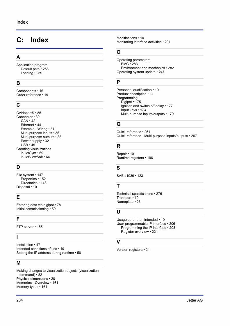
284 Jetter AG
Index
C: Index
A Application program
Default path • 258 Loading • 259
B Components • 16 Order reference • 19
C CANopen® • 85 Connector • 30
CAN • 42 Ethernet • 44 Example - Wiring • 31 Multi-purpose inputs • 35 Multi-purpose outputs • 38 Power supply • 32 USB • 45
Creating visualizations in JetSym • 69 in JetViewSoft • 64
D File system • 147
Properties • 152 Directories • 148
Disposal • 10
E Entering data via digipot • 78 Initial commissioning • 59
F FTP server • 155
I Installation • 47 Intended conditions of use • 10 Setting the IP address during runtime • 56
M Making changes to visualization objects (visualization
command) • 82 Physical dimensions • 20 Memories - Overview • 161 Memory types • 161
Modifications • 10 Monitoring interface activities • 201
O Operating parameters
EMC • 283 Environment and mechanics • 282
Operating system update • 247
P Personnel qualification • 10 Product description • 14 Programming
Digipot • 175 Ignition and switch off delay • 177 Input keys • 173 Multi-purpose inputs/outputs • 179
Q Quick reference • 261 Quick reference - Multi-purpose inputs/outputs • 267
R Repair • 10 Runtime registers • 196
S SAE J1939 • 123
T Technical specifications • 276 Transport • 10 Nameplate • 23
U Usage other than intended • 10 User-programmable IP interface • 206
Programming the IP interface • 208 Register overview • 221
V Version registers • 24


Jetter AG Graeterstrasse 2 71642 Ludwigsburg | Germany Phone +49 7141 2550-0 Fax +49 7141 2550-425 [email protected] www.jetter.de
We automate your success.