Embed Size (px)
Citation preview
KRAMER ELECTRONICS LTD.
USER MANUAL
MODEL:
SL-1N Master Room Controller
P/N: 2900-300399 Rev 3
SL-1N – Contents i
Contents
1 Introduction 1 2 Getting Started 2 2.1 Achieving the Best Performance 2 2.2 Safety Instructions 3 2.3 Recycling Kramer Products 3 3 Overview 4 3.1 Defining the SL-1N Master Room Controller 5 4 Connecting the SL-1N 7 4.1 Connecting the RS-232 Port 8 4.2 Connecting the Ethernet Port 9 4.3 Connecting the K-NET Port 9 5 Operating the SL-1N 10 6 Technical Specifications 11
Figures
Figure 1: SL-1N Master Room Controller 5 Figure 2: Connecting the SL-1N Master Room Controller 8 Figure 3: RS-232 Connection 8 Figure 4: K-NET Pinout Connection 9
SL-1N - Introduction 1
1 Introduction
Welcome to Kramer Electronics! Since 1981, Kramer Electronics has been
providing a world of unique, creative, and affordable solutions to the vast range of
problems that confront video, audio, presentation, and broadcasting professionals
on a daily basis. In recent years, we have redesigned and upgraded most of our
line, making the best even better!
Our 1,000-plus different models now appear in 14 groups that are clearly defined
by function: GROUP 1: Distribution Amplifiers; GROUP 2: Switchers and Routers;
GROUP 3: Control Systems; GROUP 4: Format/Standards Converters; GROUP 5:
Range Extenders and Repeaters; GROUP 6: Specialty AV Products; GROUP 7:
Scan Converters and Scalers; GROUP 8: Cables and Connectors; GROUP 9:
Room Connectivity; GROUP 10: Accessories and Rack Adapters; GROUP 11:
Sierra Video Products; GROUP 12: Digital Signage; GROUP 13: Audio; and
GROUP 14: Collaboration.
Congratulations on purchasing your Kramer SL-1N Master Room Controller, which
is ideal for the following typical applications:
• Master room controller for room control systems
• Multimedia room control, such as classrooms and meeting rooms
2 SL-1N - Getting Started
2 Getting Started
We recommend that you:
• Unpack the equipment carefully and save the original box and packaging materials for possible future shipment
• Review the contents of this user manual
Go to www.kramerav.com/support/product_downloads.asp to check for up-to-date user manuals, application programs, and to check if firmware upgrades are available (where appropriate).
2.1 Achieving the Best Performance
To achieve the best performance:
• Use only good quality connection cables (we recommend Kramer high-performance, high-resolution cables) to avoid interference, deterioration in signal quality due to poor matching, and elevated noise levels (often associated with low quality cables)
• Do not secure the cables in tight bundles or roll the slack into tight coils
• Avoid interference from neighboring electrical appliances that may adversely influence signal quality
• Position your Kramer SL-1N away from moisture, excessive sunlight and dust
This equipment is to be used only inside a building. It may only be connected to other equipment that is installed inside a building.
i
!
SL-1N - Getting Started 3
2.2 Safety Instructions
Caution: There are no operator serviceable parts inside the unit
Warning: Use only the Kramer Electronics input power wall adapter that is provided with the unit
Warning: Disconnect the power and unplug the unit from the wall before installing
2.3 Recycling Kramer Products
The Waste Electrical and Electronic Equipment (WEEE) Directive 2002/96/EC
aims to reduce the amount of WEEE sent for disposal to landfill or incineration by
requiring it to be collected and recycled. To comply with the WEEE Directive,
Kramer Electronics has made arrangements with the European Advanced
Recycling Network (EARN) and will cover any costs of treatment, recycling and
recovery of waste Kramer Electronics branded equipment on arrival at the EARN
facility. For details of Kramer’s recycling arrangements in your particular country
go to our recycling pages at www.kramerav.com/support/recycling/.
!
4 SL-1N - Overview
3 Overview
The SL-1N is a highly versatile controller; an all-in-one extended remote control
panel for control of AV equipment—especially projectors and associated
equipment—in any room (such as classrooms, boardrooms, or auditoriums). It
streamlines operations and simplifies control by integrating audio, video, and
computer-video sources into a centralized system.
The SL-1N features:
• 2 bidirectional RS-232 ports to control AV equipment such as projectors, LCD and PDP displays, power amplifiers, switchers and scalers
• 3 relay contact closure ports to control other room items related to the AV system such as raising and lowering drapes, the screen or the projector
• IR control - 1 input (3.5mm) and 2 outputs (terminals blocks)
• IR Learning that learns commands from any IR remote
• Compatibility with Kramer Site-CTRL™ software for network remote control and management over the Ethernet port
• A K-NET™ control channel for connecting compatible user interfaces and supplying power and control data over a single cable
• A USB port for loading device firmware
• Flexible control using Ethernet, K-NET™, IR sensors and external IR commands.
SL-1N - Overview 5
3.1 Defining the SL-1N Master Room Controller
This section defines the SL-1N.
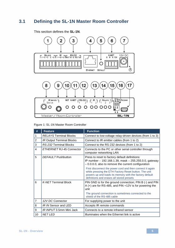
Figure 1: SL-1N Master Room Controller
# Feature Function 1 RELAYS Terminal Blocks Connect to low-voltage relay-driven devices (from 1 to 3) 2 IR Output Terminal Blocks Connect to IR emitter cables (from 1 to 2) 3 RS-232 Terminal Blocks Connect to the RS-232 devices (from 1 to 2) 4 ETHERNET RJ-45 Connector Connects to the PC or other serial controller through
computer networking LAN 5 DEFAULT Pushbutton Press to reset to factory default definitions:
IP number − 192.168.1.39, mask – 255.255.0.0, gateway – 0.0.0.0, also to remove the current configuration First disconnect the power cord and then connect it again while pressing the ETH Factory Reset button. The unit powers up and loads its memory with the factory default definitions and erases all stored presets
6 K-NET Terminal Block PIN GND is for the ground connection; PIN B (-) and PIN A (+) are for RS-485, and PIN +12V is for powering the unit The ground connection is sometimes connected to the shield of the RS-485 cable
7 12V DC Connector For supplying power to the unit 8 IR IN Sensor and LED Accepts IR remote commands 9 IR INPUT 3.5mm Mini Jack Connects to a remote infrared sensor 10 NET LED Illuminates when the Ethernet link is active
6 SL-1N - Overview
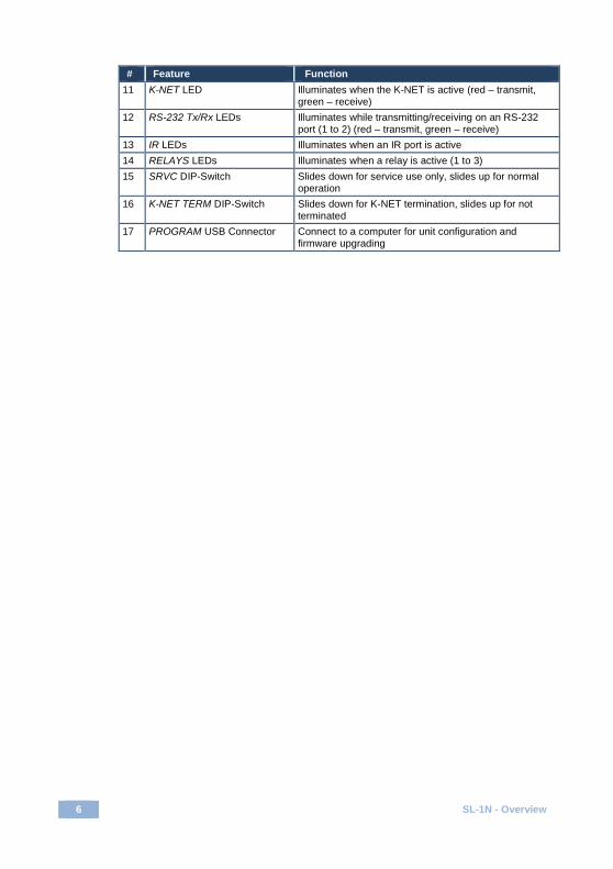
# Feature Function 11 K-NET LED Illuminates when the K-NET is active (red – transmit,
green – receive) 12 RS-232 Tx/Rx LEDs Illuminates while transmitting/receiving on an RS-232
port (1 to 2) (red – transmit, green – receive) 13 IR LEDs Illuminates when an IR port is active 14 RELAYS LEDs Illuminates when a relay is active (1 to 3) 15 SRVC DIP-Switch Slides down for service use only, slides up for normal
operation 16 K-NET TERM DIP-Switch Slides down for K-NET termination, slides up for not
terminated 17 PROGRAM USB Connector Connect to a computer for unit configuration and
firmware upgrading
SL-1N - Connecting the SL-1N 7
4 Connecting the SL-1N
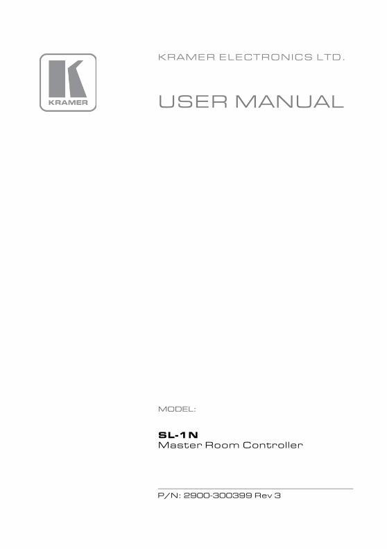
Always switch off the power to each device before connecting it to your SL-1N. After connecting your SL-1N, connect its power and then switch on the power to each device.
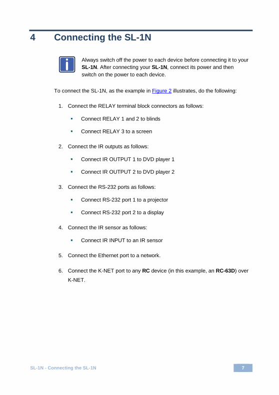
To connect the SL-1N, as the example in Figure 2 illustrates, do the following:
1. Connect the RELAY terminal block connectors as follows:
Connect RELAY 1 and 2 to blinds
Connect RELAY 3 to a screen
2. Connect the IR outputs as follows:
Connect IR OUTPUT 1 to DVD player 1
Connect IR OUTPUT 2 to DVD player 2
3. Connect the RS-232 ports as follows:
Connect RS-232 port 1 to a projector
Connect RS-232 port 2 to a display
4. Connect the IR sensor as follows:
Connect IR INPUT to an IR sensor
5. Connect the Ethernet port to a network.
6. Connect the K-NET port to any RC device (in this example, an RC-63D) over
K-NET.
i

8 SL-1N - Connecting the SL-1N
Figure 2: Connecting the SL-1N Master Room Controller
4.1 Connecting the RS-232 Port
To connect an AV device to the SL-1NN, connect the RS-232 9-pin D-sub port on
your device to the RS-232 terminal block on the rear panel of the SL-1N controller
as shown in Figure 3:
Figure 3: RS-232 Connection
SL-1N - Connecting the SL-1N 9
4.2 Connecting the Ethernet Port
The Ethernet connection of the SL-1N allows you to perform all control functions of
the SL-1N over the Internet using a PC running the Kramer Site-CTRL control
program.
To connect the SL-1N to a network:
1. Connect the Ethernet port of the SL-1N to the Ethernet port on a network
hub or network router, via a straight cable with RJ-45 connectors.
2. At the other end, connect a PC running Site-CTRL to the network.
After connecting the Ethernet port, you have to install and configure it. For detailed
instructions on how to install and configure your Ethernet port, see the K-Config
Configuration Guide available for download at the Kramer Web site:
www.kramerav.com.
4.3 Connecting the K-NET Port
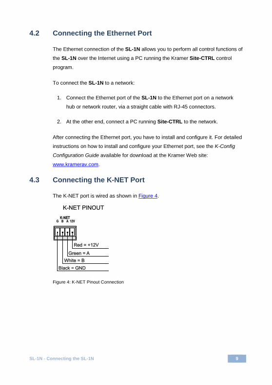
The K-NET port is wired as shown in Figure 4.
Figure 4: K-NET Pinout Connection
10 SL-1N - Operating the SL-1N
5 Operating the SL-1N
You can operate your SL-1N using:
• A K-NET-compatible remote controller or auxiliary control panel: To operate your device using an external K-Net device, see the K-Config Configuration Guide
• The optional RC-4 Infrared remote control transmitter: To operate your device using the infrared remote controller, see the User Manual packed with the remote controller
• A PC running Site-CTRL control software: To operate your device using Site-CTRL, see the Site-CTRL and Web Access Online User Guide
SL-1N - Technical Specifications 11
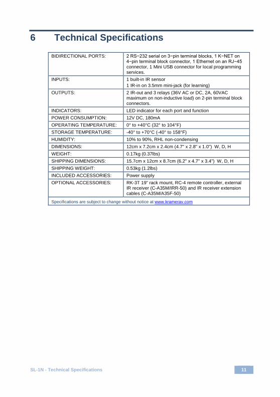
6 Technical Specifications
BIDIRECTIONAL PORTS: 2 RS−232 serial on 3−pin terminal blocks, 1 K−NET on 4−pin terminal block connector, 1 Ethernet on an RJ−45 connector, 1 Mini USB connector for local programming services.
INPUTS: 1 built-in IR sensor 1 IR-in on 3.5mm mini-jack (for learning)
OUTPUTS: 2 IR-out and 3 relays (36V AC or DC, 2A, 60VAC maximum on non-inductive load) on 2-pin terminal block connectors.
INDICATORS: LED indicator for each port and function POWER CONSUMPTION: 12V DC, 180mA OPERATING TEMPERATURE: 0° to +40°C (32° to 104°F) STORAGE TEMPERATURE: -40° to +70°C (-40° to 158°F) HUMIDITY: 10% to 90%, RHL non-condensing DIMENSIONS: 12cm x 7.2cm x 2.4cm (4.7" x 2.8" x 1.0") W, D, H WEIGHT: 0.17kg (0.37lbs) SHIPPING DIMENSIONS: 15.7cm x 12cm x 8.7cm (6.2" x 4.7" x 3.4") W, D, H SHIPPING WEIGHT: 0.53kg (1.2lbs) INCLUDED ACCESSORIES: Power supply OPTIONAL ACCESSORIES: RK-3T 19” rack mount, RC-4 remote controller, external
IR receiver (C-A35M/IRR-50) and IR receiver extension cables (C-A35M/A35F-50)
Specifications are subject to change without notice at www.kramerav.com
For the latest information on our products and a list of Kramer distributors, visit our Web site where updates to this user manual may be found.
We welcome your questions, comments, and feedback. Web site: www.kramerav.com E-mail: [email protected]
SAFETY WARNINGDisconnect the unit from the powersupply before opening and servicing
P/N: 2900-300399 Rev: 3
!


![REMOTE CONTROLLER (WIRED TYPE) - Планета Климата · REMOTE CONTROLLER (WIRED TYPE) [Original instructions] OPERATING MANUAL WIRED REMOTE CONTROLLER Keep this manual](https://img.pdfslide.net/doc/110x75/5c9f331488c993502d8ceaa7/remote-controller-wired-type-remote-controller.jpg)