Embed Size (px)
Citation preview
1
USER MANUAL
Ledshow YQ
Version:V1.0 Date:2020.4.30
2
DIRECTORY
Instruction.................................................................................................................................................................. 6
Description.........................................................................................................................................................6
Operation system.............................................................................................................................................6
Install and uninstall......................................................................................................................................... 7
Menu interface................................................................................................................................................11
Menu and tools.............................................................................................................................................. 12
Basic setting.............................................................................................................................................................21
Connect the device........................................................................................................................................21
Add screen....................................................................................................................................................... 22
Controller IP configuration......................................................................................................................... 27
Set screen parameters.................................................................................................................................. 29
WIFI Configuration........................................................................................................................................ 32
Scan configuration........................................................................................................................................ 37
Connection configuration........................................................................................................................... 49
Server configuration............................................................................................................................................. 55
Setup server IP information........................................................................................................................55
Controller connect to the wireless router...............................................................................................61
WEB server communication........................................................................................................................65
ADD PROGRAM STEPS......................................................................................................................................... 72
3
Add program...................................................................................................................................................72
Add picture zone............................................................................................................................................74
Finish program edit....................................................................................................................................... 75
Play program...................................................................................................................................................75
AREA EDIT USER MANUAL..................................................................................................................................75
Add notification..............................................................................................................................................75
Play video......................................................................................................................................................... 77
Play subtitle..................................................................................................................................................... 80
TIME................................................................................................................................................................... 82
Weather zone..................................................................................................................................................83
Database...........................................................................................................................................................84
Sensor display.................................................................................................................................................90
Colorful words................................................................................................................................................ 93
Dynamic display............................................................................................................................................. 96
Firmware maintenance................................................................................................................................. 97
Common functions..............................................................................................................................................101
Time correction............................................................................................................................................ 101
Brightness...................................................................................................................................................... 101
Volume............................................................................................................................................................ 104
Advanced................................................................................................................................................................105
Log management.........................................................................................................................................105
Advanced........................................................................................................................................................106
Switch storage media................................................................................................................................. 107
Logo configuration......................................................................................................................................107
Display LED screen debug.........................................................................................................................108
Set IP display flag.........................................................................................................................................109

4
IO configuration........................................................................................................................................... 109
Set output type.............................................................................................................................................109
Setup working mode.................................................................................................................................. 110
multi-screen synchronization function.................................................................................................. 111
Set network time..........................................................................................................................................112
Set access APN............................................................................................................................................. 113
Font manage................................................................................................................................................. 113
Switch language........................................................................................................................................... 114
Screen monitor............................................................................................................................................. 115
JTC special configuration...........................................................................................................................116
User management....................................................................................................................................... 116
Delete user..................................................................................................................................................... 118
Modify the password.................................................................................................................................. 118
Certification user..........................................................................................................................................118
Quick turning screen...................................................................................................................................118
Certificate management............................................................................................................................ 119
Group function..................................................................................................................................................... 120
Sending program.........................................................................................................................................120
Reset screen parameters............................................................................................................................121
Volume............................................................................................................................................................ 122
Brightness...................................................................................................................................................... 123
Correction time.............................................................................................................................................125
Turn on............................................................................................................................................................ 126
Turn off............................................................................................................................................................127
Time for switch............................................................................................................................................. 128
Query firmware.............................................................................................................................................129

5
Firmware update.......................................................................................................................................... 130
6
Instruction
Thank you for purchasing our LED multimedia player. hope you can
enjoy the excellent performance of this product. The design of the LED
multimedia player meets international and industry standards, but if
improperly operated, it may still cause personal injury and property
damage. Avoid possible dangers caused by the equipment and avoid
entering from your equipment. When installing and operating the
product, please follow the relevant instructions in this manual.
Description
LedshowYQ 2018 software support graphic editing software dedicatedto YQ series asynchronous full-color controllers. It is powerful, simpleand practical. At present, there are partitions such as video area, graphicarea, subtitle area, time area, dial area, lunar area, table area, databasearea, and sensor area. It supports dynamic preview of partitions, which isconvenient for users to edit programs more intuitively and efficiently.The software supports the display parameter configuration andscanning configuration of the new generation of high-brush architectureproducts, and the network port output can be customized. The productsupports the adjustment of brightness, volume, switch on and off,supports direct connection of a single machine, fixed IP, server, USBcommunication mode, WIFI mode..
Operation system
LedshowYQ 2018 support Windows XP、Vista、Windows 7、Windows
8、Windows10.
7
Install and uninstall
1. Software install
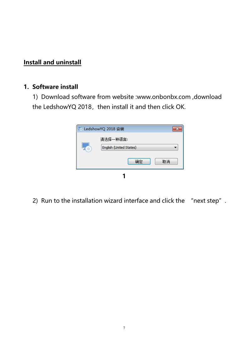
1) Download software from website :www.onbonbx.com ,download
the LedshowYQ 2018,then install it and then click OK.
1
2) Run to the installation wizard interface and click the “next step”.

8
2
3
9
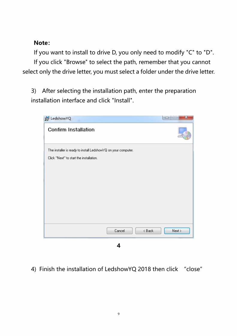
Note:
If you want to install to drive D, you only need to modify "C" to "D".
If you click "Browse" to select the path, remember that you cannot
select only the drive letter, you must select a folder under the drive letter.
3) After selecting the installation path, enter the preparation
installation interface and click "Install".
4
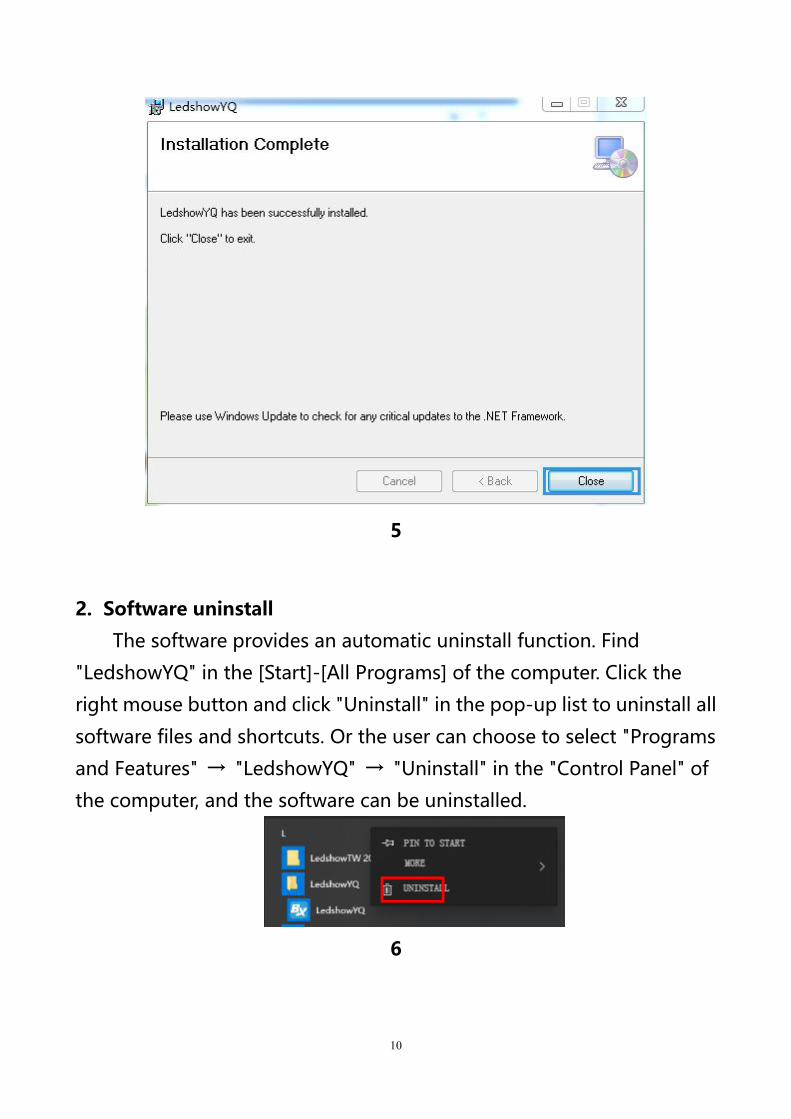
4) Finish the installation of LedshowYQ 2018 then click “close”
10
5
2. Software uninstall
The software provides an automatic uninstall function. Find
"LedshowYQ" in the [Start]-[All Programs] of the computer. Click the
right mouse button and click "Uninstall" in the pop-up list to uninstall all
software files and shortcuts. Or the user can choose to select "Programs
and Features" → "LedshowYQ" → "Uninstall" in the "Control Panel" of
the computer, and the software can be uninstalled.
6
11
Menu interface
7
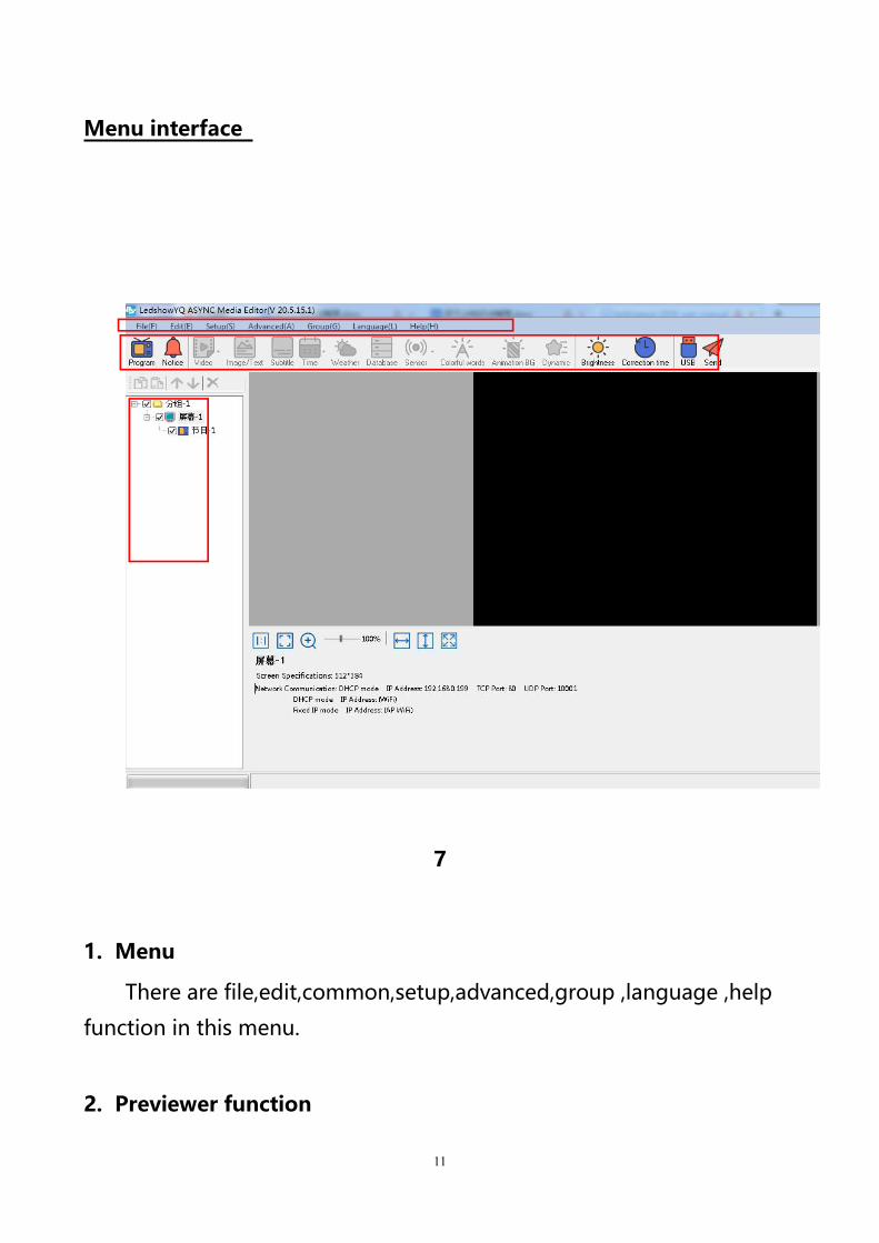
1. Menu
There are file,edit,common,setup,advanced,group ,language ,help
function in this menu.
2. Previewer function
12
Preview area is the LED screen preview window on the computer.
3. Edit window
Edit window mainly for edit program parameters ,set program
name,X value ,Y value ,width ,height,display effect ,run speed ,stay time
and so on .
4. Program area
Program is for edit different text&image area ,subtitle area ,video
area ,weather etc.
5. Major menu
User can add new
program ,text ,subtitle ,time ,video ,weather ,sensor etc.
Menu and tools
1. Major menu
8
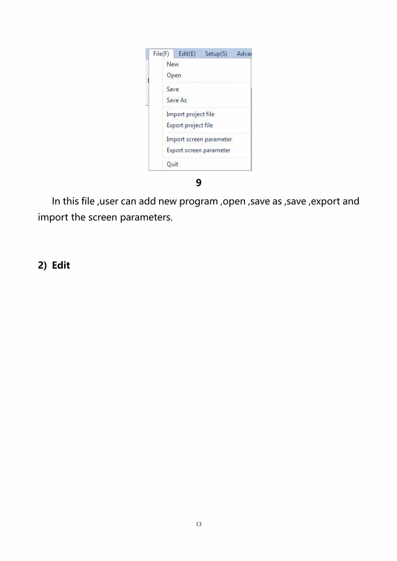
1) File
13
9
In this file ,user can add new program ,open ,save as ,save ,export and
import the screen parameters.
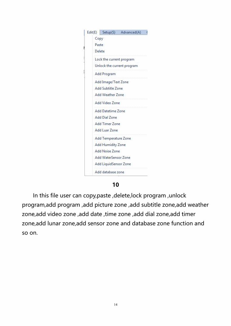
2) Edit
14
10
In this file user can copy,paste ,delete,lock program ,unlock
program,add program ,add picture zone ,add subtitle zone,add weather
zone,add video zone ,add date ,time zone ,add dial zone,add timer
zone,add lunar zone,add sensor zone and database zone function and
so on.
15
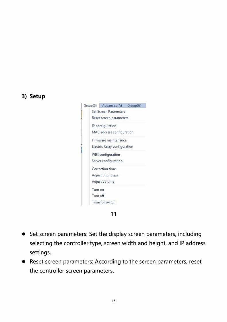
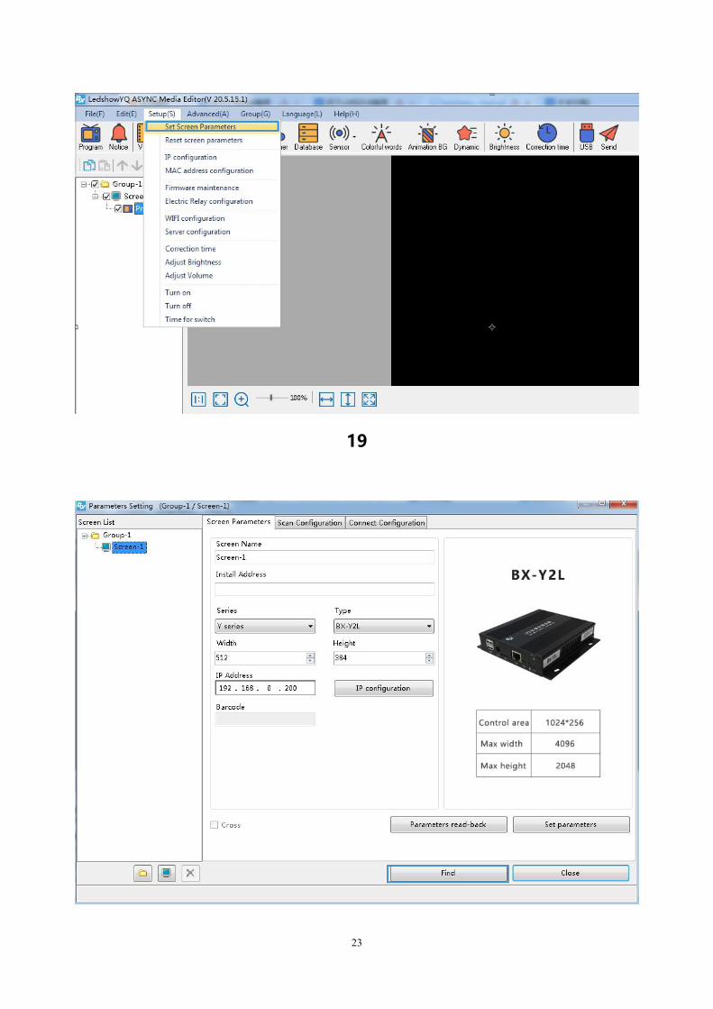
3) Setup
11
Set screen parameters: Set the display screen parameters, including
selecting the controller type, screen width and height, and IP address
settings.
Reset screen parameters: According to the screen parameters, reset
the controller screen parameters.
16
Controller IP setting: Set the parameters such as the IP address of the
online controller, or set the parameters of the IP address of the
controller with only one LAN.
MAC configuration: After setting IP to stand-alone configuration, set
the MAC address. Controller firmware maintenance: upgrade the
controller program, FPGA program, receiving card program or
multi-function card program.
Relay configuration: you can directly connect the relay or connect the
relay through the VMF multi-function card to implement the relay
after related configuration control function.
WIFI configuration: it is divided into STA mode and AP mode, STA
mode is the setting that the controller connects to the external WIFI
network, and AP mode is the controller used as a hotspot to connect
the computer to the controller WIFI.
Server Settings: Set the server port, turn on and off the server.
Time calibration: complete the time calibration with the time chip in
the controller. Brightness: Set the brightness of the screen.
Volume: You can adjust the volume of external audio or video
equipment.
Turn on: turn on the screen. Shutdown: Turn off the screen.
Timing switch: you can set the time of turning on and off by yourself.
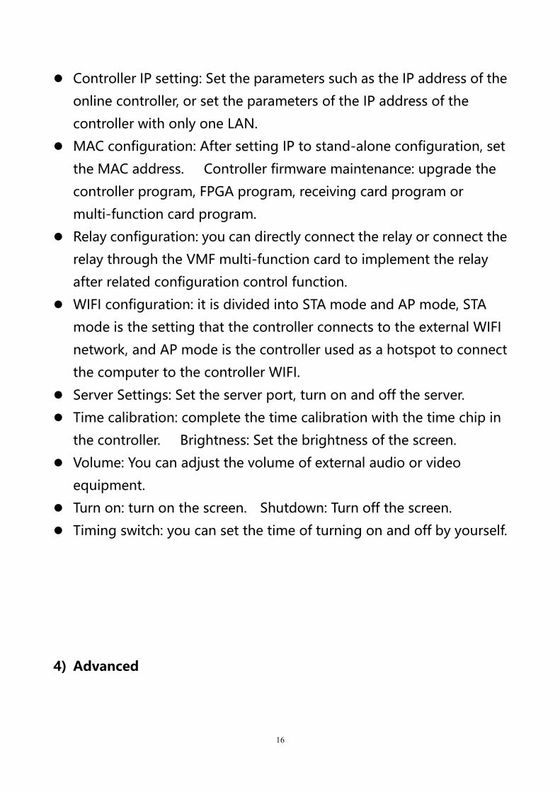
4) Advanced
17
12
Advanced menus include: log management, status query, switching
storage media, logo configuration, LED tag configuration, IP tag
configuration, pin configuration, setting output mode, setting working
mode, multi-screen simultaneous display, setting network timing,
setting access point (APN), font management, switching languages,
screen monitoring, JTC special configuration, password modification,
user management, cloud backup, quick screen adjustment and
certificate management and other operations.
18
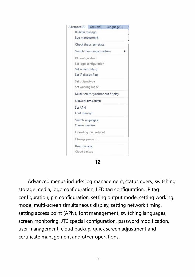
5) Group
13
The group menu includes: send programs, reset screen parameters,
controller IP configuration, volume, brightness, time adjustment, power
on, power off, timer switch, query controller program controller firmware
maintenance and other functions. Users can use these functions to
achieve Multiple LED screens under different groups perform group
operations.
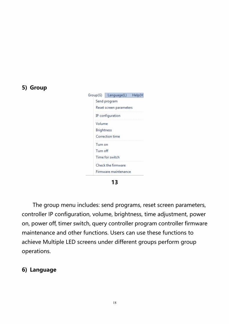
6) Language
19
14
After the software is installed, you can change the display language.
Support Simplified Chinese, Traditional Chinese, English, Korean,
Japanese, French, Russian, Thai, Arabic, German, Spanish, Portuguese,
Vietnamese, Kazakh, Croatian, Turkish, a total of 16 languages.
7) Help
Click”about”to check the software version.
20
15
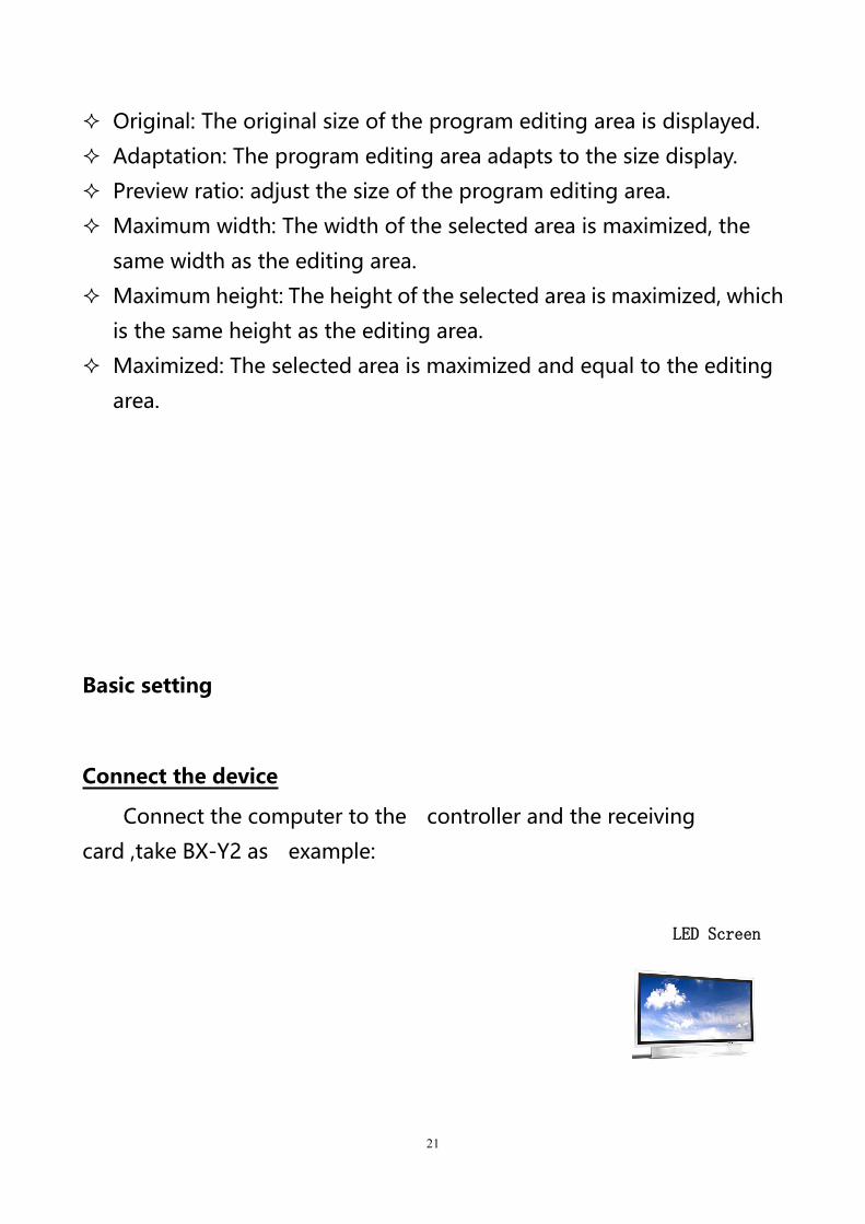
2. Major tools
By selecting the buttons on the main toolbar, users can directly
create new programs, add notifications, create new videos, graphics,
subtitles, time, weather, databases, sensors, colorful words, colorful
backgrounds, dynamic areas, etc., as well as adjust brightness, School
time, USB download and send programs and other operations.
16
3. Window toolbar
17
21
Original: The original size of the program editing area is displayed.
Adaptation: The program editing area adapts to the size display.
Preview ratio: adjust the size of the program editing area.
Maximum width: The width of the selected area is maximized, the
same width as the editing area.
Maximum height: The height of the selected area is maximized, which
is the same height as the editing area.
Maximized: The selected area is maximized and equal to the editing
area.
Basic setting
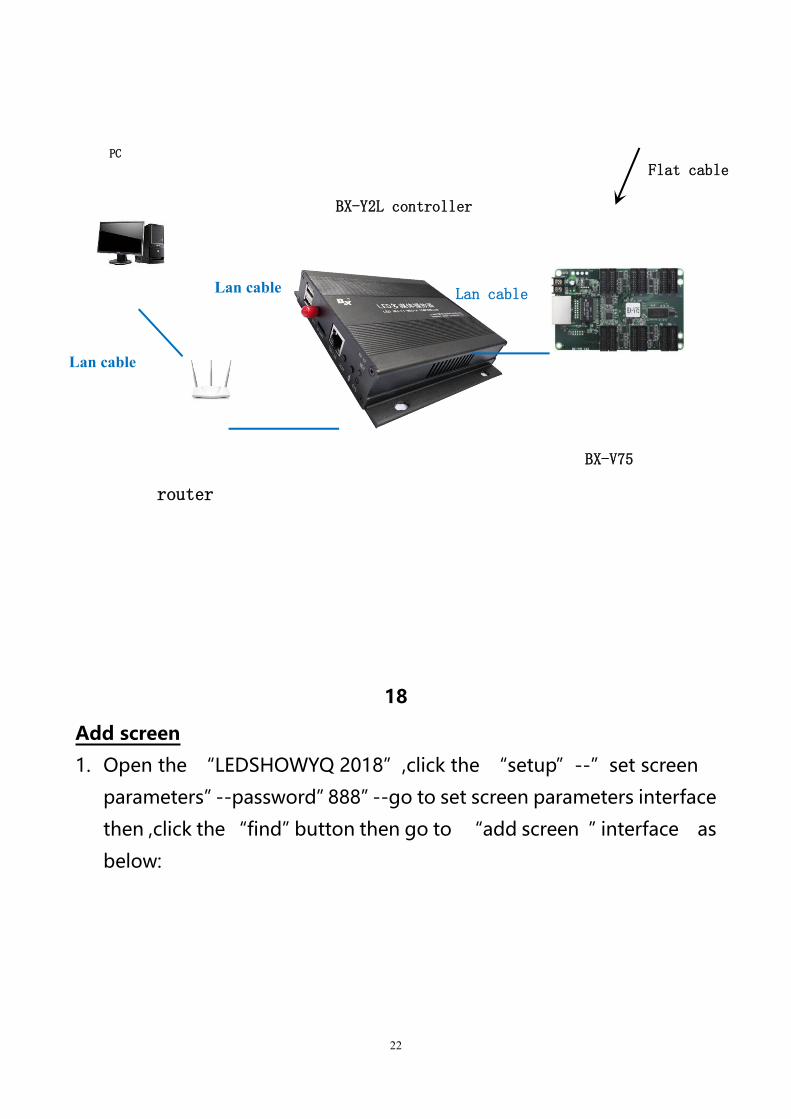
Connect the device
Connect the computer to the controller and the receiving
card ,take BX-Y2 as example:
LED Screen
22
18
Add screen
1. Open the “LEDSHOWYQ 2018”,click the “setup”--”set screen
parameters”--password”888”--go to set screen parameters interface
then ,click the “find”button then go to “add screen ”interface as
below:
Flat cable
Lan cable
Lan cable
Lan cable
PC
router
BX-Y2L controller
BX-V75
23
19
24
20
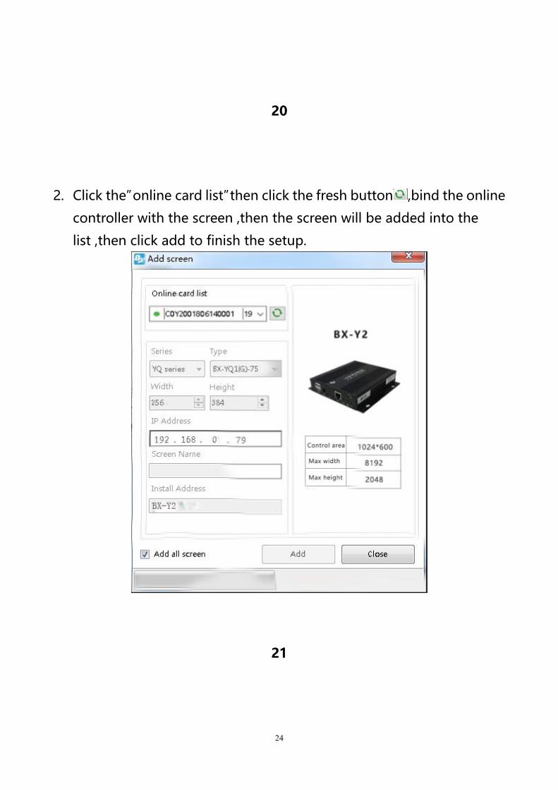
2. Click the”online card list”then click the fresh button ,bind the online
controller with the screen ,then the screen will be added into the
list ,then click add to finish the setup.
21
25
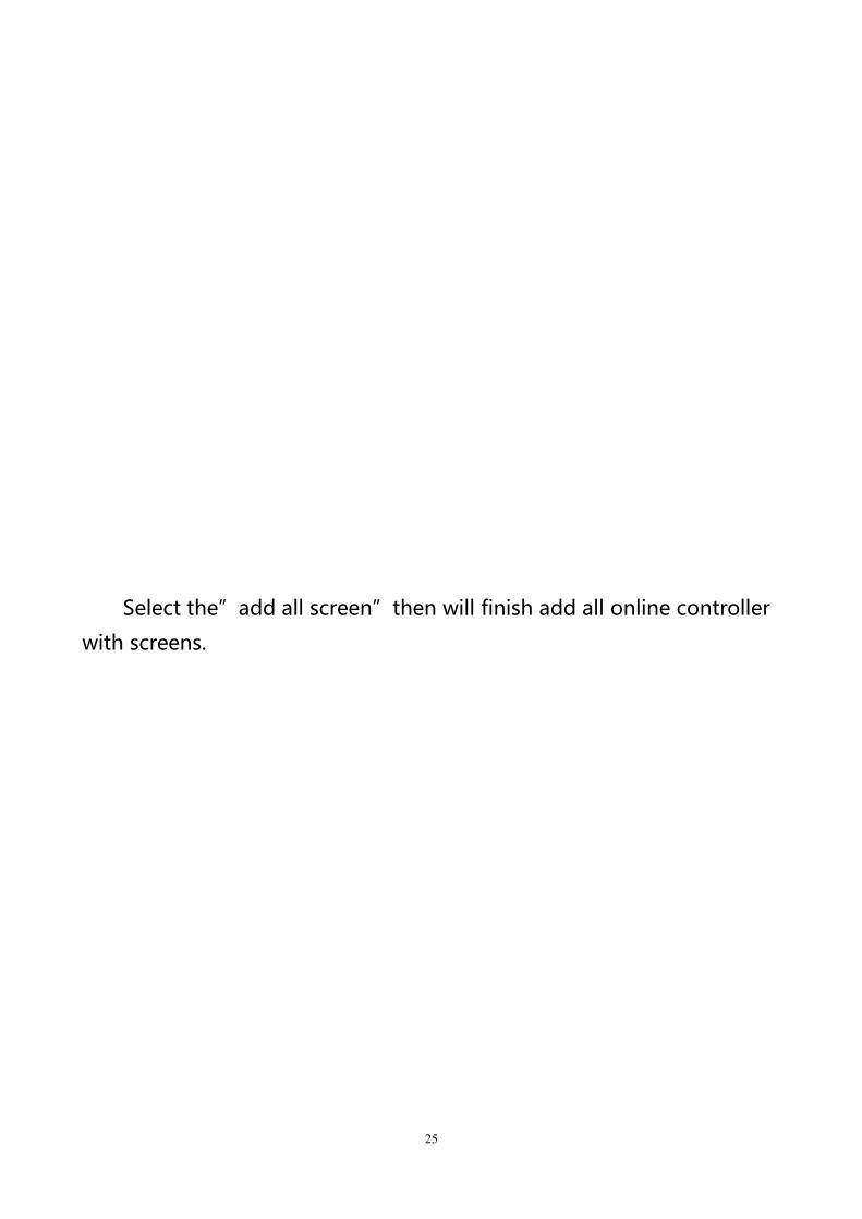
Select the”add all screen”then will finish add all online controller
with screens.
26
22
27
23
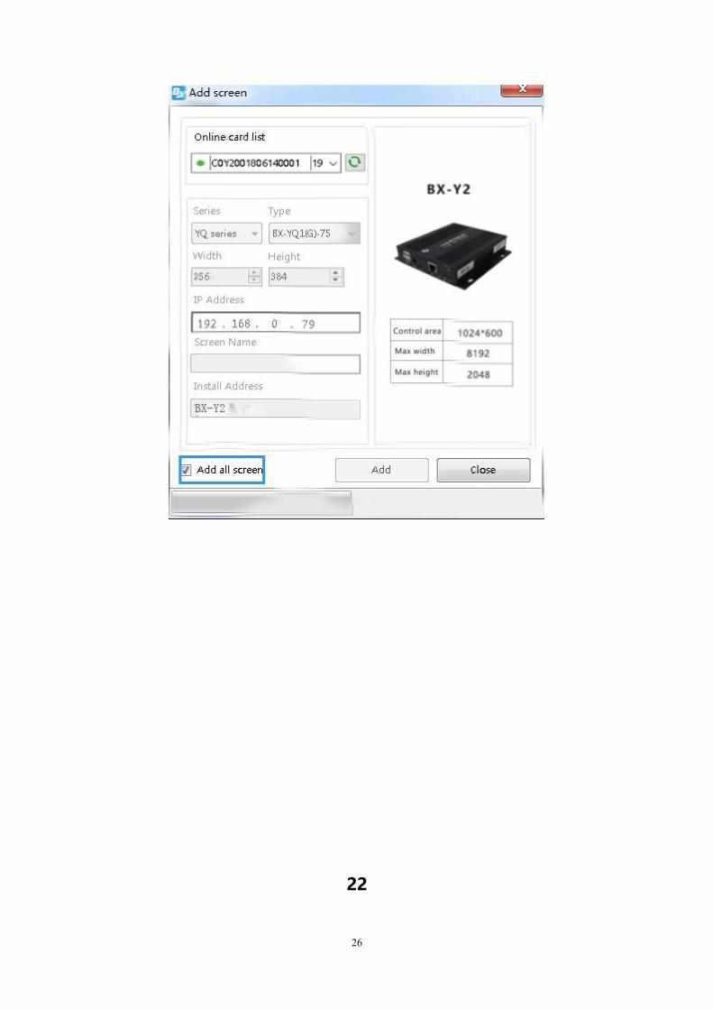
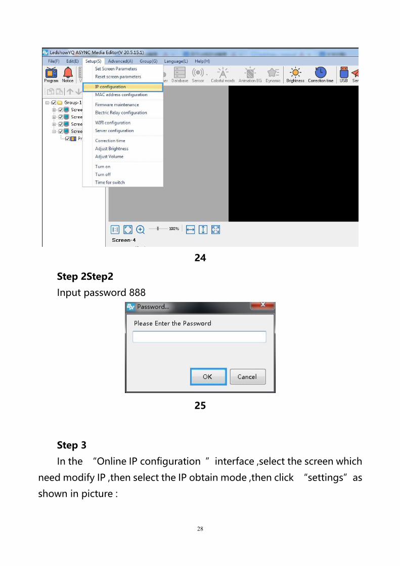
Controller IP configuration
Step 1Step 2
Click the “setup”--”IP configuration”as below
28
24
Step 2Step2
Input password 888
25
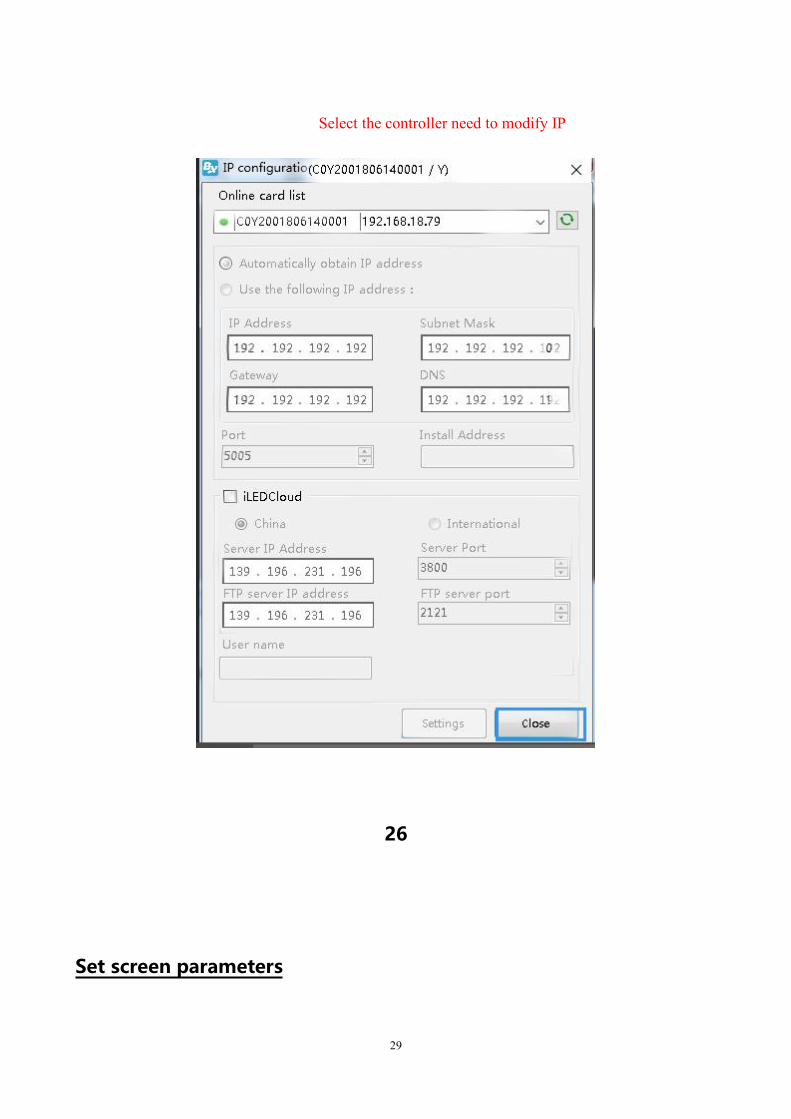
Step 3
In the “Online IP configuration ”interface ,select the screen which
need modify IP ,then select the IP obtain mode ,then click “settings”as
shown in picture :
29
26
Set screen parameters
Select the controller need to modify IP
30
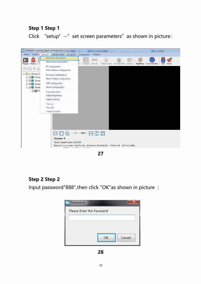
Step 1 Step 1
Click “setup”--”set screen parameters”as shown in picture:
27
Step 2 Step 2
Input password"888",then click "OK"as shown in picture :
28
31
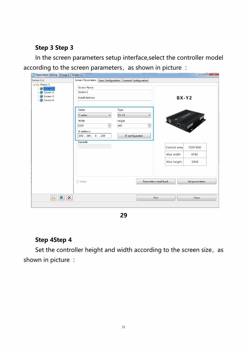
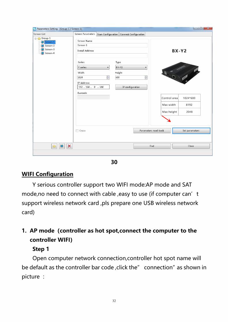
Step 3 Step 3
In the screen parameters setup interface,select the controller model
according to the screen parameters,as shown in picture :
29
Step 4Step 4
Set the controller height and width according to the screen size,as
shown in picture :
32
30
WIFI Configuration
Y serious controller support two WIFI mode:AP mode and SAT
mode,no need to connect with cable ,easy to use (if computer can’t
support wireless network card ,pls prepare one USB wireless network
card)
1. AP mode(controller as hot spot,connect the computer to the
controller WIFI)
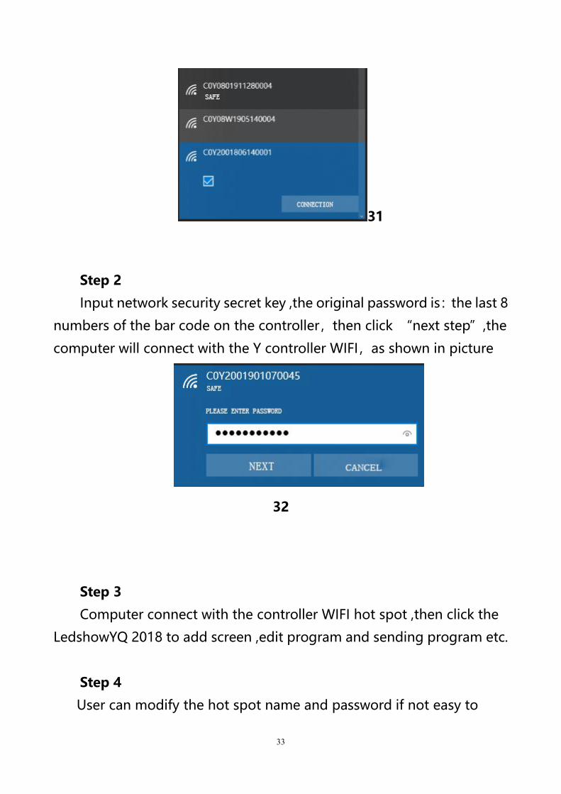
Step 1
Open computer network connection,controller hot spot name will
be default as the controller bar code ,click the” connection”as shown in
picture :
33
31
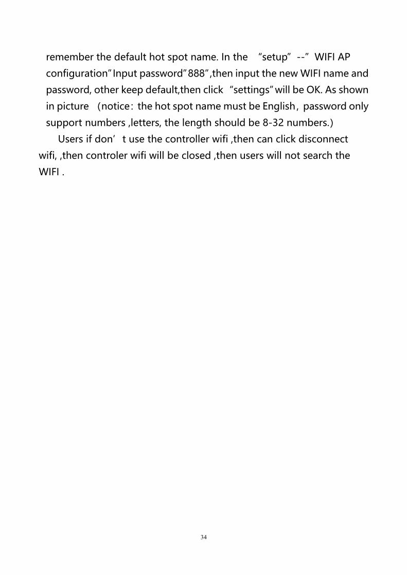
Step 2
Input network security secret key ,the original password is:the last 8
numbers of the bar code on the controller,then click “next step”,the
computer will connect with the Y controller WIFI,as shown in picture
32
Step 3
Computer connect with the controller WIFI hot spot ,then click the
LedshowYQ 2018 to add screen ,edit program and sending program etc.
Step 4
User can modify the hot spot name and password if not easy to
34
remember the default hot spot name. In the “setup”--”WIFI AP
configuration”Input password”888”,then input the new WIFI name and
password, other keep default,then click“settings”will be OK. As shown
in picture (notice:the hot spot name must be English,password only
support numbers ,letters, the length should be 8-32 numbers.)
Users if don’t use the controller wifi ,then can click disconnect
wifi, ,then controler wifi will be closed ,then users will not search the
WIFI .
35
33
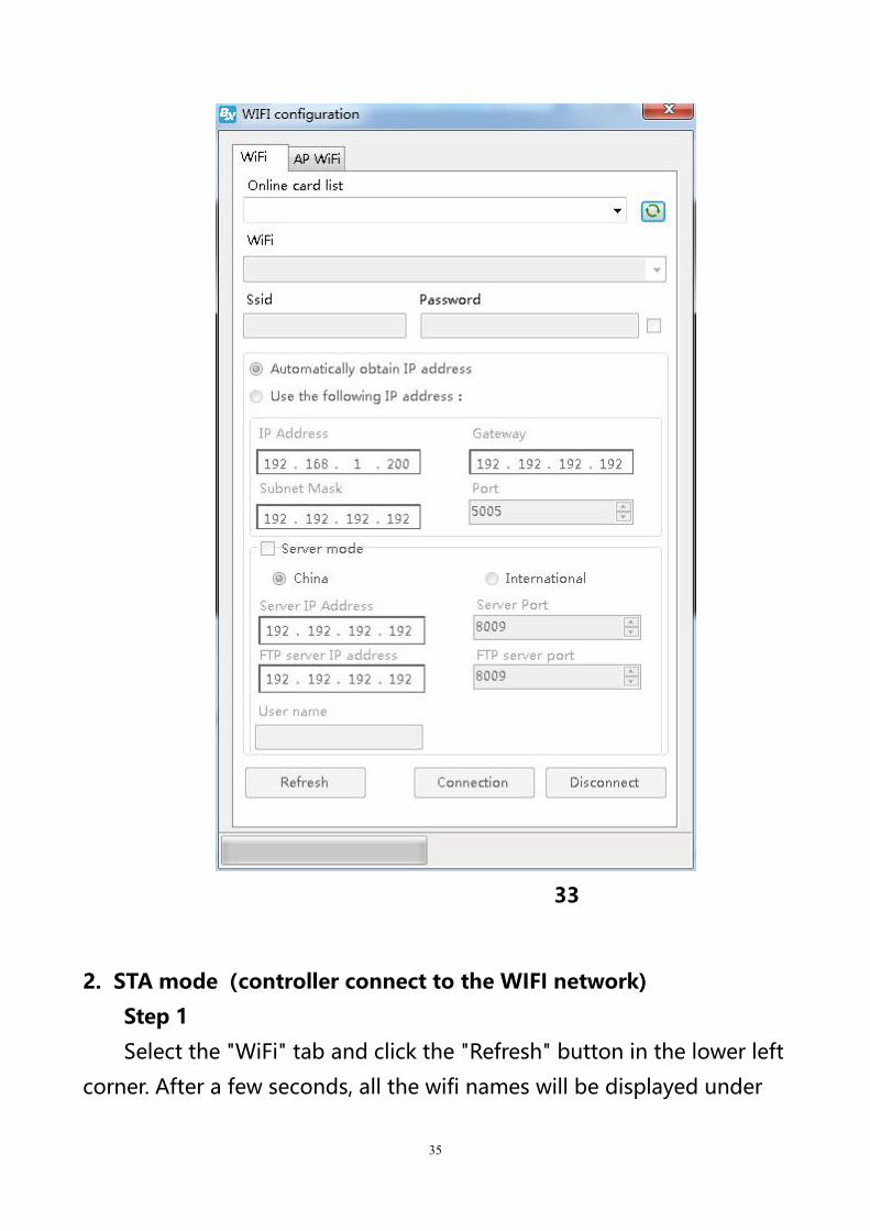
2. STA mode(controller connect to the WIFI network)
Step 1
Select the "WiFi" tab and click the "Refresh" button in the lower left
corner. After a few seconds, all the wifi names will be displayed under
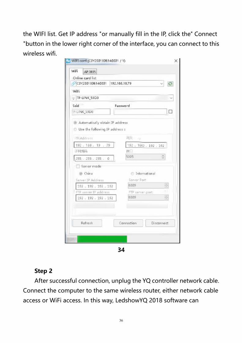
36
the WIFI list. Get IP address "or manually fill in the IP, click the" Connect
"button in the lower right corner of the interface, you can connect to this
wireless wifi.
34
Step 2
After successful connection, unplug the YQ controller network cable.
Connect the computer to the same wireless router, either network cable
access or WiFi access. In this way, LedshowYQ 2018 software can
37
communicate with YQ control card normally.Scan configuration
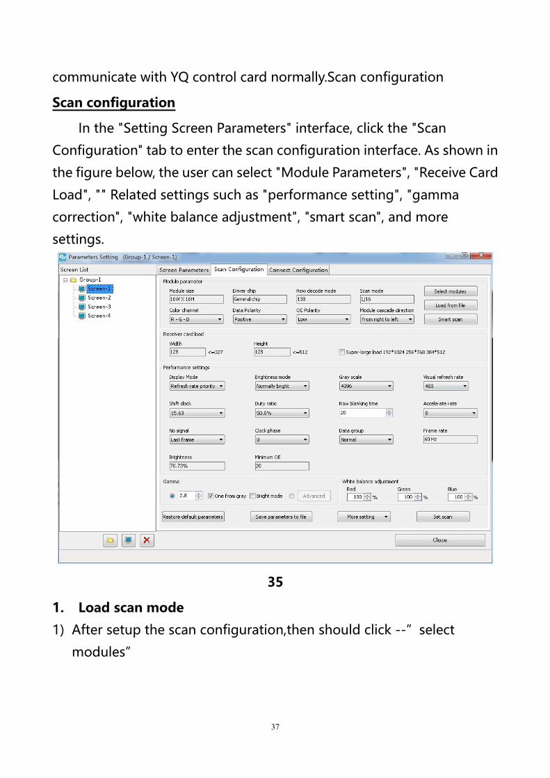
Scan configuration
In the "Setting Screen Parameters" interface, click the "Scan
Configuration" tab to enter the scan configuration interface. As shown in
the figure below, the user can select "Module Parameters", "Receive Card
Load", "" Related settings such as "performance setting", "gamma
correction", "white balance adjustment", "smart scan", and more
settings.
35
1. Load scan mode
1) After setup the scan configuration,then should click --”select
modules”
38
36
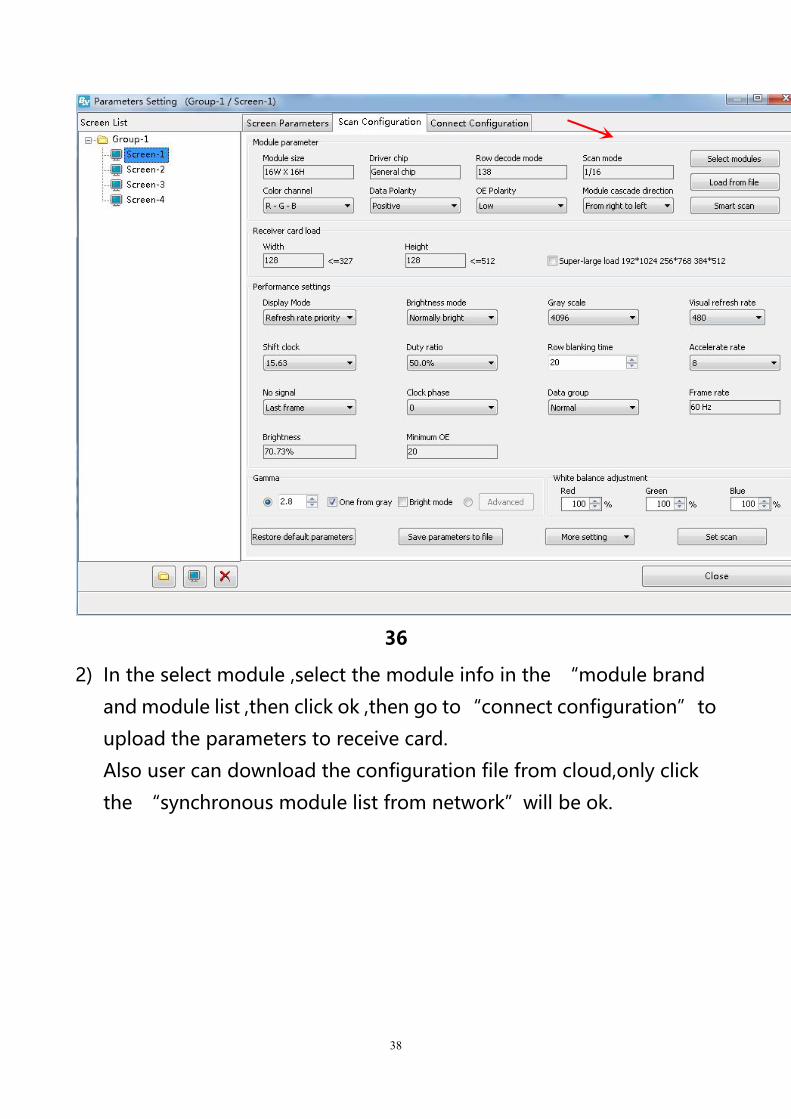
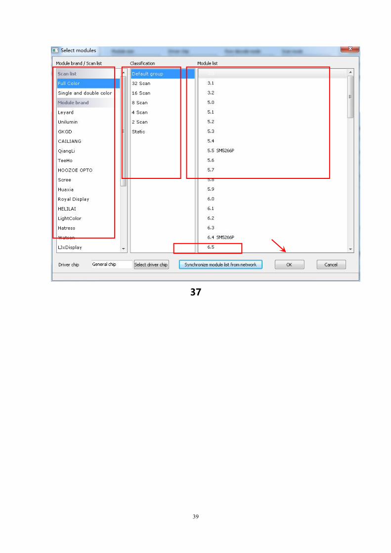
2) In the select module ,select the module info in the “module brand
and module list ,then click ok ,then go to“connect configuration”to
upload the parameters to receive card.
Also user can download the configuration file from cloud,only click
the “synchronous module list from network”will be ok.
39
37
40
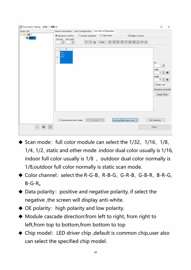
Scan mode:full color module can select the 1/32、1/16、1/8、
1/4、1/2、static and other mode .indoor dual color usually is 1/16,
indoor full color usually is 1/8 ,outdoor dual color normally is
1/8,outdoor full color normally is static scan mode.
Color channel:select the R-G-B、R-B-G、G-R-B、G-B-R、B-R-G、
B-G-R。
Data polarity:positive and negative polarity, if select the
negative ,the screen will display anti-white.
OE polarity:high polarity and low polarity.
Module cascade direction:from left to right, from right to
left,from top to bottom,from bottom to top
Chip model:LED driver chip ,default is common chip,user also
can select the specified chip model.
41
2. Smart scan configuration
When users don’t sure to use which scan mode ,then can select the
“smart scan configuration”
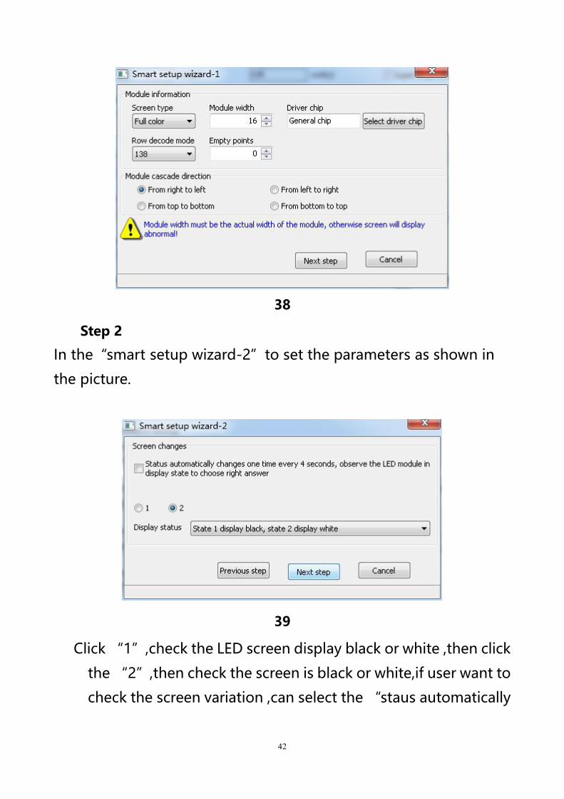
Step 1
Click “smart scan configuration”--”smart setup wizard-1”to
set the parameters.
Screen type:single color dual color and full color
Module width:user can input the module width according to the
LED screen total pixel for one line
Chip type:default is general chip ,also can specified the LED
screen chip.
Row decode mode:including no decode, 138 decode,74HC595
decode and RT5958 decode,usually select138 decode.
Empty points:when use empty points ,can input the empty
points numbers.
Module cascade direction:receiving card connection
direction :from right to left ,from left to right,from top to
bottom,from bottom to top.
After setup, pls click “next step”
42
38
Step 2
In the“smart setup wizard-2”to set the parameters as shown in
the picture.
39
Click “1”,check the LED screen display black or white ,then click
the “2”,then check the screen is black or white,if user want to
check the screen variation ,can select the “staus automatically
43
changes one time every 4 seconds ,observe the LED module in
display state to choose right answer ”then click “next step”
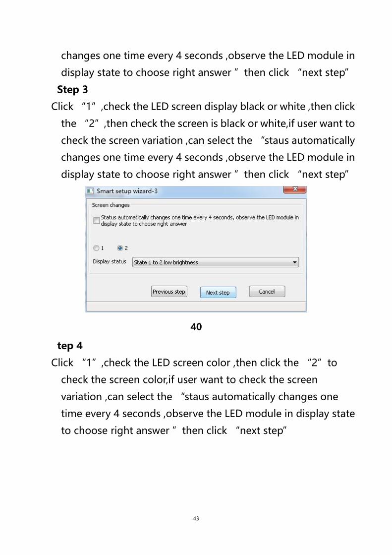
Step 3
Click “1”,check the LED screen display black or white ,then click
the “2”,then check the screen is black or white,if user want to
check the screen variation ,can select the “staus automatically
changes one time every 4 seconds ,observe the LED module in
display state to choose right answer ”then click “next step”
40
tep 4
Click “1”,check the LED screen color ,then click the “2”to
check the screen color,if user want to check the screen
variation ,can select the “staus automatically changes one
time every 4 seconds ,observe the LED module in display state
to choose right answer ”then click “next step”
44
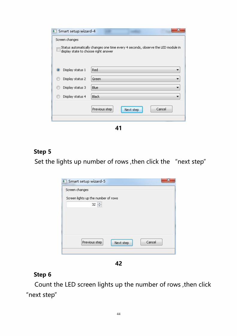
41
Step 5
Set the lights up number of rows ,then click the “next step”
42
Step 6
Count the LED screen lights up the number of rows ,then click
“next step”
45
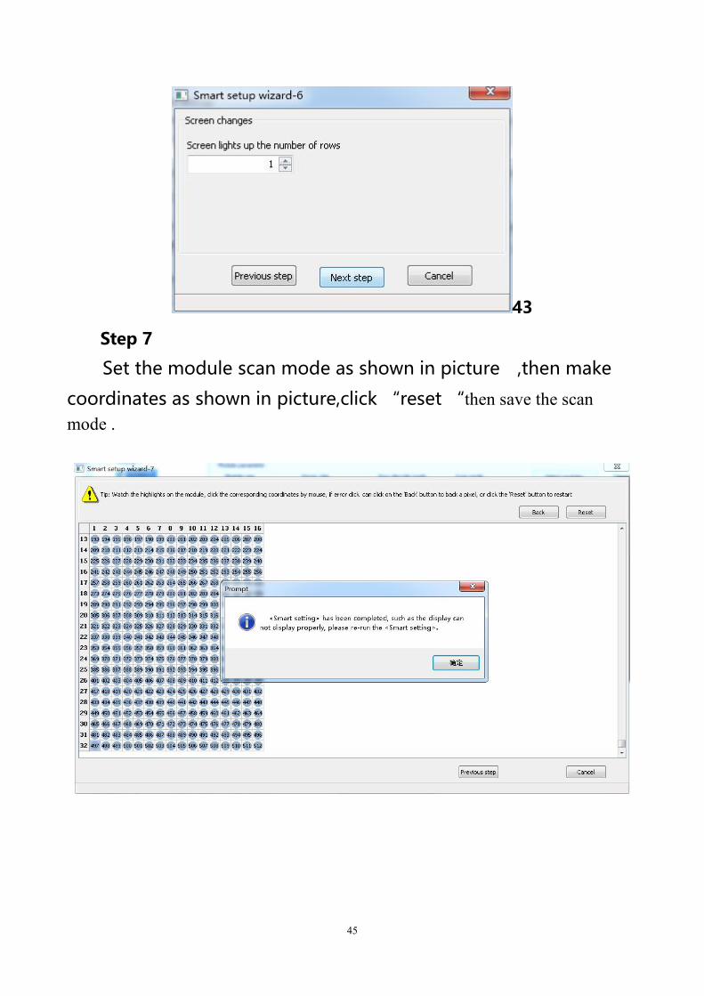
43
Step 7
Set the module scan mode as shown in picture ,then make
coordinates as shown in picture,click “reset “then save the scanmode .
46
44
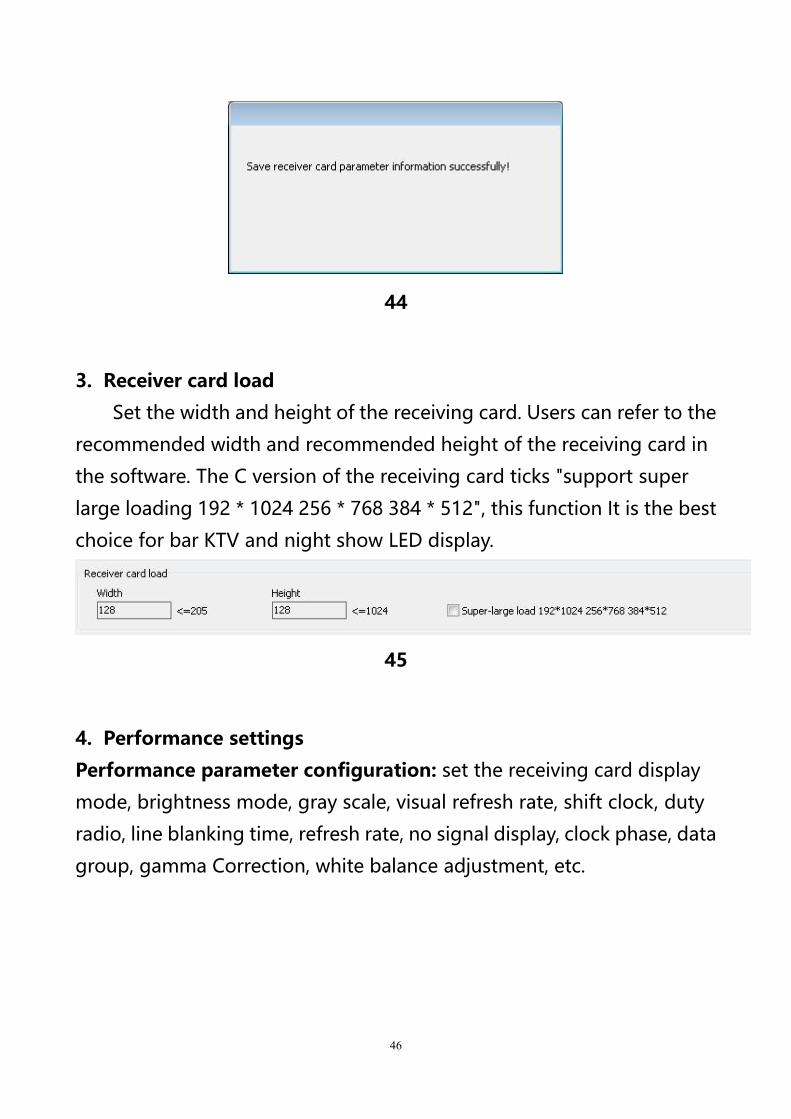
3. Receiver card load
Set the width and height of the receiving card. Users can refer to the
recommended width and recommended height of the receiving card in
the software. The C version of the receiving card ticks "support super
large loading 192 * 1024 256 * 768 384 * 512", this function It is the best
choice for bar KTV and night show LED display.
45
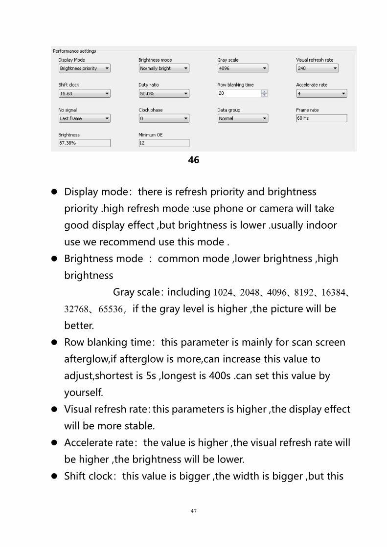
4. Performance settings
Performance parameter configuration: set the receiving card display
mode, brightness mode, gray scale, visual refresh rate, shift clock, duty
radio, line blanking time, refresh rate, no signal display, clock phase, data
group, gamma Correction, white balance adjustment, etc.
47
46
Display mode:there is refresh priority and brightness
priority .high refresh mode :use phone or camera will take
good display effect ,but brightness is lower .usually indoor
use we recommend use this mode .
Brightness mode :common mode ,lower brightness ,high
brightness
Gray scale:including 1024、2048、4096、8192、16384、
32768、65536,if the gray level is higher ,the picture will be
better.
Row blanking time:this parameter is mainly for scan screen
afterglow,if afterglow is more,can increase this value to
adjust,shortest is 5s ,longest is 400s .can set this value by
yourself.
Visual refresh rate:this parameters is higher ,the display effect
will be more stable.
Accelerate rate:the value is higher ,the visual refresh rate will
be higher ,the brightness will be lower.
Shift clock:this value is bigger ,the width is bigger ,but this
48
value is too high the screen will be blinking.
Duty ratio: if modify this data ,can make higher clock to the
scan shift clock ,usually is 50%.
Clock phase :the relative relationship about the shift clock
and shift data ,sometimes display picture have the blinking or
dislocation ,adjust this value can solve problem.
Max width:the receiver card control width value.
Brightness :the receiver card brightness efficiency
Min OE width:user can manually set the Min OE width.
5. Gamma
User can select the “Gamma”then input value,then select the
“one from gray”
6. White balance adjustment
When user want to use dark color ,can use this function to modify
the value ,if value is bigger ,then the color will be darker.
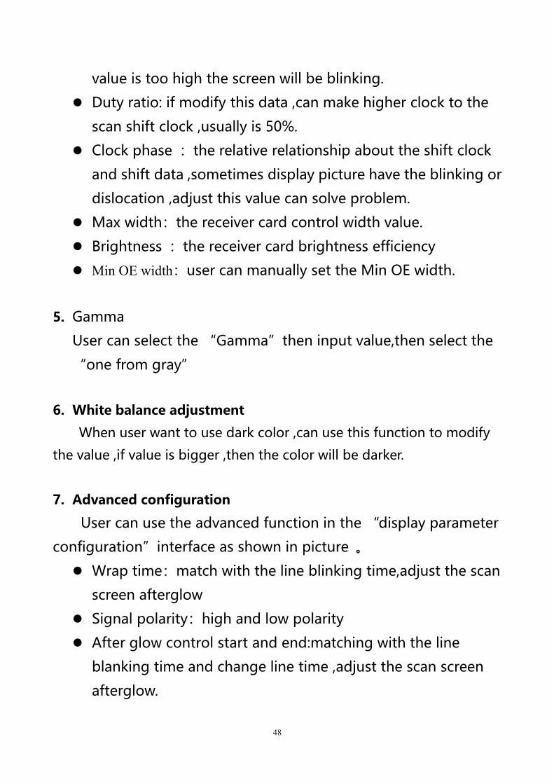
7. Advanced configuration
User can use the advanced function in the “display parameter
configuration”interface as shown in picture 。
Wrap time:match with the line blinking time,adjust the scan
screen afterglow
Signal polarity:high and low polarity
After glow control start and end:matching with the line
blanking time and change line time ,adjust the scan screen
afterglow.
49
47
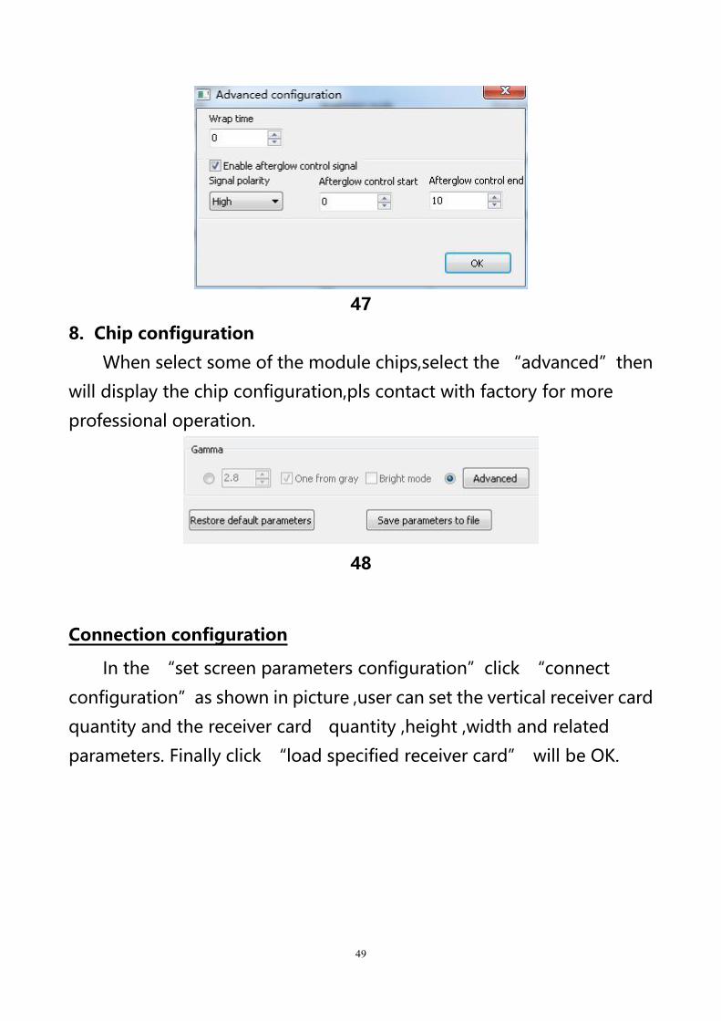
8. Chip configuration
When select some of the module chips,select the “advanced”then
will display the chip configuration,pls contact with factory for more
professional operation.
48
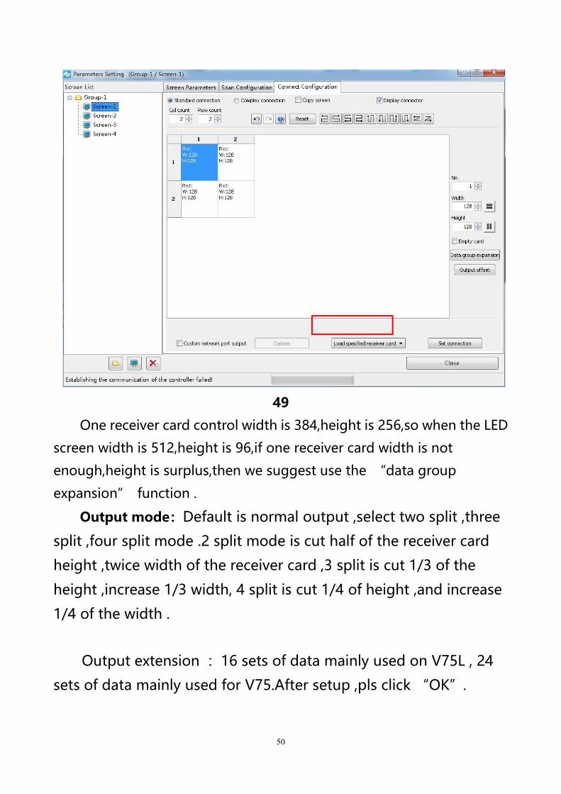
Connection configuration
In the “set screen parameters configuration”click “connect
configuration”as shown in picture ,user can set the vertical receiver card
quantity and the receiver card quantity ,height ,width and related
parameters. Finally click “load specified receiver card” will be OK.
50
49
One receiver card control width is 384,height is 256,so when the LED
screen width is 512,height is 96,if one receiver card width is not
enough,height is surplus,then we suggest use the “data group
expansion” function .
Output mode:Default is normal output ,select two split ,three
split ,four split mode .2 split mode is cut half of the receiver card
height ,twice width of the receiver card ,3 split is cut 1/3 of the
height ,increase 1/3 width, 4 split is cut 1/4 of height ,and increase
1/4 of the width .
Output extension :16 sets of data mainly used on V75L , 24
sets of data mainly used for V75.After setup ,pls click “OK”.
51
50
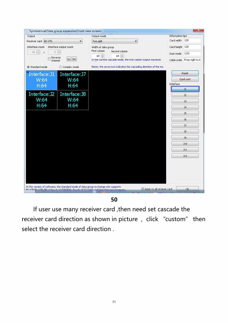
If user use many receiver card ,then need set cascade the
receiver card direction as shown in picture ,click “custom” then
select the receiver card direction .
52
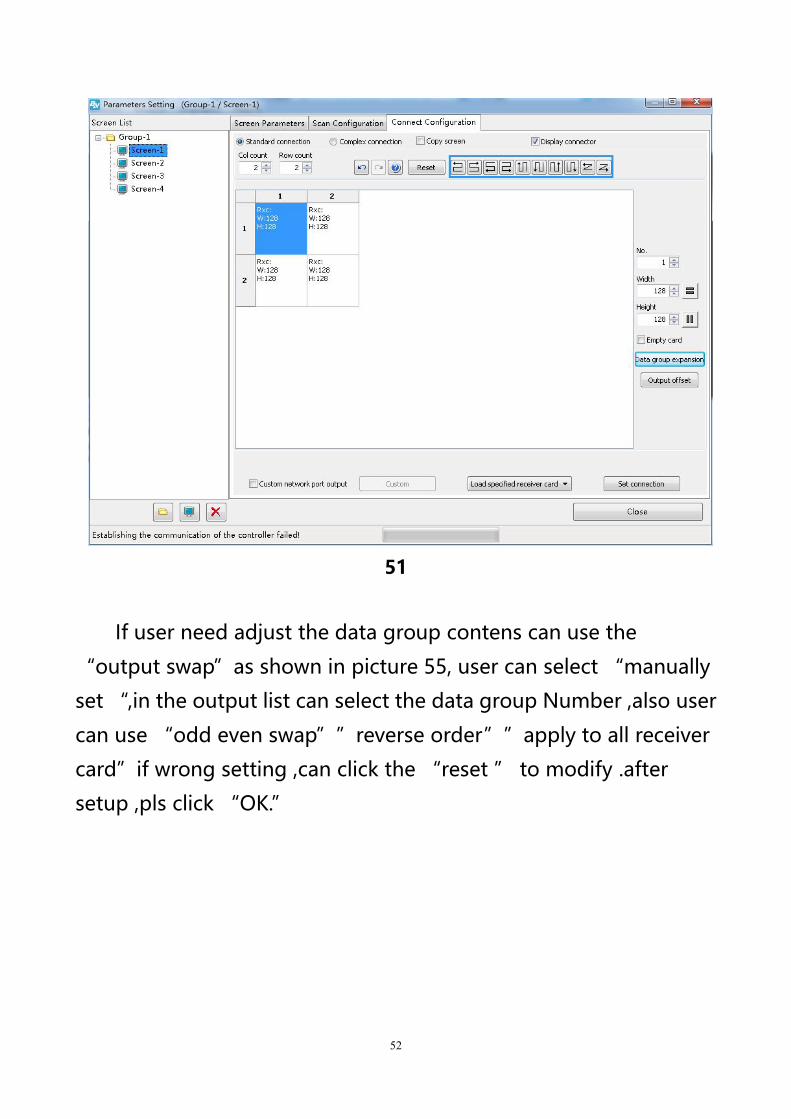
51
If user need adjust the data group contens can use the
“output swap”as shown in picture 55, user can select “manually
set “,in the output list can select the data group Number ,also user
can use “odd even swap””reverse order””apply to all receiver
card”if wrong setting ,can click the “reset ” to modify .after
setup ,pls click “OK.”
53
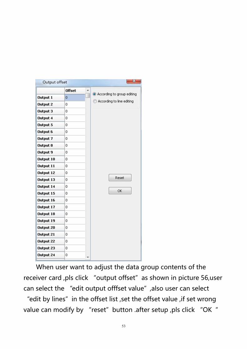
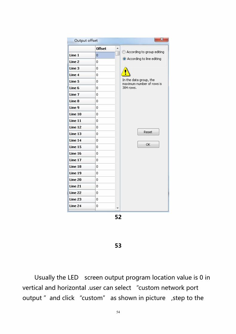
When user want to adjust the data group contents of the
receiver card ,pls click “output offset”as shown in picture 56,user
can select the “edit output offfset value”,also user can select
“edit by lines”in the offset list ,set the offset value ,if set wrong
value can modify by “reset”button .after setup ,pls click “OK“
54
52
53
Usually the LED screen output program location value is 0 in
vertical and horizontal .user can select “custom network port
output ”and click “custom” as shown in picture ,step to the
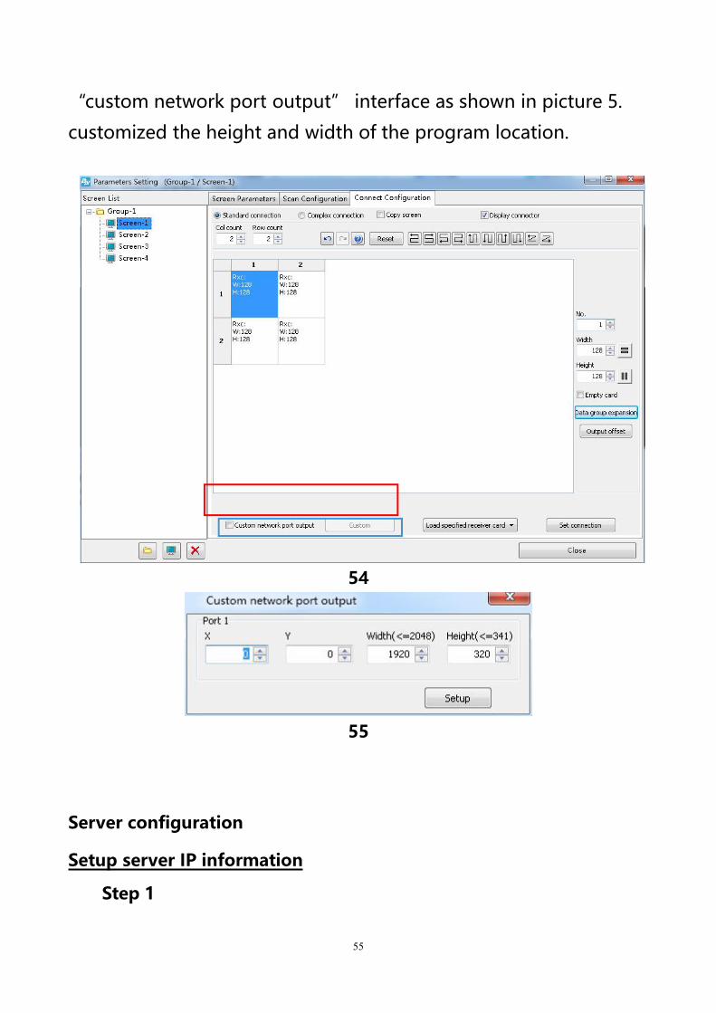
55
“custom network port output” interface as shown in picture 5.
customized the height and width of the program location.
54
55
Server configuration
Setup server IP information
Step 1
56
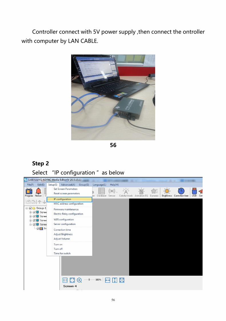
Controller connect with 5V power supply ,then connect the ontroller
with computer by LAN CABLE.
56
Step 2
Select “IP configuration ”as below
57
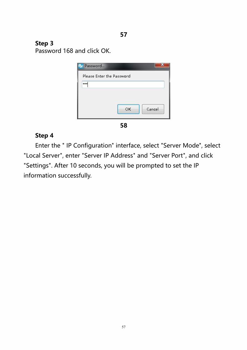
57Step 3Password 168 and click OK.
58
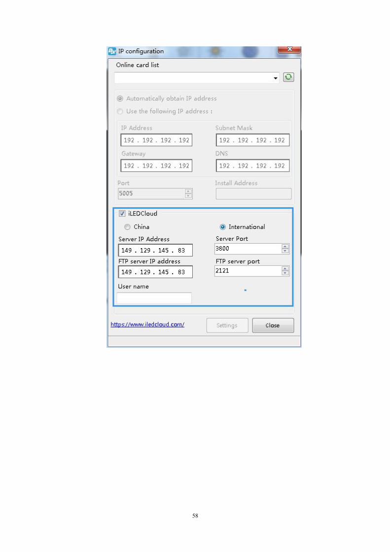
Step 4
Enter the " IP Configuration" interface, select "Server Mode", select
"Local Server", enter "Server IP Address" and "Server Port", and click
"Settings". After 10 seconds, you will be prompted to set the IP
information successfully.
58
59
59
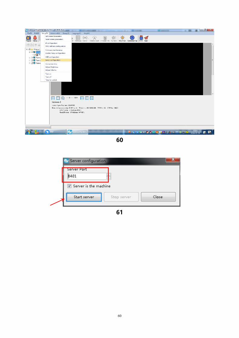
Step 5
Click the setting menu and select the "Server Configuration" option,
as shown in the figure below. Enter the password "168", enter the
"Server Configuration" interface, enter the "Server Port" number, the
server port number here is the "Server Port" number entered by Step 4
in the "Controller IP Settings" interface, click "Start Server" , Wait for the
red icon " " in front of the screen to change to the blue " " to indicate
that the server is online, and the server settings are completed.
60
60
61

61
Controller connect to the wireless router
After set the controller IP ,we should remove the computer networkcable ,then connect with router .usually we use two kinds of router ,3Gindustrial wireless router and 3G/4G industrial router, users can set according todifferent router model.
1.Connect the 3G industrial wireless router
Step 1Insert the SIM card to 3G wireless industrial router ,connect thereceiver then use 5V power to connect with the router,as shown inpicture 。
62
62
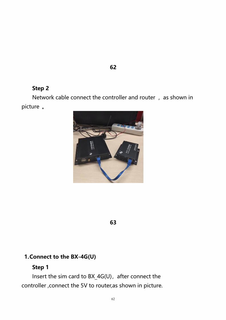
Step 2
Network cable connect the controller and router ,as shown in
picture 。
63
1.Connect to the BX-4G(U)
Step 1
Insert the sim card to BX_4G(U),after connect the
controller ,connect the 5V to router,as shown in picture.
63
64
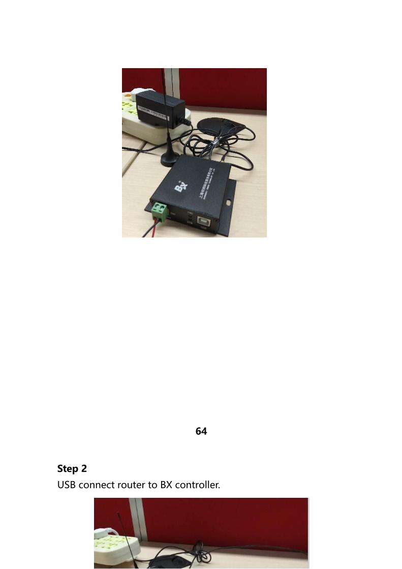
Step 2
USB connect router to BX controller.
64
65
Step 3
After controller connect with the 3G/4G industrial router ,if u use the
router for network , should check if the router have the” NetSniper”
function or not ,must close the NetSniper function ,if not ,the controller
can’t communicate successfully.as shown in picture 。
65
66
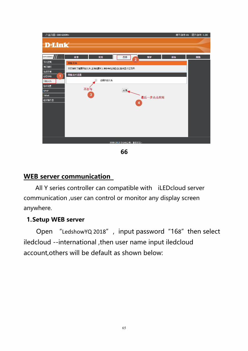
WEB server communication
All Y series controller can compatible with iLEDcloud server
communication ,user can control or monitor any display screen
anywhere.
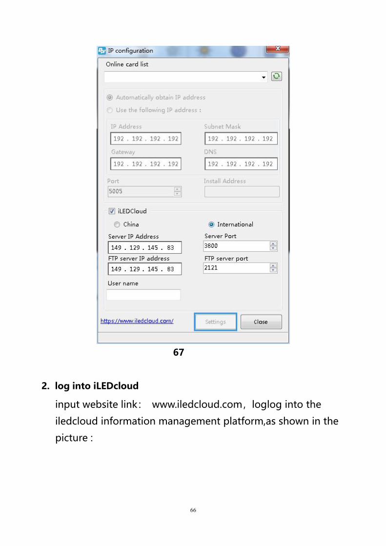
1.Setup WEB server
Open “LedshowYQ 2018”,input password“168”then select
iledcloud --international ,then user name input iledcloud
account,others will be default as shown below:
66
67
2. log into iLEDcloud
input website link: www.iledcloud.com,loglog into the
iledcloud information management platform,as shown in the
picture :
67
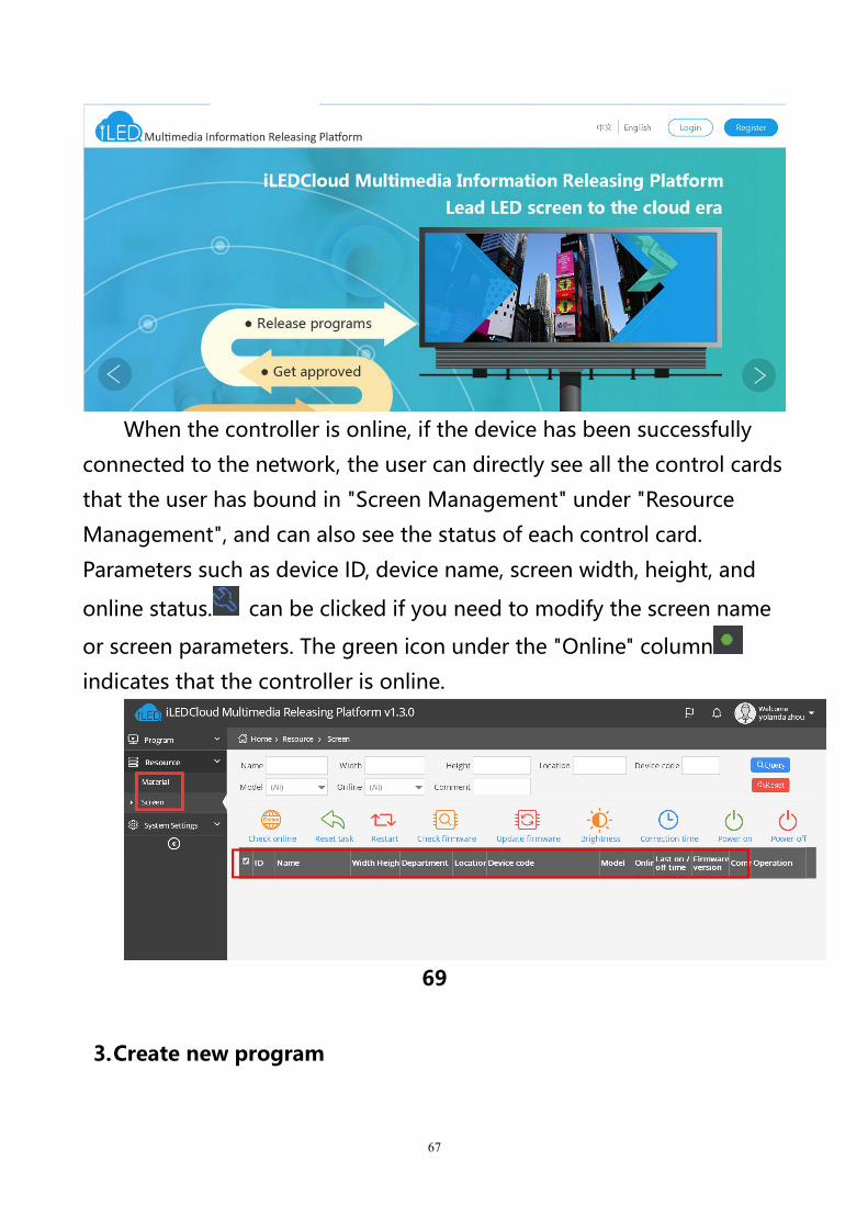
When the controller is online, if the device has been successfully
connected to the network, the user can directly see all the control cards
that the user has bound in "Screen Management" under "Resource
Management", and can also see the status of each control card.
Parameters such as device ID, device name, screen width, height, and
online status. can be clicked if you need to modify the screen name
or screen parameters. The green icon under the "Online" column
indicates that the controller is online.
69
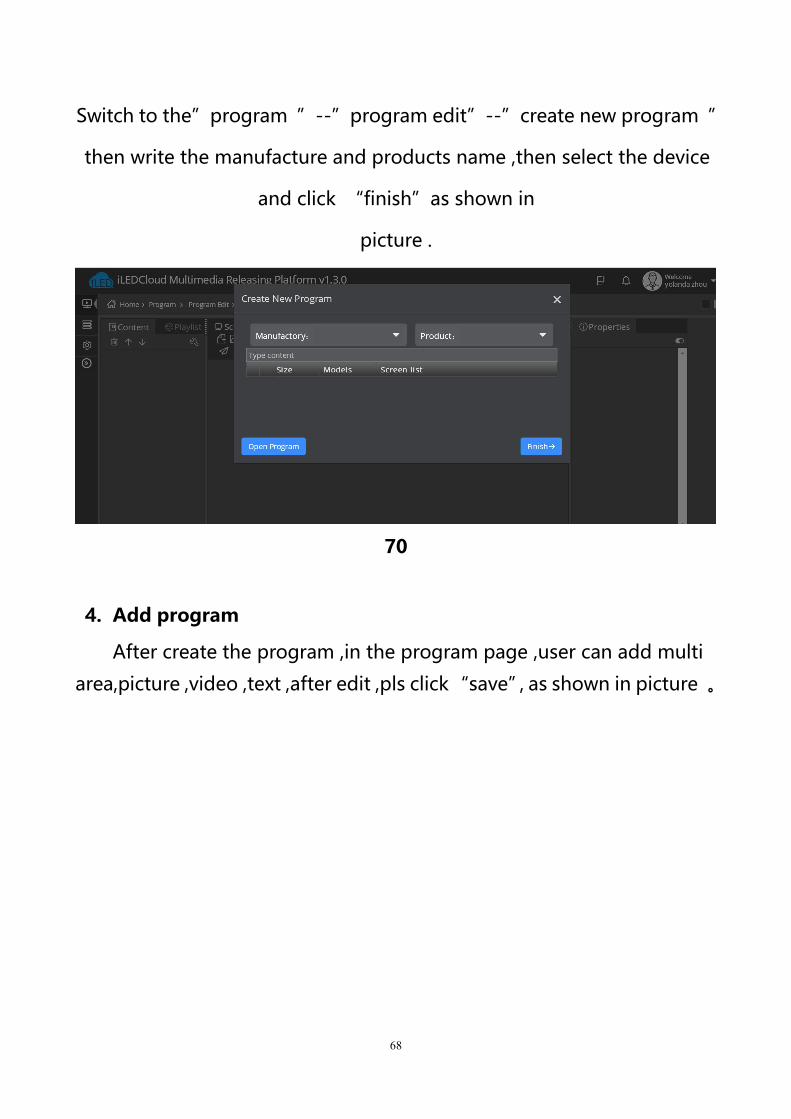
3.Create new program
68
Switch to the”program ”--”program edit”--”create new program ”
then write the manufacture and products name ,then select the device
and click “finish”as shown in
picture .
70
4. Add program
After create the program ,in the program page ,user can add multi
area,picture ,video ,text ,after edit ,pls click“save”,as shown in picture 。
69
////////
71
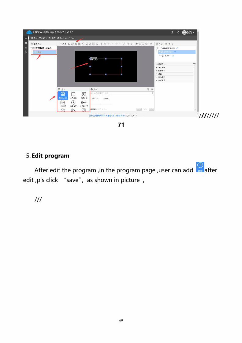
5. Edit program
After edit the program ,in the program page ,user can add after
edit ,pls click “save”,as shown in picture 。
///
70
72
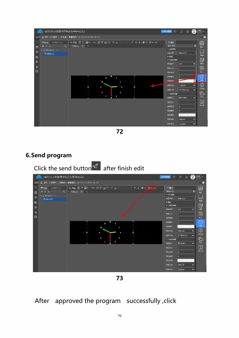
6.Send program
Click the send button after finish edit
73
After approved the program successfully ,click

71
“program”--”program release ”find the released program
(program name or ID)as shown in picture 。
74
72
ADD PROGRAM STEPS
EXAMPLE
Add program
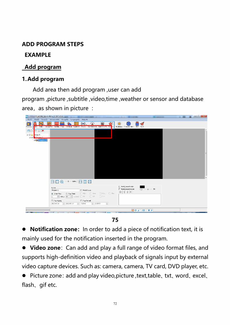
1.Add program
Add area then add program ,user can add
program ,picture ,subtitle ,video,time ,weather or sensor and database
area,as shown in picture :
75
Notification zone:In order to add a piece of notification text, it is
mainly used for the notification inserted in the program.
Video zone:Can add and play a full range of video format files, and
supports high-definition video and playback of signals input by external
video capture devices. Such as: camera, camera, TV card, DVD player, etc.
Picture zone:add and play video,picture ,text,table、txt、word、excel、
flash、gif etc.
73
Subtitle zone:add one line simply format word
Time zone:display time/dial/lunar/ timer count up/timer count down
Weather zone:support all area weather value
Sensor zone:display temp、humidity,noisy ,water ,liquid and
PM2.5 value, PM10 value, wind speed, wind direction, atmospheric
pressure, light, negative ion and TSP value.
Database zone:visit mysql or sqlserver,display specified data
content of the database.
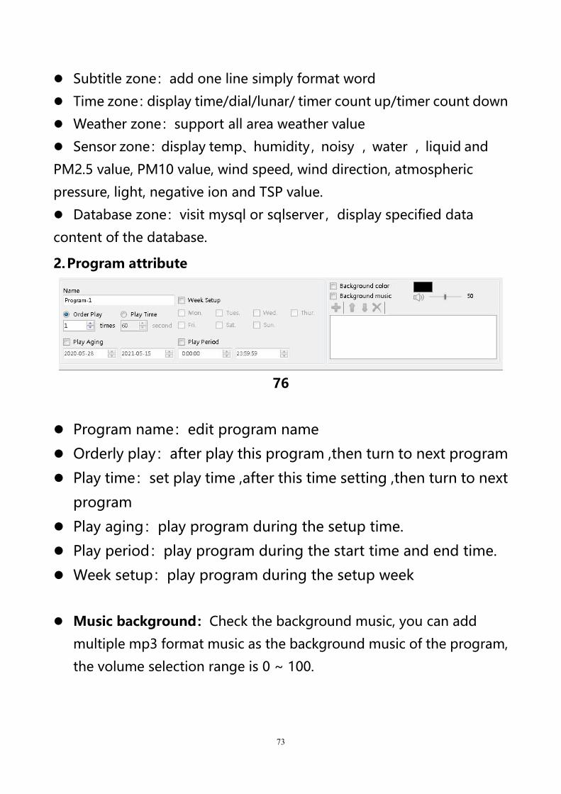
2.Program attribute
76
Program name:edit program name
Orderly play:after play this program ,then turn to next program
Play time:set play time ,after this time setting ,then turn to next
program
Play aging:play program during the setup time.
Play period:play program during the start time and end time.
Week setup:play program during the setup week
Music background:Check the background music, you can add
multiple mp3 format music as the background music of the program,
the volume selection range is 0 ~ 100.

74
Add picture zone
1.Add picture zone
Add zone ,user can click “edit”in the menu to add picture zonealso .after add the picture zone ,add file to display as shown in picture ,
after add picture ,the LED screen and preview area will display at
same time ,then user can modify the program as needed.
User can use the tools to modify the picture size and location.
2.Picture zone attribute
78
name:user can distinguish file name by this ,can modify by
manual.
X:file left up corner to the LED screen left boarder location ,unit
is pixel.
Y:file left up corner to the LED screen up boarder location ,unit is
pixel.
Width:file area width ,unit is pixel
Height :file area height ,unit is pixel
75
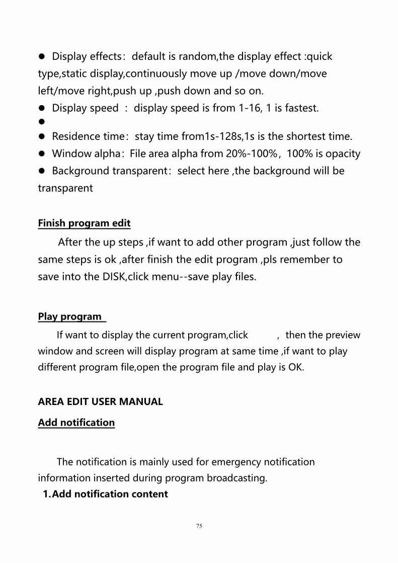
Display effects:default is random,the display effect :quick
type,static display,continuously move up /move down/move
left/move right,push up ,push down and so on.
Display speed :display speed is from 1-16, 1 is fastest.
Residence time:stay time from1s-128s,1s is the shortest time.
Window alpha:File area alpha from 20%-100%,100% is opacity
Background transparent:select here ,the background will be
transparent
Finish program edit
After the up steps ,if want to add other program ,just follow the
same steps is ok ,after finish the edit program ,pls remember to
save into the DISK,click menu--save play files.
Play program
If want to display the current program,click ,then the preview
window and screen will display program at same time ,if want to play
different program file,open the program file and play is OK.
AREA EDIT USER MANUAL
Add notification
The notification is mainly used for emergency notification
information inserted during program broadcasting.
1.Add notification content

76
Click the main toolbar button to add one or more notifications.
Edit the notification content directly in the edit box of the notification
properties area. Users can set display attributes such as play period, text
font, font size, text color, background color, and transparent background.
79
2.Notification attribute
In the notification properties area, you can set the display position,
width, height, display effects, running speed, dwell time, and whether to
display text on the screen. And can choose whether voice broadcast,
voice playback sound type, digital reading, playback interval, broadcast
volume and so on.
80
3.Play/delete notification
After everything is set, click the Send button to play the
notification, select "Notification", click the right mouse button, and click
"Delete" to delete the notification.
77
Play video
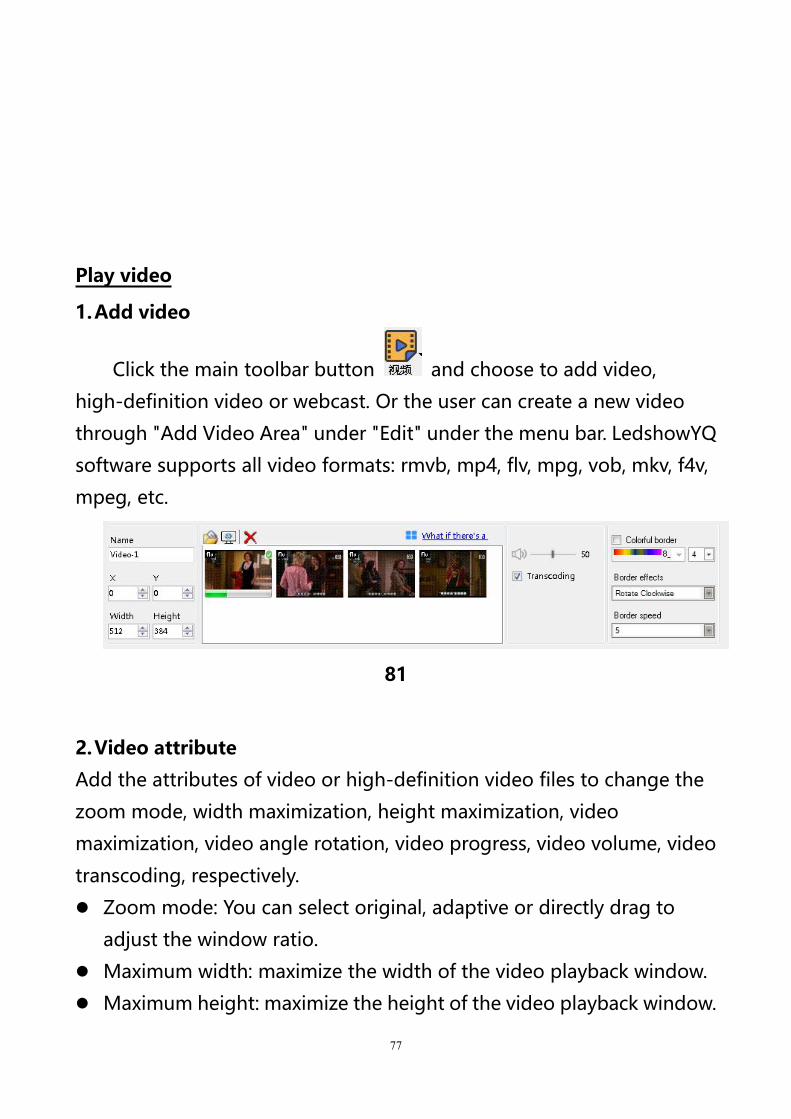
1.Add video
Click the main toolbar button and choose to add video,
high-definition video or webcast. Or the user can create a new video
through "Add Video Area" under "Edit" under the menu bar. LedshowYQ
software supports all video formats: rmvb, mp4, flv, mpg, vob, mkv, f4v,
mpeg, etc.
81
2.Video attribute
Add the attributes of video or high-definition video files to change the
zoom mode, width maximization, height maximization, video
maximization, video angle rotation, video progress, video volume, video
transcoding, respectively.
Zoom mode: You can select original, adaptive or directly drag to
adjust the window ratio.
Maximum width: maximize the width of the video playback window.
Maximum height: maximize the height of the video playback window.
78
Video maximization: maximize the video playback window.
Video angle rotation: Click once to rotate the video playback window
by 90 degrees.
Video progress: Users can drag the progress bar by themselves to
fast forward or rewind the program.
Video volume: change the video file volume 0-100.
Whether transcoding: When the video on the computer can be
previewed and cannot be displayed on the LED screen, you can check
transcoding to convert individual special video formats transcoding
so that the video can be played normally.
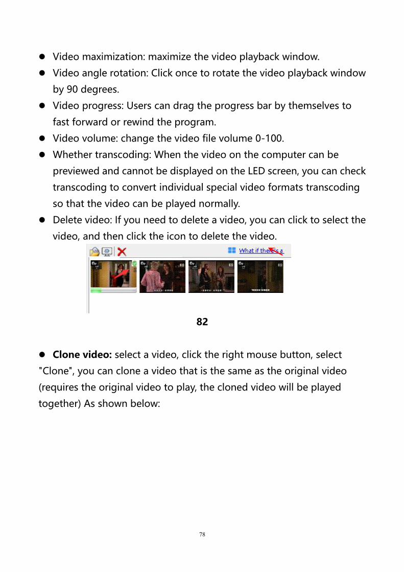
Delete video: If you need to delete a video, you can click to select the
video, and then click the icon to delete the video.
82
Clone video: select a video, click the right mouse button, select
"Clone", you can clone a video that is the same as the original video
(requires the original video to play, the cloned video will be played
together) As shown below:
79
83
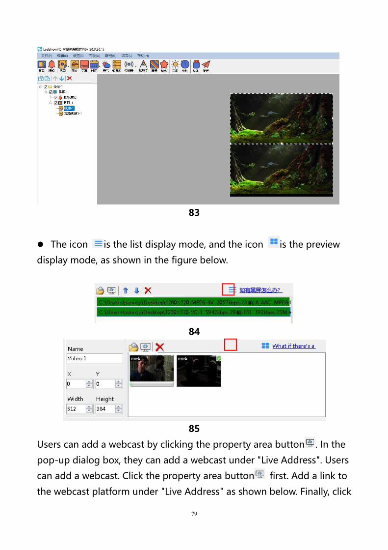
The icon is the list display mode, and the icon is the preview
display mode, as shown in the figure below.
84
85
Users can add a webcast by clicking the property area button . In the
pop-up dialog box, they can add a webcast under "Live Address". Users
can add a webcast. Click the property area button first. Add a link to
the webcast platform under "Live Address" as shown below. Finally, click
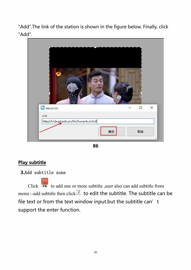
80
"Add".The link of the station is shown in the figure below. Finally, click
"Add".
86
Play subtitle
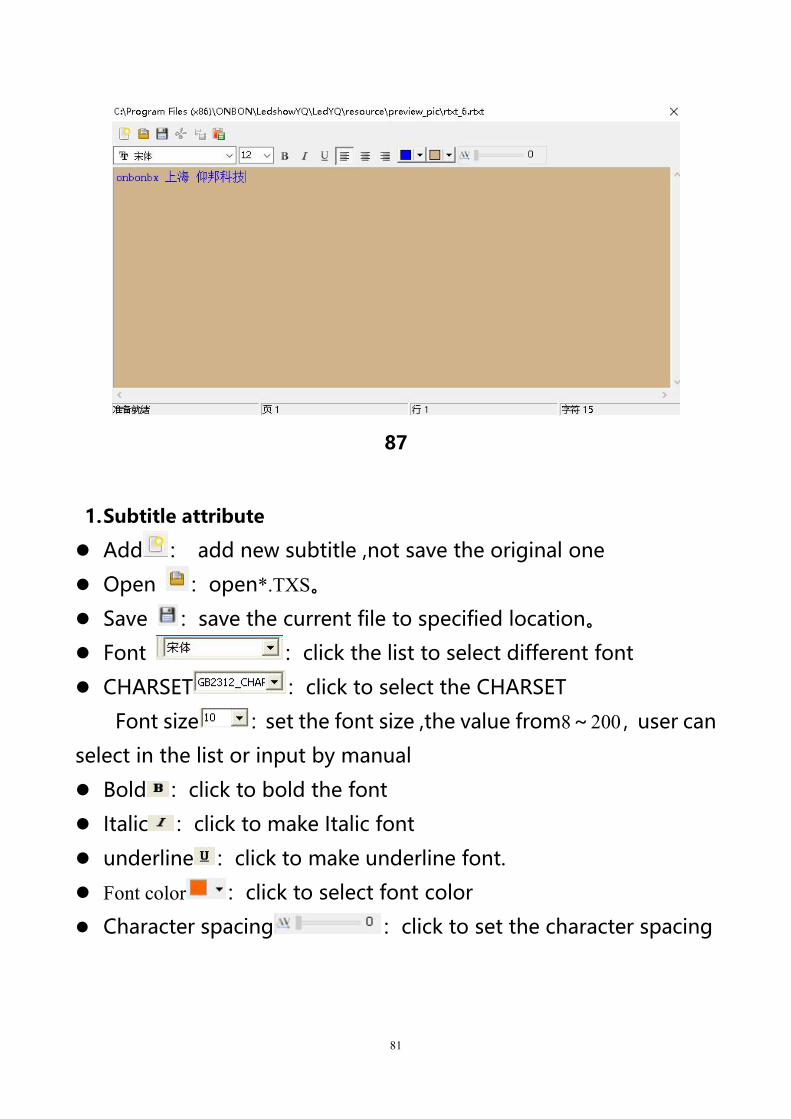
3.Add subtitle zone
Click to add one or more subtitle ,user also can add subtitle frommenu --add subtitle then click to edit the subtitle. The subtitle can be
file text or from the text window input.but the subtitle can’t
support the enter function.
81
87
1.Subtitle attribute
Add : add new subtitle ,not save the original one
Open :open*.TXS。
Save :save the current file to specified location。
Font :click the list to select different font
CHARSET :click to select the CHARSET
Font size :set the font size ,the value from8~200,user can
select in the list or input by manual
Bold :click to bold the font
Italic :click to make Italic font
underline :click to make underline font.
Font color :click to select font color
Character spacing :click to set the character spacing
82
TIME
1.Add time
Click in the menu,select the time ,lunar or timer ,also user can
select the “edit”--select the time zone ,dial zone ,lunar zone or timer
zone.
2.Time attribute
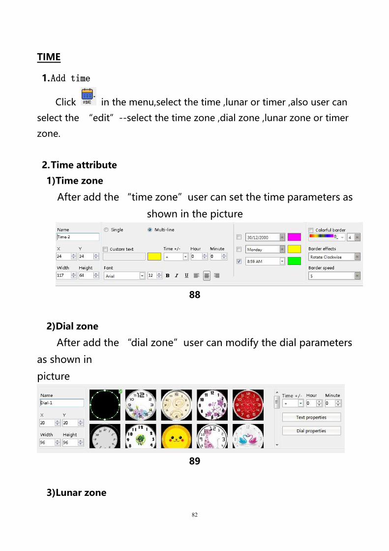
1)Time zone
After add the “time zone”user can set the time parameters as
shown in the picture
88
2)Dial zone
After add the “dial zone”user can modify the dial parameters
as shown in
picture
89
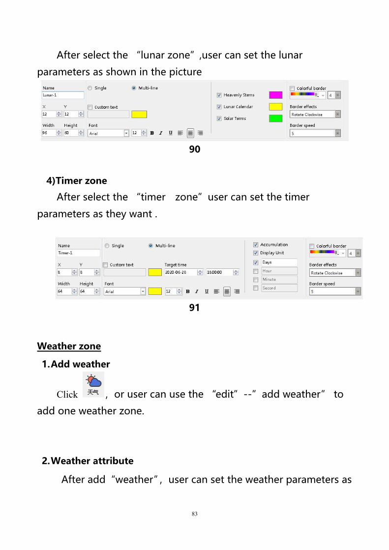
3)Lunar zone
83
After select the “lunar zone”,user can set the lunar
parameters as shown in the picture
90
4)Timer zone
After select the “timer zone”user can set the timer
parameters as they want .
91
Weather zone
1.Add weather
Click ,or user can use the “edit”--”add weather” to
add one weather zone.
2.Weather attribute
After add“weather”,user can set the weather parameters as
84
shown in the picture .
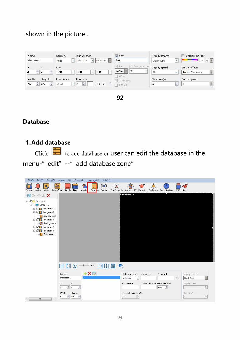
92
Database
1.Add database
Click to add database or user can edit the database in the
menu-”edit”--”add database zone”
85
93
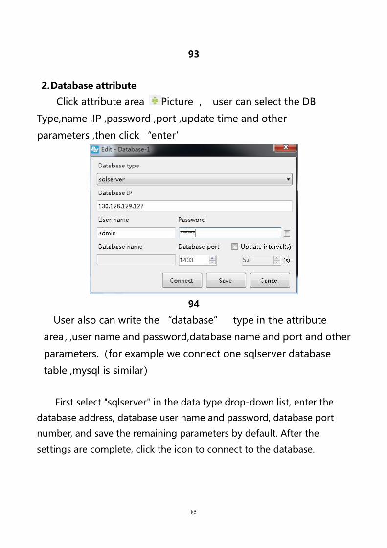
2.Database attribute
Click attribute area Picture , user can select the DB
Type,name ,IP ,password ,port ,update time and other
parameters ,then click “enter’
94
User also can write the “database” type in the attribute
area,,user name and password,database name and port and other
parameters.(for example we connect one sqlserver database
table ,mysql is similar)
First select "sqlserver" in the data type drop-down list, enter the
database address, database user name and password, database port
number, and save the remaining parameters by default. After the
settings are complete, click the icon to connect to the database.
86
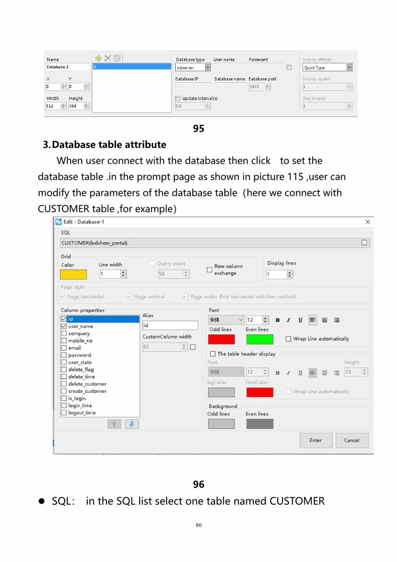
95
3.Database table attribute
When user connect with the database then click to set the
database table .in the prompt page as shown in picture 115 ,user can
modify the parameters of the database table(here we connect with
CUSTOMER table ,for example)
96
SQL: in the SQL list select one table named CUSTOMER

87
Grid color:set the database table color ,here is default.
Line height:line height for the database gird ,here is default
Line width:line width for the database gird ,here is default
Display lines:line numbers or the database gird ,here is default
Background:user select one of pictures as the database
background
Column property: user can select the “column property”as
shown in picture 115,here we select three column name
Wrap line automatically:after selected , the database gird size
and contents will change line automatically
Column font size:set the column font size ,here is default.
Bold:set the font size as bold ,here is default
Italic :set the font size as italic ,here is default
Underline :set the font size as bold ,here is default
Left aligned \centered \ right alignment: set the column text
alignment to left, center or right alignment.Select the default here.
Background color:user can set the column odd lines and Even
lines background color ,here select the default.
Column font color:set column font color ,now odd lines select
red color ,the Even lines select the blue color
After setup the attribute as shown in picture 116, we wish to named
the gird as CUSTOMER,the gird lines is yellow ,line height is
23,line width is 1 ,display the first three columns,the odd lines is
red color ,the even lines is blue ,other value is default.
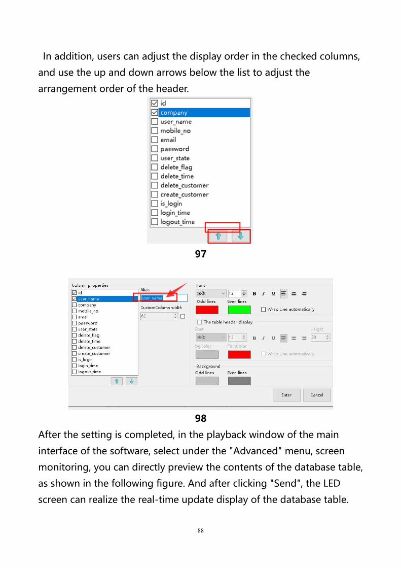
88
In addition, users can adjust the display order in the checked columns,
and use the up and down arrows below the list to adjust the
arrangement order of the header.
97
98
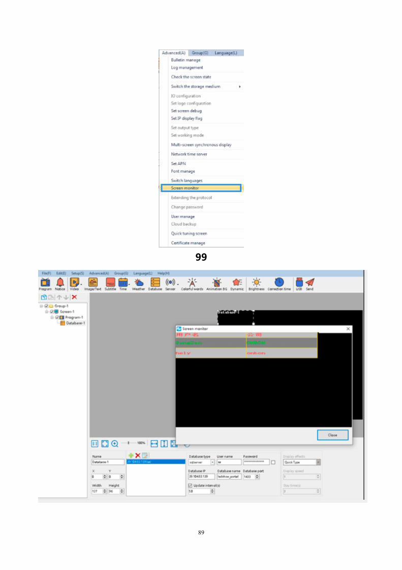
After the setting is completed, in the playback window of the main
interface of the software, select under the "Advanced" menu, screen
monitoring, you can directly preview the contents of the database table,
as shown in the following figure. And after clicking "Send", the LED
screen can realize the real-time update display of the database table.
89
99
90
100
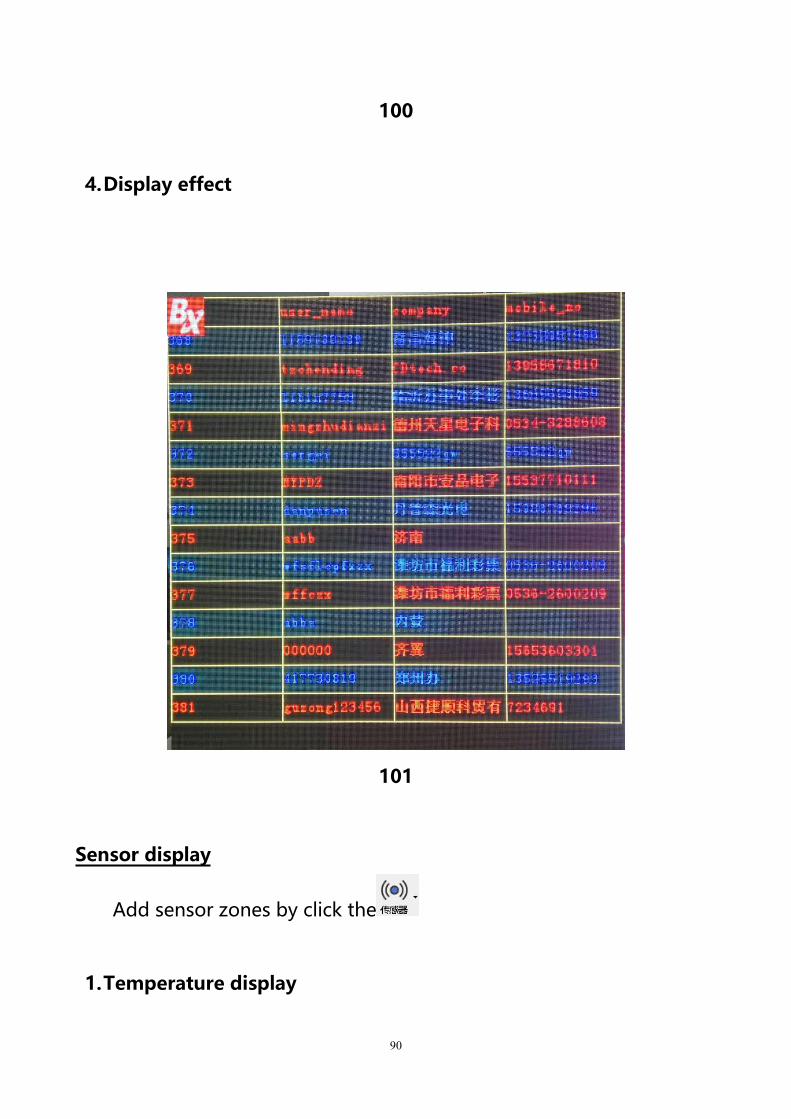
4.Display effect
101
Sensor display
Add sensor zones by click the
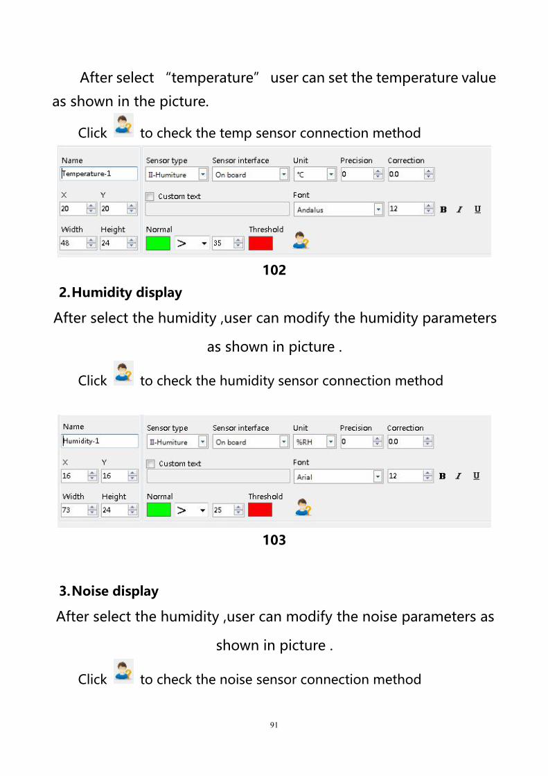
1.Temperature display
91
After select “temperature” user can set the temperature value
as shown in the picture.
Click to check the temp sensor connection method
102
2.Humidity display
After select the humidity ,user can modify the humidity parameters
as shown in picture .
Click to check the humidity sensor connection method
103
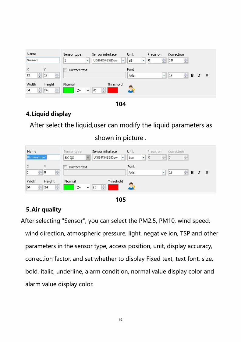
3.Noise display
After select the humidity ,user can modify the noise parameters as
shown in picture .
Click to check the noise sensor connection method
92
104
4.Liquid display
After select the liquid,user can modify the liquid parameters as
shown in picture .
105
5.Air quality
After selecting "Sensor", you can select the PM2.5, PM10, wind speed,
wind direction, atmospheric pressure, light, negative ion, TSP and other
parameters in the sensor type, access position, unit, display accuracy,
correction factor, and set whether to display Fixed text, text font, size,
bold, italic, underline, alarm condition, normal value display color and
alarm value display color.
93
Colorful words
1.add colorful words
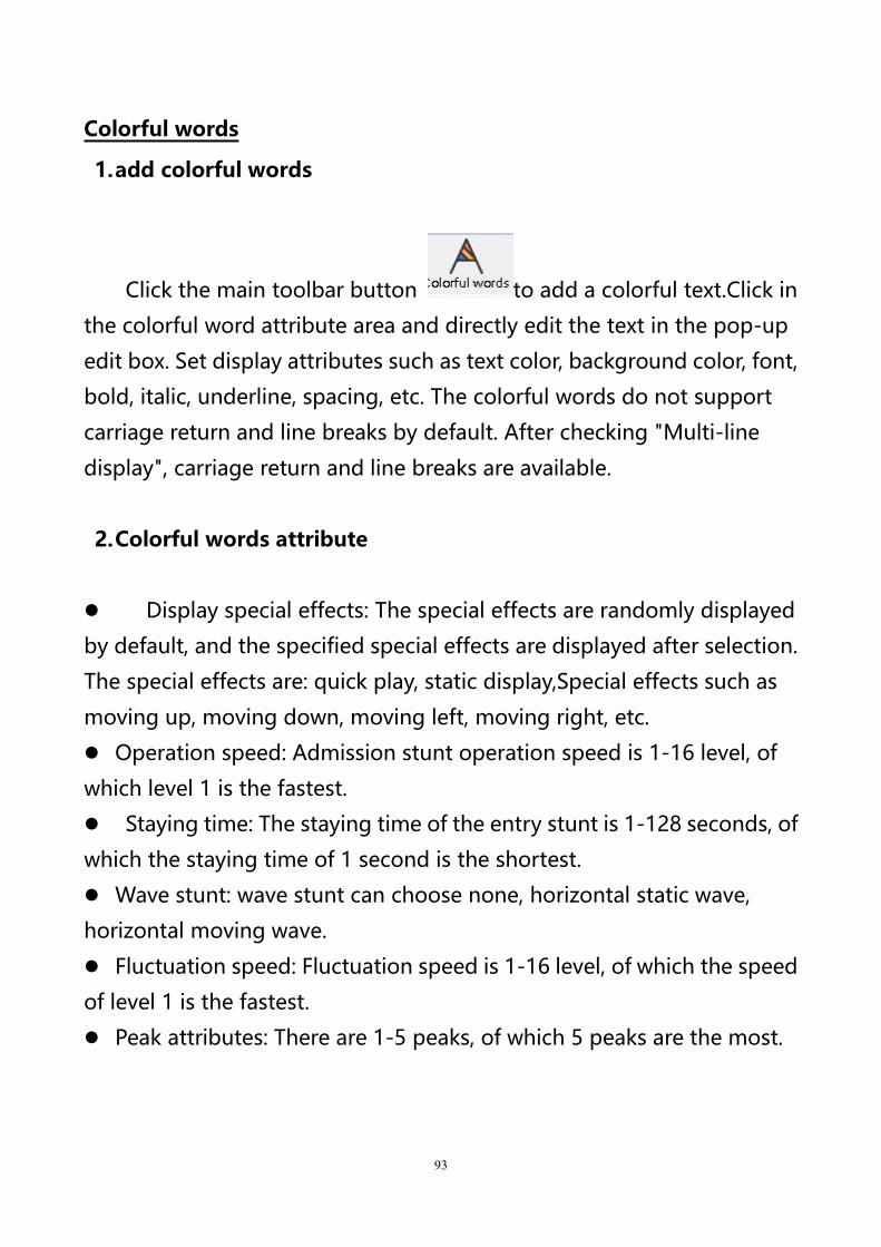
Click the main toolbar button to add a colorful text.Click in
the colorful word attribute area and directly edit the text in the pop-up
edit box. Set display attributes such as text color, background color, font,
bold, italic, underline, spacing, etc. The colorful words do not support
carriage return and line breaks by default. After checking "Multi-line
display", carriage return and line breaks are available.
2.Colorful words attribute
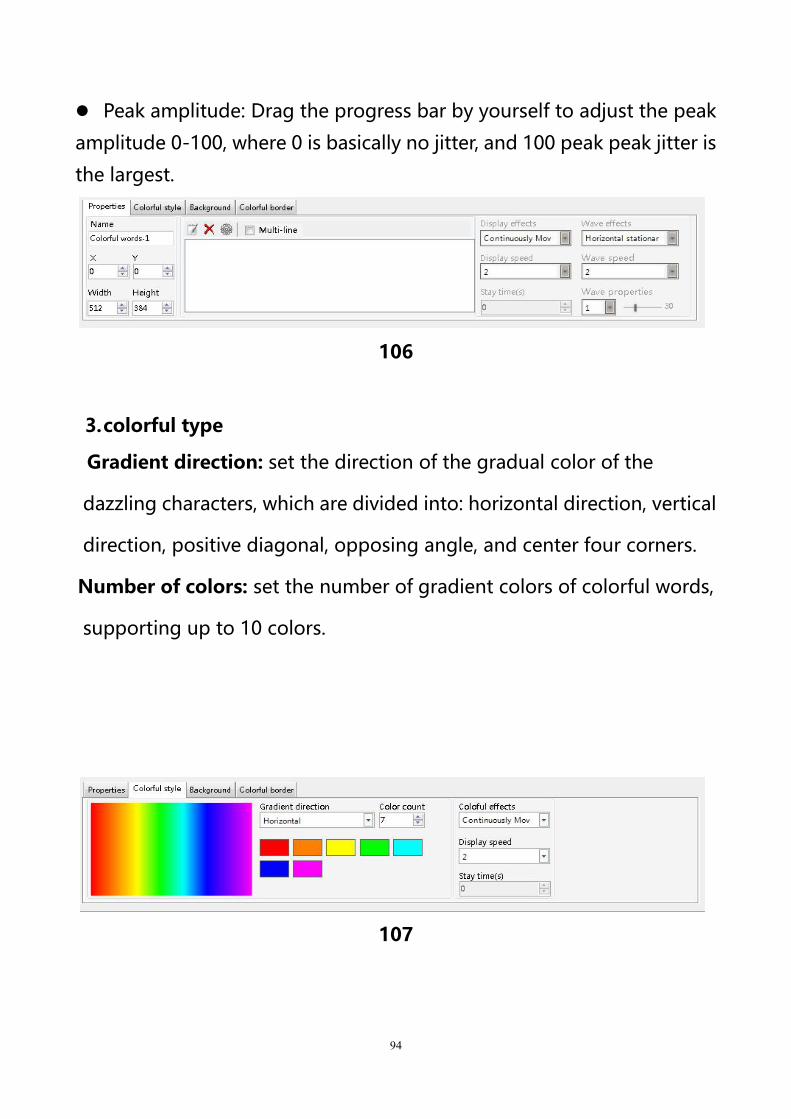
Display special effects: The special effects are randomly displayed
by default, and the specified special effects are displayed after selection.
The special effects are: quick play, static display,Special effects such as
moving up, moving down, moving left, moving right, etc.
Operation speed: Admission stunt operation speed is 1-16 level, of
which level 1 is the fastest.
Staying time: The staying time of the entry stunt is 1-128 seconds, of
which the staying time of 1 second is the shortest.
Wave stunt: wave stunt can choose none, horizontal static wave,
horizontal moving wave.
Fluctuation speed: Fluctuation speed is 1-16 level, of which the speed
of level 1 is the fastest.
Peak attributes: There are 1-5 peaks, of which 5 peaks are the most.
94
Peak amplitude: Drag the progress bar by yourself to adjust the peak
amplitude 0-100, where 0 is basically no jitter, and 100 peak peak jitter is
the largest.
106
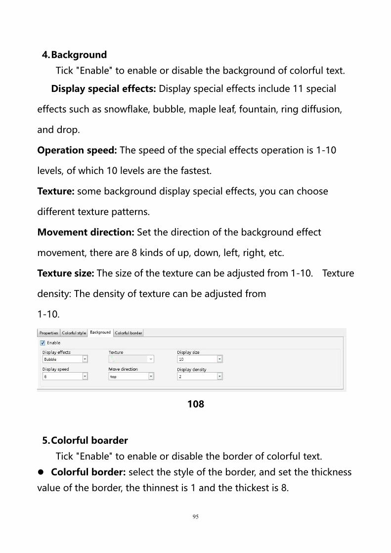
3.colorful type
Gradient direction: set the direction of the gradual color of the
dazzling characters, which are divided into: horizontal direction, vertical
direction, positive diagonal, opposing angle, and center four corners.
Number of colors: set the number of gradient colors of colorful words,
supporting up to 10 colors.
107
95
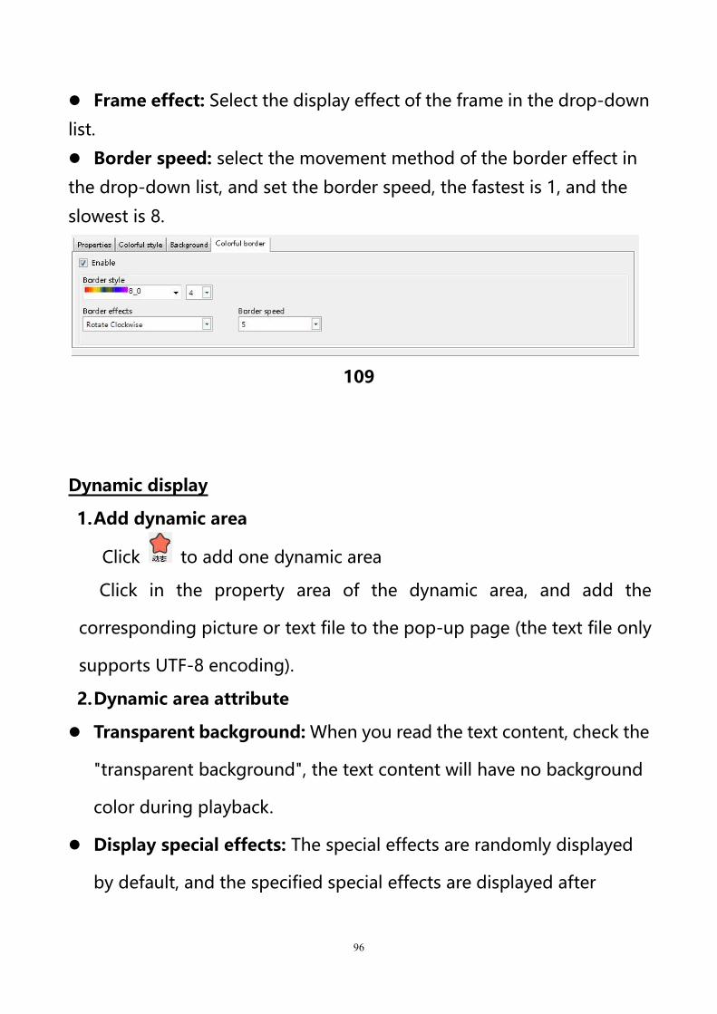
4.Background
Tick "Enable" to enable or disable the background of colorful text.
Display special effects: Display special effects include 11 special
effects such as snowflake, bubble, maple leaf, fountain, ring diffusion,
and drop.
Operation speed: The speed of the special effects operation is 1-10
levels, of which 10 levels are the fastest.
Texture: some background display special effects, you can choose
different texture patterns.
Movement direction: Set the direction of the background effect
movement, there are 8 kinds of up, down, left, right, etc.
Texture size: The size of the texture can be adjusted from 1-10. Texture
density: The density of texture can be adjusted from
1-10.
108
5.Colorful boarder
Tick "Enable" to enable or disable the border of colorful text.
Colorful border: select the style of the border, and set the thickness
value of the border, the thinnest is 1 and the thickest is 8.
96
Frame effect: Select the display effect of the frame in the drop-down
list.
Border speed: select the movement method of the border effect in
the drop-down list, and set the border speed, the fastest is 1, and the
slowest is 8.
109
Dynamic display
1.Add dynamic area
Click to add one dynamic area
Click in the property area of the dynamic area, and add the
corresponding picture or text file to the pop-up page (the text file only
supports UTF-8 encoding).
2.Dynamic area attribute
Transparent background: When you read the text content, check the
"transparent background", the text content will have no background
color during playback.
Display special effects: The special effects are randomly displayed
by default, and the specified special effects are displayed after
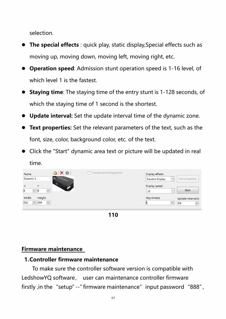
97
selection.
The special effects : quick play, static display,Special effects such as
moving up, moving down, moving left, moving right, etc.
Operation speed: Admission stunt operation speed is 1-16 level, of
which level 1 is the fastest.
Staying time: The staying time of the entry stunt is 1-128 seconds, of
which the staying time of 1 second is the shortest.
Update interval: Set the update interval time of the dynamic zone.
Text properties: Set the relevant parameters of the text, such as the
font, size, color, background color, etc. of the text.
Click the "Start" dynamic area text or picture will be updated in real
time.
110
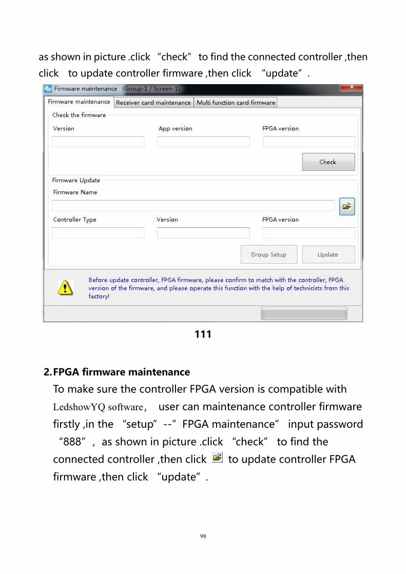
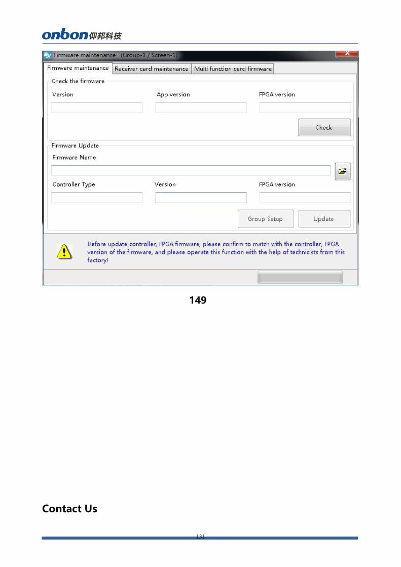
Firmware maintenance
1.Controller firmware maintenance
To make sure the controller software version is compatible with
LedshowYQ software, user can maintenance controller firmware
firstly ,in the“setup”--”firmware maintenance”input password“888”,
98
as shown in picture .click “check” to find the connected controller ,then
click to update controller firmware ,then click “update”.
111
2.FPGA firmware maintenance
To make sure the controller FPGA version is compatible with
LedshowYQ software, user can maintenance controller firmware
firstly ,in the “setup”--”FPGA maintenance” input password
“888”,as shown in picture .click “check” to find the
connected controller ,then click to update controller FPGA
firmware ,then click “update”.
99
112
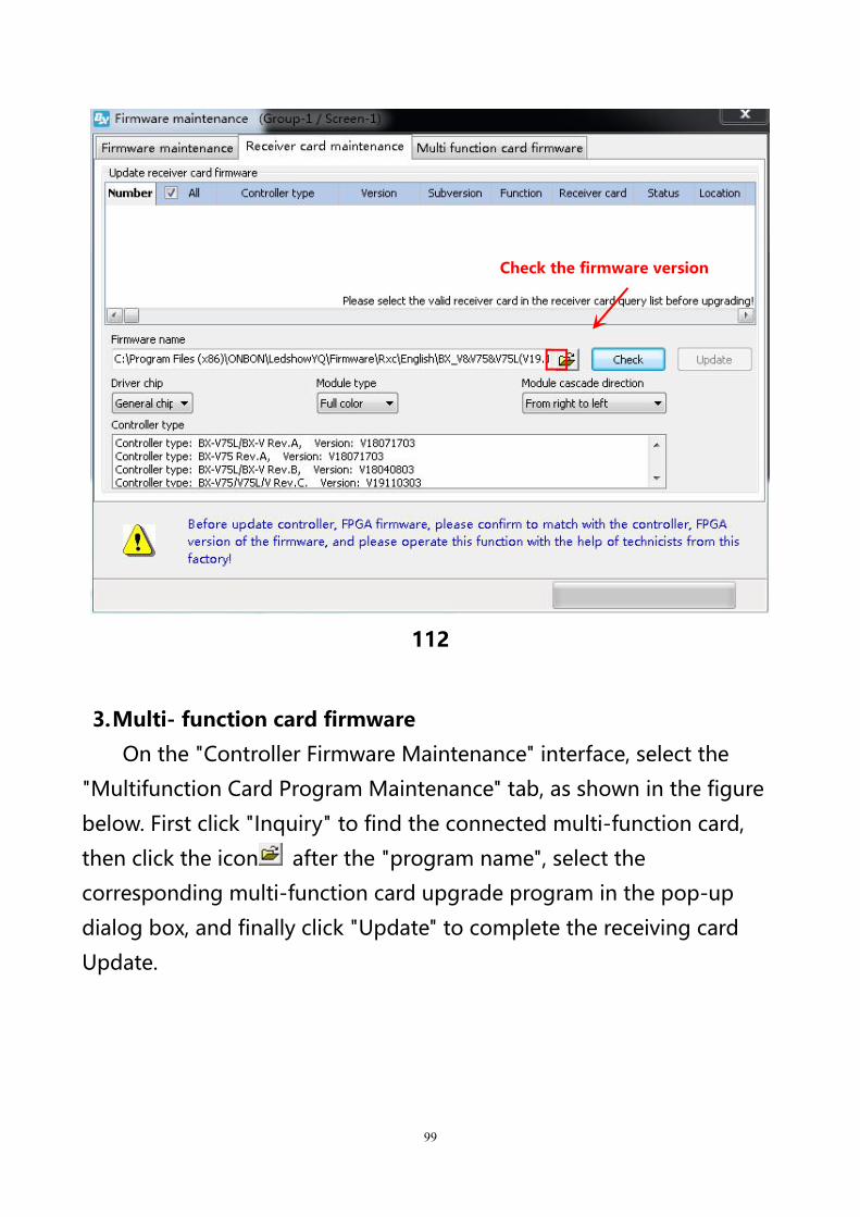
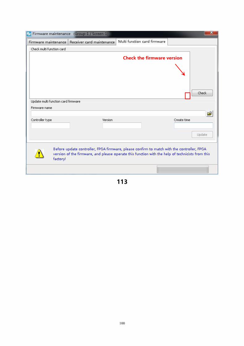
3.Multi- function card firmware
On the "Controller Firmware Maintenance" interface, select the
"Multifunction Card Program Maintenance" tab, as shown in the figure
below. First click "Inquiry" to find the connected multi-function card,
then click the icon after the "program name", select the
corresponding multi-function card upgrade program in the pop-up
dialog box, and finally click "Update" to complete the receiving card
Update.
Check the firmware version
100
113
Check the firmware version
101
Common functions
Time correction
Click ,or user can use the “common”menu and
select”correction time”to correct time for the controller time
and chip .
Brightness
102
Click ,user also can use the”common”in the menu to
select”brightness”function
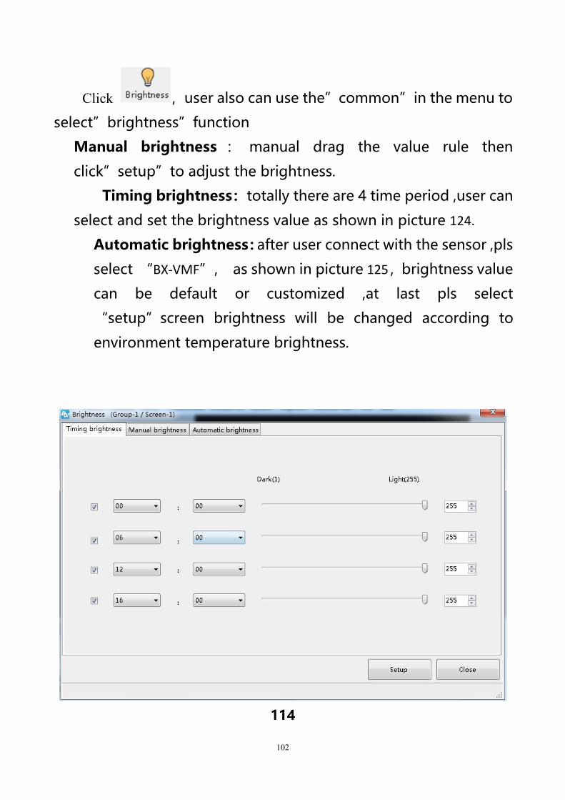
Manual brightness : manual drag the value rule then
click”setup”to adjust the brightness.
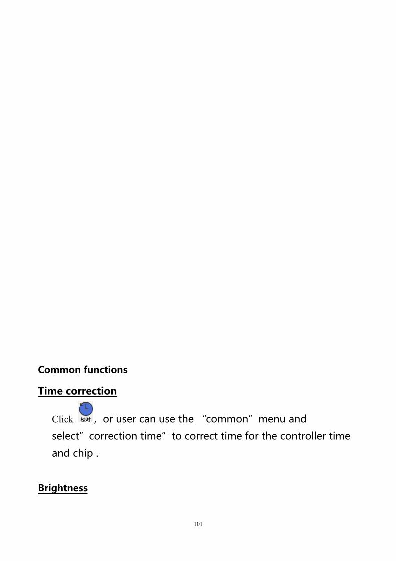
Timing brightness:totally there are 4 time period ,user can
select and set the brightness value as shown in picture 124.
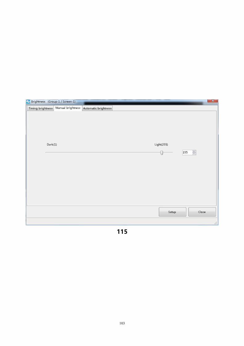
Automatic brightness:after user connect with the sensor ,pls
select “BX-VMF”, as shown in picture 125,brightness value
can be default or customized ,at last pls select
“setup”screen brightness will be changed according to
environment temperature brightness.
114
103
115
104
116
Volume
Click or user can change the volume from the menu--”common”--”volume”
Turn on
User can use the common--”turn on” to start the screen.
Turn off
User can use the common--”turn off” to close the screen.
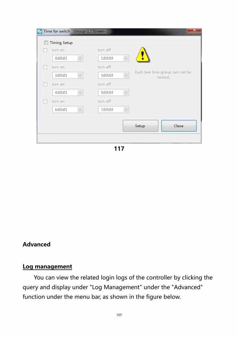
Timer for switch
User can use the “common” function--”timer for switch”to
set the turn on&off time ,as shown in picture.
105
117
Advanced
Log management
You can view the related login logs of the controller by clicking the
query and display under "Log Management" under the "Advanced"
function under the menu bar, as shown in the figure below.

106
118
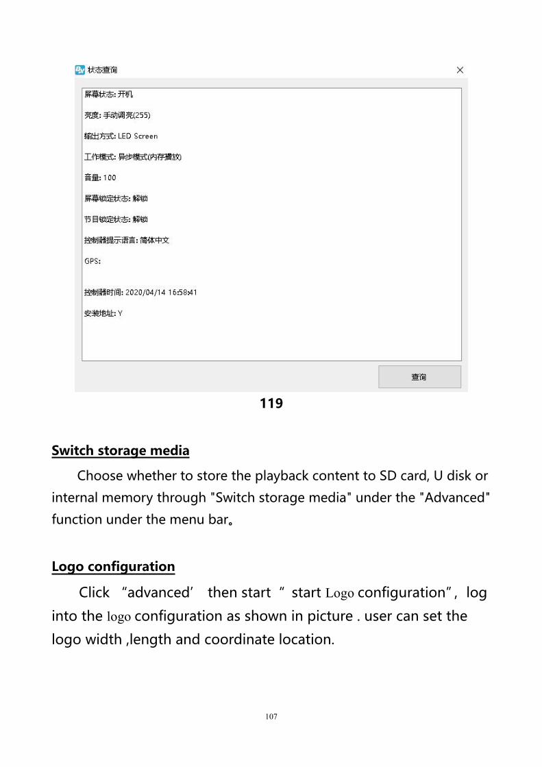
Advanced
You can check the working status of the controller through "Status
Inquiry" under the "Advanced" function under the menu bar, as shown in
the figure below.
107
119
Switch storage media
Choose whether to store the playback content to SD card, U disk or
internal memory through "Switch storage media" under the "Advanced"
function under the menu bar。
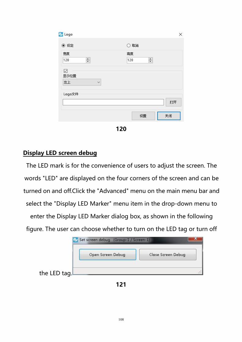
Logo configuration
Click “advanced’ then start“ start Logo configuration”,log
into the logo configuration as shown in picture . user can set the
logo width ,length and coordinate location.
108
120
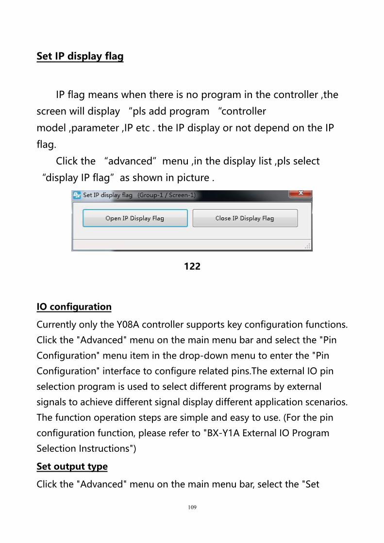
Display LED screen debug
The LED mark is for the convenience of users to adjust the screen. The
words "LED" are displayed on the four corners of the screen and can be
turned on and off.Click the "Advanced" menu on the main menu bar and
select the "Display LED Marker" menu item in the drop-down menu to
enter the Display LED Marker dialog box, as shown in the following
figure. The user can choose whether to turn on the LED tag or turn off
the LED tag.
121
109
Set IP display flag
IP flag means when there is no program in the controller ,the
screen will display “pls add program “controller
model ,parameter ,IP etc . the IP display or not depend on the IP
flag.
Click the “advanced”menu ,in the display list ,pls select
“display IP flag”as shown in picture .
122
IO configuration
Currently only the Y08A controller supports key configuration functions.
Click the "Advanced" menu on the main menu bar and select the "Pin
Configuration" menu item in the drop-down menu to enter the "Pin
Configuration" interface to configure related pins.The external IO pin
selection program is used to select different programs by external
signals to achieve different signal display different application scenarios.
The function operation steps are simple and easy to use. (For the pin
configuration function, please refer to "BX-Y1A External IO Program
Selection Instructions")
Set output type
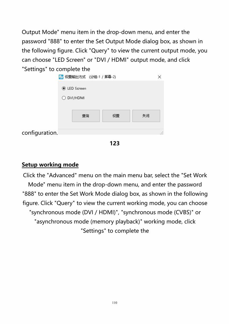
Click the "Advanced" menu on the main menu bar, select the "Set
110
Output Mode" menu item in the drop-down menu, and enter the
password "888" to enter the Set Output Mode dialog box, as shown in
the following figure. Click "Query" to view the current output mode, you
can choose "LED Screen" or "DVI / HDMI" output mode, and click
"Settings" to complete the
configuration.
123
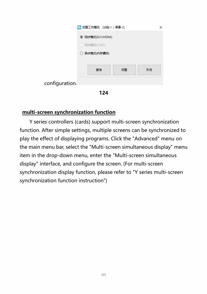
Setup working mode
Click the "Advanced" menu on the main menu bar, select the "Set Work
Mode" menu item in the drop-down menu, and enter the password
"888" to enter the Set Work Mode dialog box, as shown in the following
figure. Click "Query" to view the current working mode, you can choose
"synchronous mode (DVI / HDMI)", "synchronous mode (CVBS)" or
"asynchronous mode (memory playback)" working mode, click
"Settings" to complete the
111
configuration.
124
multi-screen synchronization function
Y series controllers (cards) support multi-screen synchronization
function. After simple settings, multiple screens can be synchronized to
play the effect of displaying programs. Click the "Advanced" menu on
the main menu bar, select the "Multi-screen simultaneous display" menu
item in the drop-down menu, enter the "Multi-screen simultaneous
display" interface, and configure the screen. (For multi-screen
synchronization display function, please refer to "Y series multi-screen
synchronization function instruction")
112
125
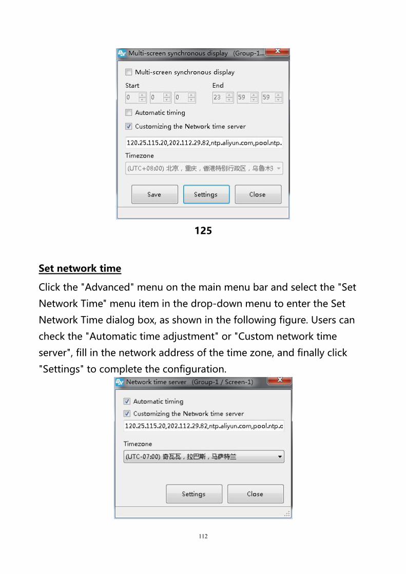
Set network time
Click the "Advanced" menu on the main menu bar and select the "Set
Network Time" menu item in the drop-down menu to enter the Set
Network Time dialog box, as shown in the following figure. Users can
check the "Automatic time adjustment" or "Custom network time
server", fill in the network address of the time zone, and finally click
"Settings" to complete the configuration.
113
126
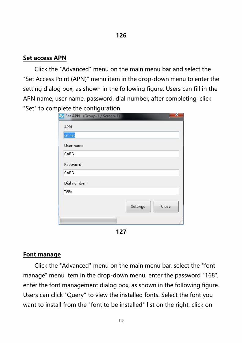
Set access APN
Click the "Advanced" menu on the main menu bar and select the
"Set Access Point (APN)" menu item in the drop-down menu to enter the
setting dialog box, as shown in the following figure. Users can fill in the
APN name, user name, password, dial number, after completing, click
"Set" to complete the configuration.
127
Font manage
Click the "Advanced" menu on the main menu bar, select the "font
manage" menu item in the drop-down menu, enter the password "168",
enter the font management dialog box, as shown in the following figure.
Users can click "Query" to view the installed fonts. Select the font you
want to install from the "font to be installed" list on the right, click on
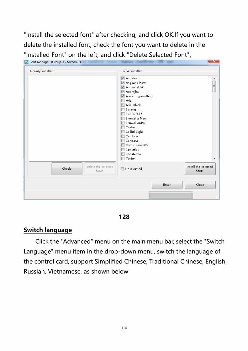
114
"Install the selected font" after checking, and click OK.If you want to
delete the installed font, check the font you want to delete in the
"Installed Font" on the left, and click "Delete Selected Font"。
128
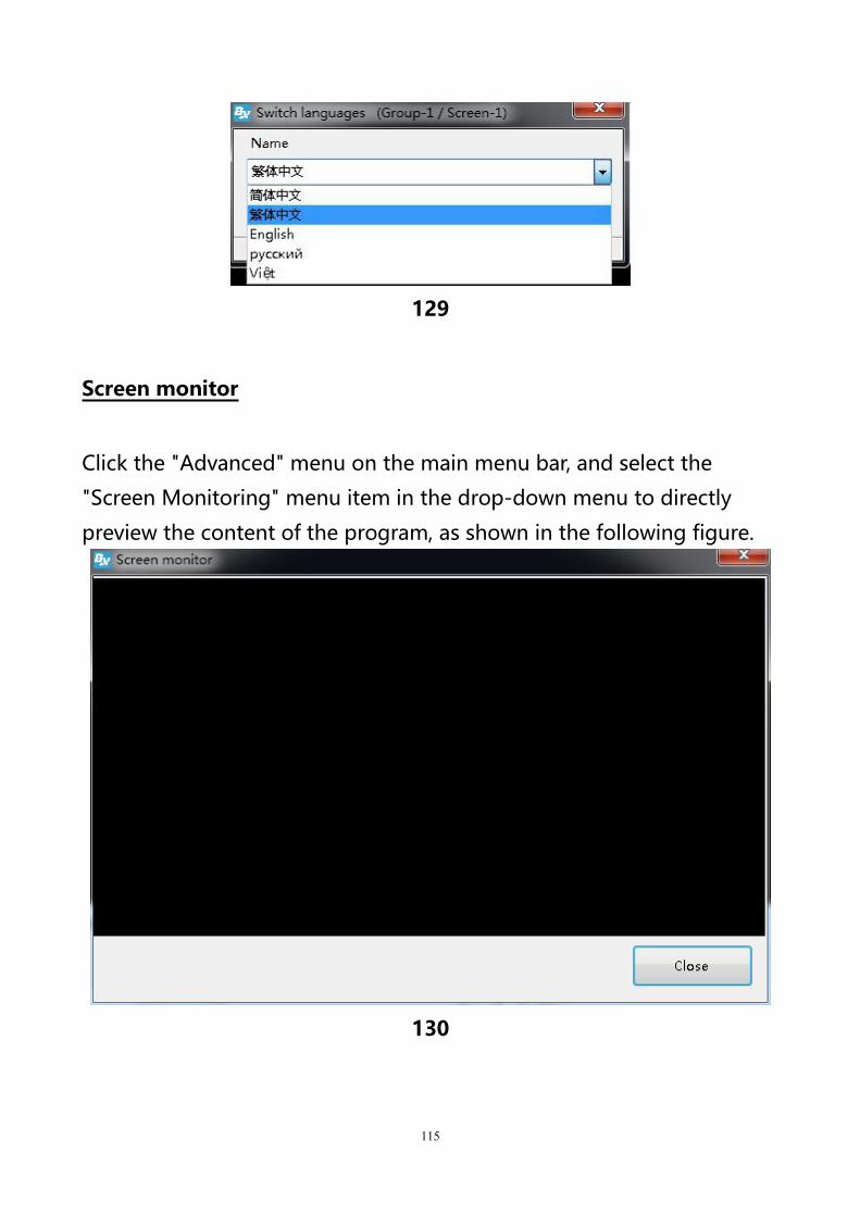
Switch language
Click the "Advanced" menu on the main menu bar, select the "Switch
Language" menu item in the drop-down menu, switch the language of
the control card, support Simplified Chinese, Traditional Chinese, English,
Russian, Vietnamese, as shown below
115
129
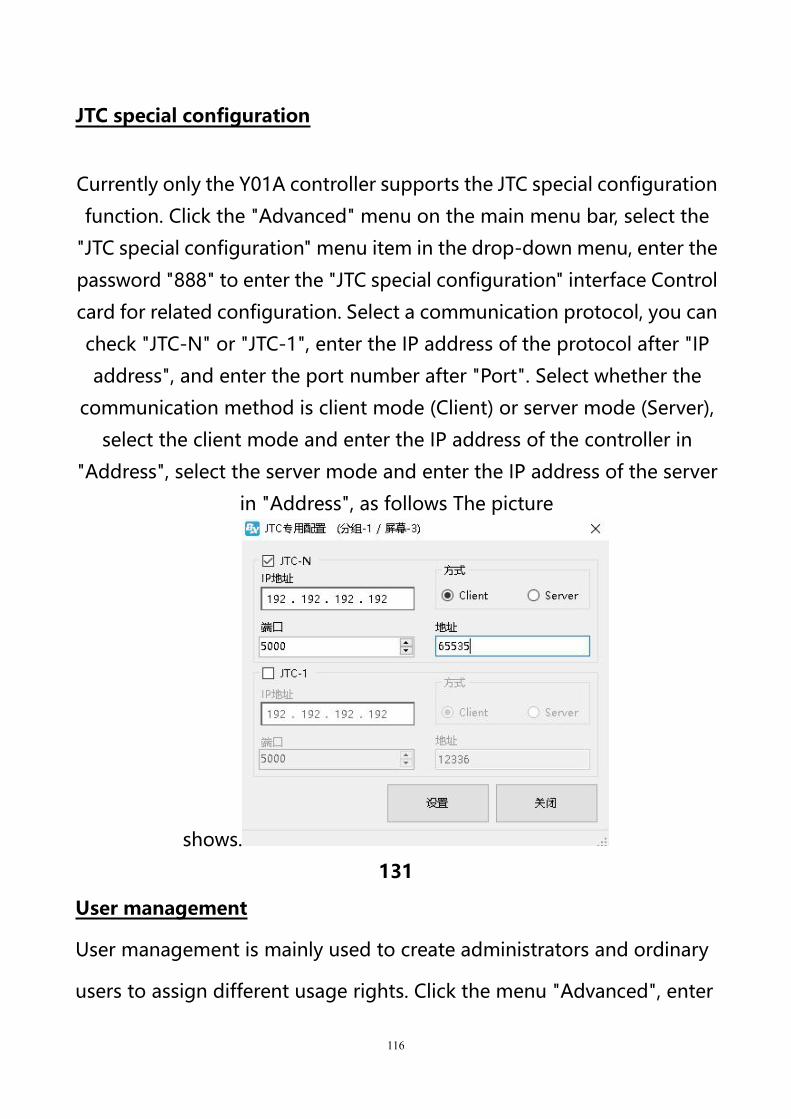
Screen monitor
Click the "Advanced" menu on the main menu bar, and select the
"Screen Monitoring" menu item in the drop-down menu to directly
preview the content of the program, as shown in the following figure.
130
116
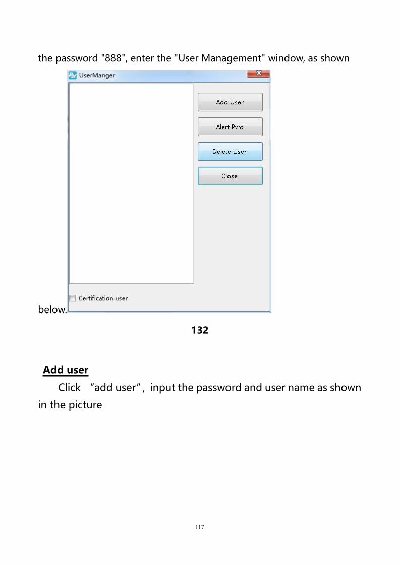
JTC special configuration
Currently only the Y01A controller supports the JTC special configuration
function. Click the "Advanced" menu on the main menu bar, select the
"JTC special configuration" menu item in the drop-down menu, enter the
password "888" to enter the "JTC special configuration" interface Control
card for related configuration. Select a communication protocol, you can
check "JTC-N" or "JTC-1", enter the IP address of the protocol after "IP
address", and enter the port number after "Port". Select whether the
communication method is client mode (Client) or server mode (Server),
select the client mode and enter the IP address of the controller in
"Address", select the server mode and enter the IP address of the server
in "Address", as follows The picture
shows.
131
User management
User management is mainly used to create administrators and ordinary
users to assign different usage rights. Click the menu "Advanced", enter
117
the password "888", enter the "User Management" window, as shown
below.
132
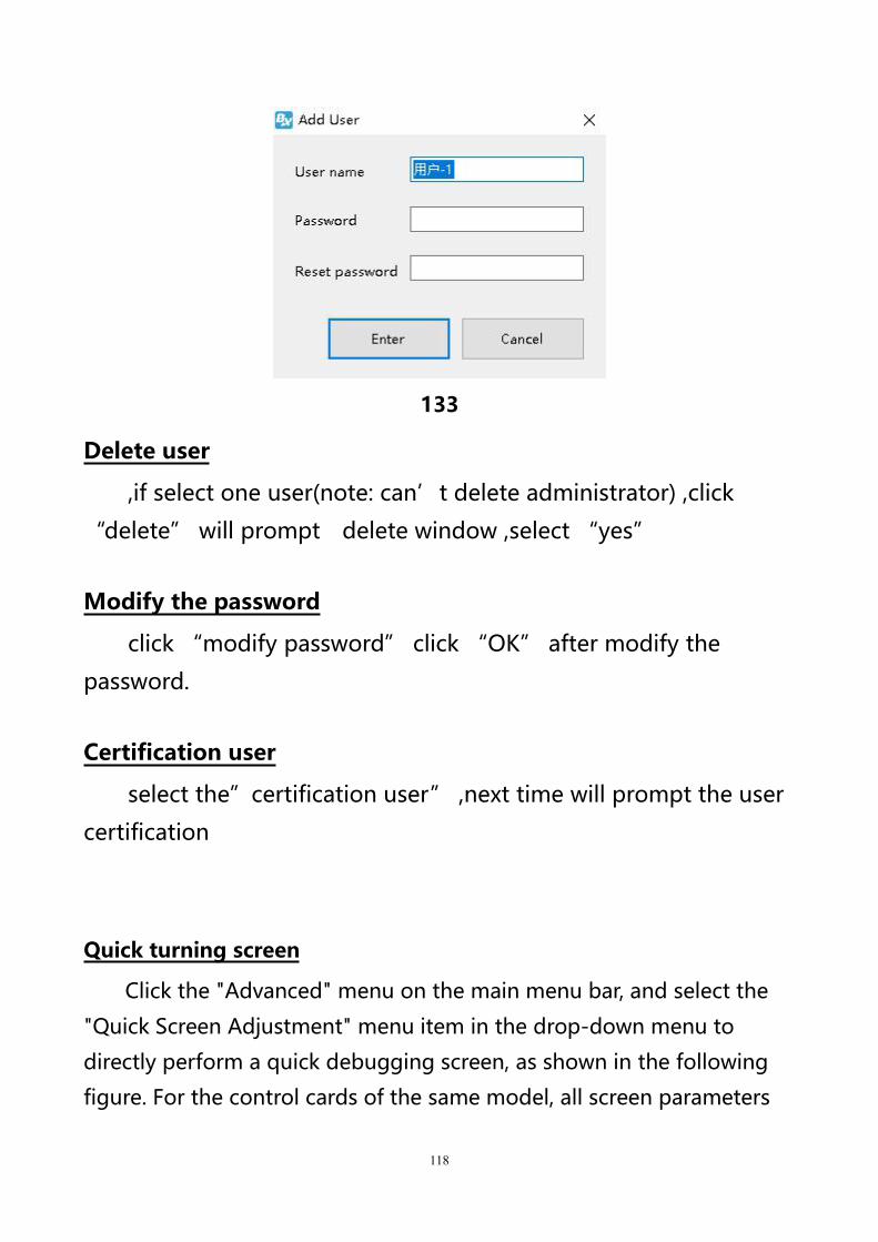
Add user
Click “add user”,input the password and user name as shown
in the picture
118
133
Delete user
,if select one user(note: can’t delete administrator) ,click
“delete” will prompt delete window ,select “yes”
Modify the password
click “modify password” click “OK” after modify the
password.
Certification user
select the”certification user” ,next time will prompt the user
certification
Quick turning screen
Click the "Advanced" menu on the main menu bar, and select the
"Quick Screen Adjustment" menu item in the drop-down menu to
directly perform a quick debugging screen, as shown in the following
figure. For the control cards of the same model, all screen parameters
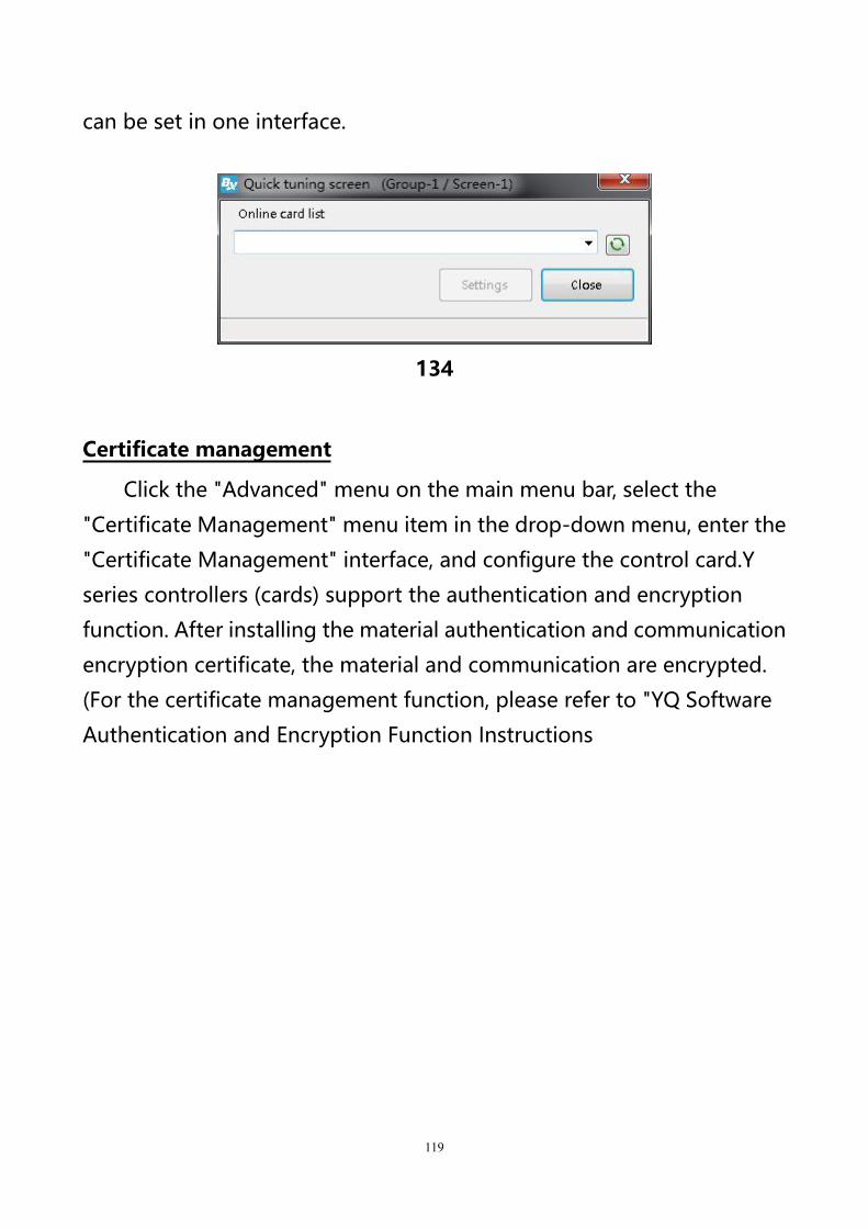
119
can be set in one interface.
134
Certificate management
Click the "Advanced" menu on the main menu bar, select the
"Certificate Management" menu item in the drop-down menu, enter the
"Certificate Management" interface, and configure the control card.Y
series controllers (cards) support the authentication and encryption
function. After installing the material authentication and communication
encryption certificate, the material and communication are encrypted.
(For the certificate management function, please refer to "YQ Software
Authentication and Encryption Function Instructions
120
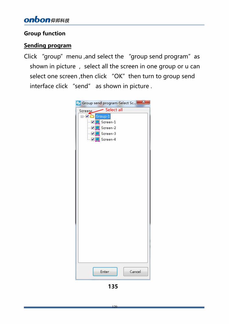
Group function
Sending program
Click “group”menu ,and select the “group send program”as
shown in picture ,select all the screen in one group or u can
select one screen ,then click “OK”then turn to group send
interface click “send” as shown in picture .
135
Select all
121
136
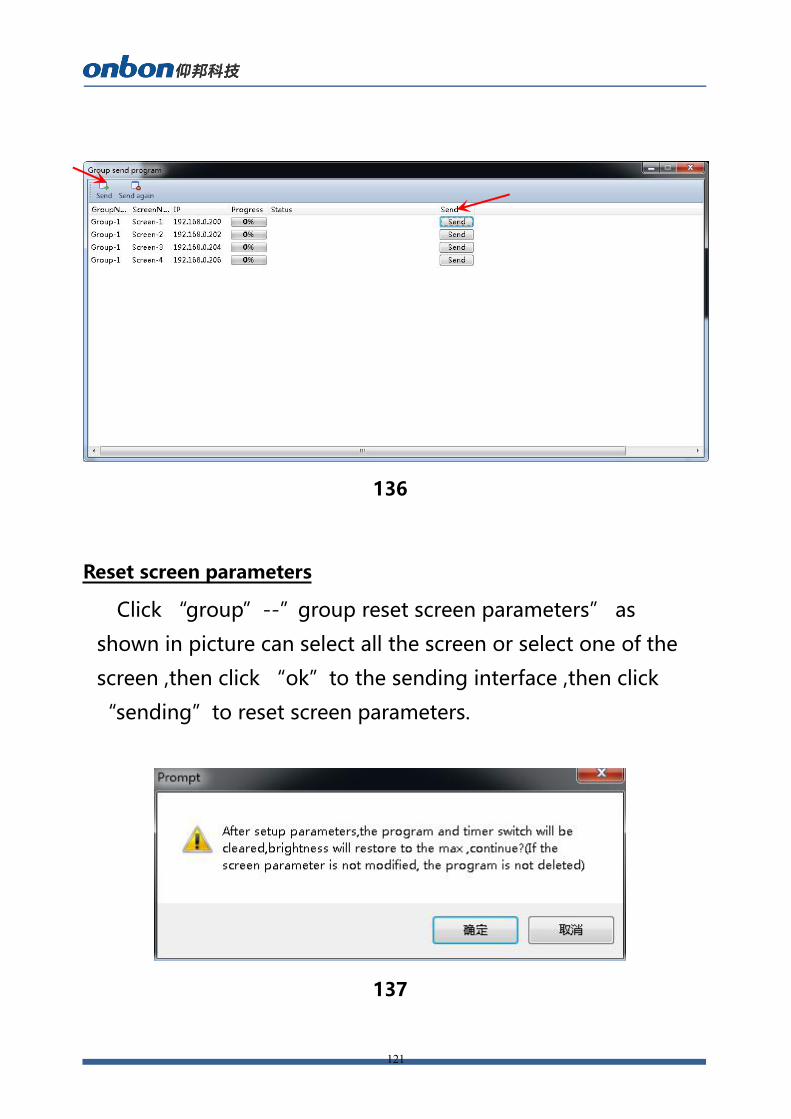
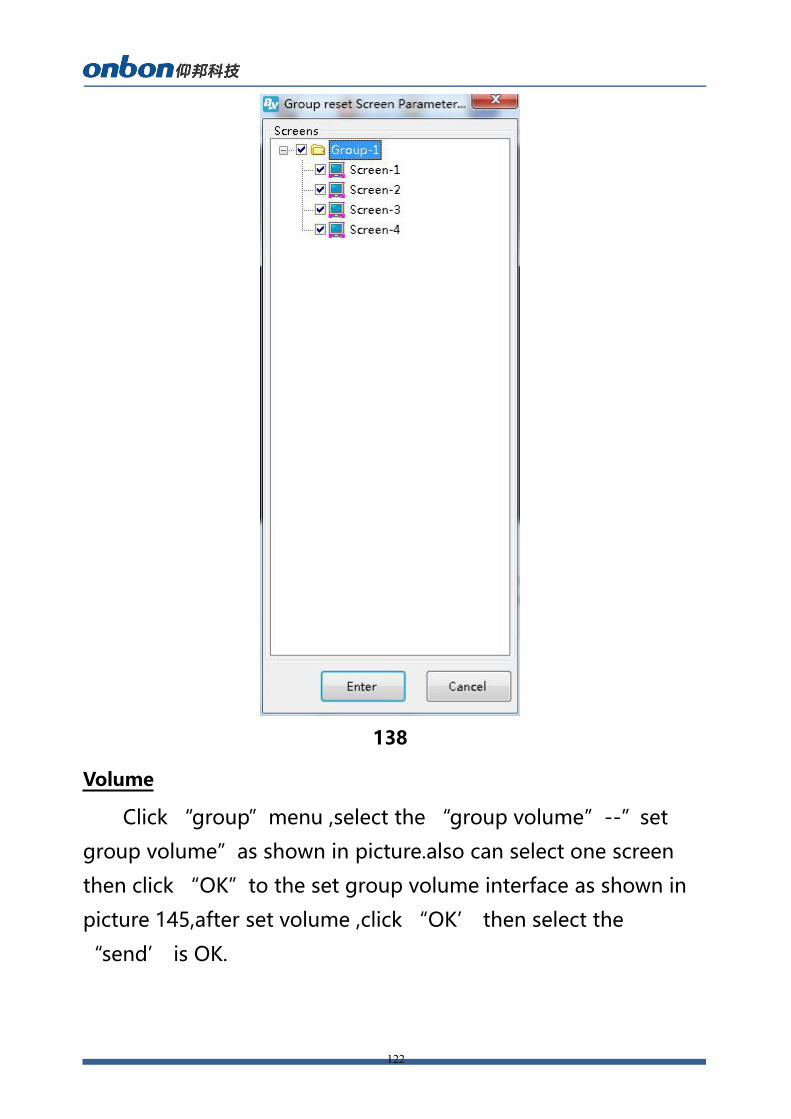
Reset screen parameters
Click “group”--”group reset screen parameters” as
shown in picture can select all the screen or select one of the
screen ,then click “ok”to the sending interface ,then click
“sending”to reset screen parameters.
137
122
138
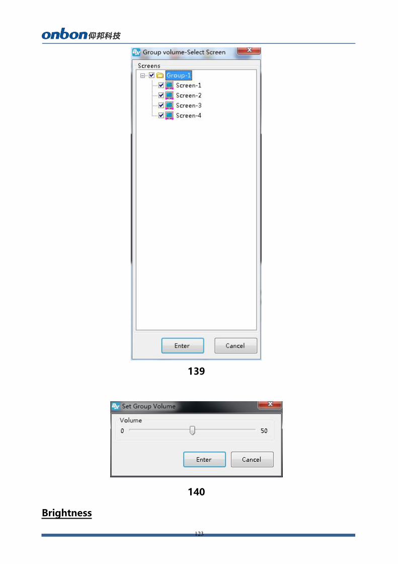
Volume
Click “group”menu ,select the “group volume”--”set
group volume”as shown in picture.also can select one screen
then click “OK”to the set group volume interface as shown in
picture 145,after set volume ,click “OK’ then select the
“send’ is OK.
123
139
140
Brightness
124
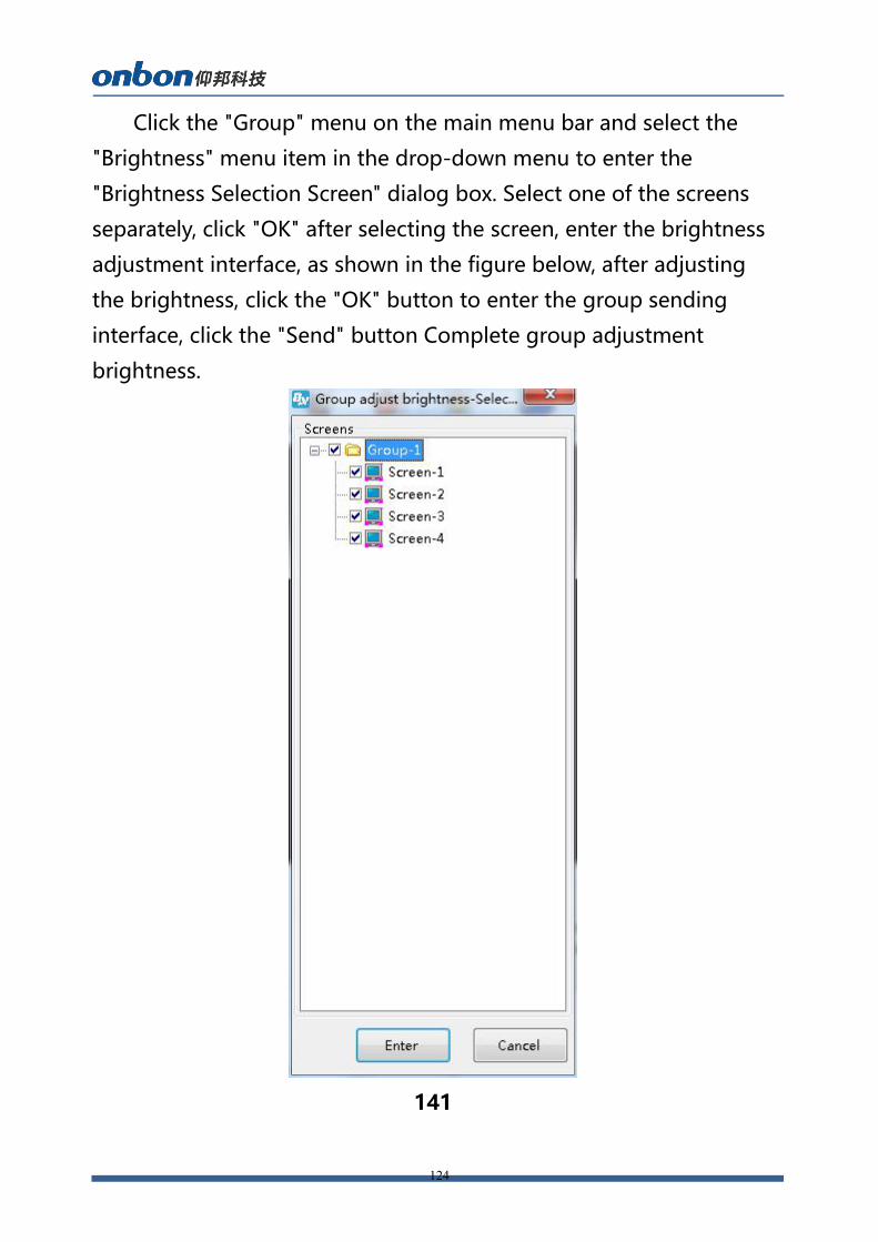
Click the "Group" menu on the main menu bar and select the
"Brightness" menu item in the drop-down menu to enter the
"Brightness Selection Screen" dialog box. Select one of the screens
separately, click "OK" after selecting the screen, enter the brightness
adjustment interface, as shown in the figure below, after adjusting
the brightness, click the "OK" button to enter the group sending
interface, click the "Send" button Complete group adjustment
brightness.
141

125
142
Correction time
Click the "Group" menu on the main menu bar, select the "School
Time" menu item in the drop-down menu, and enter the "School
Time Selection Screen" dialog box, as shown in the following figure,
you can select all the screens under a group, You can also select one
of the screens separately. After selecting the screen, click "OK" to
enter the group sending interface. After clicking the "Send" button,
you can complete the group timing.
126
143
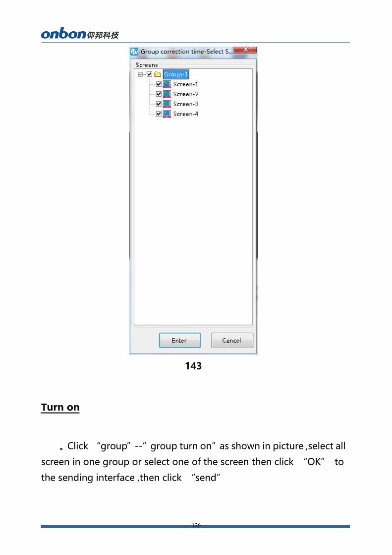
Turn on
。Click “group”--”group turn on”as shown in picture ,select all
screen in one group or select one of the screen then click “OK” to
the sending interface ,then click “send”
127
144
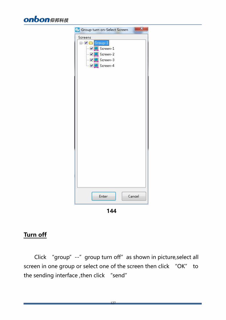
Turn off
Click “group”--”group turn off”as shown in picture,select all
screen in one group or select one of the screen then click “OK” to
the sending interface ,then click “send”
128
145
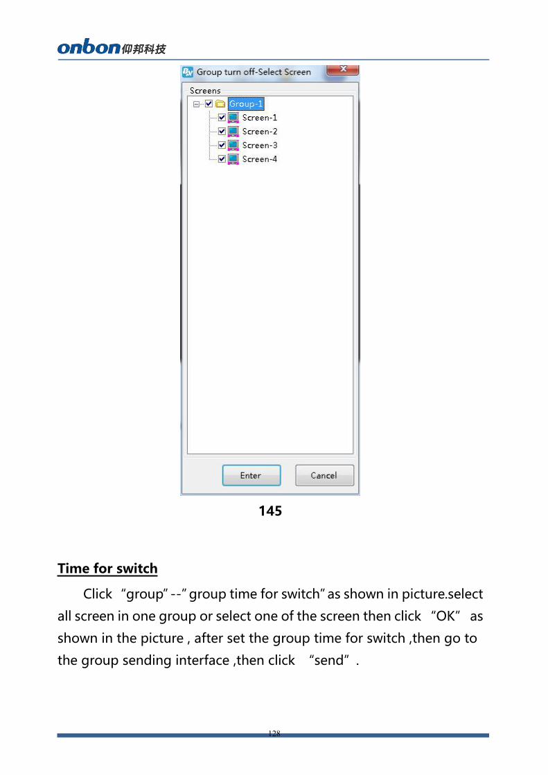
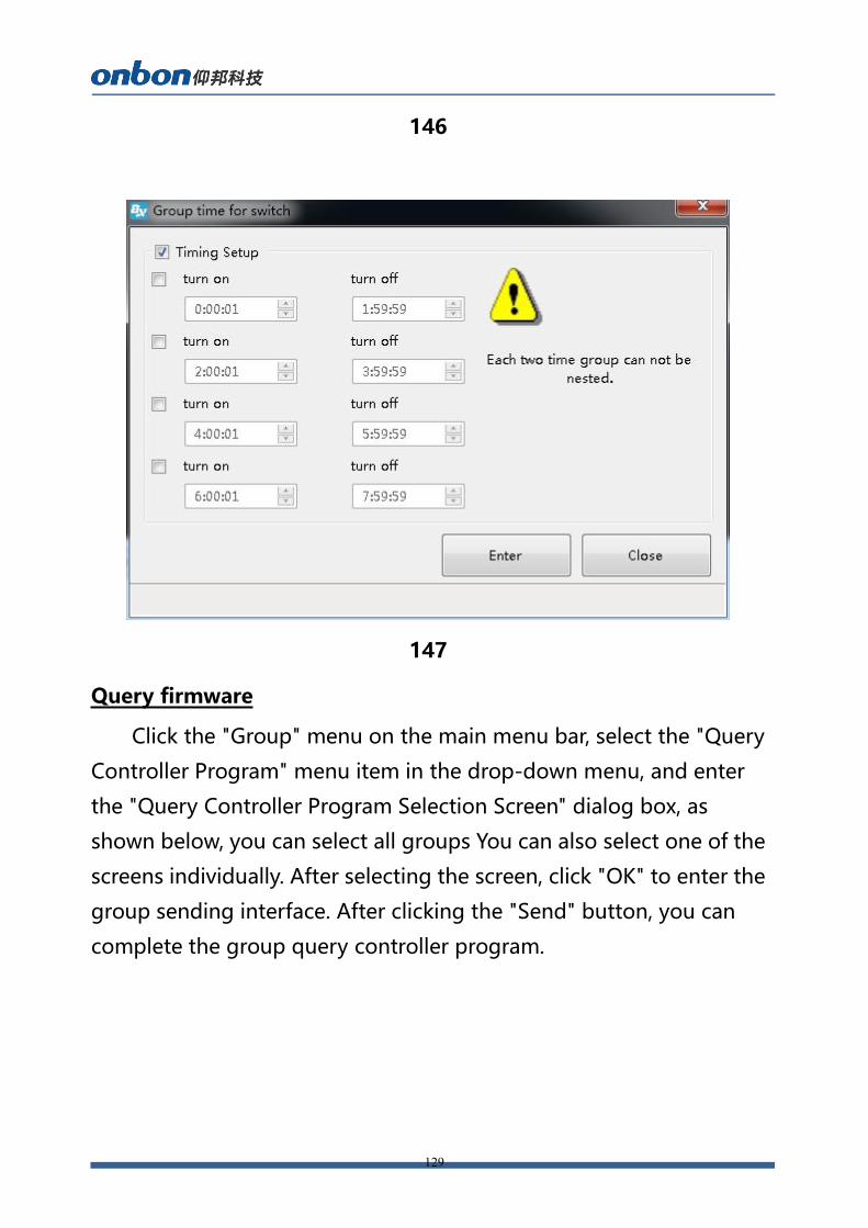
Time for switch
Click“group”--”group time for switch”as shown in picture.select
all screen in one group or select one of the screen then click “OK” as
shown in the picture , after set the group time for switch ,then go to
the group sending interface ,then click “send”.
129
146
147
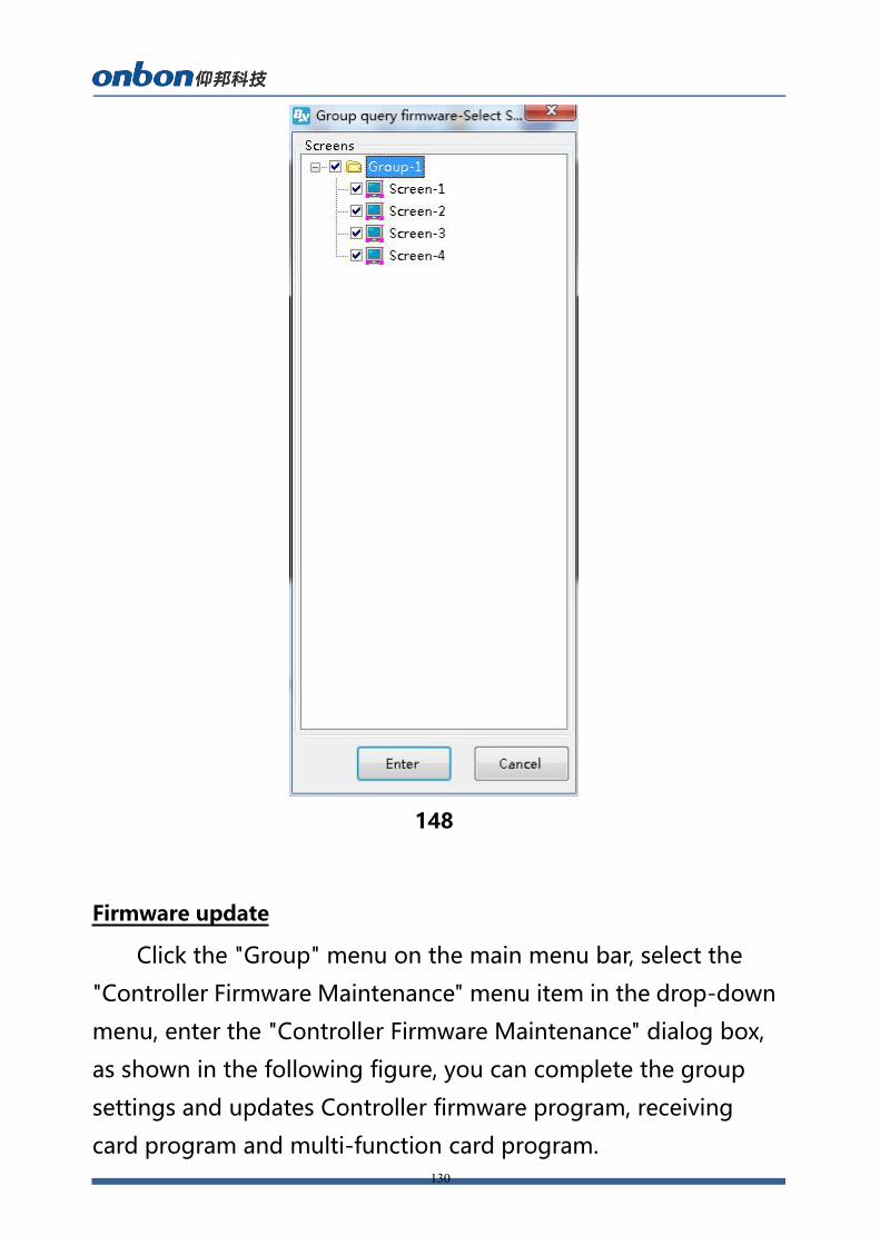
Query firmware
Click the "Group" menu on the main menu bar, select the "Query
Controller Program" menu item in the drop-down menu, and enter
the "Query Controller Program Selection Screen" dialog box, as
shown below, you can select all groups You can also select one of the
screens individually. After selecting the screen, click "OK" to enter the
group sending interface. After clicking the "Send" button, you can
complete the group query controller program.
130
148
Firmware update
Click the "Group" menu on the main menu bar, select the
"Controller Firmware Maintenance" menu item in the drop-down
menu, enter the "Controller Firmware Maintenance" dialog box,
as shown in the following figure, you can complete the group
settings and updates Controller firmware program, receiving
card program and multi-function card program.
131
149
Contact Us

132
Shanghai ONBON Technology Inc. (Headquarters)Address: 7 Floor, Tower 88, 1199#, North Qinzhou Road, Xuhui
District, Shanghai City, China
Tel Phone: 086-21-64955136
Fax: 086-21-64955136
Website: www.onbonbx.com
ONBON (Jiangsu) Optoelectronic Industrial Co.,LTDAddress: 1299#, Fuchun Jiang Road, Kunshan City, Jiangsu Province,
China
Sales ContactsTel: 0086-15921814956 0086-15800379719
Email: [email protected]
Second DevelopmentTel: 0512-66589212
Email: [email protected]
iLEDCloudWebsite: http://www.iledcloud.com/
Public Wechat ONBON APP


![=yq;fd; vau;iyd;];; Mz;lwpf;if - SriLankan Airlines · Mz;lwpf;if 2018/19 vau;yapd; nrd;lu;> gz;lhuehaf ,d;lu;Ne~dy; Vu;Nghu;l;> fl;Lehaf> = yq;fh. =yq;fd; vau;iyd;];; | Mz;lwpf;if](https://img.pdfslide.net/doc/110x75/5e41145176a731229774b840/yqfd-vauiyd-mzlwpfif-srilankan-airlines-mzlwpfif-201819-vauyapd.jpg)


![Waterfront Lot: YQ N0 Comer Lot: Y@N[] Deed Title](https://img.pdfslide.net/doc/110x75/6172f96de3cc3029c5035ec6/waterfront-lot-yq-n0-comer-lot-yn-deed-title-.jpg)