Embed Size (px)
Citation preview
www.ScanGauge.com
Version 1.0
User ManualPlugs into the J1939 or J1708 diagnostic connector already built into most 1987 or Newer Diesel Pusher Motor Homes,
RV’s and Large Diesel Over-The-Road Trucks
WARNINGUse of the ScanGauge while driving could lead to an accident and serious injuries. The primary attention of the driver should always be on safe driving. As with any gauge or other instrumentation system in a motor vehicle, the information should be observed as part of a normal sequence of observations performed in the operation of the vehicle. Changes to the selections in the ScanGauge should only be made when it is safe to do so. The driver must remain attentive to driving the vehicle.
The mounting of the ScanGauge and the routing of the cable connecting it to the vehicle should be done with suitable caution so it does not create an unsafe condition. This includes but is not limited to the following restrictions:
• Do Not mount the ScanGauge where it can obstruct the view of the driver.
• Do Not mount the ScanGauge in a manner that could cause it to be propelled through the vehicle during an accident causing injury, such as over or near an air bag.
• Do Not route the cable in a manner that would interfere with the operation of the vehicle controls.
RIGHTS AND OBLIGATIONSThe ScanGauge may be used on any number of vehicles. The software contained in the ScanGauge is copyright protected by Linear Logic and may not be transferred or disassembled and used in another product, in part or in whole. The artwork used in generation of the circuitry is also copyright protected and cannot be used in part or in whole by any person or entity without the express written permission of Linear Logic.
© 2004-2012 by Linear Logic. All rights reserved.
2 — www.ScanGauge.com
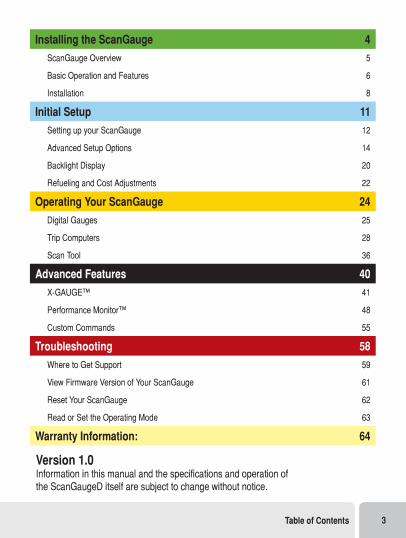
Version 1.0 Information in this manual and the specifications and operation of the ScanGaugeD itself are subject to change without notice.
Installing the ScanGauge 4
ScanGauge Overview 5
Basic Operation and Features 6
Installation 8
Initial Setup 11
Setting up your ScanGauge 12
Advanced Setup Options 14
Backlight Display 20
Refueling and Cost Adjustments 22
Operating Your ScanGauge 24
Digital Gauges 25
Trip Computers 28
Scan Tool 36
Advanced Features 40
X-GAUGE™ 41
Performance Monitor™ 48
Custom Commands 55
Troubleshooting 58
Where to Get Support 59
View Firmware Version of Your ScanGauge 61
Reset Your ScanGauge 62
Read or Set the Operating Mode 63
Warranty Information: 64
Table of Contents 3

Installing the ScanGaugeThe ScanGauge is simple to install and requires no additional power source other than that provided by the diagnostic connector.
There are, however, some important considerations when choosing a location for your ScanGauge. Please see the Installation section for detailed information.
ScanGauge Overview 5
Basic Operation and Features 6
Locating the J1939/J1708 Connector 8
Mounting Your ScanGauge 8
Connecting Your ScanGauge 8
Important Installation Considerations 10
4 — www.ScanGauge.com
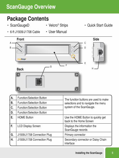
Package Contents• ScanGaugeD
• 6-ft J1939/J1708 Cable
• Velcro® Strips
• User Manual
• Quick Start Guide
ScanGauge Overview
A. Function/Selection Button The function buttons are used to make selections and to navigate the menu system of the ScanGauge.
B. Function/Selection Button
C. Function/Selection Button
D. Function/Selection Button
E. HOME Button Use the HOME Button to quickly get back to the Home Screen
F. LCD Display Screen Displays the information the ScanGauge records
G. J1939/J1708 Connection Plug Primary connector
H. J1939/J1708 Connection Plug Secondary connector or Daisy Chain interface
Front Side
Back
A
B
C
D
E
HG F
Installing the ScanGauge 5
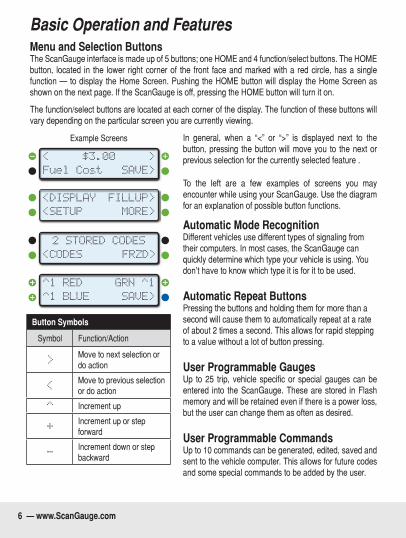
Basic Operation and Features Menu and Selection ButtonsThe ScanGauge interface is made up of 5 buttons; one HOME and 4 function/select buttons. The HOME button, located in the lower right corner of the front face and marked with a red circle, has a single function — to display the Home Screen. Pushing the HOME button will display the Home Screen as shown on the next page. If the ScanGauge is off, pressing the HOME button will turn it on.
The function/select buttons are located at each corner of the display. The function of these buttons will vary depending on the particular screen you are currently viewing.
In general, when a “<” or “>” is displayed next to the button, pressing the button will move you to the next or previous selection for the currently selected feature .
To the left are a few examples of screens you may encounter while using your ScanGauge. Use the diagram for an explanation of possible button functions.
Automatic Mode RecognitionDifferent vehicles use different types of signaling from their computers. In most cases, the ScanGauge can quickly determine which type your vehicle is using. You don’t have to know which type it is for it to be used.
Automatic Repeat ButtonsPressing the buttons and holding them for more than a second will cause them to automatically repeat at a rate of about 2 times a second. This allows for rapid stepping to a value without a lot of button pressing.
User Programmable GaugesUp to 25 trip, vehicle specific or special gauges can be entered into the ScanGauge. These are stored in Flash memory and will be retained even if there is a power loss, but the user can change them as often as desired.
User Programmable CommandsUp to 10 commands can be generated, edited, saved and sent to the vehicle computer. This allows for future codes and some special commands to be added by the user.
Button Symbols
Symbol Function/Action
>Move to next selection or do action
<Move to previous selection or do action
^ Increment up
+Increment up or step forward
-Increment down or step backward
Fuel Cost
<
SAVE>
>$3.00
<SETUP
<DISPLAY
MORE>
FILLUP>
2 STORED CODES
<CODES FRZD>
^1 BLUE
^1 RED
SAVE>
GRN ^1
Example Screens
6 — www.ScanGauge.com
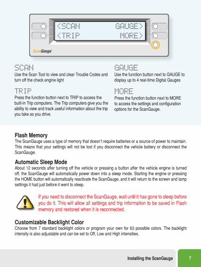
Flash MemoryThe ScanGauge uses a type of memory that doesn’t require batteries or a source of power to maintain. This means that your settings will not be lost if you disconnect the vehicle battery or disconnect the ScanGauge.
Automatic Sleep ModeAbout 12 seconds after turning off the vehicle or pressing a button after the vehicle engine is turned off, the ScanGauge will automatically power down into a sleep mode. Starting the engine or pressing the HOME button will automatically reactivate the ScanGauge, and it will return to the screen and lamp settings it had just before it went to sleep.
If you need to disconnect the ScanGauge, wait until it has gone to sleep before you do it. This will allow all settings and trip information to be saved in Flash memory and restored when it is reconnected.
Customizable Backlight ColorChoose from 7 standard backlight colors or program your own for 63 possible colors. The backlight intensity is also adjustable and can be set to Off, Low and High intensities.
<SCAN
<TRIP
GAUGE>
MORE>
SCAN Use the Scan Tool to view and clear Trouble Codes and turn off the check engine light
GAUGE Use the function button next to GAUGE to display up to 4 real-time Digital Gauges
TRIP Press the function button next to TRIP to access the built-in Trip computers. The Trip computers give you the ability to view and track useful information about the trip you take as you drive.
MORE Press the function button next to MORE to access the settings and configuration options for the ScanGauge.
Installing the ScanGauge 7
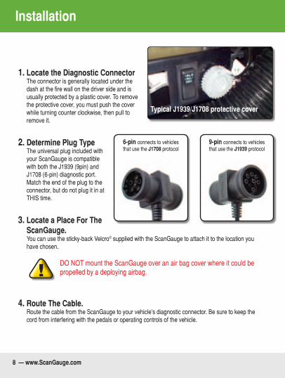
1. Locate the Diagnostic Connector The connector is generally located under the dash at the fire wall on the driver side and is usually protected by a plastic cover. To remove the protective cover, you must push the cover while turning counter clockwise, then pull to remove it.
2. Determine Plug Type The universal plug included with your ScanGauge is compatible with both the J1939 (9pin) and J1708 (6-pin) diagnostic port. Match the end of the plug to the connector, but do not plug it in at THIS time.
3. Locate a Place For The ScanGauge. You can use the sticky-back Velcro® supplied with the ScanGauge to attach it to the location you have chosen.
DO NOT mount the ScanGauge over an air bag cover where it could be propelled by a deploying airbag.
4. Route The Cable. Route the cable from the ScanGauge to your vehicle’s diagnostic connector. Be sure to keep the cord from interfering with the pedals or operating controls of the vehicle.
6-pin connects to vehicles that use the J1708 protocol
9-pin connects to vehicles that use the J1939 protocol
Installation
Typical J1939/J1708 protective cover
8 — www.ScanGauge.com
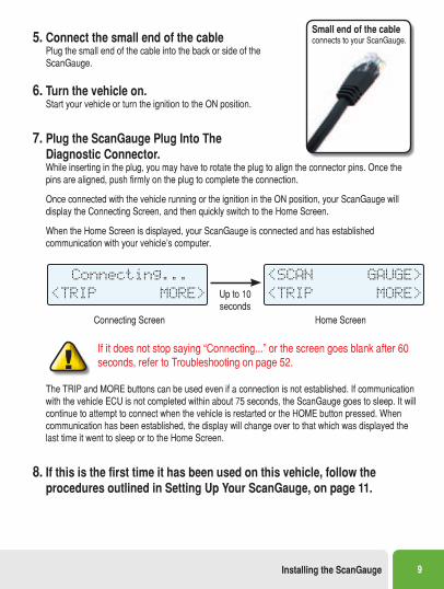
5. Connect the small end of the cable Plug the small end of the cable into the back or side of the ScanGauge.
6. Turn the vehicle on. Start your vehicle or turn the ignition to the ON position.
7. Plug the ScanGauge Plug Into The Diagnostic Connector. While inserting in the plug, you may have to rotate the plug to align the connector pins. Once the pins are aligned, push firmly on the plug to complete the connection. Once connected with the vehicle running or the ignition in the ON position, your ScanGauge will display the Connecting Screen, and then quickly switch to the Home Screen. When the Home Screen is displayed, your ScanGauge is connected and has established communication with your vehicle’s computer.
Connecting...
<TRIP MORE>
Connecting Screen
<SCAN
<TRIP
GAUGE>
MORE>
Home Screen
Up to 10 seconds
If it does not stop saying “Connecting...” or the screen goes blank after 60 seconds, refer to Troubleshooting on page 52.
The TRIP and MORE buttons can be used even if a connection is not established. If communication with the vehicle ECU is not completed within about 75 seconds, the ScanGauge goes to sleep. It will continue to attempt to connect when the vehicle is restarted or the HOME button pressed. When communication has been established, the display will change over to that which was displayed the last time it went to sleep or to the Home Screen.
8. If this is the first time it has been used on this vehicle, follow the procedures outlined in Setting Up Your ScanGauge, on page 11.
Small end of the cable connects to your ScanGauge.
Installing the ScanGauge 9
Important Installation ConsiderationsTheScanGaugehasanoperatingtemperaturerangeof0˚Fto160˚F(-18˚Cto71˚C).Athighertem-peratures, the display will become dark and difficult to read. At lower temperatures, the contrast will be reducedandthecharacterswillchangemoreslowly.Aslongasthetemperaturedoesn’texceed–22˚Fto176˚F(-30˚Cto80˚C),thedisplaywillreturntonormaloperationwhentheScanGaugetemperaturereturns to the normal operating temperature range.
• A location in direct sunlight on the dashboard in a closed vehicle could exceed the normal op-erating temperature. The use of windshield shades or covering the ScanGauge with a piece of paper can significantly reduce this temperature. If attached with Velcro®, you can also move it temporarily to a location away from the sun.
• DO NOT mount the ScanGauge over an air bag cover where it could be propelled by a deploy-ing air bag.
• A pin in the cable is connected to the vehicle’s 12V system. DO NOT short any pins of the small connector to metal or other ground while the large end of the plug is plugged into the vehicle’s diagnostic connector.
• The location should be where it can easily be seen from the normal driving position. It should not be placed where it will obstruct the driver’s view outside the vehicle or of other gauges.
10 — www.ScanGauge.com
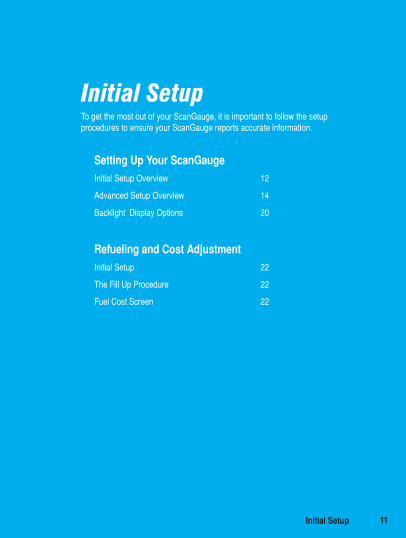
Initial SetupTo get the most out of your ScanGauge, it is important to follow the setup procedures to ensure your ScanGauge reports accurate information.
Setting Up Your ScanGaugeInitial Setup Overview 12
Advanced Setup Overview 14
Backlight Display Options 20
Refueling and Cost AdjustmentInitial Setup 22
The Fill Up Procedure 22
Fuel Cost Screen 22
Initial Setup 11
Setting Up Your ScanGauge
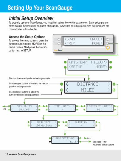
Initial Setup OverviewTo properly use your ScanGauge, you must first set up the vehicle parameters. Basic setup param-eters include, fuel tank size and units of measure. Advanced parameters are also available and are covered later in this chapter.
Access the Setup Options To access the setup screens, press the function button next to MORE on the Home Screen. Next press the function button next to SETUP.
<SCAN
<TRIP
GAUGE>
MORE>
<SETUP
<DISPLAY
MORE>
FILLUP>
< >
< >
DISTANCE
MILES
< >
< >
PRESSURE UNITS
PSI
< >
< >
TEMP UNITS
°F
< >
< >
CURRENCY
$
< >
< >
FUEL UNITS
GALLONS
< >
< >
TANK SIZE
100 Gallons
< >
EDIT>
ADV SETTINGS
See page 14 for Advanced Setup Options
Use the lower buttons to adjust the currently selected setup parameter
Use the upper buttons to move to the next or previous setup parameter
Displays the currently selected setup parameter
Loop
Loop
12 — www.ScanGauge.com
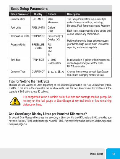
Basic Setup ParametersSetup Parameter Display Options Description
Distance Units DISTANCE MilesKilometers
The Setup Parameters include multiple units of measure settings, including Distance, Fuel, Temperature and Pressure.
Each is set independently of the others and can be used in any combination.
Making changes to these settings causes your ScanGauge to use these units when reporting and measuring data.
Fuel Units FUEL UNITS GallonsLiters
Temperature Units TEMP UNITS Fahrenheit(˚F)Celsius(˚C)
Pressure Units PRESSURE UNITS
PSIKPAMMIN
Tank Size TANK SIZE 0 - 9999 Gallons/liters
Is adjustable in 1-gallon or liter increments depending on how you set the FUEL UNITS parameter.
Currency Type CURRENCY $, £, ¥, 元 ,€ Choose the currency symbol ScanGauge should use to display monitor values.
Tips for Setting the Tank SizeThe size will use Gallons or Liters depending on the selection you made in the Fuel Units Screen (FUEL UNITS). If the size in the manual is not in whole units, use the next lower value. For instance, if the capacity is 80.5 gallons, use 80 gallons.
It is dangerous to run a vehicle out of fuel and can damage the fuel pump. Do not rely on the fuel gauge or ScanGauge at low fuel levels or low remaining distance or time.
Can ScanGauge Display Liters per Hundred Kilometers? By default, ScanGauge will express fuel economy in Liters per Hundred Kilometers (LHK), provided you have set fuel to LITERS and distance to KILOMETERS. For more information see LHK under Advanced Setup on page 14.
Initial Setup 13
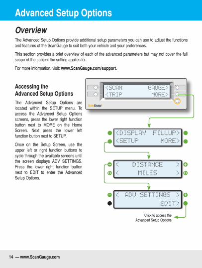
OverviewThe Advanced Setup Options provide additional setup parameters you can use to adjust the functions and features of the ScanGauge to suit both your vehicle and your preferences.
This section provides a brief overview of each of the advanced parameters but may not cover the full scope of the subject the setting applies to.
For more information, visit: www.ScanGauge.com/support.
Accessing the Advanced Setup OptionsThe Advanced Setup Options are located within the SETUP menu. To access the Advanced Setup Options screens, press the lower right function button next to MORE on the Home Screen. Next press the lower left function button next to SETUP.
Once on the Setup Screen, use the upper left or right function buttons to cycle through the available screens until the screen displays ADV SETTINGS. Press the lower right function button next to EDIT to enter the Advanced Setup Options.
<SCAN
<TRIP
GAUGE>
MORE>
<SETUP
<DISPLAY
MORE>
FILLUP>
< >
< >
DISTANCE
MILES
< >
EDIT>
ADV SETTINGS
Click to access the Advanced Setup Options
Advanced Setup Options
14 — www.ScanGauge.com
OverviewThe Advanced Setup Options provide additional setup parameters you can use to adjust the functions and features of the ScanGauge to suit both your vehicle and your preferences.
This section provides a brief overview of each of the advanced parameters but may not cover the full scope of the subject the setting applies to.
For more information, visit: www.ScanGauge.com/support.
Accessing the Advanced Setup OptionsThe Advanced Setup Options are located within the SETUP menu. To access the Advanced Setup Options screens, press the lower right function button next to MORE on the Home Screen. Next press the lower left function button next to SETUP.
Once on the Setup Screen, use the upper left or right function buttons to cycle through the available screens until the screen displays ADV SETTINGS. Press the lower right function button next to EDIT to enter the Advanced Setup Options.
<SCAN
<TRIP
GAUGE>
MORE>
<SETUP
<DISPLAY
MORE>
FILLUP>
< >
< >
DISTANCE
MILES
< >
EDIT>
ADV SETTINGS
Click to access the Advanced Setup Options
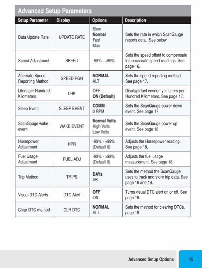
Advanced Setup ParametersSetup Parameter Display Options Description
Data Update Rate UPDATE RATE
SlowNormalFastMax
Sets the rate in which ScanGauge reports data. See below.
Speed Adjustment SPEED -99% - +99%Sets the speed offset to compensate for inaccurate speed readings. See page 16.
Alternate Speed Reporting Method
SPEED PGNNORMALALT
Sets the speed reporting method See page 17.
Liters per Hundred Kilometers
LHKOFF ON (Default)
Displays fuel economy in Liters per Hundred Kilometers. See page 17.
Sleep Event SLEEP EVENTCOMM 0 RPM
Sets the ScanGauge power down event. See page 17.
ScanGauge wake event
WAKE EVENTNormal VoltsHigh VoltsLow Volts
Sets the ScanGauge power up event. See page 18.
Horsepower Adjustment
HPR-99% - +99%(Default 0)
Adjusts the Horsepower reading. See page 18.
Fuel Usage Adjustment
FUEL ADJ-99% - +99%(Default 0)
Adjusts the fuel usage measurement. See page 18.
Trip Method TRIPSDAYsAB
Sets the method the ScanGauge uses to track and store trip data. See page 18 and 19.
Visual DTC Alerts DTC AlertOFFON
Turns visual DTC alert on or off. See page 19.
Clear DTC method CLR DTCNORMALALT
Sets the method for clearing DTCs. page 19.
Advanced Setup Options 15
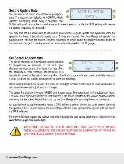
Set the Update RateYou can adjust the rate in which ScanGauge reports data. The update rate defaults to NORMAL which updates the display about every 2 seconds. The SLOW setting will reduce the update frequency to every 4 seconds, while the FAST setting will increase the update frequency to 1 second.
You may also set the update rate to MAX which allows ScanGauge to update displayed data at the full speed of the buss. If the vehicle reports data 10 times per second, then ScanGauge will update the gauge screen 10 times per second. In some instances, this may cause the display to appear blurry as the numbers change too quickly to read — particularly with speed and RPM gauges.
Set Speed AdjustmentsThe speed indicated by ScanGauge can be adjusted to compensate for changes in tire size, gear changes, tire wear or any other factor that may affect the accuracy of your vehicle’s speedometer. It is important to note that this adjustment only affects the ScanGauge’s indicated speed and distances, and it does not affect the vehicle speedometer or odometer readings.
While viewing the SPEED Screen, the lower left and right function buttons can be used to increase or decrease the selected adjustment in 1% steps.
The upper line displays the word SPEED and a percentage. The percentage is the adjustment factor. The lower line displays 2 numbers: the left number is the speed reported by the vehicle and the number on the right is the speed that will be shown by the ScanGauge after applying the correction factor.
An accurate way to set the speed is to use a GPS. With one person driving, the other person observes the speed on the GPS and adjusts the percentage until the lower right number agrees with the speed the GPS indicates.
For more information about the various methods of calculating your speed adjustment, visit us online at www.ScanGauge.com/quick-tips/.
IMPORTANT: OBSERVE ALL SPEED LIMITS AND DRIVE SAFELY WHILE MAKING THESE ADJUSTMENTS. THE DRIVER MUST NOT BE DISTRACTED BY TRYING TO MAKE THESE ADJUSTMENTS WHILE DRIVING.
< >
< >
UPDATE RATE
NORMAL
< >
< >
SPEED 0%
50> 50
16 — www.ScanGauge.com
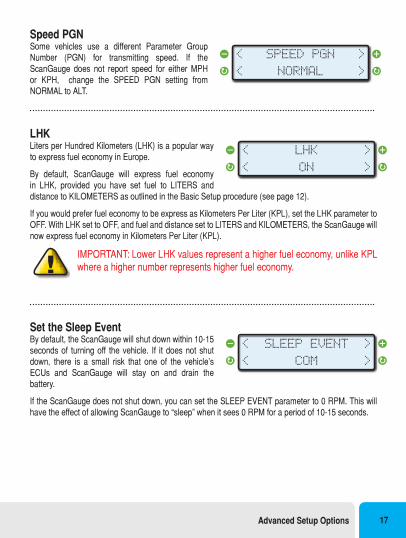
Speed PGNSome vehicles use a different Parameter Group Number (PGN) for transmitting speed. If the ScanGauge does not report speed for either MPH or KPH, change the SPEED PGN setting from NORMAL to ALT.
LHKLiters per Hundred Kilometers (LHK) is a popular way to express fuel economy in Europe.
By default, ScanGauge will express fuel economy in LHK, provided you have set fuel to LITERS and distance to KILOMETERS as outlined in the Basic Setup procedure (see page 12).
If you would prefer fuel economy to be express as Kilometers Per Liter (KPL), set the LHK parameter to OFF. With LHK set to OFF, and fuel and distance set to LITERS and KILOMETERS, the ScanGauge will now express fuel economy in Kilometers Per Liter (KPL).
IMPORTANT: Lower LHK values represent a higher fuel economy, unlike KPL where a higher number represents higher fuel economy.
Set the Sleep EventBy default, the ScanGauge will shut down within 10-15 seconds of turning off the vehicle. If it does not shut down, there is a small risk that one of the vehicle’s ECUs and ScanGauge will stay on and drain the battery.
If the ScanGauge does not shut down, you can set the SLEEP EVENT parameter to 0 RPM. This will have the effect of allowing ScanGauge to “sleep” when it sees 0 RPM for a period of 10-15 seconds.
< >
< >
SPEED PGN
NORMAL
< >
< >
LHK
ON
< >
< >
SLEEP EVENT
COM
Advanced Setup Options 17
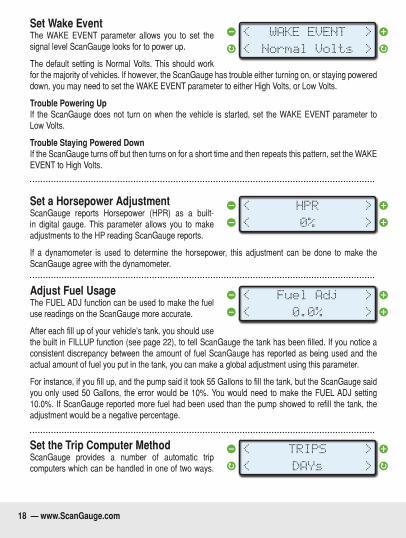
Set Wake EventThe WAKE EVENT parameter allows you to set the signal level ScanGauge looks for to power up.
The default setting is Normal Volts. This should work for the majority of vehicles. If however, the ScanGauge has trouble either turning on, or staying powered down, you may need to set the WAKE EVENT parameter to either High Volts, or Low Volts.
Trouble Powering UpIf the ScanGauge does not turn on when the vehicle is started, set the WAKE EVENT parameter to Low Volts.
Trouble Staying Powered DownIf the ScanGauge turns off but then turns on for a short time and then repeats this pattern, set the WAKE EVENT to High Volts.
Set a Horsepower AdjustmentScanGauge reports Horsepower (HPR) as a built-in digital gauge. This parameter allows you to make adjustments to the HP reading ScanGauge reports.
If a dynamometer is used to determine the horsepower, this adjustment can be done to make the ScanGauge agree with the dynamometer.
Adjust Fuel UsageThe FUEL ADJ function can be used to make the fuel use readings on the ScanGauge more accurate.
After each fill up of your vehicle’s tank, you should use the built in FILLUP function (see page 22), to tell ScanGauge the tank has been filled. If you notice a consistent discrepancy between the amount of fuel ScanGauge has reported as being used and the actual amount of fuel you put in the tank, you can make a global adjustment using this parameter.
For instance, if you fill up, and the pump said it took 55 Gallons to fill the tank, but the ScanGauge said you only used 50 Gallons, the error would be 10%. You would need to make the FUEL ADJ setting 10.0%. If ScanGauge reported more fuel had been used than the pump showed to refill the tank, the adjustment would be a negative percentage.
Set the Trip Computer MethodScanGauge provides a number of automatic trip computers which can be handled in one of two ways.
< >
< >
WAKE EVENT
Normal Volts
< >
< >
HPR
0%
< >
< >
Fuel Adj
0.0%
< >
< >
TRIPS
DAYs
18 — www.ScanGauge.com
Trips can be automatically stored as TODAY and PREVIOUS DAY (the default method), or as TRIP A and TRIP B.
The ScanGauge relies upon the power supplied by the diagnostic connector to write TODAY and PREVIOUS DAY trip data to memory once the vehicle has been shut off. Some vehicles will cut power to the diagnostic connector the moment the vehicle is shut off, causing ScanGauge to be unable to write the trip data. If this is the case for your vehicle, you should set the TRIPS parameter to AB. This will change the automatic trip storage method from TODAY and PREVIOUS DAY, to TRIP A and TRIP B methods. To learn more about the differences between the two trip storage methods, refer to the Trip Computer section beginning on page 28.
To test which method your vehicle should use, you can simply observe the ScanGauge when you shut off the vehicle. If the ScanGauge backlight shuts off in less than 2 seconds of turning off the vehicle, then you should set the TRIPS parameters to AB
While set to the AB method, ScanGauge will automatically track all trips through the TRIP A and TRIP B trip computers.
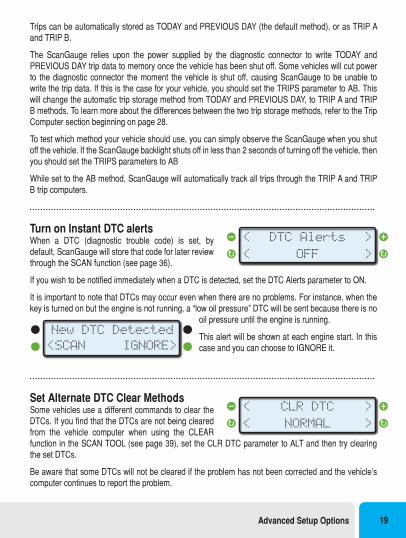
Turn on Instant DTC alertsWhen a DTC (diagnostic trouble code) is set, by default, ScanGauge will store that code for later review through the SCAN function (see page 36).
If you wish to be notified immediately when a DTC is detected, set the DTC Alerts parameter to ON.
It is important to note that DTCs may occur even when there are no problems. For instance, when the key is turned on but the engine is not running, a “low oil pressure” DTC will be sent because there is no
oil pressure until the engine is running.
This alert will be shown at each engine start. In this case and you can choose to IGNORE it.
Set Alternate DTC Clear MethodsSome vehicles use a different commands to clear the DTCs. If you find that the DTCs are not being cleared from the vehicle computer when using the CLEAR function in the SCAN TOOL (see page 39), set the CLR DTC parameter to ALT and then try clearing the set DTCs.
Be aware that some DTCs will not be cleared if the problem has not been corrected and the vehicle’s computer continues to report the problem.
< >
< >
DTC Alerts
OFF
New DTC Detected
<SCAN IGNORE>
< >
< >
CLR DTC
NORMAL
Advanced Setup Options 19
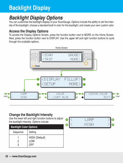
Backlight Display OptionsYou can customize the backlight display of your ScanGauge. Options include the ability to set the inten-sity of the backlight, choose a standard built-in color for the backlight, and create your own custom color.
Access the Display OptionsTo access the Display Options Screen, press the function button next to MORE on the Home Screen. Next, press the function button next to DISPLAY. Use the upper left and right function buttons to cycle through the available options.
<SCAN
<TRIP
GAUGE>
MORE>
Home Screen
< LIGHT BLUE
COLOR
>
< > CUSTOM COLOR
EDIT>
< >
<SETUP
<DISPLAY
MORE>
FILLUP>
< HIGH
LAMP
>
< >LoopLoop
Change the Backlight IntensityUse the lower left and right function buttons to adjust the backlight intensity. Options include:
Backlight Color Options
Sequence Setting
123
HIGH (Default)LOWOFF
< HIGH
LAMP
>
< >
Backlight Display
20 — www.ScanGauge.com
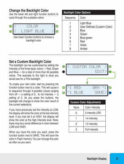
Change the Backlight ColorUse the lower left and right function buttons to cycle through the available colors.
Use lower function buttons to choose a backlight color
< LIGHT BLUE
COLOR
>
< >
Set a Custom Backlight ColorThe backlight can be customized by setting the intensity of the three basic colors — Red, Green and Blue — for a total of more than 60 possible colors. The example to the right is what you would see for a Pink backlight.
To create your own color, start by pressing the function button next to a color. This will cause it to sequence through 4 possible values ranging from off — a setting of 0, to full intensity — a setting of 3. As you press the buttons, the backlight will change to show the color result of the current selections.
If you have previously set the intensity at LOW, the display will show the color at the low intensity level. If you had set it at HIGH, the display will show the color at the high intensity level. Note: there may be a small difference in color between LOW and HIGH.
When you have the color you want, press the function button next to SAVE. This will save the color in Flash memory. You can change the color as often as you want.
Backlight Color Options
Sequence Color
12345678
Light BlueUser Defined (Custom Color)Blue Green Blue-greenRedVioletAmber
CUSTOM COLOR
EDIT>
< >
^1 BLUE
^1 RED
SAVE>
GRN ^1
Custom Color Adjustments
Value Color Intensity
0 0 intensity (Off)
1 1/4 intensity
2 1/2 intensity
3 Full intensity
Backlight Display 21

Refueling and Cost Adjustment
Improving the Accuracy of Your ScanGaugeThe accuracy of your ScanGauge can be improved by following the Refueling and Cost Adjustment procedures outlined in this section. These functions directly effect the fuel based trip computers – TANK and TANK TO EMPTY. See page 32.
The Fill up FunctionThe FILLUP function allows you to adjust and enter the fuel level and cost values to help ScanGauge maintain accurate TO EMPTY and FUEL COST computations. During initial setup, if you are not filling the tank to capacity, you will need to estimate the amount of fuel in the tank.
Initial SetupTo set the tank level initially, access the FILLUP screen and use the upper left and right function buttons to adjust the “TANK=” value to what you estimate is in the tank.
For instance, if your vehicle’s fuel gauge indicates there is a half a tank of fuel, then adjust the “TANK=” value to match 1/2 of the tank capacity.
Using the FILLUP ScreenUse the FILLUP screen each time you put fuel in the tank. Adjust the number shown in the top line using the upper left and right function buttons until the number matches the amount of fuel you put in the tank.
You can increase the number in 10 gallon/liter steps and decrease in 1 gallon/liter steps.
If you’re tank is full, press the function button next to “+10” until the “TANK=” value is the same as the tank capacity.
Fuel Cost ScreenWhen you’re done adjusting the fuel, press the NEXT button to access the Fuel Cost Screen. Use the upper left and right function buttons to adjust the fuel cost, then press SAVE.
<SCAN
<TRIP
GAUGE>
MORE>
<SETUP
<DISPLAY
MORE>
FILLUP>
0
NEXT>Tank= 85
<-1 +10>
Fuel Cost
<
SAVE>
>$4.10
Push the SAVE button to complete the FILLUP process and reset the TRIP parameters related to fuel.
FILLUP Screen
Fuel Cost Screen
22 — www.ScanGauge.com
Helpful Hints•If you fill up your fuel tank with your vehicle on an incline, it can have an effect on the amount of fuel
the pump can dispense into your tank.
•When filling your tank, let the pump shut off automatically. Do not top off.
•To maintain the most accurate “TO EMPTY” information, it is best to fill the tank to its capacity
•If you have no need to track the time and distance values of the “TO EMPTY’ and “TANK” but still want to track fuel costs, you can simply skip the FILLUP Screen by pressing NEXT and then entering the Fuel Cost. When you’re done, press the lower right function button next to SAVE.
Refueling and Cost Adjustment 23
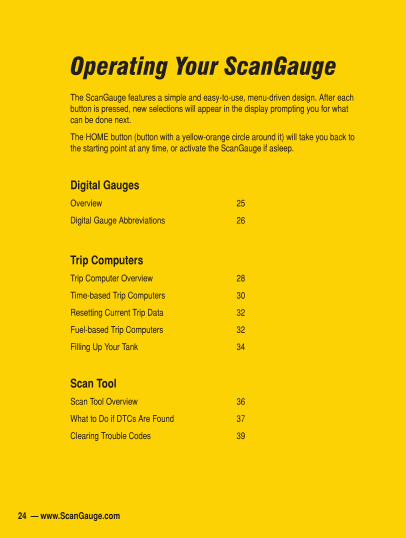
Operating Your ScanGaugeThe ScanGauge features a simple and easy-to-use, menu-driven design. After each button is pressed, new selections will appear in the display prompting you for what can be done next.
The HOME button (button with a yellow-orange circle around it) will take you back to the starting point at any time, or activate the ScanGauge if asleep.
Digital GaugesOverview 25
Digital Gauge Abbreviations 26
Trip ComputersTrip Computer Overview 28
Time-based Trip Computers 30
Resetting Current Trip Data 32
Fuel-based Trip Computers 32
Filling Up Your Tank 34
Scan ToolScan Tool Overview 36
What to Do if DTCs Are Found 37
Clearing Trouble Codes 39
24 — www.ScanGauge.com
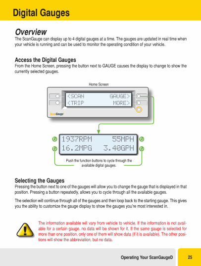
OverviewThe ScanGauge can display up to 4 digital gauges at a time. The gauges are updated in real time when your vehicle is running and can be used to monitor the operating condition of your vehicle.
Access the Digital GaugesFrom the Home Screen, pressing the button next to GAUGE causes the display to change to show the currently selected gauges.
Push the function buttons to cycle through the available digital gauges.
<SCAN
<TRIP
GAUGE>
MORE>
Home Screen
1937RPM
16.2MPG
55MPH
3.40GPH
Selecting the GaugesPressing the button next to one of the gauges will allow you to change the gauge that is displayed in that position. Pressing a button repeatedly, allows you to cycle through all the available gauges.
The selection will continue through all of the gauges and then loop back to the starting gauge. This gives you the ability to customize the gauge display to show the gauges you’re most interested in.
The information available will vary from vehicle to vehicle. If the information is not avail-able for a certain gauge, no data will be shown for it. If the same gauge is selected for more than one position, only one of them will show data (if it is available). The other posi-tions will show the abbreviation, but no data.
Digital Gauges
Operating Your ScanGaugeD 25
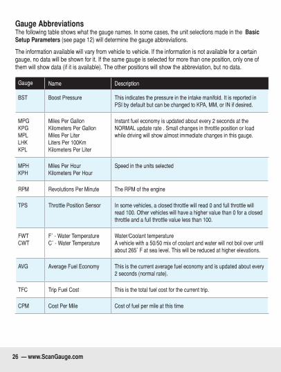
Gauge AbbreviationsThe following table shows what the gauge names. In some cases, the unit selections made in the Basic Setup Parameters (see page 12) will determine the gauge abbreviations.
The information available will vary from vehicle to vehicle. If the information is not available for a certain gauge, no data will be shown for it. If the same gauge is selected for more than one position, only one of them will show data (if it is available). The other positions will show the abbreviation, but no data.
Gauge Name Description
BST Boost Pressure This indicates the pressure in the intake manifold. It is reported in PSI by default but can be changed to KPA, MM, or IN if desired.
MPGKPGMPLLHKKPL
Miles Per GallonKilometers Per GallonMiles Per LiterLiters Per 100KmKilometers Per Liter
Instant fuel economy is updated about every 2 seconds at the NORMAL update rate . Small changes in throttle position or load while driving will show almost immediate changes in this gauge.
MPHKPH
Miles Per HourKilometers Per Hour
Speed in the units selected
RPM Revolutions Per Minute The RPM of the engine
TPS Throttle Position Sensor In some vehicles, a closed throttle will read 0 and full throttle will read 100. Other vehicles will have a higher value than 0 for a closed throttle and a full throttle value less than 100.
FWT CWT
F˚-WaterTemperatureC˚-WaterTemperature
Water/Coolant temperature A vehicle with a 50/50 mix of coolant and water will not boil over until about265˚Fatsealevel.Thiswillbereducedathigherelevations.
AVG Average Fuel Economy This is the current average fuel economy and is updated about every 2 seconds (normal rate).
TFC Trip Fuel Cost This is the total fuel cost for the current trip.
CPM Cost Per Mile Cost of fuel per mile at this time
26 — www.ScanGauge.com
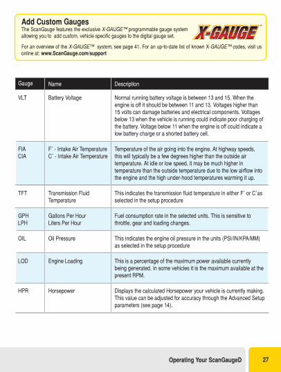
Gauge Name Description
VLT Battery Voltage Normal running battery voltage is between 13 and 15. When the engine is off it should be between 11 and 13. Voltages higher than 15 volts can damage batteries and electrical components. Voltages below 13 when the vehicle is running could indicate poor charging of the battery. Voltage below 11 when the engine is off could indicate a low battery charge or a shorted battery cell.
FIA CIA
F˚-IntakeAirTemperatureC˚-IntakeAirTemperature
Temperature of the air going into the engine. At highway speeds, this will typically be a few degrees higher than the outside air temperature. At idle or low speed, it may be much higher in temperature than the outside temperature due to the low airflow into the engine and the high under-hood temperatures warming it up.
TFT Transmission Fluid Temperature
ThisindicatesthetransmissionfluidtemperatureineitherF˚orC˚asselected in the setup procedure
GPH LPH
Gallons Per Hour Liters Per Hour
Fuel consumption rate in the selected units. This is sensitive to throttle, gear and loading changes.
OIL Oil Pressure This indicates the engine oil pressure in the units (PSI/IN/KPA/MM)as selected in the setup procedure
LOD Engine Loading This is a percentage of the maximum power available currently being generated. In some vehicles it is the maximum available at the present RPM.
HPR Horsepower Displays the calculated Horsepower your vehicle is currently making. This value can be adjusted for accuracy through the Advanced Setup parameters (see page 14).
Add Custom GaugesThe ScanGauge features the exclusive X-GAUGE™ programmable gauge system allowing you to add custom, vehicle specific gauges to the digital gauge set.
For an overview of the X-GAUGE™ system, see page 41. For an up-to-date list of known X-GAUGE™ codes, visit us online at: www.ScanGauge.com/support
Operating Your ScanGaugeD 27
Trip Computers
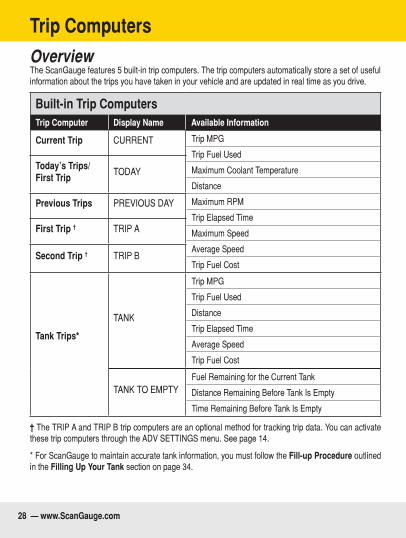
Overview The ScanGauge features 5 built-in trip computers. The trip computers automatically store a set of useful information about the trips you have taken in your vehicle and are updated in real time as you drive.
Built-in Trip ComputersTrip Computer Display Name Available Information
Current Trip CURRENT Trip MPG
Trip Fuel Used
Maximum Coolant Temperature
Distance
Maximum RPM
Trip Elapsed Time
Maximum Speed
Average Speed
Trip Fuel Cost
Today’s Trips/First Trip
TODAY
Previous Trips PREVIOUS DAY
First Trip † TRIP A
Second Trip † TRIP B
Tank Trips*
TANK
Trip MPG
Trip Fuel Used
Distance
Trip Elapsed Time
Average Speed
Trip Fuel Cost
TANK TO EMPTYFuel Remaining for the Current Tank
Distance Remaining Before Tank Is Empty
Time Remaining Before Tank Is Empty
† The TRIP A and TRIP B trip computers are an optional method for tracking trip data. You can activate these trip computers through the ADV SETTINGS menu. See page 14.
* For ScanGauge to maintain accurate tank information, you must follow the Fill-up Procedure outlined in the Filling Up Your Tank section on page 34.
28 — www.ScanGauge.com
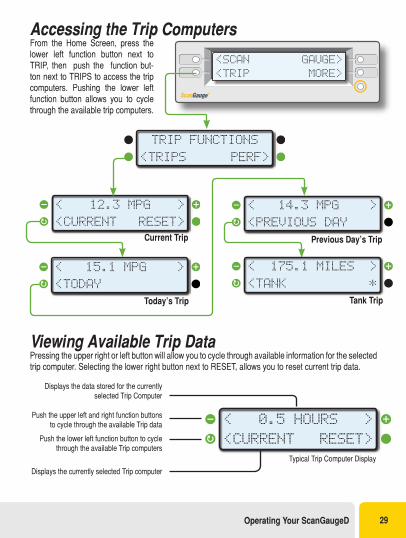
Accessing the Trip ComputersFrom the Home Screen, press the lower left function button next to TRIP, then push the function but-ton next to TRIPS to access the trip computers. Pushing the lower left function button allows you to cycle through the available trip computers.
Viewing Available Trip DataPressing the upper right or left button will allow you to cycle through available information for the selected trip computer. Selecting the lower right button next to RESET, allows you to reset current trip data.
Displays the data stored for the currently selected Trip Computer
Push the upper left and right function buttons to cycle through the available Trip data
Push the lower left function button to cycle through the available Trip computers
Displays the currently selected Trip computer
Typical Trip Computer Display
< >
<CURRENT RESET>
0.5 HOURS
Current Trip
Today’s Trip
Previous Day’s Trip
Tank Trip
< >
<CURRENT RESET>
12.3 MPG
< >
<TODAY
15.1 MPG
< >
<PREVIOUS DAY
14.3 MPG
< >
<TANK *
175.1 MILES
<SCAN
<TRIP
GAUGE>
MORE>
<TRIPS PERF>
TRIP FUNCTIONS
Operating Your ScanGaugeD 29
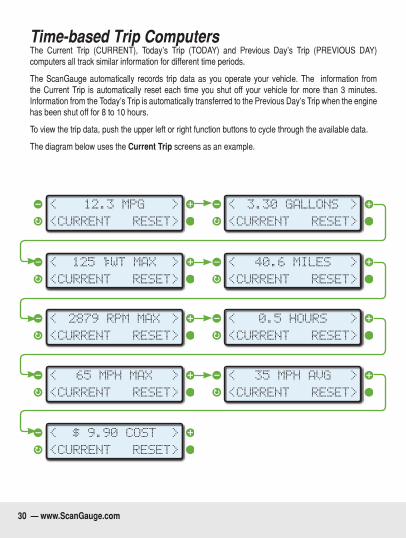
Time-based Trip ComputersThe Current Trip (CURRENT), Today’s Trip (TODAY) and Previous Day’s Trip (PREVIOUS DAY) computers all track similar information for different time periods.
The ScanGauge automatically records trip data as you operate your vehicle. The information from the Current Trip is automatically reset each time you shut off your vehicle for more than 3 minutes. Information from the Today’s Trip is automatically transferred to the Previous Day’s Trip when the engine has been shut off for 8 to 10 hours.
To view the trip data, push the upper left or right function buttons to cycle through the available data.
The diagram below uses the Current Trip screens as an example.
< >
<CURRENT RESET>
3.30 GALLONS
< >
<CURRENT RESET>
40.6 MILES
< >
<CURRENT RESET>
0.5 HOURS
< >
<CURRENT RESET>
35 MPH AVG
< >
<CURRENT RESET>
12.3 MPG
< >
<CURRENT RESET>
125 WT MAX
< >
<CURRENT RESET>
2879 RPM MAX
< >
<CURRENT RESET>
65 MPH MAX
< >
<CURRENT RESET>
$ 9.90 COST
30 — www.ScanGauge.com
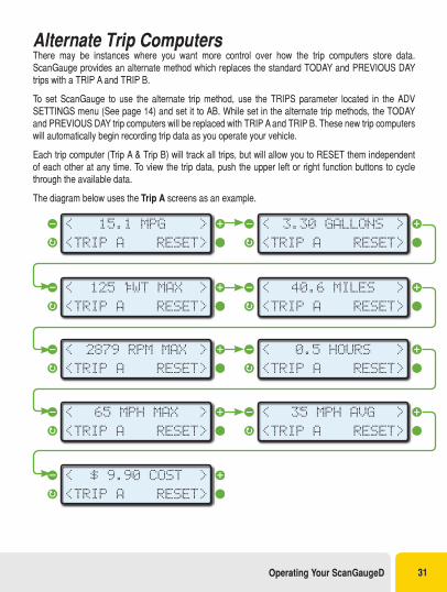
Alternate Trip ComputersThere may be instances where you want more control over how the trip computers store data. ScanGauge provides an alternate method which replaces the standard TODAY and PREVIOUS DAY trips with a TRIP A and TRIP B.
To set ScanGauge to use the alternate trip method, use the TRIPS parameter located in the ADV SETTINGS menu (See page 14) and set it to AB. While set in the alternate trip methods, the TODAY and PREVIOUS DAY trip computers will be replaced with TRIP A and TRIP B. These new trip computers will automatically begin recording trip data as you operate your vehicle.
Each trip computer (Trip A & Trip B) will track all trips, but will allow you to RESET them independent of each other at any time. To view the trip data, push the upper left or right function buttons to cycle through the available data.
The diagram below uses the Trip A screens as an example.
< >
<TRIP A RESET>
3.30 GALLONS
< >
<TRIP A RESET>
40.6 MILES
< >
<TRIP A RESET>
0.5 HOURS
< >
<TRIP A RESET>
35 MPH AVG
< >
<TRIP A
15.1 MPG
RESET>
< >
<TRIP A RESET>
125 WT MAX
< >
<TRIP A RESET>
2879 RPM MAX
< >
<TRIP A RESET>
65 MPH MAX
< >
<TRIP A RESET>
$ 9.90 COST
Operating Your ScanGaugeD 31
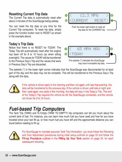
Resetting Current Trip DataThe Current Trip data is automatically reset after about 3 minutes of the ScanGauge being asleep.
You can reset the trip data at any time for the Current Trip computers. To reset trip data, simply press the function button next to RESET as shown in the example above.
Today’s Trip DataNotice that there is no RESET for TODAY. The Today Trip will automatically reset after the engine has been off for 8 to 10 hours (as when sitting overnight). The values for TODAY will be transferred to the Previous Day’s Trip and the values that were in Previous Day’s Trip are discarded.
The asterisk (*) in the lower right corner indicates that the ScanGauge was disconnected for at least part of the day and the data may not be complete. This will be transferred to the Previous Day’s Trip along with the data.
If the vehicle is driven early in the morning and then not again until late that evening, the data will be transferred to the previous day. If the vehicle is driven until late at night and then used again very early in the morning, the data will stay in the Today’s Trip. The end of the Today’s Trip requires the vehicle be off, the ScanGauge connected, and the vehicle not driven for 8 to 10 hours.
Fuel-based Trip ComputersThe Tank Trip (TANK) and To Empty (TANK TO EMPTY) trip computers can tell you much about the current tank of fuel. For instance, you can learn how much fuel you have used and how far you have traveled since your last fill-up, or how much fuel you have left and the approximate distance you can travel before needing to fill up.
For ScanGauge to maintain accurate Tank Trip information, you must follow the Refueling and Cost Adjustment procedures during initial setup outlined on page 22 and follow the Fill-up Procedure outlined in the Filling Up Your Tank section on page 34, for each subsequent refueling.
Push the lower right button to reset all trip data for the CURRENT trip
< >
<CURRENT RESET>
12.3 MPG
The asterisk (*) indicates the ScanGauge may have incomplete trip data
< >
<TODAY *
65 MPH MAX
32 — www.ScanGauge.com
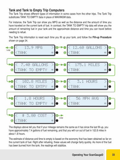
Tank and Tank to Empty Trip ComputersThe Tank Trip shows different types of information in some cases from the other trips. The Tank Trip substitutes TANK TO EMPTY data in place of MAXIMUM data.
For instance, the Tank Trip can show you MPG as well as the distance and the amount of time you have traveled on the current tank of fuel. In contrast, the TANK TO EMPTY trip data will show you the amount of remaining fuel in your tank and the approximate distance and time you can travel before needing to refuel.
The Tank Trip information is reset each time you fill up your tank, and follow the Fill-up Procedure shown on page 34.
< >
<TANK *
12.60 GALLONS
< >
<TANK *
175.1 MILES
< >
<TANK *
3.1 HOURS
< >
<TANK *
56 MPH AVG
< >
<TANK *
13.9 MPG
< >
<TANK TO EMPTY *
7.40 GALLONS
< >
<TANK TO EMTPY *
102.8 MILES
< >
<TANK TO EMPTY *
1.8 HOURS
< >
<TANK *
$ 3.80 COSTLoop
Loop
The displays above tell you that if your mileage remains the same as it has since the last fill-up, you have approximately 7.4 gallons of fuel remaining, and that you will run out of fuel in 102.8 miles in about 1.8 hours.
The estimate of distance and time to empty is based on the economy that has been obtained so far on the current tank of fuel. Right after refueling, these values will change fairly quickly. As more of the fuel has been burned from the tank, the readings will stabilize.
Operating Your ScanGaugeD 33
It is possible to see the distance and time to empty increase as you drive. The distance can increase as you drive at a steady fuel-efficient speed. This causes the fuel economy for the tank to rise; and applying this higher fuel efficiency to the fuel remaining in the tank can actually result in more remaining distance. If you drive slower than the average speed of the tank so far, the time to empty can increase.
To maintain accurate To Empty information, you must use the following FILLUP procedure shown under Filling Up Your Tank to indicate the vehicle tank has been refilled. It is also necessary to fill the tank to make the TO EMPTY information correct.
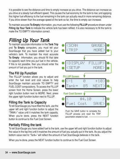
Filling Up Your TankTo maintain accurate information in the Tank Trip and To Empty computers, you must tell your ScanGauge that you have added fuel to your vehicle’s tank. To maintain the most accurate To Empty information, you should fill that take to capacity each time you put fuel in the vehicle. If this is not possible, then you should enter the amount of fuel you put in the tank.
The Fill Up FunctionThe FILLUP function allows you to adjust and enter the fuel level and cost values to help ScanGauge maintain accurate TO EMPTY and FUEL COST computations. To access the FILLUP screen from the Home Screen, press the lower right function button next to MORE. Next, press the upper right function button next to FILLUP.
Filling the Tank to CapacityTo tell ScanGauge you have filled the tank, use the upper left and right function button to adjust the “TANK=” value until it matches the tank capacity. When you’re done, press the NEXT function button to continue to the Fuel Cost Screen.
Partially Filling the tankTo tell ScanGauge you have added fuel to the tank, use the upper left and right function button to adjust the value in the top line until it matches the amount of fuel you actually put in the tank. As you adjust the bottom value next to “Tank=” will reflect the amount of fuel ScanGauge believes in the tank.
When you’re done, press the NEXT function button to continue to the Fuel Cost Screen
<SCAN
<TRIP
GAUGE>
MORE>
<SETUP
<DISPLAY
MORE>
FILLUP>
0
NEXT>Tank= 85
<-1 +10>
Fuel Cost
<
SAVE>
>$4.10
Push the SAVE button to complete the FILLUP process and reset the TRIP parameters related to fuel.
FILLUP Screen
Fuel Cost Screen
34 — www.ScanGauge.com
FILLUP Screen
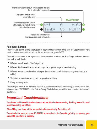
Displays the amount of fuel added to the tank
Push to decrease the amount of fuel added to the tank in one
gallon/liter increments
Push to increase the amount of fuel added to the tank by 10 gallons/liters increments
Displays the amount of fuel ScanGauge believes is in the tank.
0
NEXT>Tank= 85
<-1 +10>
Fuel Cost ScreenThe Fuel Cost screen allows ScanGauge to track accurate trip fuel costs. Use the upper left and right function buttons to adjust the fuel cost. When you’re done, press SAVE
There will be variations in the agreement of the pump fuel used and the ScanGauge indicated fuel use from tank to tank due to:
•Different shutoff levels of the fuel pumps
•Different tilt of the vehicle at the fuel pump due to ground slope or vehicle loading
•Different temperature of the fuel (changes density – best to refill in the morning when the fuel is colder)
•Variations in vehicle sensors due to temperature and time
•Pump accuracy limits
These are just some of the variables that limit absolute accuracy and show why you should never trust a low reading of DISTANCE in the Tank to Empty Trip to believe you will be able to make it to the next gas station.
Important Considerations You should refill the vehicle when there is above 50 miles/km remaining. Pushing below 50 could result in running out of fuel.
When filling your tank, let the pump shut off automatically. Do not top off.
To maintain the most accurate TO EMPTY information in the ScanGauge’s trip computers, you should fill your tank to capacity.
Operating Your ScanGaugeD 35
Scan Tool
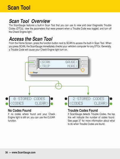
Scan Tool OverviewThe ScanGauge features a built-in Scan Tool that you can use to view and clear Diagnostic Trouble Codes (DTCs), view the parameters that were present when a Trouble Code was logged, and turn off the Check Engine light.
Access the Scan ToolFrom the Home Screen, press the function button next to SCAN to access the built-in Scan Tool. When you press SCAN, the ScanGauge immediately checks your vehicle’s computer for any DTCs. Generally, a Trouble Code will cause your Check Engine light turn on.
<SCAN
<TRIP
GAUGE>
MORE>
2 STORED CODES
<CODES CLEAR>
0 STORED CODES
<CODES CLEAR>
No Codes FoundIf no codes where found and your Check Engine light is still on, you can use the CLEAR function.
Trouble Codes FoundIf ScanGauge detects Trouble Codes, the top line will indicate the number of codes found. See page 37 for more information about what to do when Trouble Codes are found.
36 — www.ScanGauge.com
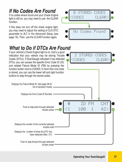
If No Codes Are FoundIf no codes where found and your Check Engine light is still on, you may need to use the CLEAR function.
If this does not turn off the check engine light, you may need to adjust the setting of CLR DTC parameter to ALT in the Advanced Setup (see page 19). Then, use the CLEAR function again.
What to Do if DTCs Are FoundIf your vehicle’s Check Engine light is on, that’s a good indication that your vehicle may be storing Trouble Codes (DTCs). If ScanGauge indicated it has detected DTCs, you can access the specific Error Code ID (ID) and related Failure Mode ID (FM) by pressing the function button next to CODES. If more then one code is stored, you can use the lower left and right function buttons to step through the stored codes.
0 STORED CODES
<CODES CLEAR>
No Codes Found
Displays the Error Code ID Number
Displays the Failure Mode ID. See page 38 for list of standard modes
Displays the number of times the DTC has been detected (Max 127)
Displays the number of the currently selected trouble code
Push to step back through detected trouble codes
Push to step forward through detected trouble codes
ID
100
FM
1
#
<1
CNT
42>
2 STORED CODES
<CODES CLEAR>
Operating Your ScanGaugeD 37
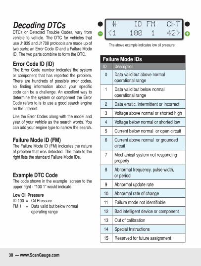
Decoding DTCsDTCs or Detected Trouble Codes, vary from vehicle to vehicle. The DTC for vehicles that use J1939 and J1708 protocols are made up of two parts; an Error Code ID and a Failure Mode ID. The two parts combine to form the DTC.
Error Code ID (ID)The Error Code number indicates the system or component that has reported the problem. There are hundreds of possible error codes, so finding information about your specific code can be a challenge. An excellent way to determine the system or component the Error Code refers to is to use a good search engine on the Internet.
Use the Error Codes along with the model and year of your vehicle as the search words. You can add your engine type to narrow the search.
Failure Mode ID (FM)The Failure Mode ID (FM) indicates the nature of problem that was detected. The table to the right lists the standard Failure Mode IDs.
Example DTC CodeThe code shown in the example screen to the upper right - “100 1” would indicate:
Low Oil Pressure ID 100 = Oil Pressure FM 1 = Data valid but below normal operating range
Failure Mode IDsID Description
0 Data valid but above normal operational range
1 Data valid but below normal operational range
2 Data erratic, intermittent or incorrect
3 Voltage above normal or shorted high
4 Voltage below normal or shorted low
5 Current below normal or open circuit
6 Current above normal or grounded circuit
7 Mechanical system not responding properly
8 Abnormal frequency, pulse width, or period
9 Abnormal update rate
10 Abnormal rate of change
11 Failure mode not identifiable
12 Bad intelligent device or component
13 Out of calibration
14 Special Instructions
15 Reserved for future assignment
ID
100
FM
1
#
<1
CNT
42>
The above example indicates low oil pressure.
38 — www.ScanGauge.com
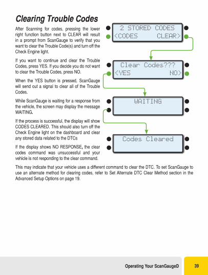
Clearing Trouble CodesAfter Scanning for codes, pressing the lower right function button next to CLEAR will result in a prompt from ScanGauge to verify that you want to clear the Trouble Code(s) and turn off the Check Engine light.
If you want to continue and clear the Trouble Codes, press YES. If you decide you do not want to clear the Trouble Codes, press NO.
When the YES button is pressed, ScanGauge will send out a signal to clear all of the Trouble Codes.
While ScanGauge is waiting for a response from the vehicle, the screen may display the message WAITING.
If the process is successful, the display will show CODES CLEARED. This should also turn off the Check Engine light on the dashboard and clear any stored data related to the DTCs
If the display shows NO RESPONSE, the clear codes command was unsuccessful and your vehicle is not responding to the clear command.
This may indicate that your vehicle uses a different command to clear the DTC. To set ScanGauge to use an alternate method for clearing codes, refer to Set Alternate DTC Clear Method section in the Advanced Setup Options on page 19.
Clear Codes???
<YES NO>
WAITING
Codes Cleared
2 STORED CODES
<CODES CLEAR>
Operating Your ScanGaugeD 39
X-GAUGE™
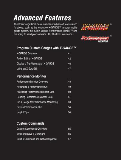
Advanced FeaturesThe ScanGaugeII includes a number of advanced features and functions, such as the exclusive X-GAUGE™ programmable gauge system, the built-in vehicle Performance Monitor™ and the ability to send your vehicle’s ECU Custom Commands.
Program Custom Gauges with X-GAUGE™X-GAUGE Overview 41
Add or Edit an X-GAUGE 42
Display a Trip Value as an X-GAUGE 46
Using an X-GAUGE 47
Performance MonitorPerformance Monitor Overview 48
Recording a Performance Run 49
Accessing Performance Monitor Data 50
Reading Performance Monitor Data 51
Set a Gauge for Performance Monitoring 53
Save a Performance Run 54
Helpful Tips 54
Custom CommandsCustom Commands Overview 55
Enter and Save a Command 56
Send a Command and Get a Response 57
TM
TMTM
40 — www.ScanGauge.com
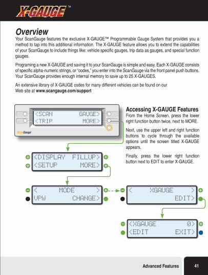
OverviewYour ScanGauge features the exclusive X-GAUGE™ Programmable Gauge System that provides you a method to tap into this additional information. The X-GAUGE feature allows you to extend the capabilities of your ScanGauge to include things like: vehicle specific gauges, trip data as gauges, and special function gauges.
Programing a new X-GAUGE and saving it to your ScanGauge is simple and easy. Each X-GAUGE consists of specific alpha-numeric strings, or “codes,” you enter into the ScanGauge via the front panel push buttons. Your ScanGauge provides enough internal memory to save up to 25 X-GAUGES.
An extensive library of X-GAUGE codes for many different vehicles can be found on our Web site at www.scangauge.com/support
Accessing X-GAUGE FeaturesFrom the Home Screen, press the lower right function button twice, next to MORE.
Next, use the upper left and right function buttons to cycle through the available options until the screen titled X-GAUGE appears.
Finally, press the lower right function button next to EDIT to enter X-GAUGE.
<SCAN
<TRIP
GAUGE>
MORE>
<SETUP
<DISPLAY
MORE>
FILLUP>
VPW
<
CHANGE>
>MODE
<EDIT
<XGAUGE
EXIT>
0>
<
EDIT>
>XGAUGE
X-GAUGE™TM
Advanced Features 41
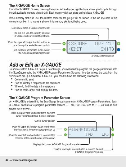
The X-GAUGE Home ScreenFrom the X-GAUGE Screen, pressing the upper left and upper right buttons allows you to cycle through the 25 available memory slots (0-24). Each memory slot can store an individual X-GAUGE.
If the memory slot is in use, the 3-letter name for the gauge will be shown in the top line next to the memory number. If no name is shown, this memory slot is not being used.
Currently selected X-GAUGE memory slot
If a slot is in use, the currently selected X-GAUGE name will be displayed here
Push the upper left or right function buttons to cycle through the available memory slots
Push the lower left function button to edit the currently selected memory slot
X-GAUGE Home Screen
<EDIT
<XGAUGE
EXIT>
AVG 21>
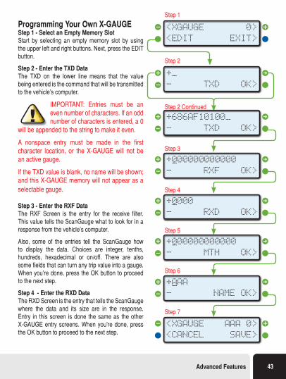
Add or Edit an X-GAUGE To add a custom X-GAUGE to your ScanGauge, you will need to program the gauge parameters into the ScanGauge using the X-GAUGE Program Parameters Screens. In order to read the data from the vehicle and set up a functional X-GAUGE, you need to have the following information:• Command to send• How to identify a response to the command• Where to find the data in the response• How to scale, offset and display the data.
The X-GAUGE Program Parameter ScreenAn X-GAUGE is entered into the ScanGauge through a series of X-GAUGE Program Parameters. Each X-GAUGE consists of 4 program parameter screens — TXD, RXF, RXD and MTH — as well as one gauge name screen.
Press the upper right function button to move the cursor forward and move the next character
Displays the current X-GAUGE Program Parameter
Press the lower right function button to move to the next X-GAUGE Program Parameter
Current cursor position
Push the upper left function button to increment the character at the current cursor position up
Push the lower left function button to increment the character at the current cursor position down
-
+686AF10100_
OK>TXD
»
42 — www.ScanGauge.com
Programming Your Own X-GAUGEStep 1 - Select an Empty Memory SlotStart by selecting an empty memory slot by using the upper left and right buttons. Next, press the EDIT button.
Step 2 - Enter the TXD DataThe TXD on the lower line means that the value being entered is the command that will be transmitted to the vehicle’s computer.
IMPORTANT: Entries must be an even number of characters. If an odd number of characters is entered, a 0
will be appended to the string to make it even.
A nonspace entry must be made in the first character location, or the X-GAUGE will not be an active gauge.
If the TXD value is blank, no name will be shown; and this X-GAUGE memory will not appear as a selectable gauge.
Step 3 - Enter the RXF DataThe RXF Screen is the entry for the receive filter. This value tells the ScanGauge what to look for in a response from the vehicle’s computer.
Also, some of the entries tell the ScanGauge how to display the data. Choices are integer, tenths, hundreds, hexadecimal or on/off. There are also some fields that can turn any trip value into a gauge. When you’re done, press the OK button to proceed to the next step.
Step 4 - Enter the RXD DataThe RXD Screen is the entry that tells the ScanGauge where the data and its size are in the response. Entry in this screen is done the same as the other X-GAUGE entry screens. When you’re done, press the OK button to proceed to the next step.
Step 1
Step 2
Step 2 Continued
Step 3
Step 4
Step 5
Step 6
Step 7
<EDIT
<XGAUGE
EXIT>
0>
-
+_
OK>
»
TXD
»
-
+686AF10100_
OK>TXD
»
-
+000000000000_OK>RXF
»
-
+0000
OK>RXD
»_
-
+000000000000
OK>MTH
»_
-
+AAA
OK>NAME
»_
<CANCEL
<XGAUGE
SAVE>
AAA 0>
Advanced Features 43
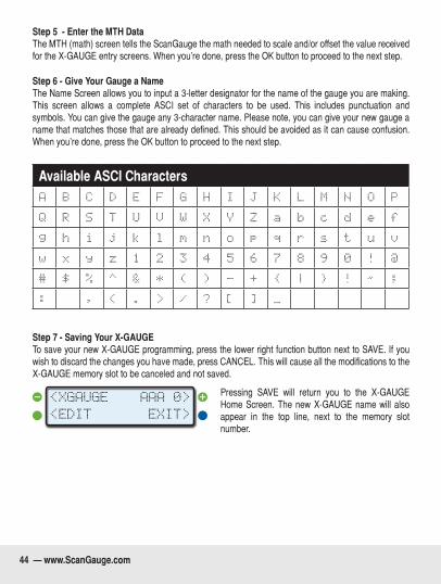
Step 5 - Enter the MTH Data The MTH (math) screen tells the ScanGauge the math needed to scale and/or offset the value received for the X-GAUGE entry screens. When you’re done, press the OK button to proceed to the next step.
Step 6 - Give Your Gauge a NameThe Name Screen allows you to input a 3-letter designator for the name of the gauge you are making. This screen allows a complete ASCI set of characters to be used. This includes punctuation and symbols. You can give the gauge any 3-character name. Please note, you can give your new gauge a name that matches those that are already defined. This should be avoided as it can cause confusion. When you’re done, press the OK button to proceed to the next step.
Available ASCI CharactersA B C D E F G H I J K L M N O P
Q R S T U V W X Y Z a b c d e f
g h i j k l m n o p q r s t u v
w x y z 1 2 3 4 5 6 7 8 9 0 ! @
# $ % ^ & * ( ) - + { | } ! ~ ;
: ‘ , < . > / ? [ ] _ « °
Step 7 - Saving Your X-GAUGETo save your new X-GAUGE programming, press the lower right function button next to SAVE. If you wish to discard the changes you have made, press CANCEL. This will cause all the modifications to the X-GAUGE memory slot to be canceled and not saved.
Pressing SAVE will return you to the X-GAUGE Home Screen. The new X-GAUGE name will also appear in the top line, next to the memory slot number.
<EDIT
<XGAUGE
EXIT>
AAA 0>
44 — www.ScanGauge.com
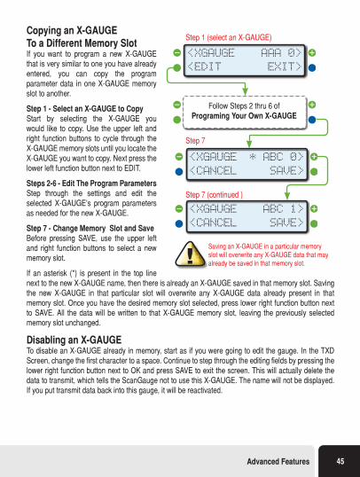
Copying an X-GAUGE To a Different Memory SlotIf you want to program a new X-GAUGE that is very similar to one you have already entered, you can copy the program parameter data in one X-GAUGE memory slot to another.
Step 1 - Select an X-GAUGE to Copy Start by selecting the X-GAUGE you would like to copy. Use the upper left and right function buttons to cycle through the X-GAUGE memory slots until you locate the X-GAUGE you want to copy. Next press the lower left function button next to EDIT.
Steps 2-6 - Edit The Program ParametersStep through the settings and edit the selected X-GAUGE’s program parameters as needed for the new X-GAUGE.
Step 7 - Change Memory Slot and Save Before pressing SAVE, use the upper left and right function buttons to select a new memory slot.
If an asterisk (*) is present in the top line next to the new X-GAUGE name, then there is already an X-GAUGE saved in that memory slot. Saving the new X-GAUGE in that particular slot will overwrite any X-GAUGE data already present in that memory slot. Once you have the desired memory slot selected, press lower right function button next to SAVE. All the data will be written to that X-GAUGE memory slot, leaving the previously selected memory slot unchanged.
Disabling an X-GAUGETo disable an X-GAUGE already in memory, start as if you were going to edit the gauge. In the TXD Screen, change the first character to a space. Continue to step through the editing fields by pressing the lower right function button next to OK and press SAVE to exit the screen. This will actually delete the data to transmit, which tells the ScanGauge not to use this X-GAUGE. The name will not be displayed. If you put transmit data back into this gauge, it will be reactivated.
<EDIT
<XGAUGE
EXIT>
1>
Step 1 (select an X-GAUGE)
Step 7
Step 7 (continued )
<EDIT
<XGAUGE
EXIT>
AAA 0>
<CANCEL
<XGAUGE
SAVE>
* ABC 0>
<CANCEL
<XGAUGE
SAVE>
ABC 1>
Follow Steps 2 thru 6 of Programing Your Own X-GAUGE
Saving an X-GAUGE in a particular memory slot will overwrite any X-GAUGE data that may already be saved in that memory slot.
Advanced Features 45
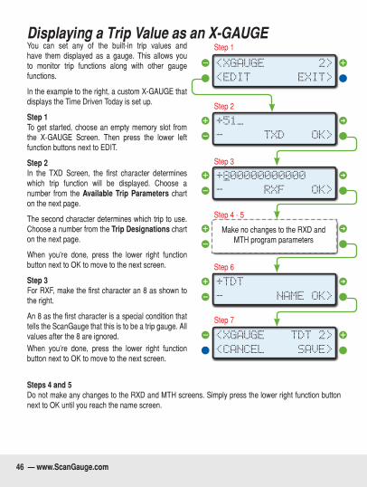
Displaying a Trip Value as an X-GAUGEYou can set any of the built-in trip values and have them displayed as a gauge. This allows you to monitor trip functions along with other gauge functions.
In the example to the right, a custom X-GAUGE that displays the Time Driven Today is set up.
Step 1To get started, choose an empty memory slot from the X-GAUGE Screen. Then press the lower left function buttons next to EDIT.
Step 2In the TXD Screen, the first character determines which trip function will be displayed. Choose a number from the Available Trip Parameters chart on the next page.
The second character determines which trip to use. Choose a number from the Trip Designations chart on the next page.
When you’re done, press the lower right function button next to OK to move to the next screen.
Step 3For RXF, make the first character an 8 as shown to the right.
An 8 as the first character is a special condition that tells the ScanGauge that this is to be a trip gauge. All values after the 8 are ignored. When you’re done, press the lower right function button next to OK to move to the next screen.
Steps 4 and 5Do not make any changes to the RXD and MTH screens. Simply press the lower right function button next to OK until you reach the name screen.
Step 1
Step 2
Step 3
Step 4 - 5
Step 6
Step 7
<EDIT
<XGAUGE
EXIT>
2>
-
+51_
OK>TXD
»
-
+800000000000_OK>RXF
»
-
+0000
OK>RXD
»_
-
+TDT
OK>NAME
»
<CANCEL
<XGAUGE
SAVE>
TDT 2>
Make no changes to the RXD and MTH program parameters
46 — www.ScanGauge.com
Step 6Enter a name for your new X-GAUGE. For this example, we used TDT for Time Driven Today. When you’re done, press the lower right function button next to OK, to move to the next screen.
Step 7To complete this X-GAUGE, press lower right function button next to SAVE. Once saved, the new X-GAUGE will be available on the GAUGE screen along with other gauges (see page 25).
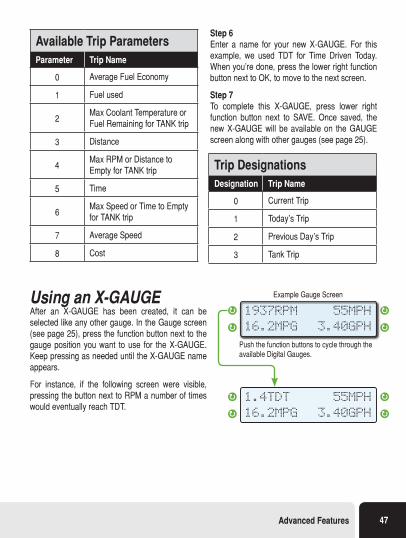
Using an X-GAUGEAfter an X-GAUGE has been created, it can be selected like any other gauge. In the Gauge screen (see page 25), press the function button next to the gauge position you want to use for the X-GAUGE. Keep pressing as needed until the X-GAUGE name appears.
For instance, if the following screen were visible, pressing the button next to RPM a number of times would eventually reach TDT.
Push the function buttons to cycle through the available Digital Gauges.
Example Gauge Screen
1937RPM
16.2MPG
55MPH
3.40GPH
1.4TDT
16.2MPG
55MPH
3.40GPH
Available Trip ParametersParameter Trip Name
0 Average Fuel Economy
1 Fuel used
2Max Coolant Temperature or Fuel Remaining for TANK trip
3 Distance
4Max RPM or Distance to Empty for TANK trip
5 Time
6Max Speed or Time to Empty for TANK trip
7 Average Speed
8 Cost
Trip DesignationsDesignation Trip Name
0 Current Trip
1 Today’s Trip
2 Previous Day’s Trip
3 Tank Trip
Advanced Features 47
Performance Monitor
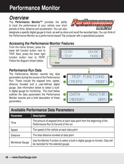
OverviewThe Performance Monitor™ provides the ability to track the performance of your vehicle over short periods of time, distance and acceleration. You can also designate a specific digital gauge to track, as well as store and recall the recorded data. You can think of the Performance Monitor as a performance-based Trip computer with a specialized purpose.
Accessing the Performance Monitor FeaturesFrom the Home Screen, press the lower left function button next to TRIP. Next, press the lower right function button next to PERF. Follow the diagram shown below.
Performance Run DataThe Performance Monitor records key data parameters during the course of the Performance Run. These include the elapsed time, speed, distance traveled and a user-defined digital gauge. See information below to select a built-in digital gauge for monitoring. The chart below outlines the data parameters the Performance Monitor records and a brief description of these parameters.
Available Performance Data ParametersParameter Description
TimeThe amount of elapsed time at each data point from the beginning of the Performance Run to the end of the run
Speed The speed of the vehicle at each data point
Distance The total distance traveled at data point
Monitored GaugeUse the Monitor Function to select a built-in digital gauge to monitor. Data will be recorded for the selected gauge.
TM
<SCAN
<TRIP
GAUGE>
MORE>
<TRIPS PERF>
TRIP FUNCTIONS
<DATA MONITOR>
<MEMORY ARM>
48 — www.ScanGauge.com
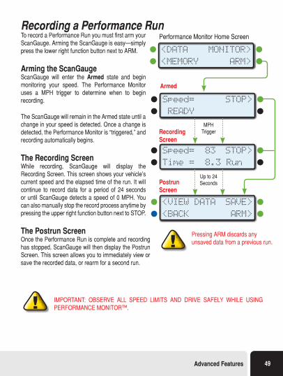
Recording a Performance RunTo record a Performance Run you must first arm your ScanGauge. Arming the ScanGauge is easy—simply press the lower right function button next to ARM.
Arming the ScanGaugeScanGauge will enter the Armed state and begin monitoring your speed. The Performance Monitor uses a MPH trigger to determine when to begin recording.
The ScanGauge will remain in the Armed state until a change in your speed is detected. Once a change is detected, the Performance Monitor is “triggered,” and recording automatically begins.
The Recording ScreenWhile recording, ScanGauge will display the Recording Screen. This screen shows your vehicle’s current speed and the elapsed time of the run. It will continue to record data for a period of 24 seconds or until ScanGauge detects a speed of 0 MPH. You can also manually stop the record process anytime by pressing the upper right function button next to STOP.
The Postrun ScreenOnce the Performance Run is complete and recording has stopped, ScanGauge will then display the Postrun Screen. This screen allows you to immediately view or save the recorded data, or rearm for a second run.
IMPORTANT: OBSERVE ALL SPEED LIMITS AND DRIVE SAFELY WHILE USING PERFORMANCE MONITOR™.
<DATA MONITOR>
<MEMORY ARM>
Speed= STOP>
READY
Speed= 83 STOP>
Time = 8.3 Run
MPH Trigger
Up to 24 Seconds
<VIEW DATA SAVE>
<BACK ARM>
Performance Monitor Home Screen
Armed
Recording Screen
Postrun Screen
Pressing ARM discards any unsaved data from a previous run.
Advanced Features 49
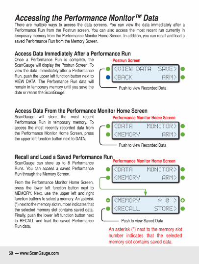
Accessing the Performance Monitor™ DataThere are multiple ways to access the data screens. You can view the data immediately after a Performance Run from the Postrun screen. You can also access the most recent run currently in temporary memory from the Performance Monitor Home Screen. In addition, you can recall and load a saved Performance Run from the Memory Screen.
Access Data Immediately After a Performance RunOnce a Performance Run is complete, the ScanGauge will display the Postrun Screen. To view the data immediately after a Performance Run, push the upper left function button next to VIEW DATA. The Performance Run data will remain in temporary memory until you save the date or rearm the ScanGauge.
Access Data From the Performance Monitor Home ScreenScanGauge will store the most recent Performance Run in temporary memory. To access the most recently recorded data from the Performance Monitor Home Screen, press the upper left function button next to DATA.
Recall and Load a Saved Performance RunScanGauge can store up to 8 Performance Runs. You can access a saved Performance Run through the Memory Screen.
From the Performance Monitor Home Screen, press the lower left function button next to MEMORY. Next, use the upper left and right function buttons to select a memory. An asterisk (*) next to the memory slot number indicates that the selected memory slot contains saved data. Finally, push the lower left function button next to RECALL and load the saved Performance Run data.
<VIEW DATA SAVE>
<BACK ARM>
Postrun Screen
Push to view Recorded Data
<DATA MONITOR>
<MEMORY ARM>
Performance Monitor Home Screen
Push to view Recorded Data
Push to view Saved Data
An asterisk (*) next to the memory slot number indicates that the selected memory slot contains saved data.
<DATA MONITOR>
<MEMORY ARM>
Performance Monitor Home Screen
<MEMORY * 0 >
<RECALL STORE>
50 — www.ScanGauge.com
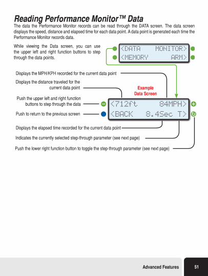
Reading Performance Monitor™ DataThe data the Performance Monitor records can be read through the DATA screen. The data screen displays the speed, distance and elapsed time for each data point. A data point is generated each time the Performance Monitor records data.
While viewing the Data screen, you can use the upper left and right function buttons to step through the data points.
<712ft 84MPH>
<BACK 8.4Sec T>
Example Data Screen
Push the upper left and right function buttons to step through the data
Push to return to the previous screen
Displays the elapsed time recorded for the current data point
Indicates the currently selected step-through parameter (see next page)
Push the lower right function button to toggle the step-through parameter (see next page)
Displays the MPH/KPH recorded for the current data point
Displays the distance traveled for the current data point
<DATA MONITOR>
<MEMORY ARM>
Advanced Features 51
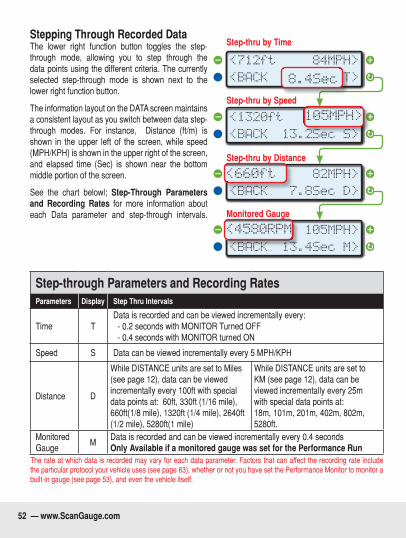
Stepping Through Recorded DataThe lower right function button toggles the step-through mode, allowing you to step through the data points using the different criteria. The currently selected step-through mode is shown next to the lower right function button.
The information layout on the DATA screen maintains a consistent layout as you switch between data step-through modes. For instance, Distance (ft/m) is shown in the upper left of the screen, while speed (MPH/KPH) is shown in the upper right of the screen, and elapsed time (Sec) is shown near the bottom middle portion of the screen.
See the chart belowl; Step-Through Parameters and Recording Rates for more information about each Data parameter and step-through intervals.
Step-through Parameters and Recording RatesParameters Display Step Thru Intervals
Time TData is recorded and can be viewed incrementally every: - 0.2 seconds with MONITOR Turned OFF - 0.4 seconds with MONITOR turned ON
Speed S Data can be viewed incrementally every 5 MPH/KPH
Distance D
While DISTANCE units are set to Miles (see page 12), data can be viewed incrementally every 100ft with special data points at: 60ft, 330ft (1/16 mile), 660ft(1/8 mile), 1320ft (1/4 mile), 2640ft (1/2 mile), 5280ft(1 mile)
While DISTANCE units are set to KM (see page 12), data can be viewed incrementally every 25m with special data points at: 18m, 101m, 201m, 402m, 802m, 5280ft.
Monitored Gauge
MData is recorded and can be viewed incrementally every 0.4 secondsOnly Available if a monitored gauge was set for the Performance Run
The rate at which data is recorded may vary for each data parameter. Factors that can affect the recording rate include the particular protocol your vehicle uses (see page 63), whether or not you have set the Performance Monitor to monitor a built-in gauge (see page 53), and even the vehicle itself.
Step-thru by Time
Step-thru by Speed
Step-thru by Distance
Monitored Gauge
<660ft 82MPH>
<BACK 7.8Sec D>
<4580RPM 105MPH>
<BACK 13.4Sec M>
<1320ft 105MPH>
<BACK 13.2Sec S>
<712ft 84MPH>
<BACK 8.4Sec T>
<712ft 84MPH>
<BACK 8.4Sec T>
<1320ft 105MPH>
<BACK 13.2Sec S>
<660ft 82MPH>
<BACK 7.8Sec D>
<4580RPM 105MPH>
<BACK 13.4Sec M>
52 — www.ScanGauge.com
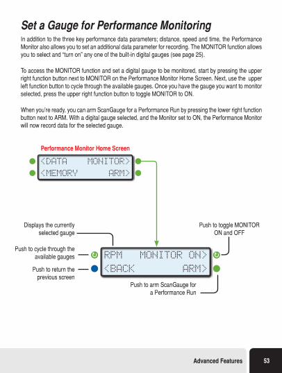
Set a Gauge for Performance MonitoringIn addition to the three key performance data parameters; distance, speed and time, the Performance Monitor also allows you to set an additional data parameter for recording. The MONITOR function allows you to select and “turn on” any one of the built-in digital gauges (see page 25).
To access the MONITOR function and set a digital gauge to be monitored, start by pressing the upper right function button next to MONITOR on the Performance Monitor Home Screen. Next, use the upper left function button to cycle through the available gauges. Once you have the gauge you want to monitor selected, press the upper right function button to toggle MONITOR to ON.
When you’re ready, you can arm ScanGauge for a Performance Run by pressing the lower right function button next to ARM. With a digital gauge selected, and the Monitor set to ON, the Performance Monitor will now record data for the selected gauge.
Displays the currently selected gauge
Push to arm ScanGauge for a Performance Run
Push to toggle MONITOR ON and OFF
Push to cycle through the available gauges
Push to return the previous screen
RPM MONITOR ON>
<BACK ARM>
Performance Monitor Home Screen
<DATA MONITOR>
<MEMORY ARM>
Advanced Features 53
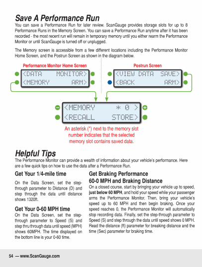
Save A Performance RunYou can save a Performance Run for later review. ScanGauge provides storage slots for up to 8 Performance Runs in the Memory Screen. You can save a Performance Run anytime after it has been recorded - the most recent run will remain in temporary memory until you either rearm the Performance Monitor or until ScanGauge is turned off or unplugged.
The Memory screen is accessible from a few different locations including the Performance Monitor Home Screen, and the Postrun Screen as shown in the diagram below.
<MEMORY * 0 >
<RECALL STORE>
Performance Monitor Home Screen Postrun Screen
<DATA MONITOR>
<MEMORY ARM>
<VIEW DATA SAVE>
<BACK ARM>
An asterisk (*) next to the memory slot number indicates that the selected memory slot contains saved data.
Helpful TipsThe Performance Monitor can provide a wealth of information about your vehicle’s performance. Here are a few quick tips on how to use the data after a Performance Run.
Get Your 1/4-mile timeOn the Data Screen, set the step-through parameter to Distance (D) and step through the data until distance shows 1320ft.
Get Your 0-60 MPH timeOn the Data Screen, set the step-through parameter to Speed (S) and step thru through data until speed (MPH) shows 60MPH. The time displayed on the bottom line is your 0-60 time.
Get Braking Performance 60-0 MPH and Braking DistanceOn a closed course, start by bringing your vehicle up to speed , just below 60 MPH, and hold your speed while your passenger arms the Performance Monitor. Then, bring your vehicle’s speed up to 60 MPH and then begin braking. Once your speed reaches 0, the Performance Monitor will automatically stop recording data. Finally, set the step-through parameter to Speed (S) and step through the data until speed shows 0 MPH. Read the distance (ft) parameter for breaking distance and the time (Sec) parameter for braking time.
54 — www.ScanGauge.com
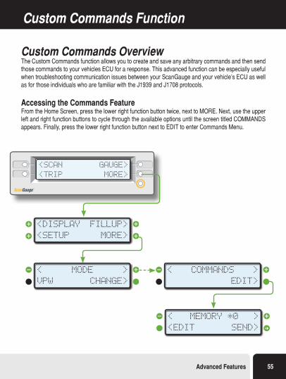
Custom Commands Function
Custom Commands OverviewThe Custom Commands function allows you to create and save any arbitrary commands and then send those commands to your vehicles ECU for a response. This advanced function can be especially useful when troubleshooting communication issues between your ScanGauge and your vehicle’s ECU as well as for those individuals who are familiar with the J1939 and J1708 protocols.
Accessing the Commands FeatureFrom the Home Screen, press the lower right function button twice, next to MORE. Next, use the upper left and right function buttons to cycle through the available options until the screen titled COMMANDS appears. Finally, press the lower right function button next to EDIT to enter Commands Menu.
<SCAN
<TRIP
GAUGE>
MORE>
<SETUP
<DISPLAY
MORE>
FILLUP>
VPW
<
CHANGE>
>MODE
<EDIT
<
SEND>
>MEMORY *0
<
EDIT>
>COMMANDS
Advanced Features 55
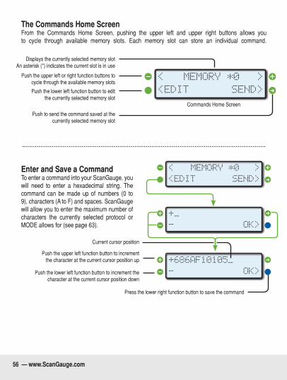
The Commands Home Screen From the Commands Home Screen, pushing the upper left and upper right buttons allows you to cycle through available memory slots. Each memory slot can store an individual command.
Push to send the command saved at the currently selected memory slot
Displays the currently selected memory slot An asterisk (*) indicates the current slot is in use
Push the upper left or right function buttons to cycle through the available memory slots
Push the lower left function button to edit the currently selected memory slot
Commands Home Screen
<EDIT
<
SEND>
>MEMORY *0
Enter and Save a CommandTo enter a command into your ScanGauge, you will need to enter a hexadecimal string. The command can be made up of numbers (0 to 9), characters (A to F) and spaces. ScanGauge will allow you to enter the maximum number of characters the currently selected protocol or MODE allows for (see page 63).
Press the lower right function button to save the command
-
+686AF10105_
OK>
»
-
+_
OK>
»
<EDIT
<
SEND>
>MEMORY *0
Current cursor position
Push the upper left function button to increment the character at the current cursor position up
Push the lower left function button to increment the character at the current cursor position down
56 — www.ScanGauge.com
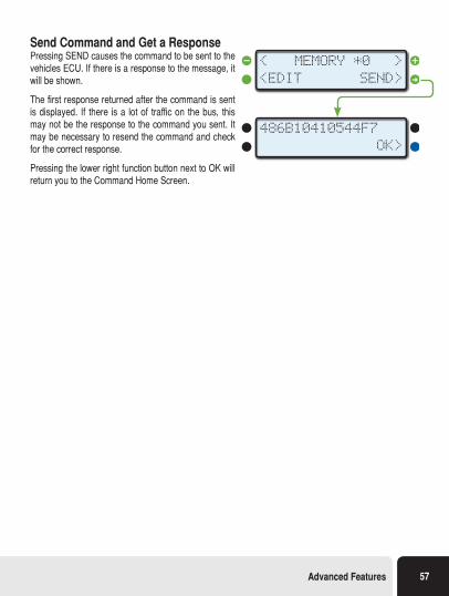
Send Command and Get a ResponsePressing SEND causes the command to be sent to the vehicles ECU. If there is a response to the message, it will be shown.
The first response returned after the command is sent is displayed. If there is a lot of traffic on the bus, this may not be the response to the command you sent. It may be necessary to resend the command and check for the correct response.
Pressing the lower right function button next to OK will return you to the Command Home Screen.
486B10410544F7
OK>
<EDIT
<
SEND>
>MEMORY *0
Advanced Features 57
TroubleshootingThis section provides basic troubleshooting information. For more comprehensive information, please visit us online at: www.ScanGauge.com/support.
Basic Troubleshooting 59
View Firmware Version 61
Reset Your ScanGauge 62
Read or Set the Operating Mode 63
58 — www.ScanGauge.com
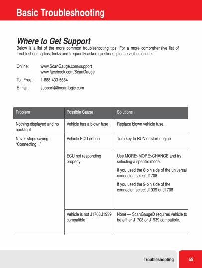
Basic Troubleshooting
Problem Possible Cause Solutions
Nothing displayed and no backlight
Vehicle has a blown fuse Replace blown vehicle fuse.
Never stops saying “Connecting...”
Vehicle ECU not on Turn key to RUN or start engine
ECU not responding properly
Use MORE>MORE>CHANGE and try selecting a specific mode.
If you used the 6-pin side of the universal connector, select J1708
If you used the 9-pin side of the connector, select J1939 or J1708
Vehicle is not J1708/J1939 compatible
None — ScanGaugeD requires vehicle to be either J1708 or J1939 compatible.
Where to Get SupportBelow is a list of the more common troubleshooting tips. For a more comprehensive list of troubleshooting tips, tricks and frequently asked questions, please visit us online.
Online: www.ScanGauge.com/support www.facebook.com/ScanGauge
Toll Free: 1-888-433-5664
E-mail: [email protected]
Troubleshooting 59
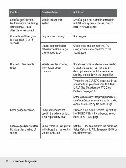
Problem Possible Cause Solutions
ScanGauge Connects, but then begins displaying erratic behavior and attempts to re-connect
Vehicle is a 28 volts system
ScanGauge is not currently compatible with 28 volts systems. Please contact support for assistance.
Connects and then goes to sleep after 10 to 15 seconds
Engine is not running Start engine.
Loss of communication between the ScanGauge and vehicles ECU
Check cable and connections. Try using an alternate connector on the ScanGauge
Unable to clear trouble codes
Vehicle is not responding to the Clear Codes command
Sometimes multiple attempts are needed to clear the codes. You may also try clearing the codes with the vehicle not running, and the key in the on position.
Try setting the CLR DTC parameter in the Advanced Setup options from NORMAL to ALT. See Set Alternate DTC Clear Methods on page 19.
Some vehicles don’t respond properly to the Clear Codes command and the codes cannot be cleared by the ScanGauge.
Some gauges are blank Some sensors are not used in the vehicle or data is not reported by ECU
If Speed is not being reported, try setting the SPEED PGN in the advanced setup menu to ALT. See page 17.
ScanGauge does not store trip data after shutting off vehicle
Some vehicles cut power to the buss the moment the vehicle is shut off
Set the TRIPS parameter in the Advanced Setup Options to AB. See page 18-19 for more information.
60 — www.ScanGauge.com
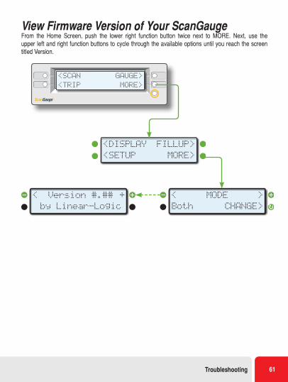
View Firmware Version of Your ScanGaugeFrom the Home Screen, push the lower right function button twice next to MORE. Next, use the upper left and right function buttons to cycle through the available options until you reach the screen titled Version.
<SCAN
<TRIP
GAUGE>
MORE>
<SETUP
<DISPLAY
MORE>
FILLUP>
Both
<
CHANGE>
>MODE
by Linear-Logic
Version #.##< +
Troubleshooting 61
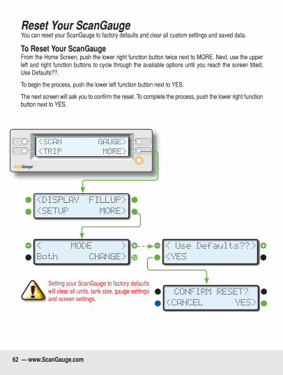
Reset Your ScanGaugeYou can reset your ScanGauge to factory defaults and clear all custom settings and saved data.
To Reset Your ScanGaugeFrom the Home Screen, push the lower right function button twice next to MORE. Next, use the upper left and right function buttons to cycle through the available options until you reach the screen titled; Use Defaults??.
To begin the process, push the lower left function button next to YES.
The next screen will ask you to confirm the reset. To complete the process, push the lower right function button next to YES.
<SCAN
<TRIP
GAUGE>
MORE>
<SETUP
<DISPLAY
MORE>
FILLUP>
Both
<
CHANGE>
>MODE
<CANCEL
CONFIRM RESET?
YES>
<YES
Use Defaults??
< >
Setting your ScanGauge to factory defaults will clear all units, tank size, gauge settings and screen settings.
62 — www.ScanGauge.com
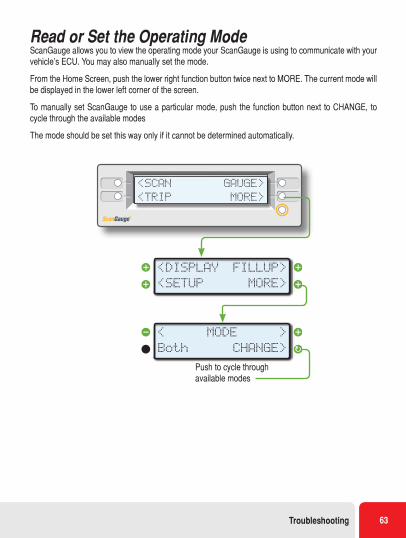
Read or Set the Operating ModeScanGauge allows you to view the operating mode your ScanGauge is using to communicate with your vehicle’s ECU. You may also manually set the mode.
From the Home Screen, push the lower right function button twice next to MORE. The current mode will be displayed in the lower left corner of the screen.
To manually set ScanGauge to use a particular mode, push the function button next to CHANGE, to cycle through the available modes
The mode should be set this way only if it cannot be determined automatically.
<SCAN
<TRIP
GAUGE>
MORE>
<SETUP
<DISPLAY
MORE>
FILLUP>
Both
<
CHANGE>
>MODE
Push to cycle through available modes
Troubleshooting 63

www.ScanGauge.com Version 6.2 SGII-UM-602
Limited Warranty Linear Logic will repair this product with new or rebuilt parts, free of charge, for a period of 3 years from the date of original purchase in the event of a defect in materials or workmanship.
Warranty Service can be obtained by sending the product to:
Linear Logic LLCATTN: Warranty Service2222 S Dobson Rd Suite 800Mesa, AZ 85202
Include your name, address, telephone number and/or e-mail address along with a copy of the Receipt or Packing List.
Also include information about the problem, including the type of vehicle you are using it on and a description of the problem.
An e-mail to [email protected] may be able to assist in solving a problem and will not diminish your rights to the full warranty.
Limits and Exclusions:
There are no express warranties except as listed above.
Linear Logic SHALL NOT BE LIABLE FOR INCIDENTAL OR CONSEQUENTIAL DAMAGES RESULTING FROM THE USE OF THIS PRODUCT OR ARISING OUT OF ANY BREACH OF THIS WARRANTY. ALL EXPRESS AND IMPLIED WARRANTIES, INCLUDING THE WARRANTIES OF MERCHANTABILITY AND FITNESS FOR A PARTICULAR PURPOSE, ARE LIMITED TO THE APPLICABLE WARRANTY PERIOD.
If a problem with this product develops after the warranty period, you may contact our service department via the mail address or e-mail address listed above for a cost estimate on repairs to the unit.
If the problem is not handled to your satisfaction, contact our customer care depart-ment at [email protected].