Embed Size (px)
Citation preview

1
UserManual
UserManual Ultralight Rigid Wheelchair
70380-b.1-APEX USER MANUAL-HR
S O M E T H I N G H A D T O B E D O N E . W E D I D I T
2
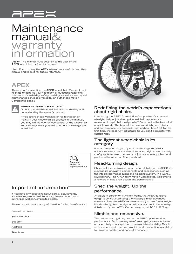
Maintenance manual&warrantyinformationDealer: This manual must be given to the user of the APEX wheelchair before its first use.
User: Prior to using the APEX wheelchair, carefully read this manual and keep it for future reference.
APEXThank you for selecting the APEX wheelchair. Please do not hesitate to send us your feedback or questions regarding this product’s reliability, safety, usability, as well as any repair/maintenance services offered by an authorized Motion
Composites dealer.
WARNING - READ THIS MANUAL
Do not operate this wheelchair without reading and
understanding this owner’s manual.
If you ignore these Warnings or fail to inspect or
maintain your wheelchair as directed in the manual,
you may fall, tip over or lose control of the wheelchair
and seriously injure yourself or others or damage the
wheelchair
Important information
If you have any questions about safety, adjustments, accessories, use, or maintenance, please contact your authorized Motion Composites dealer.
Please record the following information for future reference:
Date of purchase
Serial Number
Supplier
Address
Telephone
Redefining the world’s expectations about rigid chairs. Introducing the APEX from Motion Composites. Our newest
ultralight, fully adjustable rigid wheelchair represents a
revolution in rigid chair design. Why? Because it’s the best of all
possible worlds. The best of the celebrated lightness, strength
and performance you associate with carbon fiber. And, for the
first time, the best fully adjustable fit you don’t associate with
carbon fiber.
The lightest wheelchair in its categoryWith a transport weight of just 9.2 lb (4,2 kg), the APEX
obliterates every preconceived idea about rigid chairs. It’s fully
configurable to meet the needs of just about every client, and
performs like a carbon fiber purebred.
Head-turning design.Check out the design and construction details on the APEX. Or,
examine its innovative components and accessories, such as
the integrated impact guard and rigidizing system. In a word…
revolutionary. The APEX from Motion Composites. Welcome to
a new era in rigid chair design and performance.
Shed the weight. Up the
performance.Available in carbon or aluminum frame, the APEX cantilever
design is constructed using the industry’s most advanced
materials. Plus, the APEX represents not just low frame weight.
It’s also the lightest configured adjustable chair in the industry.
A fully configured APEX Carbon weighs just 16,5 lb (7,5 kg).
Nimble and responsive. The unique rear rigidizing bar on the APEX optimizes ride
performance. By increasing rear-frame rigidity, we’ve achieved
an open design concept that increases lateral stability. Result
— flex where and when you want it, and no sacrifice in stability
for gains in comfort and ease of transport.
European
authorized
representative :
3
UserManual
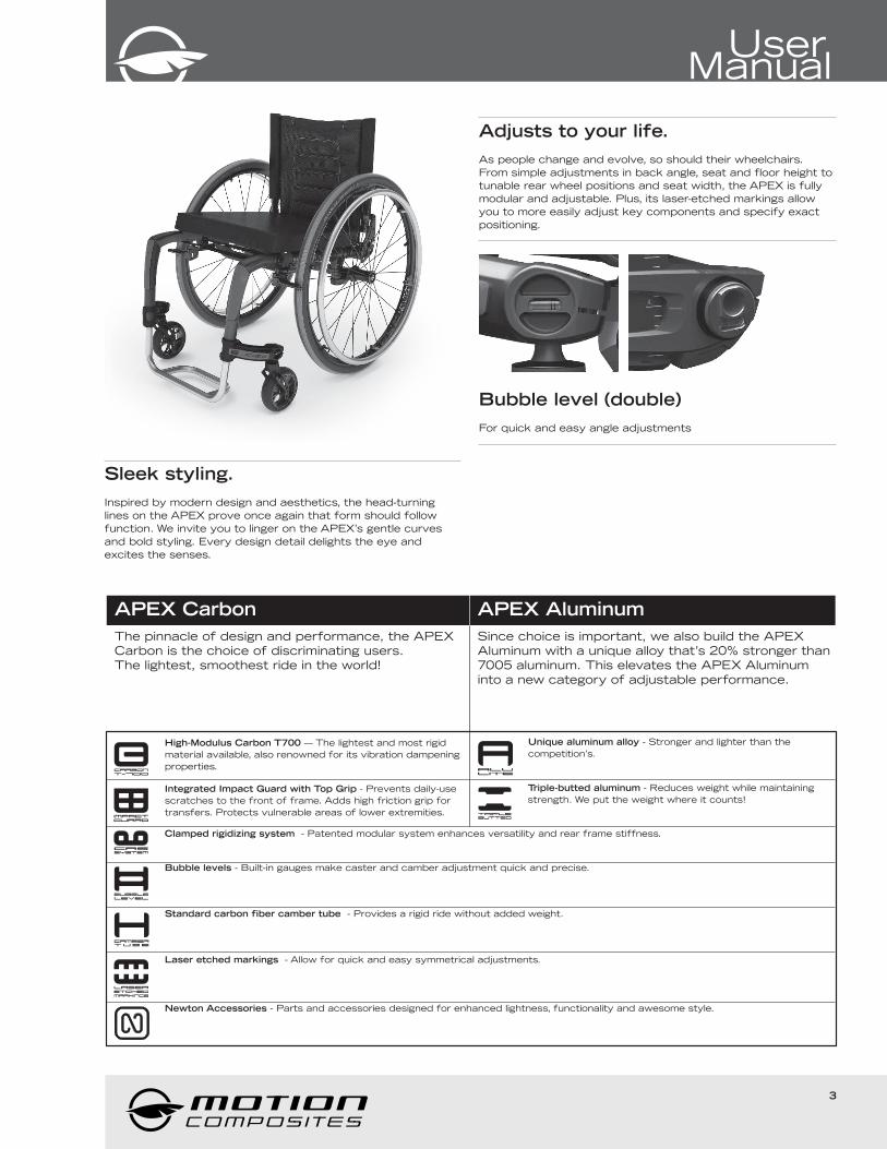
Sleek styling.
Inspired by modern design and aesthetics, the head-turning
lines on the APEX prove once again that form should follow
function. We invite you to linger on the APEX’s gentle curves
and bold styling. Every design detail delights the eye and
excites the senses.
Adjusts to your life.
As people change and evolve, so should their wheelchairs.
From simple adjustments in back angle, seat and floor height to
tunable rear wheel positions and seat width, the APEX is fully
modular and adjustable. Plus, its laser-etched markings allow
you to more easily adjust key components and specify exact
positioning.
Bubble level (double)
For quick and easy angle adjustments
APEX Carbon
The pinnacle of design and performance, the APEX
Carbon is the choice of discriminating users.
The lightest, smoothest ride in the world!
APEX Aluminum
Since choice is important, we also build the APEX
Aluminum with a unique alloy that’s 20% stronger than
7005 aluminum. This elevates the APEX Aluminum
into a new category of adjustable performance.
carbonT-700
High-Modulus Carbon T700 — The lightest and most rigid
material available, also renowned for its vibration dampening
properties.
impactguard
Integrated Impact Guard with Top Grip - Prevents daily-use
scratches to the front of frame. Adds high friction grip for
transfers. Protects vulnerable areas of lower extremities.
aluLiTE
Unique aluminum alloy - Stronger and lighter than the
competition’s.
TRiPLEBUTTED
Triple-butted aluminum - Reduces weight while maintaining
strength. We put the weight where it counts!
CRSSYSTEM
Clamped rigidizing system - Patented modular system enhances versatility and rear frame stiffness.
BUBBLElevel
Bubble levels - Built-in gauges make caster and camber adjustment quick and precise.
camberT U B E
Standard carbon fiber camber tube - Provides a rigid ride without added weight.
Laseretchedmarkings
Laser etched markings - Allow for quick and easy symmetrical adjustments.
Newton Accessories - Parts and accessories designed for enhanced lightness, functionality and awesome style.

4
Table of contents
WELCOME TO APEX 2
CONTACTING US
IMPORTANT INFORMATION
TABLE OF CONTENTS 4
3. PRODUCT OVERVIEW 5
PARTS LIST
4. BEFORE USE 6
4.1 GENERAL WARNING
4.1.1 SAFETY INSPECTION AND MAINTENANCE
4.1.2 MOTOR VEHICLE SAFETY
4.1.3 ACCLIMATING TO YOUR NEW WHEELCHAIR
4.1.4 NOTE TO USERS
4.1.5 IMPORTANT WARNING WHEN USING THE STROLLER-HANDLE
4.1.6 NOTE TO DEALERS & QUALIFIED TECHNICIANS
4.2 SYMBOLS 7
5. TUTORIAL
6. TECHNICAL SPECIFICATIONS 7
6.1 STRUCTURE
6.2 DIMENSIONS
6.3 ADJUSTABILITY
6.4 BACK UPHOLSTERY
6.5 LABEL LOCATIONS
7. SAFETY 8
7.1 PERIODIC CHECKLIST
7.2 WEIGHT LIMITATION
7.3 WEIGHT TRAINING AND SPORTING ACTIVITIES
8. RIDING YOUR APEX 8
8.1.1 TO REDUCE THE RISK OF ACCIDENT
8.1.2 ENVIRONMENTAL CONDITIONS
8.1.3 CAREGIVERS 9
8.2 RIDING YOUR WHEELCHAIR
8.2.0 IN ORDER TO REDUCE THE RISK OF A TIP-OVER
8.2.1 BALANCE POINT
8.2.2 WHEELIES
8.2.3 TRANSFERRING
8.2.4 GETTING DRESSED
8.2.5 REACHING/LEANING/BENDING 10
8.2.6 MOVING BACKWARDS
8.2.7 RAMPS, SLOPES & SIDE HILLS
8.2.8 OBSTACLES
8.2.9 CURBS AND STEPS 11
8.2.10 MOVING WITH ASSISTANCE
8.2.10.1 CLIMBING A CURB OR SINGLE STEP
8.2.10.2 DESCENDING A CURB OR SINGLE STEP
8.2.11 STAIRS
8.2.12 CLIMBING A FLIGHT OF STAIRS WARNING
8.2.13 DESCENDING A FLIGHT OF STAIRS WARNING 12
8.2.14 ESCALATORS
9. HOW TO USE YOUR APEX 12
9.1 FOLDING & UNFOLDING
9.1.1 FOLDING THE BACKREST
9.1.2 UNFOLDING THE BACKREST
9.2 WHEEL LOCKS
9.3 FOOTREST
9.3.1 ADJUSTING THE FOOTREST HEIGHT
9.4 FOOTPLATE OR OPEN LOOP
9.5 ARMRESTS 13
9.5.1 FLIP-BACK ARMREST
9.5.2 REMOVABLE T ARMREST
9.5.3 SWING-AWAY ARMREST
9.6 SEAT BELTS
9.6.1 AUTO BUCKLE AND AIRCRAFT BUCKLE SEATBELTS
9.6.2 VELCRO™ BELT
9.7 ANTI-TIPPERS
9.8 REAR WHEELS AXLES 14
9.8.1 QUICK-RELEASE AXLES
9.8.2 FIXED AXLES
9.9 SEAT SLINGS
9.10 PUSH HANDLES
10. ADJUSTMENTS AND MAINTENANCE OF YOUR APEX 15
10.1 SERVICE
10.2 REPLACEMENT PARTS
10.3 TOOLS NEEDED
10.4 GENERAL MAINTENANCE
10.4.1 TIRE PRESSURE
10.4.2 CLEANING YOUR WHEELCHAIR
10.4.3 STORING AND SHIPPING YOUR WHEELCHAIR
10.5 BACKREST
10.5.1 REMOVING/INSTALLING THE BACK CANES
10.5.2 ADJUSTING THE BACK ANGLE
10.5.3 REMOVING/INSTALLING THE SEAT BELT 16
10.5.4 ADJUSTING THE BACKREST HEIGHT
10.5.5 INSTALLING/REMOVING STANDARD BACK UPHOLSTERY
10.5.6 INSTALLING/REMOVING ADJUSTABLE TENSION BACK UPHOLSTERY
10.6 ARMREST 17
10.6.1 INSTALLING FLIP-BACK ARMRESTS
10.6.2 ADJUSTING THE HEIGHT OF THE ARMRESTS
10.6.3 INSTALLING REMOVABLE T-ARMRESTS AND RIGID SIDEGUARD
10.6.4 REPLACING ARMREST PAD
10.6.5 INSTALLING THE SWING-AWAY ARMREST RECEIVER
10.6.6 ADJUSTING SWING-AWAY ARMREST HEIGHT
10.7 FOOTREST LENGHT 18
10.7.1 ADJUSTING FOOTREST LENGHT
10.8 SEAT
10.8.1 REPLACING SEAT UPHOLSTERY
10.9 SEAT-TO-FLOOR HEIGHT
10.9.1 CHANGING THE FRONT SEAT-TO-FLOOR HEIGHT
10.9.2 CHANGING REAR SEAT-TO-FLOOR HEIGHT
10.9.3 CHANGING FRONT & REAR SEAT-TO-FLOOR HEIGHT
10.10 FRONT CASTERS, FORKS AND FORK STEM ASSEMBLIES
10.10.1 REMOVING/INSTALLING/REPOSITIONING THE FRONT WHEELS
10.10.2 REMOVING/INSTALLING THE CASTER HOUSING
10.10.3 ADJUSTING THE CASTER HOUSING ANGLE
10.11 REAR WHEELS 19
10.11.1 ADJUSTING QUICK-RELEASE AXLES
10.11.2 REPLACING/ADJUSTING HAND RIMS
10.11.3 ADJUSTING THE REAR AXLE HEIGHT
10.11.4 ADJUSTING REAR WHEEL SPACING
10.11.5 ADJUSTING THE TOE-IN/TOE-OUT WITH REAR WHEEL CAMBER
10.12 WHEEL LOCKS 20
10.12.1 REPLACING/ADJUSTING THE WHEEL LOCK
10.13 LOCK EXTENSIONS
10.13.1 REPLACING/ADJUSTING THE LOCK EXTENSIONS
10.14 ANTI-TIPPERS
10.14.1 ADJUSTING THE HEIGHT OF THE ANTI-TIPPERS
10.15. HEADREST KIT AND HEADREST SUPPORT
10.15.1 INSTALLING A HEADREST SUPPORT
10.15.2 INSTALLING HEADREST KIT
10.16 AMPUTEE AXLE PLATE 21
10.16.1 INSTALLING AN AMPUTEE AXLE PLATE
10.17 USING A PARATRANSIT SERVICE
11 MOTION COMPOSITES LIMITED WARRANTY 21
12 PARTICULAR DAMAGES 22
12.1 DAMAGE REQUIRING SERVICE
12.2 SPECIAL DAMAGES THAT REQUIRE THE RETURN
OF THE WHEELCHAIR TO THE MANUFACTURER
12.3 REPAIR PROCEDURE
13 SAFETY INSPECTION CHECKLIST 22
14 DECLARATION OF CONFORMITY 24
5
UserManual
216
4
13
11
9
10
7
6
12
8
15
3
5
1
14
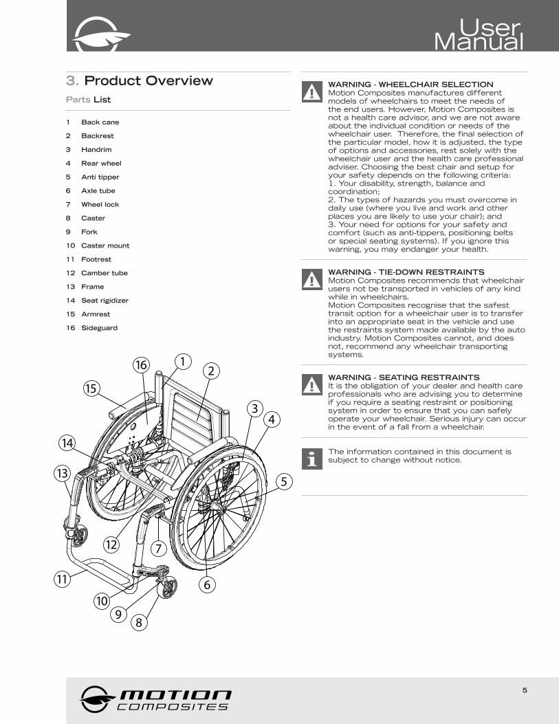
3. Product Overview
Parts List
1 Back cane
2 Backrest
3 Handrim
4 Rear wheel
5 Anti tipper
6 Axle tube
7 Wheel lock
8 Caster
9 Fork
10 Caster mount
11 Footrest
12 Camber tube
13 Frame
14 Seat rigidizer
15 Armrest
16 Sideguard
WARNING - WHEELCHAIR SELECTIONMotion Composites manufactures different models of wheelchairs to meet the needs of the end users. However, Motion Composites is not a health care advisor, and we are not aware about the individual condition or needs of the wheelchair user. Therefore, the final selection of the particular model, how it is adjusted, the type of options and accessories, rest solely with the wheelchair user and the health care professional adviser. Choosing the best chair and setup for your safety depends on the following criteria:1. Your disability, strength, balance and coordination;2. The types of hazards you must overcome in daily use (where you live and work and other places you are likely to use your chair); and3. Your need for options for your safety and comfort (such as anti-tippers, positioning belts or special seating systems). If you ignore this warning, you may endanger your health.
WARNING - TIE-DOWN RESTRAINTSMotion Composites recommends that wheelchair users not be transported in vehicles of any kind while in wheelchairs. Motion Composites recognise that the safest transit option for a wheelchair user is to transfer into an appropriate seat in the vehicle and use the restraints system made available by the auto industry. Motion Composites cannot, and does not, recommend any wheelchair transporting systems.
WARNING - SEATING RESTRAINTSIt is the obligation of your dealer and health care professionals who are advising you to determine if you require a seating restraint or positioning system in order to ensure that you can safely operate your wheelchair. Serious injury can occur in the event of a fall from a wheelchair.
The information contained in this document is subject to change without notice.
6
4. Before use
4.1 General WARNING
Your APEX wheelchair has been designed by
professionals with proper use high tech material in
mind. DO NOT TRY TO MODIFY THE FRAME BY
ANY MEANS. THE FRAME MAY BE SEVERELY
DAMAGED IN THE EVENT OF DRILLING AND
GRINDING, THUS VOIDING THE WARRANTY. Only
use Motion Composites approved and designed clamps
and accessories on your APEX wheelchair.
DO NOT use while under the influence of alcohol or medication
or drugs. This may impair your ability to operate the wheelchair.
Please consult your physician regarding the use of your
medication. The wheelchair is not intended for visually impaired
people.The user needs to be mentally and physically suitable to
drive the wheelchair.
CAUTION
Extreme temperatures
Risk of hypothermia or burns on wheelchair parts.
Some parts of the wheelchair can become extremely
hot or cold due to extreme temperatures.
Do not expose the product to any extreme
temperatures (e.g. direct sunlight, sauna, extreme cold)
in order to prevent injuries by contact with some parts
of the wheelchair.
4.1.1 Safety Inspections and Maintenance
It is important to keep your wheelchair in proper working
condition.
1. ALWAYS inspect and maintain your Motion Composites
wheelchair strictly in accordance with the instructions and
charts in Chapter 10.4 General Maintenance and Chapter 13
Safety Inspection Checklist.
2. If you detect a problem in the course of your inspections or
maintenance, ALWAYS have the chair serviced or repaired to
correct the problem before using the chair.
3. ALWAYS have your wheelchair completely inspected and
serviced by an authorized Motion Composite certified
technician at least once a year.
4. ALWAYS perform your safety inspections and any
maintenance or adjustments while the chair is unoccupied
(unless this Manual expressly states otherwise).
4.1.2 Motor Vehicle Safety WARNING
Motion Composites wheelchairs are NOT designed to
be used for seating in a motor vehicle, and the
wheelchairs DO NOT meet Federal Highway standards
for motor vehicle seating.
NEVER sit in your chair while in any type of moving vehicle
(bus, automobile, van, truck, boat, train, etc.). In an accident or
sudden stop, you may be thrown from the chair. In an accident
or sudden stop, a wheelchair seat belt will NOT prevent injuries
and may, in fact, cause injuries.
ALWAYS transfer to an approved vehicle seat before the
vehicle begins moving.
ALWAYS secure yourself in the approved vehicle seat using the
proper seating restraints (in a motor vehicle, lap/shoulder belts;
in a plane, lap belts, etc.).
NEVER transport your chair in the front seat of a vehicle.
Movements of the vehicle may cause the chair to shift and
interfere with the driver’s ability to control the vehicle.
When transporting your chair in a moving vehicle, ALWAYS
secure your chair so that it cannot roll or shift. In most cases,
stowing it in the trunk is the safest alternative.
NEVER use any chair that has been involved in a motor vehicle
accident. A wheelchair that has been involved in a motor
vehicle accident may be damaged in ways that are not readily
apparent and which could cause the chair to fail in use.
If you ignore these Warnings, you may fall, tip over or lose
control of the wheelchair and seriously injure yourself or others
or damage the wheelchair.
4.1.3 Acclimating to your new wheelchair WARNING
Each wheelchair is a unique piece of medical
equipment. Whether you are a new wheelchair user or
have years of experience, you MUST take the time to
acclimate to the wheelchair before you begin riding.
Start slowly and take the time to learn the handling,
maneuvering and ride characteristics of this chair.
4.1.4 Note to users:
The APEX wheelchair is a manually operated device intended
to be used as a means of mobility for persons restricted to a
sitting position. It is not indicated for the pediatric population.
Carefully read the instructions in this manual before using
or servicing your wheelchair. If you have any questions or
difficulties understanding the following instructions, please
contact a qualified technician; you may also wish to contact a
Motion Composites technician
4.1.5 Important WARNING when using the stroller-handle.
The stroller-handle is not designed to lift or pull the
weight of user in the wheelchair. It’s designed to push
and guide the wheelchair user.
Lifting or pulling the weight of the user in the wheelchair
could initiate the breakage of the push-handle and
cause serious injury.
4.1.6 Note to dealers & qualified technicians
Read this manual before servicing, repairing, operating
or adjusting the wheelchair. If you have any questions or
difficulties understanding the following instructions, please
contact a qualified technician; you may also wish to contact a
Motion Composites technician
7
UserManual
4.2 Symbols
The following symbols are used throughout this manual. Please
familiarize yourself with their meaning.
The warning sign indicates important information to
prevent injuries and property damage.
Useful information for the user
Initial setup of your APEX wheelchair must be done by
a qualified technician.
The latest version of this manual can be found on our
website at motioncomposites.com
Regular maintenance of your APEX will extend the life
of the wheelchair. Take your wheelchair to a qualified
technician every year for inspection and servicing.
Do not use air or electric tool, tightening should be
done manually.
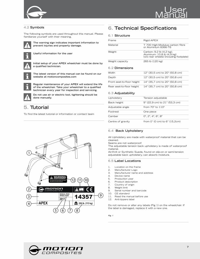
5. Tutorial
To find the latest tutorial or information or contact team
!
MAX
MANUAL RIGIDWHEELCHAIR
APEX2017
250 lb. (113 kg)
14357
2
1112
1
10
93
4
65 7 8
WARNINGAVERTISSEMENT
Do not operate with-out the anti-tipper tubes installedNe pas utiliser sans les tubes anti-basculants
6. Technical Specifications
6.1 Structure
Frame Rigid APEX
Material T 700 High-Modulus carbon fibre or Aluminium 6066-T6
Weight Carbon: 9,2 lb (4,2 kg); Aluminum: 10,8 lb (4,9 kg) (w/o rear wheels) (including footplate)
Weight capacity 265 lb (120 kg)
6.2 Dimensions
Width 12’’ (30,5 cm) to 20’’ (50,8 cm)
Depth 12’’ (30,5 cm) to 20’’ (50,8 cm)
Front seat-to-floor height 14” (35,7 cm) to 20” (50,8 cm)
Rear seat-to-floor height 14” (35,7 cm) to 20” (50,8 cm)
6.3 Adjustability
Upholstery Tension adjustable
Back height 9” (22,9 cm) to 21” (53,3 cm) Adjustable angle from 70° to 110°
Footrest One piece
Camber 0°, 2°, 4°, 6°, 8°
Centre of gravity from 0” (0 cm) to 6” (15,2cm)
6.4 Back Upholstery
All Upholstery are made with waterproof material that can be
cleaned.
Seams are not waterproof.
The adjustable tension back upholstery is made of waterproof
material.
Air-Knit or Synthetic Suede, found on slip-on or semi-tension
adjustable back upholstery, can absorb moisture.
6.5 Label Locations
1. Location on the frame
2. Manufacturer Logo
3. Manufacturer name and address
4. Device name
5. Production year
6. Product description
7. Country of origin
8. Weight limit
9. Serial number and barcode
10. CE standard
11. Read the manual before use
12. Anit-tippers label
Do not remove or alter any labels (Fig 1) on the wheelchair. If
the label is damaged, replace it with a new one.
Fig. 1
8
7. Safety
7.1 Periodic ChecklistSee related appendix (section 13).
7.2 Weight Limitation
The APEX wheelchair has a weight limit of 250 lb (113 kg).
The specified weight capacity includes: both the rider and any
luggage. A user with a 10lb backpack, for example, should not
exceed a weight of 240 lb. It is of utmost importance that
the total weight is below the above specified capacity. The
wheelchair is designed to support only one person. Please
do not stand up on the footrests. Motion Composites is not
responsible for any damages or injuries caused by the misuse
of this wheelchair.
7.3 Weight Training and Sporting Activities
This wheelchair was not designed or tested as a weight training
or stretching apparatus. Do not attempt to use this wheelchair
for weight training or stretching exercises. The warranty shall
be void if the wheelchair has been used for any weight training
or stretching purposes.
This wheelchair is not intended to be used during sporting
activities.
Should you make any adjustments, repairs or do any
servicing, ensure that all fasteners are tightly secured
before use.
Exceeding the specified weight limit could damage the
wheelchair and/or cause severe injuries.
This wheelchair was designed to be tailored to the
dimensions of its owner and as such should only be
used by its owner unless a qualified specialist,
approved by Motion Composites, has readjusted it.
8. Riding your APEX
Various adjustments of your wheelchair (seat height/
depth/system, back angle, rear & front wheels camber/
size/position, position of the front riggings) could affect
the center of gravity. The adjustments should be
performed by a professional and the wheelchair user
should be aware that the stability could be affected by
these adjustments.
DO NOT tilt the wheelchair or perform a wheelie
without assistance.
DO NOT stand on the wheelchair or part of the frame
of the wheelchair.
DO NOT sit or transfer into the wheelchair unless it is
fully open and the seat frame rails are fully seated into
the receivers.
DO NOT use the footplate as a platform when getting
in or out of the wheelchair or to reach for an object.
8.1.1 To reduce the risk of accident
We recommend that you review safe wheelchair use with your
physician prior to using this equipment.
Take the time to read the instructions in this manual to ensure
that you feel comfortable using the wheelchair without
assistance.
Always be aware of hazards. Unless you are a skilled rider of
this wheelchair and that you are sure you are not at risk to tip
over, anti-tippers SHOULD be used with your wheelchair at all
times.
Because anti-tippers are an option in some markets on this
wheelchair, Motion Composites strongly recommends to order
the anti-tippers as they are an important safeguard for the
wheelchair user.
a) Always use anti-tippers if you are not a skilled rider.
b) Always use anti-tippers each time you modify or adjust your
wheelchair. Any change may make it easier to tip backward. .
c) Use anti-tippers until you adapt to the change, and are sure
that you are not at risk to tip over.
8.1.2 Environmental Conditions
The APEX was designed to be used on hard and plane
surfaces like asphalt, concrete, and indoor hard flooring or
carpeting.
DO NOT operate on roads, streets or highways.
Beware that the maneuverability of the wheelchair is
significantly affected by different outside conditions such as
sand, mud, rain, snow and rough surfaces. If you use your
wheelchair in these conditions, it is recommended that you have
it frequently serviced.
Be careful when using your wheelchair on wet or slippery
surfaces.
Exposure to water or excessive moisture can be damaging and
may even cause the wheelchair to corrode over the long-term.
DO NOT leave your wheelchair in humid environments such as
the bathroom (e.g. while taking a shower). Store the wheelchair
in a dry and cool location. The wheel chair should be stored
away from a direct exposure to sunlight. If the wheelchair is
wet, dry all parts with a cloth before storing it.
DO NOT use your wheelchair in the shower, pool, or other
water situations.
9
UserManual
8.1.3 Caregivers
• NEVER use removable parts (e.g. armrests, footrests) to
push the wheelchair and never use them to lift the wheelchair
occupied since they could cause injuries or damage.
• Ensure that the wheelchair is equipped with push handles and
that its grips are securely in place.
• Turn anti-tipping devices upwards or remove them to avoid
tripping.
• Should you need to leave the wheelchair user unattended,
engage the wheel locks and place the anti-tipping devices
back in the downward position.
• Ask an experienced caregiver to explain safe assistance
methods to you.
• Ensure ongoing communication between you and the
wheelchair user as to avoid any kind of confusion.
• Maintain proper posture to tilt or lift the wheelchair; keep your
back straight and bend at the knees.
• Instruct the wheelchair user to lean his/her back when you are
tilting the wheelchair.
8.2 Riding your wheelchair
8.2.0 In order to reduce the risk of a tip-over, you should:
1. CONSULT your doctor, nurse or therapist to find out what
axle and caster position and other chair configuration options
are best for you.
2. CONSULT your authorized Motion Composites dealer
BEFORE you modify or adjust your wheelchair. Often, an
adjustment you wish to make can be offset by another
that you have not considered. For example, you may want
to adjust the back angle rearward, which will increase
the likelihood of a rear tip-over. You might not think you
could counteract this tendency by moving the rear wheels
backward. Your authorized Motion Composites dealer will be
able to give you expert, personalized advice in such matters.
3. ALWAYS have someone assist you until you learn your
chair’s balance points and are completely comfortable in
your ability to operate your chair under all conditions so as to
avoid tip-overs.
4. ALWAYS use anti-tippers.
If you ignore these Warnings, you may fall, tip over or lose
control of the wheelchair and seriously injure yourself or others
or damage the wheelchair.
8.2.1 Balance point
It is important to begin by learning all of the specific
characteristics of your wheelchair. Ask a health professional
to explain them to you. Carrying a backpack will affect the
balance point of your wheelchair. Be aware of resulting
handling factors in relation to your body position, posture or
weight distribution. The center of gravity is affected by the
angle of the wheelchair on a ramp or slope. This can be felt in
forward and backward as well as side to side movements.
Make sure to review the different riding techniques prior to
using the wheelchair. Use anti-tippers until you are skilled at
riding your wheelchair in any situation.
8.2.2 Wheelies
DO NOT attempt to perform a wheelie in
your wheelchair because of the dangerous
nature of this kind of maneuver. Motion
Composites recognizes that some
wheelchair users will ignore this Warning. If
you should choose to ignore this Warning,
you should follow these steps to help learn
to do a “wheelie” as safely as possible.
NEVER attempt to learn to do a wheelie without first consulting
your health care advisor. NEVER attempt to learn to do a
wheelie without an assistant that can catch you if you should
happen to start to fall. NEVER attempt to learn to do a wheelie
unless you are a skilled rider on this chair.
Motion Composites always recommend using the anti-tippers
at all-time unless they need to be removed to go up or down a
curb/step. Anti-tippers should be reinstalled once the curb/step
is cleared.
8.2.3 Transferring
Rotate the front casters forward to
enhance stability.
Place the wheelchair as close to your
transfer location as possible. Engage wheel
locks. Position yourself as far back as
possible when transferring weight to reduce
risk of tipping forward. If you have good
upper body strength, balance and agility, you may be able to
perform transfers independently.
Rotate or remove footrests if at all possible as to avoid putting
weight on them. If possible, make use of a transfer board.
Always ask a healthcare provider to learn safe transfer
methods.
Always ask a healthcare provider to learn safe transfer
methods.
For safety reason, user should always reduce to the
minimum the transfer distance.
DO NOT sit or transfer into the wheelchair unless it is fully
open and the seat frame rails are fully seated into the
receivers.
DO NOT use the footplate as a platform when getting in or out
of the wheelchair or to reach for an object.
8.2.4 Getting Dressed
When dressing or undressing on the wheelchair, rotate the front
casters forward and lock anti-tippers in the lower position.
If your wheelchair is not equipped with anti-tippers, back it
against a wall and lock the rear wheels.
10
8.2.5 Reaching/Leaning/Bending
The balance point may shift when you are putting on
clothes and/or reaching for objects while sitting in the
wheelchair.
If at all possible, use a reaching device
or ask for assistance when reaching for
objects.
Move the wheelchair as close as possible
to the required object. Rotate the casters
as far forward as possible from the rear
wheels.
NEVER reach for objects between your
legs, but rather position yourself to the side
of these objects. Do no shift your weight
sideways, but rather rise up from the seat
or move forward in the seat. Always use
both hands and grab the opposite side
wheel or armrest if you are capable of
reaching sideways. Never reach to the rear of the wheelchair
unless it is equipped with anti-tippers Never reach for objects
over the seat back: reach only as far as your arm naturally
extends without moving on the seat.
DO NOT lock the rear wheels if you are reaching backwards.
Avoid putting pressure on the footrests.
8.2.6 Moving backwards
Lock anti-tippers in lower position. Move slowly: the wheelchair
is designed to provide you with more stability when moving
forward. Look around as often as possible to avoid obstacles
in your path.
8.2.7 Ramps, Slopes & Side Hills
Ramps of 10 feet (3 meters) or less in length:
If you need to use a short ramp 10 feet (3
meters) or less, the angle of the slope should
not exceed 10 degrees, which corresponds to
a slope of 17.63%, a rise of 1.74 feet (0.53
meters) over a distance of 10 feet (3 meters).
Make sure to be assisted by a caregiver who has the physical
ability to retain the wheelchair and its occupant. The wheelchair
must always point facing up the slope.
The caregiver should always remain in the
bottom of the slope to retain the wheelchair.
Always lock the anti-tip in the safe position.
Follow the same words of caution for a hill or a
slope of 10% or less.
DO NOT use your wheelchair on a ramp under
3 meters in length if the slope angle is greater than 10 degrees
(17.63%).
Ramps of 10 feet (3 meters) or more in length:
If you must go through a slope or a vertical rise of 10 feet (3
meters) or more, the angle of the slope should not exceed 5.7
degrees, which corresponds to a 10% slope is a rise of 1 meter
for a distance of 10 meters.
Make sure to be assisted by a caregiver if you have trouble on
the slope or if the slope is between 5.7 and 10 degrees.
Try to move straight up or down the slope. Avoid turning on a
downhill slope.
Stay in the center of sidewalks and ensure that there is enough
space for the wheels.
Avoid stopping on slopes and never use the wheel locks to slow
yourself on a downhill slope. Maintain your speed by holding the
hand rims.
DO NOT ride on wet or slippery surfaces. Be cautious for
changes in terrain height or stairs at the end of a slope (front
casters may lock from simply hitting a small bump).
Ask for help should any situations arise.
Incline yourself while moving down a slope as to adjust your
center of gravity.
DO NOT use your wheelchair on your own on slopes or hill of
more than 10 feet (3 meters) in length if the angle of the slope
is greater than 5.7 degrees (10%).
8.2.8 Obstacles
Always look for obstacles or road hazards (potholes, broken
surfaces, etc.). Clear your own environment (work, home)
of any obstacles. Never use objects (furniture, ramps, and
doorknobs) to push yourself out of the wheelchair.
Lean your upper body slightly forward as you move up an
obstacle. Do the reverse while moving down an obstacle. Keep
both hands on the hand rims while passing over the obstacle.
11
UserManual
8.2.9 Curbs and Steps
Curbs and steps are extremely dangerous obstacles.
NEVER attempt to go up or down a single curb or step
without an assistant unless you are a very skilled rider
of your chair. You need to have previously learned to
safely do a wheelie in your chair and you are sure you
have the strength and balance to control your chair
during any such maneuver.
ALWAYS unlock and rotate anti-tippers up and out of
the way so they do not prevent you from executing this
maneuver.
NEVER attempt to climb or descend a curb or step
more than 4” high.
ALWAYS go straight up or down a curb or step. NEVER
climb or descend at an angle.
ALWAYS be aware that the impact of dropping down
from a curb or step can damage your chair or cause
components to become loose. If you perform such
maneuvers, inspect your chair more frequently.
ALWAYS Rotate and lock the anti-tippers back to ride
safely.
8.2.10 Moving with Assistance
Caregivers should read the “Caregiver” section of this manual.
SECTION 8.1.3
8.2.10.1 Climbing a curb or single step
1. NEVER attempt to negotiate a
curb or single step without
assistance.
2. Instruct your assistant to stand
at the rear of your wheelchair,
with the front of the wheelchair
facing the obstacle.
3. NEVER attempt to negotiate any such obstacle backward.
4. Instruct your assistant to tilt the chair up on the rear wheels
so that the front casters clear the curb or step.
5. Instruct your assistant to slowly move the chair forward and
to gently lower the casters to the upper level as soon as you
are sure that they are beyond the edge of the curb or step.
6. Instruct your assistant to continue to roll the chair forward
until the rear wheels contact the face of the curb or step.
7. Instruct your assistant to lift and roll the rear wheels up to
the upper level.
8.2.10.2 Descending a curb or single step
1. NEVER attempt to negotiate a
curb or single step without
assistance.
2. When you are still several feet or
a couple of meters from the edge
of the curb or step, instruct your
assistant to stand at the rear of
your wheelchair and turn it around so you are facing
away from the curb.
3. NEVER attempt to negotiate any curb or similar obstacle facing
forward.
4. Instruct the assistant to carefully step backwards, pulling the
wheelchair backwards, until he or she is off the curb or single
stair and standing on the lower level. The assistant should
watch his or her step over his or her shoulder when backing up
in this manner.
5. Instruct the assistant to carefully pull the wheelchair backward
until the rear wheels reach the edge of the curb or step, and to
then allow the rear wheels to slowly roll down to the lower level.
6. Instruct the assistant that, when the rear wheels are safely on
the lower level, he or she may then tilt the chair backward to the
balance point of the rear wheels, thereby raising the casters off
the upper level.
7. Instruct the assistant to slowly roll the wheelchair backward on
the rear wheels, taking small steps until the casters have cleared
the step or curb and, when clear, to gently lower the casters to
the ground at the lower level.
8.2.11 Stairs
Use an elevator wherever possible.
Ask for help from two people to move the wheelchair up or
down stairs (the caregivers should read the “Caregiver” section
of this manual).
Fasten your seat belt when being lifted in the wheelchair.
8.2.12 Climbing a flight of stairs
WARNING - DO NOT CLIMB a flight of stairs with the
user in the wheelchair.
Motion Composites recognizes that wheelchair users
may, on occasion, have no other choice and will need to
be moved up or down a flight of stairs or will need to
be lifted. Only when there is no other alternative, care
givers and wheelchair users should follow these steps
to climb a flight of stairs.
1. NEVER attempt to negotiate more than one step unless you
have two (2) able adult assistants.
2. ALWAYS position the wheelchair and user facing away from
the stairs, with one assistant at the rear (facing away from the
stairs) and one at the front of the wheelchair (facing the user).
3. The assistant at the rear of the wheelchair is in control and
know how to climb a flight of stairs. He or she must tilt the
wheelchair back to find its balance point on the rear wheels.
4. NEVER attempt to lift a wheelchair by lifting on any
removable (detachable) parts, including upholstery, removable
push handles or push handle grips.
5. ALWAYS hold the wheelchair from a solid part of the frame.
6. The second assistant at the front must firmly grip the frame
(NOT the footrest or footplate) with both hands and lift the
wheelchair up and over one stair at a time.
7. Each assistant then carefully moves up to the next stair.
8. Repeat steps 1 through 6 for each stair, until you reach the
top of the stairs.
9. When you reach the top of the stairs, the assistants should
roll the wheelchair backward on the two rear wheels until the
casters have cleared the last step, at which point the assistants
can gently lower the casters on the floor.
12
8.2.13 Descending a flight of stairs warning
DO NOT DESCEND a flight of stairs with the user in
the wheelchair.
Motion Composites recognizes that wheelchair users
may, on occasion, have no other choice and will need to
be moved up or down a flight of stairs. Only when there
is no other alternative, care givers and wheelchair users
should follow these steps to descend a flight of stairs.
1. NEVER attempt to negotiate more than one step unless you
have two (2) able adult assistants.
2. ALWAYS position the wheelchair and user facing down from
the stairs, with one assistant at the rear (facing dons from the
stairs) and one at the front of the wheelchair (facing the user).
3. The assistant at the front of the wheelchair is in control and
know how to descend a flight of stairs. The person at the rear
must tilt the wheelchair back to find its balance point on the
rear wheels.
4. NEVER attempt to lift a wheelchair by lifting on any
removable (detachable) parts, including upholstery, removable
push handles or push handle grips.
5. ALWAYS hold the wheelchair from a solid part of the frame.
6. The assistant at the front must firmly grip the frame
(NOT the footrest or footplate) with both hands and lift the
wheelchair over one stair at a time.
7. Each assistant then carefully moves down to the next stair.
8. Repeat steps 1 through 6 for each stair, until you reach the
bottom of the stairs.
9. When you reach the bottom of the stairs, the assistants
should move the wheelchair forward until the two rear wheels
clears the last step, at which point the assistants can gently
lower the casters and back wheels on the floor.
If you ignore these warnings, you may fall, tip over or lose
control of the wheelchair and seriously injure yourself or other
people and or damage the wheelchair.
8.2.14 Escalators
Under no circumstances should this wheelchair be used on an
escalator, not even with the help of an attendant. This could
cause severe injuries.
9. How to use your APEX
9.1 Folding & Unfolding
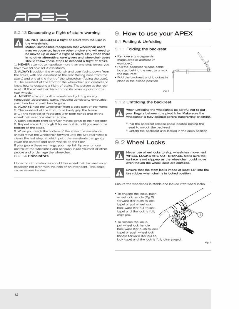
9.1.1 Folding the backrest
• Remove any sideguards,
mudguards or armrest (if
equipped)
• Pull the backrest release cable
located behind the seat to unlock
the backrest
• Fold the backrest until it lockes in
place in the closed position
Fig. 1
9.1.2 Unfolding the backrest
When unfolding the wheelchair, be careful not to put
your fingers between the pivot links. Make sure the
wheelchair is fully opened before transferring or sitting.
• Pull the backrest release cable located behind the
seat to unlock the backrest
• Unfold the backrest until locked in the open position
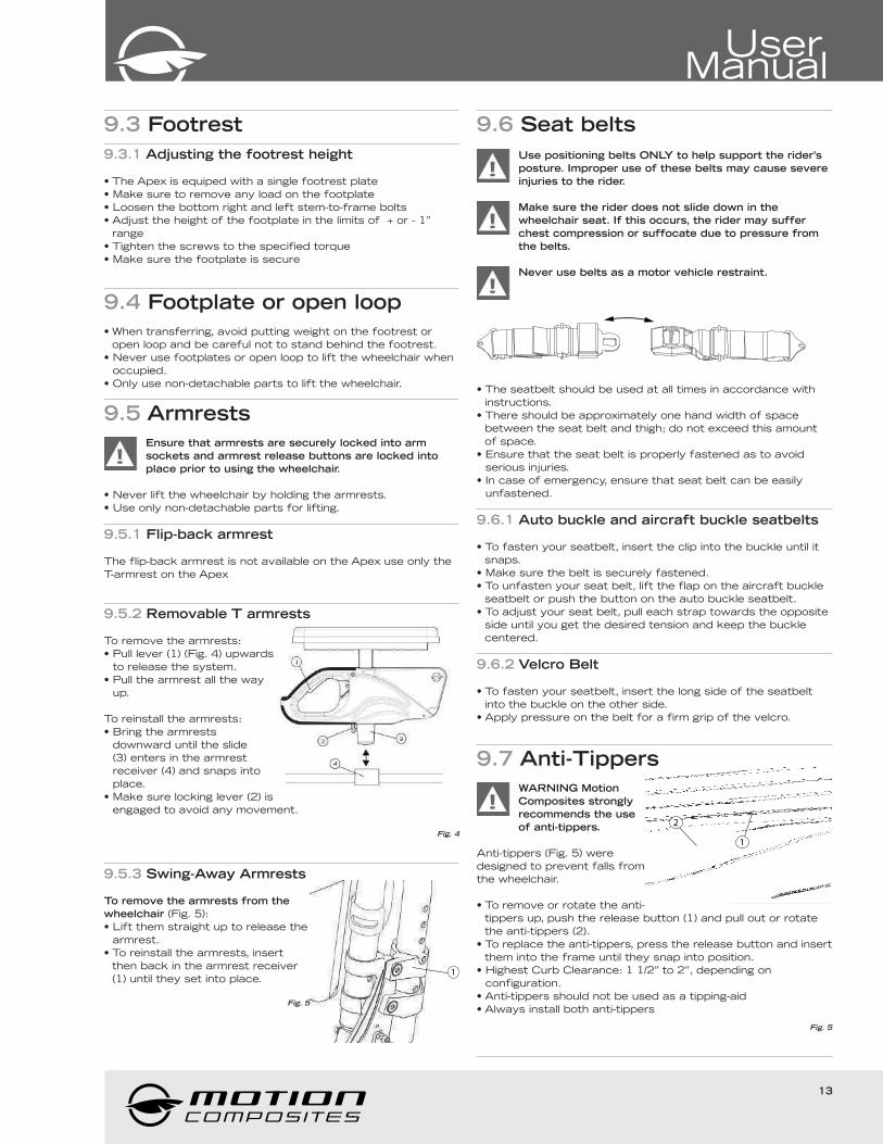
9.2 Wheel Locks
Never use wheel locks to stop wheelchair movement.
WHEEL LOCKS ARE NOT BRAKES. Make sure the
surface is not slippery as the wheelchair could move
even though the wheel locks are engaged.
Ensure that the stem locks imbed at least 1/8” into the
tire rubber when chair is in locked position.
Ensure the wheelchair is stable and locked with wheel locks.
1
• To engage the locks, push
wheel lock handle (Fig.2)
forward (for push-to-lock
type) or pull wheel lock
backward (for pull-to-lock
type) until the lock is fully
engaged.
• To release the locks,
pull wheel lock handle
backward (for push-to-lock
type) or push wheel lock
handle forward (for pull-to-
lock type) until the lock is fully disengaged.Fig. 2
13
UserManual
9.3 Footrest
9.3.1 Adjusting the footrest height
• The Apex is equiped with a single footrest plate
• Make sure to remove any load on the footplate
• Loosen the bottom right and left stem-to-frame bolts
• Adjust the height of the footplate in the limits of + or - 1’’
range
• Tighten the screws to the specified torque
• Make sure the footplate is secure
9.4 Footplate or open loop
• When transferring, avoid putting weight on the footrest or
open loop and be careful not to stand behind the footrest.
• Never use footplates or open loop to lift the wheelchair when
occupied.
• Only use non-detachable parts to lift the wheelchair.
9.5 Armrests
Ensure that armrests are securely locked into arm
sockets and armrest release buttons are locked into
place prior to using the wheelchair.
• Never lift the wheelchair by holding the armrests.
• Use only non-detachable parts for lifting.
9.5.1 Flip-back armrest
The flip-back armrest is not available on the Apex use only the
T-armrest on the Apex
9.5.2 Removable T armrests
To remove the armrests:
• Pull lever (1) (Fig. 4) upwards
to release the system.
• Pull the armrest all the way
up.
To reinstall the armrests:
• Bring the armrests
downward until the slide
(3) enters in the armrest
receiver (4) and snaps into
place.
• Make sure locking lever (2) is
engaged to avoid any movement.
Fig. 4
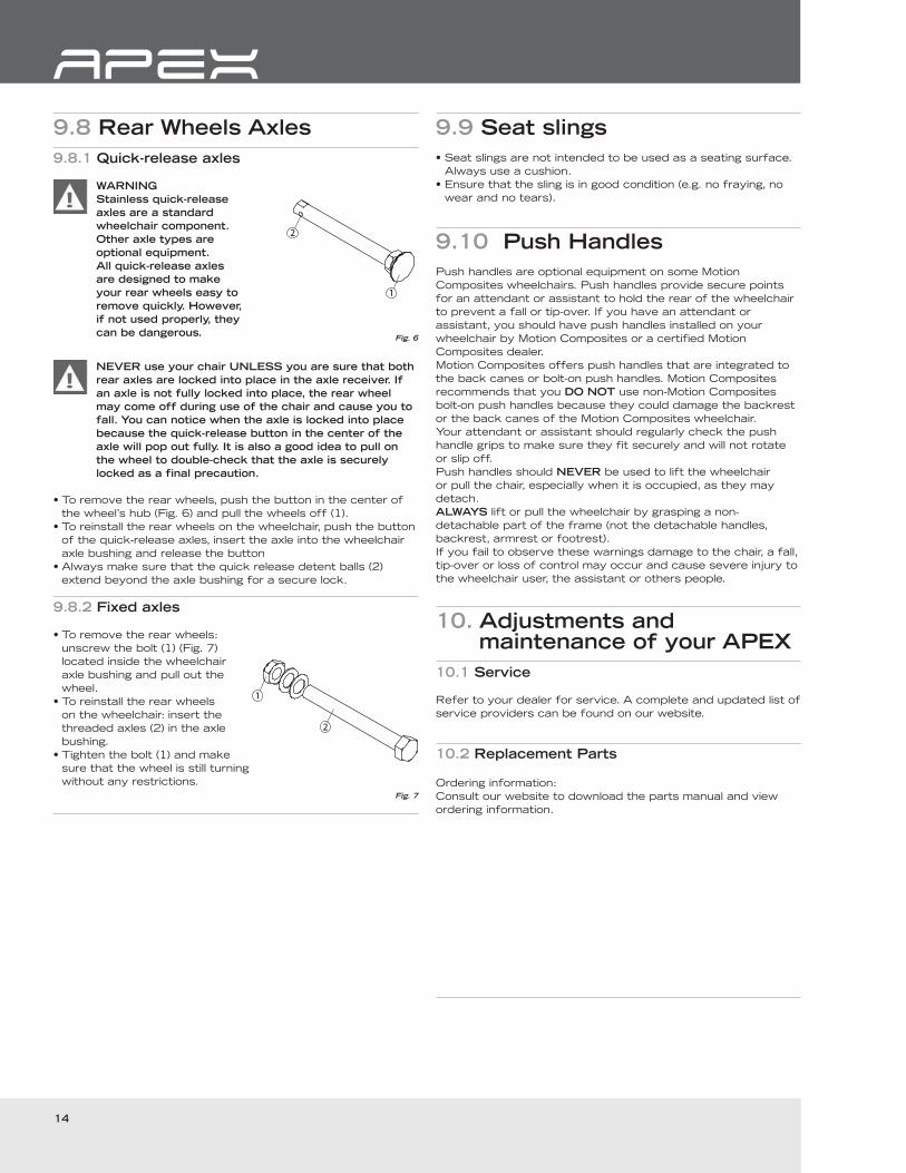
9.5.3 Swing-Away Armrests
1
To remove the armrests from the
wheelchair (Fig. 5):
• Lift them straight up to release the
armrest.
• To reinstall the armrests, insert
then back in the armrest receiver
(1) until they set into place.
Fig. 5
9.6 Seat belts
Use positioning belts ONLY to help support the rider’s
posture. Improper use of these belts may cause severe
injuries to the rider.
Make sure the rider does not slide down in the
wheelchair seat. If this occurs, the rider may suffer
chest compression or suffocate due to pressure from
the belts.
Never use belts as a motor vehicle restraint.
• The seatbelt should be used at all times in accordance with
instructions.
• There should be approximately one hand width of space
between the seat belt and thigh; do not exceed this amount
of space.
• Ensure that the seat belt is properly fastened as to avoid
serious injuries.
• In case of emergency, ensure that seat belt can be easily
unfastened.
9.6.1 Auto buckle and aircraft buckle seatbelts
• To fasten your seatbelt, insert the clip into the buckle until it
snaps.
• Make sure the belt is securely fastened.
• To unfasten your seat belt, lift the flap on the aircraft buckle
seatbelt or push the button on the auto buckle seatbelt.
• To adjust your seat belt, pull each strap towards the opposite
side until you get the desired tension and keep the buckle
centered.
9.6.2 Velcro Belt
• To fasten your seatbelt, insert the long side of the seatbelt
into the buckle on the other side.
• Apply pressure on the belt for a firm grip of the velcro.
9.7 Anti-Tippers
2
1
WARNING Motion
Composites strongly
recommends the use
of anti-tippers.
Anti-tippers (Fig. 5) were
designed to prevent falls from
the wheelchair.
• To remove or rotate the anti-
tippers up, push the release button (1) and pull out or rotate
the anti-tippers (2).
• To replace the anti-tippers, press the release button and insert
them into the frame until they snap into position.
• Highest Curb Clearance: 1 1/2” to 2”, depending on
configuration.
• Anti-tippers should not be used as a tipping-aid
• Always install both anti-tippers
Fig. 5
14
9.8 Rear Wheels Axles
9.8.1 Quick-release axles
WARNING
Stainless quick-release
axles are a standard
wheelchair component.
Other axle types are
optional equipment.
All quick-release axles
are designed to make
your rear wheels easy to
remove quickly. However,
if not used properly, they
can be dangerous.Fig. 6
NEVER use your chair UNLESS you are sure that both
rear axles are locked into place in the axle receiver. If
an axle is not fully locked into place, the rear wheel
may come off during use of the chair and cause you to
fall. You can notice when the axle is locked into place
because the quick-release button in the center of the
axle will pop out fully. It is also a good idea to pull on
the wheel to double-check that the axle is securely
locked as a final precaution.
• To remove the rear wheels, push the button in the center of
the wheel’s hub (Fig. 6) and pull the wheels off (1).
• To reinstall the rear wheels on the wheelchair, push the button
of the quick-release axles, insert the axle into the wheelchair
axle bushing and release the button
• Always make sure that the quick release detent balls (2)
extend beyond the axle bushing for a secure lock.
9.8.2 Fixed axles
• To remove the rear wheels:
unscrew the bolt (1) (Fig. 7)
located inside the wheelchair
axle bushing and pull out the
wheel.
• To reinstall the rear wheels
on the wheelchair: insert the
threaded axles (2) in the axle
bushing.
• Tighten the bolt (1) and make
sure that the wheel is still turning
without any restrictions.
Fig. 7
9.9 Seat slings
• Seat slings are not intended to be used as a seating surface.
Always use a cushion.
• Ensure that the sling is in good condition (e.g. no fraying, no
wear and no tears).
9.10 Push Handles
Push handles are optional equipment on some Motion
Composites wheelchairs. Push handles provide secure points
for an attendant or assistant to hold the rear of the wheelchair
to prevent a fall or tip-over. If you have an attendant or
assistant, you should have push handles installed on your
wheelchair by Motion Composites or a certified Motion
Composites dealer.
Motion Composites offers push handles that are integrated to
the back canes or bolt-on push handles. Motion Composites
recommends that you DO NOT use non-Motion Composites
bolt-on push handles because they could damage the backrest
or the back canes of the Motion Composites wheelchair.
Your attendant or assistant should regularly check the push
handle grips to make sure they fit securely and will not rotate
or slip off.
Push handles should NEVER be used to lift the wheelchair
or pull the chair, especially when it is occupied, as they may
detach.
ALWAYS lift or pull the wheelchair by grasping a non-
detachable part of the frame (not the detachable handles,
backrest, armrest or footrest).
If you fail to observe these warnings damage to the chair, a fall,
tip-over or loss of control may occur and cause severe injury to
the wheelchair user, the assistant or others people.
10. Adjustments and maintenance of your APEX
10.1 Service
Refer to your dealer for service. A complete and updated list of
service providers can be found on our website.
10.2 Replacement Parts
Ordering information:
Consult our website to download the parts manual and view
ordering information.
15
UserManual
10.3 Tools needed
The APEX was designed to be serviced with regular
tools. All screws and bolts are standard and can be
adjusted with a wrench, socket wrench, or Allen key.
Do not use air or electric tool, tightening should be
done manually.
The list of tools is at the end of this manual.
Some adjustments on the APEX are not possible due to the
use of security screws. These adjustments can only be
performed by Motion Composites.
10.4 General maintenance
10.4.1 Tire pressure
• Check tire pressure with a tire gauge.
• Verify recommended tire pressure, which is indicated on the
tire.
• Inflate if pressure is below recommended amount as labelled
on the sidewall.
• Do not inflate tire over recommended pressure, as stated on
the tire.
• Over inflation could result in tire failure and injury.
• Under inflation could result in a flat tire.
Max pressure
Pneumatic 1 3/8’’ 65 psi
Pneumatic High pressure 11/4 and 1 3/8’’ 110 psi
Pneumatic High pressure 1’’ 145 psi
10.4.2 Cleaning your wheelchair
• Use a soft clean cloth with soap and water to clean your
wheelchair.
• Rinse and dry the wheelchair adequately.
• DO NOT use solvent cleaners.
• DO NOT use abrasive cleaners.
• DO NOT use a pressure cleaner.
Paint Finish and frame
• Clean the painted surfaces with mild soap at least once a
month.
• Protect the paint with a coat of non-abrasive auto wax every
three months.
Axles and Moving Parts
• Clean around axles and moving parts WEEKLY with a slightly
damp cloth.
• Wipe off dust or dirt on axles or moving parts.
Upholstery:
• Hand-wash only (machine washing may damage fabric).
• Hang to dry only. DO NOT machine dry as heat will damage
fabric.
10.4.3 Storing and shipping your wheelchair
When not in use, keep your chair in a clean, dry area. Failure to
do so may result in your chair rusting and/or corroding.
If your chair has been in storage for more than a few weeks
you should make sure it is working properly. You should
inspect and service, if necessary, all items in section13 Safety
Inspection Checklist.
If your chair has been in storage for more than two months, it
should be inspected by a qualified technician.
When shipping you wheelchair use a strong cardboard box to
protect the wheelchair from any impact. Inspect the wheelchair
once it’s received.
10.5 Backrest
10.5.1 Removing/Installing the Back Canes
• The backrest rigidizer and the
back canes should only be
adjusted or modified by Motion
Composite or authorized party.
Fig. 8
10.5.2 Adjusting the Back Angle
1
2• Loosen screw (1) (Fig. 9) and
remove screw (2) from the
levelling device.
• Adjust to desired angle by
sliding the mechanism.
• Reinstall screw (2) and tighten
both screws to fit snugly.
Fig. 9
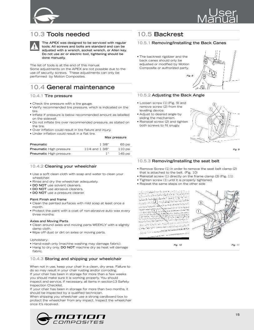
10.5.3 Removing/Installing the seat belt
• Remove Screw (1) in order to remove the seat belt clamp (2)
that is attached to the belt. (Fig. 10)
• Reinstall screw (1) directly on the frame clamp (3) (Fig. 11)
• Tighten screw (1) until it is properly tightened.
• Repeat the same steps on the other side
2
1 1
3
Fig. 10 Fig. 11
16
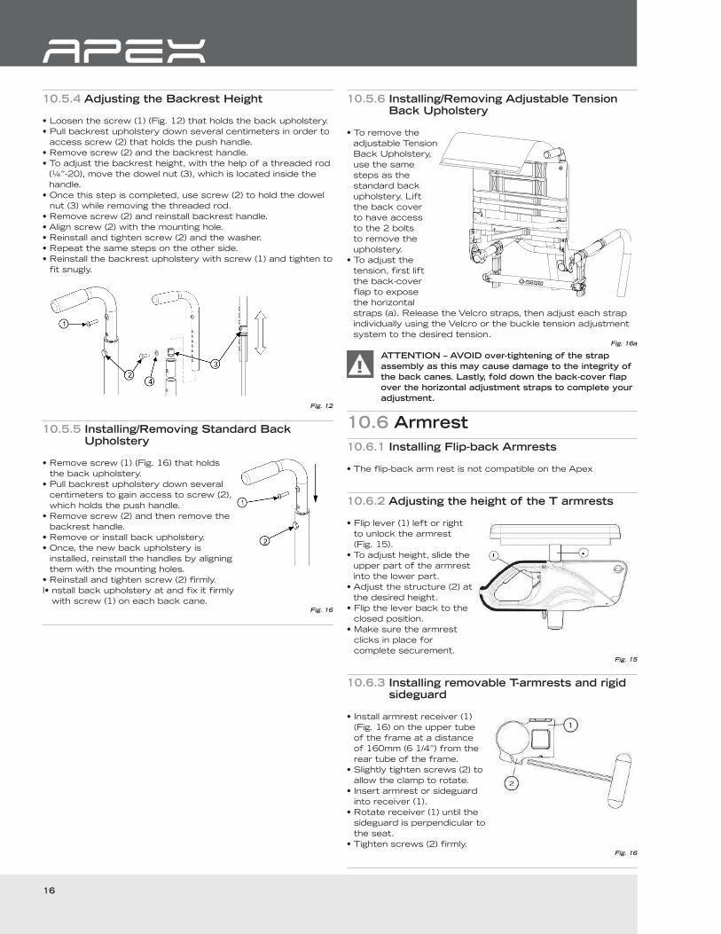
10.5.4 Adjusting the Backrest Height
• Loosen the screw (1) (Fig. 12) that holds the back upholstery.
• Pull backrest upholstery down several centimeters in order to
access screw (2) that holds the push handle.
• Remove screw (2) and the backrest handle.
• To adjust the backrest height, with the help of a threaded rod
(¼”-20), move the dowel nut (3), which is located inside the
handle.
• Once this step is completed, use screw (2) to hold the dowel
nut (3) while removing the threaded rod.
• Remove screw (2) and reinstall backrest handle.
• Align screw (2) with the mounting hole.
• Reinstall and tighten screw (2) and the washer.
• Repeat the same steps on the other side.
• Reinstall the backrest upholstery with screw (1) and tighten to
fit snugly.
Fig. 12
10.5.5 Installing/Removing Standard Back Upholstery
• Remove screw (1) (Fig. 16) that holds
the back upholstery.
• Pull backrest upholstery down several
centimeters to gain access to screw (2),
which holds the push handle.
• Remove screw (2) and then remove the
backrest handle.
• Remove or install back upholstery.
• Once, the new back upholstery is
installed, reinstall the handles by aligning
them with the mounting holes.
• Reinstall and tighten screw (2) firmly.
I• nstall back upholstery at and fix it firmly
with screw (1) on each back cane.Fig. 16
10.5.6 Installing/Removing Adjustable Tension Back Upholstery
• To remove the
adjustable Tension
Back Upholstery,
use the same
steps as the
standard back
upholstery. Lift
the back cover
to have access
to the 2 bolts
to remove the
upholstery.
• To adjust the
tension, first lift
the back-cover
flap to expose
the horizontal
straps (a). Release the Velcro straps, then adjust each strap
individually using the Velcro or the buckle tension adjustment
system to the desired tension.Fig. 16a
ATTENTION – AVOID over-tightening of the strap
assembly as this may cause damage to the integrity of
the back canes. Lastly, fold down the back-cover flap
over the horizontal adjustment straps to complete your
adjustment.
10.6 Armrest
10.6.1 Installing Flip-back Armrests
• The flip-back arm rest is not compatible on the Apex
10.6.2 Adjusting the height of the T armrests
• Flip lever (1) left or right
to unlock the armrest
(Fig. 15).
• To adjust height, slide the
upper part of the armrest
into the lower part.
• Adjust the structure (2) at
the desired height.
• Flip the lever back to the
closed position.
• Make sure the armrest
clicks in place for
complete securement.Fig. 15
10.6.3 Installing removable T-armrests and rigid sideguard
• Install armrest receiver (1)
(Fig. 16) on the upper tube
of the frame at a distance
of 160mm (6 1/4”) from the
rear tube of the frame.
• Slightly tighten screws (2) to
allow the clamp to rotate.
• Insert armrest or sideguard
into receiver (1).
• Rotate receiver (1) until the
sideguard is perpendicular to
the seat.
• Tighten screws (2) firmly.Fig. 16
17
UserManual
10.6.4 Replacing Armrest Pad
• Remove screws (1) (Fig.
17) located under pad
(through the tube).
• Replace with new
armrest pad.
• Reinstall screws (1) and
tighten firmly.
Fig. 17
10.6.5 Installing the Swing-away Armrest receiver
• Remove the two bolts (fig 18)
• Align the armrest receiver with the mounting holes of the
frame
• Install the new shoulder bolts in replacement of the existing
bolts and tighten firmly
1
Fig. 18
10.6.6 Adjusting Swing-away Armrest height
• Pull the armrest out of the receiver (1) (Fig. 19a).
• Remove screws (2) (Fig. 19b).
• Inside the armrest tube, slide the dowel nut with a long flat
screwdriver at the desired height (3)
• Reinstall screws (2).
• Reinsert armrest in receiver.
1
Fig. 19a Fig. 19b
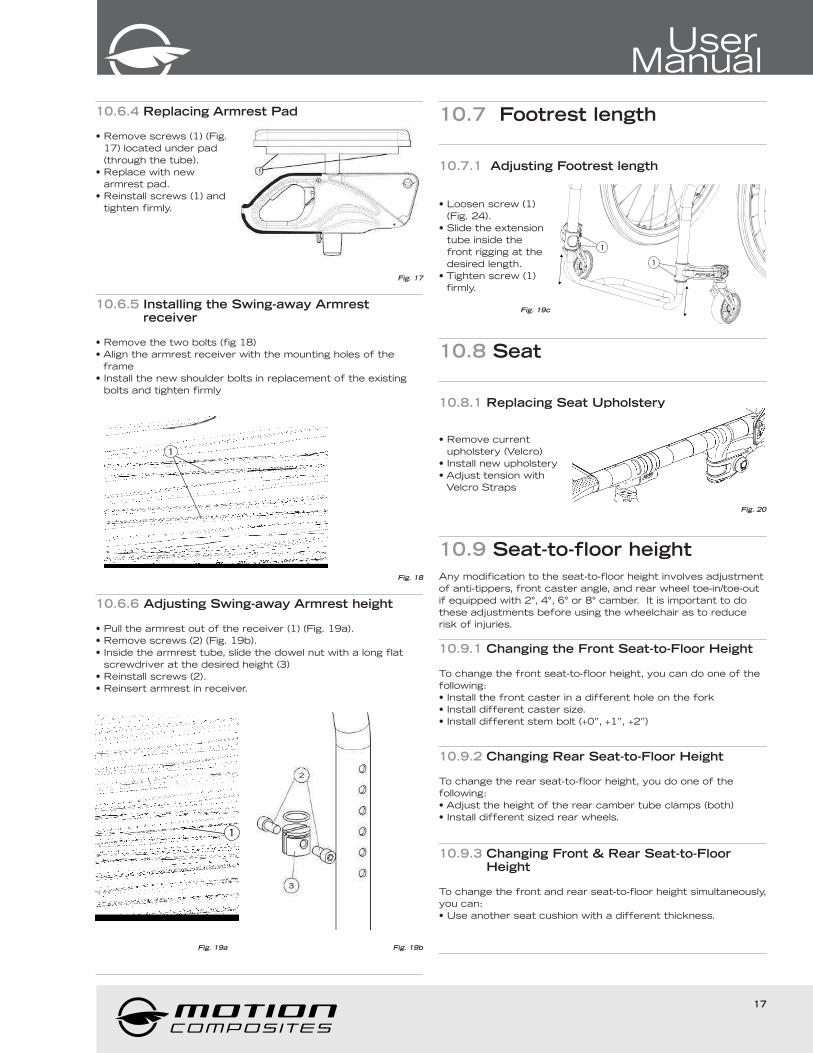
10.7 Footrest length
10.7.1 Adjusting Footrest length
1
1
• Loosen screw (1)
(Fig. 24).
• Slide the extension
tube inside the
front rigging at the
desired length.
• Tighten screw (1)
firmly.
Fig. 19c
10.8 Seat
10.8.1 Replacing Seat Upholstery
• Remove current
upholstery (Velcro)
• Install new upholstery
• Adjust tension with
Velcro Straps
Fig. 20
10.9 Seat-to-floor height
Any modification to the seat-to-floor height involves adjustment
of anti-tippers, front caster angle, and rear wheel toe-in/toe-out
if equipped with 2°, 4°, 6° or 8° camber. It is important to do
these adjustments before using the wheelchair as to reduce
risk of injuries.
10.9.1 Changing the Front Seat-to-Floor Height
To change the front seat-to-floor height, you can do one of the
following:
• Install the front caster in a different hole on the fork
• Install different caster size.
• Install different stem bolt (+0’’, +1’’, +2’’)
10.9.2 Changing Rear Seat-to-Floor Height
To change the rear seat-to-floor height, you do one of the
following:
• Adjust the height of the rear camber tube clamps (both)
• Install different sized rear wheels.
10.9.3 Changing Front & Rear Seat-to-Floor Height
To change the front and rear seat-to-floor height simultaneously,
you can:
• Use another seat cushion with a different thickness.
18
10.10 Front casters, forks and fork stem support assemblies
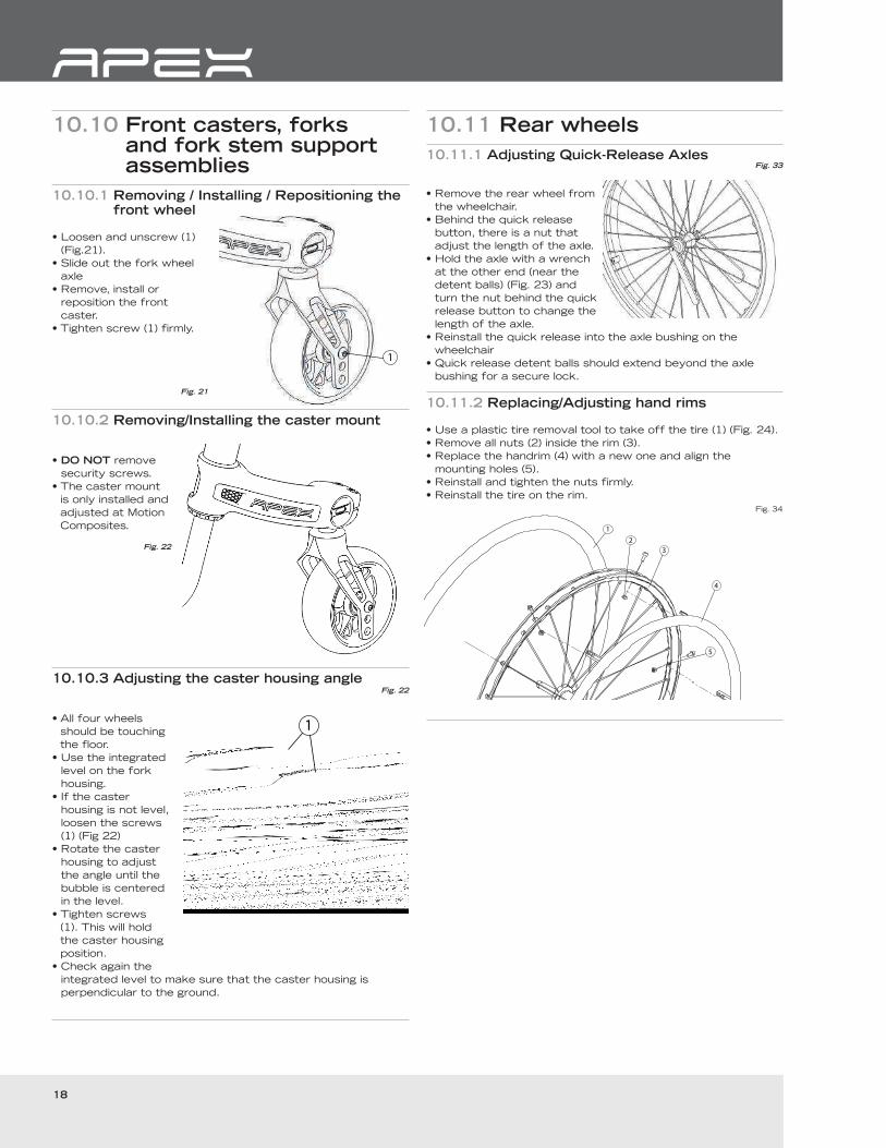
10.10.1 Removing / Installing / Repositioning the front wheel
1
• Loosen and unscrew (1)
(Fig.21).
• Slide out the fork wheel
axle
• Remove, install or
reposition the front
caster.
• Tighten screw (1) firmly.
Fig. 21
10.10.2 Removing/Installing the caster mount
• DO NOT remove
security screws.
• The caster mount
is only installed and
adjusted at Motion
Composites.
Fig. 22
10.10.3 Adjusting the caster housing angle Fig. 22
1• All four wheels
should be touching
the floor.
• Use the integrated
level on the fork
housing.
• If the caster
housing is not level,
loosen the screws
(1) (Fig 22)
• Rotate the caster
housing to adjust
the angle until the
bubble is centered
in the level.
• Tighten screws
(1). This will hold
the caster housing
position.
• Check again the
integrated level to make sure that the caster housing is
perpendicular to the ground.
10.11 Rear wheels
10.11.1 Adjusting Quick-Release AxlesFig. 33
• Remove the rear wheel from
the wheelchair.
• Behind the quick release
button, there is a nut that
adjust the length of the axle.
• Hold the axle with a wrench
at the other end (near the
detent balls) (Fig. 23) and
turn the nut behind the quick
release button to change the
length of the axle.
• Reinstall the quick release into the axle bushing on the
wheelchair
• Quick release detent balls should extend beyond the axle
bushing for a secure lock.
10.11.2 Replacing/Adjusting hand rims
• Use a plastic tire removal tool to take off the tire (1) (Fig. 24).
• Remove all nuts (2) inside the rim (3).
• Replace the handrim (4) with a new one and align the
mounting holes (5).
• Reinstall and tighten the nuts firmly.
• Reinstall the tire on the rim.
Fig. 34
19
UserManual
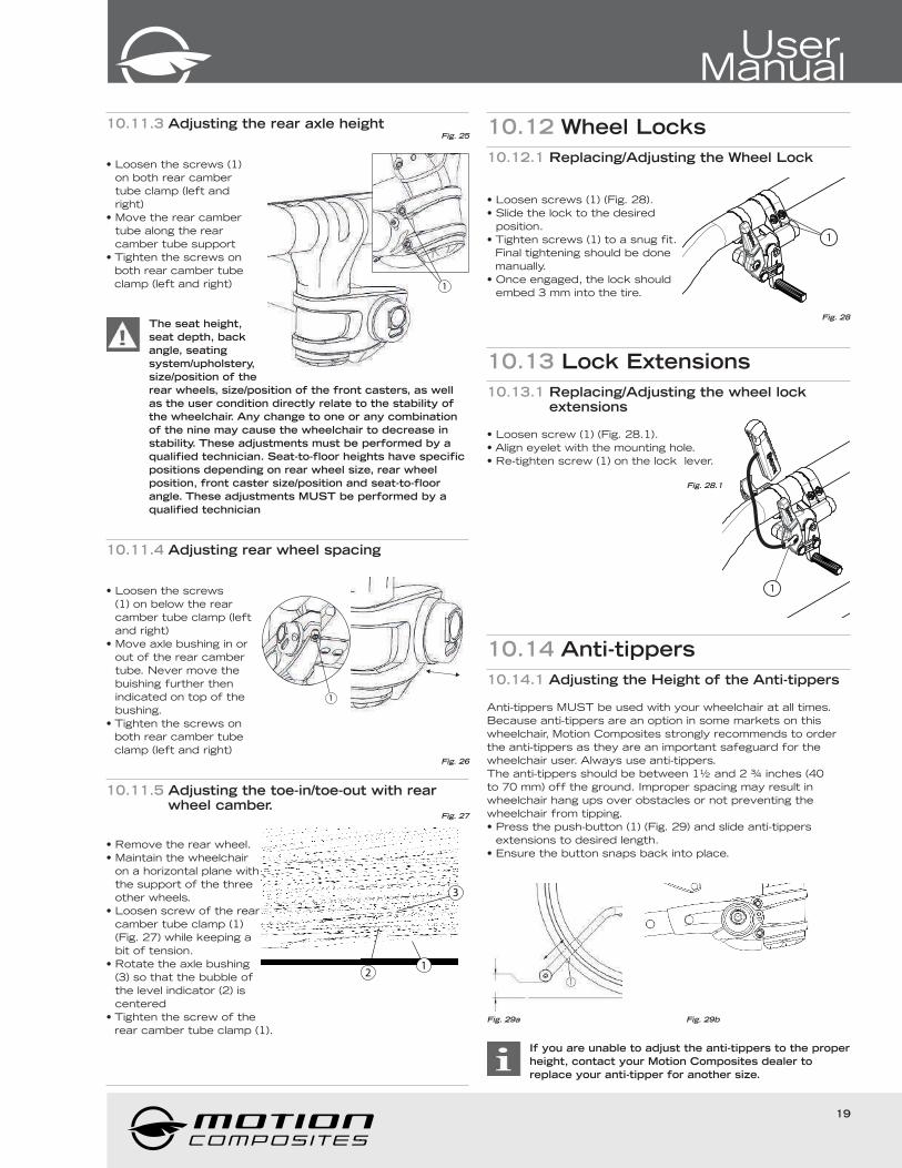
10.11.3 Adjusting the rear axle heightFig. 25
1
• Loosen the screws (1)
on both rear camber
tube clamp (left and
right)
• Move the rear camber
tube along the rear
camber tube support
• Tighten the screws on
both rear camber tube
clamp (left and right)
The seat height,
seat depth, back
angle, seating
system/upholstery,
size/position of the
rear wheels, size/position of the front casters, as well
as the user condition directly relate to the stability of
the wheelchair. Any change to one or any combination
of the nine may cause the wheelchair to decrease in
stability. These adjustments must be performed by a
qualified technician. Seat-to-floor heights have specific
positions depending on rear wheel size, rear wheel
position, front caster size/position and seat-to-floor
angle. These adjustments MUST be performed by a
qualified technician
10.11.4 Adjusting rear wheel spacing
1
• Loosen the screws
(1) on below the rear
camber tube clamp (left
and right)
• Move axle bushing in or
out of the rear camber
tube. Never move the
buishing further then
indicated on top of the
bushing.
• Tighten the screws on
both rear camber tube
clamp (left and right)Fig. 26
10.11.5 Adjusting the toe-in/toe-out with rear wheel camber.
Fig. 27
12
3
• Remove the rear wheel.
• Maintain the wheelchair
on a horizontal plane with
the support of the three
other wheels.
• Loosen screw of the rear
camber tube clamp (1)
(Fig. 27) while keeping a
bit of tension.
• Rotate the axle bushing
(3) so that the bubble of
the level indicator (2) is
centered
• Tighten the screw of the
rear camber tube clamp (1).
10.12 Wheel Locks
10.12.1 Replacing/Adjusting the Wheel Lock
1
• Loosen screws (1) (Fig. 28).
• Slide the lock to the desired
position.
• Tighten screws (1) to a snug fit.
Final tightening should be done
manually.
• Once engaged, the lock should
embed 3 mm into the tire.
Fig. 28
10.13 Lock Extensions
10.13.1 Replacing/Adjusting the wheel lock extensions
1
• Loosen screw (1) (Fig. 28.1).
• Align eyelet with the mounting hole.
• Re-tighten screw (1) on the lock lever.
Fig. 28.1
10.14 Anti-tippers
10.14.1 Adjusting the Height of the Anti-tippers
Anti-tippers MUST be used with your wheelchair at all times.
Because anti-tippers are an option in some markets on this
wheelchair, Motion Composites strongly recommends to order
the anti-tippers as they are an important safeguard for the
wheelchair user. Always use anti-tippers.
The anti-tippers should be between 1½ and 2 ¾ inches (40
to 70 mm) off the ground. Improper spacing may result in
wheelchair hang ups over obstacles or not preventing the
wheelchair from tipping.
• Press the push-button (1) (Fig. 29) and slide anti-tippers
extensions to desired length.
• Ensure the button snaps back into place.
Fig. 29a Fig. 29b
If you are unable to adjust the anti-tippers to the proper
height, contact your Motion Composites dealer to
replace your anti-tipper for another size.
20
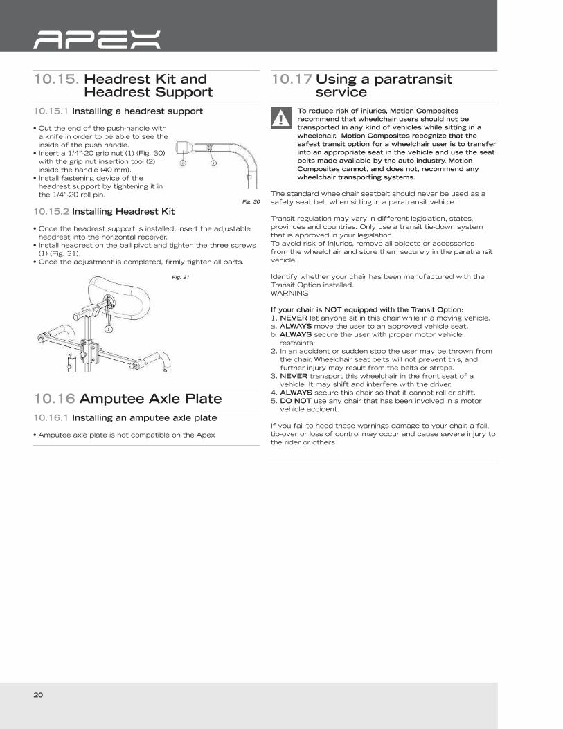
10.15. Headrest Kit and Headrest Support
10.15.1 Installing a headrest support
• Cut the end of the push-handle with
a knife in order to be able to see the
inside of the push handle.
• Insert a 1/4”-20 grip nut (1) (Fig. 30)
with the grip nut insertion tool (2)
inside the handle (40 mm).
• Install fastening device of the
headrest support by tightening it in
the 1/4”-20 roll pin.Fig. 30
10.15.2 Installing Headrest Kit
• Once the headrest support is installed, insert the adjustable
headrest into the horizontal receiver.
• Install headrest on the ball pivot and tighten the three screws
(1) (Fig. 31).
• Once the adjustment is completed, firmly tighten all parts.
Fig. 31
10.16 Amputee Axle Plate
10.16.1 Installing an amputee axle plate
• Amputee axle plate is not compatible on the Apex
10.17 Using a paratransit service
To reduce risk of injuries, Motion Composites
recommend that wheelchair users should not be
transported in any kind of vehicles while sitting in a
wheelchair. Motion Composites recognize that the
safest transit option for a wheelchair user is to transfer
into an appropriate seat in the vehicle and use the seat
belts made available by the auto industry. Motion
Composites cannot, and does not, recommend any
wheelchair transporting systems.
The standard wheelchair seatbelt should never be used as a
safety seat belt when sitting in a paratransit vehicle.
Transit regulation may vary in different legislation, states,
provinces and countries. Only use a transit tie-down system
that is approved in your legislation.
To avoid risk of injuries, remove all objects or accessories
from the wheelchair and store them securely in the paratransit
vehicle.
Identify whether your chair has been manufactured with the
Transit Option installed.
WARNING
If your chair is NOT equipped with the Transit Option:
1. NEVER let anyone sit in this chair while in a moving vehicle.
a. ALWAYS move the user to an approved vehicle seat.
b. ALWAYS secure the user with proper motor vehicle
restraints.
2. In an accident or sudden stop the user may be thrown from
the chair. Wheelchair seat belts will not prevent this, and
further injury may result from the belts or straps.
3. NEVER transport this wheelchair in the front seat of a
vehicle. It may shift and interfere with the driver.
4. ALWAYS secure this chair so that it cannot roll or shift.
5. DO NOT use any chair that has been involved in a motor
vehicle accident.
If you fail to heed these warnings damage to your chair, a fall,
tip-over or loss of control may occur and cause severe injury to
the rider or others
21
UserManual
11. Motion Composites limited warranty
Refer to the Motion Composites warranty document.
Warranty Service
If your wheelchair requires warranty service, please contact
an authorized Motion Composites
authorized international distributor. In the event of a defect in
material or workmanship, the Dealer or Distributor must obtain
a return authorization (RA) number from Motion Composites.
Motion Composites issues RA numbers only to authorized
Motion Composites Dealers and Distributors.
Do not return products to our factory without our prior
consent.
CONSUMER NOTICE
1 The foregoing warranty is exclusive, and in lieu of all other
express warranties, whether written or oral, express or
implied. Motion Composites shall not be liable for any
consequential or incidental damages whatsoever. By
registering your Motion Composites wheelchair, you will be
deemed to agree with all provisions of this warranty.
2 It is forbidden to alter or extend the foregoing express
warranty or to waive any of the limitations or exclusions.
12. Particular damages
12.1 Damages requiring service by a qualified service agent
If any of the following conditions are observed, the wheelchair
must be serviced by a qualified service agent:
• Any wheel adjustment;
• Any defective ball bearings of the forks;
• Any defective ball bearings of the front wheels;
12.2 Special damages that require the return of the wheelchair to the manufacturer
If any of the following conditions are observed, always contact
your service agent prior to sending your wheelchair for repairs
at Motion Composites.
• Part of the frame is cracked or broken.
• The thread of an adjustment nut is damaged.
• Problems continue to be identified after several adjustments
or repairs have been made by a qualified service agent.
12.3 Repair procedure
Parts that could be repaired by the owner:
Rear tire and inner tube.
• Parts serviced by the manufacturer or service center:
All parts of the wheelchair except for the tires and the inner-
tubes
• Parts that can be removed and sent to the manufacturer/
distributor or other party for repair:
Wheels, arm rest, foot rest, upholstery, cushion
• Circumstances in which the wheelchair should be sent for
service:
Broken bearings, loose spokes, wheel not aligned, loose bolt,
abnormal vibrations, noise or any deviation in the frame,
front stem is not perpendicular to floor, broken part like anti-
tippers, back canes, rips or tear on the upholstery and for
the yearly inspection
• Please contact our customer service agent for the complete
list of distributors or service centers.
• Some dealers may offer replacement units during the
service period. Please contact you service agent for full
details. Motion Composites will hold replacement parts for a
minimum of 10 years or propose a compatible spare option.
• If the wheelchair needs to be sent to a service center or to
the manufacturer for service, it should be packed carefully
in a cardboard box fitting the size of the wheelchair. The
anti-tippers, the foot rest and cushion should be removed
and packed in a small box inside the larger cardboard
box containing the wheelchair. The wheelchair should be
protected with a protective film to prevent from scratches
or wear.
22
Tools
Allen key: Keys:
2,5 mm 10 mm
3 mm 11 mm
4 mm 1/2’’ (13 mm)
5 mm
For Quick Release: Other:
7/16’’ (11 mm) Wrench
3/4’’ (19 mm) Phillips screwdriver
1’’ 1/16 (27 mm)
13. Safety Inspection ChecklistAt every use
Make sure wheelchair rolls easily and straight.
Check for vibrations, noise or any deviation from normal functioning.
Ensure wheel locks are working properly.
Ensure that front stem is perpendicular to floor.
Ensure wheel quick release are engaged and locked properly.
Visually inspect tires (front & rear) for debris, low pressure, flat spots or wear.
Make sure anti-tipper tubes are locked in place (if equipped).
Visually inspect fabric for protruding metal, rips or tears.
Ensure that hand grips are not loose (if equipped).
Check hand rims for rough edges and make sure they are free from grease or other contaminants.
Checks for component interference.
Check for irregular noise and rattles.
Weekly
Check tire pressure with a tire gauge
Check seat upholstery tension - It should be straight when the wheelchair is open and set in position.
Monthly
Check wheel alignment.
Check for free running of fork bearings.
Yearly
Have a complete inspection performed by a qualified technician.
Tire pressure could be adjusted by the owner or an
assistant with the proper tools. If any part appears not
to work properly after inspection, the wheelchair should
be immediately sent for repair to a qualified technician.
13.1 Disposal and Recycling the wheelchair
In the case of disposal, return the device to your dealer or
rehabilitation center.
All components of the product should be disposed and
recycled of in accordance with national environmental laws and
standards.
14. DECLARATION OF CONFORMITY
Name and Address of Product OwnerMotion Composites Inc.
We hereby declare that the below mentioned devices
have been classified according to the classification
rules and conform to the Essential Principles of Safety
and Performance as laid out in the Health Products
(Medical Devices) Regulations 93/42/CEE.
Medical Device(s):
APEX manual wheelchair
Manufacturing site:
Motion Composites Inc.
Risk classification:
Class 1 Medical Device (per 93/42/CEE).
Standards applied:• NF EN ISO 7176-1: Wheelchairs, part 1: Determination of static ability.• NF EN ISO 7176-5: Wheelchairs, part 5: Determination of dimensions,
mass and maneuvring space.• NF EN ISO 7176-8: Wheelchairs, part 8: Requirements and test methods
for static, impact and fatigue strengths.• NF EN ISO 7176-11: Wheelchairs, part 11: Test Dummies.• NF EN ISO 7176-15: Wheelchairs, part 15: Requirements for information
disclosure, documentation and labeling.
This declaration of conformity is valid from 2013/10/28.
I. Appendix
I.I TABLE “FRONT SEAT-TO-FLOOR HEIGHTS”
Front Frame Angle Height available ± ¼” (0.6 cm)
70° 14” (35.6 cm) to 21” (53.34 cm)
75° 14” (35.6 cm) to 21” (53.34 cm)
23
UserManual
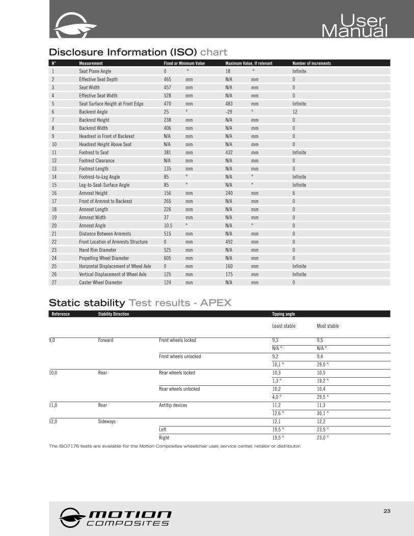
Disclosure Information (ISO) chartN° Measurement Fixed or Minimum Value Maximum Value, If relevant Number of increments
1 Seat Plane Angle 0 ° 18 ° Infinite
2 Effective Seat Depth 465 mm N/A mm 0
3 Seat Width 457 mm N/A mm 0
4 Effective Seat Width 528 mm N/A mm 0
5 Seat Surface Height at Front Edge 470 mm 483 mm Infinite
6 Backrest Angle 25 ° -29 ° 12
7 Backrest Height 238 mm N/A mm 0
8 Backrest Width 406 mm N/A mm 0
9 Headrest in Front of Backrest N/A mm N/A mm 0
10 Headrest Height Above Seat N/A mm N/A mm 0
11 Footrest to Seat 381 mm 432 mm Infinite
12 Footrest Clearance N/A mm N/A mm 0
13 Footrest Length 135 mm N/A mm 0
14 Footrest-to-Leg Angle 85 ° N/A ° Infinite
15 Leg-to-Seat-Surface Angle 85 ° N/A ° Infinite
16 Armrest Height 156 mm 240 mm 6
17 Front of Armrest to Backrest 265 mm N/A mm 0
18 Armrest Length 226 mm N/A mm 0
19 Armrest Width 37 mm N/A mm 0
20 Armrest Angle 10.5 ° N/A ° 0
21 Distance Between Armrests 515 mm N/A mm 0
22 Front Location of Armrests Structure 0 mm 492 mm 0
23 Hand Rim Diameter 525 mm N/A mm 0
24 Propelling Wheel Diameter 605 mm N/A mm 0
25 Horizontal Displacement of Wheel Axle 0 mm 160 mm Infinite
26 Vertical Displacement of Wheel Axle 125 mm 175 mm Infinite
27 Caster Wheel Diameter 124 mm N/A mm 0
Static stability Test results - APEXReference Stability Direction Tipping angle
Least stable Most stable
9,0 Forward Front wheels locked 9,3 9,5
N/A ° N/A °
Front wheels unlocked 9,2 9,4
10,1 ° 29,0 °
10,0 Rear Rear wheels locked 10,3 10,5
1,3 ° 19,2 °
Rear wheels unlocked 10,2 10,4
4,0 ° 29,5 °
11,0 Rear Antitip devices 11,2 11,3
12,6 ° 30,1 °
12,0 Sideways 12,1 12,2
Left 19,5 ° 23,5 °
Right 19,5 ° 23,0 °
The ISO7176 tests are available for the Motion Composites wheelchair user, service center, retailor or distributor.
24
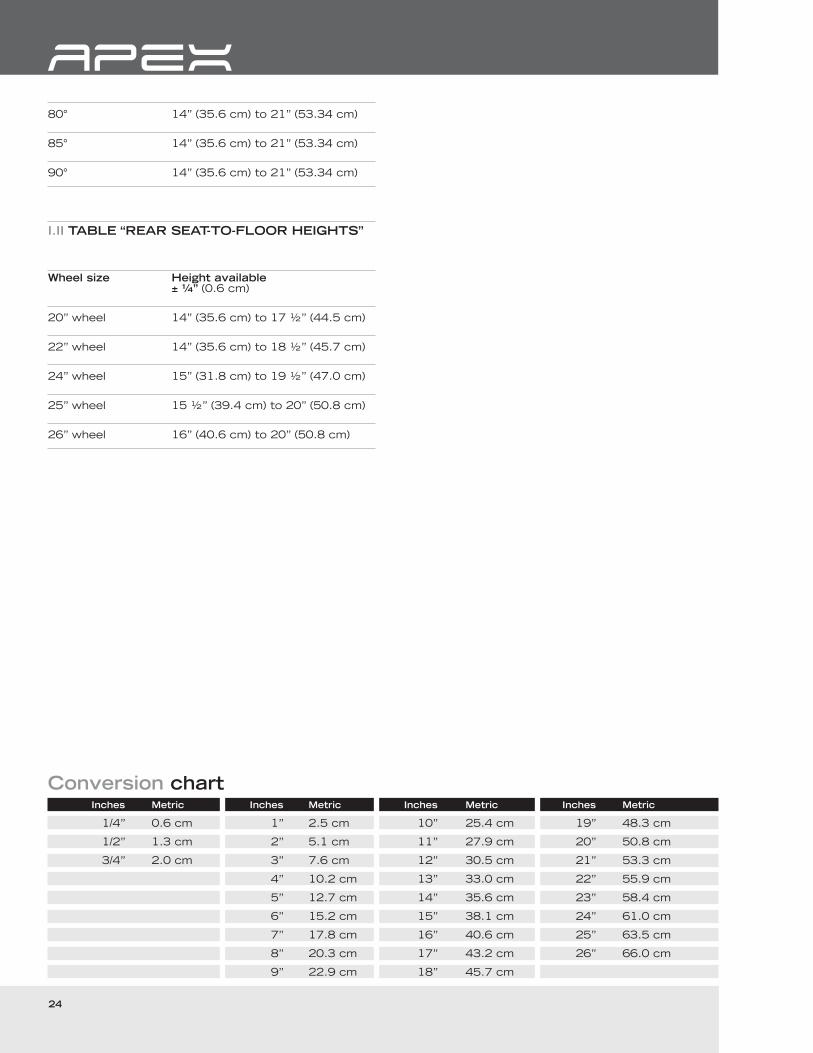
80° 14” (35.6 cm) to 21” (53.34 cm)
85° 14” (35.6 cm) to 21” (53.34 cm)
90° 14” (35.6 cm) to 21” (53.34 cm)
I.II TABLE “REAR SEAT-TO-FLOOR HEIGHTS”
Wheel size Height available ± ¼” (0.6 cm)
20” wheel 14” (35.6 cm) to 17 ½” (44.5 cm)
22” wheel 14” (35.6 cm) to 18 ½” (45.7 cm)
24” wheel 15” (31.8 cm) to 19 ½” (47.0 cm)
25” wheel 15 ½” (39.4 cm) to 20” (50.8 cm)
26” wheel 16” (40.6 cm) to 20” (50.8 cm)
Conversion chart Inches Metric Inches Metric Inches Metric Inches Metric
1/4” 0.6 cm 1” 2.5 cm 10” 25.4 cm 19” 48.3 cm
1/2” 1.3 cm 2” 5.1 cm 11” 27.9 cm 20” 50.8 cm
3/4” 2.0 cm 3” 7.6 cm 12” 30.5 cm 21” 53.3 cm
4” 10.2 cm 13” 33.0 cm 22” 55.9 cm
5” 12.7 cm 14” 35.6 cm 23” 58.4 cm
6” 15.2 cm 15” 38.1 cm 24” 61.0 cm
7” 17.8 cm 16” 40.6 cm 25” 63.5 cm
8” 20.3 cm 17” 43.2 cm 26” 66.0 cm
9” 22.9 cm 18” 45.7 cm