Embed Size (px)
Citation preview
SIRIUS CAPACITOR MODULE
User Manual
Model number: 3550-48-B-1.7C-TM-SD-A-X-X-G
Version 1.1; Release Date: January 2021
Author:
Mamoona Khalid

Introduction
The Sirius Capacitor Module (“Sirius”) is supercapacitor-based storage that uses supercapacitors as
storage cells instead of chemical cells. Kilowatt Labs’ proprietary balancing, control and charge
retention algorithms control the operation of the supercapacitor-based modules, making Sirius a safe,
efficient and effective alternative to chemical batteries wherever chemical batteries are deployed.
Legal Provisions
No part of this User Manual (“Manual”) may be reproduced, or transmitted, in any form or by any
means, without the prior written permission of Kilowatt Labs, Inc. (“Kilowatt” or the “Company”).
Specifications in this Manual are subject to change without notice. While every attempt has been
made to make the Manual accurate and up-to-date, users are cautioned that product improvements
may cause the Company to make changes to specifications without advance notice. Users are
encouraged to consult the Company or its Resellers before using the Manual. Neither the Company
nor its Resellers shall be liable for any indirect, incidental, or consequential damages under any
circumstances caused by reliance on the material presented, including, but not limited to, omissions,
typographical errors, arithmetical errors or listing errors in the content material. The content of this
manual shall not be modified without the written authorization of the Company.
Trademarks
All trademarks are recognized, even if not explicitly identified as such. Kilowatt Labs® is a registered
trademark of the Company.

Sirius Capacitor Module – User Manual Model Number - 3550-48-B-1.7C-TM-SD-A-X-X-G This manual is subject to change without notice and at the sole discretion of Kilowatt Labs, Inc.
Kilowatt Labs, Inc. | www.kilowattlabs.com
3
Contents
1 Safety Instructions: ................................................................................................................... 5
1.1 Symbols Convention: ........................................................................................................ 5
1.2 Safety Precautions: ........................................................................................................... 5
1.3 Modules Connection Safety Precautions: ......................................................................... 6
1.4 Shipping: ........................................................................................................................... 7
1.5 Qualified Installer:............................................................................................................. 7
2 Product Introduction: ............................................................................................................... 8
2.1 Product Part Number: ............................................................................................................. 8
2.2 Product Overview: .................................................................................................................. 8
2.2.1 Appearance: ....................................................................................................................... 8
2.2.2 Mechanical Drawings: ........................................................................................................ 9
2.2.3 Dimensions and Weight: .................................................................................................. 10
2.3 Product Description: ............................................................................................................. 11
3 Module Installation: ................................................................................................................ 15
3.1 Inspection: ............................................................................................................................ 15
3.2 Safety Gear: .......................................................................................................................... 15
3.3 Unpacking and Contents Check: ........................................................................................... 15
4 Electrical Installation: .............................................................................................................. 16
4.1 Cable Size: ............................................................................................................................. 16
4.2 Connecting Cable Lugs, Washers and Bolts to Module Terminals: ...................................... 16
4.3 Connecting Module to Power Supply: .................................................................................. 17
4.4 Connecting Module to Load: ................................................................................................ 18
4.5 Connecting Modules in Parallel: ........................................................................................... 19
4.6 Connecting Modules in Series: ............................................................................................. 20
4.6.1 Steps to Operate Modules in Series: ............................................................................... 20
5 Operation Procedures:............................................................................................................ 22
5.1 Module Configuration: .............................................................................................................. 22
5.2 Software Configuration:............................................................................................................ 23
6 Recovery Procedure: ............................................................................................................... 25
7 Automatic Safety Shutdown: .................................................................................................. 27
8 Trouble Shooting: ................................................................................................................... 29
9 Features: ................................................................................................................................. 30
9.1 Key Features: ...................................................................................................................... 30
Sirius Capacitor Module – User Manual Model Number - 3550-48-B-1.7C-TM-SD-A-X-X-G This manual is subject to change without notice and at the sole discretion of Kilowatt Labs, Inc.
Kilowatt Labs, Inc. | www.kilowattlabs.com
4
9.2 Physical features: ................................................................................................................ 30
9.3 Technical Features: ............................................................................................................. 31
10 Shelf Life:................................................................................................................................. 32
11 Maintenance: .......................................................................................................................... 32
12 Disposal: .................................................................................................................................. 32
13 Test Procedures: ..................................................................................................................... 33
13.1 Round Trip Efficiency Test: ................................................................................................. 33
13.2 Test Method for Self-Discharge: ..................................................................................... 34
14 FAQs: ....................................................................................................................................... 35

Sirius Capacitor Module – User Manual Model Number - 3550-48-B-1.7C-TM-SD-A-X-X-G This manual is subject to change without notice and at the sole discretion of Kilowatt Labs, Inc.
Kilowatt Labs, Inc. | www.kilowattlabs.com
5
1 Safety Instructions:
This manual contains instructions for unpacking, mounting, installation and operation of a Sirius
Module. Please read this manual carefully before operating the system and follow all warnings and
safety instructions to prevent accidents. The Sirius Module must be installed by trained personnel.
1.1 Symbols Convention:
Safety instructions and general information that appears in this manual are described.
1.2 Safety Precautions:
The Sirius Modules are designed to provide years of trouble-free operation. Proper handling is
required to avoid damage to the Module. In particular the following precautions should be observed.
• Personal Safety:
→ Always wear proper personal protective equipment (eyes protection, gloves and safety shoes).
→ Always make sure charger is set as recommended.
→ Always make sure chargers are disconnected while working on Modules.
Caution!
‘’Caution” indicates hazardous situation which, if not avoided could result in
minor or moderate injury.
Warning!
‘’Warning” indicates hazardous situation which, if not avoided could result
in major injury or death.
Danger!
‘’Danger” indicates hazardous situation which, if not avoided could result in
serious injury or death.
Note!
‘Note” provides tip that are valuable for optimal operation of your product.

Sirius Capacitor Module – User Manual Model Number - 3550-48-B-1.7C-TM-SD-A-X-X-G This manual is subject to change without notice and at the sole discretion of Kilowatt Labs, Inc.
Kilowatt Labs, Inc. | www.kilowattlabs.com
6
• Module Safety:
→ Do not subject the Module to strong impact.
→ Do not crush or puncture the Module.
→ Do not dispose the Module in a fire.
→ Do not charge the Module when the temperature is below -30oC.
→ Do not charge the Module when temperature is above 80oC.
→ Do not operate the Module above the specified voltage.
→ Under no circumstances charge/discharge the Module at more than 125A.
→ Under no circumstance must the charging voltage exceed 54 Vdc for more than 60 seconds.
→ Do not expose the Module to temperatures in excess of 80°C.
→ Do not place the Module near a heat source, such as a fireplace.
→ Do not disassemble the Module under any circumstances.
→ Do not touch the Module with wet hands.
→ Do not expose the Module to moisture or liquids.
→ Keep the Module away from children and animals.
→ Ensure precautions to prevent short-circuit under all circumstances.
→ Do not connect or disconnect terminals from the Module without first disconnecting the load.
→ Do not touch the terminals with conductors while the Module is charged. Serious burns, shock, or
material fusing may occur.
→ Protect surrounding electrical components from incidental contact.
→ When connecting to external devices ensure that galvanic isolation does not exceed 1000V.
→ Do not use the Module in open-environment, in rain or in a place exposed to water and other
liquids.
→ Do not subject the Module to high pressure.
→ It is not recommended to stack more than 2 Modules.
→ Do not step on the Module.
→ Do not drop the Module. Internal damage may occur that will not be visible.
→ Do not stack Modules once they have been removed from the packaging, instead the Modules
should be placed on shelving.
→ In case the Module is physically damaged due to any event, do not install and energize the Module
under any circumstances and immediately contact your Reseller.
1.3 Modules Connection Safety Precautions:
→ All Modules must be at 100% SOC before connecting in series or in parallel.

Sirius Capacitor Module – User Manual Model Number - 3550-48-B-1.7C-TM-SD-A-X-X-G This manual is subject to change without notice and at the sole discretion of Kilowatt Labs, Inc.
Kilowatt Labs, Inc. | www.kilowattlabs.com
7
→ The maximum number of Modules that can be connected in series is 8 with Module Combiner.
→ Modules cannot be connected in series-parallel combination under any circumstance.
1.4 Shipping:
Sirius Capacitor Modules are shipped out via Air and Sea.
• If the Modules are shipped via Air, please follow the instructions given below:
• Carefully remove the nails from all the four sides of the wooden box and open it.
• Remove the foam and cling wrap and open the carton box and lift the Module manually.
• If the Modules are shipped via Sea, please follow the instructions below:
• Carefully remove the Module from the pallets after cutting the packing strip holding the
Modules to the shipping pallets.
• Open the carton box and lift the Module manually.
1.5 Qualified Installer:
Selling and installation of this Module is only through the Company’s Resellers who are trained on
installation, operation and maintenance of the Sirius Modules.
Note!
If you want to connect more than 8 Modules in series, please contact your
Reseller.

Sirius Capacitor Module – User Manual Model Number - 3550-48-B-1.7C-TM-SD-A-X-X-G This manual is subject to change without notice and at the sole discretion of Kilowatt Labs, Inc.
Kilowatt Labs, Inc. | www.kilowattlabs.com
8
2 Product Introduction:
2.1 Product Part Number:
1) Capacity of Module in Wh
2) Nominal Voltage of the Module
3) Terminals are on the Front Side
4) Maximum Charge Rate of the Module
5) Total Monitoring
6) With Safety
7) With Alarm
8) General Module
2.2 Product Overview:
2.2.1 Appearance:
The appearance of the Sirius Module is shown below:

Sirius Capacitor Module – User Manual Model Number - 3550-48-B-1.7C-TM-SD-A-X-X-G This manual is subject to change without notice and at the sole discretion of Kilowatt Labs, Inc.
Kilowatt Labs, Inc. | www.kilowattlabs.com
9
2.2.2 Mechanical Drawings:
Front View
Side View

Sirius Capacitor Module – User Manual Model Number - 3550-48-B-1.7C-TM-SD-A-X-X-G This manual is subject to change without notice and at the sole discretion of Kilowatt Labs, Inc.
Kilowatt Labs, Inc. | www.kilowattlabs.com
10
2.2.3 Dimensions and Weight:
Width 600 mm
Depth 534 mm
Height 200 mm
weight 69 kg
Top View
Isometric View

Sirius Capacitor Module – User Manual Model Number - 3550-48-B-1.7C-TM-SD-A-X-X-G This manual is subject to change without notice and at the sole discretion of Kilowatt Labs, Inc.
Kilowatt Labs, Inc. | www.kilowattlabs.com
11
2.3 Product Description:
Object Mark Description
1 Circuit Breaker C125A Circuit breaker for switch ON/OFF Module.
2 Bypass Circuit Breaker C100A Circuit breaker for bypassing electronic switch.
3 Fault Reset Fault Reset Button
4 Aux Auxiliary USB
5 Comm Connector Communication Connector USB
6 Comm Status Communication Status LED
7 Terminal Status Terminal Status LED
8 LCD (16×2) LCD
9 F08 terminals Terminals
1. Circuit Breaker:
Circuit breaker is used to power ON the Module. It also acts as a second line of protection, if the circuit
fails to protect the Module from over current, the circuit breaker will trip.

Sirius Capacitor Module – User Manual Model Number - 3550-48-B-1.7C-TM-SD-A-X-X-G This manual is subject to change without notice and at the sole discretion of Kilowatt Labs, Inc.
Kilowatt Labs, Inc. | www.kilowattlabs.com
12
2. Bypass Circuit Breaker:
The bypass breaker is used to bypass electronic switch. It is used for series connection and recovery
of the Module.
3. Fault Reset:
Fault Reset is a push button which is used to turn ON the protected terminal manually after it turns
OFF due to any error.
The additional features of fault reset are as follows:
a) Hold fault reset for 5 seconds to toggle the protected terminal.
b) Hold fault reset for 3 seconds to reset fault if there is/are any.
c) Press fault reset button to check the state of charge and instantaneous power.
d) We can set the Current reading to zero.
Steps: To make the current zero, follow the steps below:
→ When current is not zero, the LCD will display the following message.
→ To make the current zero, hold the fault reset button for 3 seconds and the LCD will display the
following message.
This means that the current is now zero.
To return back to the normal screen, press the fault reset button once more or leave the Module idle
for 5 seconds.
Note!
Make sure that there are no external loads or charger before setting the
current to zero.

Sirius Capacitor Module – User Manual Model Number - 3550-48-B-1.7C-TM-SD-A-X-X-G This manual is subject to change without notice and at the sole discretion of Kilowatt Labs, Inc.
Kilowatt Labs, Inc. | www.kilowattlabs.com
13
4. Auxiliary USB:
This is an auxiliary connector with isolated UART or serial communication for wireless monitoring,
Module Combiner and future functions.
5. COMM Connector USB:
This is a COMM connector to monitor the Module using the Sirius software. FTDi chip is used for this
USB.
6. COMM Status LED:
COMM Status LED indicates the communication status.
• LED Status Indication:
Color Status Indication
Red Blinking Control Module is communicating with SIRIUS VIEW
Software.
Red Steady Control Module is not communicating with SIRIUS VIEW
Software.
Red Dimming Module is in power down state.
7. Terminal Status LED:
Terminal status LED indicates the F08 terminal status.
Color Status Indication
Green ON The F08 terminal is active
Green OFF The F08 terminal is not active.
8. LCD Description:
→ Once the power is switched ON from the circuit breaker, the Module gets power and the LCD
shows the following message after 3 seconds under normal operation:

Sirius Capacitor Module – User Manual Model Number - 3550-48-B-1.7C-TM-SD-A-X-X-G This manual is subject to change without notice and at the sole discretion of Kilowatt Labs, Inc.
Kilowatt Labs, Inc. | www.kilowattlabs.com
14
→ After 1 second, the following two LCD screens get switched with each other.
9. F08 Terminals:
These are the terminals of the Module having electronic switch protection that is limited to 100VDC
only. F08 terminals are used to connect the load or charger to the Module. There are also positive and
negative cables in the jumper cable set. The red one is positive (+), the black one is negative (-).
Note!
Never connect the red cable to the negative terminal of the Module.

Sirius Capacitor Module – User Manual Model Number - 3550-48-B-1.7C-TM-SD-A-X-X-G This manual is subject to change without notice and at the sole discretion of Kilowatt Labs, Inc.
Kilowatt Labs, Inc. | www.kilowattlabs.com
15
3 Module Installation:
3.1 Inspection:
Inspect the shipping carton for visible damage including cracks, dents, deformation and other visible
abnormalities prior to unpacking the Module. Document (photograph) any damage and report this to
your Reseller as well as to the shipping agent immediately. Remove the Module from the shipping
carton and retain the shipping materials until the unit has been inspected and is determined to be
operational.
3.2 Safety Gear:
Installation must strictly follow the national safety regulations in compliance with the enclosure,
installation, creepage, clearance, casualty, markings and segregation requirements of the end-use
application. Installation must be performed by professional installers only. Switch OFF the system and
check for hazardous voltages before altering any connection! Sirius Modules must be handled only by
qualified and trained personnel. Installation should not exert bending or twisting torque to the Module
enclosure.
3.3 Unpacking and Contents Check:
Check the contents of the package.
1. Sirius Capacitor Module: 3550Wh48VDC 3. Washers × 4
2. Bolts × 2 4. USB Cable A-B
Note!
Read the safety Instruction section before installation.
1 2 3
4

Sirius Capacitor Module – User Manual Model Number - 3550-48-B-1.7C-TM-SD-A-X-X-G This manual is subject to change without notice and at the sole discretion of Kilowatt Labs, Inc.
Kilowatt Labs, Inc. | www.kilowattlabs.com
16
4 Electrical Installation:
4.1 Cable Size:
We recommend a cable size of 35mm2 thick and 1m length to hold current up to 150A. Please use
thick cable size for lengths longer than 1m.
4.2 Connecting Cable Lugs, Washers and Bolts to Module Terminals:
Follow the sequence below to connect the washers, lugs and bolts to the positive and negative
terminals of the Sirius Module. Make sure connection is not loose.
Connecting washers, lugs and bolts to negative terminal of Module
Connecting washers, lugs and bolts to positive terminal of Module
Sirius Capacitor Module – User Manual Model Number - 3550-48-B-1.7C-TM-SD-A-X-X-G This manual is subject to change without notice and at the sole discretion of Kilowatt Labs, Inc.
Kilowatt Labs, Inc. | www.kilowattlabs.com
17
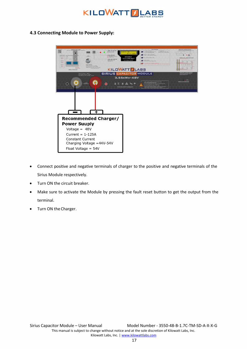
4.3 Connecting Module to Power Supply:
• Connect positive and negative terminals of charger to the positive and negative terminals of the
Sirius Module respectively.
• Turn ON the circuit breaker.
• Make sure to activate the Module by pressing the fault reset button to get the output from the
terminal.
• Turn ON the Charger.

Sirius Capacitor Module – User Manual Model Number - 3550-48-B-1.7C-TM-SD-A-X-X-G This manual is subject to change without notice and at the sole discretion of Kilowatt Labs, Inc.
Kilowatt Labs, Inc. | www.kilowattlabs.com
18
4.4 Connecting Module to Load:
• Connect positive and negative terminals of discharger to the positive and negative terminals of the
Sirius Module respectively.
• Turn ON the circuit breaker.
• Make sure to activate the Module by pressing the fault reset button to get the output from the
terminal.
• Turn ON the discharger.

Sirius Capacitor Module – User Manual Model Number - 3550-48-B-1.7C-TM-SD-A-X-X-G This manual is subject to change without notice and at the sole discretion of Kilowatt Labs, Inc.
Kilowatt Labs, Inc. | www.kilowattlabs.com
19
4.5 Connecting Modules in Parallel:
Any number of Modules can be connected in parallel.
• Steps to Connect Modules in Parallel:
Refer to the parallel combination of the Sirius Modules as shown below and make your
connection accordingly.
• Connect the positive (+) of the F08 Terminal of all Modules to the positive busbar.
• Connect the negative (-) of the F08 Terminal of all Modules to the negative busbar.
Note!
Switch ON only the circuit breaker when connecting in parallel.
Caution!
Charge all the Modules to 100% SOC or same voltage level before connecting
them in parallel.

Sirius Capacitor Module – User Manual Model Number - 3550-48-B-1.7C-TM-SD-A-X-X-G This manual is subject to change without notice and at the sole discretion of Kilowatt Labs, Inc.
Kilowatt Labs, Inc. | www.kilowattlabs.com
20
4.6 Connecting Modules in Series:
A maximum of 8 Modules can be connected in series with a Module Combiner.
• Steps to Connect Modules in Series:
Refer to the series combination of the Sirius Modules as shown below and make your connection
accordingly.
• Connect the positive (+) of the F08 terminal of the first Module with the F08 terminal of the next
Module.
• Take the Output Negative from first Module and Output Positive from the last Module.
4.6.1 Steps to Operate Modules in Series:
The figure given below shows n number of Modules connected in series.
1) Turning ON the Modules:

Sirius Capacitor Module – User Manual Model Number - 3550-48-B-1.7C-TM-SD-A-X-X-G This manual is subject to change without notice and at the sole discretion of Kilowatt Labs, Inc.
Kilowatt Labs, Inc. | www.kilowattlabs.com
21
1. First of all, turn ON the bypass breakers of all Modules.
2. Turn ON the circuit breakers of all Modules.
3. Turn ON the Main breaker.
2) Turning OFF the Modules:
1. Turn OFF the Main breaker.
2. Turn OFF the circuit breakers of all Modules.
3. Turn OFF the bypass breakers of all Modules.
Caution!
Charge all the Modules to 100% SOC or same voltage level before
connecting them in Series.
Note!
Switch ON the bypass circuit breaker when connecting in series, otherwise
it will damage the electronic switch.
Note!
Modules cannot be connected in series-parallel combination under any
circumstance.
Caution!
The bypass breaker is not protected with electronic switch, therefore
during over-voltage, under voltage and high temperature conditions, the
terminals will not shutdown. It only gives protection for over current
condition.
Warning:
Not following the steps in sequence may damage the Module.

Sirius Capacitor Module – User Manual Model Number - 3550-48-B-1.7C-TM-SD-A-X-X-G This manual is subject to change without notice and at the sole discretion of Kilowatt Labs, Inc.
Kilowatt Labs, Inc. | www.kilowattlabs.com
22
5 Operation Procedures:
5.1 Module Configuration:
Follow the steps below to switch ON the Module.
Step 1: Connecting the Load:
Connect the F08 terminals of the Module to the load.
Step 2: Module Start-Up:
1. Turn ON the circuit breaker by pushing the Blue lever upwards as shown in the picture below:
2. The picture below shows that the Module is turned ON.
3. Wait till the LCD screen on the Module displays initial values.

Sirius Capacitor Module – User Manual Model Number - 3550-48-B-1.7C-TM-SD-A-X-X-G This manual is subject to change without notice and at the sole discretion of Kilowatt Labs, Inc.
Kilowatt Labs, Inc. | www.kilowattlabs.com
23
4. Be sure you are able to see the terminal status LED OFF.
5. Press and hold the fault reset button, after 3 seconds the terminal status LED will change to Green.
6. Release the fault reset button.
Step 3: Module Shut-Down:
1. Press and hold the fault reset button to turn OFF the terminal. After 3 seconds the terminal status
LED will go OFF.
2. Make sure every indicator on the Module is OFF.
3. Turn OFF the Module by moving the Circuit breaker button to the OFF position.
5.2 Software Configuration:
To configure Sirius VIEW application, please follow the steps below.
1. Install the Sirius VIEW application on your system.
2. Connect the USB cable to the COMM connector USB slot to start communication and monitoring.
3. Turn ON the Sirius Module. (see Step.2: Module Start-up)
Note!
Use the bypass breaker button to connect the Modules in series and for
recovery purpose.
Note!
Always turn OFF the Module when not in use because it is self-powered. If
left ON, the self-discharge rate will increase.
Note!
Due to shipping laws and regulations, the Module may be shipped in partial
State of Charge.

Sirius Capacitor Module – User Manual Model Number - 3550-48-B-1.7C-TM-SD-A-X-X-G This manual is subject to change without notice and at the sole discretion of Kilowatt Labs, Inc.
Kilowatt Labs, Inc. | www.kilowattlabs.com
24
4. Double click on the Sirius VIEW application to execute it.
5. Please refer to Sirius VIEW manual version 5. Download Sirius VIEW manual from Amber and
Waseem Website. (https://www.amberandwaseem.com/downloads.html).

Sirius Capacitor Module – User Manual Model Number - 3550-48-B-1.7C-TM-SD-A-X-X-G This manual is subject to change without notice and at the sole discretion of Kilowatt Labs, Inc.
Kilowatt Labs, Inc. | www.kilowattlabs.com
25
6 Recovery Procedure:
When the Module voltage drops below a certain threshold, the control electronics turn OFF. To restart
the control electronics, follow the steps below.
1. Use the bypass breaker to turn the Module ON as shown below.
2. A power supply having voltage range of 44Vdc to 54Vdc and current range of 1A to 10A will be
required.
3. Connect the positive terminal of the power supply to the positive terminal of the F08 terminal and
negative terminal of the power supply to the negative terminal of the F08 terminal.
4. Remove the lock screw from the bypass circuit breaker with the help of screw driver.
5. Once the connection is done, turn ON the circuit breaker as shown below. The Module will
recharge and the control electronics will turn ON.
6. The event may take several minutes depending on the power supply used.
7. At this stage, remove the power supply and leave the Module for normal recharge.
Circuit Breaker Bypass Breaker

Sirius Capacitor Module – User Manual Model Number - 3550-48-B-1.7C-TM-SD-A-X-X-G This manual is subject to change without notice and at the sole discretion of Kilowatt Labs, Inc.
Kilowatt Labs, Inc. | www.kilowattlabs.com
26
• Recommended Charger for Recovery:
Maximum Current 10 A
Recommended Voltage 44V-54V
Caution!
Do not use more than 10A to recover the Module.

Sirius Capacitor Module – User Manual Model Number - 3550-48-B-1.7C-TM-SD-A-X-X-G This manual is subject to change without notice and at the sole discretion of Kilowatt Labs, Inc.
Kilowatt Labs, Inc. | www.kilowattlabs.com
27
7 Automatic Safety Shutdown:
The Module will automatically shut down under any excessive use conditions in order to prevent
damage to itself and to the connected equipment. Specified limits for excessive current, high voltage
and low voltage are provided in Module’s technical data sheet.
Cause of
Shutdown LCD Warning Message Description
Over-Current
(OCD)
When the Module has an Over-current fault,
the counter counts for 5 seconds and if the
current does not drop lower than the cut-off
and count down has reached to zero, the
buzzer alarms and the electronic switch will
shut-down.
Module Charge
Full
When the Module voltage reaches the
maximum voltage, the electronic switch will
shut down. This means that each cell from
the Module has reached to maximum rated
charge.
The event will be repeated if the charger is
still ON and operating in the same condition,
the buzzer alarms and LCD will show the
warning message.
Low Charge
Module
When the Module is in standby mode and it
reaches the minimum voltage, the LCD will
display this message every 30 seconds.
When the Module is connected to a load
and it reaches the minimum voltage, the
buzzer alarms, electronic switch will shut
down and LCD will display the message.
Over-
Temperature
When the Module has an Over-Temperature
fault, the buzzer alarms, the electronic
switch will shut down and LCD will display
the message.

Sirius Capacitor Module – User Manual Model Number - 3550-48-B-1.7C-TM-SD-A-X-X-G This manual is subject to change without notice and at the sole discretion of Kilowatt Labs, Inc.
Kilowatt Labs, Inc. | www.kilowattlabs.com
28
Terminal Over-
Temperature
When the Module has a terminal Over-
Temperature fault, the buzzer alarms, the
electronic switch will shut down and LCD will
display the message.
This means that electronic switch has
reached 80oC.

Sirius Capacitor Module – User Manual Model Number - 3550-48-B-1.7C-TM-SD-A-X-X-G This manual is subject to change without notice and at the sole discretion of Kilowatt Labs, Inc.
Kilowatt Labs, Inc. | www.kilowattlabs.com
29
8 Trouble Shooting:
Check the indicators on the front panel to determine the state of the Module. A warning state is
triggered when a condition, such as voltage, current or temperature, is beyond design limitations.
When the Module falls outside prescribed limits, it enters a warning state. When a warning is reported,
the Module immediately stops operation.
The possible warning messages are as follows:
Warning Messages Description Trouble Shooting
Over-Current (OC)
OC occurs when the current
goes above 125A or when
the Module is short-
circuited. In this event, the
electronic switch will shut
down.
Switch OFF the circuit breaker and
check the continuity across the
Module terminals to find whether
there is a short circuit. In case of a
short circuit, check the operating
circuitry and clear the short circuit.
Over-Temperature (OT)
OT occurs when the Module
temperature goes above
80°C. In this event, the
electronic switch will shut
down.
Shut down the Module and check
the surrounding temperature and
ensure the ambient temperature is
less than 80°C. If not leave the
Module to cool till the temperature
comes below 80°C. Now, turn ON
the circuit breaker.
Remove Module Charger/ Connect Module Charger
This happens when there is
some residual current. In
this event, the Module
gives alarm for full charge
or low charge and the
charger/discharger is also
disconnected but the
electronic switch is not
activated.
In Sirius VIEW application, select
Sirius Config then go to Calibrate
Zero Current. Press Calibrate. If you
see “No load current is set
successfully”, it means the current
is set to zero.
Sirius Capacitor Module – User Manual Model Number - 3550-48-B-1.7C-TM-SD-A-X-X-G This manual is subject to change without notice and at the sole discretion of Kilowatt Labs, Inc.
Kilowatt Labs, Inc. | www.kilowattlabs.com
30
9 Features:
9.1 Key Features:
• Low power consumption.
• Accurate SOC estimation.
• Cell balancing.
• Detection of circuit board errors.
• Long service life.
9.2 Physical features:
1. Electronic switch is used to control the terminals in Sirius Module. It has more life period than AC
or DC contactors and responds faster than any control methods.
2. Sirius Module has embedded functionality in the event of:
• High Cell Voltage
• Low Cell Voltage
• High Terminal Voltage
• Low Terminal Voltage
• High Terminal Current
• High Ambient Temperature
• High Module Temperature
3. Front panel of Sirius Module has LCD and Fault Reset Button. The fault reset button acts as a
multifunction button for monitoring and configuration. By using Reset fault Button and LCD user
can:
• Turn ON/OFF terminals of Module.
• Read Cell Voltages, Instantaneous Power, SOC, Terminal Voltage, Terminal Current, Terminal
Temperature and Ambient Temperature.
• Recalibrating Current Measurement by configuring zero current values.
• Activating Terminals to make Module more secure at first operation.
• Snooze alarms in case of repeating Module alarms.
4. LCD contrast can be configured anytime over Sirius VIEW Monitoring application.
5. Sirius Module can be used with Power Save Mode, this feature can be activated by Sirius VIEW
Monitoring application.
6. Front panel of Sirius Module also has 2 LEDs for letting user know the status of Module like

Sirius Capacitor Module – User Manual Model Number - 3550-48-B-1.7C-TM-SD-A-X-X-G This manual is subject to change without notice and at the sole discretion of Kilowatt Labs, Inc.
Kilowatt Labs, Inc. | www.kilowattlabs.com
31
• Communication LED (Red): Blinking while communicating.
• Terminal LED(Green): Active while terminal is ON, Inactive while terminal is OFF.
9.3 Technical Features:
1. Sirius Module has one processor for alarm monitoring, communication and datalogging features.
2. Sirius Module has internal memory card that is logging every 10 seconds value of:
• Terminal Voltage
• Terminal Current
• Module SOC
• Ambient Temperature
• Terminal Temperature
• Time Stamp
3. Internal logged data can be easily extracted over Sirius VIEW Monitoring application. Size of
internal memory is 8GB and Module can keep logging 30 days of data without any interruption.
4. User can delete and read SD card memory over Sirius VIEW Monitoring Application.
5. Sirius Module has one of the best ADC to increase measurement accuracy up to 6µV level.
6. Sirius Module has advanced algorithm to control Module in safest way. This algorithm can be
upgraded by user with updating firmware of Sirius Module over Sirius VIEW Monitoring.
7. Sirius Module firmware can be customized easily based on user needs.
8. Sirius Module has USB interface to communicate with Host PC for:
• Measurement Monitoring
• Alarm Monitoring
• System Configuration
• Measurement Calibration
• Manual/Auto Data Logging\Module firmware updating
• Internal SD card reading/refreshing
• Statistical Analyzing/ Graphical result

Sirius Capacitor Module – User Manual Model Number - 3550-48-B-1.7C-TM-SD-A-X-X-G This manual is subject to change without notice and at the sole discretion of Kilowatt Labs, Inc.
Kilowatt Labs, Inc. | www.kilowattlabs.com
32
10 Shelf Life:
Shelf life is the life of the Module in years from the date it is manufactured to the time it is first
operated. The shelf life of supercapacitor cell is 10 years.
11 Maintenance:
The Sirius Module does not require periodic maintenance.
12 Disposal:
Dispose according to local regulation.

Sirius Capacitor Module – User Manual Model Number - 3550-48-B-1.7C-TM-SD-A-X-X-G This manual is subject to change without notice and at the sole discretion of Kilowatt Labs, Inc.
Kilowatt Labs, Inc. | www.kilowattlabs.com
33
13 Test Procedures:
13.1 Round Trip Efficiency Test:
Round Trip efficiency test is performed to evaluate the performance of the Module. There are three
factors to be considered in the design of the test cycle for round trip efficiency.
• How to charge and discharge the Sirius Module.
• At what voltage to start and end the charge/discharge?
• At which points to do the measurement.
Considering the efficiency and cost involved in the production line, we used constant current load test
method for Round trip efficiency characterization.
Test Equipment:
• DC Charger test system or any other test system which can be used to charge and discharge
Module with test cycle programing.
Test Temperature:
• Room temperature 23oC ±2oC.
• Temperature controlled chamber can be used if testing at any environment other than room
temperature
Test Current:
• Different current within the maximum limit specified by the test equipment manufacturer can be
applied to the test.
• We took test currents in the range of 20-70A with current steps of 10.
Test Process:
Step 1: Rest (open circuit):
• Record test time, test current, and voltage at the start of the test (t1, I1, V1).
Step 2: Charge Cycle:
• Charge voltage to its maximum voltage.
• Record test time, test current, voltage and total charge energy at the end of charge cycle (t2, I2,
V2, E1).

Sirius Capacitor Module – User Manual Model Number - 3550-48-B-1.7C-TM-SD-A-X-X-G This manual is subject to change without notice and at the sole discretion of Kilowatt Labs, Inc.
Kilowatt Labs, Inc. | www.kilowattlabs.com
34
Step 3: Discharge Cycle:
• Discharge Module to its minimum voltage.
• Record test time, test current, voltage and total discharge energy at the end of discharge cycle (t3,
I3, V3, E2).
Step 4: Round Trip Efficiency Calculation:
Round trip efficiency = [total discharge energy (E2)
total charge energy (E1)] × 100
13.2 Test Method for Self-Discharge:
The self-discharge method is designed to see the natural decay of the Module’s total voltage over time
after it is fully charged. The result will be influenced by the temperature, the voltage at which the
device is charged and the aging condition.
The following steps describe the process for measuring self-discharge.
Step 1:
• Charge the battery to its maximum voltage.
• Record the voltage (Vmax).
Step2:
• Leave the battery idle for a period of 1 month.
• Record the open circuit voltage after 1 month (Voc).
Step 3:
• Self-discharge (%) = [Vmax−Voc
Voc] × 100

Sirius Capacitor Module – User Manual Model Number - 3550-48-B-1.7C-TM-SD-A-X-X-G This manual is subject to change without notice and at the sole discretion of Kilowatt Labs, Inc.
Kilowatt Labs, Inc. | www.kilowattlabs.com
35
14 FAQs:
Q. How to determine the current status (charging/discharging)?
A. When the current value on the LCD is negative it means the Module is discharging and when it is
positive, it means the Module is charging.
Q. The current reading on the LCD is not accurate for the first charging/discharging Session?
A. The user should wait for 5 minutes after starting the Module for the first charge/discharge session
(it is only one time for warming up).
Q. How to reset the current to zero?
A. Please refer to the video.
Q. If we leave the Module turned ON after it reaches 44V or below. What will happen?
A. When the Module reaches the minimum voltage and below (whether terminal is ON or OFF), the
LCD will display “Low Charge Module” message. (Please refer to Low charge module section in user
manual).
Q. What will happen if the Module is totally empty? or If the Module is left on after it is drained,
will it keep draining to the point that it will not charge without some sort of manual recovery?
A. Getting Module totally empty (zero voltage) after leaving the Module stand by for long time is
normal, so in this case LCD & electronic switch will be OFF, but the Module can be recovered. (Please
refer to recovery procedure in the user manual).
Q. Self-consumption of the Module when connected to a power source and the terminal is ON, seem
to consume about 1Amp or about 1kWh per day?
A. The maximum current of the Module BMS is 60mA not 1A.
Q. We are getting multimeter value different (Voltage, Current Charge/discharge, Temperature,
Energy) from that displayed in LCD across the terminal? or why has the Module lost the calibration?
A. It is normal since each electronic tool or equipment needs calibration after long time of use to get
accurate results, and for that the Module needs to be calibrated. But before that please check the
following:
• Firstly, double check the value with accurate meter (we suggest Fluke multimeter), if the deviation
between the Module and multimeter is less than ±0.5% it is acceptable.
• Secondly, if the deviation is more than ±0.5%, the Module needs calibration. Please consult with
your Reseller for calibration.

Sirius Capacitor Module – User Manual Model Number - 3550-48-B-1.7C-TM-SD-A-X-X-G This manual is subject to change without notice and at the sole discretion of Kilowatt Labs, Inc.
Kilowatt Labs, Inc. | www.kilowattlabs.com
36
Q. What could happen when connecting different model of Sirius Module parallel/series together?
A. Modules can be connected in parallel or in series if they will have:
- Same Voltage
- Same Capacity
It is possible but not recommended especially connecting old BMS design to the new one. The system
might get unpredictable during extreme scenarios like Module charge full or low.
Q. Is it possible to connect Sirius Module in parallel with other chemical batteries such as lithium-
ion or lead acid?
A. It is possible but not recommended. Make sure the total voltage of each battery is the same as the
Module and the charging voltage does not exceed the Module’s maximum voltage. The possible
drawback is that you will not get the total capacity of the chemical battery because extreme voltages
are not the same.
Q. If we set the cutoff voltage on the charge controller systems /inverter end to 45V, will that allow
the Module to sit at idle for longer periods of time to avoid an undervoltage situation.
A. Yes.
Q. Which is most compatible charge controller systems/ inverter, and whether any charge
controllers have been integrated with Sirius in this application?
A. All charge controllers that are compatible with our Module specification (please refer to user
manual of Module) can be used with Sirius Module, however you must follow the charging curve of
Sirius module.
Also, Kilowatt labs can provide Centauri Energy Server for microgrid system for more information
please visit www.kilowattlabs.com.
Figure 1:Sirius Module charging curve.

Sirius Capacitor Module – User Manual Model Number - 3550-48-B-1.7C-TM-SD-A-X-X-G This manual is subject to change without notice and at the sole discretion of Kilowatt Labs, Inc.
Kilowatt Labs, Inc. | www.kilowattlabs.com
37
Q. How to check charging/discharging energy of Module?
A. Please refer to “Overview of Sirius VIEW Application” section in Sirius VIEW application manual.
Q. How to reach the rated capacity of Module?
A. The display shows the total delivered energy (discharged) from the time the Module started till
current time, and the Module has ~70A at 1C and 125A at 1.7C(Max. charging current). So, to obtain
the standard energy 3.55kWh, start the charging cycle from minimum voltage 44V to maximum
voltage 54V with constant current of 70 A as shown in charging curve of Sirius module, then for
discharging cycle start from maximum voltage 54V to minimum voltage 44V with 70 A constant
current. (Please refer to Sirius VIEW application manual for Round trip efficiency).
Q. What would be the effect on energy when charge/discharge the Module at different C-ratings?
A. When the charge rate increases, the time for charging/discharging decreases, which means that
maximum energy can be obtained in a short period of time as shown in the table below.
Charge rate
(C)
Charging current
(Amp)
Discharging current
(Amp)
Time
(Minutes)
0.28 20 20 Approx. 4hrs
0.5 37 37 Approx. 2hrs
1 70 70 Approx. 1hr
1.35 100 100 45 mins
1.7 125 125 35 mins
Table 2: Charge rate with its corresponding time.
Q. Why the Module needs twice of power cycle?
A. When the Module is switched OFF and the Sirius VIEW is still open you have to wait for 10 Sec
(since the application is still communicating with the Module) before turning ON the Module, or either
by terminating the Sirius VIEW or by disconnecting the communication cable.
Q. How much is the capacity of the internal storage (SD Card)?
A. 8GB SD Card is used in the Module which logs 85 bytes of data per 10 seconds. Note that data
logging should be turned ON before the Module will start logging and data logging is limited to 30
days. After reading the data the Module will delete it automatically. By default, data logging is OFF for
firmware version 2. 0 and above.
Q. Do I need to use Sirius VIEW Software?
A. The Module can work stand-alone without the software however, the software can be used to
monitor and extract the data & measurement as well as to enhance the performance of the Module.

Sirius Capacitor Module – User Manual Model Number - 3550-48-B-1.7C-TM-SD-A-X-X-G This manual is subject to change without notice and at the sole discretion of Kilowatt Labs, Inc.
Kilowatt Labs, Inc. | www.kilowattlabs.com
38
Q. How do I know if there is firmware issue in the Module?
A. Please refer to Sirius VIEW monitoring software manual Configuration of Module and Software
section.
Q. What kind of issues can happen about firewall and antivirus programs?
A. There will be no problem as far as the software run as administrator.
Q. How to calibrate Module parameters?
A. To calibrate Module parameter like (Voltage, Current, Temperature, Energy). Kindly consult with
your Reseller for calibration procedure.
Q. What is the reason if the LED isn’t working at all?
A. Due to different reasons that may happen such as:
• If we can get the output (Terminal, software communication), the LED may have some technical
issues.
• The protected terminal is not working.
Please consult with your Reseller.
Q. How to troubleshoot the communication between the Module and PC?
A. If you face any communication difficulties between the Module and PC please troubleshoot as
follows:
• Double Check the cable connection (try to use anther USB cable).
• Try to use anther port in the PC.
• Check the Module USB drive in your PC from setting then search for Device Manager then go to
ports as shown below (Please refer to USB serial driver quick install).
After the troubleshooting if the problem still doesn’t solve, please consult with your Reseller.
Figure: Module Port &com number

Sirius Capacitor Module – User Manual Model Number - 3550-48-B-1.7C-TM-SD-A-X-X-G This manual is subject to change without notice and at the sole discretion of Kilowatt Labs, Inc.
Kilowatt Labs, Inc. | www.kilowattlabs.com
39
Q. The Module is showing Contact Service.
A. Contact your Reseller for customer support.
Q. How to update the Firmware.
A. New Firmware is uploaded to https://www.amberandwaseem.com/.Always check the website for
an update.
Q. The Module doesn’t seem to show correct State of Charge (SOC).
A. The Module is using the previous data to correct the state of charge in the long run. Charge the
Module to maximum Voltage and then discharge it to cut-off Voltage and repeat the process several
times to correct the SOC. Note that open voltage is not directly related to SOC.
Q. Can the Sirius Module be installed standing vertically with the connection facing up without
potentially stressing the cells inside the Module?
A. Yes, but NOT in a movable\vibrating position.
Q. What is the difference between the ‘’balancing “and “auto balancing” in “set Config” tab in Sirius
VIEW?
A. Balancing: Balancing can be activated from any voltage level when the Module is in standby mode
(Zero current). When all the cells get balance, the balancing will stop. The time required to balance all
cells depends on cells condition.
Auto balancing: Auto balancing is activated automatically during charging when the cells get
unbalanced.
Note that it is activated only when the Module Voltage reaches ~52 V.
Q. Can balancing and auto balancing options be activated at a same time?
A. Yes.
Q. When to use Sirius Config?
A. The Module is received with full settings and the most updated firmware, however, if you want to
calibrate parameters (current, voltage, date and time, alarm, temperature) you can use Sirius Config
for calibrating. For more information contact your Reseller.