Embed Size (px)
Citation preview
APPLICATION NOTE
User Manual of High-EndRDS/EON Car Radio System
CCR612 (V0.3)AN96029
Philips Semiconductors
User Manual of High-End RDS/EONCar Radio System CCR612 (V0.3)
Application Note96029
© Philips Electronics N.V. 1997
All rights are reserved. Reproduction in whole or in part is prohibited without the prior written consent of the copy-right owner.
The information presented in this document does not form part of any quotation or contract, is believed to beaccurate and reliable and may be changed without notice. No liability will be accepted by the publisher for anyconsequence of its use. Publication thereof does not convey nor imply any license under patent- or other industrialor intellectual property rights.
Purchase of Philips I2C components conveysa license under the I2C patent to use the com-ponents in the I2C system, provided thesystem conforms to the I2C specificationsdefined by Philips.
Abstract
The CCR612 is a computer controlled car radio system based on a P83CE528 micro controller. It controls ahigh-end AM/FM car radio with RD(B)S, EON and various I2C controlled peripherals. It can be interfaced to aSCC600 CD-changer
The system contains functions such as PLL tuning, IF control, stereo decoding, RDS/RBDS+EON decoding, IAC,sound switching, sound fader control, LCD display, cassette interface, external audio input jack and a detachablefront. An interface to control a CD-changer is also provided.
Radio control and RDS/RBDS+EON processing are combined in a single microcontroller.
"The purchase of Philips’ complete set of Integrated Circuits as specified in this User Manual for manufacture ofa radio system conforming the relevant specification as herein given, secures immunity from suit onunauthorized use of those Philips’ patent rights, which specifically relate to automatic broadcast station storage(AST) and/or radio data system (RDS) features."
2
Philips Semiconductors
User Manual of High-End RDS/EONCar Radio System CCR612 (V0.3)
Application Note96029
User Manual of High-End
APPLICATION NOTE
RDS/EON Car Radio SystemCCR612 (V0.3)
AN96029
Author(s):
A. DemmersM. Verheijden
Product Concept & Application Laboratory Eindhoven,The Netherlands
Keywords
Car RadioRDS
RBDSEON
CCR612ICE (TEA6811 / TEA6822)
SOFAC (TEA6320, 6321, 6322 or 6323)CD-changer
Number of pages: 94
Date: 1996-05-24
3
Philips Semiconductors
User Manual of High-End RDS/EONCar Radio System CCR612 (V0.3)
Application Note96029
Summary
CCR612 is a computer controlled car radio system based on a P83CE528 microcontroller. It controls a high-endAM/FM car radio with R(B)DS (Radio Broadcasting Data System), EON (Enhanced Other Network) and variousI2C-bus controlled peripherals.
The system contains functions such as PLL tuning, IF control, stereo decoding, RDS/RBDS+EON decoding, IAC,sound switching, sound fader control, LCD display, cassette interface, external audio input jack and a detachablefront. An interface to control a CD-changer is also provided.
Radio control and RDS/RBDS+EON processing are combined in a single microcontroller.
4
Philips Semiconductors
User Manual of High-End RDS/EONCar Radio System CCR612 (V0.3)
Application Note96029
CONTENTS
1 INTRODUCTION . . . . . . . . . . . . . . . . . . . . . . . . . . . . . . . . . . . . . . . . . . . . . . . . . . . . . . . . . . . . . . . 111.1 Definitions, Acronyms and Abbreviations . . . . . . . . . . . . . . . . . . . . . . . . . . . . . . . . . . . . . . 121.2 References . . . . . . . . . . . . . . . . . . . . . . . . . . . . . . . . . . . . . . . . . . . . . . . . . . . . . . . . . . . . . . 12
2 HARDWARE CONFIGURATION . . . . . . . . . . . . . . . . . . . . . . . . . . . . . . . . . . . . . . . . . . . . . . . . . . 132.1 Block diagram CCR612 . . . . . . . . . . . . . . . . . . . . . . . . . . . . . . . . . . . . . . . . . . . . . . . . . . . . 13
2.1.1 Main Board Part 1a (Basic AM/FM stereo Radio Part) . . . . . . . . . . . . . . . . . . . 132.1.2 Main Board Part 1b (Optional Power Amplifier, 2 x TDA8561Q) . . . . . . . . . . . 152.1.3 Main Board Part 1c (Optional Source Sel. & Audio Contr.
HEF4052B/TDA1526) . . . . . . . . . . . . . . . . . . . . . . . . . . . . . . . . . . . . . . . . . . . . . 152.1.4 Main Board Part 2a ( Micro-controller, EEPROM and RDS Demodulator) . . . . 162.1.5 Main Board Part 2b (Detachable Front) . . . . . . . . . . . . . . . . . . . . . . . . . . . . . . . 162.1.6 Main Board Part 3 (Cassette Interface including Dolby B*) . . . . . . . . . . . . . . . 162.1.7 Front Panels . . . . . . . . . . . . . . . . . . . . . . . . . . . . . . . . . . . . . . . . . . . . . . . . . . . . . 17
2.1.7.1 Front Panel Part FP-1a (Key and Display panel) . . . . . . . . . . . . . . 172.1.7.2 Front Panel Part FP-1b (Detachable Front Version). . . . . . . . . . . 17
2.1.8 Diagram ICE module. . . . . . . . . . . . . . . . . . . . . . . . . . . . . . . . . . . . . . . . . . . . . . . 172.1.9 Diagram PACS Sub Board . . . . . . . . . . . . . . . . . . . . . . . . . . . . . . . . . . . . . . . . . 182.1.10 PCB LAY-OUTS of CCR612 sample Version D. . . . . . . . . . . . . . . . . . . . . . . . . 18
2.2 Performance of the radio . . . . . . . . . . . . . . . . . . . . . . . . . . . . . . . . . . . . . . . . . . . . . . . . . . . 19
3 SHORT SPECIFICATION . . . . . . . . . . . . . . . . . . . . . . . . . . . . . . . . . . . . . . . . . . . . . . . . . . . . . . . . 23
4 CCR612S PINNING AND INTERFACING . . . . . . . . . . . . . . . . . . . . . . . . . . . . . . . . . . . . . . . . . . . 304.1 Pinning overview . . . . . . . . . . . . . . . . . . . . . . . . . . . . . . . . . . . . . . . . . . . . . . . . . . . . . . . . . . 304.2 Factory options . . . . . . . . . . . . . . . . . . . . . . . . . . . . . . . . . . . . . . . . . . . . . . . . . . . . . . . . . . . 38
4.2.1 Diode options . . . . . . . . . . . . . . . . . . . . . . . . . . . . . . . . . . . . . . . . . . . . . . . . . . . . 384.2.2 Automatically detected options . . . . . . . . . . . . . . . . . . . . . . . . . . . . . . . . . . . . . . 39
4.3 I2C bus addresses . . . . . . . . . . . . . . . . . . . . . . . . . . . . . . . . . . . . . . . . . . . . . . . . . . . . . . . . . 394.4 The keyboard . . . . . . . . . . . . . . . . . . . . . . . . . . . . . . . . . . . . . . . . . . . . . . . . . . . . . . . . . . . . 39
4.4.1 Fixed keyboard . . . . . . . . . . . . . . . . . . . . . . . . . . . . . . . . . . . . . . . . . . . . . . . . . . . 404.4.2 Detachable keyboard . . . . . . . . . . . . . . . . . . . . . . . . . . . . . . . . . . . . . . . . . . . . . . 404.4.3 Keyboard options . . . . . . . . . . . . . . . . . . . . . . . . . . . . . . . . . . . . . . . . . . . . . . . . . 41
4.5 Power stabilizer interface. . . . . . . . . . . . . . . . . . . . . . . . . . . . . . . . . . . . . . . . . . . . . . . . . . . 424.6 LCD display. . . . . . . . . . . . . . . . . . . . . . . . . . . . . . . . . . . . . . . . . . . . . . . . . . . . . . . . . . . . . . 444.7 Non Volatile Memory. . . . . . . . . . . . . . . . . . . . . . . . . . . . . . . . . . . . . . . . . . . . . . . . . . . . . . . 45
5 KEY FUNCTIONS . . . . . . . . . . . . . . . . . . . . . . . . . . . . . . . . . . . . . . . . . . . . . . . . . . . . . . . . . . . . . . 46
6 FUNCTIONAL DESCRIPTION . . . . . . . . . . . . . . . . . . . . . . . . . . . . . . . . . . . . . . . . . . . . . . . . . . . . 576.1 Switching on / off . . . . . . . . . . . . . . . . . . . . . . . . . . . . . . . . . . . . . . . . . . . . . . . . . . . . . . . . . . 576.2 Tuning . . . . . . . . . . . . . . . . . . . . . . . . . . . . . . . . . . . . . . . . . . . . . . . . . . . . . . . . . . . . . . . . . . 58
6.2.1 Band switching . . . . . . . . . . . . . . . . . . . . . . . . . . . . . . . . . . . . . . . . . . . . . . . . . . . 586.2.2 Manual/search tuning . . . . . . . . . . . . . . . . . . . . . . . . . . . . . . . . . . . . . . . . . . . . . 586.2.3 Frequency scan . . . . . . . . . . . . . . . . . . . . . . . . . . . . . . . . . . . . . . . . . . . . . . . . . . 60
5
Philips Semiconductors
User Manual of High-End RDS/EONCar Radio System CCR612 (V0.3)
Application Note96029
6.2.4 Selecting preset stations . . . . . . . . . . . . . . . . . . . . . . . . . . . . . . . . . . . . . . . . . . . 606.2.5 Storing stations in preset memory . . . . . . . . . . . . . . . . . . . . . . . . . . . . . . . . . . . . 606.2.6 AST search . . . . . . . . . . . . . . . . . . . . . . . . . . . . . . . . . . . . . . . . . . . . . . . . . . . . . . 616.2.7 The LOCAL/DX key . . . . . . . . . . . . . . . . . . . . . . . . . . . . . . . . . . . . . . . . . . . . . . . 61
6.3 CD-Changer, Cassette and external source interface . . . . . . . . . . . . . . . . . . . . . . . . . . . . 616.3.1 The MODE key . . . . . . . . . . . . . . . . . . . . . . . . . . . . . . . . . . . . . . . . . . . . . . . . . . . 626.3.2 CD-changer mode . . . . . . . . . . . . . . . . . . . . . . . . . . . . . . . . . . . . . . . . . . . . . . . . 626.3.3 Cassette functions . . . . . . . . . . . . . . . . . . . . . . . . . . . . . . . . . . . . . . . . . . . . . . . . 636.3.4 External audio source . . . . . . . . . . . . . . . . . . . . . . . . . . . . . . . . . . . . . . . . . . . . . 63
6.4 Audio control . . . . . . . . . . . . . . . . . . . . . . . . . . . . . . . . . . . . . . . . . . . . . . . . . . . . . . . . . . . . . 636.4.1 The SELECT key . . . . . . . . . . . . . . . . . . . . . . . . . . . . . . . . . . . . . . . . . . . . . . . . . 646.4.2 Changing a setting . . . . . . . . . . . . . . . . . . . . . . . . . . . . . . . . . . . . . . . . . . . . . . . . 646.4.3 The LOUD key / RESET function . . . . . . . . . . . . . . . . . . . . . . . . . . . . . . . . . . . . 646.4.4 The MUTE key . . . . . . . . . . . . . . . . . . . . . . . . . . . . . . . . . . . . . . . . . . . . . . . . . . . 656.4.5 Phone mute . . . . . . . . . . . . . . . . . . . . . . . . . . . . . . . . . . . . . . . . . . . . . . . . . . . . . 656.4.6 Power amplifier diagnostics control . . . . . . . . . . . . . . . . . . . . . . . . . . . . . . . . . . 656.4.7 User programmable options . . . . . . . . . . . . . . . . . . . . . . . . . . . . . . . . . . . . . . . . 65
6.5 RDS / RBDS functions . . . . . . . . . . . . . . . . . . . . . . . . . . . . . . . . . . . . . . . . . . . . . . . . . . . . . 666.5.1 AF follow mode . . . . . . . . . . . . . . . . . . . . . . . . . . . . . . . . . . . . . . . . . . . . . . . . . . . 666.5.2 PTY functions . . . . . . . . . . . . . . . . . . . . . . . . . . . . . . . . . . . . . . . . . . . . . . . . . . . . 676.5.3 Traffic announcements . . . . . . . . . . . . . . . . . . . . . . . . . . . . . . . . . . . . . . . . . . . . 686.5.4 PTY alarm broadcasts . . . . . . . . . . . . . . . . . . . . . . . . . . . . . . . . . . . . . . . . . . . . . 68
7 RDS / RBDS FACILITIES. . . . . . . . . . . . . . . . . . . . . . . . . . . . . . . . . . . . . . . . . . . . . . . . . . . . . . . . 697.1 Programme Identification code . . . . . . . . . . . . . . . . . . . . . . . . . . . . . . . . . . . . . . . . . . . . . . 697.2 Programme Service name . . . . . . . . . . . . . . . . . . . . . . . . . . . . . . . . . . . . . . . . . . . . . . . . . . 697.3 Programme TYpe . . . . . . . . . . . . . . . . . . . . . . . . . . . . . . . . . . . . . . . . . . . . . . . . . . . . . . . . . 697.4 Traffic Announcements . . . . . . . . . . . . . . . . . . . . . . . . . . . . . . . . . . . . . . . . . . . . . . . . . . . . 707.5 Alternative Frequency following . . . . . . . . . . . . . . . . . . . . . . . . . . . . . . . . . . . . . . . . . . . . . . 707.6 EON preset update . . . . . . . . . . . . . . . . . . . . . . . . . . . . . . . . . . . . . . . . . . . . . . . . . . . . . . . . 71
APPENDIX I NVM layout and initialisation . . . . . . . . . . . . . . . . . . . . . . . . . . . . . . . . . . . . . . . . . . . 72
APPENDIX II Segment addresses for 143 segment display . . . . . . . . . . . . . . . . . . . . . . . . . . . . . . 77
APPENDIX III LCD Display Character Set. . . . . . . . . . . . . . . . . . . . . . . . . . . . . . . . . . . . . . . . . . . . . 79
APPENDIX IV CIRCUIT DIAGRAMS . . . . . . . . . . . . . . . . . . . . . . . . . . . . . . . . . . . . . . . . . . . . . . . . . . 80
6
Philips Semiconductors
User Manual of High-End RDS/EONCar Radio System CCR612 (V0.3)
Application Note96029
Modification with respect to old documents:
This document replaces the following two documents:User Manual of Computer Controlled Car Radio System CCR612 V0.2 AN95081Diagrams and Performance of R(D)BS Car Radio CCR612 with Cassette Deck and CDC Changer(V1.1) AN95070
Change history of: User Manual of High-End RDS/EON Car Radio SystemCCR612S
Modifications with respect to the application note " User Manual of High-End RDS/EON Car Radio SystemCCR612S (Version 0.2)", report number AN95081.
1. Added use of more types of Sofac(TEA6320, TEA6321, TEA6322, TEA6323), adapted sound setting2. Band selection diode 2 moved to other pin3. Sleeptimer changed from 30 minutes to 1 hour
Modifications with respect to the application note " User Manual of High-End RDS/EON Car Radio SystemCCR610S (Version 0.1)", report number AN94065.
1. TEA6821 replaced by TEA6822.2. Frequency counter resolution for FM changed from 5 kHz to 6.25 kHz.3. Volume level during traffic announcements made adjustable by the user in the option programming
menu.4. PTY search algorithm changed.5. Functionality of PTY icon changed.6. Manual tuning algorithm changed.7. For MW band only tuning on grid is possible.8. Manual tuning grid for USA option changed from 50 kHz to 100 kHz.9. Search tuning grid for USA option changed from 100 kHz to 200 kHz.10. Pin 9 of the microcontroller (SECUR) not used any more (security functionality stays the same).11. Input added for "Phone mute".12. Checking on not initialized EEPROM and preprogramming them with default values (listed in
appendix II) at radio switch on.13. Polarity of pin EXSTAT changed.14. Crystal frequency of microcontroller changed from 8.664 MHz to 12 MHz.15. PTY code not longer stored in EEPROM.16. When RDS regional mode is on, the radio is now also allowed to switch over to stations with the
same PI-code but its regional code set to "Supra regional".17. Display message during AST search changed from "AST SCAN" to "STORE".
7
Philips Semiconductors
User Manual of High-End RDS/EONCar Radio System CCR612 (V0.3)
Application Note96029
Change history of: Diagrams and performance of R(B)DS Car Radio CCR612 withCassette Deck.
DIFFERENCES WITH PREVIOUS CCR612 (AN95070).
Mainboard part 1:Two diodes were added to improve reset behaviourIn case a static on/off key is used, C144/C154/C151 must be 10µF i.s.o. 100nF.
Mainboard part 2:Option diode D8 is removed. Option diode D2 is now connected to pin 21.Option diode D4 and D6 are removed.
DIFFERENCES WITH PREVIOUS CCR612 (AN94067).
This note, Diagrams and Performance, valid for CCR612 radio sample (version D) controlled by CCR610Sor CCR612S software (the latter, also for CDC-changer control), differs mainly from the previous one(Version 1.0) by the following modifications and corrections.
Modifications and Improvements.
General:Component numbering CCR612 radio sample. Unlike previous note, the electricalcomponent numbersof the PCB boards (Fig. 13b and Fig. 13d) do match with the electrical diagrams (Fig.4, Fig.7 and Fig.9),which belong to the CCR612 radio sample (Version D).
Main Board part 1a, 1b and 1c (pages 14, 15 and 16).
- A CDC-changer interface circuit has been introduced, using an extra TDA8579T and intended forCDC-changer SCC600, controlled by CCR612S software.
- Switched battery voltage circuit improved. Which delivers for external use a battery voltage onlywhen the radio is in the Power On mode for; supplying the illumination of the detachable front anddelivering a switched plus voltage for the line-out, motor antenna and CDC-changer.
- A telephone mute circuit between Connector Block and Micro Controller pins (AUMUTE andOPTROW) has been introduced. For this feature the former security contact is used. In general thisis not a problem because the trend to use a security contact is decreasing by the use of detachablefronts.
- For part 1c only, the bleep input is moved from the source selector (HEF4052B) input to the AudioPre Amplifier (TDA6320T) input.
Main Board part 2a and 2b (Page 17 and Page 18 ).
8
Philips Semiconductors
User Manual of High-End RDS/EONCar Radio System CCR612 (V0.3)
Application Note96029
- Telephone mute circuit, between optrow (40) and Aumute (43) introduced.
- The use of one crystal (8.66 MHz) for both micro and RDS demodulator is not possible in this set.Because for improved RDS behaviour more ’speed’ is needed which requires a crystal of 12 MHzfor the micro and 8.66 MHz or 4.33 MHz for the RDS demodulator.
- For part 2b only, in the lines ON/OFF, DATA and SCL between detachable front and micro ESDprotection circuits are introduced which consists of a few resistors, zener diode 5V6 (BZX79C) and2 diodes (BAV99).
Key and Display panel SB1b (Page 21).
- Following a now a days trend the power switch, in the ON/OFF radio line,is moved to the detachablefront. That means two extra contacts on both detachable front and radio are needed.
Diagram ICE Module (page 22).
- The diagram of the ICE module (Euro 1, standard) is modified, the "second" IC TEA6821 is replacedby the successor TEA6822.
- The diagram of the ICE module (Euro 1, standard) is modified, the "second" IC TEA6821 is replacedby the successor TEA6822.Improvements of the TEA6822 with respect to the 6821:At AM.
- Sensitivity higher. Distortion and AM and AF output less fieldstrength dependentAt FM.
- Interference Absorbtion improved by double detection.- Gain less temperature dependent- AM to FM switching in less then 0.5 seconds
With respect to software control.- Level ADC extended from 3 to 4 bits.- Multipath sensitivity to be set.- Level temperature coefficient to be chosen (1 bit) for CDSP applications.- Counter pre-scaler setting added to reduce counter time.
9

Philips Semiconductors
User Manual of High-End RDS/EONCar Radio System CCR612 (V0.3)
Application Note96029
10
Philips Semiconductors
User Manual of High-End RDS/EONCar Radio System CCR612 (V0.3)
Application Note96029
1 INTRODUCTIONCCR612 is a computer controlled high-end AM/FM car radio system with R(B)DS (Radio BroadcastingData System), EON (Enhanced Other Network information) and I2C-bus controlled radio IC’s. CCR612Sis the controlling microprocessor. CD-changer control is also preformed by the CCR612S. It is based onthe 8051 family microcontroller P83CE528 and takes care of all radio control functions as well as R(B)DSand EON decoding. With the following features:
Digital PLL tuning for FM, MW, LW and SW (49m) bands, (factory options: MW, LW and SW disable).Factory option for application in different parts of the world (e.g. USA / Europe) concerning the bandlimits and tuning grid.Manual Tuning, Search Tuning and Local/Dx handling.Frequency Scan (Continuous Search, pausing 6 seconds on every station).Automatic Store Tuning (AST).Search for Traffic Programmes (TP) or specific Program Types (PTY).Presets: 6 in each of the bands: FM1, FM2, FM-AST, MW, MW-AST, LW and SW (49m).R(B)DS functions:- PS Programme Service name.- PI Programme Identification code.- AF Alternative Frequency List / Automatic Following.- TP / TA Traffic Programme / Traffic Announcement.- PTY Programme TYpe selection and display. PTY Code table for both RDS and RBDS.- EON Enhanced Other Networks information.Sound control: volume, bass, treble, balance, fader, loudness and mute via I2C-bus or potentiometers.Non Volatile Memory for last sound control settings, last band, last frequency for each band, Presets,PS names (RDS), AF lists (RDS), etc.LCD display (I2C bus controlled) displaying:- system status (band / frequency / preset number / modes).- RDS Programme Service name (PS).- RDS Programme Type (PTY).- Sound control settings (Bass, Treble, Balance, Fader).Power stabilizer control with diagnostic functions.User control up to 27 keys with either a fixed keyboard, a keyboard on a detachable front or acombination of both.User programmable options.Cassette Interface including MTL, Dolby, AMS (Automatic Music Search) and Solenoid control.Input jack for external audio source.Input for phone mute detection.An interface for the SCC600 CD-changer.
11
Philips Semiconductors
User Manual of High-End RDS/EONCar Radio System CCR612 (V0.3)
Application Note96029
1.1 Definitions, Acronyms and AbbreviationsAF Alternative Frequencies (R(B)DS-information) / Automatic Follow;AMS Automatic Music Search;AST Automatic Store Tuning;EON Enhanced Other Network (R(B)DS-information);I2C Inter-IC bus;ICE In Car Entertainment;LCD Liquid Crystal Display;MTL Metal (versus Chrome/Ferro) type of tape;NVM Non Volatile Memory (EEPROM);PI Programme Identification (R(B)DS-information);PS Programme Service name (R(B)DS-information);PTY Programme TYpe (R(B)DS-information);RDS Radio Data System;RBDS Radio Broadcast Data System;TA Traffic Announcement (R(B)DS-information);TP Traffic Programme (R(B)DS-information).
AF follow Radio will always be tuned to the Alternative Frequency with the best signal quality.mode
Traffic A station of which the TP (this station) or TA (linked via EON) bit is set to indicate thatstation traffic announcements will be transmitted via this station or linked EON stations.
NOTE: RBDS is an extension of the European RDS system. Every reference in this document to RDS isalso valid for the RBDS system unless, otherwise specified.
1.2 References[1] Outline specification of High-End RDS/EON Car Radio System (CCR612S)
(version 0.2) AN96043PCALE, A. Demmers, M. Verheijden.
[2] Specification of the radio data system RDS for VHF/FM sound broadcasting,European Standard CENELEC Ref.No. EN 50067
[3] United States RBDS standard January 8, 1993Specification of the radio broadcast data system, NRSC
[4] TEA6811/TEA6822 Car Radio Receiver (V 1.2) AN95074PCALE, W van Dooremolen.
[5] Improved Dynamic Radio Reception with PACS (TEA6850). AN95052PCALE, H de Ruijter.
12
Philips Semiconductors
User Manual of High-End RDS/EONCar Radio System CCR612 (V0.3)
Application Note96029
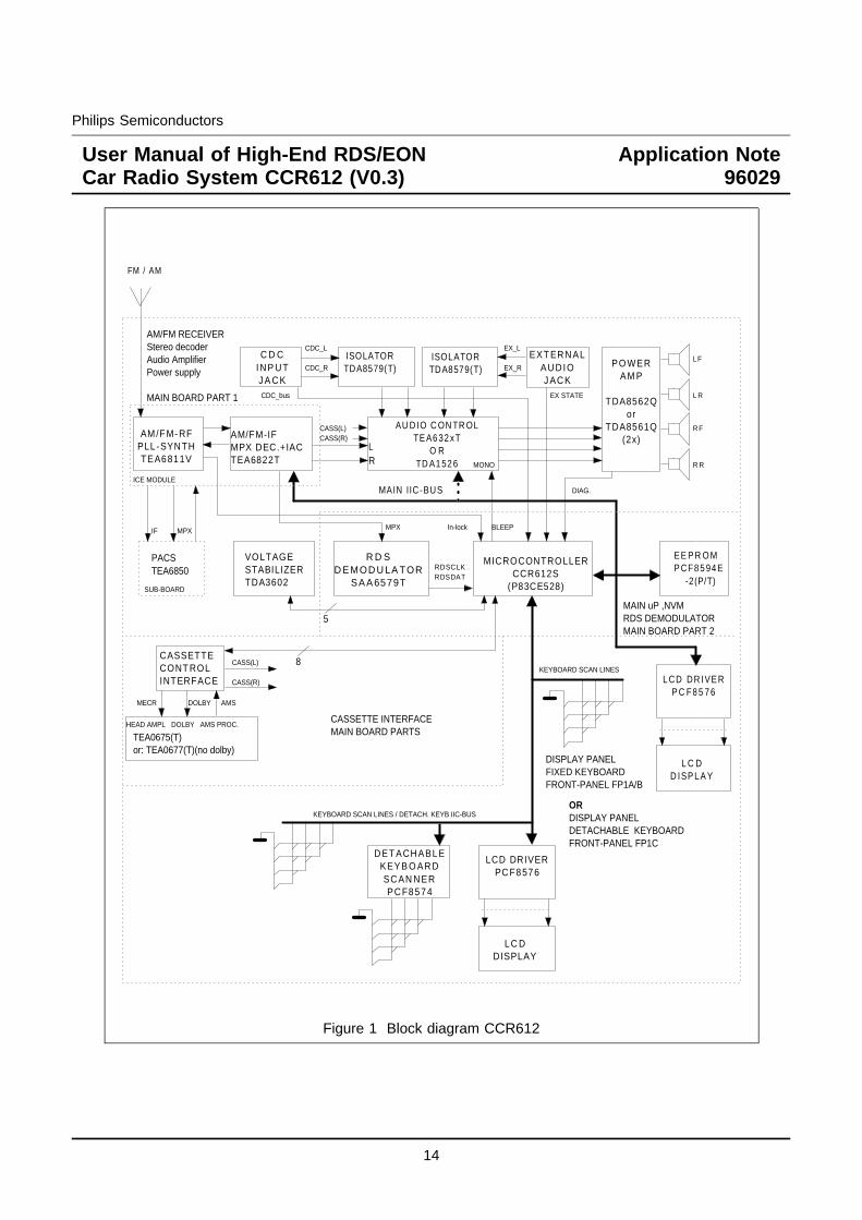
2 HARDWARE CONFIGURATION2.1 Block diagram CCR612Figure 1 shows the block diagram of the high-end computer controlled RDS car radio system CCR612.As can be seen in the block diagram, the system can either be equipped with a fixed keyboard or with adetachable keyboard. The detachable keyboard version of the system still allows some keys to be realisedas fixed keyboard keys. Furthermore a choice exists with respect to the following system parts:
- Power amplifier ( 2 speaker / 4 speaker / output power)- Sound control (Potentiometer control / I2C control)
This hardware description only describes the use of the sofac TEA6320.
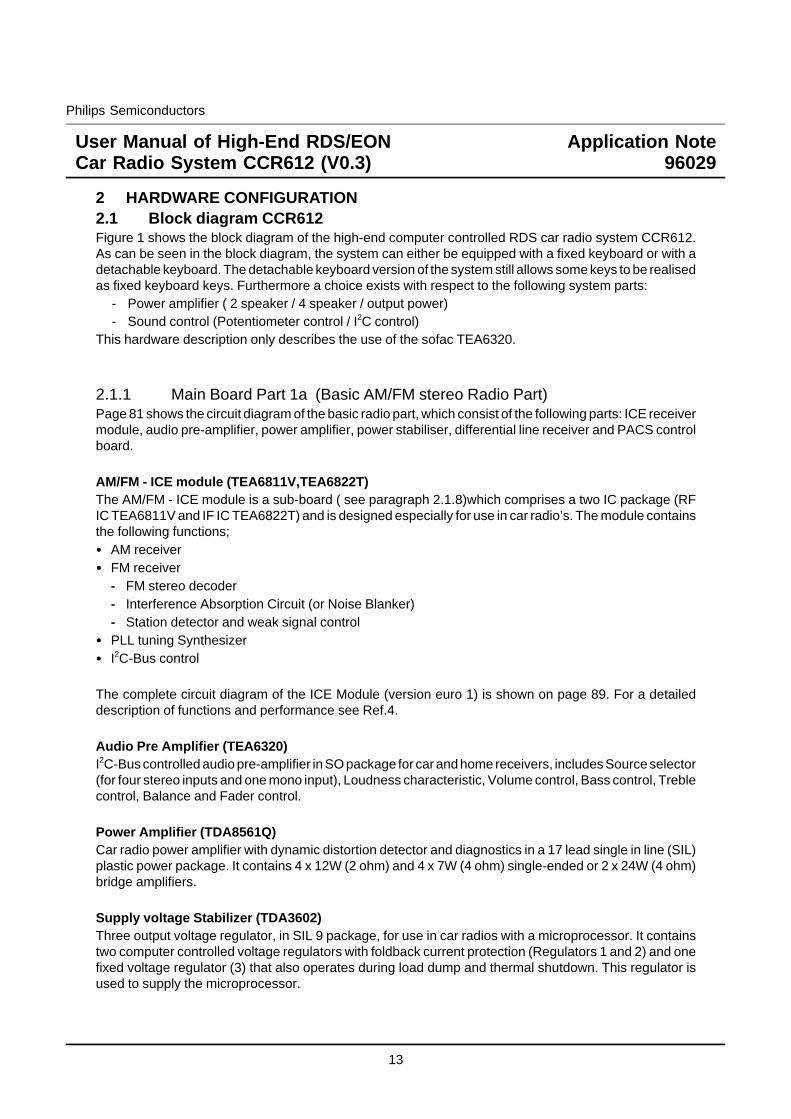
2.1.1 Main Board Part 1a (Basic AM/FM stereo Radio Part)Page 81 shows the circuit diagram of the basic radio part, which consist of the following parts: ICE receivermodule, audio pre-amplifier, power amplifier, power stabiliser, differential line receiver and PACS controlboard.
AM/FM - ICE module (TEA6811V,TEA6822T)The AM/FM - ICE module is a sub-board ( see paragraph 2.1.8)which comprises a two IC package (RFIC TEA6811V and IF IC TEA6822T) and is designed especially for use in car radio’s. The module containsthe following functions;
AM receiverFM receiver- FM stereo decoder- Interference Absorption Circuit (or Noise Blanker)- Station detector and weak signal controlPLL tuning SynthesizerI2C-Bus control
The complete circuit diagram of the ICE Module (version euro 1) is shown on page 89. For a detaileddescription of functions and performance see Ref.4.
Audio Pre Amplifier (TEA6320)I2C-Bus controlled audio pre-amplifier in SO package for car and home receivers, includes Source selector(for four stereo inputs and one mono input), Loudness characteristic, Volume control, Bass control, Treblecontrol, Balance and Fader control.
Power Amplifier (TDA8561Q)Car radio power amplifier with dynamic distortion detector and diagnostics in a 17 lead single in line (SIL)plastic power package. It contains 4 x 12W (2 ohm) and 4 x 7W (4 ohm) single-ended or 2 x 24W (4 ohm)bridge amplifiers.
Supply voltage Stabilizer (TDA3602)Three output voltage regulator, in SIL 9 package, for use in car radios with a microprocessor. It containstwo computer controlled voltage regulators with foldback current protection (Regulators 1 and 2) and onefixed voltage regulator (3) that also operates during load dump and thermal shutdown. This regulator isused to supply the microprocessor.
13
Philips Semiconductors
User Manual of High-End RDS/EONCar Radio System CCR612 (V0.3)
Application Note96029
AM/FM-IFMPX DEC.+IACTEA6822T
LR
L C DD ISP L A Y
MAIN IIC -BUS
VOLTAGESTABILIZERTDA3602
FM / AM
CASSETTECONT ROLINTERFACE L CD DR IVE R
P C F8 5 7 6
R D SD E MOD U LA TOR
S A A 6579T
RDSCLKRDSDAT
E E P R O MP CF8 5 94 E -2(P/T)
MICROCONTROLLERCCR612S
(P83CE528)
AM/F M- RFPLL-SYN THTEA6811V
AU DIO C ON TR OLTE A6 32 xT
O RTD A1 52 6
PO WERAM P
TDA8562Qor
TDA8561Q(2x)
C D CINP U TJ A C K
ISOLATORTDA8579(T)
CASS(L)CASS(R)
LF
L R
R F
R R
CDC_L
CDC_R
CASS(L)
CASS(R)
TEA0675(T)or: TEA0677(T)(no dolby)
MAIN uP ,NVMRDS DEMODULATOR MAIN BOARD PART 2
DISPLAY PANELFIXED KEYBOARDFRONT-PANEL FP1A/B
KEYBOARD SCAN LINES
EX STATE
8
LC DDISPLAY
LCD DRIVERPC F8576
D ET ACH ABLEKEYB O AR DSC AN N ERPC F8574
KEYBOARD SCAN LINES / DETACH. KEYB IIC-BUSORDISPLAY PANELDETACHABLE KEYBOARDFRONT-PANEL FP1C
HEAD AMPL DOLBY AMS PROC.
AMSDOLBYMECR
CASSETTE INTERFACEMAIN BOARD PARTS
EXT ER N ALAU D I OJ AC K
EX_L
EX_RISOLATORTDA8579(T)
CDC_bus
5
PACSTEA6850
SUB-BOARD
MPXIF MPX
MONO
DIAG.
BLEEPIn-lock
ICE MODULE
AM/FM RECEIVERStereo decoderAudio AmplifierPower supply
MAIN BOARD PART 1
Figure 1 Block diagram CCR612
14
Philips Semiconductors
User Manual of High-End RDS/EONCar Radio System CCR612 (V0.3)
Application Note96029
Isolator ( Differential Line Receiver, TDA8579T)Dual common-mode rejection differential line receiver with 0 dB gain and low distortion. This device isintended to be used to receive line inputs in audio applications that require a high level of common-moderejection. The device is encapsulated in an 8-pin SO or DIL package. In this set the isolator is usedbetween the external input and source selector input. Both the external input plug circuit and theCD-changer input circuit are equipped with an isolator.
PACS - Sub Board (TEA6850)PACS controls the I.F. Selectivity / Bandwidth to avoid receiving problems due to near adjacent channels(especially for Europe, spacing of 100 kHz is not an exception). In order to show the improvements of theselectivity and dynamic behaviour of the radio by the use of PACS an ON/OFF switch has been used onthe front panel.A complete circuit diagram of the PACS board is shown on page 94 and for description of the functions,alignment and performance see Ref.5.
2.1.2 Main Board Part 1b (Optional Power Amplifier, 2 x TDA8561Q)Page 82 shows the previous circuit diagram (paragraph 2.1.1 Basic AM/FM stereo Radio Part) equippedwith circuits for 4 x 24W (4 ohm) audio output power.
Power Amplifier (2 x TDA8561Q)Single circuit configuration 2 x 24W (4 ohm) bridge amplifiers, package SIL 17 pins Quil.
2.1.3 Main Board Part 1c (Optional Source Sel. & Audio Contr.HEF4052B/TDA1526)
Page 83 shows the circuit diagram from paragraph 2.1.1 (Basic AM/FM stereo Radio Part) equipped withthe DC controlled audio pre-amplifier (TDA1526) and a source selector circuit (HEF4052B).This set-upis used in case potentiometer control for volume and tone is desired.
Audio Pre-Amplifier and DC Control (TDA1526).An active stereo,tone/volume control for car radios. It includes functions for bass and treble, control,volume control with built in contour (can be switched off) and balance.All these functions can be controlleddirect by DC voltages or via single linear potentiometers.
Source selector circuit (HEF4052B).The HEF4052B is a dual 4 channel analogue multiplexer/demultiplexer with common channel select logic.In this case used for four stereo inputs: radio, cassette and external input.
15
Philips Semiconductors
User Manual of High-End RDS/EONCar Radio System CCR612 (V0.3)
Application Note96029
2.1.4 Main Board Part 2a ( Micro-controller, EEPROM and RDS Demodulator)Page 84 shows the circuit diagram of the RDS Demodulator, Micro controller (which combines all radiocontrol functions as well as RDS decoding) and EEPROM.
Microcontroller (P83CE528EFB)Main microcontroller (CCR612S), a derivative of the 8051 micro-controller family with an 8-bit CPU, 32Kbytes ROM, 512 bytes RAM and four 8-bits I/O ports in a 44-pins QFP package.
EEPROM (PCF8594E-2P/T)The PCF8594E is a 512 byte, 5V Electrically Erasable Programmable Read Only Memory (EEPROM) thatcan be 100,000 times re-written. I2C-bus controlled.
RDS Demodulator (SAA6579T)RDS Demodulator IC, which includes the 57 kHz band-pass-filter, to generate the RDS data out of theMPX signal.
2.1.5 Main Board Part 2b (Detachable Front)Page 85 shows the previous circuit diagram (paragraph 2.1.4) of the micro controller board extended withthe possibility to use a detachable front panel.
2.1.6 Main Board Part 3 (Cassette Interface including Dolby B*)Page 86 shows the circuit diagram of the cassette interface circuit for the Philips cassette deck P6-29/3.The circuit is based on the TEA0675, Dual Dolby* B-type noise reduction circuit for playback applications.
The TEA0675 includes head and equalization amplifiers with electronically switchable time constants.Furthermore the TEA0675 includes electronically switchable inputs for tape drives with reverse heads.This device also detects pauses of music in the AMS (Automatic Music Search) scan mode.
16
Philips Semiconductors
User Manual of High-End RDS/EONCar Radio System CCR612 (V0.3)
Application Note96029
2.1.7 Front Panels2.1.7.1 Front Panel Part FP-1a (Key and Display panel)Page 87 shows the circuit diagram of the key and display panel.
LCD Driver (PCT8576CT)The PCF8576 is a peripheral device which interfaces to almost any liquid crystal display (LCD) having lowmultiplex rates. It generates the drive signals for any static or multiplex LCD containing up to four backplanes and up to 40/24 segments and can easily be cascaded for larger LCD applications. I2C-buscontrolled.
2.1.7.2 Front Panel Part FP-1b (Detachable Front Version).Page 88 shows the circuit diagram of the detachable keyboard front. The circuit includes an I/O expanderPCF8574, the keyboard and LCD display unit are placed on the detachable front controlled by a secondI2C bus. Eight contacts are required to connect the detachable front to the radio. Furthermore there is afixed key-board with a limited number of keys included. That means it is possible to use a combination ofdetachable keys and fixed keys (for circuit example see page 85).
2.1.8 Diagram ICE module.
Standard Version EURO 1
Page 89 shows the complete circuit diagram of the ICE AM/FM tuner module version Euro 1.The Standard Euro 1 module is intended for European frequency ranges.
FM 87.5 to 108.0 MHzAM (MW) 531 to 1629 kHzAM (LW) 144 to 288 kHz
The module contains the IC’s TEA6811V and TEA6822T with the following main functions;
TEA6811 - AM RF TEA6822 - 2nd AM mixer- AM mixer - 2nd FM mixer- FM mixer - AM/FM - IF amplifier- AM/FM oscillator - AM and FM demodulator- Tuning synthesizer - x-tal oscillator (61.5 MHz)- I2C-Bus - Stereo Decoder and IAC
- Station (stop) detector- Weak signal processing- Multi Path Detector- I2C-Bus
17
Philips Semiconductors
User Manual of High-End RDS/EONCar Radio System CCR612 (V0.3)
Application Note96029
EURO 2, USA 1 and JAPAN 1 ICE MODULE VERSIONS.
By slight circuit modifications of the standard module (EURO 1), matched module versions with betterperformance for e.g. USA an Japan can be derived. The needed modifications for the different modulesare:
Module Version Modifications.
Euro 1 Non
Euro 2 (including S.W.) A short wave transformer i.s.o. L8 and C29
USA 1 L15 short circuitedC2 10pF i.s.o. 5p6C72 6p8 deletedR18 1 Mohm i.s.o. 220 KohmR54, in parallel with C26 (1uF)C61 10 nF i.s.o. 6n8C62 10 nF i.s.o. 6n8Z1 SFR450H i.s.o. SFP 450HZ3 SFE 10.7 MS3 G-A 220 kHz i.s.o. SFE10.7 MS3 A 10k-AZ2 & Z4 SFE 10.7 MS2 G-A 180 kHz i.s.o. SFE10.7 MS3 A 10k-AR41 (pre-set adjust) replaced by resistor of 68 Kohm.R44 120 Kohm i.s.o. 82 Kohm.
Japan 1 C7 47 pF i.s.o. 180pFC9 deletedD3 BB814 selection i.s.o. BB804
2.1.9 Diagram PACS Sub BoardPage 94 shows the diagram of the PACS Sub-Board using the TEA6850. For circuit description,performance and PCB lay out see application note Ref.5.
2.1.10 PCB LAY-OUTS of CCR612 sample Version D.CCR612/Mainboard PCB lay-out TOP side Copper (p. 90, fig. a) / Components (non SMD) (p. 90, fig. b)CCR612/Mainboard PCB lay-out BOTTOM side Copper(p. 91, fig. c) / SMD Components (p. 91, fig.d)ICE module board PCB lay-out TOP side Copper(p. 92, fig. a) /Components (non SMD) (p. 92, fig. b)ICE module board PCB lay-out Bottom side Copper(p. 92, fig. c) / SMD Components (p. 92, fig. d)Front panel PCB lay-out Top side Copper (p. 93, fig. a) / Components (non SMD) (p. 93, fig. b)Front panel PCB lay-out Bottom side Copper (p. 93, fig. c) / SMD Components (p. 93, fig. d).
18
Philips Semiconductors
User Manual of High-End RDS/EONCar Radio System CCR612 (V0.3)
Application Note96029
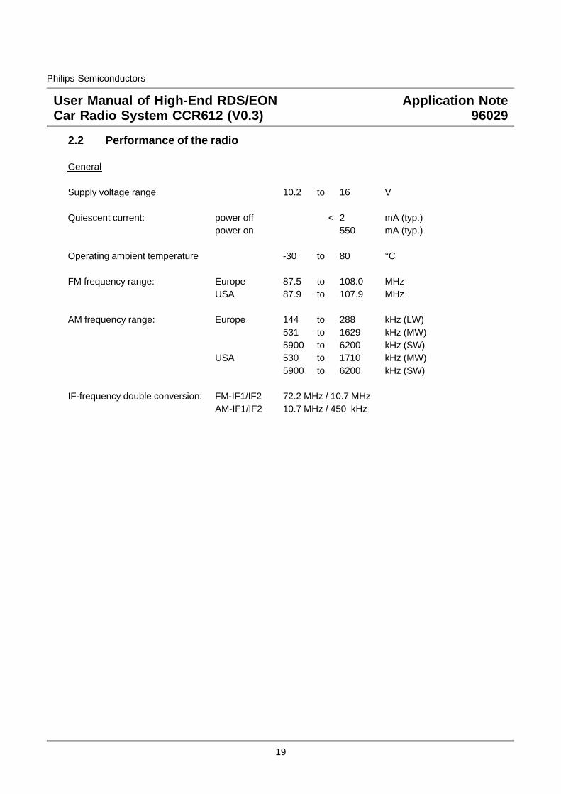
2.2 Performance of the radio
General
Supply voltage range 10.2 to 16 V
Quiescent current: power off < 2 mA (typ.)power on 550 mA (typ.)
Operating ambient temperature -30 to 80 °C
FM frequency range: Europe 87.5 to 108.0 MHzUSA 87.9 to 107.9 MHz
AM frequency range: Europe 144 to 288 kHz (LW)531 to 1629 kHz (MW)5900 to 6200 kHz (SW)
USA 530 to 1710 kHz (MW)5900 to 6200 kHz (SW)
IF-frequency double conversion: FM-IF1/IF2 72.2 MHz / 10.7 MHzAM-IF1/IF2 10.7 MHz / 450 kHz
19
Philips Semiconductors
User Manual of High-End RDS/EONCar Radio System CCR612 (V0.3)
Application Note96029
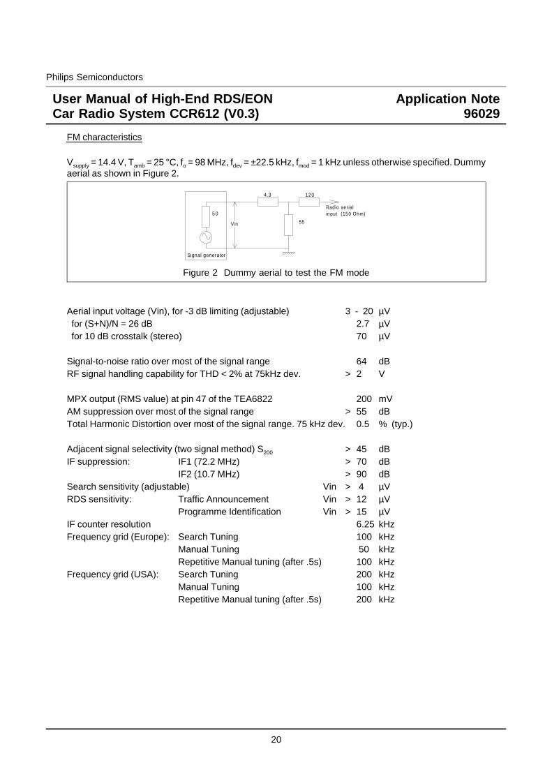
FM characteristics
Vsupply = 14.4 V, Tamb = 25 °C, fo = 98 MHz, fdev = ±22.5 kHz, fmod = 1 kHz unless otherwise specified. Dummyaerial as shown in Figure 2.
55
1204.3
5 0
Signal generator
Radio aer ialinput (150 Ohm)
Vin
Figure 2 Dummy aerial to test the FM mode
Aerial input voltage (Vin), for -3 dB limiting (adjustable) 3 - 20 µVfor (S+N)/N = 26 dB 2.7 µVfor 10 dB crosstalk (stereo) 70 µV
Signal-to-noise ratio over most of the signal range 64 dBRF signal handling capability for THD < 2% at 75kHz dev. > 2 V
MPX output (RMS value) at pin 47 of the TEA6822 200 mVAM suppression over most of the signal range > 55 dBTotal Harmonic Distortion over most of the signal range. 75 kHz dev. 0.5 % (typ.)
Adjacent signal selectivity (two signal method) S200 > 45 dBIF suppression: IF1 (72.2 MHz) > 70 dB
IF2 (10.7 MHz) > 90 dBSearch sensitivity (adjustable) Vin > 4 µVRDS sensitivity: Traffic Announcement Vin > 12 µV
Programme Identification Vin > 15 µVIF counter resolution 6.25 kHzFrequency grid (Europe): Search Tuning 100 kHz
Manual Tuning 50 kHzRepetitive Manual tuning (after .5s) 100 kHz
Frequency grid (USA): Search Tuning 200 kHzManual Tuning 100 kHzRepetitive Manual tuning (after .5s) 200 kHz
20
Philips Semiconductors
User Manual of High-End RDS/EONCar Radio System CCR612 (V0.3)
Application Note96029
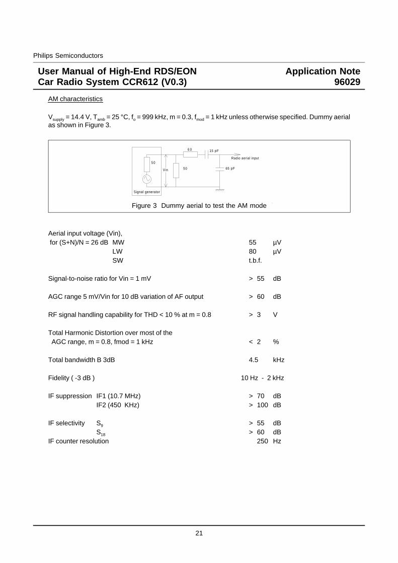
AM characteristics
Vsupply = 14.4 V, Tamb = 25 °C, fo = 999 kHz, m = 0.3, fmod = 1 kHz unless otherwise specified. Dummy aerialas shown in Figure 3.
50
6 0
5 0
Signal generator
Vin
Radio aerial input
65 pF
15 pF
Figure 3 Dummy aerial to test the AM mode
Aerial input voltage (Vin),for (S+N)/N = 26 dB MW 55 µV
LW 80 µVSW t.b.f.
Signal-to-noise ratio for Vin = 1 mV > 55 dB
AGC range 5 mV/Vin for 10 dB variation of AF output > 60 dB
RF signal handling capability for THD < 10 % at m = 0.8 > 3 V
Total Harmonic Distortion over most of theAGC range, m = 0.8, fmod = 1 kHz < 2 %
Total bandwidth B 3dB 4.5 kHz
Fidelity ( -3 dB ) 10 Hz - 2 kHz
IF suppression IF1 (10.7 MHz) > 70 dBIF2 (450 KHz) > 100 dB
IF selectivity S9 > 55 dBS18 > 60 dB
IF counter resolution 250 Hz
21
Philips Semiconductors
User Manual of High-End RDS/EONCar Radio System CCR612 (V0.3)
Application Note96029
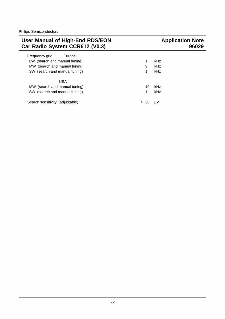
Frequency grid EuropeLW (search and manual tuning) 1 kHzMW (search and manual tuning) 9 kHzSW (search and manual tuning) 1 kHz
USAMW (search and manual tuning) 10 kHzSW (search and manual tuning) 1 kHz
Search sensitivity (adjustable) > 20 µV
22
Philips Semiconductors
User Manual of High-End RDS/EONCar Radio System CCR612 (V0.3)
Application Note96029
3 SHORT SPECIFICATION
TuningFrequency bands:Optionally the following frequency bands are used:
FM: 87.50 - 108.00 MHz (50 / 100 kHz steps) MW: 531 - 1629 kHz (9 kHz steps) For application in EuropeLW: 144 - 288 kHz (1 kHz steps) SW: 5.9 - 6.2 MHz (1 kHz steps)
FM: 87.90 - 107.90 MHz (100 / 200 kHz steps) MW: 530 - 1710 kHz (10 kHz steps) For application in USASW: 5.9 - 6.2 MHz (1 kHz steps)
PLL tuning principle
Manual tuning up / downFirst one step, next after 0.5 seconds. Fast repetition at 12.5 times per second.
Local/Dx switchingThe Local/Dx feature controls the search sensitivity. Default after switching on is always Dx.In the TEA6811 a tuner attenuator for the FM-band is incorporated.
Search tuning up / downSensitivity is controlled by Local/Dx. If after one complete band sweep in Local mode no station isfound, the radio switches automatically to Dx. During search tuning the running frequency is displayedand the radio is muted.
Frequency ScanContinuous automatic search tuning, pausing for 6 seconds on every station.
AST (Automatic Store Tuning) for FM and MW bandAST switches to FM-AST or MW-AST band, searches for the 6 strongest transmitters in the band andstores them in the AST programme preset memory. In FM, duplication of PI codes will be avoided.
Programme preset memoryFor each band (FM1, FM2, MW, LW, SW (49m), FM-AST and MW-AST) 6 programme presets and a"manual" frequency are stored. In FM, additional RDS information is stored: PI code (ProgrammeIdentification), PS name (Programme Service), AF list (Alternative Frequencies) and AF follow modeon/off.Whenever another band is selected, the radio reverts to the last frequency tuned to in the new band(this can be either a preset frequency or a manually tuned frequency).
Programme preset up / down controlProgramme presets can be stored and recalled by two key control (up and down) or by 6 separatepreset keys.
23
Philips Semiconductors
User Manual of High-End RDS/EONCar Radio System CCR612 (V0.3)
Application Note96029
AF follow modeWhen AF follow mode is on, the set will regularly measure the signal strength of alternative frequenciesand compare it with the current station. If an alternative frequency offers better quality, the radio willswitch over and update the alternative frequency list. The measuring scheme is designed to causeminimum noticeable disturbance for the listener. The interval time between two measurements dependson the signal quality.
Intelligent preset programme recallIf an FM programme preset with a known PI code is recalled, the primary frequency and all alternativefrequencies stored in the programme preset memory are examined. The frequency with the best signalquality broadcasting the correct PI code will be selected. Only when the programme is not found on oneof the AFs, after 6 seconds a search is started for a station with a proper PI code.
TA modeIn TA mode the radio only searches for transmitters that transmit the RDS traffic programme on thesame station or on EON linked stations. The radio will automatically start a search when switching TAmode on and the current station is not a traffic station.
PTY scan modeIn PTY scan mode the radio searches for transmitters that transmit the user-selected PTY code.Dependent on the factory option USA/Europe the RBDS PTY-table or the RDS PTY-table is used. OnlyEnglish PTY messages are available.
Last status memory: band, frequency, PI code, AF follow mode on/off status and TA mode on/off statusare stored in memory. This status is recalled during switch on.
RDSBit, block and group synchronisation. (inclusive RBDS E-block detection).
Data collection and decoding of:- PI, Programme Identification code- AF, Alternative Frequencies- TP, Traffic Programme- TA, Traffic Announcement- PS, Programme Service name- PTY, Programme TYpe- EON, Enhanced Other Network
AF follow mode using PI and AF (see also Tuning).
Display of the programme service name in 8 alpha-numeric characters (PS name).
Display of AF, TP, TA, PTY, EON and Regional mode status via icons.
Regional mode on/off switching. When Regional mode is on, the radio will, during AF switching, onlyswitch over to stations with exactly the same PI-code. When Regional mode is off, the radio will also
24
Philips Semiconductors
User Manual of High-End RDS/EONCar Radio System CCR612 (V0.3)
Application Note96029
switch over to stations broadcasting regional variants of the original station. (so called "generic" or"family" PI codes). For USA application (RBDS) the regional function will only work for PI codes aboveB000hex. PI codes below B000hex do not have regional variants. Af switching is only allowed to stationswith exactly the same PI code.
Break-in of traffic announcements is possible if the TA option is switched on. The PTY alarm messagesbreak-in always. Break in is possible even when the radio is muted or in CD-changer / cassette /external mode.
User ControlUp to 27 Local control keys on either a fixed, a detachable keyboard or a combination. Triangular matrixusing 7 lines.
Detachable frontOptionally, the keyboard and the LCD display unit can be placed on a detachable front controlled bya 2nd I2C bus. Only 5 contacts are required to connect the detachable front (6 if it hosts also the powerkey). No extra hardware is required to detect its presence.
EONIf the TA option is on, switch temporarily to an other station if EON information indicates a trafficannouncement on another network even when the radio is muted or in CD-changer / cassette / externalmode.
Maintain lists of alternative frequencies of other stations stored in preset memory with informationreceived via EON on the currently tuned station.
Display by means of an icon whether EON data is received and whether an EON traffic announcementis broadcast.
Display143 Segment LCD with Umlaut (ü) characters, 1:4 multiplexed divided into:
8 Alphanumeric characters + decimal point are used to display:- Band and frequency (Example: "FM 103.50")- Indication "BALANCE", "FADER", "TREBLE", "BASS" and their value.- RDS programme service name (PS) in 8 alphanumeric characters.- RDS programme type (PTY)- "MUTE", in case the user mutes the radio, cassette or external- Cassette mode function such as "PLAY >", "CAS WIND", etc.- CD-changer messages such as "CD 01.23" , "CHANGER " etc.
7 Segment display for the current programme preset number.
25
Philips Semiconductors
User Manual of High-End RDS/EONCar Radio System CCR612 (V0.3)
Application Note96029
15 Icons for display of:- ST On when stereo pilot signal is detected and the radio is not in forced mono mode.- AST On when AST band is selected.- SCAN On when in Frequency scan mode.- AF On when AF follow mode is enabled (see also Tuning), flashing if no RDS data
received.- TA On in TA mode and flashing during a traffic announcement in progress.- TP On when a traffic station is received, flashing when the station is not a traffic station
and TA mode is on.- PTY On when a PTY code is received, flashing during PTY search.- DOLBY On in cassette mode when dolby is on.- MTL On in cassette mode when metal/chrome is selected.- AMS On in cassette mode when AMS is on.- REG On when the radio is in regional mode (see also RDS)- EON On when EON data is received, flashing during an EON traffic announcement.- LOC On when the radio is in Local mode (see also Tuning)- LOUD On when Loudness is on.- CLIP On when clipping is detected and clipping control is active.
Non Volatile Memory512 bytes EEPROM. The following information is stored in NVM:
System status e.g.: band, audio source (radio / CD-changer / cassette / external).For each band FM1, FM2, FM-AST, MW, MW-AST, LW, SW(49m) : 6 preset frequencies, one non-preset frequency and the last used preset number.For each FM preset:- PI-code- PS Name- AF List (9 AF’s)- AF follow mode on/off.Audio controls: volume, bass, treble, balance, fader and loudness.Preprogramming EEPROMAt power-on the contents of the NVM is checked, when a non-initialized EEPROM is detected, theEEPROM will be preprogrammed with default values.Appendix II lists the default values written to NVM during initialization.
SoundVolume, bass, treble, balance and fader control with VOL-UP / VOL-DOWN keys.Analog control select key to cycle through bass, treble, balance and fader.Mute function.Automatic muting during tuning and AST search (silent tuning).Break-in of traffic announcements and PTY-alarm messages (at increased volume level, which is userprogrammable) when the radio is muted or in cassette / external mode.Loudness function.
26
Philips Semiconductors
User Manual of High-End RDS/EONCar Radio System CCR612 (V0.3)
Application Note96029
Sound settings are stored at switch-off and recalled at switch-on."Bleep" tone to confirm user actions such as storing a programme preset, entering AST mode, etc.Mono / stereo function.Output pins for mute, loudness and traffic announcement, for use with conventional audio controlcircuitry.Automatic mute of radio during "Phone mute" detection.
Power-amplifierPower-amplifiers with diagnostic facilities* 1 × TDA8561Q amplifier for 4 × 12 W ( 2Ω load) or 4 × 7 W or 2 × 24 W bridged application. (both at
4Ω load)* 1 × TDA8562Q amplifier for 4 × 12 W ( 2Ω load) or 4 × 7 W (4Ω load)* 2 × TDA8561Q amplifier for 4 × 24 W bridged application. (4Ω load)Diagnostic control:* short-circuit or too high temperature detection, display an error message* signal clipping, via an icon and stepwise decrease of bass and or volumeOptional conventional power-amplifiers (without diagnostics) can be used such as two TDA1552Q for4 × 22 W, one TDA1554Q for 4 × 11 W (2Ω load) or 4 × 6 W (4Ω load) or one TDA1552Q 2 × 22 W ina BTL stereo configuration.
OptionsDiode programmable- Detachable front- Available frequency bands- Static on/off switch- Frequency band limits and tuning grid for different parts of the world. This option also selects
between RDS (Europe) and RBDS (USA).
User programmable- 2 / 4 Loudspeakers- Loudness on / off- TA volume level
Automatically detected- Digital sound control chip or conventional audio control circuitry- Loudness- AMS - Dolby Cassette deck functions- MTL - Presence of the CD-changer (check during power-on)- Availability of a power amplifier with diagnostics facilities
27
Philips Semiconductors
User Manual of High-End RDS/EONCar Radio System CCR612 (V0.3)
Application Note96029
Power connectionsContinuous power supply input. Normally connected directly to the car battery. All supply power isdrawn from this supply.Ignition key input. Normally connected to the accessory contact of the ignition switch. Used only forswitching the radio on/off. This input is also used when the static on/off switch option is chosen insteadof the momentary on/off key.
Switching on/offRecall of last system status (e.g.: frequency, band, sound control settings, RDS status and last selectedaudio source).Switch on by:- Power key, can be static or momentary.- Ignition contact (after the set was switched off by turning the ignition contact off).Switch off by:- Power key, can be static or momentary.- Ignition contact.- Removal of detachable keyboard.When switched on while the ignition contact is (and remains) off, the set will automatically switch offafter 60 minutes.The radio will switch on again when switched off due to a power dip during engine start.
CD-changerRadio/CD-changer/Cassette/External mode key.Disc up/down keys for selecting the next/previous disc.Track up/down keys for selecting the next/previous track.Fast forward/reverse keys for jumping some grooves forward/backward.Shuffle on/off key, for playing the tracks in random order. (The user can make a selection betweentracks on the current disc only or tracks on all discs.)Repeat on/off key, for repetitive play of the current track or the current disc.Intro-scan key. When Intro-scan mode is on, each track of the current disc or the first track of every disc(user selectable) are played for 10 seconds in successive order.
28
Philips Semiconductors
User Manual of High-End RDS/EONCar Radio System CCR612 (V0.3)
Application Note96029
CassetteAutomatically switches to cassette mode after insertion of a tapeInterfaces with a mechanically controlled cassette deckPlay/wind mode detectionPlay direction detection for auto-reverse cassette decksCassette solenoid controlAMS pause detection for full AMS controlRadio sound during cassette windingMTL on/off keyDOLBY on/off keyAMS on/off keyCD-changer/Cassette/Radio/External mode keyOptional source switching to external mode (external plug is in) or always to radio mode (option diodeD6 is present) when the tape is ejected.
External audio input:Automatically switches to external audio source when a connector is inserted.CD-changer/External/radio/Cassette mode key.Optional source switching to cassette mode (tape is in) or always to radio mode (option diode D6 ispresent) when the external plug is removed.
29
Philips Semiconductors
User Manual of High-End RDS/EONCar Radio System CCR612 (V0.3)
Application Note96029
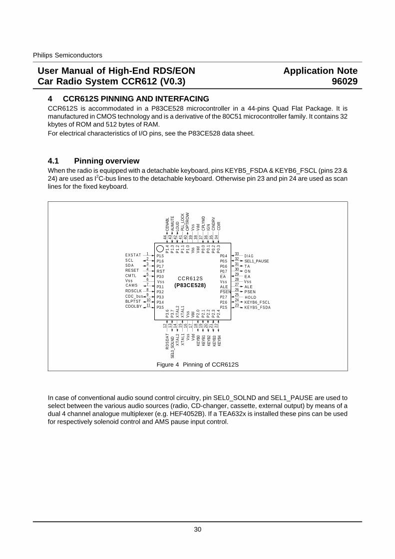
4 CCR612S PINNING AND INTERFACINGCCR612S is accommodated in a P83CE528 microcontroller in a 44-pins Quad Flat Package. It ismanufactured in CMOS technology and is a derivative of the 80C51 microcontroller family. It contains 32kbytes of ROM and 512 bytes of RAM.For electrical characteristics of I/O pins, see the P83CE528 data sheet.
4.1 Pinning overviewWhen the radio is equipped with a detachable keyboard, pins KEYB5_FSDA & KEYB6_FSCL (pins 23 &24) are used as I2C-bus lines to the detachable keyboard. Otherwise pin 23 and pin 24 are used as scanlines for the fixed keyboard.
1234567891011
12 1413 15 16 17 18 19 20 21 22
23
2524
2627282930313233
3435363738394041424344
P1.5P1.6
RST
P3.1P3.2P3.3P3.4P3.5
P3.
6P
3.7
XTA
L2X
TAL1
P2.
0P
2.1
P2.
2P
2.3
P2.
4
P2.5P2.6P2.7PSENALE
EAP0.7P0.6P0.5P0.4
P0.
3P
0.2
P0.
1P
0.0
Vdd
P1.
0P
1.1
P1.
2P
1.3
P1.
4
E X S T A TS C LSD A P1.7RESETCM TL
CDC_ b u sBLPTSTCDOLBY K E Y B 5 _ F S DA
PSENALE
E AO NT ASEL1_PAUSED I A G
Vdd CD
IRC
IND
RV
IGN
CPL
YWD
LOU
DAU
MU
TEC
ENAB
L
XTA
L2X
TAL1
SEL0
_SO
LND
KEYB
0
Vss
Vss
KEYB6_F SC L
RD
SD
AT
RDSCLK
Vs sP3.0V s s
Vss
Vss
Vs sV s s
Vdd
Vdd
KEYB
1KE
YB2
KEYB
4
H O LD
OP
TR
OW
(P83CE528)CC R61 2S
C A M S
PLL_
LOC
K
KEYB
3
Figure 4 Pinning of CCR612S
In case of conventional audio sound control circuitry, pin SEL0_SOLND and SEL1_PAUSE are used toselect between the various audio sources (radio, CD-changer, cassette, external output) by means of adual 4 channel analogue multiplexer (e.g. HEF4052B). If a TEA632x is installed these pins can be usedfor respectively solenoid control and AMS pause input control.
30
Philips Semiconductors
User Manual of High-End RDS/EONCar Radio System CCR612 (V0.3)
Application Note96029
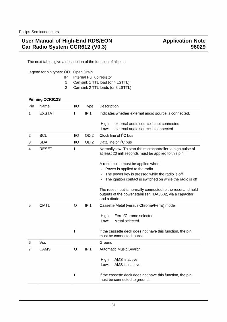
The next tables give a description of the function of all pins.
Legend for pin types: OD Open DrainIP Internal Pull up resistor1 Can sink 1 TTL load (or 4 LSTTL)2 Can sink 2 TTL loads (or 8 LSTTL)
Pinning CCR612S
Pin Name I/O Type Description
1 EXSTAT I IP 1 Indicates whether external audio source is connected.
High: external audio source is not connectedLow: external audio source is connected
2 SCL I/O OD 2 Clock line of I2C bus
3 SDA I/O OD 2 Data line of I2C bus
4 RESET I Normally low. To start the microcontroller, a high pulse ofat least 20 milliseconds must be applied to this pin.
A reset pulse must be applied when:- Power is applied to the radio- The power key is pressed while the radio is off- The ignition contact is switched on while the radio is off
The reset input is normally connected to the reset and holdoutputs of the power stabiliser TDA3602, via a capacitorand a diode.
5 CMTL O
I
IP 1 Cassette Metal (versus Chrome/Ferro) mode
High: Ferro/Chrome selectedLow: Metal selected
If the cassette deck does not have this function, the pinmust be connected to Vdd.
6 Vss Ground
7 CAMS O
I
IP 1 Automatic Music Search
High: AMS is activeLow: AMS is inactive
If the cassette deck does not have this function, the pinmust be connected to ground.
31
Philips Semiconductors
User Manual of High-End RDS/EONCar Radio System CCR612 (V0.3)
Application Note96029
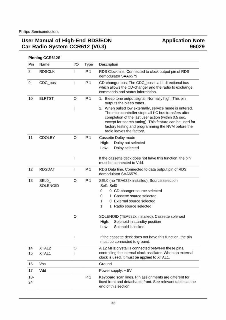
Pinning CCR612S
Pin Name I/O Type Description
8 RDSCLK I IP 1 RDS Clock line. Connected to clock output pin of RDSdemodulator SAA6579
9 CDC_bus I IP 1 CD-changer bus. The CDC_bus is a bi-directional buswhich allows the CD-changer and the radio to exchangecommands and status information.
10 BLPTST O
I
IP 1 1. Bleep tone output signal. Normally high. This pinoutputs the bleep tones.
2. When pulled low externally, service mode is entered.The microcontroller stops all I2C bus transfers aftercompletion of the last user action (within 0.5 sec.except for search tuning). This feature can be used forfactory testing and programming the NVM before theradio leaves the factory.
11 CDOLBY O
I
IP 1 Cassette Dolby modeHigh: Dolby not selectedLow: Dolby selected
If the cassette deck does not have this function, the pinmust be connected to Vdd.
12 RDSDAT I IP 1 RDS Data line. Connected to data output pin of RDSdemodulator SAA6579.
13 SEL0_SOLENOID
O
O
I
IP 1 SEL0 (no TEA632x installed). Source selectionSel1 Sel00 0 CD-changer source selected0 1 Cassette source selected1 0 External source selected1 1 Radio source selected
SOLENOID (TEA632x installed). Cassette solenoidHigh: Solenoid in standby positionLow: Solenoid is locked
If the cassette deck does not have this function, the pinmust be connected to ground.
1415
XTAL2XTAL1
OI
A 12 MHz crystal is connected between these pins,controlling the internal clock oscillator. When an externalclock is used, it must be applied to XTAL1.
16 Vss Ground
17 Vdd Power supply: + 5V
18-24
IP 1 Keyboard scan lines. Pin assignments are different forfixed front and detachable front. See relevant tables at theend of this section.
32
Philips Semiconductors
User Manual of High-End RDS/EONCar Radio System CCR612 (V0.3)
Application Note96029
Pinning CCR612S
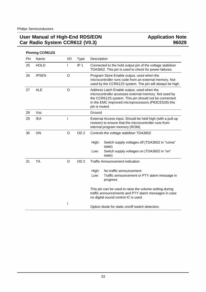
Pin Name I/O Type Description
25 HOLD I IP 1 Connected to the hold output pin of the voltage stabilizerTDA3602. This pin is used to check for power failures.
26 /PSEN O Program Store Enable output, used when themicrocontroller runs code from an external memory. Notused by the CCR612S system. The pin will always be high.
27 ALE O Address Latch Enable output, used when themicrocontroller accesses external memory. Not used bythe CCR612S system. This pin should not be connected.In the EMC improved microprocessors (P83CE528) thispin is muted.
28 Vss Ground
29 /EA I External Access input. Should be held high (with a pull-upresistor) to ensure that the microcontroller runs frominternal program memory (ROM).
30 ON O OD 2 Controls the voltage stabiliser TDA3602
High: Switch supply voltages off (TDA3602 in "coma"state)
Low: Switch supply voltages on (TDA3602 in "on"state)
31 TA O
I
OD 2 Traffic Announcement indication
High: No traffic announcementLow: Traffic announcement or PTY alarm message in
progress
This pin can be used to raise the volume setting duringtraffic announcements and PTY alarm messages in caseno digital sound control IC is used.
Option diode for static on/off switch detection.
33
Philips Semiconductors
User Manual of High-End RDS/EONCar Radio System CCR612 (V0.3)
Application Note96029
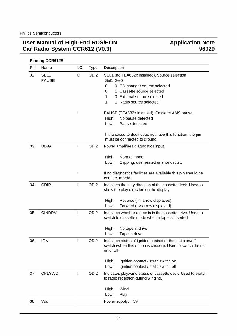
Pinning CCR612S
Pin Name I/O Type Description
32 SEL1_PAUSE
O
I
OD 2 SEL1 (no TEA632x installed). Source selectionSel1 Sel00 0 CD-changer source selected0 1 Cassette source selected1 0 External source selected1 1 Radio source selected
PAUSE (TEA632x installed). Cassette AMS pauseHigh: No pause detectedLow: Pause detected
If the cassette deck does not have this function, the pinmust be connected to ground.
33 DIAG I
I
OD 2 Power amplifiers diagnostics input.
High: Normal modeLow: Clipping, overheated or shortcircuit.
If no diagnostics facilities are available this pin should beconnect to Vdd.
34 CDIR I OD 2 Indicates the play direction of the cassette deck. Used toshow the play direction on the display
High: Reverse ( <- arrow displayed)Low: Forward ( -> arrow displayed)
35 CINDRV I OD 2 Indicates whether a tape is in the cassette drive. Used toswitch to cassette mode when a tape is inserted.
High: No tape in driveLow: Tape in drive
36 IGN I OD 2 Indicates status of ignition contact or the static on/offswitch (when this option is chosen). Used to switch the seton or off.
High: Ignition contact / static switch onLow: Ignition contact / static switch off
37 CPLYWD I OD 2 Indicates play/wind status of cassette deck. Used to switchto radio reception during winding.
High: WindLow: Play
38 Vdd Power supply: + 5V
34
Philips Semiconductors
User Manual of High-End RDS/EONCar Radio System CCR612 (V0.3)
Application Note96029
Pinning CCR612S
Pin Name I/O Type Description
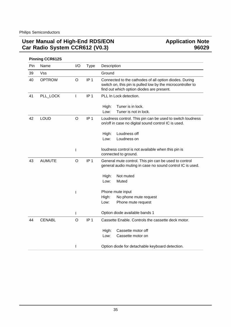
39 Vss Ground
40 OPTROW O IP 1 Connected to the cathodes of all option diodes. Duringswitch on, this pin is pulled low by the microcontroller tofind out which option diodes are present.
41 PLL_LOCK I IP 1 PLL In Lock detection.
High: Tuner is in lock.Low: Tuner is not in lock.
42 LOUD O
I
IP 1 Loudness control. This pin can be used to switch loudnesson/off in case no digital sound control IC is used.
High: Loudness offLow: Loudness on
loudness control is not available when this pin isconnected to ground.
43 AUMUTE O
I
I
IP 1 General mute control. This pin can be used to controlgeneral audio muting in case no sound control IC is used.
High: Not mutedLow: Muted
Phone mute inputHigh: No phone mute requestLow: Phone mute request
Option diode available bands 1
44 CENABL O
I
IP 1 Cassette Enable. Controls the cassette deck motor.
High: Cassette motor offLow: Cassette motor on
Option diode for detachable keyboard detection.
35
Philips Semiconductors
User Manual of High-End RDS/EONCar Radio System CCR612 (V0.3)
Application Note96029
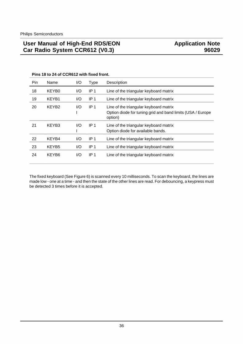
Pins 18 to 24 of CCR612 with fixed front.
Pin Name I/O Type Description
18 KEYB0 I/O IP 1 Line of the triangular keyboard matrix
19 KEYB1 I/O IP 1 Line of the triangular keyboard matrix
20 KEYB2 I/OI
IP 1 Line of the triangular keyboard matrixOption diode for tuning grid and band limits (USA / Europeoption)
21 KEYB3 I/OI
IP 1 Line of the triangular keyboard matrixOption diode for available bands.
22 KEYB4 I/O IP 1 Line of the triangular keyboard matrix
23 KEYB5 I/O IP 1 Line of the triangular keyboard matrix
24 KEYB6 I/O IP 1 Line of the triangular keyboard matrix
The fixed keyboard (See Figure 6) is scanned every 10 milliseconds. To scan the keyboard, the lines aremade low - one at a time - and then the state of the other lines are read. For debouncing, a keypress mustbe detected 3 times before it is accepted.
36
Philips Semiconductors
User Manual of High-End RDS/EONCar Radio System CCR612 (V0.3)
Application Note96029
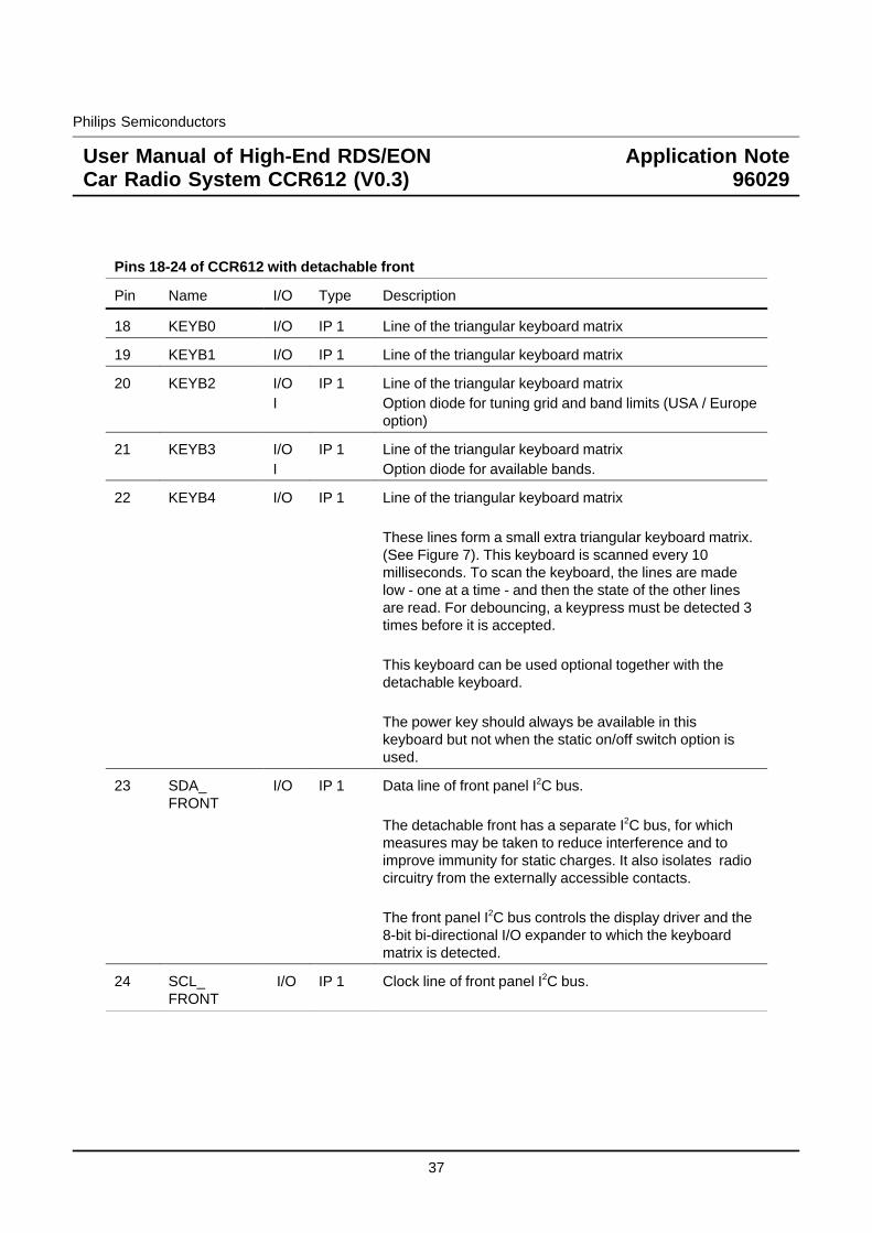
Pins 18-24 of CCR612 with detachable front
Pin Name I/O Type Description
18 KEYB0 I/O IP 1 Line of the triangular keyboard matrix
19 KEYB1 I/O IP 1 Line of the triangular keyboard matrix
20 KEYB2 I/OI
IP 1 Line of the triangular keyboard matrixOption diode for tuning grid and band limits (USA / Europeoption)
21 KEYB3 I/OI
IP 1 Line of the triangular keyboard matrixOption diode for available bands.
22 KEYB4 I/O IP 1 Line of the triangular keyboard matrix
These lines form a small extra triangular keyboard matrix.(See Figure 7). This keyboard is scanned every 10milliseconds. To scan the keyboard, the lines are madelow - one at a time - and then the state of the other linesare read. For debouncing, a keypress must be detected 3times before it is accepted.
This keyboard can be used optional together with thedetachable keyboard.
The power key should always be available in thiskeyboard but not when the static on/off switch option isused.
23 SDA_FRONT
I/O IP 1 Data line of front panel I2C bus.
The detachable front has a separate I2C bus, for whichmeasures may be taken to reduce interference and toimprove immunity for static charges. It also isolates radiocircuitry from the externally accessible contacts.
The front panel I2C bus controls the display driver and the8-bit bi-directional I/O expander to which the keyboardmatrix is detected.
24 SCL_FRONT
I/O IP 1 Clock line of front panel I2C bus.
37
Philips Semiconductors
User Manual of High-End RDS/EONCar Radio System CCR612 (V0.3)
Application Note96029
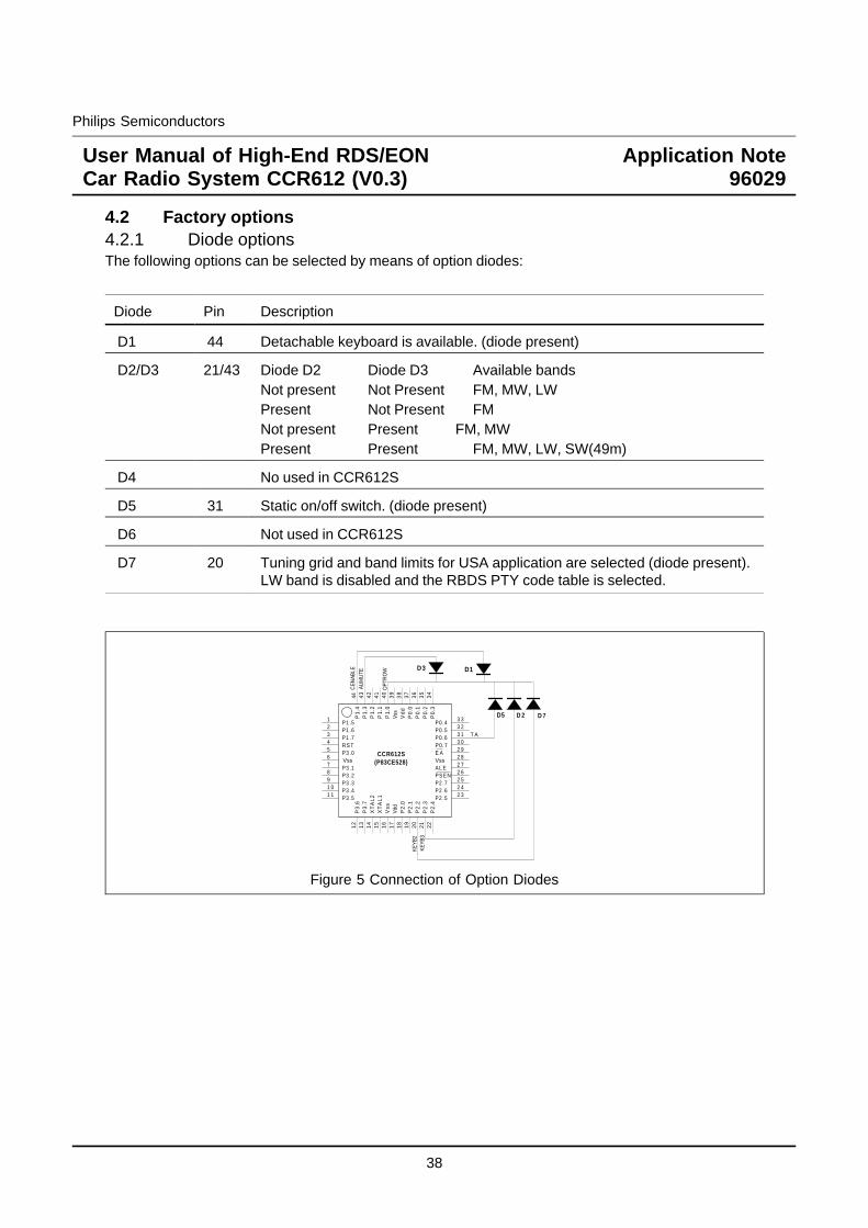
4.2 Factory options4.2.1 Diode optionsThe following options can be selected by means of option diodes:
Diode Pin Description
D1 44 Detachable keyboard is available. (diode present)
D2/D3 21/43 Diode D2 Diode D3 Available bandsNot present Not Present FM, MW, LWPresent Not Present FMNot present Present FM, MWPresent Present FM, MW, LW, SW(49m)
D4 No used in CCR612S
D5 31 Static on/off switch. (diode present)
D6 Not used in CCR612S
D7 20 Tuning grid and band limits for USA application are selected (diode present).LW band is disabled and the RBDS PTY code table is selected.
1234567891 01 1
12
14
13
15
16
17
18 19
20
21 22
2 3
2 52 4
2 62 72 82 93 03 13 23 3
34
35
36
37
38
39
40
41
42
43
44
P1 .5P1 .6
RS T
P3 .1P3 .2P3 .3P3 .4P3 .5
P3
.6P
3.7
XT
AL
2X
TA
L1
P2
.0P
2.1
P2
.2P
2.3
P2
.4
P2 .5P2 .6P2 .7PSENAL E
E AP0.7P0 .6P0 .5P0 .4
P0
.3P
0.2
P0
.1P
0.0
Vd
d
P1.
0P
1.1
P1
.2P
1.3
P1
.4
P1 .7
Vss
CCR612S(P83CE528)
P3 .0Vss
Vss
Vss
Vdd
D 2
CEN
ABLE
D5
T A
D1D3
AUM
UTE
OPT
RO
W
KEYB
2
D 7
KEYB
3
Figure 5 Connection of Option Diodes
38
Philips Semiconductors
User Manual of High-End RDS/EONCar Radio System CCR612 (V0.3)
Application Note96029
4.2.2 Automatically detected optionsCCR612S will detect the following options automatically:
Digital sound control chip.Presence / absence of a sound control chip (TEA632x) is detected by testing its I2C bus address.NOTE: The output pins AUMUTE, LOUDN and TA are always operational, even when a digital soundcontrol chip is installed. Cassette solenoid and AMS pause control functions are not available in caseno TEA632x is installed.
AMS DOLBY These functions are not available if the correspondingMTL output pin is connected to Vdd except for pins CAMSLOUDNESS and LOUD which must be connected to ground.DIAGNOSTICS
Presence of the CD-changer (check during power-on)
4.3 I2C bus addressesCCR612 I2C bus peripherals will be accessed at the following addresses:
C4 h PLL synthesizer TEA6811VC2 h IF system TEA6822T80 h Sound control circuit TEA632xA0 h NVM PCF8594
(The PCF8594 responds automatically to address A2 h for access to its upper half);40 h I/O expander PCF857470 h Display driver PCF8576
4.4 The keyboardTwo different configurations are possible:
1. A fixed keyboard, directly connected to the microcontroller.
2. A detachable keyboard, using an I/O expander to connect to the microcontroller via a dedicatedI2C bus. A fixed keyboard with a limited number of keys still remains possible.
39
Philips Semiconductors
User Manual of High-End RDS/EONCar Radio System CCR612 (V0.3)
Application Note96029
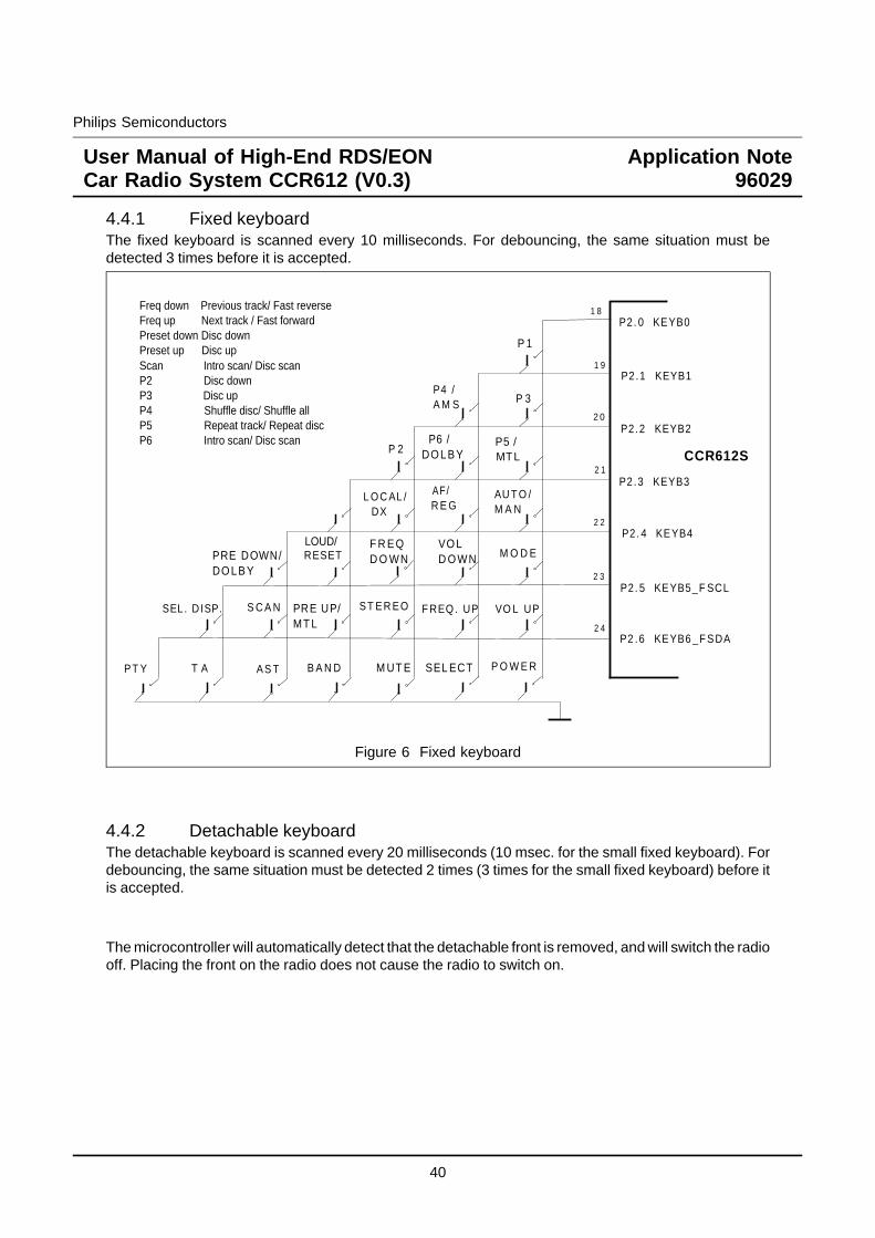
4.4.1 Fixed keyboardThe fixed keyboard is scanned every 10 milliseconds. For debouncing, the same situation must bedetected 3 times before it is accepted.
P 1
P 3P4 /A M S
P 2 P6 /DO LB Y
P5 / MTL
AU T O /M A N
L O C AL / DX
M O D EVO LD O WN
F R E QD O WNPRE DOWN/
DO LB Y
VO L UPF REQ . UPST ER EOPRE UP/MT L
SEL. DISP.
P O W E RSEL ECTM UT EB A N DAS TT APT Y
CCR612S
P2.1 KEYB1
P2.2 KEYB2
P2.3 KEYB3
P2. 4 KEYB4
P2. 5 KEYB5_F SCL
P2 .6 KEYB6 _F SDA
P2. 0 KEYB01 8
1 9
2 0
2 1
2 3
2 2
2 4
LOUD/RESET
AF/R E G
S C A N
Freq down Previous track/ Fast reverseFreq up Next track / Fast forwardPreset down Disc downPreset up Disc upScan Intro scan/ Disc scanP2 Disc downP3 Disc upP4 Shuffle disc/ Shuffle allP5 Repeat track/ Repeat discP6 Intro scan/ Disc scan
Figure 6 Fixed keyboard
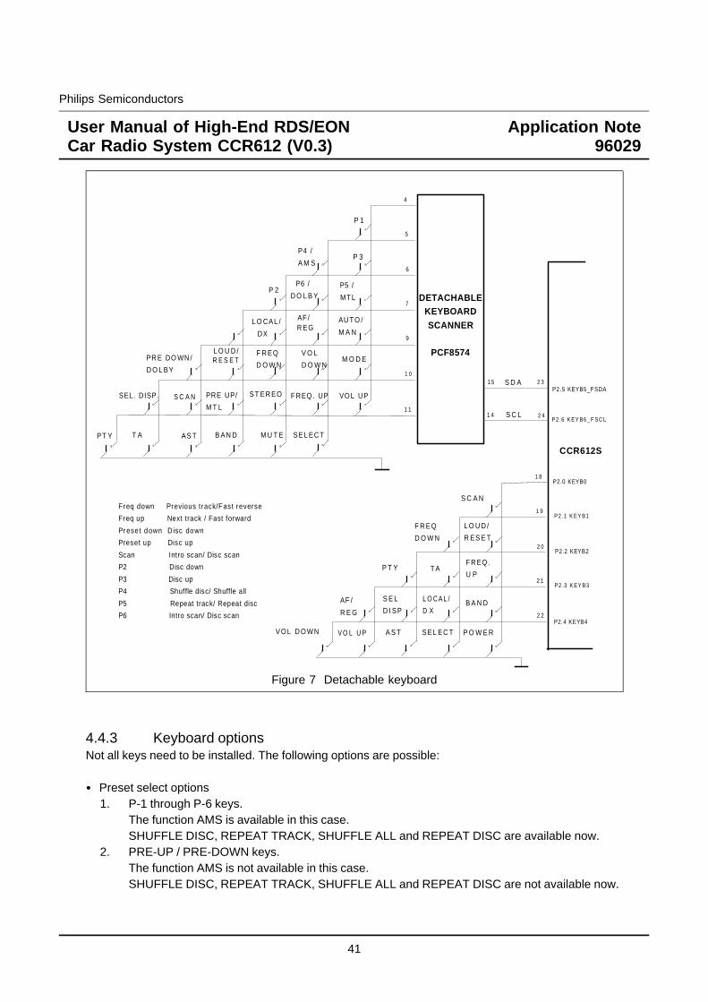
4.4.2 Detachable keyboardThe detachable keyboard is scanned every 20 milliseconds (10 msec. for the small fixed keyboard). Fordebouncing, the same situation must be detected 2 times (3 times for the small fixed keyboard) before itis accepted.
The microcontroller will automatically detect that the detachable front is removed, and will switch the radiooff. Placing the front on the radio does not cause the radio to switch on.
40
Philips Semiconductors
User Manual of High-End RDS/EONCar Radio System CCR612 (V0.3)
Application Note96029
CCR612S
2 3
2 41 4
1 5 S D A
S C L
4
5
6
7
1 1
DETACHABLEKEYBOARDSCANNER
PCF8574
9
1 0
P 1
P 3P4 /
A M S
P 2 P6 /
D O L B Y P5 /
MT L
AU T O /
M A NL O CAL /
DX
M O D EV O L
D O W N
F R EQ
D O W NPR E DO WN /
D O L BY
VO L UPF REQ . UPST ER EOPRE UP/
M T L
SEL. DISP.
SEL EC TM U T EB AN DAS TT APT Y
L O U D /R E S E T
AF /R EG
S C A N
P2.0 KEYB0
P2 .1 K EY B1
P2.2 KEYB2
P2 .3 K EY B3
P2 .6 K EY B6 _F SC L
P2.5 KEYB5_F SDA
1 8
1 9
2 0
2 1
2 2
S C A N
L O U D /
R ES E T
F R EQ
D O W N
P T Y T AF R EQ .
U P
B A N DS E L
D I SP
P O W E RSEL EC TA S TVO L D O WN V O L U P
L O C A L /
D XAF /
R E GP2.4 KEYB4
Freq down Previous track/Fast reverse
Freq up Next track / Fast forward
Pr ese t down D isc down
Preset up Disc up
Scan Intro scan/ Disc scan
P2 Disc down
P3 Disc up
P4 Shuffle disc/ Shuffle all
P5 Repeat track/ Repeat disc
P6 Intro scan/ Disc scan
Figure 7 Detachable keyboard
4.4.3 Keyboard optionsNot all keys need to be installed. The following options are possible:
Preset select options1. P-1 through P-6 keys.
The function AMS is available in this case.SHUFFLE DISC, REPEAT TRACK, SHUFFLE ALL and REPEAT DISC are available now.
2. PRE-UP / PRE-DOWN keys.The function AMS is not available in this case.SHUFFLE DISC, REPEAT TRACK, SHUFFLE ALL and REPEAT DISC are not available now.
41
Philips Semiconductors
User Manual of High-End RDS/EONCar Radio System CCR612 (V0.3)
Application Note96029
No digital sound control chip installed.In this case, the keys VOL-UP, VOL-DOWN are not required.
The following keys are optional. If omitted, the related functionality is not available, but other functionsare not affected.
- AUTO/MANUAL (Function also available by pressing FREQ-UP and FREQ-DOWN together)- LOUD (Loudness function also available in user programmable options; reset function
not available)- DISPLAY- PTY- MUTE- MODE- SCAN- LOCAL/DX
By means of an option diode, a selection can be made for a momentary power key (connected to portKEYB0 and ground) or a static on/off key (connected between port IGN and ground).
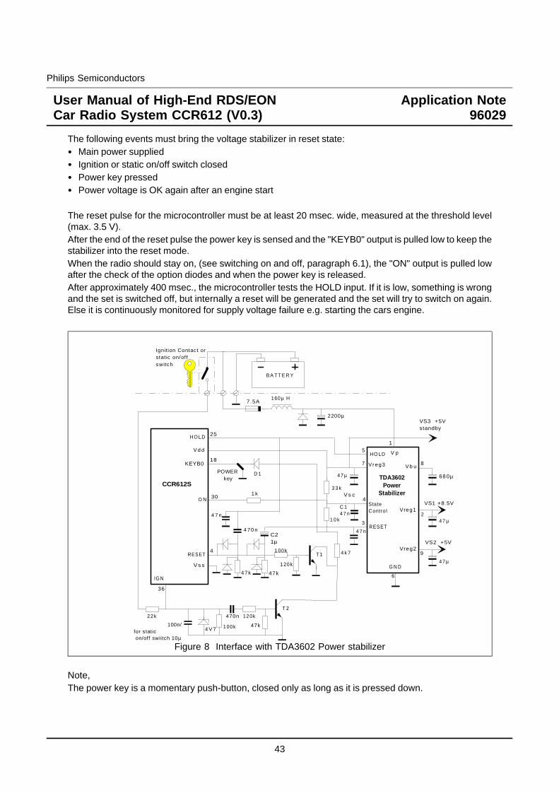
4.5 Power stabilizer interface.For switching the radio on and off, the microcontroller is linked with the voltage stabilizer circuit TDA3602.The pins involved in this interface are RESET, ON and HOLD.
Figure 8 shows a circuit diagram of the reset circuitry and the voltage stabilizer interface.
The TDA3602 has a number of different states, which are selected by the voltage on the state control inputVsc on pin 4. The following states are used:
State Vsc Description
OFF - No power
COMA > 3.6 V State when radio is off. Microcontroller supply isin low current mode; other supply voltages areoff.
RESET 1.2V < Vsc < 2.0V State during reset. Microcontroller supply is inhigh current mode; other supply voltages are stilloff.
ON < 1.2 V State when radio is on. All supply voltages are on.
To switch the radio on, the voltage stabilizer must be brought in reset state. It generates a reset pulse forthe microcontroller with its reset output pin. The microcontroller program starts, and decides whether theradio must stay on or must switch off again. When it must stay on, output pin "ON" is pulled low, bringingthe TDA3602 in the "ON" state. Else, the stabilizer stays in reset state, or returns to coma state eventually.
42
Philips Semiconductors
User Manual of High-End RDS/EONCar Radio System CCR612 (V0.3)
Application Note96029
The following events must bring the voltage stabilizer in reset state:Main power suppliedIgnition or static on/off switch closedPower key pressedPower voltage is OK again after an engine start
The reset pulse for the microcontroller must be at least 20 msec. wide, measured at the threshold level(max. 3.5 V).After the end of the reset pulse the power key is sensed and the "KEYB0" output is pulled low to keep thestabilizer into the reset mode.When the radio should stay on, (see switching on and off, paragraph 6.1), the "ON" output is pulled lowafter the check of the option diodes and when the power key is released.After approximately 400 msec., the microcontroller tests the HOLD input. If it is low, something is wrongand the set is switched off, but internally a reset will be generated and the set will try to switch on again.Else it is continuously monitored for supply voltage failure e.g. starting the cars engine.
KEYB0
CCR612S
HO LD
V d d
25
18HO LD
Vr eg3
RES ET
O N
RES ET
IG N
V s s
TDA3602Power
Stabilizer
StateContro l
G N D
Vreg2
Vreg1
V b u
V p
VS1 +8.5V
VS2 +5V
1
4
7
5
8
2
9
3
6
36
4
30
B A T T E R Y
Ignition Contac t orstat ic on/of fswitch
VS3 +5Vstandby
POWER key
3 3 k
4 7 µ 68 0µ
4 7 µ
4 7 µ
7.5A160 µ H
2200µ
1 00 k
1 00 k
1 20 k
12 0k
47k4 V 7
100n/for static on/off swiitch 10µ
470n
1 0 k
T 1
T 2
2 2 k
D 1
V s c
C 14 7 n
C21µ
4 7 n
1 k
4 70 n
47k47k
4 7 n
4 k 7
Figure 8 Interface with TDA3602 Power stabilizer
Note,The power key is a momentary push-button, closed only as long as it is pressed down.
43
Philips Semiconductors
User Manual of High-End RDS/EONCar Radio System CCR612 (V0.3)
Application Note96029
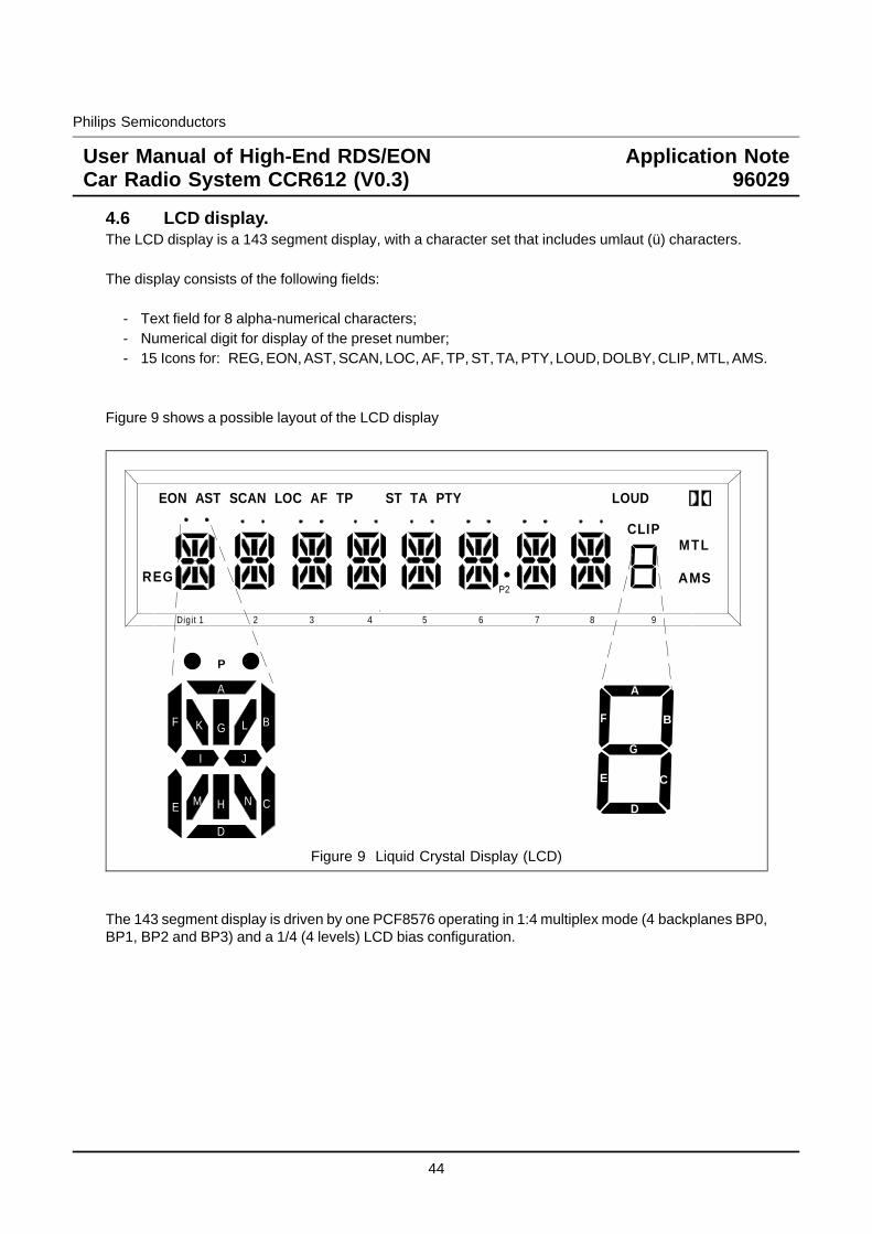
4.6 LCD display.The LCD display is a 143 segment display, with a character set that includes umlaut (ü) characters.
The display consists of the following fields:
- Text field for 8 alpha-numerical characters;- Numerical digit for display of the preset number;- 15 Icons for: REG, EON, AST, SCAN, LOC, AF, TP, ST, TA, PTY, LOUD, DOLBY, CLIP, MTL, AMS.
Figure 9 shows a possible layout of the LCD display
A
B
C
D
E
F
G
1 2 3 4 5 6 7 8 9
P
AMS
Digit
REG
EON AST SCAN LOC AF TP ST TA PTY LOUD
MTLCLIP
P2
A
B
C
D
E
F G
H
I J
K L
M N
Figure 9 Liquid Crystal Display (LCD)
The 143 segment display is driven by one PCF8576 operating in 1:4 multiplex mode (4 backplanes BP0,BP1, BP2 and BP3) and a 1/4 (4 levels) LCD bias configuration.
44
Philips Semiconductors
User Manual of High-End RDS/EONCar Radio System CCR612 (V0.3)
Application Note96029
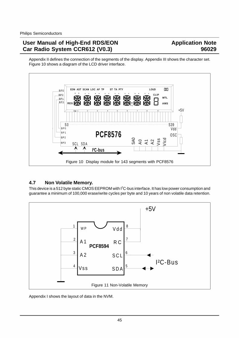
Appendix II defines the connection of the segments of the display. Appendix III shows the character set.Figure 10 shows a diagram of the LCD driver interface.
PCF8576S 0 S39
B P 0
BP3
B P 1
SC L
I²C-bus
Vd dO S C
+5V
S D A A0
A1
A2
Vss
Vlc
dBP2
SA0
1 2 3 4 5 6 7 8 9
AMS
Digit
REG
EON AST SCAN LOC AF TP ST TA PTY LOUD
MTLCLIP
P 2
B P 0
BP2
BP1B P 3
Figure 10 Display module for 143 segments with PCF8576
4.7 Non Volatile Memory.This device is a 512 byte static CMOS EEPROM with I2C-bus interface. It has low power consumption andguarantee a minimum of 100,000 erase/write cycles per byte and 10 years of non volatile data retention.
W P
A 1
A 2
Vss
V d d
R C
S C L
S D A
+5V
I²C-Bus
1
2
3
4 5
6
7
8
PCF8594
Figure 11 Non-Volatile Memory
Appendix I shows the layout of data in the NVM.
45
Philips Semiconductors
User Manual of High-End RDS/EONCar Radio System CCR612 (V0.3)
Application Note96029
5 KEY FUNCTIONSIn the following table External mode is: CD-changer mode, Cassette mode or External plug mode.
Key Description
POWER When the radio is off, this key generates a reset pulse to start themicrocontroller. The voltage stabilizer is switched on, but the radio will startplaying only after the key is released.
Pressed while the radio was on, the radio is switched off. It saves allinformation about its current setting, and restores the information whenswitched on again.
BAND Step cyclically through the tuning bands (not accessible in Cassette & Externalmode) in the order:
FM-1 -> FM-2 -> MW -> LW -> SW -> FM-1 -> ...FM-AST -> FM-1 -> ...MW-AST -> MW -> ...
Depending on the installed band option diodes, the LW, MW and or SW bandsmay be skipped. Depending on the option concerning the band limits andtuning grid the LW band will be disabled (option set to USA).
When a new band is selected, the radio is tuned to the preset or frequency thatwas last used in that band.
In option programming mode, this key toggles the current option:
2 SPKRS <-> 4 SPKRSLOUD OFF <-> LOUD ONTA LVL -2 <-> -1..0..+1..+2
46
Philips Semiconductors
User Manual of High-End RDS/EONCar Radio System CCR612 (V0.3)
Application Note96029
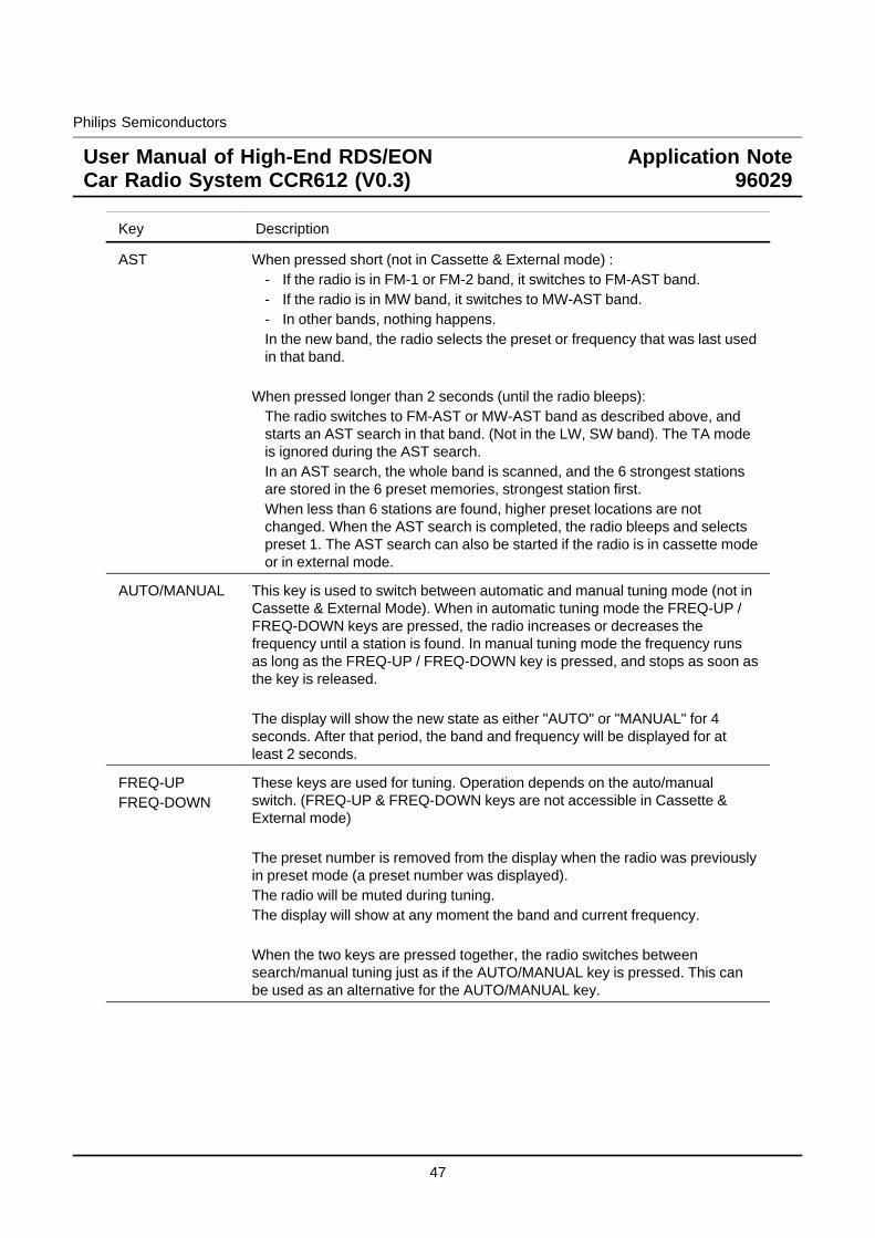
Key Description
AST When pressed short (not in Cassette & External mode) :- If the radio is in FM-1 or FM-2 band, it switches to FM-AST band.- If the radio is in MW band, it switches to MW-AST band.- In other bands, nothing happens.In the new band, the radio selects the preset or frequency that was last usedin that band.
When pressed longer than 2 seconds (until the radio bleeps):The radio switches to FM-AST or MW-AST band as described above, andstarts an AST search in that band. (Not in the LW, SW band). The TA modeis ignored during the AST search.In an AST search, the whole band is scanned, and the 6 strongest stationsare stored in the 6 preset memories, strongest station first.When less than 6 stations are found, higher preset locations are notchanged. When the AST search is completed, the radio bleeps and selectspreset 1. The AST search can also be started if the radio is in cassette modeor in external mode.
AUTO/MANUAL This key is used to switch between automatic and manual tuning mode (not inCassette & External Mode). When in automatic tuning mode the FREQ-UP /FREQ-DOWN keys are pressed, the radio increases or decreases thefrequency until a station is found. In manual tuning mode the frequency runsas long as the FREQ-UP / FREQ-DOWN key is pressed, and stops as soon asthe key is released.
The display will show the new state as either "AUTO" or "MANUAL" for 4seconds. After that period, the band and frequency will be displayed for atleast 2 seconds.
FREQ-UPFREQ-DOWN
These keys are used for tuning. Operation depends on the auto/manualswitch. (FREQ-UP & FREQ-DOWN keys are not accessible in Cassette &External mode)
The preset number is removed from the display when the radio was previouslyin preset mode (a preset number was displayed).The radio will be muted during tuning.The display will show at any moment the band and current frequency.
When the two keys are pressed together, the radio switches betweensearch/manual tuning just as if the AUTO/MANUAL key is pressed. This canbe used as an alternative for the AUTO/MANUAL key.
47
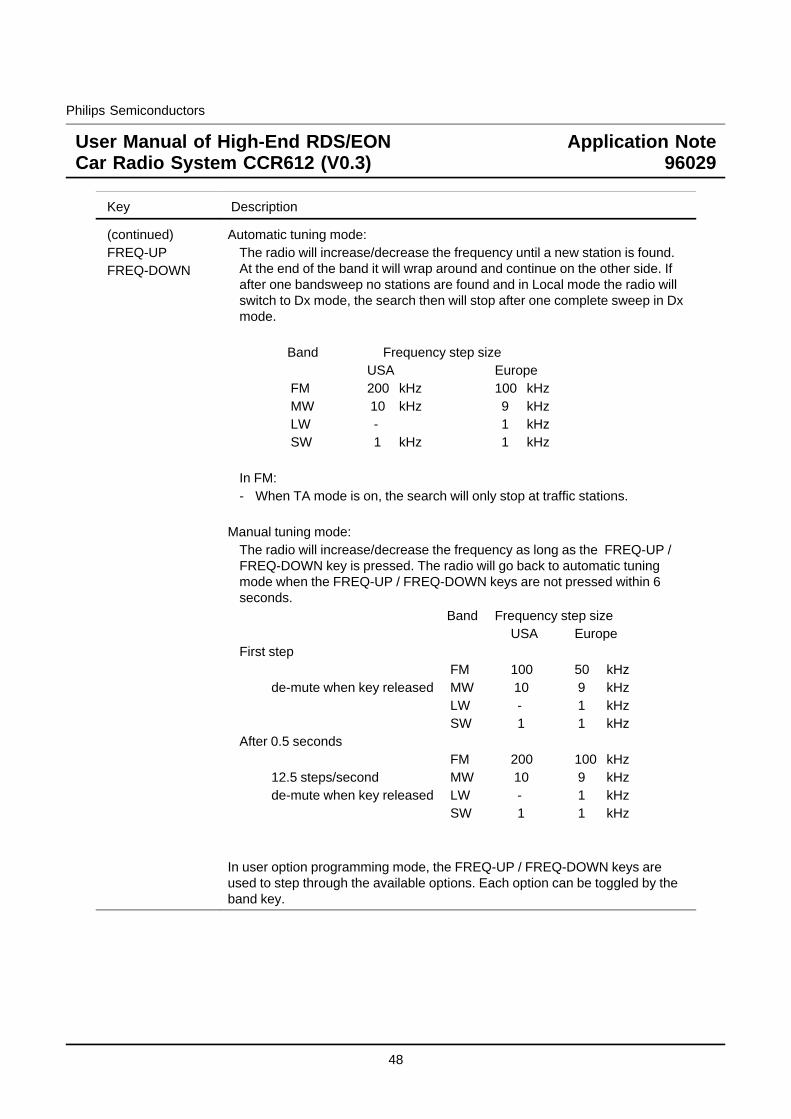
Philips Semiconductors
User Manual of High-End RDS/EONCar Radio System CCR612 (V0.3)
Application Note96029
Key Description
(continued)FREQ-UPFREQ-DOWN
Automatic tuning mode:The radio will increase/decrease the frequency until a new station is found.At the end of the band it will wrap around and continue on the other side. Ifafter one bandsweep no stations are found and in Local mode the radio willswitch to Dx mode, the search then will stop after one complete sweep in Dxmode.
Band Frequency step sizeUSA Europe
FM 200 kHz 100 kHzMW 10 kHz 9 kHzLW - 1 kHzSW 1 kHz 1 kHz
In FM:- When TA mode is on, the search will only stop at traffic stations.
Manual tuning mode:The radio will increase/decrease the frequency as long as the FREQ-UP /FREQ-DOWN key is pressed. The radio will go back to automatic tuningmode when the FREQ-UP / FREQ-DOWN keys are not pressed within 6seconds.
Band Frequency step sizeUSA Europe
First stepFM 100 50 kHz
de-mute when key released MW 10 9 kHzLW - 1 kHzSW 1 1 kHz
After 0.5 secondsFM 200 100 kHz
12.5 steps/second MW 10 9 kHzde-mute when key released LW - 1 kHz
SW 1 1 kHz
In user option programming mode, the FREQ-UP / FREQ-DOWN keys areused to step through the available options. Each option can be toggled by theband key.
48
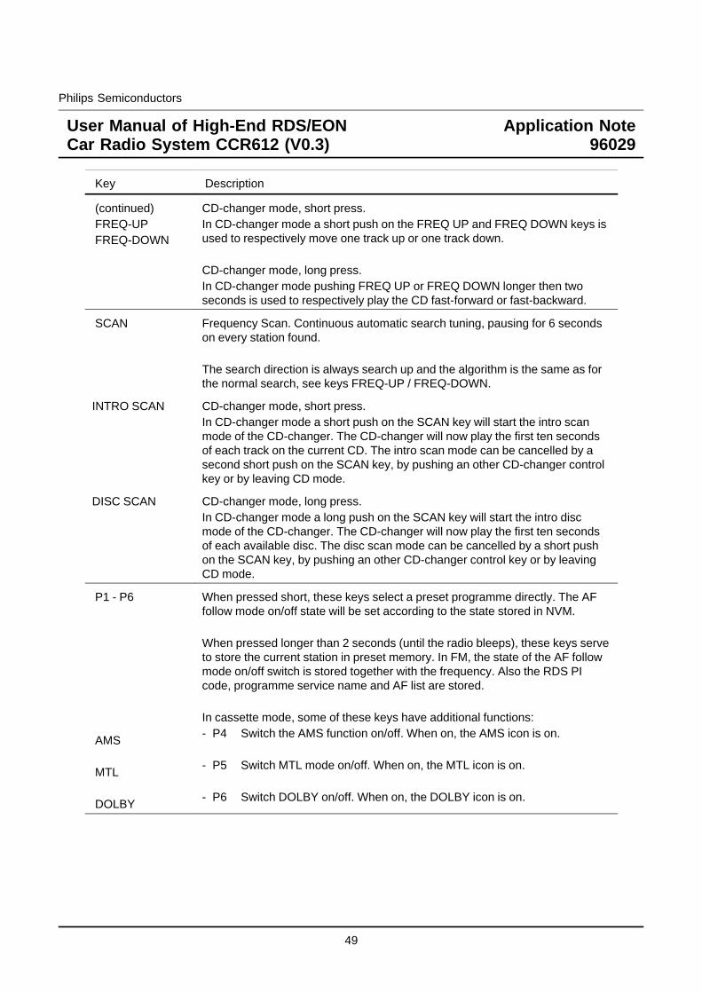
Philips Semiconductors
User Manual of High-End RDS/EONCar Radio System CCR612 (V0.3)
Application Note96029
Key Description
(continued)FREQ-UPFREQ-DOWN
CD-changer mode, short press.In CD-changer mode a short push on the FREQ UP and FREQ DOWN keys isused to respectively move one track up or one track down.
CD-changer mode, long press.In CD-changer mode pushing FREQ UP or FREQ DOWN longer then twoseconds is used to respectively play the CD fast-forward or fast-backward.
SCAN Frequency Scan. Continuous automatic search tuning, pausing for 6 secondson every station found.
The search direction is always search up and the algorithm is the same as forthe normal search, see keys FREQ-UP / FREQ-DOWN.
INTRO SCAN CD-changer mode, short press.In CD-changer mode a short push on the SCAN key will start the intro scanmode of the CD-changer. The CD-changer will now play the first ten secondsof each track on the current CD. The intro scan mode can be cancelled by asecond short push on the SCAN key, by pushing an other CD-changer controlkey or by leaving CD mode.
DISC SCAN CD-changer mode, long press.In CD-changer mode a long push on the SCAN key will start the intro discmode of the CD-changer. The CD-changer will now play the first ten secondsof each available disc. The disc scan mode can be cancelled by a short pushon the SCAN key, by pushing an other CD-changer control key or by leavingCD mode.
P1 - P6
AMS
MTL
DOLBY
When pressed short, these keys select a preset programme directly. The AFfollow mode on/off state will be set according to the state stored in NVM.
When pressed longer than 2 seconds (until the radio bleeps), these keys serveto store the current station in preset memory. In FM, the state of the AF followmode on/off switch is stored together with the frequency. Also the RDS PIcode, programme service name and AF list are stored.
In cassette mode, some of these keys have additional functions:- P4 Switch the AMS function on/off. When on, the AMS icon is on.
- P5 Switch MTL mode on/off. When on, the MTL icon is on.
- P6 Switch DOLBY on/off. When on, the DOLBY icon is on.
49
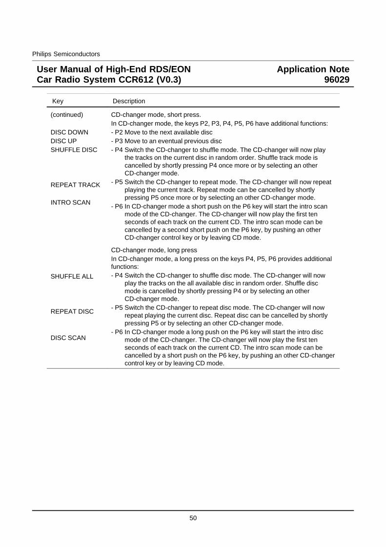
Philips Semiconductors
User Manual of High-End RDS/EONCar Radio System CCR612 (V0.3)
Application Note96029
Key Description
(continued)
DISC DOWNDISC UPSHUFFLE DISC
REPEAT TRACK
INTRO SCAN
CD-changer mode, short press.In CD-changer mode, the keys P2, P3, P4, P5, P6 have additional functions:- P2 Move to the next available disc- P3 Move to an eventual previous disc- P4 Switch the CD-changer to shuffle mode. The CD-changer will now play
the tracks on the current disc in random order. Shuffle track mode iscancelled by shortly pressing P4 once more or by selecting an otherCD-changer mode.
- P5 Switch the CD-changer to repeat mode. The CD-changer will now repeatplaying the current track. Repeat mode can be cancelled by shortlypressing P5 once more or by selecting an other CD-changer mode.
- P6 In CD-changer mode a short push on the P6 key will start the intro scanmode of the CD-changer. The CD-changer will now play the first tenseconds of each track on the current CD. The intro scan mode can becancelled by a second short push on the P6 key, by pushing an otherCD-changer control key or by leaving CD mode.
SHUFFLE ALL
REPEAT DISC
DISC SCAN
CD-changer mode, long pressIn CD-changer mode, a long press on the keys P4, P5, P6 provides additionalfunctions:- P4 Switch the CD-changer to shuffle disc mode. The CD-changer will now
play the tracks on the all available disc in random order. Shuffle discmode is cancelled by shortly pressing P4 or by selecting an otherCD-changer mode.
- P5 Switch the CD-changer to repeat disc mode. The CD-changer will nowrepeat playing the current disc. Repeat disc can be cancelled by shortlypressing P5 or by selecting an other CD-changer mode.
- P6 In CD-changer mode a long push on the P6 key will start the intro discmode of the CD-changer. The CD-changer will now play the first tenseconds of each track on the current CD. The intro scan mode can becancelled by a short push on the P6 key, by pushing an other CD-changercontrol key or by leaving CD mode.
50
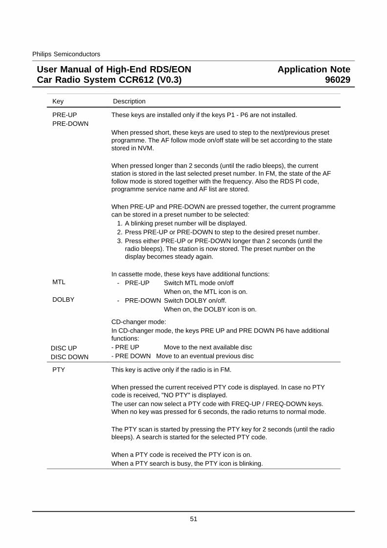
Philips Semiconductors
User Manual of High-End RDS/EONCar Radio System CCR612 (V0.3)
Application Note96029
Key Description
PRE-UPPRE-DOWN
MTL
DOLBY
These keys are installed only if the keys P1 - P6 are not installed.
When pressed short, these keys are used to step to the next/previous presetprogramme. The AF follow mode on/off state will be set according to the statestored in NVM.
When pressed longer than 2 seconds (until the radio bleeps), the currentstation is stored in the last selected preset number. In FM, the state of the AFfollow mode is stored together with the frequency. Also the RDS PI code,programme service name and AF list are stored.
When PRE-UP and PRE-DOWN are pressed together, the current programmecan be stored in a preset number to be selected:
1. A blinking preset number will be displayed.2. Press PRE-UP or PRE-DOWN to step to the desired preset number.3. Press either PRE-UP or PRE-DOWN longer than 2 seconds (until the
radio bleeps). The station is now stored. The preset number on thedisplay becomes steady again.
In cassette mode, these keys have additional functions:- PRE-UP Switch MTL mode on/off
When on, the MTL icon is on.- PRE-DOWN Switch DOLBY on/off.
When on, the DOLBY icon is on.
DISC UPDISC DOWN
CD-changer mode:In CD-changer mode, the keys PRE UP and PRE DOWN P6 have additionalfunctions:- PRE UP Move to the next available disc- PRE DOWN Move to an eventual previous disc
PTY This key is active only if the radio is in FM.
When pressed the current received PTY code is displayed. In case no PTYcode is received, "NO PTY" is displayed.The user can now select a PTY code with FREQ-UP / FREQ-DOWN keys.When no key was pressed for 6 seconds, the radio returns to normal mode.
The PTY scan is started by pressing the PTY key for 2 seconds (until the radiobleeps). A search is started for the selected PTY code.
When a PTY code is received the PTY icon is on.When a PTY search is busy, the PTY icon is blinking.
51
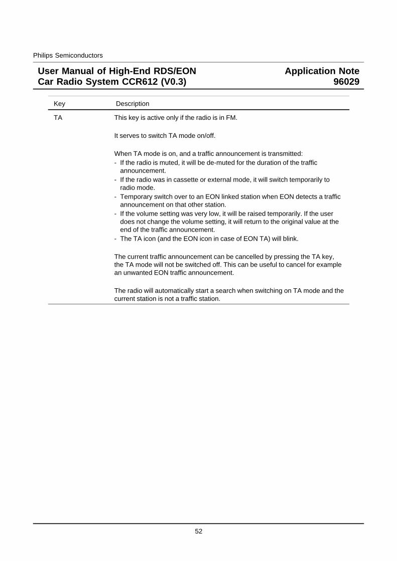
Philips Semiconductors
User Manual of High-End RDS/EONCar Radio System CCR612 (V0.3)
Application Note96029
Key Description
TA This key is active only if the radio is in FM.
It serves to switch TA mode on/off.
When TA mode is on, and a traffic announcement is transmitted:- If the radio is muted, it will be de-muted for the duration of the traffic
announcement.- If the radio was in cassette or external mode, it will switch temporarily to
radio mode.- Temporary switch over to an EON linked station when EON detects a traffic
announcement on that other station.- If the volume setting was very low, it will be raised temporarily. If the user
does not change the volume setting, it will return to the original value at theend of the traffic announcement.
- The TA icon (and the EON icon in case of EON TA) will blink.
The current traffic announcement can be cancelled by pressing the TA key,the TA mode will not be switched off. This can be useful to cancel for examplean unwanted EON traffic announcement.
The radio will automatically start a search when switching on TA mode and thecurrent station is not a traffic station.
52

Philips Semiconductors
User Manual of High-End RDS/EONCar Radio System CCR612 (V0.3)
Application Note96029
Key Description
AF
REGIONAL
When pressed short:Switches AF follow mode on/off.
The state of the AF follow mode is displayed by the AF Icon:Icon off: AF follow mode offIcon on: AF follow mode on; RDS reception OK.Icon blinking: AF follow mode selected, but no RDS data
received.
When AF follow mode is on, the radio will from time to time measure thesignal strength of the alternative frequencies that come with the RDS data.The interval between measurements depends on the signal strength of thecurrent station, in the order of 1 minute for strong stations to a few secondsfor weak stations. When the radio finds an alternative frequency that is - inseveral successive measurements - stronger than the current frequency, itswitches over to that frequency.
When pressed longer than 2 seconds (until the radio bleeps):Toggles the regional on/off status displayed via an icon.
To check whether an alternative frequency is a real alternative for thecurrent station, the radio compares PI codes.
- Regional mode is on:The PI codes must be exactly identical or a SUPRA regional variant.
- Regional mode is off:The region identification code in the PI code is ignored.
When regional mode is off, the radio may switch to any programme servicecarrying a PI code equal to the current PI code. In this case the regionalidentification is not taken into account. When regional mode is on, the radiowill only switch to a programme service carrying exactly the sameprogramme. In both cases the radio may switch to transmitters broadcastingin Supra-regional mode. For USA application (RBDS) the regional functionwill only work for PI codes above B000hex. PI codes below B000hex do nothave regional variants. AF switching is only allowed to stations with exactlythe same PI code.
53
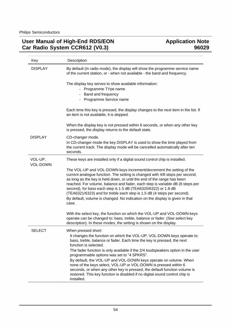
Philips Semiconductors
User Manual of High-End RDS/EONCar Radio System CCR612 (V0.3)
Application Note96029
Key Description
DISPLAY By default (in radio mode), the display will show the programme service nameof the current station, or - when not available - the band and frequency.
The display key serves to show available information:- Programme TYpe name- Band and frequency- Programme Service name
Each time this key is pressed, the display changes to the next item in the list. Ifan item is not available, it is skipped.
When the display key is not pressed within 6 seconds, or when any other keyis pressed, the display returns to the default state.
DISPLAY CD-changer mode.In CD-changer mode the key DISPLAY is used to show the time played fromthe current track. The display mode will be cancelled automatically after tenseconds.
VOL-UP,VOL-DOWN
These keys are installed only if a digital sound control chip is installed.
The VOL-UP and VOL-DOWN keys increment/decrement the setting of thecurrent analogue function. The setting is changed with 4/8 steps per second,as long as the key is held down, or until the end of the range has beenreached. For volume, balance and fader, each step is variable dB (8 steps persecond), for bass each step is 1.5 dB (TEA6320/6322) or 1.8 dB(TEA6321/6323) and for treble each step is 1.5 dB (4 steps per second).By default, volume is changed. No indication on the display is given in thatcase.
With the select key, the function on which the VOL-UP and VOL-DOWN keysoperate can be changed to: bass, treble, balance or fader. (See select keydescription). In these modes, the setting is shown on the display.
SELECT When pressed short:It changes the function on which the VOL-UP, VOL-DOWN keys operate to:bass, treble, balance or fader. Each time the key is pressed, the nextfunction is selected.The fader function is only available if the 2/4 loudspeakers option in the userprogrammable options was set to "4 SPKRS".By default, the VOL-UP and VOL-DOWN keys operate on volume. Whennone of the keys select, VOL-UP or VOL-DOWN is pressed within 6seconds, or when any other key is pressed, the default function volume isrestored. This key function is disabled if no digital sound control chip isinstalled.
54
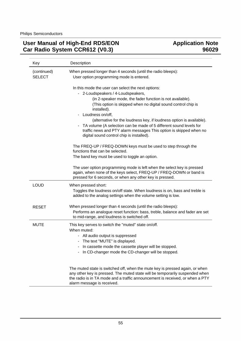
Philips Semiconductors
User Manual of High-End RDS/EONCar Radio System CCR612 (V0.3)
Application Note96029
Key Description
(continued)SELECT
When pressed longer than 4 seconds (until the radio bleeps):User option programming mode is entered.
In this mode the user can select the next options:- 2-Loudspeakers / 4-Loudspeakers,
(in 2-speaker mode, the fader function is not available).(This option is skipped when no digital sound control chip isinstalled).
- Loudness on/off,(alternative for the loudness key, if loudness option is available).
- TA volume (A selection can be made of 5 different sound levels fortraffic news and PTY alarm messages This option is skipped when nodigital sound control chip is installed).
The FREQ-UP / FREQ-DOWN keys must be used to step through thefunctions that can be selected.The band key must be used to toggle an option.
The user option programming mode is left when the select key is pressedagain, when none of the keys select, FREQ-UP / FREQ-DOWN or band ispressed for 6 seconds, or when any other key is pressed.
LOUD
RESET
When pressed short:Toggles the loudness on/off state. When loudness is on, bass and treble isadded to the analog settings when the volume setting is low.
When pressed longer than 4 seconds (until the radio bleeps):Performs an analogue reset function: bass, treble, balance and fader are setto mid-range, and loudness is switched off.
MUTE This key serves to switch the "muted" state on/off.When muted:
- All audio output is suppressed- The text "MUTE" is displayed.- In cassette mode the cassette player will be stopped.- In CD-changer mode the CD-changer will be stopped.
The muted state is switched off, when the mute key is pressed again, or whenany other key is pressed. The muted state will be temporarily suspended whenthe radio is in TA mode and a traffic announcement is received, or when a PTYalarm message is received.
55
Philips Semiconductors
User Manual of High-End RDS/EONCar Radio System CCR612 (V0.3)
Application Note96029
Key Description
STEREO This key is only active in FM. It is used to force mono reception if stereoreception has too much noise. The mono/stereo state is reset to stereo by alluser tuning operations or preset selections.
After pressing the key, the current state is displayed in the LCD text window bymeans of the text "STEREO" or "MONO" for 4 seconds. If - within that period -the key is pressed again, the state is toggled (only possible when a stereotransmitter is received), and the new state is displayed - again for 4 seconds.
The stereo icon on the display shows the state of the stereo decoder. The iconis on in case of stereo reception. The icon is off in case of mono reception or incase forced mono is selected.
LOCAL/DX This key can be used to control an attenuator in the FM antenna circuit duringsearch. Attenuation may be inserted to reduce intermodulation caused bystrong adjacent stations.By pressing the LOCAL/DX key, the current Local / Dx status is toggled. Thisstatus is displayed via an icon.
For FM, the Local / Dx switch is incorporated in the TEA6811. Putting the radioin Local mode results in an attenuation of the aerial signal with 15 dB. For AM,the signal levels read back from the TEA6822 are used to create the Local /Dxfunctionality. In AM mode, the search stop level for Local is set 22 dB higherthan when the radio is in Dx-mode.
MODE This key is used to overrule the default selection of the audio source: radio,CD-changer, cassette or external.
Each time the key is pressed, the next input source is selected in the order:radio -> CD-changer -> cassette -> external
with the restrictions:- CD-changer is selected only if the CD-changer was connected during
power-on.- Cassette is selected only if a tape is present in the cassette deck.- External is selected only if a connector is inserted in the external input
jack.
56
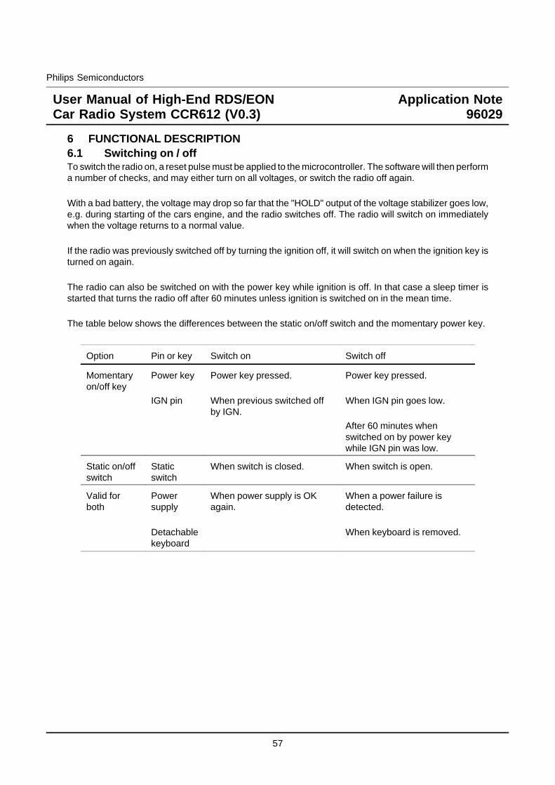
Philips Semiconductors
User Manual of High-End RDS/EONCar Radio System CCR612 (V0.3)
Application Note96029
6 FUNCTIONAL DESCRIPTION6.1 Switching on / offTo switch the radio on, a reset pulse must be applied to the microcontroller. The software will then performa number of checks, and may either turn on all voltages, or switch the radio off again.
With a bad battery, the voltage may drop so far that the "HOLD" output of the voltage stabilizer goes low,e.g. during starting of the cars engine, and the radio switches off. The radio will switch on immediatelywhen the voltage returns to a normal value.
If the radio was previously switched off by turning the ignition off, it will switch on when the ignition key isturned on again.
The radio can also be switched on with the power key while ignition is off. In that case a sleep timer isstarted that turns the radio off after 60 minutes unless ignition is switched on in the mean time.
The table below shows the differences between the static on/off switch and the momentary power key.
Option Pin or key Switch on Switch off
Momentaryon/off key
Power key
IGN pin
Power key pressed.
When previous switched offby IGN.
Power key pressed.
When IGN pin goes low.
After 60 minutes whenswitched on by power keywhile IGN pin was low.
Static on/offswitch
Staticswitch
When switch is closed. When switch is open.
Valid forboth
Powersupply
Detachablekeyboard
When power supply is OKagain.
When a power failure isdetected.
When keyboard is removed.
57
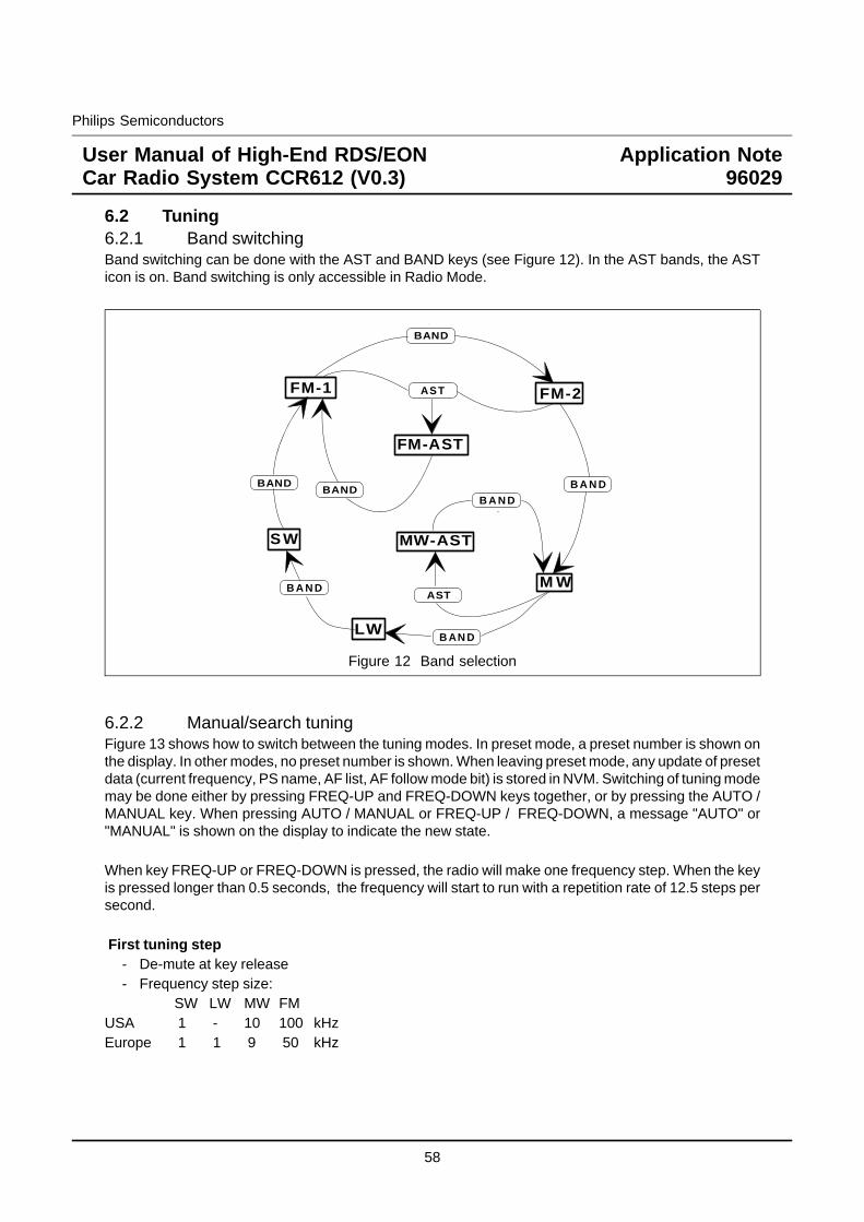
Philips Semiconductors
User Manual of High-End RDS/EONCar Radio System CCR612 (V0.3)
Application Note96029
6.2 Tuning6.2.1 Band switchingBand switching can be done with the AST and BAND keys (see Figure 12). In the AST bands, the ASTicon is on. Band switching is only accessible in Radio Mode.
BAND
ASTFM-1 FM-2
FM-AST
M W
MW-AST
LW
B A N D
B AN D
BAND
AST
BANDB A N D
B A N D
S W
Figure 12 Band selection
6.2.2 Manual/search tuningFigure 13 shows how to switch between the tuning modes. In preset mode, a preset number is shown onthe display. In other modes, no preset number is shown. When leaving preset mode, any update of presetdata (current frequency, PS name, AF list, AF follow mode bit) is stored in NVM. Switching of tuning modemay be done either by pressing FREQ-UP and FREQ-DOWN keys together, or by pressing the AUTO /MANUAL key. When pressing AUTO / MANUAL or FREQ-UP / FREQ-DOWN, a message "AUTO" or"MANUAL" is shown on the display to indicate the new state.
When key FREQ-UP or FREQ-DOWN is pressed, the radio will make one frequency step. When the keyis pressed longer than 0.5 seconds, the frequency will start to run with a repetition rate of 12.5 steps persecond.
First tuning step- De-mute at key release- Frequency step size:
SW LW MW FMUSA 1 - 10 100 kHzEurope 1 1 9 50 kHz
58
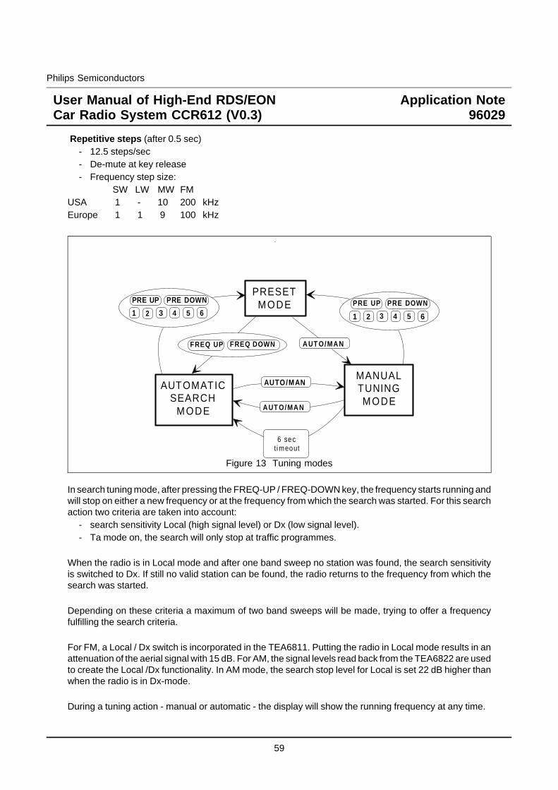
Philips Semiconductors
User Manual of High-End RDS/EONCar Radio System CCR612 (V0.3)
Application Note96029
Repetitive steps (after 0.5 sec)- 12.5 steps/sec- De-mute at key release- Frequency step size:
SW LW MW FMUSA 1 - 10 200 kHzEurope 1 1 9 100 kHz
PRE UP
FREQ DOWN A UT O/MA N
PRESETMODE
MANUALTUNINGMODE
AUTOMATICSEARCH
MODE
AUTO/MAN
A UT O/MA N
6 secti meout
PRE DOWN
1 2
FREQ UP
3 4 5 6PRE UP PRE DOWN
1 2 3 4 5 6
Figure 13 Tuning modes
In search tuning mode, after pressing the FREQ-UP / FREQ-DOWN key, the frequency starts running andwill stop on either a new frequency or at the frequency from which the search was started. For this searchaction two criteria are taken into account:
- search sensitivity Local (high signal level) or Dx (low signal level).- Ta mode on, the search will only stop at traffic programmes.
When the radio is in Local mode and after one band sweep no station was found, the search sensitivityis switched to Dx. If still no valid station can be found, the radio returns to the frequency from which thesearch was started.
Depending on these criteria a maximum of two band sweeps will be made, trying to offer a frequencyfulfilling the search criteria.
For FM, a Local / Dx switch is incorporated in the TEA6811. Putting the radio in Local mode results in anattenuation of the aerial signal with 15 dB. For AM, the signal levels read back from the TEA6822 are usedto create the Local /Dx functionality. In AM mode, the search stop level for Local is set 22 dB higher thanwhen the radio is in Dx-mode.
During a tuning action - manual or automatic - the display will show the running frequency at any time.
59
Philips Semiconductors
User Manual of High-End RDS/EONCar Radio System CCR612 (V0.3)
Application Note96029
6.2.3 Frequency scanThe frequency scan mode enables the user to listen to all stations transmitted in the selected band (FM,MW, LW or SW). The radio pauses for 6 seconds on every station found before search is started again.During frequency scan, TA mode is included in the stop criteria in the same way as during normal search.EON traffic announcements are skipped during frequency scan mode.Frequency scan is cancelled by every other tuning function. The radio will switch to the last valid stationwhen the cancelling takes place during search. Frequency scan mode is only accessible when the radiois in Radio Mode.
6.2.4 Selecting preset stationsIn each band, there are 6 presets. To select a preset station:
If the radio is equipped with 6 preset selection keys (P1 - P6)- Press short on the key of the desired station.
If the radio is equipped only with PRE-UP / PRE-DOWN keys- Press either PRE-UP or PRE-DOWN repeatedly until the desired station is selected.
(Do not hold down the key, because then the preset store function will be executed).If initially no preset number was displayed, the first preset selected will be the last preset numberused in the band.
Selecting preset stations is only accessible in Radio Mode.
6.2.5 Storing stations in preset memoryIf the radio is equipped with 6 preset selection keys (P1 - P6)
- Press key of the preset number to be stored until the radio bleeps (2 seconds).The station is now stored.
If the radio is equipped only with PRE-UP / PRE-DOWN keys- If the current preset number is the desired preset number:
- Press either the PRE-UP or PRE-DOWN key until the radio bleeps (2 seconds).The station is now stored.
- If the current preset number is not the desired preset number:- Press keys PRE-UP and PRE-DOWN at the same time.
The preset number will start to blink.- Press either PRE-UP or PRE-DOWN repeatedly until the desired preset number is displayed.
(The tuned frequency does not change).- Press either the PRE-UP or PRE-DOWN key until the radio bleeps (2 seconds).
The station is now stored. The preset number stops blinking.
The preset store mode is cancelled when the PRE-UP and PRE-DOWN are pressed againtogether, when an other key is pressed or when no key is pressed for 6 seconds.
Storing stations in preset memory is only accessible in Radio Mode.
60

Philips Semiconductors
User Manual of High-End RDS/EONCar Radio System CCR612 (V0.3)
Application Note96029
6.2.6 AST searchTo start an AST (Automatic Store Tuning) search, press the AST key until the radio bleeps (2 seconds).Now, the following actions are taken:
1. If the radio is not in an AST band, it switches to the relevant AST bandFM-1, FM-2 -> FM-ASTMW -> MW-AST
AST is not available in the LW and SW bands.
2. The 6 strongest stations will be stored in the NVM, ignoring TA mode. The whole band is scannedfor transmitters, a maximum of two sweeps will be made, one in Local mode and if necessary onein Dx mode). If less than 6 stations were found, the last preset memory locations are not replaced.
3. Preset-1 is selected.
During the whole process, the radio is muted and the message "STORE" is shown on the display unlessthe radio is in CD-changer / External / Cassette Mode.
6.2.7 The LOCAL/DX keyThe user can control the search sensitivity of the radio via the so called Local/Dx feature. In Local mode,the radio will only stop at strong stations. In Dx mode, a search action will also stop at weaker stations. TheLocal/Dx status is displayed via an icon. After power on, the radio will always go in Dx mode.When the radio is in search tuning mode the tuner Local/Dx status depends on the Local/Dx setting. Assoon as the radio is in stable tuning condition the tuner attenuator status will be Dx.
6.3 CD-Changer, Cassette and external source interfaceCCR612 is equipped with five different audio sources (radio, CD-changer, cassette, external plug andbleep) each source is associated with a corresponding mode. Only one source can be selected at a time.Source selection is accomplished by the sofac or by source select pins in case no sofac is installed.Source switching can be invoked in two ways. The first way is pushing the MODE key, this will result intoggling through all available sources(Radio, CD-changer, Cassette, External plug, Radio). Furthermorean external event can invoke the source switching ( see Figure 14). The following external events arepossible: insert cassette, eject cassette, insert external plug and remove external plug.
Automatic selections can be overruled by the MODE key.
When the radio is switched off, the source select state is stored in NVM. The same state is selected againwhen the radio is switched on.
61
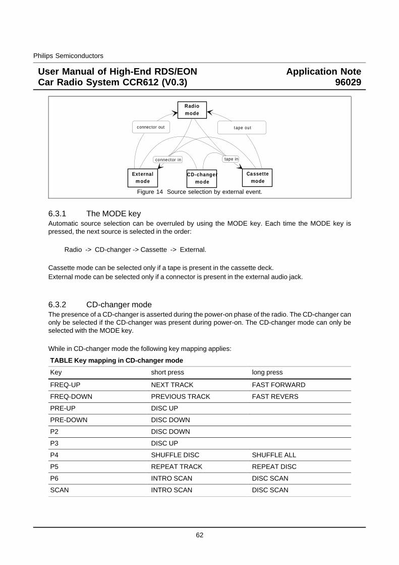
Philips Semiconductors
User Manual of High-End RDS/EONCar Radio System CCR612 (V0.3)
Application Note96029
Radiomode
Cassettemode
Externalmode
tape inconnector in
connector out t ape ou t
CD-changermo de
Figure 14 Source selection by external event.
6.3.1 The MODE keyAutomatic source selection can be overruled by using the MODE key. Each time the MODE key ispressed, the next source is selected in the order:
Radio -> CD-changer -> Cassette -> External.
Cassette mode can be selected only if a tape is present in the cassette deck.External mode can be selected only if a connector is present in the external audio jack.
6.3.2 CD-changer modeThe presence of a CD-changer is asserted during the power-on phase of the radio. The CD-changer canonly be selected if the CD-changer was present during power-on. The CD-changer mode can only beselected with the MODE key.
While in CD-changer mode the following key mapping applies:
TABLE Key mapping in CD-changer mode
Key short press long press
FREQ-UP NEXT TRACK FAST FORWARD
FREQ-DOWN PREVIOUS TRACK FAST REVERS
PRE-UP DISC UP
PRE-DOWN DISC DOWN
P2 DISC DOWN
P3 DISC UP
P4 SHUFFLE DISC SHUFFLE ALL
P5 REPEAT TRACK REPEAT DISC
P6 INTRO SCAN DISC SCAN
SCAN INTRO SCAN DISC SCAN
62
Philips Semiconductors
User Manual of High-End RDS/EONCar Radio System CCR612 (V0.3)
Application Note96029
6.3.3 Cassette functionsThe cassette interface is based on a mechanical tape deck. When a cassette is playing, the display willshow the text "PLAY >" or "PLAY <" indicating the play direction. During fast winding, no directioninformation is available. The display will show "CAS WIND". When fast winding for more than 4 seconds,the set will temporarily switch to radio mode.
While in cassette mode, the keys P-4, P-5/PRE-UP and P-6/PRE-DOWN control the functions AMS(Automatic Music Search), MTL (Metal/Chromium) and Dolby respectively. The keys toggle thecorresponding output pins, the function itself is executed by the cassette deck circuitry. When a functionis not available in the cassette deck, the corresponding pin must be connected to ground.The state of the AMS, ME/CR and Dolby functions is displayed by icons. If a TEA632x is installed thecassette solenoid and AMS pause function are available. The solenoid function takes care of playing inthe correct direction after switching to cassette mode and together with the AMS pause function, it takescare of controlling the AMS function. Search (in both directions) for the next music piece by detecting ablank area on the tape. If no TEA632x is installed (potentiometer sound control) the AMS function and thesolenoid function are not available. If the cassette drive does not have the AMS function the CAMS pinmust be connected to ground.
6.3.4 External audio sourceAn external audio input is available to connect e.g. a CD player. The external input jack has a switch tosense whether a connector is inserted. While the radio is in external mode, the text "EXTERNAL" is shownon the display. When no external audio selection is available the EXSTAT pin must be connected toGround.
6.4 Audio controlMost of the audio control facilities are available only if a digital sound and fader control chip (Sofac) isinstalled. If no digital sound control chip is used, the following signals should be used in combination withpotentiometer control:
- pin AUMUTE Mute status;- pin LOUDN Loudness status;- pin TA Traffic announcement or PTY alarm message in progress;- pin SEL0 / SEL1 Source selection.
The volume at power on is limited to -10 dB when digital sound control is available.
63
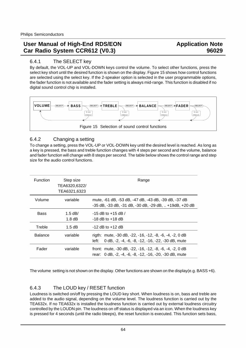
Philips Semiconductors
User Manual of High-End RDS/EONCar Radio System CCR612 (V0.3)
Application Note96029
6.4.1 The SELECT keyBy default, the VOL-UP and VOL-DOWN keys control the volume. To select other functions, press theselect key short until the desired function is shown on the display. Figure 15 shows how control functionsare selected using the select key. If the 2-speaker option is selected in the user programmable options,the fader function is not available and the fader setting is always mid-range. This function is disabled if nodigital sound control chip is installed.
S E L E C T BASS S E L E C T TREBLE S E L E C T BALANCE S E LE C T FADER S E L E C T
6 s e c
t i m e o u t
6 s e c
t i m e o u t
6 s e c
t i m e o u t
6 s e c
t i m e o u t
VOLUME
Figure 15 Selection of sound control functions
6.4.2 Changing a settingTo change a setting, press the VOL-UP or VOL-DOWN key until the desired level is reached. As long asa key is pressed, the bass and treble function changes with 4 steps per second and the volume, balanceand fader function will change with 8 steps per second. The table below shows the control range and stepsize for the audio control functions.
Function Step sizeTEA6320,6322/TEA6321,6323
Range
Volume variable mute, -61 dB, -53 dB, -47 dB, -43 dB, -39 dB, -37 dB-35 dB, -33 dB, -31 dB, -30 dB, -29 dB, .. +19dB, +20 dB
Bass 1.5 dB/1.8 dB
-15 dB to +15 dB /-18 dB to +18 dB
Treble 1.5 dB -12 dB to +12 dB
Balance variable rigth: mute, -30 dB, -22, -16, -12, -8, -6, -4, -2, 0 dBleft: 0 dB, -2, -4, -6, -8, -12, -16, -22, -30 dB, mute
Fader variable front: mute, -30 dB, -22, -16, -12, -8, -6, -4, -2, 0 dBrear: 0 dB, -2, -4, -6, -8, -12, -16, -20, -30 dB, mute
The volume setting is not shown on the display. Other functions are shown on the display(e.g. BASS +6).
6.4.3 The LOUD key / RESET functionLoudness is switched on/off by pressing the LOUD key short. When loudness is on, bass and treble areadded to the audio signal, depending on the volume level. The loudness function is carried out by theTEA632x. If no TEA632x is installed the loudness function is carried out by external loudness circuitrycontrolled by the LOUDN pin. The loudness on off status is displayed via an icon. When the loudness keyis pressed for 4 seconds (until the radio bleeps), the reset function is executed. This function sets bass,
64
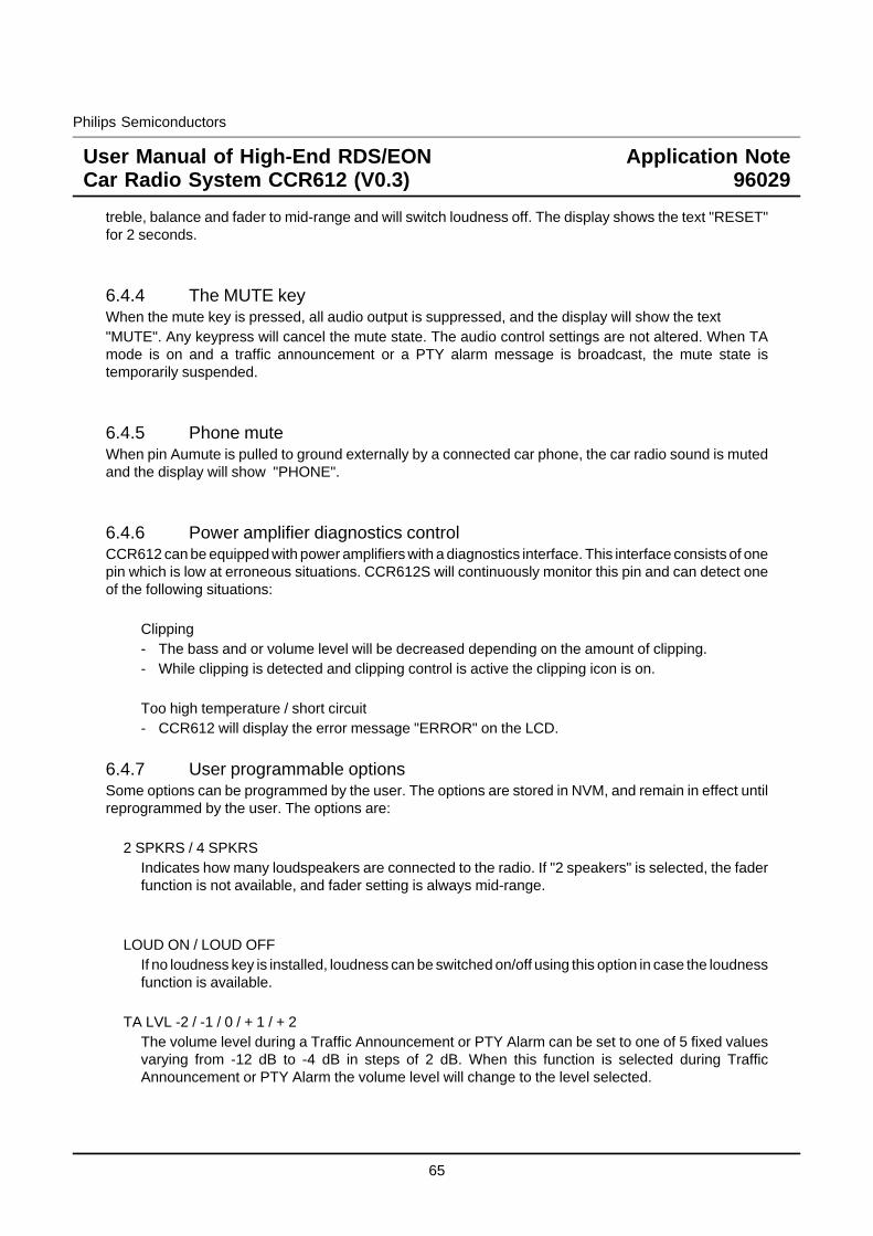
Philips Semiconductors
User Manual of High-End RDS/EONCar Radio System CCR612 (V0.3)
Application Note96029
treble, balance and fader to mid-range and will switch loudness off. The display shows the text "RESET"for 2 seconds.
6.4.4 The MUTE keyWhen the mute key is pressed, all audio output is suppressed, and the display will show the text"MUTE". Any keypress will cancel the mute state. The audio control settings are not altered. When TAmode is on and a traffic announcement or a PTY alarm message is broadcast, the mute state istemporarily suspended.
6.4.5 Phone muteWhen pin Aumute is pulled to ground externally by a connected car phone, the car radio sound is mutedand the display will show "PHONE".
6.4.6 Power amplifier diagnostics controlCCR612 can be equipped with power amplifiers with a diagnostics interface. This interface consists of onepin which is low at erroneous situations. CCR612S will continuously monitor this pin and can detect oneof the following situations:
Clipping- The bass and or volume level will be decreased depending on the amount of clipping.- While clipping is detected and clipping control is active the clipping icon is on.
Too high temperature / short circuit- CCR612 will display the error message "ERROR" on the LCD.
6.4.7 User programmable optionsSome options can be programmed by the user. The options are stored in NVM, and remain in effect untilreprogrammed by the user. The options are:
2 SPKRS / 4 SPKRSIndicates how many loudspeakers are connected to the radio. If "2 speakers" is selected, the faderfunction is not available, and fader setting is always mid-range.
LOUD ON / LOUD OFFIf no loudness key is installed, loudness can be switched on/off using this option in case the loudnessfunction is available.
TA LVL -2 / -1 / 0 / + 1 / + 2The volume level during a Traffic Announcement or PTY Alarm can be set to one of 5 fixed valuesvarying from -12 dB to -4 dB in steps of 2 dB. When this function is selected during TrafficAnnouncement or PTY Alarm the volume level will change to the level selected.
65
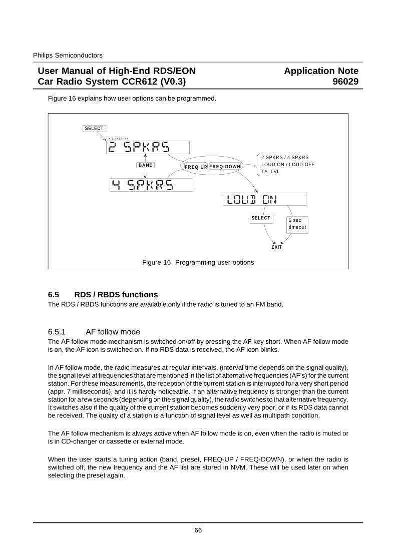
Philips Semiconductors
User Manual of High-End RDS/EONCar Radio System CCR612 (V0.3)
Application Note96029
Figure 16 explains how user options can be programmed.
SELECT
> 4 seconds
BA ND F R EQ U P F RE Q DO WN
2 SPKRS / 4 SPKRS
LOUD ON / LOUD OFFTA LVL
SELECT 6 sectimeout
EXIT
Figure 16 Programming user options
6.5 RDS / RBDS functionsThe RDS / RBDS functions are available only if the radio is tuned to an FM band.
6.5.1 AF follow modeThe AF follow mode mechanism is switched on/off by pressing the AF key short. When AF follow modeis on, the AF icon is switched on. If no RDS data is received, the AF icon blinks.
In AF follow mode, the radio measures at regular intervals, (interval time depends on the signal quality),the signal level at frequencies that are mentioned in the list of alternative frequencies (AF’s) for the currentstation. For these measurements, the reception of the current station is interrupted for a very short period(appr. 7 milliseconds), and it is hardly noticeable. If an alternative frequency is stronger than the currentstation for a few seconds (depending on the signal quality), the radio switches to that alternative frequency.It switches also if the quality of the current station becomes suddenly very poor, or if its RDS data cannotbe received. The quality of a station is a function of signal level as well as multipath condition.
The AF follow mechanism is always active when AF follow mode is on, even when the radio is muted oris in CD-changer or cassette or external mode.
When the user starts a tuning action (band, preset, FREQ-UP / FREQ-DOWN), or when the radio isswitched off, the new frequency and the AF list are stored in NVM. These will be used later on whenselecting the preset again.
66
Philips Semiconductors
User Manual of High-End RDS/EONCar Radio System CCR612 (V0.3)
Application Note96029
6.5.2 PTY functionsCCR612 offers the user the possibility to search for a station with a certain user selected PTY code. Whenkey PTY is pressed, the currently received PTY code is displayed. If no PTY code is received the displaywill show "NO PTY" . By pressing the key FREQ-UP or FREQ-DOWN, the user can select the PTY codeof his choice. When key PTY is pressed for 2 seconds (while the radio is in the PTY selecting mode), theradio will start a PTY search for the selected PTY code. Figure 17 shows how to select a programme type.Only one programme type can be selected.
PTY
FREQ UP FREQ DOWN
N E W SA F F A I R SI N F OS P O R TE D U C A T ED R A M AC U L T U R ES C I E N C EV A R I E DP O P MR O C K MM. O. R . ML I G H T MC L A S S I CO T H E R M
A L A R MPTY
6 S ec t im eo u t o ro t h e r k ey ,
c an ce l PTY s e l ec tm o d e
St a r t PTY S can in u p d irec t ion
RDS RBDSN E W SI NF ORMS P O RT ST A L KR OC KCLS ROCKA DL T HI TS OF T RCKT OP 4 0COUNT RYOL DI E SS O F TNOS TA L GAJ A Z ZCLA S S ICLR & BS OF T R& BL A NGUA GEREL MUSI CREL T AL KP E RSNL T YP UBL I C
T E S TA LE RT !
> 2 sec.
Figure 17 Selecting the PTY code
PTY codes "ALARM" / "TEST" / "ALERT!" can not be selected. The radio will respond to a PTY alarmmessage in the same way as a TA traffic announcement, independent of TA mode. For the USAapplication the RBDS PTY table is used.During a PTY search the PTY icon blinks. When the radio receives a PTY code, the PTY icon is on.When TA mode is on during a PTY search, the radio will first try to find a station which is a traffic stationwith the correct PTY code. When no such station can be found (even not in Dx mode), the radio will drop
67
Philips Semiconductors
User Manual of High-End RDS/EONCar Radio System CCR612 (V0.3)
Application Note96029
the TA requirement and search only for a station with the correct PTY code. If still no station can be found,the radio will return to its original tuned frequency.
6.5.3 Traffic announcements
Traffic announcements have a special meaning only when TA mode is on.
To switch TA mode on/off, press the TA key. When TA mode is on, the TA icon is on. If the current stationis not a traffic station, the TP icon blinks, and a warning bleep is generated every 30 seconds.
If TA mode is on, the next happens when a traffic announcement is broadcast:
1. If the traffic announcement is detected via EON, the radio will switch to the linked programme servicetransmitting the traffic announcement. The radio will stay at least 4 seconds on this programmebefore switching back to the original programme to give the broadcaster time to synchronise the RDSTP and TA data over its network.AF follow mode is disabled during an EON traffic announcement.
2. If the radio is in CD-changer, cassette mode or in external mode, it switches temporarily to radiomode, and the display will show the programme service name of the received station.
3. If the radio is muted, it is temporarily de-muted, and the "MUTE" message is removed from thedisplay.
4. If the volume was low, it is raised to the TA volume level as installed under the user options (see:user programmable options). Also, the TA output pin is made low.
5. The TA icon blinks. In case of a traffic announcement on an EON linked station, the EON icon willalso blink.
At the end of the traffic announcement, the old situation is restored again (after an EON trafficannouncement the radio will switch back to the original station). If the user has not changed the volumesetting, it is restored to the value before the traffic announcement. If the volume level was changed, thenew value will be retained.
The current traffic announcement can be cancelled by pressing the TA key, the TA mode remains on.
6.5.4 PTY alarm broadcastsA PTY alarm message is treated the same way as a traffic announcement. A PTY alarm message willbreak-in, even when TA mode is off.
68
Philips Semiconductors
User Manual of High-End RDS/EONCar Radio System CCR612 (V0.3)
Application Note96029
7 RDS / RBDS FACILITIES.As soon as the radio is steadily tuned to an FM station, it will start collecting RDS information. The nextitems are extracted from the stream of RDS data:
- PI Programme Identification code;- PS Programme Service name;- PTY Programme TYpe code;- TP Traffic Programme bit;- TA Traffic Announcement bit;- AF Alternative Frequency list;- EON Enhanced Other Network information.
Most data is validated, e.g. the same data must be received twice before it is accepted as a new value.
7.1 Programme Identification codeThe PI code is invisible for the user. It is used to check whether the correct station is received after apreset is selected, or when the AF follow mechanism switches to an alternative frequency.When a station is stored in NVM, also its PI code is stored. When the same preset is selected again, theradio verifies the PI code. If the PI code is not correct, and AF follow mode is on, the radio will search fora station with the right PI code, first by scanning all available alternative frequencies, then if after a timeoutof 6 seconds the PI code is still not correct, a search tuning operation is started.During AST Search, the PI code is used to avoid that the same programme is stored at different presets,when it can be received on more than one frequency. For USA application (RBDS) the regional functionwill only work for PI codes above B000hex. PI codes below B000hex do not have regional variants. AFswitching is only allowed to stations with exactly the same PI code.
7.2 Programme Service nameBy default, the radio will display the received Programme Service name as soon as it is available. The PSname is stored in the preset memory locations. The name is then immediately displayed when a presetstation is selected.Tuning frequency instead of PS name is displayed when the radio is in manual tuning mode. Also, bymeans of the display key, the radio can be forced to display PTY code, frequency and PS namerespectively.
7.3 Programme TYpePTY is a code for the kind of programme that is broadcast. Figure 17 shows the names of PTY codes thatare defined for RDS. CCR612 can display the PTY currently received, and it can search for a station witha specific PTY code. The user can select a PTY code and start a scan for a station transmitting this PTYcode.
69
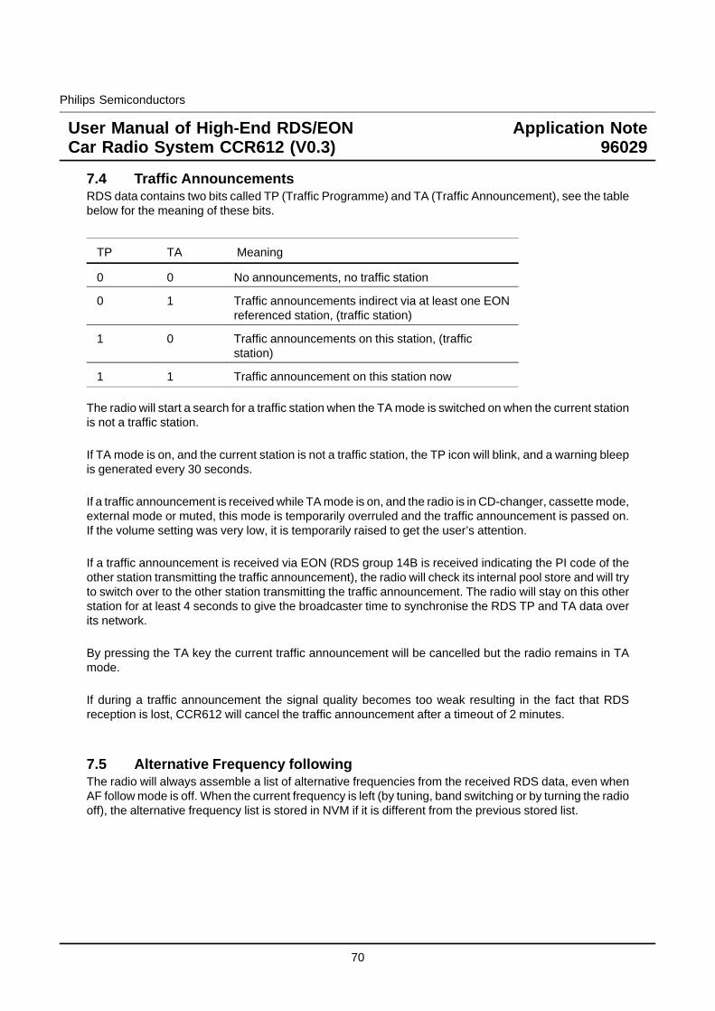
Philips Semiconductors
User Manual of High-End RDS/EONCar Radio System CCR612 (V0.3)
Application Note96029
7.4 Traffic AnnouncementsRDS data contains two bits called TP (Traffic Programme) and TA (Traffic Announcement), see the tablebelow for the meaning of these bits.
TP TA Meaning
0 0 No announcements, no traffic station
0 1 Traffic announcements indirect via at least one EONreferenced station, (traffic station)
1 0 Traffic announcements on this station, (trafficstation)
1 1 Traffic announcement on this station now
The radio will start a search for a traffic station when the TA mode is switched on when the current stationis not a traffic station.
If TA mode is on, and the current station is not a traffic station, the TP icon will blink, and a warning bleepis generated every 30 seconds.
If a traffic announcement is received while TA mode is on, and the radio is in CD-changer, cassette mode,external mode or muted, this mode is temporarily overruled and the traffic announcement is passed on.If the volume setting was very low, it is temporarily raised to get the user’s attention.
If a traffic announcement is received via EON (RDS group 14B is received indicating the PI code of theother station transmitting the traffic announcement), the radio will check its internal pool store and will tryto switch over to the other station transmitting the traffic announcement. The radio will stay on this otherstation for at least 4 seconds to give the broadcaster time to synchronise the RDS TP and TA data overits network.
By pressing the TA key the current traffic announcement will be cancelled but the radio remains in TAmode.
If during a traffic announcement the signal quality becomes too weak resulting in the fact that RDSreception is lost, CCR612 will cancel the traffic announcement after a timeout of 2 minutes.
7.5 Alternative Frequency followingThe radio will always assemble a list of alternative frequencies from the received RDS data, even whenAF follow mode is off. When the current frequency is left (by tuning, band switching or by turning the radiooff), the alternative frequency list is stored in NVM if it is different from the previous stored list.
70
Philips Semiconductors
User Manual of High-End RDS/EONCar Radio System CCR612 (V0.3)
Application Note96029
When AF follow mode is on, the next actions are taken:
1. When selecting a preset, the radio will load the AF list from NVM, and measure the signal strengthof the primary frequency and all alternative frequencies. It will then select the strongest station withthe correct PI code, before the radio is de-muted.(PI codes are compared with the value stored in the preset data in NVM.)If no station with the correct PI code is found, after 6 seconds the radio will start a search tuning fora station with the correct PI code. If still not found, it will accept the new station, but it will not updatethe PI code stored in NVM.Search tuning can be cancelled by switching AF follow mode off or by pressing the AUTO / MANUALkey. The radio will then return to the original frequency.
2. At regular intervals - depending on the signal strength of the current station - the signal strength ofalternative frequencies is measured. The interval varies from appr. 80 seconds when the signal levelof the current station is very strong to appr. 3 seconds when it is very weak.
3. When for a certain time an AF is stronger than the current frequency, or when the current frequencybecomes suddenly unacceptable e.g. due to multipath, the radio switches to the best alternativefrequency.When the programme service is left (by tuning, band switching or by turning the radio off), the newfrequency is stored in NVM as the primary frequency for that preset.
The AF follow algorithm has provisions for special circumstances such as:
- Mountains and buildings. All signal strengths vary rapidly due to multipath distortion. Switch whenthe multipath distortion level becomes unacceptable.
- Loss of RDS data or station changes PI code. Select an alternative frequency with correct PIcode.
The "quality" of a station is a value that is based on signal level as well as multipath level read fromthe TEA6822 by means of the I2C-bus.
7.6 EON preset updateWhen the tuned station transmits EON information, the alternative frequencies stored for the stationpresets are updated via EON. Only those alternative frequency lists of station presets can be updatedwhose PI codes match one of the PI codes transmitted via EON. Whether or not regional variants of thePI code are taken into account depends on the status of the regional selection. If the regional selectionis switched on, the transmitted PI code must exactly match the PI code to update.
If after travelling any distance while tuned to a programme service, a user selects a preset for anotherstation which is cross-referenced by EON-information, CCR612 has to find an acceptable frequency forthe new selected station in the new area, without resorting to a PI search. This should occur regardlessof the distance travelled, assuming of course that the station is transmitted in the new area.
71
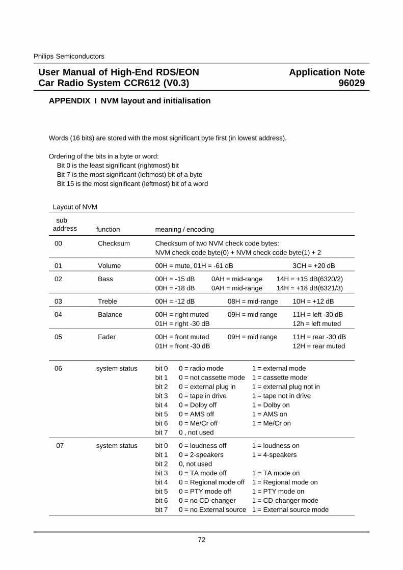
Philips Semiconductors
User Manual of High-End RDS/EONCar Radio System CCR612 (V0.3)
Application Note96029
APPENDIX I NVM layout and initialisation
Words (16 bits) are stored with the most significant byte first (in lowest address).
Ordering of the bits in a byte or word:Bit 0 is the least significant (rightmost) bitBit 7 is the most significant (leftmost) bit of a byteBit 15 is the most significant (leftmost) bit of a word
Layout of NVM
subaddress function meaning / encoding
00 Checksum Checksum of two NVM check code bytes:NVM check code byte(0) + NVM check code byte(1) + 2
01 Volume 00H = mute, 01H = -61 dB 3CH = +20 dB
02 Bass 00H = -15 dB 0AH = mid-range 14H = +15 dB(6320/2)00H = -18 dB 0AH = mid-range 14H = +18 dB(6321/3)
03 Treble 00H = -12 dB 08H = mid-range 10H = +12 dB
04 Balance 00H = right muted 09H = mid range 11H = left -30 dB01H = right -30 dB 12h = left muted
05 Fader 00H = front muted 09H = mid range 11H = rear -30 dB01H = front -30 dB 12H = rear muted
06 system status bit 0 0 = radio mode 1 = external modebit 1 0 = not cassette mode 1 = cassette modebit 2 0 = external plug in 1 = external plug not inbit 3 0 = tape in drive 1 = tape not in drivebit 4 0 = Dolby off 1 = Dolby onbit 5 0 = AMS off 1 = AMS onbit 6 0 = Me/Cr off 1 = Me/Cr onbit 7 0 , not used
07 system status bit 0 0 = loudness off 1 = loudness onbit 1 0 = 2-speakers 1 = 4-speakersbit 2 0, not usedbit 3 0 = TA mode off 1 = TA mode onbit 4 0 = Regional mode off 1 = Regional mode onbit 5 0 = PTY mode off 1 = PTY mode onbit 6 0 = no CD-changer 1 = CD-changer modebit 7 0 = no External source 1 = External source mode
72
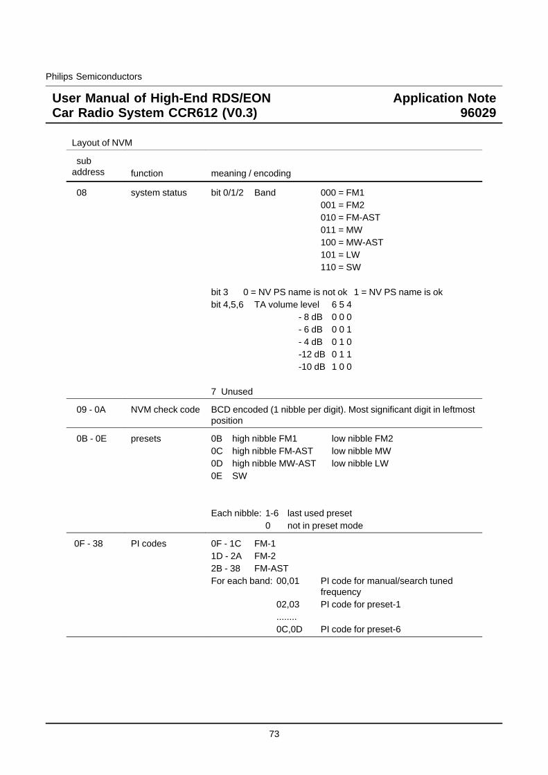
Philips Semiconductors
User Manual of High-End RDS/EONCar Radio System CCR612 (V0.3)
Application Note96029
Layout of NVM
subaddress function meaning / encoding
08 system status bit 0/1/2 Band 000 = FM1001 = FM2010 = FM-AST011 = MW100 = MW-AST101 = LW110 = SW
bit 3 0 = NV PS name is not ok 1 = NV PS name is okbit 4,5,6 TA volume level 6 5 4
- 8 dB 0 0 0- 6 dB 0 0 1- 4 dB 0 1 0-12 dB 0 1 1-10 dB 1 0 0
7 Unused
09 - 0A NVM check code BCD encoded (1 nibble per digit). Most significant digit in leftmostposition
0B - 0E presets 0B high nibble FM1 low nibble FM20C high nibble FM-AST low nibble MW0D high nibble MW-AST low nibble LW0E SW
Each nibble: 1-6 last used preset0 not in preset mode
0F - 38 PI codes 0F - 1C FM-11D - 2A FM-22B - 38 FM-ASTFor each band: 00,01 PI code for manual/search tuned
frequency02,03 PI code for preset-1........0C,0D PI code for preset-6
73
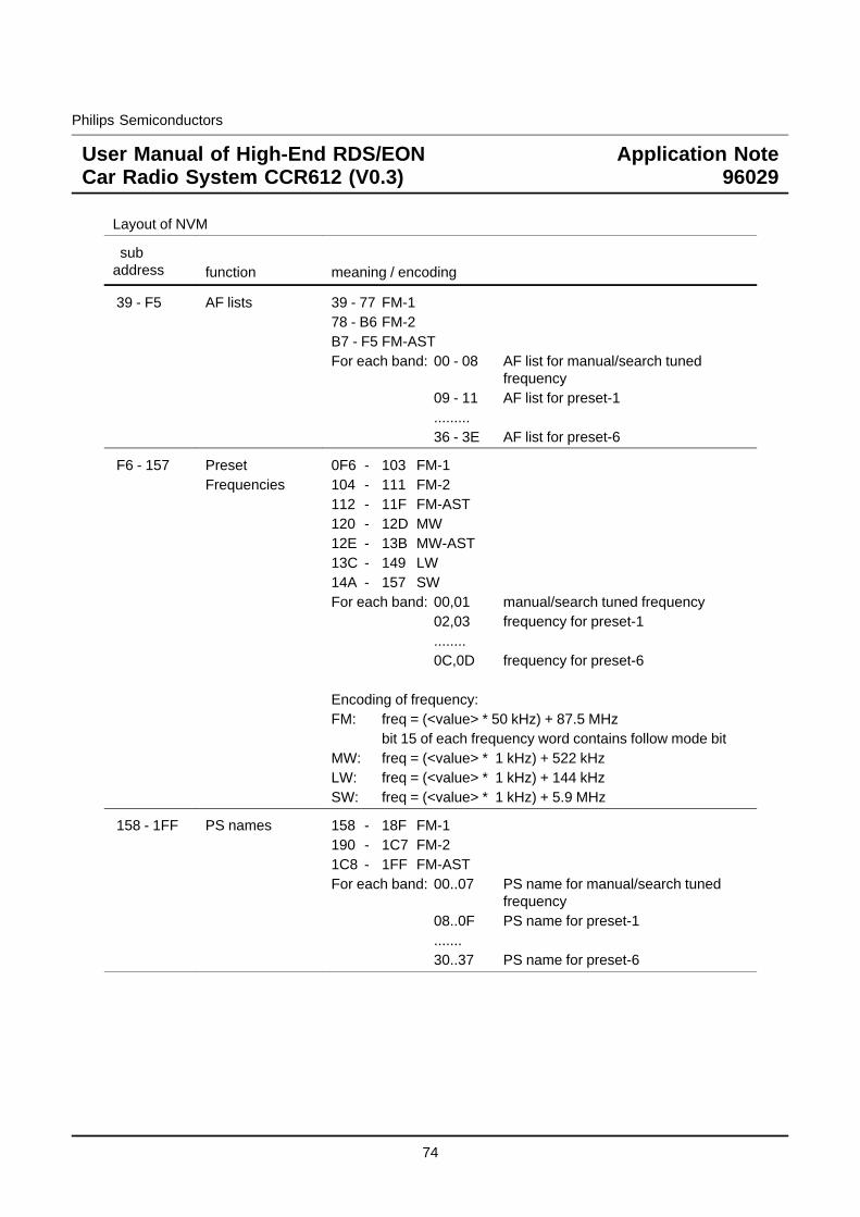
Philips Semiconductors
User Manual of High-End RDS/EONCar Radio System CCR612 (V0.3)
Application Note96029
Layout of NVM
subaddress function meaning / encoding
39 - F5 AF lists 39 - 77 FM-178 - B6 FM-2B7 - F5 FM-ASTFor each band: 00 - 08 AF list for manual/search tuned
frequency09 - 11 AF list for preset-1.........36 - 3E AF list for preset-6
F6 - 157 PresetFrequencies
0F6 - 103 FM-1104 - 111 FM-2112 - 11F FM-AST120 - 12D MW12E - 13B MW-AST13C - 149 LW14A - 157 SWFor each band: 00,01 manual/search tuned frequency
02,03 frequency for preset-1........0C,0D frequency for preset-6
Encoding of frequency:FM: freq = (<value> * 50 kHz) + 87.5 MHz
bit 15 of each frequency word contains follow mode bitMW: freq = (<value> * 1 kHz) + 522 kHzLW: freq = (<value> * 1 kHz) + 144 kHzSW: freq = (<value> * 1 kHz) + 5.9 MHz
158 - 1FF PS names 158 - 18F FM-1190 - 1C7 FM-21C8 - 1FF FM-ASTFor each band: 00..07 PS name for manual/search tuned
frequency08..0F PS name for preset-1.......30..37 PS name for preset-6
74
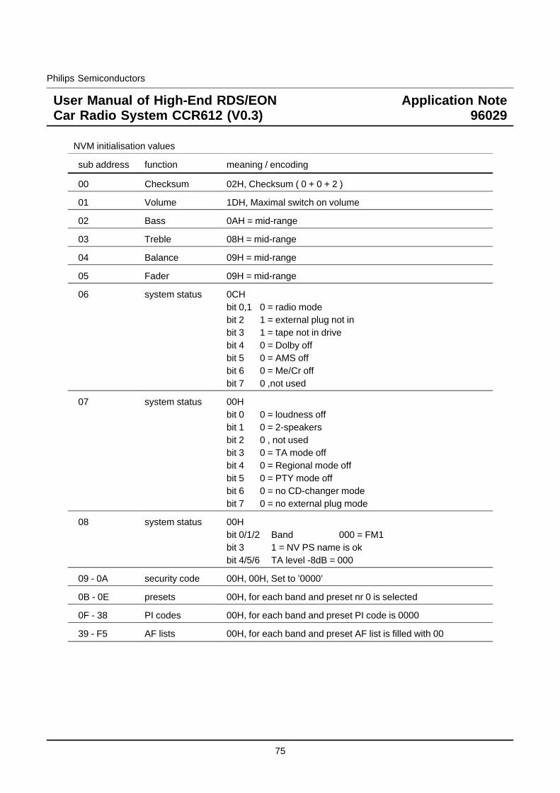
Philips Semiconductors
User Manual of High-End RDS/EONCar Radio System CCR612 (V0.3)
Application Note96029
NVM initialisation values
sub address function meaning / encoding
00 Checksum 02H, Checksum ( 0 + 0 + 2 )
01 Volume 1DH, Maximal switch on volume
02 Bass 0AH = mid-range
03 Treble 08H = mid-range
04 Balance 09H = mid-range
05 Fader 09H = mid-range
06 system status 0CHbit 0,1 0 = radio modebit 2 1 = external plug not inbit 3 1 = tape not in drivebit 4 0 = Dolby offbit 5 0 = AMS offbit 6 0 = Me/Cr offbit 7 0 ,not used
07 system status 00Hbit 0 0 = loudness offbit 1 0 = 2-speakersbit 2 0 , not usedbit 3 0 = TA mode offbit 4 0 = Regional mode offbit 5 0 = PTY mode offbit 6 0 = no CD-changer modebit 7 0 = no external plug mode
08 system status 00Hbit 0/1/2 Band 000 = FM1bit 3 1 = NV PS name is okbit 4/5/6 TA level -8dB = 000
09 - 0A security code 00H, 00H, Set to ’0000’
0B - 0E presets 00H, for each band and preset nr 0 is selected
0F - 38 PI codes 00H, for each band and preset PI code is 0000
39 - F5 AF lists 00H, for each band and preset AF list is filled with 00
75
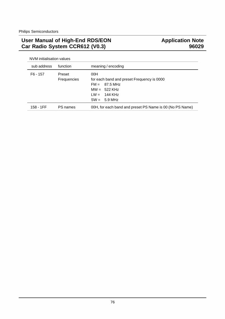
Philips Semiconductors
User Manual of High-End RDS/EONCar Radio System CCR612 (V0.3)
Application Note96029
NVM initialisation values
sub address function meaning / encoding
F6 - 157 PresetFrequencies
00Hfor each band and preset Frequency is 0000FM = 87.5 MHzMW = 522 KHzLW = 144 KHzSW = 5.9 MHz
158 - 1FF PS names 00H, for each band and preset PS Name is 00 (No PS Name)
76
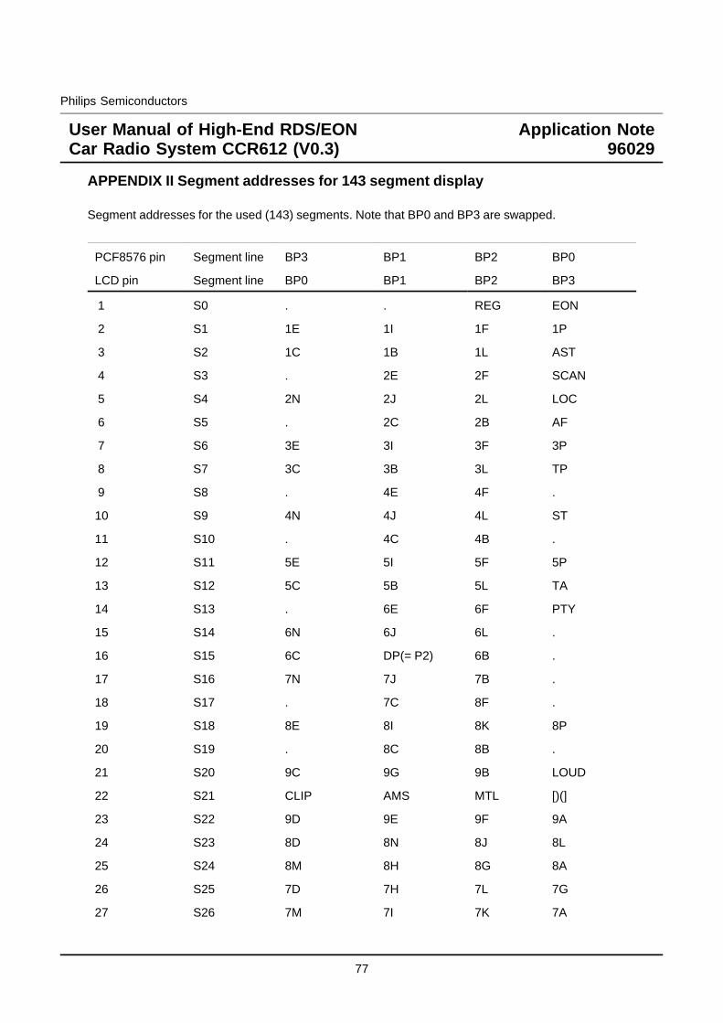
Philips Semiconductors
User Manual of High-End RDS/EONCar Radio System CCR612 (V0.3)
Application Note96029
APPENDIX II Segment addresses for 143 segment display
Segment addresses for the used (143) segments. Note that BP0 and BP3 are swapped.
PCF8576 pin Segment line BP3 BP1 BP2 BP0
LCD pin Segment line BP0 BP1 BP2 BP3
1 S0 . . REG EON
2 S1 1E 1I 1F 1P
3 S2 1C 1B 1L AST
4 S3 . 2E 2F SCAN
5 S4 2N 2J 2L LOC
6 S5 . 2C 2B AF
7 S6 3E 3I 3F 3P
8 S7 3C 3B 3L TP
9 S8 . 4E 4F .
10 S9 4N 4J 4L ST
11 S10 . 4C 4B .
12 S11 5E 5I 5F 5P
13 S12 5C 5B 5L TA
14 S13 . 6E 6F PTY
15 S14 6N 6J 6L .
16 S15 6C DP(= P2) 6B .
17 S16 7N 7J 7B .
18 S17 . 7C 8F .
19 S18 8E 8I 8K 8P
20 S19 . 8C 8B .
21 S20 9C 9G 9B LOUD
22 S21 CLIP AMS MTL [)(]
23 S22 9D 9E 9F 9A
24 S23 8D 8N 8J 8L
25 S24 8M 8H 8G 8A
26 S25 7D 7H 7L 7G
27 S26 7M 7I 7K 7A
77
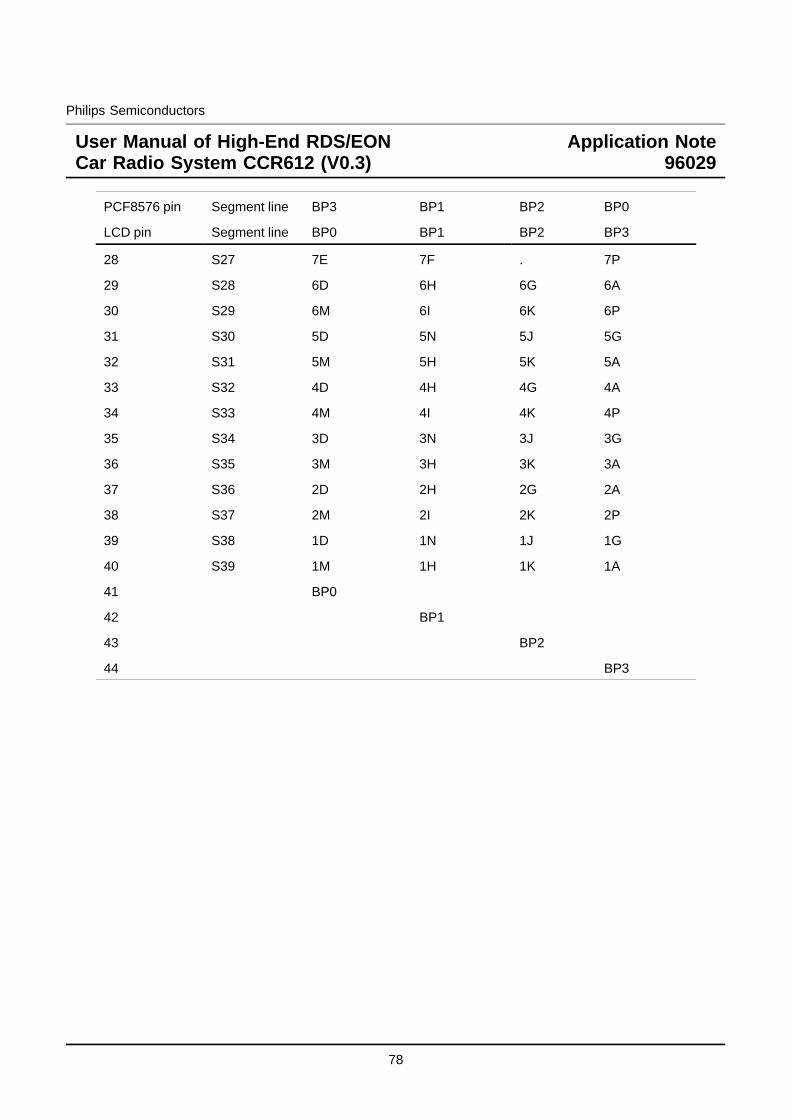
Philips Semiconductors
User Manual of High-End RDS/EONCar Radio System CCR612 (V0.3)
Application Note96029
PCF8576 pin Segment line BP3 BP1 BP2 BP0
LCD pin Segment line BP0 BP1 BP2 BP3
28 S27 7E 7F . 7P
29 S28 6D 6H 6G 6A
30 S29 6M 6I 6K 6P
31 S30 5D 5N 5J 5G
32 S31 5M 5H 5K 5A
33 S32 4D 4H 4G 4A
34 S33 4M 4I 4K 4P
35 S34 3D 3N 3J 3G
36 S35 3M 3H 3K 3A
37 S36 2D 2H 2G 2A
38 S37 2M 2I 2K 2P
39 S38 1D 1N 1J 1G
40 S39 1M 1H 1K 1A
41 BP0
42 BP1
43 BP2
44 BP3
78
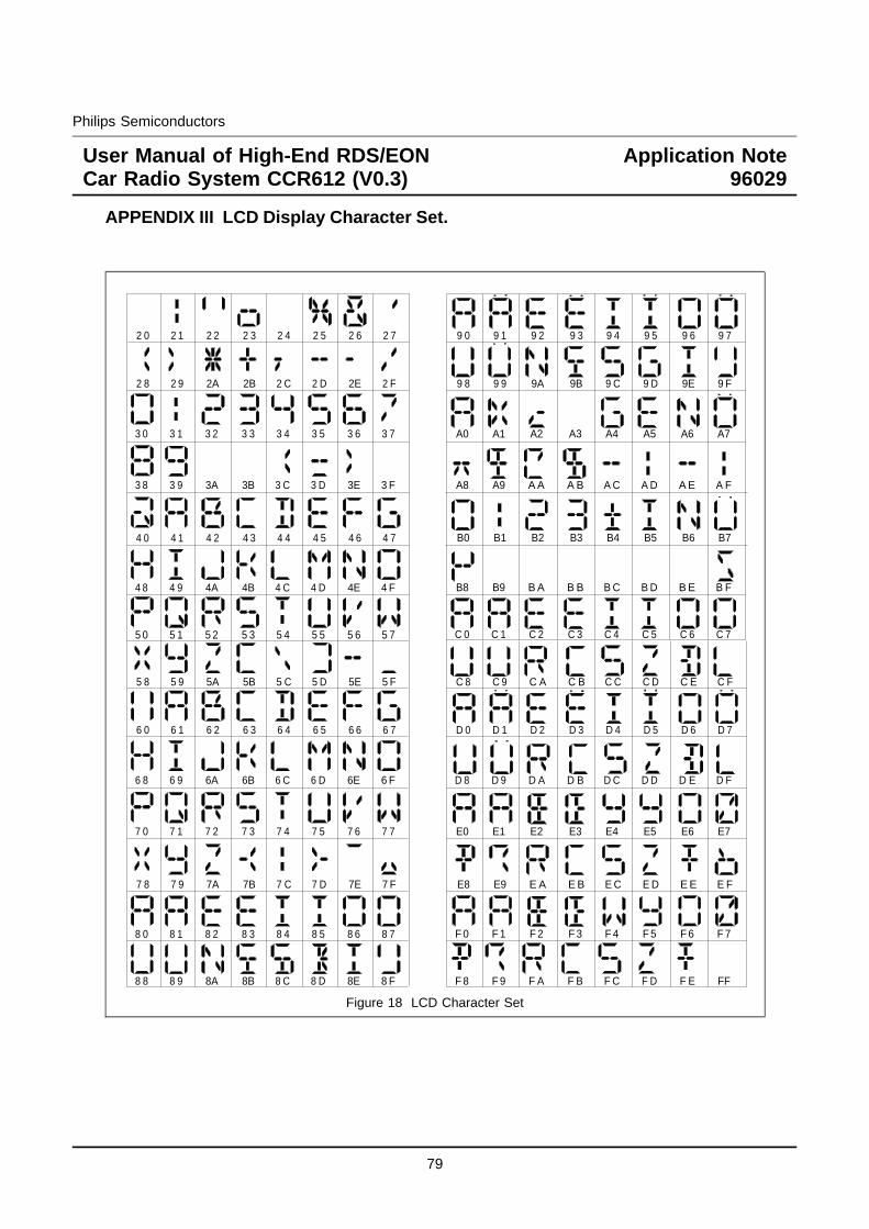
Philips Semiconductors
User Manual of High-End RDS/EONCar Radio System CCR612 (V0.3)
Application Note96029
APPENDIX III LCD Display Character Set.
2 0 2 1 2 2 2 3 2 4 2 5 2 6 2 7
2 8 2 9 2A 2B 2 C 2 D 2E 2 F
3 0 3 1 3 2 3 3 3 4 3 5 3 6 3 7
3 8 3 9 3A 3B 3 C 3 D 3E 3 F
4 0 4 1 4 2 4 3 4 4 4 5 4 6 4 7
4 8 4 9 4A 4B 4 C 4 D 4E 4 F
5 0 5 1 5 2 5 3 5 4 5 5 5 6 5 7
5 8 5 9 5A 5B 5 C 5 D 5E 5 F
6 0 6 1 6 2 6 3 6 4 6 5 6 6 6 7
6 8 6 9 6A 6B 6 C 6 D 6E 6 F
7 0 7 1 7 2 7 3 7 4 7 5 7 6 7 7
7 8 7 9 7A 7B 7 C 7 D 7E 7 F
8 0 8 1 8 2 8 3 8 4 8 5 8 6 8 7
8 8 8 9 8A 8B 8 C 8 D 8E 8 F
9 0 9 1 9 2 9 3 9 4 9 5 9 6 9 7
9 8 9 9 9A 9B 9 C 9 D 9E 9 F
A0 A1 A2 A3 A4 A5 A6 A7
A8 A9 A A A B A C A D A E A F
B0 B1 B2 B3 B4 B5 B6 B7
B8 B9 B A B B B C B D B E B F
C 0 C 1 C 2 C 3 C 4 C 5 C 6 C 7
C 8 C 9 C A C B C C C D C E C F
D 0 D 1 D 2 D 3 D 4 D 5 D 6 D 7
D 8 D 9 D A D B D C D D D E D F
E0 E1 E2 E3 E4 E5 E6 E7
E8 E9 E A E B E C E D E E E F
F 0 F 1 F 2 F 3 F 4 F 5 F 6 F 7
F 8 F 9 F A F B F C F D F E FF
Figure 18 LCD Character Set
79

Philips Semiconductors
User Manual of High-End RDS/EONCar Radio System CCR612 (V0.3)
Application Note96029
APPENDIX IV CIRCUIT DIAGRAMS
80

Philips Semiconductors
User Manual of High-End RDS/EONCar Radio System CCR612 (V0.3)
Application Note96029
dummy page for MAIN BOARD PART 1A
81

Philips Semiconductors
User Manual of High-End RDS/EONCar Radio System CCR612 (V0.3)
Application Note96029
dummy page for MAIN BOARD PART 1B
82

Philips Semiconductors
User Manual of High-End RDS/EONCar Radio System CCR612 (V0.3)
Application Note96029
dummy page for MAIN BOARD PART 1C
83

Philips Semiconductors
User Manual of High-End RDS/EONCar Radio System CCR612 (V0.3)
Application Note96029
dummy page for MAIN BOARD PART 2A
84

Philips Semiconductors
User Manual of High-End RDS/EONCar Radio System CCR612 (V0.3)
Application Note96029
dummy page for MAIN BOARD PART 2B
85

Philips Semiconductors
User Manual of High-End RDS/EONCar Radio System CCR612 (V0.3)
Application Note96029
dummy page for MAIN BOARD PART 3
86

Philips Semiconductors
User Manual of High-End RDS/EONCar Radio System CCR612 (V0.3)
Application Note96029
dummy page for FRONT BOARD PART FP-1A
87

Philips Semiconductors
User Manual of High-End RDS/EONCar Radio System CCR612 (V0.3)
Application Note96029
dummy page for FRONT BOARD PART FP-1B
88

Philips Semiconductors
User Manual of High-End RDS/EONCar Radio System CCR612 (V0.3)
Application Note96029
dummy page for ICE MODULE EURO 1
89

Philips Semiconductors
User Manual of High-End RDS/EONCar Radio System CCR612 (V0.3)
Application Note96029
dummy page for CCR612 mainboard pcb top
90

Philips Semiconductors
User Manual of High-End RDS/EONCar Radio System CCR612 (V0.3)
Application Note96029
dummy page for CCR612 mainboard pcb bottom
91

Philips Semiconductors
User Manual of High-End RDS/EONCar Radio System CCR612 (V0.3)
Application Note96029
dummy page for ICE module pcb
92

Philips Semiconductors
User Manual of High-End RDS/EONCar Radio System CCR612 (V0.3)
Application Note96029
dummy page for front panel top
93

Philips Semiconductors
User Manual of High-End RDS/EONCar Radio System CCR612 (V0.3)
Application Note96029
dummy page for SUB BOARD PACS
94