Embed Size (px)
Citation preview
VORTEXCOMPRESSORCONTROLLER
MAM860(Ⅳ)
USER
MANUAL
Shenzhen Plot Electronic Co., LtdAddress:4-5F,5 Bldg,Highstar Industry Park,Gangtou Community,
Bantian,Longgang District,Shenzhen City,ChinaTelephone:(+86 0755)83173599 / 83172822 Postal code:518129Fax:(+86 0755)83172966 E-mail:[email protected] site:www.pltsz.com
VOTE OF THANKS
Thank you for your trustworthy and select of PLOT air compressor controller !
Shenzhen Plot Electronic Co., Ltd specializes on the manufacture and R&D of air
compressor controller. We are devoted to win customer trust through our high quality
products and service.
We try our best to ensure the completeness and correctness of the manual, but PLOT
Company shall reserve the rights for continuous research and improvement on its products
and assume no obligation for the modification and improvement on the previously
delivered products. The design of products is subject to the change without notice.
Please feel free to contact our after-sale service center if you encounter any problem
with our product.
You are always welcome to make suggestions and advices!
CONTENT
1、BASIC OPERATION........................................................................................................................................................ 4
1、OVERVIEW:.................................................................................................................................................................... 42、BUTTON EXPLANATION.....................................................................................................................................................43、STATUS DISPLAY AND OPERATION.................................................................................................................................... 54、OPERATING PARAMETER AND MENU................................................................................................................................ 65、USER PARAMETER VIEW AND MODIFICATION................................................................................................................... 66、FACTORY PARAMETER VIEW ANDMODIFICATION..............................................................................................................97、CALIBRATION PARAMETER..............................................................................................................................................118、OPERATING AUTHORIZATION AND PASSWORD................................................................................................................ 13
2, CONTROLLER FUNCTION AND TECHNICALPARAMETER................................................................................. 13
3,INSTALLATION................................................................................................................................................................14
1、MECHANICAL INSTALLATION.......................................................................................................................................... 142、CONTROLLER INSTALLATION...........................................................................................................................................14
4,SCHEMATIC DIAGRAM................................................................................................................................................. 16
1、Basic Operation
1、Overview:
Vortex compressor controller can control compressor to operate automatically including pressure&temperatureauto control,compressor error information display,breakdown protection and block mode function.Each page of LCDpanel contain 4 lines.User can check and set parameter through HMI.
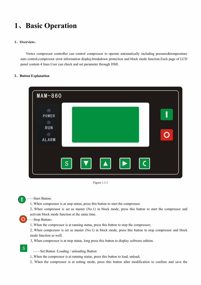
2、Button Explanation
Figure 1.1.1
——Start Button:1, When compressor is at stop status, press this button to start the compressor.2, When compressor is set as master (No.1) in block mode, press this button to start the compressor andactivate block mode function at the same time.
——Stop Button:1, When the compressor is at running status, press this button to stop the compressor;2, When compressor is set as master (No.1) in block mode, press this button to stop compressor and blockmode function as well;3, When compressor is at stop status, long press this button to display software edition.
——Set Button /Loading / unloading Button:1, When the compressor is at running status, press this button to load, unload;2, When the compressor is at setting mode, press this button after modification to confirm and save the
modified data.
——Move down button / Decreasing button:1, When viewing the menu, press this button to move downward the cursor;2,When modifying data, press this button to decrease the data at current position.
——Move up button/Increasing button:1, When viewing the menu, press this button to move upward the cursor;2, When modifying data, press this button to increase the data at current position.
——Shift button /Enter button:1, When modifying data, press this button to move to the next data bit;2, When select menu, press this button to switch to submenu. If no submenu available, the controller willshift to data setting mode.
——Return button / Reset button:1, When modifying data, press this button to exist data setting mode;2, When viewing the menu, press this button to return to previous menu;3, When the controller is at failure stop status, long press this button to reset.
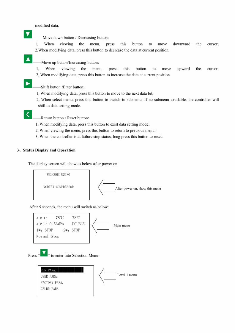
3、Status Display and Operation
The display screen will show as below after power on:
After power on, show this menu
After 5 seconds, the menu will switch as below:
Main menu
Press “ ” to enter into Selection Menu:
Level 1 menu
WELCOME USING
VORTEX COMPRESSOR
AIR T: 78℃ 78℃
AIR P: 0.53MPa DOUBLE
1#:STOP 2#:STOP
Normal Stop
RUN PARA.
USER PARA.
FACTORY PARA.
CALBR PARA.
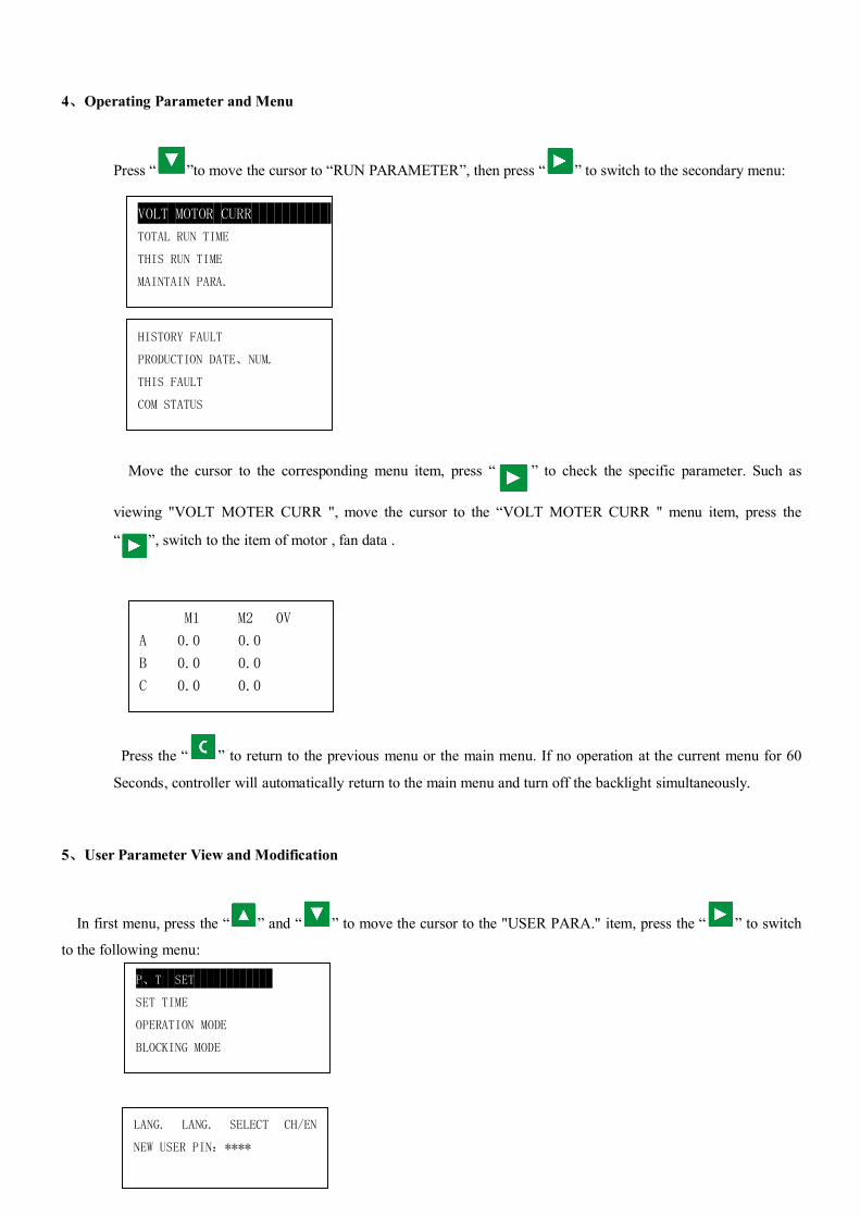
4、Operating Parameter and Menu
Press “ ”to move the cursor to “RUN PARAMETER”, then press “ ” to switch to the secondary menu:
Move the cursor to the corresponding menu item, press “ ” to check the specific parameter. Such as
viewing "VOLT MOTER CURR ", move the cursor to the “VOLT MOTER CURR " menu item, press the
“ ”, switch to the item of motor , fan data .
Press the “ ” to return to the previous menu or the main menu. If no operation at the current menu for 60
Seconds, controller will automatically return to the main menu and turn off the backlight simultaneously.
5、User Parameter View and Modification
In first menu, press the “ ” and “ ” to move the cursor to the "USER PARA." item, press the “ ” to switch
to the following menu:
VOLT MOTOR CURR
TOTAL RUN TIME
THIS RUN TIME
MAINTAIN PARA.
M1 M2 0V
A 0.0 0.0
B 0.0 0.0
C 0.0 0.0
HISTORY FAULT
PRODUCTION DATE、NUM.
THIS FAULT
COM STATUS
P、T SET
SET TIME
OPERATION MODE
BLOCKING MODE
LANG. LANG. SELECT CH/EN
NEW USER PIN:****
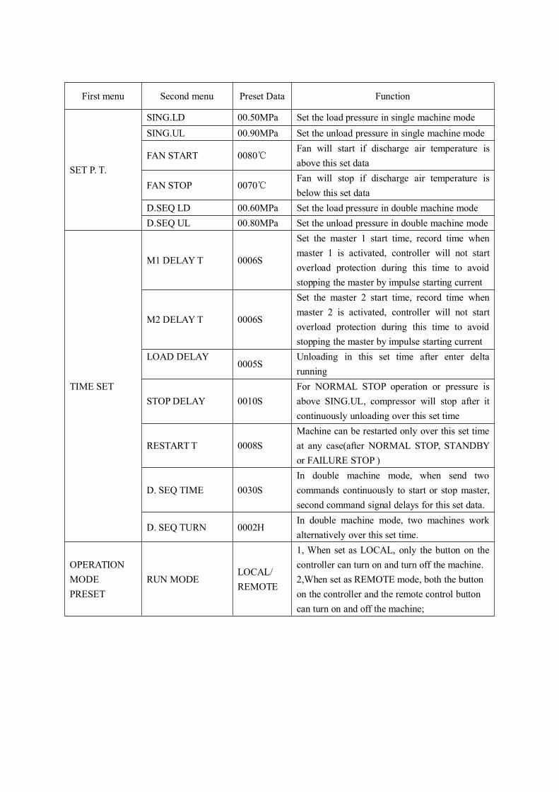
First menu Second menu Preset Data Function
SET P. T.
SING.LD 00.50MPa Set the load pressure in single machine modeSING.UL 00.90MPa Set the unload pressure in single machine mode
FAN START 0080℃Fan will start if discharge air temperature isabove this set data
FAN STOP 0070℃Fan will stop if discharge air temperature isbelow this set data
D.SEQ LD 00.60MPa Set the load pressure in double machine modeD.SEQ UL 00.80MPa Set the unload pressure in double machine mode
TIME SET
M1 DELAYT 0006S
Set the master 1 start time, record time whenmaster 1 is activated, controller will not startoverload protection during this time to avoidstopping the master by impulse starting current
M2 DELAYT 0006S
Set the master 2 start time, record time whenmaster 2 is activated, controller will not startoverload protection during this time to avoidstopping the master by impulse starting current
LOAD DELAY0005S
Unloading in this set time after enter deltarunning
STOPDELAY 0010SFor NORMAL STOP operation or pressure isabove SING.UL, compressor will stop after itcontinuously unloading over this set time
RESTARTT 0008SMachine can be restarted only over this set timeat any case(after NORMAL STOP, STANDBYor FAILURE STOP )
D. SEQ TIME 0030SIn double machine mode, when send twocommands continuously to start or stop master,second command signal delays for this set data.
D. SEQ TURN 0002HIn double machine mode, two machines workalternatively over this set time.
OPERATIONMODEPRESET
RUN MODELOCAL/REMOTE
1, When set as LOCAL, only the button on thecontroller can turn on and turn off the machine.2,When set as REMOTE mode, both the buttonon the controller and the remote control buttoncan turn on and off the machine;
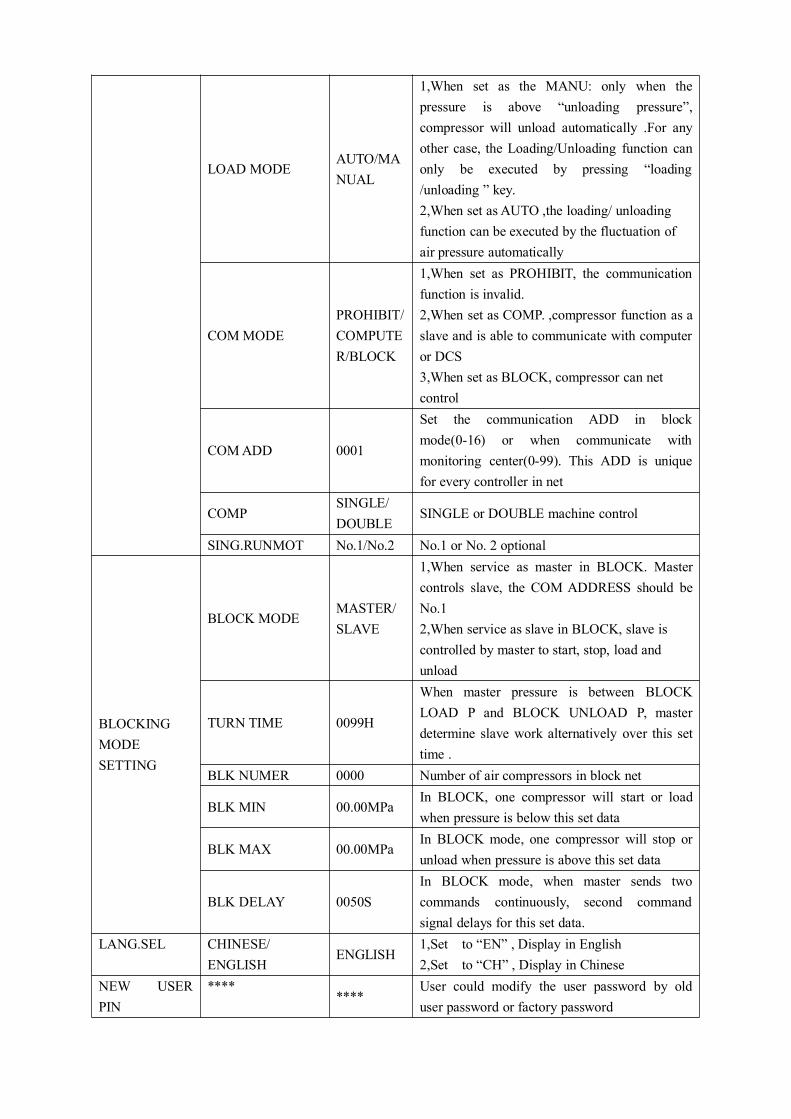
LOAD MODEAUTO/MANUAL
1,When set as the MANU: only when thepressure is above “unloading pressure”,compressor will unload automatically .For anyother case, the Loading/Unloading function canonly be executed by pressing “loading/unloading ” key.2,When set as AUTO ,the loading/ unloadingfunction can be executed by the fluctuation ofair pressure automatically
COMMODEPROHIBIT/COMPUTER/BLOCK
1,When set as PROHIBIT, the communicationfunction is invalid.2,When set as COMP. ,compressor function as aslave and is able to communicate with computeror DCS3,When set as BLOCK, compressor can netcontrol
COMADD 0001
Set the communication ADD in blockmode(0-16) or when communicate withmonitoring center(0-99). This ADD is uniquefor every controller in net
COMPSINGLE/DOUBLE
SINGLE or DOUBLE machine control
SING.RUNMOT No.1/No.2 No.1 or No. 2 optional
BLOCKINGMODESETTING
BLOCK MODEMASTER/SLAVE
1,When service as master in BLOCK. Mastercontrols slave, the COM ADDRESS should beNo.12,When service as slave in BLOCK, slave iscontrolled by master to start, stop, load andunload
TURN TIME 0099H
When master pressure is between BLOCKLOAD P and BLOCK UNLOAD P, masterdetermine slave work alternatively over this settime .
BLK NUMER 0000 Number of air compressors in block net
BLK MIN 00.00MPaIn BLOCK, one compressor will start or loadwhen pressure is below this set data
BLK MAX 00.00MPaIn BLOCK mode, one compressor will stop orunload when pressure is above this set data
BLK DELAY 0050SIn BLOCK mode, when master sends twocommands continuously, second commandsignal delays for this set data.
LANG.SEL CHINESE/ENGLISH
ENGLISH1,Set to “EN” , Display in English2,Set to “CH” , Display in Chinese
NEW USERPIN
********
User could modify the user password by olduser password or factory password
6、Factory Parameter View and Modification
FACTORY PARAMETER store relatively parameter set by factory. To check FACTORY PARAMETER, you
have to verify password first. In the first menu, press “ ” and “ ” to FACTORY PARAMETER, press
“ ”to switch to the menu below.
Input the correct password to switch to the FACTORYPARAMETER menu as below:
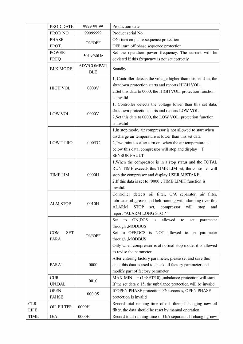
PARAMETER Initial Data Function
SYSTEMPARAMETER
MOTOR 1CUR
Maximum motoroverload data
/1.2
When the current of motor 1 is more than 1.2 times of theset data, the unit will stop for overload feature. (seetable2.1.1)
MOTOR 2CUR
Maximum motoroverload data
/1.2
When the current of motor 2 is more than 1.2 times of theset data, the unit will stop for overload feature.
ALARM T 1. 105℃When motor 1 discharge air temperature reaches this setdata, compressor will alarm
STOPT 1. 110℃When motor 1 discharge air temperature reaches this setdata, compressor will alarm and stop
STOP P. 1.00MPaWhen pressure reaches this set data ,compressor will alarmand stop
MAX U.L. 0.80MPaThis data is the maximum of UNLOADING P. TheUNLOADING P in the customer parameter must be set nohigher than this data.
MOT1 TIME 000000H Revise motor 1 run timeMOT2 TIME 000000H Revise motor 2 run time
CLR FAULT 0000Input the password 8888 and press “set “button to clear allthe history failure record.
ALARM T2. 105℃When motor 2 discharge air temperature reaches this setdata, compressor will alarm
STOPT 2. 110℃When motor 2 discharge air temperature reaches this setdata, compressor will alarm and stop
INPUT CODE****
SYSTEM PARAMETER
CLR LIFE TIME
MAX LIFE TIME
PROD DATE 9999-99-99 Production datePROD NO 99999999 Product serial No.PHASEPROT..
ON/OFFON: turn on phase sequence protectionOFF: turn off phase sequence protection
POWERFREQ
50Hz/60HzSet the operation power frequency. The current will bedeviated if this frequency is not set correctly
BLK MODEADV/COMPATI
BLEStandby
HIGH VOL. 0000V
1, Controller detects the voltage higher than this set data, theshutdown protection starts and reports HIGH VOL.2,Set this data to 0000, the HIGH VOL. protection functionis invalid
LOWVOL. 0000V
1, Controller detects the voltage lower than this set data,shutdown protection starts and reports LOWVOL.2,Set this data to 0000, the LOWVOL. protection functionis invalid
LOW T PRO -0005℃
1,In stop mode, air compressor is not allowed to start whendischarge air temperature is lower than this set data2,Two minutes after turn on, when the air temperature isbelow this data, compressor will stop and display TSENSOR FAULT
TIME LIM 0000H
1,When the compressor is in a stop status and the TOTALRUN TIME exceeds this TIME LIM set, the controller willstop the compressor and display USER MISTAKE;2,If this data is set to ‘0000’, TIME LIMIT function isinvalid.
ALM STOP 0010H
Controller detects oil filter, O/A separator, air filter,lubricate oil ,grease and belt running with alarming over thisALARM STOP set, compressor will stop andreport ”ALARM LONG STOP ”
COM SETPARA
ON/OFF
Set to ON,DCS is allowed to set parameterthrough ,MODBUSSet to OFF,DCS is NOT allowed to set parameterthrough ,MODBUSOnly when compressor is at normal stop mode, it is allowedto revise the parameter.
PARA1 0000After entering factory parameter, please set and save thisdata .this data is used to check all factory parameter andmodify part of factory parameter.
CURUN.BAL.
0010MAX-MIN = (1+SET/10) ,unbalance protection will startIf the set data ≥ 15, the unbalance protection will be invalid.
OPENPAHSE
000.0SIf OPEN PHASE protection ≥20 seconds, OPEN PHASEprotection is invalid
CLRLIFETIME
OIL FILTER 0000HRecord total running time of oil filter, if changing new oilfilter, the data should be reset by manual operation.
O/A 0000H Record total running time of O/A separator. If changing new
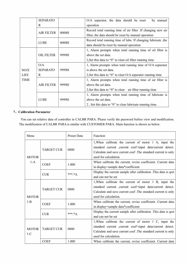
SEPARATOR
O/A separator, the data should be reset by manualoperation
AIR FILTER 0000HRecord total running time of air filter .If changing new airfilter, the data should be reset by manual operation
LUBE 0000HRecord total running time of lube. If changing lubricate ,thedata should be reset by manual operation
MAXLIFETIME
OIL FILTER 9999H1, Alarm prompts when total running time of oil filter isabove the set data.2,Set this data to “0” to clear oil filter running time
O/ASEPARATOR
9999H1, Alarm prompts when total running time of O/A separatoris above the set data.2,Set this data to “0” to clear O/A separator running time
AIR FILTER 9999H1, Alarm prompts when total running time of air filter isabove the set data.2,Set this data to “0” to clear air filter running time
LUBE 9999H1, Alarm prompts when total running time of lubricate isabove the set data.2 , Set this data to “0” to clear lubricate running time.
7、Calibration Parameter
You can set relative data of controller in CALBR PARA. Please verify the password before view and modification.The modification of CALBR PARA is similar with CUSTOMER PARA. Main function is shown as below.
Menu Preset Data Function
MOTOR1-A
TARGET CUR 0000
1,When calibrate the current of motor 1 A, input thestandard current ,current coef=input data/current detect.Calculate and save current coef .The standard current is onlyused for calculation.
COEF 1.000When calibrate the current, revise coefficient. Current datain display=sample data*coefficient
CUR ***.*ADisplay the current sample after calibration .This data is qretand can not be set
MOTOR1-B
TARGET CUR 0000
1,When calibrate the current of motor 1 B, input thestandard current ,current coef=input data/current detect.Calculate and save current coef .The standard current is onlyused for calculation.
COEF 1.000When calibrate the current, revise coefficient. Current datain display=sample data*coefficient
CUR ***.*ADisplay the current sample after calibration .This data is qretand can not be set
MOTOR1-C
TARGET CUR 0000
1,When calibrate the current of motor 1 C, input thestandard current ,current coef=input data/current detect.Calculate and save current coef .The standard current is onlyused for calculation.
COEF 1.000 When calibrate the current, revise coefficient. Current data
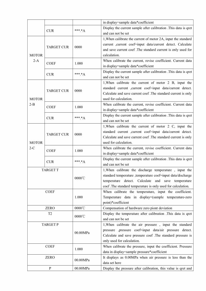
in display=sample data*coefficient
CUR ***.*ADisplay the current sample after calibration .This data is qretand can not be set
MOTOR2-A
TARGET CUR 0000
1,When calibrate the current of motor 2A, input the standardcurrent ,current coef=input data/current detect. Calculateand save current coef .The standard current is only used forcalculation.
COEF 1.000When calibrate the current, revise coefficient. Current datain display=sample data*coefficient
CUR ***.*ADisplay the current sample after calibration .This data is qretand can not be set
MOTOR2-B
TARGET CUR 0000
1,When calibrate the current of motor 2 B, input thestandard current ,current coef=input data/current detect.Calculate and save current coef .The standard current is onlyused for calculation.
COEF 1.000When calibrate the current, revise coefficient. Current datain display=sample data*coefficient
CUR ***.*ADisplay the current sample after calibration .This data is qretand can not be set
MOTOR2-C
TARGET CUR 0000
1,When calibrate the current of motor 2 C, input thestandard current ,current coef=input data/current detect.Calculate and save current coef .The standard current is onlyused for calculation.
COEF 1.000When calibrate the current, revise coefficient. Current datain display=sample data*coefficient
CUR ***.*ADisplay the current sample after calibration .This data is qretand can not be set
TARGETT
0000℃
1,When calibrate the discharge temperature , input thestandard temperature ,temperature coef=input data/dischargetemperature detect. Calculate and save temperaturecoef .The standard temperature is only used for calculation.
COEF1.000
When calibrate the temperature, input the coefficient.Temperature data in display=(sample temperature-zeropoint)*coefficient
ZERO 0000℃ Compensation of hardware zero piont deviationT2
0000℃Display the temperature after calibration .This data is qretand can not be set
TARGET P
00.00MPa
1,When calibrate the air pressure , input the standardpressure ,pressure coef=input data/air pressure detect.Calculate and save pressure coef .The standard pressure isonly used for calculation.
COEF1.000
When calibrate the pressure, input the coefficient. Pressuredata in display=sample pressure*coefficient
ZERO00.00MPa
It displays as 0.00MPa when air pressure is less than thedata set here
P 00.00MPa Display the pressure after calibration, this value is qret and
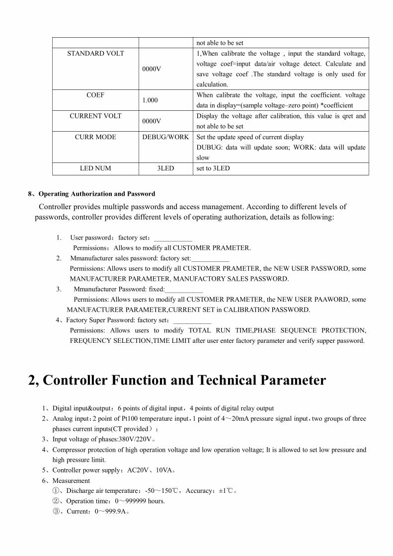
not able to be setSTANDARD VOLT
0000V
1,When calibrate the voltage , input the standard voltage,voltage coef=input data/air voltage detect. Calculate andsave voltage coef .The standard voltage is only used forcalculation.
COEF1.000
When calibrate the voltage, input the coefficient. voltagedata in display=(sample voltage–zero point) *coefficient
CURRENT VOLT0000V
Display the voltage after calibration, this value is qret andnot able to be set
CURR MODE DEBUG/WORK Set the update speed of current displayDUBUG: data will update soon; WORK: data will updateslow
LED NUM 3LED set to 3LED
8、Operating Authorization and Password
Controller provides multiple passwords and access management. According to different levels ofpasswords, controller provides different levels of operating authorization, details as following:
1. User password:factory set:___________Permissions:Allows to modify all CUSTOMER PRAMETER.
2. Mmanufacturer sales password: factory set:___________Permissions: Allows users to modify all CUSTOMER PRAMETER, the NEW USER PASSWORD, someMANUFACTURER PARAMETER, MANUFACTORY SALES PASSWORD.
3. Mmanufacturer Password: fixed:___________Permissions: Allows users to modify all CUSTOMER PRAMETER, the NEW USER PAAWORD, some
MANUFACTURER PARAMETER,CURRENT SET in CALIBRATION PASSWORD.4、Factory Super Password: factory set:___________
Permissions: Allows users to modify TOTAL RUN TIME,PHASE SEQUENCE PROTECTION,FREQUENCY SELECTION,TIME LIMIT after user enter factory parameter and verify supper password.
2, Controller Function and Technical Parameter
1、Digital input&output:6 points of digital input,4 points of digital relay output2、Analog input:2 point of Pt100 temperature input,1 point of 4~20mA pressure signal input,two groups of three
phases current inputs(CT provided);
3、Input voltage of phases:380V/220V。
4、Compressor protection of high operation voltage and low operation voltage; It is allowed to set low pressure andhigh pressure limit.
5、Controller power supply:AC20V、10VA。6、Measurement
①、Discharge air temperature:-50~150℃,Accuracy:±1℃。
②、Operation time:0~999999 hours.③、Current:0~999.9A。
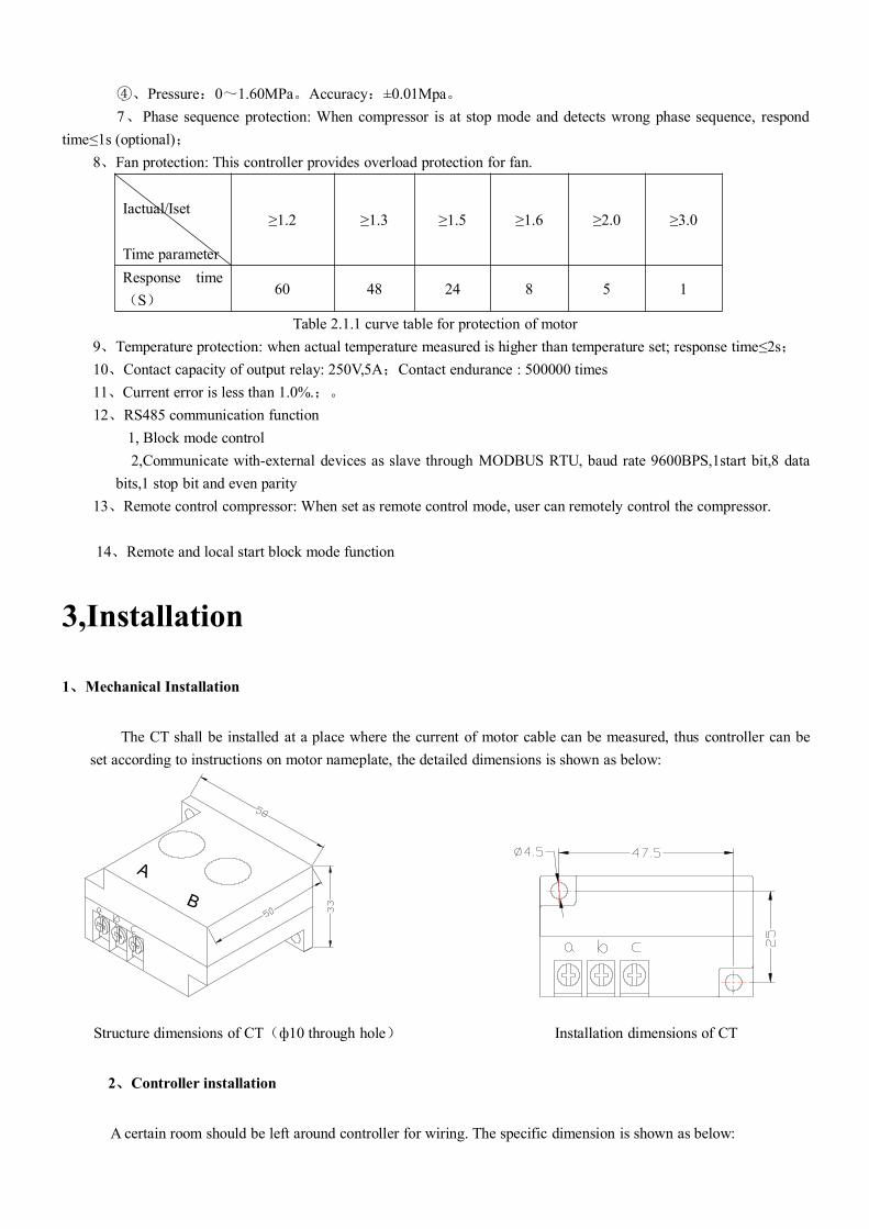
④、Pressure:0~1.60MPa。Accuracy:±0.01Mpa。7、Phase sequence protection: When compressor is at stop mode and detects wrong phase sequence, respond
time≤1s (optional);8、Fan protection: This controller provides overload protection for fan.
Iactual/Iset
Time parameter
≥1.2 ≥1.3 ≥1.5 ≥1.6 ≥2.0 ≥3.0
Response time(S)
60 48 24 8 5 1
Table 2.1.1 curve table for protection of motor9、Temperature protection: when actual temperature measured is higher than temperature set; response time≤2s;10、Contact capacity of output relay: 250V,5A;Contact endurance : 500000 times11、Current error is less than 1.0%.;。
12、RS485 communication function1, Block mode control2,Communicate with-external devices as slave through MODBUS RTU, baud rate 9600BPS,1start bit,8 data
bits,1 stop bit and even parity13、Remote control compressor: When set as remote control mode, user can remotely control the compressor.
14、Remote and local start block mode function
3,Installation
1、Mechanical Installation
The CT shall be installed at a place where the current of motor cable can be measured, thus controller can beset according to instructions on motor nameplate, the detailed dimensions is shown as below:
Structure dimensions of CT(ф10 through hole) Installation dimensions of CT
2、Controller installation
A certain room should be left around controller for wiring. The specific dimension is shown as below:
B
A
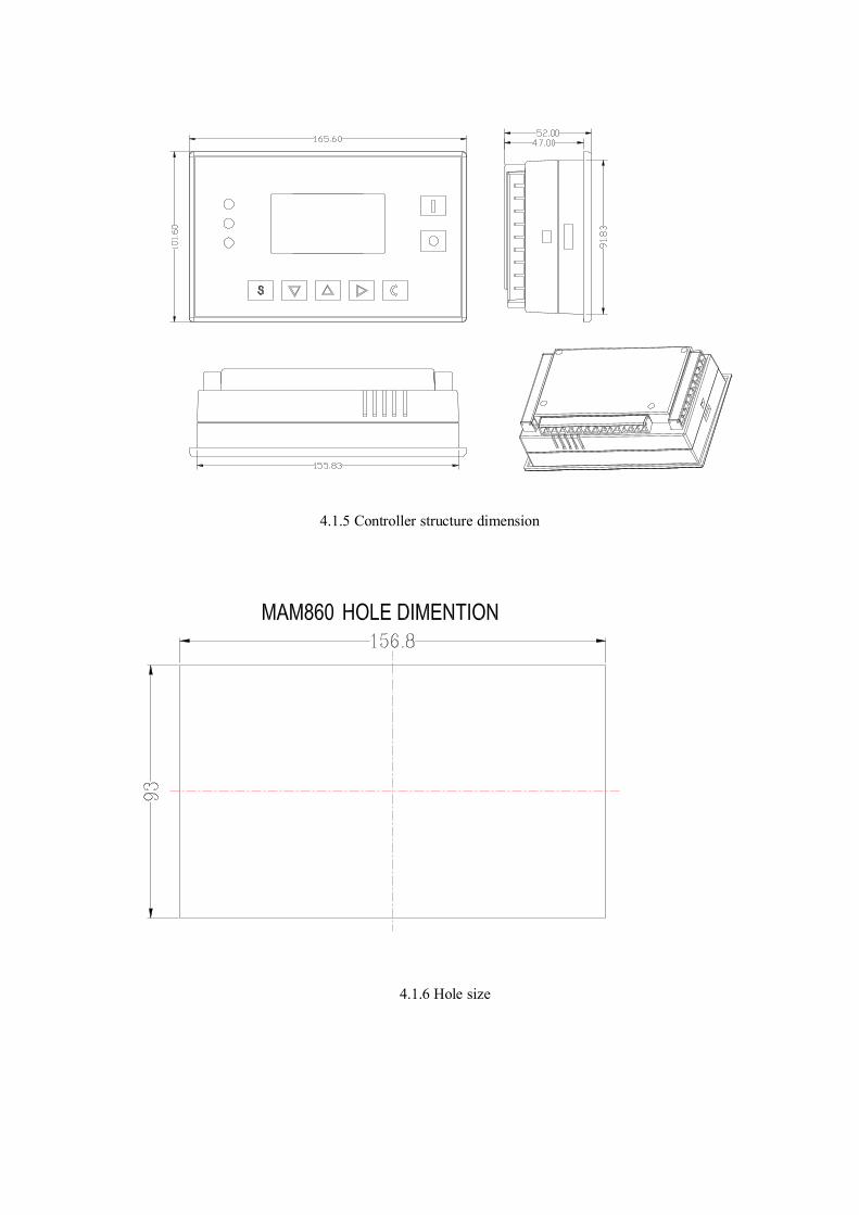
4.1.5 Controller structure dimension
4.1.6 Hole size
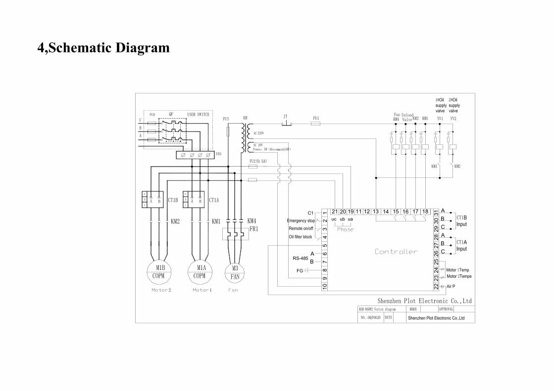
4,Schematic Diagram
1211
109
87
65
43
2
192021 3130
2928
2726
2524
2322
FG
1
ABRS-485
C1ub uauc
13 14 15 16 17 18
ABC
12
CBA


![User Guide...User. {{]}]} {}]}](https://img.pdfslide.net/doc/110x75/60918ca14327954d24291644/-user-guide-user-.jpg)

