Embed Size (px)
Citation preview
User manual
Porsche Diagnostics Tool PDT999
Document version 1.8
By P. Moers & T. Jenniskens
August 2011
TABLE OF CONTENTS
1. Introduction ...........................................................................................................................................4
2. How to use the PDT999? .....................................................................................................................7
2.1 Introduction: ...................................................................................................................................7
2.2 How to navigate through the menus: ............................................................................................8
2.3 Special command’s, screens, etc: .............................................................................................. 15
2.3.1 Select a menu item with a *: ................................................................................................... 15
2.3.2 Select a menu item when engine runs: .................................................................................. 16
2.3.3 Select a menu item when only ignition on: ............................................................................. 17
2.3.4 Connection error: .................................................................................................................... 17
3. Commands on the PDT999: .............................................................................................................. 18
3.1 Menu item “928” ......................................................................................................................... 18
3.1.1 Menu item “connect LH”: ........................................................................................................ 18
3.1.1.1 Input signals: ........................................................................................................ 19
3.1.1.2 drive links: ............................................................................................................ 20
3.1.1.3 actual values: ....................................................................................................... 21
3.1.2 Menu item “connect EZK”: ...................................................................................................... 23
3.1.2.1 Sensors: ............................................................................................................... 23
3.1.2.2 Actual values: ....................................................................................................... 24
3.1.3 Menu item “connect PSD”: ...................................................................................................... 25
3.1.3.1 Drive links: ........................................................................................................... 25
3.1.4 Menu item “connect RDK”: ..................................................................................................... 27
3.1.4.1 Trip information: ................................................................................................... 27
3.1.4.2 Input signals: ........................................................................................................ 27
3.1.4.3 Sensors: ............................................................................................................... 28
3.1.5 Menu item “connect ALARM”: ................................................................................................ 29
3.1.5.1 Input signals: ........................................................................................................ 29
3.1.5.2 Drive links: ........................................................................................................... 29
3.1.5.3 Coding “landcoding”: ............................................................................................ 30
3.1.6 Menu item “connect AIRBAG”: ............................................................................................... 31
3.1.6.1 “downtime”: .......................................................................................................... 31
3.1.6.2 “crash data”: ......................................................................................................... 31
3.1.7 Menu item “knock count”: ....................................................................................................... 32
3.1.8 Menu item “idle adaptation”: ................................................................................................... 33
3.1.9 Menu item “dashboard diagnosis”: ......................................................................................... 34
3.2 Menu item “944” ......................................................................................................................... 35
3.2.1 Menu item “connect Motronic”: ............................................................................................... 35
3.2.1.1 System adaptation: .............................................................................................. 35
3.2.1.2 Input signals: ........................................................................................................ 36
3.2.1.3 Drive links: ........................................................................................................... 37
3.2.1.4 Actual values: ....................................................................................................... 37
3.2.2 Menu item “connect ALARM”: ................................................................................................ 38
3.2.3 Menu item “connect AIRBAG”: ............................................................................................... 38
3.2.4 Menu item “knock count”: ....................................................................................................... 38
3.3 Menu item “964” ......................................................................................................................... 39
3.3.1 Menu item “connect Motronic”: ............................................................................................... 39
3.3.1.1 System adaptation: .............................................................................................. 39
3.3.1.2 Input signals: ........................................................................................................ 40
3.3.1.3 Drive links: ........................................................................................................... 40
3.3.1.4 Actual values: ....................................................................................................... 41
3.3.2 Menu item “connect ALARM”: ................................................................................................ 42
3.3.3 Menu item “connect AIRBAG”: ............................................................................................... 42
3.3.4 Menu item “connect CLIMATE”: ............................................................................................. 42
3.3.4.1 Input signals: ........................................................................................................ 42
3.3.4.2 Sensors: ............................................................................................................... 42
3.3.4.3 Drive links: ........................................................................................................... 43
3.3.4.4 Actual values: ....................................................................................................... 43
3.3.5 Menu item “connect PDAS”: ................................................................................................... 44
3.3.5.1 Input signals: ........................................................................................................ 44
3.3.5.2 Drive links: ........................................................................................................... 44
3.3.6 Menu item “connect TIPTRONIC”: ......................................................................................... 47
3.3.6.1 Input signals: ........................................................................................................ 47
3.3.6.2 Drive links: ........................................................................................................... 48
3.3.6.3 Actual values: ....................................................................................................... 48
3.3.6.4 Coding: ................................................................................................................. 49
3.4 Menu item “968” ......................................................................................................................... 50
3.4.1 Menu item “connect Motronic”: ............................................................................................... 50
3.4.1.1 Input signals: ........................................................................................................ 50
3.4.1.2 Drive links: ........................................................................................................... 51
3.4.1.3 Drive links active: ................................................................................................. 51
3.4.1.4 Actual values: ....................................................................................................... 51
3.4.2 Menu item “connect ALARM”: ................................................................................................ 52
3.4.3 Menu item “connect AIRBAG”: ............................................................................................... 52
3.4.4 Menu item “connect TIPTRONIC”: ......................................................................................... 52
3.5 Menu item “993” ......................................................................................................................... 53
3.5.1 Menu item “connect Motronic”: ............................................................................................... 53
3.5.1.1 Input signals: ........................................................................................................ 53
3.5.1.2 Drive links: ........................................................................................................... 54
3.5.1.3 Drive links active: ................................................................................................. 54
3.5.1.4 Actual values: ....................................................................................................... 55
3.5.2 Menu item “connect ALARM”: ................................................................................................ 55
3.5.3 Menu item “connect AIRBAG”: ............................................................................................... 55
3.5.4 Menu item “connect CLIMATE”: ............................................................................................. 55
3.5.5 Menu item “connect TIPTRONIC”: ......................................................................................... 55
3.5.6 Menu item “connect ABS”: ...................................................................................................... 56
3.5.6.1 Drive links: ........................................................................................................... 56
3.5.6.2 Actual values: ....................................................................................................... 58
3.5.6.3 Bleed: ................................................................................................................... 58
3.6 Menu item “settings” ................................................................................................................... 59
3.6.1 Version: ................................................................................................................................... 59
3.6.2 Supported ECU’s: ................................................................................................................... 59
3.6.3 Menu item “connect Diag ECU”: ............................................................................................. 61
3.6.3.1 Sensors: ............................................................................................................... 61
3.6.3.2 Drive links: ........................................................................................................... 62
3.6.3.3 Actual values: ....................................................................................................... 62
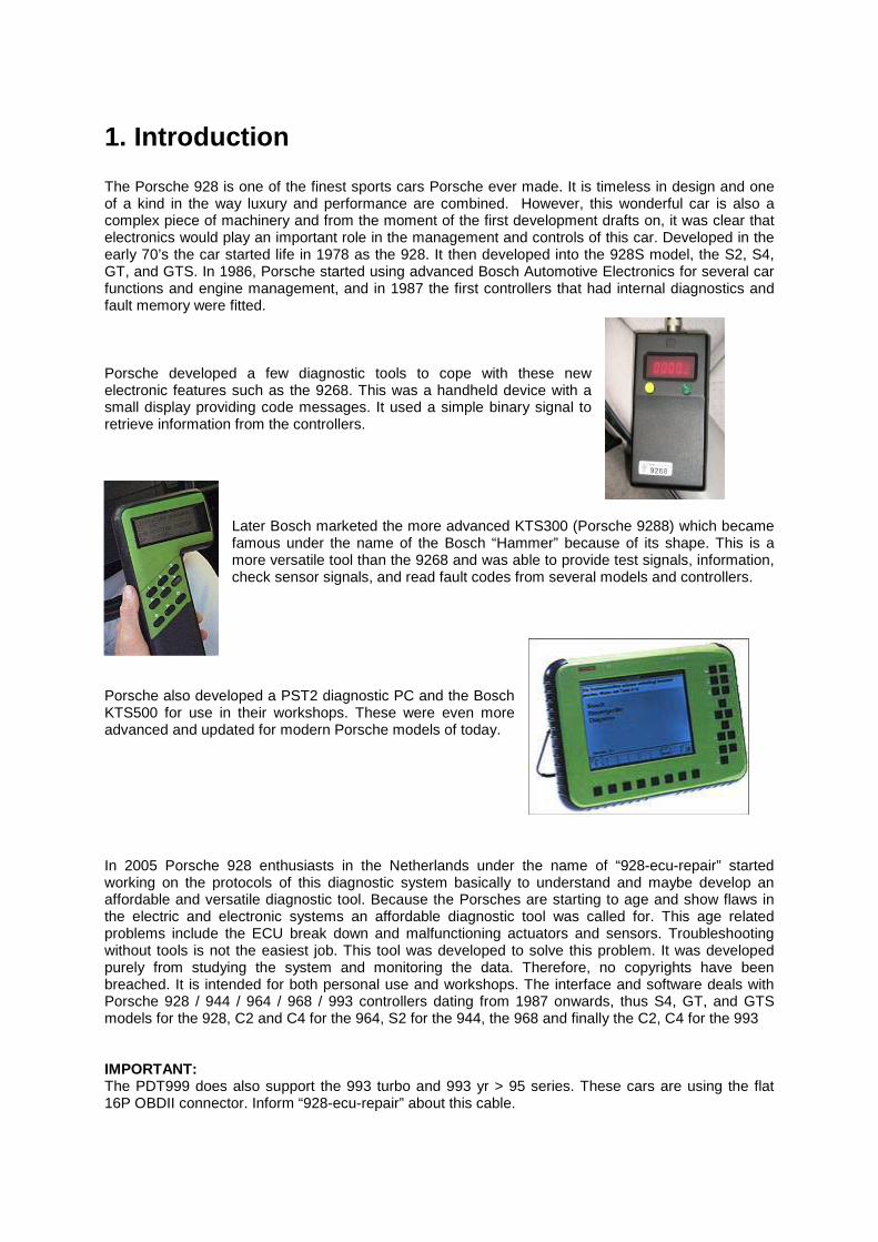
1. Introduction The Porsche 928 is one of the finest sports cars Porsche ever made. It is timeless in design and one of a kind in the way luxury and performance are combined. However, this wonderful car is also a complex piece of machinery and from the moment of the first development drafts on, it was clear that electronics would play an important role in the management and controls of this car. Developed in the early 70’s the car started life in 1978 as the 928. It then developed into the 928S model, the S2, S4, GT, and GTS. In 1986, Porsche started using advanced Bosch Automotive Electronics for several car functions and engine management, and in 1987 the first controllers that had internal diagnostics and fault memory were fitted. Porsche developed a few diagnostic tools to cope with these new electronic features such as the 9268. This was a handheld device with a small display providing code messages. It used a simple binary signal to retrieve information from the controllers.
Later Bosch marketed the more advanced KTS300 (Porsche 9288) which became famous under the name of the Bosch “Hammer” because of its shape. This is a more versatile tool than the 9268 and was able to provide test signals, information, check sensor signals, and read fault codes from several models and controllers.
Porsche also developed a PST2 diagnostic PC and the Bosch KTS500 for use in their workshops. These were even more advanced and updated for modern Porsche models of today. In 2005 Porsche 928 enthusiasts in the Netherlands under the name of “928-ecu-repair” started working on the protocols of this diagnostic system basically to understand and maybe develop an affordable and versatile diagnostic tool. Because the Porsches are starting to age and show flaws in the electric and electronic systems an affordable diagnostic tool was called for. This age related problems include the ECU break down and malfunctioning actuators and sensors. Troubleshooting without tools is not the easiest job. This tool was developed to solve this problem. It was developed purely from studying the system and monitoring the data. Therefore, no copyrights have been breached. It is intended for both personal use and workshops. The interface and software deals with Porsche 928 / 944 / 964 / 968 / 993 controllers dating from 1987 onwards, thus S4, GT, and GTS models for the 928, C2 and C4 for the 964, S2 for the 944, the 968 and finally the C2, C4 for the 993 IMPORTANT: The PDT999 does also support the 993 turbo and 993 yr > 95 series. These cars are using the flat 16P OBDII connector. Inform “928-ecu-repair” about this cable.
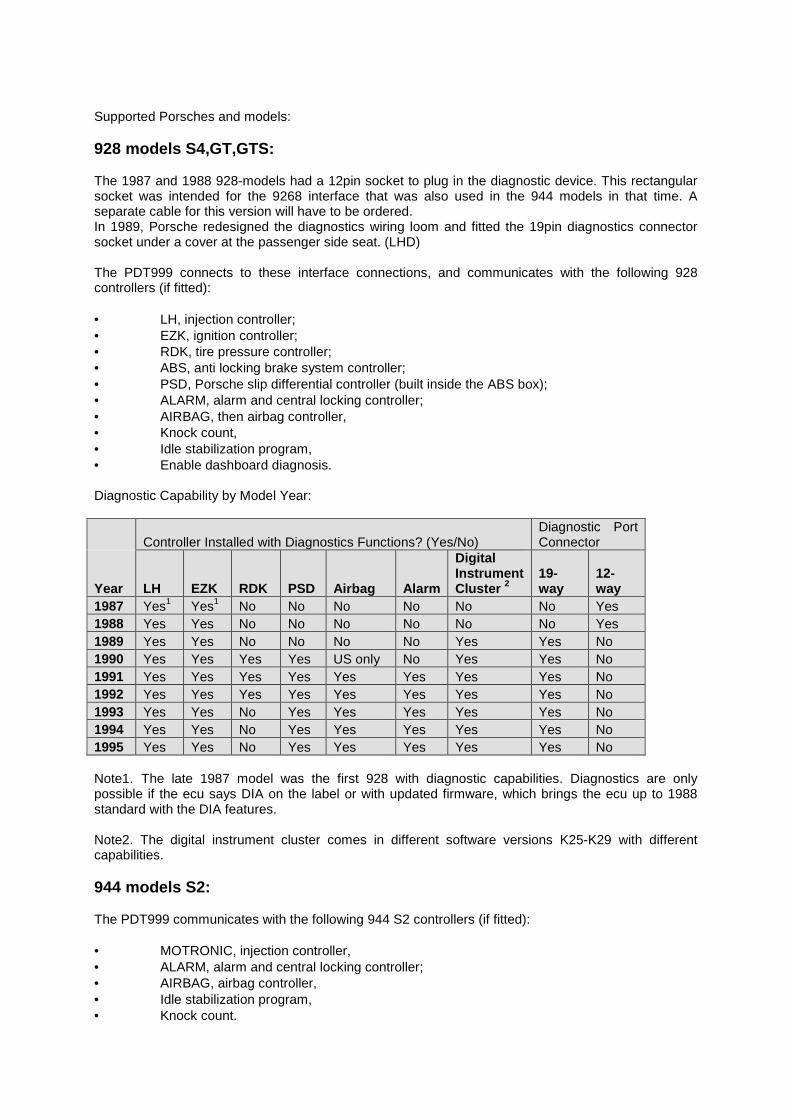
Supported Porsches and models: 928 models S4,GT,GTS: The 1987 and 1988 928-models had a 12pin socket to plug in the diagnostic device. This rectangular socket was intended for the 9268 interface that was also used in the 944 models in that time. A separate cable for this version will have to be ordered. In 1989, Porsche redesigned the diagnostics wiring loom and fitted the 19pin diagnostics connector socket under a cover at the passenger side seat. (LHD) The PDT999 connects to these interface connections, and communicates with the following 928 controllers (if fitted): • LH, injection controller; • EZK, ignition controller; • RDK, tire pressure controller; • ABS, anti locking brake system controller; • PSD, Porsche slip differential controller (built inside the ABS box); • ALARM, alarm and central locking controller; • AIRBAG, then airbag controller, • Knock count, • Idle stabilization program, • Enable dashboard diagnosis. Diagnostic Capability by Model Year:
Controller Installed with Diagnostics Functions? (Yes/No) Diagnostic Port Connector
Year LH EZK RDK PSD Airbag Alarm
Digital Instrument Cluster 2
19-way
12-way
1987 Yes1 Yes1 No No No No No No Yes 1988 Yes Yes No No No No No No Yes 1989 Yes Yes No No No No Yes Yes No 1990 Yes Yes Yes Yes US only No Yes Yes No 1991 Yes Yes Yes Yes Yes Yes Yes Yes No 1992 Yes Yes Yes Yes Yes Yes Yes Yes No 1993 Yes Yes No Yes Yes Yes Yes Yes No 1994 Yes Yes No Yes Yes Yes Yes Yes No 1995 Yes Yes No Yes Yes Yes Yes Yes No Note1. The late 1987 model was the first 928 with diagnostic capabilities. Diagnostics are only possible if the ecu says DIA on the label or with updated firmware, which brings the ecu up to 1988 standard with the DIA features. Note2. The digital instrument cluster comes in different software versions K25-K29 with different capabilities. 944 models S2: The PDT999 communicates with the following 944 S2 controllers (if fitted): • MOTRONIC, injection controller, • ALARM, alarm and central locking controller; • AIRBAG, airbag controller, • Idle stabilization program, • Knock count.
964 models C2 and C4: The round diagnose plug for the C2 and C4 models is fitted on the right site of the passenger’s foot well. The PDT999 communicates with the following 964 controllers (if fitted): • MOTRONIC, injection controller, • ALARM, alarm and central locking controller; • AIRBAG, then airbag controller, • CLIMATE, climate controller, • PDAS, Porsche Dynamische Allrad Steurung, porsche slip differential controller and anti system controller (only valid for C4 models), • TIPTRONIC, tiptronic controller (if fitted), • Idle stabilization program. 968: The PDT999 communicates with the following 968 controllers (if fitted): • MOTRONIC, injection controller, • ALARM, alarm and central locking controller; • AIRBAG, airbag controller, • TIPTRONIC, tiptronic controller (if fitted), 993 models C2, C4: The diagnose plug for the C2 and C4 models is fitted on the right site of the passengers foot well. The PDT999 communicates with the following 993 controllers (if fitted): • MOTRONIC, injection controller, • ABS, anti locking brake system controller, • ALARM, alarm and central locking controller; • AIRBAG, airbag controller, • TIPTRONIC, tiptronic controller (if fitted), • CLIMATE, climate controller. This document describes the all commands used in the PDT999. Commands like
• Reading ECU type, • Reading and clearing fault-codes, • Reading input signals like throttles, switches, etc • Reading actual values like temperatures, voltages, etc. • Reading sensor values like load, engine temperatures, etc, • Performing drive links like actuate injectors, flaps, blowers etc, • Performing drive links active when engine runs, • Performing idle stab programs, knock counts, enable dash diagnosis.
Most of the commands are also described in the Workshop Manuals of each car. So please refer to these manuals for additional information about the commands and results. The PDT reacts in such a way that the commands and responses are almost the same as the hammer KTS301 with a software module from august-95. But some commands are not implemented due to safety reasons. Commands like locking airbags. Once you lock an airbag, according to the workshop manual, it is not easy to unlock the airbag. “928-ecu-repair” does not like such kind of commands so left them out of the menu structure.
2. How to use the PDT999? This chapter describes in a nutshell how to use the tool.
2.1 Introduction:
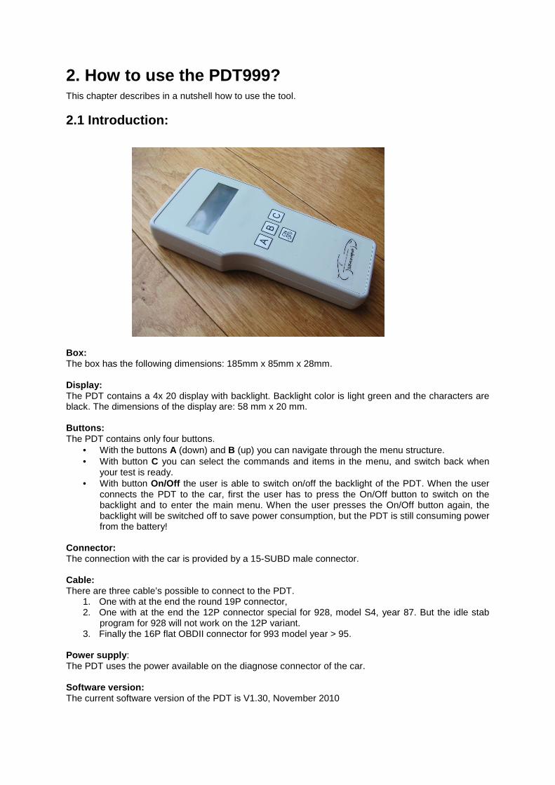
Box: The box has the following dimensions: 185mm x 85mm x 28mm. Display: The PDT contains a 4x 20 display with backlight. Backlight color is light green and the characters are black. The dimensions of the display are: 58 mm x 20 mm. Buttons: The PDT contains only four buttons.
• With the buttons A (down) and B (up) you can navigate through the menu structure. • With button C you can select the commands and items in the menu, and switch back when
your test is ready. • With button On/Off the user is able to switch on/off the backlight of the PDT. When the user
connects the PDT to the car, first the user has to press the On/Off button to switch on the backlight and to enter the main menu. When the user presses the On/Off button again, the backlight will be switched off to save power consumption, but the PDT is still consuming power from the battery!
Connector: The connection with the car is provided by a 15-SUBD male connector. Cable: There are three cable’s possible to connect to the PDT.
1. One with at the end the round 19P connector, 2. One with at the end the 12P connector special for 928, model S4, year 87. But the idle stab
program for 928 will not work on the 12P variant. 3. Finally the 16P flat OBDII connector for 993 model year > 95.
Power supply : The PDT uses the power available on the diagnose connector of the car. Software version: The current software version of the PDT is V1.30, November 2010
2.2 How to navigate through the menus: This paragraph describes the part of the complete menu structure. part of the total menu structure because the other part of the menu structure (commands of each ECU) of will be explained in Chapter 3. This paragraph shows a motronic example: how to connect to the motronic, how to navigate through the motronic menus, how to read the fault-codes, how to clear them, how to select a certain test, how to use the buttons, etc. Let’s start:
Connect the PDT to the car and press the Onoff butt on
-------------------- PDT999 PDT999 PDT999 PDT999 -------------------- 928/944/964/968/993928/944/964/968/993928/944/964/968/993928/944/964/968/993 (c) 928(c) 928(c) 928(c) 928----ecuecuecuecu----repair repair repair repair V1.30 November 2010V1.30 November 2010V1.30 November 2010V1.30 November 2010
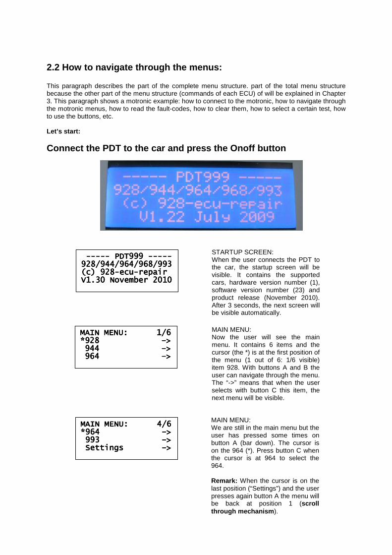
STARTUP SCREEN: When the user connects the PDT to the car, the startup screen will be visible. It contains the supported cars, hardware version number (1), software version number (23) and product release (November 2010). After 3 seconds, the next screen will be visible automatically.
MAIN MENU: 1/6MAIN MENU: 1/6MAIN MENU: 1/6MAIN MENU: 1/6 *928 *928 *928 *928 ––––>>>> 944 944 944 944 ––––>>>> 964 964 964 964 ––––>>>>
MAIN MENU: Now the user will see the main menu. It contains 6 items and the cursor (the *) is at the first position of the menu (1 out of 6: 1/6 visible) item 928. With buttons A and B the user can navigate through the menu. The “->” means that when the user selects with button C this item, the next menu will be visible.
MAIN MENU: 4/6MAIN MENU: 4/6MAIN MENU: 4/6MAIN MENU: 4/6 *964 *964 *964 *964 ––––>>>> 993 993 993 993 ––––>>>> Settings Settings Settings Settings ––––>>>>
MAIN MENU: We are still in the main menu but the user has pressed some times on button A (bar down). The cursor is on the 964 (*). Press button C when the cursor is at 964 to select the 964. Remark: When the cursor is on the last position (“Settings”) and the user presses again button A the menu will be back at position 1 (scroll through mechanism ).
964: 1/7964: 1/7964: 1/7964: 1/7 *MOTRONIC *MOTRONIC *MOTRONIC *MOTRONIC ––––>>>> ALARM ALARM ALARM ALARM ––––>>>> AIRBAG AIRBAG AIRBAG AIRBAG ––––>>>>
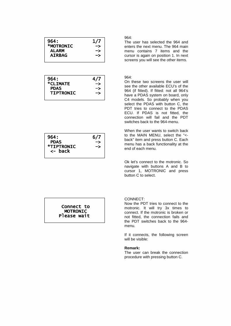
964: The user has selected the 964 and enters the next menu. The 964 main menu contains 7 items and the cursor is again on position 1. In next screens you will see the other items.
964: 4/7964: 4/7964: 4/7964: 4/7 *CLIMATE *CLIMATE *CLIMATE *CLIMATE ––––>>>> PDAS PDAS PDAS PDAS ––––>>>> TIPTRONIC TIPTRONIC TIPTRONIC TIPTRONIC ––––>>>>
964: On these two screens the user will see the other available ECU’s of the 964 (if fitted). If fitted: not all 964’s have a PDAS system on board, only C4 models. So probably when you select the PDAS with button C, the PDT tries to connect to the PDAS ECU. If PDAS is not fitted, the connection will fail and the PDT switches back to the 964-menu. When the user wants to switch back to the MAIN MENU, select the “<- back” item and press button C. Each menu has a back functionality at the end of each menu. Ok let’s connect to the motronic. So navigate with buttons A and B to cursor 1, MOTRONIC and press button C to select.
Connect to Connect to Connect to Connect to MOTRONIC MOTRONIC MOTRONIC MOTRONIC Please wait Please wait Please wait Please wait
CONNECT: Now the PDT tries to connect to the motronic. It will try 3x times to connect. If the motronic is broken or not fitted, the connection fails and the PDT switches back to the 964-menu. If it connects, the following screen will be visible: Remark: The user can break the connection procedure with pressing button C.
964: 6/7964: 6/7964: 6/7964: 6/7 PDAS PDAS PDAS PDAS ––––>>>> *TIPTRONIC *TIPTRONIC *TIPTRONIC *TIPTRONIC ––––>>>> <<<<---- backbackbackback

MOTRONIC 1/7*MOTRONIC 1/7*MOTRONIC 1/7*MOTRONIC 1/7* *read version *read version *read version *read version read fault codes read fault codes read fault codes read fault codes clear fault codes clear fault codes clear fault codes clear fault codes
MOTRONIC: So now the PDT is connected to the motronic. You can see that on the first line, right site. The “*” on this line is blinking. That means that the PDT is communicating with the motronic. When you see a “#” is blinking, that means that the engine of the car is running. Again a list with commands is available. With scroll down the user can see the other items (“input signals” etc). Remark: The first three menu items “read version”, “read fault codes” and “clear fault codes” are for all ECU’s the same. The cursor is at the first position but there is no “->” on the line at the right site. That means when the user selects this item, the user will NOT enter a menu anymore but enters an information screen with the requested information. The user selects item “read version”, press button C and the following information screen appears:
MOTRONIC 4/7*MOTRONIC 4/7*MOTRONIC 4/7*MOTRONIC 4/7* *input signals *input signals *input signals *input signals ––––>>>> drive links drive links drive links drive links ––––>>>> actual values actual values actual values actual values ––––>>>>
ECUECUECUECU----nr: M00MOTRONICnr: M00MOTRONICnr: M00MOTRONICnr: M00MOTRONIC Info1: 9646181240Info1: 9646181240Info1: 9646181240Info1: 9646181240 Info2: 0261200473Info2: 0261200473Info2: 0261200473Info2: 0261200473 Info3: 1267356577Info3: 1267356577Info3: 1267356577Info3: 1267356577
INFO: Now the user will see some information retrieved from the motronic. The version of the motronic is M00, which is the motronic version of the 964. The 968 has another motronic version, M03 and the 993 has motronic version M04. When the user presses button C again, the motronic main menu will be visible again. Ok, press button C to switch back to the motronic menu and press buttons A and B to navigate to the next item: “read fault codes”. Press button C to select the item “read fault codes”. Now the PDT reads the fault codes, that takes some time (5 seconds) and then the following information screen appears:
MOTRONIC 2/7*MOTRONIC 2/7*MOTRONIC 2/7*MOTRONIC 2/7* read version read version read version read version *read fault codes *read fault codes *read fault codes *read fault codes clear fault codes clear fault codes clear fault codes clear fault codes
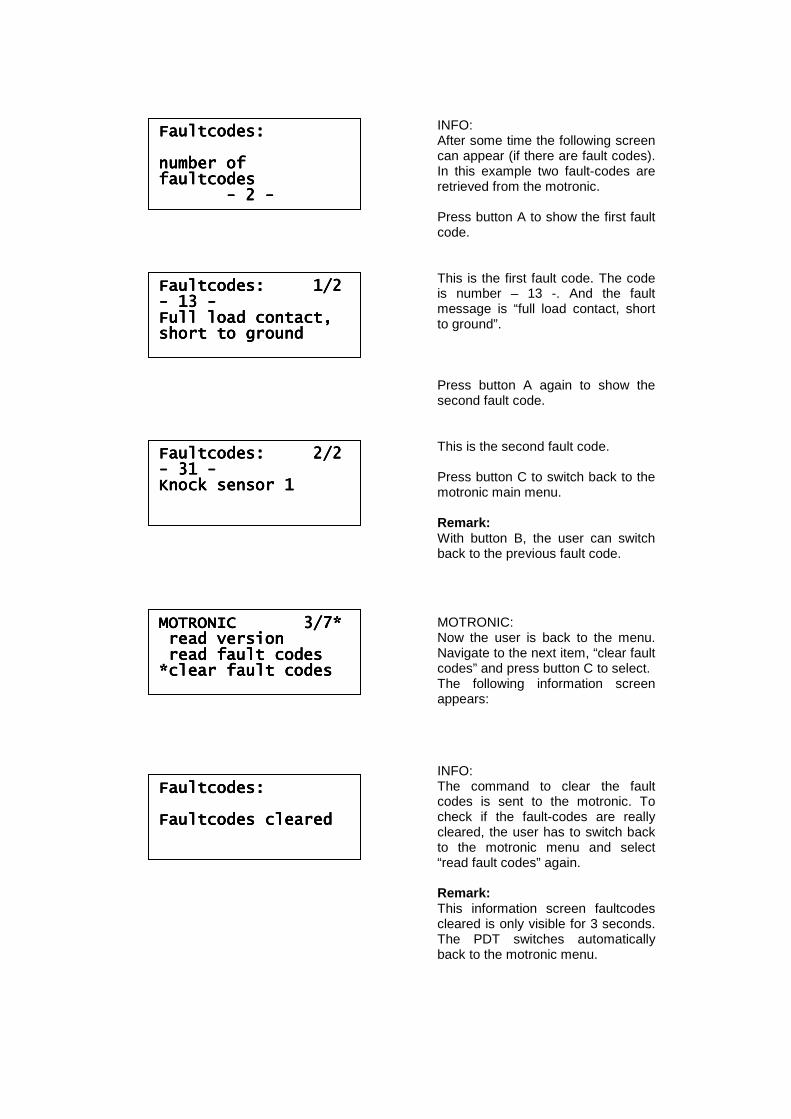
Faultcodes:Faultcodes:Faultcodes:Faultcodes: number of number of number of number of faultcodesfaultcodesfaultcodesfaultcodes ---- 2 2 2 2 ----
INFO: After some time the following screen can appear (if there are fault codes). In this example two fault-codes are retrieved from the motronic. Press button A to show the first fault code. This is the first fault code. The code is number – 13 -. And the fault message is “full load contact, short to ground”. Press button A again to show the second fault code. This is the second fault code. Press button C to switch back to the motronic main menu. Remark: With button B, the user can switch back to the previous fault code.
FaultcoFaultcoFaultcoFaultcodes: 1/2des: 1/2des: 1/2des: 1/2 ---- 13 13 13 13 ---- Full load contact,Full load contact,Full load contact,Full load contact, short to groundshort to groundshort to groundshort to ground
Faultcodes: 2/2Faultcodes: 2/2Faultcodes: 2/2Faultcodes: 2/2 ---- 31 31 31 31 ---- Knock sensor 1Knock sensor 1Knock sensor 1Knock sensor 1
MOTRONIC 3/7*MOTRONIC 3/7*MOTRONIC 3/7*MOTRONIC 3/7* read version read version read version read version read fault codes read fault codes read fault codes read fault codes *clear fault codes *clear fault codes *clear fault codes *clear fault codes
MOTRONIC: Now the user is back to the menu. Navigate to the next item, “clear fault codes” and press button C to select. The following information screen appears:
Faultcodes:Faultcodes:Faultcodes:Faultcodes: Faultcodes clearedFaultcodes clearedFaultcodes clearedFaultcodes cleared
INFO: The command to clear the fault codes is sent to the motronic. To check if the fault-codes are really cleared, the user has to switch back to the motronic menu and select “read fault codes” again. Remark: This information screen faultcodes cleared is only visible for 3 seconds. The PDT switches automatically back to the motronic menu.
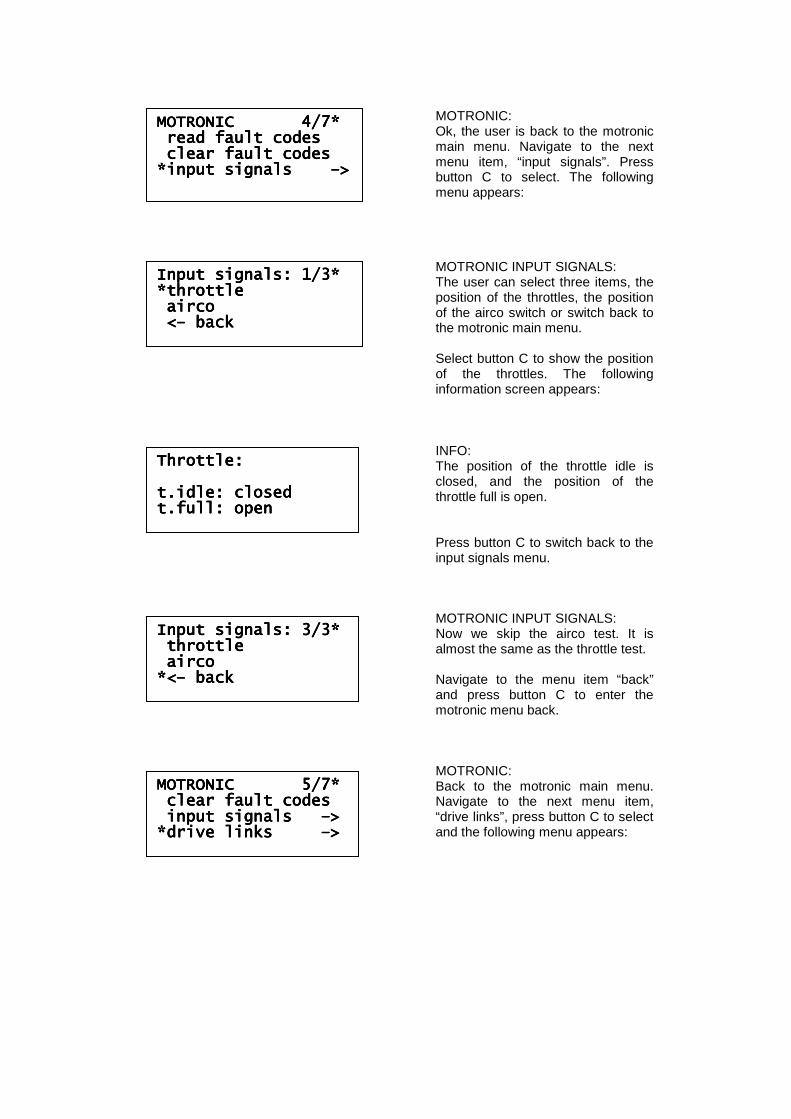
MOTRONIC 4/7*MOTRONIC 4/7*MOTRONIC 4/7*MOTRONIC 4/7* read fault codes read fault codes read fault codes read fault codes clear fault codes clear fault codes clear fault codes clear fault codes *input signals *input signals *input signals *input signals ––––>>>>
MOTRONIC: Ok, the user is back to the motronic main menu. Navigate to the next menu item, “input signals”. Press button C to select. The following menu appears:
Input signals: 1/3*Input signals: 1/3*Input signals: 1/3*Input signals: 1/3* *throttle*throttle*throttle*throttle aircoaircoaircoairco <<<<–––– backbackbackback
MOTRONIC INPUT SIGNALS: The user can select three items, the position of the throttles, the position of the airco switch or switch back to the motronic main menu. Select button C to show the position of the throttles. The following information screen appears:
Throttle:Throttle:Throttle:Throttle: t.idle: closedt.idle: closedt.idle: closedt.idle: closed t.full: opent.full: opent.full: opent.full: open
INFO: The position of the throttle idle is closed, and the position of the throttle full is open. Press button C to switch back to the input signals menu.
Input signals: 3/3*Input signals: 3/3*Input signals: 3/3*Input signals: 3/3* throttlethrottlethrottlethrottle aircoaircoaircoairco *<*<*<*<–––– backbackbackback
MOTRONIC INPUT SIGNALS: Now we skip the airco test. It is almost the same as the throttle test. Navigate to the menu item “back” and press button C to enter the motronic menu back.
MOTRONIC 5/7*MOTRONIC 5/7*MOTRONIC 5/7*MOTRONIC 5/7* clear fault codesclear fault codesclear fault codesclear fault codes input signals input signals input signals input signals ––––>>>> *drive links *drive links *drive links *drive links ––––>>>>
MOTRONIC: Back to the motronic main menu. Navigate to the next menu item, “drive links”, press button C to select and the following menu appears:
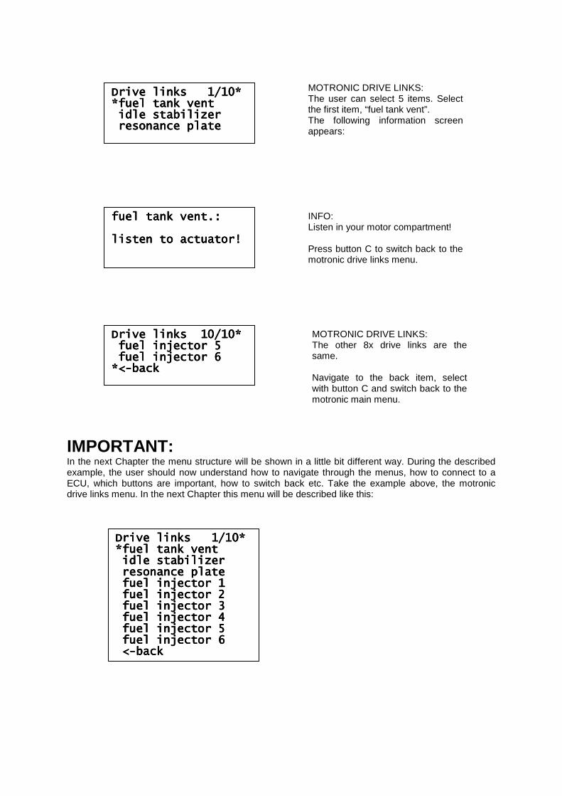
IMPORTANT: In the next Chapter the menu structure will be shown in a little bit different way. During the described example, the user should now understand how to navigate through the menus, how to connect to a ECU, which buttons are important, how to switch back etc. Take the example above, the motronic drive links menu. In the next Chapter this menu will be described like this:
Drive links 1/10*Drive links 1/10*Drive links 1/10*Drive links 1/10* *fuel tank vent*fuel tank vent*fuel tank vent*fuel tank vent idle stabilizeridle stabilizeridle stabilizeridle stabilizer resonance plateresonance plateresonance plateresonance plate
Drive links 10/10*Drive links 10/10*Drive links 10/10*Drive links 10/10* fuel injector 5fuel injector 5fuel injector 5fuel injector 5 fuel injector 6fuel injector 6fuel injector 6fuel injector 6 *<*<*<*<----backbackbackback
MOTRONIC DRIVE LINKS: The user can select 5 items. Select the first item, “fuel tank vent”. The following information screen appears:
fuel tank vent.:fuel tank vent.:fuel tank vent.:fuel tank vent.: listen to actuator!listen to actuator!listen to actuator!listen to actuator!
INFO: Listen in your motor compartment! Press button C to switch back to the motronic drive links menu.
MOTRONIC DRIVE LINKS: The other 8x drive links are the same. Navigate to the back item, select with button C and switch back to the motronic main menu.
Drive links 1/10*Drive links 1/10*Drive links 1/10*Drive links 1/10* *fuel *fuel *fuel *fuel tank venttank venttank venttank vent idle stabilizeridle stabilizeridle stabilizeridle stabilizer resonance plateresonance plateresonance plateresonance plate fuel injector 1fuel injector 1fuel injector 1fuel injector 1 fuel injector 2fuel injector 2fuel injector 2fuel injector 2 fuel injector 3fuel injector 3fuel injector 3fuel injector 3 fuel injector 4fuel injector 4fuel injector 4fuel injector 4 fuel injector 5fuel injector 5fuel injector 5fuel injector 5 fuel injector 6fuel injector 6fuel injector 6fuel injector 6 <<<<----backbackbackback
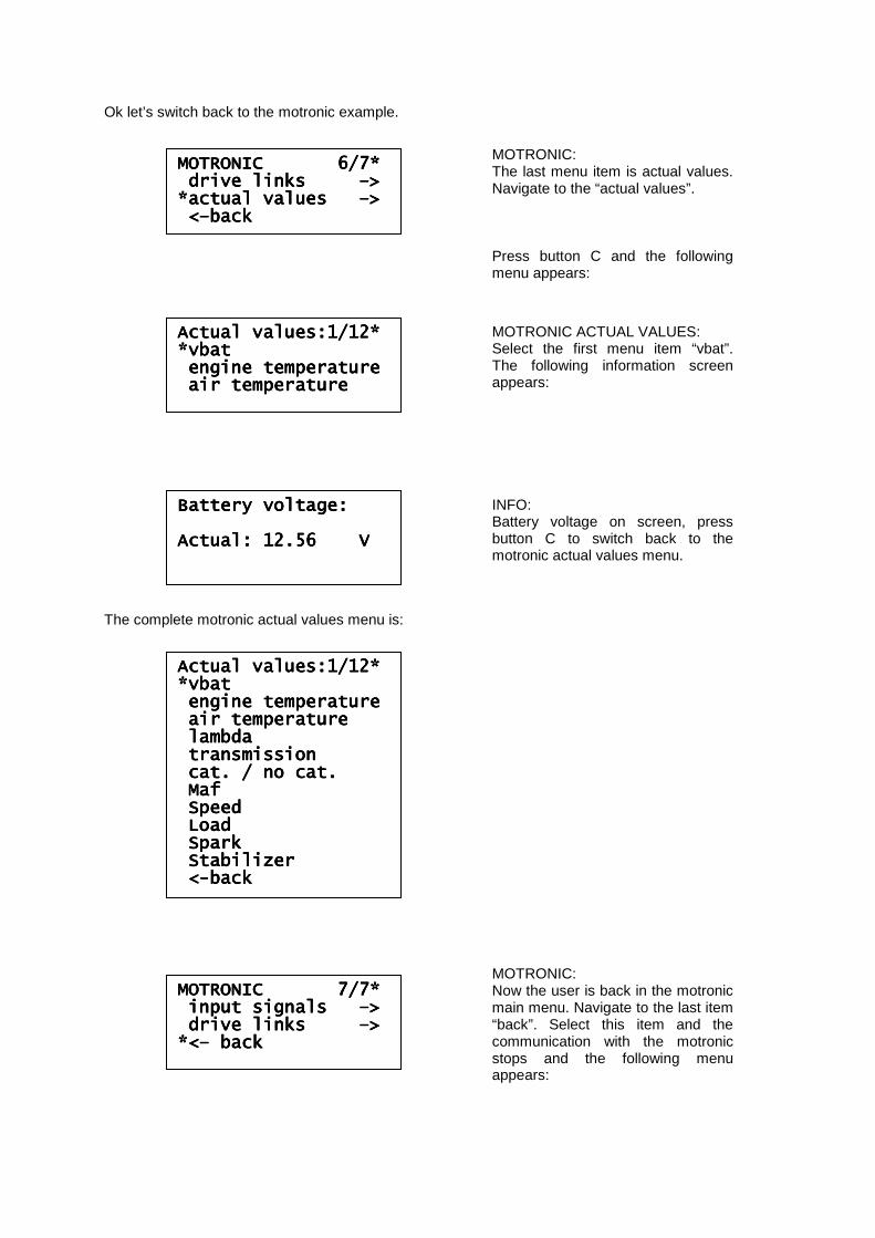
Ok let’s switch back to the motronic example. The complete motronic actual values menu is:
MOTRONIC 6/7*MOTRONIC 6/7*MOTRONIC 6/7*MOTRONIC 6/7* drive links drive links drive links drive links ––––>>>> *actual values *actual values *actual values *actual values ––––>>>> <<<<––––backbackbackback
MOTRONIC: The last menu item is actual values. Navigate to the “actual values”. Press button C and the following menu appears:
Actual values:1/12*Actual values:1/12*Actual values:1/12*Actual values:1/12* *vbat*vbat*vbat*vbat engine temperatureengine temperatureengine temperatureengine temperature air temperatureair temperatureair temperatureair temperature
Actual values:1/12*Actual values:1/12*Actual values:1/12*Actual values:1/12* *vbat*vbat*vbat*vbat engine temperatureengine temperatureengine temperatureengine temperature air temperatureair temperatureair temperatureair temperature lambdalambdalambdalambda transmissiontransmissiontransmissiontransmission cat. / no cat.cat. / no cat.cat. / no cat.cat. / no cat. MafMafMafMaf SpeedSpeedSpeedSpeed LoadLoadLoadLoad SparkSparkSparkSpark StabilizerStabilizerStabilizerStabilizer <<<<----backbackbackback
MOTRONIC ACTUAL VALUES: Select the first menu item “vbat”. The following information screen appears:
Battery voltage:Battery voltage:Battery voltage:Battery voltage: Actual: 12.56 VActual: 12.56 VActual: 12.56 VActual: 12.56 V
INFO: Battery voltage on screen, press button C to switch back to the motronic actual values menu.
MOTRONIC 7/7*MOTRONIC 7/7*MOTRONIC 7/7*MOTRONIC 7/7* input signals input signals input signals input signals ––––>>>> drive links drive links drive links drive links ––––>>>> *<*<*<*<–––– backbackbackback
MOTRONIC: Now the user is back in the motronic main menu. Navigate to the last item “back”. Select this item and the communication with the motronic stops and the following menu appears:
2.3 Special command’s, screens, etc: In the previous paragraph we explained the basics of the PDT. This paragraph describes the special commands, strange screen information and some explanation:
2.3.1 Select a menu item with a *: Main menu:
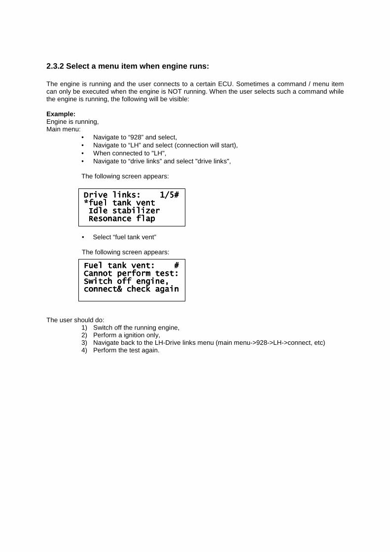
• Navigate to “964” and select, • Navigate to “climate” and select (connection will start), • When connected: Navigate to “input signals” and select "input signals", • Navigate to “airco switch” and select "airco switch",
The following screen appears:
On fourth line of the display, you see an additional star behind “airco switch” (red circle). What does this star mean? There are two versions of climate control ECU’s for the 964. The first version is version H03 and the second version is H04. This information the user can retrieve from the climate control ECU by reading the “read version” in the climate main menu. See the motronic example in paragraph 2.2 how to do. The airco switch is NOT available in climate version H03. So when the car has such a module inserted and the user wants to read the airco switch (which is not in) by selecting this menu item in PDT, the following screen appears:
Press button C to return to the climate input signals menu.
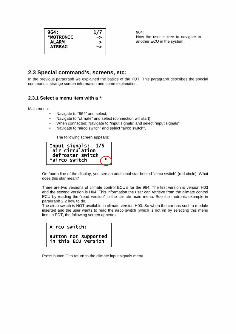
964: 1/7964: 1/7964: 1/7964: 1/7 *MOTRONIC *MOTRONIC *MOTRONIC *MOTRONIC ––––>>>> ALARM ALARM ALARM ALARM ––––>>>> AIRBAG AIRBAG AIRBAG AIRBAG ––––>>>>
964: Now the user is free to navigate to another ECU in the system.
Input signals: 1/5 Input signals: 1/5 Input signals: 1/5 Input signals: 1/5 air circulationair circulationair circulationair circulation defroster switchdefroster switchdefroster switchdefroster switch *airco switch **airco switch **airco switch **airco switch *
Airco switch:Airco switch:Airco switch:Airco switch: Button not supportedButton not supportedButton not supportedButton not supported in this ECU versionin this ECU versionin this ECU versionin this ECU version
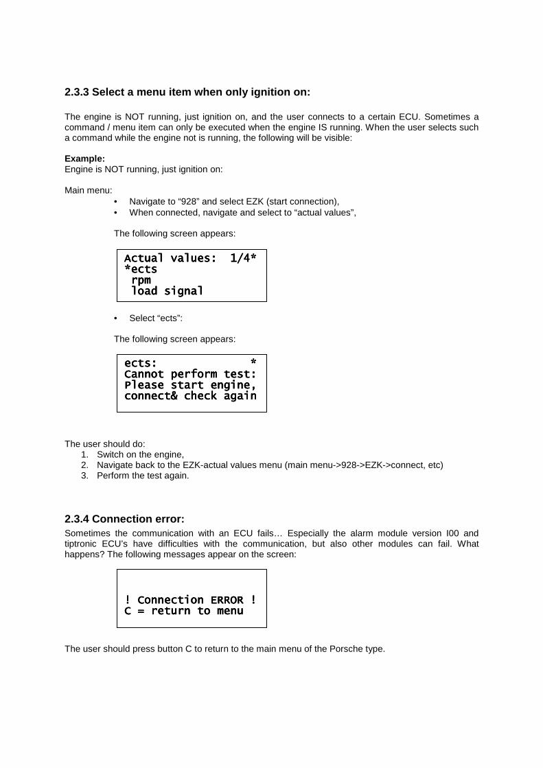
2.3.2 Select a menu item when engine runs: The engine is running and the user connects to a certain ECU. Sometimes a command / menu item can only be executed when the engine is NOT running. When the user selects such a command while the engine is running, the following will be visible: Example: Engine is running, Main menu:
• Navigate to “928” and select, • Navigate to “LH” and select (connection will start), • When connected to "LH", • Navigate to “drive links” and select "drive links",
The following screen appears:
• Select “fuel tank vent”
The following screen appears: The user should do:
1) Switch off the running engine, 2) Perform a ignition only, 3) Navigate back to the LH-Drive links menu (main menu->928->LH->connect, etc) 4) Perform the test again.
Drive links: 1/5#Drive links: 1/5#Drive links: 1/5#Drive links: 1/5# *fuel tank vent*fuel tank vent*fuel tank vent*fuel tank vent Idle stabilizerIdle stabilizerIdle stabilizerIdle stabilizer Resonance flapResonance flapResonance flapResonance flap
Fuel tank vent: #Fuel tank vent: #Fuel tank vent: #Fuel tank vent: # Cannot perform test:Cannot perform test:Cannot perform test:Cannot perform test: Switch off engine,Switch off engine,Switch off engine,Switch off engine, connect& check againconnect& check againconnect& check againconnect& check again
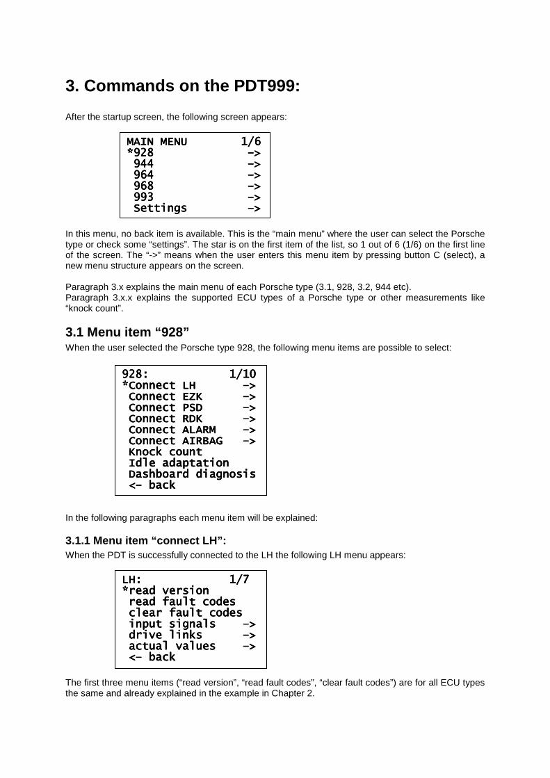
2.3.3 Select a menu item when only ignition on: The engine is NOT running, just ignition on, and the user connects to a certain ECU. Sometimes a command / menu item can only be executed when the engine IS running. When the user selects such a command while the engine not is running, the following will be visible: Example: Engine is NOT running, just ignition on: Main menu:
• Navigate to “928” and select EZK (start connection), • When connected, navigate and select to “actual values”,
The following screen appears:
• Select “ects”: The following screen appears:
The user should do:
1. Switch on the engine, 2. Navigate back to the EZK-actual values menu (main menu->928->EZK->connect, etc) 3. Perform the test again.
2.3.4 Connection error: Sometimes the communication with an ECU fails… Especially the alarm module version I00 and tiptronic ECU’s have difficulties with the communication, but also other modules can fail. What happens? The following messages appear on the screen: The user should press button C to return to the main menu of the Porsche type.
Actual values: 1/4*Actual values: 1/4*Actual values: 1/4*Actual values: 1/4* *ects*ects*ects*ects rpmrpmrpmrpm load signalload signalload signalload signal
ects: *ects: *ects: *ects: * Cannot perform test:Cannot perform test:Cannot perform test:Cannot perform test: Please start engine,Please start engine,Please start engine,Please start engine, connect& check againconnect& check againconnect& check againconnect& check again
! Connection ERROR !! Connection ERROR !! Connection ERROR !! Connection ERROR ! C = return to menuC = return to menuC = return to menuC = return to menu
3. Commands on the PDT999: After the startup screen, the following screen appears: In this menu, no back item is available. This is the “main menu” where the user can select the Porsche type or check some “settings”. The star is on the first item of the list, so 1 out of 6 (1/6) on the first line of the screen. The “->” means when the user enters this menu item by pressing button C (select), a new menu structure appears on the screen. Paragraph 3.x explains the main menu of each Porsche type (3.1, 928, 3.2, 944 etc). Paragraph 3.x.x explains the supported ECU types of a Porsche type or other measurements like “knock count”.
3.1 Menu item “928” When the user selected the Porsche type 928, the following menu items are possible to select: In the following paragraphs each menu item will be explained:
3.1.1 Menu item “connect LH”: When the PDT is successfully connected to the LH the following LH menu appears: The first three menu items (“read version”, “read fault codes”, “clear fault codes”) are for all ECU types the same and already explained in the example in Chapter 2.
928: 1/10928: 1/10928: 1/10928: 1/10 *Connect LH *Connect LH *Connect LH *Connect LH ––––>>>> Connect EZK Connect EZK Connect EZK Connect EZK ––––>>>> Connect PSD Connect PSD Connect PSD Connect PSD ––––>>>> Connect RDK Connect RDK Connect RDK Connect RDK ––––>>>> Connect ALARM Connect ALARM Connect ALARM Connect ALARM ––––>>>> Connect AIRBAG Connect AIRBAG Connect AIRBAG Connect AIRBAG ––––>>>> Knock countKnock countKnock countKnock count IdIdIdIdle adaptationle adaptationle adaptationle adaptation Dashboard diagnosisDashboard diagnosisDashboard diagnosisDashboard diagnosis <<<<–––– backbackbackback
MAIN MENU 1/6MAIN MENU 1/6MAIN MENU 1/6MAIN MENU 1/6 *928 *928 *928 *928 ––––>>>> 944 944 944 944 ––––>>>> 964 964 964 964 ––––>>>> 968 968 968 968 ––––>>>> 993 993 993 993 ––––>>>> Settings Settings Settings Settings ––––>>>>
LH: 1/7 LH: 1/7 LH: 1/7 LH: 1/7 *read version*read version*read version*read version read fault codesread fault codesread fault codesread fault codes clear fauclear fauclear fauclear fault codeslt codeslt codeslt codes input signals input signals input signals input signals ––––>>>> drive links drive links drive links drive links ––––>>>> actual values actual values actual values actual values ––––>>>> <<<<–––– backbackbackback
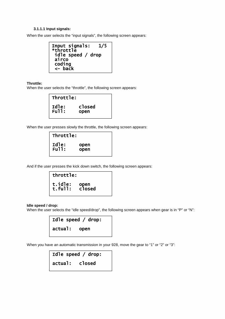
3.1.1.1 Input signals:
When the user selects the “input signals”, the following screen appears: Throttle: When the user selects the “throttle”, the following screen appears: When the user presses slowly the throttle, the following screen appears: And if the user presses the kick down switch, the following screen appears: Idle speed / drop: When the user selects the “idle speed/drop”, the following screen appears when gear is in “P” or “N”: When you have an automatic transmission in your 928, move the gear to “1” or “2” or “3”:
Input signals: 1/5 Input signals: 1/5 Input signals: 1/5 Input signals: 1/5 *throttle*throttle*throttle*throttle idle speed / dropidle speed / dropidle speed / dropidle speed / drop aircoaircoaircoairco codingcodingcodingcoding <<<<–––– backbackbackback
Throttle:Throttle:Throttle:Throttle: Idle:Idle:Idle:Idle: closedclosedclosedclosed Full:Full:Full:Full: openopenopenopen
Throttle:Throttle:Throttle:Throttle: Idle:Idle:Idle:Idle: openopenopenopen Full:Full:Full:Full: openopenopenopen
throttle:throttle:throttle:throttle: t.idle:t.idle:t.idle:t.idle: openopenopenopen t.full:t.full:t.full:t.full: closedclosedclosedclosed
Idle speed / drop:Idle speed / drop:Idle speed / drop:Idle speed / drop: actual:actual:actual:actual: openopenopenopen
Idle speed / drop:Idle speed / drop:Idle speed / drop:Idle speed / drop: actual:actual:actual:actual: closedclosedclosedclosed
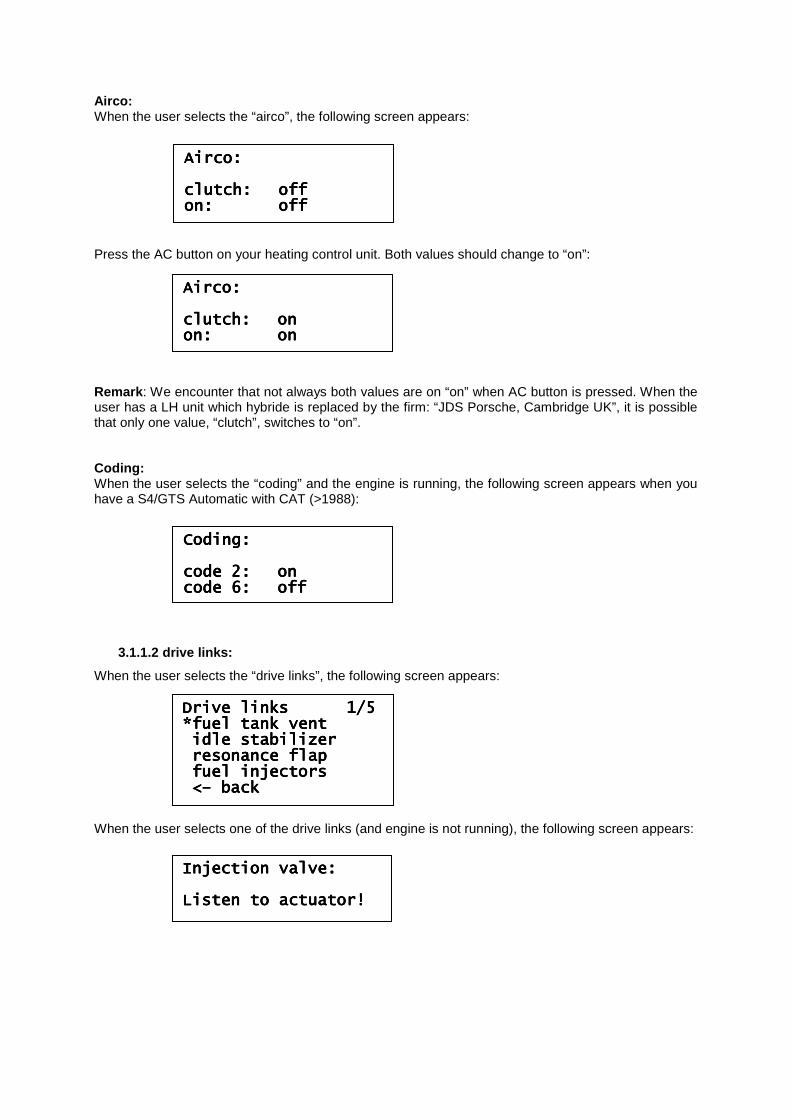
Airco: When the user selects the “airco”, the following screen appears: Press the AC button on your heating control unit. Both values should change to “on”: Remark : We encounter that not always both values are on “on” when AC button is pressed. When the user has a LH unit which hybride is replaced by the firm: “JDS Porsche, Cambridge UK”, it is possible that only one value, “clutch”, switches to “on”. Coding: When the user selects the “coding” and the engine is running, the following screen appears when you have a S4/GTS Automatic with CAT (>1988):
3.1.1.2 drive links:
When the user selects the “drive links”, the following screen appears: When the user selects one of the drive links (and engine is not running), the following screen appears:
Drive links 1/5Drive links 1/5Drive links 1/5Drive links 1/5 *fuel tank vent*fuel tank vent*fuel tank vent*fuel tank vent idle stabilizeridle stabilizeridle stabilizeridle stabilizer resonance flapresonance flapresonance flapresonance flap fuel injectorsfuel injectorsfuel injectorsfuel injectors <<<<–––– backbackbackback
Airco:Airco:Airco:Airco: clutch:clutch:clutch:clutch: offoffoffoff on:on:on:on: offoffoffoff
Airco:Airco:Airco:Airco: clutch:clutch:clutch:clutch: onononon on:on:on:on: onononon
Coding:Coding:Coding:Coding: cocococode 2:de 2:de 2:de 2: onononon code 6:code 6:code 6:code 6: offoffoffoff
Injection valve:Injection valve:Injection valve:Injection valve: Listen to actuator!Listen to actuator!Listen to actuator!Listen to actuator!
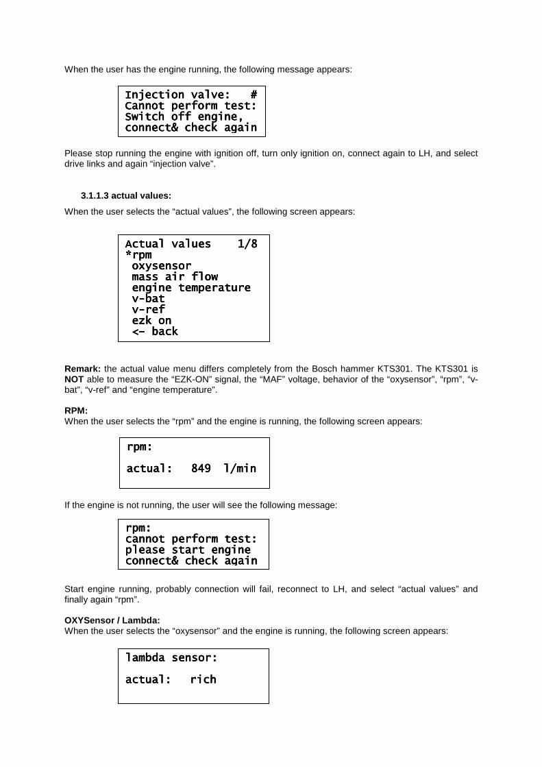
When the user has the engine running, the following message appears: Please stop running the engine with ignition off, turn only ignition on, connect again to LH, and select drive links and again “injection valve”.
3.1.1.3 actual values:
When the user selects the “actual values”, the following screen appears: Remark: the actual value menu differs completely from the Bosch hammer KTS301. The KTS301 is NOT able to measure the “EZK-ON” signal, the “MAF” voltage, behavior of the “oxysensor”, “rpm”, “v-bat”, “v-ref” and “engine temperature”. RPM: When the user selects the “rpm” and the engine is running, the following screen appears: If the engine is not running, the user will see the following message: Start engine running, probably connection will fail, reconnect to LH, and select “actual values” and finally again “rpm”. OXYSensor / Lambda: When the user selects the “oxysensor” and the engine is running, the following screen appears:
AcAcAcActual values 1/8 tual values 1/8 tual values 1/8 tual values 1/8 *rpm*rpm*rpm*rpm oxysensoroxysensoroxysensoroxysensor mass air flowmass air flowmass air flowmass air flow engine temperatureengine temperatureengine temperatureengine temperature vvvv----batbatbatbat vvvv----refrefrefref ezk onezk onezk onezk on <<<<–––– backbackbackback
Injection valve: #Injection valve: #Injection valve: #Injection valve: # Cannot perform test:Cannot perform test:Cannot perform test:Cannot perform test: Switch off engine,Switch off engine,Switch off engine,Switch off engine, connect& check againconnect& check againconnect& check againconnect& check again
rpm:rpm:rpm:rpm: actual:actual:actual:actual: 849849849849 l/minl/minl/minl/min
lambda sensor:lambda sensor:lambda sensor:lambda sensor: actual:actual:actual:actual: richrichrichrich ████████████████████████████████████████████████████████████████
rpm:rpm:rpm:rpm: cannot perform test:cannot perform test:cannot perform test:cannot perform test: please start engineplease start engineplease start engineplease start engine connect& check againconnect& check againconnect& check againconnect& check again
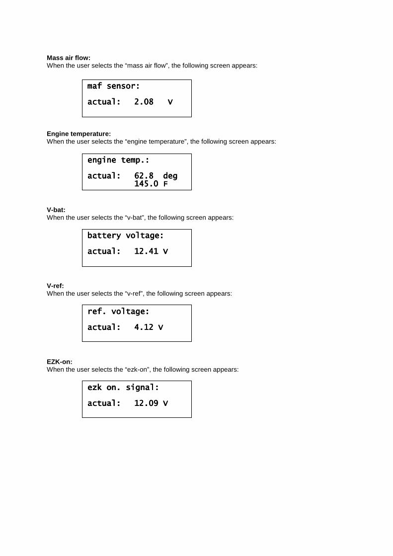
Mass air flow: When the user selects the “mass air flow”, the following screen appears: Engine temperature: When the user selects the “engine temperature”, the following screen appears: V-bat: When the user selects the “v-bat”, the following screen appears: V-ref: When the user selects the “v-ref”, the following screen appears: EZK-on: When the user selects the “ezk-on”, the following screen appears:
maf sensor:maf sensor:maf sensor:maf sensor: actual:actual:actual:actual: 2.08 V2.08 V2.08 V2.08 V
engine temp.:engine temp.:engine temp.:engine temp.: actual:actual:actual:actual: 62.8 deg62.8 deg62.8 deg62.8 deg 145.0 F145.0 F145.0 F145.0 F
battery voltage:battery voltage:battery voltage:battery voltage: actual:actual:actual:actual: 12.41 V12.41 V12.41 V12.41 V
ref. voltage:ref. voltage:ref. voltage:ref. voltage: actual:actual:actual:actual: 4.12 V4.12 V4.12 V4.12 V
ezk on. signal:ezk on. signal:ezk on. signal:ezk on. signal: actual:actual:actual:actual: 12.012.012.012.09 V9 V9 V9 V
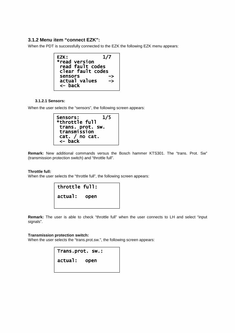
3.1.2 Menu item “connect EZK”: When the PDT is successfully connected to the EZK the following EZK menu appears:
3.1.2.1 Sensors:
When the user selects the “sensors”, the following screen appears: Remark: New additional commands versus the Bosch hammer KTS301. The “trans. Prot. Sw” (transmission protection switch) and “throttle full”. Throttle full: When the user selects the “throttle full”, the following screen appears: Remark: The user is able to check “throttle full” when the user connects to LH and select “input signals”. Transmission protection switch: When the user selects the “trans.prot.sw.”, the following screen appears:
EZK: 1/7 EZK: 1/7 EZK: 1/7 EZK: 1/7 *read version*read version*read version*read version read fault codesread fault codesread fault codesread fault codes clear fault codesclear fault codesclear fault codesclear fault codes sensors sensors sensors sensors ––––>>>> actual values actual values actual values actual values ––––>>>> <<<<–––– backbackbackback
Sensors: 1/5 Sensors: 1/5 Sensors: 1/5 Sensors: 1/5 *throttl*throttl*throttl*throttle fulle fulle fulle full trans. prot. sw.trans. prot. sw.trans. prot. sw.trans. prot. sw. transmissiontransmissiontransmissiontransmission cat. / no cat.cat. / no cat.cat. / no cat.cat. / no cat. <<<<–––– backbackbackback
throttle full:throttle full:throttle full:throttle full: actual:actual:actual:actual: openopenopenopen
Trans.prot. sw.:Trans.prot. sw.:Trans.prot. sw.:Trans.prot. sw.: actual:actual:actual:actual: openopenopenopen
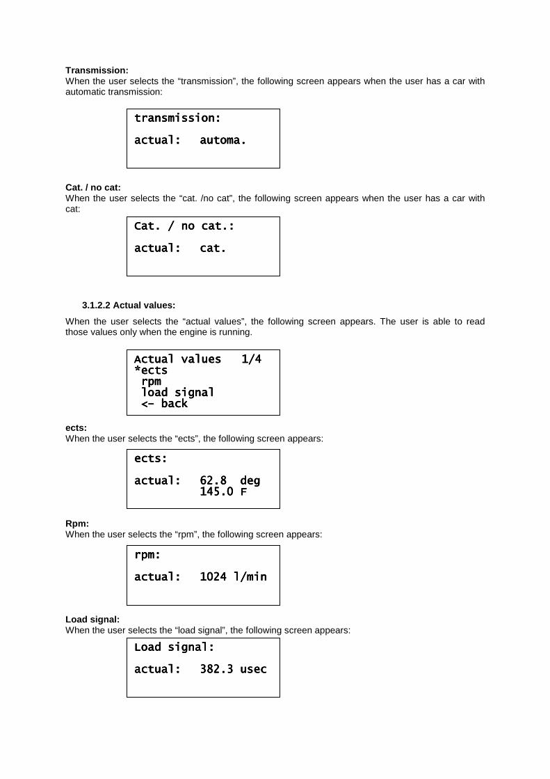
Transmission: When the user selects the “transmission”, the following screen appears when the user has a car with automatic transmission: Cat. / no cat: When the user selects the “cat. /no cat”, the following screen appears when the user has a car with cat:
3.1.2.2 Actual values:
When the user selects the “actual values”, the following screen appears. The user is able to read those values only when the engine is running. ects: When the user selects the “ects”, the following screen appears: Rpm: When the user selects the “rpm”, the following screen appears: Load signal: When the user selects the “load signal”, the following screen appears:
Actual values 1/4 Actual values 1/4 Actual values 1/4 Actual values 1/4 *ects*ects*ects*ects rpmrpmrpmrpm load signalload signalload signalload signal <<<<–––– backbackbackback
transmission:transmission:transmission:transmission: actual:actual:actual:actual: automa.automa.automa.automa.
Cat. / no cat.:Cat. / no cat.:Cat. / no cat.:Cat. / no cat.: actual:actual:actual:actual: cat.cat.cat.cat.
ects:ects:ects:ects: actual:actual:actual:actual: 62.8 deg62.8 deg62.8 deg62.8 deg 145.0 F145.0 F145.0 F145.0 F
rpm:rpm:rpm:rpm: actual:actual:actual:actual: 1024 l/min1024 l/min1024 l/min1024 l/min
Load signal:Load signal:Load signal:Load signal: actual:actual:actual:actual: 382.3 usec382.3 usec382.3 usec382.3 usec
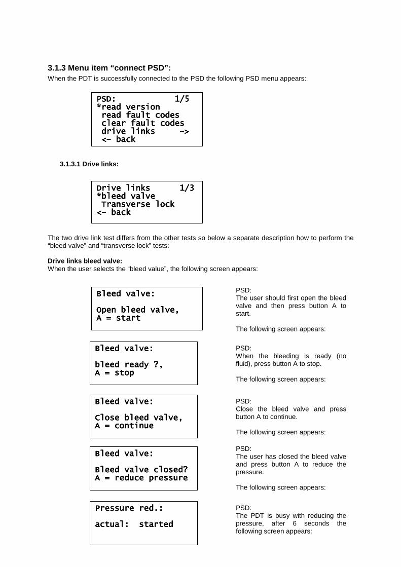
3.1.3 Menu item “connect PSD”: When the PDT is successfully connected to the PSD the following PSD menu appears:
3.1.3.1 Drive links:
The two drive link test differs from the other tests so below a separate description how to perform the “bleed valve” and “transverse lock” tests: Drive links bleed valve: When the user selects the “bleed value”, the following screen appears:
PSD: 1/5 PSD: 1/5 PSD: 1/5 PSD: 1/5 *read version*read version*read version*read version read fault codesread fault codesread fault codesread fault codes clear fault codesclear fault codesclear fault codesclear fault codes drive links drive links drive links drive links ––––>>>> <<<<–––– backbackbackback
Drive links 1/3 Drive links 1/3 Drive links 1/3 Drive links 1/3 *bleed valve*bleed valve*bleed valve*bleed valve Transverse lockTransverse lockTransverse lockTransverse lock <<<<–––– backbackbackback
Bleed valve:Bleed valve:Bleed valve:Bleed valve: Open bleed valve,Open bleed valve,Open bleed valve,Open bleed valve, A = startA = startA = startA = start
PSD: The user should first open the bleed valve and then press button A to start. The following screen appears:
Bleed valve:Bleed valve:Bleed valve:Bleed valve: bleed ready ?,bleed ready ?,bleed ready ?,bleed ready ?, A = stopA = stopA = stopA = stop
PSD: When the bleeding is ready (no fluid), press button A to stop. The following screen appears:
Bleed valve:Bleed valve:Bleed valve:Bleed valve: Close bleed valve,Close bleed valve,Close bleed valve,Close bleed valve, A = continueA = continueA = continueA = continue
PSD: Close the bleed valve and press button A to continue. The following screen appears:
Bleed valve:Bleed valve:Bleed valve:Bleed valve: Bleed valve closed?Bleed valve closed?Bleed valve closed?Bleed valve closed? A = reduce pressA = reduce pressA = reduce pressA = reduce pressureureureure
PSD: The user has closed the bleed valve and press button A to reduce the pressure. The following screen appears:
Pressure red.:Pressure red.:Pressure red.:Pressure red.: actual: startedactual: startedactual: startedactual: started
PSD: The PDT is busy with reducing the pressure, after 6 seconds the following screen appears:
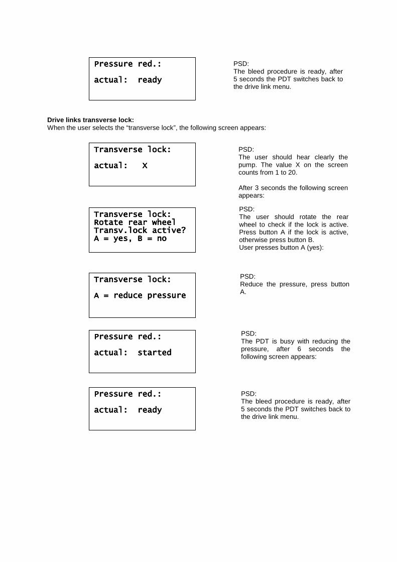
Drive links transverse lock: When the user selects the “transverse lock”, the following screen appears:
PresPresPresPressure red.:sure red.:sure red.:sure red.: actual: readyactual: readyactual: readyactual: ready
PSD: The bleed procedure is ready, after 5 seconds the PDT switches back to the drive link menu.
Transverse lock:Transverse lock:Transverse lock:Transverse lock: actual: Xactual: Xactual: Xactual: X
PSD: The user should hear clearly the pump. The value X on the screen counts from 1 to 20. After 3 seconds the following screen appears:
Transverse lock:Transverse lock:Transverse lock:Transverse lock: Rotate rear wheelRotate rear wheelRotate rear wheelRotate rear wheel Transv.lock actiTransv.lock actiTransv.lock actiTransv.lock active?ve?ve?ve? A = yes, B = noA = yes, B = noA = yes, B = noA = yes, B = no
PSD: The user should rotate the rear wheel to check if the lock is active. Press button A if the lock is active, otherwise press button B. User presses button A (yes):
TraTraTraTransverse lock:nsverse lock:nsverse lock:nsverse lock: A = reduce pressureA = reduce pressureA = reduce pressureA = reduce pressure
Pressure red.: Pressure red.: Pressure red.: Pressure red.: actual: startedactual: startedactual: startedactual: started
PSD: The PDT is busy with reducing the pressure, after 6 seconds the following screen appears:
Pressure red.:Pressure red.:Pressure red.:Pressure red.: actual: readyactual: readyactual: readyactual: ready
PSD: The bleed procedure is ready, after 5 seconds the PDT switches back to the drive link menu.
PSD: Reduce the pressure, press button A.
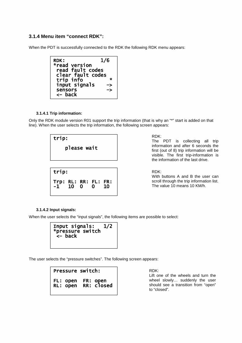
3.1.4 Menu item “connect RDK”: When the PDT is successfully connected to the RDK the following RDK menu appears:
3.1.4.1 Trip information:
Only the RDK module version R01 support the trip information (that is why an “*” start is added on that line). When the user selects the trip information, the following screen appears:
3.1.4.2 Input signals:
When the user selects the “input signals”, the following items are possible to select: The user selects the “pressure switches”. The following screen appears:
RDK: 1/6 RDK: 1/6 RDK: 1/6 RDK: 1/6 *read version*read version*read version*read version read fault codesread fault codesread fault codesread fault codes clear fault codesclear fault codesclear fault codesclear fault codes trip info *trip info *trip info *trip info * input signals input signals input signals input signals ––––>>>> sensors sensors sensors sensors ––––>>>> <<<<–––– backbackbackback
trip:trip:trip:trip: please wait please wait please wait please wait
RDK: The PDT is collecting all trip information and after 6 seconds the first (out of 8) trip information will be visible. The first trip-information is the information of the last drive.
trip:trip:trip:trip: Trp: RL: RR: FL: FR:Trp: RL: RR: FL: FR:Trp: RL: RR: FL: FR:Trp: RL: RR: FL: FR: ----1 10 0 0 101 10 0 0 101 10 0 0 101 10 0 0 10
RDK: With buttons A and B the user can scroll through the trip information list. The value 10 means 10 KM/h.
Input signals: 1/2Input signals: 1/2Input signals: 1/2Input signals: 1/2 *pressure switch*pressure switch*pressure switch*pressure switch <<<<–––– backbackbackback
Pressure switch:Pressure switch:Pressure switch:Pressure switch: FL: open FR: openFL: open FR: openFL: open FR: openFL: open FR: open RL: open RR: closedRL: open RR: closedRL: open RR: closedRL: open RR: closed
RDK: Lift one of the wheels and turn the wheel slowly… suddenly the user should see a transition from “open” to “closed”.
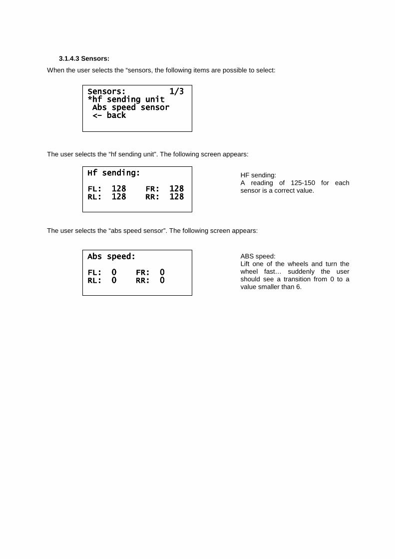
3.1.4.3 Sensors:
When the user selects the “sensors, the following items are possible to select: The user selects the “hf sending unit”. The following screen appears: The user selects the “abs speed sensor”. The following screen appears:
SensSensSensSensors: 1/3ors: 1/3ors: 1/3ors: 1/3 *hf sending unit*hf sending unit*hf sending unit*hf sending unit Abs speed sensorAbs speed sensorAbs speed sensorAbs speed sensor <<<<–––– backbackbackback
Abs speed:Abs speed:Abs speed:Abs speed: FL: 0 FR: 0FL: 0 FR: 0FL: 0 FR: 0FL: 0 FR: 0 RL: 0 RR: 0RL: 0 RR: 0RL: 0 RR: 0RL: 0 RR: 0
ABS speed: Lift one of the wheels and turn the wheel fast… suddenly the user should see a transition from 0 to a value smaller than 6.
Hf sending:Hf sending:Hf sending:Hf sending: FL: 128 FR: FL: 128 FR: FL: 128 FR: FL: 128 FR: 128128128128 RL: 128 RR: 128RL: 128 RR: 128RL: 128 RR: 128RL: 128 RR: 128
HF sending: A reading of 125-150 for each sensor is a correct value.
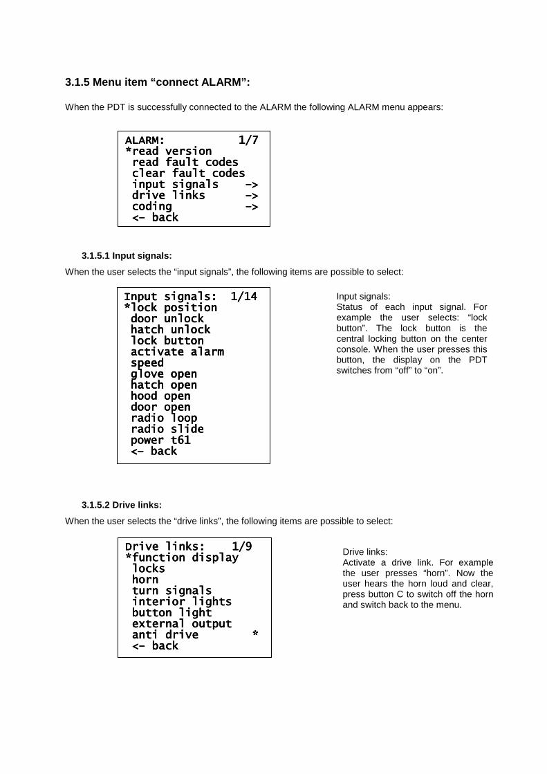
3.1.5 Menu item “connect ALARM”: When the PDT is successfully connected to the ALARM the following ALARM menu appears:
3.1.5.1 Input signals:
When the user selects the “input signals”, the following items are possible to select:
3.1.5.2 Drive links:
When the user selects the “drive links”, the following items are possible to select:
ALARM: ALARM: ALARM: ALARM: 1/71/71/71/7 *read version*read version*read version*read version read fault codesread fault codesread fault codesread fault codes clear fault codesclear fault codesclear fault codesclear fault codes input signals input signals input signals input signals ––––>>>> drive links drive links drive links drive links ––––>>>> coding coding coding coding ––––>>>> <<<<–––– backbackbackback
Input signals: 1/14 Input signals: 1/14 Input signals: 1/14 Input signals: 1/14 *lock position*lock position*lock position*lock position door unlockdoor unlockdoor unlockdoor unlock hatch unlockhatch unlockhatch unlockhatch unlock lock buttonlock buttonlock buttonlock button activate alarmactivate alarmactivate alarmactivate alarm speedspeedspeedspeed glove openglove openglove openglove open hatch openhatch openhatch openhatch open hood openhood openhood openhood open door opendoor opendoor opendoor open radio loopradio loopradio loopradio loop radio slideradio slideradio slideradio slide power t61power t61power t61power t61 <<<<–––– backbackbackback
Drive links: 1/9 Drive links: 1/9 Drive links: 1/9 Drive links: 1/9 *function display*function display*function display*function display lockslockslockslocks hornhornhornhorn turn signalsturn signalsturn signalsturn signals interior lightsinterior lightsinterior lightsinterior lights button lightbutton lightbutton lightbutton light external outputexternal outputexternal outputexternal output anti drive *anti drive *anti drive *anti drive * <<<<–––– backbackbackback
Input signals: Status of each input signal. For example the user selects: “lock button”. The lock button is the central locking button on the center console. When the user presses this button, the display on the PDT switches from “off” to “on”.
Drive links: Activate a drive link. For example the user presses “horn”. Now the user hears the horn loud and clear, press button C to switch off the horn and switch back to the menu.
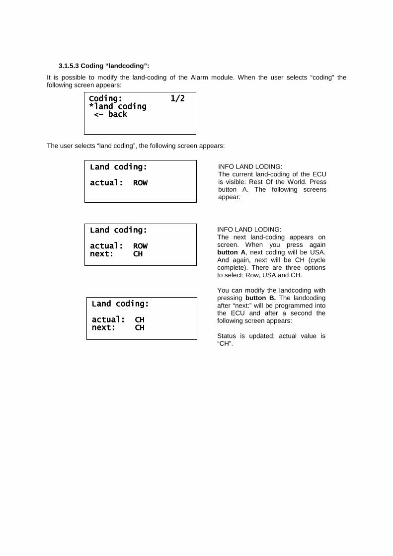
3.1.5.3 Coding “landcoding”:
It is possible to modify the land-coding of the Alarm module. When the user selects “coding” the following screen appears: The user selects “land coding”, the following screen appears:
Coding: 1/2Coding: 1/2Coding: 1/2Coding: 1/2 *land coding*land coding*land coding*land coding <<<<–––– backbackbackback
Land coding:Land coding:Land coding:Land coding: actual: ROWactual: ROWactual: ROWactual: ROW
INFO LAND LODING: The current land-coding of the ECU is visible: Rest Of the World. Press button A. The following screens appear:
Land coding:Land coding:Land coding:Land coding: actactactactual: ROWual: ROWual: ROWual: ROW next: CHnext: CHnext: CHnext: CH
INFO LAND LODING: The next land-coding appears on screen. When you press again button A , next coding will be USA. And again, next will be CH (cycle complete). There are three options to select: Row, USA and CH. You can modify the landcoding with pressing button B. The landcoding after “next:” will be programmed into the ECU and after a second the following screen appears: Status is updated; actual value is “CH”.
Land coding:Land coding:Land coding:Land coding: actual: CHactual: CHactual: CHactual: CH next: CHnext: CHnext: CHnext: CH
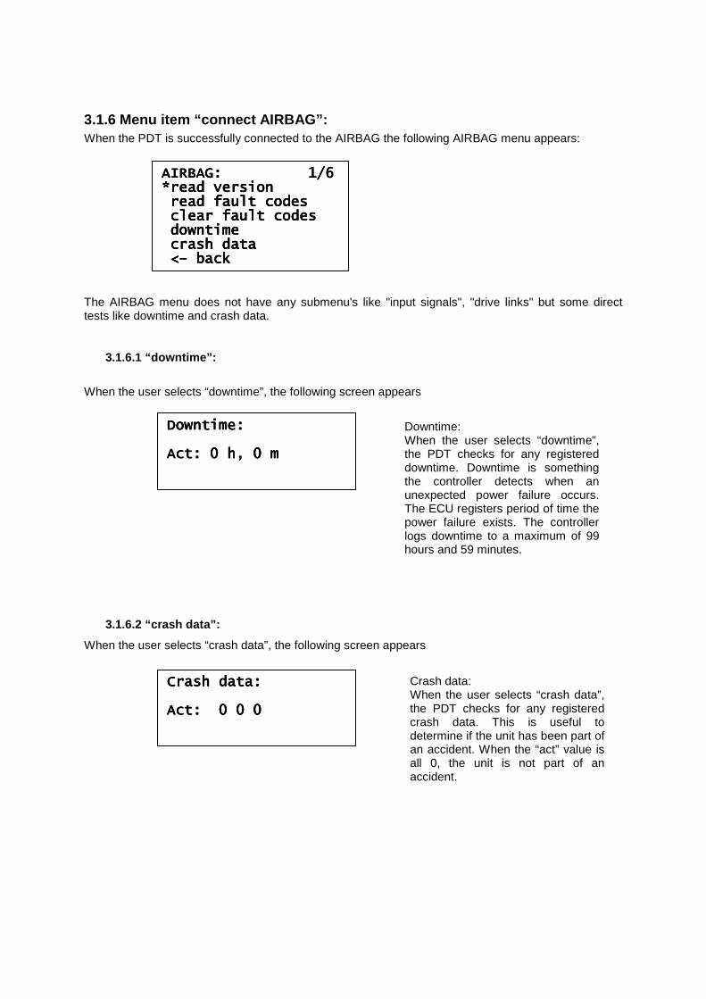
3.1.6 Menu item “connect AIRBAG”: When the PDT is successfully connected to the AIRBAG the following AIRBAG menu appears: The AIRBAG menu does not have any submenu's like "input signals", "drive links" but some direct tests like downtime and crash data.
3.1.6.1 “downtime”:
When the user selects “downtime”, the following screen appears
3.1.6.2 “crash data”:
When the user selects “crash data”, the following screen appears
AIRBAG: 1/6AIRBAG: 1/6AIRBAG: 1/6AIRBAG: 1/6 *read version*read version*read version*read version read fault codesread fault codesread fault codesread fault codes clear fault codesclear fault codesclear fault codesclear fault codes downtdowntdowntdowntimeimeimeime crash datacrash datacrash datacrash data <<<<–––– backbackbackback
Downtime:Downtime:Downtime:Downtime: Act: 0 h, 0 mAct: 0 h, 0 mAct: 0 h, 0 mAct: 0 h, 0 m
Downtime: When the user selects “downtime”, the PDT checks for any registered downtime. Downtime is something the controller detects when an unexpected power failure occurs. The ECU registers period of time the power failure exists. The controller logs downtime to a maximum of 99 hours and 59 minutes.
Crash data:Crash data:Crash data:Crash data: Act: 0 0 0Act: 0 0 0Act: 0 0 0Act: 0 0 0
Crash data: When the user selects “crash data”, the PDT checks for any registered crash data. This is useful to determine if the unit has been part of an accident. When the “act” value is all 0, the unit is not part of an accident.
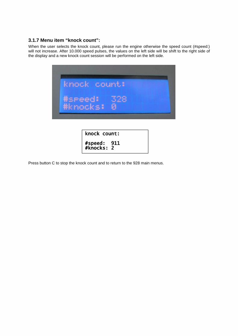
3.1.7 Menu item “knock count”: When the user selects the knock count, please run the engine otherwise the speed count (#speed:) will not increase. After 10.000 speed pulses, the values on the left side will be shift to the right side of the display and a new knock count session will be performed on the left side.
Press button C to stop the knock count and to return to the 928 main menus.
knock count:knock count:knock count:knock count: ####speed: 911speed: 911speed: 911speed: 911 #knocks: 2#knocks: 2#knocks: 2#knocks: 2
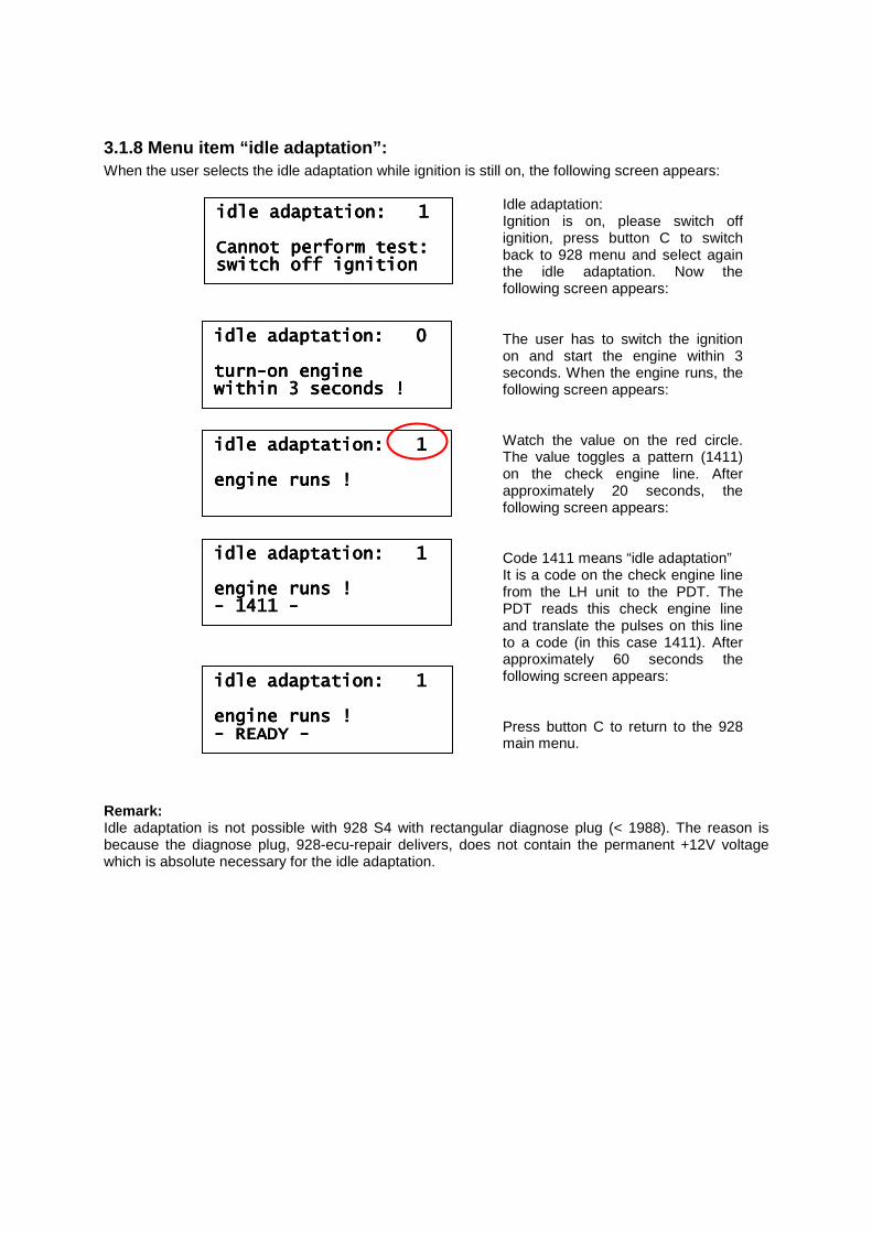
3.1.8 Menu item “idle adaptation”: When the user selects the idle adaptation while ignition is still on, the following screen appears: Remark: Idle adaptation is not possible with 928 S4 with rectangular diagnose plug (< 1988). The reason is because the diagnose plug, 928-ecu-repair delivers, does not contain the permanent +12V voltage which is absolute necessary for the idle adaptation.
idle adaptation: 1idle adaptation: 1idle adaptation: 1idle adaptation: 1 Cannot perform test:Cannot perform test:Cannot perform test:Cannot perform test: switch off ignitionswitch off ignitionswitch off ignitionswitch off ignition
idle adaptation: 0idle adaptation: 0idle adaptation: 0idle adaptation: 0 turnturnturnturn----on engineon engineon engineon engine within 3 seconds !within 3 seconds !within 3 seconds !within 3 seconds !
idle adaptation: 1idle adaptation: 1idle adaptation: 1idle adaptation: 1 engine runs engine runs engine runs engine runs !!!!
idle adaptation: 1idle adaptation: 1idle adaptation: 1idle adaptation: 1 engine runs !engine runs !engine runs !engine runs ! ---- 1411 1411 1411 1411 ----
idle adaptation: 1idle adaptation: 1idle adaptation: 1idle adaptation: 1 engine runs !engine runs !engine runs !engine runs ! ---- READY READY READY READY ----
Idle adaptation: Ignition is on, please switch off ignition, press button C to switch back to 928 menu and select again the idle adaptation. Now the following screen appears: The user has to switch the ignition on and start the engine within 3 seconds. When the engine runs, the following screen appears: Watch the value on the red circle. The value toggles a pattern (1411) on the check engine line. After approximately 20 seconds, the following screen appears: Code 1411 means “idle adaptation” It is a code on the check engine line from the LH unit to the PDT. The PDT reads this check engine line and translate the pulses on this line to a code (in this case 1411). After approximately 60 seconds the following screen appears: Press button C to return to the 928 main menu.
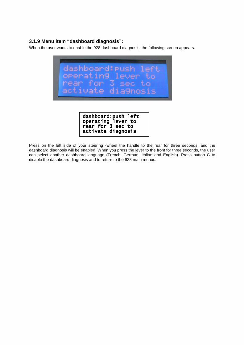
3.1.9 Menu item “dashboard diagnosis”: When the user wants to enable the 928 dashboard diagnosis, the following screen appears.
Press on the left side of your steering -wheel the handle to the rear for three seconds, and the dashboard diagnosis will be enabled. When you press the lever to the front for three seconds, the user can select another dashboard language (French, German, Italian and English). Press button C to disable the dashboard diagnosis and to return to the 928 main menus.
dashboard:push leftdashboard:push leftdashboard:push leftdashboard:push left operating lever tooperating lever tooperating lever tooperating lever to rear for 3 sec torear for 3 sec torear for 3 sec torear for 3 sec to activate diagnosisactivate diagnosisactivate diagnosisactivate diagnosis
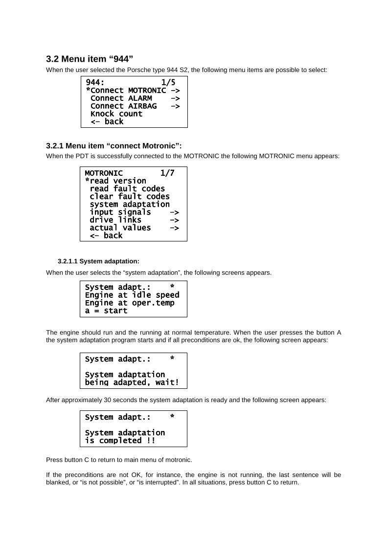
3.2 Menu item “944” When the user selected the Porsche type 944 S2, the following menu items are possible to select:
3.2.1 Menu item “connect Motronic”: When the PDT is successfully connected to the MOTRONIC the following MOTRONIC menu appears:
3.2.1.1 System adaptation:
When the user selects the “system adaptation”, the following screens appears. The engine should run and the running at normal temperature. When the user presses the button A the system adaptation program starts and if all preconditions are ok, the following screen appears: After approximately 30 seconds the system adaptation is ready and the following screen appears: Press button C to return to main menu of motronic. If the preconditions are not OK, for instance, the engine is not running, the last sentence will be blanked, or “is not possible”, or “is interrupted”. In all situations, press button C to return.
944: 1/5 944: 1/5 944: 1/5 944: 1/5 *Connect MOTRONIC *Connect MOTRONIC *Connect MOTRONIC *Connect MOTRONIC ––––>>>> Connect ALARM Connect ALARM Connect ALARM Connect ALARM ––––>>>> Connect AIRBAG Connect AIRBAG Connect AIRBAG Connect AIRBAG ––––>>>> Knock countKnock countKnock countKnock count <<<<–––– backbackbackback
MOTRONIC 1/7 MOTRONIC 1/7 MOTRONIC 1/7 MOTRONIC 1/7 *read version*read version*read version*read version read fault codesread fault codesread fault codesread fault codes clear fault codesclear fault codesclear fault codesclear fault codes system adaptationsystem adaptationsystem adaptationsystem adaptation input signals input signals input signals input signals ––––>>>> drive links drive links drive links drive links ––––>>>> actual values actual values actual values actual values ––––>>>> <<<<–––– backbackbackback
System adapt.: *System adapt.: *System adapt.: *System adapt.: * Engine at idle speedEngine at idle speedEngine at idle speedEngine at idle speed Engine atEngine atEngine atEngine at oper.tempoper.tempoper.tempoper.temp a = starta = starta = starta = start
System adapt.: *System adapt.: *System adapt.: *System adapt.: * System adaptationSystem adaptationSystem adaptationSystem adaptation being adapted, wait!being adapted, wait!being adapted, wait!being adapted, wait!
System adapt.: *System adapt.: *System adapt.: *System adapt.: * System adaptationSystem adaptationSystem adaptationSystem adaptation is completed !!is completed !!is completed !!is completed !!
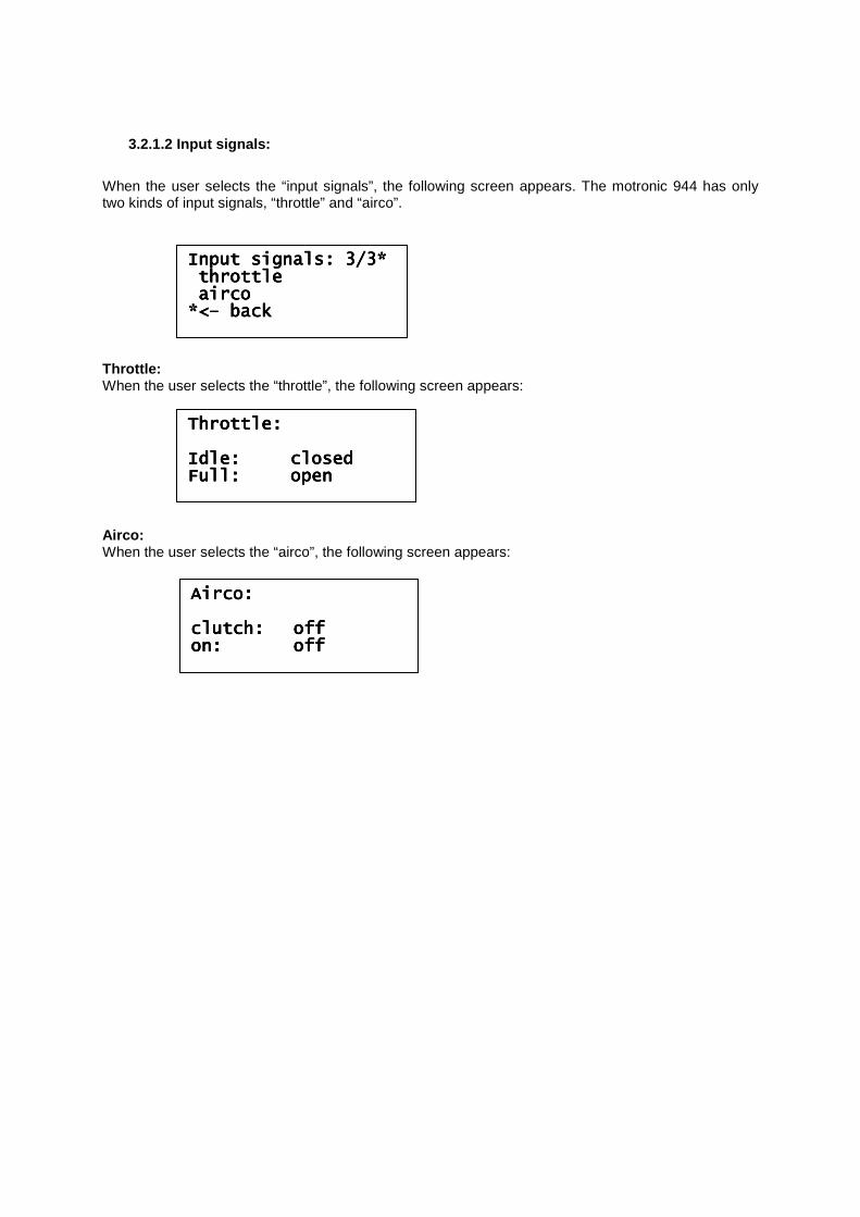
3.2.1.2 Input signals:
When the user selects the “input signals”, the following screen appears. The motronic 944 has only two kinds of input signals, “throttle” and “airco”. Throttle: When the user selects the “throttle”, the following screen appears: Airco: When the user selects the “airco”, the following screen appears:
Input signals: 3/3*Input signals: 3/3*Input signals: 3/3*Input signals: 3/3* throttlethrottlethrottlethrottle aircoaircoaircoairco *<*<*<*<–––– backbackbackback
Throttle:Throttle:Throttle:Throttle: Idle:Idle:Idle:Idle: closedclosedclosedclosed Full:Full:Full:Full: openopenopenopen
Airco:Airco:Airco:Airco: clutch:clutch:clutch:clutch: offoffoffoff on:on:on:on: offoffoffoff
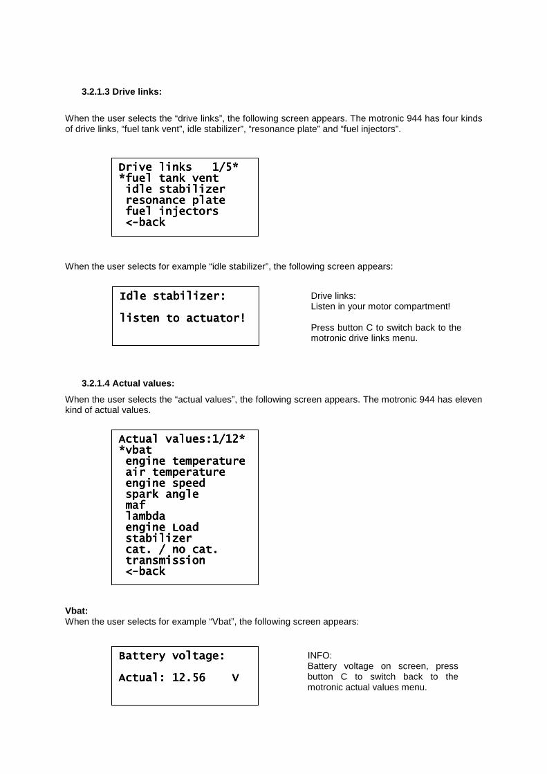
3.2.1.3 Drive links:
When the user selects the “drive links”, the following screen appears. The motronic 944 has four kinds of drive links, “fuel tank vent”, idle stabilizer”, “resonance plate” and “fuel injectors”. When the user selects for example “idle stabilizer”, the following screen appears:
3.2.1.4 Actual values:
When the user selects the “actual values”, the following screen appears. The motronic 944 has eleven kind of actual values. Vbat: When the user selects for example “Vbat”, the following screen appears:
Drive links 1/5*Drive links 1/5*Drive links 1/5*Drive links 1/5* *fuel tank vent*fuel tank vent*fuel tank vent*fuel tank vent idle stabilidle stabilidle stabilidle stabilizerizerizerizer resonance plateresonance plateresonance plateresonance plate fuel injectorsfuel injectorsfuel injectorsfuel injectors <<<<----backbackbackback
Actual values:1/12*Actual values:1/12*Actual values:1/12*Actual values:1/12* *vbat*vbat*vbat*vbat engine temperatureengine temperatureengine temperatureengine temperature air temperatureair temperatureair temperatureair temperature engine speedengine speedengine speedengine speed spark anglespark anglespark anglespark angle mafmafmafmaf lambdalambdalambdalambda engine Loadengine Loadengine Loadengine Load stabilizerstabilizerstabilizerstabilizer cat. / no cat.cat. / no cat.cat. / no cat.cat. / no cat. transmissiontransmissiontransmissiontransmission <<<<----bbbbackackackack
Idle stabilizer:Idle stabilizer:Idle stabilizer:Idle stabilizer: listen to actuator!listen to actuator!listen to actuator!listen to actuator!
Drive links: Listen in your motor compartment! Press button C to switch back to the motronic drive links menu.
Battery voltage:Battery voltage:Battery voltage:Battery voltage: Actual: 12.56 VActual: 12.56 VActual: 12.56 VActual: 12.56 V
INFO: Battery voltage on screen, press button C to switch back to the motronic actual values menu.
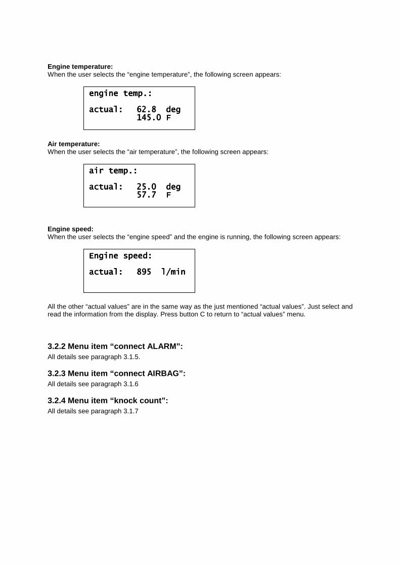
Engine temperature: When the user selects the “engine temperature”, the following screen appears: Air temperature: When the user selects the “air temperature”, the following screen appears: Engine speed: When the user selects the “engine speed” and the engine is running, the following screen appears: All the other “actual values” are in the same way as the just mentioned “actual values”. Just select and read the information from the display. Press button C to return to “actual values” menu.
3.2.2 Menu item “connect ALARM”: All details see paragraph 3.1.5.
3.2.3 Menu item “connect AIRBAG”: All details see paragraph 3.1.6
3.2.4 Menu item “knock count”: All details see paragraph 3.1.7
engine temp.:engine temp.:engine temp.:engine temp.: actual:actual:actual:actual: 62.8 deg62.8 deg62.8 deg62.8 deg 145.0 F145.0 F145.0 F145.0 F
air temp.:air temp.:air temp.:air temp.: actual:actual:actual:actual: 25.0 deg25.0 deg25.0 deg25.0 deg 57.7 F57.7 F57.7 F57.7 F
Engine speed:Engine speed:Engine speed:Engine speed: actual:actual:actual:actual: 895 l/min895 l/min895 l/min895 l/min
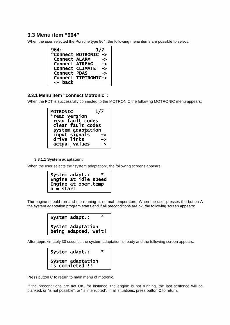
3.3 Menu item “964” When the user selected the Porsche type 964, the following menu items are possible to select:
3.3.1 Menu item “connect Motronic”: When the PDT is successfully connected to the MOTRONIC the following MOTRONIC menu appears:
3.3.1.1 System adaptation:
When the user selects the “system adaptation”, the following screens appears. The engine should run and the running at normal temperature. When the user presses the button A the system adaptation program starts and if all preconditions are ok, the following screen appears: After approximately 30 seconds the system adaptation is ready and the following screen appears: Press button C to return to main menu of motronic. If the preconditions are not OK, for instance, the engine is not running, the last sentence will be blanked, or “is not possible”, or “is interrupted”. In all situations, press button C to return.
964: 1/7 964: 1/7 964: 1/7 964: 1/7 *Connect MOTRONIC *Connect MOTRONIC *Connect MOTRONIC *Connect MOTRONIC ––––>>>> Connect ALARM Connect ALARM Connect ALARM Connect ALARM ––––>>>> Connect AIRBAG Connect AIRBAG Connect AIRBAG Connect AIRBAG ––––>>>> Connect CLIMATE Connect CLIMATE Connect CLIMATE Connect CLIMATE ––––>>>> Connect PDAS Connect PDAS Connect PDAS Connect PDAS ––––>>>> Connect TIPTRONICConnect TIPTRONICConnect TIPTRONICConnect TIPTRONIC---->>>> <<<<–––– backbackbackback
MOTRONIC 1/7 MOTRONIC 1/7 MOTRONIC 1/7 MOTRONIC 1/7 *read version*read version*read version*read version read fault codesread fault codesread fault codesread fault codes clear fault codesclear fault codesclear fault codesclear fault codes system adaptationsystem adaptationsystem adaptationsystem adaptation ininininput signals put signals put signals put signals ––––>>>> drive links drive links drive links drive links ––––>>>> actual values actual values actual values actual values ––––>>>> <<<<–––– backbackbackback
System adapt.: *System adapt.: *System adapt.: *System adapt.: * Engine at idle speedEngine at idle speedEngine at idle speedEngine at idle speed Engine at oper.tempEngine at oper.tempEngine at oper.tempEngine at oper.temp a = starta = starta = starta = start
System adapt.: *System adapt.: *System adapt.: *System adapt.: * System adaptationSystem adaptationSystem adaptationSystem adaptation being adapted, wait!being adapted, wait!being adapted, wait!being adapted, wait!
System adapt.: *System adapt.: *System adapt.: *System adapt.: * System adaptationSystem adaptationSystem adaptationSystem adaptation is completed !!is completed !!is completed !!is completed !!
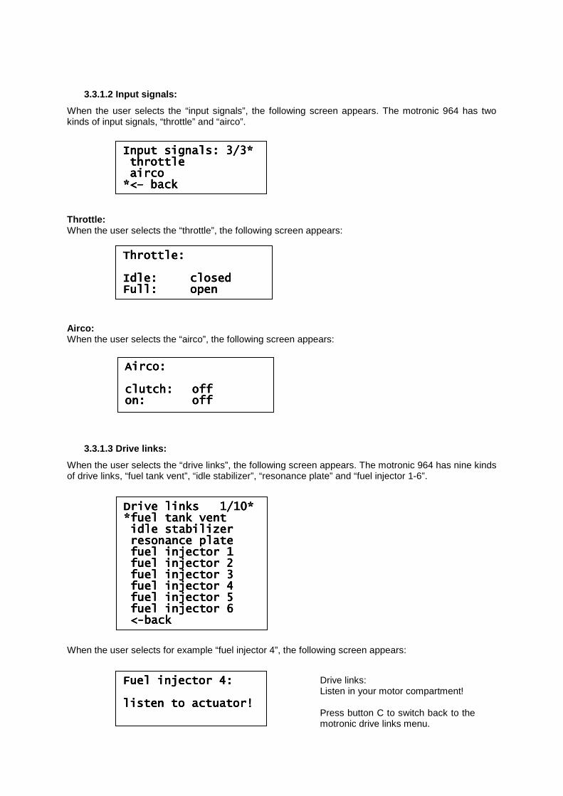
3.3.1.2 Input signals:
When the user selects the “input signals”, the following screen appears. The motronic 964 has two kinds of input signals, “throttle” and “airco”. Throttle: When the user selects the “throttle”, the following screen appears: Airco: When the user selects the “airco”, the following screen appears:
3.3.1.3 Drive links:
When the user selects the “drive links”, the following screen appears. The motronic 964 has nine kinds of drive links, “fuel tank vent”, “idle stabilizer”, “resonance plate” and “fuel injector 1-6”. When the user selects for example “fuel injector 4”, the following screen appears:
Drive links 1/10*Drive links 1/10*Drive links 1/10*Drive links 1/10* *fuel tank vent*fuel tank vent*fuel tank vent*fuel tank vent idle stabilizeridle stabilizeridle stabilizeridle stabilizer resonance plateresonance plateresonance plateresonance plate fufufufuel injector 1el injector 1el injector 1el injector 1 fuel injector 2fuel injector 2fuel injector 2fuel injector 2 fuel injector 3fuel injector 3fuel injector 3fuel injector 3 fuel injector 4fuel injector 4fuel injector 4fuel injector 4 fuel injector 5fuel injector 5fuel injector 5fuel injector 5 fuel injector 6fuel injector 6fuel injector 6fuel injector 6 <<<<----backbackbackback
Input signals: 3/3*Input signals: 3/3*Input signals: 3/3*Input signals: 3/3* throttlethrottlethrottlethrottle aircoaircoaircoairco *<*<*<*<–––– backbackbackback
Throttle:Throttle:Throttle:Throttle: Idle:Idle:Idle:Idle: closedclosedclosedclosed Full:Full:Full:Full: openopenopenopen
Airco:Airco:Airco:Airco: clutch:clutch:clutch:clutch: offoffoffoff on:on:on:on: offoffoffoff
Fuel injector 4:Fuel injector 4:Fuel injector 4:Fuel injector 4: listen to actuator!listen to actuator!listen to actuator!listen to actuator!
Drive links: Listen in your motor compartment! Press button C to switch back to the motronic drive links menu.
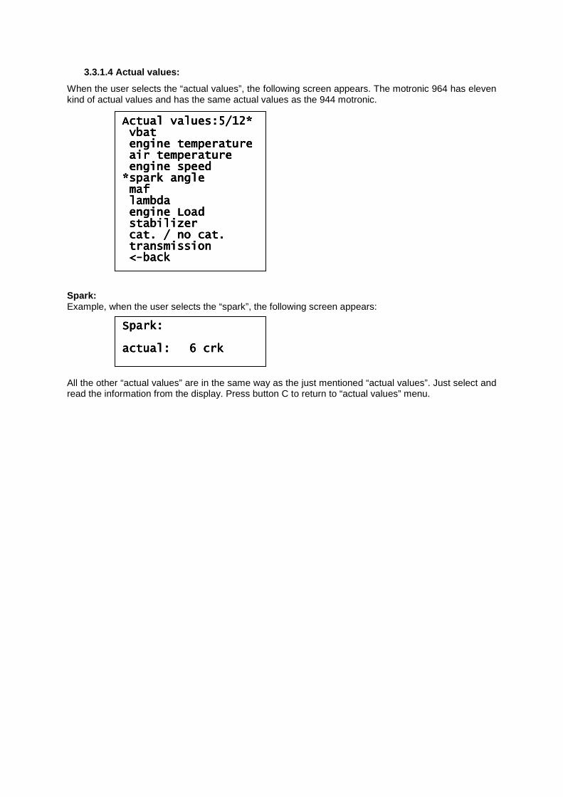
3.3.1.4 Actual values:
When the user selects the “actual values”, the following screen appears. The motronic 964 has eleven kind of actual values and has the same actual values as the 944 motronic. Spark: Example, when the user selects the “spark”, the following screen appears: All the other “actual values” are in the same way as the just mentioned “actual values”. Just select and read the information from the display. Press button C to return to “actual values” menu.
Actual values:5/12*Actual values:5/12*Actual values:5/12*Actual values:5/12* vbatvbatvbatvbat engine temperatureengine temperatureengine temperatureengine temperature air temperatureair temperatureair temperatureair temperature engine speedengine speedengine speedengine speed *spark angle*spark angle*spark angle*spark angle mafmafmafmaf lambdalambdalambdalambda engine Loadengine Loadengine Loadengine Load stabilizerstabilizerstabilizerstabilizer cat. / no cat.cat. / no cat.cat. / no cat.cat. / no cat. tratratratransmissionnsmissionnsmissionnsmission <<<<----backbackbackback
Spark:Spark:Spark:Spark: actual:actual:actual:actual: 6 crk6 crk6 crk6 crk
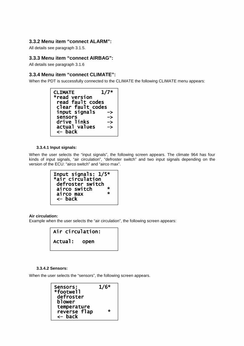
3.3.2 Menu item “connect ALARM”: All details see paragraph 3.1.5.
3.3.3 Menu item “connect AIRBAG”: All details see paragraph 3.1.6
3.3.4 Menu item “connect CLIMATE”: When the PDT is successfully connected to the CLIMATE the following CLIMATE menu appears:
3.3.4.1 Input signals:
When the user selects the “input signals”, the following screen appears. The climate 964 has four kinds of input signals, “air circulation”, “defroster switch” and two input signals depending on the version of the ECU: “airco switch” and “airco max”. Air circulation: Example when the user selects the “air circulation”, the following screen appears:
3.3.4.2 Sensors:
When the user selects the “sensors”, the following screen appears.
CLIMATE 1/7*CLIMATE 1/7*CLIMATE 1/7*CLIMATE 1/7* *read version*read version*read version*read version read fault codesread fault codesread fault codesread fault codes clear fault codesclear fault codesclear fault codesclear fault codes input signals input signals input signals input signals ––––>>>> sensors sensors sensors sensors ––––>>>> drive links drive links drive links drive links ––––>>>> actual values actual values actual values actual values ––––>>>> <<<<–––– backbackbackback
Input signals: 1/5*Input signals: 1/5*Input signals: 1/5*Input signals: 1/5* *air circulation*air circulation*air circulation*air circulation defroster switchdefroster switchdefroster switchdefroster switch airco switch airco switch airco switch airco switch **** airco max *airco max *airco max *airco max * <<<<–––– backbackbackback
Sensors: 1/6*Sensors: 1/6*Sensors: 1/6*Sensors: 1/6* *footwell*footwell*footwell*footwell defrosterdefrosterdefrosterdefroster blowerblowerblowerblower temperaturetemperaturetemperaturetemperature reverse flap *reverse flap *reverse flap *reverse flap * <<<<–––– backbackbackback
Air circulation:Air circulation:Air circulation:Air circulation: Actual:Actual:Actual:Actual: openopenopenopen
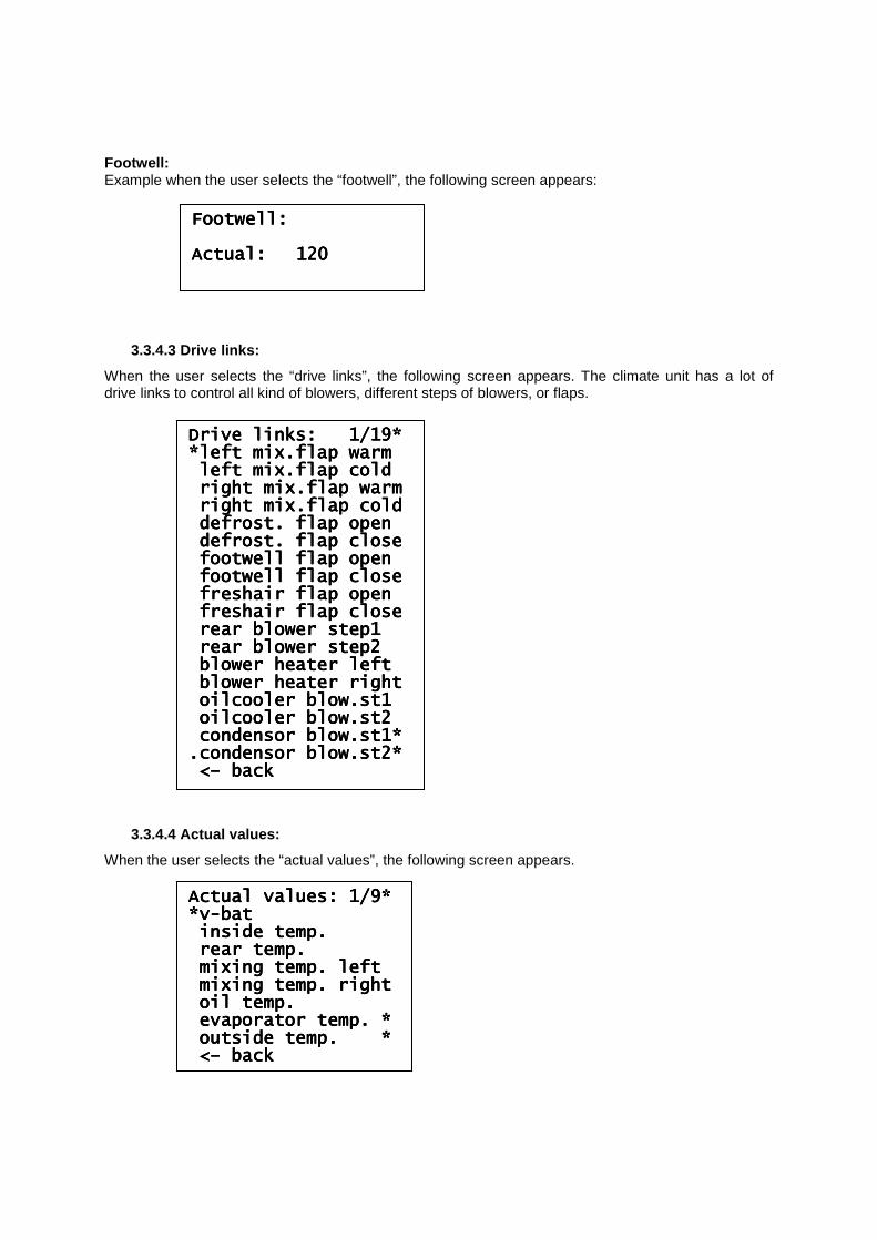
Footwell: Example when the user selects the “footwell”, the following screen appears:
3.3.4.3 Drive links:
When the user selects the “drive links”, the following screen appears. The climate unit has a lot of drive links to control all kind of blowers, different steps of blowers, or flaps.
3.3.4.4 Actual values:
When the user selects the “actual values”, the following screen appears.
Drive links: 1/19*Drive links: 1/19*Drive links: 1/19*Drive links: 1/19* *left mix.flap warm*left mix.flap warm*left mix.flap warm*left mix.flap warm left mix.flap coldleft mix.flap coldleft mix.flap coldleft mix.flap cold right mix.flap warmright mix.flap warmright mix.flap warmright mix.flap warm right mix.flap coldright mix.flap coldright mix.flap coldright mix.flap cold defrost. flap opendefrost. flap opendefrost. flap opendefrost. flap open defrosdefrosdefrosdefrost. flap closet. flap closet. flap closet. flap close footwell flap openfootwell flap openfootwell flap openfootwell flap open footwell flap closefootwell flap closefootwell flap closefootwell flap close freshair flap openfreshair flap openfreshair flap openfreshair flap open freshair flap closefreshair flap closefreshair flap closefreshair flap close rear blower step1rear blower step1rear blower step1rear blower step1 rear blower step2rear blower step2rear blower step2rear blower step2 blower heater leftblower heater leftblower heater leftblower heater left blower heater rightblower heater rightblower heater rightblower heater right oilcooler blow.st1oilcooler blow.st1oilcooler blow.st1oilcooler blow.st1 oilcooler blow.st2oilcooler blow.st2oilcooler blow.st2oilcooler blow.st2 condensor blow.st1*condensor blow.st1*condensor blow.st1*condensor blow.st1* .condensor blow.st2*.condensor blow.st2*.condensor blow.st2*.condensor blow.st2* <<<<–––– backbackbackback
Actual values: 1/9*Actual values: 1/9*Actual values: 1/9*Actual values: 1/9* *v*v*v*v----batbatbatbat inside temp.inside temp.inside temp.inside temp. rear temp.rear temp.rear temp.rear temp. mixing temp. leftmixing temp. leftmixing temp. leftmixing temp. left mixing temp. rightmixing temp. rightmixing temp. rightmixing temp. right oil temp.oil temp.oil temp.oil temp. evaporator temp. *evaporator temp. *evaporator temp. *evaporator temp. * outside temp. *outside temp. *outside temp. *outside temp. * <<<<–––– backbackbackback
Footwell:Footwell:Footwell:Footwell: Actual:Actual:Actual:Actual: 120120120120 ████████████████████████████████████████████████████████████████
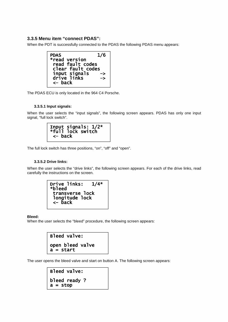
3.3.5 Menu item “connect PDAS”: When the PDT is successfully connected to the PDAS the following PDAS menu appears: The PDAS ECU is only located in the 964 C4 Porsche.
3.3.5.1 Input signals:
When the user selects the “input signals”, the following screen appears. PDAS has only one input signal, “full lock switch”. The full lock switch has three positions, “on”, “off” and “open”.
3.3.5.2 Drive links:
When the user selects the “drive links”, the following screen appears. For each of the drive links, read carefully the instructions on the screen. Bleed: When the user selects the “bleed” procedure, the following screen appears: The user opens the bleed valve and start on button A. The following screen appears:
PDAS 1/6 PDAS 1/6 PDAS 1/6 PDAS 1/6 *read version*read version*read version*read version read fault codesread fault codesread fault codesread fault codes clear fault codesclear fault codesclear fault codesclear fault codes input signals input signals input signals input signals ––––>>>> drive links drive links drive links drive links ––––>>>> <<<<–––– backbackbackback
Input signals: 1/2*Input signals: 1/2*Input signals: 1/2*Input signals: 1/2* *full lock switch*full lock switch*full lock switch*full lock switch <<<<–––– backbackbackback
Drive links: 1/4*Drive links: 1/4*Drive links: 1/4*Drive links: 1/4* *bleed*bleed*bleed*bleed transverse locktransverse locktransverse locktransverse lock longitude locklongitude locklongitude locklongitude lock <<<<–––– backbackbackback
Bleed valve:Bleed valve:Bleed valve:Bleed valve: open bleed valveopen bleed valveopen bleed valveopen bleed valve a = starta = starta = starta = start
Bleed valve:Bleed valve:Bleed valve:Bleed valve: bleed ready ?bleed ready ?bleed ready ?bleed ready ? a = stopa = stopa = stopa = stop
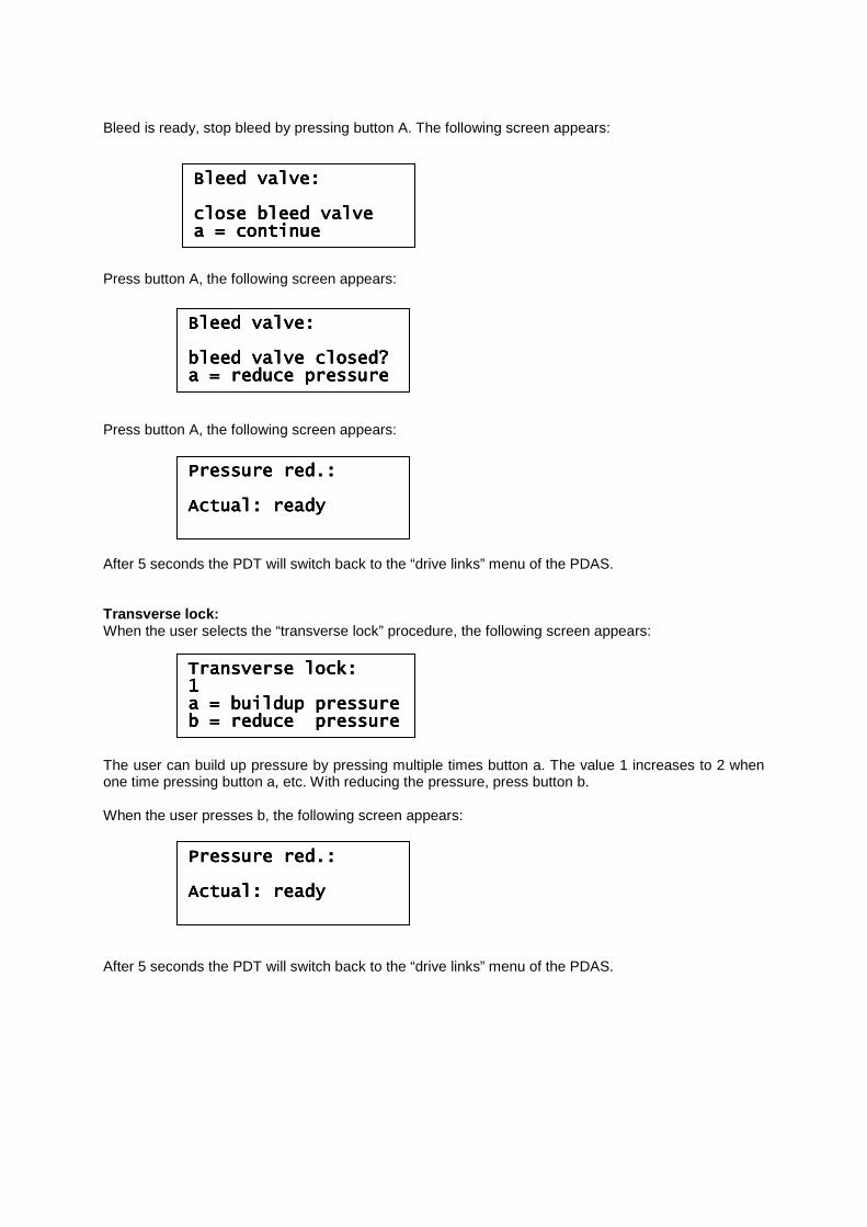
Bleed is ready, stop bleed by pressing button A. The following screen appears: Press button A, the following screen appears: Press button A, the following screen appears: After 5 seconds the PDT will switch back to the “drive links” menu of the PDAS. Transverse lock: When the user selects the “transverse lock” procedure, the following screen appears: The user can build up pressure by pressing multiple times button a. The value 1 increases to 2 when one time pressing button a, etc. With reducing the pressure, press button b. When the user presses b, the following screen appears: After 5 seconds the PDT will switch back to the “drive links” menu of the PDAS.
Bleed valve:Bleed valve:Bleed valve:Bleed valve: close bleed valveclose bleed valveclose bleed valveclose bleed valve a = continuea = continuea = continuea = continue
Bleed valve:Bleed valve:Bleed valve:Bleed valve: bleed valve closed?bleed valve closed?bleed valve closed?bleed valve closed? a = reduce pressurea = reduce pressurea = reduce pressurea = reduce pressure
Pressure red.:Pressure red.:Pressure red.:Pressure red.: Actual: readyActual: readyActual: readyActual: ready
TransTransTransTransverse lock:verse lock:verse lock:verse lock: 1111 a = buildup pressurea = buildup pressurea = buildup pressurea = buildup pressure b = reduce pressureb = reduce pressureb = reduce pressureb = reduce pressure
Pressure red.:Pressure red.:Pressure red.:Pressure red.: Actual: readyActual: readyActual: readyActual: ready
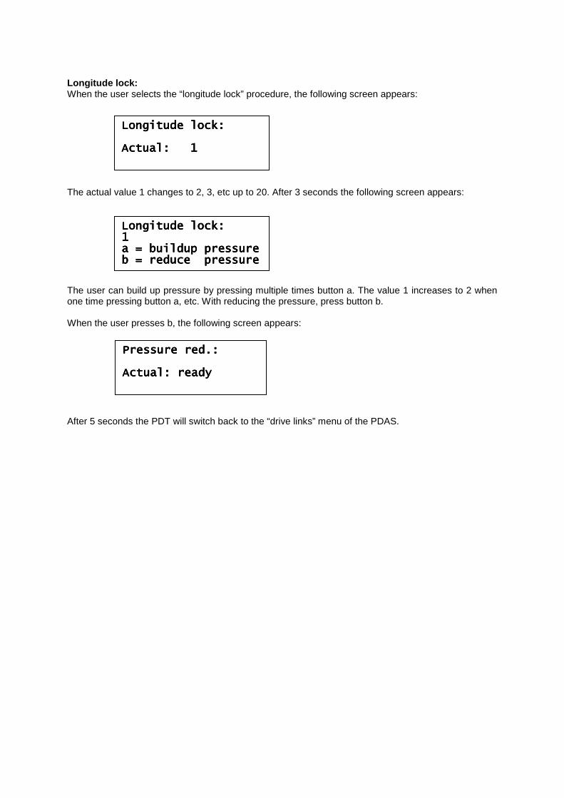
Longitude lock: When the user selects the “longitude lock” procedure, the following screen appears: The actual value 1 changes to 2, 3, etc up to 20. After 3 seconds the following screen appears: The user can build up pressure by pressing multiple times button a. The value 1 increases to 2 when one time pressing button a, etc. With reducing the pressure, press button b. When the user presses b, the following screen appears: After 5 seconds the PDT will switch back to the “drive links” menu of the PDAS.
Longitude lock:Longitude lock:Longitude lock:Longitude lock: Actual: 1Actual: 1Actual: 1Actual: 1
Longitude lock:Longitude lock:Longitude lock:Longitude lock: 1111 a = buildup pressurea = buildup pressurea = buildup pressurea = buildup pressure b = reduce pressureb = reduce pressureb = reduce pressureb = reduce pressure
Pressure red.:Pressure red.:Pressure red.:Pressure red.: Actual: readyActual: readyActual: readyActual: ready
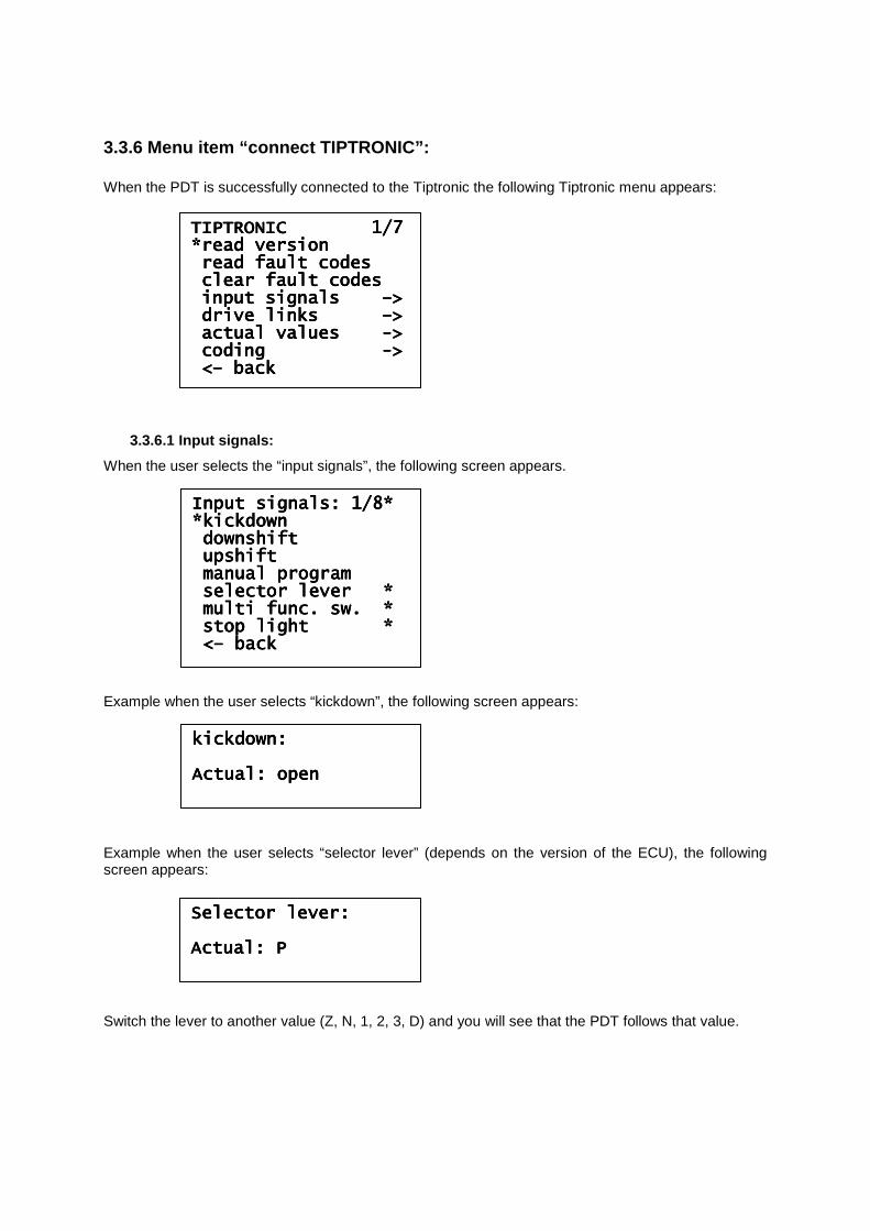
3.3.6 Menu item “connect TIPTRONIC”: When the PDT is successfully connected to the Tiptronic the following Tiptronic menu appears:
3.3.6.1 Input signals:
When the user selects the “input signals”, the following screen appears. Example when the user selects “kickdown”, the following screen appears: Example when the user selects “selector lever” (depends on the version of the ECU), the following screen appears: Switch the lever to another value (Z, N, 1, 2, 3, D) and you will see that the PDT follows that value.
TIPTRONIC 1/7 TIPTRONIC 1/7 TIPTRONIC 1/7 TIPTRONIC 1/7 *read version*read version*read version*read version read fault codesread fault codesread fault codesread fault codes clear fault codesclear fault codesclear fault codesclear fault codes input signals input signals input signals input signals ––––>>>> drive linkdrive linkdrive linkdrive links s s s ––––>>>> actual values actual values actual values actual values ---->>>> coding coding coding coding ---->>>> <<<<–––– backbackbackback
Input signals: 1/8*Input signals: 1/8*Input signals: 1/8*Input signals: 1/8* *kickdown*kickdown*kickdown*kickdown downshiftdownshiftdownshiftdownshift upshiftupshiftupshiftupshift manual programmanual programmanual programmanual program selector lever *selector lever *selector lever *selector lever * multi func. sw. *multi func. sw. *multi func. sw. *multi func. sw. * stop light *stop light *stop light *stop light * <<<<–––– backbackbackback
kickdown:kickdown:kickdown:kickdown: Actual: openActual: openActual: openActual: open
Selector lever:Selector lever:Selector lever:Selector lever: ActuActuActuActual: Pal: Pal: Pal: P
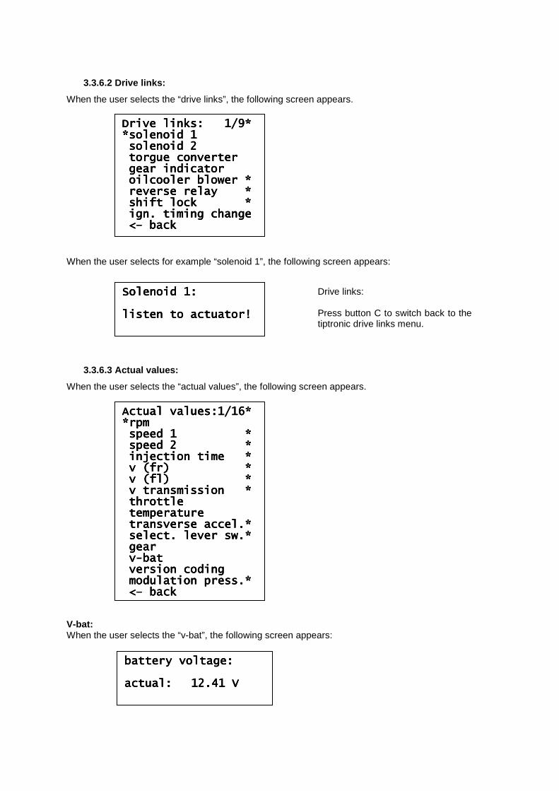
3.3.6.2 Drive links:
When the user selects the “drive links”, the following screen appears. When the user selects for example “solenoid 1”, the following screen appears:
3.3.6.3 Actual values:
When the user selects the “actual values”, the following screen appears. V-bat: When the user selects the “v-bat”, the following screen appears:
Drive links: 1/9*Drive links: 1/9*Drive links: 1/9*Drive links: 1/9* *solenoid 1*solenoid 1*solenoid 1*solenoid 1 solenoid 2solenoid 2solenoid 2solenoid 2 torgue convertorgue convertorgue convertorgue converterterterter gear indicatorgear indicatorgear indicatorgear indicator oilcooler blower *oilcooler blower *oilcooler blower *oilcooler blower * reverse relay *reverse relay *reverse relay *reverse relay * shift lock *shift lock *shift lock *shift lock * ign. timing changeign. timing changeign. timing changeign. timing change <<<<–––– backbackbackback
Actual values:1/16*Actual values:1/16*Actual values:1/16*Actual values:1/16* *rpm*rpm*rpm*rpm speed 1 *speed 1 *speed 1 *speed 1 * speed 2 *speed 2 *speed 2 *speed 2 * injection time *injection time *injection time *injection time * v (fr) *v (fr) *v (fr) *v (fr) * v (fl) *v (fl) *v (fl) *v (fl) * v transmission *v transmission *v transmission *v transmission * throttlethrottlethrottlethrottle temperaturetemperaturetemperaturetemperature transverse accel.*transverse accel.*transverse accel.*transverse accel.* select. lever sw.*select. lever sw.*select. lever sw.*select. lever sw.* geargeargeargear vvvv----batbatbatbat version codingversion codingversion codingversion coding modulation press.*modulation press.*modulation press.*modulation press.* <<<<–––– backbackbackback
Solenoid 1:Solenoid 1:Solenoid 1:Solenoid 1: listen to actuator!listen to actuator!listen to actuator!listen to actuator!
Drive links: Press button C to switch back to the tiptronic drive links menu.
battery voltage:battery voltage:battery voltage:battery voltage: actual:actual:actual:actual: 12.41 V12.41 V12.41 V12.41 V
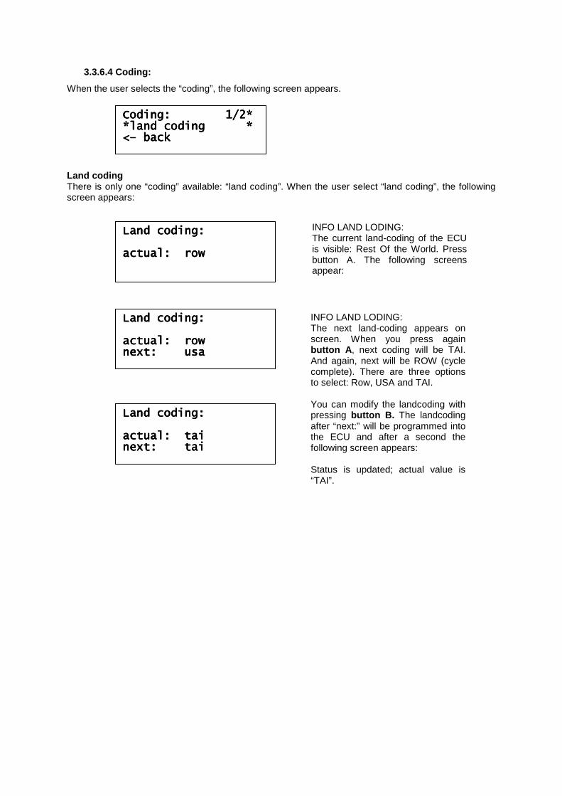
3.3.6.4 Coding:
When the user selects the “coding”, the following screen appears. Land coding There is only one “coding” available: “land coding”. When the user select “land coding”, the following screen appears:
Coding: 1/2*Coding: 1/2*Coding: 1/2*Coding: 1/2* *land coding **land coding **land coding **land coding * <<<<–––– backbackbackback
Land coding:Land coding:Land coding:Land coding: actual: rowactual: rowactual: rowactual: row
INFO LAND LODING: The current land-coding of the ECU is visible: Rest Of the World. Press button A. The following screens appear:
Land coding:Land coding:Land coding:Land coding: actual: rowactual: rowactual: rowactual: row next: usanext: usanext: usanext: usa
INFO LAND LODING: The next land-coding appears on screen. When you press again button A , next coding will be TAI. And again, next will be ROW (cycle complete). There are three options to select: Row, USA and TAI. You can modify the landcoding with pressing button B. The landcoding after “next:” will be programmed into the ECU and after a second the following screen appears: Status is updated; actual value is “TAI”.
Land coding:Land coding:Land coding:Land coding: actual: taiactual: taiactual: taiactual: tai next: tainext: tainext: tainext: tai
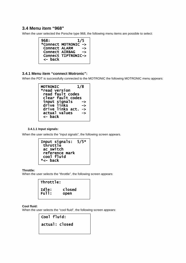
3.4 Menu item “968” When the user selected the Porsche type 968, the following menu items are possible to select:
3.4.1 Menu item “connect Motronic”: When the PDT is successfully connected to the MOTRONIC the following MOTRONIC menu appears:
3.4.1.1 Input signals:
When the user selects the “input signals”, the following screen appears. Throttle: When the user selects the “throttle”, the following screen appears: Cool fluid: When the user selects the “cool fluid”, the following screen appears:
968: 1/5 968: 1/5 968: 1/5 968: 1/5 *Connect MOTRONIC *Connect MOTRONIC *Connect MOTRONIC *Connect MOTRONIC ––––>>>> Connect ALARM Connect ALARM Connect ALARM Connect ALARM ––––>>>> Connect AIRBAG Connect AIRBAG Connect AIRBAG Connect AIRBAG ––––>>>> CCCConnect TIPTRONIConnect TIPTRONIConnect TIPTRONIConnect TIPTRONIC---->>>> <<<<–––– backbackbackback
MOTRONIC 1/8 MOTRONIC 1/8 MOTRONIC 1/8 MOTRONIC 1/8 *read version*read version*read version*read version read fault codesread fault codesread fault codesread fault codes clear fault codesclear fault codesclear fault codesclear fault codes input signals input signals input signals input signals ––––>>>> drive links drive links drive links drive links ––––>>>> drive links act. drive links act. drive links act. drive links act. ---->>>> actual values actual values actual values actual values ––––>>>> <<<<–––– backbackbackback
Input signals: 5/5*Input signals: 5/5*Input signals: 5/5*Input signals: 5/5* throttlethrottlethrottlethrottle ac switchac switchac switchac switch reference markreference markreference markreference mark cocococool fluidol fluidol fluidol fluid *<*<*<*<–––– backbackbackback
Throttle:Throttle:Throttle:Throttle: Idle:Idle:Idle:Idle: closedclosedclosedclosed Full:Full:Full:Full: openopenopenopen
Cool fluid:Cool fluid:Cool fluid:Cool fluid: actual: closedactual: closedactual: closedactual: closed
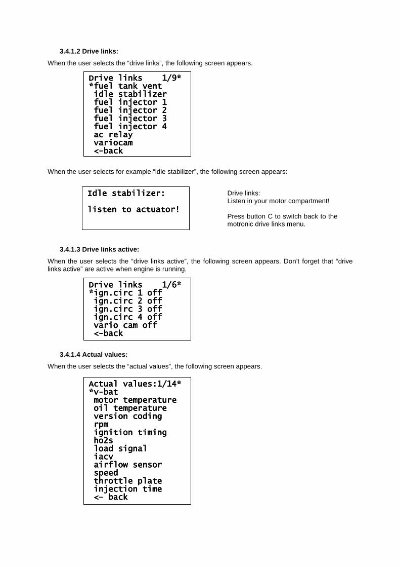
3.4.1.2 Drive links:
When the user selects the “drive links”, the following screen appears. When the user selects for example “idle stabilizer”, the following screen appears:
3.4.1.3 Drive links active:
When the user selects the “drive links active”, the following screen appears. Don’t forget that “drive links active” are active when engine is running.
3.4.1.4 Actual values:
When the user selects the “actual values”, the following screen appears.
Drive links 1/9*Drive links 1/9*Drive links 1/9*Drive links 1/9* *fuel tank vent*fuel tank vent*fuel tank vent*fuel tank vent idle stabilizeridle stabilizeridle stabilizeridle stabilizer fuel injector 1fuel injector 1fuel injector 1fuel injector 1 fuel injector 2fuel injector 2fuel injector 2fuel injector 2 fuel injector 3fuel injector 3fuel injector 3fuel injector 3 fuel injector 4fuel injector 4fuel injector 4fuel injector 4 ac relayac relayac relayac relay variocamvariocamvariocamvariocam <<<<----backbackbackback
Drive links 1/6*Drive links 1/6*Drive links 1/6*Drive links 1/6* *ign.circ 1 off*ign.circ 1 off*ign.circ 1 off*ign.circ 1 off ign.circ 2 offign.circ 2 offign.circ 2 offign.circ 2 off ign.circ 3 offign.circ 3 offign.circ 3 offign.circ 3 off ign.circ 4 offign.circ 4 offign.circ 4 offign.circ 4 off vario cam offvario cam offvario cam offvario cam off <<<<----backbackbackback
Actual values:1/14*Actual values:1/14*Actual values:1/14*Actual values:1/14* *v*v*v*v----batbatbatbat motor temperaturemotor temperaturemotor temperaturemotor temperature oil temperatureoil temperatureoil temperatureoil temperature version codingversion codingversion codingversion coding rpmrpmrpmrpm ignition timingignition timingignition timingignition timing ho2sho2sho2sho2s load signalload signalload signalload signal iacviacviacviacv airflow sensorairflow sensorairflow sensorairflow sensor speedspeedspeedspeed throttle platethrottle platethrottle platethrottle plate injection timeinjection timeinjection timeinjection time <<<<–––– backbackbackback
Idle stabilizer:Idle stabilizer:Idle stabilizer:Idle stabilizer: listen to aclisten to aclisten to aclisten to actuator!tuator!tuator!tuator!
Drive links: Listen in your motor compartment! Press button C to switch back to the motronic drive links menu.
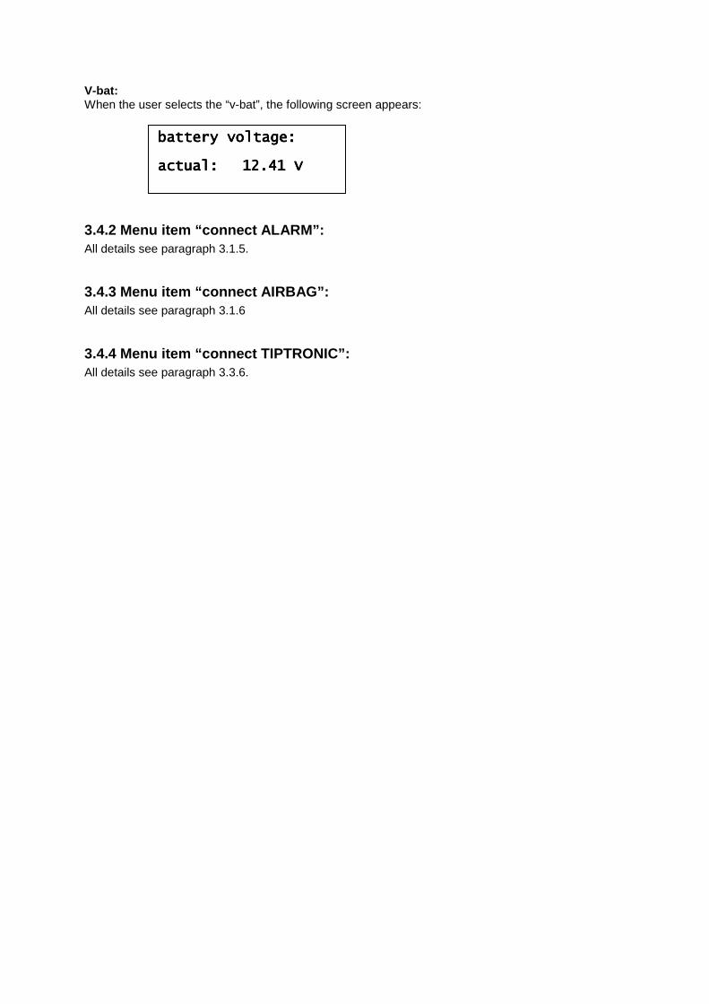
V-bat: When the user selects the “v-bat”, the following screen appears:
3.4.2 Menu item “connect ALARM”: All details see paragraph 3.1.5.
3.4.3 Menu item “connect AIRBAG”: All details see paragraph 3.1.6
3.4.4 Menu item “connect TIPTRONIC”: All details see paragraph 3.3.6.
battery voltage:battery voltage:battery voltage:battery voltage: actual:actual:actual:actual: 12.41 V12.41 V12.41 V12.41 V
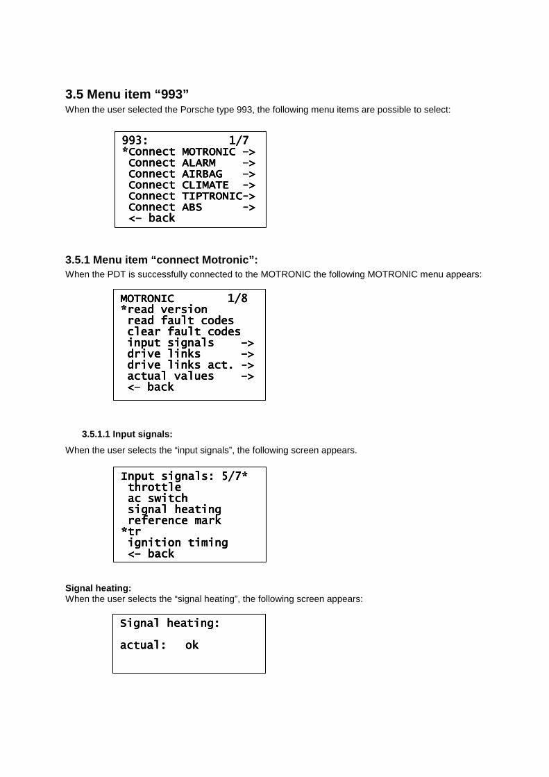
3.5 Menu item “993” When the user selected the Porsche type 993, the following menu items are possible to select:
3.5.1 Menu item “connect Motronic”: When the PDT is successfully connected to the MOTRONIC the following MOTRONIC menu appears:
3.5.1.1 Input signals:
When the user selects the “input signals”, the following screen appears. Signal heating: When the user selects the “signal heating”, the following screen appears:
993: 1/7 993: 1/7 993: 1/7 993: 1/7 *Connect MOTRONIC *Connect MOTRONIC *Connect MOTRONIC *Connect MOTRONIC ––––>>>> Connect ALARM Connect ALARM Connect ALARM Connect ALARM ––––>>>> Connect AIRBAG Connect AIRBAG Connect AIRBAG Connect AIRBAG ––––>>>> CoCoCoConnect CLIMATE nnect CLIMATE nnect CLIMATE nnect CLIMATE ---->>>> Connect TIPTRONICConnect TIPTRONICConnect TIPTRONICConnect TIPTRONIC---->>>> Connect ABS Connect ABS Connect ABS Connect ABS ---->>>> <<<<–––– backbackbackback
MOTRONIC 1/8 MOTRONIC 1/8 MOTRONIC 1/8 MOTRONIC 1/8 *read version*read version*read version*read version read fault codesread fault codesread fault codesread fault codes clear fault codesclear fault codesclear fault codesclear fault codes input signals input signals input signals input signals ––––>>>> drive links drive links drive links drive links ––––>>>> drive links act. drive links act. drive links act. drive links act. ---->>>> actual actual actual actual values values values values ––––>>>> <<<<–––– backbackbackback
Input signals: 5/7*Input signals: 5/7*Input signals: 5/7*Input signals: 5/7* throttlethrottlethrottlethrottle ac switchac switchac switchac switch signal heatingsignal heatingsignal heatingsignal heating reference markreference markreference markreference mark *tr*tr*tr*tr ignition timingignition timingignition timingignition timing <<<<–––– backbackbackback
Signal heating:Signal heating:Signal heating:Signal heating: actual:actual:actual:actual: okokokok
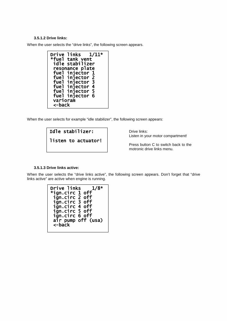
3.5.1.2 Drive links:
When the user selects the “drive links”, the following screen appears. When the user selects for example “idle stabilizer”, the following screen appears:
3.5.1.3 Drive links active:
When the user selects the “drive links active”, the following screen appears. Don’t forget that “drive links active” are active when engine is running.
Drive links 1/11*Drive links 1/11*Drive links 1/11*Drive links 1/11* *fuel tank vent*fuel tank vent*fuel tank vent*fuel tank vent idle stabilizeridle stabilizeridle stabilizeridle stabilizer resonance plateresonance plateresonance plateresonance plate fuel injector 1fuel injector 1fuel injector 1fuel injector 1 fuel injector 2fuel injector 2fuel injector 2fuel injector 2 fuel injector 3fuel injector 3fuel injector 3fuel injector 3 fuel infuel infuel infuel injector 4jector 4jector 4jector 4 fuel injector 5fuel injector 5fuel injector 5fuel injector 5 fuel injector 6fuel injector 6fuel injector 6fuel injector 6 varioramvarioramvarioramvarioram <<<<----backbackbackback
Drive links 1/8*Drive links 1/8*Drive links 1/8*Drive links 1/8* *ign.circ 1 off*ign.circ 1 off*ign.circ 1 off*ign.circ 1 off ign.circ 2 offign.circ 2 offign.circ 2 offign.circ 2 off ign.circ 3 offign.circ 3 offign.circ 3 offign.circ 3 off ign.circ 4 offign.circ 4 offign.circ 4 offign.circ 4 off ign.circ 5 offign.circ 5 offign.circ 5 offign.circ 5 off ign.circ 6 offign.circ 6 offign.circ 6 offign.circ 6 off air pump off (usa)air pump off (usa)air pump off (usa)air pump off (usa) <<<<----backbackbackback
Idle stabilizer:Idle stabilizer:Idle stabilizer:Idle stabilizer: listen to actuator!listen to actuator!listen to actuator!listen to actuator!
Drive links: Listen in your motor compartment! Press button C to switch back to the motronic drive links menu.
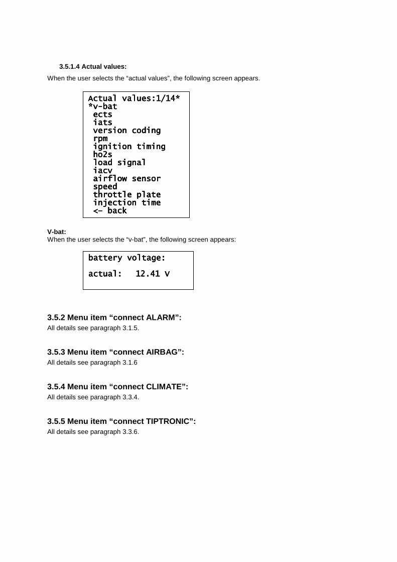
3.5.1.4 Actual values:
When the user selects the “actual values”, the following screen appears. V-bat: When the user selects the “v-bat”, the following screen appears:
3.5.2 Menu item “connect ALARM”: All details see paragraph 3.1.5.
3.5.3 Menu item “connect AIRBAG”: All details see paragraph 3.1.6
3.5.4 Menu item “connect CLIMATE”: All details see paragraph 3.3.4.
3.5.5 Menu item “connect TIPTRONIC”: All details see paragraph 3.3.6.
Actual values:1/14*Actual values:1/14*Actual values:1/14*Actual values:1/14* *v*v*v*v----batbatbatbat ectsectsectsects iatsiatsiatsiats version cversion cversion cversion codingodingodingoding rpmrpmrpmrpm ignition timingignition timingignition timingignition timing ho2sho2sho2sho2s load signalload signalload signalload signal iacviacviacviacv airflow sensorairflow sensorairflow sensorairflow sensor speedspeedspeedspeed throttle platethrottle platethrottle platethrottle plate injection timeinjection timeinjection timeinjection time <<<<–––– backbackbackback
battery voltage:battery voltage:battery voltage:battery voltage: actual:actual:actual:actual: 12.41 V12.41 V12.41 V12.41 V
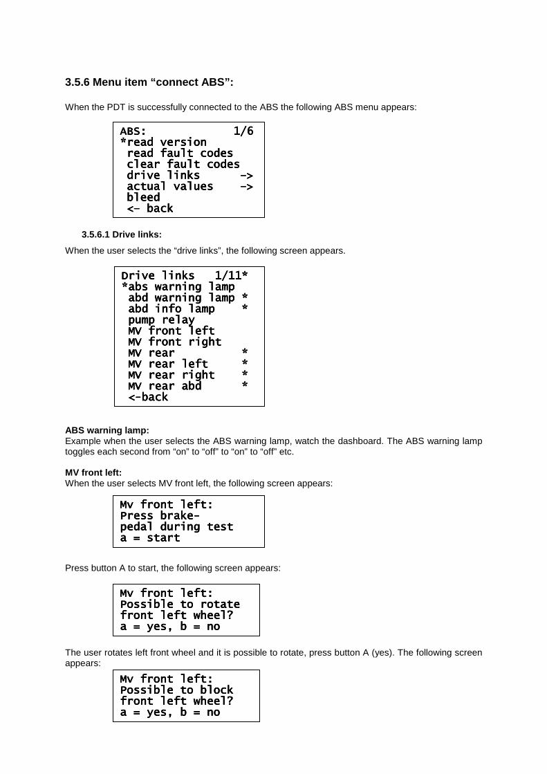
3.5.6 Menu item “connect ABS”: When the PDT is successfully connected to the ABS the following ABS menu appears:
3.5.6.1 Drive links:
When the user selects the “drive links”, the following screen appears. ABS warning lamp: Example when the user selects the ABS warning lamp, watch the dashboard. The ABS warning lamp toggles each second from “on” to “off” to “on” to “off” etc. MV front left: When the user selects MV front left, the following screen appears: Press button A to start, the following screen appears: The user rotates left front wheel and it is possible to rotate, press button A (yes). The following screen appears:
ABS: 1/6 ABS: 1/6 ABS: 1/6 ABS: 1/6 *read version*read version*read version*read version read fault codesread fault codesread fault codesread fault codes clear fault codesclear fault codesclear fault codesclear fault codes drive links drive links drive links drive links ––––>>>> actual values actual values actual values actual values ––––>>>> bleedbleedbleedbleed <<<<–––– backbackbackback
Drive Drive Drive Drive links 1/11*links 1/11*links 1/11*links 1/11* *abs warning lamp*abs warning lamp*abs warning lamp*abs warning lamp abd warning lamp *abd warning lamp *abd warning lamp *abd warning lamp * abd info lamp *abd info lamp *abd info lamp *abd info lamp * pump relaypump relaypump relaypump relay MV front leftMV front leftMV front leftMV front left MV front rightMV front rightMV front rightMV front right MV rear *MV rear *MV rear *MV rear * MV rear left *MV rear left *MV rear left *MV rear left * MV rear right *MV rear right *MV rear right *MV rear right * MV rear abd *MV rear abd *MV rear abd *MV rear abd * <<<<----backbackbackback
Mv front left:Mv front left:Mv front left:Mv front left: Press brakePress brakePress brakePress brake---- pedal during testpedal during testpedal during testpedal during test a = starta = starta = starta = start
Mv front left:Mv front left:Mv front left:Mv front left: Possible to rPossible to rPossible to rPossible to rotateotateotateotate front left wheel?front left wheel?front left wheel?front left wheel? a = yes, b = noa = yes, b = noa = yes, b = noa = yes, b = no
Mv front left:Mv front left:Mv front left:Mv front left: Possible to blockPossible to blockPossible to blockPossible to block front left wheel?front left wheel?front left wheel?front left wheel? a = yes, b = noa = yes, b = noa = yes, b = noa = yes, b = no
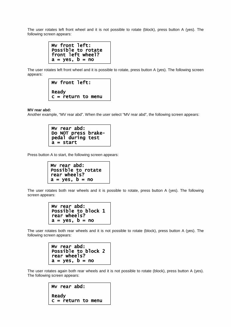
The user rotates left front wheel and it is not possible to rotate (block), press button A (yes). The following screen appears: The user rotates left front wheel and it is possible to rotate, press button A (yes). The following screen appears: MV rear abd: Another example, “MV rear abd”. When the user select “MV rear abd”, the following screen appears: Press button A to start, the following screen appears: The user rotates both rear wheels and it is possible to rotate, press button A (yes). The following screen appears: The user rotates both rear wheels and it is not possible to rotate (block), press button A (yes). The following screen appears: The user rotates again both rear wheels and it is not possible to rotate (block), press button A (yes). The following screen appears:
Mv front left:Mv front left:Mv front left:Mv front left: Possible to rotatePossible to rotatePossible to rotatePossible to rotate front left wheel?front left wheel?front left wheel?front left wheel? a = yes, b = noa = yes, b = noa = yes, b = noa = yes, b = no
Mv front left:Mv front left:Mv front left:Mv front left: ReadyReadyReadyReady c = return to menuc = return to menuc = return to menuc = return to menu
Mv rear abd:Mv rear abd:Mv rear abd:Mv rear abd: Do NOT press brakeDo NOT press brakeDo NOT press brakeDo NOT press brake---- pedpedpedpedal during testal during testal during testal during test a = starta = starta = starta = start
Mv rear abd:Mv rear abd:Mv rear abd:Mv rear abd: Possible to rotatePossible to rotatePossible to rotatePossible to rotate rear wheels?rear wheels?rear wheels?rear wheels? a = yes, b = noa = yes, b = noa = yes, b = noa = yes, b = no
Mv rear abd:Mv rear abd:Mv rear abd:Mv rear abd: Possible to block 1Possible to block 1Possible to block 1Possible to block 1 rear wheels?rear wheels?rear wheels?rear wheels? a = yes, b = noa = yes, b = noa = yes, b = noa = yes, b = no
Mv rear abd:Mv rear abd:Mv rear abd:Mv rear abd: Possible to block 2Possible to block 2Possible to block 2Possible to block 2 rear wheels?rear wheels?rear wheels?rear wheels? a = yes, b = noa = yes, b = noa = yes, b = noa = yes, b = no
Mv rear abd:Mv rear abd:Mv rear abd:Mv rear abd: ReadyReadyReadyReady c = return to menuc = return to menuc = return to menuc = return to menu
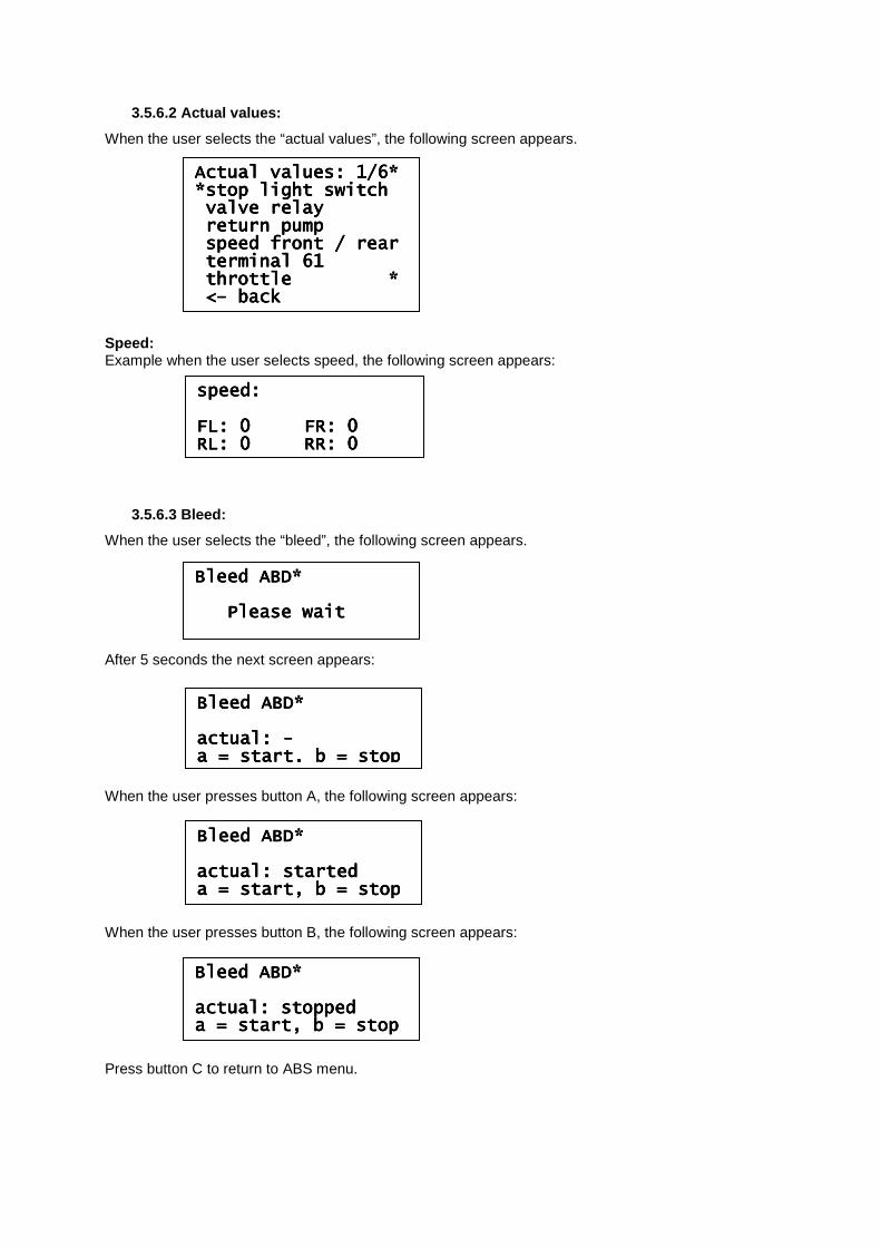
3.5.6.2 Actual values:
When the user selects the “actual values”, the following screen appears. Speed: Example when the user selects speed, the following screen appears:
3.5.6.3 Bleed:
When the user selects the “bleed”, the following screen appears. After 5 seconds the next screen appears: When the user presses button A, the following screen appears: When the user presses button B, the following screen appears: Press button C to return to ABS menu.
Actual values: 1/6*Actual values: 1/6*Actual values: 1/6*Actual values: 1/6* *stop light switch*stop light switch*stop light switch*stop light switch valve relayvalve relayvalve relayvalve relay return pumpreturn pumpreturn pumpreturn pump speed front / rearspeed front / rearspeed front / rearspeed front / rear terminal 61terminal 61terminal 61terminal 61 throttle *throttle *throttle *throttle * <<<<–––– backbackbackback
Bleed ABD*Bleed ABD*Bleed ABD*Bleed ABD* Please waitPlease waitPlease waitPlease wait
Bleed ABD*Bleed ABD*Bleed ABD*Bleed ABD* actual: actual: actual: actual: ---- a = start, b = stopa = start, b = stopa = start, b = stopa = start, b = stop
Bleed ABD*Bleed ABD*Bleed ABD*Bleed ABD* actual: startedactual: startedactual: startedactual: started a = start, b = stopa = start, b = stopa = start, b = stopa = start, b = stop
Bleed ABD*Bleed ABD*Bleed ABD*Bleed ABD* actual: stoppedactual: stoppedactual: stoppedactual: stopped a = start, b = stopa = start, b = stopa = start, b = stopa = start, b = stop
spspspspeed:eed:eed:eed: FL: 0 FR: 0FL: 0 FR: 0FL: 0 FR: 0FL: 0 FR: 0 RL: 0 RR: 0RL: 0 RR: 0RL: 0 RR: 0RL: 0 RR: 0
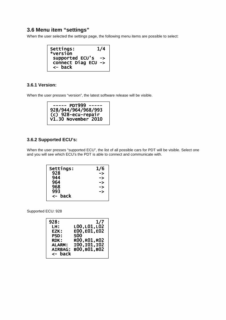
3.6 Menu item “settings” When the user selected the settings page, the following menu items are possible to select:
3.6.1 Version: When the user presses “version”, the latest software release will be visible.
3.6.2 Supported ECU’s: When the user presses “supported ECU”, the list of all possible cars for PDT will be visible. Select one and you will see which ECU’s the PDT is able to connect and communicate with. Supported ECU: 928
Settings: 1/4Settings: 1/4Settings: 1/4Settings: 1/4 *version*version*version*version supported ECU’s supported ECU’s supported ECU’s supported ECU’s ---->>>> connect Diag ECU connect Diag ECU connect Diag ECU connect Diag ECU ---->>>> <<<<–––– backbackbackback
-------------------- PDT999 PDT999 PDT999 PDT999 -------------------- 928/944/964/968/993 928/944/964/968/993 928/944/964/968/993 928/944/964/968/993 (c) 928(c) 928(c) 928(c) 928----ecuecuecuecu----repair repair repair repair V1.30 November 2010 V1.30 November 2010 V1.30 November 2010 V1.30 November 2010
Settings: Settings: Settings: Settings: 1/61/61/61/6 928 928 928 928 ---->>>> 944 944 944 944 ---->>>> 964 964 964 964 ---->>>> 968 968 968 968 ---->>>> 993 993 993 993 ---->>>> <<<<---- backbackbackback
928: 1/7928: 1/7928: 1/7928: 1/7 LH: L00,L01,L02LH: L00,L01,L02LH: L00,L01,L02LH: L00,L01,L02 EZK: E00,E01,E02EZK: E00,E01,E02EZK: E00,E01,E02EZK: E00,E01,E02 PSD: S00PSD: S00PSD: S00PSD: S00 RDK: R00,R01,R02RDK: R00,R01,R02RDK: R00,R01,R02RDK: R00,R01,R02 ALARM: I00,I01,I02ALARM: I00,I01,I02ALARM: I00,I01,I02ALARM: I00,I01,I02 AIRBAG: B00,B0AIRBAG: B00,B0AIRBAG: B00,B0AIRBAG: B00,B01,B021,B021,B021,B02 <<<<---- backbackbackback
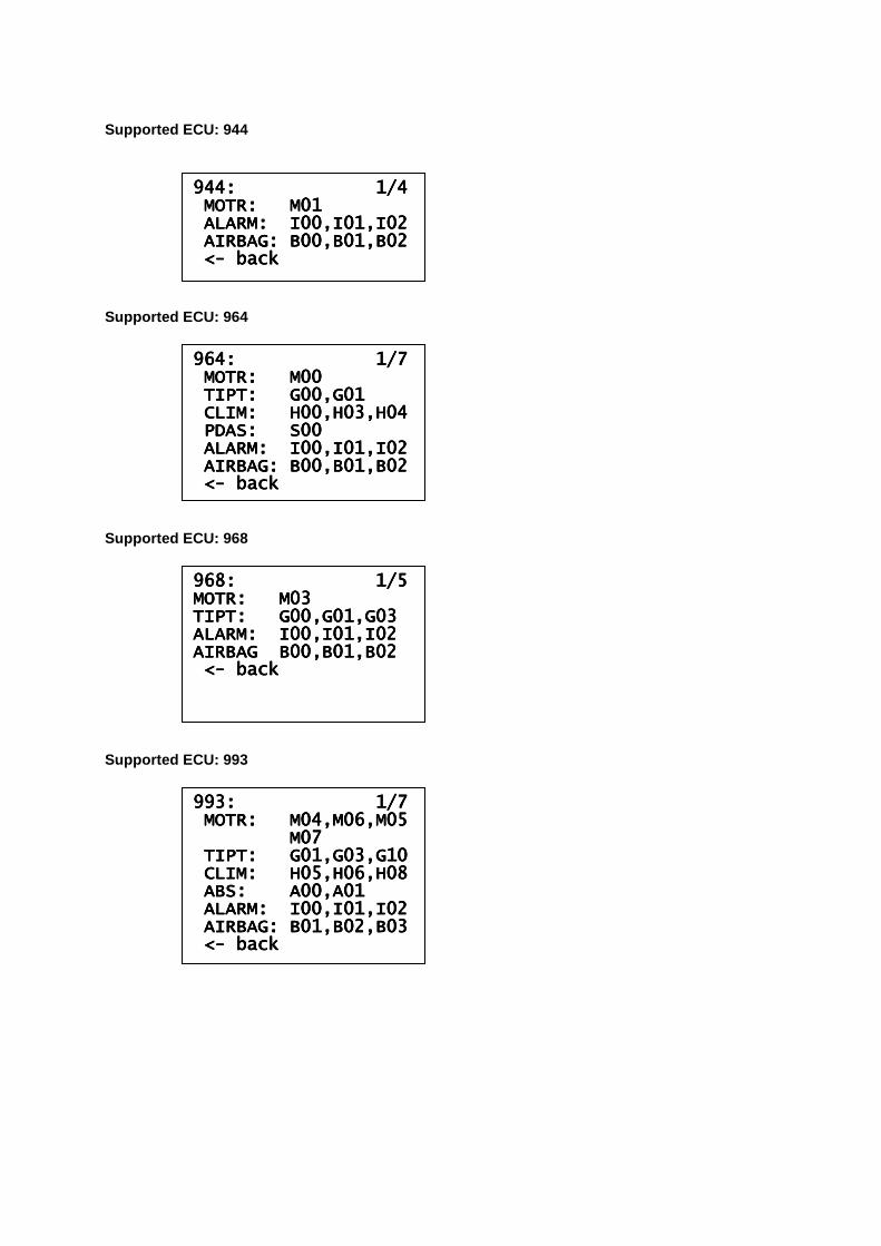
Supported ECU: 944 Supported ECU: 964 Supported ECU: 968 Supported ECU: 993
944: 1/4944: 1/4944: 1/4944: 1/4 MOTR: M01MOTR: M01MOTR: M01MOTR: M01 ALARM: I00,I01,I02ALARM: I00,I01,I02ALARM: I00,I01,I02ALARM: I00,I01,I02 AIRBAG: B00,B01,B02AIRBAG: B00,B01,B02AIRBAG: B00,B01,B02AIRBAG: B00,B01,B02 <<<<---- backbackbackback
964: 1/7964: 1/7964: 1/7964: 1/7 MOTR: M00MOTR: M00MOTR: M00MOTR: M00 TIPT: G00,G01TIPT: G00,G01TIPT: G00,G01TIPT: G00,G01 CLIM: H00,H03,H04CLIM: H00,H03,H04CLIM: H00,H03,H04CLIM: H00,H03,H04 PDAS: S00PDAS: S00PDAS: S00PDAS: S00 ALARM: I00,I01,I02ALARM: I00,I01,I02ALARM: I00,I01,I02ALARM: I00,I01,I02 AIRBAG: B00,B01,B02AIRBAG: B00,B01,B02AIRBAG: B00,B01,B02AIRBAG: B00,B01,B02 <<<<---- backbackbackback
968: 968: 968: 968: 1/51/51/51/5 MOTR: M03MOTR: M03MOTR: M03MOTR: M03 TIPT: G00,G01,G03TIPT: G00,G01,G03TIPT: G00,G01,G03TIPT: G00,G01,G03 ALARM: I00,I01,I02ALARM: I00,I01,I02ALARM: I00,I01,I02ALARM: I00,I01,I02 AIRBAG B00,B01,B02AIRBAG B00,B01,B02AIRBAG B00,B01,B02AIRBAG B00,B01,B02 <<<<---- backbackbackback
993: 1/7993: 1/7993: 1/7993: 1/7 MOTR: M04,M06,M05MOTR: M04,M06,M05MOTR: M04,M06,M05MOTR: M04,M06,M05 M07M07M07M07 TIPT: G01,G03,G10TIPT: G01,G03,G10TIPT: G01,G03,G10TIPT: G01,G03,G10 CLIM: H05,H06,H08CLIM: H05,H06,H08CLIM: H05,H06,H08CLIM: H05,H06,H08 ABS: A00,A01ABS: A00,A01ABS: A00,A01ABS: A00,A01 ALARM: I00,I01,I02ALARM: I00,I01,I02ALARM: I00,I01,I02ALARM: I00,I01,I02 AIRBAG: B01,B02,B03AIRBAG: B01,B02,B03AIRBAG: B01,B02,B03AIRBAG: B01,B02,B03 <<<<---- backbackbackback
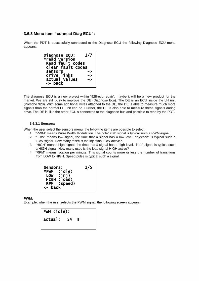
3.6.3 Menu item “connect Diag ECU”: When the PDT is successfully connected to the Diagnose ECU the following Diagnose ECU menu appears: The diagnose ECU is a new project within “928-ecu-repair”, maybe it will be a new product for the market. We are still busy to improve the DE (Diagnose Ecu). The DE is an ECU inside the LH unit (Porsche 928). With some additional wires attached to the DE, the DE is able to measure much more signals than the normal LH unit can do. Further, the DE is also able to measure these signals during drive. The DE is, like the other ECU’s connected to the diagnose bus and possible to read by the PDT.
3.6.3.1 Sensors:
When the user select the sensors menu, the following items are possible to select. 1. “PWM” means Pulse Width Modulation. The “idle” stab signal is typical such a PWM-signal. 2. “LOW” means low signal, the time that a signal has a low level. “injection” is typical such a
LOW signal. How many msec is the injection LOW active? 3. “HIGH” means high signal, the time that a signal has a high level. “load” signal is typical such
a HIGH signal. How many usec is the load signal HIGH active? 4. “RPM” means rotation per minute. This signal counts more or less the number of transitions
from LOW to HIGH. Speed pulse is typical such a signal. PWM: Example, when the user selects the PWM signal, the following screen appears:
DiagDiagDiagDiagnose ECU: 1/7 nose ECU: 1/7 nose ECU: 1/7 nose ECU: 1/7 *read version*read version*read version*read version Read fault codesRead fault codesRead fault codesRead fault codes clear fault codesclear fault codesclear fault codesclear fault codes sensors sensors sensors sensors ---->>>> drive links drive links drive links drive links ---->>>> actual values actual values actual values actual values ––––>>>> <<<<–––– backbackbackback
Sensors: 1/5Sensors: 1/5Sensors: 1/5Sensors: 1/5 *PWM (idle)*PWM (idle)*PWM (idle)*PWM (idle) LOW (inj)LOW (inj)LOW (inj)LOW (inj) HIGH (load)HIGH (load)HIGH (load)HIGH (load) RPM (speed)RPM (speed)RPM (speed)RPM (speed) <<<<---- backbackbackback
PWM (idle):PWM (idle):PWM (idle):PWM (idle): actual:actual:actual:actual: 54 %54 %54 %54 %
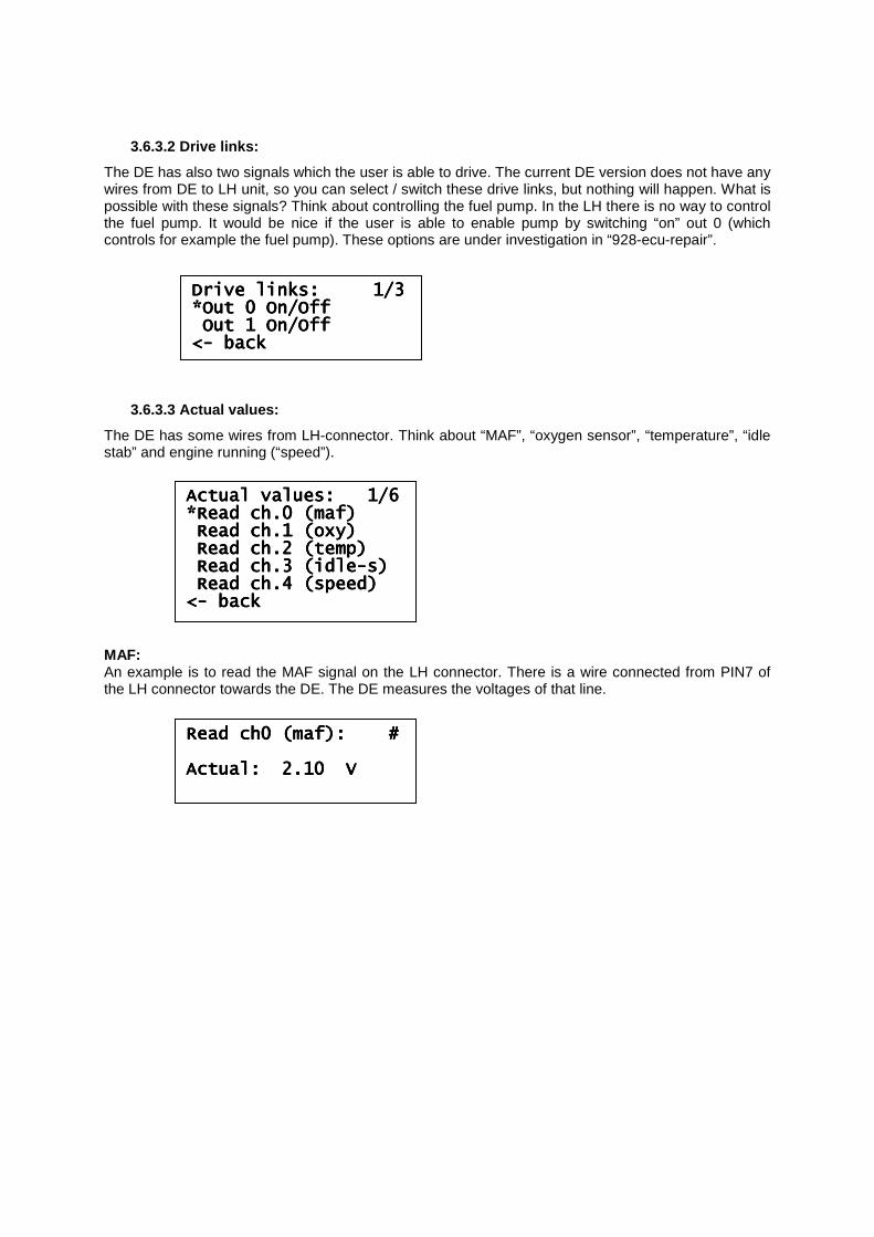
3.6.3.2 Drive links:
The DE has also two signals which the user is able to drive. The current DE version does not have any wires from DE to LH unit, so you can select / switch these drive links, but nothing will happen. What is possible with these signals? Think about controlling the fuel pump. In the LH there is no way to control the fuel pump. It would be nice if the user is able to enable pump by switching “on” out 0 (which controls for example the fuel pump). These options are under investigation in “928-ecu-repair”.
3.6.3.3 Actual values:
The DE has some wires from LH-connector. Think about “MAF”, “oxygen sensor”, “temperature”, “idle stab” and engine running (“speed”). MAF: An example is to read the MAF signal on the LH connector. There is a wire connected from PIN7 of the LH connector towards the DE. The DE measures the voltages of that line.
Actual values: 1/6Actual values: 1/6Actual values: 1/6Actual values: 1/6 *Read ch.0 (maf)*Read ch.0 (maf)*Read ch.0 (maf)*Read ch.0 (maf) Read ch.1 (oxy)Read ch.1 (oxy)Read ch.1 (oxy)Read ch.1 (oxy) Read ch.2 (temp)Read ch.2 (temp)Read ch.2 (temp)Read ch.2 (temp) Read ch.3 (idleRead ch.3 (idleRead ch.3 (idleRead ch.3 (idle----s)s)s)s) Read ch.4 (speed)Read ch.4 (speed)Read ch.4 (speed)Read ch.4 (speed) <<<<---- backbackbackback
Drive links: 1/3Drive links: 1/3Drive links: 1/3Drive links: 1/3 *Out 0 On/Off*Out 0 On/Off*Out 0 On/Off*Out 0 On/Off Out 1 On/OffOut 1 On/OffOut 1 On/OffOut 1 On/Off <<<<---- backbackbackback
Read ch0 (maf): #Read ch0 (maf): #Read ch0 (maf): #Read ch0 (maf): # Actual: Actual: Actual: Actual: 2.10 V2.10 V2.10 V2.10 V