Embed Size (px)
Citation preview

Document No: 710059 Issue Date: 21-Nov-2014 Revision: A Page: 1 of 13
This document and all copies are the property of Power Climber. All dimensions and data are indicative only. The user must ensure that the equipment complies with local rules and regulations.
Manufactured by: POWER CLIMBER Phone: (800) 560-CLIMB (2546) 365 Upland Drive Fax: (866) 470-8722 Seattle, WA 98188 Email: [email protected] Website: PowerClimber.com
USER MANUAL
POWER CLIMBER POWERMOD PLATFORM
Phone: (800) 560-CLIMB (2546) Email: [email protected] Fax: (866) 470-8722 Website: PowerClimber.com
This document and all copies are the property of Power Climber. All dimensions and data are indicative only. The user must ensure that the equipment complies with local rules and regulations.
Document No: 710059 Issue Date: 21-Nov-2014 Revision: A Page: 2 of 13
Table of Contents
Overview ................................................................................................. 3
Exploded View of Platform .....................................................................................3
Dimensions............................................................................................. 4
Safety ...................................................................................................... 5
Check Before Every Use .........................................................................................5
Cautions....................................................................................................................5
Load Capacity and Configuration......................................................... 6
Platform with End Frames and A-frame Stirrups .................................................6
Platform with Walk-thru Stirrups ...........................................................................6
Assembly Instructions........................................................................... 7
Platform with A-frame Stirrups ..............................................................................7
Platform with Walk-thru Stirrups ...........................................................................8
Code of Safe Practices for Adjustable Suspended Scaffolds............ 9

Phone: (800) 560-CLIMB (2546) Email: [email protected] Fax: (866) 470-8722 Website: PowerClimber.com
This document and all copies are the property of Power Climber. All dimensions and data are indicative only. The user must ensure that the equipment complies with local rules and regulations.
Document No: 710059 Issue Date: 21-Nov-2014 Revision: A Page: 3 of 13
Overview The modular design of the POWER CLIMBER POWERMOD PLATFORM allows you to modify the configuration of components to obtain the platform length required.
Exploded View of Platform
Item Description Part No. Item Description Part No.
1 SIDE FRAME; 1 METER 710306-1 5 GUARD RAIL POST 710024-1
SIDE FRAME; 2 METERS 710307-1 6 GUARD RAIL; 1 METER 710023-1
SIDE FRAME; 3 METERS 710308-1 GUARD RAIL; 2 METERS 710022-1
2 DECK; 1 METER 709996-1 GUARD RAIL; 3 METERS 710000-1
DECK; 2 METERS 709995-1 7 CASTER ASSEMBLY 710026-1
DECK; 3 METERS 709994-1 8 QUICK PIN 710029-1
3 U-FRAME 709992-1 9 GUARD RAIL; END 709991-1
4 END STIRRUP W/ A-FRAME 710311-1 10 ROLLER BUMPER 710025-1
8
3
4

Phone: (800) 560-CLIMB (2546) Email: [email protected] Fax: (866) 470-8722 Website: PowerClimber.com
This document and all copies are the property of Power Climber. All dimensions and data are indicative only. The user must ensure that the equipment complies with local rules and regulations.
Document No: 710059 Issue Date: 21-Nov-2014 Revision: A Page: 4 of 13
Dimensions 4-foot (1-meter) Section 7-foot (2-meter) Section 10-foot (3-meter) Section
Walk-Thru Stirrup Part No. 8-0234
End Frame Part No. 702056-1
A-frame Part No. 2-731
End Stirrup Assembly Part No. 710311-1 (includes A-frame & hardware)
3’ x 3”
6’ x 6”
9’ x 9”
Phone: (800) 560-CLIMB (2546) Email: [email protected] Fax: (866) 470-8722 Website: PowerClimber.com
This document and all copies are the property of Power Climber. All dimensions and data are indicative only. The user must ensure that the equipment complies with local rules and regulations.
Document No: 710059 Issue Date: 21-Nov-2014 Revision: A Page: 5 of 13
Safety Check Before Every Use
1. All pins must be in the horizontal (closed) position. 2. Condition of the quick pins:
Pressure in horizontal (closed) position Condition of the spring and spring holder
3. All holes in the side frames, end frames, U-frames, and stirrups. 4. Floor retainers.
The cable retainers of the power supply must be hooked onto the mid rail or cross braces. Wind restrictions at 12m/s (25mph). Cautions
1. Before using, check all parts for proper function and damage to component parts. Do not use a damaged or improperly functioning platform.
2. A platform exposed to excessive heat, as in the case of fire, should be immediately removed from service and destroyed due to loss of structural strength.
3. Do not permit oil, grease, or slippery material to accumulate on surfaces.
4. Do not use the product if the decking surface is damaged.
5. The total combined weight of all workers and materiel should not exceed the rated working load. Do not overload.
6. Make sure the working or standing surface of the platform is level.
7. Support platform ends with either end frames with A-frame stirrups or walk-thru stirrups per manufacturer's instructions.
8. Use of guard rails is required by local, state, and federal regulations.
9. Do not allow unstable objects, such as barrels, boxes, loose bricks, tools, or debris to accumulate on the work surface.
10. Do not use a ladder on platform. Never climb onto a stage from a ladder unless the stage and ladder are secured from movement in all directions. Do not apply impact loads to a platform. Never attempt to straighten a deformed side rail or decking member.
11. Do not use acids or other corrosive substances on a plank or platform without consulting the platform manufacturer for specific instructions.
12. Do not use a platform near electrical circuits.
13. Before using, refer to manufacturer's instructions.

Phone: (800) 560-CLIMB (2546) Email: [email protected] Fax: (866) 470-8722 Website: PowerClimber.com
This document and all copies are the property of Power Climber. All dimensions and data are indicative only. The user must ensure that the equipment complies with local rules and regulations.
Document No: 710059 Issue Date: 21-Nov-2014 Revision: A Page: 6 of 13
Load Capacity and Configuration The following tables include only configurations that have been tested and classified by UL. Platform sections -10-10-10- in feet (-3-3-3- in meters) may be replaced by -7-7- in feet (-2-2- in meters) as long as the maximum number of sections for the selected Rated Working Load and total platform length is not exceeded.
Platform with End Frames and A-frame Stirrups Total platform
length Platform configuration
Total platform weight
Rated working load
Ft/inch Meter In sections (ft) In sections (m) Lbs Kg Lbs Kg
Maximum number of sections
3′ 3″ 1 1 1 225 102 2000 909 1 6′ 6″ 2 7 2 297 135 2000 909 2 9′ 9″ 3 10 3 337 153 2000 909 2
13′ 6″ 4 7-7 2-2 422 192 2000 909 2 16′ 6″ 5 10-7 3-2 464 211 2000 909 2 19′ 6″ 6 10-10 3-3 504 229 2000 909 2 23′ 3″ 7 7-10-7 2-3-2 590 268 1500 682 3 26′ 3″ 8 10-7-10 3-2-3 631 287 1500 682 3 29′ 3″ 9 10-10-10 3-3-3 671 305 1000 455 4
33′ 10 10-7-7-10 3-2-2-3 757 344 1000 455 4 36′ 11 10-10-7-10 3-3-2-3 799 363 1000 455 4 39′ 12 10-10-10-10 3-3-3-3 838 381 1000 455 4
42′ 9″ 13 10-10-7-7-10 3-3-2-2-3 924 420 750 341 5 45′ 9″ 14 10-10-7-10-10 3-3-2-3-3 966 439 750 341 5 48′ 9″ 15 10-10-10-10-10 3-3-3-3-3 1005 457 750 341 5
Platform with Walk-thru Stirrups
Total platform length
Wire rope distance Platform configuration Total platform
weight Rated working load
Ft/inch Meter Ft/inch Meter In sections (ft) In sections (m) Lbs Kg Lbs Kg
Maximum number of sections
30′ 9″ 9 23′ 3″ 7 10-10-10* 3-3-3‡ 1001 455 1000 455 5
33′ 9″ 10 26′ 3″ 8 10-7-7-10* 3-2-2-3‡ 1087 494 1000 455 5
36′ 9″ 11 29′ 3″ 9 10-7-10-10* 3-2-3-3‡ 1129 513 1000 455 5
40′ 6″ 12 33′ 10 10-10-10-10* 3-3-3-3‡ 1168 531 1000 455 5
43′ 6″ 13 36′ 11 10-10-7-7-10* 3-3-2-2-3‡ 1254 570 1000 455 5
46′ 6″ 14 39′ 12 10-10-7-10-10* 3-3-2-3-3‡ 1296 589 1000 455 5
50′ 3″ 15 42′ 9″ 13 10-10-10-10-10* 3-3-3-3-3‡ 1335 607 750 341 7
53′ 3″ 16 45′ 9″ 14 10-10-7-7-10-10* 3-3-2-2-3-3‡ 1421 646 750 341 7
56′ 3″ 17 48′ 9″ 15 10-10-10-7-10-10* 3-3-3-2-3-3‡ 1463 665 750 341 7
46′ 6″ 14 33′-39′ 10-12 10-10-7-10-10** 3-3-2-3-3§ 1296 589 750 341 7
49′ 6″ 15 36′-42′ 9″ 11-13 10-10-10-10-10** 3-3-3-3-3§ 1335 607 750 341 7
52′ 3″ 16 39′-45′ 9″ 12-14 10-10-7-7-10-10** 3-3-2-2-3-3§ 1421 646 750 341 7
56′ 3″ 17 42′ 9″-48′ 9″ 13-15 10-10-10-7-10-10** 3-3-3-2-3-3§ 1463 665 750 341 7
59′ 3″ 18 45′ 9″ 14 10-10-10-10-10-10† 3-3-3-3-3-3# 1503 683 750 341 7
62′ 3″ 19 48′ 9″ 15 10-10-10-7-7-10-10† 3-3-3-2-2-3-3# 1586 721 750 341 7
* Outer 3-meter sections include 3′ 3″ cantilevered sections. ** Outer 7′ sections include cantilevered sections of between 3′ and 7′. † Outer 10′ sections include 7′ cantilevered sections. ‡ Outer 3-meter sections include 1-meter cantilevered sections. § Outer 3-meter sections include cantilevered sections of between 1 and 2 meters. # Outer 3-meter sections include 2-meter cantilevered sections. Note: The tables above assume that 2 powered hoists will be used. Total platform weight does NOT include weight of hoists, materiel, or workers. Rated working load must be evenly distributed on platform. For information about configurations not listed here, please consult your Power Climber dealer.
Phone: (800) 560-CLIMB (2546) Email: [email protected] Fax: (866) 470-8722 Website: PowerClimber.com
This document and all copies are the property of Power Climber. All dimensions and data are indicative only. The user must ensure that the equipment complies with local rules and regulations.
Document No: 710059 Issue Date: 21-Nov-2014 Revision: A Page: 7 of 13
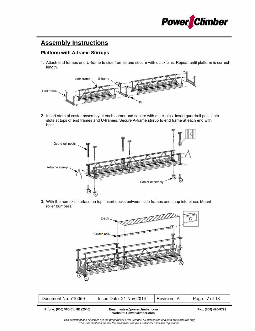
Assembly Instructions
Platform with A-frame Stirrups 1. Attach end frames and U-frame to side frames and secure with quick pins. Repeat until platform is correct
length.
Detail A
2. Insert stem of caster assembly at each corner and secure with quick pins. Insert guardrail posts into slots at tops of end frames and U-frames. Secure A-frame stirrup to end frame at each end with bolts.
End frame
Pin
Side frame
Guard rail posts
Caster assembly
3. With the non-skid surface on top, insert decks between side frames and snap into place. Mount roller bumpers.
Deck
Guard rail
A-frame stirrup
U-frame
Phone: (800) 560-CLIMB (2546) Email: [email protected] Fax: (866) 470-8722 Website: PowerClimber.com
This document and all copies are the property of Power Climber. All dimensions and data are indicative only. The user must ensure that the equipment complies with local rules and regulations.
Document No: 710059 Issue Date: 21-Nov-2014 Revision: A Page: 8 of 13
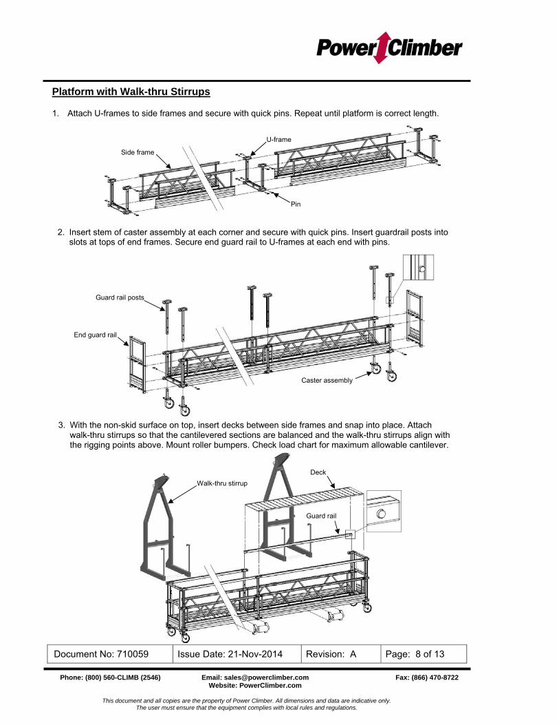
Platform with Walk-thru Stirrups 1. Attach U-frames to side frames and secure with quick pins. Repeat until platform is correct length.
Deck
Guard rail
Walk-thru stirrup
Guard rail posts
End guard rail
Caster assembly
Pin
Side frame
U-frame
2. Insert stem of caster assembly at each corner and secure with quick pins. Insert guardrail posts into slots at tops of end frames. Secure end guard rail to U-frames at each end with pins.
3. With the non-skid surface on top, insert decks between side frames and snap into place. Attach walk-thru stirrups so that the cantilevered sections are balanced and the walk-thru stirrups align with the rigging points above. Mount roller bumpers. Check load chart for maximum allowable cantilever.

Phone: (800) 560-CLIMB (2546) Email: [email protected] Fax: (866) 470-8722 Website: PowerClimber.com
This document and all copies are the property of Power Climber. All dimensions and data are indicative only. The user must ensure that the equipment complies with local rules and regulations.
Document No: 710059 Issue Date: 21-Nov-2014 Revision: A Page: 9 of 13
Code of Safe Practices for Adjustable Suspended Scaffolds
CO-DEVELOPED BY THE SCAFFOLDING, SHORING & FORMING INSTITUTE (SSFI) and THE SCAFFOLD AND ACCESS INDUSTRY ASSOCIATION, INC. (SAIA)
It shall be the responsibility of all users to read and comply with the following common sense guidelines which are designed to promote safety in the erecting, dismantling and use of adjustable suspended scaffolds. These guidelines do not purport to be all-inclusive nor to supplant or replace other additional safety and precautionary measures. If these guidelines conflict with any local, provincial, state, federal or other government regulations, the regulations shall supersede these guidelines and it shall be the responsibility of each user to comply therewith.
I. GENERAL GUIDELINES
A. POST THESE SAFE PRACTICES in a conspicuous place. Be sure that all persons who erect, use, relocate, or dismantle adjustable suspended scaffold systems are fully aware of them. Use them in tool box safety meetings.
B. FOLLOW ALL EQUIPMENT MANUFACTURER’S RECOMMENDATIONS as well as all local, provincial, state and federal codes, ordinances and regulations relating to adjustable suspended scaffold systems.
C. SURVEY THE JOB SITE. A competent person shall survey the job site for hazards such as exposed electrical wires, obstructions and, unguarded roof edges or openings.
D. INSPECT ALL EQUIPMENT BEFORE EACH USE. Never use any equipment that is damaged or defective in any way. Mark it or tag it as damaged or defective and remove it from the job site.
E. ERECT AND DISMANTLE ADJUSTABLE SUSPENDED SCAFFOLD EQUIPMENT in accordance with the design and/or manufacturer’s recommendations.
F. DO NOT ERECT, DISMANTLE OR ALTER ADJUSTABLE SUSPENDED SCAFFOLD SYSTEMS except under the supervision of a competent person.
G. DO NOT ABUSE OR MISUSE ADJUSTABLE SUSPENDED SCAFFOLD EQUIPMENT. Never overload any equipment.
H. ERECTED ADJUSTABLE SUSPENDED SCAFFOLDS ARE TO BE INSPECTED REGULARLY by the user to be sure that they are maintained in a safe condition. Stop work and report any unsafe condition to your supervisor.
I. NEVER TAKE CHANCES! IF IN DOUBT REGARDING THE SAFETY OR USE OF ADJUSTABLE SUSPENDED SCAFFOLDS, CONSULT A QUALIFIED PERSON.
J. NEVER USE ADJUSTABLE SUSPENDED SCAFFOLD EQUIPMENT FOR PURPOSES FOR WHICH IT WAS NOT INTENDED.
Phone: (800) 560-CLIMB (2546) Email: [email protected] Fax: (866) 470-8722 Website: PowerClimber.com
This document and all copies are the property of Power Climber. All dimensions and data are indicative only. The user must ensure that the equipment complies with local rules and regulations.
Document No: 710059 Issue Date: 21-Nov-2014 Revision: A Page: 10 of 13
K. A COMPETENT PERSON SHALL CONSIDER STOPPING WORK WHEN WIND SPEED EXCEEDS 25 MPH FOR 2-POINT ADJUSTABLE SUSPENDED SCAFFOLDS OR 20 MPH FOR SINGLE POINT SUSPENSION. If materials on a platform create a sail effect, stopping work at lower wind speeds must be considered.
L. ADJUSTABLE SUSPENDED SCAFFOLD SYSTEMS are to be installed and used in accordance with the manufacturer’s recommended procedures.
M. ADJUSTABLE SUSPENDED PLATFORMS MUST NEVER BE OPERATED NEAR LIVE POWER LINES unless proper precautions are taken. Contact the power service provider for advice.
N. ALWAYS UTILIZE FALL ARREST EQUIPMENT when working on adjustable suspended scaffolds or when working near unguarded edges.
O. DO NOT WORK FROM, INSTALL OR MOVE ADJUSTABLE SUSPENDED SCAFFOLDS if you are sick or impaired in any way.
P. DO NOT WORK ON ADJUSTABLE SUSPENDED SCAFFOLDS when under the influence of alcohol or drugs.
Q. DEBRIS SHOULD NOT BE STORED OR ALLOWED TO ACCUMULATE ON A PLATFORM.
R. INDEPENDENT ADJUSTABLE SUSPENDED SCAFFOLDS ARE TO BE POSITIONED SO AS TO AVOID OVERLAPPING OR POSSIBLE INTERFERENCE FROM ANOTHER SCAFFOLD.
II. GUIDELINES FRO ERECTION AND USE OF ADJUSTABLE SUSPENDED SCAFFOLD SYSTEMS
A. RIGGING:
1. UTILIZE FALL PROTECTION EQUIPMENT when rigging near unguarded edges.
2. SUPPORTING DEVICES must be capable of supporting the hoist rated load with a safety factor of 4.
3. ALL OVERHEAD RIGGING must be secured from unwanted movement in any direction.
4. COUNTERWEIGHTS USED WITH OUTRIGGER BEAMS must be of a non-flowable material and must be secured to the beam to prevent accidental displacement.
5. OUTRIGGER BEAMS THAT DO NOT USE COUNTERWEIGHTS must be installed and secured to the roof structure with bolts or other direct connections. Direct connections shall be evaluated by a competent person.
6. TIE BACK ALL TRANSPORTABLE RIGGING DEVICES. Tieback shall be equivalent in strength to the suspension ropes.
7. INSTALL TIEBACKS AT RIGHT ANGLES TO THE FACE OF THE BUILDING and secure them without slack, to a suitable anchor capable of supporting the hoist rated load with a safety factor of 4.
Phone: (800) 560-CLIMB (2546) Email: [email protected] Fax: (866) 470-8722 Website: PowerClimber.com
This document and all copies are the property of Power Climber. All dimensions and data are indicative only. The user must ensure that the equipment complies with local rules and regulations.
Document No: 710059 Issue Date: 21-Nov-2014 Revision: A Page: 11 of 13
8. IN THE EVENT THAT TIEBACKS CANNOT BE INSTALLED AT RIGHT ANGLES, two tiebacks at opposing angles must be used to prevent movement.
9. RIG AND USE HOISTING MACHINES DIRECTLY UNDER THEIR SUSPENSION POINTS to prevent movement or side loading.
B. WIRE ROPE AND HARDWARE:
1. USE ONLY WIRE ROPE AND ATTACHMENTS specified by the hoisting machine manufacturer.
2. HANDLE WIRE ROPE WITH CARE. Always use gloves.
3. COIL AND UNCOIL WIRE ROPE in accordance with manufacturer’s instructions in order to avoid kinking or damage.
4. ASSURE THAT THE WIRE ROPE IS LONG ENOUGH to reach to the lowest possible landing.
5. CLEAN AND LUBRICATE WIRE ROPE in accordance with the wire rope manufacturer’s instructions.
6. INSPECT WIRE ROPE IN ACCORDANCE WITH MANUFACTURER’S INSTRUCTIONS. DO NOT USE WIRE ROPE THAT IS KINKED, BIRDCAGED, CORRODED, UNDERSIZED, OR DAMAGED IN ANY WAY. Do not expose wire rope to fire, undue heat, corrosive atmosphere, electricity, chemicals or damage.
7. WIRE ROPES USED WITH TRACTION HOISTS MUST HAVE PREPARED ENDS. Follow hoist manufacturer’s recommendations.
8. USE THIMBLES AT ALL WIRE ROPE SUSPENSION TERMINATIONS.
9. USE J-BOLT WIRE ROPE CLAMPS OR SWEDGE FITTINGS. DO NOT USE U-BOLT CLAMPS.
10. TIGHTEN THE J-BOLT WIRE ROPE CLAMPS in accordance with the manufacturer’s instructions.
C. POWER SUPPLY FOR MOTORIZED EQUIPMENT:
1. USE PROPERLY GROUNDED ELECTRICAL POWER CORDS. Protect them with circuit breakers.
2. USE POWER CORDS AND AIR HOSES OF THE PROPER SIZE THAT ARE LONG ENOUGH for the application.
3. POWER CORD AND AIR HOSE CONNECTIONS MUST BE RESTRAINED to prevent separation.
4. USE STRAIN RELIEF DEVICES TO ATTACH POWER CORDS AND AIR SUPPLY HOSES THE PLATFORM, to prevent them from separation.
5. PROTECT POWER CORDS AND AIR HOSES FROM SHARP EDGES.
6. USE GFCI WITH POWER TOOLS.

Phone: (800) 560-CLIMB (2546) Email: [email protected] Fax: (866) 470-8722 Website: PowerClimber.com
This document and all copies are the property of Power Climber. All dimensions and data are indicative only. The user must ensure that the equipment complies with local rules and regulations.
Document No: 710059 Issue Date: 21-Nov-2014 Revision: A Page: 12 of 13
D. FALL ARREST EQUIPMENT:
1. EACH PERSON ON AN ADJUSTABLE SUSPENDED SCAFFOLD must be attached to an independent fall arrest system.
2. EACH VERTICAL LIFELINE SHALL BE ATTACHED IN ACCORDANCE WITH THE MANUFACTURER’S INSTRUCTIONS to a separate anchorage capable of supporting a minimum of 5000 pounds (2267 kg) or an anchorage designed by a qualified person.
3. DO NOT WRAP LIFELINES AROUND STRUCTURAL MEMBERS unless lifelines are protected and a suitable anchorage connection is used.
4. PROTECT LIFELINES AT SHARP CORNERS AND EDGES to prevent chafing.
5. RIG FALL ARREST SYSTEMS to minimize free fall.
6. INSTALL VERTICAL LIFELINES SO THEY HANG FREELY.
7. USE LIFELINES that are compatible with the rope grab.
8. INSTALL ROPE GRAB IN ACCORDANCE WITH THE MANUFACTURER’S RECOMMENDATIONS. Rope grab must be properly oriented.
9. KEEP ROPE GRAB POSITIONED ABOVE YOUR HEAD.
10. UTILIZE FULL BODY HARNESSES of the proper size and fit.
11. UTILIZE SHOCK-ABSORBING LANYARD attached to the D-ring at the center of your back between the shoulder blades.
12. INSPECT FALL PROTECTION ANCHORAGE/EQUIPMENT BEFORE EACH USE. Consult the fall protection supplier for inspection procedures.
13. WHEN A SECONDARY WIRE ROPE SYSTEM IS USED instead of a vertical lifeline, attach the lanyard to a horizontal lifeline or an approved platform anchor.
E. DURING USE:
1. USE ALL EQUIPMENT AND ALL DEVICES in accordance with the manufacturer’s instructions.
2. DO NOT OVERLOAD OR MODIFY EQUIPMENT.
3. INSPECT ALL EQUIPMENT INCLUDING HOISTS, PLATFORM, AND RIGGING before each use.
4. INSPECT WIRE ROPE BEFORE AND DURING USE.
5. USE CARE TO PREVENT DAMAGE TO EQUIPMENT.
6. CLEAN AND SERVICE EQUIPMENT REGULARLY. Follow the manufacturers’ recommendations.

Phone: (800) 560-CLIMB (2546) Email: [email protected] Fax: (866) 470-8722 Website: PowerClimber.com
This document and all copies are the property of Power Climber. All dimensions and data are indicative only. The user must ensure that the equipment complies with local rules and regulations.
Document No: 710059 Issue Date: 21-Nov-2014 Revision: A Page: 13 of 13
7. ALWAYS MAINTAIN AT LEAST (4) FOUR WRAPS OF WIRE ROPE ON DRUM TYPE HOISTS.
8. DO NOT CONNECT PLATFORMS unless the installation was designed for that purpose.
9. DO NOT MOVE ADJUSTABLE SUSPENDED SCAFFOLDS HORIZONTALLY unless safe work practices are followed.
10. WHEN RIGGING FOR ANOTHER DROP assure sufficient wire rope is available before moving the suspended platform horizontally to the next location.
F. WELDING FROM SUSPENDED SCAFFOLDS REQUIRES SPECIAL TRAINING:
1. ASSURE PLATFORM IS GROUNDED TO THE STRUCTURE using a grounding conductor.
2. INSULATE WIRE ROPE ABOVE AND BELOW THE PLATFORM.
3. INSULATE WIRE ROPE AT SUSPENSION POINT AND ASSURE WIRE ROPE DOES NOT CONTACT THE STRUCTURE ALONG ITS ENTIRE LENGTH.
4. PREVENT THE WIRE ROPE END FROM BECOMING GROUNDED.
5. INSULATE EACH HOIST WITH A PROTECTIVE COVER.
6. INSULATE TIE BACK WIRE ROPES AT THE CONNECTION POINTS.
Since field conditions vary and are beyond the control of the SSFI and the SAIA, safe and proper use of adjustable suspended scaffolding is the sole responsibility of the user.
© Scaffolding, Shoring & Forming Institute, 1300 Sumner Ave., Cleveland, Ohio 44115; © Scaffold and Access Industry Association, 400 Admiral Blvd., Kansas City, MO 64106,
(P) 816 595-4860; (F) 816 472-7765. www.scaffold.org
This document is the property of the SSFI and the SAIA. Permission for reprinting this document is granted in the interest of safety.
Reprinting of this publication does not imply approval of product by or indicate membership in the Association.
Publication SP201 Printed in U.S.A. 6/2014
Detail A