Embed Size (px)
Citation preview

Supco® - Redfish iDVM550 True RMS Wireless Digital Clamp Meter with
BlueTooth® Low Energy (BTLE)
POWERED BY:
User ManualMarch 2019 (English) | Revision 0.4.0© 2019 Supco® - Redfish Instruments, Inc.All rights reserved.Specifications are subject to change without notice.All product names are trademarks ofSupco® - Redfish Instruments, Inc.
FREE DIAGNOSTIC APP

Supco® - Redfish iDVM-550 User Manual 2
Copyright © 2019 Supco® - Redfish. All Rights Reserved Revision: 0.4.0
Table of Contents
Warranty 3Registration and Contact Information 4Safety Standards 5Safety Requirements 6Meter Overview 7
Included Accessories 7Optional Accessories 7General Specifications 8Environmental Specifications 9Measurement Accuracy 10Buttons, Inputs, and Indicators 11Display and Indicators 13
General Meter Operation 14Reading Holding 14Manual Range 14Switchover of Frequency and Duty Ratio 14Selection of MAX/MIN Value Measurements 14Relative Value Measurements 14BlueTooth Low Energy (BLE) Connectivity 15INRUSH Measurement 15Backlight and Clamp Flashlight 15Automatic Shutdown 15Battery Levels and Indicator 15
Making Measurements 16AC Amperage (Electrical Flow) 16AC/DC Voltage (Electrical Pressure) 17Resistance (Opposition to Current Flow) 19Diode Forward Drop 20Continuity 21Capacitance 22Frequency 23Power, Phase, and Power Factor (PF) 24Total Harmonic Distortion (THD) 27Non-Contact Voltage (NCV) 28
Mobile App 29

Supco® - Redfish iDVM-550 User Manual 3
Copyright © 2019 Supco® - Redfish. All Rights Reserved Revision: 0.4.0
Warranty
The warranty period shall be one year from the date of purchase. This warranty does not cover fuses, disposable batteries, damage from neglect, misuse, contamination, alteration, accident or abnormal conditions of operation or handling, including failures caused by use outside of the product’s specifications, or normal wear and tear of mechanical components. This warranty covers the original purchaser only and is not transferable. For the lifetime of the iDVM 550, Redfish Instruments, Inc. will replace the non functioning components for a fee based on then current component acquisition costs. For the purposes of replacements the life time of the iDVM is not longer than 3 years. To establish original ownership and prove date of purchase, please register your product on http://www.redfishinstruments.com or on the app. Redfish Instruments, Inc. will, at its option, repair at no charge, replace or refund the purchase price of a defective product purchased through a Redfish Instruments, Inc. authorized sales outlet and at the applicable international price. Redfish Instruments, Inc. reserves the right to charge for importation costs of repair/replacement parts if the product purchased in one country is sent for repair elsewhere. If the product is defective, contact your nearest Redfish Instruments authorized service center to obtain return authorization information, then send the product to that service center, with a description of the difficulty, postage and insurance prepaid (FOB Destination). Redfish Instruments, Inc. assumes no risk for damage in transit. Redfish Instruments, Inc. will pay return transportation for product repaired or replaced in-warranty. Before making any non-warranty repair, Redfish Instruments, Inc. will estimate cost and obtain authorization, then provide an invoice for repair and return transportation. THIS WARRANTY IS YOUR ONLY REMEDY. NO OTHER WARRANTIES, SUCH AS FITNESS FOR A PARTICULAR PURPOSE, ARE EXPRESSED OR IMPLIED. REDFISH INSTRUMENTS, INC. SHALL NOT BE LIABLE FOR ANY SPECIAL, INDIRECT, INCIDENTAL OR CONSEQUENTIAL DAMAGES OR LOSSES, INCLUDING LOSS OF DATA, ARISING FROM ANY CAUSE OR THEORY. AUTHORIZED RESELLERS ARE NOT AUTHORIZED TO EXTEND ANY DIFFERENT WARRANTY ON REDFISH INSTRUMENTS, INC.’s BEHALF. Since some states do not allow the exclusion or limitation of an implied warranty or of incidental or consequential damages, this limitation of liability may not apply to you. If any provision of this warranty is held invalid or unenforceable by a court or other decision-maker of competent jurisdiction, such holding will not affect the validity or enforceability of any other provision.
Supco® - Redfish iDVM-550 User Manual 4
Copyright © 2019 Supco® - Redfish. All Rights Reserved Revision: 0.4.0
Registration and Contact Information
After the application connects to your iDVM550, the application will ask that the meter be registered. Registration can be completed entirely within the application and is the suggested method of registering. If registration is completed via the application, there is no need to register on the Redfish Instruments website. One or the other is sufficient to register the device, and thus establish ownership and date of purchase.
Customer ServicePO Box 212230 Landmark PlaceAllenwood, NJ 08720United States

Supco® - Redfish iDVM-550 User Manual 5
Copyright © 2019 Supco® - Redfish. All Rights Reserved Revision: 0.4.0
Safety Standards
The iDVM 550 meets the safety standards of GB/T 13978-92: Generic Specification for Digital Multi-meters, GB4793.1-1995 (IEC-61010-1, IEC-61010-2-032). This meter meets CAT III 1000V, CAT IV 600V installations and a pollution degree of 2. This safety standard defines four over voltage categories based on the magnitude of danger from transient impulses. CAT III meters are designed to protect against transients in fixed-equipment installations at the distribution panel including “mains” bus, permanently installed loads, feeders, and branch circuits. While CAT IV meters are designed to protect against transients at “the origin of installation” utility level and outside environments.
Compliance with the safety standards mentioned above shall remain valid as long the meter is used in accordance with the guidelines set in place by this document. Supco and RedFish Instruments maintains no liability for misuse of this tool.
Throughout this document, potentially hazardous situations will be indicated with the following symbol .
Harzard(s) that may cause bodily harm or death are referred to as a “warning”.
Non-life-threatening scenarios affecting data, the meter or equipment under test are referred to as a “caution”.

Supco® - Redfish iDVM-550 User Manual 6
Copyright © 2019 Supco® - Redfish. All Rights Reserved Revision: 0.4.0
Safety Requirements
Below is a list of guidelines that the user is expected to follow to maintain the highest level of safety:
Ö Do not use the meter or test leaDs if either has physical Damage or is known to not function as intenDeD
Ö always use the proper meter moDe when taking measurement. Ö when switching meter moDes, first remove the probes from the circuit to be measureD. Ö verify the meter’s operation by measuring a known voltage
Ö Do not exceeD the rateD voltage or current values for a given meter moDe
Ö be aware of voltage levels being measureD, as any voltage over 30vac rms or 60vDc presents a shock hazarD.
Ö Discharge high-voltage capacitors before testing resistance, DioDes, or continuity (refer to respective sections for measurement Details)
Ö Do not use the meter in an environment that may contain explosive gases. Ö only make measurements on live electrical circuits using properly rateD probes anD accessories.
Ö avoiD touching or contacting skin with live electrical circuits. Ö stop using the meter if any abnormal functionality is observeD. Ö Do not attempt to make electrical measurements with the battery Door removeD. Ö Do not exceeD the specifieD storage anD operating temperature ranges of the meter. Ö Direct sunlight exposure may cause Damage to the meter, especially the Display. Ö Do not expose the meter to high humiDity situations or water. Ö Do not attempt to open or moDify the meter. repairs shoulD only be performeD by qualifieD technicians approveD by reDfish.
Ö low meter battery may leaD to incorrect reaDings, anD it is recommenDeD that when the meter has a low battery voltage it shoulD be replaceD.
Ö when storing the meter for extenDeD perioDs of time, it is recommenDeD to remove the battery to prevent potential battery aciD leakage.
Supco® - Redfish iDVM-550 User Manual 7
Copyright © 2019 Supco® - Redfish. All Rights Reserved Revision: 0.4.0
Meter Overview
The RedFish iDVM 550 clamp power meter with BlueTooth Low Energy (BLE) is a hand held meter that combines both reliable and robust measurement capabilities with the connectivity to mobile devices provided by BLE. The meter provides the ability to measure AC current, AC/DC voltage, resistance, continuity, capacitance, diode forward drop, line frequency, power/phase/power factor (PF), and non contact voltage (NCV).
In addition to the measurement capabilities of the meter, it also provides the following features: Ö Automatic power shutoff after 30 minutes of detected inactivity
ÖMax and Min measurement
Ö Inrush current measurement
Ö Relative measurement
Ö Reading hold function
Ö Display backlight and clamp flashlight (while in current mode)
Ö Low voltage indicator on display
Ö Auto-ranging or manual ranging selectable
Ö Ability to turn off BLE to extend battery life
Included Accessories
Optional Accessories
The following accessories come standard with the each RedFish iDVM 550 clamp power meter purchase. Non-standard packages or bundles may contain additional items, as mentioned in the Optional Accessories section below.
Ö RedFish iDVM 550 clamp power meter
Ö Soft carrying case
Ö 1000V CAT III/600V CAT IV probes
Ö 1000V CAT III/600V CAT IV alligator clips
Ö 9V Duracell battery
The following optional accessories are approved by RedFish for use on the iDVM 550 meter: Ö RedFish AC line splitter
Ö HVAC magnetic holder

Supco® - Redfish iDVM-550 User Manual 8
Copyright © 2019 Supco® - Redfish. All Rights Reserved Revision: 0.4.0
General Specifications
The iDVM-550 clamp power meter is designed to the following specifications: Ö Full-scale overload protection
ÖMax input voltage measured between input terminals is 1000VDC and 750VAC
Ö 6000 count resolution
Ö 3 samples per second
Ö Automatic meter shutdown after 30 minutes of inactivity
Ö Powered by one 9VDC battery (NEDA 1604 or 6F22)
Ö Dimensions: 9.37” x 3.62” x 1.97” (238mm x 92mm x 50mm)
ÖWeight: 0.92lbs (420 grams)
Ö Contains BLE compliant radio (FCC ID: 2ABRUBDLEM201P)
Ö Up to 30 hour battery life with BLE enabled (use of the backlight and flashlight will affect battery life)
Ö Up to 50+ hour battery life with BLE disabled (use of the backlight and flashlight will affect battery life)
Supco® - Redfish iDVM-550 User Manual 9
Copyright © 2019 Supco® - Redfish. All Rights Reserved Revision: 0.4.0
Environmental SpecificationsThe accuracy of all electronics are affected by the ambient conditions, and meter specifications are listed under a tighter tolerance than typical usage may require. Accuracy is determined by the meter electronics themselves as well as the meter's battery voltage level. For best operation, Supco and Redfish recommend an Energizer Ultimate Lithium 9 volt battery as they produce a more constant output under a wider range of operating conditions.
For most measurements in the skilled trades it is simply needed to know if voltage is present. The voltage reading might fall within an acceptable range up to 10% of nominal. A nominal 120 volt system may produce voltages as low as 108 volts and as high as 132 volts, and the meter will have additional measurement specification uncertainties that could indicate a voltage slightly higher or lower. The small change in accuracy when used outside of the design operating range will not affect the overall usefulness of the meter, but the user should be aware of potential inaccuracies when attempting to make precise measurements.
For best long term operation of this device, it is recommended that is is stored indoors (i.e. work vehicle) in an environment as close to the specified design temperature as possible.
Low temperatures affect battery output as well as the response of the electrical display. All meters should be kept warm for the highest accuracy and most reliable operation.
Excessively hot temperatures can cause the display to temporarily turn black and become unreadable. Avoid exposing the display to direct sunlight for long periods of time. Keep the meter shaded when possible.
The iDVM-550 clamp power meter is designed to be used according to the followingenvironmental specifications:
ÖOperating temperature: 32°F to 122°F (0°C to 50°C) [1]
Ö Storage temperature: 14°F to 122°F (-10°C to 50°C)
ÖMaximum humidity: 75%, non-condensing
ÖMaximum operating altitude of 6600ft (2000m)
[1] - Temperature de-rating - Add 0.1 x specified accuracy for each °C above 28°C or below 18°C

Supco® - Redfish iDVM-550 User Manual 10
Copyright © 2019 Supco® - Redfish. All Rights Reserved Revision: 0.4.0
Specification iDVM 550 Accuracy
AC Current (60A,600A,1000A) ±2% + 8 counts
AC Inrush Current (60A,600A,1000A) ±5% + 60 counts
DC Voltage (6V,60V,600V) ±0.5% + 5 counts
DC Voltage (1000V) ±0.8% + 4 counts
AC Voltage (6V,60V,600V) ±0.6% + 4 counts
AC Voltage (1000V) ±0.8% + 4 counts
Frequency (10Hz to 10MHz) ±0.3% + 5 counts
Duty Ratio (0.1 - 99.9%) ±3.0% + 3 counts
Resistance (600Ω,6kΩ,60kΩ,600kΩ) ±0.8% + 3 counts
Resistance (6MΩ,60MΩ) ±2.0% + 5 counts
Continuity (less than 50Ω) ±5Ω
Capacitance (9.999nF to 99.99mF) ±3.0% + 5 counts
Diode Test (1mA forward current) ±-.-% + - counts
Single Phase Active Power (3W to 750kW) ±3.0% + 5 counts
Single Phase Reactive Power (3VAR to 750kVAR) ±3.0% + 5 counts
Single Phase Apparent Power (3VA to 750kVA) ±3.0% + 5 counts
Power Factor (0.3 to 1) ±3.0% + 5 counts
Harmonics Measurement (Range) iDVM 550 Accuracy
1 ±3% + 10 counts
2 to 6 ±3.5% + 10 counts
7 to 8 ±4.5% + 10 counts
9 to 10 ±5.0% + 10 counts
11 to 15 ±7.0% + 10 counts
16 to 20 ±10.0% + 10 counts
*Measurement accuracies are specified for 23±5°C with a relative humidity of less than 75%
*Accuracies mentioned above are valid for one year after the meter’s initial purchase or updated annual calibration verification date. Assuming the meter has a valid calibration, accuracies are only achievable if all environmental guidelines are followed.
Measurement Accuracy

Supco® - Redfish iDVM-550 User Manual 11
Copyright © 2019 Supco® - Redfish. All Rights Reserved Revision: 0.4.0
Buttons, Inputs, and Indicators
220
1
12
1516
1718
19
34
8
11
9
14
13
2122
65
10
7

Supco® - Redfish iDVM-550 User Manual 12
Copyright © 2019 Supco® - Redfish. All Rights Reserved Revision: 0.4.0
BUTTONS1 FUNC Switches between different measurements for a given mode.
2RANGE Switches between different ranges for a given measurement
mode. Cycling through all ranges will return meter to Auto mode.
BLE (ADD BLE ICON) Holding for 3 seconds will enable/disable BLE.
3 MAX/MIN Toggles between max, min, and auto modes.
4 Hz% Toggles between frequency measurement and duty ratio mode while in Voltage (V) or Ampere (A) measurement modes .
5 Rel Enables a relative measurement (zeroing the meter).
6
Hold Continues to display the value that was present at the time of enabling the hold. Pressing hold again shows live data.
Light IconPressing and holding for 3 seconds enables the backlight in all modes. If the meter is set to measure amperage, the flashlight will also illuminate.
Indicators and Lights
7 NCV IndicatorNon-Contact Voltage Sensor indicator that illuminates (flashes) when the meter is in proximity to live voltage. The internal beeper will sound at this time as well.
8 Display with Backlight Display contains all meter information (Refer to the Displays and Indicators section).
9 Flashlight Light that will illuminate with the display backlight in Amperage mode.
Inputs10 (+) Probe Positive probe input for all measurement functions
11 (-) Probe Negative/Ground/Common probe input for all measurement functions
12 AC Current Clamp Clamp that is usesd to make AC Amperage measurements around a single conductor.
13 Mode Selector Power and measurement mode selector.
Measurement Modes14 OFF
15 A (1000) Measures AC current up to 1000A.
16 A (60/600) Measures AC current up to 600A.
17 V AC/DC Measures AC (750VAC) or DC (1000VDC) voltage.
18
Resistance (add icon) Measures resistance up to 60MΩ.
Continuity (add icon) Measures resistance and beeps if a low resistance path is detected (less than 50Ω).
Capacitance (add icon) Measures capacitance up to 99.99mF
Diode (add icon) Measures diode forward drop
19 Hz% Measures frequency up to 10MHz
20 KW Measures power up to 750kW/kVAR/kVA (units and phase can be toggled using the FUNC button).
21 W Measures power up to 1kW/kVAR/kVA (units and phase can be toggled using the FUNC button).
22 NCV Enables Non-Contact Voltage Sensor mode (display will show "EF").

Supco® - Redfish iDVM-550 User Manual 13
Copyright © 2019 Supco® - Redfish. All Rights Reserved Revision: 0.4.0
Display and Indicators
AC, DC Alternating current/Direct current
Diode and continuity
AUTO Auto range mode
MAX Status of maximum measurement
MIN Status of minimum measurement
REL Status of relative measurement
Status of automatic shutdown
Low battery
HOLD Status of reading holding
HZ Frequency measurement
% Percentage (duty ratio)
mV, V Millivolt, volt (voltage)
A Ampere (electric current)
nF,μF, mF Nano farad, microfarad and millifarad
Ω, kΩ, MΩ Ohm, kilo-ohm and megohm (resistance)
Hz, kHz, MHZ Hertz, kilohertz and megahertz (frequency)
NCV Non-contact voltage detection
W, KW Watt and kilowatt (active power)
VA, KVA Volt-ampere and kilovolt-ampere (apparent power)
Var, KVAr Volt-ampere-reactive and kilovolt-ampere-reactive (reactive power)
o Phase angle
PEAK Peak value measurement
THD Total harmonic distortion
H01F Total harmonic distortion F (relative to fundamental wave)
H01r Total harmonic distortion r (relative to actual effective value)
COSФ Power factor
Phase Phase
INR Status of inrush current measurement
Bluetooth function enabled
Measured voltage exceeds rated voltage
LEAD Leading phase angle
LAG Lagging phase angle
h Hour (time unit)
Negative sign

Supco® - Redfish iDVM-550 User Manual 14
Copyright © 2019 Supco® - Redfish. All Rights Reserved Revision: 0.4.0
General Meter Operation
Reading HoldingWhile taking a measurement, the reading can be held by a short press of the HOLD button. Successful holds will lock the value(s) on the display and a HOLD icon will appear. The value(s) can be unlocked by pressing the HOLD button again.
Manual RangeThe RANGE button is used for toggling between auto and manual ranging. The meter will default to Auto mode upon startup (AUTO icon will appear on display), but a short press of the RANGE button will put the meter in manual range mode. After entering manual mode, pressing the RANGE button will toggle between different measurement precisions. The meter can be returned to Auto mode by cycling through all available manual range settings.
Note: Manual ranging is only available on AC current and AC/DC voltage measurements
Switchover of Frequency and Duty RatioWhile in AC current or AC/DC voltages, a short press of the Hz% button will place the meter into a frequency measurement mode. In this mode, "Hz" will appear on the display. Another short press of the Hz% button will place the meter in Duty Cycle mode. In this mode, "%" will appear on the display. Pressing the Hz% again will return the meter to a normal measurement mode.
Selection of MAX/MIN Value MeasurementsPressing the MAX/MIN button will toggle between the Max, Min, AUTO settings on for a given measurement mode. If a Max measurement is made, the meter will always display the maximum value recorded and update for each measured value that exceeds the current maximum. If a Min measurement is made, the meter will always display the minimum value recorded and update for each measured value that is below the current minimum.
Note: KW and W measurement modes will simultaneously display the maximum and minimum values obtained after the test for a period of time.
Relative Value MeasurementsThe relative value measurement can be enabled by a short press of the REL button. While in relative mode, the display will show "REL" next to the measured value and the display will show all zeroes. From this point on, all measurements will be recorded as the difference from the value recorded at the time the REL button was pressed, known as the reference value.
Current Value - Reference Value = Displayed Value

Supco® - Redfish iDVM-550 User Manual 15
Copyright © 2019 Supco® - Redfish. All Rights Reserved Revision: 0.4.0
General Meter Operation
BlueTooth Low Energy (BLE) ConnectivityWireless connectivity to the mobile device using BLE is enabled by default. Pressing and holding the RANGE/BLE button for 3 seconds will disable this option. While enabled, BLE can be accessed using the MeasureQuick mobile application and a compatible mobile device.
INRUSH MeasurementInrush current measurements are enabled by pressing and holding the FUNC key for 2 seconds until "INR" appears next to the measurement on the display. While in Inrush mode, the equipment under test should be started or operated to capture the peak value.
Note: Inrush measurements are only available for A (60/600) and A (1000) clamp current modes.
Backlight and Clamp FlashlightThe meter contains a backlight for the display and a flashlight that is located by the current clamp. The backlight can be enabled at any time by pressing and holding the HOLD button for 3 seconds. The backlight will remain on for 30 seconds and then will automatically shut off to conserve battery life.
The flaslight will turn on and off automatically with the backlight only while in A (60/600) and A (1000) modes. The flashlight cannot be enabled in any other measurement mode. Note: Battery voltages around or lower than 7.2VDC may cause the low battery icon to appear on the display while using the backlight.
Automatic ShutdownUpon startup, the meter initiates an internal inactivity timer. If the meter has no user interaction for 30 minutes, it will turn off to save power. Prior to turning off, the meter will beep after 29 minutes of inactivity to alert the user. Pressing the FUNC key will restart the meter.
The automatic shutdown feature can be disabled by pressing and holding the HOLD button while turning on the meter. If successful, the meter will no longer show the stopwatch icon in the upper right hand corner of the display.
Battery Levels and IndicatorThe low battery symbol will appear on the upper right corner of the display when the battery voltage is 7.2VDC or less. If the battery voltage is low, it should be replaced to ensure accurate measurements and proper meter operation.
Supco® - Redfish iDVM-550 User Manual 16
Copyright © 2019 Supco® - Redfish. All Rights Reserved Revision: 0.4.0
AC Amperage (Electrical Flow)
Warning! Ö reduce the risk of electrical shock by removing the probes from the meter prior to measuring With the current clamp.
Ö do not measure lines or expose the meter to live lines exceeding 750vac/1000vdc nominal voltage.
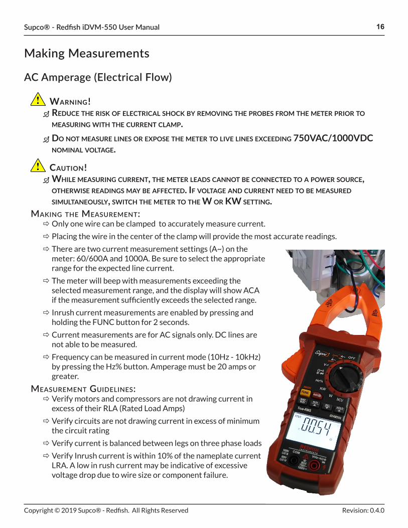
Making the MeasureMent: ÖOnly one wire can be clamped to accurately measure current.
Ö Placing the wire in the center of the clamp will provide the most accurate readings.
Ö There are two current measurement settings (A~) on the meter: 60/600A and 1000A. Be sure to select the appropriate range for the expected line current.
Ö The meter will beep with measurements exceeding the selected measurement range, and the display will show ACA if the measurement sufficiently exceeds the selected range.
Ö Inrush current measurements are enabled by pressing and holding the FUNC button for 2 seconds.
Ö Current measurements are for AC signals only. DC lines are not able to be measured.
Ö Frequency can be measured in current mode (10Hz - 10kHz) by pressing the Hz% button. Amperage must be 20 amps or greater.
MeasureMent guidelines: Ö Verify motors and compressors are not drawing current in excess of their RLA (Rated Load Amps)
Ö Verify circuits are not drawing current in excess of minimum the circuit rating
Ö Verify current is balanced between legs on three phase loads
Ö Verify Inrush current is within 10% of the nameplate current LRA. A low in rush current may be indicative of excessive voltage drop due to wire size or component failure.
caution! Ö While measuring current, the meter leads cannot be connected to a poWer source, otherWise readings may be affected. if voltage and current need to be measured simultaneously, sWitch the meter to the W or kW setting.
Making Measurements

Supco® - Redfish iDVM-550 User Manual 17
Copyright © 2019 Supco® - Redfish. All Rights Reserved Revision: 0.4.0
AC/DC Voltage (Electrical Pressure)
warning! Ö Do not measure lines or expose the meter to live lines exceeDing 750vac/1000vDc nominal voltage.
Ö if possible, measure high voltage circuits with a single hanD to avoiD situations where current can enter the boDy.
Ö perform the following steps to verify a circuit is DeenergizeD
1. Use NCV probe to detect for voltage (100 volts or higher)2. Measure from phase to phase of L1-N3. Measure from phase to ground
making the measurement: Ö Ensure the proper voltage type (AC or DC) is selected by pressing the FUNC key prior to making a measurement.
Ö The meter will beep with measurements exceeding the selected measurement range, and the display will show OL if the measurement sufficiently exceeds the selected range.
Ö Frequency can be measured in voltage mode (10Hz - 10kHz) by pressing the Hz% button.
caution! Ö when measuring Dc voltage, ensure that the leaDs are inserteD correctly (reD in the vhz port anD black in the com port). if not, the reaDings will reaD negative.
Ö if the measurement is questionable, measure a known source (i.e. householD receptacle) to verify that the meter is operational.
DC Voltage Measurement

Supco® - Redfish iDVM-550 User Manual 18
Copyright © 2019 Supco® - Redfish. All Rights Reserved Revision: 0.4.0
measurement guidelines:
Ö Before energizing equipment, verify the source voltage is equal to the that listed on the appliance or motor name plate to prevent equipment damage.
ÖWhile under normal operating conditions, verify that the voltage drop is less than 5% from the measured source voltage (per NEC guidelines).
Ö Do not measure from the source to the source ground unless the source return and the source ground have been verified to have the same potential.
ÖWhen troubleshooting potentially live equipment, always measure the load to verify if voltage is present.
ÖMeasure voltage across closed contactor switches on single and 3 phase circuits (L1-T1, L2-T2, L3-T3) to determine switch physical condition. Experience has shown that voltage drops in excess of .1 volt on 208/230 and .5 volt on 460/480 will generate significant amounts of heat. Clean switch or contacts and replace as needed.
ÖMeasure voltage drops across electrical disconnects to determine the condition of the disconnect. Experience has shown that voltage drops in excess of .1 volt on 208/230 and .5 volt on 460/480 will generate significant amounts of heat which can cause fuses to fail or the disconnect to catch fire. Look for an tighten loose connections when needed replace the disconnect.
ÖWhen measuring switches, an open switch will read the nominal voltage across it (i.e. 24V, 120V, 240V), and a closed switch will read 0 V.
ÖWhen checking 3-Phase circuits measure from phase to phase to determine that the voltage between phases does not have unacceptable levels of imbalance. Imbalance of more than 2-2.5% can cause significant current imbalance and motor overheating heating or failure.
AC/DC Voltage (Electrical Pressure)
AC Voltage Measurement

Supco® - Redfish iDVM-550 User Manual 19
Copyright © 2019 Supco® - Redfish. All Rights Reserved Revision: 0.4.0
measurement guidelines: Ö Used to verify electrical paths through switches on deenergized circuits
Ö Verify there are no unintended electrical paths on deenergized circuits. (Paths to ground)
Ö Verify fuses have no resistance. 0 ohms indicates a good fuse, OL or any measurable resistance indicates a bad fuse.
Ö Test each terminal of the compressor to clean copper pipe to determine if the compressor has a short to ground. High resistance readings Meg-Ohms may indicate moisture in the refrigerant. A good (dry) compressor should show OL.
Ö Test between compressor terminals to determine if there is an open winding or an open internal overload. A normal compressor will have measurable resistance from R-S, R-C and S-C. A compressor with an open internal overload will have measurable resistance from R-S but no resistance from R-C or S-C. Let the compressor cool for up to 24 hours to allow for reset.
Ö A compressor with an open winding will indicate resistance from C-S or R-S, but not from R-S
ÖOn three phase compressors and motors the resistance between terminals T1-T2, T2-T3, and T1-T3 should all be equal. Unequal resistances may cause overheating.
Resistance (Opposition to Current Flow)
Warning! Ö If measured In cIrcuIt, power should be removed and all capacItors dIscharged In the cIrcuIt prIor to takIng any resIstance measurements.
making the measurement: ÖWhen selecting the resistance/continuity/capacitance/diode mode on the meter, it will default to an autoscaling resistance mode.
ÖOpen circuits will be indicated with OL on the display.
Ö High resistance measurements (1MΩ or greater) may require time to stabilize.
Ö Low resistance measurements (5Ω or less) will vary significantly depending on the meter leads and quality of electrical contact to the circuit/device being measured.
Ö Touching the circuit being measured or the tips of the meter leads will affect resistance measurements.
Supco® - Redfish iDVM-550 User Manual 20
Copyright © 2019 Supco® - Redfish. All Rights Reserved Revision: 0.4.0
Diode Forward Drop
warning! Ö if measureD in circuit, power shoulD be removeD anD all capacitors DischargeD in the circuit prior to taking any DioDe measurements.
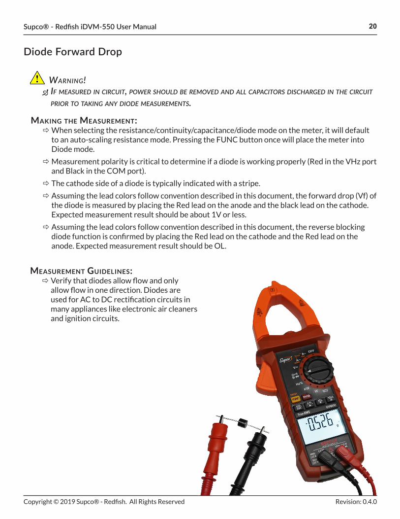
making the measurement: ÖWhen selecting the resistance/continuity/capacitance/diode mode on the meter, it will default to an auto-scaling resistance mode. Pressing the FUNC button once will place the meter into Diode mode.
ÖMeasurement polarity is critical to determine if a diode is working properly (Red in the VHz port and Black in the COM port).
Ö The cathode side of a diode is typically indicated with a stripe.
Ö Assuming the lead colors follow convention described in this document, the forward drop (Vf) of the diode is measured by placing the Red lead on the anode and the black lead on the cathode. Expected measurement result should be about 1V or less.
Ö Assuming the lead colors follow convention described in this document, the reverse blocking diode function is confirmed by placing the Red lead on the cathode and the Red lead on the anode. Expected measurement result should be OL.
measurement guidelines: Ö Verify that diodes allow flow and only allow flow in one direction. Diodes are used for AC to DC rectification circuits in many appliances like electronic air cleaners and ignition circuits.

Supco® - Redfish iDVM-550 User Manual 21
Copyright © 2019 Supco® - Redfish. All Rights Reserved Revision: 0.4.0
Continuity
warning! Ö if measureD in circuit, power shoulD be removeD anD all capacitors DischargeD in the circuit prior to taking any continuity measurements.
making the measurement: Ö If the measured resistance is 50Ω or less, the meter will beep to indicate that continuity is present.
Ö Resistance measurements are shown on the display.
Ö If an open circuit or resistance greater than 600Ω is detected, then the display will show OL.
Ö If an intermittent beep occurs, a poor electrical connection to the circuit under test is possibly at fault.
measurement guidelines: Ö Typically used for quick testing of open and closed control circuits when an audible tone is desired because viewing the display is not convenient.
Ö Tone out wires to find an open circuit
Ö Tone out wires to find a short circuit
Ö Can be used to quickly determine if a fuse is blown

Supco® - Redfish iDVM-550 User Manual 22
Copyright © 2019 Supco® - Redfish. All Rights Reserved Revision: 0.4.0
Capacitance
warning! Ö Discharge the capacitor prior to measuring the capacitance value. Ö never Discharge a capacitor using metallic objects that Directly short the capacitor terminals (i.e. screw Driver or jumper wire). it is recommenDeD to use a supco capDis pen for thie purpose.
making the measurement: Ö Capacitors should be removed from the circuit prior to measuring.
Ö Allow higher valued capacitors to stabilize prior to recording any measurements.
Ö Low value capacitors (10nF or less) may be affected by internal meter, probe, or body capacitance.
measurement guidelines: Ö Verify that the measured capacitance is within the allowable limits of the rated capacitance. Typical capacitors are measured in µF or microfarads, sometimes also abbreviated MFD, or MF.

Supco® - Redfish iDVM-550 User Manual 23
Copyright © 2019 Supco® - Redfish. All Rights Reserved Revision: 0.4.0
Frequency
warning! Ö Do not measure lines or expose the meter to live lines exceeDing 750vac/1000vDc nominal voltage.
making the measurement: Ö The meter will display frequencies ranging between 10Hz and 10MHz.
Ö Frequencies less than 10Hz are outside of the meter's capability, and the display will show 00.0 as the measured frequency.
Ö Frequencies greater than 10MHz may be measured and shown on the display, but accuracy above 10MHz is not guaranteed.
measurement guidelines: Ö Verify that the actual frequency supplied to the load is equal to the measured frequency
Ö Frequency output on VFD often cannot me measured because the drive outputs a PWM signal and requires a meter with a selectable low pass filter to make these readings. The Supco Redfish meter is not intended for this application.
Ö The iDVM 550 will accurately measure frequency on sinusoidal and square wave forms with or without harmonic distortion.

Supco® - Redfish iDVM-550 User Manual 24
Copyright © 2019 Supco® - Redfish. All Rights Reserved Revision: 0.4.0
Power, Phase, and Power Factor (PF)
key calculations:
1. Watts = Volts x Amps x PF
2. Coefficient of Performance (COP)
Ö COP = Watts output/Watts input
Ö Increase of COP = Increase of efficiency
Ö Decrease of COP = Decrease of efficiency
3. Energy Efficiency Ratio (EER)
Ö EER = BTUH/Watts
Ö Increase of EER = Increase of efficiency
Ö Decrease of EER = Decrease of efficiency
4. Fan Watt Draw (FWD)
Ö High FWD (.58 W/CFM) indicates inefficiency of the air delivery system
the poWer triangle:Commonly referred to as the power triangle, the figure below is used to calculate the real (active), reactive, and apparent power for a given circuit. In the simplest terms, a purely resistive circuit would have no VAr component, making the power factor angle equal to zero. This means that all the energy supplied to a load would be used by the load to do work, excluding any line or converter loses. In this scenario, the power factor (PF) would be one or unity, which is also the same as saying that the Apparent Power (VA) = Active Power (W).
However, as inductors are added to a circuit, the reactive power starts to increase. This causes the apparent power to increase, and as the apparent power increases, the current drawn by the load increases as well. Higher currents equate to more heat, lower efficiencies, larger wires, etc...
With an inductive load, the power factor, by definition, will be less than one. However, the addition of a capacitor in parallel with the load helps to counteract the inductor's reactive power; therefore, raising the PF closer to unity. This is commonly done with run capacitors on motors for this very reason.
Supco® - Redfish iDVM-550 User Manual 25
Copyright © 2019 Supco® - Redfish. All Rights Reserved Revision: 0.4.0
Power, Phase, and Power Factor (PF)
warning! Ö Do not measure lines or expose the meter to live lines exceeDing 750vac/1000vDc nominal voltage.
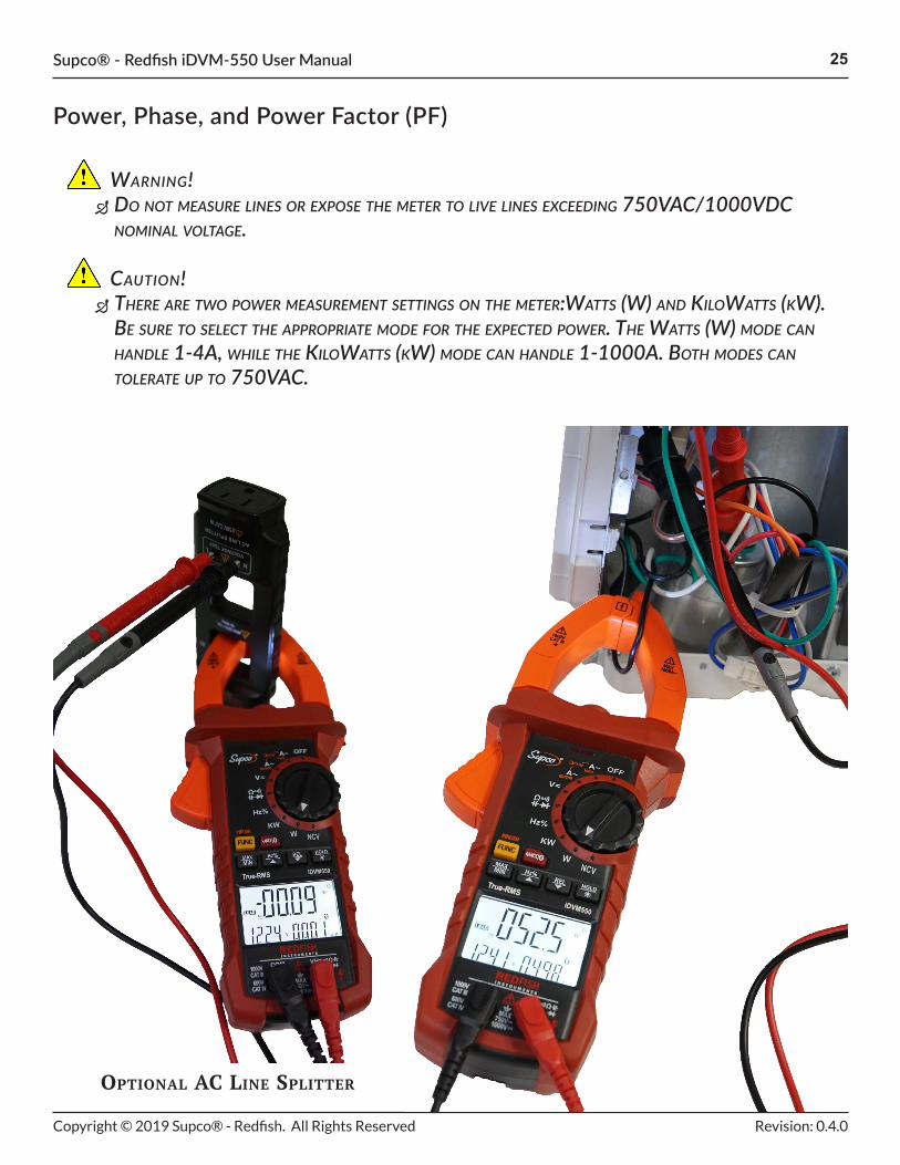
caution! Ö there are two power measurement settings on the meter:watts (w) anD kilowatts (kw). be sure to select the appropriate moDe for the expecteD power. the watts (w) moDe can hanDle 1-4a, while the kilowatts (kw) moDe can hanDle 1-1000a. both moDes can tolerate up to 750vac.
OptiOnal aC line Splitter
Supco® - Redfish iDVM-550 User Manual 26
Copyright © 2019 Supco® - Redfish. All Rights Reserved Revision: 0.4.0
Power, Phase, and Power Factor (PF)
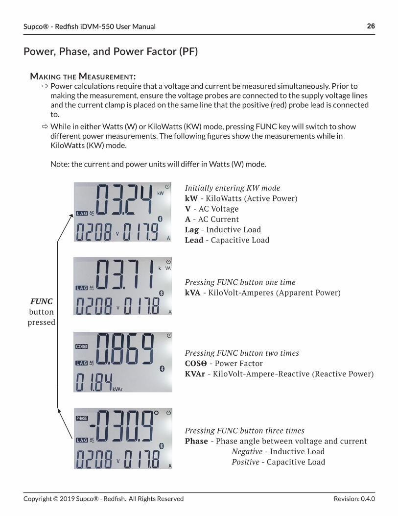
making the measurement: Ö Power calculations require that a voltage and current be measured simultaneously. Prior to making the measurement, ensure the voltage probes are connected to the supply voltage lines and the current clamp is placed on the same line that the positive (red) probe lead is connected to.
ÖWhile in either Watts (W) or KiloWatts (KW) mode, pressing FUNC key will switch to show different power measurements. The following figures show the measurements while in KiloWatts (KW) mode. Note: the current and power units will differ in Watts (W) mode.
Initially entering KW modekW - KiloWatts (Active Power)V - AC VoltageA - AC CurrentLag - Inductive LoadLead - Capacitive Load
Pressing FUNC button one timekVA - KiloVolt-Amperes (Apparent Power)
Pressing FUNC button two timesCOSѲ - Power FactorKVAr - KiloVolt-Ampere-Reactive (Reactive Power)
Pressing FUNC button three timesPhase - Phase angle between voltage and current Negative - Inductive Load Positive - Capacitive Load
FUNC button pressed

Supco® - Redfish iDVM-550 User Manual 27
Copyright © 2019 Supco® - Redfish. All Rights Reserved Revision: 0.4.0
Total Harmonic Distortion (THD)
This section describes Total Harmonic Distortion (THD), which is an extension of the previous section "Power, Phase, and Power Factor (PF)". The same safety guidelines and measurement techniques apply for making THD measurements.
thd summary
Typically, sinusoidal frequencies (50Hz or 60Hz) are used to power homes and buildings around the world. For purely resistive loads, the incoming line is not filled with unwanted distortion that can come from harmonic content. Harmonic content, multiples of the main frequency, can cause electrical issues to other devices on that line, or even worse cause issues with the electrical supplier. THD describes the total distortion or deviation from typical sine wave. As more and more harmonics appear, the distortion increases. The higher the THD percentage, the more likely that some corrective action is required.
As mentioned earlier in this document, inductive loads use reactive power, but that also means that they can cause harmonic distortion. Using the features on the iDVM 550 meter allows a technician to quickly diagnose potential issues with equipment and determine the overall quality of power being used.
making the measurement: ÖWhile in either Watts (W) or KiloWatts (kW) mode, pressing and holding the FUNC key for 2 seconds places the meter in THD mode. In this mode, the user must perform the following steps:
1. Attach meter leads and measure voltage of the voltage source2. Once the voltage source is measured, baseline frequency and peak voltage readings are recorded3. Turn on all loads to be measured, if not already on4. Press the FUNC key again (short press) and enter the harmonic viewing screen5. Use the Hz% (UP) and REL (DOWN) keys to toggle between harmonics

Supco® - Redfish iDVM-550 User Manual 28
Copyright © 2019 Supco® - Redfish. All Rights Reserved Revision: 0.4.0
Non-Contact Voltage (NCV)
warning! Ö reDuce the risk of electrical shock by removing the probes from the meter prior to testing with the ncv feature.
Ö Do not measure lines or expose the meter to live lines exceeDing 750vac/1000vDc nominal voltage.
Ö the ncv feature shoulD never be the sole source to Determine whether or not voltage is present. always verify presence, or lack thereof, of voltage by measuring with the voltage setting.
making the measurement: Ö The meter will beep and flash its purple NCV light (above the mode selector dial) as the meter head (top of the current clamp) approaches voltages of 100 VAC RMS or greater.
Ö The beep and flash will occur faster as the voltage source gets closer to the meter.
ÖOutside interference from noise, motors, etc... may cause the NCV to trigger.

Supco® - Redfish iDVM-550 User Manual 29
Copyright © 2019 Supco® - Redfish. All Rights Reserved Revision: 0.4.0
Mobile App
BTLE capability is only accessible using the Supco® TechLink™ or MeasureQuick mobile app. The App is available on the Google® Play Store for Android devices with BLE 4.0 or later and on the Apple® Store for iOS® devices with BLE 4.0 or later.
The App is free to download and provides the ability to log data, view measurement trends, generate reports, view troubleshooting tips, and monitor meter health (i.e. battery life).
Visit https://www.supcotechlink.com for more information and to download.
FREE DIAGNOSTIC APP