Embed Size (px)
Citation preview
EN 1~8
中 9~16
User Manual
IntroductionBasic Product InformationPackage List
PNP Install InsturctionsInstall Main WingInstall Horizontal StabilizerInstall Vertical StabilizerInstall PushrodPushrod instructionsBattery Size
122
334455
Center of GravityControl Direction TestDual Rates
Accessories DescriptionMotor SpecificationsMotor OverviewAccessories IntroductionServos IntroductionsInstall nose landing gearlnstall rear landing gear
1Item No.:FJ109
F-105 Thunderchief
Catalog
566
77
888
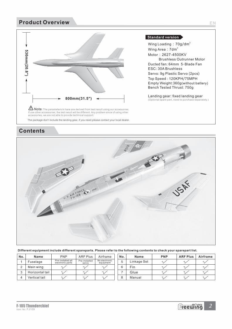
Contents
PNP ARF Plus Airframe
1
2
3
4
2Item No.:FJ109F-105 Thunderchief
Product Overview
800mm(31.5")
53
0m
m(2
0.8
")
2Wing Loading:70g/dm
2Wing�Area:7dm
Motor:2627-4500KV Brushless Outrunner Motor
Ducted fan: 64mm 5-Blade Fan
ESC: 30A Brushless
Servo: 9g Plastic Servo (2pcs)
Top Speed : 120KPH/75MPH
Empty Weight:360g(without battery)
Bench Tested Thrust: 750g
Landing gear: fixed landing gear(Optional spare part, need to purchase separately.)
Standard version
,The package don t include the landing gear, if you need,please contact your local dealer.
No. Name
5
6
7
8
PNP ARF Plus AirframeNo. Name
Glue
Fin

3Item No.:FJ109
F-105 Thunderchief
Step 1
Step 2
Carbon tube (Ø4x200mm)
As shown in this photo:
1.Insert the carbon tube into the fuselage and keep it in the center.
2.Apply the glue on the main wing install position of fuselage (Indicated position as the photo shown), then install the main wing on the fuselage and wait for it solidify.
Fuselage
Main wing
1.Use glue to attach the horizontal tail on the fuselage as the below photo shown.
PNP lnstallation Instructions
Install Main Wing
Install Horizontal Stabilizer
4Item No.:FJ109F-105 Thunderchief
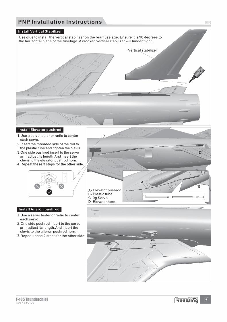
Use glue to install the vertical stabilizer on the rear fuselage. Ensure it is 90 degrees tothe horizontal plane of the fuselage. A crooked vertical stabilizer will hinder flight.
A
B
C
D
A-B-C-D-
Elevator pushrodPlastic tube9g ServoElevator horn
A
BC
Vertical stabilizer
PNP lnstallation Instructions
Install Vertical Stabilizer
1.Use a servo tester or radio to center each servo.
2.Insert the threaded side of the rod to the plastic tube and tighten the clevis.
3.One side pushrod insert to the servo arm,adjust its length.And insert the clevis to the elevator pushrod horn.4.Repeat these 3 steps for the other side.
1 Use a servo tester or radio to center . each servo.
2.One side pushrod insert to the servo arm,adjust its length.And insert the clevis to the aileron pushrod horn.
3.Repeat these 2 steps for the other side.
Install Elevator pushrod
Install Aileron pushrod
5Item No.:FJ109
F-105 Thunderchief
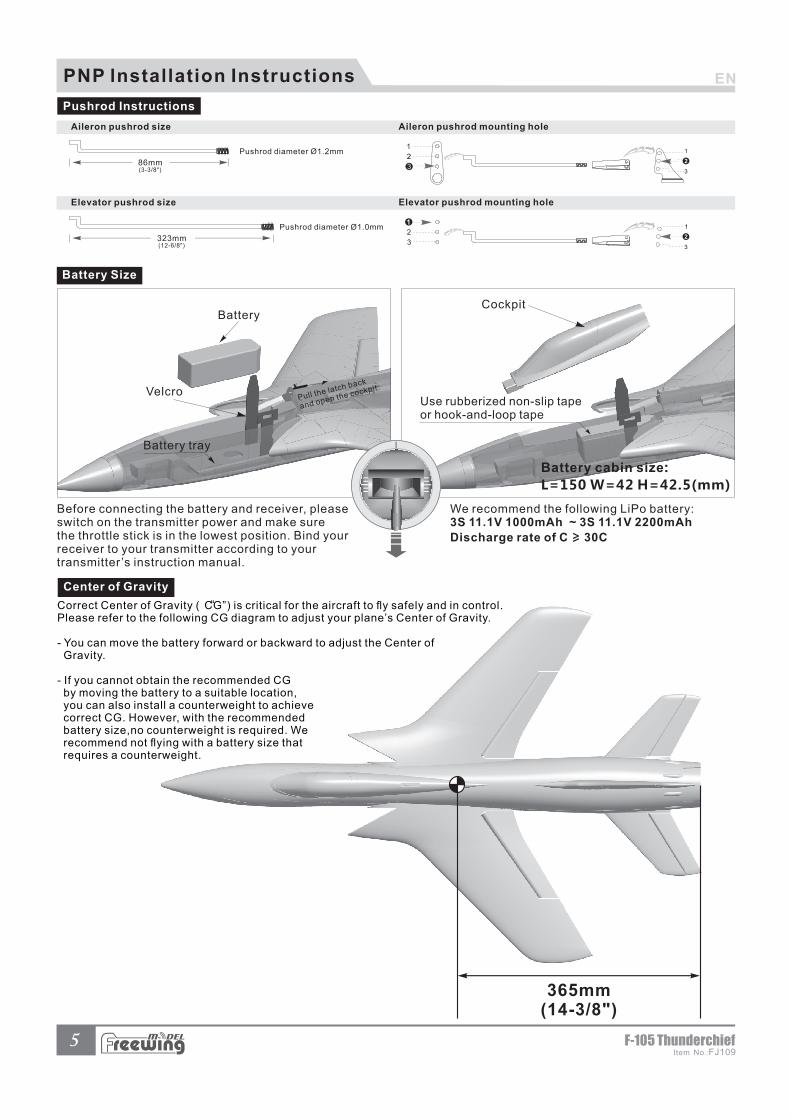
323mm(12-6/8")
Pushrod diameter Ø1.0mm 1
2
3
2
3
1
Pushrod diameter Ø1.2mm
86mm(3-3/8")
1
3
1
22
3
365mm(14-3/8")
PNP lnstallation Instructions
Pushrod Instructions
Elevator pushrod size Elevator pushrod mounting hole
Aileron pushrod mounting holeAileron pushrod size
Battery cabin size:
L=150 W=42 H=42.5(mm)
CockpitBattery
Velcro
Battery tray
Use rubberized non-slip tape or hook-and-loop tape
Pull the latch back
and open the cockpit.
Battery Size
We recommend the following LiPo battery:3S 11.1V 1000mAh ~ 3S 11.1V 2200mAh
> Discharge rate of C 30C
Before connecting the battery and receiver, pleaseswitch on the transmitter power and make surethe throttle stick is in the lowest position. Bind your receiver to your transmitter according to your transmitter ’s instruction manual.
Center of Gravity
Correct Center of Gravity ( CG”) is critical for the aircraft to fly safely and in control. ”Please refer to the following CG diagram to adjust your plane’s Center of Gravity.
- You can move the battery forward or backward to adjust the Center of Gravity.
- If you cannot obtain the recommended CG by moving the battery to a suitable location, you can also install a counterweight to achieve correct CG. However, with the recommended battery size,no counterweight is required. We recommend not flying with a battery size that requires a counterweight.
”
H1
H2
H1
H2
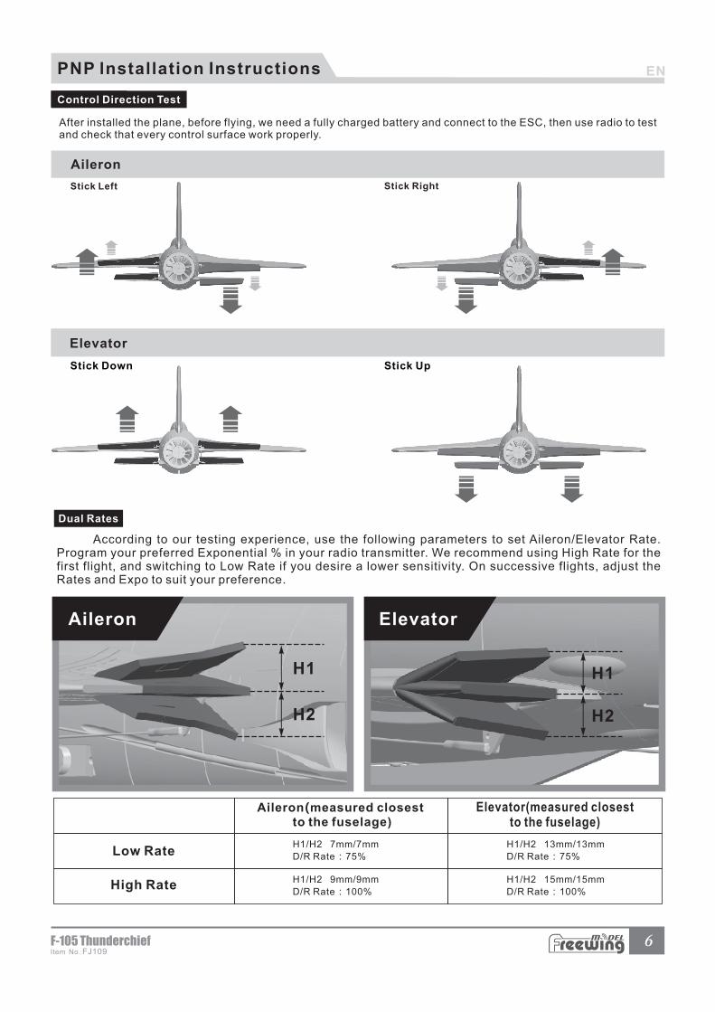
H1/H2 7mm/7mm
D/R Rate:75%
H1/H2 9mm/9mm
D/R Rate:100%
H1/H2 13mm/13mm
D/R Rate:75%
H1/H2 15mm/15mm
D/R Rate:100%
升降舵
舵 面 测 试
6Item No.:FJ109F-105 Thunderchief
PNP lnstallation Instructions
Control Direction Test
Stick Down Stick Up
Aileron Elevator
Low Rate
High Rate
Dual Rates
According to our testing experience, use the following parameters to set Aileron/Elevator Rate. Program your preferred Exponential % in your radio transmitter. We recommend using High Rate for the first flight, and switching to Low Rate if you desire a lower sensitivity. On successive flights, adjust the Rates and Expo to suit your preference.
Aileron(measured closest to the fuselage)
Elevator(measured closest to the fuselage)
AB
CD
E
F
G
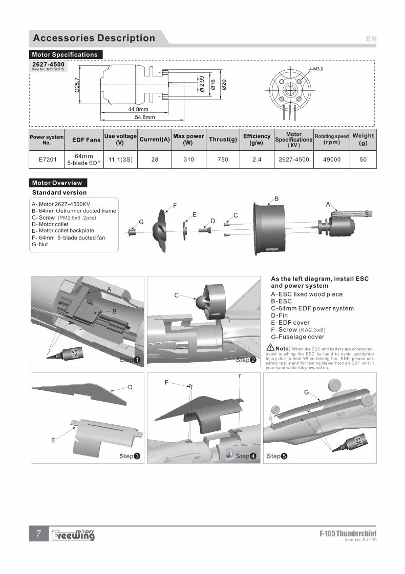
As the left diagram, install ESC and power system
A-B-C-D-E-F-G-
ESC fixed wood pieceESC64mm EDF power systemFinEDF coverScrew (KA2.3x8)
Fuselage cover
2627-4500Item No.:MO026272
7Item No.:FJ109
F-105 Thunderchief
CA
B
E
DF
G
Step 1 Step 2
Step 3 Step 4 Step 5
2627-450011.1(3S) 2864mm
5-blade EDF750 49000 50E7201 310 2.4
Weight
(g)Power system
No. Thrust(g) Current(A)
Use voltage(V)
Max power(W)
Efficiency(g/w)EDF Fans
MotorSpecifications
(KV)
Rotating speed
(rpm)
Motor Specifications
A-B-C-D-E-F-G-
Motor 2627-4500KV64mm Outrunner ducted frame
Screw (PM2.5x6 2pcs)
Motor colletMotor collet backplate
64mm 5-blade ducted fanNut
Motor Overview
Standard version
Note: When the ESC and battery are connected, avoid touching the ESC by hand to avoid accidental injury due to heat When testing the EDF, please use safety test stand for testing.Never hold an EDF unit in your hand while it is powered on.
Accessories Description
1
2
8Item No.:FJ109F-105 Thunderchief
Accessories Introduction
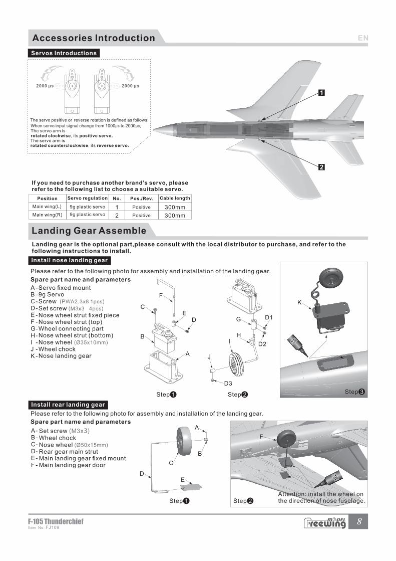
Servos Introductions
Main wing(L)
Main wing(R)
1
2
Positive
Positive
300mm
300mm
9g plastic servo
9g plastic servo
Servo regulation Pos./Rev. Cable lengthPosition No.
If you need to purchase another brand’s servo, pleaserefer to the following list to choose a suitable servo.
Step 1
A
B
CE
F
D
Step 2
G
H
J
D1
D2
D3
I
Step 3
K
Spare part name and parameters
A -B -C-D-E -F -G-H-I -J -K -
Servo fixed mount9g ServoScrew (PWA2.3x8 1pcs)
Set screw (M3x3 4pcs)
Nose wheel strut fixed pieceNose wheel strut (top)Wheel connecting partNose wheel strut (bottom)Nose wheel (Ø35x10mm)
Wheel chockNose landing gear
Install nose landing gear
Please refer to the following photo for assembly and installation of the landing gear.
A-B-C-D-E-F -
Set screw (M3x3)Wheel chockNose wheel (Ø50x15mm)
Rear gear main strutMain landing gear fixed mountMain landing gear door
Step 1 Step 2
A
B
C
DE
F
Attention: install the wheel on the direction of nose fuselage.
Please refer to the following photo for assembly and installation of the landing gear.
Install rear landing gear
Spare part name and parameters
Landing Gear Assemble
Landing gear is the optional part,please consult with the local distributor to purchase, and refer to the following instructions to install.

Add.:FeiYi Building,face to Labor Bureau, Fumin Middle Road, Dalang Town, Dongguan City,Guangdong Province, China
HK Freewing Model International Limited
东莞市飞翼电子科技有限公司香港飞翼模型国际有限公司地址: 广东省东莞市大朗镇富民中路402-408号飞翼楼四楼Web: http://www.sz-freewing.com
Email:[email protected]
Tel: 86-769-82669669 Fax:86-769-82033233
Web: http://www.sz-freewing.com
Email:[email protected]
Tel: 86-769-82669669 Fax:86-769-82033233
Dongguan Freewing Electronic Technology Ltd
R


![[aviation] - [Squadron-Signal] - [Walk Around n°23] - F-105 Thunderchief](https://img.pdfslide.net/doc/110x75/545444b2b1af9f04298b492b/aviation-squadron-signal-walk-around-n23-f-105-thunderchief.jpg)