Embed Size (px)
Citation preview
User Manual STAR T3 Series UPS
6/10 kVA www.allis.com.tw
User manual 6/10 kVA Rev.4
ALLIS ELECTRIC -i- August 2006
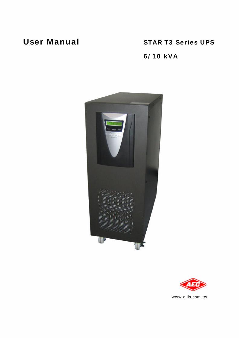
Contents
1. Presentation .......................................................................................................1
1.1 General Description ........................................................................................... 1 1.2 System Configuration......................................................................................... 2 1.3 Front Panel ...................................................................................................... 3 ? ? LCD............................................................................................................ 3 ? ? LED............................................................................................................ 3
1.4 Rear Panel ....................................................................................................... 4 ? 6/10 kVA..................................................................................................... 4 ? Extended Battery Bank .................................................................................. 5
2. Installation.........................................................................................................6
2.1 Unpacking........................................................................................................ 6 2.2 Installation ...................................................................................................... 7 ? Standard ..................................................................................................... 7 ? External Battery ........................................................................................... 8 ? Parallel........................................................................................................ 9
2.3 Connection to communication............................................................................ 10 2.3.1 Standard ................................................................................................. 10
? RS-232 ............................................................................................ 10 2.3.2 Optional Interface Cards............................................................................. 11
? USB Card.......................................................................................... 11 ? DB9 Dry Contact Card......................................................................... 11 ? AS400 Card ...................................................................................... 12 ? SNMP/HTTP Agent .............................................................................. 12
3. Operation ......................................................................................................... 13
3.1 LCD and LED Display ....................................................................................... 13 ? LCD.......................................................................................................... 13 ? LED.......................................................................................................... 15
3.2 Starting up/ Shutting down the UPS ................................................................... 16 3.3 Operation Modes ............................................................................................. 17 3.4 Configuration Settings...................................................................................... 18 ? Output Voltage / Frequency.......................................................................... 18 ? Bypass Voltage........................................................................................... 19
4. Maintenance ..................................................................................................... 20
4.1 General Maintenance ....................................................................................... 20 ? Environment .............................................................................................. 20 ? Storing the UPS and Battery ......................................................................... 20 ? Replace the Battery..................................................................................... 20
4.2 Replacing the New Battery ................................................................................ 21 4.3 Testing the New Battery ................................................................................... 21 4.4 Recycling the Used Battery ............................................................................... 21 4.5 Maintenance Bypass ........................................................................................ 22 ? Switch to bypass......................................................................................... 22 ? Return from bypass to normal mode .............................................................. 22
5. Troubleshooting ................................................................................................ 23
? LCD.......................................................................................................... 23 ? LED.......................................................................................................... 25
6. Appendix .......................................................................................................... 28
6.1 Specifications ................................................................................................. 28 ? General Specification................................................................................... 28 ? Battery Run Time ........................................................................................ 29
6.2 Contact Information......................................................................................... 30
User manual 6/10 kVA Rev.4
ALLIS ELECTRIC -ii- August 2006
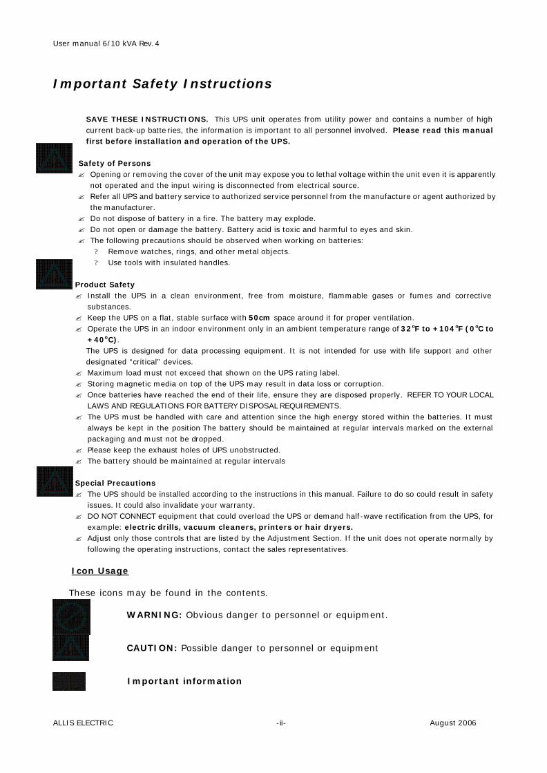
Important Safety Instructions
SAVE THESE INSTRUCTIONS. This UPS unit operates from utility power and contains a number of high current back-up batteries, the information is important to all personnel involved. Please read this manual first before installation and operation of the UPS.
Safety of Persons ? Opening or removing the cover of the unit may expose you to lethal voltage within the unit even it is apparently
not operated and the input wiring is disconnected from electrical source. ? Refer all UPS and battery service to authorized service personnel from the manufacture or agent authorized by
the manufacturer. ? Do not dispose of battery in a fire. The battery may explode. ? Do not open or damage the battery. Battery acid is toxic and harmful to eyes and skin. ? The following precautions should be observed when working on batteries:
? Remove watches, rings, and other metal objects. ? Use tools with insulated handles.
Product Safety ? Install the UPS in a clean environment, free from moisture, flammable gases or fumes and corrective
substances. ? Keep the UPS on a flat, stable surface with 50cm space around it for proper ventilation. ? Operate the UPS in an indoor environment only in an ambient temperature range of 32oF to +104oF (0oC to
+40oC). The UPS is designed for data processing equipment. It is not intended for use with life support and other designated “critical” devices.
? Maximum load must not exceed that shown on the UPS rating label. ? Storing magnetic media on top of the UPS may result in data loss or corruption. ? Once batteries have reached the end of their life, ensure they are disposed properly. REFER TO YOUR LOCAL
LAWS AND REGULATIONS FOR BATTERY DISPOSAL REQUIREMENTS. ? The UPS must be handled with care and attention since the high energy stored within the batteries. It must
always be kept in the position The battery should be maintained at regular intervals marked on the external packaging and must not be dropped.
? Please keep the exhaust holes of UPS unobstructed. ? The battery should be maintained at regular intervals
Special Precautions ? The UPS should be installed according to the instructions in this manual. Failure to do so could result in safety
issues. It could also invalidate your warranty. ? DO NOT CONNECT equipment that could overload the UPS or demand half-wave rectification from the UPS, for
example: electric drills, vacuum cleaners, printers or hair dryers. ? Adjust only those controls that are listed by the Adjustment Section. If the unit does not operate normally by
following the operating instructions, contact the sales representatives.
Icon Usage These icons may be found in the contents.
WARNING: Obvious danger to personnel or equipment. CAUTION: Possible danger to personnel or equipment Important information
User manual 6/10 kVA Rev.4
ALLIS ELECTRIC -iii- August 2006
Limited product warranty and policy ? Limited Product Warranty-
AEC warrants this equipment, when properly applied and operated within specified conditions, against faulty materials or workmanship for a period of 24 months after the date of purchase. For equipment located outside Taiwan, AEC only covers faulty parts. AEC products repaired or replaced pursuant to this warranty shall be warranted for the unexpired portion of the warranty applying to the original product. This warranty applies only to the original purchaser.
This warranty does not cover shipping costs, installation costs, maintenance and service items, calibration and adjustment. Repair or replacement of a defective part, or the crediting to the user of the value thereof, does not extend the original warranty period.
? Warranty policy-
The warranty shall be void if (a) the equipment is damaged by the customer, is improperly used, is subjected to an adverse operating environment, or is operated outside the limits of its electrical specifications; (b) the equipment is repaired or modified by anyone other than AEC or AEC-approved personnel; or (c) has been used in a manner contrary to the product’s operating manual or other written instructions. All claims under this warranty must be submitted in writing to AEC within 30 days of the occurrence or the claim will not be considered. This warranty does not include damage resulting from accident or misuse.
AEC reserves the right to determine whether the damage to the connected equipment is due to malfunction of the AEC product by requesting the equipment in question to be sent to AEC for examination. This policy is above and beyond, only to the extent needed, of that provided by any coverage of connected equipment provided by other sources, including, but not limited to, any manufacturer's warranty and/or any extended warranties.
EXCEPT AS PROVIDED ABOVE, AEC MAKES NO WARRANTIES, EXPRESS OR IMPLIED, INCLUDING WARRANTIES OF MERCHANTABILITY AND FITNESS FOR A PARTICULAR PURPOSE.
EXCEPT AS PROVIDED ABOVE, IN NO EVENT WILL AEC BE LIABLE FOR DIRECT, INDIRECT, SPECIAL, INCIDENTAL OR CONSEQUENTIAL DAMAGES ARISING OUT OF THE USE OF THIS PRODUCT, EVEN IF ADVISED OF THE POSSIBILITY OF SUCH DAMAGE. Specifically, AEC is not liable for any costs, such as lost profits or revenue, loss of equipment, loss of use of equipment, loss of software, loss of data, costs of substitutes, claims by third parties or otherwise. Coverage also does not apply to connected medical and industrial equipment.
To receive service under this warranty, you must be the original purchaser/user of the product in question. You must obtain a Returned Material Authorization (RMA) number from AEC. Products must be returned to AEC with transportation charges prepaid and must be accompanied by a brief description of the problem encountered and proof of date and place of purchase.
The policy of AEC is one of continuous improvement. Specifications are subject to change without notice.
User manual 6/10 kVA Rev.4
ALLIS ELECTRIC - Page 1 of Total 30 - August 2006
1. Presentation 1.1 General Description The continuity of electrical power is an essential requirement for critical load operations .The Uninterruptible Power System (UPS) is a compact and quiet solution for power protection of computer, server and office equipment. To choose the UPS as your equipment protector is a wise investment as it supplies reliable, pure and stable power at an affordable price. Feature & Benefits: ? True on-line double conversion ? PWM technologies w/ IGBTs ? Wide input voltage range ? DC Start ? Battery self-test ? Microprocessor based control ? User-friendly LCD or LED ? Communication ports: Standard RS232 and optional communication slot for either DB9,
USB, AS-400 or SNMP/HTTP card. ? Light weight unit ? Optional external battery slot for long runtime requirement ? DSP Technology ? Parallel redundancy capability Application: ? Computers ? Network Servers ? Workstations ? Wireless Communication ? Other Electronic Peripherals
User manual 6/10 kVA Rev.4
ALLIS ELECTRIC - Page 2 of Total 30 - August 2006
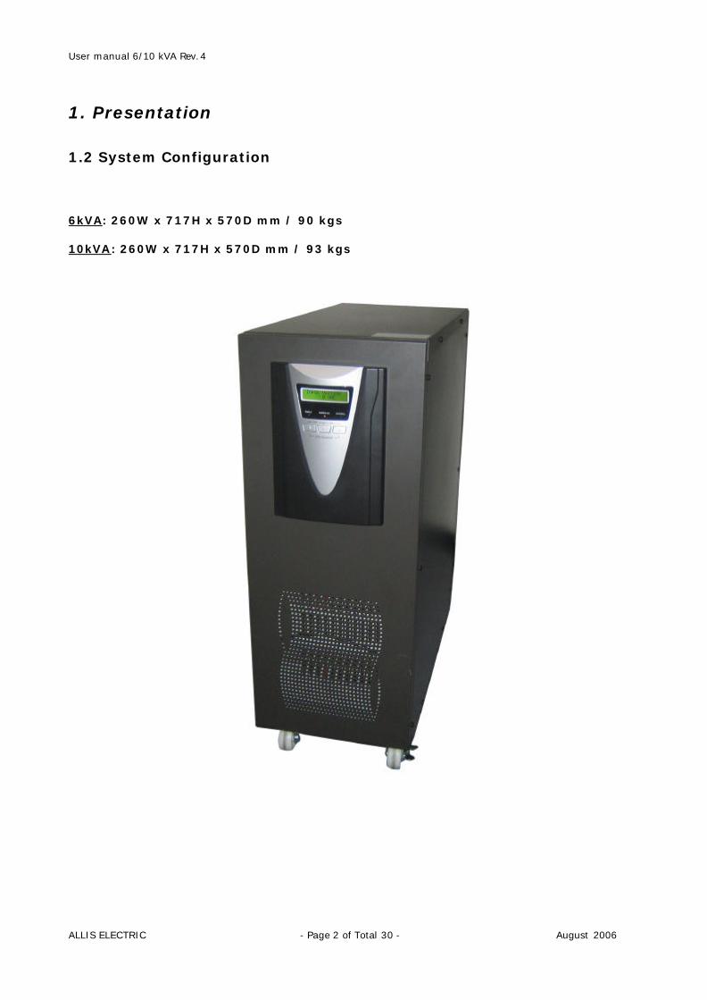
1. Presentation 1.2 System Configuration 6kVA: 260W x 717H x 570D mm / 90 kgs 10kVA: 260W x 717H x 570D mm / 93 kgs
User manual 6/10 kVA Rev.4
ALLIS ELECTRIC - Page 3 of Total 30 - August 2006
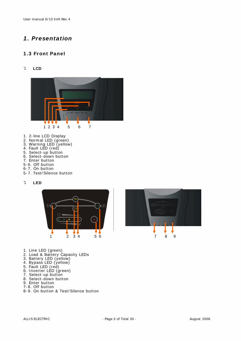
1. Presentation 1.3 Front Panel ? LCD 1 2 3 4 5 6 7 1. 2-line LCD Display 2. Normal LED (green) 3. Warning LED (yellow) 4. Fault LED (red) 5. Select-up button 6. Select-down button 7. Enter button 5-6. Off button 6-7. On button 5-7. Test/Silence button ? LED 1 2 3 4 5 6 7 8 9 1. Line LED (green) 2. Load & Battery Capacity LEDs 3. Battery LED (yellow) 4. Bypass LED (yellow) 5. Fault LED (red) 6. Inverter LED (green) 7. Select-up button 8. Select-down button 9. Enter button 7-8. Off button 8-9. On button & Test/Silence button
User manual 6/10 kVA Rev.4
ALLIS ELECTRIC - Page 4 of Total 30 - August 2006
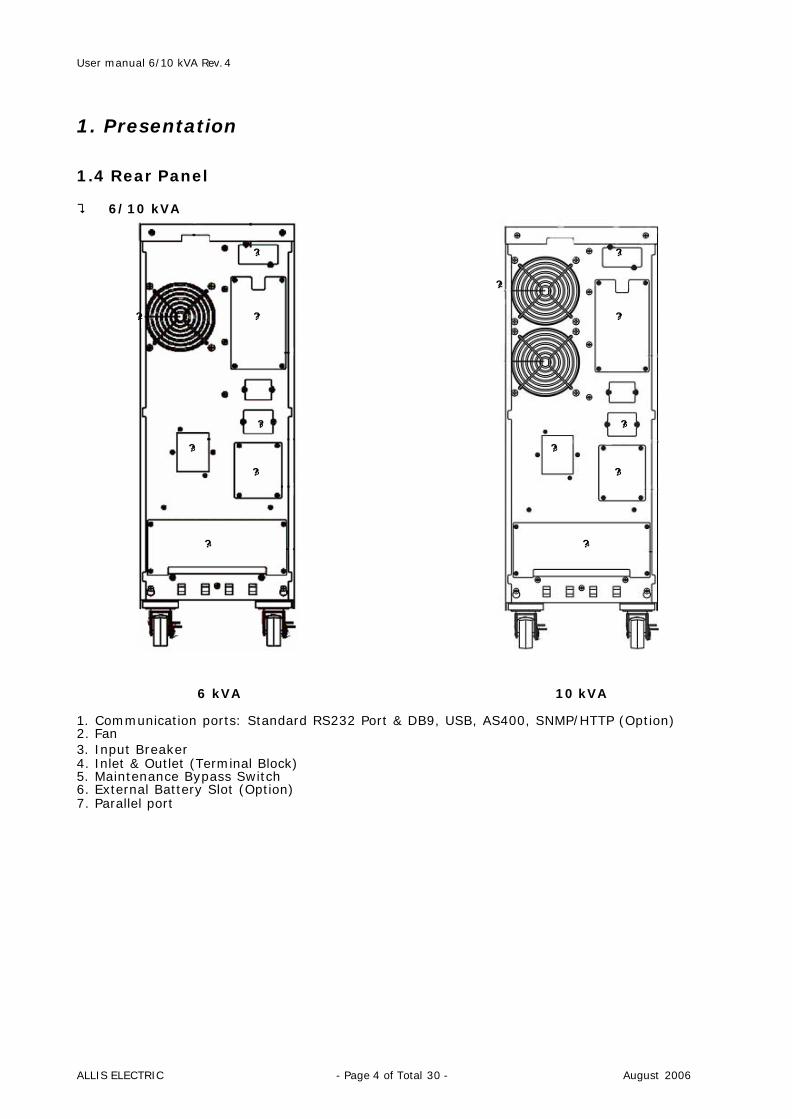
1. Presentation 1.4 Rear Panel ? 6/10 kVA
?1 ?1
?2
?2 ?7 ?7
?6 ?6 ?3 ?3
?5 ?5
?4 ?4
6 kVA 10 kVA 1. Communication ports: Standard RS232 Port & DB9, USB, AS400, SNMP/HTTP (Option) 2. Fan 3. Input Breaker 4. Inlet & Outlet (Terminal Block) 5. Maintenance Bypass Switch 6. External Battery Slot (Option) 7. Parallel port
User manual 6/10 kVA Rev.4
ALLIS ELECTRIC - Page 5 of Total 30 - August 2006
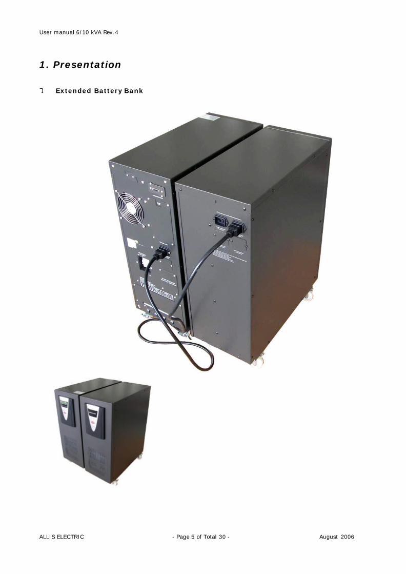
1. Presentation ? Extended Battery Bank
User manual 6/10 kVA Rev.4
ALLIS ELECTRIC - Page 6 of Total 30 - August 2006
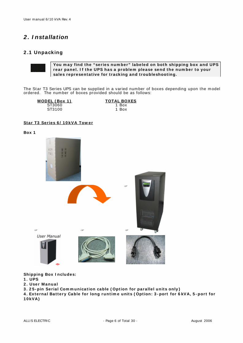
2. Installation 2.1 Unpacking The Star T3 Series UPS can be supplied in a varied number of boxes depending upon the model ordered. The number of boxes provided should be as follows: MODEL (Box 1) TOTAL BOXES ST3060 1 Box ST3100 1 Box Star T3 Series 6/10kVA Tower Box 1 ? ? ? ? Shipping Box Includes: 1. UPS 2. User Manual 3. 25-pin Serial Communication cable (Option for parallel units only) 4. External Battery Cable for long runtime units (Option: 3-port for 6kVA, 5-port for 10kVA)
You may find the “series number” labeled on both shipping box and UPS rear panel. If the UPS has a problem please send the number to your sales representative for tracking and troubleshooting.
User manual 6/10 kVA Rev.4
ALLIS ELECTRIC - Page 7 of Total 30 - August 2006
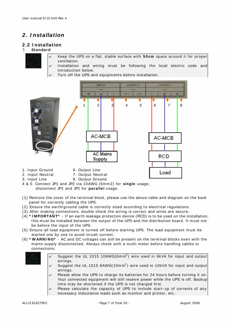
2. Installation 2.2 Installation ? Standard 1 2 3 4 5 6 7 8 1. Input Ground 6. Output Line 2. Input Neutral 7. Output Neutral 3. Input Line 8. Output Ground 4 & 5. Connect JP1 and JP2 via 10AWG (6mm2) for single usage,
disconnect JP1 and JP2 for parallel usage. (1) Remove the cover of the terminal block, please use the above table and diagram on the back
panel for correctly cabling the UPS. (2) Ensure the earth/ground cable is correctly sized according to electrical regulations. (3) After making connections, double check the wiring is correct and wires are secure. (4) *IMPORTANT* - If an earth leakage protection device (RCD) is to be used on the installation,
this must be installed between the output of the UPS and the distribution board. It must not be before the input of the UPS.
(5) Ensure all load equipment is turned off before starting UPS. The load equipment must be started one by one to avoid inrush current.
(6) *WARNING* - AC and DC voltages can still be present on the terminal blocks even with the mains supply disconnected. Always check with a multi-meter before handling cables or connections.
? Keep the UPS on a flat, stable surface with 50cm space around it for proper ventilation.
? Installation and wiring must be following the local electric code and introduction below.
? Turn off the UPS and equipments before installation.
? Suggest the UL 1015 10AWG(6mm2) wire used in 6kVA for input and output wirings.
? Suggest the UL 1015 8AWG(10mm2) wire used in 10kVA for input and output wirings.
? Please allow the UPS to charge its batteries for 24 hours before turning it on. Your connected equipment will still receive power while the UPS is off. Backup time may be shortened if the UPS is not charged first.
? Please calculate the capacity of UPS to include start-up of currents of any necessary inductance loads such as monitor and printer, etc.

User manual 6/10 kVA Rev.4
ALLIS ELECTRIC - Page 8 of Total 30 - August 2006
2. Installation ? External Battery
for battery bank
for loosing batteries (1) For the long runtime application, please make sure the battery voltage must be 240 VDC
nominal. (2) Connect the external battery with the proper external battery cable as shown pictures above. (3) After making connections, double check the wiring is correct and wires are secure.
User manual 6/10 kVA Rev.4
ALLIS ELECTRIC - Page 9 of Total 30 - August 2006
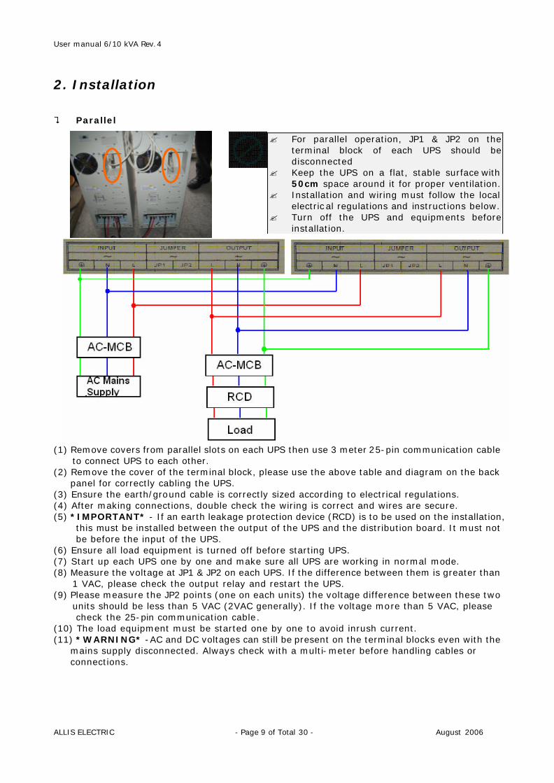
2. Installation ? Parallel
(1) Remove covers from parallel slots on each UPS then use 3 meter 25-pin communication cable
to connect UPS to each other. (2) Remove the cover of the terminal block, please use the above table and diagram on the back
panel for correctly cabling the UPS. (3) Ensure the earth/ground cable is correctly sized according to electrical regulations. (4) After making connections, double check the wiring is correct and wires are secure. (5) *IMPORTANT* - If an earth leakage protection device (RCD) is to be used on the installation,
this must be installed between the output of the UPS and the distribution board. It must not be before the input of the UPS.
(6) Ensure all load equipment is turned off before starting UPS. (7) Start up each UPS one by one and make sure all UPS are working in normal mode. (8) Measure the voltage at JP1 & JP2 on each UPS. If the difference between them is greater than
1 VAC, please check the output relay and restart the UPS. (9) Please measure the JP2 points (one on each units) the voltage difference between these two
units should be less than 5 VAC (2VAC generally). If the voltage more than 5 VAC, please check the 25-pin communication cable.
(10) The load equipment must be started one by one to avoid inrush current. (11) *WARNING* -AC and DC voltages can still be present on the terminal blocks even with the
mains supply disconnected. Always check with a multi-meter before handling cables or connections.
? For parallel operation, JP1 & JP2 on the terminal block of each UPS should be disconnected
? Keep the UPS on a flat, stable surface with 50cm space around it for proper ventilation.
? Installation and wiring must follow the local electrical regulations and instructions below.
? Turn off the UPS and equipments before installation.
User manual 6/10 kVA Rev.4
ALLIS ELECTRIC - Page 10 of Total 30 - August 2006
2. Installation 2.3 Connection to communication 2.3.1 Standard ? RS-232
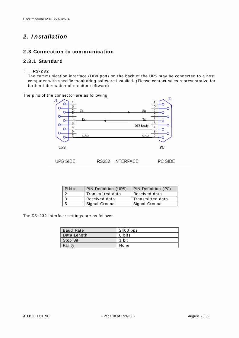
The communication interface (DB9 port) on the back of the UPS may be connected to a host computer with specific monitoring software installed. (Please contact sales representative for further information of monitor software)
The pins of the connector are as following:
The RS-232 interface settings are as follows:
PIN # PIN Definition (UPS) PIN Definition (PC) 2 Transmitted data Received data 3 Received data Transmitted data 5 Signal Ground Signal Ground
Baud Rate 2400 bps Data Length 8 bits Stop Bit 1 bit Parity None
User manual 6/10 kVA Rev.4
ALLIS ELECTRIC - Page 11 of Total 30 - August 2006
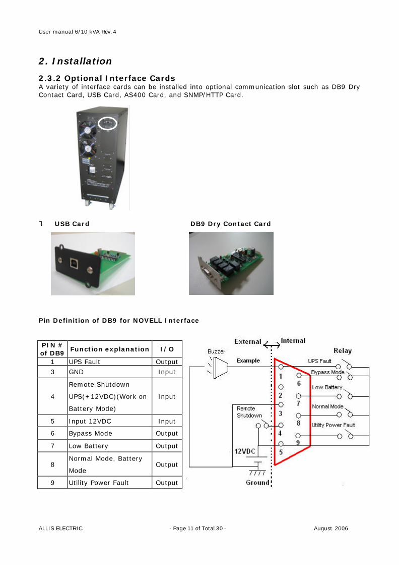
2. Installation 2.3.2 Optional Interface Cards A variety of interface cards can be installed into optional communication slot such as DB9 Dry Contact Card, USB Card, AS400 Card, and SNMP/HTTP Card. ? USB Card DB9 Dry Contact Card Pin Definition of DB9 for NOVELL Interface PIN # of DB9
Function explanation I/O
1 UPS Fault Output
3 GND Input
4
Remote Shutdown
UPS(+12VDC)(Work on
Battery Mode)
Input
5 Input 12VDC Input
6 Bypass Mode Output
7 Low Battery Output
8 Normal Mode, Battery
Mode Output
9 Utility Power Fault Output
User manual 6/10 kVA Rev.4
ALLIS ELECTRIC - Page 12 of Total 30 - August 2006
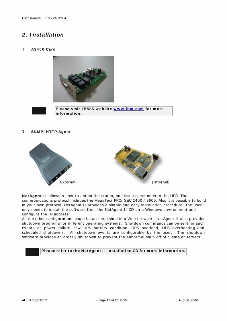
2. Installation ? AS400 Card ? SNMP/HTTP Agent (External) (Internal) NetAgent II allows a user to obtain the status, and issue commands to the UPS. The communications protocol includes the MegaTec/ PPC/ SEC 2400 / 9600. Also it is possible to build in your own protocol. NetAgent II provides a simple and easy installation procedure. The user only needs to install the software from the NetAgent II CD on a Windows environment and configure the IP address. All the other configurations could be accomplished in a Web browser. NetAgent II also provides shutdown programs for different operating systems. Shutdown commands can be sent for such events as power failure, low UPS battery condition, UPS overload, UPS overheating and scheduled shutdowns. All shutdown events are configurable by the user. The shutdown software provides an orderly shutdown to prevent the abnormal shut-off of clients or servers.
Please visit IBM’S website www.ibm.com for more information.
Please refer to the NetAgent II installation CD for more information.
User manual 6/10 kVA Rev.4
ALLIS ELECTRIC - Page 13 of Total 30 - August 2006
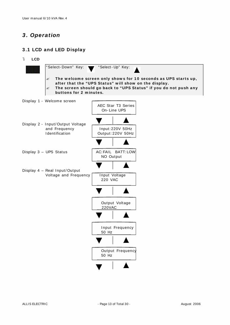
3. Operation 3.1 LCD and LED Display ? LCD Display 1 - Welcome screen AEC Star T3 Series On-Line UPS Display 2 - Input/Output Voltage
and Frequency Input:220V 50Hz Identification Output:220V 50Hz Display 3 – UPS Status AC:FAIL BATT:LOW NO Output Display 4 – Real Input/Output
Voltage and Frequency Input Voltage 220 VAC Output Voltage 220VAC Input Frequency 50 Hz Output Frequency 50 Hz
“Select-Down” Key: “Select-Up” Key:
? The welcome screen only shows for 10 seconds as UPS starts up, after that the “UPS Status” will show on the display.
? The screen should go back to “UPS Status” if you do not push any buttons for 2 minutes.
User manual 6/10 kVA Rev.4
ALLIS ELECTRIC - Page 14 of Total 30 - August 2006
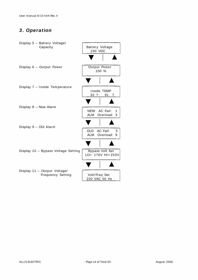
3. Operation Display 5 – Battery Voltage/ Capacity Battery Voltage 240 VDC Display 6 – Output Power Output Power 100 % Display 7 – Inside Temperature Inside TEMP 33 ? 91 ? Display 8 – New Alarm NEW AC Fail: 1 ALM Overload: 3 Display 9 – Old Alarm OLD AC Fail: 5 ALM Overload: 9 Display 10 – Bypass Voltage Setting Bypass Volt Set LO= 176V HI=253V Display 11 – Output Voltage/ Frequency Setting Volt/Freq Set 220 VAC 50 Hz
User manual 6/10 kVA Rev.4
ALLIS ELECTRIC - Page 15 of Total 30 - August 2006
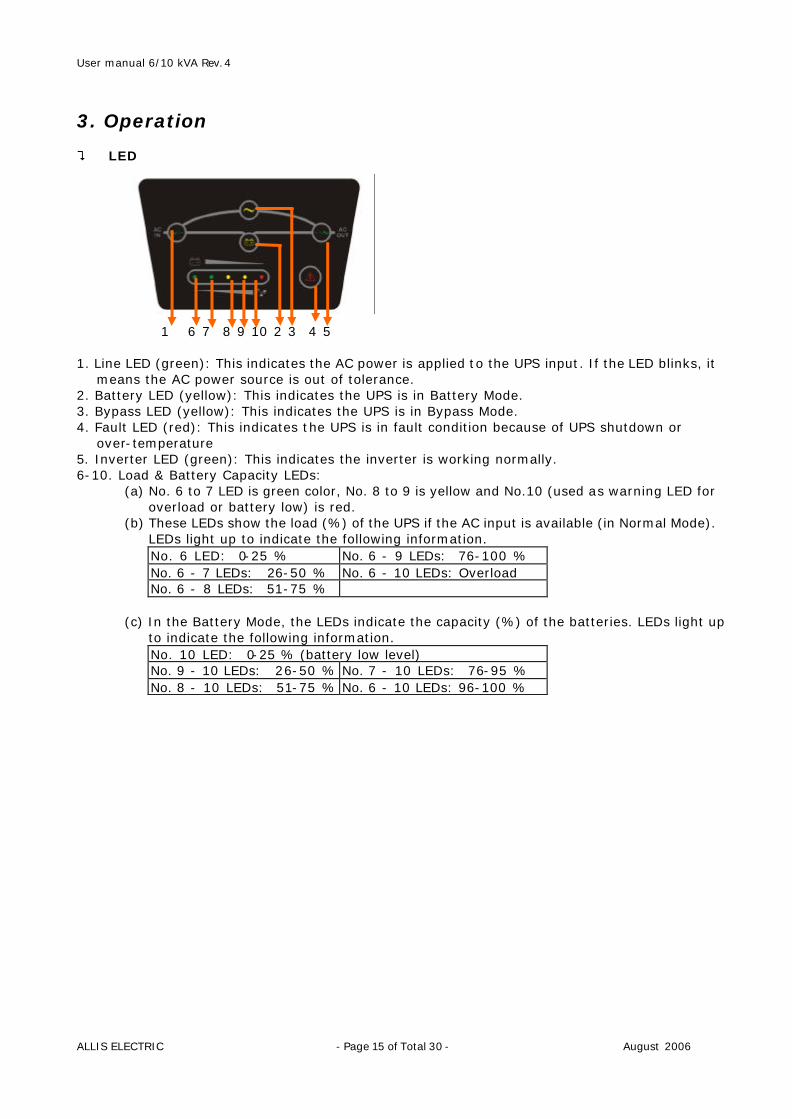
3. Operation ? LED 1 6 7 8 9 10 2 3 4 5 1. Line LED (green): This indicates the AC power is applied to the UPS input. If the LED blinks, it
means the AC power source is out of tolerance. 2. Battery LED (yellow): This indicates the UPS is in Battery Mode. 3. Bypass LED (yellow): This indicates the UPS is in Bypass Mode. 4. Fault LED (red): This indicates the UPS is in fault condition because of UPS shutdown or
over-temperature 5. Inverter LED (green): This indicates the inverter is working normally. 6-10. Load & Battery Capacity LEDs:
(a) No. 6 to 7 LED is green color, No. 8 to 9 is yellow and No.10 (used as warning LED for overload or battery low) is red.
(b) These LEDs show the load (%) of the UPS if the AC input is available (in Normal Mode). LEDs light up to indicate the following information. No. 6 LED: 0-25 % No. 6 - 9 LEDs: 76-100 % No. 6 - 7 LEDs: 26-50 % No. 6 - 10 LEDs: Overload No. 6 - 8 LEDs: 51-75 %
(c) In the Battery Mode, the LEDs indicate the capacity (%) of the batteries. LEDs light up
to indicate the following information. No. 10 LED: 0-25 % (battery low level) No. 9 - 10 LEDs: 26-50 % No. 7 - 10 LEDs: 76-95 % No. 8 - 10 LEDs: 51-75 % No. 6 - 10 LEDs: 96-100 %
User manual 6/10 kVA Rev.4
ALLIS ELECTRIC - Page 16 of Total 30 - August 2006
3. Operation 3.2 Starting up/ Shutting down the UPS ? Start ing up of the UPS
Step 1. Connect the UPS into an AC mains supply and the UPS will enter Bypass mo de. Step 2. Press the “Select-down” & “Enter” buttons simultaneously to switch on UPS. The UPS will begin its start-up process. After entering the Normal Mode, the UPS is
ready for operation. ? Shutting down the UPS
Press the “Select-up” & “Select –down” buttons simultaneously for a few seconds. The UPS will Turn off.
? Battery Start-up of the UPS
Step 1: Unplug the UPS from any AC mains supply. Step 2: Press the “Select-down” & “Enter” buttons simultaneously to switch on UPS. The UPS will begin its start-up process. After entering the Battery Mode, the UPS is ready for operation.
During shutdown, do not press any buttons. Pressing a button may cause the UPS to re-energize and deliver output power.
User manual 6/10 kVA Rev.4
ALLIS ELECTRIC - Page 17 of Total 30 - August 2006
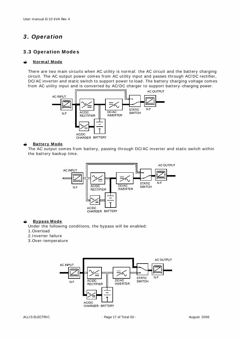
3. Operation 3.3 Operation Modes ? Normal Mode
There are two main circuits when AC utility is normal: the AC circuit and the battery charging circuit. The AC output power comes from AC utility input and passes through AC/DC rectifier, DC/AC inverter and static switch to support power to load. The battery charging voltage comes from AC utility input and is converted by AC/DC charger to support battery-charging power.
? Battery Mode
The AC output comes from battery, passing through DC/AC inverter and static switch within the battery backup time.
? Bypass Mode
Under the following conditions, the bypass will be enabled: 1.Overload 2.Inverter failure 3.Over-temperature
User manual 6/10 kVA Rev.4
ALLIS ELECTRIC - Page 18 of Total 30 - August 2006
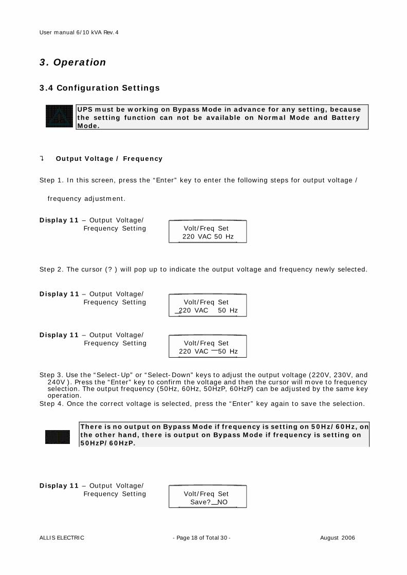
3. Operation 3.4 Configuration Settings
UPS must be working on Bypass Mode in advance for any setting, because the setting function can not be available on Normal Mode and Battery Mode.
? Output Voltage / Frequency
Step 1. In this screen, press the “Enter” key to enter the following steps for output voltage /
frequency adjustment.
Display 11 – Output Voltage/ Frequency Setting Volt/Freq Set 220 VAC 50 Hz Step 2. The cursor (? ) will pop up to indicate the output voltage and frequency newly selected. Display 11 – Output Voltage/ Frequency Setting Volt/Freq Set 220 VAC 50 Hz Display 11 – Output Voltage/ Frequency Setting Volt/Freq Set 220 VAC 50 Hz Step 3. Use the “Select-Up” or “Select-Down” keys to adjust the output voltage (220V, 230V, and
240V ). Press the “Enter” key to confirm the voltage and then the cursor will move to frequency selection. The output frequency (50Hz, 60Hz, 50HzP, 60HzP) can be adjusted by the same key operation.
Step 4. Once the correct voltage is selected, press the “Enter” key again to save the selection. Display 11 – Output Voltage/ Frequency Setting Volt/Freq Set Save? NO
There is no output on Bypass Mode if frequency is setting on 50Hz/60Hz, on the other hand, there is output on Bypass Mode if frequency is setting on 50HzP/60HzP.
User manual 6/10 kVA Rev.4
ALLIS ELECTRIC - Page 19 of Total 30 - August 2006
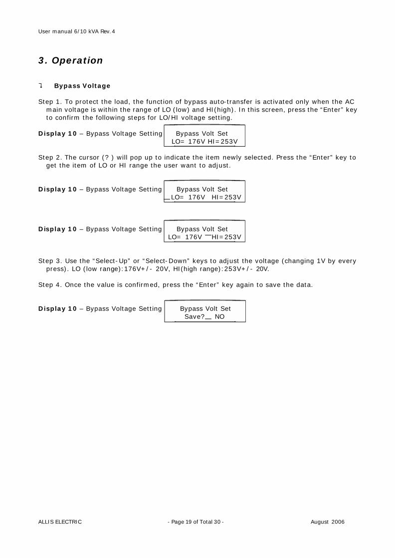
3. Operation ? Bypass Voltage Step 1. To protect the load, the function of bypass auto-transfer is activated only when the AC
main voltage is within the range of LO (low) and HI(high). In this screen, press the “Enter” key to confirm the following steps for LO/HI voltage setting.
Display 10 – Bypass Voltage Setting Bypass Volt Set LO= 176V HI=253V Step 2. The cursor (? ) will pop up to indicate the item newly selected. Press the “Enter” key to
get the item of LO or HI range the user want to adjust. Display 10 – Bypass Voltage Setting Bypass Volt Set LO= 176V HI=253V Display 10 – Bypass Voltage Setting Bypass Volt Set LO= 176V HI=253V Step 3. Use the “Select-Up” or “Select-Down” keys to adjust the voltage (changing 1V by every
press). LO (low range):176V+/- 20V, HI(high range):253V+/- 20V. Step 4. Once the value is confirmed, press the “Enter” key again to save the data. Display 10 – Bypass Voltage Setting Bypass Volt Set Save? NO
User manual 6/10 kVA Rev.4
ALLIS ELECTRIC - Page 20 of Total 30 - August 2006
4. Maintenance 4.1 General Maintenance
The Star T3 Series UPS requires very simple maintenance. The batteries are sealed, valve-regulated, maintenance-free and enclosed in a fire-retardant pack. The batteries should be kept charged to maintain their designed lifetime. When utility power is supplied to the UPS, it will continuously charge the batteries.
? Environment
? For the best preventive maintenance, keep the area around the UPS clean and dust-free.
? Please keep the exhaust holes of UPS unobstructed. ? Operate the UPS in an indoor environment with an ambient temperature range of 32°F
to +104°F (0°C to +40°C). ? Keep the UPS on a flat, stable surface with 50cm space around it for proper ventilation. ? Do not place the unit near a heat source and avoid placing the unit in direct sunlight. ? Do not place the unit near water or excessive moisture.
? Storing the UPS and Battery
When storing the UPS for any length of time, it is recommended to plug in the UPS for at least 24 hours every four to six months to ensure full battery recharge.
? Replace the Battery
It is suggested that the battery pack be replaced every two years to ensure that the UPS provides full backup capacity during a blackout. Batteries should be checked every two to three months. If the batteries need replacing, please contact your sales representative to order a new battery.
User manual 6/10 kVA Rev.4
ALLIS ELECTRIC - Page 21 of Total 30 - August 2006
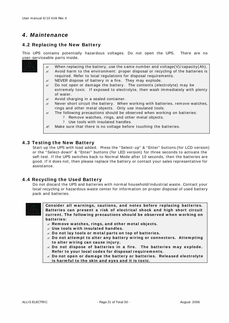
4. Maintenance 4.2 Replacing the New Battery
This UPS contains potentially hazardous voltages. Do not open the UPS. There are no user-serviceable parts inside.
4.3 Testing the New Battery
Start up the UPS with load added. Press the “Select-up” & “Enter” buttons (for LCD version) or the “Select-down” & “Enter” buttons (for LED version) for three seconds to activate the self-test. If the UPS switches back to Normal Mode after 10 seconds, then the batteries are good. If it does not, then please replace the battery or contact your sales representative for assistance.
4.4 Recycling the Used Battery
Do not discard the UPS and batteries with normal household/industrial waste. Contact your local recycling or hazardous waste center for information on proper disposal of used battery pack and batteries.
Consider all warnings, cautions, and notes before replacing batteries. Batteries can present a risk of electrical shock and high short circuit current. The following precautions should be observed when working on batteries: ? Remove watches, rings, and other metal objects. ? Use tools with insulated handles. ? Do not lay tools or metal parts on top of batteries. ? Do not attempt to alter any battery wiring or connectors. Attempting
to alter wiring can cause injury. ? Do not dispose of batteries in a fire. The batteries may explode.
Refer to your local codes for disposal requirements. ? Do not open or damage the battery or batteries. Released electrolyte
is harmful to the skin and eyes and it is toxic.
? When replacing the battery, use the same number and voltage(V)/capacity(Ah). ? Avoid harm to the environment: proper disposal or recycling of the batteries is
required. Refer to local regulations for disposal requirements. ? NEVER dispose of battery in a fire. They may explode. ? Do not open or damage the battery. The contents (electrolyte) may be
extremely toxic. If exposed to electrolyte, then wash immediately with plenty of water.
? Avoid charging in a sealed container. ? Never short circuit the battery. When working with batteries, remove watches,
rings and other metal objects. Only use insulated tools. ? The following precautions should be observed when working on batteries:
? Remove watches, rings, and other metal objects. ? Use tools with insulated handles.
? Make sure that there is no voltage before touching the batteries.
User manual 6/10 kVA Rev.4
ALLIS ELECTRIC - Page 22 of Total 30 - August 2006
4. Maintenance 4.5 Maintenance Bypass ? Switch to bypass 1. In case of performing service or maintenance on the UPS or bypass the LOAD from the UPS,
a Maintenance Bypass Switch can be operated located at the back of the UPS. 2. Turn the UPS into internal bypass mode by pressing the Up ‘? ’ and Down ‘? ’ arrow keys
together. 3. Ensure the UPS has gone into ‘Bypass Mode’ by checking from the display. 4. Unscrew the cover to reveal the Maintenance Bypass Switch. 5. Rotate the switch to ‘Bypass’ ? Return from bypass to normal mode 1. Ensure the UPS is in ‘Bypass Mode’ referring step 1 of section 3.2 Start UP of the UPS, and
check from the display. If the UPS is in ‘Normal Mode’ switch it to ‘Bypass Mode’ by pressing the Up ‘? ’ and Down ‘? ’ arrow keys together.
2. Rotate the Maintenance Bypass Switch to ‘UPS’ position. 3. Reattach the Maintenance Bypass Switch cover. (Note: the inverter will not start with this
cover off the unit.) 4. Restart the Inverter (UPS) referring step 2 of section 3.2 Start UP of the UPS.
? Bypass switch not to be operated if the UPS is in ‘Battery Mode’! ? IF THE FOLLOWING PROCEDURE IS NOT FOLLOWED EXACTLY THE LOAD ON
THE OUTPUT OF THE UPS MAY BE INTERUPTED AND THE UPS MAY BE DAMAGED.
User manual 6/10 kVA Rev.4
ALLIS ELECTRIC - Page 23 of Total 30 - August 2006
5. Troubleshooting ? LCD
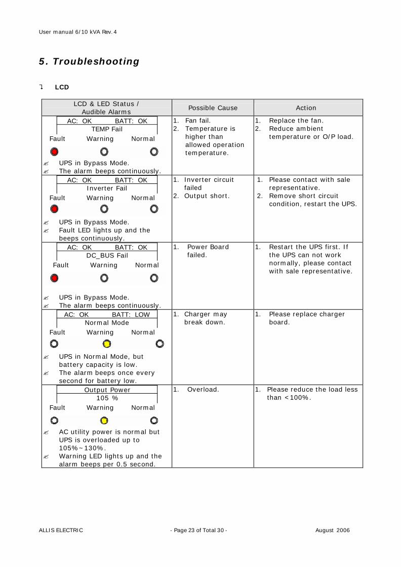
LCD & LED Status / Audible Alarms
Possible Cause Action
Fault Warning Normal ? UPS in Bypass Mode. ? The alarm beeps continuously.
AC: OK BATT: OK TEMP Fail
1. Fan fail. 2. Temperature is
higher than allowed operation temperature.
1. Replace the fan. 2. Reduce ambient
temperature or O/P load.
Fault Warning Normal ? UPS in Bypass Mode. ? Fault LED lights up and the
beeps continuously.
AC: OK BATT: OK Inverter Fail
1. Inverter circuit failed
2. Output short.
1. Please contact with sale representative.
2. Remove short circuit condition, restart the UPS.
Fault Warning Normal ? UPS in Bypass Mode. ? The alarm beeps continuously.
AC: OK BATT: OK DC_BUS Fail
1. Power Board failed.
1. Restart the UPS first. If the UPS can not work normally, please contact with sale representative.
Fault Warning Normal ? UPS in Normal Mode, but
battery capacity is low. ? The alarm beeps once every
second for battery low.
AC: OK BATT: LOW Normal Mode
1. Charger may break down.
1. Please replace charger board.
Fault Warning Normal ? AC utility power is normal but
UPS is overloaded up to 105%~130%.
? Warning LED lights up and the alarm beeps per 0.5 second.
Output Power 105 %
1. Overload. 1. Please reduce the load less than <100%.
User manual 6/10 kVA Rev.4
ALLIS ELECTRIC - Page 24 of Total 30 - August 2006
5. Troubleshooting
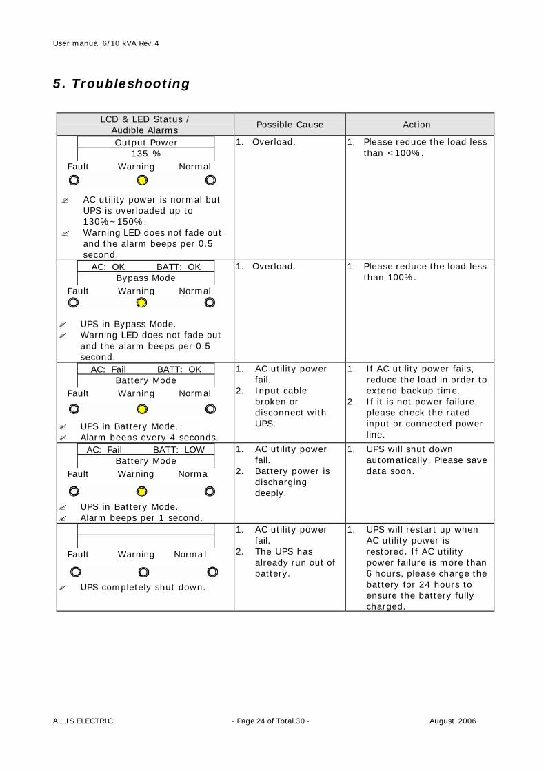
LCD & LED Status / Audible Alarms
Possible Cause Action
Fault Warning Normal ? AC utility power is normal but
UPS is overloaded up to 130%~150%.
? Warning LED does not fade out and the alarm beeps per 0.5 second.
Output Power 135 %
1. Overload. 1. Please reduce the load less than <100%.
Fault Warning Normal ? UPS in Bypass Mode. ? Warning LED does not fade out
and the alarm beeps per 0.5 second.
AC: OK BATT: OK Bypass Mode
1. Overload. 1. Please reduce the load less than 100%.
Fault Warning Normal ? UPS in Battery Mode. ? Alarm beeps every 4 seconds.
AC: Fail BATT: OK Battery Mode
1. AC utility power fail.
2. Input cable broken or disconnect with UPS.
1. If AC utility power fails, reduce the load in order to extend backup time.
2. If it is not power failure, please check the rated input or connected power line.
Fault Warning Norma ? UPS in Battery Mode. ? Alarm beeps per 1 second.
AC: Fail BATT: LOW Battery Mode
1. AC utility power fail.
2. Battery power is discharging deeply.
1. UPS will shut down automatically. Please save data soon.
Fault Warning Normal ? UPS completely shut down.
1. AC utility power fail.
2. The UPS has already run out of battery.
1. UPS will restart up when AC utility power is restored. If AC utility power failure is more than 6 hours, please charge the battery for 24 hours to ensure the battery fully charged.
User manual 6/10 kVA Rev.4
ALLIS ELECTRIC - Page 25 of Total 30 - August 2006
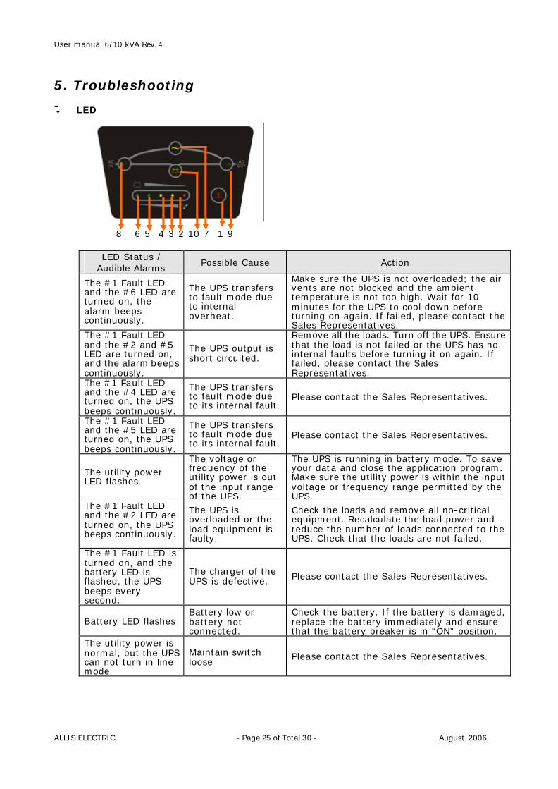
5. Troubleshooting ? LED 8 6 5 4 3 2 10 7 1 9
LED Status / Audible Alarms
Possible Cause Action
The #1 Fault LED and the #6 LED are turned on, the alarm beeps continuously.
The UPS transfers to fault mode due to internal overheat.
Make sure the UPS is not overloaded; the air vents are not blocked and the ambient temperature is not too high. Wait for 10 minutes for the UPS to cool down before turning on again. If failed, please contact the Sales Representatives.
The #1 Fault LED and the #2 and #5 LED are turned on, and the alarm beeps continuously.
The UPS output is short circuited.
Remove all the loads. Turn off the UPS. Ensure that the load is not failed or the UPS has no internal faults before turning it on again. If failed, please contact the Sales Representatives.
The #1 Fault LED and the #4 LED are turned on, the UPS beeps continuously.
The UPS transfers to fault mode due to its internal fault.
Please contact the Sales Representatives.
The #1 Fault LED and the #5 LED are turned on, the UPS beeps continuously.
The UPS transfers to fault mode due to its internal fault.
Please contact the Sales Representatives.
The utility power LED flashes.
The voltage or frequency of the utility power is out of the input range of the UPS.
The UPS is running in battery mode. To save your data and close the application program. Make sure the utility power is within the input voltage or frequency range permitted by the UPS.
The #1 Fault LED and the #2 LED are turned on, the UPS beeps continuously.
The UPS is overloaded or the load equipment is faulty.
Check the loads and remove all no-critical equipment. Recalculate the load power and reduce the number of loads connected to the UPS. Check that the loads are not failed.
The #1 Fault LED is turned on, and the battery LED is flashed, the UPS beeps every second.
The charger of the UPS is defective. Please contact the Sales Representatives.
Battery LED flashes Battery low or battery not connected.
Check the battery. If the battery is damaged, replace the battery immediately and ensure that the battery breaker is in “ON” position.
The utility power is normal, but the UPS can not turn in line mode
Maintain switch loose
Please contact the Sales Representatives.
User manual 6/10 kVA Rev.4
ALLIS ELECTRIC - Page 26 of Total 30 - August 2006
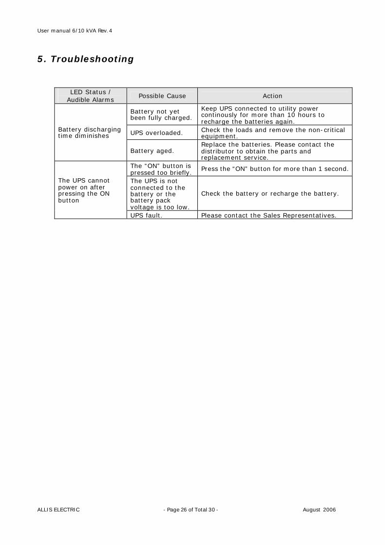
5. Troubleshooting
LED Status / Audible Alarms
Possible Cause Action
Battery not yet been fully charged.
Keep UPS connected to utility power continously for more than 10 hours to recharge the batteries again.
UPS overloaded. Check the loads and remove the non-critical equipment.
Battery discharging time diminishes
Battery aged. Replace the batteries. Please contact the distributor to obtain the parts and replacement service.
The “ON” button is pressed too briefly.
Press the “ON” button for more than 1 second.
The UPS is not connected to the battery or the battery pack voltage is too low.
Check the battery or recharge the battery.
The UPS cannot power on after pressing the ON button
UPS fault. Please contact the Sales Representatives.
User manual 6/10 kVA Rev.4
ALLIS ELECTRIC - Page 27 of Total 30 - August 2006
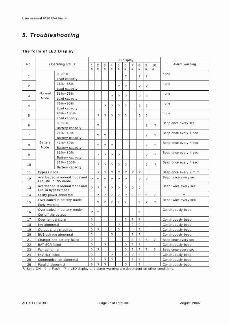
5. Troubleshooting The form of LED Display
LED display No. Operating status 1
# 2#
3#
4#
5#
6#
7#
8#
9#
10#
Alarm warning
1 0~35%
Load capacity ? ? ?
none
2 36%~55%
Load capacity ? ? ? ?
none
3 56%~75%
Load capacity ? ? ? ? ?
none
4 76%~95%
Load capacity ? ? ? ? ? ?
none
5
Normal
Mode
96%~105%
Load capacity ? ? ? ? ? ? ?
none
6 0~20%
Battery capacity ? ? ?
Beep once every sec
7 21%~40%
Battery capacity ? ? ? ?
Beep once every 4 sec
8 41%~60%
Battery capacity ? ? ? ? ?
Beep once every 4 sec
9 61%~80%
Battery capacity ? ? ? ? ? ?
Beep once every 4 sec
10
Battery
Mode
81%~100%
Battery capacity ? ? ? ? ? ? ?
Beep once every 4 sec
11 Bypass mode ? ? ? ? ? ? ? Beep once every 2 min.
12 overloaded in normal mode and UPS still in INV mode
? ? ? ? ? ? ? ? Beep twice every sec.
13 overloaded in normal mode and UPS in bypass mode
? ? ? ? ? ? ? ? Beep twice every sec.
14 Utility power abnormal ? ? ? ? ? ? ? ? ? ?
15 Overloaded in battery mode,
Early-warning ? ? ? ? ? ? ? ?
Beep twice every sec.
16 Overloaded in battery mode,
Cut off the output ? ? ?
Continuously beep
17 Over temperature ? ? ? ? Continuously beep
18 Inv abnormal ? ? ? ? Continuously beep
19 Output short circuited ? ? ? ? Continuously beep
20 BUS voltage abnormal ? ? ? ? Continuously beep
21 Charger and battery failed ? ? ? ? ? Beep once every sec
22 BAT SCR failed ? ? ? ? ? Continuously beep
23 Fan abnormal ? ? ? ? ? ? ? Beep once every sec
24 INV RLY failed ? ? ? ? ? Continuously beep
25 Communication abnormal ? ? ? ? ? Continuously beep
26 Parallel abnormal ? ? ? ? ? Continuously beep ?: Solid ON ? : Flash ? : LED display and alarm warning are dependent on other conditions.
User manual 6/10 kVA Rev.4
ALLIS ELECTRIC - Page 28 of Total 30 - August 2006
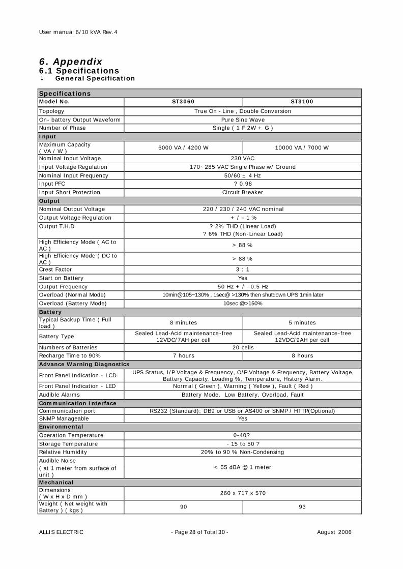
6. Appendix 6.1 Specifications ? General Specification Specifications Model No. ST3060 ST3100
Topology True On - Line , Double Conversion
On- battery Output Waveform Pure Sine Wave Number of Phase Single ( 1 F 2W + G )
Input Maximum Capacity ( VA / W )
6000 VA / 4200 W 10000 VA / 7000 W
Nominal Input Voltage 230 VAC
Input Voltage Regulation 170~285 VAC Single Phase w/ Ground
Nominal Input Frequency 50/60 ± 4 Hz Input PFC ? 0.98
Input Short Protection Circuit Breaker
Output Nominal Output Voltage 220 / 230 / 240 VAC nominal
Output Voltage Regulation + / - 1 %
Output T.H.D ? 2% THD (Linear Load) ? 6% THD (Non-Linear Load) High Efficiency Mode ( AC to AC )
> 88 %
High Efficiency Mode ( DC to AC )
> 88 %
Crest Factor 3 : 1
Start on Battery Yes
Output Frequency 50 Hz + / - 0.5 Hz Overload (Normal Mode) 10min@105~130% , 1sec@ >130% then shutdown UPS 1min later
Overload (Battery Mode) 10sec @>150%
Battery Typical Backup Time ( Full load )
8 minutes 5 minutes
Battery Type Sealed Lead-Acid maintenance-free 12VDC/7AH per cell
Sealed Lead-Acid maintenance-free 12VDC/9AH per cell
Numbers of Batteries 20 cells Recharge Time to 90% 7 hours 8 hours
Advance Warning Diagnostics
Front Panel Indication - LCD UPS Status, I/P Voltage & Frequency, O/P Voltage & Frequency, Battery Voltage, Battery Capacity, Loading %, Temperature, History Alarm.
Front Panel Indication - LED Normal ( Green ), Warning ( Yellow ), Fault ( Red )
Audible Alarms Battery Mode, Low Battery, Overload, Fault
Communication Interface Communication port RS232 (Standard); DB9 or USB or AS400 or SNMP / HTTP(Optional) SNMP Manageable Yes Environmental
Operation Temperature 0-40?
Storage Temperature - 15 to 50 ? Relative Humidity 20% to 90 % Non-Condensing
Audible Noise ( at 1 meter from surface of unit )
< 55 dBA @ 1 meter
Mechanical Dimensions ( W x H x D mm )
260 x 717 x 570
Weight ( Net weight with Battery ) ( kgs )
90 93
User manual 6/10 kVA Rev.4
ALLIS ELECTRIC - Page 29 of Total 30 - August 2006
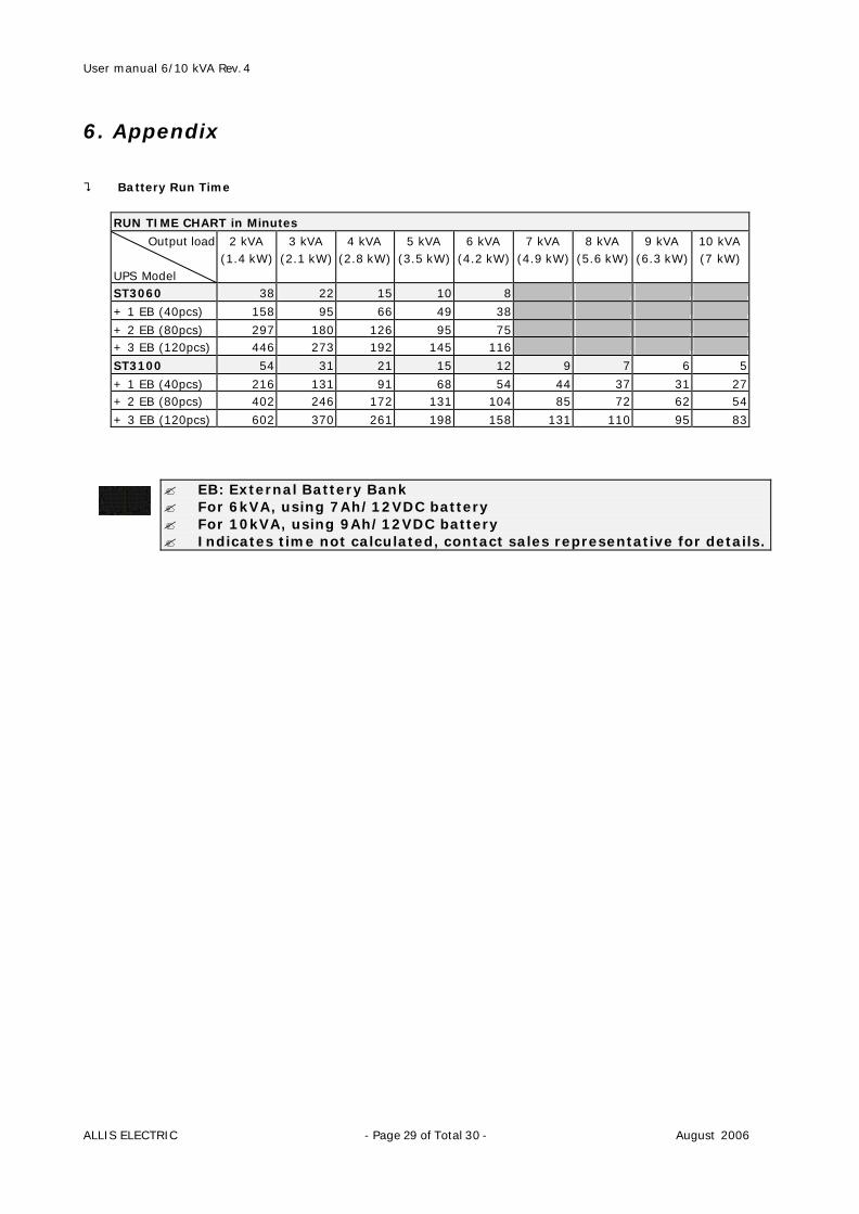
6. Appendix ? Battery Run Time
RUN TIME CHART in Minutes
Output load UPS Model
2 kVA (1.4 kW)
3 kVA (2.1 kW)
4 kVA (2.8 kW)
5 kVA (3.5 kW)
6 kVA (4.2 kW)
7 kVA (4.9 kW)
8 kVA (5.6 kW)
9 kVA (6.3 kW)
10 kVA (7 kW)
ST3060 38 22 15 10 8
+ 1 EB (40pcs) 158 95 66 49 38
+ 2 EB (80pcs) 297 180 126 95 75 + 3 EB (120pcs) 446 273 192 145 116
ST3100 54 31 21 15 12 9 7 6 5
+ 1 EB (40pcs) 216 131 91 68 54 44 37 31 27 + 2 EB (80pcs) 402 246 172 131 104 85 72 62 54
+ 3 EB (120pcs) 602 370 261 198 158 131 110 95 83
? EB: External Battery Bank ? For 6kVA, using 7Ah/12VDC battery ? For 10kVA, using 9Ah/12VDC battery ? Indicates time not calculated, contact sales representative for details.
User manual 6/10 kVA Rev.4
ALLIS ELECTRIC - Page 30 of Total 30 - August 2006
6. Appendix 6.2 Contact Information
Asia Allis Electric Co., Ltd. 12th F1., No.19-11, San-Chung Road, Nan Kang District, Taipei 115, Taiwan R.O.C. Tel:886-2-2655-3456 Fax:886-2-2655-2286~7 E-mail:[email protected] http://www.allis.com.tw Sheen Asia Electronics Co., Ltd. 2F, Building A2, Beiwei Industrial Area, GETDD, Guangzhou, People's Republic of China, 510730 Tel:+86-20-8222 1370/1 Fax:+86-20-8222-1419 E-mail:[email protected] http://www.sheenasia.com
North America IMP Enterprises, inc. 18218 East McDurmott, Suite E, Irvine, California 92614, U.S.A Tel:+1-949-477-9198 Fax:+1-949-477-9195 E-mail: [email protected] http://www.impenterprises.com
Europe
AEC SpA Via Vesuvio 1 I-20054 NOVA MILANESE MI, Italy Tel:+39-0362364535 Fax:+39-02-700-427499 +39 0362366059 E-mail: [email protected] http://www.aeceuro.com
AEC Power Control Ltd. Systems House, Eckington Business Park, Rotherside Road, Derbyshire, S21 4HL. Tel: +44 (0)1246 439861 Fax: +44 (0)1246 431444 E-mail: [email protected] http://www.aeceuro.co.uk