Embed Size (px)
Citation preview
User Manual UNIBLITZ VMM-D3 Three Channel Shutter Driver and
VMM-D4 Four Channel Shutter Driver
14-0030 Version 1.1 2003
2
Vincent Associates products are covered by U.S. patents. Information in this publication supercedes that in all previously published material. Due to our ongoing development program, Vincent Associates reserves to right to discontinue or change specifications or designs, at any time, without incurring any obligation. Printed in the U.S.A. Ver. 1.1 2003 Vincent Associates, a Division of VA, Inc., 803 Linden Ave., Rochester, NY 14625 Tel: 585-385-5930 Fax: 585-385-6004 UNIBLITZ is a registered trademark of VA, Inc.
3
WARRANTY
Great care has been taken to ensure that our products are free from defect when shipped. Defective units will be replaced or repaired at no charge, excepting transportation charges, if returned within one year from the date of original shipment. This offer does not apply to burned out actuator coils and/or blown fuses. Vincent Associates will consider the return of unused equipment if returned within 30 days from the date of shipment, subject to a 20% restocking charge. This offer does not apply to used or damaged equipment. This warranty extends only to the original purchaser and is not available to any third party, including any purchaser assemblies, or other products of which the goods may become component equipment.

4
Following is the complete operators manual for the UNIBLITZ VMM-D3 and VMM-D4. Please read this manual completely before operating your unit. Due to the construction of these units, we recommend that they be returned to the manufacturer for repair, no user serviceable parts inside.

5
General Safety Summary
Review the following safety precautions to avoid injury and prevent damage to this product or any products connected to it. To avoid potential hazards, use the product only as specified.
Only qualified personnel should perform service procedures.
Injury Precautions
• Use proper Power Cord – To avoid fire hazard, use only the power cord supplied with this product.
• Avoid Electric Overload – To avoid electrical shock or fire hazard, do not apply a voltage to a terminal that is outside the range specified for that terminal.
• Avoid Electric Shock – To avoid injury or loss of life, do not connect or disconnect line cord while it is connected to the line voltage.
• Ground the Product – This product is grounded through the grounding conductor of the power cord. To avoid electrical shock, the grounding connector must be connected to earth ground. Before making connections to the input or output terminals of the product, ensure that the product is properly grounded. DO NOT DEFEAT THE GROUND CONNECTION ON THE SUPPLIED LINE CORD.
• Do Not Operate Without Covers – To avoid electric shock or fire hazard, do not operate this product with case or panels removed.
• Use Proper Fuse – To avoid fire hazard, use only the fuse type and rating specified for this product.
• Do Not operate in Wet/Damp Conditions – To avoid electric shock, do not operate this product in wet or damp conditions.
• Do Not Operate in an Explosive Atmosphere – To avoid injury or fire hazard, do not operate this product in an explosive atmosphere.
Product Damage Precautions
• Use Proper Power Source – Do not operate this product from a power source that applies more than the voltage specified.
• Provide Proper Ventilation – To prevent product overheating, provide proper ventilation.
• Do Not Operate with Suspected Failures – If you suspect there is damage to this product, have it inspected by qualified service personnel.
6
Start Up After unpacking your unit inspect for any defects. If upon
inspection a problem is found, or a part (or parts) are missing, notify Vincent Associates immediately.
After the initial inspection the unit is ready to use. To properly install and power on the VMM-D3 or VMM-D4, perform this procedure. 1. Check that you have the proper electrical connections. The rear label,
which covers the AC input module, is there to remind you to manually configure the AC input module if the unit requires operation at 230VAC. See “Voltage Change” instructions. THIS LABEL MUST BE REMOVED PRIOR TO INSERTING THE POWER CORD INTO THE AC INPUT CONNECTOR REGARDLESS OF WHICH AC VOLTAGE LEVEL IS USED.
2. Check the line fuses to be sure they are the proper rating. The VMM-D3 and VMM-D4 have been shipped with the proper fuses for 115VAC operation (3AG .5A time-lag). For 230VAC operation, change line fuses to the 5mm x 20mm .25A time-lag (supplied w/unit, packaged separately). See “Line Fuse Replacement” instructions.
3. Be sure the AC module power switch is toggled to the “0” position and the power end of the line cord is not connected to the AC line. Then connect the opposite end of the supplied line cord to the rear panel AC module connector. Be sure the cord is inserted completely into the AC module connector.
4. Connect the power end of the line cord to the AC line. Power unit ON by toggling the AC module power switch to the “1” position. Power LED indicator will illuminate.
Line Fuse Replacement
1. Have handy a small flat-bladed screwdriver or similar tool and refer to Figure #1.
2. Set the VMM-D3 or VMM-D4 unit so that the rear panel is facing you.
3. BE SURE THE LINE CORD IS DISCONNECTED FROM THE LINE VOLTAGE POWER SOURCE. Unplug the line cord from the AC module connector. You cannot proceed with this procedure without removing the line cord from the VMM-D3/D4 control unit.
WARNING. To avoid injury or death, unplug the line cord from the line voltage power source before continuing.
7
4. Using the small flat bladed screwdriver or similar tool; insert the tool into the cover door slot; pry open cover door.
5. Using the same tool; insert the tool into the fuse holder slot; pry out the fuse holder block.
6. Remove defective fuse(s); replace with new fuse(s) and replace fuse holder into housing; close the cover door.
Voltage Change
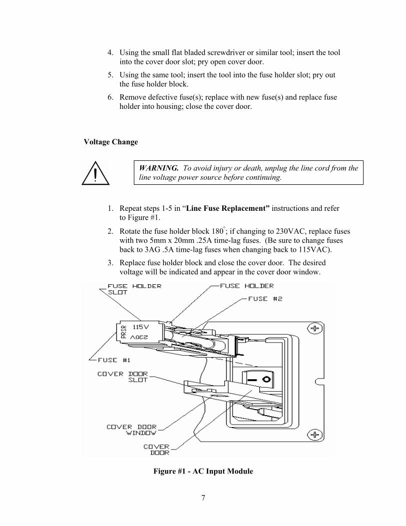
1. Repeat steps 1-5 in “Line Fuse Replacement” instructions and refer to Figure #1.
2. Rotate the fuse holder block 180°; if changing to 230VAC, replace fuses with two 5mm x 20mm .25A time-lag fuses. (Be sure to change fuses back to 3AG .5A time-lag fuses when changing back to 115VAC).
3. Replace fuse holder block and close the cover door. The desired voltage will be indicated and appear in the cover door window.
Figure #1 - AC Input Module
WARNING. To avoid injury or death, unplug the line cord from the line voltage power source before continuing.
8
VMM-D3/D4 Three/Four Channel Shutter Driver Description
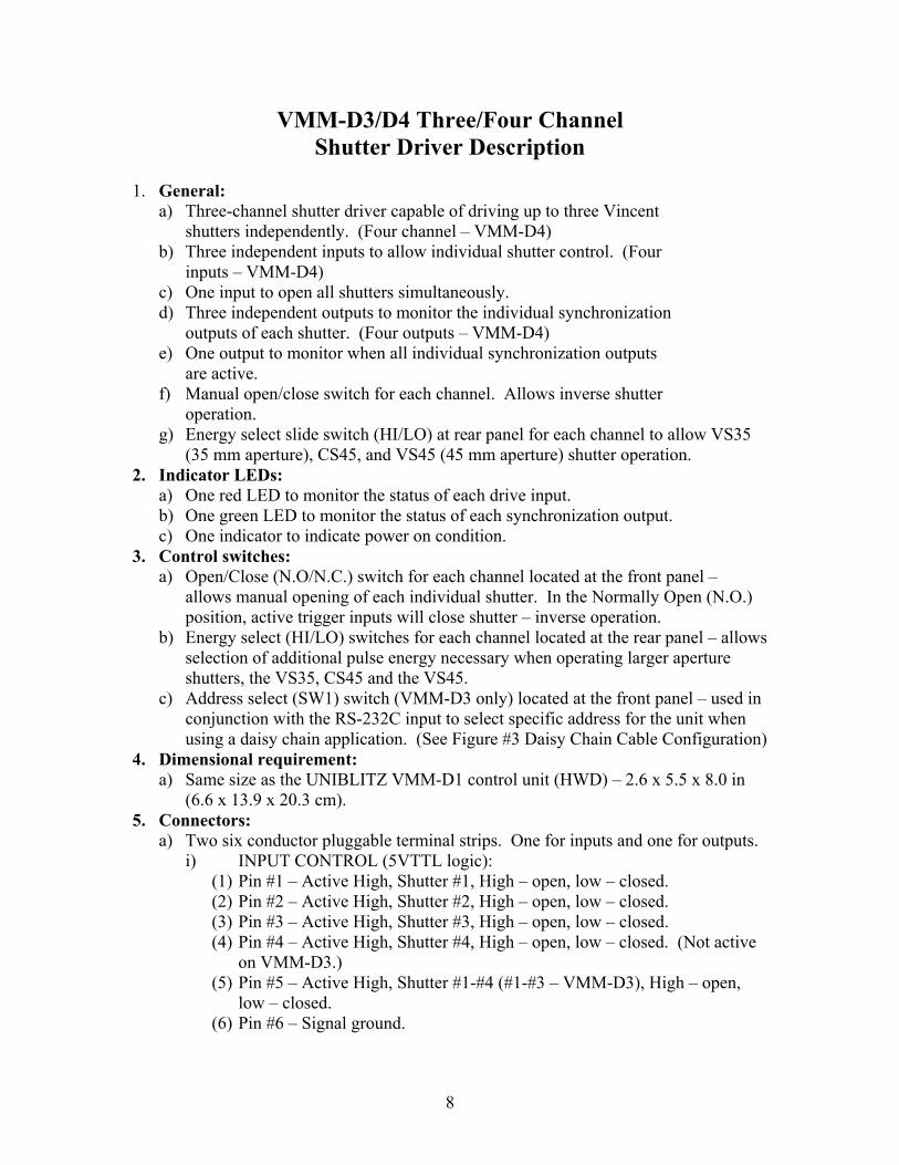
1. General:
a) Three-channel shutter driver capable of driving up to three Vincent shutters independently. (Four channel – VMM-D4)
b) Three independent inputs to allow individual shutter control. (Four inputs – VMM-D4)
c) One input to open all shutters simultaneously. d) Three independent outputs to monitor the individual synchronization
outputs of each shutter. (Four outputs – VMM-D4) e) One output to monitor when all individual synchronization outputs
are active. f) Manual open/close switch for each channel. Allows inverse shutter
operation. g) Energy select slide switch (HI/LO) at rear panel for each channel to allow VS35
(35 mm aperture), CS45, and VS45 (45 mm aperture) shutter operation. 2. Indicator LEDs:
a) One red LED to monitor the status of each drive input. b) One green LED to monitor the status of each synchronization output. c) One indicator to indicate power on condition.
3. Control switches: a) Open/Close (N.O/N.C.) switch for each channel located at the front panel –
allows manual opening of each individual shutter. In the Normally Open (N.O.) position, active trigger inputs will close shutter – inverse operation.
b) Energy select (HI/LO) switches for each channel located at the rear panel – allows selection of additional pulse energy necessary when operating larger aperture shutters, the VS35, CS45 and the VS45.
c) Address select (SW1) switch (VMM-D3 only) located at the front panel – used in conjunction with the RS-232C input to select specific address for the unit when using a daisy chain application. (See Figure #3 Daisy Chain Cable Configuration)
4. Dimensional requirement: a) Same size as the UNIBLITZ VMM-D1 control unit (HWD) – 2.6 x 5.5 x 8.0 in
(6.6 x 13.9 x 20.3 cm). 5. Connectors:
a) Two six conductor pluggable terminal strips. One for inputs and one for outputs. i) INPUT CONTROL (5VTTL logic):
(1) Pin #1 – Active High, Shutter #1, High – open, low – closed. (2) Pin #2 – Active High, Shutter #2, High – open, low – closed. (3) Pin #3 – Active High, Shutter #3, High – open, low – closed. (4) Pin #4 – Active High, Shutter #4, High – open, low – closed. (Not active
on VMM-D3.) (5) Pin #5 – Active High, Shutter #1-#4 (#1-#3 – VMM-D3), High – open,
low – closed. (6) Pin #6 – Signal ground.
9
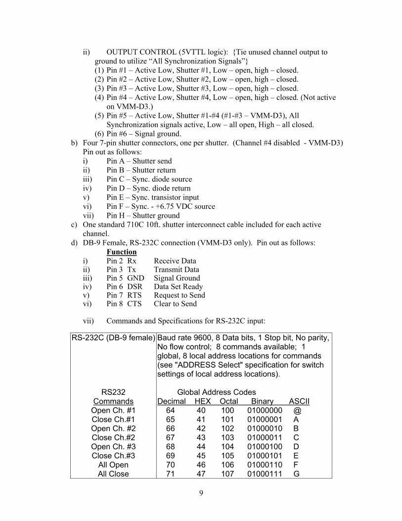
ii) OUTPUT CONTROL (5VTTL logic): {Tie unused channel output to ground to utilize “All Synchronization Signals”} (1) Pin #1 – Active Low, Shutter #1, Low – open, high – closed. (2) Pin #2 – Active Low, Shutter #2, Low – open, high – closed. (3) Pin #3 – Active Low, Shutter #3, Low – open, high – closed. (4) Pin #4 – Active Low, Shutter #4, Low – open, high – closed. (Not active
on VMM-D3.) (5) Pin #5 – Active Low, Shutter #1-#4 (#1-#3 – VMM-D3), All
Synchronization signals active, Low – all open, High – all closed. (6) Pin #6 – Signal ground.
b) Four 7-pin shutter connectors, one per shutter. (Channel #4 disabled - VMM-D3) Pin out as follows: i) Pin A – Shutter send ii) Pin B – Shutter return iii) Pin C – Sync. diode source iv) Pin D – Sync. diode return v) Pin E – Sync. transistor input vi) Pin F – Sync. - +6.75 VDC source vii) Pin H – Shutter ground
c) One standard 710C 10ft. shutter interconnect cable included for each active channel.
d) DB-9 Female, RS-232C connection (VMM-D3 only). Pin out as follows: Function i) Pin 2 Rx Receive Data ii) Pin 3 Tx Transmit Data iii) Pin 5 GND Signal Ground iv) Pin 6 DSR Data Set Ready v) Pin 7 RTS Request to Send vi) Pin 8 CTS Clear to Send
vii) Commands and Specifications for RS-232C input:
RS-232C (DB-9 female) Baud rate 9600, 8 Data bits, 1 Stop bit, No parity, No flow control; 8 commands available; 1 global, 8 local address locations for commands (see "ADDRESS Select" specification for switch settings of local address locations).
RS232 Global Address Codes
Commands Decimal HEX Octal Binary ASCII Open Ch. #1 64 40 100 01000000 @ Close Ch.#1 65 41 101 01000001 A Open Ch. #2 66 42 102 01000010 B Close Ch.#2 67 43 103 01000011 C Open Ch. #3 68 44 104 01000100 D Close Ch.#3 69 45 105 01000101 E
All Open 70 46 106 01000110 F All Close 71 47 107 01000111 G
10
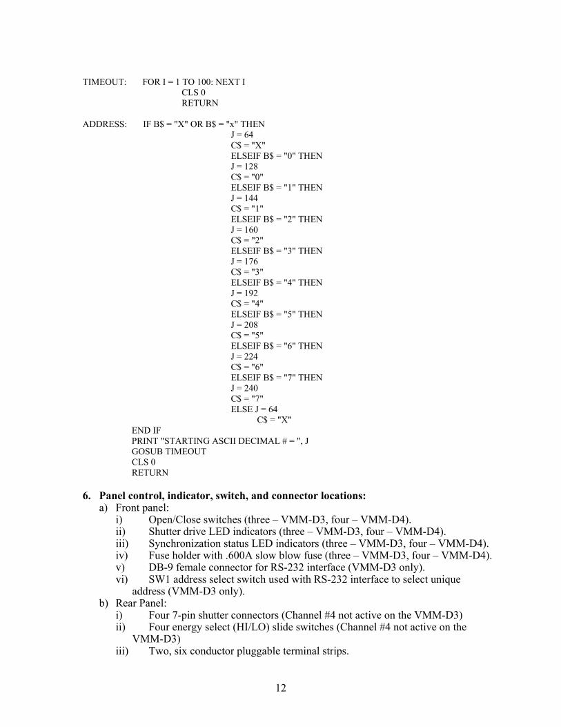
viii) RS-232 Test Program for the VMM-D3 REM PROGRAM TO SEND COMMAND PULSES TO VMM-D3 RS232 INTERFACE, XILINX CPLD. REM WRITTEN BY RICHARD ST.LOUIS, VINCENT ASSOCIATES. REM LAST REVISION 8/2/99. CLS 0 K = -1 WHILE K OPEN "COM1:9600,N,8,1,CS0,DS0" FOR RANDOM AS #1 J = 64 C$ = "X" MENU: PRINT PRINT PRINT PRINT "WAITING FOR KEYSTROKE COMMAND " PRINT "TYPE:" PRINT " VMM-D3 " PRINT " ------ " PRINT " O - OPEN Ch. 1 " PRINT " C - CLOSE Ch. 1 " PRINT " P - OPEN Ch. 2 " PRINT " L - CLOSE Ch. 2 " PRINT " N - OPEN Ch. 3 " PRINT " E - CLOSE Ch. 3 " PRINT " A - ALL Ch.'s OPEN " PRINT " R - ALL Ch.'s CLOSE " PRINT PRINT " S - SET Octal Switch Address " PRINT " (Current Starting Decimal # ="; J; ")" PRINT " (Current Octal Address Value = "; C$; ")" PRINT PRINT " Q - QUIT Program "
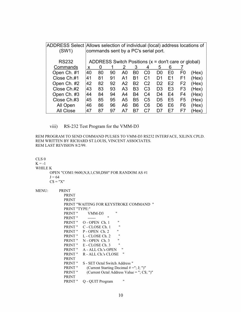
ADDRESS Select (SW1)
Allows selection of individual (local) address locations of commands sent by a PC's serial port.
RS232 ADDRESS Switch Positions (x = don't care or global) Commands x 0 1 2 3 4 5 6 7
Open Ch. #1 40 80 90 A0 B0 C0 D0 E0 F0 (Hex) Close Ch.#1 41 81 91 A1 B1 C1 D1 E1 F1 (Hex) Open Ch. #2 42 82 92 A2 B2 C2 D2 E2 F2 (Hex) Close Ch.#2 43 83 93 A3 B3 C3 D3 E3 F3 (Hex) Open Ch. #3 44 84 94 A4 B4 C4 D4 E4 F4 (Hex) Close Ch.#3 45 85 95 A5 B5 C5 D5 E5 F5 (Hex)
All Open 46 86 96 A6 B6 C6 D6 E6 F6 (Hex) All Close 47 87 97 A7 B7 C7 D7 E7 F7 (Hex)

11
PRINT PRINT START: A$ = INKEY$ IF A$ = "O" OR A$ = "o" THEN PRINT #1, CHR$(J); PRINT "Ch. 1 OPEN COMMAND SENT" GOSUB TIMEOUT GOTO MENU ELSEIF A$ = "C" OR A$ = "c" THEN PRINT #1, CHR$(J + 1); PRINT "Ch. 1 CLOSE COMMAND SENT" GOSUB TIMEOUT GOTO MENU ELSEIF A$ = "P" OR A$ = "p" THEN PRINT #1, CHR$(J + 2); PRINT "Ch. 2 OPEN COMMAND SENT" GOSUB TIMEOUT GOTO MENU ELSEIF A$ = "L" OR A$ = "l" THEN PRINT #1, CHR$(J + 3); PRINT "Ch. 2 CLOSE COMMAND SENT" GOSUB TIMEOUT GOTO MENU ELSEIF A$ = "N" OR A$ = "n" THEN PRINT #1, CHR$(J + 4); PRINT "Ch. 3 OPEN COMMAND SENT" GOSUB TIMEOUT GOTO MENU ELSEIF A$ = "E" OR A$ = "e" THEN PRINT #1, CHR$(J + 5); PRINT "Ch. 3 CLOSE COMMAND SENT" GOSUB TIMEOUT GOTO MENU ELSEIF A$ = "A" OR A$ = "a" THEN PRINT #1, CHR$(J + 6); PRINT "ALL Ch.'s OPEN COMMAND SENT" GOSUB TIMEOUT GOTO MENU ELSEIF A$ = "R" OR A$ = "r" THEN PRINT #1, CHR$(J + 7); PRINT "ALL Ch.'s CLOSE COMMAND SENT" GOSUB TIMEOUT GOTO MENU ELSEIF A$ = "Q" OR A$ = "q" THEN K = 0 PRINT "PROGRAM TERMINATED" ELSEIF A$ = "S" OR A$ = "s" THEN INPUT "ENTER OCTAL ADDRESS 0 - 7 or X: ", B$ GOSUB ADDRESS GOTO MENU ELSE GOTO START END IF WEND END
12
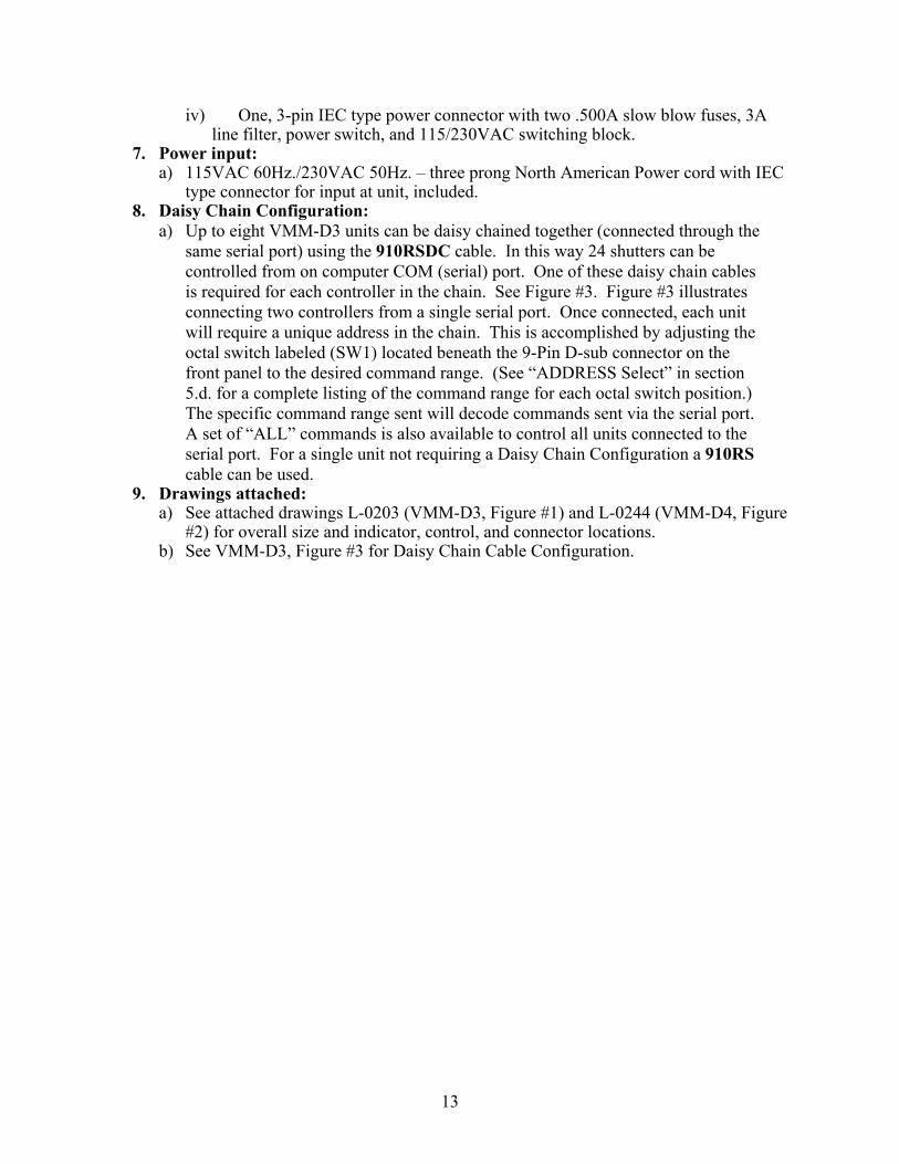
TIMEOUT: FOR I = 1 TO 100: NEXT I CLS 0 RETURN ADDRESS: IF B$ = "X" OR B$ = "x" THEN J = 64 C$ = "X" ELSEIF B$ = "0" THEN J = 128 C$ = "0" ELSEIF B$ = "1" THEN J = 144 C$ = "1" ELSEIF B$ = "2" THEN J = 160 C$ = "2" ELSEIF B$ = "3" THEN J = 176 C$ = "3" ELSEIF B$ = "4" THEN J = 192 C$ = "4" ELSEIF B$ = "5" THEN J = 208 C$ = "5" ELSEIF B$ = "6" THEN J = 224 C$ = "6" ELSEIF B$ = "7" THEN J = 240 C$ = "7" ELSE J = 64 C$ = "X" END IF PRINT "STARTING ASCII DECIMAL # = ", J GOSUB TIMEOUT CLS 0 RETURN 6. Panel control, indicator, switch, and connector locations:
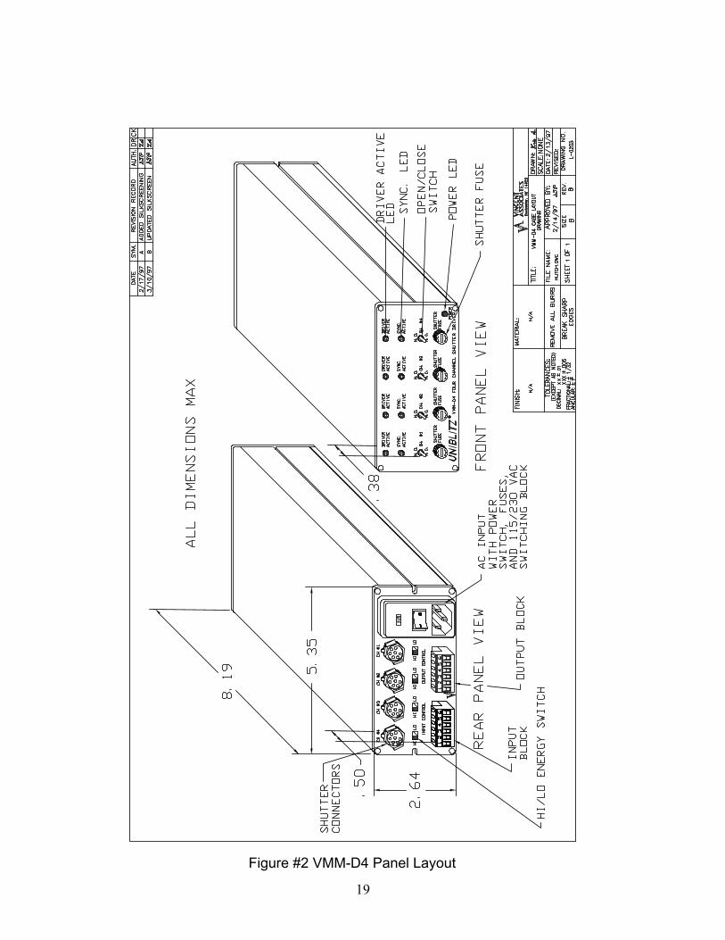
a) Front panel: i) Open/Close switches (three – VMM-D3, four – VMM-D4). ii) Shutter drive LED indicators (three – VMM-D3, four – VMM-D4). iii) Synchronization status LED indicators (three – VMM-D3, four – VMM-D4). iv) Fuse holder with .600A slow blow fuse (three – VMM-D3, four – VMM-D4). v) DB-9 female connector for RS-232 interface (VMM-D3 only). vi) SW1 address select switch used with RS-232 interface to select unique
address (VMM-D3 only). b) Rear Panel:
i) Four 7-pin shutter connectors (Channel #4 not active on the VMM-D3) ii) Four energy select (HI/LO) slide switches (Channel #4 not active on the
VMM-D3) iii) Two, six conductor pluggable terminal strips.
13
iv) One, 3-pin IEC type power connector with two .500A slow blow fuses, 3A line filter, power switch, and 115/230VAC switching block.
7. Power input: a) 115VAC 60Hz./230VAC 50Hz. – three prong North American Power cord with IEC
type connector for input at unit, included. 8. Daisy Chain Configuration:
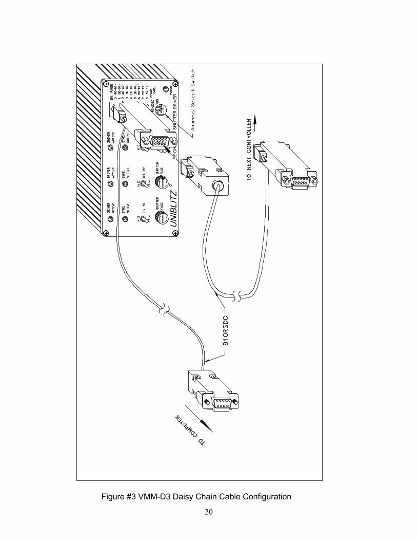
a) Up to eight VMM-D3 units can be daisy chained together (connected through the same serial port) using the 910RSDC cable. In this way 24 shutters can be controlled from on computer COM (serial) port. One of these daisy chain cables is required for each controller in the chain. See Figure #3. Figure #3 illustrates connecting two controllers from a single serial port. Once connected, each unit will require a unique address in the chain. This is accomplished by adjusting the octal switch labeled (SW1) located beneath the 9-Pin D-sub connector on the front panel to the desired command range. (See “ADDRESS Select” in section 5.d. for a complete listing of the command range for each octal switch position.) The specific command range sent will decode commands sent via the serial port. A set of “ALL” commands is also available to control all units connected to the serial port. For a single unit not requiring a Daisy Chain Configuration a 910RS cable can be used.
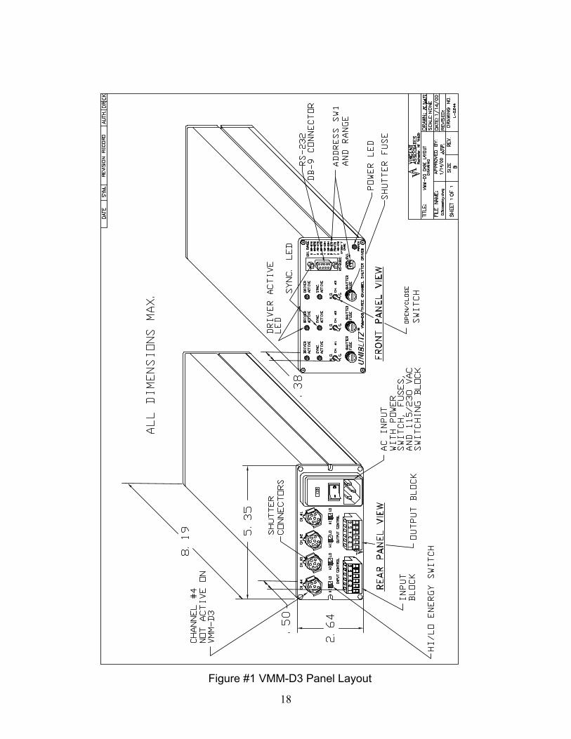
9. Drawings attached: a) See attached drawings L-0203 (VMM-D3, Figure #1) and L-0244 (VMM-D4, Figure
#2) for overall size and indicator, control, and connector locations. b) See VMM-D3, Figure #3 for Daisy Chain Cable Configuration.
14
SPECIFICATIONS
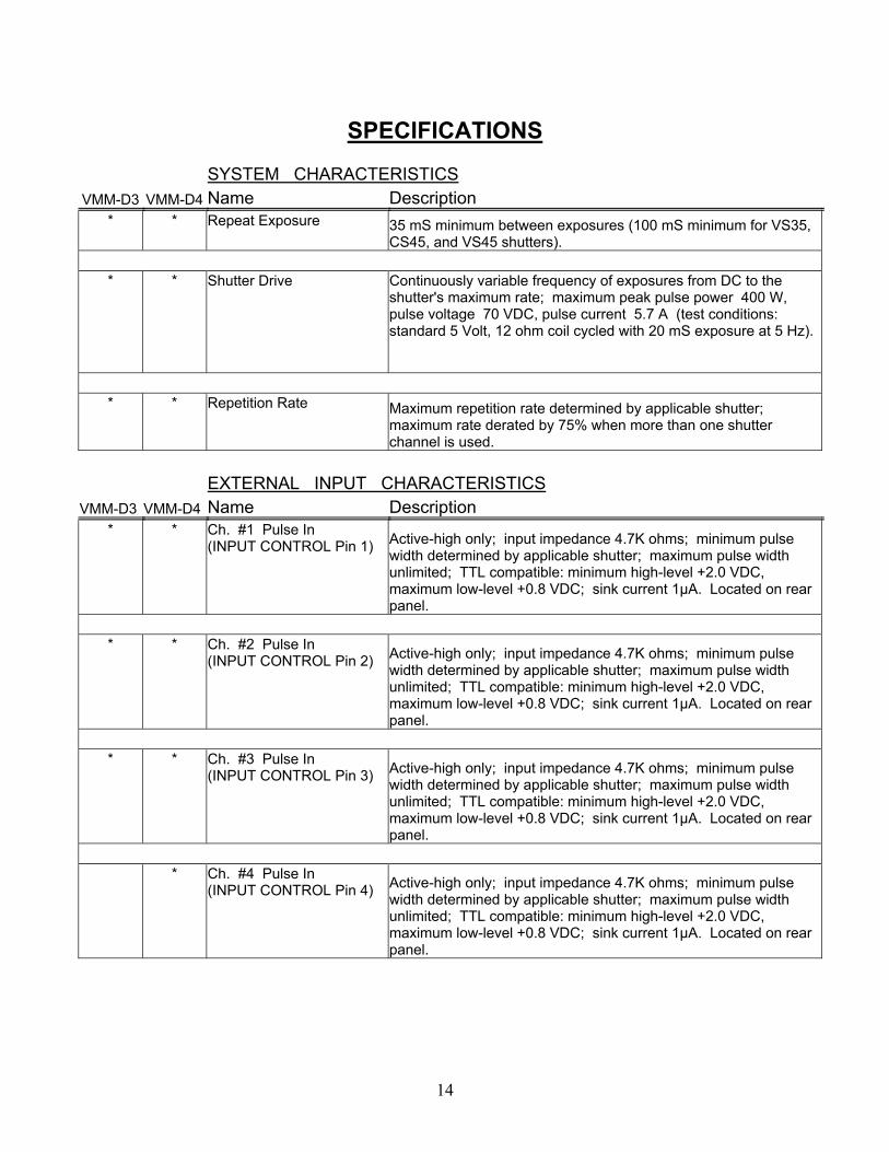
SYSTEM CHARACTERISTICS VMM-D3 VMM-D4 Name Description
* * Repeat Exposure 35 mS minimum between exposures (100 mS minimum for VS35, CS45, and VS45 shutters).
* * Shutter Drive Continuously variable frequency of exposures from DC to the
shutter's maximum rate; maximum peak pulse power 400 W, pulse voltage 70 VDC, pulse current 5.7 A (test conditions: standard 5 Volt, 12 ohm coil cycled with 20 mS exposure at 5 Hz).
* * Repetition Rate Maximum repetition rate determined by applicable shutter;
maximum rate derated by 75% when more than one shutter channel is used.
EXTERNAL INPUT CHARACTERISTICS VMM-D3 VMM-D4 Name Description
* * Ch. #1 Pulse In (INPUT CONTROL Pin 1) Active-high only; input impedance 4.7K ohms; minimum pulse
width determined by applicable shutter; maximum pulse width unlimited; TTL compatible: minimum high-level +2.0 VDC, maximum low-level +0.8 VDC; sink current 1µA. Located on rear panel.
* * Ch. #2 Pulse In
(INPUT CONTROL Pin 2) Active-high only; input impedance 4.7K ohms; minimum pulse width determined by applicable shutter; maximum pulse width unlimited; TTL compatible: minimum high-level +2.0 VDC, maximum low-level +0.8 VDC; sink current 1µA. Located on rear panel.
* * Ch. #3 Pulse In
(INPUT CONTROL Pin 3) Active-high only; input impedance 4.7K ohms; minimum pulse width determined by applicable shutter; maximum pulse width unlimited; TTL compatible: minimum high-level +2.0 VDC, maximum low-level +0.8 VDC; sink current 1µA. Located on rear panel.
* Ch. #4 Pulse In
(INPUT CONTROL Pin 4) Active-high only; input impedance 4.7K ohms; minimum pulse width determined by applicable shutter; maximum pulse width unlimited; TTL compatible: minimum high-level +2.0 VDC, maximum low-level +0.8 VDC; sink current 1µA. Located on rear panel.
15
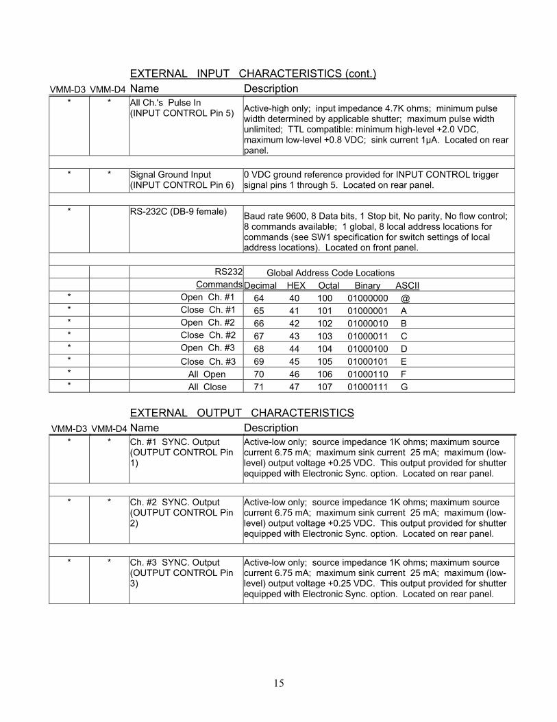
EXTERNAL INPUT CHARACTERISTICS (cont.) VMM-D3 VMM-D4 Name Description
* * All Ch.'s Pulse In (INPUT CONTROL Pin 5) Active-high only; input impedance 4.7K ohms; minimum pulse
width determined by applicable shutter; maximum pulse width unlimited; TTL compatible: minimum high-level +2.0 VDC, maximum low-level +0.8 VDC; sink current 1µA. Located on rear panel.
* * Signal Ground Input
(INPUT CONTROL Pin 6) 0 VDC ground reference provided for INPUT CONTROL trigger signal pins 1 through 5. Located on rear panel.
* RS-232C (DB-9 female) Baud rate 9600, 8 Data bits, 1 Stop bit, No parity, No flow control;
8 commands available; 1 global, 8 local address locations for commands (see SW1 specification for switch settings of local address locations). Located on front panel.
RS232 Global Address Code Locations Commands Decimal HEX Octal Binary ASCII * Open Ch. #1 64 40 100 01000000 @ * Close Ch. #1 65 41 101 01000001 A * Open Ch. #2 66 42 102 01000010 B * Close Ch. #2 67 43 103 01000011 C * Open Ch. #3 68 44 104 01000100 D * Close Ch. #3 69 45 105 01000101 E * All Open 70 46 106 01000110 F * All Close 71 47 107 01000111 G
EXTERNAL OUTPUT CHARACTERISTICS VMM-D3 VMM-D4 Name Description
* * Ch. #1 SYNC. Output (OUTPUT CONTROL Pin 1)
Active-low only; source impedance 1K ohms; maximum source current 6.75 mA; maximum sink current 25 mA; maximum (low-level) output voltage +0.25 VDC. This output provided for shutter equipped with Electronic Sync. option. Located on rear panel.
* * Ch. #2 SYNC. Output
(OUTPUT CONTROL Pin 2)
Active-low only; source impedance 1K ohms; maximum source current 6.75 mA; maximum sink current 25 mA; maximum (low-level) output voltage +0.25 VDC. This output provided for shutter equipped with Electronic Sync. option. Located on rear panel.
* * Ch. #3 SYNC. Output
(OUTPUT CONTROL Pin 3)
Active-low only; source impedance 1K ohms; maximum source current 6.75 mA; maximum sink current 25 mA; maximum (low-level) output voltage +0.25 VDC. This output provided for shutter equipped with Electronic Sync. option. Located on rear panel.
16
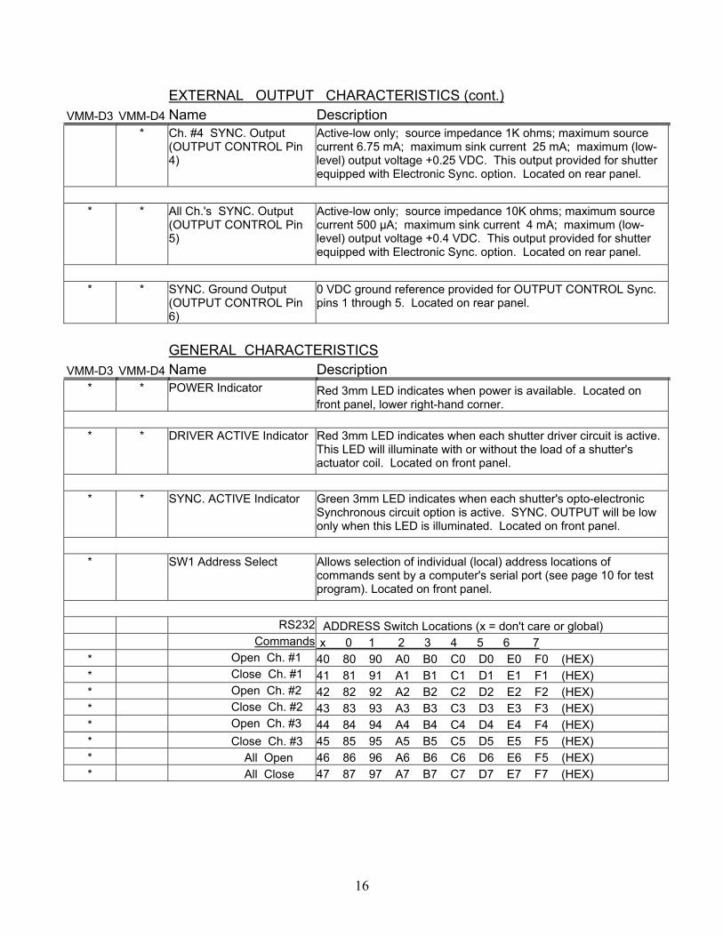
EXTERNAL OUTPUT CHARACTERISTICS (cont.) VMM-D3 VMM-D4 Name Description
* Ch. #4 SYNC. Output (OUTPUT CONTROL Pin 4)
Active-low only; source impedance 1K ohms; maximum source current 6.75 mA; maximum sink current 25 mA; maximum (low-level) output voltage +0.25 VDC. This output provided for shutter equipped with Electronic Sync. option. Located on rear panel.
* * All Ch.'s SYNC. Output
(OUTPUT CONTROL Pin 5)
Active-low only; source impedance 10K ohms; maximum source current 500 µA; maximum sink current 4 mA; maximum (low-level) output voltage +0.4 VDC. This output provided for shutter equipped with Electronic Sync. option. Located on rear panel.
* * SYNC. Ground Output
(OUTPUT CONTROL Pin 6)
0 VDC ground reference provided for OUTPUT CONTROL Sync. pins 1 through 5. Located on rear panel.
GENERAL CHARACTERISTICS VMM-D3 VMM-D4 Name Description
* * POWER Indicator Red 3mm LED indicates when power is available. Located on front panel, lower right-hand corner.
* * DRIVER ACTIVE Indicator Red 3mm LED indicates when each shutter driver circuit is active.
This LED will illuminate with or without the load of a shutter's actuator coil. Located on front panel.
* * SYNC. ACTIVE Indicator Green 3mm LED indicates when each shutter's opto-electronic
Synchronous circuit option is active. SYNC. OUTPUT will be low only when this LED is illuminated. Located on front panel.
* SW1 Address Select Allows selection of individual (local) address locations of
commands sent by a computer's serial port (see page 10 for test program). Located on front panel.
RS232 ADDRESS Switch Locations (x = don't care or global) Commands x 0 1 2 3 4 5 6 7 * Open Ch. #1 40 80 90 A0 B0 C0 D0 E0 F0 (HEX) * Close Ch. #1 41 81 91 A1 B1 C1 D1 E1 F1 (HEX) * Open Ch. #2 42 82 92 A2 B2 C2 D2 E2 F2 (HEX) * Close Ch. #2 43 83 93 A3 B3 C3 D3 E3 F3 (HEX) * Open Ch. #3 44 84 94 A4 B4 C4 D4 E4 F4 (HEX) * Close Ch. #3 45 85 95 A5 B5 C5 D5 E5 F5 (HEX) * All Open 46 86 96 A6 B6 C6 D6 E6 F5 (HEX) * All Close 47 87 97 A7 B7 C7 D7 E7 F7 (HEX)
17
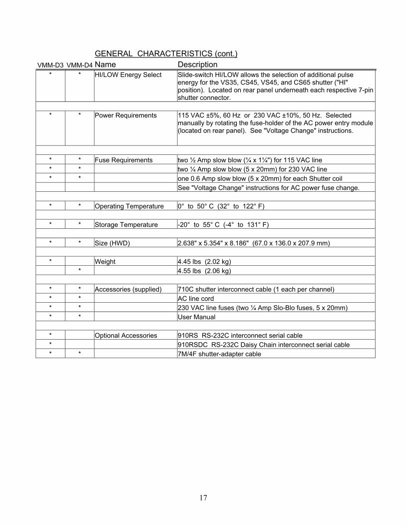
GENERAL CHARACTERISTICS (cont.) VMM-D3 VMM-D4 Name Description
* * HI/LOW Energy Select Slide-switch HI/LOW allows the selection of additional pulse energy for the VS35, CS45, VS45, and CS65 shutter ("HI" position). Located on rear panel underneath each respective 7-pin shutter connector.
* * Power Requirements 115 VAC ±5%, 60 Hz or 230 VAC ±10%, 50 Hz. Selected
manually by rotating the fuse-holder of the AC power entry module (located on rear panel). See "Voltage Change" instructions.
* * Fuse Requirements two ½ Amp slow blow (¼ x 1¼") for 115 VAC line * * two ¼ Amp slow blow (5 x 20mm) for 230 VAC line * * one 0.6 Amp slow blow (5 x 20mm) for each Shutter coil See "Voltage Change" instructions for AC power fuse change.
* * Operating Temperature 0° to 50° C (32° to 122° F)
* * Storage Temperature -20° to 55° C (-4° to 131° F)
* * Size (HWD) 2.638" x 5.354" x 8.186" (67.0 x 136.0 x 207.9 mm)
* Weight 4.45 lbs (2.02 kg)
* 4.55 lbs (2.06 kg)
* * Accessories (supplied) 710C shutter interconnect cable (1 each per channel) * * AC line cord * * 230 VAC line fuses (two ¼ Amp Slo-Blo fuses, 5 x 20mm) * * User Manual
* Optional Accessories 910RS RS-232C interconnect serial cable * 910RSDC RS-232C Daisy Chain interconnect serial cable * * 7M/4F shutter-adapter cable
18
Figure #1 VMM-D3 Panel Layout
19
Figure #2 VMM-D4 Panel Layout
20
RE
E C
H
SH
UTT
ER
DR
IVE
R
Figure #3 VMM-D3 Daisy Chain Cable Configuration

21
NOTES