Embed Size (px)
Citation preview
user's guide to
Readyfor AVR
box version

I want to express my thanks to you for being interested in our products and for having
confidence in Mikroelektronika.
The primary aim of our company is to design and produce high quality electronic products
and to constantly improve the performance thereof in order to better suit your needs.
The Microchip, Atmel, NXP and CYPRESS name, logo and products names are trademarks of Microchip, Atmel, NXP and CYPRESS Inc. in the U.S.A and other countries.
TO OUR VALUED CUSTOMERS
Nebojsa Matic
General Manager

Page 3
Ready for AVR board Introduction 4
System Specification 5
Components 6
1. Power supply 8
6. External Oscillator 9
4. ATmega16 microcontroller 10
5. Programming the microcontroller 11
Programming with mikroBootloader 12
step 1 – Connecting 12
step 2 - Connecting 13
step 3 - Browsing for .hex file 13
step 4 - Browsing for .hex file 14
step 5 - uploading .hex file 14
step 6 - Finish upload 15
Programing with AVRProg™ programmer 16
6. USB-UART 18
7. Port headers 19
8. General Purpose Area 20
9. Integrating with the casing 21
10. Dimensions 22
Table of Contents

Page 4
Ready for AVR board Introduction
Ready for AVR Board is the best
solution for fast and simple development
of various microcontroller applications. It
comes with ATmega16 that is placed in
DIP40B socket. It is preprogrammed with
UART bootloader, so you don’t have to
use external programmers to program the
microcontroller. Board contains double-
row IDC10 headers for all available
microcontroller ports. It also contains
USB-UART module, prototyping area and
a power supply circuit. Board is specially
designed to fit into special white plastic
casing so you can turn your cool AVR
project into a final product.

Page 5
System Specification
power supply
Via AC/DC connector 7-23V AC
or 9-32V DC
board dimensions
14 x 8,2cm (5.51 x 3.23 inch)
weight
~69g (0.15 lbs)
power consumption
50mA in idle state
(when on-board modules are off)

Page 6
Components
01
02
03
04
05
06
07
08
09
10
11
12
1213
14
15
AVRProg™ connector
Power LED indicator
8MHz external oscillator
DIP40A socket
UART comm. LEDs (RX, TX)
FTDI chip
USB UART connector
Power connector
Power screw terminals
IDC10 PORT header
Power regulator
Reset button
ATmega16 microcontroller
Prototyping area
Mounting holes

Page 7
01 02
15 14
03
13
0504 06 07
12
08
11 10
09

Page 8 Page 9
1. Power supply
Figure 1-1: AC/DC adapter power
supply connected
Figure 1-3: USB connected
Figure 1-2: laboratory power supply
connected to screw terminalsVCC
VCCD6
MBRS140T3
L1
220uHVCC-EXT
D2
1N4007
D4
1N4007
D3
1N4007
D5
1N4007
VCC
7-23V AC9-32V DC
POWP POWN
E5330uF/6V
E4330uF/35V
R100.22
R22K2
R73K
R81K
C9220pF
LD1A
CN8
CN7
1
2
3
4
8
7
6
5
SWC
SWE
CT
GND
DRVC
IPK
VIN
CMPR
U4
MC34063APOWER
Figure 1-4: Schematics of external power supply
Ready for AVR board can be powered in two ways: over USB
connection, or using external power sources, such as adapters,
or laboratory power supplys. USB connection can provide up to
500mA of current, which is more than enough for evey on-board
module and for operation of the microcontroller. If you decide
to use external power supply, you can choose bewteen AC/DC
adapter connector or power screw terminals . Voltage and current
values must be within 7-23V AC or 9-32V DC ranges. Power LED
will indicate the presence of current. Use only one method for
powering the board.

Page 9
C2100nF
VCC
C10100nF
VCC
C13100nF
123456789
1011121314151617181920 21
22232425262728293031323334353637383940
U2
DIP40B
123456789
1011121314151617181920 21
22232425262728293031323334353637383940
U1
DIP40A
VCC
PA0PA1PA2PA3PA4PA5PA6PA7PE0
OSCPC0PC1PC2PC3
PD0PD1
PD7PD6PD5PD4PD3PD2
PB4PB3PB2PB1PB0
PC7PC6PC5PC4
PE1PE2
PB5-MOSI
PB7-SCKPB6-MISO
mRST#
OSCPD0PD1
PD7PD6PD5PD4PD3PD2
PB4PB3PB2PB1PB0 PA0
PA1PA2PA3PA4PA5PA6PA7
PC0PC1PC2PC3
PC7PC6PC5PC4
AREF
PB5-MOSI
PB7-SCKPB6-MISO
mRST#
VCC AVCC
C11100nF
VCC AVCCFP2
FERRITE1110
U3E
74HC04
56U3C
74HC04 R131K
C322pF
C422pF
R12
1M
X1 8 MHz
OSC
12U3A
74HC04
34U3B
74HC04
98U3D
74HC04
1312U3F
74HC04
C1100nF
VCC
DATA BUS
6. External Oscillator
Board contains 8MHz external crystal oscillator
which delivers the clock necessary for the
operation of microcontroller. Raw clock signal from
the crystal is sinusoidal, so additional 74HC04 is
provided which filters it to create square signal
necessary for stable operation.
Figure 6-2:External clock module
Figure 6-1:External Oscillator schematics

Page 10 Page 11
4. ATmega16 microcontroller
Key microcontroller features - Up to 16 MIPS Operation;
- 8-bit architecture;
– 16 KB of Flash program memory;
- 1 KB of internal SRAM memory;
- 512 Bytes of EEPROM
- 32 I/O pins;
- UART, SPI, ADC; etc.
- JTAG DEBUGING interface
PORTADRIVERS
BUFFERS
PORTADIGITALINTERFACE
PORTCDRIVERS
BUFFERS
PORTCDIGITALINTERFACE
PORTBDRIVERS
BUFFERS
PORTBDIGITALINTERFACE
PORTDDRIVERS
BUFFERS
PORTDDIGITALINTERFACE
TIMERSCOUNTERS
TWI
WATCHDOGTIMER
EEPROM
USART
INTERUPTUNIT
INSTRUCTIONDECODER
ADC
FLASH
SRAM
SPI
COMP.INTERFACE
AVRCPU
DA
TA B
US
Ready for AVR development system comes with the ATmega16 microcontroller.
Having lots of MIPS power, flash and RAM, and rich set inegrated modules, ATmega16
is ideal choice for both beginners and professionals.
Page 11
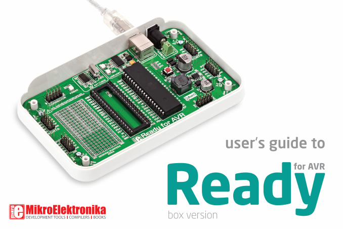
The microcontroller can be programmed in two ways:
5. Programming the microcontroller
01
02
Over USB-UART mikroBootloader
Using JTAG external programmer
Figure 5-1: ATmega16

Programming with mikroBootloader
You can program the microcontroller with bootloader which is
preprogrammed into the device by default. To transfer .hex file
from a PC to MCU you need bootloader software (mikroBootloader
USB HID) which can be downloaded from:
After software is downloaded unzip it to desired location and
start mikroBootloader USB HID software.
http://www.mikroe.com/eng/downloads/get/1652/mikrobootloader_atmega16_v100.zip
step 1 – Connecting01
02
03
Start mikroBootloader
Click the Change Settings button.
In Setup window, select appropriate COM port. Click OK.
Figure 5-2: UART mikroBootloader
02
03
This version of mikroBootloader is for AVR
microcontrollers only.
note

step 2 - Connecting step 3 - Browsing for .hex file
02
01
Figure 5-3: Browse for HEX Figure 5-4: Browse for HEX
01 01
02
Press reset button on Ready board.
Click Connect button within 5s, otherwise existing microcontroller program will execute.
Click on Browse for HEX button.

step 4 - Browsing for .hex file step 5 - uploading .hex file
Figure 5-5: Locating and Selecting .hex file Figure 5-6: Begin uploading
01 01
02
Select .hex file via open dialog window.
Click on Open button.
To start .hex file uploading click on Begin uploading button.
01
02
01

step 6 - Finish upload
01 01
Figure 5-7: Progress bar Figure 5-8: Browse for HEX
01 01
02
You can monitor .hex file uploading via progress bar. Click OK button.
Press Reset button on Ready board and wait for 5 seconds. Your program will execute automaticly.

Page 16
Ready for AVR board contains IDC10 male
headers for connecting AVRprog™ external
USB 2.0 programmer. When connecting,
make sure to orient the programmer
connector so that first pins on both male
and female header connectors align. Correct
connector placement is shown on Figure
5-9.
Programing with AVRProg™
programmer
Figure 5-9:AVRProg™ connected to Ready for AVR board

Page 17
Figure 5-10: AVRprog™ connector schematics
C2100nF
VCC
C13100nF
123456789
1011121314151617181920 21
22232425262728293031323334353637383940
U2
DIP40B
123456789
1011121314151617181920 21
22232425262728293031323334353637383940
U1
DIP40A
VCC
PA0PA1PA2PA3PA4PA5PA6PA7PE0
OSCPC0PC1PC2PC3
PD0PD1
PD7PD6PD5PD4PD3PD2
PB4PB3PB2PB1PB0
PC7PC6PC5PC4
PE1PE2
PB5-MOSI
PB7-SCKPB6-MISO
mRST#
OSCPD0PD1
PD7PD6PD5PD4PD3PD2
PB4PB3PB2PB1PB0 PA0
PA1PA2PA3PA4PA5PA6PA7
PC0PC1PC2PC3
PC7PC6PC5PC4
AREF
PB5-MOSI
PB7-SCKPB6-MISO
mRST#
VCC
C10100nF
VCC
AVCC
C11100nF
VCC AVCCFP2
FERRITE
AVRpro
gCON
NECTOR
VCC
PB5-MOSI
PB7-SCKPB6-MISO
mRST#
CN6

Page 18
6. USB-UART
C5100nF
C6100nF
E310uF
VCC VCC-FTDIVCC-FTDI
C7100nF
VCC-USB
USBDMUSBDP
C8100nF
VCC
VCC VCC
RX-LEDTX-LED
PD0
PD1
RX-MCU
TX-MCU
VCC-FTDI
123456789
1011121314 15
16171819202122232425262728
TXDDTR#RTS#VCCIORXDRI#GNDNCDSR#DCD#CTS#CBUS4CBUS2CBUS3
CBUS0CBUS1
OSCOOSCITEST
AGNDNC
GND
GND
VCCRESET#
3V3OUTUSBDMUSBDP
FT232RL
U5
D1MBRS140T3FP1
FERRITE
VCC
LD2A LD3B
R32K2
R42K2
RX TX
1
2
3
4
VCC
GND
D-
D+
CN9
USB B
12
J2
12
J3
USBDM
USBDP
DAT
A B
US
Figure 6-2: USB cable connected
Figure 6-1: USB-UART module schematics
Fast on-board FTDI chip allows you to communicate with a PC or other UART devices using USB-UART
connection. Female USB Type-B connector (CN9) is used for connecting the USB cable. RX and TX
LEDs will indicate communication status. Before connecting the board with the PC, make sure to
have the appropriate FTDI drivers installed on your operating system. Drivers can be found
at following URL: http://www.ftdichip.com/Drivers/VCP.htm

Page 19
VCC
VCC
VCC
VCC
PA0 PA1PA2 PA3PA4 PA5
PC0
PA6
PC1PC3
PA7
PC2
PC7PC6PC5PC4
PD0
PD6PD5PD4PD3PD1
PD2
PD7PB4
PB3PB2PB1PB0
PB5PB7PB6
R6 100
R9 100
R11 100
PB5-MOSI
PB6-MISO
PB7-SCK
PB5
PB6
PB7VCC
PE0 PE1PE2
CN1
CN2
CN3
CN4
CN5
DATA BUS7. Port headersEach microcontroller pin is available for futher connections through on-board
connection headers. Pins are clearly marked which makes them easier to
interface. IDC10 headers are compatible with over 70 additional boards from
mikroElektronika, so you can easily add new features to the base Ready for
AVR board.
Figure 7-1: Port headers connection schematics
Figure 7-2: Accessory board connected

Page 20
8. General Purpose Area
General Purpose Area
allows you to expand your
Ready for AVR board with
additional functionalities,
by placing your additional
components into available
soldering pads. Pads are
arranged in standard 100mil
distance form factor. There
are 12 connected lines on
both halfs of the breadboard
area, and each line consists
of 4 soldering pads. 8x8
matrix of unconnected sol-
de ring pads are located in
the lower section. VCC and
GND lines are also availble
on the ending sides of the
entire breadboard area.
Figure 8-1: General purpose area

Page 21
9. Integrating with the casing
Figure 9-1: Integrating the board with the casing
Figure 9-2:Board assembled
with the casing to form a final
poduct
Ready for AVR can easily be integrated into the specialized white plastic casing. This
feature is very conveinent for turning the board into a final product. The white plastic
casing contains inner and outter screw holes. Inner are used for attaching the board to
the casing, and outter are used for connecting the top part of the casing, and enclosing
the board. Casing comes with holes for USB and power adapter connector, but you can
cosutmize it by driling and cutting holes in specific areas, depending on the target
application. Casing does not provide
hydro insulation.

Page 22
82
.09
mm
(3.2
3”)
66
.28
mm
(2.6
1”)
48
.00
mm
(1.8
9”)
140.06 mm (5.51”)
124.19 mm (4.89”)
17.5mm(0.69”)
12.2mm(0.48”) 5
mm
(0.2
”)
9.1mm(0.36”)
16.0mm(0.63”)
46
.7m
m (1
.84
”)
10. Dimensions

DISCLAIMER
All the products owned by MikroElektronika are protected by copyright law and international copyright treaty. Therefore, this manual is to be treated as any other copyright material. No part of this manual, including product and software described herein, may be reproduced, stored in a retrieval system, translated or transmitted in any form or by any means, without the prior written permission of MikroElektronika. The manual PDF edition can be printed for private or local use, but not for distribution. Any modification of this manual is prohibited.MikroElektronika provides this manual ‘as is’ without warranty of any kind, either expressed or implied, including, but not limited to, the implied warranties or conditions of merchantability or fitness for a particular purpose.MikroElektronika shall assume no responsibility or liability for any errors, omissions and inaccuracies that may appear in this manual. In no event shall Mik-roElektronika, its directors, officers, employees or distributors be liable for any indirect, specific, incidental or consequential damages (including damages for loss of business profits and business information, business interruption or any other pecuniary loss) arising out of the use of this manual or product, even if MikroElektronika has been advised of the possibility of such damages. MikroElektronika reserves the right to change information contained in this manual at any time without prior notice, if necessary.
HIGH RISK ACTIVITIES
The products of MikroElektronika are not fault – tolerant nor designed, manufactured or intended for use or resale as on – line control equipment in hazardous environments requiring fail – safe performance, such as in the operation of nuclear facilities, aircraft navigation or communication systems, air traffic control, di-rect life support machines or weapons systems in which the failure of Software could lead directly to death, personal injury or severe physical or environmental damage (‘High Risk Activities’). MikroElektronika and its suppliers specifically disclaim any expressed or implied warranty of fitness for High Risk Activities.
TRADEMARKS
The MikroElektronika name and logo, the MikroElektronika logo, mikroC, mikroC PRO, mikroBasic, mikroBasic PRO, mikroPascal, mikroPascal PRO, AVRflash, PICflash, dsPICprog, 18FJprog, PSOCprog, AVRprog, 8051prog, ARMflash, EasyPIC5, EasyPIC6, BigPIC5, BigPIC6, dsPIC PRO4, Easy8051B, EasyARM, EasyAVR5, EasyAVR6, BigAVR2, EasydsPIC4A, EasyPSoC4, EasyVR Stamp LV18FJ, LV24-33A, LV32MX, PIC32MX4 MultiMedia Board, PICPLC16, PICPLC8 PICPLC4, SmartGSM/GPRS, UNI-DS are trademarks of Mikroelektronika. All other trademarks mentioned herein are property of their respective companies.All other product and corporate names appearing in this manual may or may not be registered trademarks or copyrights of their respective companies, and are only used for identification or explanation and to the owners’ benefit, with no intent to infringe.
© Mikroelektronika™, 2011, All Rights Reserved.
If you want to learn more about our products, please visit our website at www.mikroe.com
If you are experiencing some problems with any of our products or just need additional
information, please place your ticket at www.mikroe.com/en/support
If you have any questions, comments or business proposals,
do not hesitate to contact us at [email protected]
Readyfor AVR
box version


![AVR - dl.melec.irdl.melec.ir/download/pdf/AVR/CodeVision-Fusebit[Melec.ir].pdf · AVR AVR AVR AVR 01 CodeVision CKSEL3..0 Device Clocking Option CKSEL3..0 External Crystal/Ceramic](https://img.pdfslide.net/doc/110x75/5cf6e10d88c99387248bfc0e/avr-dlmelecirdlmelecirdownloadpdfavrcodevision-fusebitmelecirpdf.jpg)