Embed Size (px)
Citation preview

User s Manual

PREFACE FLUID HEAD
Thanks for your purchasing E-IMAGE professional heads and
tripods.As the manual is an important part of the equipment
and is aimed at personnal who operate and maintain the
equipment. It contains detail information about the EIMAGE
heads and tripods and it's proper use. We intensely suggest
you to read the manual carefully ,to familiarize yourself with
its many functions. It also include a section about safety and
maintaince, which will help you keep the equipment in prefect
condition and prolong the using period.
Please keep this manual for future reference.
EIMAGE GENTING series is upgraded generat ion of
EIMAGE f luid heads. More internat ional out looking,
innovative design, with more advanced functions. It also
features refine counterbalance and superb drag system,
which can reach balancing quickly and simply. The new
series can handle wider range payload from 8.8lbs to
55lbs (4kg-25kg), which can work with different type of
cameras. An extendable panhandle with rubber grips is
included for precise camera movements. In addition, its
equipped with an LED bubble level for easy level adjustments
in the dark.

CONTENTS
Fluid head specification……………………...........1
Parts(GH03) ………………………………..................2
Set up & Use (GH03)………………………..........3-5
1. Install Panbar…………………………...................... . 3
2. Remove quick release plate…………....................... 3
3. Adjusting tilt position………………............................4
4. Adjusting pan position………………......................... 4
5. Pan & Tilt drag adjustment…………......................... 4
6. Mounting the camera…………................................. 5
7. Extra functions of GH03,GH06 plate………….......... 6
Parts(GH06-GH25) ………………………………......7
Set up & Use(GH06-GH25)………………….. 8-12
1. Installing Panbar…………………………....................8
2. Installing fluid head to tripod………………................8
3. Removing quick release plate…………….................8
4. Mounting the Camcorder…………….........................9
5. Mounting the camera………………......................9-10
6. Adjusting counterbalance………………...................11
7. Adjusting titl drag .…………………………………….11
8. Adjusting pan drag……………………………………12
9. Change of the batteries (GH08/08L/10/10L )……...13
10. Change of the batteries (GH15,GH25)……………14
CONTENTS
Tripod specification…………………………………………..15-16
Parts(AT7402A) ……………………………………………...........17
Use AT7402A ……………………………………………...........18-19
1. Loose & lock leg tube……………………………….......................18
2. Adjusting tripod height……………………………..........................18
3. Anti-slide rubber feet……………………………............................18
4. Floding tripod……………………………………............................ 19
Parts(GA/GC101) ……………………………………....................20
Parts(GA/GC102) ……………………………………................ . . .21
Parts(GA/GC751 GA/GC752) ………………………............. . . 22
Use(GA/GC751 GA/GC752 GA/GC101 GA/GC102) ….23-24
1. Loose & lock leg tube……………………………….......................23
2. Adjust middle spreader……………………………........................23
3. Adjust ground spreader……………………………....................... 23
4. Remove mid-level spreader………………………........................24
5. Install & Remove ground spreader………………………............. 24
6. Floding tripod…………………………………….............................24
Maintenance…………………………………………................. . . .25
Notice & Warning………………….............................................26

Head No.
Fluid Head
E-IMAGE No.
G H
1 2
GH03 75mm 1kg 4kg +90°~-60° -40℃~80℃
GH05 75mm 1.7kg 3-8kg +90°~-45° -30℃~60℃0-2
GH06 75mm 1.6kg 6kg +90°~-60° -40℃~80℃0-50-3
GH08 75mm 1.7kg 8kg +90°~-60° -40℃~80℃0-6
GH10 75mm 1.9kg 10kg +90°~-60° -40℃~80℃1-70-3
GH10L 100mm 2kg 10kg +90°~-60° -40℃~80℃1-70-3
100mm 3.7kg 15kg +90°~-75° -40℃~80℃0-90-5GH15
100mm +90°~-80° -40℃~80℃1-150-7GH25 4kg 25kg
ABC
EFGHI
KJ
D
ABC
D
E
FG
H
J
I
K
100mm +90°~-60° -30℃~60℃GH20 3.8kg 20kg 0-8
SPECIFICATIONS
Model
No.
Bowl
size
Net
weight
Load
capacity
Grades of
dragCounterbalance Tilt range
Temperature
range
Variable Instable
Instable
Instable
Instable
Quick release plate
Plate locking knob
Insurance button
Tilt locking knob
Tilt drag adjusting knob
Bowl locking knob
PARTS(GH03)
Pan bar locking knob
Pan bar
Connection part of pan bar & head

G
D
EFloose
lock
C
B
loose
lock
loose
lock
Jlock
loose
HReduceIncrease
1.Install Panbar
Open the panbar,adjust the panbar to your request position, then screwingthe panbar knob "D" to "F " hole, and lock it.
2. Removing quick release plate Loose plate locking knob "B" , pull the slide plate to the rear of the fluid headwhilst pressing the safety button "C" .
5.Pan & Tilt drag adjustment
Screwing or loose tilt locking knob "H" , then slowly move the fluid head vertically until find your required drag. (GH03 is with fixed pan drag)
C
3.Adjusting tilt position
Lock or Loose locking knob "G" to adjust tilt position.
4.Adjusting pan position
Lock or Loose locking knob "J" to adjust pan position.
SET UP & USE (GH03)
3 4

8.Extra functions of GH03,GH06 plate
With special desigh, the plate of GH03,GH06 have special function as quick action, just with one press as shown, the plate can be mounted onthe platefrom tightly.
Q
6.Attach the slide plate to the camcorder, screwing camera 1/4" screw or 3/8" screw into the camcorder's threaded hole WITHOUT APPLYING FORCE(such as using a coin).
7.Please make sure pan & tilt knob are locked. Hold the camera with one hand.Insert the slide plate onto the rear of the platform until lockingbutton "C" clicks.Adjust the center of gravity to right position, the lock theplate tightly.
MOUNTING THE CAMERA EXTRA FUNCTIONS OF GH03,GH06 PLATE
5 6

AB
C
DE
K
TSQ
G
H
MJ R L
I
F
N
A
MB
C
E G
screw
Plate locking knob
Insurance button
Bowl locking knob
Tilt locking knob
Tilt drag adjusting knob
Pan locking knob
Pan drag adjusting knob
Bubble level
Rubber washer
loose
lock
loose
lock
F
loose lock
lock
looseConnection part of handle head
1. Installing Panbar
Open the panbar, screwing the panbar knob "A" to "M" hole, and lock it. Looseknob "B" , you can extend the length and adjust the pan bar angle,that you like.
2. Installing fluid head to tripod
Please adjust the tripod to your required height and lock every stage tightly. Put the head on the tripod, level the fluid head using the bubble level.Thentighten the bowl locking knob "F" .
3. Removing quick release plate Loose plate locking knob "E" , pull the slide plate to the rear of the fluid head whilst pressing the safety button "G" .
Pan bar
Pan bar locking knob
Counterbalance knob
Quick release plate
Pan bar locking washer
G
SET UP & USE(GH06-GH25)
Length adjusting knob
PARTS(GH06~GH25)
7 8

MOUTING THE CAMCORDER VIA ADAPTER
4.Mounting the camcorder via adapter
4.1 Attach the slide plate to the camcorder adapter, screwing camera 1/4" screw or 3/8" screw into the camcorder adapter's threaded hole WITHOUT APPLYING FORCE(such as using a coin).
4.2 Insert the plate into the plate mount.
4.3 Please make sure pan & tilt knob are locked. Insert the slide plate onto the rear of the platform until locking button "C" clicks,then lock theplate. Amount the camcorder on the adapter. Loose plate locking knob, adjust the center of gravity to right position, the lock the plate tightly.
Q
5.1 Attach the slide plate to the camcorder, screwing camera 1/4" screw or 3/8" screw into the camcorder's threaded hole WITHOUT APPLYING FORCE(such as using a coin).
5.2 Please make sure pan & tilt knob are locked. Hold the camera with one hand.Insert the slide plate onto the rear of the platform until locking button "C" clicks.Adjust the center of gravity to right position, the lock theplate tightly.
MOUNTING THE CAMERA
9 10
5.Mouting the camera

Llock loose
6.Adjusting counterbalance
Loose the tilt locking knob. Hold the camera by securing the pan bar. Turnthe counterbalance dial to that number which can make camera remainingin position with hands free.
Ilock loose
7. Adjusting tilt drag
Loose tilt locking knob, turn the tilt drag dial to the required setting , then
slowly move the fluid head vertically until find your required drag
(PS: GH08 & GH08L are with fixed tilt drag)
Jlock loose
8. Adjusting pan drag
Loose pan locking knob, turn the pan drag dial to the required setting , then
slowly move the fluid head horizontally until find your required drag.
Please make sure you always turn the dia to index number, NOT between
the two index, or it will damage the inner pins or disks .
(PS: GH08, GH08L are with fixed pan drag)
ADJUSTING COUNTERBALANCE & DRAG ADJUSTING PAN DRAG
11 12
N
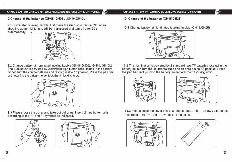
9.1 Illuminated leveling bubble.Just press the illuminous button "N" when shooting at the night, lamp will be illuminated and turn off after 25 s automatically.
9.Change of the batteries (GH08, GH08L ,GH10,GH10L)
9.2 Change battery of illuminated leveling bubble (GH08,GH08L, GH10, GH10L)The illumination is powered by 2 standard type button cells located in the battery holder.Turn the counterbalance and tilt drag dial to "0" position, Press the pan baruntil you find the battery holder,lock the tilt locking knob.
9.3 Please loose the cover and take out old ones. Insert 2 new button cellsaccording to the "+" and "-" symbols as indicated.
10. Change of the batteries (GH15,GH25)
10.1 Change battery of illuminated leveling bubble (GH15,GH25)
10.2 The illumination is powered by 2 standard type 7# batteries located in thebattery holder.Turn the counterbalance and tilt drag dial to "0" position, Pressthe pan bar until you find the battery holder,lock the tilt locking knob.
10.3 Please loose the cover and take out old ones. Insert 2 new 7# batteries
according to the "+" and "-" symbols as indicated.
CHANGE BATTERY OF ILLUMINATED LEVELING BUBBLE (GH15 GH25)CHANGE BATTERY OF ILLUMINATED LEVELING BUBBLE (GH08 GH08L GH10 GH10L)
13 14

G
75mm
75mm
75mm
75mm
AT7402A 650-1510mm 40kg3.3kg695mm
GA751 780-1380mm 820mm 40kg2.9kg
GC751 780-1380mm 820mm 40kg2.6kg
GA752 630-1570mm 720mm 40kg3.5kg
GC752 75mm 630-1570mm 720mm 40kg3.2kg
GA101 100mm 790-1400mm 845mm 60kg4.4kg
GC101 100mm
100mm
100mm
790-1400mm 845mm 60kg3.7kg
GA102 470-1600mm 730mm 60kg4.9kg
GC102 470-1600mm 730mm 60kg4.4kg
E-IMAGE No.
TRIPOD SPECIFICATIONS
Model No. Bowl Size
Descrition Height Range Transport length
Payload rang
Weight
Material
Bowl Size
Section
Two stage Aluminum
Single stage Aluminum
Single stage carbon fiber
Two stage carbon fiber
Two stage Aluminum
Single stage Aluminum
Single stage carbon fiber
Two stage Aluminum
Two stage carbon fiber
EIMAGE GENTING series is upgraded generation of
EIMAGE tripods. The tripod legs are all made up of
high grade aluminum or carbon fiber material. With
newly designed lock system and patent locking
mechanism, it provides excellent hand feeling,
quick and secure locking. With standard 75mm
or 100mm bowl, you can attach any professional
video heads on the tripods. All tripods can match
with mid spreader or ground spreader, just up to
your needs. They also can be installed on dollies
to provide fast moving. The new tripods are compact
when closed, easy to transport with carrying case.
15 16

3. Anti slide rubber feet-
Illustration as follow pictures, pull the pad-removing tab "J", separate anti-sliding pad with leg.
J
I
H
G
DC
B
A
J
Bowl base
Leg tube
Locking knob
Retractable easy hook
Mid spreader
Anti slide rubber pad-
Pad-removing tab
Foot with spike
Loose: turn locking knob "C" anti-clockwise Lock: turn locking knob "C" clockwise
1.Loose lock leg tube &
Important message: before unfold the tripod, please loose all the lockingknobs , then adjust it to your requested length and lock it. "C"
෭
C
lock
loose
PARTS(AT7402A)
Important message: this spike foot is used for out door shooting
2.Adjusting tripod height
Loose all the locking knobs and extend the legs to your request height, then lock knobs tightly.
USE AT7402A
17 18

Bowl base
Leg tube
Patent united lock for two stage lock-
Retractable easy hook
Locking knob of ground speader
Pull ring
Ground spreader
Pad removing tab-
Anti slide rubber pad-
Foot with spike
A
B
CD
E
F
I HG
J
G
D
4. Folding tripod
a: Loose the locking knobs of each stages and adjust the legs to minimumlength, then locking all the knobs.
USE AT7402A PARTS(GA101/GC101)
19 20
b: One hand catch the bowl base, another hand pull the middle spreader "G"and fold it. Then pull out retractable easy hook "D" and wrap around legs and bind them together.

A
B
CD
I
H G
J EF
A
B
C
D
E
F
J
I
H
G
K
Bowl base
Leg tube
Patent united lock for two stage lock-
Retractable easy hook
Locking knob of ground speader
Pull ring
Ground spreader
Pad removing tab-
Anti slide rubber pad-
Foot with spike
PARTS(GA/GC751 GA/GC752)PARTS(GA102/GC102)
21 22

CC
E
F
D
K
J J
lock
loose
1.Loose & lock leg tube
Loose: turn the locking knob "C" anti-clockwiseLock: turn the locking knob "C" clockwise until tight
Important message: Adjust tripod heightLoose all the locking knobs and extend the legs to your request height,then lock knobs tightly.
2.Adjust middle spreader
Loose the locking knob "E" of each arm by turning anti-clockwise, extend the arm to your request length, then re-lock it.
3.Adjust ground spreader
Loose the locking knob "E" of each arm by turning anti-clockwise,extend the arm to your request length, then re-lock it.
4.If you don't need mid-level spreader, pull out the locking bolts "K" of 3 arms and remove it.
5.Install & Remove ground spreader
Illustration as follow pictures,pull the pad-removing tab“J“,separate anti-sliding pad with leg.
6.Folding tripod
a: Loose the locking knobs of each stages and adjust the legs to minium length, then locking all the knobs.b.Adjust the mid-spreader or ground-spreader to minum length,then locking all the knobs.c. One hand catch the bowl base, another hand pull the ring of ground spreader"F"and fold it. Then pull out retractable easy hook "D" and wrap around legs andbind them together.
USE(GA/GC751 GA/GC752 GA/GC101 GA/GC102) USE(GA/GC751 GA/GC752 GA/GC101 GA/GC102)
23 24

Daily maintenance:Storage and transport:
When not using head for a long time, please turn all the knobs
to the minimum.
When not using tripod, please don’t place vertically to avoid
the broken
When not using tripod or transportation, please keep it in the
carry bag.
Function inspection:
Please check the tripod payload and head locking condition,
in order to avoid the accident
Please check and adjust tripod and head locking condition
regularly, in order to increase service life.
Cleaning & Maintenance:
1.Using a regular with a lint free cloth - to clean tripods.2.Please keep it in carrying case if not use it for long time. 3 .Using a semi-stiffe brush or vacuum
Always engage safety locks and devices where applicable on the products.
Don’t use product at temperatures less than -30 or more than 60.
sand from all locking threads and sliding segments.
Dry the product after use in wet conditions.
Cleaning with mild detergent and a soft cloth. Remove dust and
IMPORTANT:Not recommended to use in seawater
If any questions during using process, please read the instructioncarefully or ask help from your local distributor.
In the event on the product becoming defective, the unit should be returned to an authorized E-IMAGE service agent.
Maintenance Notice & Warning
25 26