Embed Size (px)
Citation preview

© Broadband Forum. All rights reserved.
TR-369 User Services Platform (USP) Issue: 1 Amendment 1
ISSUE DATE: October 2019

TR-069 Data Model for Storage Service Enabled Devices TR-140
2
Note: This document provides a PDF formatted version of the specification, which is maintained at http://usp.technology. This is provided for convenience only. The published specification at this URL represents the official normative version. Any discrepancies between this PDF and the specification at usp.technology should refer to the version published at this URL.
User Services Platform (USP) TR-369 Issue 1 Amendment 1
October 2019 © Broadband Forum. All rights reserved 3 of 249
Table of Contents
1 Introduction ................................................................................................................................ 9
1.1 Legal Notice ......................................................................................................................... 9
1.1.1 Intellectual Property ........................................................................................................ 9 1.1.2 Terms of Use ..................................................................................................................... 9
1.2 Revision History ................................................................................................................. 10
1.2.1 Release 1.1 ..................................................................................................................... 10 1.2.2 Release 1.0.2 .................................................................................................................. 10 1.2.3 Release 1.0.1 .................................................................................................................. 10 1.2.4 Release 1.0 ..................................................................................................................... 10
1.3 Editors ................................................................................................................................ 11
1.4 Acknowledgements ............................................................................................................ 11
1.5 Executive Summary ........................................................................................................... 11
1.6 Purpose and Scope ............................................................................................................. 12
1.6.1 Purpose ........................................................................................................................... 12 1.6.2 Scope .............................................................................................................................. 12
1.7 References and Terminology ............................................................................................. 13
1.7.1 Conventions .................................................................................................................... 13 1.7.2 References ...................................................................................................................... 14
2 Definitions ................................................................................................................................. 15
2.1 Abbreviations ..................................................................................................................... 20
3 Specification Impact ................................................................................................................. 21
3.1 Energy efficiency ............................................................................................................... 21
3.2 Security ............................................................................................................................... 21
3.3 Privacy ................................................................................................................................ 22
4 Architecture .............................................................................................................................. 22
4.1 Endpoints ............................................................................................................................ 22
4.1.1 Agents ............................................................................................................................. 24 4.1.2 Controllers ..................................................................................................................... 24 4.1.3 Endpoint Identifier ......................................................................................................... 24
4.2 Service Elements ................................................................................................................ 27
4.2.1 Data Models ................................................................................................................... 27 4.2.2 Path Names .................................................................................................................... 29 4.2.3 Searching ........................................................................................................................ 32 4.2.4 Other Path Decorators ................................................................................................... 34 4.2.5 Data Model Path Grammar ........................................................................................... 37
User Services Platform (USP) TR-369 Issue 1 Amendment 1
October 2019 © Broadband Forum. All rights reserved 4 of 249
5 Discovery and Advertisement .................................................................................................. 45
5.1 Controller Information ....................................................................................................... 46
5.2 Required Agent Information .............................................................................................. 46
5.3 Use of DHCP for Acquiring Controller Information ......................................................... 46
5.3.1 DHCP Options for Controller Discovery ....................................................................... 47 5.4 mDNS ................................................................................................................................. 48
5.5 DNS .................................................................................................................................... 48
5.5.1 DNS-SD Records ............................................................................................................ 48 5.5.2 IANA-Registered USP Service Names ............................................................................ 49 5.5.3 Example Controller Unicast DNS-SD Resource Records .............................................. 50 5.5.4 Example Agent Multicast DNS-SD Resource Records ................................................... 50 5.5.5 Example Controller Multicast DNS-SD Resource Records ........................................... 50
5.6 Using the SendOnBoardRequest() operation and OnBoardRequest notification .............. 51
6 Message Transfer Protocols .................................................................................................... 51
6.1 Supporting Multiple MTPs ................................................................................................. 51
6.2 Securing MTPs ................................................................................................................... 51
6.3 Brokered USP Record Errors ............................................................................................. 54
7 CoAP Binding ........................................................................................................................... 54
7.1 Mapping USP Endpoints to CoAP URIs ............................................................................ 55
7.2 Mapping USP Records to CoAP Messages ........................................................................ 56
7.2.1 Handling CoAP Request Success ................................................................................... 56 7.2.2 Handling CoAP Request Failures .................................................................................. 56
7.3 MTP Message Encryption .................................................................................................. 57
8 STOMP Binding ....................................................................................................................... 58
8.1 Handling of the STOMP Session ....................................................................................... 59
8.1.1 Connecting a USP Endpoint to the STOMP Server ....................................................... 60 8.1.2 Handling the STOMP Heart Beat Mechanism ............................................................... 60
8.2 Mapping USP Endpoints to STOMP Destinations ............................................................ 61
8.2.1 Subscribing a USP Endpoint to a STOMP Destination ................................................. 61 8.3 Mapping USP Records to STOMP Frames ........................................................................ 62
8.3.1 Handling USP Record errors and ERROR Frames ....................................................... 63 8.3.2 Handling Other STOMP Frames ................................................................................... 64
8.4 Discovery Requirements .................................................................................................... 64
8.5 STOMP Server Requirements ............................................................................................ 65
8.6 MTP Message Encryption .................................................................................................. 65
User Services Platform (USP) TR-369 Issue 1 Amendment 1
October 2019 © Broadband Forum. All rights reserved 5 of 249
9 WebSocket Binding .................................................................................................................. 65
9.1 Mapping USP Endpoints to WebSocket URIs ................................................................... 65
9.2 Handling of the WebSocket Session .................................................................................. 66
9.2.1 Mapping USP Records to WebSocket Messages ............................................................ 67 9.3 Handling of WebSocket Frames ........................................................................................ 68
9.3.1 Handling Failures to Deliver USP Records ................................................................... 69 9.3.2 Keeping the WebSocket Session Alive ............................................................................ 69 9.3.3 WebSocket Session Retry ................................................................................................ 69
9.4 MTP Message Encryption .................................................................................................. 71
10 MQTT Binding ......................................................................................................................... 71
10.1 Connecting a USP Endpoint to the MQTT Server ............................................................. 74
10.1.1 CONNECT Flags and Properties ............................................................................... 75 10.1.2 Keep Alive .................................................................................................................. 76
10.2 Subscribing to MQTT Topics ............................................................................................ 76
10.3 Sending the USP Record in a PUBLISH Packet Payload .................................................. 78
10.4 Handling Errors .................................................................................................................. 79
10.5 Handling Other MQTT Packets ......................................................................................... 80
10.6 Discovery Requirements .................................................................................................... 81
10.7 MQTT Server Requirements .............................................................................................. 81
10.8 MTP Message Encryption .................................................................................................. 82
11 Message Encoding .................................................................................................................... 82
12 End to End Message Exchange ............................................................................................... 83
12.1 USP Record Encapsulation ................................................................................................ 84
12.1.1 Record Definition ....................................................................................................... 84 12.2 Exchange of USP Records within an E2E Session Context ............................................... 87
12.2.1 Establishing an E2E Session Context ......................................................................... 87 12.2.2 USP Record Exchange ............................................................................................... 90 12.2.3 Guidelines for Handling Session Context Restarts .................................................... 93 12.2.4 Segmented Message Exchange ................................................................................... 94 12.2.5 Handling Duplicate USP Records ............................................................................ 102
12.3 Exchange of USP Records without an E2E Session Context ........................................... 102
12.3.1 Failure Handling of Received USP Records Without a Session Context ................. 102 12.4 Validating the Integrity of the USP Record ..................................................................... 102
12.4.1 Using the Signature Method to Validate the Integrity of USP Records ................... 103 12.4.2 Using TLS to Validate the Integrity of USP Records ............................................... 104
12.5 Secure Message Exchange ............................................................................................... 105
User Services Platform (USP) TR-369 Issue 1 Amendment 1
October 2019 © Broadband Forum. All rights reserved 6 of 249
12.5.1 TLS Payload Encapsulation ..................................................................................... 105
13 Messages .................................................................................................................................. 108
13.1 Encapsulation in a USP Record ....................................................................................... 108
13.2 Requests, Responses and Errors ....................................................................................... 108
13.2.1 Handling Duplicate Messages ................................................................................. 109 13.2.2 Example Message Flows .......................................................................................... 109
13.3 Message Structure ............................................................................................................ 111
13.3.1 The USP Message ..................................................................................................... 112 13.3.2 Message Header ....................................................................................................... 112 13.3.3 Message Body ........................................................................................................... 113
13.4 Creating, Updating, and Deleting Objects ....................................................................... 115
13.4.1 Selecting Objects and Parameters ........................................................................... 115 13.4.2 Using Allow Partial and Required Parameters ....................................................... 116 13.4.3 The Add Message ..................................................................................................... 117 13.4.4 The Set Message ....................................................................................................... 121 13.4.5 The Delete Message ................................................................................................. 126
13.5 Reading an Agent’s State and Capabilities ...................................................................... 130
13.5.1 The Get Message ...................................................................................................... 130 13.5.2 The GetInstances Message ....................................................................................... 137 13.5.3 The GetSupportedDM Message ............................................................................... 141 13.5.4 GetSupportedProtocol .............................................................................................. 147
13.6 Notifications and Subscription Mechanism ..................................................................... 147
13.6.1 Using Subscription Objects ...................................................................................... 148 13.6.2 Responses to Notifications and Notification Retry ................................................... 148 13.6.3 Notification Types .................................................................................................... 150 13.6.4 The Notify Message .................................................................................................. 153
13.7 Defined Operations Mechanism ....................................................................................... 156
13.7.1 Synchronous Operations .......................................................................................... 156 13.7.2 Asynchronous Operations ........................................................................................ 157 13.7.3 Operate Requests on Multiple Objects ..................................................................... 158 13.7.4 Event Notifications for Operations .......................................................................... 159 13.7.5 Concurrent Operations ............................................................................................ 159 13.7.6 Operate Examples .................................................................................................... 159 13.7.7 The Operate Message ............................................................................................... 160
13.8 Error Codes ...................................................................................................................... 162
13.8.1 Vendor Defined Error Codes ................................................................................... 164
14 Authentication and Authorization ........................................................................................ 164
14.1 Authentication .................................................................................................................. 165
14.2 Role Based Access Control (RBAC) ............................................................................... 165
14.3 Trusted Certificate Authorities ......................................................................................... 166
User Services Platform (USP) TR-369 Issue 1 Amendment 1
October 2019 © Broadband Forum. All rights reserved 7 of 249
14.4 Trusted Brokers ................................................................................................................ 167
14.5 Self-Signed Certificates .................................................................................................... 167
14.6 Agent Authentication ....................................................................................................... 168
14.7 Challenge Strings and Images .......................................................................................... 169
14.8 Analysis of Controller Certificates ................................................................................... 170
14.8.1 Receiving a USP Record .......................................................................................... 170 14.8.2 Sending a USP Record ............................................................................................. 173 14.8.3 Checking a Certificate Containing an Endpoint ID ................................................. 175 14.8.4 Using a Trusted Broker ............................................................................................ 176
14.9 Theory of Operations ....................................................................................................... 178
14.9.1 Data Model Elements ............................................................................................... 179 14.9.2 Roles (Access Control) ............................................................................................. 179 14.9.3 Assigning Controller Roles ...................................................................................... 182 14.9.4 Controller Certificates and Certificate Validation .................................................. 183 14.9.5 Challenges ................................................................................................................ 183 14.9.6 Certificate Management ........................................................................................... 184 14.9.7 Application of Modified Parameters ........................................................................ 184
15 Annex A - HTTP Bulk Data Collection ................................................................................ 185
15.1 Enabling HTTP/HTTPS Bulk Data Communication ....................................................... 185
15.1.1 Use of the URI Query Parameters ........................................................................... 186 15.1.2 Use of HTTP Status Codes ....................................................................................... 187 15.1.3 Use of TLS and TCP ................................................................................................. 188
15.2 Encoding of Bulk Data ..................................................................................................... 190
15.2.1 Using Wildcards to Reference Object Instances in the Report ................................ 190 15.2.2 Using Alternative Names in the Report .................................................................... 191 15.2.3 Processing of Content for Failed Report Transmissions ......................................... 193 15.2.4 Encoding of CSV Bulk Data ..................................................................................... 193 15.2.5 Encoding of JSON Bulk Data ................................................................................... 196
16 Appendix I - Software Module Management ....................................................................... 200
16.1 Lifecycle Management ..................................................................................................... 201
16.2 Software Modules ............................................................................................................ 201
16.2.1 Deployment Units ..................................................................................................... 202 16.2.2 Execution Units ........................................................................................................ 206
16.3 Execution Environment Concepts .................................................................................... 209
16.4 Fault Model ...................................................................................................................... 211
16.4.1 DU Faults ................................................................................................................. 211 16.4.2 EU Faults ................................................................................................................. 214
17 Appendix I - Firmware Management of Devices with USP Agents ................................... 215
17.1 Getting the firmware image onto the device .................................................................... 216
User Services Platform (USP) TR-369 Issue 1 Amendment 1
October 2019 © Broadband Forum. All rights reserved 8 of 249
17.2 Using multiple firmware images ...................................................................................... 216
17.2.1 Switching firmware images ...................................................................................... 217 17.2.2 Performing a delayed firmware upgrade ................................................................. 217 17.2.3 Recovering from a failed upgrade ............................................................................ 217
18 Appendix III - Device Proxy .................................................................................................. 218
19 Appendix IV - Proxying ......................................................................................................... 218
19.1 Proxying Building Block Functions ................................................................................. 219
19.2 Discovery Proxy ............................................................................................................... 220
19.3 Connectivity Proxy ........................................................................................................... 220
19.4 Message Transfer Protocol (MTP) Proxy ........................................................................ 221
19.4.1 MTP Header Translation Algorithms ...................................................................... 221 19.4.2 CoAP / STOMP MTP Proxy Example Message Flow .............................................. 225
19.5 USP to Non-USP Proxy ................................................................................................... 228
20 Appendix V - IoT Data Model Theory of Operation .......................................................... 228
20.1 Introduction ...................................................................................................................... 228
20.2 IoT data model overview .................................................................................................. 228
20.2.1 IoT Capability table ................................................................................................. 229 20.2.2 Node object table ...................................................................................................... 230
20.3 Architecture mappings ..................................................................................................... 230
20.3.1 Individual IoT devices .............................................................................................. 230 20.3.2 Proxied IoT devices .................................................................................................. 231
20.4 IoT data model object details ........................................................................................... 231
20.4.1 Common capability parameters ............................................................................... 231 20.4.2 Control Objects ........................................................................................................ 232 20.4.3 Sensor Objects .......................................................................................................... 234
20.5 Examples .......................................................................................................................... 239
20.5.1 Example: A/C Thermostat ........................................................................................ 240 20.5.2 Example: Light with a dimmer and switch ............................................................... 242 20.5.3 Example: Fan ........................................................................................................... 242 20.5.4 Example: Multi-Sensor strip with a common battery. .............................................. 243 20.5.5 Example: Ceiling Fan with integrated light ............................................................. 243 20.5.6 Example: Power strip ............................................................................................... 245 20.5.7 Example: Battery powered radiator thermostat ....................................................... 247
User Services Platform (USP) TR-369 Issue 1 Amendment 1
October 2019 © Broadband Forum. All rights reserved 9 of 249
1 Introduction
1.1 Legal Notice
The Broadband Forum is a non-profit corporation organized to create guidelines for broadband network system development and deployment. This Technical Report has been approved by members of the Forum. This Technical Report is subject to change. This Technical Report is copyrighted by the Broadband Forum, and all rights are reserved. Portions of this Technical Report may be copyrighted by Broadband Forum members.
1.1.1 Intellectual Property
Recipients of this Technical Report are requested to submit, with their comments, notification of any relevant patent claims or other intellectual property rights of which they may be aware that might be infringed by any implementation of this Technical Report, or use of any software code normatively referenced in this Technical Report, and to provide supporting documentation.
1.1.2 Terms of Use
1.1.2.1 License
Broadband Forum hereby grants you the right, without charge, on a perpetual, non-exclusive and worldwide basis, to utilize the Technical Report for the purpose of developing, making, having made, using, marketing, importing, offering to sell or license, and selling or licensing, and to otherwise distribute, products complying with the Technical Report, in all cases subject to the conditions set forth in this notice and any relevant patent and other intellectual property rights of third parties (which may include members of Broadband Forum). This license grant does not include the right to sublicense, modify or create derivative works based upon the Technical Report except to the extent this Technical Report includes text implementable in computer code, in which case your right under this License to create and modify derivative works is limited to modifying and creating derivative works of such code. For the avoidance of doubt, except as qualified by the preceding sentence, products implementing this Technical Report are not deemed to be derivative works of the Technical Report.
1.1.2.2 NO WARRANTIES
THIS TECHNICAL REPORT IS BEING OFFERED WITHOUT ANY WARRANTY WHATSOEVER, AND IN PARTICULAR, ANY WARRANTY OF NONINFRINGEMENT IS EXPRESSLY DISCLAIMED. ANY USE OF THIS TECHNICAL REPORT SHALL BE MADE ENTIRELY AT THE IMPLEMENTER’S OWN RISK, AND NEITHER THE BROADBAND FORUM, NOR ANY OF ITS MEMBERS OR SUBMITTERS, SHALL HAVE ANY LIABILITY WHATSOEVER TO ANY IMPLEMENTER OR THIRD PARTY FOR ANY DAMAGES OF

User Services Platform (USP) TR-369 Issue 1 Amendment 1
October 2019 © Broadband Forum. All rights reserved 10 of 249
ANY NATURE WHATSOEVER, DIRECTLY OR INDIRECTLY, ARISING FROM THE USE OF THIS TECHNICAL REPORT.
1.1.2.3 THIRD PARTY RIGHTS
Without limiting the generality of Section 2 above, BROADBAND FORUM ASSUMES NO RESPONSIBILITY TO COMPILE, CONFIRM, UPDATE OR MAKE PUBLIC ANY THIRD PARTY ASSERTIONS OF PATENT OR OTHER INTELLECTUAL PROPERTY RIGHTS THAT MIGHT NOW OR IN THE FUTURE BE INFRINGED BY AN IMPLEMENTATION OF THE TECHNICAL REPORT IN ITS CURRENT, OR IN ANY FUTURE FORM. IF ANY SUCH RIGHTS ARE DESCRIBED ON THE TECHNICAL REPORT, BROADBAND FORUM TAKES NO POSITION AS TO THE VALIDITY OR INVALIDITY OF SUCH ASSERTIONS, OR THAT ALL SUCH ASSERTIONS THAT HAVE OR MAY BE MADE ARE SO LISTED.
The text of this notice must be included in all copies of this Technical Report.
1.2 Revision History
1.2.1 Release 1.1
• Release contains specification for the User Services Platform 1.1.
– Adds MQTT support as a Message Transfer Protocol
– Adds a theory of operations for IoT control using USP Agents
– Clarifications on protocol functions, error messages, and updates to examples
Valid versions for USP Agents as of this release include “1.1” and “1.0”.
1.2.2 Release 1.0.2
• Typographical and example fixes
1.2.3 Release 1.0.1
• Added examples and clarifications to end-to-end messaging, use of endpoint ID, typographical fixes
1.2.4 Release 1.0
• Release contains specification for the User Services Platform 1.0.
User Services Platform (USP) TR-369 Issue 1 Amendment 1
October 2019 © Broadband Forum. All rights reserved 11 of 249
1.3 Editors
• Name • Company • Email • Role • Barbara
Stark • AT&T • [email protected] • Editor/USP Project
Lead • Tim
Spets • Green
Wave Systems
• [email protected] • Editor/USP Project Lead
• Jason Walls
• QA Cafe, LLC
• [email protected] • Editor/Broadband User Services Work Area Director
• John Blackford
• Arris • [email protected] • Editor/Broadband User Services Work Area Director
1.4 Acknowledgements
The following individuals are being acknowledged for their efforts in the testing and development of this specification.
• Name • Company • Email • Jean-Didier Ott • Orange • [email protected] • Timothy Carey • Nokia • [email protected] • Steven Nicolai • Arris • [email protected] • Apostolos Papageorgiou • NEC • [email protected] • Mark Tabry • Google • [email protected] • Klaus Wich • Huawei • [email protected] • Daniel Egger • Axiros • [email protected] • Bahadir Danisik • Nokia • [email protected]
1.5 Executive Summary
This document describes the architecture, protocol, and data model that builds an intelligent User Services Platform. It is targeted towards application developers, application service providers, CPE vendors, consumer electronics manufacturers, and broadband and mobile network providers who want to expand the value of the end user’s network connection and their connected devices.
The term “connected device” is a broad one, applying to the vast array of network connected CPE, consumer electronics, and computing resources that today’s consumers are using at an increasing rate. With the advent of “smart” platforms (phones, tablets, and wearables) plus the emerging

User Services Platform (USP) TR-369 Issue 1 Amendment 1
October 2019 © Broadband Forum. All rights reserved 12 of 249
Internet of Things, the number of connected devices the average user or household contains is growing by several orders of magnitude.
In addition, users of the fixed and mobile broadband network are hungry for advanced broadband and intelligent cloud services. As this desire increases, users are turning towards over-the-top providers to consume the entertainment, productivity, and storage applications they want.
These realities have created an opportunity for consumer electronics vendors, application developers, and broadband and mobile network providers. These connected devices and services need to be managed, monitored, troubleshot, and controlled in an easy to develop and interoperable way. A unified framework for these is attractive if we want to enable providers, developers, and vendors to create value for the end user. The goal should be to create system for developing, deploying, and supporting these services for end users on the platform created by their connectivity and components, that is, to be able to treat the connected user herself as a platform for applications.
To address this opportunity, use cases supported by USP include:
• Management of IoT devices through re-usable data model objects.
• Allowing the user to interact with their devices and services using customer portals or control points on their own smart devices.
• The ability to have both the application and network service provider manage, troubleshoot, and control different aspects of the services they are responsible for, and enabling provider partnerships.
• Providing a consistent user experience from mobile to home.
• Simple migration from the CPE WAN Management Protocol (CWMP) - commonly known by its document number, “TR-069” - through use of the same data model and data modeling tools.
1.6 Purpose and Scope
1.6.1 Purpose
This document provides the normative requirements and operational description of the User Services Platform (USP). USP is designed for consumer electronics/IoT, home network/gateways, smart WiFi systems, and virtual services (though could theoretically be used for any connected device in many different verticals). It is targeted towards developers, application providers, and network service providers looking to deploy those products.
1.6.2 Scope
This document identifies the USP:
• Architecture

User Services Platform (USP) TR-369 Issue 1 Amendment 1
October 2019 © Broadband Forum. All rights reserved 13 of 249
• Record structure, syntax, and rules
• Message structure, syntax, and rules
• Bindings that allow specific protocols to carry USP Records in their payloads
• Discovery and advertisement mechanisms
• Security credentials and logic
• Encryption mechanisms
Lastly, USP makes use of and expands the Device:2 Data Model. While particular Objects and parameters necessary to the function of USP are mentioned here, their normative description can be found in that XML document.
1.7 References and Terminology
1.7.1 Conventions
In this specification, several words are used to signify the requirements of the specification. These words are always capitalized. More information can be found be in RFC 2119.
MUST
This word, or the term “REQUIRED”, means that the definition is an absolute requirement of the specification.
MUST NOT
This phrase means that the definition is an absolute prohibition of the specification.
SHOULD
This word, or the term “RECOMMENDED”, means that there could exist valid reasons in particular circumstances to ignore this item, but the full implications need to be understood and carefully weighed before choosing a different course.
SHOULD NOT
This phrase, or the phrase “NOT RECOMMENDED” means that there could exist valid reasons in particular circumstances when the particular behavior is acceptable or even useful, but the full implications need to be understood and the case carefully weighed before implementing any behavior described with this label.
MAY
User Services Platform (USP) TR-369 Issue 1 Amendment 1
October 2019 © Broadband Forum. All rights reserved 14 of 249
This word, or the term “OPTIONAL”, means that this item is one of an allowed set of alternatives. An implementation that does not include this option MUST be prepared to inter-operate with another implementation that does include the option.
1.7.2 References
The following references are of relevance to this Technical Report. At the time of publication, the editions indicated were valid. All references are subject to revision; users of this Technical Report are therefore encouraged to investigate the possibility of applying the most recent edition of the references listed below.
A list of currently valid Broadband Forum Technical Reports is published at www.broadband-forum.org.
1. Broadband Forum TR-181 Issue 2: Device Data Model
2. Broadband Forum TR-069 Amendment 6: CPE WAN Management Protocol
3. Broadband Forum TR-106 Amendment 8: Data Model Template for CWMP Endpoints and USP Agents
4. IETF RFC 7228: Terminology for Constrained-Node Networks
5. IETF RFC 2136: Dynamic Updates in the Domain Name System
6. IETF RFC 3007: Secure Domain Name System Dynamic Update
7. IETF RFC 6763: DNS-Based Service Discovery
8. IETF RFC 6762: Multicast DNS
9. IETF RFC 7252: The Constrained Application Protocol (CoAP)
10. IETF RFC 7390: Group Communication for the Constrained Application Protocol (CoAP)
11. IETF RFC 4033: DNS Security Introduction and Requirements
12. Protocol Buffers v3 Protocol Buffers Mechanism for Serializing Structured Data Version 3
13. IEEE Registration Authority
14. IETF RFC 4122 A Universally Unique IDentifier (UUID) URN Namespace
15. IETF RFC 5290: Internet X.509 Public Key Infrastructure Certificate and Certificate Revocation List (CRL) Profile
16. IETF RFC 6818: Updates to the Internet X.509 Public Key Infrastructure Certificate and Certificate Revocation List (CRL) Profile
17. IETF RFC 2234 Augmented BNF for Syntax Specifications: ABNF
User Services Platform (USP) TR-369 Issue 1 Amendment 1
October 2019 © Broadband Forum. All rights reserved 15 of 249
18. IETF RFC 3986 Uniform Resource Identifier (URI): Generic Syntax
19. IETF RFC 2141 URN Syntax
20. IETF RFC 6455 The WebSocket Protocol
21. Simple Text Oriented Message Protocol
22. The Transport Layer Security (TLS) Protocol Version 1.2
23. Datagram Transport Layer Security Version 1.2
24. MQ Telemetry Transport 5.024.
2 Definitions The following terminology is used throughout this specification.
Agent
An Agent is an Endpoint that exposes Service Elements to one or more Controllers.
Binding
A Binding is a means of sending Messages across an underlying Message Transfer Protocol.
Command
The term used to define and refer to an Object-specific Operation in the Agent’s Instantiated or Supported Data Model.
Connection Capabilities
Connection Capabilities are information related to an Endpoint that describe how to communicate with that Endpoint, and provide a very basic idea of what sort of function the Endpoint serves.
User Services Platform
The User Services Platform consists of a data model, architecture, and communications protocol to transform consumer broadband networks into a platform for the development, deployment, and support of broadband enabled applications and services.
Controller
A Controller is an Endpoint that manipulates Service Elements through one or more Agents.
Device Type (DT) Definition
A Device Type Definition (DT) is a description of the Service Elements an Agent is able to support, defining its Supported Data Model.
User Services Platform (USP) TR-369 Issue 1 Amendment 1
October 2019 © Broadband Forum. All rights reserved 16 of 249
Discovery
Discovery is the process by which Controllers become aware of Agents and Agents become aware of Controllers.
Endpoint
An Endpoint is a termination point for a Message.
Endpoint Identifier
The Endpoint Identifier is a globally unique USP layer identifier of an Endpoint.
End to End Message Exchange
USP feature that allows for message integrity protection through the creation of a session context.
Error
An Error is a Message that contains failure information associated with a Request.
Event
An Event is a set of conditions that, when met, triggers the sending of a Notification.
Expression
See also Search Expression
Expression Component
An Expression Component is the part of a Search Expression that gives the matching Parameter criteria for the search. It is comprised of an Expression Parameter followed by an Expression Operator followed by an Expression Constant.
Expression Constant
The Expression Constant is the value used to compare against the Expression Component to determine if a search matches a given Object.
Expression Operator
The Expression Operator is the operator used to determine how the Expression Component will be evaluated against the Expression Constant, i.e., equals (==), not equals (!=), less than (<), greater than (>), less than or equal (<=), and greater than or equal (>=).
Expression Parameter

User Services Platform (USP) TR-369 Issue 1 Amendment 1
October 2019 © Broadband Forum. All rights reserved 17 of 249
The Expression Parameter is a Parameter relative to the path where an Expression Variable occurs that will be used with the Expression Constant to evaluate the Expression Component.
Expression Variable
The Expression Variable is an identifier used to allow relative addressing when building an Expression Component.
Instantiated Data Model
The Instantiated Data Model of an Agent represents the current set of Service Elements (and their state) that are exposed to one or more Controllers.
Instance Identifier
A term used to identify to an Instance of a Multi-Instance Object (also called a Row of a Table). While all Multi-Instance Objects have an Instance Number that can be used as an Instance Identifier, an Object Instance can also be referenced using that Object’s Unique Key.
Instance Number
An Instance Number is a numeric Instance Identifier assigned by the Agent to instances of Multi-Instance Objects in an Agent’s Instantiated Data Model.
Instance Path
An Instance Path is a Path Name that addresses an Instance of a Multi-Instance Object (also called a Row of a Table). It includes the Object Path followed by an Instance Identifier.
Message
A Message refers to the contents of a USP layer communication including exactly one Message Header and at most one Message Body.
Message Body
The Message Body is the portion of a Message that contains one of the following: Request, Response, or Error.
Message Header
The portion of a Message that contains elements that provide information about the message, including the Endpoint Identifier of the sender and receiver, message type, and Message ID elements.
Message ID
A Message ID is an identifier used to associate a Response or Error with a Request.

User Services Platform (USP) TR-369 Issue 1 Amendment 1
October 2019 © Broadband Forum. All rights reserved 18 of 249
Message Transfer Protocol
A Message Transfer Protocol (MTP) is the protocol at a layer below USP that carries a Message, i.e., CoAP.
Multi-Instance Object
A Multi-Instance Object refers to an Object that can be created or deleted in the Agent’s Instantiated Data Model. Also called a Table.
Notification
A Notification is a Request from an Agent that conveys information about an Event to a Controller that has a Subscription to that event.
Object
An Object refers to a defined type that an Agent represents and exposes. A Service Element may be comprised of one or more Objects and Sub-Objects.
Object Instance
An Object Instance refers to a single instance Object of a type defined by a Multi-Instance Object in the Agent’s Instantiated Data Model. Also called a Row of a Table.
Object Path
An Object Path is a Path Name that addresses an Object. In the case of Multi-Instance Objects, an Object Path addresses the Object type itself rather than instances of that Object, which are addressed by Instance Paths
Operation
A method defined for a particular Service Element that can be invoked with the Operate message.
Parameter
A Parameter is a variable or attribute of an Object. Parameters have both type and value.
Parameter Path
A Parameter Path is a Path Name that addresses a Parameter of an Object or Object Instance.
Path Name
A Path Name is a fully qualified reference to an Object, Object Instance, or Parameter in an Agent’s instantiated or Supported Data Model.
Path Reference

User Services Platform (USP) TR-369 Issue 1 Amendment 1
October 2019 © Broadband Forum. All rights reserved 19 of 249
A Path Reference is a Parameter data type that contains a Path Name to an Object or Parameter that may be automatically followed by using certain Path Name syntax.
Record
The Record is defined as the Message Transfer Protocol (MTP) payload, encapsulating a sequence of datagrams that comprise the Message as well as providing additional metadata needed for providing integrity protection, payload protection and delivery of fragmented Messages.
Relative Path
A Relative Path is the remaining path information necessary to form a Path Name given a parent Object Path. It is used for message efficiency when addressing Path Names.
Request
A Request is a type of Message that either requests the Agent perform some action (create, update, delete, operate, etc.), requests information about an Agent or one or more Service Elements, or acts as a means to deliver Notifications from the Agent to the Controller. A Request usually requires a Response.
Response
A Response is a type of Message that provides return information about the successful processing of a Request.
Row
The term Row refers to an Instance of a Multi-Instance Object in the Agent’s Instantiated Data Model.
Search Expression
A Search Expression is used in a Search Path to apply specified search criteria to address a set of Multi-Instance Objects and/or their Parameters.
Search Path
A Search Path is a Path Name that contains search criteria for addressing a set of Multi-Instance Objects and/or their Parameters. A Search Path may contain a Search Expression or Wildcard.
Service Element
A Service Element represents a piece of service functionality that is exposed by an Agent, usually represented by one or more Objects.
Source Endpoint
An Endpoint that was the sender of a message.
User Services Platform (USP) TR-369 Issue 1 Amendment 1
October 2019 © Broadband Forum. All rights reserved 20 of 249
Subscription
A Subscription is a set of logic that tells an Agent which Notifications to send to a particular Controller.
Supported Data Model
The Supported Data Model of an Agent represents the complete set of Service Elements it is capable of exposing to a Controller. It is defined by the union of all of the Device Type Definitions the Agent exposes to the Controller.
Table
The term Table refers to a Multi-Instance Object in an Agent’s Instantiated or Supported Data Model.
Target Endpoint
An Endpoint that was the intended receiver of a message.
Trusted Broker
An intermediary that either (1) ensures the Endpoint ID in all brokered Endpoint’s USP Record from_id matches the Endpoint ID of those Endpoint’s certificates or credentials, before sending on a USP Record to another Endpoint, or (2) is part of a closed ecosystem that “knows” (certain) Endpoints can be trusted not to spoof the Endpoint ID.
Unique Key
The Unique Key of a Multi-Instance Object is a set of Parameters that uniquely identify the instance of an Object in the Agent’s Instantiated Data Model and can be used as an Instance Identifier.
Wildcard
A Wildcard is used in a Search Path to address all Object Instances of a Multi-Instance Object.
2.1 Abbreviations
This specification uses the following abbreviations:
• abbreviation • term • ABNF • Augmented Backus-Naur Form • CoAP • Constrained Application Protocol • USP • User Services Platform • CWMP • CPE WAN Management Protocol • DNS • Domain Name Service
User Services Platform (USP) TR-369 Issue 1 Amendment 1
October 2019 © Broadband Forum. All rights reserved 21 of 249
• DNS-SD • Domain Name Service - Service Definition • DT • Device Type Definition • E2E • End to End (Message Exchange) • HMAC • Hash Message Authentication Code • HTTP • Hypertext Transport Protocol • mDNS • Multicast Domain Name Service • IPv4/v6 • Internet Protocol (version 4 or version 6) • LAN • Local Area Network • MAC • Message Authentication Code • MTP • Message Transfer Protocol • OUI • Organizationally Unique Identifier • PSS • Probabilistic Signature Scheme • SAR • Segmentation And Reassembly • SMM • Software Module Management • TLS • Tranport Layer Security • TR • Technical Report • URI • Uniform Resource Identifier • URL • Uniform Resource Locator • UUID • Universally Unique Identifier • WAN • Wide Area Network
3 Specification Impact
3.1 Energy efficiency
The User Services Platform reaches into more and newer connected devices, and expands on the management of physical hardware, including power management. In addition, USP directly enables smart home, smart building, and other smart energy applications.
3.2 Security
Any solution that provides a mechanism to manage, monitor, diagnose, and control a connected user’s network, devices, and applications must prioritize security to protect user data and prevent malicious use of the system. This is especially important with certain high-risk smart applications like medicine or emergency services.
However reliable the security of communications protocols, in a platform that enables interoperable components that may or may not be connected with protocols outside the scope of the specification, security must be considered from end-to-end. To realize this, USP contains its own security mechanisms.

User Services Platform (USP) TR-369 Issue 1 Amendment 1
October 2019 © Broadband Forum. All rights reserved 22 of 249
3.3 Privacy
Privacy is the right of an individual or group to control or influence what information related to them may be collected, processed, and stored and by whom, and to whom that information may be disclosed.
Assurance of privacy depends on whether stakeholders expect, or are legally required, to have information protected or controlled from certain uses. As with security, the ability for users to control who has access to their data is of primary importance in the world of the connected user, made clear by users as well as regulators.
USP contains rigorous access control and authorization mechanisms to ensure that data is only used by those that have been enabled by the user.
4 Architecture The User Services Platform consists of a collection of Endpoints (Agents and Controllers) that allow applications to manipulate Service Elements. These Service Elements are made up of a set of Objects and parameters that model a given service, such as network interfaces, software modules, device firmware, remote elements proxied through another interface, virtual elements, or other managed services.
USP is made up of several architectural components:
• Mechanisms for discovery and trust establishment
• A method for encoding messages for transport
• A system for end-to-end confidentiality, integrity and identity authentication
• Transport of messages over one or more Message Transfer Protocols (MTPs) with associated MTP security
• A set of standardized messages based on the CRUD model (create, read, update, delete), plus an object defined operations mechanism and an notification mechanism (CRUD-ON)
• Authorization and access control on a per element basis
• A method for modeling service elements using a set of objects, parameters, operations, and events (supported and instantiated data models)
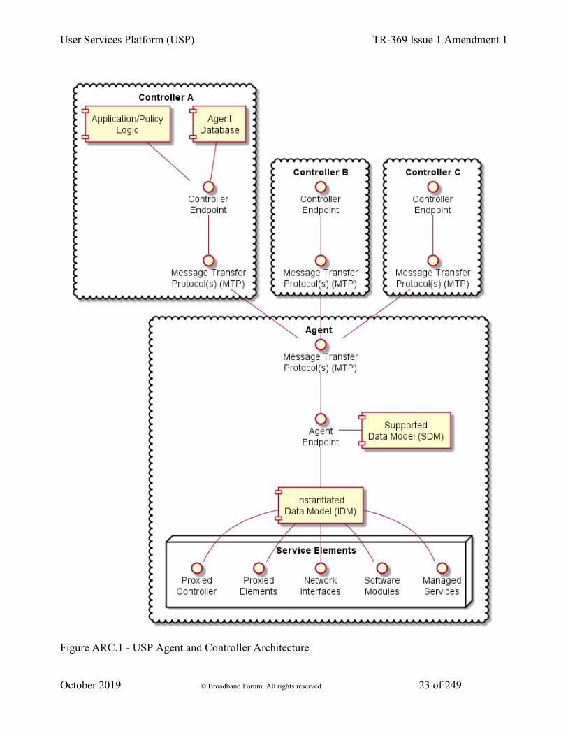
4.1 Endpoints
A USP endpoint can act as Agent or a Controller. Controllers only send messages to Agents, and Agents send messages to Controllers. A USP Endpoint communicates over a secure session between other endpoints, over one or more Message Transfer Protocols (MTP) that may or may not be secured.
User Services Platform (USP) TR-369 Issue 1 Amendment 1
October 2019 © Broadband Forum. All rights reserved 23 of 249
Figure ARC.1 - USP Agent and Controller Architecture
User Services Platform (USP) TR-369 Issue 1 Amendment 1
October 2019 © Broadband Forum. All rights reserved 24 of 249
4.1.1 Agents
A USP Agent exposes (to Controllers) one or more Service Elements that are represented in its data model. It contains or references both an Instantiated Data Model (representing the current state of Service Elements it represents) and a Supported Data Model.
4.1.2 Controllers
A USP Controller manipulates (through Agents) a set of Service Elements that are represented in Agent data models. It may maintain a database of Agents, their capabilities, and their states, in any combination. A Controller usually acts as an interface to a user application or policy engine that uses the User Services Platform to address particular use cases.
4.1.3 Endpoint Identifier
Endpoints are identified by an Endpoint Identifier.
The Endpoint Identifier is a locally or globally unique USP layer identifier of an Endpoint. Whether it is globally or locally unique depends on the scheme used for assignment.
The Endpoint Identifier (ID) is used in the USP Record and various Parameters in a USP Message to uniquely identify Controller and Agent Endpoints. It can be globally or locally unique, either among all Endpoints or among all Controllers or all Agents, depending on the scheme used for assignment.
The Endpoint ID is comprised of two mandatory and one optionally mandatory components: authority-scheme, authority-id, and instance-id.
These three components are combined as:
authority-scheme ":" [authority-id] ":" instance-id
The format of the authority-id is dictated by the authority-scheme. The format of the instance-id is dictated either by the authority-scheme or by the entity identified by the authority-id.
When used in a certificate, an Endpoint ID is expressed as a urn in the bbf namespace as:
"urn:bbf:usp:id:" authority-scheme ":" [authority-id] ":" instance-id
When used anywhere else (e.g. in the to_id and from_id of a USP Record), the namespace information is omitted, and the Endpoint ID is expressed as:
authority-scheme ":" [authority-id] ":" instance-id

User Services Platform (USP) TR-369 Issue 1 Amendment 1
October 2019 © Broadband Forum. All rights reserved 25 of 249
4.1.3.1 Use of authority-scheme and authority-id
The authority-scheme follows the following syntax:
authority-scheme = "oui" | "cid" | "pen" | "self" | "user" | "os" | "ops" | "uuid" | "imei" | "proto" | "doc"
How these authority-scheme values impact the format and values of authority-id and instance-id is described below.
The authority defined by an OUI, CID, or Private Enterprise Number (including OUI used in “ops” and “os” authority scheme) is responsible for ensuring the uniqueness of the resulting Endpoint ID. Uniqueness can be global, local, unique across all Endpoints, or unique among all Controllers or all Agents. For the “user” authority scheme, the assigning user or machine is responsible for ensuring uniqueness. For the “self” authority scheme, the Endpoint is responsible for ensuring uniqueness.
R-ARC.0 - A Controller and Agent within the same ecosystem MAY use the same Endpoint ID.
R-ARC.1 - Endpoints MUST tolerate the same Endpoint ID being used by an Agent and a Controller in the same ecosystem.
R-ARC.2 - Endpoints that share the same Endpoint ID MUST NOT communicate with each other via USP.
No conflict identification or resolution process is defined in USP to deal with a situation where an Endpoint ID is not unique among either all Agents or all Controllers in whatever ecosystem it operates. Therefore, a non-unique Endpoint ID will result in unpredictable behavior. An Endpoint ID that changes after having been used to identify an Endpoint can also result in unpredictable behavior.
Unless the authority responsible for assigning an Endpoint ID assigns meaning to an Agent and Controller having the same Endpoint ID, no meaning can be construed. That is, unless the assigning authority specifically states that an Agent and Controller with the same Endpoint ID are somehow related, no relationship can be assumed to exist.
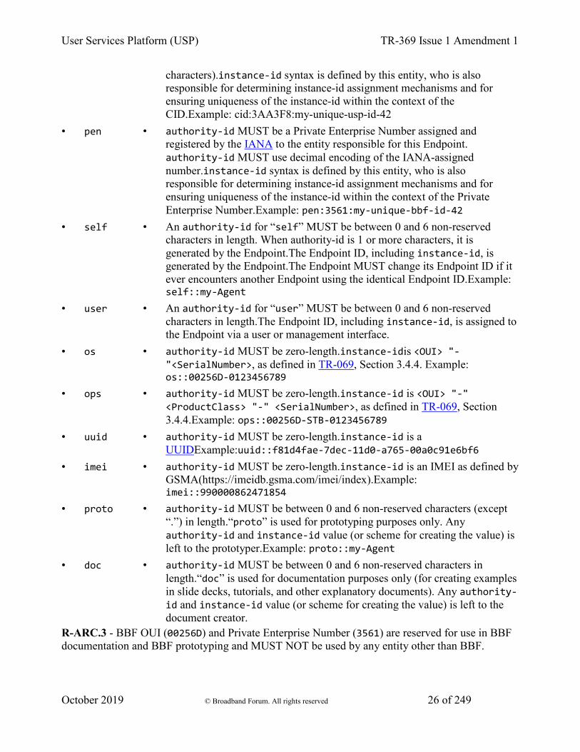
• authority-scheme • usage and rules for authority-id and instance-id
• oui • authority-id MUST be an OUI assigned and registered by the IEEE Registration Authority to the entity responsible for this Endpoint. authority-id MUST use hex encoding of the 24-bit ID (resulting in 6 hex characters). instance-id syntax is defined by this entity, who is also responsible for determining instance-id assignment mechanisms and for ensuring uniqueness of the instance-id within the context of the OUI. Example:oui:00256D:my-unique-bbf-id-42
• cid • authority-id MUST be a CID assigned and registered by the IEEE Registration Authority to the entity responsible for this Endpoint. authority-id MUST use hex encoding of the 24-bit ID (resulting in 6 hex
User Services Platform (USP) TR-369 Issue 1 Amendment 1
October 2019 © Broadband Forum. All rights reserved 26 of 249
characters).instance-id syntax is defined by this entity, who is also responsible for determining instance-id assignment mechanisms and for ensuring uniqueness of the instance-id within the context of the CID.Example: cid:3AA3F8:my-unique-usp-id-42
• pen • authority-id MUST be a Private Enterprise Number assigned and registered by the IANA to the entity responsible for this Endpoint. authority-id MUST use decimal encoding of the IANA-assigned number.instance-id syntax is defined by this entity, who is also responsible for determining instance-id assignment mechanisms and for ensuring uniqueness of the instance-id within the context of the Private Enterprise Number.Example: pen:3561:my-unique-bbf-id-42
• self • An authority-id for “self” MUST be between 0 and 6 non-reserved characters in length. When authority-id is 1 or more characters, it is generated by the Endpoint.The Endpoint ID, including instance-id, is generated by the Endpoint.The Endpoint MUST change its Endpoint ID if it ever encounters another Endpoint using the identical Endpoint ID.Example: self::my-Agent
• user • An authority-id for “user” MUST be between 0 and 6 non-reserved characters in length.The Endpoint ID, including instance-id, is assigned to the Endpoint via a user or management interface.
• os • authority-id MUST be zero-length.instance-idis <OUI> "-"<SerialNumber>, as defined in TR-069, Section 3.4.4. Example: os::00256D-0123456789
• ops • authority-id MUST be zero-length.instance-id is <OUI> "-" <ProductClass> "-" <SerialNumber>, as defined in TR-069, Section 3.4.4.Example: ops::00256D-STB-0123456789
• uuid • authority-id MUST be zero-length.instance-id is a UUIDExample:uuid::f81d4fae-7dec-11d0-a765-00a0c91e6bf6
• imei • authority-id MUST be zero-length.instance-id is an IMEI as defined by GSMA(https://imeidb.gsma.com/imei/index).Example: imei::990000862471854
• proto • authority-id MUST be between 0 and 6 non-reserved characters (except “.”) in length.“proto” is used for prototyping purposes only. Any authority-id and instance-id value (or scheme for creating the value) is left to the prototyper.Example: proto::my-Agent
• doc • authority-id MUST be between 0 and 6 non-reserved characters in length.“doc” is used for documentation purposes only (for creating examples in slide decks, tutorials, and other explanatory documents). Any authority-id and instance-id value (or scheme for creating the value) is left to the document creator.
R-ARC.3 - BBF OUI (00256D) and Private Enterprise Number (3561) are reserved for use in BBF documentation and BBF prototyping and MUST NOT be used by any entity other than BBF.
User Services Platform (USP) TR-369 Issue 1 Amendment 1
October 2019 © Broadband Forum. All rights reserved 27 of 249
R-ARC.4 - The “proto” and “doc” authority-scheme values MUST NOT be used in production environments.
The “proto” and “doc” values are intended only for prototyping and documentation (tutorials, examples, etc.), respectively.
4.1.3.2 Use of instance-id
R-ARC.5 - instance-id MUST be encoded using only the following characters:
instance-id = unreserved / pct-encoded unreserved = ALPHA / DIGIT / "-" / "." / "_" pct-encoded = "%" HEXDIG HEXDIG
The above expression uses the Augmented Backus-Naur Form (ABNF) notation of RFC2234, including the following core ABNF syntax rules defined by that specification: ALPHA (letters), DIGIT (decimal digits), HEXDIG (hexadecimal). It is taken from RFC3986 as the set of unreserved characters and percent-encoded characters that are acceptable for all components of a URI. This set is also allowed for use in URNs RFC2141, and all MTP headers.
R-ARC.6 - An instance-id value MUST be no more than 50 characters in length.
Shorter values are preferred, as end users could be exposed to Endpoint IDs. Long values tend to create a poor user experience when users are exposed to them.
4.2 Service Elements
“Service Element” is a general term referring to the set of Objects, sub-Objects, commands, events, and parameters that comprise a set of functionality that is manipulated by a Controller on an Agent. An Agent’s Service Elements are represented in a Data Model - the data model representing an Agent’s current state is referred to as its Instantiated Data Model, and the data model representing the Service Elements it supports is called its Supported Data Model. The Supported Data Model is described in a Device Type Definition (DT). An Agent’s Data Model is referenced using Path Names.
4.2.1 Data Models
USP is designed to allow a Controller to manipulate Service Elements on an Agent using a standardized description of those Service Elements. This standardized description is known as an information model, and an information model that is further specified for use in a particular protocol is known as a “Data Model”.
Note: This should be understood by those familiar with CWMP. For those unfamiliar with that protocol, a Data Model is similar to a Management Information Base (MIB) used in the Simple Network Management Protocol (SNMP) or YANG definitions used in NETCONF.
User Services Platform (USP) TR-369 Issue 1 Amendment 1
October 2019 © Broadband Forum. All rights reserved 28 of 249
This version of the specification defines support for the following Data Model(s):
• The Device:2 Data Model
This Data Model is specified in XML. The schema and normative requirements for defining Objects, Parameters, Events, and Commands for the Device:2 Data Model, and for creating Device Type Definitions based on that Data Model, are defined in Broadband Forum TR-106, “Data Model Template for TR-069 Enabled Devices”.
The use of USP with any of the above data models creates some dependencies on specific Objects and Parameters that must be included for base functionality.
4.2.1.1 Instantiated Data Model
An Agent’s Instantiated Data Model represents the Service Elements (and their state) that are currently represented by the Agent. The Instantiated Data Model includes a set of Objects, and the sub-Objects (“children”), Parameters, Events, and Commands associated with those objects.
4.2.1.2 Supported Data Model
An Agent’s Support Data Model represents the Service Elements that an Agent understands. It includes references to the Data Model(s) that define the Objects, Parameters, Events, and Commands implemented by the Service Elements the Agent represents. A Supported Data Model consists of the union of all Device Type Definitions used by the Agent.
4.2.1.3 Objects
Objects are data structures that are defined by their sub-Objects, Parameters, Events, Commands, and creation criteria. They are used to model resources represented by the Agent. Objects may be static (single-instance) or dynamic (a multi-instance Object, or “table”).
4.2.1.3.1 Single-Instance Objects
Static Objects, or “single instance” Objects, are not tables and do not have more than one instance of them in the Agent. They are usually used to group Service Element functionality together to allow for easy definition and addressing.
4.2.1.3.2 Multi-Instance Objects
Dynamic Objects, or “multi-instance” Objects, are those Objects that can be the subject of “create” and “delete” operations (using the Add and Delete messages, respectively), with each instance of the Object represented in the Instantiated Data Model with an Instance Identifier (see below). A

User Services Platform (USP) TR-369 Issue 1 Amendment 1
October 2019 © Broadband Forum. All rights reserved 29 of 249
Multi-Instance Object is also referred to as a “Table”, with each instance of the Object referred to as a “Row”. Multi-Instance Objects can be also the subject of a search.
4.2.1.4 Parameters
Parameters define the attributes or variables of an Object. They are retrieved by a Controller using the read operations of USP and configured using the update operations of USP (the Get and Set messages, respectively). Parameters have data types and are used to store values.
4.2.1.5 Commands
Commands define Object specific methods within the Data Model. A Controller can invoke these methods using the “Operate” message in USP (i.e., the Operate message). Commands have associated input and output arguments that are defined in the Data Model and used when the method is invoked and returned.
4.2.1.6 Events
Events define Object specific notifications within the Data Model. A Controller can subscribe to these events by creating instances of the Subscription table, which are then sent in a Notify Request by the Agent. Events may also have information associated with them that are delivered in the Notify Request - this information is defined with the Event in the Data Model.
4.2.2 Path Names
A Path Name is a fully qualified reference to an Object, Object Instance, or Parameter in an Agent’s instantiated or Supported Data Model. The syntax for Path Names is defined in TR-106.
R-ARC.7 - All USP endpoints MUST support the Path Name syntax as defined in TR-106.
Path Names are represented by a hierarchy of Objects (“parents”) and sub-Objects (“children”), separated by the dot “.” character, ending with a parameter if referencing a parameter path. There are six different types of Path Names used to address the data model of an Agent:
1. Object Path - This is a Path Name of either a single-instance (“static”) Object, or the Path Name to a Data Model Table (i.e., a Multi-Instance Object). An Object Path ends in a “.” Character (as specified in TR-106), except when used in a reference parameter. When addressing a Table in the Agent’s Supported Data Model that contains one or more Multi-Instance Objects in the Path Name, the sequence “{i}” is used as a placeholder (see the GetSupportedDM message).
2. Object Instance Path - This is a Path Name to a Row in a Table in the Agent’s Instantiated Data Model (i.e., an Instance of a Multi-Instance Object). It uses an Instance Identifier to

User Services Platform (USP) TR-369 Issue 1 Amendment 1
October 2019 © Broadband Forum. All rights reserved 30 of 249
address a particular Instance of the Object. An Object Instance Path ends in a “.” Character (as specified in TR-106), except when used in a reference parameter.
3. Parameter Path - This is a Path Name of a particular Parameter of an Object.
4. Command Path - This is a Path Name of an Object defined Operation.
5. Event Path - This is a Path Name of an Object defined Event.
6. Search Path - This is a Path Name that contains search criteria for addressing a set of Multi-Instance Objects and/or their Parameters. A Search Path may contain a Search Expression or Wildcard.
This creates two functions of Path Names: Addressing and Searching. The first five paths are used for addressing a particular Object, Parameter, Command, or Event. A Search Path uses Searching to return a set of Object Instances and/or their Parameters. When addressing, the expectation is that the Path Name will resolve to either 0 or 1 instance (and depending on the context, 0 instances could be an error). When searching, the expectation is that the Search Path will resolve to 0, 1, or many instances (and depending on the context, 0 instances is often not an error).
NOTE: When resolving a Path Name, the Agent is expected to use locally cached information and/or information that can be obtained rapidly and cheaply. Specifically, there is no expectation that the Agent would issue a network request in order to resolve a Path Name.
NOTE: Obviously only one form of addressing or searching can be used for a given Instance Identifier in a Path Name, but different forms of addressing can be used if more than one Instance Identifier needs to be specified in a Path Name.
For example, the following Path Name uses Unique Key Addressing for the Interface table but a Search Expression for the IPv4Address table to select Enabled IPv4 Addresses associated with the “eth0” IP Interface:
Device.IP.Interface.[Name=="eth0"].IPv4Address.[Status=="Enabled"].IPAddress
4.2.2.1 Relative Paths
Several USP messages make use of relative paths to address Objects or Parameters. A relative path is used to address the child Objects and parameters of a given Object Path or Object Instance Path. To build a Path Name using a Relative Path, a USP endpoint uses a specified Object Path or Object Instance Path, and concatenates the Relative Path. This allows some efficiency in Requests and Responses when passing large numbers of repetitive Path Names. This relative path may include instance identifiers to Multi-Instance Objects.
For example, for an Object Path of:
Device.WiFi.Radio.1.
Relative paths would include parameters:
User Services Platform (USP) TR-369 Issue 1 Amendment 1
October 2019 © Broadband Forum. All rights reserved 31 of 249
Status
SupportedStandards
OperatingStandards
Etc., as well as the following sub-Object and its parameters:
Stats.BytesSent
Stats.BytesReceived
Etc.
4.2.2.2 Using Instance Identifiers in Path Names
4.2.2.2.1 Addressing by Instance Number
Instance Number Addressing allows an Object Instance to be addressed by using its Instance Number in the Path Name. An Instance Number is expressed in the Path Name as a positive integer (>=1) with no additional surrounding characters. The Instance Number assigned by the Agent is arbitrary.
R-ARC.8 - The assigned Instance Number MUST persist unchanged until the Object Instance is subsequently deleted (either by the USP Delete message or through some external mechanism). This implies that the Instance Number MUST persist across a reboot of the Agent, and that the Agent MUST NOT allow the Instance Number of an existing Object Instance to be modified by an external source.
For example, the Device.IP.Interface table entry with an Instance Number of 3 would be addressed with the following Path Name: Device.IP.Interface.3.
4.2.2.2.2 Addressing by Unique Key
Key-based addressing allows an Object Instance to be addressed by using a Unique Key (as defined in Device:2) in the Path Name. This is possible since once a Parameter that is part of a unique key has its value set, then that value is immutable for the life of the Object that contains the Parameter.
For example, the Device.IP.Interface table has 2 separate unique keys; Name and Alias.
Unique Keys used for addressing are expressed in the Path Name by using square brackets surrounding a string that contains the name and value of the Unique Key parameter using the equivalence operator (==).
If an Object has a compound unique key (multiple parameters included within the same unique key), then all keys must be present in the Instance Identifier and concatenated by the AND (&&)
User Services Platform (USP) TR-369 Issue 1 Amendment 1
October 2019 © Broadband Forum. All rights reserved 32 of 249
logical operator (the order of the parameters does not have to follow the order of the parameters as defined in the unique key element as defined in Device:2).
NOTE: Addressing by Unique Key uses the same format as Searching with Expressions (see below). If for a compound unique key expression a key component is omitted it is no longer addressing by unique key but becomes a search with expressions.
For example, the Device.NAT.PortMapping table has a compound unique key consisting of RemoteHost, ExternalPort, and Protocol, which would be addressed with the following Path Name:
Device.NAT.PortMapping.[RemoteHost==""&&ExternalPort==0&&Protocol=="TCP"].
4.2.3 Searching
Searching is a means of matching 0, 1 or many instances of a Multi-Instance Object by using the properties of Object. Searching can be done with Expressions or Wildcards.
4.2.3.1 Searching with Expressions
Search paths that use expression are enclosed in square brackets as the Instance Identifier within a Path Name.
R-ARC.9 - An Agent MUST return Path Names that include all Object Instances that match the criteria of a given Search Path.
The basic format of a Search Path is:
Device.IP.Interface.[<expression>].Status
An Expression consists of one or more Expression Components that are concatenated by the AND (&&) logical operator (NOTE: the OR logical operator is not supported).
The basic format of a Search Path with the Expression element expanded is:
Device.IP.Interface.[<expression component>&&<expression component>].Status
An Expression Component is a combination of an Expression Parameter followed by an Expression Operator followed by an Expression Constant.
The basic format of a Search Path with the Expression Component element expanded is:
Device.IP.Interface.[<expression parameter><expression operator><expression constant>].Status
For example, Device.IP.Interface.[intf].IPv4Address.[addr].IPAddress means that the “intf” Expression represents the instances of the Device.IP.Interface.{i} Object whereas the
User Services Platform (USP) TR-369 Issue 1 Amendment 1
October 2019 © Broadband Forum. All rights reserved 33 of 249
“addr” Expression represents the instances of the Device.IP.Interface.{i}.IPv4Address.{i} Object.
Further, this relative path can’t include any child tables. (NOTE: this is never necessary because any child tables that need to be referenced in the Search Path can and should have their own Expression)
An Expression Operator dictates how the Expression Component will be evaluated. The supported operators include: equals (==), not equals (!=), less than (<), greater than (>), less than or equal (<=), and greater than or equal (>=).
Note: When comparing values of type dateType, the values are presumed to be converted to their numeric equivalent before comparison.
An Expression Parameter will always be of the type defined in the data model. Expression operators will only evaluate for appropriate data types. The literal value representations for all data types are found in TR-106. For string, boolean and enumeration types, only the ‘==’ and ‘!=’ operators are valid.
The Expression Constant is the value that the Expression Parameter is being evaluated against; Expression Parameters must match the type as defined for the associated Parameter in TR-181.
Note: String values are enclosed in double quotes. In order to allow a string value to contain double quotes, quote characters can be percent-escaped as %22 (double quote). Therefore, a literal percent character has to be quoted as %25.
4.2.3.1.1 Search Expression Examples
Valid Searches:
• Status for all IP Interfaces with a “Normal” type:
• Device.IP.Interface.[Type=="Normal"].Status
• IPv4 Addresses for all IP Interfaces with a Normal type and a Static addressing type:
• Device.IP.Interface.[Type=="Normal"].IPv4Address.[AddressingType=="Static"].IPAddress
• IPv4 Addresses for all IP Interfaces with a Normal type and Static addressing type that have at least 1 Error Sent
• Device.IP.Interface.[Type=="Normal"&&Stats.ErrorsSent>0].IPv4Address.[AddressingType=="Static"].IPAddress
Searches that are NOT VALID:
• Invalid because the Expression is empty:
User Services Platform (USP) TR-369 Issue 1 Amendment 1
October 2019 © Broadband Forum. All rights reserved 34 of 249
• Device.IP.Interface.[].
• Invalid because the Expression Component has an Expression Parameter that descends into a child table (always need to use a separate Expression Variable for each child table instance):
• Device.IP.Interface.[Type=="Normal"&&IPv4Address.*.AddressingType=="Static"].Status
• Invalid because the search expression uses curly brackets:
• Device.IP.Interface.{Type=="Normal"}.Status
4.2.3.2 Searching by Wildcard
Wildcard-based searching is a means of matching all currently existing Instances (whether that be 0, 1 or many instances) of a Multi-Instance Object by using a wildcard character “*” in place of the Instance Identifier.
R-ARC.10 - An Agent MUST return Path Names that include all Object Instances that are matched by the use of a Wildcard.
Examples:
All parameters for all IP Interfaces that currently exist
Device.IP.Interface.*.
Type of each IP Interface that currently exists
Device.IP.Interface.*.Type
4.2.4 Other Path Decorators
4.2.4.1 Reference Following
Device:2 contains Parameters that reference other Parameters or Objects. The Reference Following mechanism allows references to Objects (not Parameters) to be followed from inside a single Path Name. Reference Following is indicated by a “+” character after the name of the Parameter that is referencing the Object followed by a “.”, followed by Objects or Parameters that are children of the Referenced Object.
For example, Device.NAT.PortMapping.{i}.Interface references an IP Interface Object (Device.IP.Interface.{i}.) and that Object has a Parameter called “Name”. With Reference Following, a Path Name of Device.NAT.PortMapping.1.Interface+.Name references the “Name” Parameter of the Interface Object that the PortMapping is associated with (i.e. it is the equivalent of using Device.IP.Interface.1.Name as the Path Name.
User Services Platform (USP) TR-369 Issue 1 Amendment 1
October 2019 © Broadband Forum. All rights reserved 35 of 249
The steps that are executed by the Agent when following the reference in this example would be:
1. Retrieve the appropriate instance of the PortMapping Object based on the Instance Number Addressing information
2. Retrieve the value of the reference parameter Parameter that contains the reference, Interface, which in this case has the value “Device.IP.Interface.1”
3. Replace the preceding path (Device.NAT.PortMapping.1.Interface+) with the value retrieved in Step 2
4. Append the remainder of the Path Name (.Name), which builds the Path Name: Device.IP.Interface.1.Name
5. Use Device.IP.Interface.1.Name as the Path Name for the action
*Note: It should be noted that according to the Device:2 Schema, reference parameters:
• Always contain Path Names (not Search Expressions)
• When configured, can be configured using Path Names using Instance Number Addressing or Unique-Key Addressing, however:
• When the value of a reference parameter is read, all Instance Identifiers are returned as Instance Numbers.*
R-ARC.11 - A USP Agent MUST support the ability to use Key-based addressing in reference values.
For example, the following paths might illustrate a reference to the same object (defined as having the KeyParam parameter as unique key) instance using an Instance Number and then a key value:
• Object.SomeReferenceParameter = “Object.FooObject.5”
• Object.SomeReferenceParameter = “Object.FooObject.[KeyParam=="KeyValueForInstance5"]”
In the first example, the reference points to the FooObject with Instance Number 5. In the second example, the reference points to the FooObject with a KeyParam value of “KeyValueForInstance5”.
R-ARC.12 - The following requirements relate to reference types and the associated Agent behavior:
• An Agent MUST reject an attempt to set a strong reference parameter if the new value does not reference an existing parameter or object.
• An Agent MUST NOT reject an attempt to set a weak reference parameter because the new value does not reference an existing parameter or object.
• An Agent MUST change the value of a non-list-valued strong reference parameter to a null reference when a referenced parameter or object is deleted.
User Services Platform (USP) TR-369 Issue 1 Amendment 1
October 2019 © Broadband Forum. All rights reserved 36 of 249
• An Agent MUST remove the corresponding list item from a list-valued strong reference parameter when a referenced parameter or object is deleted.
• An Agent MUST NOT change the value of a weak reference parameter when a referenced parameter or object is deleted.
4.2.4.1.1 List of References
The USP data models have Parameters whose values contain a list of references to other Parameters or Objects. This section explains how the Reference Following mechanism allows those references to be followed from inside a single Path Name. The Reference Following syntax as defined above still applies, but it is preceded by a means of referencing a specific instance within the list. The additional syntax consists of a “#” character followed by list item number (1-indexed), which is placed between the name of the Parameter that contains the list of references and the “+” that indicates that the reference should be followed. To follow all references in the list, the endpoint can specify a “#” character followed by a wildcard (“*”) character and the “+” character to follow the reference (i.e., “ReferenceParameter#*+”).
For example, Device.WiFi.SSID.{i}.LowerLayers references a list of WiFi Radio Object (defined as Device.WiFi.Radio.{i}.) Instances that are associated with the SSID. This Object has a Name Parameter; so when following the first reference in the list of references a Path Name of Device.WiFi.SSID.1.LowerLayers#1+.Name references the Name of the WiFi Radio associated with this SSID Object Instance.
The steps that are executed by the Agent when following the reference in this example would be:
1. Retrieve the appropriate Device.WiFi.SSID.{i} instance based on the Instance Number Addressing information
2. Retrieve the value of the LowerLayers Parameter, which in this case has a value of “Device.WiFi.Radio.1, Device.WiFi.Radio.2”
3. Retrieve the first list item within the value retrieved in Step 2 (i.e., “Device.WiFi.Radio.1”)
4. Replace the preceding path (Device.WiFi.SSID.1.LowerLayers#1+) with the value retrieved in Step 3
5. Append the remainder of the Path Name (.Name), resulting in a Path Name of: Device.WiFi.Radio.1.Name
6. Use Device.WiFi.Radio.1.Name as the Path Name for the action
4.2.4.1.2 Search Expressions and Reference Following
The Reference Following and Search Expression mechanisms can be combined.
User Services Platform (USP) TR-369 Issue 1 Amendment 1
October 2019 © Broadband Forum. All rights reserved 37 of 249
For example, reference the Signal Strength of all WiFi Associated Devices using the “ac” Operating Standard on the “MyHome” SSID, you would use the Path Name:
Device.WiFi.AccessPoint.[SSIDReference+.SSID=="MyHome"].AssociatedDevice.[OperatingStandard=="ac"].SignalStrength
4.2.4.2 Operations and Command Path Names
The Operate message allows a USP Controller to execute Commands defined in the USP data models. Commands are synchronous or asynchronous operations that don’t fall into the typical REST-based concepts of CRUD-N that have been incorporated into the protocol as specific messages. Commands are addressed like Parameter Paths that end with parentheses “()” to symbolize that it is a Command.
For example: Device.IP.Interface.[Name=="eth0"].Reset()
4.2.4.2.1 Event Path Names
The Notify request allows a type of generic event (called Event) message that allows a USP Agent to emit events defined in the USP data models. Events are defined in and related to Objects in the USP data models like commands. Events are addressed like Parameter Paths that end with an exclamation point “!” to symbolize that it is an Event.
For example: Device.Boot!
4.2.5 Data Model Path Grammar
Expressed as a Backus-Naur Form (BNF) for context-free grammars, the path lexical rules for referencing the Instantiated Data Model are:
idmpath ::= objpath | parampath | cmdpath | evntpath | searchpath objpath ::= name '.' (name (('.' inst)|(reffollow '.' name) )? '.')* parampath ::= objpath name cmdpath ::= objpath name '()' evntpath ::= objpath name '!' inst ::= posnum | expr | '*' expr ::= '[' (exprcomp ( '&&' exprcomp )*) ']' exprcomp ::= relpath oper value relpath ::= name (reffollow? '.' name )* reffollow ::= ( '#' (posnum | '*') '+' )| '+' oper ::= '==' | '!=' | '<' | '>' | '<=' | '>=' value ::= literal | number name ::= [A-Za-z_] [A-Za-z_0-9]* literal ::= '"' [^"]* '"' posnum ::= [1-9] [0-9]* number ::= '0' | ( '-'? posnum )
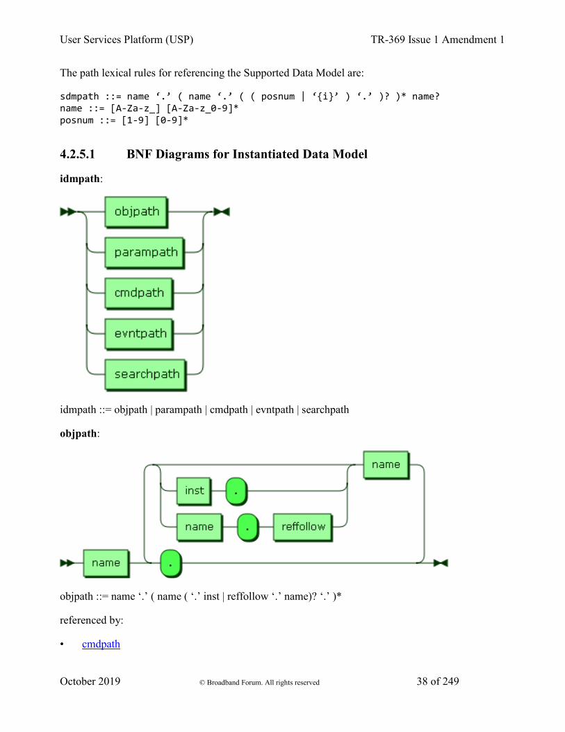
User Services Platform (USP) TR-369 Issue 1 Amendment 1
October 2019 © Broadband Forum. All rights reserved 38 of 249
The path lexical rules for referencing the Supported Data Model are:
sdmpath ::= name ‘.’ ( name ‘.’ ( ( posnum | ‘{i}’ ) ‘.’ )? )* name? name ::= [A-Za-z_] [A-Za-z_0-9]* posnum ::= [1-9] [0-9]*
4.2.5.1 BNF Diagrams for Instantiated Data Model
idmpath:
idmpath ::= objpath | parampath | cmdpath | evntpath | searchpath
objpath:
objpath ::= name ‘.’ ( name ( ‘.’ inst | reffollow ‘.’ name)? ‘.’ )*
referenced by:
• cmdpath

User Services Platform (USP) TR-369 Issue 1 Amendment 1
October 2019 © Broadband Forum. All rights reserved 39 of 249
• evntpath
• idmpath
• parampath
parampath:
parampath ::= objpath name
referenced by:
• idmpath
cmdpath:
cmdpath ::= objpath name ‘()’
referenced by:
• idmpath
evntpath:
evntpath ::= objpath name ‘!’
referenced by:
• idmpath
inst:
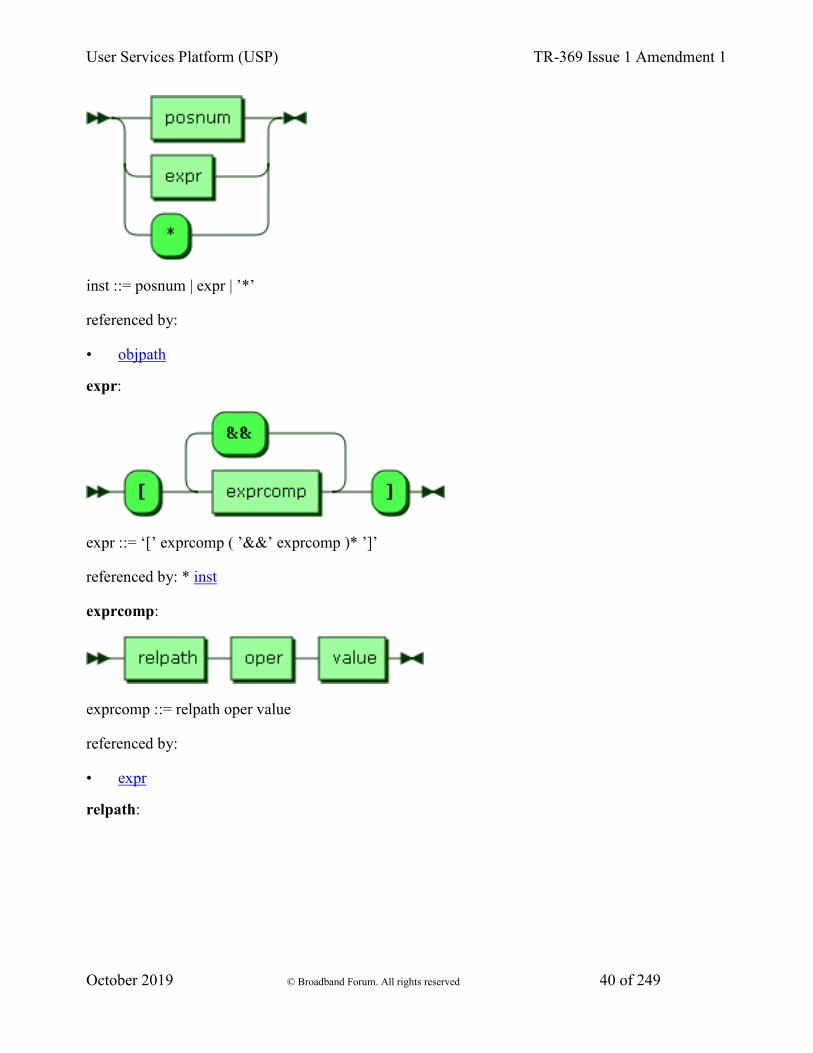
User Services Platform (USP) TR-369 Issue 1 Amendment 1
October 2019 © Broadband Forum. All rights reserved 40 of 249
inst ::= posnum | expr | ’*’
referenced by:
• objpath
expr:
expr ::= ‘[’ exprcomp ( ’&&’ exprcomp )* ’]’
referenced by: * inst
exprcomp:
exprcomp ::= relpath oper value
referenced by:
• expr
relpath:
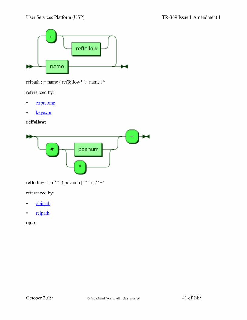
User Services Platform (USP) TR-369 Issue 1 Amendment 1
October 2019 © Broadband Forum. All rights reserved 41 of 249
relpath ::= name ( reffollow? ‘.’ name )*
referenced by:
• exprcomp
• keyexpr
reffollow:
reffollow ::= ( ‘#’ ( posnum | ’*’ ) )? ‘+’
referenced by:
• objpath
• relpath
oper:
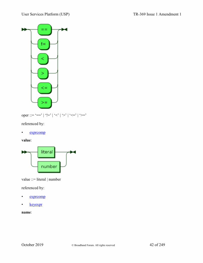
User Services Platform (USP) TR-369 Issue 1 Amendment 1
October 2019 © Broadband Forum. All rights reserved 42 of 249
oper ::= ‘==’ | ‘!=’ | ‘<’ | ‘>’ | ‘<=’ | ‘>=’
referenced by:
• exprcomp
value:
value ::= literal | number
referenced by:
• exprcomp
• keyexpr
name:

User Services Platform (USP) TR-369 Issue 1 Amendment 1
October 2019 © Broadband Forum. All rights reserved 43 of 249
name ::= [A-Za-z_] [A-Za-z_0-9]*
referenced by:
• cmdpath
• evntpath
• objpath
• parampath
• relpath
literal:
literal ::= ‘"’ [^"]* ‘"’
referenced by:
• value

User Services Platform (USP) TR-369 Issue 1 Amendment 1
October 2019 © Broadband Forum. All rights reserved 44 of 249
number:
number ::= ‘0’ | ‘-’? posnum
referenced by:
• value
posnum:
posnum ::= [1-9] [0-9]*
referenced by:
• inst
• number
• reffollow
4.2.5.2 BNF Diagrams for Supported Data Model
sdmpath:
sdmpath ::= name ‘.’ ( name ‘.’ ( ( posnum | ‘{i}’ ) ‘.’ )? )* name?
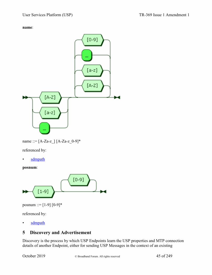
User Services Platform (USP) TR-369 Issue 1 Amendment 1
October 2019 © Broadband Forum. All rights reserved 45 of 249
name:
name ::= [A-Za-z_] [A-Za-z_0-9]*
referenced by:
• sdmpath
posnum:
posnum ::= [1-9] [0-9]*
referenced by:
• sdmpath
5 Discovery and Advertisement Discovery is the process by which USP Endpoints learn the USP properties and MTP connection details of another Endpoint, either for sending USP Messages in the context of an existing
User Services Platform (USP) TR-369 Issue 1 Amendment 1
October 2019 © Broadband Forum. All rights reserved 46 of 249
relationship (where the Controller’s USP Endpoint Identifier, credentials, and authorized Role are all known to the Agent) or for the establishment of a new relationship.
Advertisement is the process by which USP Endpoints make their presence known (or USP Endpoint presence is made known) to other USP Endpoints.
5.1 Controller Information
An Agent that has a USP relationship with a Controller needs to know that Controller’s Endpoint Identifier, credentials, and authorized Role.
An Agent that has a USP relationship with a Controller needs to obtain information that allows it to determine at least one MTP, IP address, port, and resource path (if required by the MTP) of the Controller. This may be a URL with all of these components, a FQDN that resolves to provide all of these components via DNS-SD records, or mDNS discovery in the LAN.
Example mechanisms for configuration include but are not limited to:
• Pre-configured in firmware
• Configured by an already-known-and-trusted Controller
• Configured through a separate bootstrap mechanism such as a user interface or other management interface.
• DHCP, DNS, or mDNS discovery.
R-DIS.0 - An Agent that supports USP configuration of Controllers MUST implement the Device.LocalAgent.Controller Object as defined in The Device:2 Data Model.
The Agent can be pre-configured with trusted root certificates or trusted certificates to allow authentication of Controllers. Other trust models are also possible, where an Agent without a current Controller association will trust the first discovered Controller, or where the Agent has a UI that allows a User to indicate whether a discovered Controller is authorized to configure that Agent.
5.2 Required Agent Information
A Controller that has a relationship with an Agent needs to know the Agent’s Endpoint Identifier, connectivity information for the Agent’s MTP(s), and credentials.
Controllers acquires this information upon initial connection by an Agent, though a LAN based Controller may acquire an Agent’s MTP information through mDNS Discovery. It is each Controller’s responsibility to maintain a record of known Agents.
5.3 Use of DHCP for Acquiring Controller Information
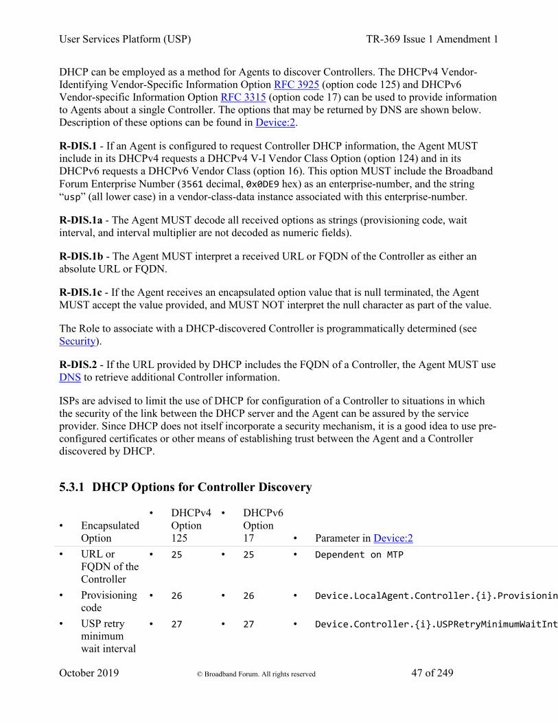
User Services Platform (USP) TR-369 Issue 1 Amendment 1
October 2019 © Broadband Forum. All rights reserved 47 of 249
DHCP can be employed as a method for Agents to discover Controllers. The DHCPv4 Vendor-Identifying Vendor-Specific Information Option RFC 3925 (option code 125) and DHCPv6 Vendor-specific Information Option RFC 3315 (option code 17) can be used to provide information to Agents about a single Controller. The options that may be returned by DNS are shown below. Description of these options can be found in Device:2.
R-DIS.1 - If an Agent is configured to request Controller DHCP information, the Agent MUST include in its DHCPv4 requests a DHCPv4 V-I Vendor Class Option (option 124) and in its DHCPv6 requests a DHCPv6 Vendor Class (option 16). This option MUST include the Broadband Forum Enterprise Number (3561 decimal, 0x0DE9 hex) as an enterprise-number, and the string “usp” (all lower case) in a vendor-class-data instance associated with this enterprise-number.
R-DIS.1a - The Agent MUST decode all received options as strings (provisioning code, wait interval, and interval multiplier are not decoded as numeric fields).
R-DIS.1b - The Agent MUST interpret a received URL or FQDN of the Controller as either an absolute URL or FQDN.
R-DIS.1c - If the Agent receives an encapsulated option value that is null terminated, the Agent MUST accept the value provided, and MUST NOT interpret the null character as part of the value.
The Role to associate with a DHCP-discovered Controller is programmatically determined (see Security).
R-DIS.2 - If the URL provided by DHCP includes the FQDN of a Controller, the Agent MUST use DNS to retrieve additional Controller information.
ISPs are advised to limit the use of DHCP for configuration of a Controller to situations in which the security of the link between the DHCP server and the Agent can be assured by the service provider. Since DHCP does not itself incorporate a security mechanism, it is a good idea to use pre-configured certificates or other means of establishing trust between the Agent and a Controller discovered by DHCP.
5.3.1 DHCP Options for Controller Discovery
• Encapsulated Option
• DHCPv4 Option 125
• DHCPv6 Option 17 • Parameter in Device:2
• URL or FQDN of the Controller
• 25 • 25 • Dependent on MTP
• Provisioning code
• 26 • 26 • Device.LocalAgent.Controller.{i}.Provisionin
• USP retry minimum wait interval
• 27 • 27 • Device.Controller.{i}.USPRetryMinimumWaitInt

User Services Platform (USP) TR-369 Issue 1 Amendment 1
October 2019 © Broadband Forum. All rights reserved 48 of 249
• USP retry interval multiplier
• 28 • 28 • Device.Controller.{i}.USPRetryIntervalMultip
5.4 mDNS
R-DIS.3 - If mDNS discovery is supported by a USP Endpoint, the USP Endpoint MUST implement mDNS client and server functionality as defined in RFC 6762.
R-DIS.4 - If mDNS advertisement for a MTP is enabled on an Endpoint, the Endpoint MUST listen for messages using that MTP from other Endpoints requesting establishment of USP communication over that MTP.
R-DIS.5 - If mDNS is enabled, a USP Endpoint MUST use mDNS to resolve a FQDN with domain “.local.”.
In general, the expectation is that Agents will advertise themselves so they will be discoverable by Controllers. Controllers are not expected to advertise themselves, but are expected to discover Agents and respond to applicable mDNS requests from Agents. Agents will use mDNS to resolve a Controller “.local.” FQDN (and get DNS-SD records) when the Agent needs to send a Notification to that Controller.
5.5 DNS
Requirements for implementation of a DNS client and configuration of the DNS client with DNS server address(es) (through static configuration, DHCPv4, DHCPv6, or Router Solicitation) are not provided. These are sufficiently well-known that they were not considered necessary for this specification. If the Agent knows of no DNS Server, it cannot do DNS resolution.
R-DIS.6 - If DNS is enabled, an Endpoint MUST use DNS to resolve a FQDN with domain other than ones used for mDNS (R-DIS.5)
R-DIS.7 - If the Agent is resolving an FQDN for a Controller, and the MTP or resource path are unknown, the Agent MUST request DNS-SD information (PTR, SRV and TXT resource records) in addition to A, AAAA or other resource records it is programmatically set to request.
5.5.1 DNS-SD Records
DNS Service Discovery (DNS-SD) RFC 6763 is a mechanism for naming and structuring of DNS resource records to facilitate service discovery. It can be used to create DNS records for USP Endpoints, so they can be discoverable via DNS PTR queries RFC 1035 or Multicast DNS (mDNS) RFC 6762. DNS-SD uses DNS SRV and TXT records to express information about “services”, and DNS PTR records to help locate the SRV and TXT records. To discover these DNS records, DNS or mDNS queries can be used. [RFC 6762] recommends using the query type PTR to get both the SRV and TXT records. A and AAAA records will also be returned, for address resolution.
User Services Platform (USP) TR-369 Issue 1 Amendment 1
October 2019 © Broadband Forum. All rights reserved 49 of 249
The format of a DNS-SD Service Instance Name (which is the resource record (RR) Name of the DNS SRV and TXT records) is “<Instance>.<Service>.<Domain>”. <Instance> will be the USP Endpoint Identifier of the USP Endpoint.
R-DIS.8 - USP Endpoint DNS-SD records MUST include the USP Endpoint Identifier of the USP Endpoint as the DNS-SD Service Instance Name.
Service Name values registered by BBF with IANA used by USP are shown below. As described in RFC 6763, the <Service> part of a Service Instance Name is constructed from these values as “_<Service Name>._<Transport Protocol>” (e.g., “_usp-agt-coap._udp”).
5.5.2 IANA-Registered USP Service Names
• Service Name • Transport Protocol • MTP • Type of USP Endpoint • usp-agt-coap • udp • CoAP • Agent • usp-ctr-coap • udp • CoAP • Controller • usp-agt-ws • tcp • WebSocket • Agent • usp-ctr-ws • tcp • WebSocket • Controller • usp-agt-stomp • tcp • STOMP • Agent • usp-ctr-stomp • tcp • STOMP • Controller DNS PTR records with a service subtype identifier (e.g., ._<subtype>._usp-agt-coap._udp.<Domain>) in the RR can be used to provide searchable simple (single layer) functional groupings of USP Agents. The registry of subtypes for Service Names registered by BBF is listed at www.broadband-forum.org/assignments. DNS SRV and TXT records can be pointed to by multiple PTR records, which allow a USP Endpoint to potentially be discoverable as belonging to various functional groupings.
DNS TXT records allow for a small set of additional information to be included in the reply sent to the querier. This information cannot be used as search criteria. The registry of TXT record attributes for BBF Service Names are listed at www.broadband-forum.org/assignments.
R-DIS.9 - Agent DNS-SD records MUST include a TXT record with the “path” and “name” attributes.
R-DIS.10 - The “name” attribute included in the Agent DNS-SD records MUST be identical to the .FriendlyName parameter defined in Device:2, if the FriendlyName parameter is implemented.
R-DIS.11 - Controller DNS-SD records MUST include a TXT record with the “path” attribute.
The “path” attribute is dependent on each Message Transfer Protocol.
The TXT record can include other attributes defined in the TXT record attribute registry, as well.
Whether a particular USP Endpoint responds to DNS or mDNS queries or populates (through configuration or mDNS advertisement) their information in a local DNS-SD server can be a
User Services Platform (USP) TR-369 Issue 1 Amendment 1
October 2019 © Broadband Forum. All rights reserved 50 of 249
configured option that can be enabled/disabled, depending on the intended deployment usage scenario.
5.5.3 Example Controller Unicast DNS-SD Resource Records
; One PTR record for each supported MTP _usp-ctr-coap._udp.host.example.com PTR <USP ID>._usp-ctr-coap._udp.example.com. ; One SRV+TXT (DNS-SD Service Instance) record for each supported MTP <USP ID>._usp-ctr-coap._udp.example.com. SRV 0 1 443 host.example.com. <USP ID>._usp-ctr-coap._udp.example.com. TXT "path=<pathname>" ; Controller A and AAAA records host.example.com. A 192.0.2.200 host.example.com. AAAA 2001:db8::200
5.5.4 Example Agent Multicast DNS-SD Resource Records
; One PTR record (DNS-SD Service) for each supported MTP _usp-agt-coap._udp PTR <USP ID>._usp-agt-coap._udp.local. ; One PTR record (DNS-SD Service Subtype) for each supported MTP per device type _iot-device._sub._usp-agt-coap._udp PTR <USP ID>._usp-agt-coap._udp.local. _gateway._sub._usp-agt-coap._udp PTR <USP ID>._usp-agt-coap._udp.local. ; One SRV+TXT record (DNS-SD Service Instance) for each supported MTP <USP ID>._usp-agt-coap._udp.local. SRV 0 1 5694 <USP ID>.local. <USP ID>._usp-agt-coap._udp.local. TXT "path=<pathname>" "name=kitchen light" ; Agent A and AAAA records <USP ID>.local. A 192.0.2.100 <USP ID>.local. AAAA 2001:db8::100
5.5.5 Example Controller Multicast DNS-SD Resource Records
LAN Controllers do not need to have PTR records, as they will only be queried using the DNS-SD instance identifier of the Controller.
; One SRV+TXT record (DNS-SD Service Instance) for each supported MTP <USP ID>._usp-ctr-coap._tcp.local. SRV 0 1 443 <USP ID>.local. <USP ID>._usp-ctr-coap._tcp.local. TXT "path=<pathname>"
User Services Platform (USP) TR-369 Issue 1 Amendment 1
October 2019 © Broadband Forum. All rights reserved 51 of 249
; Controller A and AAAA records <USP ID>.local. A 192.0.2.200 <USP ID>.local. AAAA 2001:db8::200
5.6 Using the SendOnBoardRequest() operation and OnBoardRequest notification
An “OnBoardRequest” notification can be sent by an Agent to a Controller to begin an on-boarding process (for example, when the Agent first comes online and discovers a Controller using DHCP). Its use is largely driven by policy, but there is a mechanism other Controllers can use to ask an Agent to send “OnBoardRequest” to another Controller: the SendOnBoardRequest() command is defined in the Device:2. See section on notify messages for additional information about the OnBoardRequest notification.
6 Message Transfer Protocols USP messages are sent between Endpoints over one or more Message Transfer Protocols.
Note: Message Transfer Protocol was a term adopted to avoid confusion with the term “Transport”, which is often overloaded to include both application layer (i.e. CoAP) and the actual OSI Transport layer (i.e. UDP). Throughout this document, Message Transfer Protocol (MTP) refers to application layer transport.
The requirements for each individual Message Transfer Protocol is covered in a section of this document. This version of the specification includes definitions for:
• The Constrained Application Protocol (CoAP)
• WebSockets
• The Simple Text-Oriented Messaging Protocol
• MQ Telemetry Transport (MQTT)
6.1 Supporting Multiple MTPs
Agents and Controllers may support more than one MTP. When an Agent supports multiple MTPs, the Agent may be configured with parameters for reaching a particular Controller across more than one MTP. When an Agent needs to send a Notification to such a Controller, the Agent can be designed (or possibly configured) to select a particular MTP, to try sending the Notification to the Controller on all MTPs simultaneously, or to try MTPs sequentially. USP has been designed to allow Endpoints to recognize when they receive a duplicate Message and to discard any duplicates. Endpoints will always send responses on the same MTP where the Message was received.
6.2 Securing MTPs

User Services Platform (USP) TR-369 Issue 1 Amendment 1
October 2019 © Broadband Forum. All rights reserved 52 of 249
This specification places the following requirement for encrypting MTP headers and payloads on USP implementations that are intended to be used in environments where USP Messages will be transported across the Internet:
R-MTP.0 – The Message Transfer Protocol MUST use secure transport when USP Messages cross inter-network boundaries.
For example, it may not be necessary to use MTP layer security when within an end-user’s local area network (LAN). It is necessary to secure transport to and from the Internet, however. If the device implementer can reasonably expect Messages to be transported across the Internet when the device is deployed, then the implementer needs to ensure the device supports encryption of all MTP protocols.
MTPs that operate over UDP will be expected to implement, at least, DTLS 1.2 as defined in RFC 6347.
MTPs that operate over TCP will be expected to implement, at least, TLS 1.2 as defined in RFC 5246.
Specific requirements for implementing these are provided in the individual MTP sections.
R-MTP.1 – When TLS or DTLS is used to secure an MTP, an Agent MUST require the MTP peer to provide an X.509 certificate.
R-MTP.2 - An Agent capable of obtaining absolute time SHOULD wait until it has accurate absolute time before establishing TLS or DTLS encryption to secure MTP communication. If an Agent for any reason is unable to obtain absolute time, it can establish TLS or DTLS without waiting for accurate absolute time. If an Agent chooses to establish TLS or DTLS before it has accurate absolute time (or if it does not support absolute time), it MUST ignore those components of the received X.509 certificate that involve absolute time, e.g. not-valid-before and not-valid-after certificate restrictions.
R-MTP.3 - An Agent that has obtained an accurate absolute time MUST validate those components of the received X.509 certificate that involve absolute time.
R-MTP.4 - When an Agent receives an X.509 certificate while establishing TLS or DTLS encryption of the MTP, the Agent MUST execute logic that achieves the same results as in the decision flow from Figures MTP.1.

User Services Platform (USP) TR-369 Issue 1 Amendment 1
October 2019 © Broadband Forum. All rights reserved 53 of 249
Figure MTP.1 – Receiving a X.509 Certificate
User Services Platform (USP) TR-369 Issue 1 Amendment 1
October 2019 © Broadband Forum. All rights reserved 54 of 249
6.3 Brokered USP Record Errors
MTPs that allow connectivity directly between Endpoints tear down the connection when encountering a USP Record error or other failure caused by the USP Record. This allows such a problem to be signaled to the other Endpoint. MTP protocols where Endpoints connect to a session broker do not tear down the connections to the session broker when encountering USP Record errors. To notify an Endpoint when a failed USP Record was sent, the receiving Endpoint replies with a simple error message.
These error messages are indicated using content type application/vnd.bbf.usp.error. The following error codes (in the range 7100-7199) are defined to allow the error to be more specifically indicated. Requirements for communicating USP Record errors using this content type and these error codes are included in the definitions of brokered MTPs.
• Code • Name • Description • 7100 • Record could not be
parsed • This error indicates the received USP Record could
not be parsed. • 7101 • Secure session
required • This error indicates USP layer Secure Message
Exchange is required. • 7102 • Secure session not
supported • This error indicates USP layer Secure Message
Exchange was indicated in the received Record but is not supported by the receiving Endpoint.
• 7103 • Segmentation and reassembly not supported
• This error indicates segmentation and reassembly was indicated in the received Record but is not supported by the receiving Endpoint.
• 7104 • Invalid Record value • This error indicates the value of at least one Record field was invalid.
7 CoAP Binding The Constrained Application Protocol (CoAP) MTP transfers USP Records between USP Endpoints using the CoAP protocol as defined in RFC 7252. Messages that are transferred between CoAP clients and servers utilize a request/response messaging interaction based on RESTful architectural principles. The following figure depicts the transfer of the USP Records between USP Endpoints.
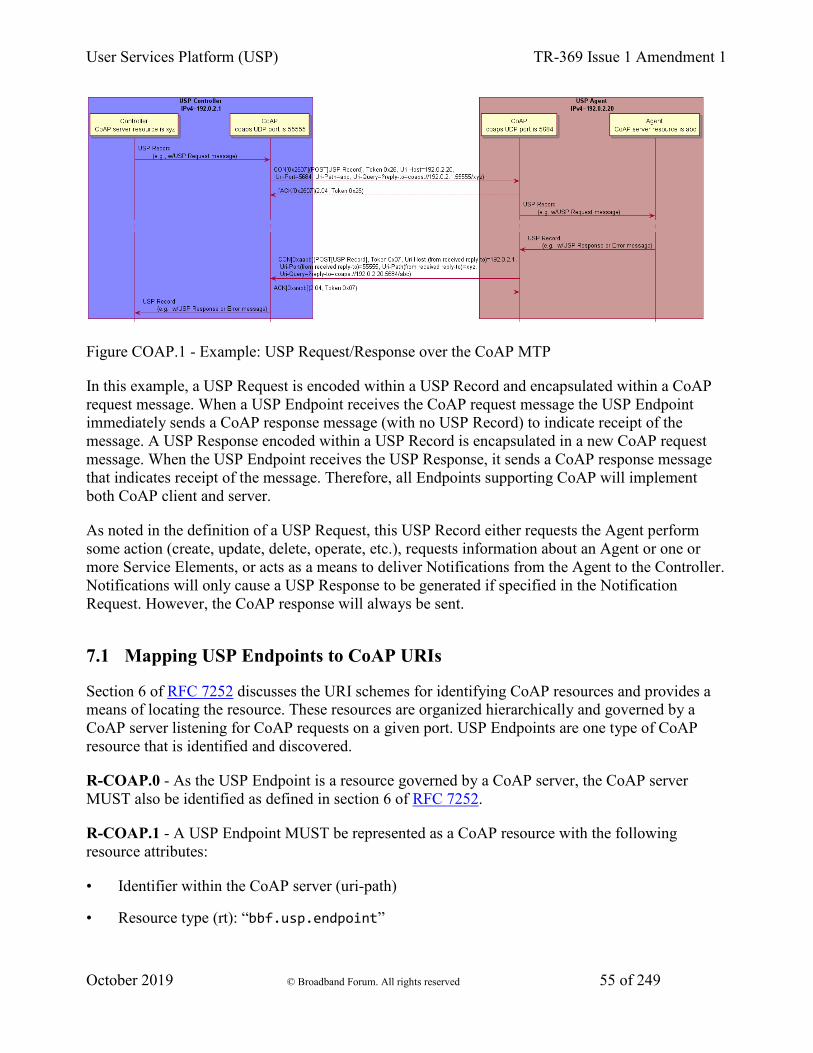
User Services Platform (USP) TR-369 Issue 1 Amendment 1
October 2019 © Broadband Forum. All rights reserved 55 of 249
Figure COAP.1 - Example: USP Request/Response over the CoAP MTP
In this example, a USP Request is encoded within a USP Record and encapsulated within a CoAP request message. When a USP Endpoint receives the CoAP request message the USP Endpoint immediately sends a CoAP response message (with no USP Record) to indicate receipt of the message. A USP Response encoded within a USP Record is encapsulated in a new CoAP request message. When the USP Endpoint receives the USP Response, it sends a CoAP response message that indicates receipt of the message. Therefore, all Endpoints supporting CoAP will implement both CoAP client and server.
As noted in the definition of a USP Request, this USP Record either requests the Agent perform some action (create, update, delete, operate, etc.), requests information about an Agent or one or more Service Elements, or acts as a means to deliver Notifications from the Agent to the Controller. Notifications will only cause a USP Response to be generated if specified in the Notification Request. However, the CoAP response will always be sent.
7.1 Mapping USP Endpoints to CoAP URIs
Section 6 of RFC 7252 discusses the URI schemes for identifying CoAP resources and provides a means of locating the resource. These resources are organized hierarchically and governed by a CoAP server listening for CoAP requests on a given port. USP Endpoints are one type of CoAP resource that is identified and discovered.
R-COAP.0 - As the USP Endpoint is a resource governed by a CoAP server, the CoAP server MUST also be identified as defined in section 6 of RFC 7252.
R-COAP.1 - A USP Endpoint MUST be represented as a CoAP resource with the following resource attributes:
• Identifier within the CoAP server (uri-path)
• Resource type (rt): “bbf.usp.endpoint”
User Services Platform (USP) TR-369 Issue 1 Amendment 1
October 2019 © Broadband Forum. All rights reserved 56 of 249
• Interface (if): “bbf.usp.c” for USP Controller or “bbf.usp.a” for USP Agent
The identifier within the CoAP server is used to deliver messages to the USP Endpoint. When this identifier is used to deliver messages to the USP Endpoint, this identifier is a uri-path that represents the USP Endpoint.
R-COAP.2 - A CoAP request message MUST include a Uri-Query option that supplies the CoAP server URI of the Endpoint that is the source of the CoAP request, formatted as ?reply-to=<coap or coaps uri>. The coap and coaps URIs are defined in sections 6.1 and 6.2 of RFC 7252. The URI MUST NOT include any optional queries at the end.
R-COAP-2a - When a USP Endpoint receives a CoAP request message it MUST use the reply-to Uri-Query option included in the CoAP request as the CoAP URI for the USP Response (if a response is required by the incoming USP Request).
R-COAP.3 - When creating DNS-SD records (see Using DNS), an Endpoint MUST set the DNS-SD TXT record “path” attribute equal to the value of the CoAP server identifier (uri-path).
7.2 Mapping USP Records to CoAP Messages
R-COAP.4 - In order for USP Records to be transferred between a USP Controller and Agent using CoAP, the USP Record MUST be encapsulated within the CoAP message as defined in RFC 7252.
R-COAP.5 – USP Records that exceed the CoAP message size MUST be block encapsulated in accordance with RFC 7959.
USP Records are transferred using the CoAP resource that represents the receiving USP Endpoint using the CoAP POST method as defined in RFC 7252.
R-COAP.6 - The CoAP Content-Format for USP Records MUST be application/octet-stream (ID=42) for protobuf encoding.
7.2.1 Handling CoAP Request Success
R-COAP.7 - Upon successful reception of the CoAP message using POST, the CoAP server MUST respond with a response code of 2.04 (Changed).
7.2.2 Handling CoAP Request Failures
At times CoAP requests fail to complete due to problems in the underlying transport (e.g., timeout) or a failure response code received from the CoAP server due to problems in the CoAP request sent by the CoAP client (4.xx) or problems with the CoAP server implementation (5.xx).
R-COAP.8 - CoAP clients and servers MUST implement the required CoAP response codes defined in section 5.9 of RFC 7252.

User Services Platform (USP) TR-369 Issue 1 Amendment 1
October 2019 © Broadband Forum. All rights reserved 57 of 249
R-COAP.9 - When a CoAP client receives a failure indication (e.g., timeout) from the underlying transport layer, the CoAP client MUST indicate a timeout to the USP Endpoint.
R-COAP.10 - When a CoAP client receives a response code of 4.xx or 5.xx, the CoAP client MUST indicate a CoAP failure to the USP Endpoint.
When a CoAP client sends a CoAP request, the CoAP client can provide incorrect or missing information in the CoAP request. For example, a CoAP client can send a CoAP request with an:
• Invalid CoAP method: The CoAP server responds with a 4.05
• Invalid Content-Format options: The CoAP server responds with a 4.15
• Invalid or not understandable payload: The CoAP server responds with a 4.00
R-COAP.11 - When a CoAP server receives a CoAP request with an invalid CoAP method, the CoAP server MUST respond with a 4.05 response code.
R-COAP.12 - When a CoAP server receives a CoAP request with an invalid CoAP Content-Format option, the CoAP server MUST respond with a 4.15 response code.
R-COAP.13 - When a CoAP server receives a CoAP request and the receiving USP Endpoint cannot interpret or decode the USP Record for processing, the CoAP server MUST respond with a 4.00 response code.
7.3 MTP Message Encryption
CoAP MTP message encryption is provided using DTLS as described in Section 9 of RFC 7252.
In section 9 of RFC 7252, CoAP messages are secured using one of three modes:
• NoSec: DTLS is disabled
• PreSharedKey: DTLS is enabled and the MTP endpoint uses pre-shared keys that are used to validate the identity of CoAP endpoints involved in the message exchange
• RawPublicKey: DTLS is enabled and the MTP endpoint has an asymmetric key pair without a certificate. The MTP endpoint has an identity calculated from the public key and a list of other MTP endpoints to which it can communicate
• Certificate: DTLS is enabled and the MTP endpoint has an asymmetric key pair with an X.509 certificate.
R-COAP.14 - CoAP clients and servers MUST implement the NoSec and Certificate modes of CoAP security as defined in RFC 7252.
While section 9 of RFC 7252 provides guidance on securing CoAP, further guidance related to DTLS implementations for the Internet of Things is provided by RFC 7925.
User Services Platform (USP) TR-369 Issue 1 Amendment 1
October 2019 © Broadband Forum. All rights reserved 58 of 249
R-COAP.15 - CoAP clients and servers MUST implement the mandatory statements of RFC 7925 with the exception that:
• Section 4.4.1 USP Controller certificates can contain domain names with wildcard characters per RFC 6125 guidance.
• Section 4.4.2 Client certificate identifiers do not use EUI-64 identifier but instead use the identifier defined for Client certificates in this Working Text.
• Section 4.4.5 Client Certificate URLs are not required to be implemented.
As USP Endpoints play the role of both CoAP client and server; when the MTP is secured using the Certificate mode of CoAP Security, the USP Endpoint provides a X.509 certificate to the MTP peer.
R-COAP.16 – When the Certificate mode of CoAP is used to secure an MTP, a USP Endpoint MUST provide an X.509 certificate to the MTP peer.
8 STOMP Binding 1. Handling of the STOMP Session
1. Connecting a USP Endpoint to the STOMP Server
2. Handling the STOMP Heart Beat Mechanism
2. Mapping USP Endpoints to STOMP Destinations
1. Subscribing a USP Endpoint to a STOMP Destination
3. Mapping USP Records to STOMP Frames
1. Handling ERROR Frames
2. Handling Other STOMP Frames
4. Discovery Requirements
5. STOMP Server Requirements
6. MTP Message Encryption
The STOMP MTP transfers USP Records between USP endpoints using version 1.2 of the STOMP protocol (further referred to as “STOMP Specification”), or the Simple Text Oriented Message Protocol. Messages that are transferred between STOMP clients utilize a message bus interaction model where the STOMP server is the messaging broker that routes and delivers messages based on the destination included in the STOMP header.
The following figure depicts the transfer of the USP Records between USP Agents and Controllers.
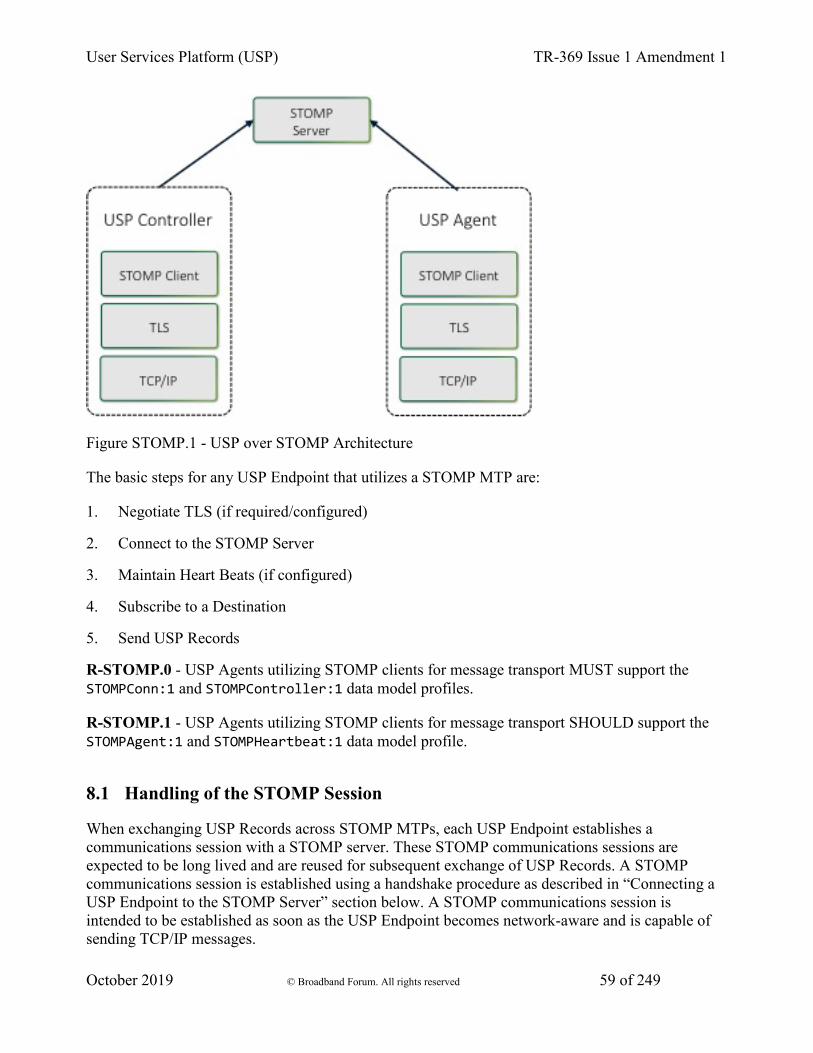
User Services Platform (USP) TR-369 Issue 1 Amendment 1
October 2019 © Broadband Forum. All rights reserved 59 of 249
Figure STOMP.1 - USP over STOMP Architecture
The basic steps for any USP Endpoint that utilizes a STOMP MTP are:
1. Negotiate TLS (if required/configured)
2. Connect to the STOMP Server
3. Maintain Heart Beats (if configured)
4. Subscribe to a Destination
5. Send USP Records
R-STOMP.0 - USP Agents utilizing STOMP clients for message transport MUST support the STOMPConn:1 and STOMPController:1 data model profiles.
R-STOMP.1 - USP Agents utilizing STOMP clients for message transport SHOULD support the STOMPAgent:1 and STOMPHeartbeat:1 data model profile.
8.1 Handling of the STOMP Session
When exchanging USP Records across STOMP MTPs, each USP Endpoint establishes a communications session with a STOMP server. These STOMP communications sessions are expected to be long lived and are reused for subsequent exchange of USP Records. A STOMP communications session is established using a handshake procedure as described in “Connecting a USP Endpoint to the STOMP Server” section below. A STOMP communications session is intended to be established as soon as the USP Endpoint becomes network-aware and is capable of sending TCP/IP messages.
User Services Platform (USP) TR-369 Issue 1 Amendment 1
October 2019 © Broadband Forum. All rights reserved 60 of 249
When a STOMP communications session is no longer necessary, the STOMP connection is closed by the STOMP client, preferably by sending a DISCONNECT frame (see “Handling Other STOMP Frames” section below).
8.1.1 Connecting a USP Endpoint to the STOMP Server
R-STOMP.2 - USP Endpoints utilizing STOMP clients for message transport MUST send a STOMP frame to the STOMP server to initiate the STOMP communications session as defined in the “Connecting” section of the STOMP Specification.
R-STOMP.3 - USP Endpoints that DO NOT utilize client certificate authentication MUST include the login and passcode STOMP headers in the STOMP frame. For a USP Agent, if the .STOMP.Connection.{i}.Username parameter is implemented then its value will be the source for the login STOMP header, and if the .STOMP.Connection.{i}.Password parameter is implemented then its value will be the source for the passcode STOMP header.
R-STOMP.4 - USP Endpoints sending a STOMP frame MUST include (in addition to other mandatory STOMP headers) an endpoint-id STOMP header containing the Endpoint ID of the USP Endpoint sending the frame. NOTE: According to the STOMP Specification, the STOMP frame requires that “C style literal escapes” need to be used to encode any carriage return, line feed, or colon characters that are found within the UTF-8 encoded headers, and R-STOMP.4 requires the Endpoint ID to be included in those headers. Since the Endpoint ID always contains colon characters, those will need to be escaped.
R-STOMP.5 - USP Endpoints sending a STOMP frame MUST include a host STOMP header, if configured to do so. For a USP Agent the value MUST contain the value from the appropriate .STOMP.Connection.{i}.VirtualHost parameter if supported and not empty.
R-STOMP.6 - If the USP Endpoint receives a subscribe-dest STOMP header in the CONNECTED frame, it MUST use the associated value when Subscribing to its destination (see “Subscribing a USP Endpoint to a STOMP Destination” section for more details).
R-STOMP.7 - If the connection to the STOMP server is NOT successful then the USP Endpoint MUST enter a connection retry state. For a USP Agent the retry mechanism is based on the STOMP.Connection.{i}. retry parameters: ServerRetryInitialInterval, ServerRetryIntervalMultiplier, and ServerRetryMaxInterval.
8.1.2 Handling the STOMP Heart Beat Mechanism
The STOMP Heart Beat mechanism can be used to periodically send data between a STOMP client and a STOMP server to ensure that the underlying TCP connection is still available. This is an optional STOMP mechanism and is negotiated when establishing the STOMP connection.
R-STOMP.8 - If the STOMP.Connection instance’s EnableHeartbeats parameter value is True then the USP Agent MUST negotiate the STOMP Heart Beat mechanism within the STOMP frame
User Services Platform (USP) TR-369 Issue 1 Amendment 1
October 2019 © Broadband Forum. All rights reserved 61 of 249
during the process of establishing the STOMP connection as is defined in the “Heart-beating” section of the STOMP Specification.
R-STOMP.9 - If the STOMP.Connection instance’s EnableHeartbeats parameter value is either False or not implemented then the USP Agent MUST either not send the heart-beat STOMP header in the STOMP frame or send “0,0” as the value of the heart-beat STOMP header in the STOMP frame.
R-STOMP.10 - USP Agents negotiating the STOMP Heart Beat mechanism MUST use the STOMP.Connection.{i}.OutgoingHeartbeat and STOMP.Connection.{i}.IncomingHeartbeat parameter values within the heart-beat STOMP header as defined in the “Heart-beating” section of the STOMP Specification.
R-STOMP.11 - USP Agents that have negotiated a STOMP Heart Beat mechanism with a STOMP server MUST adhere to the heart beat values (as defined in the “Heart-beating” section of the STOMP Specification) as returned in the CONNECTED frame.
8.2 Mapping USP Endpoints to STOMP Destinations
USP Agents will have one STOMP destination per STOMP MTP independent of whether those STOMP MTPs use the same STOMP.Connection instance or a different one. The STOMP destination is either configured by the STOMP server via the USP custom subscribe-dest STOMP Header received in the CONNECTED frame (exposed in the Device.LocalAgent.MTP.{i}.STOMP.DestinationFromServer parameter) or taken from the Device.LocalAgent.MTP.{i}.STOMP.Destination parameter if there wasn’t a subscribe-dest STOMP Header received in the CONNECTED frame. The USP custom subscribe-dest STOMP Header is helpful in scenarios where the USP Agent doesn’t have a pre-configured destination as it allows the USP Agent to discover the destination.
A USP Controller will subscribe to a STOMP destination for each STOMP server that it is associated with. The USP Controller’s STOMP destination needs to be known by the USP Agent (this is configured in the Device.LocalAgent.Controller.{i}.MTP.{i}.STOMP.Destination parameter) as it is used when sending a USP Record containing a Notification.
8.2.1 Subscribing a USP Endpoint to a STOMP Destination
R-STOMP.12 - USP Endpoints utilizing STOMP clients for message transport MUST subscribe to their assigned STOMP destination by sending a SUBSCRIBE frame to the STOMP server as defined in the “SUBSCRIBE” section of the STOMP Specification.
R-STOMP.13 - USP Endpoints sending a SUBSCRIBE frame MUST include (in addition to other mandatory STOMP headers) a destination STOMP header containing the STOMP destination associated with the USP Endpoint sending the frame.

User Services Platform (USP) TR-369 Issue 1 Amendment 1
October 2019 © Broadband Forum. All rights reserved 62 of 249
R-STOMP.14 - USP Agents that receive a subscribe-dest STOMP Header in the CONNECTED frame MUST use that STOMP destination in the destination STOMP header when sending a SUBSCRIBE frame.
R-STOMP.15 - USP Agents that have NOT received a subscribe-dest STOMP Header in the CONNECTED frame MUST use the STOMP destination found in the Device.LocalAgent.MTP.{i}.STOMP.Destination parameter in the destination STOMP header when sending a SUBSCRIBE frame.
R-STOMP.16 - USP Agents that have NOT received a subscribe-dest STOMP Header in the CONNECTED frame and do NOT have a value in the Device.LocalAgent.MTP.{i}.STOMP.Destination parameter MUST terminate the STOMP communications session (via the DISCONNECT frame) and consider the MTP disabled.
R-STOMP.17 - USP Endpoints sending a SUBSCRIBE frame MUST use an ack value of “auto”.
8.3 Mapping USP Records to STOMP Frames
A USP Record is sent from a USP Endpoint to a STOMP Server within a SEND frame. The STOMP Server delivers that USP Record to the destination STOMP Endpoint within a MESSAGE frame. When a USP Endpoint responds to the USP request, the USP Endpoint sends the USP Record to the STOMP Server within a SEND frame, and the STOMP Server delivers that USP Record to the destination USP Endpoint within a MESSAGE frame.
R-STOMP.18 - USP Endpoints utilizing STOMP clients for message transport MUST send USP Records in a SEND frame to the STOMP server as defined in the “SEND” section of the STOMP Specification.
R-STOMP.19 - USP Endpoints sending a SEND frame MUST include (in addition to other mandatory STOMP headers) a content-length STOMP header containing the length of the body included in the SEND frame.
R-STOMP.20 - USP Endpoints sending a SEND frame MUST include (in addition to other mandatory STOMP headers) a content-type STOMP header with a value of “application/vnd.bbf.usp.msg”, which signifies that the body included in the SEND frame contains a Protocol Buffer binary encoding message.
R-STOMP.21 - USP Endpoints sending a SEND frame with content-type of application/vnd.bbf.usp.msg MUST include (in addition to other mandatory STOMP headers) a reply-to-dest STOMP header containing the STOMP destination that indicates where the USP Endpoint that receives the USP Record should send any response (if required).
R-STOMP.22 - USP Endpoints sending a SEND frame with content-type of application/vnd.bbf.usp.msg MUST include the Protocol Buffer binary encoding of the USP Record as the body of the SEND frame.

User Services Platform (USP) TR-369 Issue 1 Amendment 1
October 2019 © Broadband Forum. All rights reserved 63 of 249
R-STOMP.23 - When a USP Endpoint receives a MESSAGE frame it MUST use the reply-to-dest included in the STOMP headers as the STOMP destination of the USP response (if a response is required by the incoming USP request).
8.3.1 Handling USP Record errors and ERROR Frames
If a USP Endpoint receives a MESSAGE frame containing a USP Record that cannot be extracted for processing (e.g., text frame instead of a binary frame, malformed USP Record or USP Message, bad encoding), the receiving USP Endpoint will drop the USP Record if the STOMP MESSAGE frame does not have a usp-err-id header or if the receiving Endpoint does not support the application/vnd.bbf.usp.error content-type value. If the receiving Endpoint does support the application/vnd.bbf.usp.error content-type value and the received STOMP MESSAGE frame had a usp-err-id header, the receiving Endpoint will issue a STOMP SEND frame of application/vnd.bbf.usp.error content-type value.
R-STOMP.23a - USP Endpoints MUST support STOMP content-type header value of application/vnd.bbf.usp.error.
R-STOMP.23b - A USP Endpoint MUST include a usp-err-id STOMP header in SEND frames of content-type application/vnd.bbf.usp.msg. The value of this header is: <USP Record to-id > + "/" + <USP Message msg_id>. Since the colon “:” is a reserved character in STOMP headers, all instances of “:” in the USP Record to-id MUST be expressed using an encoding of \c.
R-STOMP.24 - When a USP Endpoint receives a MESSAGE frame containing a USP Record or an encapsulated USP Message within a USP Record that cannot be extracted for processing, the receiving USP Endpoint MUST ignore the USP Record if the received STOMP MESSAGE frame did not include a usp-err-id header.
R-STOMP.24a - When a USP Endpoint receives a MESSAGE frame containing a USP Record or an encapsulated USP Message within a USP Record that cannot be extracted for processing, the receiving USP Endpoint MUST send a STOMP SEND frame with an application/vnd.bbf.usp.error content-type header value if the received STOMP MESSAGE frame included a usp-err-id header.
R-STOMP.24b - A STOMP SEND frame with application/vnd.bbf.usp.error content-type MUST contain the received usp-err-id header, the destination header value set to the received reply-to-dest header, and a message body (formatted using UTF-8 encoding) with the following 2 lines:
• err_code:<numeric code indicating the type of error that caused the overall message to fail>
• err_msg:<additional information about the reason behind the error>
The specific error codes are listed in the MTP Brokered USP Record Errors section.
User Services Platform (USP) TR-369 Issue 1 Amendment 1
October 2019 © Broadband Forum. All rights reserved 64 of 249
The following is an example message. This example uses “^@” to represent the NULL octet that follows a STOMP body.
SEND destination:/usp/the-reply-to-dest content-type:application/vnd.bbf.usp.error usp-err-id:cid\c3AA3F8\cusp-id-42/683 err_code:7100 err_msg:Field n is not recognized.^@
R-STOMP.25 - If an ERROR frame is received by the USP Endpoint, the STOMP server will terminate the connection. In this case the USP Endpoint MUST enter a connection retry state. For a USP Agent the retry mechanism is based on the STOMP.Connection.{i}. retry parameters: ServerRetryInitialInterval, ServerRetryIntervalMultiplier, and ServerRetryMaxInterval.
8.3.2 Handling Other STOMP Frames
R-STOMP.26 - USP Endpoints utilizing STOMP clients for message transport MUST NOT send the transactional STOMP frames including: BEGIN, COMMIT, and ABORT.
R-STOMP.27 - USP Endpoints utilizing STOMP clients for message transport MUST NOT send the acknowledgement STOMP frames including: ACK and NACK.
R-STOMP.28 - USP Endpoints utilizing STOMP clients for message transport MAY send the following STOMP frames when shutting down a STOMP connection: UNSUBSCRIBE (according to the rules defined in the UNSUBSCRIBE section of the STOMP Specification) and DISCONNECT (according to the rules defined in the DISCONNECT section of the STOMP Specification).
R-STOMP.29 - USP Endpoints utilizing STOMP clients for message transport that DID NOT receive a subscribe-dest STOMP Header in the CONNECTED frame when establishing the STOMP communications session MUST update their STOMP subscription when their destination is altered by sending the UNSUBSCRIBE STOMP frame (according to the rules defined in the UNSUBSCRIBE section of the STOMP Specification) and then re-subscribing as detailed in the “Subscribing a USP Endpoint to a STOMP Destination” section.
R-STOMP.30 - USP Endpoints utilizing STOMP clients for message transport MAY receive a RECEIPT frame in which case the STOMP server is acknowledging that the corresponding client frame has been processed by the server.
8.4 Discovery Requirements
The USP discovery section details requirements about the general usage of DNS, mDNS, and DNS-SD records as it pertains to the USP protocol. This section provides further requirements as to how a USP Endpoint advertises discovery information when a STOMP MTP is being utilized.
User Services Platform (USP) TR-369 Issue 1 Amendment 1
October 2019 © Broadband Forum. All rights reserved 65 of 249
R-STOMP.31 - When creating a DNS-SD record, an Endpoint MUST set the DNS-SD “path” attribute equal to the value of the destination that it has subscribed to.
R-STOMP.32 - When creating a DNS-SD record, an Endpoint MUST utilize the STOMP server’s address information in the A and AAAA records instead of the USP Endpoint’s address information.
8.5 STOMP Server Requirements
R-STOMP.33 - A STOMP server implementation MUST adhere to the requirements defined in the STOMP Specification.
R-STOMP.34 - A STOMP server implementation MUST perform authentication of the STOMP client and ensure that a Remote USP Endpoint is only allowed to subscribe to the destination that is associated with the USP Endpoint.
R-STOMP.35 - A STOMP server implementation SHOULD support both Client Certification Authentication and Username/Password Authentication mechanisms.
8.6 MTP Message Encryption
STOMP MTP message encryption is provided using TLS certificates.
R-STOMP.36 - USP Endpoints utilizing STOMP clients for message transport MUST implement TLS 1.2 RFC 5246 or later with backward compatibility to TLS 1.2.
R-STOMP.37 - STOMP server certificates MAY contain domain names and those domain names MAY contain domain names with wildcard characters per RFC 6125 guidance.
9 WebSocket Binding The WebSockets MTP transfers USP Records between USP endpoints using the WebSocket protocol as defined in RFC 6455. Messages that are transferred between WebSocket clients and servers utilize a request/response messaging interaction across an established WebSocket session.
9.1 Mapping USP Endpoints to WebSocket URIs
Section 3 of RFC 6455 discusses the URI schemes for identifying WebSocket origin servers and their target resources. These resources are organized hierarchically and governed by a WebSocket origin server listening for WebSocket messages on a given port. USP Endpoints are one type of WebSocket resource that is identified and discovered.
R-WS.1 - As the USP Endpoint is a resource governed by a WebSocket origin server, the WebSocket server MUST also be identified as defined in section 3 of RFC 6455.
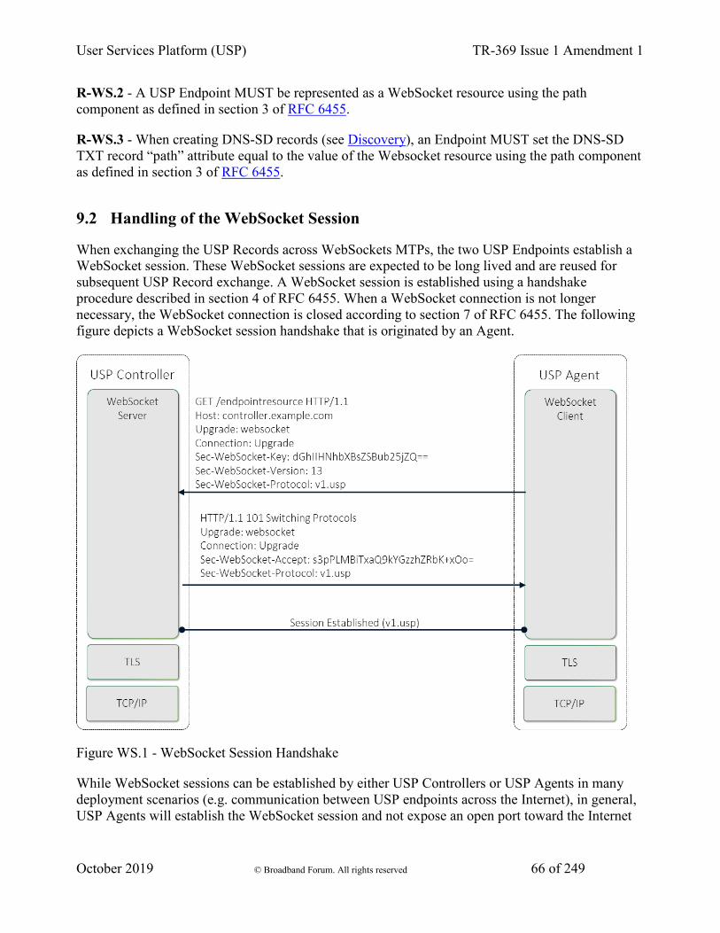
User Services Platform (USP) TR-369 Issue 1 Amendment 1
October 2019 © Broadband Forum. All rights reserved 66 of 249
R-WS.2 - A USP Endpoint MUST be represented as a WebSocket resource using the path component as defined in section 3 of RFC 6455.
R-WS.3 - When creating DNS-SD records (see Discovery), an Endpoint MUST set the DNS-SD TXT record “path” attribute equal to the value of the Websocket resource using the path component as defined in section 3 of RFC 6455.
9.2 Handling of the WebSocket Session
When exchanging the USP Records across WebSockets MTPs, the two USP Endpoints establish a WebSocket session. These WebSocket sessions are expected to be long lived and are reused for subsequent USP Record exchange. A WebSocket session is established using a handshake procedure described in section 4 of RFC 6455. When a WebSocket connection is not longer necessary, the WebSocket connection is closed according to section 7 of RFC 6455. The following figure depicts a WebSocket session handshake that is originated by an Agent.
Figure WS.1 - WebSocket Session Handshake
While WebSocket sessions can be established by either USP Controllers or USP Agents in many deployment scenarios (e.g. communication between USP endpoints across the Internet), in general, USP Agents will establish the WebSocket session and not expose an open port toward the Internet

User Services Platform (USP) TR-369 Issue 1 Amendment 1
October 2019 © Broadband Forum. All rights reserved 67 of 249
for security reasons. Regardless of which entity establishes the WebSocket session, at most one (1) open WebSocket session is utilized between the USP Endpoints.
R-WS.4 - USP Endpoints that exchange USP Records MUST utilize at most one (1) open WebSocket session.
R-WS.5 - USP Agent MUST provide the capability to originate the establishment of a WebSocket session.
R-WS.6 - USP Agent MAY provide the capability to accept the establishment of a WebSocket session from a USP Controller.
R-WS.7 - A USP Endpoint MUST implement the WebSocket handshake protocol to establish a WebSocket connection as defined in section 4 of RFC 6455.
R-WS.8 - A USP Endpoint MUST implement the procedures to close a WebSocket connection as defined in section 7 of RFC 6455.
9.2.1 Mapping USP Records to WebSocket Messages
During the establishment of the WebSocket session, the WebSocket client informs the WebSocket server in the Sec-WebSocket-Protocol header about the type of USP Records that will be exchanged across the established WebSocket connection. For USP Records, the Sec-WebSocket-Protocol header contains the value v1.usp. When presented with a Sec-WebSocket-Protocol header containing v1.usp, the WebSocket Server serving a USP Endpoint returns v1.usp in the response’s Sec-WebSocket-Protocol header. If the WebSocket client doesn’t receive a Sec-WebSocket-Protocol header with a value of v1.usp, the WebSocket client does not establish the WebSocket session.
When a WebSocket connection is being initiated with TLS, no USP Record is sent until the TLS negotiation is complete. The WebSocket server will be unable to identify the Endpoint ID of the client unless it looks inside the certificate. To make it easier for the server to identify the client, the WebSocket Extension bbf-usp-protocol has been registered. The extension parameter of eid is defined for use with this extension. The value of the eid parameter will be the Endpoint ID of the Endpoint sending the WebSocket header.
R-WS.9 - The WebSocket’s handshake Sec-WebSocket-Protocol header for exchange of USP Records using the protocol-buffers encoding mechanism MUST be v1.usp.
R-WS.10 - A WebSocket client MUST include the Sec-WebSocket-Protocol header for exchange of USP Records when initiating a WebSocket session.
R-WS.10a - A WebSocket client MUST include the Sec-WebSocket-Extensions header with bbf-usp-protocol WebSocket Extension and extension parameter eid equal to the client’s Endpoint ID when initiating a WebSocket session.
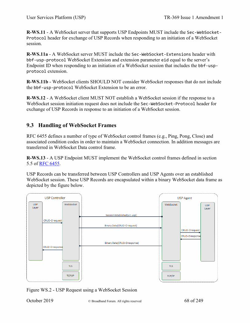
User Services Platform (USP) TR-369 Issue 1 Amendment 1
October 2019 © Broadband Forum. All rights reserved 68 of 249
R-WS.11 - A WebSocket server that supports USP Endpoints MUST include the Sec-WebSocket-Protocol header for exchange of USP Records when responding to an initiation of a WebSocket session.
R-WS.11a - A WebSocket server MUST include the Sec-WebSocket-Extensions header with bbf-usp-protocol WebSocket Extension and extension parameter eid equal to the server’s Endpoint ID when responding to an initiation of a WebSocket session that includes the bbf-usp-protocol extension.
R-WS.11b - WebSocket clients SHOULD NOT consider WebSocket responses that do not include the bbf-usp-protocol WebSocket Extension to be an error.
R-WS.12 - A WebSocket client MUST NOT establish a WebSocket session if the response to a WebSocket session initiation request does not include the Sec-WebSocket-Protocol header for exchange of USP Records in response to an initiation of a WebSocket session.
9.3 Handling of WebSocket Frames
RFC 6455 defines a number of type of WebSocket control frames (e.g., Ping, Pong, Close) and associated condition codes in order to maintain a WebSocket connection. In addition messages are transferred in WebSocket Data control frame.
R-WS.13 - A USP Endpoint MUST implement the WebSocket control frames defined in section 5.5 of RFC 6455.
USP Records can be transferred between USP Controllers and USP Agents over an established WebSocket session. These USP Records are encapsulated within a binary WebSocket data frame as depicted by the figure below.
Figure WS.2 - USP Request using a WebSocket Session
User Services Platform (USP) TR-369 Issue 1 Amendment 1
October 2019 © Broadband Forum. All rights reserved 69 of 249
R-WS.14 - In order for USP Records to be transferred between a USP Controller and Agent using WebSockets MUST be encapsulated within as a binary WebSocket data frame as defined in section 5.6 of RFC 6455.
R-WS.15 - USP Records are transferred between USP Endpoints using message body procedures as defined in section 6 of RFC 6455.
9.3.1 Handling Failures to Deliver USP Records
If a USP Endpoint receives a WebSocket frame containing a USP Record that cannot be extracted for processing (e.g., text frame instead of a binary frame, malformed USP Record or USP Record, bad encoding), the receiving USP Endpoint notifies the originating USP Endpoint that an error occurred by closing the WebSocket connection with a 1003 Status Code with the WebSocket Close frame.
R-WS.16 - A USP Endpoint that receives a WebSocket frame containing a USP Record that cannot be extracted for processing, the receiving USP Endpoint MUST terminate the connection using a WebSocket Close frame with a Status Code of 1003.
9.3.2 Keeping the WebSocket Session Alive
Once a WebSocket session is established, the WebSocket session is expected to remain open for future exchanges of USP Records. The WebSocket protocol uses Ping and Pong control frames as a keep-alive session. Section 5.5 of RFC 6455 discusses the handling of Ping and Pong control frames.
R-WS.17 - A USP Agent MUST implement a WebSocket keep-alive mechanism by periodically sending Ping control frames and respond to Pong control frames as described in section 5.5 of RFC 6455.
R-WS.18 - A USP Agent MUST provide the capability to assign a keep-alive interval in order to send Ping control frames to the remote USP Endpoint.
9.3.3 WebSocket Session Retry
If for any reason a WebSocket Session is closed, the USP Endpoint will attempt to re-establish the WebSocket Session according to its session retry policy. For Controllers, this session retry policy is implementation specific.
R-WS.19 – When retrying to establish a WebSocket Session, the Agent MUST use the following retry algorithm to manage the WebSocket Session establishment procedure:
For Agents, the retry interval range is controlled by two variables (described in the table below): the minimum wait interval and the interval multiplier. The corresponding data model parameter MAY be implemented to allow a USP Controller to change the values of these variables. The factory
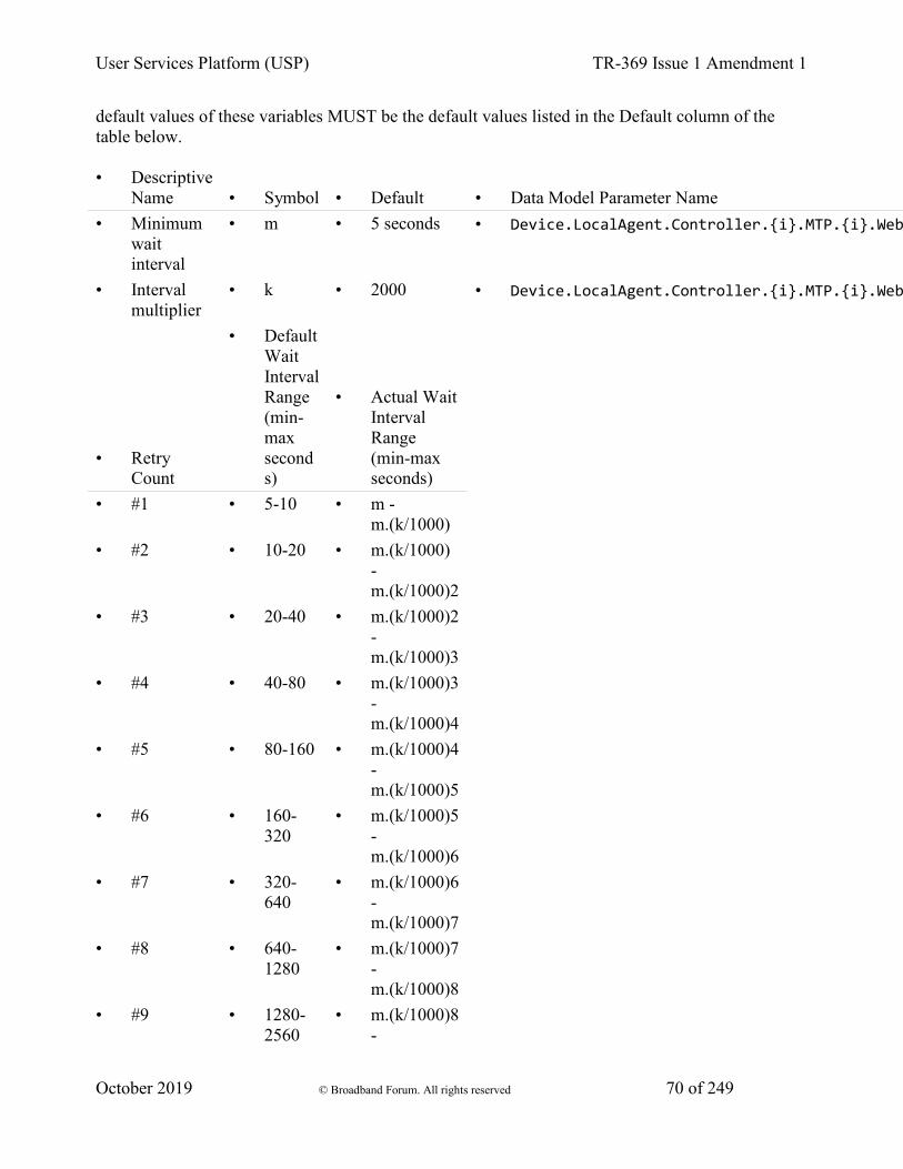
User Services Platform (USP) TR-369 Issue 1 Amendment 1
October 2019 © Broadband Forum. All rights reserved 70 of 249
default values of these variables MUST be the default values listed in the Default column of the table below.
• Descriptive Name • Symbol • Default • Data Model Parameter Name
• Minimum wait interval
• m • 5 seconds • Device.LocalAgent.Controller.{i}.MTP.{i}.Web
• Interval multiplier
• k • 2000 • Device.LocalAgent.Controller.{i}.MTP.{i}.Web
• Retry Count
• Default Wait Interval Range (min-max seconds)
• Actual Wait Interval Range (min-max seconds)
• #1 • 5-10 • m - m.(k/1000)
• #2 • 10-20 • m.(k/1000) - m.(k/1000)2
• #3 • 20-40 • m.(k/1000)2 - m.(k/1000)3
• #4 • 40-80 • m.(k/1000)3 - m.(k/1000)4
• #5 • 80-160 • m.(k/1000)4 - m.(k/1000)5
• #6 • 160-320
• m.(k/1000)5 - m.(k/1000)6
• #7 • 320-640
• m.(k/1000)6 - m.(k/1000)7
• #8 • 640-1280
• m.(k/1000)7 - m.(k/1000)8
• #9 • 1280-2560
• m.(k/1000)8 -
User Services Platform (USP) TR-369 Issue 1 Amendment 1
October 2019 © Broadband Forum. All rights reserved 71 of 249
m.(k/1000)9 • #10 and
subsequent • 2560-
5120 • m.(k/1000)9
- m.(k/1000)10
R-WS.20 – Once a WebSocket session is established between the Agent and the Controller, the Agent MUST reset the WebSocket MTP’s retry count to zero for the next WebSocket Session establishment.
R-WS.21 – If a reboot of the Agent occurs, the Agent MUST reset the WebSocket MTP’s retry count to zero for the next WebSocket Session establishment.
9.4 MTP Message Encryption
WebSocket MTP message encryption is provided using certificates in TLS as described in section 10.5 and section 10.6 of RFC 6455.
R-WS.22 - USP Endpoints utilizing WebSockets clients and servers for message transport MUST implement the Certificate modes of TLS security as defined in sections 10.5 and 10.6 of RFC 6455.
R-WS.23 - USP Endpoints capable of obtaining absolute time SHOULD wait until it has accurate absolute time before contacting the peer USP Endpoint. If a USP Endpoint for any reason is unable to obtain absolute time, it can contact the peer USP Endpoint without waiting for accurate absolute time. If a USP Endpoint chooses to contact the peer USP Endpoint before it has accurate absolute time (or if it does not support absolute time), it MUST ignore those components of the peer USP Endpoint’s WebScoket MTP certificate that involve absolute time, e.g. not-valid-before and not-valid-after certificate restrictions.
R-WS.24 - USP Controller certificates MAY contain domain names with wildcard characters per RFC 6125 guidance.
10 MQTT Binding 1. Connecting a USP Endpoint to the MQTT Server
1. CONNECT Flags and Properties
2. Keep Alive
2. Subscribing to MQTT Topics
3. Sending the USP Record in a PUBLISH Packet Payload
4. Handling Errors
5. Handling Other MQTT Packets
6. Discovery Requirements
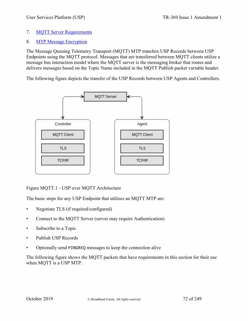
User Services Platform (USP) TR-369 Issue 1 Amendment 1
October 2019 © Broadband Forum. All rights reserved 72 of 249
7. MQTT Server Requirements
8. MTP Message Encryption
The Message Queuing Telemetry Transport (MQTT) MTP transfers USP Records between USP Endpoints using the MQTT protocol. Messages that are transferred between MQTT clients utilize a message bus interaction model where the MQTT server is the messaging broker that routes and delivers messages based on the Topic Name included in the MQTT Publish packet variable header.
The following figure depicts the transfer of the USP Records between USP Agents and Controllers.
Figure MQTT.1 - USP over MQTT Architecture
The basic steps for any USP Endpoint that utilizes an MQTT MTP are:
• Negotiate TLS (if required/configured)
• Connect to the MQTT Server (server may require Authentication)
• Subscribe to a Topic
• Publish USP Records
• Optionally send PINGREQ messages to keep the connection alive
The following figure shows the MQTT packets that have requirements in this section for their use when MQTT is a USP MTP.
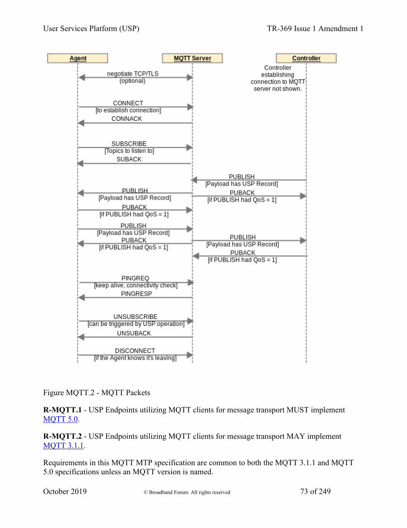
User Services Platform (USP) TR-369 Issue 1 Amendment 1
October 2019 © Broadband Forum. All rights reserved 73 of 249
Figure MQTT.2 - MQTT Packets
R-MQTT.1 - USP Endpoints utilizing MQTT clients for message transport MUST implement MQTT 5.0.
R-MQTT.2 - USP Endpoints utilizing MQTT clients for message transport MAY implement MQTT 3.1.1.
Requirements in this MQTT MTP specification are common to both the MQTT 3.1.1 and MQTT 5.0 specifications unless an MQTT version is named.

User Services Platform (USP) TR-369 Issue 1 Amendment 1
October 2019 © Broadband Forum. All rights reserved 74 of 249
The MQTT specifications are very complete and comprehensive in describing syntax and usage requirements of MQTT packets and behaviors. Therefore, none of those requirements are re-iterated in this specification. This specification only contains requirements unique to use of MQTT as a USP MTP. The above two requirements for compliance with the MQTT specifications are critical in developing an implementation compliant with this MQTT Binding specification. Wherever an MQTT packet or other functionality is mentioned in the requirements in this MQTT Binding specification, the requirement for compliance with the MQTT specification (R-MQTT.1 and R-MQTT.2) apply.
R-MQTT.3 - USP Agents utilizing MQTT clients for message transport MUST support MQTT over TCP transport protocol.
The MQTT specification also describes how MQTT can run over WebSockets. Deployments can choose to use MQTT over WebSockets, if they use MQTT clients and servers with support for this option. The TCP option is required to ensure interoperability.
R-MQTT.4 - USP Agents utilizing MQTT clients for message transport MUST support the MQTTClientCon:1, MQTTClientSubscribe:1, MQTTAgent:1, and MQTTController:1 data model profiles.
R-MQTT.5 - USP Agents utilizing MQTT clients for message transport SHOULD support the MQTTClientExtended:1 data model profile.
10.1 Connecting a USP Endpoint to the MQTT Server
When exchanging USP Records across MQTT MTPs, each USP Endpoint establishes a communications session with an MQTT server. These MQTT communications sessions are expected to be long-lived and are re-used for subsequent exchange of USP Records. An MQTT communications session is established using the procedure in this section. An MQTT communications session is intended to be established as soon as the USP Endpoint becomes network-aware and can send TCP/IP messages.
When an MQTT communications session is no longer necessary or expires (see “Keep Alive” section below), the MQTT connection is closed by the MQTT client, preferably by sending a DISCONNECT packet (see Handling Other MQTT Packets section below).
R-MQTT-1 and R-MQTT-2 require that all MQTT capabilities referenced in this section and its sub-sections are compliant with the MQTT specifications. Reading the MQTT specification is highly recommended to ensure the correct syntax and usage of MQTT packets and properties (CONNECT, CONNACK, User Name, Password, ClientId, User Property, Keep Alive, PINGREQ, PINGRESP, etc.).
R-MQTT.6 - USP Endpoints utilizing MQTT clients for message transport MUST send a CONNECT packet to the MQTT server to initiate the MQTT communications session.
R-MQTT.7 - USP Endpoints with a configured MQTT User Name and Password for use with this MQTT server MUST include these in the MQTT CONNECT packet. The
User Services Platform (USP) TR-369 Issue 1 Amendment 1
October 2019 © Broadband Forum. All rights reserved 75 of 249
.MQTT.Client.{i}.Username and .MQTT.Client.{i}.Password parameters values (associated with this MQTT server) will be used for User Name and Password.
R-MQTT.8 - USP Endpoints MUST set the value of the CONNECT packet Client Identifier (ClientId) as follows:
• If a non-empty, non-null ClientId value exists for use with this MQTT server, this MUST be used. The data model parameter for the ClientId is .MQTT.Client.{i}.ClientID.
• If an MQTT 5.0 client has no configured ClientId (null or empty string) the USP Endpoint MUST send an empty string in the Client Identifier property.
• If an MQTT 3.1.1 client has no configured ClientId, the USP Endpoint SHOULD attempt to use its USP Endpoint ID as the ClientId.
R-MQTT.9 - An MQTT 5.0 client MUST save (in the .MQTT.Client.{i}.ClientID parameter) an Assigned Client Identifier included in a CONNACK packet as its configured ClientId for future use.
R-MQTT.10 - If the connection to the MQTT server is NOT successful then the USP Endpoint MUST enter a connection retry state. For a USP Agent the retry mechanism is based on the MQTT.Client.{i}. retry parameters: ConnectRetryTime, ConnectRetryIntervalMultiplier, and ConnectRetryMaxInterval.
R-MQTT.11 - Once a USP Endpoint has successfully connected to an MQTT server, it MUST use the same ClientId for all subsequent connections with that server.
10.1.1 CONNECT Flags and Properties
The MQTT CONNECT packet has a number of flags and properties that can be set. The User Name and Password flags are set to 1 if these parameters are included. The use of the Will Retain, Will QoS, and Will Flag are left up to the deployment. They are not needed in order to use MQTT as a USP MTP and can be “0” if there is no deployment-specified need for them. The Clean Start flag can also be used according to deployment-specified needs. Configured values for these flags can be provided through the related .MQTT.Client.{i}. parameters.
MQTT 3.1.1 does not provide a simple mechanism for a USP MQTT client to provide its Endpoint ID to the MQTT server. But the server does have other options, such as:
1. Support Endpoint ID as ClientId.
2. Get Endpoint ID from client TLS certificate.
MQTT 3.1.1 also does not provide a mechanism for the MQTT server to tell a client what Topic other Endpoints should use to send it a message (the “reply to” Topic). This information would need to be pre-configured or provided in some manner not specified here.
MQTT 5.0 includes additional properties that deployments can choose to use.
User Services Platform (USP) TR-369 Issue 1 Amendment 1
October 2019 © Broadband Forum. All rights reserved 76 of 249
R-MQTT.12 - An MQTT 5.0 USP Endpoint MUST support setting the Request Response Information property to 1, and MUST support receiving the corresponding Response Information in the CONNACK packet.
The Response Information property is used by an MQTT 5.0 client as the Response Topic (which is the MQTT 5.0 PUBLISH packet property identifying the Topic to send a USP response to). The Response Information property requirements for use of the received Response Information are below in the section Sending the USP Record in a PUBLISH Packet Payload. Ensuring the client is subscribed to this Topic or a Topic Filter that includes this Topic is described in Subscribing to MQTT Topics.
R-MQTT.13 - An MQTT 5.0 USP Endpoint MUST include a User Property name-value pair in the CONNECT packet with name of “usp-endpoint-id” and value of this Endpoint’s USP Endpoint ID.
10.1.2 Keep Alive
The MQTT Keep Alive mechanism has several components:
• The CONNECT packet Keep Alive field tells the server to disconnect the client if the server does not receive a packet from the client before the Keep Alive time (in seconds) has elapsed since the prior received packet.
• The MQTT 5.0 CONNACK packet Keep Alive field allows the server to inform the client the maximum interval the server will allow to elapse between received packets before it disconnects the client due to inactivity.
• PINGREQ and PINGRESP packets can be used to keep the connection up if the timer is nearing expiry and there is no need for another type of message. PINGREQ can also be used by the client at any time to check on the status of the connection.
The client can indicate the Server is not required to disconnect the Client on the grounds of inactivity by setting the CONNECT Keep Alive to zero (0). Note that WebSockets mechanisms can be used to keep the connection alive if MQTT is being run over WebSockets. Also note the server is allowed to disconnect the client at any time, regardless of Keep Alive value.
R-MQTT.14 - USP Endpoints with a configured Keep Alive value MUST include this in the MQTT CONNECT packet. The .MQTT.Client.{i}. KeepAliveTime parameter value (associated with this MQTT server) will be used for the Keep Alive value.
Use of PINGREQ and PINGRESP for keeping sessions alive (or determining session aliveness) is as described in the MQTT specification. No additional requirements are provided for use of these packets in a USP context.
10.2 Subscribing to MQTT Topics
User Services Platform (USP) TR-369 Issue 1 Amendment 1
October 2019 © Broadband Forum. All rights reserved 77 of 249
The SUBSCRIBE packet is sent by the MQTT client to subscribe to one or more Topics or Topic Filters. These are needed to allow the MQTT client to receive application messages. The MQTT client will receive all application messages published by other clients that are sent to a Topic that matches (either exactly or within a wildcarded Topic Filter) a subscribed-to Topic or Topic Filter. The MQTT server indicates in the SUBACK response packet whether the client has succeeded or failed to subscribe to each Topic or Topic Filter sent in the SUBSCRIBE packet.
USP Endpoints can be configured with one or more specific MQTT Topics or Topic Filters to subscribe to for each MQTT server they are associated with. In MQTT 5.0, a CONNACK User Property named “subscribe-topic” can be used to provide the client with Topic or Topic Filter values for the client to subscribe to. There is no similar capability in MQTT 3.1.1. This means configuration or some out-of-band mechanism are the only means of supplying subscription Topics or Topic Filters to an MQTT 3.1.1 client. An Agent will need to be configured with a Controller’s MQTT Topic (the Device.LocalAgent.Controller.{i}.MTP.{i}.MQTT.Topic parameter is used to configure this), to send a Notification to that Controller.
R-MQTT-1 and R-MQTT-2 require that all MQTT capabilities referenced in this section and its sub-sections are compliant with the MQTT specifications. Reading the MQTT specification is highly recommended to ensure the correct syntax and usage of MQTT packets and properties (SUBSCRIBE, Topic Filter, QoS 0, QoS 1, QoS 2, etc.).
R-MQTT.15 - USP Endpoints that successfully connect to an MQTT server MUST send a SUBSCRIBE packet with all Topic Filters identified in the following list:
• All configured Topic Filter values for use with this MQTT server MUST be included in a SUBSCRIBE packet. For a USP Agent, the .MQTT.Client.{i}.Subscription.{i}. table can be used to configure Topic Filter values.
• If an MQTT 5.0 USP Endpoint received one or more User Property in the CONNACK packet where the name of the name-value pair is “subscribe-topic”, the USP Endpoint MUST include the value of all such name-value pairs in its SUBSCRIBE packet as a Topic Filter.
• If an MQTT 5.0 Endpoint received a Response Information property in the CONNACK packet, and the topic from that Response Information property is not included (directly or as a subset of a Topic Filter) among the Topic Filters of the previous 2 bullets, the Endpoint MUST include the value of the Response Information property in its SUBSCRIBE packet.
• If an Endpoint has a ResponseTopicConfigured value and did not receive a Response Information property in the CONNACK packet, and the topic in the ResponseTopicConfigured parameter is not included (directly or as a subset of a Topic Filter) among the Topic Filters of the first 2 bullets, the Endpoint MUST include the value of the ResponseTopicConfigured in its SUBSCRIBE packet.
R-MQTT.16 - USP Agents that have NOT received a “subscribe-topic” User Property in the CONNACK and do NOT have a configured Topic Filter (Device.MQTT.Client.{i}.Subscription.{i}.Topic parameter for this Client instance in the data model) MUST terminate the MQTT communications session (via the DISCONNECT packet) and consider the MTP disabled.
User Services Platform (USP) TR-369 Issue 1 Amendment 1
October 2019 © Broadband Forum. All rights reserved 78 of 249
R-MQTT.17 - If a USP Endpoint does not successfully subscribe to at least one Topic, it MUST NOT publish a packet with a USP Record in its Application Message, and MUST disconnect from the MQTT server.
For each Topic listed in a SUBSCRIBE packet, the client will also provide a desired QoS level. See the MQTT specification (MQTT 3.1.1 or MQTT 5.0, Section 4.3) for description of the three QoS levels (QoS 0, QoS 1, QoS 2). The usefulness of these QoS levels in the context of USP depends on the particulars of the MQTT deployment. It is therefore up to the implementer / deployer to decide which QoS setting to use. In order to ensure deployments have the ability to use at least QoS 1, MQTT clients and servers are required to implement at least QoS 1 (see requirements in Sending the USP Record in a PUBLISH Packet Payload and MQTT Server Requirements.
10.3 Sending the USP Record in a PUBLISH Packet Payload
A USP Record is sent from a USP Endpoint to an MQTT Server within a PUBLISH packet payload. The MQTT Server delivers that PUBLISH packet to the destination MQTT client USP Endpoint. This is true of all USP Message types.
R-MQTT-1 and R-MQTT-2 require that all MQTT capabilities referenced in this section and its sub-sections are compliant with the MQTT specifications. Reading the MQTT specification is highly recommended to ensure the correct syntax and usage of MQTT packets and properties (PUBLISH, Content Type, Response Topic, etc.).
R-MQTT.18 - USP Endpoints utilizing MQTT clients for message transport MUST send the USP Record in the payload of a PUBLISH packet.
R-MQTT.19 - USP Endpoints MUST send USP Records using the Protocol Buffer binary encoding of the USP Record.
R-MQTT.20 - USP Endpoints utilizing MQTT clients for message transport MUST support MQTT QoS 0 and QoS 1.
The USP Controller’s MQTT Topic needs to be known by any USP Agent expected to send a Notify message to the Controller.
The USP Agent will also need to know an exact Topic where it can be reached (and not just a Topic Filter) in order to provide a Controller with the Agent’s “reply to” Topic.
R-MQTT.21 - An MQTT 5.0 USP Endpoint that receives Response Information in the CONNACK packet MUST use this as its “reply to” Topic.
R-MQTT.22 - USP Endpoints MUST include a “reply to” Topic in all PUBLISH packets transporting USP Records.
R-MQTT.23 - USP Endpoints using MQTT 5.0 MUST include their “reply to” Topic in the PUBLISH Response Topic property.

User Services Platform (USP) TR-369 Issue 1 Amendment 1
October 2019 © Broadband Forum. All rights reserved 79 of 249
R-MQTT.24 - USP Endpoints using MQTT 3.1.1 MUST include their “reply to” Topic after a forward slash “/reply-to=” at the end of the PUBLISH Topic Name, with any “/” character in the Topic replaced by “%2F”.
For example, if a Controller’s “reply to” Topic is “usp/controllers/oui:00256D:my-unique-bbf-id-42”, and it is sending to an Agent whose Topic is “usp/agents/cid:3AA3F8:my-unique-usp-id-42”, the PUBLISH Topic Name for a USP Controller using an MQTT 3.1.1 client will be “usp/agents/cid:3AA3F8:my-unique-usp-id-42/reply-to= usp%2Fcontrollers%2Foui:00256D:my-unique-bbf-id-42”.
USP Endpoints that need to send a response to a received USP Record will need to determine the Topic Name to use in the responding PUBLISH packet.
R-MQTT.25 - USP Endpoints using MQTT 3.1.1 MUST interpret the portion of the received PUBLISH Topic Name following the last forward slash “/reply-to=” as the response Topic Name. Any instance of “%2F” in this received string MUST be replaced with “/”.
R-MQTT.26 - USP Endpoints using MQTT 5.0 MUST use the received PUBLISH Response Topic property as the response Topic Name.
R-MQTT.27 - USP Endpoints sending a USP Record using MQTT 5.0 MUST have “application/vnd.bbf.usp.msg” in the Content Type property.
MQTT clients using MQTT 3.1.1 will need to know to pass the payload to the USP Agent for handling. There is no indication in MQTT 3.1.1 of the payload application or encoding. an MQTT 3.1.1 deployment could choose to dedicate the MQTT connection to USP, or put something in the syntax of PUBLISH packet Topic Names that would indicate the payload is a USP Record.
10.4 Handling Errors
The MQTT specification requires servers and clients to disconnect if there is a violation at the MQTT protocol layer.
If an MQTT 5.0 USP Endpoint receives a PUBLISH packet containing a USP Record that cannot be extracted for processing (e.g., text frame instead of a binary frame, malformed USP Record or USP Message, bad encoding), it is required to send an error message (described below). An MQTT 3.1.1 receiving USP Endpoint will silently drop the unprocessed USP Record.
R-MQTT-1 and R-MQTT-2 require that all MQTT capabilities referenced in this section and its sub-sections are compliant with the MQTT specifications. Reading the MQTT specification is highly recommended to ensure the correct syntax and usage of MQTT packets and properties (PUBLISH, PUBACK, etc.).
R-MQTT.28 - MQTT 5.0 Endpoints MUST support PUBLISH Content Type value of application/vnd.bbf.usp.error.
User Services Platform (USP) TR-369 Issue 1 Amendment 1
October 2019 © Broadband Forum. All rights reserved 80 of 249
R-MQTT.29 - MQTT 5.0 Endpoints MUST include a usp-err-id MQTT User Property in PUBLISH packets of content-type “application/vnd.bbf.usp.msg”. The value of this header is: <USP Record to-id> + “/” + <USP Message msg_id>.
R-MQTT.30 - When an MQTT 3.1.1 USP Endpoint receives a PUBLISH packet containing a USP Record or an encapsulated USP Message within a USP Record that cannot be extracted for processing, the receiving USP Endpoint MUST silently drop the USP Record.
R-MQTT.31 - When an MQTT 5.0 USP Endpoint receives a PUBLISH packet containing a USP Record or an encapsulated USP Message within a USP Record that cannot be extracted for processing, the receiving USP Endpoint MUST send a PUBLISH packet with Content Type application/vnd.bbf.usp.error, a User Property set to the received usp-err-id User Property, the Topic Name set to the received Response Topic, and a PUBLISH Payload (formatted using UTF-8 encoding) with the following 2 lines:
• err_code:<numeric code indicating the type of error that caused the overall message to fail>
• err_msg:<additional information about the reason behind the error>
The specific error codes are listed in the MTP Brokered USP Record Errors section.
MQTT 5.0 includes a Reason Code that is used to respond to PUBLISH packets when QoS 1 or QoS 2 is used.
R-MQTT.32 - When a USP Endpoint using MQTT 5.0 receives a PUBLISH packet with QoS 1 or QoS 2 containing a USP Record or an encapsulated USP Message within a USP Record that cannot be extracted for processing, the receiving USP Endpoint MUST include Reason Code 153 (0x99) identifying “Payload format invalid” in any PUBACK or PUBREC packet.
Note these packets will be received by the MQTT server and will not be forwarded to the USP Endpoint that originally sent the USP Record.
R-MQTT.33 - If the MQTT server terminates the connection, the USP Endpoint MUST enter a connection retry state. For a USP Agent the retry mechanism is based on the MQTT.Client.{i}. ConnectRetryTime parameter.
10.5 Handling Other MQTT Packets
Use of PUBREL, and PUBCOMP depends on the QoS level being used for the subscribed Topic. No additional requirements are provided for use of these packets in a USP context.
Use of PINGREQ and PINGRESP for keeping sessions alive (or determining session aliveness) is as described in the MQTT specification. No additional requirements are provided for use of these packets in a USP context.
Use of UNSUBSCRIBE and UNSUBACK is as described in the MQTT specification. If an Agent’s configured Topics are disabled by a Controller (by setting
User Services Platform (USP) TR-369 Issue 1 Amendment 1
October 2019 © Broadband Forum. All rights reserved 81 of 249
Device.MQTT.Client.{i}.Subscription.{i}.Enable to “false”), UNSUBSCRIBE is used to unsubscribe from them.
R-MQTT.34 - USP Endpoints utilizing MQTT clients for message transport SHOULD send an UNSUBSCRIBE packet when a subscribed Topic or Topic Filter is no longer indicated but the MQTT connection is expected to stay up.
R-MQTT-1 and R-MQTT-2 require that all MQTT capabilities referenced in this section and its sub-sections are compliant with the MQTT specifications. Reading the MQTT specification is highly recommended to ensure the correct syntax and usage of MQTT packets and properties (DISCONNECT, etc.).
R-MQTT.35 - USP Endpoints utilizing MQTT clients for message transport SHOULD send a DISCONNECT packet when shutting down an MQTT connection.
MQTT 5.0 specifies the AUTH packet to use for extended authentication. Implementations can make use of extended authentication but should only do so if they are sure that all clients and servers will support the same authentication mechanisms.
10.6 Discovery Requirements
The USP discovery section details requirements about the general usage of DNS, mDNS, and DNS-SD records as it pertains to the USP protocol. This section provides further requirements as to how a USP Endpoint advertises discovery information when an MQTT MTP is being utilized.
R-MQTT.36 - When creating a DNS-SD record, an Agent MUST set the DNS-SD “path” attribute equal to the value of its “reply to” Topic.
R-MQTT.37 - When creating a DNS-SD record, a Controller MUST set the DNS-SD “path” attribute equal to a value that is included among the Controller’s subscribed Topics and Topic Filters.
R-MQTT.38 - When creating a DNS-SD record, an Endpoint MUST utilize the MQTT server’s address information in the A and AAAA records instead of the USP Endpoint’s address information.
10.7 MQTT Server Requirements
R-MQTT.39 - MQTT servers MUST implement MQTT 5.0.
R-MQTT.40 - MQTT servers SHOULD implement MQTT 3.1.1.
R-MQTT.41 - MQTT servers MUST implement MQTT over TCP transport protocol.
R-MQTT.42 - An MQTT server MUST support authentication of the MQTT client through at least one of the mechanisms described in Section 5.4.1 of the MQTT specification, and support an
User Services Platform (USP) TR-369 Issue 1 Amendment 1
October 2019 © Broadband Forum. All rights reserved 82 of 249
Access Control List mechanism that can restrict the topics an authenticated MQTT client can subscribe or publish to.
R-MQTT.43 - An MQTT server SHOULD support both Client Certification Authentication and User Name / Password Authentication mechanisms.
R-MQTT.44 - An MQTT server SHOULD support sending Topic or Topic Filter values in a “subscribe-topic” User Property in the CONNECT packet.
R-MQTT.45 - If an MQTT server supports subscriptions from unconfigured Agents, it MUST support wildcarded Topic Filters.
This will allow support for Agents that try to subscribe to “+/<Endpoint ID>/#” and “+/+/<Endpoint ID>/#” Topic Filters.
R-MQTT.46 - An MQTT server MUST support at least MQTT QoS 1 level.
R-MQTT.47 - An MQTT server SHOULD support a ClientId value that is a USP Endpoint ID. This includes supporting all Endpoint ID characters (includes “-”, “.”, “_”, “%”, and “:”) and at least 64 characters length.
10.8 MTP Message Encryption
MQTT MTP message encryption is provided using TLS certificates.
R-MQTT.48 - USP Endpoints utilizing MQTT clients for message transport MUST implement TLS 1.2 RFC 5246 or later with backward compatibility to TLS 1.2.
R-MQTT.49 - MQTT server certificates MAY contain domain names and those domain names MAY contain domain names with wildcard characters per RFC 6125 guidance.
11 Message Encoding USP requires a mechanism to serialize data to be sent over a message transfer protocol. The description of each individual message and the USP Record encoding scheme is covered in a section of this document and/or in the referenced specification. This version of the specification includes support for:
• Protocol Buffers Version 3
R-ENC.0 - An implementation using protocol buffers encoding to encode USP Messages (Requests, Responses, and Errors) MUST conform to the schema defined in usp-msg.proto.
R-ENC.1 - An implementation using protocol buffers encoding to encode USP Records MUST conform to the schema defined in usp-record.proto.
User Services Platform (USP) TR-369 Issue 1 Amendment 1
October 2019 © Broadband Forum. All rights reserved 83 of 249
Protocol Buffers Version 3 uses a set of enumerated elements to coordinate encoding and decoding during transmission. It is intended that these remain backwards compatible, but new versions of the schema may contain new enumerated elements.
R-ENC.2 - If an Endpoint receives a USP payload containing an unknown enumeration value for a known field, the Endpoint MUST report the failure to the receiving MTP to indicate a “bad request” and do no further processing of the USP Record or USP Message.
Protocol Buffers uses a datatype called oneof. This means that the element contains elements of one or more varying types.
R-ENC.3 - USP Records and USP Messages that contain an element of type oneof MUST include 1 and only 1 instance of the element, which MUST contain one of the possible elements.
R-ENC.4 - A USP Record that violates R-ENC.3 MUST be discarded.
R-ENC.5 - A USP Message that violates R-ENC.3 SHOULD return an error of type 7004 (Invalid Arguments).
12 End to End Message Exchange USP Messages are exchanged between Controllers and Agents. In some deployment scenarios, the Controller and Agent have a direct connection. In other deployment scenarios, the messages exchanged by the Controller and Agent traverse multiple intermediate MTP Proxies. The latter deployment scenario typically occurs when the Agent or Controller is deployed outside the proximal or Local Area Network. In both types of scenarios, the End-to-End (E2E) message exchange capabilities of USP permit the:
• Exchange of USP Records within an E2E Session Context that allows for:
– Integrity protection for non-payload fields
– Protected and unprotected payloads
– Segmentation and reassembly of E2E Messages that would be too large to transfer through the intermediate MTP Proxies.
• Exchange of USP Records without an E2E Session Context that allows for:
– Integrity protection for non-payload fields
– Unprotected payloads or protected payloads where the payload protection security mechanism doesn’t require a concept of a session (e.g., COSE)
Protected payloads provide a secure message exchange (confidentiality, integrity and identity authentication) through exchange of USP Messages that are secured by the originating and receiving USP Endpoints.

User Services Platform (USP) TR-369 Issue 1 Amendment 1
October 2019 © Broadband Forum. All rights reserved 84 of 249
Note - the requirements below reference Objects and Parameters used to manage the E2E Session. These are specified in the Device:2 Data Model for USP Agents.
12.1 USP Record Encapsulation
The USP Record Message is defined as the Message Transfer Protocol (MTP) payload, encapsulating a sequence of datagrams that comprise the USP Message as well as providing additional metadata needed for integrity protection, payload protection and delivery of fragmented USP Messages. Additional metadata fields are used to identify the E2E session context, determine the state of the segmentation and reassembly function, acknowledge received datagrams, request retransmissions, and determine the type of encoding and security mechanism used to encode the USP Message.
Following are the fields contained within a USP Record. When not explicitly set or included in the Record, the fields have a default value based on the type of field. For strings, the default value is an empty byte string. For numbers (uint64) and enumerations, the default value is 0. For repeated bytes, the default value is an empty byte string. The term “Optional” means it is not necessary to include the field in a sent Record. The receiving Endpoint will use default values for fields not included in a received Record. “Required” fields are always included. A Record without a “Required” field will fail to be processed by a receiving Endpoint. “Repeated” fields can be included any number of times, including zero.
12.1.1 Record Definition
Note: This version of the specification defines Record in Protocol Buffers v3 (see encoding). This part of the specification may change to a more generic description (normative and non-normative) if further encodings are specified in future versions.
string version
Required. Version (Major.Minor) of the USP Protocol (i.e., “1.0” or “1.1”).
string to_id
Required. Receiving/Target USP Endpoint Identifier.
R-E2E.1 - A receiving USP Endpoint MUST ignore any Record that does not contain its own Endpoint Identifier as the to_id.
string from_id
Required. Originating/Source USP Endpoint Identifier.
enum PayloadSecurity payload_security
User Services Platform (USP) TR-369 Issue 1 Amendment 1
October 2019 © Broadband Forum. All rights reserved 85 of 249
Optional. An enumeration of type PayloadSecurity. When the payload is present, this indicates the protocol or mechanism used to secure the payload (if any) of the USP Message. The value of TLS12 means TLS 1.2 or later (with backward compatibility to TLS 1.2) will be used to secure the payload (see “TLS Payload Encapsulation” section).
Valid values are:
PLAINTEXT (0) TLS12 (1)
bytes mac_signature
Optional. When integrity protection of non-payload fields is performed, this is the message authentication code or signature used to ensure the integrity of the non-payload fields of the USP Record.
bytes sender_cert
Optional. The PEM encoded certificate of the sending USP Endpoint used to provide the signature in the mac_signature field, when integrity protection is used and the payload security mechanism doesn’t provide the mechanism to generate the mac_signature.
oneof record_type
Required. This field contains one of the types given below:
NoSessionContextRecord no_session_context
SessionContextRecord session_context
12.1.1.1 NoSessionContextRecord fields
The following describe the fields included if record_type is no_session_context.
bytes payload
Required. The USP Message.
12.1.1.2 SessionContextRecord fields
The following describe the fields included if record_type is session_context.
uint64 session_id
Required. This field is the Session Context identifier.
uint64 sequence_id

User Services Platform (USP) TR-369 Issue 1 Amendment 1
October 2019 © Broadband Forum. All rights reserved 86 of 249
Required. Datagram sequence identifier. Used only for exchange of USP Records with an E2E Session Context. The field is initialized to 1 when starting a new Session Context and incremented after each sent USP Record.
Note: Endpoints maintain independent values for received and sent sequence_id for a Session Context, based respectively on the number of received and sent records.
uint64 expected_id
Required. This field contains the next sequence_id the sender is expecting to receive, which implicitly acknowledges to the recipient all transmitted datagrams less than expected_id. Used only for exchange of USP Records with an E2E Session Context.
uint64 retransmit_id
Optional. Used to request a USP Record retransmission by a USP Endpoint to request a missing USP Record using the missing USP Record’s anticipated sequence_id. Used only for exchange of USP Records with an E2E Session Context.
R-E2E.2 – A USP Record with record_type = session_context MUST contain either a payload, a retransmit_id, or both fields.
enum PayloadSARState payload_sar_state
Optional. An enumeration of type PayloadSARState. When payload is present, indicates the segmentation and reassembly state represented by the USP Record. Valid values are:
NONE (0) BEGIN (1) INPROCESS (2) COMPLETE (3)
enum PayloadSARState payloadrec_sar_state
Optional. An enumeration of type PayloadSARState. When payload segmentation is being performed, indicates the segmentation and reassembly state represented by an instance of the payload datagram. If payload_sar_state = 0 (or is not included or not set), then payloadrec_sar_state will be 0 (or not included or not set). Valid values are:
NONE (0) BEGIN (1) INPROCESS (2) COMPLETE (3)
repeated bytes payload
Optional. This repeated field is a sequence of zero, one, or multiple datagrams. It contains the Message, in either PLAINTEXT or encrypted format. When using TLS12 payload security there will
User Services Platform (USP) TR-369 Issue 1 Amendment 1
October 2019 © Broadband Forum. All rights reserved 87 of 249
be a payload field for each encrypted TLS record. When using PLAINTEXT payload security there will be a single payload field for any Message being sent.
12.2 Exchange of USP Records within an E2E Session Context
When exchanging USP Records within an E2E Session Context, record_type of session_context is used, and all required parameters for record_type of session_context are supplied.
12.2.1 Establishing an E2E Session Context
For the exchange of USP Records within an E2E Session Context to happen between two USP Endpoints, an E2E Session Context (Session Context) is established between the participating USP Endpoints. The Session Context is uniquely identified within the USP Endpoint by the combination of the Session Identifier and remote USP Endpoint’s Identifier.
In USP, either a Controller or an Agent can begin the process of establishing a Session Context. This is done by the Controller or Agent sending a USP Record with a session_id field that is not currently associated with the Agent/Controller combination and a sequence_id field value of 1.
R-E2E.3 – Session Context identifiers MUST be generated by the USP Endpoint that originates the session such that it is greater than 1 and scoped to the remote USP Endpoint.
When a Session Context had been previously established between an Agent and Controller and the remote USP Endpoint receives a USP Record with a different session_id field, the remote USP Endpoint will restart the Session Context using the new session_id field.
R-E2E.4 – When a USP Endpoint receives a USP Record from another USP Endpoint where there is no established Session Context, and the USP Record includes a Session Context identifier, the USP Endpoint MUST start a new Session Context for the remote USP Endpoint, and initialize the sequence_id field to 1.
R-E2E.5 – At most one (1) Session Context is established between an Agent and Controller.
R-E2E.6 – When a USP Endpoint receives a USP Record from a remote USP Endpoint with a different Session Context identifier than was previously established, the USP Endpoint MUST start a new Session Context for the remote USP Endpoint, and initialize the sequence_id field to 1.
Note: Implementations need to consider if outstanding USP Messages that have not been transmitted to the remote USP Endpoint need to be transmitted within the newly established Session Context.
User Services Platform (USP) TR-369 Issue 1 Amendment 1
October 2019 © Broadband Forum. All rights reserved 88 of 249
12.2.1.1 Session Context Expiration
Sessions Contexts have a lifetime and can expire. The expiration of the Session Context is handled by the Device.LocalAgent.Controller.{i}.E2ESession.SessionExpiration Parameter in the Agent. If the Agent does not see activity (an exchange of USP Records) within the Session Context, the Agent considers the Session Context expired and for the next interaction with the Controller a new Session Context is established.
R-E2E.7 – When a Session Context between a Controller or Agent expires the Agent MUST initiate a new Session Context upon the next interaction with the remote USP Endpoint or from a Session Context request by the remote USP Endpoint.
12.2.1.2 Exhaustion of Sequence Identifiers
USP Endpoints identify the USP Record using the sequence_id field. When the sequence_id field for a USP Record that is received or transmitted by a USP Endpoint nears the maximum value that can be handled by the USP Endpoint, the USP Endpoint will attempt to establish a new Session Context in order to avoid a rollover of the sequence_id field.
R-E2E.8 – When a USP Endpoint receives a USP Record with a value of the sequence_id field that is within 10,000 of the maximum size for the data type of the sequence_id field, the USP Endpoint MUST establish a new Session Context with the remote USP Endpoint.
R-E2E.9 – When a USP Endpoint transmits a USP Record with a value of the sequence_id field that is within 10,000 of the maximum size for the data type of the sequence_id field, the USP Endpoint MUST establish a new Session Context with the remote USP Endpoint upon its next contact with the remote USP Endpoint.
12.2.1.3 Failure Handling in the Session Context
In some situations, (e.g., TLS negotiation handshake) the failure to handle a received USP Record is persistent, causing an infinite cycle of “receive failure/request->session/establish->session/receive->failure” to occur. In these situations, the Agent enforces a policy as defined in this section regarding establishment of failed Session Contexts or failed interactions within a Session Context. The policy is controlled by the Device.LocalAgent.Controller.{i}.E2ESession.Enable Parameter.
R-E2E.10 – When retrying USP Records, the Agent MUST use the following retry algorithm to manage the retransmission Session Context establishment procedure:
The retry interval range is controlled by two Parameters, the minimum wait interval and the interval multiplier, each of which corresponds to a data model Parameter, and which are described in the table below. The factory default values of these Parameters MUST be the default values listed in the Default column. They MAY be changed by a Controller with the appropriate permissions at any time.
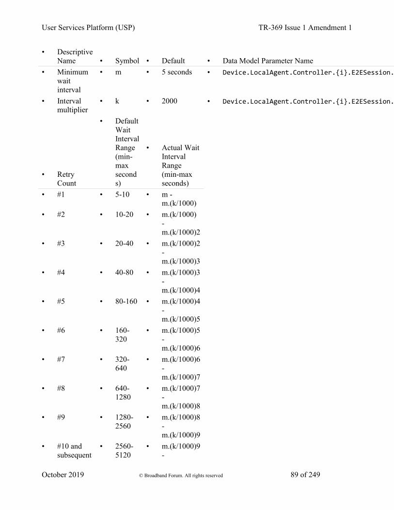
User Services Platform (USP) TR-369 Issue 1 Amendment 1
October 2019 © Broadband Forum. All rights reserved 89 of 249
• Descriptive Name • Symbol • Default • Data Model Parameter Name
• Minimum wait interval
• m • 5 seconds • Device.LocalAgent.Controller.{i}.E2ESession.
• Interval multiplier
• k • 2000 • Device.LocalAgent.Controller.{i}.E2ESession.
• Retry Count
• Default Wait Interval Range (min-max seconds)
• Actual Wait Interval Range (min-max seconds)
• #1 • 5-10 • m - m.(k/1000)
• #2 • 10-20 • m.(k/1000) - m.(k/1000)2
• #3 • 20-40 • m.(k/1000)2 - m.(k/1000)3
• #4 • 40-80 • m.(k/1000)3 - m.(k/1000)4
• #5 • 80-160 • m.(k/1000)4 - m.(k/1000)5
• #6 • 160-320
• m.(k/1000)5 - m.(k/1000)6
• #7 • 320-640
• m.(k/1000)6 - m.(k/1000)7
• #8 • 640-1280
• m.(k/1000)7 - m.(k/1000)8
• #9 • 1280-2560
• m.(k/1000)8 - m.(k/1000)9
• #10 and subsequent
• 2560-5120
• m.(k/1000)9 -
User Services Platform (USP) TR-369 Issue 1 Amendment 1
October 2019 © Broadband Forum. All rights reserved 90 of 249
m.(k/1000)10
R-E2E.11 - Beginning with the tenth retry attempt, the Agent MUST choose from the fixed maximum range. The Agent will continue to retry a failed session establishment until a USP message is successfully received by the Agent or until the SessionExpiration time is reached.
R-E2E.12 – Once a USP Record is successfully received, the Agent MUST reset the Session Context retry count to zero for the next Session Context establishment.
R-E2E.13 – If a reboot of the Agent occurs, the Agent MUST reset the Session Context retry count to zero for the next Session Context establishment.
12.2.2 USP Record Exchange
Once a Session Context is established, USP Records are created to exchange payloads in the Session Context. USP Records are uniquely identified by their originating USP Endpoint Identifier (from_id), Session Context identifier (session_id) and USP Record sequence identifier (sequence_id).
12.2.2.1 USP Record Transmission
When an originating USP Endpoint transmits a USP Record, it creates the USP Record with a monotonically increasing sequence identifier (sequence_id).
R-E2E.14 – When an originating USP Endpoint transmits a USP Record, it MUST set the sequence identifier of the first transmitted USP Record in the Session Context to 1.
R-E2E.15 – When an originating USP Endpoint transmits additional USP Records, the originating USP Endpoint MUST monotonically increase the sequence identifier from the last transmitted USP Record in the Session Context by one (1).
To communicate the sequence identifier of the last USP Record received by a receiving USP Endpoint to the originating USP Endpoint, whenever a USP Endpoint transmits a USP Record the originating USP Endpoint communicates the next sequence identifier of a USP Record it expects to receive in the expected_id field. The receiving USP Endpoint uses this information to maintain its buffer of outgoing (transmitted) USP Records such that any USP Records with a sequence identifier less than the expected_id can be removed from the receiving USP Endpoints buffer of transmitted USP Records for this Session Context.
R-E2E.16 – When an originating USP Endpoint transmits a USP Record, the originating USP Endpoint MUST preserve it in an outgoing buffer, for fulfilling retransmit requests, until the originating USP Endpoint receives a USP Record from the receiving USP Endpoint with a greater expected_id.
User Services Platform (USP) TR-369 Issue 1 Amendment 1
October 2019 © Broadband Forum. All rights reserved 91 of 249
R-E2E.17 – When an originating USP Endpoint transmits a USP Record, the originating USP Endpoint MUST inform the receiving USP Endpoint of the next sequence identifier in the Session Context for a USP Record it expects to receive.
12.2.2.2 Payload Security within the Session Context
The value of the payload_security field defines the type of payload security that is performed in the Session Context. Once a Session Context is established the payload security stays the same throughout the lifetime of the Session Context.
R-E2E.18 – The originating USP Endpoint MUST use the same value in the payload_security field for all USP Records within a Session Context.
12.2.2.3 USP Record Reception
USP Records received by a USP Endpoint have information that is used by the receiving USP Endpoint to process:
1. The payload contained within the USP Record,
2. A request to retransmit a USP Record, and
3. The contents of the outgoing buffer to clear the USP Records that the originating USP Endpoint has indicated it has received from the receiving USP Endpoint.
As USP Records can be received out of order or not at all, the receiving USP Endpoint only begins to process a USP Record when the sequence_id field of the USP Record in the Session Context is the sequence_id field that the receiving USP Endpoint expects to receive. The following figure depicts the high-level processing for USP Endpoints that receive a USP Record.
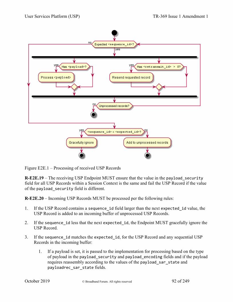
User Services Platform (USP) TR-369 Issue 1 Amendment 1
October 2019 © Broadband Forum. All rights reserved 92 of 249
Figure E2E.1 – Processing of received USP Records
R-E2E.19 – The receiving USP Endpoint MUST ensure that the value in the payload_security field for all USP Records within a Session Context is the same and fail the USP Record if the value of the payload_security field is different.
R-E2E.20 – Incoming USP Records MUST be processed per the following rules:
1. If the USP Record contains a sequence_id field larger than the next expected_id value, the USP Record is added to an incoming buffer of unprocessed USP Records.
2. If the sequence_id less that the next expected_id, the Endpoint MUST gracefully ignore the USP Record.
3. If the sequence_id matches the expected_id, for the USP Record and any sequential USP Records in the incoming buffer:
1. If a payload is set, it is passed to the implementation for processing based on the type of payload in the payload_security and payload_encoding fields and if the payload requires reassembly according to the values of the payload_sar_state and payloadrec_sar_state fields.
User Services Platform (USP) TR-369 Issue 1 Amendment 1
October 2019 © Broadband Forum. All rights reserved 93 of 249
2. If a retransmit_id field is set, the USP Record with the sequence identifier of the retransmit_id field is resent from the outgoing buffer.
4. The expected_id field for new outgoing records is set to sequence_id field + 1 of this USP Record.
12.2.2.3.1 Failure Handling of Received USP Records Within a Session Context
When a receiving USP Endpoint fails to either buffer or successfully process a USP Record, the receiving USP Endpoint initiates a new Session Context.
R-E2E.21 – When a USP Endpoint that receives a USP Record within a Session Context that fails to buffer or successfully process (e.g., decode, decrypt, retransmit) the USP Endpoint MUST start a new Session Context.
12.2.2.4 USP Record Retransmission
An Agent or Controller can request to receive USP Records that it deems as missing at any time within the Session Context. The originating USP Endpoint requests a USP Record from the receiving USP Endpoint by placing the sequence identifier of the requested USP Record in the retransmit_id field of the USP Record to be transmitted.
The receiving USP Endpoint will determine if USP Record exists and then re-send the USP Record to the originating USP Endpoint.
If the USP Record doesn’t exist, the USP Endpoint that received the USP Record will consider the USP Record as failed and perform the failure processing as defined in section Failure Handling of Received USP Records.
To guard against excessive requests to retransmit a specific USP Record, the USP Endpoint checks to see if the number of times the USP Record has been retransmitted is greater than or equal to maximum times a USP Record can be retransmitted as defined in the Device.LocalAgent.Controller.{i}.E2ESession.MaxRetransmitTries Parameter. If this condition is met, then the USP Endpoint that received the USP Record with the retransmit request will consider the USP Record as failed and perform the failure processing as defined in section Failure Handling of Received USP Records.
12.2.3 Guidelines for Handling Session Context Restarts
A Session Context can be restarted for a number of reasons (e.g., sequence id exhaustion, errors, manual request). When a Session Context is restarted, the USP Endpoints could have USP Records that have not been transmitted, received or processed. This section provides guidance for USP Endpoints when the Session Context is restarted.
User Services Platform (USP) TR-369 Issue 1 Amendment 1
October 2019 © Broadband Forum. All rights reserved 94 of 249
The originating endpoint is responsible for determining the policy for recovering from USP Records that were not transmitted. For example, the policy could be to resend the USP Message conveyed through the USP Record, or to simply discard the USP Message.
R-E2E.22 – The receiving USP endpoint MUST successfully process the USP Record through the expected_id field that it last transmitted in the previous session.
When a USP Endpoint receives a USP Record that cannot pass an integrity check or that has an incorrect value in the session_id element, the Session Context is restarted.
R-E2E.23 – USP Records that do not pass integrity checks MUST be silently ignored and the receiving USP Endpoint MUST restart the Session Context.
This allows keys to be distributed and enabled under the old session keys and then request a session restarted under the new keys.
R-E2E.24 – USP Records that pass the integrity check but have an invalid value in the session_id field MUST be silently ignored and the receiving USP Endpoint MUST restart the Session Context.
12.2.4 Segmented Message Exchange
In many complex deployments, a USP Message will be transferred across Message Transfer Protocol (MTP) proxies that are used to forward the USP Message between Controllers and Agents that use different transport protocols.
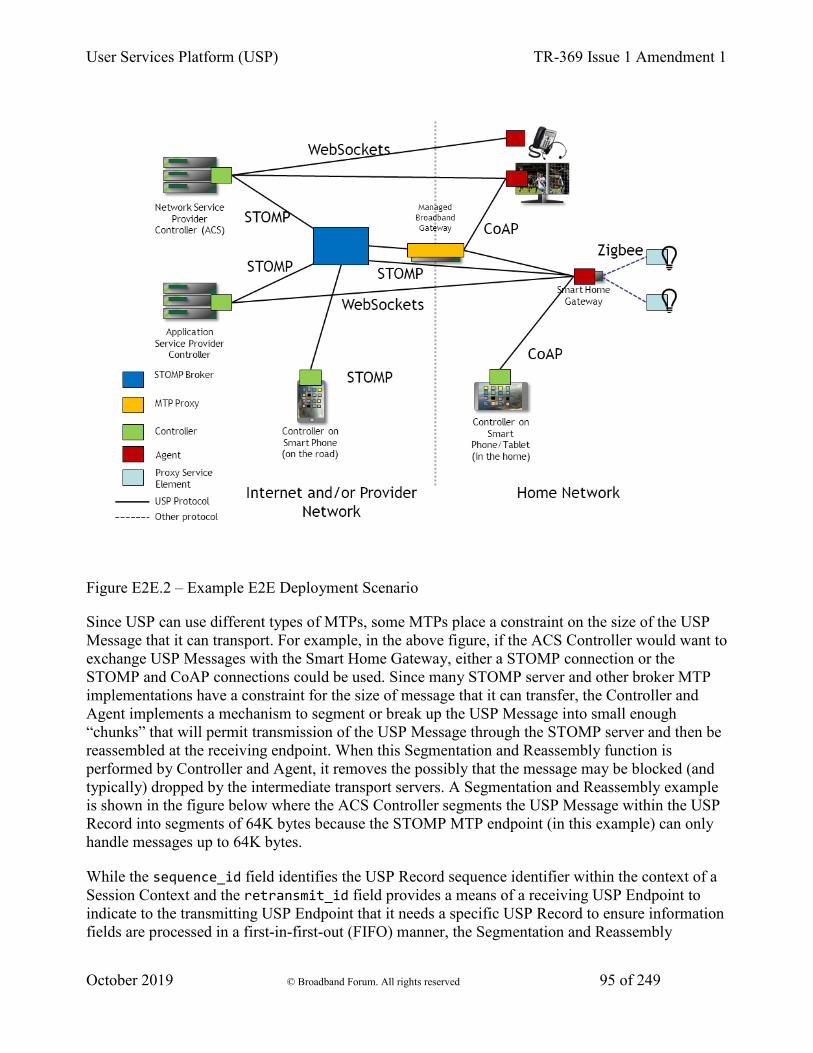
User Services Platform (USP) TR-369 Issue 1 Amendment 1
October 2019 © Broadband Forum. All rights reserved 95 of 249
Figure E2E.2 – Example E2E Deployment Scenario
Since USP can use different types of MTPs, some MTPs place a constraint on the size of the USP Message that it can transport. For example, in the above figure, if the ACS Controller would want to exchange USP Messages with the Smart Home Gateway, either a STOMP connection or the STOMP and CoAP connections could be used. Since many STOMP server and other broker MTP implementations have a constraint for the size of message that it can transfer, the Controller and Agent implements a mechanism to segment or break up the USP Message into small enough “chunks” that will permit transmission of the USP Message through the STOMP server and then be reassembled at the receiving endpoint. When this Segmentation and Reassembly function is performed by Controller and Agent, it removes the possibly that the message may be blocked (and typically) dropped by the intermediate transport servers. A Segmentation and Reassembly example is shown in the figure below where the ACS Controller segments the USP Message within the USP Record into segments of 64K bytes because the STOMP MTP endpoint (in this example) can only handle messages up to 64K bytes.
While the sequence_id field identifies the USP Record sequence identifier within the context of a Session Context and the retransmit_id field provides a means of a receiving USP Endpoint to indicate to the transmitting USP Endpoint that it needs a specific USP Record to ensure information fields are processed in a first-in-first-out (FIFO) manner, the Segmentation and Reassembly
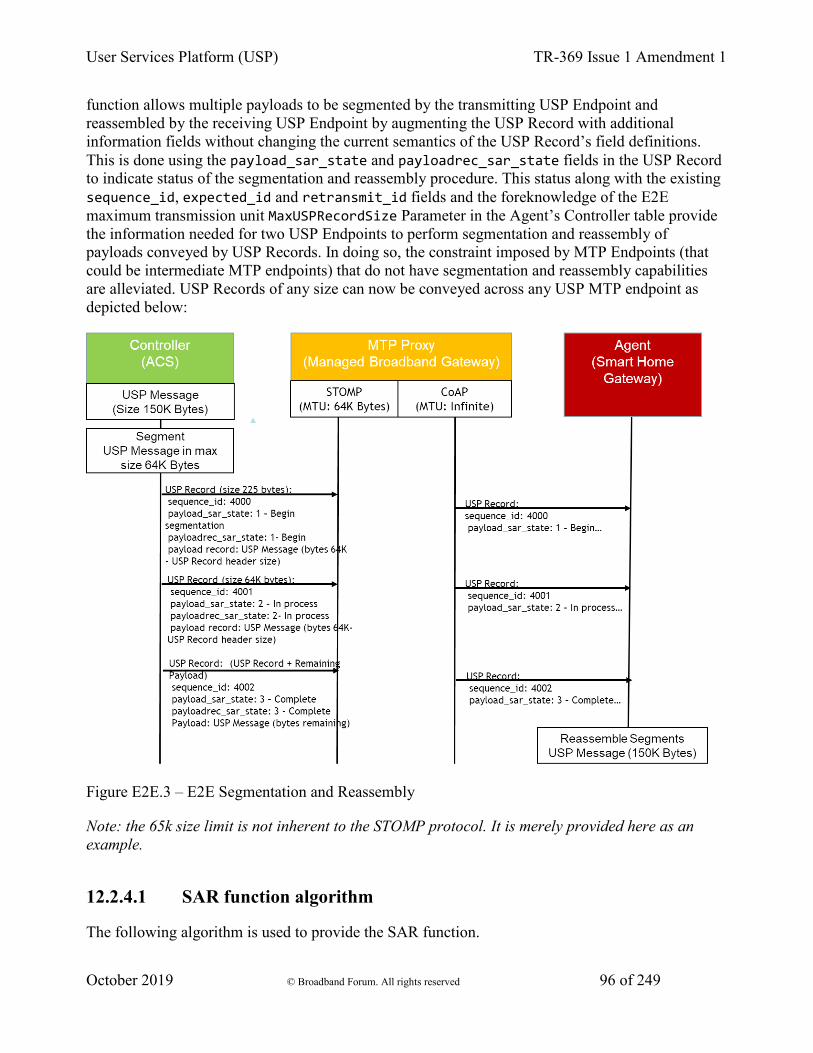
User Services Platform (USP) TR-369 Issue 1 Amendment 1
October 2019 © Broadband Forum. All rights reserved 96 of 249
function allows multiple payloads to be segmented by the transmitting USP Endpoint and reassembled by the receiving USP Endpoint by augmenting the USP Record with additional information fields without changing the current semantics of the USP Record’s field definitions. This is done using the payload_sar_state and payloadrec_sar_state fields in the USP Record to indicate status of the segmentation and reassembly procedure. This status along with the existing sequence_id, expected_id and retransmit_id fields and the foreknowledge of the E2E maximum transmission unit MaxUSPRecordSize Parameter in the Agent’s Controller table provide the information needed for two USP Endpoints to perform segmentation and reassembly of payloads conveyed by USP Records. In doing so, the constraint imposed by MTP Endpoints (that could be intermediate MTP endpoints) that do not have segmentation and reassembly capabilities are alleviated. USP Records of any size can now be conveyed across any USP MTP endpoint as depicted below:
Figure E2E.3 – E2E Segmentation and Reassembly
Note: the 65k size limit is not inherent to the STOMP protocol. It is merely provided here as an example.
12.2.4.1 SAR function algorithm
The following algorithm is used to provide the SAR function.
User Services Platform (USP) TR-369 Issue 1 Amendment 1
October 2019 © Broadband Forum. All rights reserved 97 of 249
12.2.4.1.1 Originating USP Endpoint
For each USP Message segment the Payload:
1. Compose the USP Message.
2. If payload_security is TLS12, encrypt the USP Message. TLS will segment the encrypted Message per the maximum allowed TLS record size.
1. If all TLS records + Record header elements are less than the maximum allowed USP Record size, then a single USP Record is sent.
2. Otherwise segmentation of the USP Record will need to be done.
1. If the record size of a single TLS record + USP Record header elements is less than the maximum allowed USP Record size, exactly one TLS record can be included in a USP Record.
2. If the TLS record size + Record header elements is greater than the maximum allowed USP Record size, the TLS record is segmented across multiple USP Records.
3. If the Message is transmitted using PLAINTEXT and the Message + Record header elements are greater than the maximum allowed USP Record size, the USP Record is segmented.
4. Set the payload_sar_state field for each transmitted Record.
1. If there is only one Record, payload_sar_state = NONE (0).
2. If there is more than one USP Record, the payload_sar_state field is set to BEGIN (1) on the first Record, COMPLETE (3) on the last Record, and INPROCESS (2) on all Records between the two.
5. Set the payloadrec_sar_state field for each transmitted Record.
1. If there is only one Record or one Secure Message Exchange TLS record per USP Record, payloadrec_sar_state = NONE (0).
2. If Secure Message Exchange TLS records or a PLAINTEXT payload are segmented across multiple USP Records, payloadrec_sar_state = BEGIN (1) on a Record that contains the initial segment of a TLS record or PLAINTEXT payload, COMPLETE (3) on a Record that contains the final segment of a TLS record or PLAINTEXT payload, and INPROCESS (2) on all Records containing segments between initial and final segments of a TLS record or PLAINTEXT payload.
6. Each Record is sent (within a Session Context) using the procedures defined in the USP Record Message Exchange section above.
User Services Platform (USP) TR-369 Issue 1 Amendment 1
October 2019 © Broadband Forum. All rights reserved 98 of 249
The effect of the above rules for PLAINTEXT payloads or for Secure Message Exchange with a single TLS record is that payloadrec_sar_state will be the same as payload_sar_state for all Records used to communicate the USP Message.
Note: The maximum allowed USP Record size can be exposed via the data model using the MaxUSPRecordSize parameter.
12.2.4.1.2 Receiving Endpoint
For each USP Message reassemble the segmented payload:
1. When a USP Record that indicates segmentation has started, store the USP Records until a USP Record is indicated to be complete. A completed segmentation is where the USP Record’s payload_sar_state and payloadrec_sar_state have a value of COMPLETE (3).
2. Follow the procedures in USP Record Retransmission to retransmit any USP Records that were not received.
3. Once the USP Record is received that indicates that the segmentation is complete, reassemble the payload by appending the payloads using the monotonically increasing sequence_id field’s value from the smaller number to larger sequence numbers. The reassembly keeps the integrity of the instances of the payload field’s payload records. To keep the integrity of the payload record, the payload record is reassembled using the payloadrec_sar_state values.
4. Reassembly of the payload that represents the USP Message is complete.
If the segmentation and reassembly fails for any reason, the USP Endpoint that received the segmented USP Records will consider the last received USP Record as failed and perform the failure processing as defined in section Failure Handling of Received USP Records.
12.2.4.2 Segmentation Examples
The following examples show the values assigned to payload_sar_state and payloadrec_sar_state fields for various permutations of payload_security, and maximum USP Record size and Secure Message Exchange maximum TLS record size relative to the size of the USP Message. The examples are not exhaustive.
Case 1: payload_security = PLAINTEXT, single USP Record
Conditions:
1. Maximum USP Record size > size of (USP Message + USP Record header)
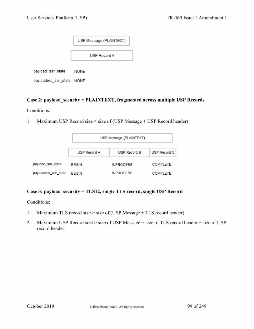
User Services Platform (USP) TR-369 Issue 1 Amendment 1
October 2019 © Broadband Forum. All rights reserved 99 of 249
Case 2: payload_security = PLAINTEXT, fragmented across multiple USP Records
Conditions:
1. Maximum USP Record size < size of (USP Message + USP Record header)
Case 3: payload_security = TLS12, single TLS record, single USP Record
Conditions:
1. Maximum TLS record size > size of (USP Message + TLS record header)
2. Maximum USP Record size > size of USP Message + size of TLS record header + size of USP record header
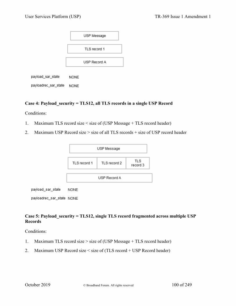
User Services Platform (USP) TR-369 Issue 1 Amendment 1
October 2019 © Broadband Forum. All rights reserved 100 of 249
Case 4: Payload_security = TLS12, all TLS records in a single USP Record
Conditions:
1. Maximum TLS record size < size of (USP Message + TLS record header)
2. Maximum USP Record size > size of all TLS records + size of USP record header
Case 5: Payload_security = TLS12, single TLS record fragmented across multiple USP Records
Conditions:
1. Maximum TLS record size > size of (USP Message + TLS record header)
2. Maximum USP Record size < size of (TLS record + USP Record header)

User Services Platform (USP) TR-369 Issue 1 Amendment 1
October 2019 © Broadband Forum. All rights reserved 101 of 249
Case 6: Payload_security = TLS12, multiple TLS records, one TLS record per USP Record
Conditions:
1. Maximum TLS record size < size of (USP Message + TLS record header)
2. Maximum USP Record size > maximum TLS record size + size of USP Record header
3. Maximum USP Record size < size of USP Message + size of TLS record header + size of USP record header
Case 7: Payload_security = TLS12, multiple TLS records, some TLS records fragmented across multiple USP Records
Conditions:
1. Maximum TLS record size < size of (USP Message + TLS record header)
2. Maximum USP Record size < size of (some TLS records + USP Record header)
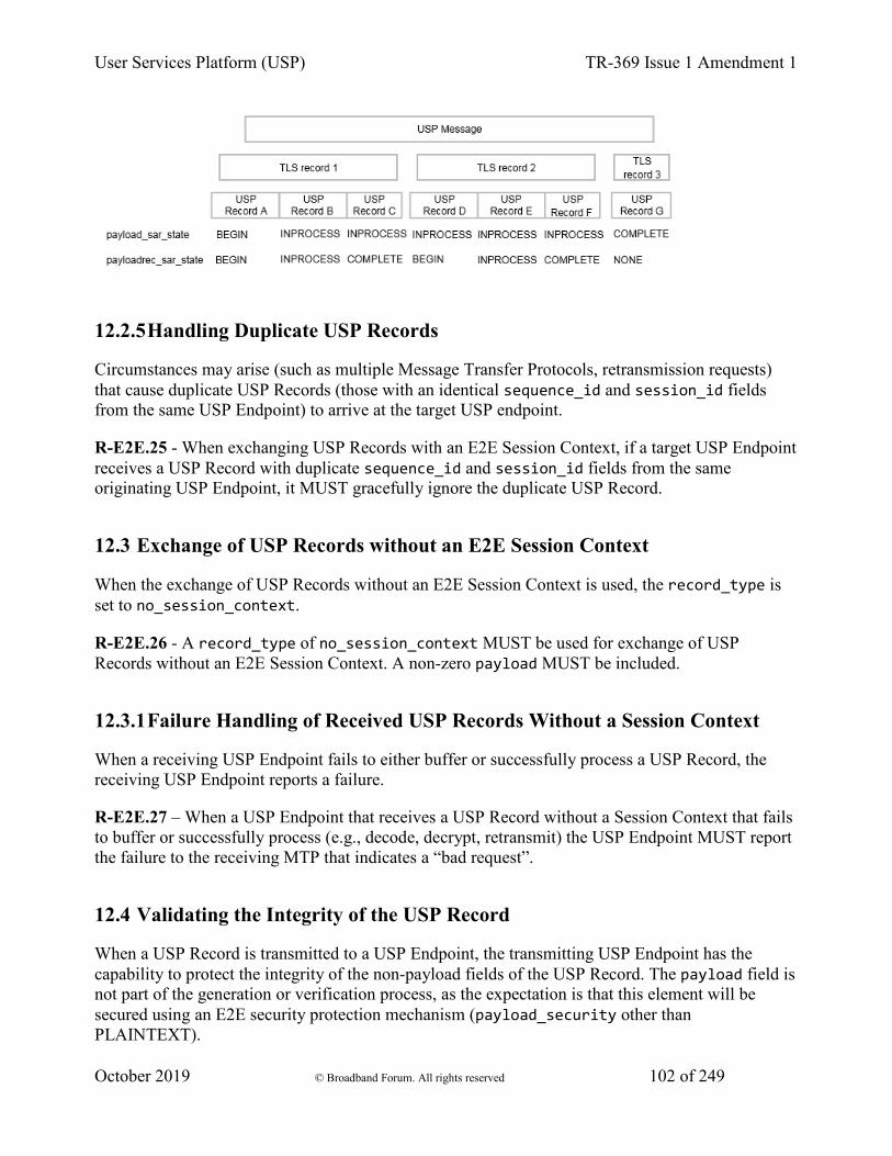
User Services Platform (USP) TR-369 Issue 1 Amendment 1
October 2019 © Broadband Forum. All rights reserved 102 of 249
12.2.5 Handling Duplicate USP Records
Circumstances may arise (such as multiple Message Transfer Protocols, retransmission requests) that cause duplicate USP Records (those with an identical sequence_id and session_id fields from the same USP Endpoint) to arrive at the target USP endpoint.
R-E2E.25 - When exchanging USP Records with an E2E Session Context, if a target USP Endpoint receives a USP Record with duplicate sequence_id and session_id fields from the same originating USP Endpoint, it MUST gracefully ignore the duplicate USP Record.
12.3 Exchange of USP Records without an E2E Session Context
When the exchange of USP Records without an E2E Session Context is used, the record_type is set to no_session_context.
R-E2E.26 - A record_type of no_session_context MUST be used for exchange of USP Records without an E2E Session Context. A non-zero payload MUST be included.
12.3.1 Failure Handling of Received USP Records Without a Session Context
When a receiving USP Endpoint fails to either buffer or successfully process a USP Record, the receiving USP Endpoint reports a failure.
R-E2E.27 – When a USP Endpoint that receives a USP Record without a Session Context that fails to buffer or successfully process (e.g., decode, decrypt, retransmit) the USP Endpoint MUST report the failure to the receiving MTP that indicates a “bad request”.
12.4 Validating the Integrity of the USP Record
When a USP Record is transmitted to a USP Endpoint, the transmitting USP Endpoint has the capability to protect the integrity of the non-payload fields of the USP Record. The payload field is not part of the generation or verification process, as the expectation is that this element will be secured using an E2E security protection mechanism (payload_security other than PLAINTEXT).
User Services Platform (USP) TR-369 Issue 1 Amendment 1
October 2019 © Broadband Forum. All rights reserved 103 of 249
The integrity of the USP Record is required to be validated when the USP Record cannot be protected by the underlying MTP.
R-E2E.28 - When a USP Record is received or transmitted the following conditions MUST apply for the USP Record to be considered protected by the underlying MTP:
• The MTP is encrypted per requirements in the applicable MTP section
• The peer MTP certificate contains an Endpoint ID and this Endpoint ID is the same as the USP Record from_id field.
• The peer MTP certificate is that of a Trusted Broker.
R-E2E.29 – Unless protected by the underlying MTP, when a USP Endpoint transmits a USP Record, the USP Endpoint MUST protect the integrity of the non-payload portion of the USP Record.
R-E2E.30 – When a USP Endpoint receives a USP Record, the USP Endpoint MUST verify the integrity of the non-payload portion of the USP Record when the USP Record contains the mac_signature field or the USP Endpoint is not protected by the underlying MTP.
The integrity of the non-payload fields is accomplished by the transmitting USP Endpoint generating a Message Authentication Code (MAC) or signature of the non-payload fields which is then placed into the mac_signature field where the receiving USP Endpoint then verifies the MAC or signature as appropriate. The method to generate and validate MAC or signature depends on the value of the payload_security field. If the value of the payload_security field is PLAINTEXT then the integrity validation method always uses the signature method described in section Using the Signature Method to Validate the Integrity of USP Records. If the value of the payload_security field is TLS12 then the validation method that is used is dependent on whether the TLS handshake has been completed. If the TLS handshake has not been completed, the signature method described in section Using the Signature Method to Validate the Integrity of USP Records is used otherwise the MAC method described in section Using TLS to Validate the Integrity of USP Records is used.
12.4.1 Using the Signature Method to Validate the Integrity of USP Records
When the transmitting USP Endpoint protects the integrity of the non-payload fields of the USP Record using the signature method in this section, the non-payload fields are protected by signing a hash of the non-payload fields using the private key of the sending USP Endpoint’s certificate. The receiving USP Endpoint then verifies the integrity using either the public key of the certificate in the USP Record sender_cert field or of the certificate used for Secure Message Exchange.
This signature method uses a SHA-256 hash algorithm that generates a signature for the hash using the Digital Signature Standard (DSS) scheme as defined in FIPS PUB 186-4 Digital Signature Standard (DSS). To reduce the burden of requiring a strong source of randomness, the signature algorithm may apply the method described in RFC 6979 to deterministically derive encryption parameters.
User Services Platform (USP) TR-369 Issue 1 Amendment 1
October 2019 © Broadband Forum. All rights reserved 104 of 249
R-E2E.31 – When using the signature method to protect the integrity of the non-payload portion of the USP Record, the transmitting USP Endpoint MUST protect the integrity using the ECDSA scheme as defined in FIPS PUB 186-4 Digital Signature Standard (DSS), using the SHA-256 hash algorithm, as defined in FIPS PUB 180-4 Secure Hash Standard (SHS), to sign and verify the protection. The transmitting USP Endpoint MUST create the signature using the private key of the transmitting USP Endpoint’s certificate. The receiving USP Endpoint MUST verify the signature using the public key of the transmitted sender’s certificate.
12.4.2 Using TLS to Validate the Integrity of USP Records
When the transmitting and receiving USP Endpoints have established a TLS session between the USP Endpoints, the transmitting USP Endpoint no longer needs to generate a signature or transmit the sender’s certificate with the USP Record. Instead the transmitting USP Record generates a MAC that is verified by the receiving USP Endpoint. The MAC ensures the integrity of the non-payload fields of the USP Record. The MAC mechanism used in USP for this purpose is the SHA-256 keyed-Hash Message Authentication Code (HMAC) algorithm. The key used for the HMAC algorithm uses a Key Derivation Function (KDF) in accordance with RFC 5869(https://tools.ietf.org/html/rfc5869) and requires the following inputs to be known by the USP Endpoints involved in the generation and validation of the MAC: length of the output MAC, salt, key and application context information (i.e., KDF info field). The application context information uses a constant value for all USP implementations (“USP_Record”) and the length is fixed at 32 octets. The salt and key inputs are based on the underlying mechanism used to protect the payload of the USP Record. For TLS, the salt and key are taken from the TLS session once TLS negotiation is completed. The input key to the KDF uses the master key of the TLS session. The salt depends on role played by the USP Endpoint in the TLS Session (i.e., TLS session’s client or server random).
R-E2E.32 – When generating or validating the MAC or signature to protect the integrity of the USP Record, the sequence of the non-payload fields MUST use the field identifier of the USP Record’s protobuf specification proceeding from lowest to highest. The non-payload fields in the Record definition (other than the mac_signature field itself) MUST be used first and then the fields of the SessionContextRecord if applicable.
R-E2E.32.1 – When generating or validating the MAC or signature, all non-payload fields MUST be appended as byte arrays and fed into the MAC or signature generation function with the following conditions:
• uint64 types MUST be passed as 8 bytes in big endian ordering
• uint32 types MUST be passed as 4 bytes in big endian ordering
• enum types MUST be treated as uint32
• string types MUST be passed as UTF-8 encoded byte array
• bytes types MUST be passed as is
User Services Platform (USP) TR-369 Issue 1 Amendment 1
October 2019 © Broadband Forum. All rights reserved 105 of 249
R-E2E.33 – If using the TLS MAC method to protect the integrity of a USP Record, and a USP Endpoint receives a USP Record, the USP Endpoint MUST verify the MAC using the SHA-256 HMAC algorithm for the non-payload portion of the USP Record.
R-E2E.34 – If using the TLS MAC method to protect the integrity of a USP Record, when generating or validating the MAC of the USP Record, the sequence of the non-payload fields MUST use the field identifier of the USP Record’s protobuf specification proceeding from lowest to highest.
R-E2E.35 – If using the TLS MAC method to protect the integrity of a USP Record, when generating or validating the MAC of the USP Record, the USP Endpoint MUST derive the key using the KDF as defined in RFC 5869(https://tools.ietf.org/html/rfc5869).
R-E2E.36 – If using the TLS MAC method to protect the integrity of a USP Record, when generating or validating the MAC of the USP Record, the USP Endpoint MUST use the application context information value of “USP_Record”.
R-E2E.37 – If using the TLS MAC method to protect the integrity of a USP Record, when generating or validating the MAC of the USP Record, the USP Endpoint MUST use the MAC length of 32.
R-E2E.38 – If using the TLS MAC method to protect the integrity of a USP Record, when generating or validating the MAC of the USP Record and the USP Endpoint uses TLS to secure the payload of the USP Record, the USP Endpoint MUST derive the key from the negotiated TLS session’s master key.
R-E2E.39 – If using the TLS MAC method to protect the integrity of a USP Record, when generating the MAC of the USP Record and the USP Endpoint uses TLS to secure the payload of the USP Record, the USP Endpoint MUST use TLS session’s client or server random for the salt depending on the role the USP Endpoint plays in the TLS session (i.e., the TLS client uses the client random and the TLS server uses the server random).
12.5 Secure Message Exchange
While message transport bindings implement point-to-point security, the existence of broker-based message transports and transport proxies creates a need for end-to-end security within the USP protocol. End-to-end security is established by securing the payloads prior to segmentation and transmission by the originating USP Endpoint and the decryption of reassembled payloads by the receiving USP Endpoint. The indication whether and how the USP Message has been secured is via the payload_security field. This field defines the security protocol or mechanism applied to the USP payload, if any. This section describes the payload security protocols supported by USP.
12.5.1 TLS Payload Encapsulation
USP employs TLS as one security mechanism for protection of USP payloads in Agent-Controller message exchanges.
User Services Platform (USP) TR-369 Issue 1 Amendment 1
October 2019 © Broadband Forum. All rights reserved 106 of 249
While traditionally deployed over reliable streams, TLS is a record-based protocol that can be carried over datagrams, with considerations taken for reliable and in-order delivery. To aid interoperability, USP endpoints are initially limited to a single cipher specification, though future revisions of the protocol may choose to expand cipher support.
R-E2E.40 – When using TLS to protect USP payloads in USP Records, USP Endpoints MUST implement TLS 1.2 or later (with backward compatibility to TLS 1.2) with the ECDHE-ECDSA-AES128-GCM-SHA256 cipher and P-256 curve.
Note: The cipher listed above requires a USP Endpoint acting as the TLS server to use X.509 certificates signed with ECDSA and Diffie-Hellman key exchange credentials to negotiate the cipher.
12.5.1.1 Session Handshake
When TLS is used as a payload protection mechanism for USP Message, TLS requires the use of the Session Context to negotiate its TLS session. The USP Endpoint that initiated the Session Context will act in the TLS client role when establishing the security layer. The security layer is constructed using a standard TLS handshake, encapsulated within one or more of the above-defined USP Record payload datagrams. Per the TLS protocol, establishment of a new TLS session requires two round-trips.
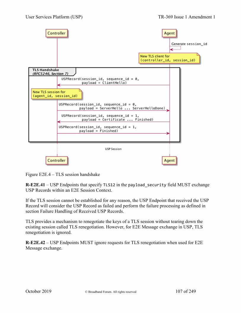
User Services Platform (USP) TR-369 Issue 1 Amendment 1
October 2019 © Broadband Forum. All rights reserved 107 of 249
Figure E2E.4 – TLS session handshake
R-E2E.41 – USP Endpoints that specify TLS12 in the payload_security field MUST exchange USP Records within an E2E Session Context.
If the TLS session cannot be established for any reason, the USP Endpoint that received the USP Record will consider the USP Record as failed and perform the failure processing as defined in section Failure Handling of Received USP Records.
TLS provides a mechanism to renegotiate the keys of a TLS session without tearing down the existing session called TLS renegotiation. However, for E2E Message exchange in USP, TLS renegotiation is ignored.
R-E2E.42 – USP Endpoints MUST ignore requests for TLS renegotiation when used for E2E Message exchange.
User Services Platform (USP) TR-369 Issue 1 Amendment 1
October 2019 © Broadband Forum. All rights reserved 108 of 249
12.5.1.2 Authentication
USP relies upon peer authentication using X.509 certificates, as provided by TLS. Each USP endpoint identifier is identified within an X.509 certificate. The rules for authentication are provided in Authentication and Authorization.
R-E2E.43 – USP Endpoints MUST be mutually authenticated using X.509 certificates using the USP Endpoint identifier encoded within the X.509 certificates subjectAltName field.
13 Messages USP contains messages to create, read, update, and delete Objects, perform Object-defined operations, and allow agents to notify controllers of events. This is often referred to as CRUD with the addition of O (operate) and N (notify), or CRUD-ON.
Note: This version of the specification defines its messages in Protocol Buffers v3 (see encoding). This part of the specification may change to a more generic description (normative and non-normative) if further encodings are specified in future versions.
These sections describe the types of USP messages and the normative requirements for their flow and operation. USP messages are described in a protocol buffers schema, and the normative requirements for the individual fields of the schema are outlined below.
13.1 Encapsulation in a USP Record
All USP messages are encapsulated by a USP record. The definition of the USP record portion of a USP message, and the rules for managing transactional integrity, are described in End to End Message Exchange.
13.2 Requests, Responses and Errors
The three types of USP messages are Request, Response, and Error.
A request is a message sent from a source USP endpoint to a target USP endpoint that includes fields to be processed and returns a response or error. Unless otherwise specified, all requests have an associated response. Though the majority of requests are made from a Controller to an Agent, the Notify message follows the same format as a request but is sent from an Agent to a Controller.
R-MSG.0 - The target USP endpoint MUST respond to a request message from the source USP endpoint with either a response message or error message, unless otherwise specified (see Operate and Notify messages).
R-MSG.1 - The target USP endpoint MUST ignore or send an error message in response to messages it does not understand.
User Services Platform (USP) TR-369 Issue 1 Amendment 1
October 2019 © Broadband Forum. All rights reserved 109 of 249
R-MSG.2 - When the target USP endpoint is not required to send a response, the MTP endpoint that received the message MUST gracefully end the MTP message exchange. How the MTP gracefully ends the MTP message exchange is dependent on the type of MTP.
R-MSG.3 - In any USP Message originating from an Agent, unless otherwise specified, Path Names reported from the Agent’s Instantiated Data Model MUST use Instance Number Addressing.
13.2.1 Handling Duplicate Messages
Circumstances may arise (such as multiple Message Transfer Protocols) that cause duplicate messages (those with an identical message ID) to arrive at the target USP endpoint.
R-MSG.4 - If a target USP endpoint receives a message with a duplicate message ID before it has processed and sent a Response or Error to the original message, it MUST gracefully ignore the duplicate message.
For messages that require no response, it is up to the target endpoint implementation when to allow the same message ID to be re-used by the same source USP endpoint.
13.2.2 Example Message Flows
Successful request/response: In this successful message sequence, a Controller sends an Agent a request. The message header and body are parsed, the message is understood, and the Agent sends a response with the relevant information in the body.
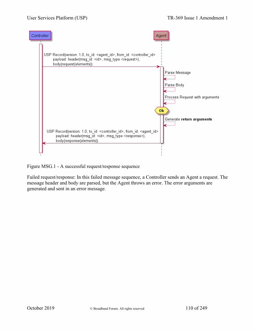
User Services Platform (USP) TR-369 Issue 1 Amendment 1
October 2019 © Broadband Forum. All rights reserved 110 of 249
Figure MSG.1 - A successful request/response sequence
Failed request/response: In this failed message sequence, a Controller sends an Agent a request. The message header and body are parsed, but the Agent throws an error. The error arguments are generated and sent in an error message.
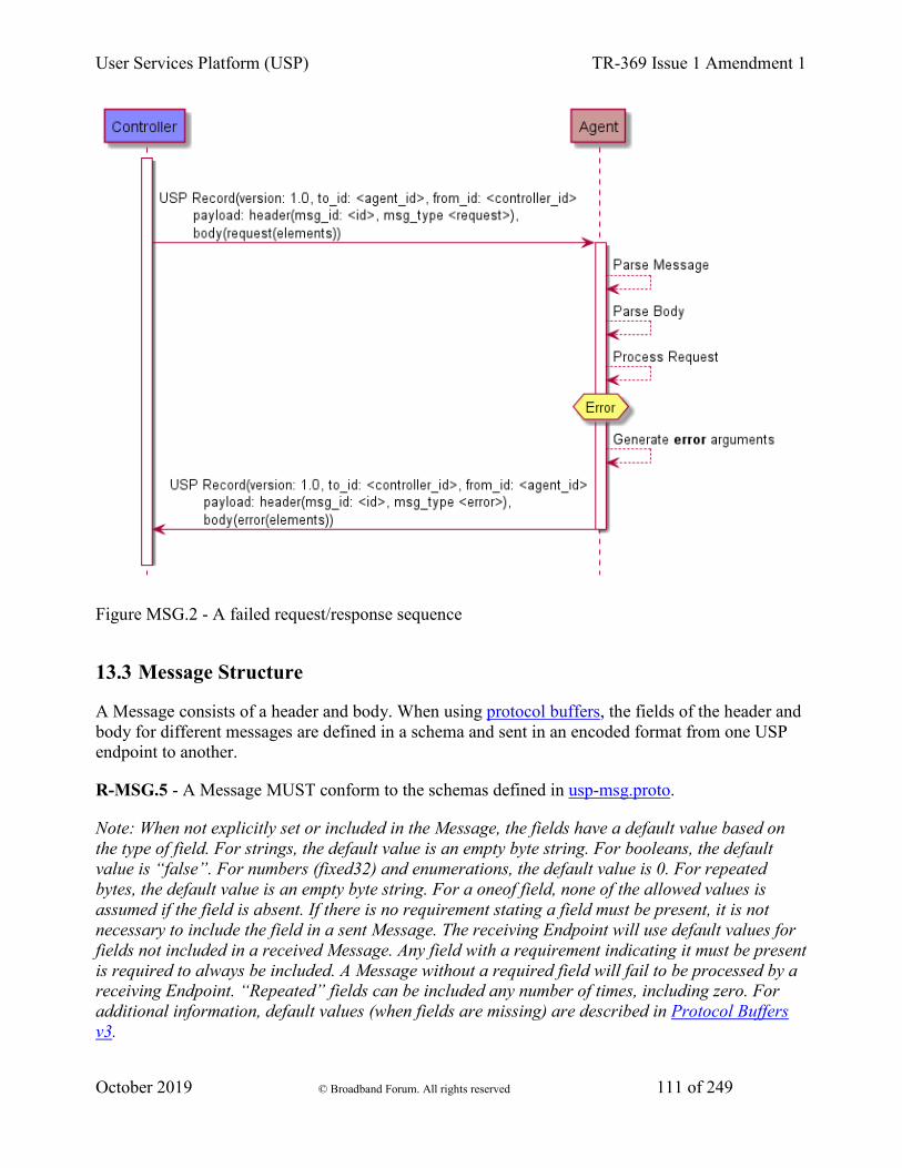
User Services Platform (USP) TR-369 Issue 1 Amendment 1
October 2019 © Broadband Forum. All rights reserved 111 of 249
Figure MSG.2 - A failed request/response sequence
13.3 Message Structure
A Message consists of a header and body. When using protocol buffers, the fields of the header and body for different messages are defined in a schema and sent in an encoded format from one USP endpoint to another.
R-MSG.5 - A Message MUST conform to the schemas defined in usp-msg.proto.
Note: When not explicitly set or included in the Message, the fields have a default value based on the type of field. For strings, the default value is an empty byte string. For booleans, the default value is “false”. For numbers (fixed32) and enumerations, the default value is 0. For repeated bytes, the default value is an empty byte string. For a oneof field, none of the allowed values is assumed if the field is absent. If there is no requirement stating a field must be present, it is not necessary to include the field in a sent Message. The receiving Endpoint will use default values for fields not included in a received Message. Any field with a requirement indicating it must be present is required to always be included. A Message without a required field will fail to be processed by a receiving Endpoint. “Repeated” fields can be included any number of times, including zero. For additional information, default values (when fields are missing) are described in Protocol Buffers v3.
User Services Platform (USP) TR-369 Issue 1 Amendment 1
October 2019 © Broadband Forum. All rights reserved 112 of 249
Every USP message contains a header and a body. The header contains basic destination and coordination information, and is separated to allow security and discovery mechanisms to operate. The body contains the message itself and its arguments.
Each of the message types and fields below are described with the field type according to Protocol Buffers version 3, followed by its name.
13.3.1 The USP Message
Header header
R-MSG.6 - A Message MUST contain exactly one header field.
Body body
The Message Body that must be present in every Message. The Body field contains either a Request, Response, or Error field.
R-MSG.7 - A Message MUST contain exactly one body field.
13.3.2 Message Header
The message header contains information on source and target of the message, as well as useful coordination information. Its fields include a message ID, the endpoint identifiers for the source and target endpoints, an optional reply-to identifier, and a field indicating the type of message.
The purpose of the message header is to provide basic information necessary for the target endpoint to process the message.
13.3.2.1 Message Header fields
string msg_id
A locally unique opaque identifier assigned by the Endpoint that generated this message.
R-MSG.8 - The msg_id field MUST be present in every Header.
R-MSG.9 - The msg_id field in the Message Header for a Response or Error that is associated with a Request MUST contain the message ID of the associated request. If the msg_id field in the Response or Error does not contain the message ID of the associated Request, the response or error MUST be ignored.
enum MsgType msg_type
This field contains an enumeration indicating the type of message contained in the message body. It is an enumeration of:
User Services Platform (USP) TR-369 Issue 1 Amendment 1
October 2019 © Broadband Forum. All rights reserved 113 of 249
ERROR (0) GET (1) GET_RESP (2) NOTIFY (3) SET (4) SET_RESP (5) OPERATE (6) OPERATE_RESP (7) ADD (8) ADD_RESP (9) DELETE (10) DELETE_RESP (11) GET_SUPPORTED_DM (12) GET_SUPPORTED_DM_RESP (13) GET_INSTANCES (14) GET_INSTANCES_RESP (15) NOTIFY_RESP (16) GET_SUPPORTED_PROTO (17) GET_SUPPORTED_PROTO_RESP (18)
R-MSG.10 - The msg_type field MUST be present in every Header. Though required, it is meant for information only. In the event this field differs from the req_type or resp_type in the message body (respectively), the type given in either of those elements SHOULD be regarded as correct.
13.3.3 Message Body
The message body contains the intended message and the appropriate fields for the message type.
Every message body contains exactly one message and its fields. When an Agent is the target endpoint, these messages can be used to create, read, update, and delete Objects, or execute Object-defined operations. When a Controller is the target endpoint, the message will contain a notification, response, or an error.
13.3.3.1 Message Body fields
oneof msg_body
This field contains one of the types given below:
Request request
This field indicates that the Message contains a request of a type given in the Request Message.
Response response
This field indicates that the Message contains a response of a type given in the Response Message.
Error error

User Services Platform (USP) TR-369 Issue 1 Amendment 1
October 2019 © Broadband Forum. All rights reserved 114 of 249
This field indicates that the Message contains an Error Message.
13.3.3.2 Request fields
oneof req_type
This field contains one of the types given below. Each indicates that the Message contains a Message of the given type.
Get get GetSupportedDM get_supported_dm GetInstances get_instances Set set Add add Delete delete Operate operate Notify notify GetSupportedProtocol get_supported_protocol
13.3.3.3 Response fields
oneof resp_type
This field contains one of the types given below. Each indicates that the Message contains a Message of the given type.
GetResp get_resp GetSupportedDMResp get_supported_dm_resp GetInstancesResp get_instances_resp SetResp set_resp AddResp add_resp DeleteResp delete_resp OperateResp operate_resp NotifyResp notify_resp GetSupportedProtocolResp get_supported_protocol_resp
13.3.3.4 Error fields
fixed32 err_code
This field contains a numeric code indicating the type of error that caused the overall message to fail.
string err_msg
This field contains additional information about the reason behind the error.
User Services Platform (USP) TR-369 Issue 1 Amendment 1
October 2019 © Broadband Forum. All rights reserved 115 of 249
repeated ParamError param_errs
This field is present in an Error Message in response to an Add or Set message when the allow_partial field is false and detailed error information is available for each Object or parameter that have caused the message to report an Error.
13.3.3.4.1 ParamError fields
string param_path
This field contains a Path Name to the Object or parameter that caused the error.
fixed32 err_code
This field contains a numeric code indicating the type of error that caused the message to fail.
string err_msg
This field contains additional information about the reason behind the error.
13.4 Creating, Updating, and Deleting Objects
The Add, Set, and Delete requests are used to create, configure and remove Objects that comprise Service fields.
13.4.1 Selecting Objects and Parameters
Each Add, Set, and Delete request operates on one or more paths. For the Add request, these paths are references to Multi-Instance Objects. For all other requests, these paths can contain either addressing based identifiers that match zero or one Object or search based identifiers that matches one or more Objects.
For Add and Set requests, each Object address or search is conveyed in an field that also contains a sub-field listing the parameters to update in the matched Objects.
The Add response contains details about the success or failure of the creation of the Object and the parameters set during its creation. In addition, it also returns those parameters that were set by the Agent upon creation of the Object.
For example, a Controller wants to create a new WiFi network on an Agent. It could use an Add message with the following fields:
allow_partial: false create_objs { obj_path: "Device.WiFi.SSID." param_settings {

User Services Platform (USP) TR-369 Issue 1 Amendment 1
October 2019 © Broadband Forum. All rights reserved 116 of 249
{ param: "LowerLayers" value: "Device.WiFi.Radio.1." required: true} { param: "SSID" value: "NewSSIDName" required: true} } }
The Agent’s response would include the object created (with its instance identifier) and the unique keys of the created object as defined in Device:2:
created_obj_results { requested_path: "Device.WiFi.SSID." oper_status { oper_success { instantiated_path: ""Device.WiFi.SSID.4." unique_keys { { key: "BSSID" value: "112233445566"} { key: "Name" value: "GuestNetwork1"} { key: "Alias" value: "cpe-alias-1"} } } } }
13.4.2 Using Allow Partial and Required Parameters
The Add, Set, and Delete requests contain an field called “allow_partial”. This field determines whether or not the message should be treated as one complete configuration change, or a set of individual changes, with regards to the success or failure of that configuration.
For Delete, this is straightforward - if allow_partial is true, the Agent should return a Response message with affected_paths and unaffected_path_errs containing the successfully deleted Objects and unsuccessfully deleted objects, respectively. If allow_partial is false, the Agent should return an Error message if any Objects fail to be deleted.
For the Add and Set messages, parameter updates contain an field called “required”. This details whether or not the update or creation of the Object should fail if a required parameter fails.
This creates a hierarchy of error conditions for the Add and Set requests, such as:
User Services Platform (USP) TR-369 Issue 1 Amendment 1
October 2019 © Broadband Forum. All rights reserved 117 of 249
Parameter Error -> Object Error -> Message Error
If allow_partial is true, but one or more required parameters fail to be updated or configured, the creation or update of an individual Object fails. This results in an oper_failure in the oper_status field and updated_obj_result or created_obj_result returned in the Add or Set response.
If allow_partial is false, the failure of any required parameters will cause the update or creation of the Object to fail, which will cause the entire message to fail. In this case, the Agent returns an error message rather than a response message.
Both the oper_failure fields and Error messages contain an field called param_error, which contains fields of type ParamError. This is so that the Controller will receive the details of failed parameter updates regardless of whether or not the Agent returned a response message or error message.
The logic can be described as follows:
• allow_partial
• Required Parameters
• Required Parameter Failed
• Other Parameter Failed • Response/Error
• Oper_status of Object
• True/False • No • - • No • Response • oper_success • True/False • No • - • Yes • Response • oper_success • True/False • Yes • No • No • Response • oper_success • True/False • Yes • No • Yes • Response • oper_success • True • Yes • Yes • - • Response • oper_failure • False • Yes • Yes • - • Error • N/A
13.4.3 The Add Message
The Add message is used to create new Instances of Multi-Instance Objects in the Agent’s Instantiated Data Model.
13.4.3.1 Add Example
In this example, the Controller requests that the Agent create a new instance in the Device.LocalAgent.Controller table.
Add Request: header { msg_id: "52867" msg_type: ADD }

User Services Platform (USP) TR-369 Issue 1 Amendment 1
October 2019 © Broadband Forum. All rights reserved 118 of 249
body { request { add { allow_partial: true create_objs { obj_path: "Device.LocalAgent.Controller." param_settings { { param: "Enable" value: "True"} { param: "EndpointID" value: "controller-temp"} } } } } } Add Response: header { msg_id: "52867" msg_type: ADD_RESP } body { response { add_resp { created_obj_results { requested_path: "Device.LocalAgent.Controller." oper_status { oper_success { instantiated_path: "Device.LocalAgent.Controller.31185." unique_keys { key: "EndpointID" value: "controller-temp" } } } } } } }
13.4.3.2 Add Request fields
bool allow_partial
This field tells the Agent how to process the message in the event that one or more of the Objects specified in the create_objs argument fails creation.

User Services Platform (USP) TR-369 Issue 1 Amendment 1
October 2019 © Broadband Forum. All rights reserved 119 of 249
R-ADD.0 - If the allow_partial field is set to true, and no other exceptions are encountered, the Agent treats each Object matched in obj_path independently. The Agent MUST complete the creation of valid Objects regardless of the inability to create or update one or more Objects (see allow partial and required parameters).
R-ADD.1 - If the allow_partial field is set to false, and no other exceptions are encountered, the Agent treats each Object matched in obj_path holistically. A failure to create any one Object MUST cause the Add message to fail and return an Error Message (see allow partial and required parameters).
repeated CreateObject create_objs
This field contains a repeated set of CreateObject fields.
13.4.3.2.1 CreateObject fields
string obj_path
This field contains an Object Path to a writeable Table in the Agent’s Instantiated Data Model.
R-ADD.2 - The obj_path field in the CreateObject message of an Add Request MUST NOT contain Search Paths.
repeated CreateParamSetting param_settings
This field contains a repeated set of CreateParamSetting fields.
13.4.3.2.1.1 CreateParamSetting fields
string param
This field contains a relative path to a parameter of the Object specified in obj_path, or a parameter of a single instance sub-object of the Object specified in obj_path.
string value
This field contains the value of the parameter specified in the param field that the Controller would like to configure as part of the creation of this Object.
bool required
This field specifies whether the Agent should treat the creation of the Object specified in obj_path as conditional upon the successful configuration of this parameter (see allow partial and required parameters).
R-ADD.3 - If the required field is set to true, a failure to update this parameter MUST result in a failure to create the Object.
User Services Platform (USP) TR-369 Issue 1 Amendment 1
October 2019 © Broadband Forum. All rights reserved 120 of 249
13.4.3.3 Add Response fields
repeated CreatedObjectResult created_obj_results
A repeated set of CreatedObjectResult fields for each CreateObject field in the Add message.
13.4.3.3.1 CreatedObjectResult fields
string requested_path
This field returns the value of obj_paths in the CreateObject message associated with this CreatedObjectResult.
OperationStatus oper_status
The field contains a message of type OperationStatus that specifies the overall status for the creation of the Object specified in requested_path.
13.4.3.3.1.1 OperationStatus fields
oneof oper_status
This field contains one of the types given below. Each indicates that the field contains a message of the given type.
OperationFailure oper_failure
This message is used when the object given in requested_path failed to be created.
OperationSuccess oper_success
13.4.3.3.1.2 OperationFailure fields
fixed32 err_code
This field contains a numeric code indicating the type of error that caused the Object creation to fail. A value of 0 indicates the Object was created successfully.
string err_msg
This field contains additional information about the reason behind the error.
13.4.3.3.1.3 Operation Success fields
string instantiated_path
User Services Platform (USP) TR-369 Issue 1 Amendment 1
October 2019 © Broadband Forum. All rights reserved 121 of 249
This field contains the Object Instance Path of the created Object.
repeated ParameterError param_errs
This field returns a repeated set of ParameterError messages.
R-ADD.4 - If any of the parameters and values specified in the param_settings field fail to configure upon creation, this set MUST include one field describing each of the failed parameters and the reason for their failure.
map<string, string> unique_keys
This field contains a map of the local name and value for each supported parameter that is part of any of this Object’s unique keys.
R-ADD.5 - If the Controller did not include some or all of a unique key that the Agent supports in the param_settings field, the Agent MUST assign values to the unique key(s) and return them in the unique_keys.
R-ADD.6 - If the Controller does not have Read permission on any of the parameters specified in unique_keys, these parameters MUST NOT be returned in this field.
13.4.3.3.1.4 ParameterError fields
string param
This field contains the Relative Parameter Path to the parameter that failed to be set.
fixed32 err_code
This field contains the error code of the error that caused the parameter set to fail.
string err_msg
This field contains text related to the error specified by err_code.
13.4.3.4 Add Message Supported Error Codes
Appropriate error codes for the Add message include 7000-7019, 7026, and 7800-7999.
13.4.4 The Set Message
The Set Message is used to update the Parameters of existing Objects in the Agent’s Instantiated Data Model.
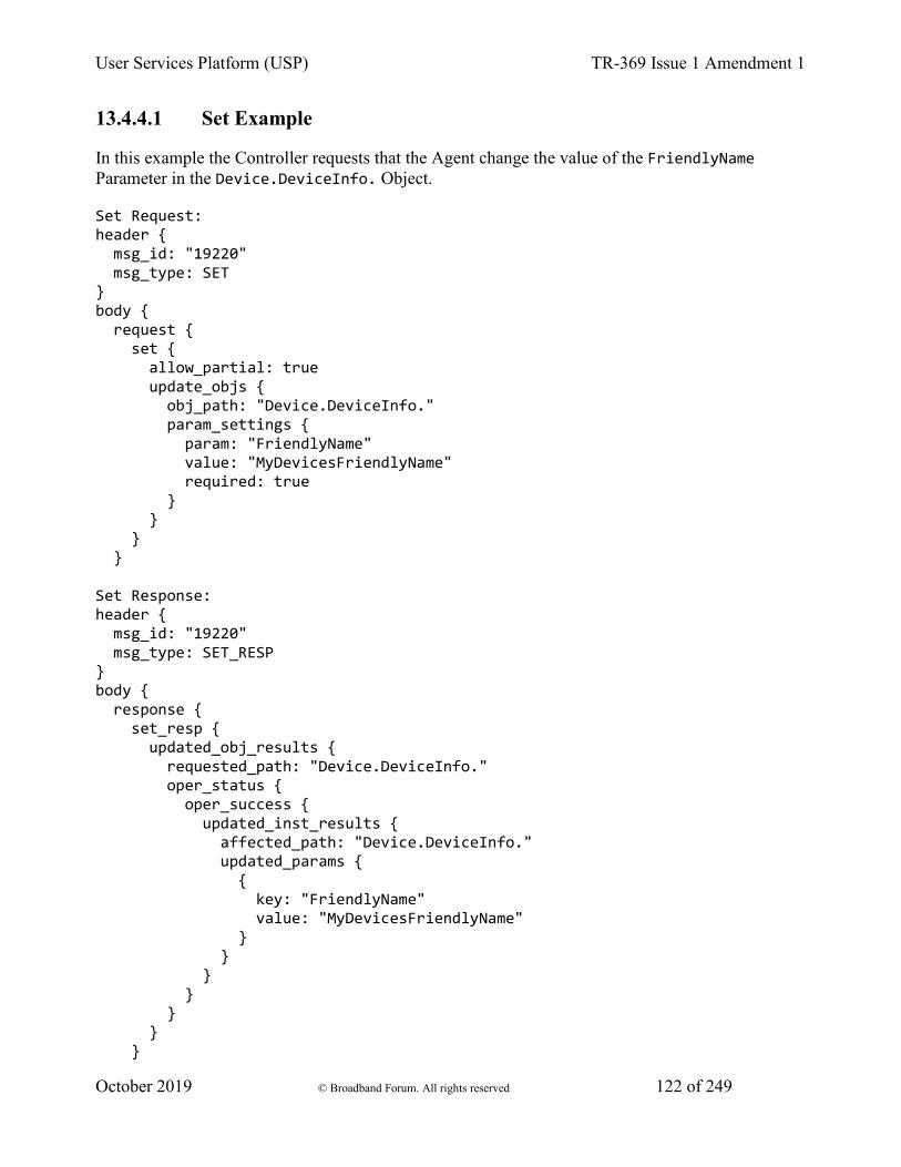
User Services Platform (USP) TR-369 Issue 1 Amendment 1
October 2019 © Broadband Forum. All rights reserved 122 of 249
13.4.4.1 Set Example
In this example the Controller requests that the Agent change the value of the FriendlyName Parameter in the Device.DeviceInfo. Object.
Set Request: header { msg_id: "19220" msg_type: SET } body { request { set { allow_partial: true update_objs { obj_path: "Device.DeviceInfo." param_settings { param: "FriendlyName" value: "MyDevicesFriendlyName" required: true } } } } Set Response: header { msg_id: "19220" msg_type: SET_RESP } body { response { set_resp { updated_obj_results { requested_path: "Device.DeviceInfo." oper_status { oper_success { updated_inst_results { affected_path: "Device.DeviceInfo." updated_params { { key: "FriendlyName" value: "MyDevicesFriendlyName" } } } } } } }
User Services Platform (USP) TR-369 Issue 1 Amendment 1
October 2019 © Broadband Forum. All rights reserved 123 of 249
} }
13.4.4.2 Set Request fields
bool allow_partial
This field tells the Agent how to process the message in the event that one or more of the Objects matched in the obj_path fails to update.
R-SET.0 - If the allow_partial field is set to true, and no other exceptions are encountered, the Agent treats each UpdateObject message obj_path independently. The Agent MUST complete the update of valid Objects regardless of the inability to update one or more Objects (see allow partial and required parameters).
Note: This may cause some counterintuitive behavior if there are no required parameters to be updated. The Set Request can still result in a Set Response (rather than an Error Message) if allow_partial is set to true.
R-SET.1 - If the allow_partial field is set to false, and no other exceptions are encountered, the Agent treats each UpdateObject message obj_path holistically. A failure to update any one Object MUST cause the Set message to fail and return an Error message (see allow partial and required parameters).
repeated UpdateObject update_objs
This field contains a repeated set of UpdateObject messages.
13.4.4.2.1 UpdateObject fields
string obj_path
This field contains an Object Path, Instance Path, or Search Path to Objects or Object Instances in the Agent’s Instantiated Data Model.
repeated UpdateParamSetting param_settings
The field contains a repeated set of UpdatedParamSetting messages.
13.4.4.2.1.1 UpdateParamSetting fields
string param
This field contains the local name of a parameter of the Object specified in obj_path.
string value
User Services Platform (USP) TR-369 Issue 1 Amendment 1
October 2019 © Broadband Forum. All rights reserved 124 of 249
This field contains the value of the parameter specified in the param field that the Controller would like to configure.
bool required
This field specifies whether the Agent should treat the update of the Object specified in obj_path as conditional upon the successful configuration of this parameter.
R-SET.2 - If the required field is set to true, a failure to update this parameter MUST result in a failure to update the Object (see allow partial and required parameters).
13.4.4.3 Set Response
repeated UpdatedObjectResult updated_obj_results
This field contains a repeated set of UpdatedObjectResult messages for each UpdateObject message in the associated Set Request.
13.4.4.3.1 UpdatedObjectResult fields
string requested_path
This field returns the value of updated_obj_results in the UpdateObject message associated with this UpdatedObjectResult.
OperationStatus oper_status
The field contains a message of type OperationStatus that specifies the overall status for the update of the Object specified in requested_path.
13.4.4.3.1.1 OperationStatus fields
oneof oper_status
This field contains a message of one of the following types.
OperationFailure oper_failure
Used when the Object specified in requested_path failed to be updated.
OperationSuccess oper_success
13.4.4.3.1.2 OperationFailure fields
fixed32 err_code
User Services Platform (USP) TR-369 Issue 1 Amendment 1
October 2019 © Broadband Forum. All rights reserved 125 of 249
This field contains a numeric code indicating the type of error that caused the Object update to fail.
string err_msg
This field contains additional information about the reason behind the error.
repeated UpdatedInstanceFailure updated_inst_failures
This field contains a repeated set of messages of type UpdatedInstanceFailure.
13.4.4.3.1.3 UpdatedInstanceFailure fields
string affected_path
This field returns the Object Path or Object Instance Path of the Object that failed to update.
repeated ParameterError param_errs
This field contains a repeated set of ParameterError messages.
13.4.4.3.1.4 ParameterError fields
string param
This field contains the Parameter Path to the parameter that failed to be set.
fixed32 err_code
This field contains the error code of the error that caused the parameter set to fail.
string err_msg
This field contains text related to the error specified by err_code.
13.4.4.3.1.5 OperationSuccess fields
repeated UpdatedInstanceResult updated_inst_results
This field contains a repeated set of UpdatedInstanceResult messages.
13.4.4.3.1.6 UpdatedInstanceResult fields
string affected_path
This field returns the Object Path or Object Instance Path of the updated Object.
User Services Platform (USP) TR-369 Issue 1 Amendment 1
October 2019 © Broadband Forum. All rights reserved 126 of 249
repeated ParameterError param_errs
This field contains a repeated set of ParameterError messages.
map<string, string> updated_params
This field returns a set of key/value pairs containing a path (relative to the affected_path) to each of the updated Object’s parameters, their values, plus sub-Objects and their values that were updated by the Set Request.
R-SET.3 - If the Controller does not have Read permission on any of the parameters specified in updated_params, these parameters MUST NOT be returned in this field.
Note: If the Set Request configured a parameter to the same value it already had, this parameter is still returned in the updated_params.
13.4.4.3.1.7 ParameterError fields
string param
This field contains the Parameter Path to the parameter that failed to be set.
fixed32 err_code
This field contains the error code of the error that caused the parameter set to fail.
string err_msg
This field contains text related to the error specified by err_code.
13.4.4.4 Set Message Supported Error Codes
Appropriate error codes for the Set message include 7000-7016, 7020, 7021, 7026, and 7800-7999.
13.4.5 The Delete Message
The Delete Message is used to remove Instances of Multi-Instance Objects in the Agent’s Instantiated Data Model.
13.4.5.1 Delete Example
In this example, the Controller requests that the Agent remove the instance in Device.LocalAgent.Controller table that has the EndpointID value of “controller-temp”.
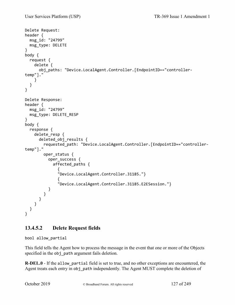
User Services Platform (USP) TR-369 Issue 1 Amendment 1
October 2019 © Broadband Forum. All rights reserved 127 of 249
Delete Request: header { msg_id: "24799" msg_type: DELETE } body { request { delete { obj_paths: "Device.LocalAgent.Controller.[EndpointID=="controller-temp"]." } } } Delete Response: header { msg_id: "24799" msg_type: DELETE_RESP } body { response { delete_resp { deleted_obj_results { requested_path: "Device.LocalAgent.Controller.[EndpointID=="controller-temp"]." oper_status { oper_success { affected_paths { { "Device.LocalAgent.Controller.31185."} { "Device.LocalAgent.Controller.31185.E2ESession."} } } } } } }
13.4.5.2 Delete Request fields
bool allow_partial
This field tells the Agent how to process the message in the event that one or more of the Objects specified in the obj_path argument fails deletion.
R-DEL.0 - If the allow_partial field is set to true, and no other exceptions are encountered, the Agent treats each entry in obj_path independently. The Agent MUST complete the deletion of
User Services Platform (USP) TR-369 Issue 1 Amendment 1
October 2019 © Broadband Forum. All rights reserved 128 of 249
valid Objects regardless of the inability to delete one or more Objects (see allow partial and required parameters).
R-DEL.1 - If the allow_partial field is set to false, and no other exceptions are encountered, the Agent treats each entry in obj_path holistically. A failure to delete any one Object MUST cause the Delete message to fail and return an Error message (see allow partial and required parameters).
repeated string obj_paths
This field contains a repeated set of Object Instance Paths or Search Paths.
13.4.5.3 Delete Response fields
repeated DeletedObjectResult deleted_obj_results
This field contains a repeated set of DeletedObjectResult messages.
13.4.5.3.1 DeletedObjectResult fields
string requested_path
This field returns the value of the entry of obj_paths (in the Delete Request) associated with this DeleteObjectResult.
OperationStatus oper_status
This field contains a message of type OperationStatus.
13.4.5.3.1.1 OperationStatus fields
oneof oper_status
This field contains a message of one of the following types.
OperationFailure oper_failure
Used when the Object specified in requested_path failed to be deleted.
OperationSuccess oper_success
13.4.5.3.1.2 OperationFailure fields
Note: Since the OperationSuccess message of the Delete Response contains an unaffected_path_errs, the OperationStatus will only contain an OperationFailure message

User Services Platform (USP) TR-369 Issue 1 Amendment 1
October 2019 © Broadband Forum. All rights reserved 129 of 249
if the requested_path did not match any existing Objects (error 7016) or was syntactically incorrect (error 7008).
fixed32 err_code
This field contains a numeric code indicating the type of error that caused the delete to fail. A value of 0 indicates the Object was deleted successfully.
string err_msg
This field contains additional information about the reason behind the error.
13.4.5.3.1.3 OperationSuccess fields
repeated string affected_paths
This field returns a repeated set of Path Names to Object Instances.
R-DEL.2 - If the Controller does not have Read permission on any of the Objects specified in affected_paths, these Objects MUST NOT be returned in this field.
R-DEL.2a - If the requested_path was valid (i.e., properly formatted and in the Agent’s supported data model) but did not resolve to any objects in the Agent’s instantiated data model, the Agent MUST return an OperationSuccess for this requested_path, and include an empty set for affected_path.
repeated UnaffectedPathError unaffected_path_errs
This field contains a repeated set of messages of type UnaffectedPathError.
R-DEL.3 - If any of the Object Instances specified in the obj_paths field fail to delete, this set MUST include one UnaffectedPathError message for each of the Object Instances that failed to Delete.
R-DEL.4 - If the Controller does not have Read permission on any of the Objects specified in unaffected_paths, these Objects MUST NOT be returned in this field.
13.4.5.3.1.4 UnaffectedPathError fields
string unaffected_path
This field returns the Path Name to the Object Instance that failed to be deleted.
fixed32 err_code
This field contains the error code of the error that caused the deletion of this object to fail.

User Services Platform (USP) TR-369 Issue 1 Amendment 1
October 2019 © Broadband Forum. All rights reserved 130 of 249
string err_msg
This field contains text related to the error specified by err_code.
13.4.5.4 Delete Message Supported Error Codes
Appropriate error codes for the Delete message include 7000-7008, 7015, 7016, 7018, 7024, 7026 and 7800-7999.
13.5 Reading an Agent’s State and Capabilities
An Agent’s current state and capabilities are represented in its data model. The current state is referred to as its Instantiated Data Model, while the data model that represents its set of capabilities is referred to as its Supported Data Model. Messages exist to retrieve data from both the instantiated and Supported Data Models.
13.5.1 The Get Message
The basic Get message is used to retrieve the values of a set of Object’s parameters in order to learn an Agent’s current state. It takes a set of search paths as an input and returns the complete tree of parameters, plus the parameters of all sub-Objects, of any Object matched by the specified expressions. The search paths specified in a Get request can also target individual parameters within Objects to be returned.
Note: Those familiar with Broadband Forum TR-069 will recognize this behavior as the difference between “partial paths” and “complete paths”. This behavior is replicated in USP for the Get message for each path that is matched by the expression(s) supplied in the request.
Note: Each search path is intended to be evaluated separately, and the results from a given search path are returned in an field dedicated to that path. As such, it is possible that the same information may be returned from more than one search path. This is intended, and the Agent should treat each search path atomically.
The response returns an entry for each Path Name resolved by the path given in requested_path. If a path expression specified in the request does not match any valid parameters or Objects, the response will indicate that this expression was an “invalid path”, indicating that the Object or parameter does not currently exist in the Agent’s Supported Data Model.
For each resolved Path Name, a ResolvedPathResult message is given in the Response. This ResolvedPathResult contains the resolved_path, followed by a list of parameters (result_params) of both the resolved_path Object and all of its sub-objects, plus their values. If there are no parameters, result_params may be empty. These Parameter Paths are Relative Paths to the resolved_path.

User Services Platform (USP) TR-369 Issue 1 Amendment 1
October 2019 © Broadband Forum. All rights reserved 131 of 249
13.5.1.1 Get Examples
For example, a Controller wants to read the data model to learn the settings and stats of a single WiFi SSID, “HomeNetwork” with a BSSID of “00:11:22:33:44:55”. It could use a Get request with the following fields:
Get { param_paths { "Device.WiFi.SSID.[SSID=="Homenetwork"&&BSSID==00:11:22:33:44:55]." } }
In response to this request the Agent returns all parameters, plus sub-Objects and their parameters, of the addressed instance. The Agent returns this data in the Get response using a field for each of the requested paths. In this case:
GetResp { req_path_results { requested_path: "Device.WiFi.SSID.[SSID=="Homenetwork"&&BSSID=00:11:22:33:44:55]." err_code : 0 err_msg : resolved_path_results { resolved_path : "Device.WiFi.SSID.1." result_params { { key: "Enable" value: "True"} { key: "Status" value: "Up"} { key: "Name" value: "Home Network"} { key: "LastChange" value: "864000"} { key: "BSSID" value: "00:11:22:33:44:55"} { key: "Stats.BytesSent" value: "24901567"} { key: "Stats.BytesReceived" value: "892806908296"} (etc.) }
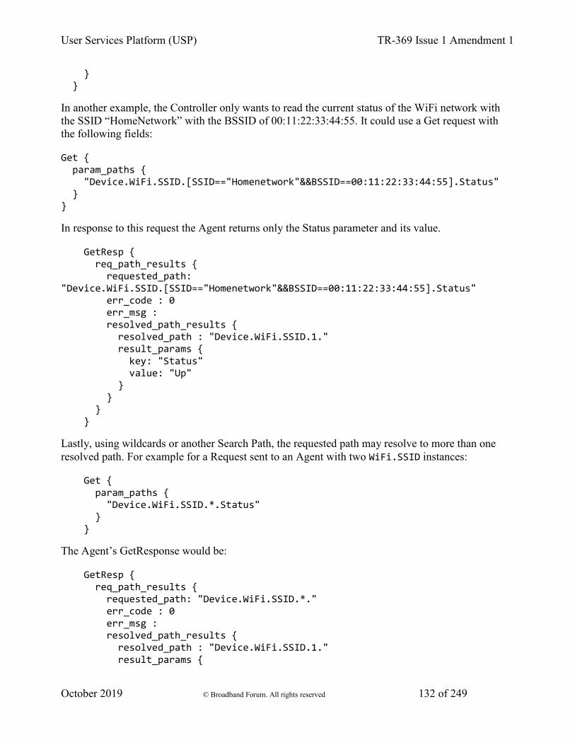
User Services Platform (USP) TR-369 Issue 1 Amendment 1
October 2019 © Broadband Forum. All rights reserved 132 of 249
} }
In another example, the Controller only wants to read the current status of the WiFi network with the SSID “HomeNetwork” with the BSSID of 00:11:22:33:44:55. It could use a Get request with the following fields:
Get { param_paths { "Device.WiFi.SSID.[SSID=="Homenetwork"&&BSSID==00:11:22:33:44:55].Status" } }
In response to this request the Agent returns only the Status parameter and its value.
GetResp { req_path_results { requested_path: "Device.WiFi.SSID.[SSID=="Homenetwork"&&BSSID==00:11:22:33:44:55].Status" err_code : 0 err_msg : resolved_path_results { resolved_path : "Device.WiFi.SSID.1." result_params { key: "Status" value: "Up" } } } }
Lastly, using wildcards or another Search Path, the requested path may resolve to more than one resolved path. For example for a Request sent to an Agent with two WiFi.SSID instances:
Get { param_paths { "Device.WiFi.SSID.*.Status" } }
The Agent’s GetResponse would be:
GetResp { req_path_results { requested_path: "Device.WiFi.SSID.*." err_code : 0 err_msg : resolved_path_results { resolved_path : "Device.WiFi.SSID.1." result_params {
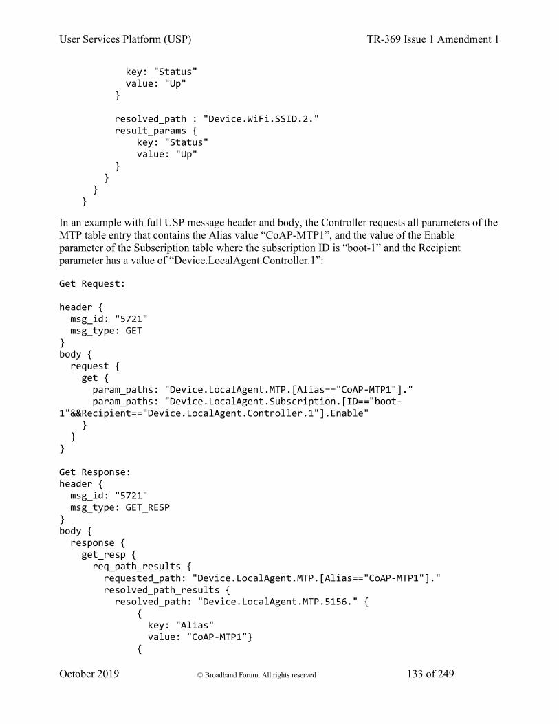
User Services Platform (USP) TR-369 Issue 1 Amendment 1
October 2019 © Broadband Forum. All rights reserved 133 of 249
key: "Status" value: "Up" } resolved_path : "Device.WiFi.SSID.2." result_params { key: "Status" value: "Up" } } } }
In an example with full USP message header and body, the Controller requests all parameters of the MTP table entry that contains the Alias value “CoAP-MTP1”, and the value of the Enable parameter of the Subscription table where the subscription ID is “boot-1” and the Recipient parameter has a value of “Device.LocalAgent.Controller.1”:
Get Request: header { msg_id: "5721" msg_type: GET } body { request { get { param_paths: "Device.LocalAgent.MTP.[Alias=="CoAP-MTP1"]." param_paths: "Device.LocalAgent.Subscription.[ID=="boot-1"&&Recipient=="Device.LocalAgent.Controller.1"].Enable" } } } Get Response: header { msg_id: "5721" msg_type: GET_RESP } body { response { get_resp { req_path_results { requested_path: "Device.LocalAgent.MTP.[Alias=="CoAP-MTP1"]." resolved_path_results { resolved_path: "Device.LocalAgent.MTP.5156." { { key: "Alias" value: "CoAP-MTP1"} {
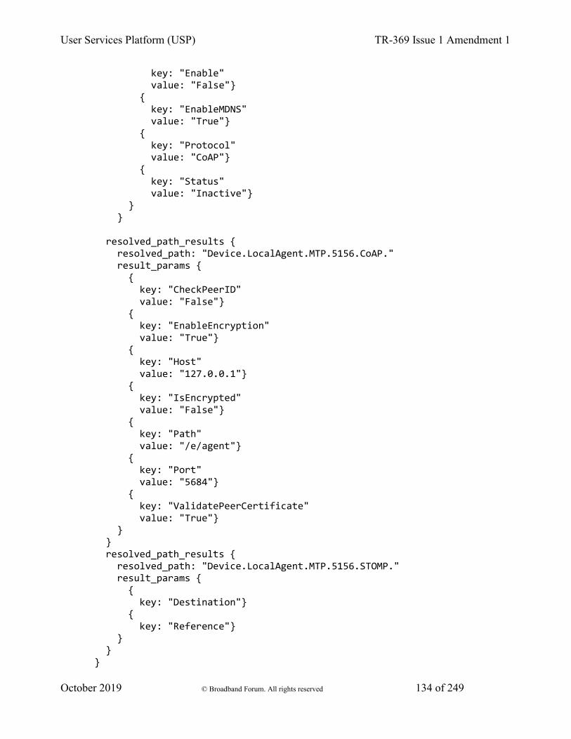
User Services Platform (USP) TR-369 Issue 1 Amendment 1
October 2019 © Broadband Forum. All rights reserved 134 of 249
key: "Enable" value: "False"} { key: "EnableMDNS" value: "True"} { key: "Protocol" value: "CoAP"} { key: "Status" value: "Inactive"} } } resolved_path_results { resolved_path: "Device.LocalAgent.MTP.5156.CoAP." result_params { { key: "CheckPeerID" value: "False"} { key: "EnableEncryption" value: "True"} { key: "Host" value: "127.0.0.1"} { key: "IsEncrypted" value: "False"} { key: "Path" value: "/e/agent"} { key: "Port" value: "5684"} { key: "ValidatePeerCertificate" value: "True"} } } resolved_path_results { resolved_path: "Device.LocalAgent.MTP.5156.STOMP." result_params { { key: "Destination"} { key: "Reference"} } } }
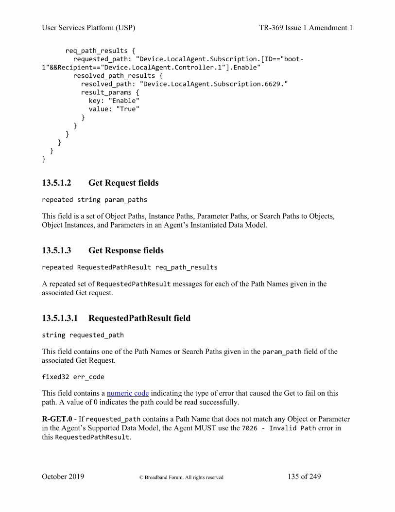
User Services Platform (USP) TR-369 Issue 1 Amendment 1
October 2019 © Broadband Forum. All rights reserved 135 of 249
req_path_results { requested_path: "Device.LocalAgent.Subscription.[ID=="boot-1"&&Recipient=="Device.LocalAgent.Controller.1"].Enable" resolved_path_results { resolved_path: "Device.LocalAgent.Subscription.6629." result_params { key: "Enable" value: "True" } } } } } }
13.5.1.2 Get Request fields
repeated string param_paths
This field is a set of Object Paths, Instance Paths, Parameter Paths, or Search Paths to Objects, Object Instances, and Parameters in an Agent’s Instantiated Data Model.
13.5.1.3 Get Response fields
repeated RequestedPathResult req_path_results
A repeated set of RequestedPathResult messages for each of the Path Names given in the associated Get request.
13.5.1.3.1 RequestedPathResult field
string requested_path
This field contains one of the Path Names or Search Paths given in the param_path field of the associated Get Request.
fixed32 err_code
This field contains a numeric code indicating the type of error that caused the Get to fail on this path. A value of 0 indicates the path could be read successfully.
R-GET.0 - If requested_path contains a Path Name that does not match any Object or Parameter in the Agent’s Supported Data Model, the Agent MUST use the 7026 - Invalid Path error in this RequestedPathResult.
User Services Platform (USP) TR-369 Issue 1 Amendment 1
October 2019 © Broadband Forum. All rights reserved 136 of 249
R-GET.1 - If the Controller making the Request does not have Read permission on an Object or Parameter matched through the requested_path field, the Object or Parameter MUST be treated as if it is not present in the Agent’s Supported data model.
string err_msg
This field contains additional information about the reason behind the error.
repeated ResolvedPathResult resolved_path_results
This field contains one message of type ResolvedPathResult for each path resolved by the Path Name or Search Path given by requested_path.
R-GET.1a - If the requested_path is valid (i.e., properly formatted and in the Agent’s supported data model) but did not resolve to any objects in the Agent’s instantiated data model, the resolved_path_results set MUST be empty and is not considered an error.
13.5.1.3.1.1 ResolvedPathResult fields
string resolved_path
This field contains a Path Name to an Object or Object Instance that was resolved from the Path Name or Search Path given in requested_path.
R-GET.2 - If the requested_path included a Path Name to a Parameter, the resolved_path MUST contain only the Path Name to the parent Object or Object Instance of that parameter.
map<string, string> result_params
This field contains a set of mapped key/value pairs listing a Parameter Path (relative to the Path Name in resolved_path) to each of the parameters and their values, plus sub-objects and their values, of the Object given in resolved_path.
R-GET.3 - If the requested_path included a Path Name to a Parameter, result_params MUST contain only the Parameter included in that path.
R-GET.4 - If the Controller does not have Read permission on any of the parameters specified in result_params, these parameters MUST NOT be returned in this field. This MAY result in this field being empty.
13.5.1.3.1.2 Get Message Supported Error Codes
Appropriate error codes for the Get message include 7000-7006, 7008, 7010, 7026 and 7800-7999.
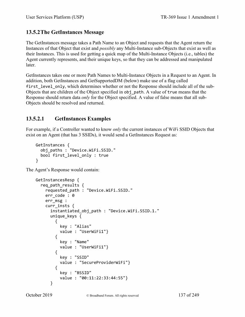
User Services Platform (USP) TR-369 Issue 1 Amendment 1
October 2019 © Broadband Forum. All rights reserved 137 of 249
13.5.2 The GetInstances Message
The GetInstances message takes a Path Name to an Object and requests that the Agent return the Instances of that Object that exist and possibly any Multi-Instance sub-Objects that exist as well as their Instances. This is used for getting a quick map of the Multi-Instance Objects (i.e., tables) the Agent currently represents, and their unique keys, so that they can be addressed and manipulated later.
GetInstances takes one or more Path Names to Multi-Instance Objects in a Request to an Agent. In addition, both GetInstances and GetSupportedDM (below) make use of a flag called first_level_only, which determines whether or not the Response should include all of the sub-Objects that are children of the Object specified in obj_path. A value of true means that the Response should return data only for the Object specified. A value of false means that all sub-Objects should be resolved and returned.
13.5.2.1 GetInstances Examples
For example, if a Controller wanted to know only the current instances of WiFi SSID Objects that exist on an Agent (that has 3 SSIDs), it would send a GetInstances Request as:
GetInstances { obj_paths : "Device.WiFi.SSID." bool first_level_only : true }
The Agent’s Response would contain:
GetInstancesResp { req_path_results { requested_path : "Device.WiFi.SSID." err_code : 0 err_msg : curr_insts { instantiated_obj_path : "Device.WiFi.SSID.1." unique_keys { { key : "Alias" value : "UserWiFi1"} { key : "Name" value : "UserWiFi1"} { key : "SSID" value : "SecureProviderWiFi"} { key : "BSSID" value : "00:11:22:33:44:55"} }
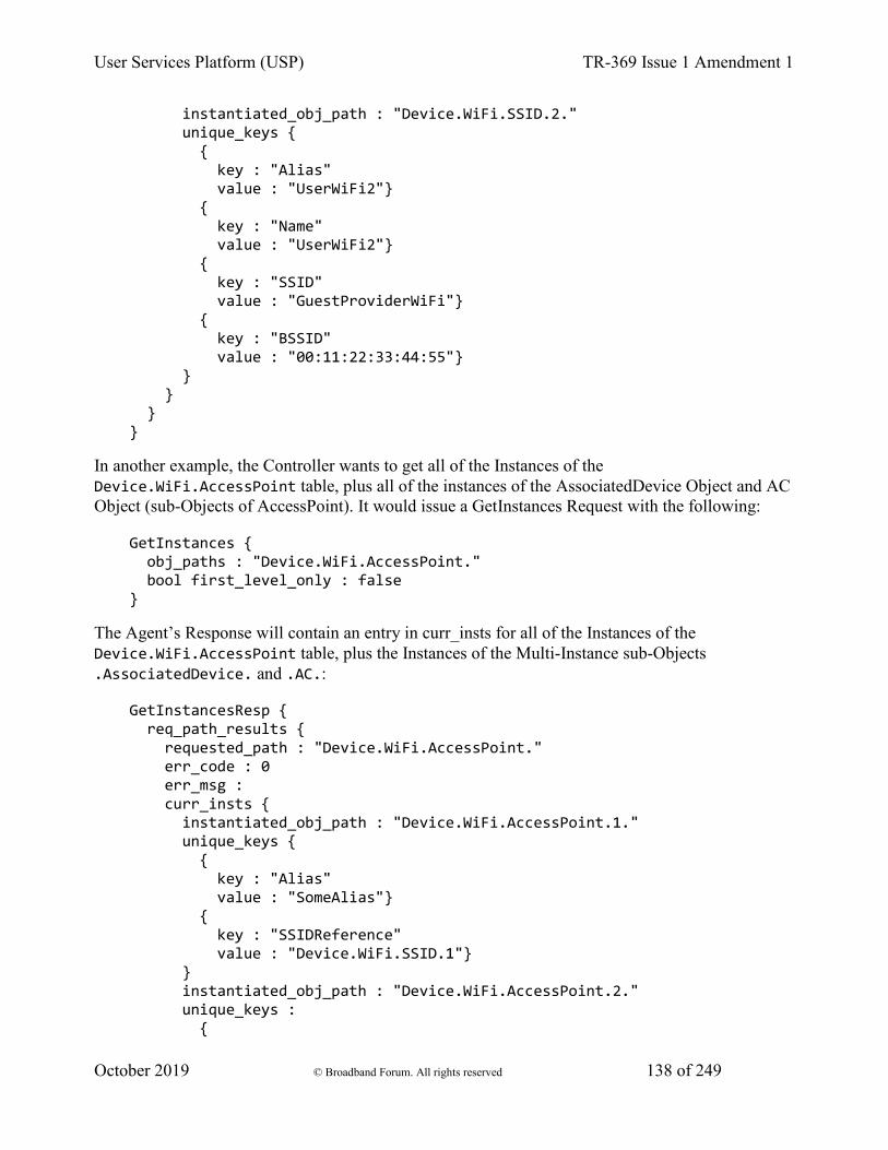
User Services Platform (USP) TR-369 Issue 1 Amendment 1
October 2019 © Broadband Forum. All rights reserved 138 of 249
instantiated_obj_path : "Device.WiFi.SSID.2." unique_keys { { key : "Alias" value : "UserWiFi2"} { key : "Name" value : "UserWiFi2"} { key : "SSID" value : "GuestProviderWiFi"} { key : "BSSID" value : "00:11:22:33:44:55"} } } } }
In another example, the Controller wants to get all of the Instances of the Device.WiFi.AccessPoint table, plus all of the instances of the AssociatedDevice Object and AC Object (sub-Objects of AccessPoint). It would issue a GetInstances Request with the following:
GetInstances { obj_paths : "Device.WiFi.AccessPoint." bool first_level_only : false }
The Agent’s Response will contain an entry in curr_insts for all of the Instances of the Device.WiFi.AccessPoint table, plus the Instances of the Multi-Instance sub-Objects .AssociatedDevice. and .AC.:
GetInstancesResp { req_path_results { requested_path : "Device.WiFi.AccessPoint." err_code : 0 err_msg : curr_insts { instantiated_obj_path : "Device.WiFi.AccessPoint.1." unique_keys { { key : "Alias" value : "SomeAlias"} { key : "SSIDReference" value : "Device.WiFi.SSID.1"} } instantiated_obj_path : "Device.WiFi.AccessPoint.2." unique_keys : {
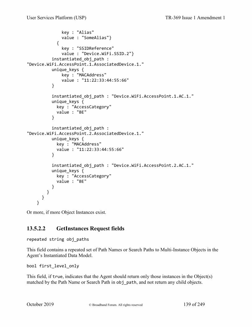
User Services Platform (USP) TR-369 Issue 1 Amendment 1
October 2019 © Broadband Forum. All rights reserved 139 of 249
key : "Alias" value : "SomeAlias"} { key : "SSIDReference" value : "Device.WiFi.SSID.2"} instantiated_obj_path : "Device.WiFi.AccessPoint.1.AssociatedDevice.1." unique_keys { key : "MACAddress" value : "11:22:33:44:55:66" } instantiated_obj_path : "Device.WiFi.AccessPoint.1.AC.1." unique_keys { key : "AccessCategory" value : "BE" } instantiated_obj_path : "Device.WiFi.AccessPoint.2.AssociatedDevice.1." unique_keys { key : "MACAddress" value : "11:22:33:44:55:66" } instantiated_obj_path : "Device.WiFi.AccessPoint.2.AC.1." unique_keys { key : "AccessCategory" value : "BE" } } } }
Or more, if more Object Instances exist.
13.5.2.2 GetInstances Request fields
repeated string obj_paths
This field contains a repeated set of Path Names or Search Paths to Multi-Instance Objects in the Agent’s Instantiated Data Model.
bool first_level_only
This field, if true, indicates that the Agent should return only those instances in the Object(s) matched by the Path Name or Search Path in obj_path, and not return any child objects.
User Services Platform (USP) TR-369 Issue 1 Amendment 1
October 2019 © Broadband Forum. All rights reserved 140 of 249
13.5.2.3 GetInstances Response fields
repeated RequestedPathResult req_path_results
This field contains a RequestedPathResult message for each Path Name or Search
string requested_path
This field contains one of the Path Names or Search Paths given in obj_path of the associated GetInstances Request.
fixed32 err_code
This field contains a numeric code indicating the type of error that caused the Get to fail on this path. A value of 0 indicates the path could be read successfully.
R-GIN.0 - If the Controller making the Request does not have Read permission on an Object or Parameter matched through the requested_path field, the Object or Parameter MUST be treated as if it is not present in the Agent’s Supported Data Model.
string err_msg
This field contains additional information about the reason behind the error.
repeated CurrInstance curr_insts
This field contains a message of type CurrInstance for each Instance of all of the Objects matched by requested_path that exists in the Agent’s Instantiated Data Model.
13.5.2.3.1.1 CurrInstance fields
string instantiated_obj_path
This field contains the Instance Path Name of the Object Instance.
map<string, string> unique_keys
This field contains a map of key/value pairs for all supported parameters that are part of any of this Object’s unique keys.
R-GIN.1 - If the Controller does not have Read permission on any of the parameters specified in unique_keys, these parameters MUST NOT be returned in this field.
13.5.2.4 GetInstances Error Codes
Appropriate error codes for the GetInstances message include 7000-7006, 7008, 7016, 7018, 7026 and 7800-7999.
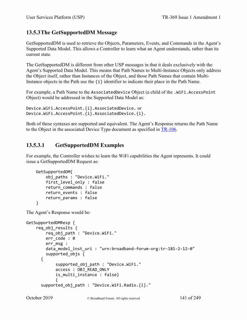
User Services Platform (USP) TR-369 Issue 1 Amendment 1
October 2019 © Broadband Forum. All rights reserved 141 of 249
13.5.3 The GetSupportedDM Message
GetSupportedDM is used to retrieve the Objects, Parameters, Events, and Commands in the Agent’s Supported Data Model. This allows a Controller to learn what an Agent understands, rather than its current state.
The GetSupportedDM is different from other USP messages in that it deals exclusively with the Agent’s Supported Data Model. This means that Path Names to Multi-Instance Objects only address the Object itself, rather than Instances of the Object, and those Path Names that contain Multi-Instance objects in the Path use the {i} identifier to indicate their place in the Path Name.
For example, a Path Name to the AssociatedDevice Object (a child of the .WiFi.AccessPoint Object) would be addressed in the Supported Data Model as:
Device.WiFi.AccessPoint.{i}.AssociatedDevice. or Device.WiFi.AccessPoint.{i}.AssociatedDevice.{i}.
Both of these syntaxes are supported and equivalent. The Agent’s Response returns the Path Name to the Object in the associated Device Type document as specified in TR-106.
13.5.3.1 GetSupportedDM Examples
For example, the Controller wishes to learn the WiFi capabilities the Agent represents. It could issue a GetSupportedDM Request as:
GetSupportedDM{ obj_paths : "Device.WiFi." first_level_only : false return_commands : false return_events : false return_params : false }
The Agent’s Response would be:
GetSupportedDMResp { req_obj_results { req_obj_path : "Device.WiFi." err_code : 0 err_msg : data_model_inst_uri : "urn:broadband-forum-org:tr-181-2-12-0" supported_objs { { supported_obj_path : "Device.WiFi." access : OBJ_READ_ONLY is_multi_instance : false} { supported_obj_path : "Device.WiFi.Radio.{i}."
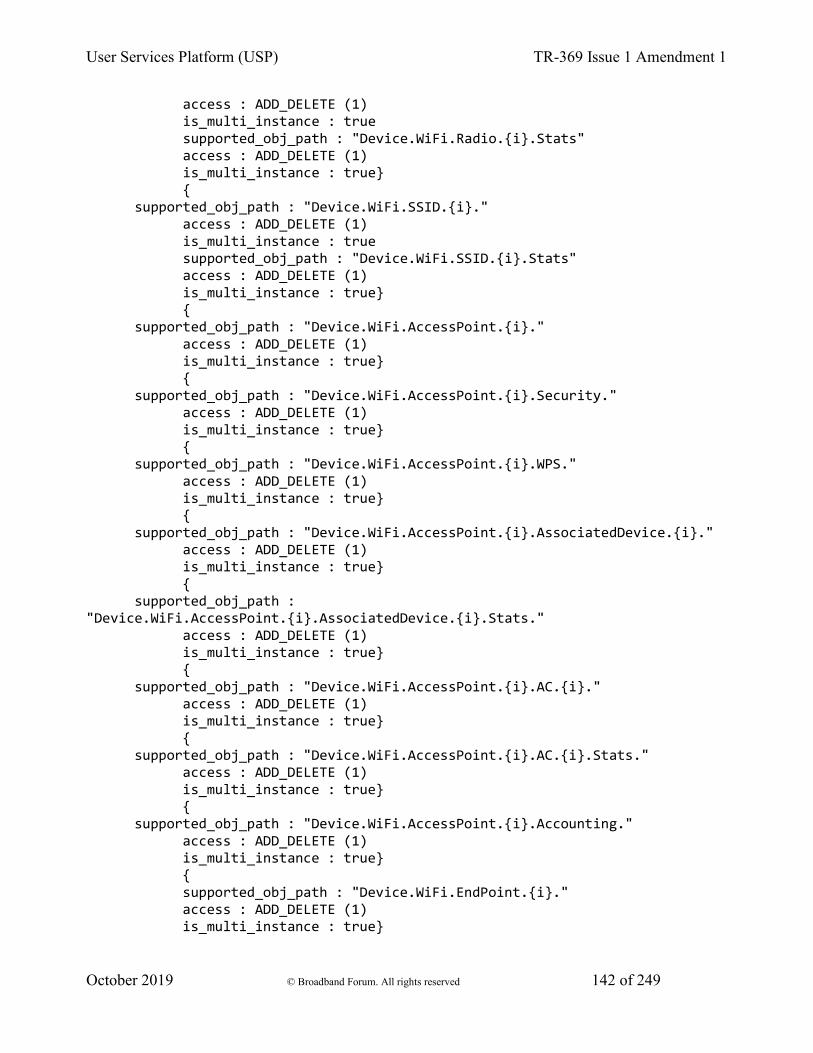
User Services Platform (USP) TR-369 Issue 1 Amendment 1
October 2019 © Broadband Forum. All rights reserved 142 of 249
access : ADD_DELETE (1) is_multi_instance : true supported_obj_path : "Device.WiFi.Radio.{i}.Stats" access : ADD_DELETE (1) is_multi_instance : true} { supported_obj_path : "Device.WiFi.SSID.{i}." access : ADD_DELETE (1) is_multi_instance : true supported_obj_path : "Device.WiFi.SSID.{i}.Stats" access : ADD_DELETE (1) is_multi_instance : true} { supported_obj_path : "Device.WiFi.AccessPoint.{i}." access : ADD_DELETE (1) is_multi_instance : true} { supported_obj_path : "Device.WiFi.AccessPoint.{i}.Security." access : ADD_DELETE (1) is_multi_instance : true} { supported_obj_path : "Device.WiFi.AccessPoint.{i}.WPS." access : ADD_DELETE (1) is_multi_instance : true} { supported_obj_path : "Device.WiFi.AccessPoint.{i}.AssociatedDevice.{i}." access : ADD_DELETE (1) is_multi_instance : true} { supported_obj_path : "Device.WiFi.AccessPoint.{i}.AssociatedDevice.{i}.Stats." access : ADD_DELETE (1) is_multi_instance : true} { supported_obj_path : "Device.WiFi.AccessPoint.{i}.AC.{i}." access : ADD_DELETE (1) is_multi_instance : true} { supported_obj_path : "Device.WiFi.AccessPoint.{i}.AC.{i}.Stats." access : ADD_DELETE (1) is_multi_instance : true} { supported_obj_path : "Device.WiFi.AccessPoint.{i}.Accounting." access : ADD_DELETE (1) is_multi_instance : true} { supported_obj_path : "Device.WiFi.EndPoint.{i}." access : ADD_DELETE (1) is_multi_instance : true}
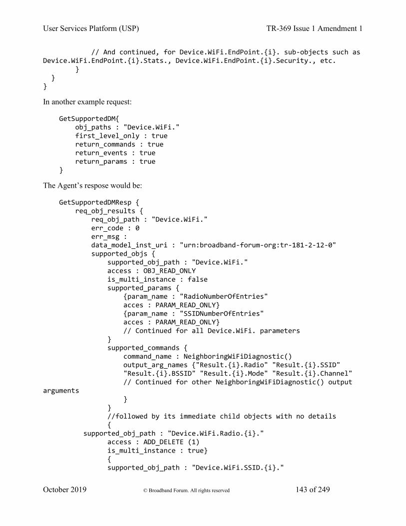
User Services Platform (USP) TR-369 Issue 1 Amendment 1
October 2019 © Broadband Forum. All rights reserved 143 of 249
// And continued, for Device.WiFi.EndPoint.{i}. sub-objects such as Device.WiFi.EndPoint.{i}.Stats., Device.WiFi.EndPoint.{i}.Security., etc. } } }
In another example request:
GetSupportedDM{ obj_paths : "Device.WiFi." first_level_only : true return_commands : true return_events : true return_params : true }
The Agent’s respose would be:
GetSupportedDMResp { req_obj_results { req_obj_path : "Device.WiFi." err_code : 0 err_msg : data_model_inst_uri : "urn:broadband-forum-org:tr-181-2-12-0" supported_objs { supported_obj_path : "Device.WiFi." access : OBJ_READ_ONLY is_multi_instance : false supported_params { {param_name : "RadioNumberOfEntries" acces : PARAM_READ_ONLY} {param_name : "SSIDNumberOfEntries" acces : PARAM_READ_ONLY} // Continued for all Device.WiFi. parameters } supported_commands { command_name : NeighboringWiFiDiagnostic() output_arg_names {"Result.{i}.Radio" "Result.{i}.SSID" "Result.{i}.BSSID" "Result.{i}.Mode" "Result.{i}.Channel" // Continued for other NeighboringWiFiDiagnostic() output arguments } } //followed by its immediate child objects with no details { supported_obj_path : "Device.WiFi.Radio.{i}." access : ADD_DELETE (1) is_multi_instance : true} { supported_obj_path : "Device.WiFi.SSID.{i}."
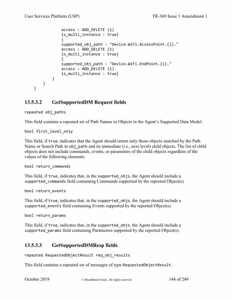
User Services Platform (USP) TR-369 Issue 1 Amendment 1
October 2019 © Broadband Forum. All rights reserved 144 of 249
access : ADD_DELETE (1) is_multi_instance : true} { supported_obj_path : "Device.WiFi.AccessPoint.{i}." access : ADD_DELETE (1) is_multi_instance : true} { supported_obj_path : "Device.WiFi.EndPoint.{i}." access : ADD_DELETE (1) is_multi_instance : true} } } }
13.5.3.2 GetSupportedDM Request fields
repeated obj_paths
This field contains a repeated set of Path Names to Objects in the Agent’s Supported Data Model.
bool first_level_only
This field, if true, indicates that the Agent should return only those objects matched by the Path Name or Search Path in obj_path and its immediate (i.e., next level) child objects. The list of child objects does not include commands, events, or parameters of the child objects regardless of the values of the following elements:
bool return_commands
This field, if true, indicates that, in the supported_objs, the Agent should include a supported_commands field containing Commands supported by the reported Object(s).
bool return_events
This field, if true, indicates that, in the supported_objs, the Agent should include a supported_events field containing Events supported by the reported Object(s).
bool return_params
This field, if true, indicates that, in the supported_objs, the Agent should include a supported_params field containing Parameters supported by the reported Object(s).
13.5.3.3 GetSupportedDMResp fields
repeated RequestedObjectResult req_obj_results
This field contains a repeated set of messages of type RequestedObjectResult.
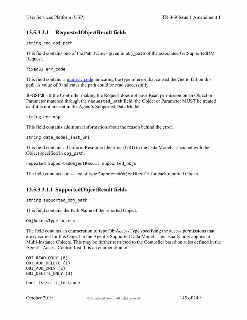
User Services Platform (USP) TR-369 Issue 1 Amendment 1
October 2019 © Broadband Forum. All rights reserved 145 of 249
13.5.3.3.1 RequestedObjectResult fields
string req_obj_path
This field contains one of the Path Names given in obj_path of the associated GetSupportedDM Request.
fixed32 err_code
This field contains a numeric code indicating the type of error that caused the Get to fail on this path. A value of 0 indicates the path could be read successfully.
R-GSP.0 - If the Controller making the Request does not have Read permission on an Object or Parameter matched through the requested_path field, the Object or Parameter MUST be treated as if it is not present in the Agent’s Supported Data Model.
string err_msg
This field contains additional information about the reason behind the error.
string data_model_inst_uri
This field contains a Uniform Resource Identifier (URI) to the Data Model associated with the Object specified in obj_path.
repeated SupportedObjectResult supported_objs
The field contains a message of type SupportedObjectResult for each reported Object.
13.5.3.3.1.1 SupportedObjectResult fields
string supported_obj_path
This field contains the Path Name of the reported Object.
ObjAccessType access
The field contains an enumeration of type ObjAccessType specifying the access permissions that are specified for this Object in the Agent’s Supported Data Model. This usually only applies to Multi-Instance Objects. This may be further restricted to the Controller based on rules defined in the Agent’s Access Control List. It is an enumeration of:
OBJ_READ_ONLY (0) OBJ_ADD_DELETE (1) OBJ_ADD_ONLY (2) OBJ_DELETE_ONLY (3)
bool is_multi_instance
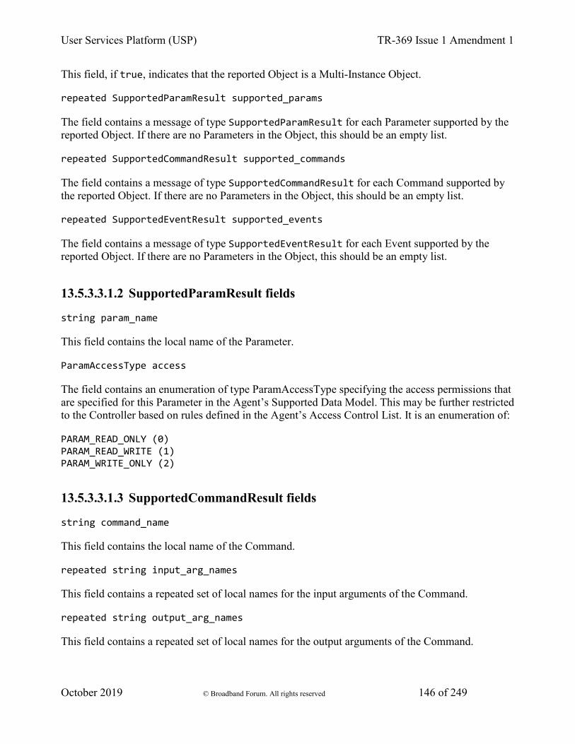
User Services Platform (USP) TR-369 Issue 1 Amendment 1
October 2019 © Broadband Forum. All rights reserved 146 of 249
This field, if true, indicates that the reported Object is a Multi-Instance Object.
repeated SupportedParamResult supported_params
The field contains a message of type SupportedParamResult for each Parameter supported by the reported Object. If there are no Parameters in the Object, this should be an empty list.
repeated SupportedCommandResult supported_commands
The field contains a message of type SupportedCommandResult for each Command supported by the reported Object. If there are no Parameters in the Object, this should be an empty list.
repeated SupportedEventResult supported_events
The field contains a message of type SupportedEventResult for each Event supported by the reported Object. If there are no Parameters in the Object, this should be an empty list.
13.5.3.3.1.2 SupportedParamResult fields
string param_name
This field contains the local name of the Parameter.
ParamAccessType access
The field contains an enumeration of type ParamAccessType specifying the access permissions that are specified for this Parameter in the Agent’s Supported Data Model. This may be further restricted to the Controller based on rules defined in the Agent’s Access Control List. It is an enumeration of:
PARAM_READ_ONLY (0) PARAM_READ_WRITE (1) PARAM_WRITE_ONLY (2)
13.5.3.3.1.3 SupportedCommandResult fields
string command_name
This field contains the local name of the Command.
repeated string input_arg_names
This field contains a repeated set of local names for the input arguments of the Command.
repeated string output_arg_names
This field contains a repeated set of local names for the output arguments of the Command.
User Services Platform (USP) TR-369 Issue 1 Amendment 1
October 2019 © Broadband Forum. All rights reserved 147 of 249
13.5.3.3.1.4 SupportedEventResult
string event_name
This field contains the local name of the Event.
repeated string arg_names
This field contains a repeated set of local names for the arguments of the Event.
13.5.3.4 GetSupportedDM Error Codes
Appropriate error codes for the GetSupportedDM message include 7000-7006, 7008, 7016, 7026, and 7800-7999.
Note - when using error 7026 (invalid path), it is important to note that in the context of GetSupportedDM this applies to the Agent’s Supported Data Model.
13.5.4 GetSupportedProtocol
The GetSupportedProtocol message is used as a simple way for the Controller and Agent to learn which versions of USP each supports to aid in interoperability and backwards compatibility.
13.5.4.1 GetSupportedProtocol Request fields
string controller_supported_protocol_versions
A comma separated list of USP Protocol Versions (major.minor) supported by this Controller.
13.5.4.2 GetSupportedProtocolResponse fields
string agent_supported_protocol_versions
A comma separated list of USP Protocol Versions (major.minor) supported by this Agent.
13.6 Notifications and Subscription Mechanism
A Controller can use the Subscription mechanism to subscribe to certain events that occur on the Agent, such as a parameter change, Object removal, wake-up, etc. When such event conditions are met, the Agent sends a Notify message to the Controller.

User Services Platform (USP) TR-369 Issue 1 Amendment 1
October 2019 © Broadband Forum. All rights reserved 148 of 249
13.6.1 Using Subscription Objects
Subscriptions are maintained in instances of the Multi-Instance Subscription Object in the USP data model. The normative requirements for these Objects are described in the data model parameter descriptions for Device.LocalAgent.Subscription.{i}. in Device:2.
R-NOT.0 - The Agent and Controller MUST follow the normative requirements defined in the Device.LocalAgent.Subscription.{i}. Object specified in Device:2.
Note: Those familiar with Broadband Forum TR-069 will recall that a notification for a value change caused by an Auto-Configuration Server (ACS - the CWMP equivalent of a Controller) are not sent to the ACS. Since there is only a single ACS notifying the ACS of value changes it requested is unnecessary. This is not the case in USP: an Agent should follow the behavior specified by a subscription, regardless of the originator of that subscription.
13.6.1.1 ReferenceList Parameter
All subscriptions apply to one or more Objects or parameters in the Agent’s Instantiated Data Model. These are specified as Path Names or Search Paths in the ReferenceList parameter. The ReferenceList parameter may have different meaning depending on the nature of the notification subscribed to.
For example, a Controller wants to be notified when a new WiFi station joins the WiFi network. It uses the Add message to create a subscription Object instance with Device.WiFi.AccessPoint.1.AssociatedDevice. specified in the ReferenceList parameter and ObjectCreation as the NotificationType.
In another example, a Controller wants to be notified whenever an outside source changes the SSID of a WiFi network. It uses the Add message to create a subscription Object instance with Device.WiFi.SSID.1.SSID specified in the ReferenceList and ValueChange as the NotificationType.
13.6.2 Responses to Notifications and Notification Retry
The Notify request contains a flag, send_resp, that specifies whether or not the Controller should send a response message after receiving a Notify request. This is used in tandem with the NotifRetry parameter in the subscription Object - if NotifRetry is true, then the Agent sends its Notify requests with send_resp : true, and the Agent considers the notification delivered when it receives a response from the Controller. If NotifRetry is false, the Agent does not need to use the send_resp flag and should ignore the delivery state of the notification.
If NotifRetry is true, and the Agent does not receive a response from the Controller, it begins retrying using the retry algorithm below. The subscription Object also uses a NotifExpiration parameter to specify when this retry should end if no success is ever achieved.
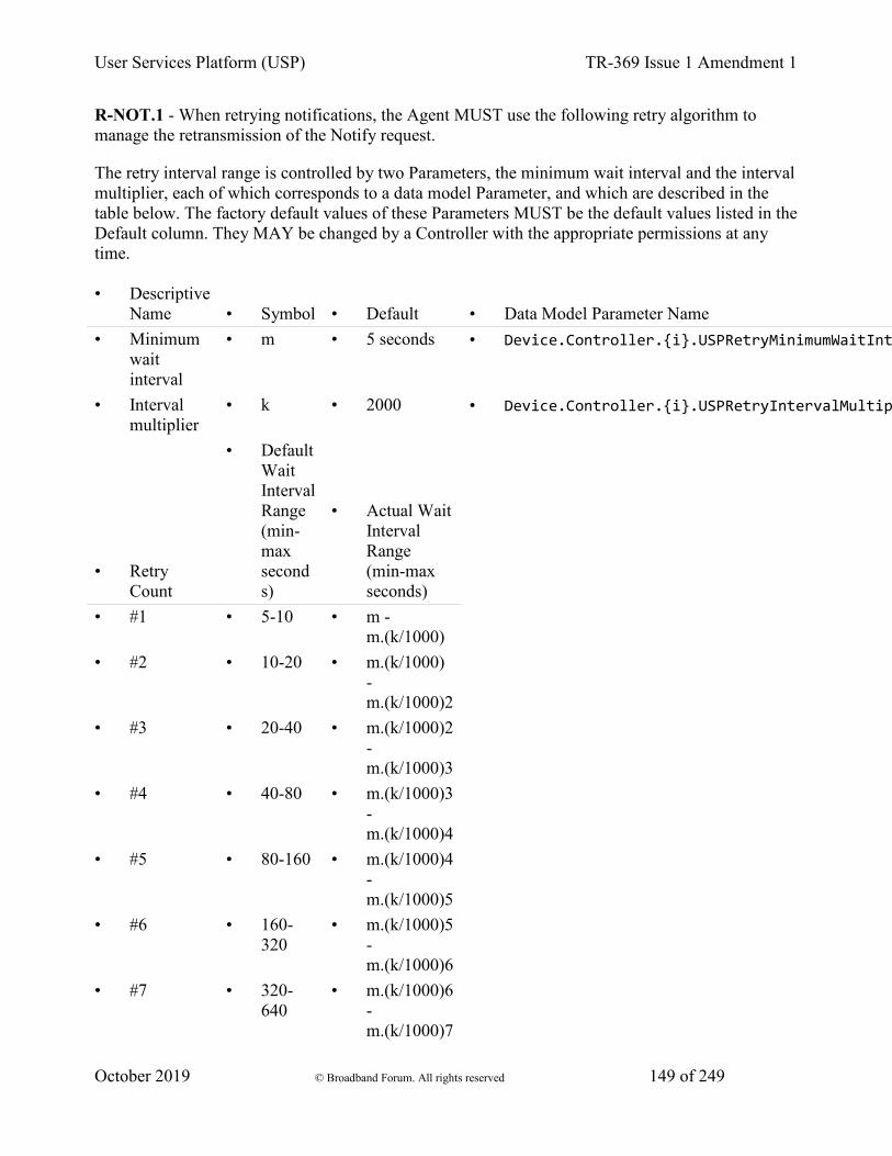
User Services Platform (USP) TR-369 Issue 1 Amendment 1
October 2019 © Broadband Forum. All rights reserved 149 of 249
R-NOT.1 - When retrying notifications, the Agent MUST use the following retry algorithm to manage the retransmission of the Notify request.
The retry interval range is controlled by two Parameters, the minimum wait interval and the interval multiplier, each of which corresponds to a data model Parameter, and which are described in the table below. The factory default values of these Parameters MUST be the default values listed in the Default column. They MAY be changed by a Controller with the appropriate permissions at any time.
• Descriptive Name • Symbol • Default • Data Model Parameter Name
• Minimum wait interval
• m • 5 seconds • Device.Controller.{i}.USPRetryMinimumWaitInt
• Interval multiplier
• k • 2000 • Device.Controller.{i}.USPRetryIntervalMultip
• Retry Count
• Default Wait Interval Range (min-max seconds)
• Actual Wait Interval Range (min-max seconds)
• #1 • 5-10 • m - m.(k/1000)
• #2 • 10-20 • m.(k/1000) - m.(k/1000)2
• #3 • 20-40 • m.(k/1000)2 - m.(k/1000)3
• #4 • 40-80 • m.(k/1000)3 - m.(k/1000)4
• #5 • 80-160 • m.(k/1000)4 - m.(k/1000)5
• #6 • 160-320
• m.(k/1000)5 - m.(k/1000)6
• #7 • 320-640
• m.(k/1000)6 - m.(k/1000)7
User Services Platform (USP) TR-369 Issue 1 Amendment 1
October 2019 © Broadband Forum. All rights reserved 150 of 249
• #8 • 640-1280
• m.(k/1000)7 - m.(k/1000)8
• #9 • 1280-2560
• m.(k/1000)8 - m.(k/1000)9
• #10 and subsequent
• 2560-5120
• m.(k/1000)9 - m.(k/1000)10
R-NOT.2 - Beginning with the tenth retry attempt, the Agent MUST choose from the fixed maximum range. The Agent will continue to retry a failed notification until it is successfully delivered or until the NotifExpiration time is reached.
R-NOT.3 - Once a notification is successfully delivered, the Agent MUST reset the retry count to zero for the next notification message.
R-NOT.4 - If a reboot of the Agent occurs, the Agent MUST reset the retry count to zero for the next notification message.
13.6.3 Notification Types
There are several types events that can cause a Notify request. These include those that deal with changes to the Agent’s Instantiated Data Model (ValueChange, ObjectCreation, ObjectDeletion), the completion of an asynchronous Object-defined operation (OperationComplete), a policy-defined OnBoardRequest, and a generic Event for use with Object-defined events.
13.6.3.1 ValueChange
The ValueChange notification is subscribed to by a Controller when it wants to know that the value of a single or set of parameters has changed from the state it was in at the time of the subscription or to a state as described in an expression, and then each time it transitions from then on for the life of the subscription. It is triggered when the defined change occurs, even if it is caused by the originating Controller.
13.6.3.2 ObjectCreation and ObjectDeletion
These notifications are used for when an instance of the subscribed to Multi-Instance Objects is added or removed from the Agent’s Instantiated Data Model. Like ValueChange, this notification is triggered even if the subscribing Controller is the originator of the creation or deletion.
The ObjectCreation notification also includes the Object’s unique keys and their values as data in the notification.
User Services Platform (USP) TR-369 Issue 1 Amendment 1
October 2019 © Broadband Forum. All rights reserved 151 of 249
13.6.3.3 OperationComplete
The OperationComplete notification is used to indicate that an asynchronous Object-defined operation finished (either successfully or unsuccessfully). These operations may also trigger other Events defined in the data model (see below).
13.6.3.4 OnBoardRequest
An OnBoardRequest notification is used by the Agent when it is triggered by an external source to initiate the request in order to communicate with a Controller that can provide on-boarding procedures and communicate with that Controller (likely for the first time).
R-NOT.5 - An Agent MUST send an OnBoardRequest notify request in the following circumstances:
1. When the SendOnBoardRequest() command is executed. This sends the notification request to the Controller that is the subject of that operation. The SendOnBoardRequest() operation is defined in the Device:2 Data Model. This requirement applies only to those Controller table instances that have their .Enabled parameter set to true.
2. When instructed to do so by internal application policy (for example, when using DHCP discovery defined above).
Note: as defined in the Subscription table, OnBoardRequest is not included as one of the enumerated types of a Subscription, i.e., it is not intended to be the subject of a Subscription.
R-NOT.6 If a response is required, the OnBoardRequest MUST follow the Retry logic defined above.
13.6.3.5 Event
The Event notification is used to indicate that an Object-defined event was triggered on the Agent. These events are defined in the data model and include what parameters, if any, are returned as part of the notification.
13.6.3.6 Notify Examples
In this example, a Controller has subscribed to be notified of changes in value to the Device.DeviceInfo.FriendlyName parameter. When it is changed, the Agent sends a Notify Request to inform the Controller of the change.
Notify Request: header { msg_id: "33936" msg_type: NOTIFY
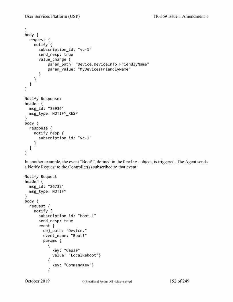
User Services Platform (USP) TR-369 Issue 1 Amendment 1
October 2019 © Broadband Forum. All rights reserved 152 of 249
} body { request { notify { subscription_id: "vc-1" send_resp: true value_change { param_path: "Device.DeviceInfo.FriendlyName" param_value: "MyDevicesFriendlyName" } } } } Notify Response: header { msg_id: "33936" msg_type: NOTIFY_RESP } body { response { notify_resp { subscription_id: "vc-1" } } }
In another example, the event “Boot!”, defined in the Device. object, is triggered. The Agent sends a Notify Request to the Controller(s) subscribed to that event.
Notify Request header { msg_id: "26732" msg_type: NOTIFY } body { request { notify { subscription_id: "boot-1" send_resp: true event { obj_path: "Device." event_name: "Boot!" params { { key: "Cause" value: "LocalReboot"} { key: "CommandKey"} {
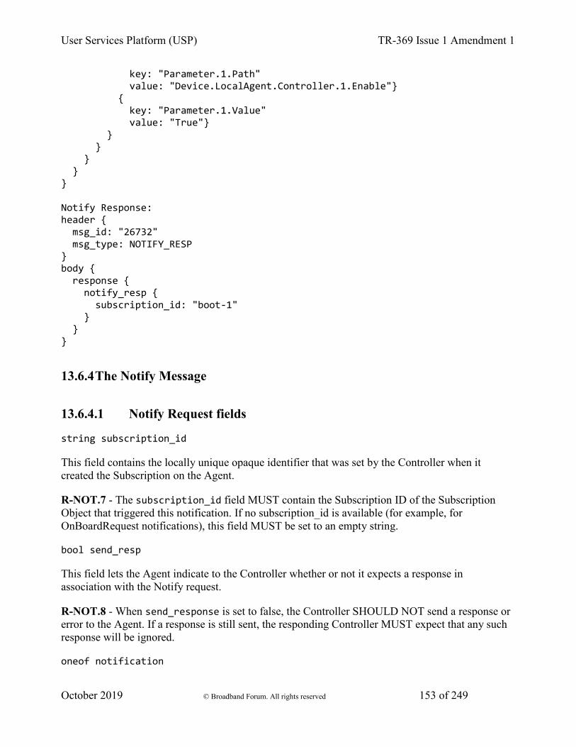
User Services Platform (USP) TR-369 Issue 1 Amendment 1
October 2019 © Broadband Forum. All rights reserved 153 of 249
key: "Parameter.1.Path" value: "Device.LocalAgent.Controller.1.Enable"} { key: "Parameter.1.Value" value: "True"} } } } } } Notify Response: header { msg_id: "26732" msg_type: NOTIFY_RESP } body { response { notify_resp { subscription_id: "boot-1" } } }
13.6.4 The Notify Message
13.6.4.1 Notify Request fields
string subscription_id
This field contains the locally unique opaque identifier that was set by the Controller when it created the Subscription on the Agent.
R-NOT.7 - The subscription_id field MUST contain the Subscription ID of the Subscription Object that triggered this notification. If no subscription_id is available (for example, for OnBoardRequest notifications), this field MUST be set to an empty string.
bool send_resp
This field lets the Agent indicate to the Controller whether or not it expects a response in association with the Notify request.
R-NOT.8 - When send_response is set to false, the Controller SHOULD NOT send a response or error to the Agent. If a response is still sent, the responding Controller MUST expect that any such response will be ignored.
oneof notification
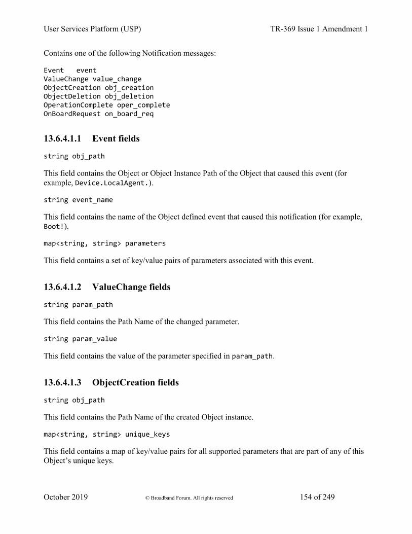
User Services Platform (USP) TR-369 Issue 1 Amendment 1
October 2019 © Broadband Forum. All rights reserved 154 of 249
Contains one of the following Notification messages:
Event event ValueChange value_change ObjectCreation obj_creation ObjectDeletion obj_deletion OperationComplete oper_complete OnBoardRequest on_board_req
13.6.4.1.1 Event fields
string obj_path
This field contains the Object or Object Instance Path of the Object that caused this event (for example, Device.LocalAgent.).
string event_name
This field contains the name of the Object defined event that caused this notification (for example, Boot!).
map<string, string> parameters
This field contains a set of key/value pairs of parameters associated with this event.
13.6.4.1.2 ValueChange fields
string param_path
This field contains the Path Name of the changed parameter.
string param_value
This field contains the value of the parameter specified in param_path.
13.6.4.1.3 ObjectCreation fields
string obj_path
This field contains the Path Name of the created Object instance.
map<string, string> unique_keys
This field contains a map of key/value pairs for all supported parameters that are part of any of this Object’s unique keys.
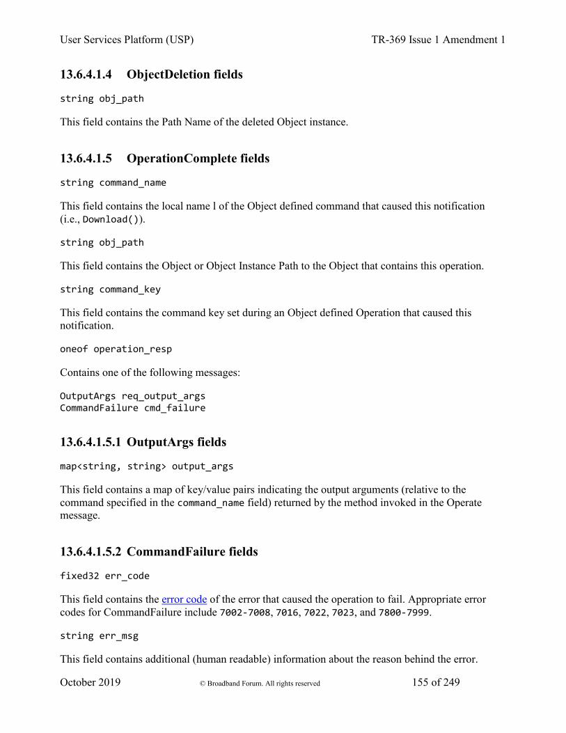
User Services Platform (USP) TR-369 Issue 1 Amendment 1
October 2019 © Broadband Forum. All rights reserved 155 of 249
13.6.4.1.4 ObjectDeletion fields
string obj_path
This field contains the Path Name of the deleted Object instance.
13.6.4.1.5 OperationComplete fields
string command_name
This field contains the local name l of the Object defined command that caused this notification (i.e., Download()).
string obj_path
This field contains the Object or Object Instance Path to the Object that contains this operation.
string command_key
This field contains the command key set during an Object defined Operation that caused this notification.
oneof operation_resp
Contains one of the following messages:
OutputArgs req_output_args CommandFailure cmd_failure
13.6.4.1.5.1 OutputArgs fields
map<string, string> output_args
This field contains a map of key/value pairs indicating the output arguments (relative to the command specified in the command_name field) returned by the method invoked in the Operate message.
13.6.4.1.5.2 CommandFailure fields
fixed32 err_code
This field contains the error code of the error that caused the operation to fail. Appropriate error codes for CommandFailure include 7002-7008, 7016, 7022, 7023, and 7800-7999.
string err_msg
This field contains additional (human readable) information about the reason behind the error.
User Services Platform (USP) TR-369 Issue 1 Amendment 1
October 2019 © Broadband Forum. All rights reserved 156 of 249
13.6.4.1.6 OnBoardRequest fields
string oui
This field contains the Organizationally Unique Identifier associated with the Agent.
string product_class
This field contains a string used to provide additional context about the Agent.
string serial_number
This field contains a string used to provide additional context about the Agent.
string agent_supported_protocol_versions
A comma separated list of USP Protocol Versions (major.minor) supported by this Agent.
13.6.4.2 Notify Response fields
string subscription_id
This field contains the Subscription ID that was received with the Notify Request.
R-NOT.9 - The subscription_id field MUST contain same Subscription ID as was presented in the Notify Request. If the subscription_id field does not match the Subscription ID of the Subscription Object that triggered this notification, this Response MUST be ignored.
13.6.4.3 Notify Error Codes
Appropriate error codes for the Notify message include 7000-7006, and 7800-7999.
13.7 Defined Operations Mechanism
Additional methods (operations) are and can be defined in the USP data model. Operations are generally defined on an Object, using the “command” attribute, as defined in TR-106. The mechanism is controlled using the Operate message in conjunction with the Multi-Instance Request Object.
13.7.1 Synchronous Operations
A synchronous operation is intended to complete immediately following its processing. When complete, the output arguments are sent in the Operate response. If the send_resp flag is false, the Controller doesn’t need the returned information (if any), and the Agent does not send an Operate Response.

User Services Platform (USP) TR-369 Issue 1 Amendment 1
October 2019 © Broadband Forum. All rights reserved 157 of 249
Figure OPR.1 - Operate Message Flow for Synchronous Operations
13.7.2 Asynchronous Operations
An asynchronous operation expects to take some processing on the system the Agent represents and will return results at a later time. When complete, the output arguments are sent in a Notify (OperationComplete) request to any Controllers that have an active subscription to the operation and Object(s) to which it applies.
When a Controller using the Operate request specifies an operation that is defined as asynchronous, the Agent creates an instance of the Request Object in its data model, and includes a reference to the created Object in the Operate response. If the send_resp flag is false, the Controller doesn’t need the Request details, and intends to ignore it.
The lifetime of a Request Object expires when the operation is complete (either by success or failure). An expired Request Object is removed from the Instantiated Data Model.
R-OPR.0 - When an Agent receives an Operate Request that addresses an asynchronous operation, it MUST create a Request Object in the Request table of its Instantiated Data Model (see Device:2). When the Operation is complete (either success or failure), it MUST remove this Object from the Request table.
If any Controller wants a notification that an operation has completed, it creates a Subscription Object with the NotificationType set to OperationComplete and with the ReferenceList parameter including a path to the specified command. The Agent processes this Subscription when the operation completes and sends a Notify message, including the command_key value that the Controller assigned when making the Operate request.
A Controller can cancel a request that is still present in the Agent’s Device.LocalAgent.Request. table by invoking the Device.LocalAgent.Request.{i}.Cancel() command through another Operate message.

User Services Platform (USP) TR-369 Issue 1 Amendment 1
October 2019 © Broadband Forum. All rights reserved 158 of 249
Figure OPR.2 - Operate Message Flow for Asynchronous Operations
13.7.2.1 Persistance of Asynchronous Operations
Synchronous Operations do not persist across a reboot or restart of the Agent or its underlying system. It is expected that Asynchronous Operations do not persist, and a command that is in process when the Agent is rebooted can be expected to be removed from the Request table, and is considered to have failed. If a command is allowed or expected to be retained across a reboot, it will be noted in the command description.
13.7.3 Operate Requests on Multiple Objects
Since the Operate request can take a path expression as a value for the command field, it is possible to invoke the same operation on multiple valid Objects as part of a single Operate request. Responses to requests to Operate on more than one Object are handled using the OperationResult field type, which is returned as a repeated set in the Operate Response. The success or failure of the operation on each Object is handled separately and returned in a different OperationResult entry. For this reason, operation failures are never conveyed in an Error message - in reply to an Operate request, Error is only used when the message itself fails for one or more reasons, rather than the operation invoked.
User Services Platform (USP) TR-369 Issue 1 Amendment 1
October 2019 © Broadband Forum. All rights reserved 159 of 249
Note: This specification does not make any requirement on the order in which commands on multiple objects selected with a path expression are executed.
R-OPR.1 - When processing Operate Requests on multiple Objects, an Agent MUST NOT send an Error message due to a failed operation. It MUST instead include the failure in the cmd_failure field of the Operate response.
R-OPR.2 - For asynchronous operations the Agent MUST create a separate Request Object for each Object and associated operation matched in the command field.
13.7.4 Event Notifications for Operations
When an operation triggers an Event notification, the Agent sends the Event notification for all subscribed recipients as described above.
13.7.5 Concurrent Operations
If an asynchronous operation is triggered multiple times by one or more Controllers, the Agent has the following options:
1. Deny the new operation (with, for example, 7005 Resources Exceeded )
2. The operations are performed in parallel and independently.
3. The operations are queued and completed in order.
R-OPR.3 - When handling concurrently invoked operations, an Agent MUST NOT cancel an operation already in progress unless explicitly told to do so by a Controller with permission to do so (i.e., via the Device.LocalAgent.Request.{i}.Cancel() operation).
13.7.6 Operate Examples
In this example, the Controller requests that the Agent initiate the SendOnBoardRequest() operation defined in the Device.LocalAgent.Controller. object.
Operate Request: header { msg_id: "42314" msg_type: OPERATE } body { request { operate { command: "Device.LocalAgent.Controller.[EndpointID=="controller"].SendOnBoardRequest()" command_key: "onboard_command_key"
User Services Platform (USP) TR-369 Issue 1 Amendment 1
October 2019 © Broadband Forum. All rights reserved 160 of 249
send_resp: true } } } Response: header { msg_id: "42314" msg_type: OPERATE_RESP } body { response { operate_resp { operation_results { executed_command: "Device.LocalAgent.Controller.1.SendOnBoardRequest()" } } } }
13.7.7 The Operate Message
13.7.7.1 Operate Request fields
string command
This field contains a Command Path or Search Path to an Object defined Operation in one or more Objects.
string command_key
This field contains a string used as a reference by the Controller to match the operation with notifications.
bool send_resp
This field lets the Controller indicate to Agent whether or not it expects a response in association with the operation request.
R-OPR.4 - When send_resp is set to false, the target Endpoint SHOULD NOT send a response or error to the source Endpoint. If a response is still sent, the responding Endpoint MUST expect that any such response will be ignored.
map<string, string> input_args
This field contains a map of key/value pairs indicating the input arguments (relative to the command path in the command field) to be passed to the method indicated in the command field.

User Services Platform (USP) TR-369 Issue 1 Amendment 1
October 2019 © Broadband Forum. All rights reserved 161 of 249
13.7.7.2 Operate Response fields
repeated OperationResult operation_results
This field contains a repeated set of OperationResult messages.
13.7.7.2.1 OperationResult fields
string executed_command
This field contains a Command Path to the Object defined Operation that is the subject of this OperateResp message.
oneof operate_resp
This field contains a message of one of the following types.
string req_obj_path OutputArgs req_output_args CommandFailure cmd_failure
13.7.7.2.1.1 Using req_obj_path
The req_obj_path field, when used as the operate_resp, contains an Object Instance Path to the Request Object created as a result of this asynchronous operation.
13.7.7.2.1.2 OutputArgs fields
map<string, string> output_args
This field contains a map of key/value pairs indicating the output arguments (relative to the command specified in the command field) returned by the method invoked in the Operate message.
13.7.7.2.1.3 CommandFailure fields
fixed32 err_code
This field contains the error code of the error that caused the operation to fail.
string err_msg
This field contains additional (human readable) information about the reason behind the error.
User Services Platform (USP) TR-369 Issue 1 Amendment 1
October 2019 © Broadband Forum. All rights reserved 162 of 249
13.7.7.3 Operate Message Error Codes
Appropriate error codes for the Operate message include 7000-7008, 7012 7015, 7016, 7022, and 7800-7999.
13.8 Error Codes
USP uses error codes with a range 7000-7999 for both Controller and Agent errors. The errors appropriate for each message (and how they must be implemented) are defined in the message descriptions below.
• Code • Name • Applicability • Description • 7000 • Message
failed • Error
Message • This error indicates a general failure
that is described in an err_msg field. • 7001 • Message not
supported • Error
Message • This error indicates that the attempted
message was not understood by the target endpoint.
• 7002 • Request denied (no reason specified)
• Error Message
• This error indicates that the target endpoint cannot or will not process the message.
• 7003 • Internal error • Error Message
• This error indicates that the message failed due to internal hardware or software reasons.
• 7004 • Invalid arguments
• Error Message
• This error indicates that the message failed due to invalid values in the USP message.
• 7005 • Resources exceeded
• Error Message
• This error indicates that the message failed due to memory or processing limitations on the target endpoint.
• 7006 • Permission denied
• Error Message
• This error indicates that the source endpoint does not have the authorization for this action.
• 7007 • Invalid configuration
• Error Message
• This error indicates that the message failed because processing the message would put the target endpoint in an invalid or unrecoverable state.
• 7008 • Invalid path syntax
• any requested_path
• This error indicates that the Path Name used was not understood by the target endpoint.
• 7009 • Parameter action failed
• Set • This error indicates that the parameter failed to update for a general reason described in an err_msg field.
User Services Platform (USP) TR-369 Issue 1 Amendment 1
October 2019 © Broadband Forum. All rights reserved 163 of 249
• 7010 • Unsupported parameter
• Add, Set • This error indicates that the requested Path Name associated with this ParamError did not match any instantiated parameters.
• 7011 • Invalid type • Add, Set • This error indicates that the requested value was not of the correct data type for the parameter.
• 7012 • Invalid value • Add, Set • This error indicates that the requested value was not within the acceptable values for the parameter.
• 7013 • Attempt to update non-writeable parameter
• Add, Set • This error indicates that the source endpoint attempted to update a parameter that is not defined as a writeable parameter.
• 7014 • Value conflict • Add, Set • This error indicates that the requested value would result in an invalid configuration based on other parameter values.
• 7015 • Operation error
• Add, Set, Delete
• This error indicates a general failure in the creation, update, or deletion of an Object that is described in an err_msg field.
• 7016 • Object does not exist
• Add, Set • This error indicates that the requested Path Name associated with this OperationStatus did not match any instantiated Objects.
• 7017 • Object could not be created
• Add • This error indicates that the operation failed to create an instance of the specified Object.
• 7018 • Object is not a table
• Add • This error indicates that the requested Path Name associated with this OperationStatus is not a Multi-Instance Object.
• 7019 • Attempt to create non-creatable Object
• Add • This error indicates that the source endpoint attempted to create an Object that is not defined as able to be created.
• 7020 • Object could not be updated
• Set • This error indicates that the requested Object in a Set request failed to update.
• 7021 • Required parameter failed
• Add, Set • This error indicates that the request failed on this Object because one or more required parameters failed to
User Services Platform (USP) TR-369 Issue 1 Amendment 1
October 2019 © Broadband Forum. All rights reserved 164 of 249
update. Details on the failed parameters are included in an associated ParamError message.
• 7022 • Command failure
• Operate • This error indicates that an command initiated in an Operate Request failed to complete for one or more reasons explained in the err_msg field.
• 7023 • Command canceled
• Operate • This error indicates that an asynchronous command initiated in an Operate Request failed to complete because it was cancelled using the Cancel() operation.
• 7024 • Delete failure • Delete • This error indicates that this Object Instance failed to be deleted.
• 7025 • Object exists with duplicate key
• Add • This error indicates that an Object tried to be created with a unique keys that already exist, or the unique keys were configured to those that already exist.
• 7026 • Invalid path • Any • This error indicates that the Object or Parameter Path Name specified does not match any Objects or Parameters in the Agent’s Supported Data Model
• 7027 • Invalid Command Arguments
• Operate • This error indicates that an Operate message failed due to invalid or unknown arguments specified in the command.
• 7100-7199
• USP Record error codes
• - • These errors are listed and described in (Message Transfer Protocols)[/specification/mtp/].
• 7800-7999
• Vendor defined error codes
• - • These errors are vendor defined.
13.8.1 Vendor Defined Error Codes
Implementations of USP MAY specify their own error codes for use with Errors and Responses. These codes use the 7800-7999 series. There are no requirements on the content of these errors.
14 Authentication and Authorization 1.
USP contains mechanisms for Authentication and Authorization, and Encryption. Encryption can be provided at the MTP layer, the USP layer, or both. Where Endpoints can determine (through
User Services Platform (USP) TR-369 Issue 1 Amendment 1
October 2019 © Broadband Forum. All rights reserved 165 of 249
Authentication) that the termination points of the MTP and USP messages are the same, MTP encryption is sufficient to provide end-to-end encryption and security. Where the termination points are different (because there is a proxy or other intermediate device between the USP Endpoints), USP layer Secure Message Exchange is required, or the intermediate device must be a trusted part of the end-to-end ecosystem.
14.1 Authentication
Authentication of Controllers is done using X.509 certificates as defined in RFC 5280 and RFC 6818. Authentication of Agents is done either by using X.509 certificates or shared secrets. X.509 certificates, at a minimum, need to be usable for MTP security with TLS or DTLS protocols. It is recommended that Agents implement the ability to encrypt all MTPs using one of these two protocols, enable it by default, and not implement the ability to disable it.
In order to support various authentication models (e.g., trust Endpoint identity and associated certificate on first use; precise Endpoint identity is indicated in a certificate issued by a trusted Certificate Authority; trust that MTP connection is being made to a member of a trusted domain as verified by a trusted Certificate Authority (CA)), this specification provides guidance based on conditions under which the Endpoint is operating, and on the Endpoint’s policy for storing certificates of other Endpoints or certificates of trusted CAs. The Device.LocalAgent.Certificate object can be implemented if choosing to expose these stored certificates through the data model. See the Theory of Operations, Certificate Management subsection, below for additional information.
R-SEC.0 - Prior to processing a USP Message from a Controller, the Agent MUST either:
• have the Controller’s certificate information and have a cryptographically protected connection between the two Endpoints, or
• have a Trusted Broker’s certificate information and have a cryptographically protected connection between the Agent and the Trusted Broker
TLS and DTLS both have handshake mechanisms that allow for exchange of certificate information. If the MTP connection is between the Agent and Controller (for example, without going through any application-layer proxy or other intermediate application-layer middle-box), then a secure MTP connection will be sufficient to ensure end-to-end protection, and the USP Record can use payload_security “PLAINTEXT” encoding of the Message. If the middle-box is part of a trusted end-to-end ecosystem, the MTP connection may also be considered sufficient. Otherwise, the USP Record will use Secure Message Exchange.
Whether a Controller requires Agent certificates is left up to the Controller implementation.
14.2 Role Based Access Control (RBAC)
It is expected that Agents will have some sort of Access Control List (ACL) that will define different levels of authorization for interacting with the Agent’s data model. This Working Text
User Services Platform (USP) TR-369 Issue 1 Amendment 1
October 2019 © Broadband Forum. All rights reserved 166 of 249
refers to different levels of authorization as “Roles”. The Agent may be so simple as to only support a single Role that gives full access to its data model; or it may have just an “untrusted” Role and a “full access” Role. Or it may be significantly more complex with, for example, “untrusted” Role, different Roles for parents and children in a customer household, and a different Role for the service provider Controller. These Roles may be fully defined in the Agent’s code, or Role definition may be allowed via the data model.
R-SEC.1 - An Agent MUST confirm a Controller has the necessary permissions to perform the requested actions in a Message prior to performing that action.
R-SEC.1a - Agents SHOULD implement the Controller object with the AssignedRole parameter (with at least read-only data model definition) and InheritedRole parameter (if allowed Roles can come from a trusted CA), so users can see what Controllers have access to the Agent and their permissions. This will help users identify rogue Controllers that may have gained access to the Agent.
See the Theory of Operations, Roles (Access Control) and Assigning Controller Roles subsections, below for additional information on data model elements that can be implemented to expose information and allow control of Role definition and assignment.
14.3 Trusted Certificate Authorities
An Endpoint can have a configured list of trusted Certificate Authority (CA) certificates. The Agent policy may trust the CA to authorize authenticated Controllers to have a specific default Role, or the policy may only trust the CA to authenticate the Controller identity. The Controller policy may require an Agent certificate to be signed by a trusted CA before the Controller exchanges USP Messages with the Agent.
R-SEC.2 - To confirm a certificate was signed by a trusted CA, the Endpoint MUST contain information from one or more trusted CA certificates that are either pre-loaded in the Endpoint or provided to the Endpoint by a secure means. At a minimum, this stored information will include a certificate fingerprint and fingerprint algorithm used to generate the fingerprint. The stored information MAY be the entire certificate.
This secure means can be accomplished through USP (see Theory of Operations, Certificate Management subsection, making use of the Device.LocalAgent.Certificate object), or through a mechanism external to USP. The stored CA certificates can be root or intermediate CAs.
R-SEC.3 - Where a CA is trusted to authenticate Controller identity, the Agent MUST ensure the URN form of the Controller Endpoint ID is in the Controller certificate subjectaltName with a type uniformResourceIdentifier attribute, and this matches the USP Record from_id.
R-SEC.4 - Where a CA is trusted to authorize a Controller Role, the Agent MUST ensure the URN form of the Controller Endpoint ID (that matches the USP Record from_id) is in the Controller certificate subjectaltName with a type uniformResourceIdentifier attribute.
User Services Platform (USP) TR-369 Issue 1 Amendment 1
October 2019 © Broadband Forum. All rights reserved 167 of 249
Note that trusting a CA to authorize a Controller Role requires the Agent to maintain an association between a CA certificate and the Role(s) that CA is trusted to authorize. If the Agent allows CAs to authorize Roles, the Agent will need to identify specific CA certificates in a Controller’s chain of trust that can authorize Roles. The specific Role(s) associated with such a CA certificate can then be inherited by the Controller. The Device.LocalAgent.ControllerTrust.Credential object can be implemented to expose and allow control over trust and authorization of CAs.
Note that if an Agent supports and has enabled a Trust on First Use (TOFU) policy, it is possible for Controllers signed by unknown CAs to be granted the “untrusted role”. See Figures SEC.4 and SEC.5 and the penultimate bullet in the Assigning Controller Roles section below for more information related to TOFU and the “untrusted” role.
14.4 Trusted Brokers
An Endpoint can have a configured list of Trusted Broker certificates. The Endpoint policy would be to trust the broker to vouch for the identity of Endpoints it brokers – effectively authenticating the from_id contained in a received USP Record. The Agent policy may trust the broker to authorize all Controllers whose Records transit the broker to have a specific default Role.
R-SEC.4a - To confirm a certificate belongs to a Trusted Broker, the Endpoint MUST contain information from one or more Trusted Broker certificates that are either pre-loaded in the Endpoint or provided to the Endpoint by a secure means. This stored information MUST be sufficient to determine if a presented certificate is the Trusted Broker certificate.
This secure means of loading certificate information into an Agent can be accomplished through USP (see Theory of Operations section related to Certificate Management), or through a mechanism external to USP.
Note that trusting a broker to authorize a Controller Role requires the Agent to maintain an association between a Trusted Broker certificate and the Role(s) that Trusted Broker is trusted to authorize. The Device.LocalAgent.ControllerTrust.Credential object can be implemented to expose and allow control over identifying Trusted Brokers. The AllowedUses parameter is used to indicate whether an entry is a Trusted Broker.
14.5 Self-Signed Certificates
R-SEC.5 - An Endpoint that generates a self-signed certificate MUST place the URN form of its Endpoint ID in a certificate subjectaltName with a type uniformResourceIdentifier attribute.
Self-signed certificates supplied by Controllers can only be meaningfully used in cases where a person is in a position to provide Authorization (what Role the Controller is trusted to have). Whether or not an Agent allows self-signed certificates from a Controller is a matter of Agent policy.
R-SEC.6 - If an Agent allows Controllers to provide self-signed certificates, the Agent MUST assign such Controllers an “untrusted” Role on first use.
User Services Platform (USP) TR-369 Issue 1 Amendment 1
October 2019 © Broadband Forum. All rights reserved 168 of 249
That is, the Agent will trust the certificate for purpose of encryption, but will heavily restrict what the Controller is authorized to do. See Figures SEC.4 and SEC.5 and the penultimate bullet in the Assigning Controller Roles section below for more information related to TOFU and the “untrusted” role.
R-SEC.7 - If an Agent allows Controllers to provide self-signed certificates, the Agent MUST have a means of allowing an external entity to change the Role of each such Controller.
Controller policy related to trust of Agent self-signed certificates is left to the Controller. Controllers may be designed to refuse self-signed certificates (thereby refusing to control the Agent), they may have a means of allowing a person to approve controlling the Agent via the Controller, or they may automatically accept the Agent.
R-SEC.8 - An Endpoint that accepts self-signed certificates MUST maintain the association of accepted certificate and Endpoint IDs.
Self-signed certificates require a “trust on first use” (TOFU) policy when using them to authenticate an Endpoint’s identity. An external entity (a trusted Controller or user) can then authorize the authenticated Endpoint to have certain permissions. Subsequent to the first use, this same self-signed certificate can be trusted to establish the identity of that Endpoint. However, authentication of the Endpoint can only be subsequently trusted if the association of certificate to identity is remembered (i.e., it is known this is the same certificate that was used previously by that Endpoint). If it is not remembered, then every use is effectively a first use and would need to rely on an external entity to authorize permissions every time. The Device.LocalAgent.Certificate object can be implemented if choosing to expose and allow control of remembered certificates in the data model.
14.6 Agent Authentication
R-SEC.9 - Controllers MUST authenticate Agents either through X.509 certificates, a shared secret, or by trusting a Trusted Broker to vouch for Agent identity.
When authentication is done using X.509 certificates, it is up to Controller policy whether to allow for Agents with self-signed certificates or to require Agent certificates be signed by a CA.
Note that allowing use of, method for transmitting, and procedure for handling shared secrets is specific to the MTP used, as described in Message Transfer Protocols. Shared secrets that are not unique per device are not recommended as they leave devices highly vulnerable to various attacks – especially devices exposed to the Internet.
R-SEC.10 - An Agent certificate MUST contain the URN form of the Agent Endpoint ID in the subjectaltName with a type uniformResourceIdentifier attribute.
R-SEC.10a - The certificate subjectaltName value MUST be used to authenticate the USP Record from_id for any Records secured with an Agent certificate.
User Services Platform (USP) TR-369 Issue 1 Amendment 1
October 2019 © Broadband Forum. All rights reserved 169 of 249
Agent certificates can be used to secure Records by encrypting at the MTP layer Message Transfer Protocols enryption and/or encrypting at the USP layer Secure Message Exchange.
Some Controller implementations may allow multiple Agents to share a single certificate with a wildcarded Endpoint ID.
R-SEC.11 - If a single certificate is shared among multiple Agents, those Agents MUST include a wild-carded instance-id in the Endpoint ID in the subjectaltName with identical authority-scheme and authority-id.
Use of a shared certificate is not recommended, and which portion of the instance-id can be wildcarded may be specific to the authorizing CA or to the authority-id and authority-scheme values of the Endpoint ID. Wildcards can only be allowed in cases where the assigning entity is explicitly identified. Controllers are not required to support wildcarded certificates.
R-SEC.12 - If a wildcard character is present in the instance-id of an Endpoint ID in a certificate subjectaltName, the authority-scheme MUST be one of “oui”, “cid”, “pen”, “os”, or “ops”. In the case of “os” and “ops”, the portion of the instance-id that identifies the assigning entity MUST NOT be wildcarded.
14.7 Challenge Strings and Images
It is possible for the Agent to allow an external entity to change a Controller Role by means of a Challenge string or image. This Challenge string or image can take various forms, including having a user supply a passphrase or a PIN. Such a string could be printed on the Agent packaging, or supplied by means of a SMS to a phone number associated with the user account. These Challenge strings or images can be done using USP operations. Independent of how challenges are accomplished, following are some basic requirements related to Challenge strings and images.
R-SEC.13 - The Agent MAY have factory-default Challenge value(s) (strings or images) in its configuration.
R-SEC.14 - A factory-default Challenge value MUST be unique to the Agent. Re-using the same passphrase among multiple Agents is not permitted.
R-SEC.15 - A factory-default Challenge value MUST NOT be derivable from information the Agent communicates about itself using any protocol at any layer.
R-SEC.16 - The Agent MUST limit the number of tries for the Challenge value to be supplied successfully.
R-SEC.17 - The Agent SHOULD have policy to lock out all use of Challenge values for some time, or indefinitely, if the number of tries limit is exceeded.
See the Theory of Operations, Challenges subsection, below for a description of data model elements that need to be implemented and are used when doing challenges through USP operations.

User Services Platform (USP) TR-369 Issue 1 Amendment 1
October 2019 © Broadband Forum. All rights reserved 170 of 249
14.8 Analysis of Controller Certificates
An Agent will analyze Controller certificates to determine if they are valid, are appropriate for authentication of Controllers, and to determine what permissions (Role) a Controller has. The Agent will also determine whether MTP encryption is sufficient to provide end-to-end protection of the Record and Message, or if USP layer Secure Message Exchange is required.
The diagrams in this section use the database symbol to identify where the described information can be represented in the data model, if an implementation chooses to expose this information through the USP protocol.
14.8.1 Receiving a USP Record
R-SEC.19 - An Agent capable of obtaining absolute time SHOULD wait until it has accurate absolute time before contacting a Controller. If an Agent for any reason is unable to obtain absolute time, it can contact the Controller without waiting for accurate absolute time. If an Agent chooses to contact a Controller before it has accurate absolute time (or if it does not support absolute time), it MUST ignore those components of the Controller certificate that involve absolute time, e.g. not-valid-before and not-valid-after certificate restrictions.
R-SEC.20 - An Agent that has obtained accurate absolute time MUST validate those components of the Controller certificate that involve absolute time.
R-SEC.21 – An Agent MUST clear all cached encryption session and Role authorization information when it reboots.
R-SEC.22 - When an Agent receives a USP Record, the Agent MUST execute logic that achieves the same results as in the decision flows from Figures SEC.1 and SEC.2.

User Services Platform (USP) TR-369 Issue 1 Amendment 1
October 2019 © Broadband Forum. All rights reserved 171 of 249
Figure SEC.1 – Receiving a USP Record
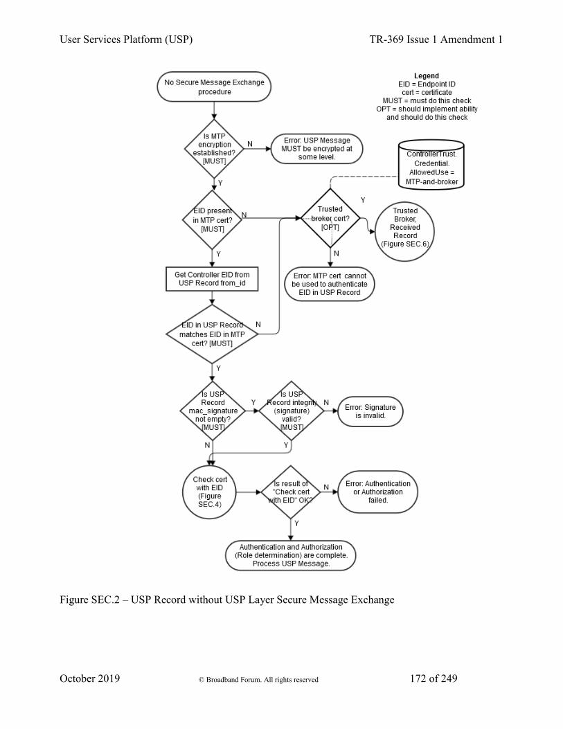
User Services Platform (USP) TR-369 Issue 1 Amendment 1
October 2019 © Broadband Forum. All rights reserved 172 of 249
Figure SEC.2 – USP Record without USP Layer Secure Message Exchange

User Services Platform (USP) TR-369 Issue 1 Amendment 1
October 2019 © Broadband Forum. All rights reserved 173 of 249
14.8.2 Sending a USP Record
R-SEC.23 - When an Agent sends a USP Record, the Agent MUST execute logic that achieves the same results as in the decision flow from Figure SEC.3.
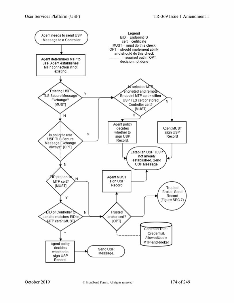
User Services Platform (USP) TR-369 Issue 1 Amendment 1
October 2019 © Broadband Forum. All rights reserved 174 of 249

User Services Platform (USP) TR-369 Issue 1 Amendment 1
October 2019 © Broadband Forum. All rights reserved 175 of 249
Figure SEC.3 – Sending a USP Record
14.8.3 Checking a Certificate Containing an Endpoint ID
R-SEC.24 - When an Agent analyzes a Controller certificate for authentication and determining permissions (Role), the Agent MUST execute logic that achieves the same results as in the decision flows from Figures SEC.4 and SEC.5.
R-SEC.25 - When determining the inherited Role to apply based on Roles associated with a trusted CA, only the first matching CA in the chain will be used.
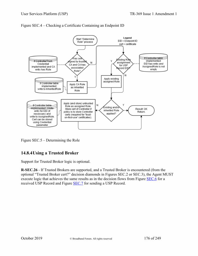
User Services Platform (USP) TR-369 Issue 1 Amendment 1
October 2019 © Broadband Forum. All rights reserved 176 of 249
Figure SEC.4 – Checking a Certificate Containing an Endpoint ID
Figure SEC.5 – Determining the Role
14.8.4 Using a Trusted Broker
Support for Trusted Broker logic is optional.
R-SEC.26 - If Trusted Brokers are supported, and a Trusted Broker is encountered (from the optional “Trusted Broker cert?” decision diamonds in Figures SEC.2 or SEC.3), the Agent MUST execute logic that achieves the same results as in the decision flows from Figure SEC.6 for a received USP Record and Figure SEC.7 for sending a USP Record.

User Services Platform (USP) TR-369 Issue 1 Amendment 1
October 2019 © Broadband Forum. All rights reserved 177 of 249
Figure SEC.6 - Trusted Broker with Received Record
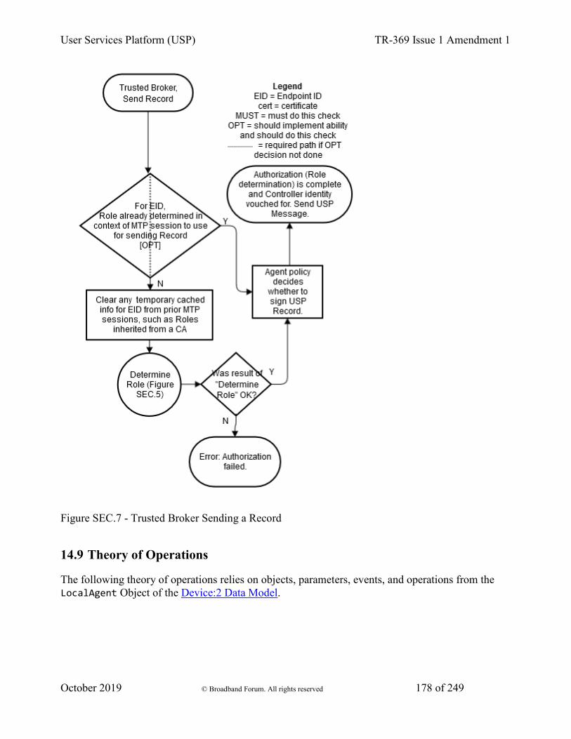
User Services Platform (USP) TR-369 Issue 1 Amendment 1
October 2019 © Broadband Forum. All rights reserved 178 of 249
Figure SEC.7 - Trusted Broker Sending a Record
14.9 Theory of Operations
The following theory of operations relies on objects, parameters, events, and operations from the LocalAgent Object of the Device:2 Data Model.

User Services Platform (USP) TR-369 Issue 1 Amendment 1
October 2019 © Broadband Forum. All rights reserved 179 of 249
14.9.1 Data Model Elements
These data model elements play a role in reporting on and allowing control of trusted Controllers and the permissions they have to read and write parts of the Agent’s data model, and allowing an Agent to establish trust with a Controller.
• LocalAgent.Controller.{i}.AssignedRole parameter
• LocalAgent.Controller.{i}.InheritedRole parameter
• LocalAgent.Controller.{i}.Credential parameter
From component ControllerTrust:
• Object LocalAgent.ControllerTrust.
• Parameters UntrustedRole, BannedRole, TOFUAllowed, TOFUInactivityTimer
• Commands RequestChallenge(), ChallengeResponse()
• Object LocalAgent.ControllerTrust.Role.{i}.
• Object LocalAgent.ControllerTrust.Credential.{i}.
• Object LocalAgent.ControllerTrust.Challenge.{i}.
The Object LocalAgent.Certificate. can be used to manage Controller and CA certificates, along with the LocalAgent.AddCertificate() and LocalAgent.Controller.{i}.AddMyCertificate() commands.
For brevity, Device.LocalAgent is not placed in front of all further object references in this Security section. However, all objects references are under Device.LocalAgent. This section does not describe use of parameters under other top level components.
14.9.2 Roles (Access Control)
Controller permissions are conveyed in the data model through Roles.
14.9.2.1 Role Definition
A Role is described in the data model through use of the ControllerTrust.Role.{i}. object. Each entry in this object identifies the Role it describes, and has a Permission. sub-object for the Targets (data model paths that the related permissions apply to), permissions related to parameters, objects, instantiated objects, and commands identified by the Targets parameter, and the relative Order of precedence among Permission. entries for the Role (the larger value of this parameter takes priority over an entry with a smaller value in the case of overlapping Targets entries for the Role).
User Services Platform (USP) TR-369 Issue 1 Amendment 1
October 2019 © Broadband Forum. All rights reserved 180 of 249
The permissions of a Role for the specified Target entries are described by Param, Obj, InstantiatedObj, and CommandEvent parameters. Each of these is expressed as a string of 4 characters where each character represents a permission (“r” for Read, “w” for Write, “x” for Execute“, and”n" for Notify). The 4 characters are always presented in the same order in the string (rwxn) and the lack of a permission is signified by a “-” character (e.g., r--n). How these permissions are applied to parameters, objects, and various Messages is described in the data model description of these parameters.
An Agent that wants to allow Controllers to define and modify Roles will implement the ControllerTrust.Role.{i}. object with all of the parameters listed in the data model. In order for a Controller to define or modify Role entries, it will need to be assigned a Role that gives it the necessary permission. Care should be taken to avoid defining this Role’s permissions such that an Agent with this Role can modify the Role and no longer make future modifications to the ControllerTrust.Role.{i}. object.
A simple Agent that only wants to inform Controllers of pre-defined Roles (with no ability to modify or define additional Roles) can implement the ControllerTrust.Role. object with read-only data model definition for all entries and parameters. A simple Agent could even implement the object with read-only data model definition and just the Alias and Role parameters, and no Permission. sub-object; this could be sufficient in a case where the Role names convey enough information (e.g., there are only two pre-defined Roles named "Untrusted" and "FullAccess").
14.9.2.2 Special Roles
Two special Roles are identified by the UntrustedRole and BannedRole parameters under the ControllerTrust. object. An Agent can expose these parameters with read-only data model implementation if it simply wants to tell Controllers the names of these specific Roles.
The UntrustedRole is the Role the Agent will automatically assign to any Controller that has not been authorized for a different Role. Any Agent that has a means of allowing a Controller’s Role to be changed (by users through a Challenge string, by other Controllers through modification of Controller.{i}.AssignedRole, or through some other external means) and that allows “unknown” Controllers to attach will need to have an “untrusted” Role defined; even if the identity of this Role is not exposed to Controllers through implementation of the UntrustedRole parameter.
The BannedRole (if implemented) is assigned automatically by the Agent to Controllers whose certificates have been revoked. If it is not implemented, the Agent can use the UntrustedRole for this, as well. It is also possible to simply implement policy for treatment of invalid or revoked certificates (e.g., refuse to connect), rather than associate them with a specific Role. This is left to the Agent policy implementation.
14.9.2.3 A Controller’s Role
A Controller’s assigned Roles can be conveyed by the Controller.{i}.AssignedRole parameter. This parameter is a list of all Role values assigned to the Controller through means other than
User Services Platform (USP) TR-369 Issue 1 Amendment 1
October 2019 © Broadband Forum. All rights reserved 181 of 249
ControllerTrust.Credential.{i}.Role. A Controller’s inherited Roles (those inherited from ControllerTrust.Credential.{i}.Role as described in the next section) need to be maintained separately from assigned Roles and can be conveyed by the Controller.{i}.InheritedRole parameter. Where multiple assigned and inherited Roles have overlapping Targets entries, the resulting permission is the union of all assigned and inherited permissions. For example, if two Roles have the same Targets with one Role assigning the Targets Param a value of r--- and the other Role assigning Param a value of ---n, the resulting permission will be r--n. This is done after determining which ControllerTrust.Role.{i}.Permission.{i} entry to apply for each Role for specific Targets, in the case where a Role has overlapping Permission.{i}.Targets entries for the same Role.
For example, Given the following ControllerTrust.Role.{i}. entries:
i=1, Role = "A"; Permission.1.: Targets = "Device.LocalAgent.", Order = 3, Param = "r---" i=1, Role = "A"; Permission.2.: Targets = "Device.LocalAgent.Controller.", Order = 55, Param = "r-xn" i=3, Role = "B"; Permission.1: Targets = "Device.LocalAgent.", Order = 20, Param = "r---" i=3, Role = "B"; Permission.5: Targets = "Device.LocalAgent.Controller.", Order = 78, Param = "----"
and Device.LocalAgent.Controller.1.AssignedRole = “Device.LocalAgent. ControllerTrust.Role.1., Device.LocalAgent. ControllerTrust.Role.3.”
When determining permissions for the Device.LocalAgent.Controller. table, the Agent will first determine that for Role A Permission.2 takes precedence over Permission.1 (55 > 3). For B, Permission.5 takes precedence over Permission.1 (78 > 20). The union of A and B is “r-xn” + “—-” = “r-xn”.
14.9.2.4 Role Associated with a Credential or Challenge
The ControllerTrust.Credential.{i}.Role parameter value is inherited by Controllers whose credentials have been validated using the credentials in the same entry of the ControllerTrust.Credential.{i}. table. Whenever ControllerTrust.Credential.{i}. is used to validate a certificate, the Agent writes the current value of the associated ControllerTrust.Credential.{i}.Role into the Controller.{i}.InheritedRole parameter. For more information on use of this table for assigning Controller Roles and validating credentials, see the sections below.
The ControllerTrust.Challenge.{i}.Role parameter is a Role that is assigned to Controllers that send a successful ChallengeResponse() command. For more information on use of challenges for assigning Controller Roles, see the sections below.
User Services Platform (USP) TR-369 Issue 1 Amendment 1
October 2019 © Broadband Forum. All rights reserved 182 of 249
14.9.3 Assigning Controller Roles
As mentioned above, the Controller.{i}.AssignedRole parameter can be used to expose the Controller’s assigned Role via the data model.
Note: Even if it is not exposed through the data model, the Agent is expected to maintain knowledge of the permissions assigned to each known Controller.
Controllers can be assigned Roles through a variety of methods, depending on the data model elements an Agent implements and the Agent’s coded policy. Note that it is possible for an Agent to maintain trusted CA credentials with associated permissions (as described by the ControllerTrust.Credential.{i}. object) and various default permission definitions (as identified by the UntrustedRole and BannedRole parameters) without exposing these through the data model. If the data is maintained but not exposed, the same methods can still be used.
Figures SEC.4 and SEC.5 in the above Analysis of Controller Certificates section identify points in the decision logic where some of the following calls to data model parameters can be made. The following bullets note when they are identified in one of these figures.
• Another Controller (with appropriate permission) can insert a Controller (including the AssignedRole parameter value) into the Controller.{i}. table, or can modify the AssignedRole parameter of an existing Controller.{i}. entry. The InheritedRole value cannot be modified by another Controller.
• If credentials in an entry in a ControllerTrust.Credential.{i}.Credential parameter with an associated ControllerTrust.Credential.{i}.Role parameter are used to successfully validate the certificate presented by the Controller, the Controller inherits the Role from the associated ControllerTrust.Credential.{i}.Role. The Agent writes this value to the Controller.{i}.InheritedRole parameter. This step is shown in Figure SEC.5.
• A Controller whose associated certificate is revoked by a CA can be assigned the role in BannedRole, if this parameter or policy is implemented. In this case, the value of BannedRole must be the only value in Controller.{i}.AssignedRole (all other entries are removed) and Controller.{i}.InheritedRole must be empty (all entries are removed). This step is shown in Figure SEC.4.In the case of a Controller that has not previously been assigned a Role or who has been assigned the value of UntrustedRole:
• If the Controller’s certificate is validated by credentials in a ControllerTrust.Credential.{i}.Credential parameter but there is no associated ControllerTrust.Credential.{i}.Role parameter (or the value is empty) and Controller.{i}.AssignedRole is empty, then the Controller is assigned the role in UntrustedRole (written to the Controller.{i}.AssignedRole parameter). This step is shown in Figure SEC.5. Note that assigning UntrustedRole means there needs to be some implemented way to elevate the Controller’s Role, either by another Controller manipulating the Role, implementing Challenges, or some non-USP method.
• If the Controller’s certificate is self-signed or is validated by credentials not in ControllerTrust.Credential.{i}., the Agent policy may be to assign the role in

User Services Platform (USP) TR-369 Issue 1 Amendment 1
October 2019 © Broadband Forum. All rights reserved 183 of 249
UntrustedRole. The optional policy decision (whether or not to allow Trust on First Use (TOFU), which can be codified in the data model with the ControllerTrust.TOFUAllowed flag) is shown in Figure SEC.4; Figure SEC.5 shows the Role assignment.
• If the Agent implements the RequestChallenge() and ChallengeResponse() commands, a Controller assigned the role in UntrustedRole can have permission to read one or more ControllerTrust.Challenge.{i}.Alias and Description values and issue the commands. Roles with more extensive permissions can have permission to read additional ControllerTrust.Challenge.{i}.Alias and Description values. A successful Challenge results in the Controller being assigned the associated Role value.
14.9.4 Controller Certificates and Certificate Validation
When an Agent is presented with a Controller’s certificate, the Agent will always attempt to validate the certificate to whatever extent possible. Figures SEC.4 and SEC.5 in Analysis of Controller Certificates identify points in the decision logic where data model parameters can be used to influence policy decisions related to Controller certificate analysis.
Note that it is possible for an Agent to maintain policy of the type described by the UntrustedRole, BannedRole, and the information described by ControllerTrust.Credential.{i}. and Controller.{i}.Credential without exposing these through the data model. If the policy concepts and data are maintained but not exposed, the same methods can still be used. It is also possible for an Agent to have policy that is not described by any defined data model element.
14.9.5 Challenges
An Agent can implement the ability to provide Controllers with challenges via USP, in order to be trusted with certain Roles. It is also possible to use non-USP methods to issue challenges, such as HTTP digest authentication with prompts for login and password.
To use the USP mechanism, the RequestChallenge() and ChallengeResponse() commands and ControllerTrust.Challenge.{i}. object with at least the Alias, Role, and Description parameters needs to be implemented. The functionality implied by the other ControllerTrust.Challenge.{i}. parameters needs to be implemented, but does not have to be exposed through the data model.
A Controller that sends a Get message on Device.ControllerTrust.Challenge.{i}. will receive all entries and parameters that are allowed for its current assigned Role. In the simplest case, this will be a single entry and only Alias and Description will be supplied for that entry. It is important to restrict visibility to all other implemented parameters to highly trusted Roles, if at all.
The Controller can display the value of Description to the user and allow the user to indicate they want to request the described challenge. If multiple entries were returned, the user can be asked to select which challenge they want to request, based on the description. An example of a description might be “Request administrative privileges” or “Request guest privilege”.
User Services Platform (USP) TR-369 Issue 1 Amendment 1
October 2019 © Broadband Forum. All rights reserved 184 of 249
When the user indicates to the Controller which challenge they want, the Controller sends RequestChallenge() with the path name of the Challenge object instance associated with the desired Description. The Agent replies with the associated Instruction, InstructionType, ValueType and an auto-generated ChallengeID. The Controller presents the value of Instruction to the user (in a manner appropriate for InstructionType). Examples of an instruction might be “Enter passphrase printed on bottom of device” or “Enter PIN sent to registered email address”. The user enters a string per the instructions, and the Controller sends this value together with the ChallengeID in ChallengeResponse().
If the returned value matches Value, the Agent gives a successful response - otherwise it returns an unsuccessful response. If successful, the ControllerTrust.Challenge.{i}.Role replaces an UntrustedRole in Controller.{i}.AssignedRole or is appended to any other Controller.{i}.AssignedRole value.
The number of times a ControllerTrust.Challenge.{i}. entry can be consecutively failed (across all Controllers, without intermediate success) is defined by Retries. Once the number of failed consecutive attempts equals Retries, the ControllerTrust.Challenge.{i}. cannot be retried until after LockoutPeriod has expired.
Type values other than Passphrase can be used and defined to trigger custom mechanisms, such as requests for emailed or SMS-provided PINs.
14.9.6 Certificate Management
If an Agent wants to allow certificates associated with Controllers and CAs to be exposed through USP, the Agent can implement the Controller.{i}.Credential and ControllerTrust.Credential.{i}.Credential parameters, which require implementation of the LocalAgent.Certificate. object. Allowing management of these certificates through USP can be accomplished by implementing LocalAgent.AddCertificate(), Controller.{i}.AddMyCertificate() and Certificate.{i}.Delete() commands.
To allow a Controller to check whether the Agent has correct certificates, the Certificate.{i}.GetFingerprint() command can be implemented.
14.9.7 Application of Modified Parameters
It is possible that various parameters related to authentication and authorization may change that would impact cached encrypted sessions and Role permissions for Controllers. Example of such parameters include Controller.{i}.AssignedRole, Controller.{i}.Credential, ControllerTrust.Role. definition of a Role, and ControllerTrust.Credential.{i}.Role.
There is no expectation that an Agent will apply these changes to cached sessions. It is up to the Agent to determine whether or not it will detect these changes and flush cached session information. However, it is expected that a reboot will clear all cached session information.
User Services Platform (USP) TR-369 Issue 1 Amendment 1
October 2019 © Broadband Forum. All rights reserved 185 of 249
15 Annex A - HTTP Bulk Data Collection
Note - This Annex is a translation from the HTTP Bulk Data Collection mechanism specified in Annex A of Broadband Forum TR-157, which was carried over into Amendment 6 of TR-069. The text here has been altered to fit with USP concepts.
This section discusses the Theory of Operation for the collection and transfer of bulk data using USP, HTTP and the BulkData object defined in Device:2, to a Bulk Data Collector utilizing:
• HTTP/HTTPS for the transfer of collected data
• CSV and JSON for the encoding of collected data to be transferred
The Agent configuration that enables the collection of bulk data using HTTP is defined using the BulkData component objects explained here. During this explanation, there will be references to data model objects specific to Device:2; that specification should be used for reference.
15.1 Enabling HTTP/HTTPS Bulk Data Communication
HTTP/HTTPS communication between the Agent and Bulk Data Collector is enabled by configuring the BulkData.Profile object for the HTTP/HTTPS transport protocol adding and configuring a new BulkData.Profile object instance using the Add message. For example:
.BulkData.Profile.1
.BulkData.Profile.1.Enable=true
.BulkData.Profile.1.Protocol = "HTTP"
.BulkData.Profile.1.ReportingInterval = 300
.BulkData.Profile.1.TimeReference = "0001-01-01T00:00:00Z"
.BulkData.Profile.1.HTTP.URL = "https://bdc.acme.com/somedirectory"
.BulkData.Profile.1.HTTP.Username = "username"
.BulkData.Profile.1.HTTP.Password = "password"
.BulkData.Profile.1.HTTP.Method = "POST"
.BulkData.Profile.1.HTTP.UseDateHeader = true
The configuration above defines a profile that transfers data from the Agent to the Bulk Data Collector using secured HTTP. In addition the Agent will provide authentication credentials (username, password) to the Bulk Data Collector, if requested by the Bulk Data Collector. Finally, the Agent establishes a communication session with the Bulk Data Collector every 300 seconds in order to transfer the data defined by the .BulkData.Report. object instance.
Note - When a Bulk Data Collection Profile is either created or updated the Agent performs permission checks against the objects and parameters in existence at the time of the operation, utilizing the permissions assocated with the operating Controller.

User Services Platform (USP) TR-369 Issue 1 Amendment 1
October 2019 © Broadband Forum. All rights reserved 186 of 249
Once the communication session is established between the Agent and Bulk Data Collector the data is transferred from the Agent using the POST HTTP method with a HTTP Date header and no compression.
R-BULK.0 - In many scenarios Agents will utilize “chunked” transfer encoding. As such, the Bulk Data Collector MUST support the HTTP transfer-coding value of “chunked”.
15.1.1 Use of the URI Query Parameters
The HTTP Bulk Data transfer mechanism allows parameters to be used as HTTP URI query parameters. This is useful when Bulk Data Collector utilizes the specific parameters that the Agent reports for processing (e.g., logging, locating directories) without the need for the Bulk Data Collector to parse the data being transferred.
R-BULK.1 - The Agent MUST transmit the device’s Manufacturer OUI, Product Class and Serial Number or the USP Endpoint ID as part of the URI query parameters. The data model parameters are encoded as:
.DeviceInfo.ManufacturerOUI -> oui
.DeviceInfo.ProductClass -> pc
.DeviceInfo.SerialNumber -> sn
.LocalAgent.EndpointID -> eid
As such, the values of the device’s OUI, Serial Number and Product Class are formatted in the HTTP request URI as follows:
POST https://<bulk data collector url>?oui=00256D&pc=Z&sn=Y
If the USP Endpoint ID is used the HTTP request URI is formatted as:
POST https://<bulk data collector url>?eid=os::000256:asdfa99384
Note - If the USP Endpoint ID should be transmitted together with the device’s Manufacturer OUI, Product Class and Serial Number (e.g. to distinguish multiple bulk data collection instances on the same device), then the USP Endpoint ID has to be configured as additional URI parameter in the .BulkData.Profile.{i}.HTTP.RequestURIParameter.{i}. table.
Configuring the URI query parameters for other parameters requires that instances of a .BulkData.Profile.{i}.HTTP.RequestURIParameter object instance be created and configured with the requested parameters. The additional parameters are appended to the required URI query parameters.
Using the example to add the device’s current local time to the required URI parameters, the HTTP request URI would be as follows:
POST https://<bulk data collector url>?oui=00256D&pc=Z&sn=Y&ct=2015-11-01T11:12:13Z
User Services Platform (USP) TR-369 Issue 1 Amendment 1
October 2019 © Broadband Forum. All rights reserved 187 of 249
By setting the following parameters using the Add message as follows:
.BulkData.Profile.1.HTTP.RequestURIParameter 1.Name ="ct"
.BulkData.Profile.1.HTTP.RequestURIParameter.1.Reference ="Device.Time.CurrentLocalTime"
15.1.2 Use of HTTP Status Codes
The Bulk Data Collector uses standard HTTP status codes, defined in the HTTP specification, to inform the Agent whether a bulk data transfer was successful. The HTTP status code is set in the response header by the Bulk Data Collector. For example, “200 OK” status code indicates an upload was processed successfully, “202 Accepted” status code indicates that the request has been accepted for processing, but the processing has not been completed, “401 Unauthorized” status code indicates user authentication failed and a “500 Internal Server Error” status code indicates there is an unexpected system error.
15.1.2.1 HTTP Retry Mechanism
R-BULK.2 - When the Agent receives an unsuccessful HTTP status code and the HTTP retry behavior is enabled, the Agent MUST try to redeliver the data. The retry mechanism employed for the transfer of bulk data using HTTP uses the same algorithm as is used for USP Notify retries.
The retry interval range is controlled by two Parameters, the minimum wait interval and the interval multiplier, each of which corresponds to a data model Parameter, and which are described in the table below. The factory default values of these Parameters MUST be the default values listed in the Default column. They MAY be changed by a Controller with the appropriate permissions at any time.
• Descriptive Name • Symbol • Default • Data Model Parameter Name
• Minimum wait interval
• m • 5 seconds • Device.BulkData.Profile.{i}.HTTP.RetryMinimu
• Interval multiplier
• k • 2000 • Device.BulkData.Profile.{i}.HTTP.RetryInterv
• Retry Count
• Default Wait Interval Range (min-max seconds)
• Actual Wait Interval Range (min-max seconds)
• #1 • 5-10 • m -
User Services Platform (USP) TR-369 Issue 1 Amendment 1
October 2019 © Broadband Forum. All rights reserved 188 of 249
m.(k/1000) • #2 • 10-20 • m.(k/1000)
- m.(k/1000)2
• #3 • 20-40 • m.(k/1000)2 - m.(k/1000)3
• #4 • 40-80 • m.(k/1000)3 - m.(k/1000)4
• #5 • 80-160 • m.(k/1000)4 - m.(k/1000)5
• #6 • 160-320
• m.(k/1000)5 - m.(k/1000)6
• #7 • 320-640
• m.(k/1000)6 - m.(k/1000)7
• #8 • 640-1280
• m.(k/1000)7 - m.(k/1000)8
• #9 • 1280-2560
• m.(k/1000)8 - m.(k/1000)9
• #10 and subsequent
• 2560-5120
• m.(k/1000)9 - m.(k/1000)10
R-BULK.3 - Beginning with the tenth retry attempt, the Agent MUST choose from the fixed maximum range. The Agent will continue to retry a failed bulk data transfer until it is successfully delivered or until the next reporting interval for the data transfer becomes effective.
R-BULK.4 - Once a bulk data transfer is successfully delivered, the Agent MUST reset the retry count to zero for the next reporting interval.
R-BULK.5 - If a reboot of the Agent occurs, the Agent MUST reset the retry count to zero for the next bulk data transfer.
15.1.3 Use of TLS and TCP
The use of TLS to transport the HTTP Bulk Data is RECOMMENDED, although the protocol MAY be used directly over a TCP connection instead. If TLS is not used, some aspects of security
User Services Platform (USP) TR-369 Issue 1 Amendment 1
October 2019 © Broadband Forum. All rights reserved 189 of 249
are sacrificed. Specifically, TLS provides confidentiality and data integrity, and allows certificate-based authentication in lieu of shared secret-based authentication.
R-BULK.6 - Certain restrictions on the use of TLS and TCP are defined as follows:
• The Agent MUST support TLS version 1.2 or later (with backward compatibility to TLS 1.2).
• If the Collection Server URL has been specified as an HTTPS URL, the Agent MUST establish secure connections to the Collection Server, and MUST start the TLS session negotiation with TLS 1.2 or later.
Note - If the Collection Server does not support TLS 1.2 or higher with a cipher suite supported by the Agent, it may not be possible for the Agent to establish a secure connection to the Collection Server.
Note - TLS_RSA_WITH_AES_128_CBC_SHA is the only mandatory TLS 1.2 cipher suite.
• The Agent SHOULD use the RFC 6066 Server Name TLS extension to send the host portion of the Collection Server URL as the server name during the TLS handshake.
• If TLS 1.2 (or a later version) is used, the Agent MUST authenticate the Collection Server using the certificate provided by the Collection Server. Authentication of the Collection Server requires that the Agent MUST validate the certificate against a root certificate. To validate against a root certificate, the Agent MUST contain one or more trusted root certificates that are either pre-loaded in the Agent or provided to the Agent by a secure means outside the scope of this specification. If as a result of an HTTP redirect, the Agent is attempting to access a Collection Server at a URL different from its pre-configured Collection Server URL, the Agent MUST validate the Collection Server certificate using the redirected Collection Server URL rather than the pre-configured Collection Server URL.
• If the host portion of the Collection Server URL is a DNS name, this MUST be done according to the principles of RFC 6125, using the host portion of the Collection Server URL as the reference identifier.
• If the host portion of the Collection Server URL is an IP address, this MUST be done by comparing the IP address against any presented identifiers that are IP addresses.
Note - the terms “reference identifier” and “presented identifier” are defined in RFC 6125. Note - wildcard certificates are permitted as described in RFC 6125
• A Agent capable of obtaining absolute time SHOULD wait until it has accurate absolute time before contacting the Collection Server. If a Agent for any reason is unable to obtain absolute time, it can contact the Collection Server without waiting for accurate absolute time. If a Agent chooses to contact the Collection Server before it has accurate absolute time (or if it does not support absolute time), it MUST ignore those components of the Collection Server certificate that involve absolute time, e.g. not-valid-before and not-valid-after certificate restrictions.
User Services Platform (USP) TR-369 Issue 1 Amendment 1
October 2019 © Broadband Forum. All rights reserved 190 of 249
• Support for Agent authentication using client-side certificates is NOT RECOMMENDED. Instead, the Collection Server SHOULD authenticate the Agent using HTTP basic or digest authentication to establish the identity of a specific Agent.
15.2 Encoding of Bulk Data
Bulk Data that is transferred to the Bulk Data Collector from the Agent using HTTP/HTTPS is encoded using a specified encoding type. For HTTP/HTTPS the supported encoding types are CSV and JSON. The encoding type is sent a media type with the report format used for the encoding. For CSV the media type is text/csv as specified in RFC 4180 and for JSON the media type is application/json as specified in RFC 7159. For example, a CSV encoded report using charset=UTF-8 would have the following Content-Type header:
Content-Type: text/csv; charset=UTF-8
R-BULK.7 - The “media-type” field and “charset” parameters MUST be present in the Content-Type header.
In addition the report format that was used for encoding the report is included as a HTTP custom header with the following format:
BBF-Report-Format: <ReportFormat>
The field is represented as a token.
For example a CSV encoded report using a ReportFormat for ParameterPerRow would have the following BBF-Report-Format header:
BBF-Report-Format: "ParameterPerRow"
R-BULK.8 - The BBF-Report-Format custom header MUST be present when transferring data to the Bulk Data Collector from the Agent using HTTP/HTTPS.
15.2.1 Using Wildcards to Reference Object Instances in the Report
When the Agent supports the use of the Wildcard value “*” in place of instance identifiers for the Reference parameter, then all object instances of the referenced parameter are encoded. For example to encode the “BroadPktSent” parameter for all object instances of the MoCA Interface object the following will be configured:
.BulkData.Profile.1.Parameter.1.Name = "" .BulkData.Profile.1.Parameter.1.Reference = "Device.MoCA.Interface.*.Stats.BroadPktSent"
User Services Platform (USP) TR-369 Issue 1 Amendment 1
October 2019 © Broadband Forum. All rights reserved 191 of 249
15.2.2 Using Alternative Names in the Report
Alternative names can be defined for the parameter name in order to shorten the name of the parameter. For example instead of encoding the full parameter name “Device.MoCA.Interface.1.Stats.BroadPktSent” could be encoded with a shorter name “BroadPktSent”. This allows the encoded data to be represented using the shorter name. This would be configured as:
.BulkData.Profile.1.Parameter.1.Name = "BroadPktSent"
.BulkData.Profile.1.Parameter.1.Reference = "Device.MoCA.Interface.1.Stats.BroadPktSent"
In the scenario where there are multiple instances of a parameter (e.g., “Device.MoCA.Interface.1.Stats.BroadPktSent”, “Device.MoCA.Interface.2.Stats.BroadPktSent”) in a Report, the content of the Name parameter SHOULD be unique (e.g., BroadPktSent1, BroadPktSent2).
15.2.2.1 Using Object Instance Wildcards and Parameter Partial Paths with Alternative Names
Wildcards for Object Instances can be used in conjunction with the use of alternative names by reflecting object hierarchy of the value of the Reference parameter in the value of the Name parameter.
R-BULK.9 - When the value of the Reference parameter uses a wildcard for an instance identifier, the value of the Name parameter (as used in a report) MUST reflect the wild-carded instance identifiers of the parameters being reported on. Specifically, the value of the Name parameter MUST be appended with a period (.) and then the instance identifier. If the value of the Reference parameter uses multiple wildcard then each wild-carded instance identifier MUST be appended in order from left to right.
For example, for a device to report the Bytes Sent for the Associated Devices of the device’s WiFi Access Points the following would be configured:
.BulkData.Profile.1.Parameter.1.Name = "WiFi_AP_Assoc_BSent"
.BulkData.Profile.1.Parameter.1.Reference = "Device.WiFi.AccessPoint.*.AssociatedDevice.*.Stats.BytesSent"
Using this configuration a device that has 2 WiFi Access Points (with instance identifiers 1 and 3) each with 2 Associated Devices (with instance identifiers 10 and 11), would contain a Report with following parameter names:
WiFi_AP_Assoc_BSent.1.10 WiFi_AP_Assoc_BSent.1.11 WiFi_AP_Assoc_BSent.3.10 WiFi_AP_Assoc_BSent.3.11
Object or Object Instance paths can also be used to report all parameters of the associated Object.
User Services Platform (USP) TR-369 Issue 1 Amendment 1
October 2019 © Broadband Forum. All rights reserved 192 of 249
R-BULK.10 - When the value of the Reference parameter is an Object Path, the value of the Name parameter (as used in a report) MUST reflect the remainder of the parameter path. Specifically, the value of Name parameter MUST be appended with a “.” and then the remainder of the parameter path.
For example, for a device to report the statistics of a WiFi associated device object instance the following would be configured:
.BulkData.Profile.1.Parameter.1.Name = "WiFi_AP1_Assoc10"
.BulkData.Profile.1.Parameter.1.Reference = "Device.WiFi.AccessPoint.1.AssociatedDevice.10.Stats."
Using the configuration the device’s report would contain the following parameter names:
WiFi_AP1_Assoc10.BytesSent WiFi_AP1_Assoc10.BytesReceived WiFi_AP1_Assoc10.PacketsSent WiFi_AP1_Assoc10.PacketsReceived WiFi_AP1_Assoc10.ErrorsSent WiFi_AP1_Assoc10.RetransCount WiFi_AP1_Assoc10.FailedRetransCount WiFi_AP1_Assoc10.RetryCount WiFi_AP1_Assoc10.MultipleRetryCount
It is also possible for the value of the Reference parameter to use both wildcards for instance identifiers and be a partial path. For example, for device to report the statistics for the device’s WiFi associated device, the following would be configured:
.BulkData.Profile.1.Parameter.1.Name = "WiFi_AP_Assoc"
.BulkData.Profile.1.Parameter.1.Reference = "Device.WiFi.AccessPoint.*.AssociatedDevice.*.Stats."
Using this configuration a device that has 1 WiFi Access Point (with instance identifier 1) with 2 Associated Devices (with instance identifiers 10 and 11), would contain a Report with following parameter names:
WiFi_AP_Assoc.1.10.BytesSent WiFi_AP_Assoc.1.10.BytesReceived WiFi_AP_Assoc.1.10.PacketsSent WiFi_AP_Assoc.1.10.PacketsReceived WiFi_AP_Assoc.1.10.ErrorsSent WiFi_AP_Assoc.1.10.RetransCount WiFi_AP_Assoc.1.10.FailedRetransCount WiFi_AP_Assoc.1.10.RetryCount WiFi_AP_Assoc.1.10.MultipleRetryCount WiFi_AP_Assoc.1.11.BytesSent WiFi_AP_Assoc.1.11.BytesReceived WiFi_AP_Assoc.1.11.PacketsSent WiFi_AP_Assoc.1.11.PacketsReceived WiFi_AP_Assoc.1.11.ErrorsSent
User Services Platform (USP) TR-369 Issue 1 Amendment 1
October 2019 © Broadband Forum. All rights reserved 193 of 249
WiFi_AP_Assoc.1.11.RetransCount WiFi_AP_Assoc.1.11.FailedRetransCount WiFi_AP_Assoc.1.11.RetryCount WiFi_AP_Assoc.1.11.MultipleRetryCount
15.2.3 Processing of Content for Failed Report Transmissions
When the content (report) cannot be successfully transmitted, including retries, to the data collector, the NumberOfRetainedFailedReports parameter of the BulkData.Profile object instance defines how the content should be disposed based on the following rules:
• When the value of the NumberOfRetainedFailedReports parameter is greater than 0, then the report for the current reporting interval is appended to the list of failed reports. How the content is appended is dependent on the type of encoding (e.g., CSV, JSON) and is described further in corresponding encoding section.
• If the value of the NumberOfRetainedFailedReports parameter is -1, then the Agent will retain as many failed reports as possible.
• If the value of the NumberOfRetainedFailedReports parameter is 0, then failed reports are not to be retained for transmission in the next reporting interval.
• If the Agent cannot retain the number of failed reports from previous reporting intervals while transmitting the report of the current reporting interval, then the oldest failed reports are deleted until the Agent is able to transmit the report from the current reporting interval.
• If the value BulkData.Profile object instance’s EncodingType parameter is modified any outstanding failed reports are deleted.
15.2.4 Encoding of CSV Bulk Data
R-BULK.11 - CSV Bulk Data SHOULD be encoded as per RFC 4180, MUST contain a header line (column headers), and the media type MUST indicate the presence of the header line.
For example: Content-Type: text/csv; charset=UTF-8; header=present
In addition, the characters used to separate fields and rows as well as identify the escape character can be configured from the characters used in RFC 4180.
Using the HTTP example above, the following configures the Agent to transfer data to the Bulk Data Collector using CSV encoding, separating the fields with a comma and the rows with a new line character, by setting the following parameters:
.BulkData.Profile.1.EncodingType = "CSV"
.BulkData.Profile.1 CSVEncoding.FieldSeparator = ","
.BulkData.Profile.1.CSVEncoding.RowSeparator=" "
.BulkData.Profile.1.CSVEncoding.EscapeCharacter="""
User Services Platform (USP) TR-369 Issue 1 Amendment 1
October 2019 © Broadband Forum. All rights reserved 194 of 249
15.2.4.1 Defining the Report Layout of the Encoded Bulk Data
The layout of the data in the reports associated with the profiles allows parameters to be formatted either as part of a column (ParameterPerColumn) or as a distinct row (ParameterPerRow) as defined below. In addition, the report layout allows rows of data to be inserted with a timestamp stating when the data is collected.
Using the HTTP example above, the following configures the Agent to format the data using a parameter as a row and inserting a timestamp as the first column entry in each row using the “Unix-Epoch” time. The information is configured by setting the following parameters:
.BulkData.Profile.1.CSVEncoding.ReportFormat ="ParameterPerRow"
.BulkData.Profile.1.CSVEncoding.RowTimestamp ="Unix-Epoch"
The report format of “ParameterPerRow” MUST format each parameter using the ParameterName, ParameterValue and ParameterType in that order. The ParameterType MUST be the parameter’s base data type as described in TR-106.
15.2.4.2 Layout of Content for Failed Report Transmissions
When the value of the NumberOfRetainedFailedReports parameter of the BulkData.Profile object instance is -1 or greater than 0, then the report of the current reporting interval is appended to the failed reports. For CSV Encoded data the content of new reporting interval is added onto the existing content without any header data.
15.2.4.3 CSV Encoded Report Examples
15.2.4.3.1 CSV Encoded Reporting Using ParameterPerRow Report Format
Using the configuration examples provided in the previous sections the configuration for a CSV encoded HTTP report using the ParameterPerRow report format:
.BulkData.Profile.1
.BulkData.Profile.1.Enable=true
.BulkData.Profile.1.Protocol = "HTTP"
.BulkData.Profile.1.ReportingInterval = 300
.BulkData.Profile.1.TimeReference = "0001-01-01T00:00:00Z"
.BulkData.Profile.1.HTTP.URL = "https://bdc.acme.com/somedirectory"
.BulkData.Profile.1.HTTP.Username = "username"
.BulkData.Profile.1.HTTP.Password = "password"
.BulkData.Profile.1.HTTP.Compression = "Disabled"
.BulkData.Profile.1.HTTP.Method = "POST"
.BulkData.Profile.1.HTTP.UseDateHeader = true
.BulkData.Profile.1.EncodingType = "CSV"
.BulkData.Profile.1 CSVEncoding.FieldSeparator = ","
.BulkData.Profile.1.CSVEncoding.RowSeparator=" "

User Services Platform (USP) TR-369 Issue 1 Amendment 1
October 2019 © Broadband Forum. All rights reserved 195 of 249
.BulkData.Profile.1.CSVEncoding.EscapeCharacter="""
.BulkData.Profile.1.CSVEncoding.ReportFormat ="ParameterPerRow"
.BulkData.Profile.1.CSVEncoding.ReportTimestamp ="Unix-Epoch"
.BulkData.Profile.1.Parameter.1.Name = ""
.BulkData.Profile.1.Parameter.1.Reference = "Device.MoCA.Interface.1.Stats.BroadPktSent" .BulkData.Profile.1.Parameter.2.Name = "" .BulkData.Profile.1.Parameter.2.Reference = "Device.MoCA.Interface.1.Stats.BytesReceived" .BulkData.Profile.1.Parameter.3.Name = "" .BulkData.Profile.1.Parameter.3.Reference = "Device.MoCA.Interface.1.Stats.BytesSent" .BulkData.Profile.1.Parameter.4.Name = "" .BulkData.Profile.1.Parameter.4.Reference = "Device.MoCA.Interface.1.Stats.MultiPktReceived"
The resulting CSV encoded data would look like:
ReportTimestamp,ParameterName,ParameterValue,ParameterType 1364529149,Device.MoCA.Interface.1.Stats.BroadPktSent,25248,unsignedLong 1364529149,Device.MoCA.Interface.1.Stats.BytesReceived,200543250,unsignedLong 1364529149, Device.MoCA.Interface.1.Stats.Stats.BytesSent,7682161,unsignedLong 1364529149,Device.MoCA.Interface.1.Stats.MultiPktReceived,890682272,unsignedLong
15.2.4.3.2 CSV Encoded Reporting Using ParameterPerColumn Report Format
Using the configuration examples provided in the previous sections the configuration for a CSV encoded HTTP report using the ParameterPerColumn report format:
.BulkData.Profile.1
.BulkData.Profile.1.Enable=true
.BulkData.Profile.1.Protocol = "HTTP"
.BulkData.Profile.1.ReportingInterval = 300
.BulkData.Profile.1.TimeReference = "0001-01-01T00:00:00Z"
.BulkData.Profile.1.HTTP.URL = "https://bdc.acme.com/somedirectory"
.BulkData.Profile.1.HTTP.Username = "username"
.BulkData.Profile.1.HTTP.Password = "password"
.BulkData.Profile.1.HTTP.Compression = "Disabled"
.BulkData.Profile.1.HTTP.Method = "POST"
.BulkData.Profile.1.HTTP.UseDateHeader = true
.BulkData.Profile.1.EncodingType = "CSV"
.BulkData.Profile.1 CSVEncoding.FieldSeparator = ","
.BulkData.Profile.1.CSVEncoding.RowSeparator=" "
.BulkData.Profile.1.CSVEncoding.EscapeCharacter="""
.BulkData.Profile.1.CSVEncoding.ReportFormat ="ParameterPerColumn"
.BulkData.Profile.1.CSVEncoding.ReportTimestamp ="Unix-Epoch"
.BulkData.Profile.1.Parameter.1.Name = "BroadPktSent"
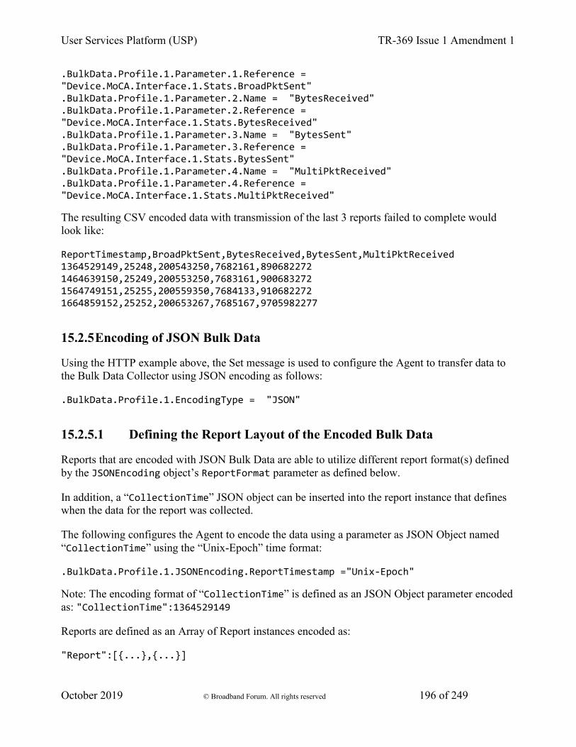
User Services Platform (USP) TR-369 Issue 1 Amendment 1
October 2019 © Broadband Forum. All rights reserved 196 of 249
.BulkData.Profile.1.Parameter.1.Reference = "Device.MoCA.Interface.1.Stats.BroadPktSent" .BulkData.Profile.1.Parameter.2.Name = "BytesReceived" .BulkData.Profile.1.Parameter.2.Reference = "Device.MoCA.Interface.1.Stats.BytesReceived" .BulkData.Profile.1.Parameter.3.Name = "BytesSent" .BulkData.Profile.1.Parameter.3.Reference = "Device.MoCA.Interface.1.Stats.BytesSent" .BulkData.Profile.1.Parameter.4.Name = "MultiPktReceived" .BulkData.Profile.1.Parameter.4.Reference = "Device.MoCA.Interface.1.Stats.MultiPktReceived"
The resulting CSV encoded data with transmission of the last 3 reports failed to complete would look like:
ReportTimestamp,BroadPktSent,BytesReceived,BytesSent,MultiPktReceived 1364529149,25248,200543250,7682161,890682272 1464639150,25249,200553250,7683161,900683272 1564749151,25255,200559350,7684133,910682272 1664859152,25252,200653267,7685167,9705982277
15.2.5 Encoding of JSON Bulk Data
Using the HTTP example above, the Set message is used to configure the Agent to transfer data to the Bulk Data Collector using JSON encoding as follows:
.BulkData.Profile.1.EncodingType = "JSON"
15.2.5.1 Defining the Report Layout of the Encoded Bulk Data
Reports that are encoded with JSON Bulk Data are able to utilize different report format(s) defined by the JSONEncoding object’s ReportFormat parameter as defined below.
In addition, a “CollectionTime” JSON object can be inserted into the report instance that defines when the data for the report was collected.
The following configures the Agent to encode the data using a parameter as JSON Object named “CollectionTime” using the “Unix-Epoch” time format:
.BulkData.Profile.1.JSONEncoding.ReportTimestamp ="Unix-Epoch"
Note: The encoding format of “CollectionTime” is defined as an JSON Object parameter encoded as: "CollectionTime":1364529149
Reports are defined as an Array of Report instances encoded as:
"Report":[{...},{...}]
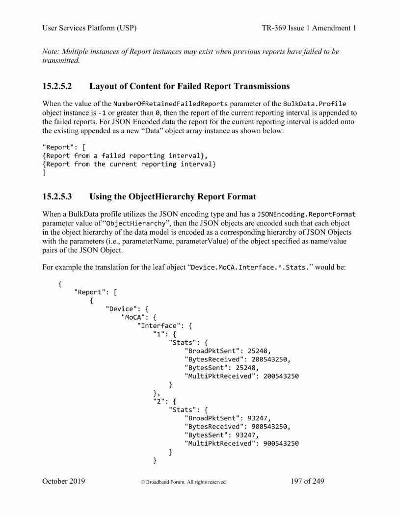
User Services Platform (USP) TR-369 Issue 1 Amendment 1
October 2019 © Broadband Forum. All rights reserved 197 of 249
Note: Multiple instances of Report instances may exist when previous reports have failed to be transmitted.
15.2.5.2 Layout of Content for Failed Report Transmissions
When the value of the NumberOfRetainedFailedReports parameter of the BulkData.Profile object instance is -1 or greater than 0, then the report of the current reporting interval is appended to the failed reports. For JSON Encoded data the report for the current reporting interval is added onto the existing appended as a new “Data” object array instance as shown below:
"Report": [ {Report from a failed reporting interval}, {Report from the current reporting interval} ]
15.2.5.3 Using the ObjectHierarchy Report Format
When a BulkData profile utilizes the JSON encoding type and has a JSONEncoding.ReportFormat parameter value of “ObjectHierarchy”, then the JSON objects are encoded such that each object in the object hierarchy of the data model is encoded as a corresponding hierarchy of JSON Objects with the parameters (i.e., parameterName, parameterValue) of the object specified as name/value pairs of the JSON Object.
For example the translation for the leaf object “Device.MoCA.Interface.*.Stats.” would be:
{ "Report": [ { "Device": { "MoCA": { "Interface": { "1": { "Stats": { "BroadPktSent": 25248, "BytesReceived": 200543250, "BytesSent": 25248, "MultiPktReceived": 200543250 } }, "2": { "Stats": { "BroadPktSent": 93247, "BytesReceived": 900543250, "BytesSent": 93247, "MultiPktReceived": 900543250 } }
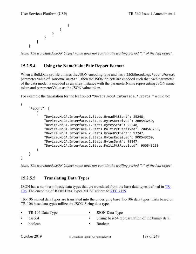
User Services Platform (USP) TR-369 Issue 1 Amendment 1
October 2019 © Broadband Forum. All rights reserved 198 of 249
} } } } ] }
Note: The translated JSON Object name does not contain the trailing period “.” of the leaf object.
15.2.5.4 Using the NameValuePair Report Format
When a BulkData profile utilizes the JSON encoding type and has a JSONEncoding.ReportFormat parameter value of “NameValuePair”, then the JSON objects are encoded such that each parameter of the data model is encoded as an array instance with the parameterName representing JSON name token and parameterValue as the JSON value token.
For example the translation for the leaf object “Device.MoCA.Interface.*.Stats.” would be:
{ "Report": [ { "Device.MoCA.Interface.1.Stats.BroadPktSent": 25248, "Device.MoCA.Interface.1.Stats.BytesReceived": 200543250, "Device.MoCA.Interface.1.Stats.BytesSent": 25248, "Device.MoCA.Interface.1.Stats.MultiPktReceived": 200543250, "Device.MoCA.Interface.2.Stats.BroadPktSent": 93247, "Device.MoCA.Interface.2.Stats.BytesReceived": 900543250, "Device.MoCA.Interface.2.Stats.BytesSent": 93247, "Device.MoCA.Interface.2.Stats.MultiPktReceived": 900543250 } ] }
Note: The translated JSON Object name does not contain the trailing period “.” of the leaf object.
15.2.5.5 Translating Data Types
JSON has a number of basic data types that are translated from the base data types defined in TR-106. The encoding of JSON Data Types MUST adhere to RFC 7159.
TR-106 named data types are translated into the underlying base TR-106 data types. Lists based on TR-106 base data types utilize the JSON String data type.
• TR-106 Data Type • JSON Data Type • base64 • String: base64 representation of the binary data. • boolean • Boolean
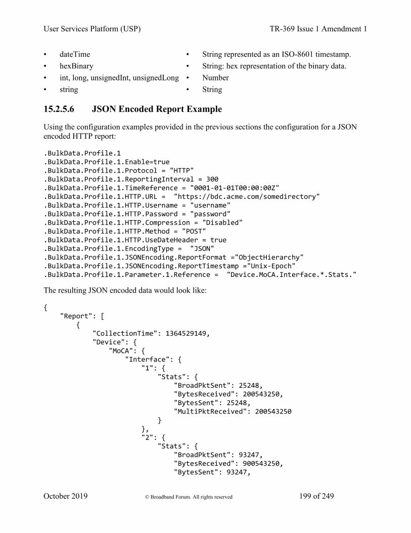
User Services Platform (USP) TR-369 Issue 1 Amendment 1
October 2019 © Broadband Forum. All rights reserved 199 of 249
• dateTime • String represented as an ISO-8601 timestamp. • hexBinary • String: hex representation of the binary data. • int, long, unsignedInt, unsignedLong • Number • string • String
15.2.5.6 JSON Encoded Report Example
Using the configuration examples provided in the previous sections the configuration for a JSON encoded HTTP report:
.BulkData.Profile.1
.BulkData.Profile.1.Enable=true
.BulkData.Profile.1.Protocol = "HTTP"
.BulkData.Profile.1.ReportingInterval = 300
.BulkData.Profile.1.TimeReference = "0001-01-01T00:00:00Z"
.BulkData.Profile.1.HTTP.URL = "https://bdc.acme.com/somedirectory"
.BulkData.Profile.1.HTTP.Username = "username"
.BulkData.Profile.1.HTTP.Password = "password"
.BulkData.Profile.1.HTTP.Compression = "Disabled"
.BulkData.Profile.1.HTTP.Method = "POST"
.BulkData.Profile.1.HTTP.UseDateHeader = true
.BulkData.Profile.1.EncodingType = "JSON"
.BulkData.Profile.1.JSONEncoding.ReportFormat ="ObjectHierarchy"
.BulkData.Profile.1.JSONEncoding.ReportTimestamp ="Unix-Epoch"
.BulkData.Profile.1.Parameter.1.Reference = "Device.MoCA.Interface.*.Stats."
The resulting JSON encoded data would look like:
{ "Report": [ { "CollectionTime": 1364529149, "Device": { "MoCA": { "Interface": { "1": { "Stats": { "BroadPktSent": 25248, "BytesReceived": 200543250, "BytesSent": 25248, "MultiPktReceived": 200543250 } }, "2": { "Stats": { "BroadPktSent": 93247, "BytesReceived": 900543250, "BytesSent": 93247,
User Services Platform (USP) TR-369 Issue 1 Amendment 1
October 2019 © Broadband Forum. All rights reserved 200 of 249
"MultiPktReceived": 900543250 } } } } } } ] }
If the value of the .BulkData.Profile.1.JSONEncoding.ReportFormat parameter was “NameValuePair”, the results of the configuration would be:
{ "Report": [ { "CollectionTime": 1364529149, "Device.MoCA.Interface.1.Stats.BroadPktSent": 25248, "Device.MoCA.Interface.1.Stats.BytesReceived": 200543250, "Device.MoCA.Interface.1.Stats.BytesSent": 25248, "Device.MoCA.Interface.1.Stats.MultiPktReceived": 200543250, "Device.MoCA.Interface.2.Stats.BroadPktSent": 93247, "Device.MoCA.Interface.2.Stats.BytesReceived": 900543250, "Device.MoCA.Interface.2.Stats.BytesSent": 93247, "Device.MoCA.Interface.2.Stats.MultiPktReceived": 900543250 } ] }
16 Appendix I - Software Module Management 1. Lifecycle Manage
2. Software Modules
1. Deployment Units
2. Execution Units
3. Execution Environment Concepts
4. Fault Model
1. DU Faults
2. EU Faults
This section discusses the Theory of Operation for Software Module Management using USP and the Software Module object defined in the Root data model.

User Services Platform (USP) TR-369 Issue 1 Amendment 1
October 2019 © Broadband Forum. All rights reserved 201 of 249
As the home networking market matures, devices in the home are becoming more sophisticated and more complex. One trend in enhanced device functionality is the move towards more standardized platforms and execution environments (such as Java, Linux, OSGi, Docker, etc.). Devices implementing these more robust platforms are often capable of downloading new applications dynamically, perhaps even from third-party software providers. These new applications might enhance the existing capabilities of the device or enable the offering of new services.
This model differs from previous device software architectures that assumed one monolithic firmware that was downloaded and applied to the device in one action.
That sophistication is a double-edged sword for developers, application providers, and service providers. On one hand, these devices are able to offer new services to customers and therefore increase the revenue per customer, help companies differentiate, and reduce churn with “sticky” applications that maintain interest. On the other hand, the increased complexity creates more opportunities for problems, especially as the users of these home-networking services cease to be early adopters and move into the mainstream. It is important that the increased revenue opportunity is not offset with growing activation and support costs.
In order to address the need of providing more compelling dynamic applications on the device while ensuring a smooth “plug and play” user experience, it is necessary for manufacturers, application providers, and service providers to make use of USP to remotely manage the life cycle of these applications, including install, activation, configuration, upgrade, and removal. Doing so ensures a positive user experience, improves service time-to-market, and reduces operational costs related with provisioning, support, and maintenance.
16.1 Lifecycle Management
There are a number of possible actions in managing the lifecycle of these dynamic applications. One might want to install a new application on the device for the user. One might want to update existing applications when new versions or patches are available. One might want to start and/or stop these applications as well. Finally, it may be necessary to uninstall applications that are no longer needed (or perhaps paid for) by the user.
The specifics of how applications run in different environments vary from platform to platform. In order to avoid lifecycle management tailored to each specific operating environment, USP-based software management defines abstract state models and abstract software module concepts as described in the following sections. These concepts are not tied to any particular platform and enable USP to manage dynamic software on a wide range of devices in a wide range of environments.
16.2 Software Modules
A Software Module is any software entity that will be installed on a device. This includes modules that can be installed/uninstalled and those that can be started and stopped. All software on the

User Services Platform (USP) TR-369 Issue 1 Amendment 1
October 2019 © Broadband Forum. All rights reserved 202 of 249
device is considered a software module, with the exception of the primary firmware, which plays a different enough role that it is considered a separate entity.
A software module exists on an Execution Environment (EE), which is a software platform that supports the dynamic loading and unloading of modules. It might also enable the dynamic sharing of resources among entities, but this differs across various execution environments. Typical examples include Linux, Docker, OSGi, .NET, Android, and Java ME. It is also likely that these environments could be “layered,” i.e., that there could be one primary environment such as Linux on which one or more OSGi frameworks are stacked. This is an implementation specific decision, however, and USP-based module management does not attempt to enable management of this layering beyond exposing which EE a given environment is layered on top of (if any). USP-based Software Module Management also does not attempt to address the management of the primary firmware image, which is expected to be managed via the device’s Firmware Image objects defined in the Root data model.
Software modules come in two types: Deployment Units (DUs) and Execution Units (EUs). A DU is an entity that can be deployed on the EE. It can consist of resources such as functional EUs, configuration files, or other resources. Fundamentally it is an entity that can be Installed, Updated, or Uninstalled. Each DU can contain zero or more EUs but the EUs contained within that DU cannot span across EEs. An EU is an entity deployed by a DU, such as services, scripts, software components, or libraries. The EU initiates processes to perform tasks or provide services. Fundamentally it is an entity that can be Started or Stopped. EUs also expose configuration for the services implemented, either via standard Software Module Management related data model objects and parameters or via EU specific objects and parameters.
It is possible that Software Modules can have dependencies on each other. For example a DU could contain an EU that another DU depends on for functioning. If all the resources on which a DU depends are present and available on an EE, it is said to be Resolved. Otherwise the EUs associated with that DU might not be able to function as designed. It is outside the scope of Software Module Management to expose these dependencies outside of indicating whether a particular DU is RESOLVED or not.
16.2.1 Deployment Units
Below is the state machine diagram1 for the lifecycle of DUs.
1 This state machine diagram refers to the successful transitions caused by the USP commands that change the DU state and does not model the error cases.

User Services Platform (USP) TR-369 Issue 1 Amendment 1
October 2019 © Broadband Forum. All rights reserved 203 of 249
Figure SMM.1 – Deployment Unit State Diagram
This state machine shows 5 individual states (3 of which are transitory) and 3 explicitly triggered state transitions.
The explicit transitions among the non-transitory states are triggered by the USP commands: InstallDU(), Update() and Uninstall() or triggered via means other than the USP commands (e.g. user-triggered or device-triggered).
The explicit transitions include:
1 - Install, which initiates the process of Installing a DU. The device might need to transfer a file from the location indicated by a URL in the method call. Once the resources are available on the device, the device begins the installation process:

User Services Platform (USP) TR-369 Issue 1 Amendment 1
October 2019 © Broadband Forum. All rights reserved 204 of 249
• In the Installing state, the DU is in the process of being Installed and will transition to that state unless prevented by a fault. Note that the Controller has the option to choose which EE to install a particular DU to, although it can also leave that choice up to the device. If the Controller does specify the EE, it is up to the Controller to specify one that is compatible with the DU it is attempting to Install (e.g., an OSGi framework for an OSGi bundle).
• In the Installed state, the DU has been successfully downloaded and installed on the relevant EE. At this point it might or might not be Resolved. If it is Resolved, the associated EUs can be started; otherwise an attempt to start the associated EUs will result in a failure. How dependencies are resolved is implementation and EE dependent.
R-SMM.0- An installed DU MUST persist across reboots. The DU persists until it is Uninstalled.
2 - Update, which initiates a process to update a previously existing DU. As with Install, the device might need to transfer a file from the location indicated by a URL in the respective command. If no URL is provided in the command, the device uses the last URL stored in the DeploymentUnit table (including any related authentication credentials) used from either Install or a previous Update. Once the resources are available on the device, the device begins the updating process:
• In the Updating state, the DU is in the process of being Updated and will transition to the Installed state. As with initial installation, the DU might or might not have dependencies resolved at this time.
• During the Updating state, the associated EUs that had been in the Active state transition to Idle during the duration of the Update. They are automatically restarted once the Update process is complete.
3 - Uninstall, which initiates the process of uninstalling the DU and removing the resources from the device. It is possible that a DU to be Uninstalled could have been providing shared dependencies to another DU; it is possible therefore that the state of other DUs and/or EUs could be affected by the DU being Uninstalled.
• In the Uninstalling state, the DU is in the process of being Uninstalled and will transition to that state unless prevented by a fault.
• In the Uninstalled state, the DU is no longer available as a resource on the device. Garbage clean up of the actual resources are EE and implementation dependent. In many cases, the resource(s) will be removed automatically at the time of un-installation. The removal of any associated EUs is part of DU clean up.
R-SMM.1 - The device MUST complete the requested operation within 24 hours of responding to the InstallDU(), Update() or Uninstall() command. If the device has not been able to complete the operation request within that 24 hour time window, it MUST consider the operation in error and send the appropriate error message to the operation in the DUStateChange! event. If a DU state change fails, the device MUST NOT attempt to retry the state change on its own initiative, but instead MUST report the failure of the command in the DUStateChange! event.
The inventory of available DUs along with their current state can be found in the SoftwareModules service element found in the Root data model, i.e., the
User Services Platform (USP) TR-369 Issue 1 Amendment 1
October 2019 © Broadband Forum. All rights reserved 205 of 249
SoftwareModules.DeploymentUnit.{i}object. This object contains a list of all the DUs currently on the device, along with pertinent information such as DU identifiers, current state, whether the DU is Resolved, information about the DU itself such as vendor and version, the list of associated EUs, and the EEs on which the particular DU is installed.
DUs have a number of identifiers, each contributed by a different actor in the ecosystem:
• A Universally Unique Identifier (UUID) either assigned by the Controller or generated by the device at the time of Installation. This identifier gives the management server a means to uniquely identify a particular DU across the population of devices on which it is installed. A DU will, therefore, have the same UUID on different devices, but there can be no more than one DU with the same UUID and version installed to an EE on a particular device. See UUID Generation below for more information.
• A Deployment Unit Identifier (DUID) assigned by the EE on which it is deployed; this identifier is specific to the particular EE, and different EEs might have different logic for the assigning of this value. A Name assigned by the author of the DU.
The creation of a particular DU instance in the data model occurs during the Installation process. It is at this time that the DUID is assigned by the EE. Upon Uninstall, the data model instance will be removed from the DU table once the resource itself has been removed from the device. Since garbage clean up is EE and implementation dependent, it is therefore possible that a particular DU might never appear in the data model in the Uninstalled state but rather disappear at the time of the state transition. It is also possible that an event, such as a reboot, could be necessary before the associated resources are removed.
16.2.1.1 UUID Generation
An important aspect of the UUID is that it might be generated by either the Controller and provided to the device as part of the Install command, or generated by the device either if the Controller does not provide a UUID in the Install command or if the DU is Installed outside USP-based management, such as at the factory or via a LAN-side mechanism (e.g. UPnP DM). Because the UUID is meant to uniquely identify a DU across a population of devices, it is important that the UUID be the same whether generated by the Controller or the device. In order to ensure this, the UUID is generated (whether by Controller or device) according to the rules defined by RFC 4122 Version 5 (Name-Based) and the Device:2 Data Model. The following are some possible scenarios:
• The DU is Installed via USP with a Controller generated UUID and is subsequently Updated/Uninstalled via USP. All post-Install management actions require the UUID to address the DU, which is retained across version changes.
• The DU is factory Installed with a device generated UUID and is subsequently Updated/Uninstalled via USP. In this case the Controller can either choose to generate this UUID if it has access to the information necessary to create it or to learn the UUID by interrogating the data model.

User Services Platform (USP) TR-369 Issue 1 Amendment 1
October 2019 © Broadband Forum. All rights reserved 206 of 249
• The DU is Installed via USP with a Controller generated UUID and is subsequently Updated/Uninstalled via a LAN-side mechanism. In this scenario it is possible that the LAN-side mechanism is unaware of the UUID and uses its own protocol-specific mechanism to identify and address the DU. The UUID, however, is still retained across version changes. If DUStateChange! events are subscribed to by the Controller for the device, the device also sends that event (containing the UUID) to the subscribed Controllers once the LAN-side triggered state change has completed.
• The DU is Installed via USP but the Controller provides no UUID in the InstallDU() command. In this case the device generates the UUID, which must be used by the Controller in any future USP-based Updates or Uninstalls. Depending on its implementation, the Controller might choose to generate the UUID at the time of the future operations, learn the value of the UUID from the DUStateChange! event for the InstallDU(), Update() or Uninstall() command, or learn it by interrogating the data model.
The DU is Installed via a LAN-side mechanism and is subsequently Updated/Uninstalled via USP. Since it is likely that the LAN-side mechanism does not provide a Version 5 Name-Based UUID in its protocol-specific Install operation, it is expected that the device generates the UUID in this case when it creates the DU instance in the data model. Depending on its implementation, the Controller might choose to generate the UUID for later operations if it has access to the information necessary to create it, learn the UUID from the DUStateChange! event, if subscribed, or learn it by interrogating the instantiated data model.
16.2.2 Execution Units
Below is the state machine diagram2 for the lifecycle of EUs.
2 This state machine diagram refers to the successful transitions caused by the SetRequestedState() command within the ExecutionUnit table and does not model the error cases.

User Services Platform (USP) TR-369 Issue 1 Amendment 1
October 2019 © Broadband Forum. All rights reserved 207 of 249
Figure SMM.2 – Execution Unit State Diagram
This state machine shows 4 states (2 of them transitory) and two explicitly triggered state transitions.
The state transitions between the non-transitory states are triggered by executing the SoftwareModules.ExecutionUnit.{i}.SetRequestedState() command. The explicit transitions are as follows:
• In order to Start an EU, the Controller sends a SetRequestedState() command with the RequestedState parameter set to Active. The EU enters the Starting state, during which it takes any necessary steps to move to the Active state, and it will transition to that state unless prevented by a fault. Note that an EU can only be successfully started if the DU with which it is associated has all dependencies Resolved. If this is not the case, then the EU’s status remains as Idle, and the ExecutionFaultCode and ExecutionFaultMessage parameters are updated appropriately.
• In order to Stop an EU, the Controller sends a SetRequestedState() command with the RequestedState parameter set to Idle. The EU enters the Stopping state, during which it takes any necessary steps to move to the Idle state, and then transitions to that state.

User Services Platform (USP) TR-369 Issue 1 Amendment 1
October 2019 © Broadband Forum. All rights reserved 208 of 249
• It is also possible that the EU could transition to the Active or Idle state without being explicitly instructed to do so by a Controller (e.g., if the EU is allowed to AutoStart, in combination with the run level mechanism, or if operation of the EU is disrupted because of a later dependency error). A Controller can be notified of these autonomous state changes by creating a Subscription.{i}. object instance for a ValueChange notification type that references the SoftwareModules.ExecutionUnit.{i}.Status parameter.
The inventory of available EUs along with their current state can be found in the SoftwareModules service element found in the Root data model; i.e., the SoftwareModules.ExecutionUnit.{i} object. This object contains a list of all the EUs currently on the device along with accompanying status and any current errors as well as resource utilization related to the EU, including memory and disk space in use.
EUs have a number of identifiers, each contributed by a different actor in the ecosystem:
• An Execution Unit Identifier (EUID) assigned by the EE on which it is deployed; this identifier is specific to the particular EE, and different EEs might have different logic for assigning this value. There can be only one EU with a particular EUID.
• A Name provided by the developer and specific to the associated DU.
• A Label assigned by the EE; this is a locally defined name for the EU.
The creation of a particular EU instance in the data model occurs during the Installation process of the associated DU. It is at this time that the EUID is assigned by the EE as well. The configuration exposed by a particular EU is available from the time the EU is created in the data model, whether or not the EU is Active. Upon Uninstall of the associated DU, it is expected that the EU would transition to the Idle State, and the data model instance would be removed from the EU table once the associated resources had been removed from the device. Garbage clean up, however, is EE and implementation dependent.
Although the majority of EUs represent resources such as scripts that can be started or stopped, there are some inert resources, such as libraries, which are represented as EUs. In this case, these EUs behave with respect to the management interface as a “regular” EU. In other words, they respond successfully to Stop and Start commands, even though they have no operational meaning and update the SoftwareModules.ExecutionUnit.{i}.Status parameter accordingly. In most cases the Status would not be expected to transition to another state on its own, except in cases where its associated DU is Updated or Uninstalled or its associated EE is Enabled or Disabled, in which cases the library EU acts as any other EU.
The EUs created by the Installation of a particular DU might provide functionality to the device that requires configuration by a Controller. This configuration could be exposed via the USP data model in five ways:
1. Service data model (if, for example, the EU provides VoIP functionality, configuration would be exposed via the Voice Service data model defined in TR-104).
User Services Platform (USP) TR-369 Issue 1 Amendment 1
October 2019 © Broadband Forum. All rights reserved 209 of 249
2. Standard objects and parameters in the device’s root data model (if, for example, the EU provides port mapping capability, the configuration would be exposed via the port mapping table defined in the Device Data Model for TR-069 Devices and USP Agents).
3. Instances of standard objects in the Root or any Service data model, (if, for example, the EU provides support for an additional Codec in a VoIP service).
4. Vendor extension objects and parameters that enhance and extend the capabilities of standard objects (if, for example, the EU provides enhanced UserInterface capabilities)
5. Standalone vendor extension objects that are directly controlled objects of the EU (for example, a new vendor specific object providing configuration for a movies on demand service).
In all cases the GetSupportedDM and GetInstances messages can be used to retrieve the associated supported data model along with the corresponding object instances.
All data model services, objects, and parameters related to a particular EU come into existence at the time of Installation or Update of the related DU, The related data model disappears from the device’s data model tree at the time of Uninstall and clean up of the related DU resources. It is possible that the device could encounter errors during the process of discovering and creating EUs; if this happens, it is not expected that the device would roll back any data model it has created up until this point but would rather set the ExecutionFaultCode of the EU to “Unstartable.” In this case, it is not expected that any faults (with the exception of System Resources Exceeded) would have been generated in response to the Install or Update operation. See below for more information on EU faults.
The configuration of EUs could be backed up and restored using vendor configuration files. The EU object in the data model contains a parameter, which is a path reference to an instance in the vendor config file table in the Root data model. This path reference indicates the vendor config file associated with the configuration of the particular EU from which the associated object instance could be backed up or restored using respective commands for that object instance.
It is also possible that applications could have dedicated log files. The EU object also contains a parameter, which is a path reference to an instance in the log file table in the root data model. This path reference indicates the log file associated with a particular EU from which the referenced object instance could be retrieved using the Upload command for that object instance.
16.3 Execution Environment Concepts
As discussed above, an EE is a software platform that supports the dynamic loading and unloading of modules. A given device can have multiple EEs of various types and these EEs can be layered on top of each other. The following diagram gives a possible implementation of multiple EEs.
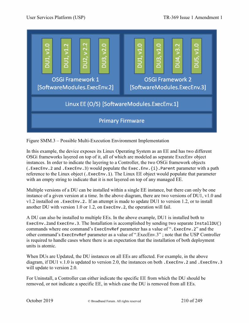
User Services Platform (USP) TR-369 Issue 1 Amendment 1
October 2019 © Broadband Forum. All rights reserved 210 of 249
Figure SMM.3 – Possible Multi-Execution Environment Implementation
In this example, the device exposes its Linux Operating System as an EE and has two different OSGi frameworks layered on top of it, all of which are modeled as separate ExecEnv object instances. In order to indicate the layering to a Controller, the two OSGi framework objects (.ExecEnv.2 and .ExecEnv.3) would populate the Exec.Env.{i}.Parent parameter with a path reference to the Linux object (.ExecEnv.1). The Linux EE object would populate that parameter with an empty string to indicate that it is not layered on top of any managed EE.
Multiple versions of a DU can be installed within a single EE instance, but there can only be one instance of a given version at a time. In the above diagram, there are two versions of DU1, v1.0 and v1.2 installed on .ExecEnv.2. If an attempt is made to update DU1 to version 1.2, or to install another DU with version 1.0 or 1.2, on ExecEnv.2, the operation will fail.
A DU can also be installed to multiple EEs. In the above example, DU1 is installed both to ExecEnv.2and ExecEnv.3. The Installation is accomplished by sending two separate InstallDU() commands where one command’s ExecEnvRef parameter has a value of “.ExecEnv.2” and the other command’s ExecEnvRef parameter as a value of “.ExecEnv.3” ; note that the USP Controller is required to handle cases where there is an expectation that the installation of both deployment units is atomic.
When DUs are Updated, the DU instances on all EEs are affected. For example, in the above diagram, if DU1 v.1.0 is updated to version 2.0, the instances on both .ExecEnv.2 and .ExecEnv.3 will update to version 2.0.
For Uninstall, a Controller can either indicate the specific EE from which the DU should be removed, or not indicate a specific EE, in which case the DU is removed from all EEs.

User Services Platform (USP) TR-369 Issue 1 Amendment 1
October 2019 © Broadband Forum. All rights reserved 211 of 249
An EE can be enabled and disabled by a Controller. Reboot of an EE is accomplished by first disabling and then later enabling the EE. When an EE instance is disabled by a Controller, the EE itself shuts down. Additionally, any EUs associated with the EE automatically transition to Stopped and the ExecutionFaultCode parameter value is Unstartable. The state of the associated DUs remains the same. If a USP command that changes the DU state is attempted on any of the DUs associated with a disabled EE, the operation fails and an “Invalid value” error is returned in the DUStateChange! event for the affected DU instance. It should be noted if the Operating System of the device is exposed as an EE, disabling it could result in the device being put into a non-operational and non-manageable state. It should also be noted that disabling the EE on which the USP agent resides can result in the device becoming unmanageable via USP.
Note that the above is merely an example; whether a device supports multiple frameworks of the same type and whether it exposes its Operating System as an Execution Environment for the purposes of management is implementation specific.
16.4 Fault Model
Faults can occur at a number of steps in the software module process. The following sections discuss Deployment Unit faults and Execution Unit faults.
16.4.1 DU Faults
There are two basic types of DU faults: Operation failures and USP message errors that are the result of the invoking the InstallDU(),Update(),UninstallDU(), Reset(), SetRunLevel() and SetRequestedState() commands.
16.4.1.1 Install Faults
Most Install faults will be recognized before resources or instances are created on the device. When there is an Operation failure at Install, there are no resources installed on the device and no DU (or EU) instances are created in the data model. Similarly, if there are any command failures, besides System Resources Exceeded, there are no resources installed on the device and no DU (or EU) instances created in the data model.
There are a number of command failures defined for Installation. The first category is those faults associated with the file server or attempt to transfer the DU resource and are the same as those defined for the existing InstallDU() and Update() commands. These include:
• Userinfo element being specified in the URL
• The URL being unavailable (either because the host cannot be reached or because the resource is unavailable)
• Authentication failures due to incorrectly supplied credentials
User Services Platform (USP) TR-369 Issue 1 Amendment 1
October 2019 © Broadband Forum. All rights reserved 212 of 249
• The URL transport method specified not being supported by the device or server
• The file transfer being interrupted (because of a device reboot or loss of connectivity, for example)
The second category of faults relate to issues with the DU and the Execution Environment. These are specific to Software Module Management and include:
• The EE reference specified by a Controller in the InstallDU() command does not exist in the data model. Note that the Controller can simply omit the EE reference in the request and allow the deice to choose the destination.
• The EE being disabled. This fault can occur when the InstallDU() command explicitly specifies a disabled EE. If there is no EE specified in the request, this fault could occur because the only possible destination EE for the DU (the only OSGi framework instance in the case of an OSGi bundle, for example) is disabled. The device is expected to make every attempt not to use a disabled EE in this scenario, however.
• Any mismatch existing between the DU and the EE (attempting to install a Linux package on an OSGi framework instance, for example). This fault can occur when the request explicitly specifies a mismatching EE. If there is no EE specified in the request, this fault could occur when there is no EE at all on the device that can support the DU.
• A DU of the same version already existing on the EE.
Finally there are a number of faults related to the DU resource itself. These include:
• The UUID in the request not matching the format specified in RFC 4122 Version 5 (Name-based).
• A corrupted DU resource, or the DU not being installable for other reasons, such as not being signed by any trusted entity
• The installation of the DU requiring more system resources, such as disk space, memory, etc., than the device has available. Note that this error is not to be used to indicate that more operations have been requested than the device can support, which is indicated by the Resourced Exceeded error (described above).
16.4.1.2 Update Faults
When there is a fault on an Update of a DU of any kind, the DU remains at the version it was before the attempted DU state change, and it also remains in the Installed state (i.e., it is not Uninstalled). If for any reason the a Controller wishes to remove a DU after an unsuccessful Update, it must do so manually using an Uninstall() command. When there is a USP message error for the Update, there are no new resources installed on the device and no DU (or EU) instances are changed in the data model. Similarly, if there are any Operation failures, besides System Resources Exceeded, there are no new resources installed on the device and no DU (or EU) instances are changed in the
User Services Platform (USP) TR-369 Issue 1 Amendment 1
October 2019 © Broadband Forum. All rights reserved 213 of 249
data model. The state of any associated EUs or any dependent EUs in the event of an Update failure is EE and implementation dependent.
There are a number of Operation failures defined for Update of a DU. The first category is those faults associated with the file server or attempt to transfer the DU resource and are the same as those defined for the existing Update() command. These include:
• Userinfo element being specified in the URL
• The URL being unavailable (either because the host cannot be reached or because the resource is unavailable)
• Authentication failures due to incorrectly supplied credentials
• The URL transport method specified not being supported by the device or server
• The file transfer being interrupted (because of a device reboot or loss of connectivity, for example)
The second category of faults relate to issues with the DU and the Execution Environment. These are specific to Software Module Management and include:
• The EE on which the targeted DU resides being disabled. This fault can occur when the request explicitly specifies the UUID of a DU on a disabled EE or when the request explicitly specifies a URL last used by a DU on a disabled EE. If neither the URL nor UUID was specified in the request, this fault can occur when at least one DU resides on a disabled EE.
• Any mismatch existing between the DU and the EE. This fault occurs when the content of the updated DU does not match the EE on which it resides (for example, an attempt is made to Update a Linux package with a DU that is an OSGi bundle).
• Updating the DU would cause it to have the same version as a DU already installed on the EE.
• The version of the DU not being specified in the request when there are multiple versions installed on the EE.
Finally there are a number of faults related to the DU resource itself. These include:
• The UUID in the request not matching the format specified in RFC 4122 Version 5 (Name-Based).
• A corrupted DU resource, or the DU not being installable for other reasons, such as not being signed by any trusted entity
• The DU cannot be found in the data model. This fault can occur when the request explicitly specifies the UUID (or combination of UUID and version) of a DU that is unknown. It can also occur when the request does not specify a UUID but explicitly specifies a URL that has never been used to previously Install or Update a DU.
• Attempting to downgrade the DU version.
User Services Platform (USP) TR-369 Issue 1 Amendment 1
October 2019 © Broadband Forum. All rights reserved 214 of 249
• Attempting to Update a DU not in the Installed state.
• Updating the DU requiring more system resources, such as disk space, memory, etc., than the device has available. Note that this error is not to be used to indicate that more operations have been requested than the device can support, which is indicated by the Resourced Exceeded USP error (described above).
16.4.1.3 Uninstall Faults
When there is a fault due to the Uninstall of a DU fault of any kind, the DU does not transition to the Uninstalled state and no resources are removed from the device. No changes are made to the EU-related portions of the data model (including the EU objects themselves and the related objects and parameters that came into existence because of this DU).
There are Operation failures defined for Uninstall of a DU. They are as follows:
• The EE on which the targeted DU resides is disabled. Note that if the Uninstall operation targets DUs across multiple EEs, this fault will occur if at least one of the EEs on which the DU resides is disabled.
• The DU cannot be found in the data model. If the EE is specified in the request, this error occurs when there is no UUID (or UUID and version) matching the one requested for the specified EE. If there is no EE specified in the request, this error occurs when there is no UUID matching the one in the requested on any EE in the data model, or, if the version is also specified in the request, then this error occurs when there is no DU with this combination of UUID and version on any EE in the data model.
• The UUID in the request not matching the format specified in RFC 4122 Version 5 (Name- Based).
• The DU caused an EE to come into existence on which at least 1 DU is Installed.
16.4.2 EU Faults
EU state transitions are triggered by the SetRequestedState() command. One type of EU fault is a USP error message sent in response to USP operate message for the SetRequestedState() command. The USP Error message defined are therefore simply a subset of the errors defined for the generic USP Operate message( e.g., Request Denied, Internal Error).
Note that there is one case specific to Software Module Management: if a Controller tries to Start an EU on a disabled EE using the SetRequestedState() command, the device returns a “7012 Invalid Value” error response to the command request.
There are also Software Module Management specific faults indicated in the ExecutionFaultCode and ExecutionFaultMessage parameters in the data model. In addition to providing software module specific fault information, this parameter is especially important in a number of scenarios:

User Services Platform (USP) TR-369 Issue 1 Amendment 1
October 2019 © Broadband Forum. All rights reserved 215 of 249
• Errors that occur at a later date than the original USP message, such as a Dependency Failure that occurs several days after successful Start of an EU because a DU providing dependencies is later Uninstalled.
• State transition errors that are triggered by the Autostart/Run level mechanism.
• “Autonomous” state transitions triggered outside the purview of USP, such as by a LAN-side protocol.
The faults in the ExecutionFaultCode parameter are defined as follows:
• FailureOnStart – the EU failed to start despite being requested to do so by the Controller.
• FailureOnAutoStart – the EU failed to start when enabled to do so automatically.
• FailureOnStop – the EU failed to stop despite being requested to do so by the Controller.
• FailureWhileActive – an EU that had previously successfully been started either via an explicit transition or automatically later fails.
• DependencyFailure – this is a more specific fault scenario in which the EU is unable to start or stops at a later date because of unresolved dependencies
• Unstartable – some error with the EU resource, its configuration, or the state of the associated DU or EE, such as the EE being disabled, prevents it from being started.
When the EU is not currently in fault, this parameter returns the value NoFault. The ExecutionFaultMessage parameter provides additional, implementation specific information about the fault in question. The ExecutionFaultCode and ExecutionFaultMessage parameters are triggered parameters. In other words, it is not expected that an Controller could read this parameter before issuing a USP message and see that there was a Dependency Failure that it would attempt to resolve first. If a Controller wants a notification when these parameters change, the Controller can subscribe to the ValueChange notification type with the parameters for the referenced EU.
17 Appendix I - Firmware Management of Devices with USP Agents 1. Getting the firmware image onto the device
2. Using multiple firmware images
1. Switching firmware images
2. Performing a delayed firmware upgrade
3. Recovering from a failed upgrade
Many manufacturers build and deploy devices that are able to support multiple firmware images (i.e. multiple firmware images can be installed on an Agent at the same time). There are at least a couple of advantages to this strategy:
User Services Platform (USP) TR-369 Issue 1 Amendment 1
October 2019 © Broadband Forum. All rights reserved 216 of 249
1. Having multiple firmware images installed improves the robustness and stability of the device because, in all likelihood, one of the installed images will be stable and bootable. Should a device not be able to boot a newly installed firmware image, it could have the ability to attempt to boot from a different firmware image, thus allowing the device to come back online.
2. Support for multiple firmware images offers the ability for the service provider to have a new firmware downloaded (but not activated) to the device at any point during the day, then perhaps requiring only a Set message and an Operate message to invoke the Reboot command at some later time (perhaps during a short maintenance window or when the device is idle) to cause the device to switch over to the new firmware. Along with reducing the impact on the subscriber, the ability to spread the download portion a firmware upgrade over a longer period of time (eg, the entire day or over several days) can help minimize the impact of the upgrade on the provider’s network.
This Appendix discusses how to utilize the firmware image table on a device to support firmware upgrades whether the device supports multiple instances or just a single instance.
17.1 Getting the firmware image onto the device
A Controller can download a firmware image to an Agent by invoking the Download() command (via the Operate message) found within an instance of the Device.FirmwareImage.{i}. data model table. The Download() command will cause the referenced file to be downloaded into the firmware image instance being operated on, and it will cause that file to be validated by the Agent (the validation process would include any normal system validate of a firmware image as well as the check sum validation provided in the Download() command).
If an Agent only supports a single firmware image instance then a Controller would invoke the Download() command on that active firmware image instance using the AutoActivate argument to immediately activate the new firmware after it has been downloaded. Neither the Device.DeviceInfo.BootFirmwareImage parameter nor the Device.DeviceInfo.FirmwareImage.{i}.Activate() command would typically be implemented by a device that only supports a single firmware image instance.
If an Agent supports more than a single firmware image instance then a Controller would typically invoke the Download() command on a non-active firmware image instance in an effort of preserving the current firmware image in case of an error while upgrading the firmware. A firmware image instance is considered active if it is the currently running firmware image.
17.2 Using multiple firmware images
This section discusses the added functionality available when a device supports two or more instances in the Device.FirmwareImage.{i}. data model table.
User Services Platform (USP) TR-369 Issue 1 Amendment 1
October 2019 © Broadband Forum. All rights reserved 217 of 249
17.2.1 Switching firmware images
Once a device has multiple firmware images downloaded, validated, and available, a Controller can use the data model to query what images are on the device, which image is active, and configure which image to activate.
A Controller can activate a new firmware image by following one of two different procedures: (A) the Controller can modify the Device.DeviceInfo.BootFirmwareImage parameter to point to the Device.DeviceInfo.FirmwareImage.{i}. object instance that contains the desired firmware image and then reboot the device by invoking an Operate message with a Reboot() command or (B) the Controller can invoke an Operate message with an Activate() command against the desired FirmwareImage instance.
When attempting to get a device to switch to a different firmware image, it is recommended that the Controller either subscribe to a ValueChange notification on the DeviceInfo.SoftwareVersion parameter or subscribe to the Boot! Event notification. If the Software Version value has not changed or the Boot! Event’s FirmwareUpdated argument is false, it could be an indication that the device had problems booting the target firmware image.
17.2.2 Performing a delayed firmware upgrade
One of the benefits to having support for multiple firmware images on a device is that it provides an opportunity to push a firmware image to a device and then have the device switch to that image at a later time. This functionally allows a service provider to push a firmware image to a set of devices at any point during the day and then use a maintenance window to switch all of the target devices to the target firmware.
This ability is of value because normally the download of the firmware and the switch to the new image would both have to take place during the maintenance window. Bandwidth limitations may have an impact on the number of devices that can be performing the download at the same time. If this is the case, the number of devices that can be upgrading at the same time may be lower than desired, requiring multiple maintenance windows to complete the upgrade. However, support for multiple firmware images allows for the service provider to push firmware images over a longer period of time and then use a smaller maintenance window to tell the device to switch firmware images. This can result is shorter system-wide firmware upgrades.
17.2.3 Recovering from a failed upgrade
Another benefit of having multiple firmware images on a device is that if a device cannot boot into a target firmware image because of some problem with the image, the device could then try to boot one of the other firmware images.
When there are two images, the device would simply try booting the alternate image (which, ideally, holds the previous version of the firmware). If there are more than two images, the device could try booting from any of the other available images. Ideally, the device would keep track of
User Services Platform (USP) TR-369 Issue 1 Amendment 1
October 2019 © Broadband Forum. All rights reserved 218 of 249
and try to boot from the previously known working firmware (assuming that firmware is still installed on the device).
Should the device boot a firmware image other than that specified via the Device.DeviceInfo.BootFirmwareImage parameter, it is important that the device not change the value of the Device.DeviceInfo.BootFirmwareImage parameter to point to the currently-running firmware image object. If the device was to change this parameter value, it could make troubleshooting problems with a firmware image switch more difficult.
It was recommended above that the Controller keep track of the value of Device.DeviceInfo.SoftwareVersion parameter or the FirmwareActivation enumerated value in the Boot! Event’s Cause argument. If the version changes unexpectedly or a FirmwareActivation cause is detected, it could be an indication that the device had problems booting a particular firmware image.
18 Appendix III - Device Proxy This appendix describes a Theory of Operations for the Device.ProxiedDevice. object defined in the Device:2 Data Model.
The Device.ProxiedDevice table is defined as:
“Each entry in the table is a ProxiedDevice object that is a mount point. Each ProxiedDevice represents distinct hardware Devices. ProxiedDevice objects are virtual and abstracted representation of functionality that exists on hardware other than that which the Agent is running.”
An implementation of the Device.ProxiedDevice. object may be used in an IoT Gateway that proxies devices that are connected to it via technologies other tha USP such as Z-Wave, ZigBee, Wi-Fi, etc. By designating a table of ProxiedDevice objects, each defined as a mount point, this allows a data model with objects that are mountable to be used to represent the capabilities of each of the ProxiedDevice table instances.
For example, if Device.WiFi. and Device.TemperatureSensor. objects modeled by the Agent, the Device.ProxiedDevice.1.WiFi.Radio.1. models a distinctly separate hardware device and has no relationship with Device.WiFi.Radio.1.. The ProxiedDevice objects may each represent entirely different types of devices each with a different set of objects. The ProxiedDevice.1.TemperatureSensor.1. object has no physical relationship to ProxiedDevice.2.TemperatureSensor.1. as they represent temperature sensors that exist on separate hardware. The mount point allows Device.ProxiedDevice.1.WiFiRadio. and Device.ProxiedDevice.1.TemperatureSensor. to represent the full set of capabilities for the device being proxied. This provides a Controller a distinct path to each ProxiedDevice object.
19 Appendix IV - Proxying 1. Proxying Building Block Functions
User Services Platform (USP) TR-369 Issue 1 Amendment 1
October 2019 © Broadband Forum. All rights reserved 219 of 249
2. Discovery Proxy
3. Connectivity Proxy
4. Message Transfer Protocol (MTP) Proxy
1. MTP Header Translation Algorithms
2. CoAP / STOMP MTP Proxy Example Message Flow
5. USP to Non-USP Proxy
This appendix describes a variety of proxies that can be created and deployed in order to enhance the USP experience.
The types of proxies described are:
• Discovery Proxy: proxies discovery and advertisement; does not proxy USP messages
• Connectivity Proxy: proxies USP messages at the IP layer; does not care about MTP or USP message headers or content; may do message caching for sleeping devices
• MTP Proxy: proxies USP messages at the MTP layer and below; does not care about USP Message headers or content; may do message caching for sleeping devices [Note: The MTP Proxy may choose to look at the USP Record to get information related to USP Endpoints, especially when proxying WebSocket MTP.]
• USP to Non-USP Proxy: Proxies between USP and a non-USP management or control protocol
19.1 Proxying Building Block Functions
These proxies are comprised of one or more of the building block functions described in the Table PRX.1.
Table PRX.1: Proxy Building Block Functions
• Function • Description • L3/4
Translation Function
• Translates up to and including the IP and transport layer (e.g., UDP, TCP) protocol headers, while leaving all higher layer protocol headers and payloads untouched.
• MTP Translation Function
• Translates up to and including the Message Transfer Protocol (MTP) header, while leaving the USP Record untouched. Requires knowledge of how to bind USP to two or more MTPs.
• USP to non-USP Translation Function
• Translates all headers and the USP Record and USP Message into data model and headers of another management protocol. Requires proxy to have an Agent.
User Services Platform (USP) TR-369 Issue 1 Amendment 1
October 2019 © Broadband Forum. All rights reserved 220 of 249
• Caching Function
• Can hold on to USP Messages intended for Endpoints that are intermittently connected, until a time when that Endpoint is connected. The USP Message is not altered, so no Endpoint is required to be aware of the existence of this function.
• Non-USP Advertisement Function
• Responds to discovery queries using protocols other than USP (e.g., DNS-SD, DNS, DHCP) on behalf of Endpoints. May include a DNS Server. See Discovery section for formatting of various non-USP discovery protocols in the context of USP.
• Non-USP Discovery Function
• Discovers Endpoints through discovery queries using protocols other than USP. See Discovery section for formatting of various non-USP discovery protocols in the context of USP.
• Agent USP Advertisement Function
• Maintains a USP data model table of discovered Agents. Requires an Agent.
19.2 Discovery Proxy
A Discovery Proxy simply repeats the exact information that it discovers from Endpoints. This is particularly useful in a multi-segment LAN, where mDNS messages do not cross segment boundaries. The DNS-SD Discovery Proxy functionality is recommended as a component of a Discovery Proxy. When used inside a LAN, this would need the Non-USP Discovery Function and the Non-USP Advertisement Function described in Table PRX.1.
An Agent USP Advertisement Function would be needed to support Endpoints in different networks (e.g., discovery of Agents on the LAN by a Controller on the WAN).
USP Messages between proxied Endpoints go directly between the Endpoints and do not go across the Discovery Proxy. The Discovery Proxy has no role in USP outside discovery.
19.3 Connectivity Proxy
This describes proxying of discovery and IP connectivity of Endpoints that need IP address or port translation to communicate, and/or do not maintain continual IP connectivity. The Connectivity Proxy may cache USP Messages on behalf of Endpoints that do not maintain continual connectivity. The USP Message is not processed by the proxy function, but it does go through the proxy for address translation or so it can be cached, if necessary. Therefore, the connectivity information provided by the Connectivity Proxy directs IP packets (that contain the USP Records) be sent to the proxy and not to the destination IP address of the Endpoint being proxied.
Both Endpoints must be using the same MTP. This Proxy translates the IP address (and possibly the TCP or UDP port) from the Connectivity Proxy to the proxied Endpoint, but does not touch (or need to understand) the MTP headers or USP Message.
It is also possible to combine the caching functionality with the MTP Proxy, by adding the Caching Function to the MTP Proxy (see Section 3).
User Services Platform (USP) TR-369 Issue 1 Amendment 1
October 2019 © Broadband Forum. All rights reserved 221 of 249
In order to serve as a Connectivity Proxy, the following functions (from Table PRX.1) are needed: 1. L3/4 Translation Function 1. Depending on whether the proxy is on the same network as the proxied Endpoints: 1. Non-USP Discovery Function and/or otherwise determined/configured knowledge of Agent(s) 1. Non-USP Advertisement Function and/or Agent USP Advertisement Function
The Connectivity Proxy can also include the Caching Function to support Endpoints with intermittent connectivity.
19.4 Message Transfer Protocol (MTP) Proxy
This describes proxying between two USP Endpoints that do not support a common MTP. The USP Record is untouched by the proxy function. MTP and IP headers are changed by the proxy.
In order to serve as a MTP Proxy, the following functions (from Table PRX.1) are needed:
1. MTP Translation Function
2. Depending on whether it is on the same network as the proxied Agents and/or the Controller that wants to communicate with those Agents:
1. Non-USP Discovery Function and/or otherwise determined/configured knowledge of Agent(s)
2. Non-USP Advertisement Function and/or Agent USP Advertisement Function
The MTP Proxy can also include the Caching Function to support Endpoints with intermittent connectivity.
19.4.1 MTP Header Translation Algorithms
In order to implement a meaningful translation algorithm, the MTP Proxy will need to: 1. Maintain mapping of discovered or configured Endpoint information to information the MTP Proxy generates or is configured with. This allows it to advertise that Endpoint on a different MTP and to translate the MTP when it receives a message destined for that Endpoint. 1. Maintain a mapping of received “reply to” and other connection information to connection and “reply to” information included by the MTP Proxy in the sent message. This allows it to translate the MTP when it receives a response message destined for that Endpoint. 1. Identify the target Endpoint for a received message.
The following information will need to be stored in a maintained mapping for an Endpoint:
1. URL -or- the IP Address (es) (IPv4 and/or IPv6) and UDP or TCP ports -or- the socket for an established connection (note that the information and configured data needed to establish this connection is out-of-scope of this specification)
2. MTP-specific destination information (including destination resource)
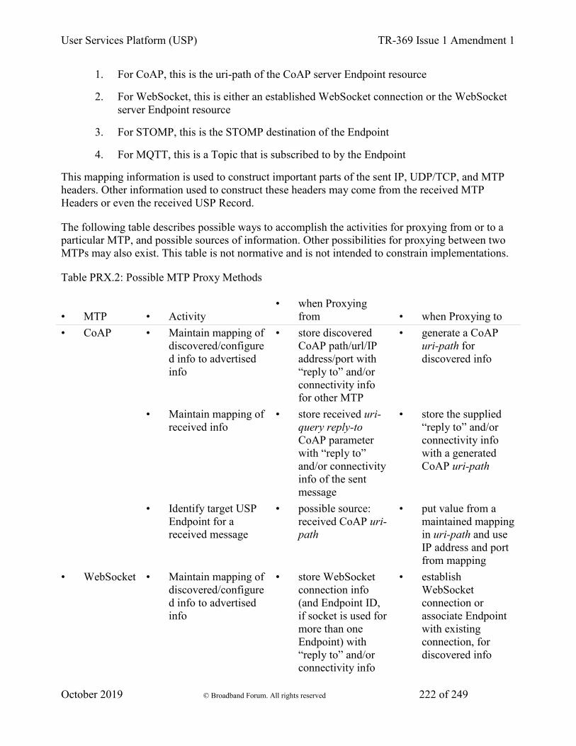
User Services Platform (USP) TR-369 Issue 1 Amendment 1
October 2019 © Broadband Forum. All rights reserved 222 of 249
1. For CoAP, this is the uri-path of the CoAP server Endpoint resource
2. For WebSocket, this is either an established WebSocket connection or the WebSocket server Endpoint resource
3. For STOMP, this is the STOMP destination of the Endpoint
4. For MQTT, this is a Topic that is subscribed to by the Endpoint
This mapping information is used to construct important parts of the sent IP, UDP/TCP, and MTP headers. Other information used to construct these headers may come from the received MTP Headers or even the received USP Record.
The following table describes possible ways to accomplish the activities for proxying from or to a particular MTP, and possible sources of information. Other possibilities for proxying between two MTPs may also exist. This table is not normative and is not intended to constrain implementations.
Table PRX.2: Possible MTP Proxy Methods
• MTP • Activity • when Proxying
from • when Proxying to • CoAP • Maintain mapping of
discovered/configured info to advertised info
• store discovered CoAP path/url/IP address/port with “reply to” and/or connectivity info for other MTP
• generate a CoAP uri-path for discovered info
• Maintain mapping of received info
• store received uri-query reply-to CoAP parameter with “reply to” and/or connectivity info of the sent message
• store the supplied “reply to” and/or connectivity info with a generated CoAP uri-path
• Identify target USP Endpoint for a received message
• possible source: received CoAP uri-path
• put value from a maintained mapping in uri-path and use IP address and port from mapping
• WebSocket • Maintain mapping of discovered/configured info to advertised info
• store WebSocket connection info (and Endpoint ID, if socket is used for more than one Endpoint) with “reply to” and/or connectivity info
• establish WebSocket connection or associate Endpoint with existing connection, for discovered info

User Services Platform (USP) TR-369 Issue 1 Amendment 1
October 2019 © Broadband Forum. All rights reserved 223 of 249
for other MTP • Maintain mapping of
received info • store WebSocket
connection info (and Endpoint ID, if socket is used for more than one Endpoint) with “reply to” and/or connectivity info for other MTP
• store the supplied “reply to” and/or connectivity info with a WebSocket connection (and Endpoint ID, if socket is used for more than one Endpoint)
• Identify target USP Endpoint for a received message
• possible source: WebSocket connection established per proxied Endpoint possible source: to_id in USP Record
• send over WebSocket connection associated with the proxied Endpoint
• STOMP • Maintain mapping of discovered/configured info to advertised info
• store subscribed-to STOMP destination with “reply to” and/or connectivity info for other MTP
• subscribe to STOMP destination for discovered info
• Maintain mapping of received info
• store reply-to-dest STOMP header (and associated STOMP connection) with “reply to” or socket info of the sent message
• store the supplied “reply to” and/or connectivity info with subscribed-to STOMP destination and connection
• Identify target USP Endpoint for a received message
• possible source: received STOMP destination possible source: to_id in USP Record
• put value from maintained mapping in STOMP destination header and use STOMP connection from that mapping
• MQTT • Maintain mapping of discovered/configured info to advertised info
• store subscribed-to Topic (Filter) with “reply to” and/or connectivity info for other MTP
• subscribe to MQTT Topic (Filter) for discovered info (if Topic Filter, know which specific Topic to use for “reply to” info)
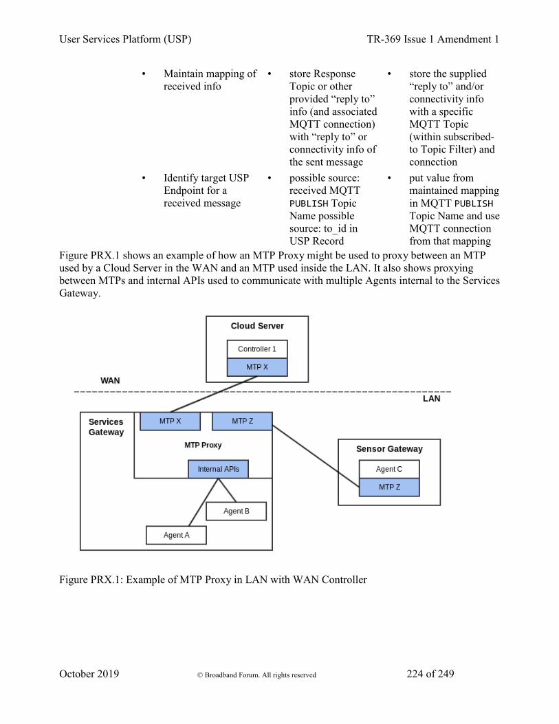
User Services Platform (USP) TR-369 Issue 1 Amendment 1
October 2019 © Broadband Forum. All rights reserved 224 of 249
• Maintain mapping of received info
• store Response Topic or other provided “reply to” info (and associated MQTT connection) with “reply to” or connectivity info of the sent message
• store the supplied “reply to” and/or connectivity info with a specific MQTT Topic (within subscribed-to Topic Filter) and connection
• Identify target USP Endpoint for a received message
• possible source: received MQTT PUBLISH Topic Name possible source: to_id in USP Record
• put value from maintained mapping in MQTT PUBLISH Topic Name and use MQTT connection from that mapping
Figure PRX.1 shows an example of how an MTP Proxy might be used to proxy between an MTP used by a Cloud Server in the WAN and an MTP used inside the LAN. It also shows proxying between MTPs and internal APIs used to communicate with multiple Agents internal to the Services Gateway.
Figure PRX.1: Example of MTP Proxy in LAN with WAN Controller
User Services Platform (USP) TR-369 Issue 1 Amendment 1
October 2019 © Broadband Forum. All rights reserved 225 of 249
19.4.2 CoAP / STOMP MTP Proxy Example Message Flow
The following example is provided as a detailed look at a sample CoAP (LAN) / STOMP (WAN) MTP Proxy to describe one possible way to do discovery, connectivity and security. This example makes several assumptions as to the nature of the STOMP connection between the MTP Proxy and the STOMP server, which is completely undefined. It also makes assumptions about implemented, enabled and configured Agent capabilities.
Assumptions include: * a STOMP connection per proxied device * the STOMP server supplies a subscribe-dest header in CONNECTED frames (this is optional for a STOMP server) * there exists some means for the Controller to discover the proxied Agent connection to the STOMP server * the CoAP Agent does mDNS advertisement (optional but recommended behavior) * the CoAP Agent and Proxy support and have enabled DTLS * the CoAP Agent has been configured with the Proxy’s certificate for use as a Trusted Broker. * the proxy uses the subscribe-dest value (supplied by the STOMP server) as the value for the reply-to-dest header.
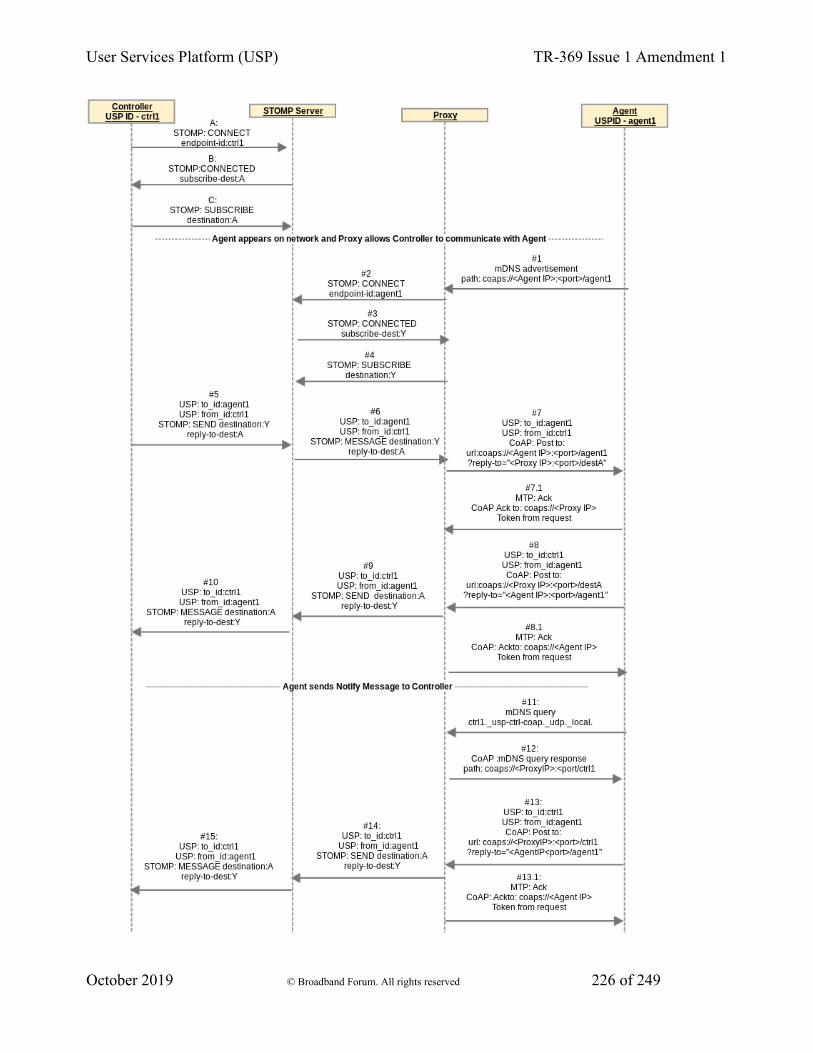
User Services Platform (USP) TR-369 Issue 1 Amendment 1
October 2019 © Broadband Forum. All rights reserved 226 of 249
User Services Platform (USP) TR-369 Issue 1 Amendment 1
October 2019 © Broadband Forum. All rights reserved 227 of 249
Figure PRX.2: CoAP-STOMP MTP Proxy Example Flow
Controller connects to the STOMP server
A / B / C At any point prior to #5 the USP Controller Endpoint ctrl1 connects to STOMP and subscribes to destination A
• OUT OF SCOPE how the USP Endpoint ctrl1 destination A is discovered by Proxy
• OUT OF SCOPE how the proxied USP Endpoint agent1 STOMP destination Y is discovered by USP Endpoint ctrl1
Agent appears on network and Proxy allows Controller to communicate with Agent
#1 The USP Endpoint agent1 appears on the network. Proxy receives advertisement and gets the USP Endpoint identifier “agent1” of the Agent (retrieved from mDNS advertisement see R-DIS.8).
#2 Proxy sends a CONNECT frame to the STOMP server with endpoint-id header of “agent1”.
#3 Proxy receives a subscribe-dest header in the CONNECTED frame identifying the STOMP destination it needs to subscribe to on behalf of agent1.
#4 The Proxy sends a SUBSCRIBE frame to the STOMP server with destination:Y and stores a mapping of USP Endpoint agent1 with coaps://<Agent IP>:<port>/agent1 to this STOMP connection with destination Y.
#5 / #6 USP Endpoint ctrl1 initiates USP message to agent. Proxy creates a STOMP reply-to-dest:A (on this STOMP connection) to coaps://<Proxy IP>:<port>/destA mapping.
#7/ #7.1 Proxy takes USP Record from the STOMP frame and sends it in a CoAP payload with CoAP URI coming from the step #4 mapping of STOMP destination Y to coap://<Agent IP>:<port>/agent1. To secure the communication, the proxy and Agent establish a DTLS session (exchange certificates) and the Agent determines whether the proxy is a Trusted Broker.
#8 / #8.1 USP Endpoint agent1 sends a USP Record in reply to ctrl1 using CoAP, to coaps://<Proxy IP>:<port>/destA.
#9 / #10 Proxy takes USP Record from the CoAP payload and sends it in a STOMP SEND frame using the mapping (created in steps #5 / #6) of coaps://<Proxy IP>:<port>/destA to STOMP destination A (and associated STOMP connection) created in steps #5 / #6 .
Agent sends Notify Message to Controller
These steps include the following additional assumptions: * Controller has configured Agent with a notification subscription. * Controller configured Agent with CoAP MTP information for itself. * Proxy replies to mDNS queries for Controller with “ctrl1” Instance. Controller was able to assume or otherwise determine that Proxy would do this and that its proxied CoAP connection would be discoverable by querying for ctrl1._usp-ctrl-coap._udp._local. * Proxy can use the previous reply-to-dest header value to reach this Controller
User Services Platform (USP) TR-369 Issue 1 Amendment 1
October 2019 © Broadband Forum. All rights reserved 228 of 249
#11 The Agent sends mDNS query for ctrl1._usp-ctrl-coap._udp._local.
#12 The Proxy response to the Agent includes TXT record with path of coaps://<Proxy IP>:<port>/ctrl1. This provides a URL for the Agent to use to send a Notify Message to the Controller.
#13 / #13.1 The Agent sends a Notify Message to Controller at coaps://<Proxy IP>:<port>/ctrl1.
#14 / #15 Proxy takes the USP Record from the CoAP payload and sends it in a STOMP SEND frame using the mapping (stored in #5 / #6 ) of coaps://<Proxy IP>:<port>/destA to STOMP destination:A (and associated STOMP connection).
19.5 USP to Non-USP Proxy
This describes proxying between a Controller and some other management protocol with its own data model schema (e.g., UPnP DM, ZigBee, NETCONF, RESTCONF). In this case the proxy is expected to maintain a USP representation of the non-USP data. This requires the proxy to expose itself as a full Agent to the Controller. See the Device Proxy appendix for the Theory of Operations for the Device.ProxiedDevice. object defined in the Device:2 Data Model.
In order to serve as a USP to non-USP Proxy, the USP to non-USP Translation Function (from Table PRX.1) is needed.
20 Appendix V - IoT Data Model Theory of Operation
20.1 Introduction
Since there are thousands of different Internet of Things (IoT) devices, the data model needs a flexible modular way to support them using generic building block templates. To achieve this, an IoT device is represented in the data model by sensor and control capabilities:
• Sensor capabilities, which allow reading a state, e.g. a temperature value, a battery level, a light color, etc.
• Control capabilities, which allow changing a value, e.g. set a temperature, switch a light etc.
The Device:2 data model defines capability objects that reflect capabilities found on many different devices (example: BinaryControl). By using these objects, a large ecosystem of devices can be described using a small set of capabilities (see table below).
20.2 IoT data model overview
The figure shows the overall structure of the IoT data model:
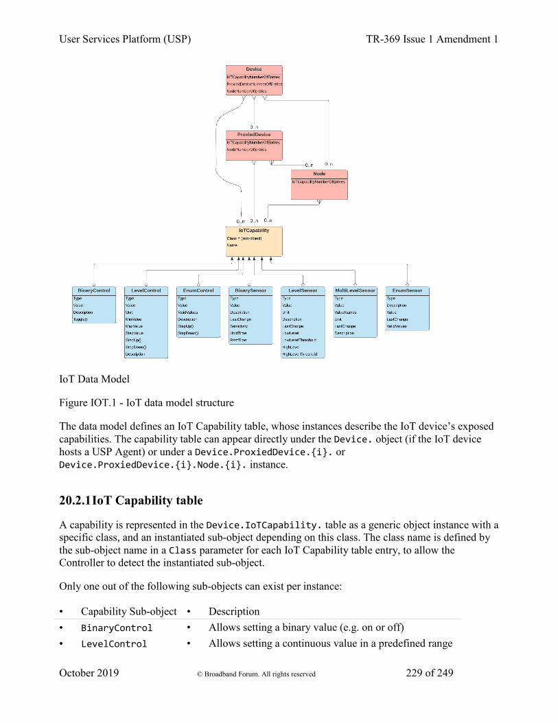
User Services Platform (USP) TR-369 Issue 1 Amendment 1
October 2019 © Broadband Forum. All rights reserved 229 of 249
IoT Data Model
Figure IOT.1 - IoT data model structure
The data model defines an IoT Capability table, whose instances describe the IoT device’s exposed capabilities. The capability table can appear directly under the Device. object (if the IoT device hosts a USP Agent) or under a Device.ProxiedDevice.{i}. or Device.ProxiedDevice.{i}.Node.{i}. instance.
20.2.1 IoT Capability table
A capability is represented in the Device.IoTCapability. table as a generic object instance with a specific class, and an instantiated sub-object depending on this class. The class name is defined by the sub-object name in a Class parameter for each IoT Capability table entry, to allow the Controller to detect the instantiated sub-object.
Only one out of the following sub-objects can exist per instance:
• Capability Sub-object • Description • BinaryControl • Allows setting a binary value (e.g. on or off) • LevelControl • Allows setting a continuous value in a predefined range

User Services Platform (USP) TR-369 Issue 1 Amendment 1
October 2019 © Broadband Forum. All rights reserved 230 of 249
• EnumControl • Allows setting a value from a predefined set of values • BinarySensor • Provides a binary reading value (true/false) • LevelSensor • Provides a continuous reading value • MultiLevelSensor • Provides multiple reading values, which belong together Each IoT capability sub-object has a Type parameter to identify the functionality the capability is representing. See the Type definition section for details.
20.2.2 Node object table
The Device.Node.{i}. and Device.ProxiedDevice.{i}.Node.{i}. objects are mount points that provide the ability to support complex devices - that is, a group of capabilities. Each node is a container for a group of device capabilities that have a direct relationship with each other (sub-device) and a hierarchal relationship with the top-level. A node may have the same capabilities as the top-level, but applicable only for the node, with no impact to the top-level. Capabilities for the top-level node may have an effect on the lower level nodes, such as power.
20.3 Architecture mappings
20.3.1 Individual IoT devices
Stand-alone IoT devices, which are capable of supporting their own USP Agent, provide their own data models, which expose the IoT sensor and control capabilities of the device:
Figure IOT.2 - IoT individual device models
Each device registers as an individual entity to the USP Controller. With the help of Node objects, the capabilities can be additionally structured (not shown in the picture).

User Services Platform (USP) TR-369 Issue 1 Amendment 1
October 2019 © Broadband Forum. All rights reserved 231 of 249
20.3.2 Proxied IoT devices
IoT devices connected over a proxy protocol (e.g. ZigBee) with an IoT control device hosting the USP Agent are modeled as proxied devices (i.e., using the Device.ProxiedDevice. table) in the data model of the control device’s USP Agent:
Figure IOT.3 - IoT proxied device model
Each IoT device is represented as a Device.ProxiedDevice.{i}. instance in the data model of the control device, which exposes its IoT capabilities in the corresponding objects. The capabilities can be additionally structured with the help of Node object (not shown in the picture).
20.4 IoT data model object details
20.4.1 Common capability parameters
These parameters have the same behavior for all capability sub-objects, where defined.
20.4.1.1 Type definition
Applies to: All capability sub-objects
All capability objects contain a mandatory Type enumeration value.
The Type value is a predefined enumeration value with the goal of giving a unified description of the capability object. If the Type value requires further detail, the Description parameter may provided a further definition.
Note: The Type enumeration in the data model can also be extended with vendor-specific values like all TR-181 parameters, using the rules defined in TR-106.
User Services Platform (USP) TR-369 Issue 1 Amendment 1
October 2019 © Broadband Forum. All rights reserved 232 of 249
20.4.1.2 Unit definition
Applies to: LevelControl, LevelSensor, MultilevelSensor
To define the used unit a similar concept as for the type definition is used. The definition consists of the Unit enumeration value.
The Unit value is a predefined enumeration value with the goal of giving a unified representation of the used unit.
Note: The Unit enumeration in the data model can also be extended with vendor-specific values like all TR-181 parameters, using the rules defined in TR-106.
Note - Imperial units are intentionally not modeled in favor of the metric system to increase the inter-working. If the Controller needs imperial units, it can easily convert the metric units into imperial ones by using the well-defined conversion routines.
20.4.2 Control Objects
Control objects represent IoT capabilities that involve the manipulation of device or application states. They include Binary Controls, Level Controls, and Enumerated Controls.
20.4.2.1 BinaryControl
The binary controller defines the simplest type of controller, which allows to switch between two values like true/false, on/off, full/empty, etc. Its value is modeled as a Boolean, which can be either true or false.
The minimum definition of a “BinaryControl” consists of:
IoTCapability.i.Class = "BinaryControl" IoTCapability.i.BinaryControl.Type = ... IoTCapability.i.BinaryControl.Value = ...
The value can be changed either directly by a USP Set operation, or via The Toggle() command, which corresponds to the behavior of a switch, changing the value to the other state.
20.4.2.2 LevelControl
The level controller capability allows a continuous change of a value within a predefined range. Its capabilities are defined by these three mandatory parameters:
• Unit - The unit used for the value
• MinValue - The minimum value the value can be set
User Services Platform (USP) TR-369 Issue 1 Amendment 1
October 2019 © Broadband Forum. All rights reserved 233 of 249
• MaxValue - The maximum value the value can be set
Implementations have to provide the minimum and maximum values to allow the controller to detect what values can be applied.
The minimum definition of a “LevelControl” consists of:
IoTCapability.i.Class = "LevelControl" IoTCapability.i.LevelControl.Type = ... IoTCapability.i.LevelControl.Unit = ... IoTCapability.i.LevelControl.MinValue = ... IoTCapability.i.LevelControl.MaxValue = ... IoTCapability.i.LevelControl.Value = ...
The value can be changed either directly by a USP Set operation, or via the step commands.
If the StepUp() command and/or the StepDown() command are implemented, the StepValue parameter has to be implemented, which indicates the amount of change triggered by a step command. If resulting value of a step command would exceed the defined range, the operation does not result in a failure - instead, the result is set to the range limit value.
For example, if a temperature range is defined from 5.5 degC to 25 degC with a step value of 1 degC, a step down from 6 degC would result in 5.5 degC and not in 5 degC.
Additionally, if the lowest possible value is already set, a StepDown() will not change the current value, since the defined minimum range would be exceeded. The same also applies to the maximum value and StepUp() command.
20.4.2.3 EnumControl
The enumeration controller capability allows setting one of a set of predefined values. Examples are mode selections, with more than two modes. If only two values exist, the binary controller object is preferred.
The minimum definition of an “EnumControl” consists of:
IoTCapability.i.Class = "EnumControl" IoTCapability.i.EnumControl.Type = ... IoTCapability.i.EnumControl.ValidValues = <list of possible values> IoTCapability.i.EnumControl.Value = <current value>
The value can be changed either directly by a USP Set operation, or via the step commands.
The step commands will cycle through the value range, meaning that if the last valid value is reached, the next StepUp() command will select the first value of the valid values and vice versa for the StepDown() command. The valid values are stored in the parameter ValidValues as a comma-separated list; that order of the list will be followed by the step commands.
User Services Platform (USP) TR-369 Issue 1 Amendment 1
October 2019 © Broadband Forum. All rights reserved 234 of 249
It is possible to implement only one of the step commands, if only one direction is needed.
20.4.3 Sensor Objects
Sensor objects represent IoT capabilities that involve reading or reporting on a device or application state. They include Binary Sensors, Level Sensors, and Enumerated Sensors, along with support for thresholds and triggering events.
20.4.3.1 Binary Sensor
The binary sensor object instance supports different kinds of binary sensor operations:
• Simple binary state, e.g. a door or window state
• Threshold trigger, e.g. trigger a Carbon Dioxide Alarm if a certain threshold is exceeded.
• Repeated trigger with grace period, e.g. movement detector.
20.4.3.1.1 Simple binary state sensor
To model a simple sensor, which changes between two distinct states (e.g. a window or door open/close sensor), only the Value parameter is needed.
The minimum definition of a BinarySensor consists of:
IoTCapability.i.Class = "BinarySensor" IoTCapability.i.BinarySensor.Type = ... IoTCapability.i.BinarySensor.Value = {true/false}
The values of true and false represent the two possible Value states. Each time the state changes the value toggles.
For example, a motion sensor would be modeled as:
IoTCapability.i.Class = "BinarySensor" IoTCapability.i.BinarySensor.Type = "MotionDetected" IoTCapability.i.BinarySensor.Value = true
Note that binary sensor types are meaningful for binary state behavior, e.g., “WindowOpen” rather than “Window”.
20.4.3.1.2 Threshold trigger sensor
To model a sensor, which additionally triggers on a certain threshold, add the Sensitivity parameter to the definition:
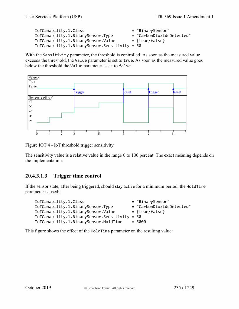
User Services Platform (USP) TR-369 Issue 1 Amendment 1
October 2019 © Broadband Forum. All rights reserved 235 of 249
IoTCapability.1.Class = "BinarySensor" IoTCapability.1.BinarySensor.Type = "CarbonDioxideDetected" IoTCapability.1.BinarySensor.Value = {true/false} IoTCapability.1.BinarySensor.Sensitivity = 50
With the Sensitivity parameter, the threshold is controlled. As soon as the measured value exceeds the threshold, the Value parameter is set to true. As soon as the measured value goes below the threshold the Value parameter is set to false.
Figure IOT.4 - IoT threshold trigger sensitivity
The sensitivity value is a relative value in the range 0 to 100 percent. The exact meaning depends on the implementation.
20.4.3.1.3 Trigger time control
If the sensor state, after being triggered, should stay active for a minimum period, the HoldTime parameter is used:
IoTCapability.1.Class = "BinarySensor" IoTCapability.1.BinarySensor.Type = "CarbonDioxideDetected" IoTCapability.1.BinarySensor.Value = {true/false} IoTCapability.1.BinarySensor.Sensitivity = 50 IoTCapability.1.BinarySensor.HoldTime = 5000
This figure shows the effect of the HoldTime parameter on the resulting value:
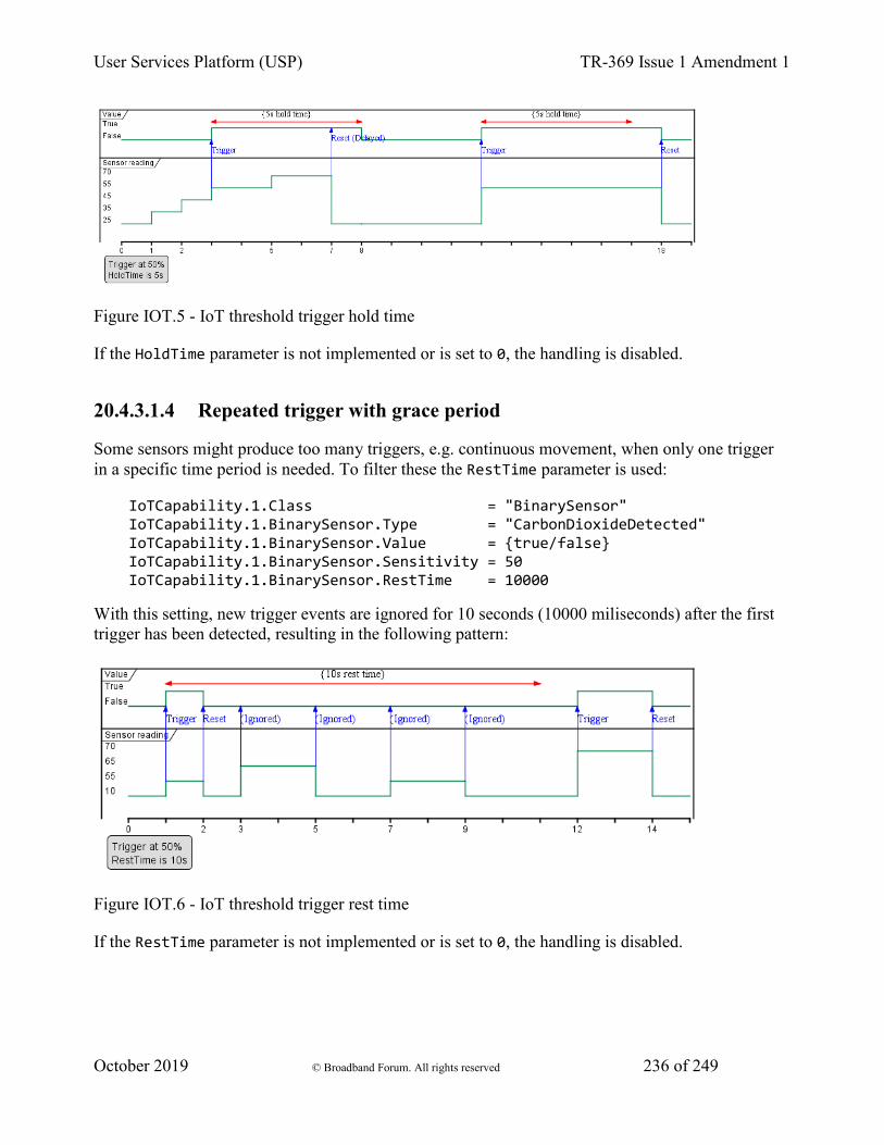
User Services Platform (USP) TR-369 Issue 1 Amendment 1
October 2019 © Broadband Forum. All rights reserved 236 of 249
Figure IOT.5 - IoT threshold trigger hold time
If the HoldTime parameter is not implemented or is set to 0, the handling is disabled.
20.4.3.1.4 Repeated trigger with grace period
Some sensors might produce too many triggers, e.g. continuous movement, when only one trigger in a specific time period is needed. To filter these the RestTime parameter is used:
IoTCapability.1.Class = "BinarySensor" IoTCapability.1.BinarySensor.Type = "CarbonDioxideDetected" IoTCapability.1.BinarySensor.Value = {true/false} IoTCapability.1.BinarySensor.Sensitivity = 50 IoTCapability.1.BinarySensor.RestTime = 10000
With this setting, new trigger events are ignored for 10 seconds (10000 miliseconds) after the first trigger has been detected, resulting in the following pattern:
Figure IOT.6 - IoT threshold trigger rest time
If the RestTime parameter is not implemented or is set to 0, the handling is disabled.
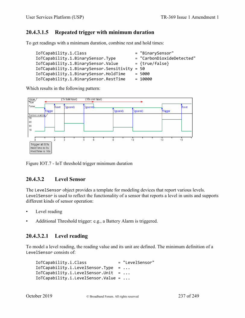
User Services Platform (USP) TR-369 Issue 1 Amendment 1
October 2019 © Broadband Forum. All rights reserved 237 of 249
20.4.3.1.5 Repeated trigger with minimum duration
To get readings with a minimum duration, combine rest and hold times:
IoTCapability.1.Class = "BinarySensor" IoTCapability.1.BinarySensor.Type = "CarbonDioxideDetected" IoTCapability.1.BinarySensor.Value = {true/false} IoTCapability.1.BinarySensor.Sensitivity = 50 IoTCapability.1.BinarySensor.HoldTime = 5000 IoTCapability.1.BinarySensor.RestTime = 10000
Which results in the following pattern:
Figure IOT.7 - IoT threshold trigger minimum duration
20.4.3.2 Level Sensor
The LevelSensor object provides a template for modeling devices that report various levels. LevelSensor is used to reflect the functionality of a sensor that reports a level in units and supports different kinds of sensor operation:
• Level reading
• Additional Threshold trigger: e.g., a Battery Alarm is triggered.
20.4.3.2.1 Level reading
To model a level reading, the reading value and its unit are defined. The minimum definition of a LevelSensor consists of:
IoTCapability.i.Class = "LevelSensor" IoTCapability.i.LevelSensor.Type = ... IoTCapability.i.LevelSensor.Unit = ... IoTCapability.i.LevelSensor.Value = ...

User Services Platform (USP) TR-369 Issue 1 Amendment 1
October 2019 © Broadband Forum. All rights reserved 238 of 249
For example, to show the remaining load of a battery in percent, this capability would have the following values:
IoTCapability.1.Class = "LevelSensor" IoTCapability.1.LevelSensor.Type = "Battery" IoTCapability.1.LevelSensor.Unit = "%" IoTCapability.1.LevelSensor.Value = 63"
With this definition, the remaining load is expressed in percent, here 63 percent. Since the unit value is a decimal type it is also possible to specify fractions for the value:
IoTCapability.1.Class = "LevelSensor" IoTCapability.1.LevelSensor.Type = "Battery" IoTCapability.1.LevelSensor.Unit = "%" IoTCapability.1.LevelSensor.Value = 63.26
This expresses a total remaining load of 63.26 percent.
20.4.3.2.2 Threshold trigger
In cases where not only the actual value is of interest, but also important to know if a predefined threshold is reached or undershot, the LevelSensor object can be extended with threshold parameters. Once the LowLevel or HighLevel parameter is true, it will remain true until the device is reset or the condition no longer exists. This will depend on the particular device.
• Parameter • Type • R/W • Description • LowLevel • boolean • R • True means that the low level
threshold is reached or undershot. • LowLevelThreshold • decimal • R/W • The defined low level value. • HighLevel • boolean • R • True means that the high level
threshold is reached or exceeded. • HighLevelThreshold • decimal • R/W • The defined high level value. Table 17 – IoT LevelSensor threshold parameters
When modeling a battery with a LevelSensor object, an additional low level warning (Boolean) may be supported along with a Low Level threshold that provides a setting for the warning. The resulting object looks like this:
IoTCapability.1.Class = "LevelSensor" IoTCapability.1.LevelSensor.Type = "Battery" IoTCapability.1.LevelSensor.Unit = "%" IoTCapability.1.LevelSensor.LowLevelThreshold = 20 IoTCapability.1.LevelSensor.Value = 19 IoTCapability.1.LevelSensor.LowLevel = true
Note - For more complex scenarios, like having a grace period, the binary sensor object can be used instead of the LowLevel or HighLevel Threshold parameters.
User Services Platform (USP) TR-369 Issue 1 Amendment 1
October 2019 © Broadband Forum. All rights reserved 239 of 249
20.4.3.2.3 Multi Level Sensor
A MultiLevelSensor instance models sensors, which provide a set of related values with the same unit.
The minimum definition of a “MultiLevelSensor” consists of:
IoTCapability.i.Class = "MultiLevelSensor" IoTCapability.i.MultiLevelSensor.Type = ... IoTCapability.i.MultiLevelSensor.Unit = ... IoTCapability.i.MultiLevelSensor.Values = ... IoTCapability.1.MultiLevelSensor.ValueNames = ...
An example is a location reading consisting of the two values longitude and latitude in decimal degree notation, which have to be read together:
IoTCapability.1.Class = "MultiLevelSensor" IoTCapability.1.MultiLevelSensor.Type = "Location" IoTCapability.1.MultiLevelSensor.Unit = "deg" IoTCapability.1.MultiLevelSensor.Values = "48.1372056,11.57555" IoTCapability.1.MultiLevelSensor.ValueNames = "Latitude,Longitude"
This example uses the parameter ValueNames to provide information about the individual value meanings.
20.4.3.3 Enum Sensor
An EnumSensor instance provides a reading value from a predefined set of values. This allows modeling of sensors, which can output discreet values from a predefined set.
The minimum definition of an “EnumSensor” consists of:
IoTCapability.i.Class = "EnumSensor" IoTCapability.i.EnumSensor.Type = ... IoTCapability.i.EnumSensor.Unit = ... IoTCapability.i.EnumSensor.ValidValues = ... IoTCapability.i.EnumSensor.Value = ...
The ValidValues parameter determines the set of values, which will be delivered by the sensor.
For example, a traffic light could be modeled as:
IoTCapability.1.Class = "EnumSensor" IoTCapability.1.EnumSensor.Type = "X_<oui>_TrafficLight" IoTCapability.1.EnumSensor.ValidValues = "Red, Yellow, Green" IoTCapability.1.EnumSensor.Value = "Green"
20.5 Examples

User Services Platform (USP) TR-369 Issue 1 Amendment 1
October 2019 © Broadband Forum. All rights reserved 240 of 249
This chapter gives several examples how to model IoT Devices.
20.5.1 Example: A/C Thermostat
This example shows an A/C Thermostat connected over Z-Wave as a proxied device of an IoT Gateway:
Structure elements:
• IoTCapability.1 (EnumControl) : Operation Mode
• IoTCapability.2 (LevelControl) : Cool Temperature in range from 14 to 25 degC
• IoTCapability.3 (LevelControl) : Heat Temperature in range from 14 to 25 degC
• IoTCapability.4 (LevelControl) : Energy Saving Cool Temperature in range from 14 to 25 degC
• IoTCapability.5 (LevelControl) : Energy Saving Heat Temperature in range from 14 to 25 degC
• IoTCapability.6 (LevelSensor) : Current Temperature
• IoTCapability.7 (EnumControl) : Fan Mode Control
• IoTCapability.8 (EnumSensor) : Current Fan Operating State
Instantiated data model:
ProxiedDevice.1.Type = "Thermostat" ProxiedDevice.1.Online = true ProxiedDevice.1.ProxyProtocol = "Z-Wave" ProxiedDevice.1.IoTCapabilityNumberOfEntries = 9 ProxiedDevice.1.IoTCapability.1.Class = "EnumControl" ProxiedDevice.1.IoTCapability.1.EnumControl.Type = "ThermostatMode" ProxiedDevice.1.IoTCapability.1.EnumControl.Value = "Cool" ProxiedDevice.1.IoTCapability.1.EnumControl.ValidValues = "Heat, Cool, Energy_heat, Energy_cool, Off, Auto" ProxiedDevice.1.IoTCapability.2.Class = "LevelControl" ProxiedDevice.1.IoTCapability.2.LevelControl.Type = "Temperature" ProxiedDevice.1.IoTCapability.2.LevelControl.Description = "TargetCoolTemperature" ProxiedDevice.1.IoTCapability.2.LevelControl.Value = 17 ProxiedDevice.1.IoTCapability.2.LevelControl.Unit = "degC" ProxiedDevice.1.IoTCapability.2.LevelControl.MinValue = 14
User Services Platform (USP) TR-369 Issue 1 Amendment 1
October 2019 © Broadband Forum. All rights reserved 241 of 249
ProxiedDevice.1.IoTCapability.2.LevelControl.MaxValue = 25 ProxiedDevice.1.IoTCapability.3.Class = "LevelControl" ProxiedDevice.1.IoTCapability.3.LevelControl.Type = "Temperature" ProxiedDevice.1.IoTCapability.3.LevelControl.Description = "TargetHeatTemperature" ProxiedDevice.1.IoTCapability.3.LevelControl.Value = 21 ProxiedDevice.1.IoTCapability.3.LevelControl.Unit = "degC" ProxiedDevice.1.IoTCapability.3.LevelControl.MinValue = 14 ProxiedDevice.1.IoTCapability.3.LevelControl.MaxValue = 25 ProxiedDevice.1.IoTCapability.4.Class = "LevelControl" ProxiedDevice.1.IoTCapability.4.LevelControl.Type = "Temperature" ProxiedDevice.1.IoTCapability.4.LevelControl.Description = "TargetEnergyCoolTemp" ProxiedDevice.1.IoTCapability.4.LevelControl.Value = 19 ProxiedDevice.1.IoTCapability.4.LevelControl.Unit = "degC" ProxiedDevice.1.IoTCapability.4.LevelControl.MinValue = 14 ProxiedDevice.1.IoTCapability.4.LevelControl.MaxValue = 25 ProxiedDevice.1.IoTCapability.5.Class = "LevelControl" ProxiedDevice.1.IoTCapability.5.LevelControl.Type = "Temperature" ProxiedDevice.1.IoTCapability.5.LevelControl.Description = "TargetEnergyHeatTemp" ProxiedDevice.1.IoTCapability.5.LevelControl.Value = 19 ProxiedDevice.1.IoTCapability.5.LevelControl.Unit = "degC" ProxiedDevice.1.IoTCapability.5.LevelControl.MinValue = 14 ProxiedDevice.1.IoTCapability.5.LevelControl.MaxValue = 25 ProxiedDevice.1.IoTCapability.6.Class = "LevelSensor" ProxiedDevice.1.IoTCapability.6.LevelSensor.Type = "Temperature" ProxiedDevice.1.IoTCapability.6.LevelSensor.Value = 19.5 ProxiedDevice.1.IoTCapability.6.LevelSensor.Unit = "degC" ProxiedDevice.1.IoTCapability.7.Class = "EnumControl" ProxiedDevice.1.IoTCapability.7.EnumControl.Type = "FanMode" ProxiedDevice.1.IoTCapability.7.EnumControl.Value = "Low" ProxiedDevice.1.IoTCapability.7.EnumControl.ValidValues = "Auto_low, Low, Circulation, Off" ProxiedDevice.1.IoTCapability.8.Class = "EnumSensor" ProxiedDevice.1.IoTCapability.8.EnumSensor.Type = "OperatingState" ProxiedDevice.1.IoTCapability.8.EnumSensor.Value = "Cooling" ProxiedDevice.1.IoTCapability.8.EnumSensor.ValidValues = "Heating, Cooling, FanOnly, PendingHeat, PendingCool, VentEconomizer, AuxHeating, 2ndStageHeating, 2ndStageCooling, 2ndStageAuxHeat, 3rdStageAuxHeat"
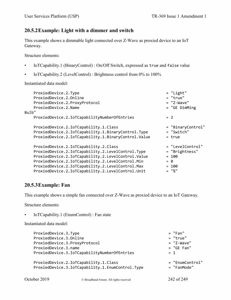
User Services Platform (USP) TR-369 Issue 1 Amendment 1
October 2019 © Broadband Forum. All rights reserved 242 of 249
20.5.2 Example: Light with a dimmer and switch
This example shows a dimmable light connected over Z-Wave as proxied device to an IoT Gateway.
Structure elements:
• IoTCapability.1 (BinaryControl) : On/Off Switch, expressed as true and false value
• IoTCapability.2 (LevelControl) : Brightness control from 0% to 100%
Instantiated data model:
ProxiedDevice.2.Type = "Light" ProxiedDevice.2.Online = "true" ProxiedDevice.2.ProxyProtocol = "Z-Wave" ProxiedDevice.2.Name = "GE DimMing Bulb" ProxiedDevice.2.IoTCapabilityNumberOfEntries = 2 ProxiedDevice.2.IoTCapability.1.Class = "BinaryControl" ProxiedDevice.2.IoTCapability.1.BinaryControl.Type = "Switch" ProxiedDevice.2.IoTCapability.1.BinaryControl.Value = true ProxiedDevice.2.IoTCapability.2.Class = "LevelControl" ProxiedDevice.2.IoTCapability.2.LevelControl.Type = "Brightness" ProxiedDevice.2.IoTCapability.2.LevelControl.Value = 100 ProxiedDevice.2.IoTCapability.2.LevelControl.Min = 0 ProxiedDevice.2.IoTCapability.2.LevelControl.Max = 100 ProxiedDevice.2.IoTCapability.2.LevelControl.Unit = "%"
20.5.3 Example: Fan
This example shows a simple fan connected over Z-Wave as proxied device to an IoT Gateway.
Structure elements:
• IoTCapability.1 (EnumControl) : Fan state
Instantiated data model:
ProxiedDevice.3.Type = "Fan" ProxiedDevice.3.Online = "true" ProxiedDevice.3.ProxyProtocol = "Z-Wave" ProxiedDevice.3.name = "GE Fan" ProxiedDevice.3.IoTCapabilityNumberOfEntries = 1 ProxiedDevice.2.IoTCapability.1.Class = "EnumControl" ProxiedDevice.3.IoTCapability.1.EnumControl.Type = "FanMode"
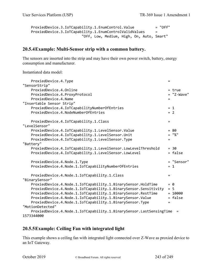
User Services Platform (USP) TR-369 Issue 1 Amendment 1
October 2019 © Broadband Forum. All rights reserved 243 of 249
ProxiedDevice.3.IoTCapability.1.EnumControl.Value = "Off" ProxiedDevice.3.IoTCapability.1.EnumControlValidValues = "Off, Low, Medium, High, On, Auto, Smart"
20.5.4 Example: Multi-Sensor strip with a common battery.
The sensors are inserted into the strip and may have their own power switch, battery, energy consumption and manufacturer.
Instantiated data model:
ProxiedDevice.4.Type = "SensorStrip" ProxiedDevice.4.Online = true ProxiedDevice.4.ProxyProtocol = "Z-Wave" ProxiedDevice.4.Name = "Insertable Sensor Strip" ProxiedDevice.4.IoTCapabilityNumberOfEntries = 1 ProxiedDevice.4.NodeNumberOfEntries = 2 ProxiedDevice.4.IoTCapability.1.Class = "LevelSensor" ProxiedDevice.4.IoTCapability.1.LevelSensor.Value = 80 ProxiedDevice.4.IoTCapability.1.LevelSensor.Unit = "%" ProxiedDevice.4.IoTCapability.1.LevelSensor.Type = "Battery" ProxiedDevice.4.IoTCapability.1.LevelSensor.LowLevelThreshold = 30 ProxiedDevice.4.IoTCapability.1.LevelSensor.LowLevel = false ProxiedDevice.4.Node.1.Type = "Sensor" ProxiedDevice.4.Node.1.IoTCapabilityNumberOfEntries = 1 ProxiedDevice.4.Node.1.IoTCapability.1.Class = "BinarySensor" ProxiedDevice.4.Node.1.IoTCapability.1.BinarySensor.HoldTime = 0 ProxiedDevice.4.Node.1.IoTCapability.1.BinarySensor.Sensitivity = 5 ProxiedDevice.4.Node.1.IoTCapability.1.BinarySensor.RestTime = 10000 ProxiedDevice.4.Node.1.IoTCapability.1.BinarySensor.Value = false ProxiedDevice.4.Node.1.IoTCapability.1.BinarySensor.Type = "MotionDetected" ProxiedDevice.4.Node.1.IoTCapability.1.BinarySensor.LastSensingTime = 1573344000
20.5.5 Example: Ceiling Fan with integrated light
This example shows a ceiling fan with integrated light connected over Z-Wave as proxied device to an IoT Gateway.
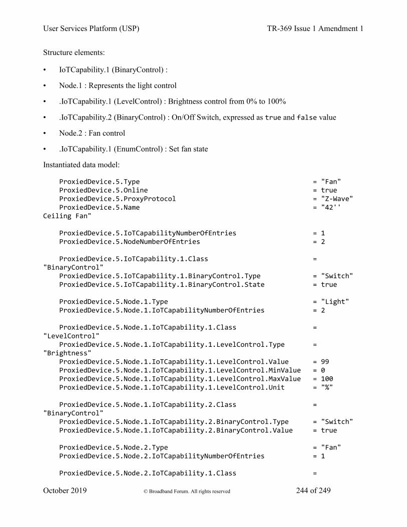
User Services Platform (USP) TR-369 Issue 1 Amendment 1
October 2019 © Broadband Forum. All rights reserved 244 of 249
Structure elements:
• IoTCapability.1 (BinaryControl) :
• Node.1 : Represents the light control
• .IoTCapability.1 (LevelControl) : Brightness control from 0% to 100%
• .IoTCapability.2 (BinaryControl) : On/Off Switch, expressed as true and false value
• Node.2 : Fan control
• .IoTCapability.1 (EnumControl) : Set fan state
Instantiated data model:
ProxiedDevice.5.Type = "Fan" ProxiedDevice.5.Online = true ProxiedDevice.5.ProxyProtocol = "Z-Wave" ProxiedDevice.5.Name = "42'' Ceiling Fan" ProxiedDevice.5.IoTCapabilityNumberOfEntries = 1 ProxiedDevice.5.NodeNumberOfEntries = 2 ProxiedDevice.5.IoTCapability.1.Class = "BinaryControl" ProxiedDevice.5.IoTCapability.1.BinaryControl.Type = "Switch" ProxiedDevice.5.IoTCapability.1.BinaryControl.State = true ProxiedDevice.5.Node.1.Type = "Light" ProxiedDevice.5.Node.1.IoTCapabilityNumberOfEntries = 2 ProxiedDevice.5.Node.1.IoTCapability.1.Class = "LevelControl" ProxiedDevice.5.Node.1.IoTCapability.1.LevelControl.Type = "Brightness" ProxiedDevice.5.Node.1.IoTCapability.1.LevelControl.Value = 99 ProxiedDevice.5.Node.1.IoTCapability.1.LevelControl.MinValue = 0 ProxiedDevice.5.Node.1.IoTCapability.1.LevelControl.MaxValue = 100 ProxiedDevice.5.Node.1.IoTCapability.1.LevelControl.Unit = "%" ProxiedDevice.5.Node.1.IoTCapability.2.Class = "BinaryControl" ProxiedDevice.5.Node.1.IoTCapability.2.BinaryControl.Type = "Switch" ProxiedDevice.5.Node.1.IoTCapability.2.BinaryControl.Value = true ProxiedDevice.5.Node.2.Type = "Fan" ProxiedDevice.5.Node.2.IoTCapabilityNumberOfEntries = 1 ProxiedDevice.5.Node.2.IoTCapability.1.Class =
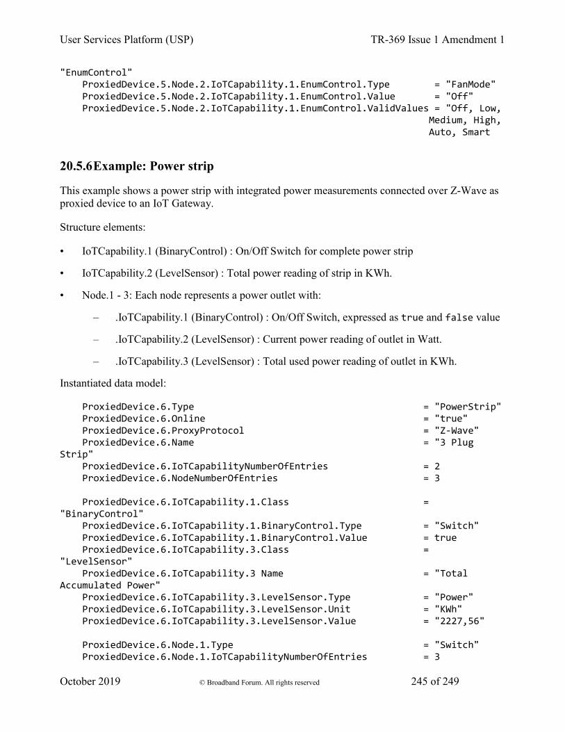
User Services Platform (USP) TR-369 Issue 1 Amendment 1
October 2019 © Broadband Forum. All rights reserved 245 of 249
"EnumControl" ProxiedDevice.5.Node.2.IoTCapability.1.EnumControl.Type = "FanMode" ProxiedDevice.5.Node.2.IoTCapability.1.EnumControl.Value = "Off" ProxiedDevice.5.Node.2.IoTCapability.1.EnumControl.ValidValues = "Off, Low, Medium, High, Auto, Smart
20.5.6 Example: Power strip
This example shows a power strip with integrated power measurements connected over Z-Wave as proxied device to an IoT Gateway.
Structure elements:
• IoTCapability.1 (BinaryControl) : On/Off Switch for complete power strip
• IoTCapability.2 (LevelSensor) : Total power reading of strip in KWh.
• Node.1 - 3: Each node represents a power outlet with:
– .IoTCapability.1 (BinaryControl) : On/Off Switch, expressed as true and false value
– .IoTCapability.2 (LevelSensor) : Current power reading of outlet in Watt.
– .IoTCapability.3 (LevelSensor) : Total used power reading of outlet in KWh.
Instantiated data model:
ProxiedDevice.6.Type = "PowerStrip" ProxiedDevice.6.Online = "true" ProxiedDevice.6.ProxyProtocol = "Z-Wave" ProxiedDevice.6.Name = "3 Plug Strip" ProxiedDevice.6.IoTCapabilityNumberOfEntries = 2 ProxiedDevice.6.NodeNumberOfEntries = 3 ProxiedDevice.6.IoTCapability.1.Class = "BinaryControl" ProxiedDevice.6.IoTCapability.1.BinaryControl.Type = "Switch" ProxiedDevice.6.IoTCapability.1.BinaryControl.Value = true ProxiedDevice.6.IoTCapability.3.Class = "LevelSensor" ProxiedDevice.6.IoTCapability.3 Name = "Total Accumulated Power" ProxiedDevice.6.IoTCapability.3.LevelSensor.Type = "Power" ProxiedDevice.6.IoTCapability.3.LevelSensor.Unit = "KWh" ProxiedDevice.6.IoTCapability.3.LevelSensor.Value = "2227,56" ProxiedDevice.6.Node.1.Type = "Switch" ProxiedDevice.6.Node.1.IoTCapabilityNumberOfEntries = 3
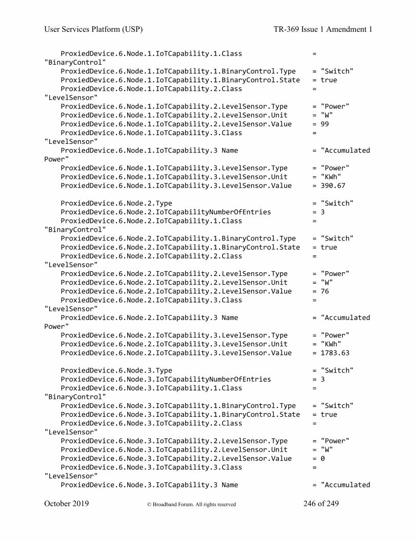
User Services Platform (USP) TR-369 Issue 1 Amendment 1
October 2019 © Broadband Forum. All rights reserved 246 of 249
ProxiedDevice.6.Node.1.IoTCapability.1.Class = "BinaryControl" ProxiedDevice.6.Node.1.IoTCapability.1.BinaryControl.Type = "Switch" ProxiedDevice.6.Node.1.IoTCapability.1.BinaryControl.State = true ProxiedDevice.6.Node.1.IoTCapability.2.Class = "LevelSensor" ProxiedDevice.6.Node.1.IoTCapability.2.LevelSensor.Type = "Power" ProxiedDevice.6.Node.1.IoTCapability.2.LevelSensor.Unit = "W" ProxiedDevice.6.Node.1.IoTCapability.2.LevelSensor.Value = 99 ProxiedDevice.6.Node.1.IoTCapability.3.Class = "LevelSensor" ProxiedDevice.6.Node.1.IoTCapability.3 Name = "Accumulated Power" ProxiedDevice.6.Node.1.IoTCapability.3.LevelSensor.Type = "Power" ProxiedDevice.6.Node.1.IoTCapability.3.LevelSensor.Unit = "KWh" ProxiedDevice.6.Node.1.IoTCapability.3.LevelSensor.Value = 390.67 ProxiedDevice.6.Node.2.Type = "Switch" ProxiedDevice.6.Node.2.IoTCapabilityNumberOfEntries = 3 ProxiedDevice.6.Node.2.IoTCapability.1.Class = "BinaryControl" ProxiedDevice.6.Node.2.IoTCapability.1.BinaryControl.Type = "Switch" ProxiedDevice.6.Node.2.IoTCapability.1.BinaryControl.State = true ProxiedDevice.6.Node.2.IoTCapability.2.Class = "LevelSensor" ProxiedDevice.6.Node.2.IoTCapability.2.LevelSensor.Type = "Power" ProxiedDevice.6.Node.2.IoTCapability.2.LevelSensor.Unit = "W" ProxiedDevice.6.Node.2.IoTCapability.2.LevelSensor.Value = 76 ProxiedDevice.6.Node.2.IoTCapability.3.Class = "LevelSensor" ProxiedDevice.6.Node.2.IoTCapability.3 Name = "Accumulated Power" ProxiedDevice.6.Node.2.IoTCapability.3.LevelSensor.Type = "Power" ProxiedDevice.6.Node.2.IoTCapability.3.LevelSensor.Unit = "KWh" ProxiedDevice.6.Node.2.IoTCapability.3.LevelSensor.Value = 1783.63 ProxiedDevice.6.Node.3.Type = "Switch" ProxiedDevice.6.Node.3.IoTCapabilityNumberOfEntries = 3 ProxiedDevice.6.Node.3.IoTCapability.1.Class = "BinaryControl" ProxiedDevice.6.Node.3.IoTCapability.1.BinaryControl.Type = "Switch" ProxiedDevice.6.Node.3.IoTCapability.1.BinaryControl.State = true ProxiedDevice.6.Node.3.IoTCapability.2.Class = "LevelSensor" ProxiedDevice.6.Node.3.IoTCapability.2.LevelSensor.Type = "Power" ProxiedDevice.6.Node.3.IoTCapability.2.LevelSensor.Unit = "W" ProxiedDevice.6.Node.3.IoTCapability.2.LevelSensor.Value = 0 ProxiedDevice.6.Node.3.IoTCapability.3.Class = "LevelSensor" ProxiedDevice.6.Node.3.IoTCapability.3 Name = "Accumulated

User Services Platform (USP) TR-369 Issue 1 Amendment 1
October 2019 © Broadband Forum. All rights reserved 247 of 249
Power" ProxiedDevice.6.Node.3.IoTCapability.3.LevelSensor.Type = "Power" ProxiedDevice.6.Node.3.IoTCapability.3.LevelSensor.Unit = "KWh" ProxiedDevice.6.Node.3.IoTCapability.3.LevelSensor.Value = 53.26
20.5.7 Example: Battery powered radiator thermostat
This example shows the IoT model for a radiator thermostat with an integrated USP Agent, which is directly controlled.
Structure elements:
• IoTCapability.1 (EnumControl): Operation Mode
• IoTCapability.2 (EnumControl): Auto/Manual Temperature setting
• IoTCapability.3 (EnumControl): Vacation Temperature setting
• IoTCapability.4 (LevelSensor) : Current Temperature
• IoTCapability.5 (LevelSensor): Valve position
• IoTCapability.6 (LevelSensor): Battery status
Note - All temperature settings are modeled as “EnumControl” to define a range between 4 and 23° degC in steps of 0.5° or an “Off” value.
Instantiated data model:
Device.DeviceInfo.Description = "Battery powered radiator thermostat" : Device.IoTCapabilityNumberOfEntries = 6 Device.IoTCapability.1.Class = "EnumControl Device.IoTCapability.1.EnumControl.Type = "ThermostatMode" Device.IoTCapability.1.EnumControl.ValidValues = "Off, Auto, Manual, Vacation" Device.IoTCapability.1.EnumControl.Value = "Auto" # current mode Device.IoTCapability.2.Class = "EnumControl Device.IoTCapability.2.Name = "Desired Temperature" Device.IoTCapability.2.EnumControl.Type = "TemperatureMode" Device.IoTCapability.2.EnumControl.ValidValues = "Off, 4, 4.5, 5.0, 5.5, 6, 6.5, 7, 7.5, 8, 8.5, 9, 9.5, 10, 10.5, 11, 11.5, 12, 12.5, 13, 13.5, 14, 14.5, 15.0, 15.5, 16,
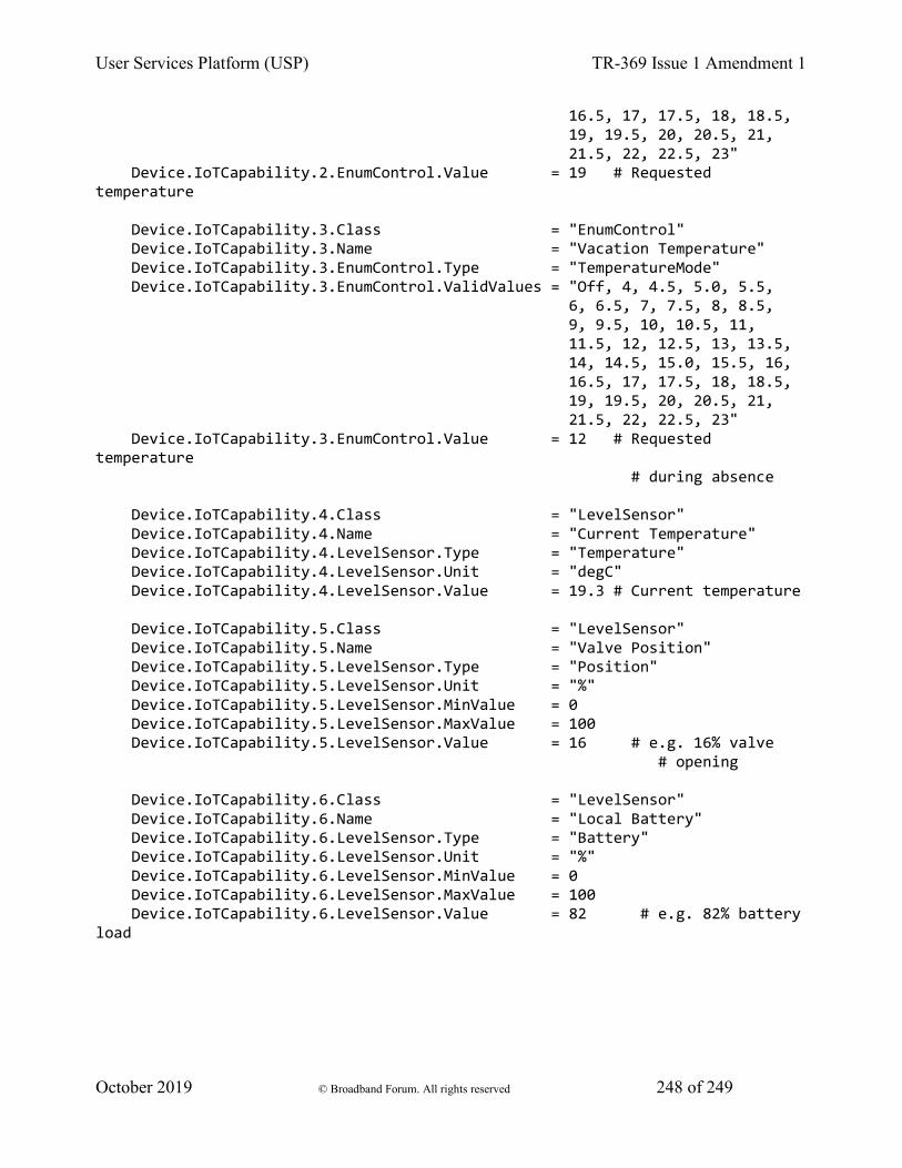
User Services Platform (USP) TR-369 Issue 1 Amendment 1
October 2019 © Broadband Forum. All rights reserved 248 of 249
16.5, 17, 17.5, 18, 18.5, 19, 19.5, 20, 20.5, 21, 21.5, 22, 22.5, 23" Device.IoTCapability.2.EnumControl.Value = 19 # Requested temperature Device.IoTCapability.3.Class = "EnumControl" Device.IoTCapability.3.Name = "Vacation Temperature" Device.IoTCapability.3.EnumControl.Type = "TemperatureMode" Device.IoTCapability.3.EnumControl.ValidValues = "Off, 4, 4.5, 5.0, 5.5, 6, 6.5, 7, 7.5, 8, 8.5, 9, 9.5, 10, 10.5, 11, 11.5, 12, 12.5, 13, 13.5, 14, 14.5, 15.0, 15.5, 16, 16.5, 17, 17.5, 18, 18.5, 19, 19.5, 20, 20.5, 21, 21.5, 22, 22.5, 23" Device.IoTCapability.3.EnumControl.Value = 12 # Requested temperature # during absence Device.IoTCapability.4.Class = "LevelSensor" Device.IoTCapability.4.Name = "Current Temperature" Device.IoTCapability.4.LevelSensor.Type = "Temperature" Device.IoTCapability.4.LevelSensor.Unit = "degC" Device.IoTCapability.4.LevelSensor.Value = 19.3 # Current temperature Device.IoTCapability.5.Class = "LevelSensor" Device.IoTCapability.5.Name = "Valve Position" Device.IoTCapability.5.LevelSensor.Type = "Position" Device.IoTCapability.5.LevelSensor.Unit = "%" Device.IoTCapability.5.LevelSensor.MinValue = 0 Device.IoTCapability.5.LevelSensor.MaxValue = 100 Device.IoTCapability.5.LevelSensor.Value = 16 # e.g. 16% valve # opening Device.IoTCapability.6.Class = "LevelSensor" Device.IoTCapability.6.Name = "Local Battery" Device.IoTCapability.6.LevelSensor.Type = "Battery" Device.IoTCapability.6.LevelSensor.Unit = "%" Device.IoTCapability.6.LevelSensor.MinValue = 0 Device.IoTCapability.6.LevelSensor.MaxValue = 100 Device.IoTCapability.6.LevelSensor.Value = 82 # e.g. 82% battery load

User Services Platform (USP) TR-369 Issue 1 Amendment 1
October 2019 © Broadband Forum. All rights reserved 249 of 249
End of Broadband Forum Technical Report TR-369