Embed Size (px)
Citation preview
- 1 - i3A_IBD2F REV4_0909
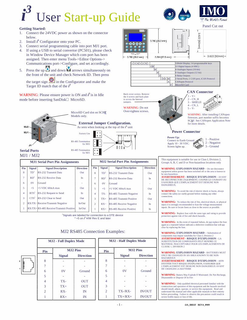
User Start-up Guide
i3
This equipment is suitable for use in Class I, Division 2, Groups A, B, C and D or Non-hazardous locations only WARNING : EXPLOSION HAZARD – Do not disconnect equipment unless power has been switched off or the area is known to be non-hazardous. AVERTISSEMENT - RISQUE D'EXPLOSION - AVANT DE DECONNECTOR L'EQUIPMENT, COUPER LE COURANT OU S'ASSURER QUE L'EMPLACEMENT EST DESIGNE NON DANGEREUX. WARNING : To avoid the risk of electric shock or burns, always connect the safety (or earth) ground before making any other connections. WARNING: To reduce the risk of fire, electrical shock, or physical injury it is strongly recommended to fuse the voltage measurement inputs. Be sure to locate fuses as close to the source as possible. WARNING : Replace fuse with the same type and rating to provide protection against risk of fire and shock hazards. WARNING : In the event of repeated failure, do not replace the fuse again as a repeated failure indicates a defective condition that will not clear by replacing the fuse. WARNING : EXPLOSION HAZARD – Substitution of components may impair suitability for Class I, Division 2 AVERTISSEMENT - RISQUE D'EXPLOSION - LA SUBSTITUTION DE COMPOSANTS PEUT RENDRE CE MATERIAL INACCEPTABLE POUR LES EMPLACEMENTS DE CLASSE 1, DIVISION 2 WARNING : EXPLOSION HAZARD - BATTERIES MUST ONLY BE CHANGED IN AN AREA KNOWN TO BE NON-HAZARDOUS AVERTISSEMENT - RISQUE D'EXPLOSION - AFIN D'EVITER TOUT RISQUE D'EXPLOSION, S'ASSURER QUE L'EMPLACEMENT EST DESIGNE NON DANGEREUX AVANT DE CHANGER LA BATTERIE WARNING : Battery May Explode If Mistreated. Do Not Recharge, Disassemble or Dispose Of In Fire WARNING: Only qualified electrical personnel familiar with the construction and operation of this equipment and the hazards involved should install, adjust, operate, or service this equipment. Read and understand this manual and other applicable manuals in their entirety before proceeding. Failure to observe this precaution could result in severe bodily injury or loss of life.
MicroSD Card slot on SCHF Models only.
Getting Started: 1. Connect the 24VDC power as shown on the connector
below. 2. Install i3 Configurator onto your PC. 3. Connect serial programming cable into port MJ1 port. 4. If using a USB to serial convertor (PC501), please check
in Window Device Manager which com port has been assigned. Then enter menu Tools->Editor Options-> Communications port->Configure, and set accordingly.
5. Press the up and down arrows simultaneously on the front of the unit and check Network ID. Then press
the target sign in the Configurator and make the Target ID match that of the i3
WARNING: Please ensure power is ON and i3 is in Idle mode before inserting SanDisk MicroSD.
Back cover screws. Remove the 4 screws and back plate to access the Internal jumpers.
WARNING: Do not Over-tighten screws.
Power Connector
Power Up: Connect to Earth Ground. Apply 10 - 30 VDC. Screen lights up.
1 - Positive 2 - Negative 3 - Ground
Panel Cut out
3.622 [92mm]
3.622 [92mm
]
i 3 A 1 2 X / 128x64 Display, 14 programmable keys 1 0 12 Digital Inputs (4 HSC)
D 4 Analogue Inputs (10-bit) 0 0 Analogue Outputs (12 bit) 3 6 Relay Outputs - S C H 2 Serial Ports, 1 CAN port, iCAN Protocol
A CANopen Protocol F MicroSD Card
Factory Use
RS-485 Termination for MJ2
RS-485 Termination for MJ1
External Jumper Configuration. As seen when looking at the top of the i3 unit
CAN Connector 1 – V+
2 – CN_H 3 – SHIELD 4 – CN_L 5 – V- WARNING: After installing CANopen firmware, part number suffix becomes SCAF. See CANopen Application Note for more details.
1Signals are labeled for connection to a DTE device * +5 on i3 H/W Rev E and later
MJ1 Serial Port Pin Assignments
Pin Signal Signal Description Direction
8 TD1 RS-232 Transmit Data Out
7 RD1 RS-232 Receive Data In
6 0V Ground -
5 +5 +5 VDC 60mA max Out
4 RTS1 RS-232 Request to Send In
3 CTS1 RS-232 Clear to Send Out
2 RX/TX− Receive/Transmit Negative In/Out
1 RX/TX+ RS-485 Receive/Transmit Positive In/Out
MJ2 Serial Port Pin Assignments
Pin Signal Signal Description Direction
8 TD1 RS-232 Transmit Data Out
7 RD1 RS-232 Receive Data In
6 0V Ground -
5 +5 +5 VDC 60mA max Out
4 TX- RS-485 Transmit Negative In
3 TX+ RS-485 Transmit Positive Out
2 RX− RS-485 Receive Negative In
1 RX+ RS-485 Receive Positive In
Serial Ports MJ1 / MJ2
MJ2 - Full Duplex Mode
Pin MJ2 Pins
Signal Direction
8 - -
7 - -
6 0V Ground
5 - -
4 TX- OUT
3 TX+ OUT
2 RX- IN
1 RX+ IN
MJ2 - Half Duplex Mode
Pin MJ2 Pins
Signal Direction
8 - -
7 - -
6 0V Ground
5 - -
4 - -
3 - -
2 TX-/RX- IN/OUT
1 TX+/RX+ IN/OUT
MJ2 RS485 Connection Examples:

- 2 - i3A_IBD2F REV4_0909
I1 0V
12-24VDC I1 0V
Positive Logic In Negative Logic In
Positive Logic vs. Negative Logic Wiring The i3 can be wired for Positive Logic inputs or
Negative Logic inputs depending on the position of JP1.
I/O Jumper settings are located internally. Remove the 4 screws on the back and lift casing
off to access. Only access when power is removed from the i3. Care must be taken to avoid
over tightening the case screws.
Internal Jumper Configuration
Digital Input
+
–
1 2 3
12 34 56 78
Analogue I/O and Digital I/O
15 - COMMON 6 14 - RELAY 6 13 - COMMON 5 12 - RELAY 5 11 - COMMON 4 10 - RELAY 4 9 - COMMON 3 8 - RELAY 3 7 - COMMON 2 6 - RELAY 2 5 - COMMON 1 4 - RELAY 1 3 - HSC4 / IN12 2 - HSC3 / IN11 1 - HSC2 / IN10
1 - IN1 2 - IN2 3 - IN3 4 - IN4 5 - IN5 6 - IN6 7 - IN7 8 - IN8
9 - HSC1 /IN910 - 0V11 - Ai112 – Ai2 13 – Ai3 14 – Ai4 15 - 0V
1
15 1
15 15
1
12-24VDC
R2 C2 R3 C3
R6 C6
R4 C4 R5 C5
R1 C1
H4
H2 H3
LOAD 230VAC
OR 25VDC
N L
LOAD 230VAC
OR 25VDC
N L
LOAD 230VAC
OR 25VDC
N L
LOAD 230VAC
OR 25VDC
N L
LOAD 230VAC
OR 25VDC
N L
LOAD 230VAC
OR 25VDC
N L
Wiring Example: Positive Logic Digital In / Relay Out
+
+
–
I1 I2 I3 I4
0V A1 A2
0V
I5 I6 I7 I8
A3 A4
H1
12-24VDC
LOOP PWR
20mA
0-10VDC
+
+ –
– +
Expansion I/O Modules
All i3 controllers can have extra analogue and digital I/O added by connecting expansion modules to either MJ1 or MJ2 ports.
For further information on Remote I/O please consult the Remote I/O datasheet, and the i3 Remote I/O tutorial in the downloads section of the IMO website. www.imopc.com/manuals
Input - 4 Channel RTD (0-2000ohm, 0-500ohm, PT100, Ni100, PT1000, Ni1000) iOS / M 4 I P X - D1
Input - 8 Channel DC Current (-20mA to +20mA) iOS / M 8 I C X - D1
Input - 8 Channel DC Voltage (-10V to +10V) iOS / M 8 I V X - D1
Input - 8 Channel Thermocouple (J, K, R, S, B, E, T, N, -/+ 50mV, -/+100mV) iOS / M 8 I T X - D1
Output - 4 Channel DC Voltage / Current (0-20mA, 0-10V) iOS / M 4 O X A - D1
16 Digital Input, 16 Transistor output (0.1A / Channel, 2A / Common) GSL - D T 4 A
16 Relay Output (2A / Channel, 5A / Common) GSL - R Y 2 A
32 Digital Input GSL - D 2 4 A
Basic Options
Note: Other I/O configurations and Fieldbus options are available. Please inquire at IMO. [email protected]
Relay Life Expectancy
Analogue Filtering
A1 A2 A3 A4
In (A1 – A4)
Current Voltage (20 mA) (10 V)
Description JP1 Pins
24V pull up (PNP)
1-2
0V common (NPN)
2-3
15
Channel 0 (4) -20mA
0 - 10V
Ai1 1-2 Open
JP1 Digital DC In / HSC Positive Negative Logic Logic
Default
Default
Registers PWM HSC Stepper
%AQ1 PWM1 Duty Cycle
Start Frequency
%AQ2 (32 bit)
HSC1 Preset Value
Run Frequency
%AQ3 PWM2 Duty Cycle
%AQ4 (32 bit)
HSC2 Preset Value
Accel Count (32 bit)
%AQ5 PWM Prescale
%AQ6 (32 bit)
Run Count (32 bit)
%AQ7 PWM Period
%AQ8 (32 bit) Decel Count (32
bit)
%Q1 Run
%I30 Ready/Done
%I31
Error
Registers
Description
%I1 to %I24 Digital Inputs
%I32 Output Fault
%I25 to %I31 Reserved
%Q1 to %Q16 Digital outputs
%Q17 Clear HSC1 accumulator to 0
Totalizer: Clear HSC2 %Q18
Quadrature 1-2: Accumulator 1 Reset to max – 1
%Q19 Clear HSC3 Accumulator to 0
Totalizer: Clear HSC4 %Q20
Quadrature 3-4: Accumulator 3 Reset to max – 1
%Q21 to %Q32 Reserved
%AI1 to %AI4 Analogue inputs
%AI5, %AI6 HSC1 Accumulator
%AI7, %AI8 HSC2 Accumulator
%AI9, %AI10 HSC3 Accumulator
%AI11, %AI12 HSC4 Accumulator
%AQ1, %AQ2 PWM1 Duty Cycle
%AQ3, %AQ4 PWM2 Duty Cycle
%AQ5, %AQ6 PWM Prescale
%AQ7, %AQ8 PWM Period
%AQ9 to %AQ14 Analogue outputs
Note: Not all i3 units contain the I/O listed in this table.
I/O Register Map
iCAN based expansion I/O is also available on special request. Please inquire at IMO technical support. [email protected]
Wiring Specifications
�For I/O wiring (discrete), use the following wire type or equivalent:
Belden 9918, 18 AWG (0.8 mm2) or larger.
�For shielded Analogue I/O wiring,
use the following wire type or equivalent: Belden 8441, 18 AWG
(0.8 mm2) or larger.
�For CAN wiring, use the following wire type or equivalent: Belden
3084, 24 AWG (0.2 mm2) or larger.
WARNING: Do not short loop power source directly to analogue inputs, more than 35mA load can damage input circuit.

- 3 - i3A_IBD2F REV4_0909
Technical Specifications Digital DC Inputs
Inputs per Module 12 including 4 configurable HSC inputs
Commons per Module 1
Input Voltage Range 12 VDC / 24 VDC
Absolute Max. Voltage 35 VDC Max.
Input Impedance 10 kW
Input Current Positive Logic Negative Logic
Upper Threshold 0.8 mA -1.6 mA Lower Threshold 0.3 mA -2.1 mA
Max Upper Threshold 8 VDC
Min Lower Threshold 3 VDC
OFF to ON Response 1 ms
ON to OFF Response 1 ms
10 kHz Totalizer/Pulse, Edges
5 kHz Frequency/Pulse, Width
HSC Max. Switching Rate
2.5 kHz Quadrature
Digital Relay Outputs Outputs per Module 6 relay
Commons per Module 6
Max. Output Current per Relay 3 A at 250 VAC, resistive
Max. Total Output Current 5 A continuous Max. Output Voltage 275 VAC , 30 VDC
Max. Switched Power 1250 VA, 150 W
Contact Isolation to i3 ground 1000 VAC
Max. Voltage Drop at Rated Current
0.5 V
Expected Life No load: 5,000,000
(See Derating section for chart.) Rated load: 100,000
300 CPM at no load Max. Switching Rate
20 CPM at rated load
Type Mechanical Contact
Response Time One update per ladder scan plus 10 ms
Analogue Inputs Medium Resolution Number of Channels 4
0 - 10 VDC
0 – 20 mA
Input Ranges
4 – 20 mA
Safe input voltage range -0.5 V to +12V
Input Impedance Current Mode: Voltage Mode: (Clamped @ -0.5 VDC to 12 VDC) 100 W 500 k W
Nominal Resolution 10 Bits
%AI full scale 32,000 counts
Max. Over-Current 35 mA
Conversion Speed All channels converted once per ladder scan
Max. Error at 25°C 4-20 mA 1.00%
(excluding zero) 0-20 mA 1.00%
*can be made tighter (~0.25%) by adjusting the digital filter setting to
3.
0-10 VDC 1.50%*
Additional error for temperatures other than 25°C
TBD
160 Hz hash (noise) filter Filtering
1-128 scan digital running average filter
General Specifications Required Power
(Steady State)
130 mA @ 24 VDC
30 A for 1 ms @ 24 VDC – DC Switched Required Power (Inrush)
Primary Power Range 10 – 30 VDC
Relative Humidity 5 to 95% Non-condensing
+/- 35 ppm maximum at 25° C Clock Accuracy
(+/- 1.53 Minutes per Month)
Operating Temperature -10°C to +60°C
Terminal Type Screw Type, 5 mm Removable
Weight 12 oz. (340.19 g)
CE
UL
Approved
For further technical information and a full specification, please consult the Hardware Manual
IMO Precision Controls Ltd 1000 North Circular Rd, Staples Corner, London. NW2 7JP Tel: +44 (0) 208 452 6444, Fax: +44 (0) 208 450 2274, Web: www.imopc.com

- 4 - i3A_IBD2F REV4_0909
OPC or SCADA
Small Extras: RS232 Serial Programming Cable For programming any i3 Model.
PART No: i3PC45
IP65 RJ45 Panel-Mounted Socket Bring either MJ1 or MJ2 ports to the outside world by installing this into a 22.5mm cut-out. PART No: i3PAD USB to RS232 Convertor For PCs without a serial Com Port. Add one with this device.
PART No: PC501
Communication: Ethernet Expansion card Link an i3 to an Ethernet network. Program monitor and debug remotely, or run i3 as a Modbus TCP server.
GSM Modem Expansion Card Send and Receive SMS messages via the i3, dial-up connection over GSM data link for remote programming, debugging etc. Or, use a GPRS always-on data connection ideal for programming, debugging, monitoring and connection to a SCADA package for constant data logging and remote control.
ODIN OPC SERVER (With LOKI data-logger) With no tag limit and 30+ Protocols to choose from (including IMO products, Mitsubishi, Allen Bra dley, Siemens), ODIN can be used with LOKI to log data either to an Excel spreadsheet or an Access database.
Options:
Miscellaneous:
DIN rail mounted SRSI Base and ETS Relay Use the Transistor outputs of the i3 to operate the relay coils to switch up to 6A @ 250VAC.
Part Numbers: SRSI-24AC/DC, ETS-1AN-SL-24VDC
i3 Configurator with Symbol Library Obtain a copy of the i3 Software with a library of colour buttons, pipes, vessels, motors, pumps, fans etc. To enhance the look and feel of applications on the i3C.
Part Numbers: IMO-CD-SUITE
Custom screen overlays Ask at IMO for custom overlays. Overlays are tooled to a customer’s design.
24V DC OUTPUTS 250V AC OUTPUTS
i3A12X/20B05-SOHF SRSI Bases & ETS Relays
Equipment
PART No: i3-M
PART No: i3-E
Panel Point SCADAlite With no tag limit and 30+ Protocols to choose from (including IMO products, Mitsubishi, Allen Bradley, Siemens), a powerful graphical editor, and a VB-based scripting language, Panel-Point allows a PC to become the central data hub of an application.
ETHERNET 10/100 MODBUS TCP/IP
PWM SPEED CONTROL
RS485 MODBUS
iCAN
Remote programming / debugging via VPN to GPRS data enabled i3. Pass-through connection to all devices on the iCAN network.
RS232 Analogue
signal converter
Thermocouple / RTD 4-20mA
INVERTERS
iSMART with Expansion SMT-MODBUS
iOS GSL
HSC SPEED FEEDBACK
SMS/GPRS
PART No: IMO-OPC-SERVER
PART No: PANELPOINT (Developer) PART No: PANELPOINTRT (Runtime)
iSMART via SMT-PC03 cable.
GPS Receiver Locate your i3 Controller anywhere in the world by connecting this device to MJ2 of a unit equipped with a GPRS enabled modem. Part Number: i3-GPS
OPC or SCADA