Embed Size (px)
Citation preview
User’s Guide
Version 1.2
dated 11/27/2017
Gregor Schlechtriem
www.pikoder.com

udpRC4UGV User’s Guide
ii
Contents
Overview 3
Commissioning 5
Setting up the Access Point .............................................................................. 6
Initial Connection .............................................................................................. 8
User Interface 9
Button Control ................................................................................................. 11
Touch Control .................................................................................................. 12
Accelerometer Control.................................................................................... 12
Wheel Control .................................................................................................. 13
Settings 15
APP Settings ..................................................................................................... 16
SSC Settings ...................................................................................................... 19
Hardware setup 21
PiKoder/SSC settings 23

1 Overview
With the udpRC4UAV app and a PiKoder/SSC wRX wlan-receiver you a
control an UGV (Unmanned Ground Vehicle or Rover) equipped with an
autopilot such as the ArduPilot Mega (APM) with your Android™
Smartphone oder Tablet: .The PiKoder/SSC replaces the standard RC re-
ceiver and provides the required input signals for the APM. The applica-
tions can be customized to interface to other autopilots and flight control-
lers also.
The remote function employs the smart phone’s build-in wlan module.The
PiKoder receiver offers an access point (AP) to which the smart device
would connect. Depending on the smart devices’ wlan module spec your
control range could be up to a few hundred meters.
Commissioning the app requires two simple steps:
- Install the app through the Google Play Store and
- Connect your Android device to the Access Point provided by the
receiver following standard Android procedures
These initial steps are described in section 2; after commissioning the app
you simply start the app like any other app on your device. Section 3 pre-
sents the user interface and section 4 illustrates the preferences and settings
of the app.
Exhibit A covers the hardware setup based on the current APM 2.8.
Please note that a PiKoder/SSC firmware release < 2.7 requires a change in
the PiKoder’s default settings for the min. and max. pulse length. Please
refer to exhibit B for more information..


2 Commissioning
The udpRC app is available free of charge in the Play Store; the installation
is started after hitting the button and does not require any user interference.
Please bear in mind though that you have to grant wlan priveliges to the
app.
If you would use the PiKoder/SSC wRX (firmware 2.7 and up) in combina-
tion with an APM 2.8 which was programmed to “Rover Mode” by the
“Mission Planer” then you don’t have to change any settings since this
combination is reflected in the default settings.
If you have changed the network settings of the PiKoder/SSC’s radio then
you would have to also make changes to the App’s preferences as described
in the next section.

udpRC4UGV User’s Guide
6
Setting up the Access Point
The preferences for the name and / or the password of the access point can
be found in the App-settings (see red arrow in the image)
After selecting „App Settings“ the screen changes as shown below. AP pa-
rameters are changed by selecting „APP Settings“.

7
To customize the AP name you would select „Receiver SSID“ and you will
be offered a text input box as shown below. The input of the password
follows a similar fashion after selecting “Receiver Password” .

udpRC4UGV User’s Guide
8
Initial Connection
After installing the App and optionally adjusting the AP settings, you would
have to establich an initial connection between the smart device and your
receiver on Android operating system level (like for every other AP you
intned to use for the first time).
Turn on your receiver, select Android “SETTINGS” on your smart phone,
then „WLAN“. Your receiver should be visible now meaning that e.g.
„PiKoder_wRX“ should show up as active network in the respective list.
Select the AP and connect. After entering your password (the default pass-
word is password the AP would be available to your smart device and ud-
pRC4GUV can now establish a conncetion to receiver when started.
Please note: It is highly recommended that you remove the existing
Android network settings when you upgrade your software to avoid
inconsistent data settings

3 User Interface
After starting udpRC4UGV you will be seeing the main screen which allows
you to select from different user interfaces. Additionaly, this screen would
be your starting point for specific settings. Please note that all control relat-
ed screens are fixed to a landscape format to simplify model control.
To start contolling your model you would hit one of the four buttons selct-
ing your prefered interface. The basic functions and general UI elements are
described in the “Button Control” – section.
Once you selected a user interface, the app will establish a connection to the
receiver. This process will be reflected in status messages such as “Connect-
ing to receiver…” and “Connected to receiver.” (see below).

udpRC4UGV User’s Guide
10
Once the connection is fully established (indicated by the „Connected to
receiver.“ – message) the RC can be operated.

11
Button Control
Button Control offers a very simple user interface: you would control your
model by simply hitting the command button.
Please note that hitting the home button (see red arrow) would always bring
you back to the main menue.
Starting with version 1.2 the app offers a trim function similar to traditional
R/C transmitters to set the neutral position for a channel. When pushing
the gray error buttons initially for one direction (left/ right or for-
ward/backward) the app will retrieve the actual value for this channel from
the PiKoder (thus allowing to store and manage model specific parameter
settings):
Once the channel specific value is known then every push of the arrow but-
ton will change the neutral position by 4 µs giving a range of 250 positions
over the whole range of the servo movement.
udpRC4UGV User’s Guide
12
In addition to the control buttons for the UAV’s movement described
above the user interface offers additional buttons to enable for special func-
tions of the APM 2.8. First off all you can select the „Flight Mode“. The
APM offers three modes for a Rover: AUTO (Execute a pre-programmed
mission), LEARNING (Teach in of a mission by executing the mission
through manual remote control and MANUAL (direct control of the Rover
by the RC). The mode is selected by touching the respective button.
The „CH7-button triggers the receiver to output a preconfigured pulse
length on Channel 7 which the APM interprets as a switch on signal. When
in LEARNING mode then touching the CH7 button stores the current
GPS coordinates as a waypoint.
You can find additional information covering the customization of the APP
in section 4.
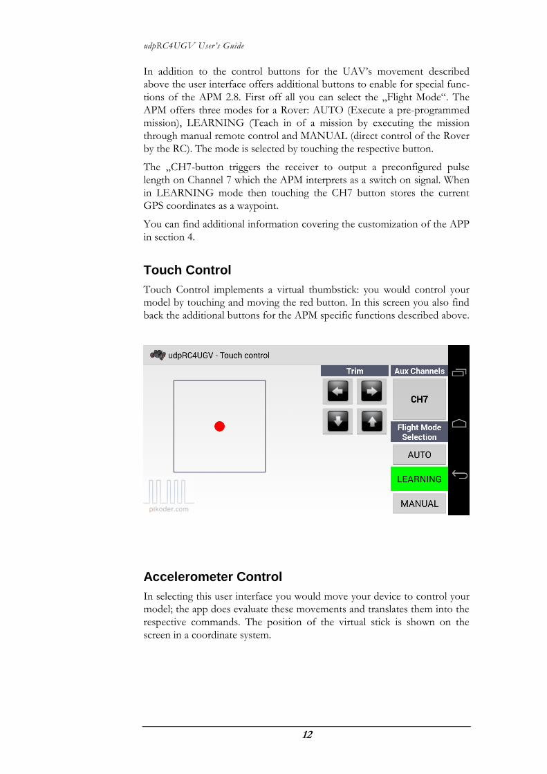
Touch Control
Touch Control implements a virtual thumbstick: you would control your
model by touching and moving the red button. In this screen you also find
back the additional buttons for the APM specific functions described above.
Accelerometer Control
In selecting this user interface you would move your device to control your
model; the app does evaluate these movements and translates them into the
respective commands. The position of the virtual stick is shown on the
screen in a coordinate system.

13
Wheel Control
Wheel Control represents a combination of the Accelerometer and the
Touch Control: directional control is based on movement of your device
similar tot he Accelerometer Control and speed is controlled by a slider.


4 Settings
Your starting point for settings would also be the main screen (s. red ar-
row).
After activating the preference menue you are presented another menue
offering APP Settings, SSC Settings, and the general help link to the
PiKoder web page.

udpRC4UGV User’s Guide
16
APP Settings
In this section you would be able to review basic settings of the app. This
covers the access point’s name (Receiver SSID) and password, a checkbox
for mixing and the setting of pulse lengths to control the APM features.

17
The default SSID (AP name) would be PiKoder_wRX reflecting the
PiKoder/SSC wRX standard configuration. If you are employing another
device then you can adapt the device name by tapping the field.
The setting oft he Receiver Password works in a similar fashion.
Mixing is a specific feature required to control „two motor models“, such as
tanks („Mixing Active“); if your model requires a conventional control (one
channel for direction, one channel for speed control), then uncheck the
box.
The following settings allow you to program the app to the APM needs.
Please note that that you have to mirror these settings in your Mission Plan-
er (please see screen print of Mission Planer).

udpRC4UGV User’s Guide
18

19
The number in „Flight Mode Channel Number“ defines which channel of
your receiver outputs the flight mode information. The default channel fort
he app and the APM is channel 8.
The next three menue items „PWM AUTO mode“, PWM LEARNING
Mode“, and „PWM MANUAL mode“ define which pulse lengths will be
applied to the receiver output when the respective mode is selected. The
default values of the app reflect the default settings of the APM (see screen
dump above).
SSC Settings
SSC Settings are receiver specific settings and are therefore stored in the
PiKoder/SSC’s EEPROM.

udpRC4UGV User’s Guide
20
The udpRC4UGV app features a „fail-safe“-function (in combination with
the PiKoder/SSC wRX): if within a given time frame no new command
would be received then all channels will be set to a neutral position. Since
you can pre-program these neutral positions for your model (refer to
PiKoder/SSC User’s Manual for mode details), you can ensure that a safe
status is warranted (e.g. motors shut off).
The monitoring cycle can stretch from 0.1 to 99.9 seconds. To read the
current receiver setting, you would hit the “Read data” key (s. above). This
command will read the value from the PiKoder store and display it; the
checkbox will be set automatically when a time out value > 0 is found. If
you want to maintain this value then simply hit “Write data”. This will sync
the app and the receiver starting the fail safe function.
If you want to change the value then hit the input filed and the keyboard
would appear allowing you to edit the field content. For disabeling the time
out you would have to uncheck the box. Please note that a change only be-
comes effective after hitting the „Write data“-button.
For enabling the „fail-safe“-funktion you would check the box and then
enter the time out value. As with all other changes you would have to hit
the „Write data“-button to put this change into effect.

A Hardware setup
The setup oft he APM for a rover is documented well
(http://ardupilot.org/rover/docs/apmrover-setup.html). Therefore the
following description will focus on connecting the PiKoder/SSC wRX with
the APM.
Start by replacing the standard RC receiver by the PiKoder/SSC wRX. The
power supply for the PiKoder is provided by the APM following the stand-
ard APM setup, which uses the BEC (Battery Elemination Circuit) of the
ESC (Electronic Speed Controller) to step down the voltage of the rover’s
battery to a range suitable for receivers 4.8 - 6 Volts.
The following picture shows the wiring:

udpRC4UGV User’s Guide
22
In total you would have to hook up four connections using a standard
three-wire servo cables:
1. PiKoder/SSC wRX Channel 1 <-> APM 2.8 INPUT 1
2. PiKoder/SSC wRX Channel 2 <-> APM 2.8 INPUT 3
3. PiKoder/SSC wRX Channel 7 <-> APM 2.8 INPUT 7
4. PiKoder/SSC wRX Channel 8 <-> APM 2.8 INPUT 8
Please bear in mind that this scheme is based on the default configuration
of the PiKoder/SSC wRX as well as the one for the APM. If you had
changed the configuration by e.g. changing the flight mode channel then
you would have to adopt the cabeling respectively.

23
B PiKoder/SSC settings
Controlling an APM with a receiver with a firmware version < 2.7 requires
you to adjust the limits for the minimal and maximal pulse length because
the APM may not execute requests if the pulse lengths are outside of the
predefined limits of the APM.
If you are uncertain about the firmware version of your PiKoder, then you
can connect your receiver to the PCC (PiKoder Control Center) as de-
scribed in the User’s Manual of the PiKoder/SSC wRX and check the re-
lease version as well as the current parameter settings. When using the ud-
pRC4UGV app your PiKoder’s values should equal the one shown in the
following image.