Embed Size (px)
Citation preview

s
Getting Started with HC25Siemens Cellular Engine
Version: 02DocId: HC25_startup_v02Products: HC25
Use
r’s G
uide

Getting Started with HC25
HC25_startup_v02 Page 2 of 57 2007-05-25Confidential / Released
General NotesProduct is deemed accepted by recipient and is provided without interface to recipient’s products. Thedocumentation and/or product are provided for testing, evaluation, integration and information purposes.The documentation and/or product are provided on an “as is” basis only and may contain deficiencies orinadequacies. The documentation and/or product are provided without warranty of any kind, express orimplied. To the maximum extent permitted by applicable law, Siemens further disclaims all warranties,including without limitation any implied warranties of merchantability, completeness, fitness for a partic-ular purpose and non-infringement of third-party rights. The entire risk arising out of the use or perfor-mance of the product and documentation remains with recipient. This product is not intended for use inlife support appliances, devices or systems where a malfunction of the product can reasonably beexpected to result in personal injury. Applications incorporating the described product must be designedto be in accordance with the technical specifications provided in these guidelines. Failure to comply withany of the required procedures can result in malfunctions or serious discrepancies in results. Further-more, all safety instructions regarding the use of mobile technical systems, including GSM products,which also apply to cellular phones must be followed. Siemens or its suppliers shall, regardless of anylegal theory upon which the claim is based, not be liable for any consequential, incidental, direct, indirect,punitive or other damages whatsoever (including, without limitation, damages for loss of business profits,business interruption, loss of business information or data, or other pecuniary loss) arising out the useof or inability to use the documentation and/or product, even if Siemens has been advised of the possi-bility of such damages. The foregoing limitations of liability shall not apply in case of mandatory liability,e.g. under the German Product Liability Act, in case of intent, gross negligence, injury of life, body orhealth, or breach of a condition which goes to the root of the contract. However, claims for damages aris-ing from a breach of a condition, which goes to the root of the contract, shall be limited to the foreseeabledamage, which is intrinsic to the contract, unless caused by intent or gross negligence or based on lia-bility for injury of life, body or health. The above provision does not imply a change on the burden of proofto the detriment of the recipient. Subject to change without notice at any time. The interpretation of thisgeneral note shall be governed and construed according to German law without reference to any othersubstantive law.
CopyrightTransmittal, reproduction, dissemination and/or editing of this document as well as utilization of its con-tents and communication thereof to others without express authorization are prohibited. Offenders willbe held liable for payment of damages. All rights created by patent grant or registration of a utility modelor design patent are reserved.
Copyright © Siemens AG 2007
Trademark noticeMS Windows® is a registered trademark of Microsoft Corporation.
s
User’s Guide: Getting Started with HC25Version: 02
Date: 2007-05-25
DocId: HC25_startup_v02
Status Confidential / Released
Supported Products: HC25

Getting Started with HC25 Contents57
HC25_startup_v02 Page 3 of 57 2007-05-25Confidential / Released
s
Contents
1 Introduction ................................................................................................................. 61.1 Related Documents ........................................................................................... 61.2 Abbreviations ..................................................................................................... 7
2 Installation and Configuration ................................................................................... 82.1 Technical Requirements for Running HC25 on DSB75 ..................................... 82.2 Choosing the Best Installation Strategy ............................................................. 92.3 Installing the Hardware .................................................................................... 102.4 Installation on Windows XP ............................................................................. 12
2.4.1 Installing Connection Manager and Preparing Driver Installation on Windows XP........................................................................................ 12
2.4.2 Installing USB and Ethernet Drivers on Windows XP ......................... 142.5 Installation on Windows Vista .......................................................................... 17
2.5.1 Installing Connection Manager and Peparing Driver Installation on Windows Vista .................................................................................... 17
2.5.2 Installing USB and Ethernet Drivers on Windows Vista...................... 202.6 Special Installation Notes................................................................................. 212.7 Installed Devices and Tools on Windows XP, Windows Vista ......................... 222.8 Uninstalling Drivers and Siemens Connection Manager.................................. 24
2.8.1 Uninstalling Components if HC25 Connects to Windows XP ............. 242.8.2 Uninstalling Components if HC25 Connects to Windows Vista .......... 252.8.3 Uninstalling Components if HC25 is Disconnected............................. 272.8.4 Uninstalling Components of HC25 Preview Releases ........................ 29
2.8.4.1 Uninstalling Earlier Drivers .................................................. 292.8.4.2 Uninstalling Earlier Connection Manager ............................ 29
2.9 Updating HC25 Drivers .................................................................................... 302.9.1 Installing HC25 Drivers from Any Folder on Windows XP .................. 302.9.2 Installing HC25 Drivers from Any Folder on Windows Vista ............... 312.9.3 Installing HC25 Drivers from HC25 Mass Storage.............................. 32
2.10 Customizing Connection Manager and Driver Names..................................... 342.10.1 Customizing the Connection Manager................................................ 342.10.2 Customizing the Displayed Driver Names .......................................... 34
3 Using the HC25 Module ............................................................................................ 363.1 AT Command Interpreter ................................................................................. 363.2 Switching on the HC25 .................................................................................... 373.3 Switching off the HC25 .................................................................................... 373.4 Registering to the Network............................................................................... 373.5 Selecting UMTS or GSM.................................................................................. 383.6 Attaching to the HSDPA or GPRS Network ..................................................... 393.7 Defining the PDP Context ................................................................................ 393.8 Making a Voice Call (MO) ................................................................................ 403.9 Answering a Voice Call (MT) ........................................................................... 403.10 HSDPA or GPRS Data Transfer ...................................................................... 41

Getting Started with HC25 Contents57
HC25_startup_v02 Page 4 of 57 2007-05-25Confidential / Released
s
3.10.1 Data Transfer via Siemens Connection Manager on Windows XP..... 413.10.2 Data Transfer via Siemens Connection Manager on Windows Vista . 423.10.3 Data Transfer via Dial-Up Network ..................................................... 45
3.10.3.1 Local Echo Settings ............................................................ 46
4 Appendix I.................................................................................................................. 474.1 Adding and Configuring a New Dial-Up Network Connection.......................... 47
4.1.1 Creating a New Dial-up Network Connection ..................................... 474.1.2 Configuring a Dial-up Network Connection......................................... 50
5 Appendix II................................................................................................................. 535.1 Configuring DSB75 Support Board and Adapter Board................................... 53
6 Index........................................................................................................................... 57

Getting Started with HC25 Figures57
HC25_startup_v02 Page 5 of 57 2007-05-25Confidential / Released
s
Figures
Figure 1: DSB75 Support Board with mounted adapter board and mini antenna cable 10Figure 2: DSB75 Support Board with HC25 module and accessories connected......... 11Figure 3: Deleting obsolete HC25 driver files, folders and subfolders .......................... 32Figure 4: Folder tree of HC25 driver package............................................................... 33Figure 5: Adapter board - switch settings...................................................................... 53Figure 6: Mounting HC25 to DSB75 (exploded view )................................................... 54Figure 7: DSB75 Support Board - switches, connectors, LEDs (overview)................... 55Figure 8: Adapter board schematic ............................................................................... 56
HC25_startup_v02 Page 6 of 57 2007-05-25Confidential / Released
Getting Started with HC251 Introduction9
s
1 Introduction
HC25 is the first Siemens wireless module to offer Tri-band UMTS and Quad-Band GSM capa-bility on the same device. The benefit is that the HC25 includes 3.6 Mbit/s HSDPA capability ina UMTS network and also all common mobile connectivity features like voice, short messages,GPRS and EGPRS.
The HC25 modules need to connect to an adequate host device, such as the DSB75 SupportBoard. Designed to help application manufacturers and system integrators to test and developtheir HC25 host application, the DSB75 provides all interfaces and peripherals needed to runthe HC25.
The purpose of this document is to guide you through the process of connecting the hardware,installing the software on a Windows XP or Windows Vista system, and, last but not least, mak-ing the first data transmission via UMTS and HSDPA.
1.1 Related Documents
Documents supplied with HC25[1] HC25 Hardware Interface Description[2] HC25 AT Command Set [3] HC25 Release Notes[4] Application Note 02: Audio Interface Design for HC25[5] Application Note 16: Updating HC25 Firmware[6] Application Note 22: Using TTY / CTM Equipment with HC25[7] Application Note 26: Power Supply for Wireless Applications[8] Application Note 37: GPS Antenna Integration for HC25[9] Application Note 39: USB Interface Description[10] Application Note 40: Thermal Solutions for HC25 Applications[11] Remote SAT User’s Guide for HC25
Other related documents[12] DSB75 Development Support Board Hardware Description
Designed for a wide range of Siemens wireless modules this document is ready for down-load on the Siemens Website: http://www.siemens.com/wm

HC25_startup_v02 Page 7 of 57 2007-05-25Confidential / Released
Getting Started with HC251.2 Abbreviations9
s
1.2 Abbreviations
Abbreviation Description
APN Access Point Name
CHAP Challenge Handshake Authentication Protocol
DSB75 Short for DSB75 Development Support Board
GPRS General Packet Radio Service
HSDPA High-Speed Downlink Packet Access
IP Internet Protocol
ME Mobile Equipment
MO Mobile Originated
MT Mobile Terminated
PAP Password Authentication Protocol
PDP context Packet Data Protocol context
TA Terminal Adapter
TE Terminal Equipment
UICC Universal Integrated Circuit Card
UMTS Universal Mobile Telecommunication System
URC Unsolicited Result Code

HC25_startup_v02 Page 8 of 57 2007-05-25Confidential / Released
Getting Started with HC252 Installation and Configuration9
s
2 Installation and Configuration
2.1 Technical Requirements for Running HC25 on DSB75
• Windows XP or Windows Vista computer, minimum USB 1.1 connector
• HC25 module
• HC25 driver package either contained in - the HC25 mass storage = delivery default for HC25 modules shipped from factory;- or in an extra ZIP file = driver update packages delivered separately. File name:
"HC25_<release>_conman_install.zip" . Please refer to Section 2.2 to decide which installation method to choose.
• If drivers from earlier HC25 preview releases and test samples are still installed be sure touninstall them first. See Section 2.8.4.
• Local Administrator Privileges on the particular Windows computer are required to install,uninstall and use the Siemens Connection Manager.
• If you wish to customize the names of the device drivers displayed in the Windows DeviceManager and/or the name of Connection Manager, you can edit the required strings insome of the provided files before installing the driver package. For details see Section 2.10.
• Appropriate hardware platform, e.g. the reference evaluation kit delivered by Siemens fortesting and developing HC25 applications:- DSB75 Support Board providing the application interface between the HC25 USB port
and the computer's USB port. - Adapter for mounting the HC25 module onto the DSB75- 9 to 15 Volts power supply applied at the DSB75 for powering up the DSB75 and the con-
nected HC25 module- 1 mini antenna cable (50 Ohms) from the RF antenna connector ( Hirose U.FL) on the
HC25 module to the Hirose U.FL on the DSB75; 1 external RF antenna connecting to theSMA connector of the DSB75 (product name: SMARTEQ MiniMag), both delivered withDSB75
- Metal plate for grounding the external RF antenna, min. 20 cm x 20 cm- Optional: Handset, eg. Handset for Siemens products from Votronic delivered with
DSB75
• USB cable
• Appropriate host application to control the USB ports under Windows, for example Hyper-terminal integrated in Windows XP.
• UICC card

HC25_startup_v02 Page 9 of 57 2007-05-25Confidential / Released
Getting Started with HC252.2 Choosing the Best Installation Strategy9
s
• Service provider settings for access to the GPRS and HSDPA services, as a rule the fol-lowing:- APN (network operator specific Name of Access Point that connects the GSM network to
the Internet)- Primary and secondary DNS- IP address (DHCP or static)- QoS settings- User name and password
• HC25 offers two ways to access the GPRS or HSDPA networks: either the Siemens Wire-less Ethernet Adapter controlled by the Siemens Connection Manager or a dial-up networkconnection set up via the Siemens HSDPA USB Modem. For details see Section 3.10.
• Make sure to operate the HC25 always with the UICC card inserted in the card reader anda valid SIM PIN entered. This is because most AT commands require SIM PIN authentica-tion.
2.2 Choosing the Best Installation Strategy
The sequence of the installation steps depends on where the supplied driver package islocated:
1. HC25 modules shipped from factory have the driver package located on the mass storage.Thus, the standard installation procedure is designed to be launched directly from the massstorage. Overview of installation steps: First connect the HC25 module to the DSB75 and start thecomputer (see Section 2.3). Then install the Siemens Connection Manager to prepare thedriver installation (see Section 2.4.1 for Windows XP or Section 2.5.1 for Windows Vista).Finally install the composite device drivers (see Section 2.4.2 for Windows XP or Section2.5.2 for Windows Vista).
2. Latest driver updates are contained in the "HC25_<release>_conman_install.zip" file, usu-ally ready for download from http://www.siemens.com/wm. If you wish to update to the lat-est driver versions, you have the following options:
- Installing the drivers from the mass storage Overview of installation steps: First uninstall the existing drivers from the Windows com-puter. Switch off or unplug the module. Switch on or replug the module. Delete all old fileslocated in the mass storage and replace them with the new files, using exactly the samedirectory tree. Switch off or unplug the module. Switch on or replug the module. Installthe Siemens Connection Manager and the composite device drivers from the mass stor-age. If the HC25 module is intended to be inserted into more than one device take care thatthe mass storage always contains the latest drivers.See Section 2.9.3 for details.
- Installing the drivers from any folder inside the Windows systemOverview of installation steps: First uninstall the existing drivers from the Windows com-puter. Switch off or unplug the module. Install the Siemens Connection Manager. Switchon or replug the module. Install the composite device drivers.See Section 2.9.2 for details.

HC25_startup_v02 Page 10 of 57 2007-05-25Confidential / Released
Getting Started with HC252.3 Installing the Hardware11
s
2.3 Installing the Hardware
To properly connect the HC25 module and all accessories to the DSB75 Support Board followthese steps: • Check that all switches of the DSB75 Support Board are set as described in Chapter 5. See
also Figure 6 which shows an exploded view of all parts.• Connect the one end of the mini antenna cable to the RF antenna connector (Hirose U.FL)
located on the module's top side.• Mount the HC25 module upside down onto the 50-pin board-to-board connector of the
adapter board. Use the supplied M2 screws and nuts to screw the module to the adapter.• Attach the adapter board to the 80-pin header located on the DSB75. Take gentle care that
all pins are aligned correctly, then press down evenly on the adapter board until it is firmlyseated. Use the supplied M3 screw and bolt to secure the adapter board to the DSB75 Sup-port Board.
• Connect the other end of the mini antenna cable to the Hirose U.FL connector of theDSB75.
• Screw the external antenna (MiniMag) into the SMA connector on the DSB75. To improvethe antenna performance use the metal plate for grounding. The external antenna shouldbe positioned in the center of the metal plate.
• Connect the Western plug of the handset to the Western jack on the DSB75.• Connect the power cables to the red (BATT+) and black (Ground) connectors of the DSB75. • Plug the USB cable to the computer's USB port and to the USB port of the DSB75. Press
the IGT key of the DSB75 to switch on the HC25 module. Start your Windows computer.• To continue see Section 2.4 for Windows XP or Section 2.5 for Windows Vista.
Figure 1: DSB75 Support Board with mounted adapter board and mini antenna cable
USB connector
Power supply
DSB75 Support Board
Mini antenna cable
Adapter board
50-pin board-to-board connector
Hirose U.FL connector
SMA connector
UICC/SIM readerWestern jack for handset
IGT key (left) and EMERG_OFF key (right)

HC25_startup_v02 Page 11 of 57 2007-05-25Confidential / Released
Getting Started with HC252.3 Installing the Hardware11
s
Figure 2: DSB75 Support Board with HC25 module and accessories connected

HC25_startup_v02 Page 12 of 57 2007-05-25Confidential / Released
Getting Started with HC252.4 Installation on Windows XP13
s
2.4 Installation on Windows XP
2.4.1 Installing Connection Manager and Preparing Driver Installa-tion on Windows XP
After switching on or plugging the module, you will see the New Hardware Found Wizard com-ing up three times, requesting you to install the software for HC25 VCOM, HC25 NET andHC25 Modem. Click Cancel in each dialog.
At the same time the module enumerates as mass storage device in your Windows XP system,showing up as a Removable Disk assigned to the next free drive in the Windows Explorer. Anadditional Windows system tray icon also indicates the mass storage device.
The wizard’s error message that pops up in the Windows taskbar shall be ignored. The instal-lation will proceed automatically. Note: If the installation fails to start automatically after you have canceled the three New Hard-ware Found Wizards simply navigate to the mass storage drive (= Removable Disk in the Win-dows Explorer) and double-click the provided “autorun.exe“ file.
HC25_startup_v02 Page 13 of 57 2007-05-25Confidential / Released
Getting Started with HC252.4 Installation on Windows XP13
s
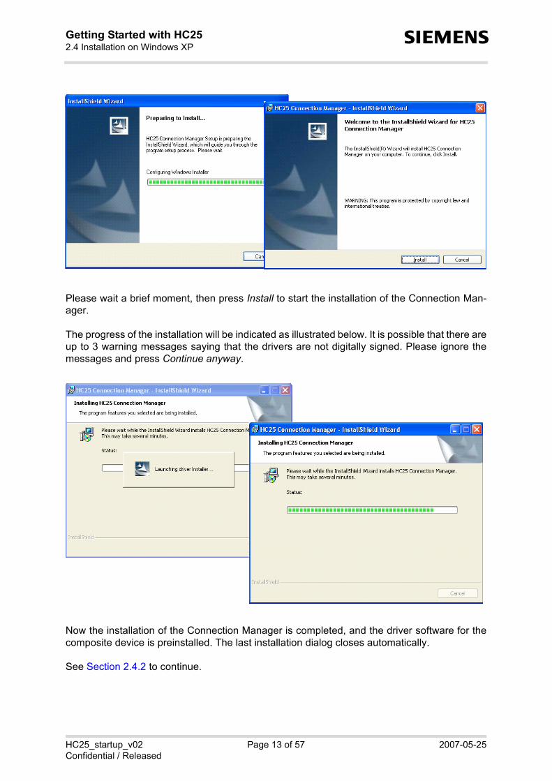
Please wait a brief moment, then press Install to start the installation of the Connection Man-ager.
The progress of the installation will be indicated as illustrated below. It is possible that there areup to 3 warning messages saying that the drivers are not digitally signed. Please ignore themessages and press Continue anyway.
Now the installation of the Connection Manager is completed, and the driver software for thecomposite device is preinstalled. The last installation dialog closes automatically.
See Section 2.4.2 to continue.

HC25_startup_v02 Page 14 of 57 2007-05-25Confidential / Released
Getting Started with HC25 35
s
2.4.2 Installing USB and Ethernet Drivers on Windows XP
HC25 is installed as a composite device that comprises three virtual devices, one by one addedto your Windows XP system:• Siemens HC25 USB Com Port driver• Siemens HC25 Wireless Ethernet Adapter driver• Siemens HC25 HSDPA USB Modem driver
During the installation, the HC25 USB interface will be assigned two virtual COM ports, one forthe virtual modem port and one for the virtual application port. Windows will automatically allo-cate the next available COM port to each virtual interface.
Once the Siemens Connection Manager installation has completed Windows detects the HC25as a new USB composite device.
The Found New Hardware Wizard willstart. Click Next to proceed with theinstallation of the "Siemens HC25 USBCom Port".
The progress of the driver installation isindicated. There might be a warning messagesaying that the driver is not digitallysigned. Please ignore the message andpress Continue anyway.
Click Finish to complete the installation of the "Siemens HC25 USB Com Port".

HC25_startup_v02 Page 15 of 57 2007-05-25Confidential / Released
Getting Started with HC25 35
s
Now the installation of the "SiemensHC25 Wireless Ethernet Adapter"will start. Click Next.
The progress of the driver installa-tion is indicated.
There might be a warning messagesaying that the driver is not digitallysigned. Please ignore the messageand press Continue anyway.
Press Finish to complete the "Sie-mens HC25 Wireless EthernetAdapter" installation.

HC25_startup_v02 Page 16 of 57 2007-05-25Confidential / Released
Getting Started with HC25 35
s
Now the installation of the "SiemensHC25 HSDPA USB Modem" willstart. Click Next.
The progress of the driver installa-tion is indicated.
There might be a warning messagesaying that the driver is not digitallysigned. Please ignore the messageand press Continue anyway.
Press Finish to complete the "Sie-mens HC25 HSPDA USB Modem"installation.
At this point the installation of allthree virtual devices is completed.Windows XP notifies you that thehardware is ready to use.

HC25_startup_v02 Page 17 of 57 2007-05-25Confidential / Released
Getting Started with HC252.5 Installation on Windows Vista35
s
2.5 Installation on Windows Vista
2.5.1 Installing Connection Manager and Peparing Driver Installa-tion on Windows Vista
If you plug the HC25 module and install the HC25 drivers the first time, the New HardwareFound wizard will pop up three times requesting you to install the software for the virtualdevices HC25 VCOM, HC25 NET and HC25 MODEM. Click Cancel in each dialog. If you rein-stall the drivers these dialogs will usually not appear.
At the same time the module enumerates as a mass storage device in your Windows Vista sys-tem, showing up as a Removable Disk assigned to the next free drive in the Windows Explorer.An additional Windows system tray icon also indicates the mass storage device.
If Autoplay is enabled on the computer you will be promptedto select "Run autorun.exe". If the installation does not start automatically, due to thespecific computer configuration, navigate to the mass stor-age drive and double-click the provided "autorun.exe" file.

HC25_startup_v02 Page 18 of 57 2007-05-25Confidential / Released
Getting Started with HC252.5 Installation on Windows Vista35
s
The autorun.exe icon starts to blink in the task bar of Windows Vista while showing this mes-sage:
"autorun.exe is requesting your permission"
Please click on the icon. A popup window "User Account Control" will show: "An unidentifiedprogram wants access to your computer". Please press "Allow" to start the HC25 installer onWindows Vista.
The installer will start to pre-pare the installation.
Now the HC25 ConnectionManager can be set up.Press Install.

HC25_startup_v02 Page 19 of 57 2007-05-25Confidential / Released
Getting Started with HC252.5 Installation on Windows Vista35
s
The progress of the installa-tion is indicated.
It is possible that there are up to 3 warningmessages saying that the drivers are notdigitally signed. Please ignore the mes-sages and select the option Install thisdriver software anyway.
The HC25 Connection Man-ager setup is completed.The last installation dialogbox closes automatically.See Section 2.5.2 to con-tinue.

HC25_startup_v02 Page 20 of 57 2007-05-25Confidential / Released
Getting Started with HC252.5 Installation on Windows Vista35
s
2.5.2 Installing USB and Ethernet Drivers on Windows Vista
Once the HC25 Connection Manager installation has completed the HC25 will be set up as acomposite device comprising three virtual devices:• Siemens HC25 USB Com Port driver• Siemens HC25 Wireless Ethernet Adapter driver• Siemens HC25 HSDPA USB Modem driver
An icon will show up in the Windows Vistatask bar to indicate the progress of the driverinstallation.
Finally, the icon indicates that all devices areready to use.

HC25_startup_v02 Page 21 of 57 2007-05-25Confidential / Released
Getting Started with HC252.6 Special Installation Notes35
s
2.6 Special Installation Notes
If the installation does not work as expected, additional steps may be required, usually depend-ing on the configuration of the Windows XP or Windows Vista computer.
HC25 does not show up as removable disk• If the HC25 is not visible as removable disk
(mass storage device) when connected andswitched on the first time, it is possible thatthe computer is configured to search theInternet for Windows updates. As a result,Windows is waiting for additional useraction.
• To avoid this scenario, it is recommendedto switch off this option before trying toinstall the HC25.
Connection Manager installed, but driver installation does not start• If the Connection Manager installation completes successfully as explained in Section 2.4.1
(Windows XP) or Section 2.5.1 (Windows Vista), but the driver installation does not start asshown in Section 2.4.2 (Windows XP) or Section 2.5.2 (Windows Vista), it is possible thatthe HC25 has failed to change from mass storage device to composite device functionality.
• In this case, please stop the mass storage function manually. To do so, right-click the“Removable Disk“ drive and select Eject. The installation should proceed according to Sec-tion 2.4.2 or Section 2.5.2.If the HC25 still shows up as removable device, point to the associated Windows systemtray icon, and select Stop from the resulting Safely Remove Hardware box. Then unplugand replug the USB cable.

HC25_startup_v02 Page 22 of 57 2007-05-25Confidential / Released
Getting Started with HC252.7 Installed Devices and Tools on Windows XP, Windows Vista35
s
2.7 Installed Devices and Tools on Windows XP, Windows Vista
After successful installation, the HC25 module isset up as composite device comprising the virtualdevices listed below. On Windows XP and Win-dows Vista, you can use the Device Manager tocheck that all components are properly installedand configured.
Siemens HC25 HSDPA USB Modem• AT command and data interface, also referred
to as "Modem" interface if queried using the AT^SQPORT command. • Intended particularly for HSDPA and GPRS data connections.• The virtual COM port Windows has assigned to this interface is listed in the Device Manager
under Modems and under Control Panel | Phone and Modem Options.• The port number can be gathered from the property pages. This COM port can be used to
set up dial-up network connections. The bit rate set by default on the modem property pageis not relevant for USB and can be left unchanged. On the Advanced tab you can put thecommand string used to define the PDP context for your GPRS / HSDPA provider. See alsoSection 3.7.
HC25_startup_v02 Page 23 of 57 2007-05-25Confidential / Released
Getting Started with HC252.7 Installed Devices and Tools on Windows XP, Windows Vista35
s
Siemens HC25 USB Com Port• AT command interface, also referred to as "Application" interface if queried using the
AT^SQPORT command.• Mainly intended for controlling the HC25 module, for receiving URCs, also for sending,
receiving, writing and reading short messages. Not intended as data interface for HSDPAand GPRS.
• The virtual COM port Windows has assigned to this port is listed in the Device Managerunder Ports (COM&LPT).
Siemens HC25 Wireless Ethernet Adapter• Wireless network adapter intended for HSDPA and GPRS data connections. • Listed in the Device Manager under Network adapters.• Software controlled by the Siemens Connection Manager. To open the program in Win-
dows XP, click Start, point to Programs, select Siemens, select HC25 HSDPA USB Modemand click HC25 Connection Manager. See Section 3.10 and Section 3.10.1 (Windows XP)or Section 3.10.2 (Windows Vista) for details on how to set up a connection.

HC25_startup_v02 Page 24 of 57 2007-05-25Confidential / Released
Getting Started with HC252.8 Uninstalling Drivers and Siemens Connection Manager35
s
2.8 Uninstalling Drivers and Siemens Connection Manager
The steps required to remove the installed HC25 components vary depending on whether themodule switched on or off.
The procedures are almost the same for Windows XP and Windows Vista except for the minordifferences described below.
2.8.1 Uninstalling Components if HC25 Connects to Windows XP
1. Ensure that the module is connected to the computer’s USB port and switched on.
2. Close all HC25 applications, for example the HC25 Connection Manager or terminal pro-gram(s) connected to the virtual USB port(s).
3. Open the Control Panel. Click Add or Remove Programs and select HC25 Connection Man-ager. Press Remove to select the uninstaller of the Connection Manager and the HC25 driv-ers.
4. Press Yes to start the uninstaller.
5. The HC25 Connection Manager and all HC25 drivers will be removed.

HC25_startup_v02 Page 25 of 57 2007-05-25Confidential / Released
Getting Started with HC252.8 Uninstalling Drivers and Siemens Connection Manager35
s
2.8.2 Uninstalling Components if HC25 Connects to Windows Vista
1. Ensure that the module is connected to the computer’s USB port and switched on.
2. Close all HC25 applications, for example the HC25 Connection Manager or the host appli-cation(s) connected to the virtual USB port(s).
3. Open the Control Panel. Click Programs and Features and point to the HC25 ConnectionManager. Double-click or right-click HC25 Connection Manager to start the uninstaller, thenclick Yes to confirm the resulting uninstall message.
4. A popup window named User Account Control will display the message "An unidentifiedprogram wants access to your computer". Press the Allow button to launch the uninstalleron Windows Vista.
5. Wait a brief moment until the HC25Connection Manager closes and alldrivers are removed.

HC25_startup_v02 Page 26 of 57 2007-05-25Confidential / Released
Getting Started with HC252.8 Uninstalling Drivers and Siemens Connection Manager35
s
6. The Found New Hardware wizard will pop up three times because, after driver clean-up,Windows Vista starts searching for new drivers. Press Cancel to abort the search.
In some cases, the Found NewHardware wizards may indicate"Unknown Device" instead of HC25VCOM, HC25 NET and HC25MODEM. The procedure is thesame - simply press Cancel threetimes.
7. The HC25 Connection Manager and the HC25 drivers are removed now. Only the two files files hc25usbser.sys“ and “hc25usbnet.sys are left unchanged in the..\WINDOWS\system32\drivers folder. Yet, this is no problem, as they will be overwrittennext time you re-install the drivers.

HC25_startup_v02 Page 27 of 57 2007-05-25Confidential / Released
Getting Started with HC252.8 Uninstalling Drivers and Siemens Connection Manager35
s
2.8.3 Uninstalling Components if HC25 is Disconnected
If disconnected or switched off, the HC25 module is not visible on the Windows XP or WindowsVista computer unless you enable the operating system to show hidden devices. The purposeof this section is to describe how to uninstall HC25 components in such case. The dialog boxesshow Windows Vista, but Windows XP is quite similar.
1. Remove the HC25 Connection Manager as described in Section 2.8.1. As a result, the Connection Manager software will be uninstalled, but the HC25 drivers arenot.
2. Although not visible, the HC25 drivers are still blocking two virtual COM ports. To free theports hidden devices must be shown as follows: On Windows XP, open the Control Panel, click System and select the Advanced tab. On Windows Vista, open the Control Panel, select System and Maintenance, click Systemand select Advanced system settings on the left panel of the dialog box. Then press the Environment Variables button. In the resulting dialog box point to the Sys-tem variables section and press the New button. Enter the new system variable "DEVMGR_SHOW_NONPRESENT_DEVICES" and setvalue "1".

HC25_startup_v02 Page 28 of 57 2007-05-25Confidential / Released
Getting Started with HC252.8 Uninstalling Drivers and Siemens Connection Manager35
s
3. Open the Device Manager (from Control Panel). Note that if the Device Manager is alreadyopen you need to close and re-open it to update the status of the devices. From the Viewmenu select Show hidden devices.
4. All hidden virtual HC25 devices are listed now. Right-click each device, one by one, selectUninstall and confirm the resulting uninstall messages. The example shows how to uninstall the Siemens HC25 USB Com Port. The SiemensHC25 Wireless Ethernet Adapter and the Siemens HC25 HSDPA USB Modem must beuninstalled in the same way.

HC25_startup_v02 Page 29 of 57 2007-05-25Confidential / Released
Getting Started with HC252.8 Uninstalling Drivers and Siemens Connection Manager35
s
2.8.4 Uninstalling Components of HC25 Preview Releases
The following procedures apply only to drivers of earlier HC25 releases supplied as previewsamples for testing only. These drivers were available only for Windows XP.
2.8.4.1 Uninstalling Earlier Drivers
1. Under Windows XP, open the Device Manager andselect the drivers as described in Section 2.7. Keepin mind that the drivers are listed in the Device Man-ager only when the module is switched on. Right-click the driver and, from the resulting menu, selectUninstall.
If the module is disconnected first follow the stepsprovided in Section 2.8.3 and enable the DeviceManager to show hidden devices.
2. Under ..\WINDOWS\system32\drivers remove thetwo files “hcusbser.sys“ and “hcusbnet.sys“. (Please note that the newly installed HC25drivers will now be set up as “hc25usbser.sys“ and “hc25usbnet.sys).
3. Under ..\WINDOWS\INF check for old “oem*.inf“ and “oem*.pnf“ files and remove all filesrelated to earlier customer samples.To do so, open the currently installed “oem*.inf“ file(s) and compare the content with the“hcser.inf“, “hcnet.inf“and "hcmdm.inf" supplied with the latest release. All “oem*.inf“ andassociated “oem*.pnf“ files based on information from old “hcser.inf“, “hcnet.inf“ and“hcmdm.inf“files must be removed. An easy way to compare the content of these files is checking the information given in the[Siemens] section, such as the two examples shown below:Examples:
2.8.4.2 Uninstalling Earlier Connection Manager
Old versions of the Siemens Connection Manager were installed in Windows XP under Pro-gram Files | Siemens | ConnectionManager. To uninstall the program simply remove the "con-man.exe" file.Any shortcuts and icons must be deleted manually.
[SIEMENS]%hcwwan.DeviceDesc_hc1% = hcwwan.ndi, USB\VID_0681&PID_0040&MI_01
[SIEMENS]%hcwwan.DeviceDesc_hc1% = hcwwan.ndi, USB\VID_05C6&PID_7001&MI_01

HC25_startup_v02 Page 30 of 57 2007-05-25Confidential / Released
Getting Started with HC252.9 Updating HC25 Drivers35
s
2.9 Updating HC25 Drivers
Driver updates are contained in a ZIP file named "HC25_<release>_conman_install.zip". TheZIP file is either delivered separately or ready for download from http://www.siemens.com/wm.
The following sections describe how to install the new drivers either from any location on a Win-dows XP computer (see Section 2.9.1) or a Windows Vista computer (see Section 2.9.2) orfrom the HC25 mass storage (see Section 2.9.3).
2.9.1 Installing HC25 Drivers from Any Folder on Windows XP
1. Switch off the HC25 module or unplug the USB cable.2. Copy or unpack the new driver package to any folder on your Windows XP computer.
The folder tree must be the same as shown in Section 2.9.3, Figure 4. Therefore, do notcopy or unpack the files into one folder only. Recommendation: When you extract the supplied "HC25_<release>_conman_install.zip"take care to retain the folders and subfolders stored in the ZIP archive.
3. Double-click the "autorun.exe" file from the dezipped driver package.4. The installation of the Siemens Connection Manager will start and, at the same time, the
composite device driver software will be preinstalled. Simply follow the screens describedin Section 2.4.1. The last installation dialog closes automatically.
5. Now, switch on the HC25 module or replug the USB cable. 6. Windows will detect the HC25 module as a new device. The New Hardware Found wizard
pops three times, prompting you to install the following devices:- Siemens HC25 USB Com Port driver- Siemens HC25 Wireless Ethernet Adapter driver- Siemens HC25 HSDPA USB Modem driverTo do so, follow the screens described in Section 2.4.2, i.e. simply press Next in each dia-log, using the option Install the software automatically (Recommended).
Keep in mind that, before the composite device drivers are installed, the HC25 enumerates asmass storage if the factory default settings of the AT^SUSB command are left unchanged:parameter <start> equals "MdmNet" and timeout <mnto> equals 10 seconds. The mass stor-age is not needed, but you may be required to take the following precautions:
- If the installation of all three drivers completes before the <mnto> timeout expires themass storage will be deactivated automatically. But as 10 seconds are typically notenough for all three drivers it is very likely that the HC25 enumerates as mass storageduring the installation. As a result, the driver installation (step 6 above) may be halted, forexample after the first (or already the second) driver was set up. Yet, this is nothing toworry about - all you need to do is manually ejecting the mass storage. So, right-click theRemovable Disk drive inside the Windows Explorer and select Eject. This will deactivatethe mass storage functionality, and at the same time, cause the New Hardware Foundwizards for the next one or two drivers to pop up.
- If you prefer to install driver updates always from a location other than the HC25 massstorage, you can disable the <mnto> timeout of the AT^SUSB command (set 0 seconds).The setting is non-volatile. For details on AT^SUSB please refer to [2].
IMPORTANT: To avoid mixing up the driver packages located in the mass storage and in anyother folder be sure to run the "autorun.exe" only from the new dezipped driver package.

HC25_startup_v02 Page 31 of 57 2007-05-25Confidential / Released
Getting Started with HC252.9 Updating HC25 Drivers35
s
2.9.2 Installing HC25 Drivers from Any Folder on Windows Vista
1. Switch off the HC25 module or unplug the USB cable.2. Copy or unpack the new driver package to any folder on your Windows XP computer.
The folder tree must be the same as shown in Section 2.9.3, Figure 4. Therefore, do notcopy or unpack the files into one folder only. Recommendation: When you extract the supplied "HC25_<release>_conman_install.zip"take care to retain the folders and subfolders stored in the ZIP archive.
3. Double-click the "autorun.exe" file from the dezipped driver package.4. The installation of the Siemens Connection Manager will start and, at the same time, the
composite device driver software will be preinstalled. Simply follow the screens describedin Section 2.5.1. The last installation dialog closes automatically.
5. Now, switch on the HC25 module or replug the USB cable. 6. The installation of the composite device drivers continues automatically as described in
Section 2.4.2.
On Windows Vista, the 10s timeout <mnto> of the AT^SUSB command will often be sufficientfor the composite device driver installation, eliminating the need for HC25 to temporarily enu-merate as mass storage. However, if 10 seconds are not enough, the HC25 enumerates asmass storage, and the driver installation (step 6 above) may be halted as explained in Section2.9.1 for Windows XP. In this case, manually eject the mass storage. To do so, right-click theRemovable Disk drive inside the Windows Explorer and select Eject. This will deactivate themass storage functionality, and the installation will proceed.
If you prefer to install driver updates always from a location other than the HC25 mass storage,you can disable the <mnto> timeout of the AT^SUSB command (set 0 seconds). The setting isnon-volatile. For details on AT^SUSB please refer to [2].
IMPORTANT: To avoid mixing up the driver packages located in the mass storage and in anyother folder be sure to run the "autorun.exe" only from the new dezipped driver package.

HC25_startup_v02 Page 32 of 57 2007-05-25Confidential / Released
Getting Started with HC252.9 Updating HC25 Drivers35
s
2.9.3 Installing HC25 Drivers from HC25 Mass Storage
To ensure that the driver update installation can be started from the mass storage of the HC25we recommend to follow the steps listed below. By this approach, the factory settings of theAT^SUSB command can be left unchanged: parameter <start> equals "MdmNet" and timeout<mnto> equals 10s.
1. Uninstall the drivers and the HC25 Connection Manager as described in Section 2.8.2. Switch off or unplug the module, then switch on or replug the module. 3. Abort the installer if started automatically (press Cancel in all three New Hardware Found
wizards).4. Because no installed drivers are found (within the above AT^SUSB timeout <mnto>), the
HC25 module enumerates as mass storage, usually showing up as Removable Diskassigned to the next free drive of the Windows Explorer. Navigate to this drive and deleteall existing files, folders and subfolders containing the old driver package (see Figure 3).
Figure 3: Deleting obsolete HC25 driver files, folders and subfolders

HC25_startup_v02 Page 33 of 57 2007-05-25Confidential / Released
Getting Started with HC252.9 Updating HC25 Drivers35
s
5. Copy or unpack the new driver package to the mass storage drive. The folder tree must be the same as shown below. Therefore, do not copy or unpack thefiles into one folder only. Recommendation: When you extract the supplied "HC25_<release>_conman_install.zip"take care to retain the folders and subfolders stored in the ZIP archive.
Figure 4: Folder tree of HC25 driver package
6. Close the Windows Explorer and switch off or unplug the HC25 module.
Now the module is prepared for easy installation from the mass storage. You can switch on orreplug the HC25 module any time and proceed as described in Section 2.4 for Windows XP orSection 2.5 for Windows Vista.
HC25_startup_v02 Page 34 of 57 2007-05-25Confidential / Released
Getting Started with HC252.10 Customizing Connection Manager and Driver Names35
s
2.10 Customizing Connection Manager and Driver Names
Manufacturers of HC25 applications are given the flexibility to customize the names of the Con-nection Manager and the composite device drivers of HC25, rather than using the names setby factory default.
2.10.1 Customizing the Connection Manager
To customize the Connection Manager you can edit the "conman.ini" file using any text editor.It is recommended to do so before installing the HC25 driver package.
The "conman.ini" file is located in the same directory as the "conman.exe" (Connection Man-ager executable). The factory default settings are shown below. The ProductName string spec-ified in the "conman.ini" file appears in the title bar of the Connection Manager dialog box.
Both the ProductName and the CompanyName can be replaced with customer specific stringsas shown in the example below.
2.10.2 Customizing the Displayed Driver Names
If you would like to change the driver names displayed in the Device Manager as well, you needto change strings inside the INF files provided with the HC25 driver package:
hc25mdm.inf, hc25net.inf and hc25ser.inf. You can use any text editor. The changes have to be done prior to installing the drivers.
Be careful to change only the strings listed below. Do not change any other strings, becauseotherwise the drivers may not work properly.
In the following examples the name "Siemens" has been replaced with "My Company".
[ConMan]ProductName = Siemens Connection ManagerCompanyName = Siemens AG
[ConMan]ProductName = My Own Connection ToolCompanyName = My Company

HC25_startup_v02 Page 35 of 57 2007-05-25Confidential / Released
Getting Started with HC252.10 Customizing Connection Manager and Driver Names35
s
Changes inside the hc25mdm.inf file
Changes inside the hc25net.inf file
Changes inside the hc25ser.inf file
[Version]...DriverPackageDisplayName="My Company HC25 HSDPA Modem"...[Strings]SIEMENS = "My Company"SIEMENS_hc2 = "My Company HC25 HSDPA USB Modem"HCUSBSER = "My Company HC25 USB Device for Legacy Serial Communication"
[version]...DriverPackageDisplayName="My Company HC25 HSDPA NDIS"...[Strings]SIEMENS = "My Company" hcwwan.DeviceDesc_hc1 = "My Company HC25 Wireless Ethernet Adapter"hcwwan.Service.DispName = "My Company HC25 USB-NDIS miniport"
[Version]...DriverPackageDisplayName="My Company HC25 USB Port"...
[Strings]SIEMENS = "My Company"ComDevice_hc3 = "My Company HC25 USB Ctrl Port"ComDevice_hc0 = "My Company HC25 USB Com Port"HCUSBSER = "My Company HC25 USB Device for Legacy Serial Communication"

HC25_startup_v02 Page 36 of 57 2007-05-25Confidential / Released
Getting Started with HC253 Using the HC25 Module46
s
3 Using the HC25 Module
The following examples show the basic steps required to register to the network, to selectUMTS mode or GSM mode and to attach to HSDPA or GPRS.
The examples are based on a UICC card provisioned by the German network operator T-Mobile. The used UICC card is capable of UMTS and GSM and enables the subscriber toswitch back and forth between both networks.
3.1 AT Command Interpreter
AT commands can be entered on two interfaces of the HC25 module:• Siemens USB Com Port• Siemens HSDPA USB Modem
Yet, we recommend that the Siemens HSDPA USB Com Port be used for controlling the HC25module, eg. for entering AT commands and receiving URCs, while the Siemens HSDPA USBModem is mainly intended for use as a modem. For greater detail refer to [2], especially sec-tions "AT Command Interpreter" and "Unsolicited Result Code Presentation".
As described in Section 2.7, each interface is assigned a virtual COM port of its own, whichenables accessing the interface from the host application or, accordingly, the dial-up networkconnection. To easily identify both interfaces you can use the AT^SQPORT command:
If you need to operate the HC25 from both interfaces at a time, bear in mind that both are han-dled by the same AT command interpreter. As a result, AT commands entered on both inter-faces are not executed in parallel but sequentially, one after the other. So, an AT commandissued on one interface will be buffered on this interface to be executed after the other interfacehas completed processing earlier AT command(s). The buffered command string is not ech-oed, but will be indicated when executed.
AT^SQPORTApplication
OK
On the AT command interface, the SiemensHSDPA USB Com Port is referred to as "Appli-cation".
AT^SQPORTModem
OK
On the AT command interface, the SiemensHSDPA USB Modem is referred to as"Modem".

HC25_startup_v02 Page 37 of 57 2007-05-25Confidential / Released
Getting Started with HC253.2 Switching on the HC2546
s
3.2 Switching on the HC25
The HC25 can be started by pressing the IGT key of the DSB75. Please wait approximately 2seconds before using the module, for example before entering AT commands.
3.3 Switching off the HC25
To shut down the HC25 module, enter the AT^SMSO command. This enables the ME to saveall data and perform an orderly shutdown.
The HC25 module can also be switched off by using the IGT line as described in [2], SectionAT^SCFG and in [1], Section "Configuring the IGT Line for Use as ON/OFF Switch")
3.4 Registering to the Network
Make sure to operate the HC25 always with the UICC card inserted in the DSB75 card readerand a valid SIM PIN entered. This is because most AT commands require SIM PIN authentica-tion.Write command: AT+CPIN=<pin>[, <new pin>]
AT^SMSOOK
The ME switches off.
AT+CPIN?+CPIN: SIM PINOKAT+CPIN=“1234“OKAT+CPIN?+CPIN: READYOK
Entering the SIM PIN.

HC25_startup_v02 Page 38 of 57 2007-05-25Confidential / Released
Getting Started with HC253.5 Selecting UMTS or GSM46
s
3.5 Selecting UMTS or GSM
The GSM 07.07 operator selection command AT+COPS has been enhanced to enable thesubscriber to select whether to use UMTS or GSM. You can quickly switch back and forthbetween both network types while the ME remains registered.
Write command: AT+COPS=<mode>[, <format>[, <oper>[, <act>]]]
The parameter <act> (access technology) can take the values listed below. The parameter isstored non-volatile.0 GSM network2 UMTS network
Note: By factory default, an automatic network selection mode is set which enables the ME toselect either UMTS or GSM, depending on the network coverage. This automatic moderemains enabled until you explicitly set either UMTS or GSM using the <act> parameter ofAT+COPS. Setting the <act> parameter forces the ME to select either UMTS only or accord-ingly, GSM only. If the specified network is not available, the network registration will be dis-abled. Setting <mode> to 0 without choosing a specific <act> enables the automatic selectionmode once again.
Furthermore, the command AT+COPS serves to query or specify several modes of selectingthe GSM network operator. These functions are not discussed in this document.
AT+COPS?+COPS: 0,0,"T-Mobile D",2
OK
Querying the current network mode.The ME is registered to the German opera-tor T-Mobile and uses UMTS.
AT+COPS=0,,,0 #(or AT+COPS=,,,0)OKAT+COPS?+COPS: 0,0,"T-Mobile D",0
OK
AT+COPS=0,,,2 #(or AT+COPS=,,,2)OKAT+COPS?+COPS: 0,0,"T-Mobile D",2
OK
AT+CPIN?+CPIN: READY
OK
Selecting the GSM network.
Query the current network type.The response confirms that the ME haschanged to the GSM network.
Selecting the UMTS network.
There is no need to enter the SIM PINagain.
AT+COPS=0OK
Setting automatic network selection mode.

HC25_startup_v02 Page 39 of 57 2007-05-25Confidential / Released
Getting Started with HC253.6 Attaching to the HSDPA or GPRS Network46
s
3.6 Attaching to the HSDPA or GPRS Network
After PIN authentication, the HC25 module automatically tries to attach to the HSDPA or,accordingly, GPRS network.
3.7 Defining the PDP Context
Use the AT+CGDCONT command to configure the correct provider settings. The PDP contextis stored non-volatile.
Write command:AT+CGDCONT=<cid>[, <PDP_type>[, <APN>[, <PDP_addr>]]]
The focus of this document is only on the parameters <cid>, <PDP_type> and <APN>. Thestring parameters must be enclosed in quotation marks.
Under Windows XP, the PDP context can, optionally, be entered on the Modem property pageas described in Section 2.7.
AT+CGATT?+CGATT: 1
OK
Querying the current service state.The ME is attached, depending on theselected network type (see AT+COPS), it iseither attached to the HSDPA or GPRS ser-vice.
AT+CGDCONT=1,"IP","internet.t-mobile"OK
AT+CGDCONT?+CGDCONT: 1,"IP","internet.t-mobile","",0,0OK
Specifying the PDP context (example showsthe APN of the German network provider T-Mobile).Checking the current PDP context definition.

HC25_startup_v02 Page 40 of 57 2007-05-25Confidential / Released
Getting Started with HC253.8 Making a Voice Call (MO)46
s
3.8 Making a Voice Call (MO)
The commonly used GSM 07.07 dialing command ATD is fully applicable both in the UMTSand the GSM network.
To make a mobile originated voice call enter ATD, type the destination number and add a semi-colon. The result code OK will be returned immediately after dialing, prior to call setup.
To end the call, use the AT+CHUP command (ATH is for data calls only).
3.9 Answering a Voice Call (MT)
A mobile terminated voice call is indicated by the RING URC. To answer the call, enter ATA.
To terminate the call use AT+CHUP.
ATD030111111111;OKat+clcc+CLCC:1,0,0,0,0,"030111111111",129,"Tom"
AT+CHUPOK
at+clccOK
The HC25 subscriber makes a voice call.
Checking the call status (MO call is active).
The HC25 subscriber terminates the call.
Checking the call status (no call).

HC25_startup_v02 Page 41 of 57 2007-05-25Confidential / Released
Getting Started with HC253.10 HSDPA or GPRS Data Transfer46
s
3.10 HSDPA or GPRS Data Transfer
HC25 offers two alternatives to access the GPRS or HSDPA networks: • The Siemens HC25 Connection Manager provided for the Siemens Wireless Ethernet
Adapter. See Section 3.10.1. The program is part of the HC25 driver package.• A dial-up network connection via the installed Siemens HSDPA USB Modem as described
in Section 3.10.3.
In either case the ME must be registered to the network. So, before trying to connect to the dataservices ensure that SIM PIN authentication was done from the host application. To takeadvantage of HSDPA make sure that the <act> parameter of AT+COPS equals "2". For GPRSthe parameter shall be "0". It is recommended to configure these settings on the SiemensHSDPA USB Com Port.
3.10.1 Data Transfer via Siemens Connection Manager on Windows XP
This section describes how to use the Siemens HC25 Connection Manager on Windows XP.• To open the program in Windows
XP, click Start, point to Programs,select Siemens, select HC25HSDPA USB Modem and clickHC25 Connection Manager.
• Use the Select Device listbox tochoose the Siemens Wireless Eth-ernet Adapter. When opened thefirst time or after disabling theadapter, the listbox may be empty.
• Check the APN Name box andenter the APN (Access PointName) of your service provider.
• If necessary, check the Authentica-tion Preference box and select thetype of authentication protocol.Otherwise, PAP and CHAP applyby default. Username and pass-word are also provider dependent.
• Press the Connect button to set upa connection. Then simply openyour Internet browser. The box onthe rightmost bottom representsthe signal strength.
• To close the connection press the Disconnect button (available when connected).
The Auto Connect check box on the leftmost bottom can be activated if you want the SiemensWireless Ethernet Adapter to automatically connect to the network each time you restart theHC25. This option can be used particularly with a flat rate subscription. In this case, take carethat the SIM PIN authentication is also done automatically.

HC25_startup_v02 Page 42 of 57 2007-05-25Confidential / Released
Getting Started with HC253.10 HSDPA or GPRS Data Transfer46
s
3.10.2 Data Transfer via Siemens Connection Manager on Windows Vista
This section describes how to use the Siemens Connection Manager on Windows Vista.
Windows Vista requires the user to log on a administrator, not only for installing, but also forusing the Siemens Connection Manager. The administrator privileges for using the programcan be set either temporarily or permanently.
Temporary administrator privileges for the Siemens Connection ManagerClick the Start menu, point to Programs, select Siemens, select HC25 HSDPA USB Modem.Right-click the HC25 Connection Manager. From the resulting context menu, select the optionRun as administrator.
A popup window "User Account Control" will show: "An unidentified program wants access toyour computer". Please press "Allow" to start the program.

HC25_startup_v02 Page 43 of 57 2007-05-25Confidential / Released
Getting Started with HC253.10 HSDPA or GPRS Data Transfer46
s
Permanent administrator privileges for the Siemens Connection ManagerA more convenient way is to enable the Siemens Connection Manager to always start withadministrator privileges:
To do so, open the Windows Vista Explorer, select the installation path, e.g. c:\ProgramFiles\Siemens\HC25 Connection Manager\. Right-click the "conman.exe" file and select Prop-erties from the resulting the context menu.
The conman.exe Properties dialog box opens.Select the Compatibility tab. In the Privilege Levelsection, check Run this program as an administra-tor.

HC25_startup_v02 Page 44 of 57 2007-05-25Confidential / Released
Getting Started with HC253.10 HSDPA or GPRS Data Transfer46
s
Using Siemens Connection Manager on Windows Vista
• Use the Select Device listbox tochoose the Siemens Wireless Eth-ernet Adapter. When opened thefirst time or after disabling theadapter, the listbox may be empty.
• Check the APN Name box andenter the APN (Access PointName) of your service provider.
• If necessary, check the Authentica-tion Preference box and select thetype of authentication protocol.Otherwise, PAP and CHAP applyby default. Username and pass-word are also provider dependent.
• Press the Connect button to set upa connection. Then simply openyour Internet browser. The box onthe rightmost bottom representsthe signal strength.
• To close the connection press theDisconnect button (available whenconnected).
The Auto Connect check box on the leftmost bottom can be activated if you want the SiemensWireless Ethernet Adapter to automatically connect to the network each time you restart theHC25. This option can be used particularly with a flat rate subscription. In this case, take carethat the SIM PIN authentication is also done automatically.

HC25_startup_v02 Page 45 of 57 2007-05-25Confidential / Released
Getting Started with HC253.10 HSDPA or GPRS Data Transfer46
s
3.10.3 Data Transfer via Dial-Up Network
The focus of this section is on Windows XP. Instructions on how to create a new dial-up networkconnection on Windows XP can be found in Chapter 4. Windows Vista is not shown in detail.
Before dialing, make sure that the virtual COM port is not used by any application (eg. by a ter-minal program or by the host application). Also, ensure that you have the PDP context for yourservice provider defined by using the AT+CGD-CONT command. The command string can beentered either on the Modem property page on theWindows Control Panel or in the host application(see Section 2.7 and Section 3.7).
From the Control Panel of Windows XP, choose Net-work Connections and select the dial-up networkconnection created for HC25 (on Windows Vista goto Network and select Network and Sharing Center).The correct dial string *99***1# should already begiven, if entered in the Phone number box when thedial-up network connection was added. Otherwise,you can type the number here before dialing.User name and password may or may not berequired, depending on the network operator.
The connection is properly established when the fol-lowing messages are reported:
Note that the message showing “Speed115.2 kbps“ can be ignored. It is only a Win-dows standard message for modems whichis neither relevant for USB nor does it reflectthe true data rate used on the air interface. To verify the data rates for up- and/or down-link, you can use, for example, the filedownload status dialog of your Internetbrowser.

HC25_startup_v02 Page 46 of 57 2007-05-25Confidential / Released
Getting Started with HC253.10 HSDPA or GPRS Data Transfer46
s
Terminating the dial-up network connectionTo stop a HSDPA or GPRS data connection disconnect the dial-up network connection. Thiscan be done in two ways:
1. Double-click the dial-up network connectionicon in the system tray. In the resulting con-nection status dialog press the Disconnectbutton.
2. The other way is available on the NetworkConnections page of the Control Panel: Right-click the active connection to open a contextmenu where to choose Disconnect.
3.10.3.1 Local Echo Settings
Due to the initialization strings typically set by modems, a dial-up network connection may auto-matically change the local echo settings: Opening a dial-up network connection deactivates(ATE0) and activates (ATE1) the local echo. Releasing the dial-up network connection deacti-vates the echo once again (ATE0). As modem and application interface are controlled from thesame AT command interpreter the change takes effect on both interfaces.
Therefore, after closing a dial-up network connection you are advised to wait a few secondsbefore entering an AT command on the Application interface. Otherwise, it is possible that theecho deactivation command ATE0 is still being executed on the modem interface while anotherAT command is already entered on the application interface. As a result, the AT commandresponse expected on the application interface may appear incomplete.
Likewise, if you enter an AT command on the application interface in parallel to a dial-up net-work connection running on the modem interface at the time when the echo is deactivated takeinto account that the expected response may be indicated either partially or not at all.
Each time after closing a dial-up network connection you are advised to send the ATE1 com-mand to enable the local echo again.

HC25_startup_v02 Page 47 of 57 2007-05-25Confidential / Released
Getting Started with HC254 Appendix I52
s
4 Appendix I
4.1 Adding and Configuring a New Dial-Up Network Connection
This section will help you create and configure a new dial-up network connection when usingthe installed Siemens HSDPA USB Modem to access the GPRS or HSDPA network.
All step-by-step instructions and figures provided below refer to Windows XP. In WindowsVista, use the Network and Sharing Center to configure a dial-uo network connection.
4.1.1 Creating a New Dial-up Network Connection
There are several ways to start creating a new dial-up network connection. For example, openthe Control Panel, double-click Network Connections, select New connection. Another way isto select Settings from the Start menu, click Network Connections, then New Connection Wiz-ard.
In any case, the Network Connection Wizard opens. Click Next to continue. Put a check markon Connect to the Internet and click Next.
HC25_startup_v02 Page 48 of 57 2007-05-25Confidential / Released
Getting Started with HC254.1 Adding and Configuring a New Dial-Up Network Connection52
s
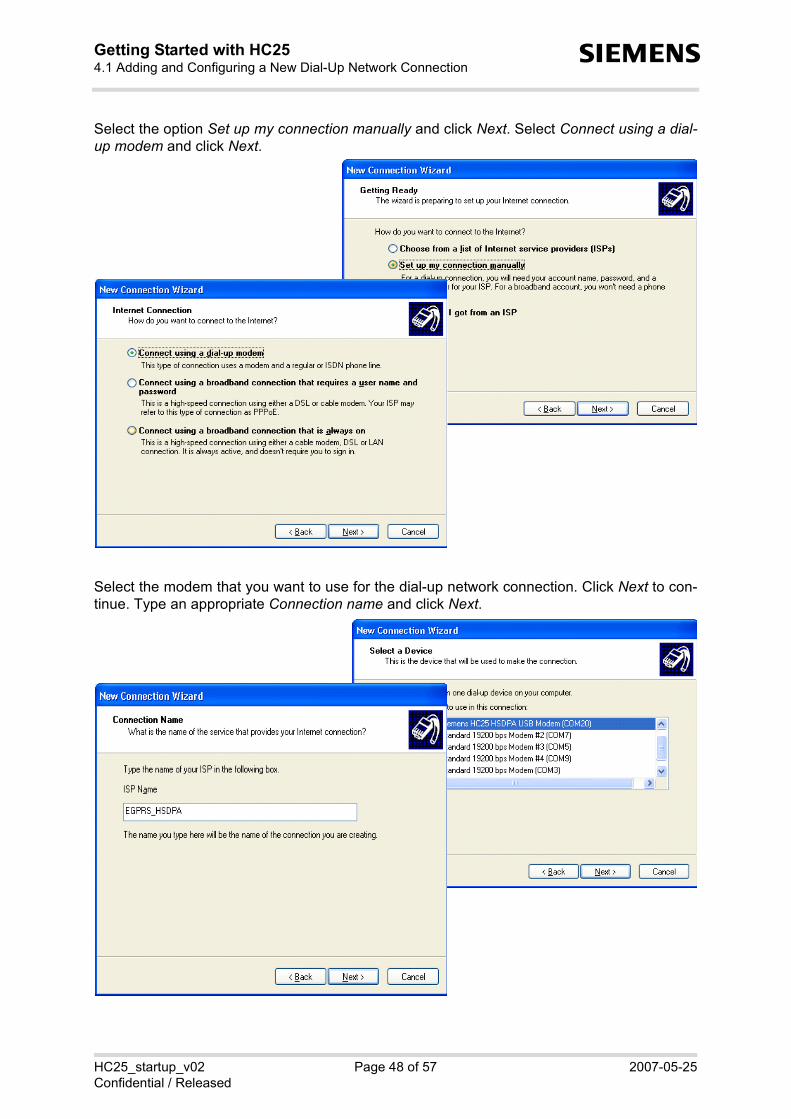
Select the option Set up my connection manually and click Next. Select Connect using a dial-up modem and click Next.
Select the modem that you want to use for the dial-up network connection. Click Next to con-tinue. Type an appropriate Connection name and click Next.

HC25_startup_v02 Page 49 of 57 2007-05-25Confidential / Released
Getting Started with HC254.1 Adding and Configuring a New Dial-Up Network Connection52
s
In the Phone number box, put thedial string *99***1# commonlyused to access the GPRS network. Note: The number "1" addedbefore the hash determines thatthe first PDP context shall be used.The number must be identical tothe <cid> value set with AT+CGD-CONT (see Section 3.7).
Depending on the network, youmay be required to put a Username and a Password for the dial-up network connection. If notrequired, you may leave all boxesempty. Click Next and, in theresulting dialog, click Finish.
This will cause the Connect… dia-log to appear (screen is shown inSection 4.1.2). Yet, at thismoment, it is recommended thatyou press Cancel in order tocheck, and if necessary, to config-ure the dial-up network connectionas described in Section 4.1.2.

HC25_startup_v02 Page 50 of 57 2007-05-25Confidential / Released
Getting Started with HC254.1 Adding and Configuring a New Dial-Up Network Connection52
s
4.1.2 Configuring a Dial-up Network Connection
Every newly created dial-up network connection should be configured before using it to estab-lish a PPP connection.
Open the Control Panel, double-click Network Connections, select the dial-up network connec-tion you want to configure. In the resulting Connect… dialog, press the Properties button.
On the General tab, select the modem you want to configure. The correct dial string *99***1#should already be given, if entered before in the Phone number box when the dial-up networkconnection was created (see Section 4.1.1).

HC25_startup_v02 Page 51 of 57 2007-05-25Confidential / Released
Getting Started with HC254.1 Adding and Configuring a New Dial-Up Network Connection52
s
Select the Security tab to verify or edit authentication options for PPP connections.
By default, MS Windows XP enables theoption Typical with unsecured passwords forthe commonly used but unsafe PAP authenti-cation method. As this is the minimum level ofsecurity supported in all networks the settingusually enables the subscriber to make a con-nection, though at the expense of security.
Many network operators apply more secure authentication methods for PPP connections, suchas CHAP. For access to these networks, activate the Advanced (custom setting) option andpress the Settings button. On the resulting Advanced Security Settings property page, enable/ disable the authentication protocols according to the information provisioned by your serviceprovider.
Note: If an attempt to connect to a HSDPA or GPRS network fails, check that the authenticationprotocols are properly set.

HC25_startup_v02 Page 52 of 57 2007-05-25Confidential / Released
Getting Started with HC254.1 Adding and Configuring a New Dial-Up Network Connection52
s
On the Networking tab, the default settings are acceptable in most cases: The drop-down menushows PPP: Windows 95/98/NT/2000, Internet for the type of dialup server as default.
Select the Internet Protocol (TCP/IP) on the Networking tab and press the Properties button togo to the General page. In most cases, it is sufficient to accept the default settings: Obtain anIP address automatically and Obtain DNS server address automatically.Otherwise, you have to select the options Use the following IP address / Use the following DNSaddresses and specify the IP addresses provisioned by your network operator. The Advanced button opens a further property page where you can set your preferences whenworking in a local network and a dial-up network at the same time.
In the PPP settings box, verify that EnableLCP extensions and Enable software com-pression are selected and click OK.

HC25_startup_v02 Page 53 of 57 2007-05-25Confidential / Released
Getting Started with HC255 Appendix II56
s
5 Appendix II
5.1 Configuring DSB75 Support Board and Adapter Board
This section refers to the DSB75 Support Board and the adapter board needed to mount aHC25 module onto the DSB75 Support Board.
The focus is on the configuration of several switches you may be required to change for usewith HC25. A detailed description of the DSB75 Support Board is given in [12].
Please check that all slide switches (S100 - S103) on your adapter board are set as shown inFigure 5.
Figure 5: Adapter board - switch settings
80-pin header
X108: Not poplu-lated
X106, X107: Not populated
X104: 50-pin board-to-board connector for HC25

Getting Started with HC255.1 Configuring DSB75 Support Board and Adapter Board
s
HC25_startup_v02 Page 54 of 57 2007-05-25Confidential / Released
Figure 6: Mounting HC25 to DSB75 (exploded view )

Getting Started with HC255.1 Configuring DSB75 Support Board and Adapter Board
s
HC25_startup_v02 Page 55 of 57 2007-05-25Confidential / Released
Figure 7: DSB75 Support Board - switches, connectors, LEDs (overview)
S300
S302
S304
S306
S301
S303
S305
S307
S712
S716
S717
S713
S731
S730S5
54S2
00S2
01
X561
X560
X500
S714
S715
S710
S711
X710
S5 01
S5 00 S 502
S 503
S 504
S 552
S 551
X410
S110
S111
S11
2
X120
S457 S456 S455
S452 S453 S454
S451 S450
S462 S461 S460
S463 S464 S465
S466 S467 S468
S469 S459 S458
X203
X400 = power supply connector (red) for 9V - 15VX401 =GND (black)
X110 = USB connector
X201, X202, X205:Do not use
X101, X102 = 80-pin header for adapter board
V430 = yellow LED (HC25 on)
V431 = green LED (DSB75 on)
X505 = Hirose U.FLX506 = SMA connector
X100: Do not use
X503 = SIM card holder
X502 = Audio western jack
X420 = EMERG_OFFX421 = IGT

Getting Started with HC255.1 Configuring DSB75 Support Board and Adapter Board
s
HC25_startup_v02 Page 56 of 57 2007-05-25Confidential / Released
Figure 8: Adapter board schematic
2-E8
2-F6
2-E8
CCGND_D
2-F6
2-F5,2-F7
2-C9
R105
0R
2-C4 2-B7,2-G5
2-B4 2-B7,2-F5
2-B4 2-B7,2-F5
2-B3
2-B11
2-D2
2-B4 2-B7,2-G5
2-B11
2-B3
2-B11
12
VMIC
2-E2
2-G9
2-E2
2-F9
2-B11
2-B4
S1033
2-G6
2-C7
2-D8
2-E2
2-G5,2-G7
2-E8
2-E8
2-E9
2-E8
100NC108
2-D4
2-G5,2-G7
C107100N
2-F5,2-F7
2-C2
S10231
2
VSIM_D
TP_RES $VVDDLP
0R
R103
50
6
7
8
9
C1041N
40
41
42
43
44
45
46
47
48
49
5
31
32
33
34
35
36
37
38
39
4
21
22
23
24
2526
27
28
29
3
30
11
12
13
14
15
16
17
18
19
2
20
2-D2
VAL
X10450-POL
SMD
$V,$P
1
10
2-C9
2-C10
2-C7
$V,$P
S101 31
2
C109100N
VSIM_D
GND
2-G6
VMIC
$V,$P
S100 31
2
GND
GND
VUSB_IN
1NC103
2-C4
0R
R104CCGND_D
AGND
38
39
4
40
5
6
7
8
9
28
29
3
30
31
32
33
34
35
36
37
18
19
2
20
21
22
23
24
25
26
27
$O,$V
1
10
11
12
13
14
15
16
17
VAL
X101
2-D4
2-C7
2-E9
2-C2
2-C10
2-C4
2-C7
2-E4
R102
0R
2-C10
2-G8
AGND
R100
0R
R101
0R
2-D2
2-C9
7
8
9
2-C7
2-D4
34
35
36
37
38
39
4
40
5
6
24
25
26
27
28
29
3
30
31
32
33
14
15
16
17
18
19
2
20
21
22
23
VAL
X100
$O,$V
1
10
11
12
13
VSIM
X1051
2
VUSB_IN
GND
VEXT
VDDLP
CCGND
GND
GND
2-D4
2-C9
2-E9
VSIM
CCGND
BATT+
BATT+
2-F8
2-G8
2-F8
2-C9
VEXT
2-D2
C1061N
2-E9
TP_USB_ID $V
1NC105
SDCC_D1
SDCC_D3
EPN
EPP
MICN
MICP
GPIO8
APP_CTRL3
APP_CTRL2
RXD0
TXD0
APP_CTRL0
EMERG_RST
IGT
MICP2CCIO_D
CCRST_D
CCIN_D
SDCC_CLK
SDCC_D0
SDCC_D2
CTS0
RTS0
GPIO7
MICN1
MICP1
MICN
SDCC_CMD
USB_DN
ISENSE
VSENSE
USC6
CCCLK_D
MICN2
CCCLK
CCIO
CCRST
CCIN
GP_CLK
PWR_IND
SD_CLK
SD_CMD
USB_DP
USB_DN
CCCLK
CCIO
CCRST
CCIN
CCCLK_D
EPN
EPP
CCIO_D
CCRST_D
AD1_IN
DAC_OUT
AD2_IN
PWR_IND
TP_ENV
TXD2_GPIO10
RXD2_GPIO9
SD_WP
GPIO7
GPIO8
SD_D3
SD_DET
SD_D2
SD_CMD
SD_D1
SD_CLK
SD_D0
I2CCLK
CCIN_D
I2CDAT
USB_DP
USC5
APP_CTRL1
MICP
MICN2
MICP2
USC4
MICP1
USC3
MICN1
USC2
USC1
IGT
USC0
EMERG_RST
BATTEMP
DCD0
SYNC
CTS1
RXD1
CTS0
RXD0
RTS1
TXD1
DTR0
TXD0
RTS0
DSR0
VCHARGE
RING0
CHARGEGATE

Getting Started with HC256 Index57
HC25_startup_v02 Page 57 of 57 2007-05-25Confidential / Released
s
6 Index
AAdapter board for DSB75 .. 10, 11, 54, 56Antenna .................................................. 10
Hirose U.FL ................................. 8, 10SMA .................................................. 10
APN ..................................... 9, 39, 41, 44Application interface ........................ 23, 36AT Command Interpreter ........................ 36ATD ........................................................ 40ATE ........................................................ 46AT+CGATT ............................................ 39AT+CGDCONT ...................................... 39AT+CHUP .............................................. 40AT+COPS .............................................. 38AT+CPIN ................................................ 37AT^SMSO .............................................. 37AT^SQPORT .......................................... 36
CCustomizing device names .................... 34
DDial-up network connection
Configuring ....................................... 47Using ................................................ 41
DSB75 Support Board 10, 11, 53, 54, 55
HHSDPA/GPRS data transfer
Dial-up network connection 41, 45, 46Siemens Connection Manager . 41, 43, 44
IInstallation
Hardware .......................................... 10Update ................................ 30, 31, 32Windows Vista ........................... 17, 20Windows XP .............................. 12, 14
LLocal echo ....................................... 36, 46
MMass storage ................ 9, 12, 17, 21, 32Modem interface .............................. 22, 36Mounting
Exploded view .................................. 54Instructions ....................................... 10
PPDP context ............................. 22, 39, 45
RRemovable disk ................. 12, 17, 21, 32RF antenna connector ....................... 8, 10
SSelecting access technology .................. 38Siemens Connection Manager . 13, 41– 44Siemens HSDPA USB Modem 14, 22, 36,
........................................................... 41Siemens USB Com Port ........... 14, 22, 36Siemens Wireless Ethernet Adapter 14, 23,
.......................................................... 41SMARTEQ MiniMag antenna ................... 8
TTechnical requirements ............................ 8
UUICC .................................................. 8, 36Uninstalling ...................................... 24– 29Unsolicited Result Code Presentation .... 36Updating driver package ................. 30– 33URC ........................................................ 36
WWindows Device Manager ........ 22, 23, 29