Embed Size (px)
Citation preview
USER’S GUIDEInstallation & Operation
Instructions
Pump Station Level Controller
Model PSL
Manual Series B.11.2
www.greyline.com

Note: This page has been left blank intentionally.
IMPORTANT NOTE: This instrument is manufactured and calibrated to meet product specifications.Please read this manual carefully before installation and operation. Any unauthorized repairs ormodifications may result in a suspension of the warranty.
Available in Adobe Acrobat pdf format
Page 3
PSL Pump Station Level Controller
Manual Series B.11.2
INDEX
Bench Test · · · · · · · · · · · · · · · · · · · · · · · · · · · · · · · 4Connections · · · · · · · · · · · · · · · · · · · · · · · · · · · · · · · 4RS-232C Serial Output · · · · · · · · · · · · · · · · · · · · · · · · · · 5Keypad System · · · · · · · · · · · · · · · · · · · · · · · · · · · · · 6Menu - Flow Chart · · · · · · · · · · · · · · · · · · · · · · · · · · · · 6Display Units · · · · · · · · · · · · · · · · · · · · · · · · · · · · · · 8Echo Confidence· · · · · · · · · · · · · · · · · · · · · · · · · · · · · 8Relay Status · · · · · · · · · · · · · · · · · · · · · · · · · · · · · · · 8Password · · · · · · · · · · · · · · · · · · · · · · · · · · · · · · · · 9Units / Mode· · · · · · · · · · · · · · · · · · · · · · · · · · · · · · · 9Calibration- for Level Control · · · · · · · · · · · · · · · · · · · · · · 104/20mA Current Loop Offset · · · · · · · · · · · · · · · · · · · · · · · 11Damping · · · · · · · · · · · · · · · · · · · · · · · · · · · · · · · · 11Rejection Time · · · · · · · · · · · · · · · · · · · · · · · · · · · · · 11Relay Parameters · · · · · · · · · · · · · · · · · · · · · · · · · · · · 12Special Functions · · · · · · · · · · · · · · · · · · · · · · · · · · · · 14Sensor Mounting Location · · · · · · · · · · · · · · · · · · · · · · · · 17Enclosure Installation · · · · · · · · · · · · · · · · · · · · · · · · · · 19Error/Warning Messages · · · · · · · · · · · · · · · · · · · · · · · · · 20Troubleshooting · · · · · · · · · · · · · · · · · · · · · · · · · · · · · 21Installation Considerations in Noisy Environments· · · · · · · · · · · · · 25Applications Hotline · · · · · · · · · · · · · · · · · · · · · · · · · · · 27Product Return Procedure · · · · · · · · · · · · · · · · · · · · · · · · 28Warranty · · · · · · · · · · · · · · · · · · · · · · · · · · · · · · · · 29Appendix A - Options · · · · · · · · · · · · · · · · · · · · · · · · · · 30Appendix B - Applications Background · · · · · · · · · · · · · · · · · · 36Conversion Guide · · · · · · · · · · · · · · · · · · · · · · · · · · · · 37Specifications · · · · · · · · · · · · · · · · · · · · · · · · · · · · · · 38
QUICK BENCH TEST:
Connect Sensor as shown below, then apply Power. When properly connected a soft clicking can beheard from the sensor and figures will show on the large LCD display. Test operation of the PSL byholding the sensor steadily and aiming at a flat, stable target 16 to 30" (50 to 100 cm) away from the end of the sensor. Allow a few seconds for the PSL to lock onto the target before displaying its distance. The PSL will now display distance in ft or cm (factory calibration).
Note: The PSL will not detect targets beyond user entered MaxRg.
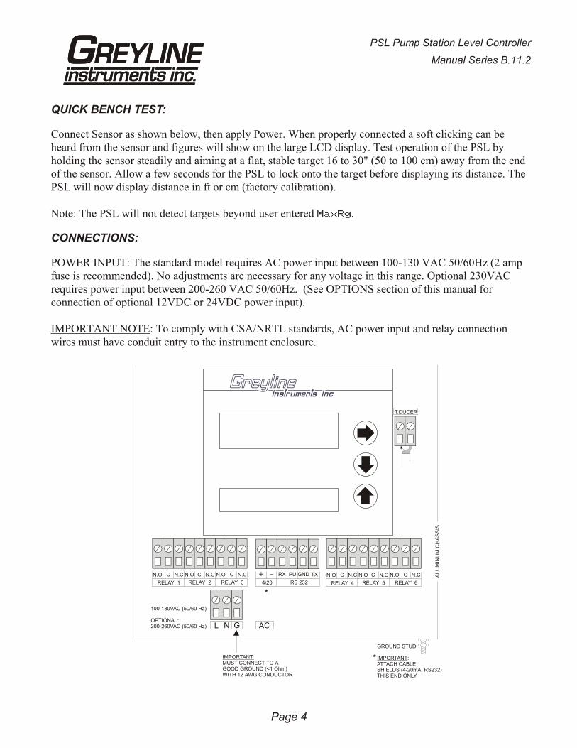
CONNECTIONS:
POWER INPUT: The standard model requires AC power input between 100-130 VAC 50/60Hz (2 ampfuse is recommended). No adjustments are necessary for any voltage in this range. Optional 230VACrequires power input between 200-260 VAC 50/60Hz. (See OPTIONS section of this manual forconnection of optional 12VDC or 24VDC power input).
IMPORTANT NOTE: To comply with CSA/NRTL standards, AC power input and relay connectionwires must have conduit entry to the instrument enclosure.
Page 4
PSL Pump Station Level Controller
Manual Series B.11.2
T.DUCER
N.O C N.C N.O C N.C N.O C N.C
RELAY 1 RELAY 2 RELAY 3
L N G AC
RX PU GND TX
RS 232
N.O C N.C N.O C N.C N.O C N.C
RELAY 4 RELAY 5 RELAY 64\20
GROUND STUD
IMPORTANT:ATTACH CABLESHIELDS (4-20mA, RS232)THIS END ONLY
IMPORTANT:MUST CONNECT TO AGOOD GROUND (<1 Ohm)WITH 12 AWG CONDUCTOR
100-130VAC (50/60 Hz)
OPTIONAL:200-260VAC (50/60 Hz)
*
*
ALU
MIN
UM
CH
AS
SIS
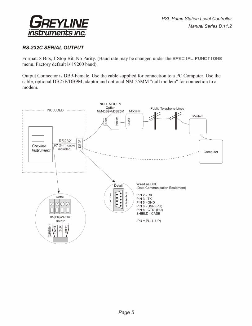
RS-232C SERIAL OUTPUT
Format: 8 Bits, 1 Stop Bit, No Parity. (Baud rate may be changed under the SPECIAL FUNCTIONS
menu. Factory default is 19200 baud).
Output Connector is DB9-Female. Use the cable supplied for connection to a PC Computer. Use thecable, optional DB25F/DB9M adaptor and optional NM-25MM "null modem" for connection to amodem.
Page 5
PSL Pump Station Level Controller
Manual Series B.11.2
GreylineInstrument
RS23220' (6 m) cable
included
Detail
INCLUDED
RX
RS 232
PU GND TX
(GR
EE
N)
(WH
T)
(BL
K)
(RE
D)
Wired as DCE(Data Communication Equipment)
PIN 2 - RXPIN 3 - TXPIN 5 - GND
SHIELD - CASE
(PU = PULL-UP)
PIN 6 - DSR (PU)PIN 8 - CTS (PU)
54321
9876
Detail
DB
9F
DB
25F
Modem
Modem
Computer
DB
9M
DB
25M
Public Telephone Lines
NULL MODEMOption
NM-DB9M/DB25M
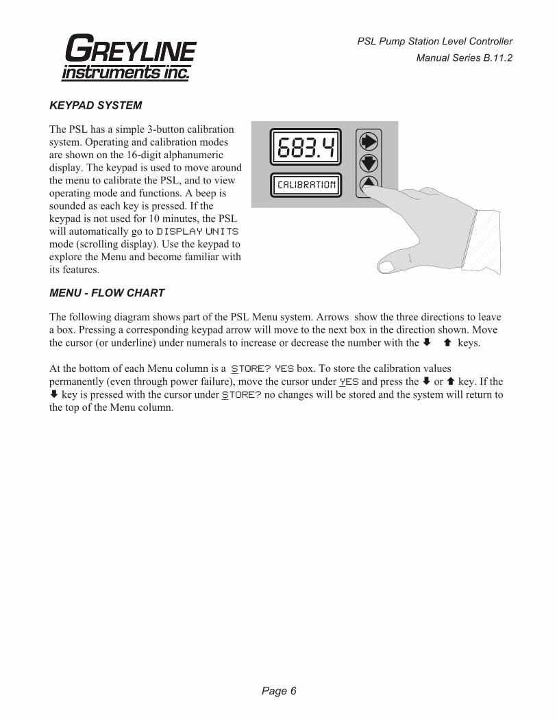
KEYPAD SYSTEM
The PSL has a simple 3-button calibrationsystem. Operating and calibration modesare shown on the 16-digit alphanumericdisplay. The keypad is used to move around the menu to calibrate the PSL, and to viewoperating mode and functions. A beep issounded as each key is pressed. If thekeypad is not used for 10 minutes, the PSLwill automatically go to DISPLAY UNITS
mode (scrolling display). Use the keypad toexplore the Menu and become familiar with its features.
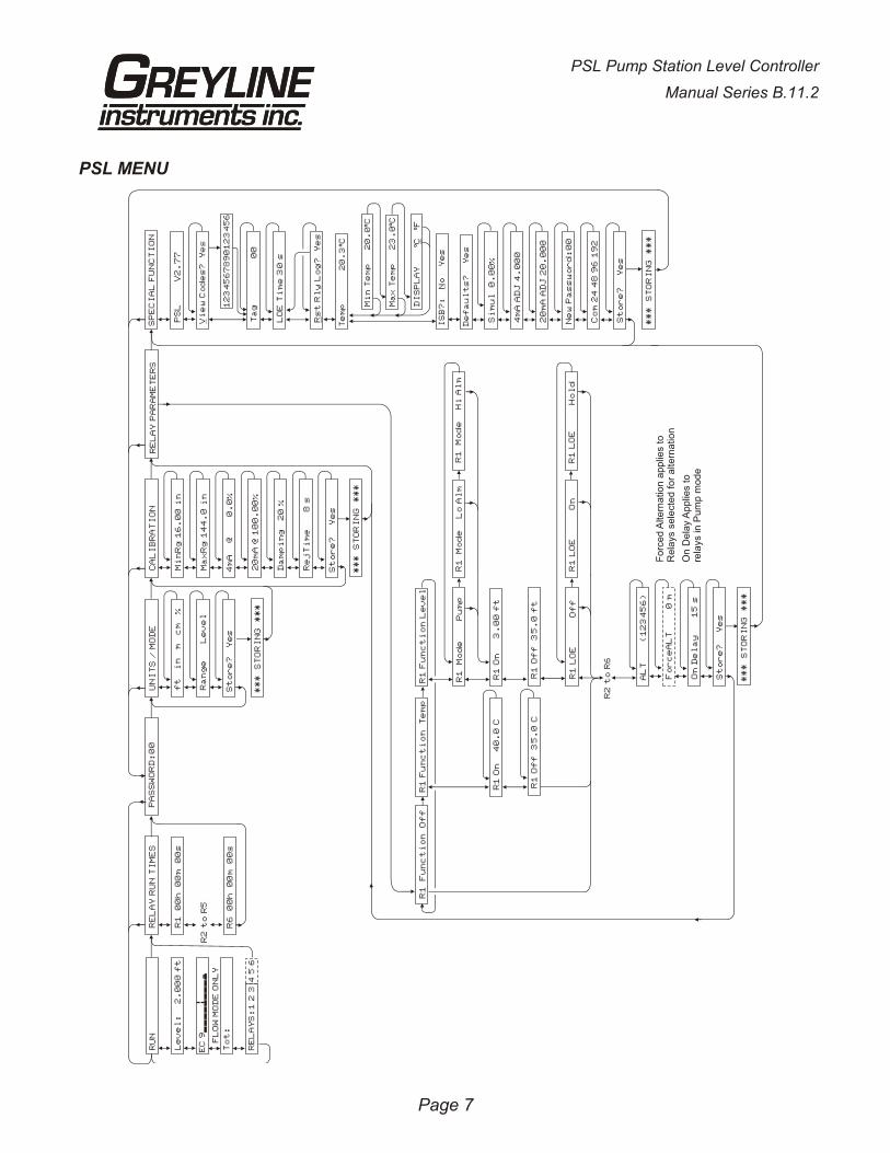
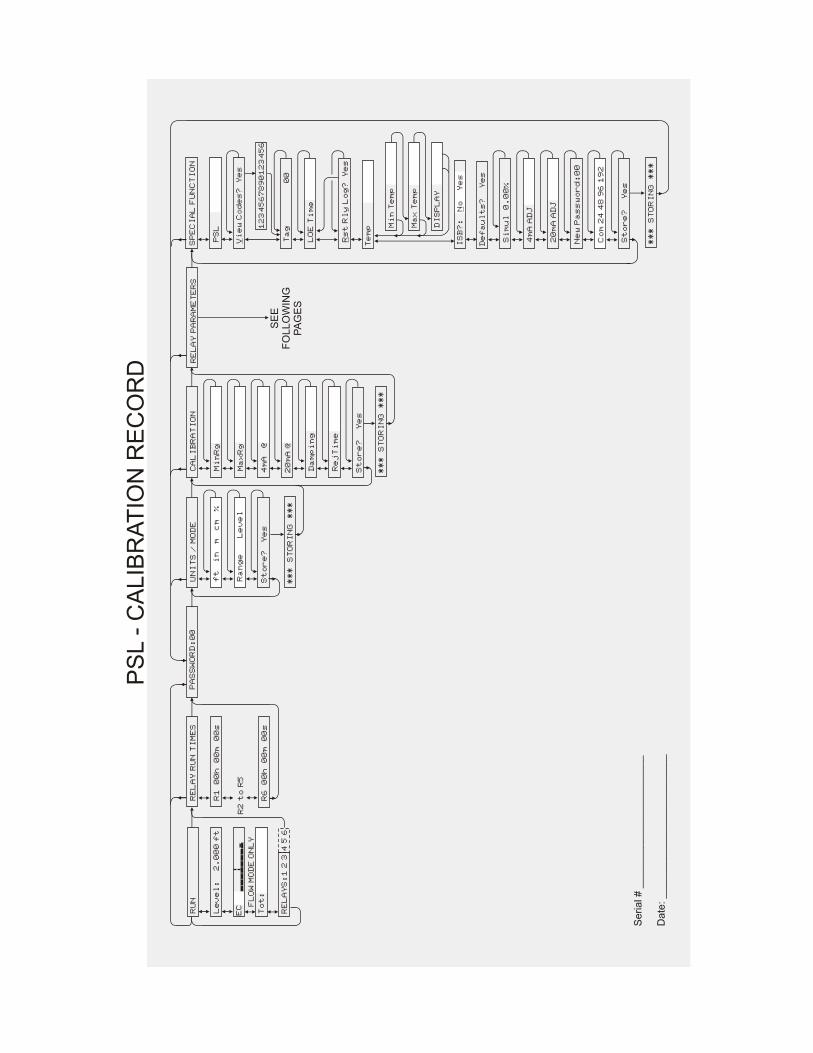
MENU - FLOW CHART
The following diagram shows part of the PSL Menu system. Arrows show the three directions to leavea box. Pressing a corresponding keypad arrow will move to the next box in the direction shown. Movethe cursor (or underline) under numerals to increase or decrease the number with the È Ç keys.
At the bottom of each Menu column is a STORE? YES box. To store the calibration valuespermanently (even through power failure), move the cursor under YES and press the È or Ç key. If the È key is pressed with the cursor under STORE? no changes will be stored and the system will return tothe top of the Menu column.
Page 6
PSL Pump Station Level Controller
Manual Series B.11.2
PSL MENU
Page 7
PSL Pump Station Level Controller
Manual Series B.11.2
UN
IT
S /
MO
DE
Ra
ng
e
L
ev
el
ft
i
n
m c
m
%
St
or
e?
Y
es
CA
LI
BR
AT
IO
N
Mi
nR
g 1
6.
00
in
Ma
xR
g 1
44
.0
in
4m
A @
0
.0
%
20
mA
@ 1
00
.0
0%
Da
mp
in
g 2
0 %
Re
jT
im
e 8
s
St
or
e?
Y
es
RE
LA
Y R
UN
TI
ME
S
R1
0
0h
0
0m
0
0s
R6
0
0h
0
0m
0
0s
PA
SS
WO
RD
:0
0S
PE
CI
AL
FU
NC
TI
ON
PS
L
V
2.
77
RE
LA
Y P
AR
AM
ET
ER
S
R2
to
R5
**
*
ST
OR
IN
G
**
*
**
*
ST
OR
IN
G
**
*
R1
Of
f 3
5.
0°C
R1
Of
f 3
5.
0 f
t
R1
LO
E
H
ol
dR
1 L
OE
O
ff
R1
LO
E
O
n
R2
to
R6
AL
T
(1
23
45
6)
Fo
rc
eA
LT
0 m
On
De
la
y
1
5 s
St
or
e?
Y
es
R1
F
un
ct
io
n O
ff
R1
Fu
nc
ti
on
T
em
pR
1 F
un
ct
io
n L
ev
el
R1
M
od
e
P
um
pR
1
Mo
de
Lo
Al
mR
1
Mo
de
Hi
Al
m
R1
On
40
.0
°CR
1 O
n
3.
00
ft
Fo
rce
d A
lte
rna
tio
n a
pp
lies t
oR
ela
ys s
ele
cte
d f
or
alte
rna
tio
n
On
De
lay A
pp
lies t
ore
lays in
Pu
mp
mo
de
**
*
ST
OR
IN
G
**
*
Vi
ew
Co
de
s?
Y
es
Ta
g
0
0
LO
E T
im
e 3
0 s
Rs
t R
ly
Lo
g?
Y
es
Si
mu
l 0
.0
0%
4m
A A
DJ
4.
00
0
20
mA
AD
J 2
0.
00
0
Ne
w P
as
sw
or
d:
00
Co
m 2
4 4
8 9
6 1
92
St
or
e?
Y
es
**
*
ST
OR
IN
G
**
*
12
34
56
78
90
12
34
56
Te
mp
2
0.
3Cº
Mi
n T
em
p
2
0.
0Cº
Ma
x T
em
p
2
3.
0Cº
DI
SP
LA
Y
C
F
ºº
IS
B?
: N
o Y
es
De
fa
ul
ts
?
Ye
s
RU
N
Le
ve
l:
2.
00
0 f
t
FL
OW
MO
DE
ON
LY
RE
LA
YS
:1
2 3
4 5
6
To
t:
EC
9
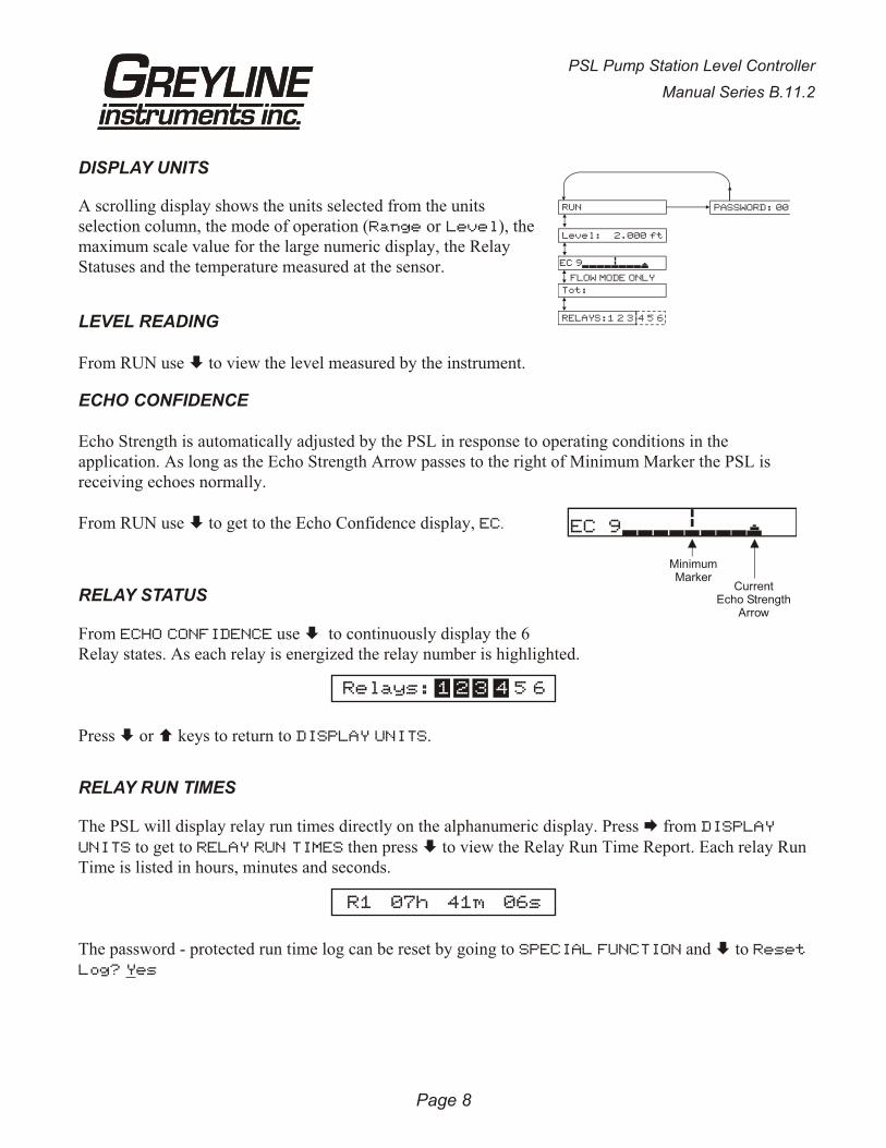
DISPLAY UNITS
A scrolling display shows the units selected from the unitsselection column, the mode of operation (Range or Level), themaximum scale value for the large numeric display, the RelayStatuses and the temperature measured at the sensor.
LEVEL READING
From RUN use È to view the level measured by the instrument.
ECHO CONFIDENCE
Echo Strength is automatically adjusted by the PSL in response to operating conditions in theapplication. As long as the Echo Strength Arrow passes to the right of Minimum Marker the PSL isreceiving echoes normally.
From RUN use È to get to the Echo Confidence display, EC.
RELAY STATUS
From ECHO CONFIDENCE use È to continuously display the 6Relay states. As each relay is energized the relay number is highlighted.
Press È or Ç keys to return to DISPLAY UNITS.
RELAY RUN TIMES
The PSL will display relay run times directly on the alphanumeric display. Press Æ from DISPLAY
UNITS to get to RELAY RUN TIMES then press È to view the Relay Run Time Report. Each relay Run Time is listed in hours, minutes and seconds.
The password - protected run time log can be reset by going to SPECIAL FUNCTION and È to Reset
Log? Yes
Page 8
PSL Pump Station Level Controller
Manual Series B.11.2
Relays: 5 61 2 3 41
R1 07h 41m 06s
PASSWORD: 00RUN
Level: 2.000 ft
FLOW MODE ONLY
RELAYS:1 2 3 4 5 6
Tot:
EC 9
CurrentEcho Strength
Arrow
MinimumMarker
EC 9

PASSWORD
The password (a number from 00 to 99) prevents unauthorized access to theCALIBRATION MODE.
From DISPLAY UNITS press Æ past RELAY RUN TIMES to get toPASSWORD.
Press Æ to place the cursor under the digits and È or Ç to change the number.
Factory default Password is 00. A new password can be stored by going Æ to SPECIAL FUNCTIONS
and È to New Password.
UNITS / MODE
Press Æ to UNITS/MODE, then È to Range Level. Use Æ to select the operating mode of the PSL.
Range this mode displays distance from the sensor to the target or liquid surface like a tape measure.Range mode is useful to measure the exact distance from the sensor to the zero level duringcalibration, or to monitor “outage” or free space in a tank.
Level this is the most common mode and it is used to measure pump station level or tank inventory
Press È from Range or Level mode to
Press Æ to move the cursor under the required measurement units:ft - feetin - inchesm - meterscm - centimeters% - percent
Press È to Store and Æ to Yes. Then press È or Ç to store your UNITS/MODE selections.
Page 9
PSL Pump Station Level Controller
Manual Series B.11.2
ft in m cm %
PASSWORD: 00
PASSWORD: 00
PASSWORD: 10
UNITS / MODE
Range Level
ft in m cm %
Store? Yes
CALIBRATIONPASSWORD:00
*** STORING ***
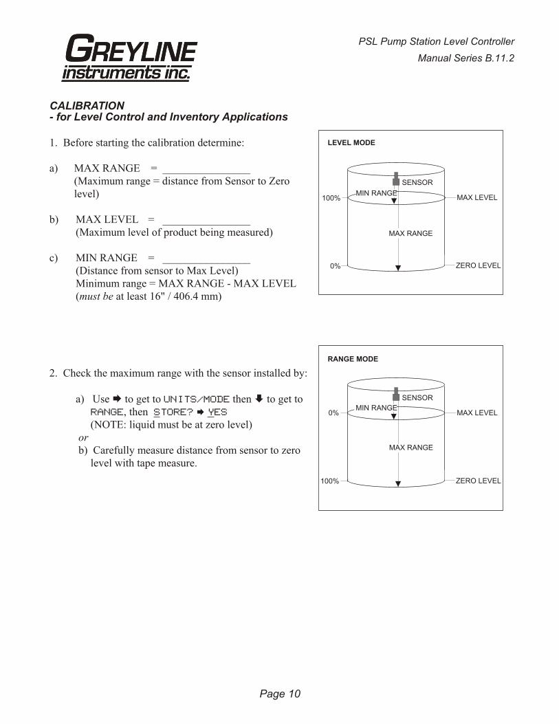
CALIBRATION- for Level Control and Inventory Applications
1. Before starting the calibration determine:
a) MAX RANGE = ________________(Maximum range = distance from Sensor to Zerolevel)
b) MAX LEVEL = ________________(Maximum level of product being measured)
c) MIN RANGE = ________________(Distance from sensor to Max Level)Minimum range = MAX RANGE - MAX LEVEL(must be at least 16" / 406.4 mm)
2. Check the maximum range with the sensor installed by:
a) Use Æ to get to UNITS/MODE then È to get to RANGE, then STORE? Æ YES
(NOTE: liquid must be at zero level) or b) Carefully measure distance from sensor to zero
level with tape measure.
Page 10
PSL Pump Station Level Controller
Manual Series B.11.2
MAX LEVEL
ZERO LEVEL
MAX RANGE
MIN RANGE
LEVEL MODE
SENSOR
100%
0%
MAX LEVEL
ZERO LEVEL
MIN RANGE
RANGE MODE
SENSOR
0%
100%
MAX RANGE
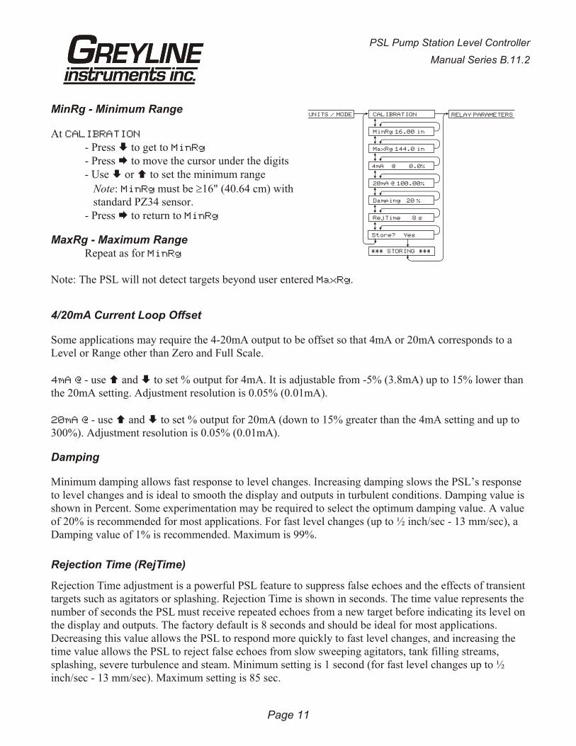
MinRg - Minimum Range
At CALIBRATION
- Press È to get to MinRg
- Press Æ to move the cursor under the digits- Use È or Ç to set the minimum range
Note: MinRg must be ³16" (40.64 cm) withstandard PZ34 sensor.
- Press Æ to return to MinRg
MaxRg - Maximum RangeRepeat as for MinRg
Note: The PSL will not detect targets beyond user entered MaxRg.
4/20mA Current Loop Offset
Some applications may require the 4-20mA output to be offset so that 4mA or 20mA corresponds to aLevel or Range other than Zero and Full Scale.
4mA @ - use Ç and È to set % output for 4mA. It is adjustable from -5% (3.8mA) up to 15% lower than the 20mA setting. Adjustment resolution is 0.05% (0.01mA).
20mA @ - use Ç and È to set % output for 20mA (down to 15% greater than the 4mA setting and up to300%). Adjustment resolution is 0.05% (0.01mA).
Damping
Minimum damping allows fast response to level changes. Increasing damping slows the PSL’s responseto level changes and is ideal to smooth the display and outputs in turbulent conditions. Damping value is shown in Percent. Some experimentation may be required to select the optimum damping value. A value of 20% is recommended for most applications. For fast level changes (up to ½ inch/sec - 13 mm/sec), aDamping value of 1% is recommended. Maximum is 99%.
Rejection Time (RejTime)
Rejection Time adjustment is a powerful PSL feature to suppress false echoes and the effects of transient targets such as agitators or splashing. Rejection Time is shown in seconds. The time value represents the number of seconds the PSL must receive repeated echoes from a new target before indicating its level on the display and outputs. The factory default is 8 seconds and should be ideal for most applications.Decreasing this value allows the PSL to respond more quickly to fast level changes, and increasing thetime value allows the PSL to reject false echoes from slow sweeping agitators, tank filling streams,splashing, severe turbulence and steam. Minimum setting is 1 second (for fast level changes up to ½inch/sec - 13 mm/sec). Maximum setting is 85 sec.
Page 11
PSL Pump Station Level Controller
Manual Series B.11.2
UNITS / MODE CALIBRATION
MinRg 16.00 in
MaxRg 144.0 in
4mA @ 0.0%
20mA @ 100.00%
Damping 20 %
RejTime 8 s
Store? Yes
RELAY PARAMETERS
*** STORING ***
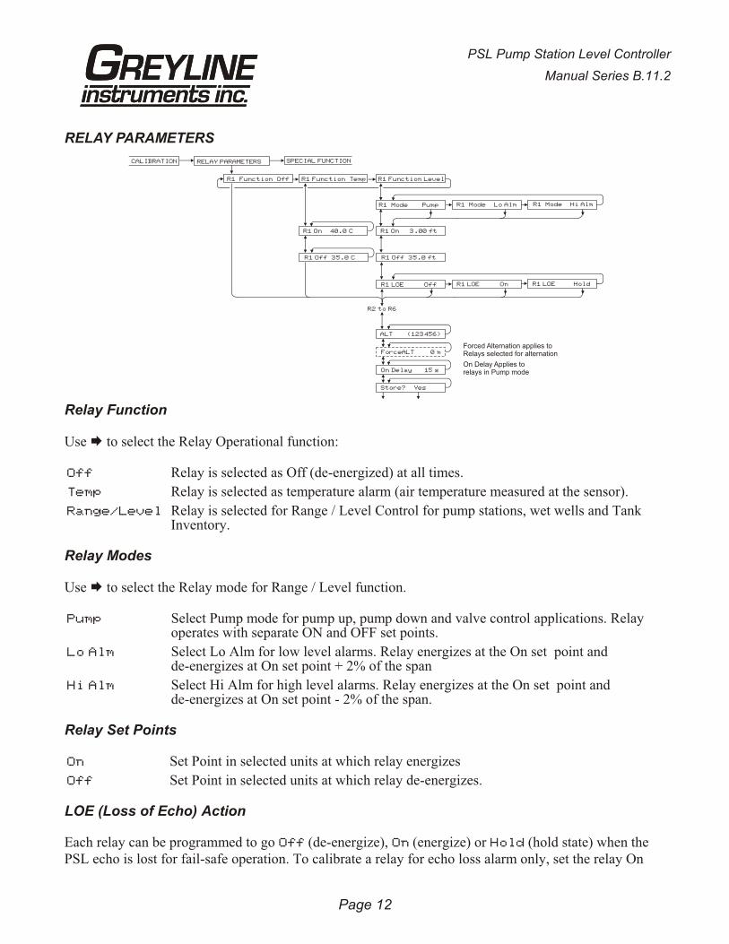
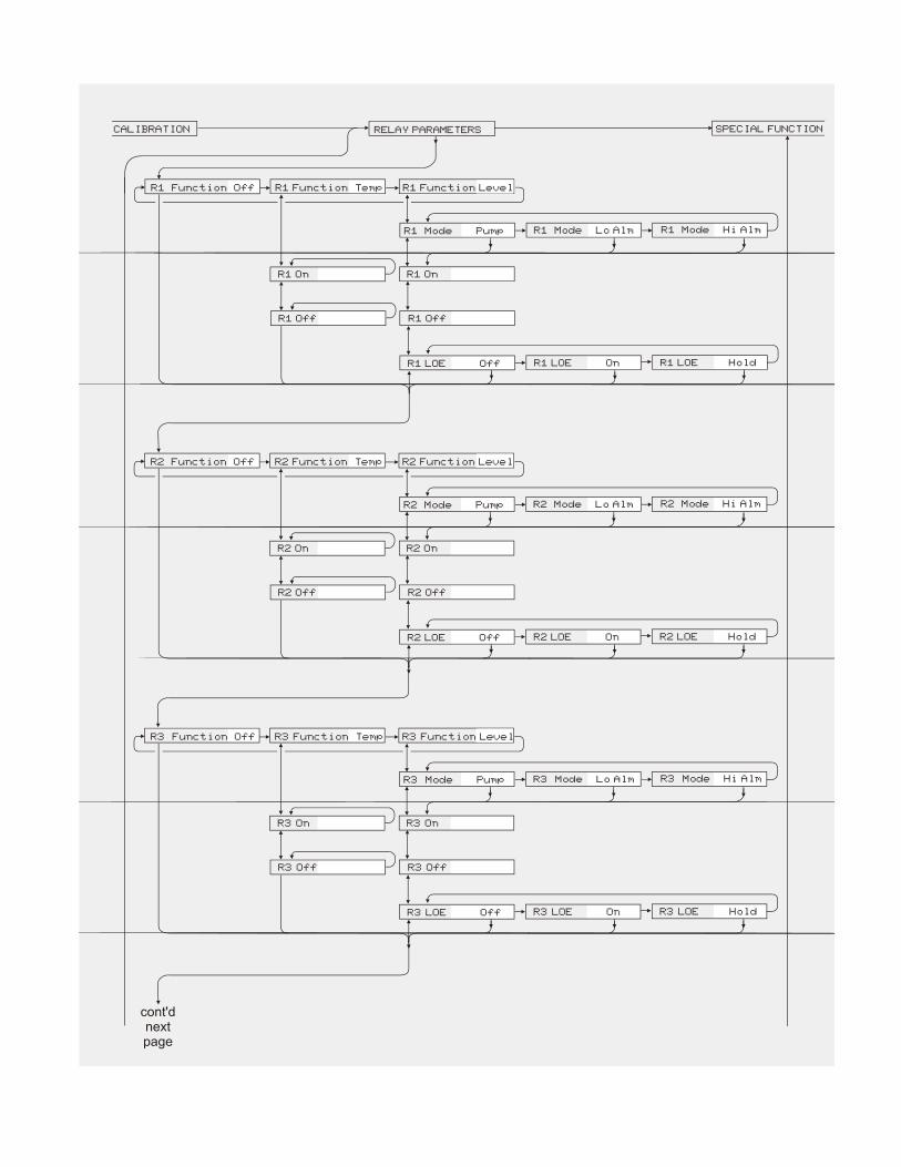
RELAY PARAMETERS
Relay Function
Use Æ to select the Relay Operational function:
Off Relay is selected as Off (de-energized) at all times.
Temp Relay is selected as temperature alarm (air temperature measured at the sensor).
Range/Level Relay is selected for Range / Level Control for pump stations, wet wells and TankInventory.
Relay Modes
Use Æ to select the Relay mode for Range / Level function.
Pump Select Pump mode for pump up, pump down and valve control applications. Relayoperates with separate ON and OFF set points.
Lo Alm Select Lo Alm for low level alarms. Relay energizes at the On set point andde-energizes at On set point + 2% of the span
Hi Alm Select Hi Alm for high level alarms. Relay energizes at the On set point andde-energizes at On set point - 2% of the span.
Relay Set Points
On Set Point in selected units at which relay energizes
Off Set Point in selected units at which relay de-energizes.
LOE (Loss of Echo) Action
Each relay can be programmed to go Off (de-energize), On (energize) or Hold (hold state) when thePSL echo is lost for fail-safe operation. To calibrate a relay for echo loss alarm only, set the relay On
Page 12
PSL Pump Station Level Controller
Manual Series B.11.2
R1 Off 35.0°C R1 Off 35.0 ft
R1 LOE HoldR1 LOE Off R1 LOE On
R2 to R6
ALT (123456)
ForceALT 0 m
On Delay 15 s
Store? Yes
R1 Function Off R1 Function Temp R1 Function Level
R1 Mode Pump R1 Mode Lo Alm R1 Mode Hi Alm
R1 On 40.0°C R1 On 3.00 ft
Forced Alternation applies toRelays selected for alternation
On Delay Applies torelays in Pump mode
CALIBRATION SPECIAL FUNCTIONRELAY PARAMETERS
and Off set points to exactly the same value, and then set LOE to On mode. The relay will now energizeonly when an echo loss condition occurs.
Use Æ to select the LOE action
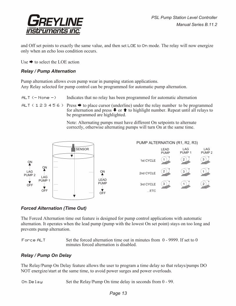
Relay / Pump Alternation
Pump alternation allows even pump wear in pumping station applications.Any Relay selected for pump control can be programmed for automatic pump alternation.
ALT (- None -) Indicates that no relay has been programmed for automatic alternation
ALT ( 1 2 3 4 5 6 ) Press Æ to place cursor (underline) under the relay number to be programmed for alternation and press È or Ç to highlight number. Repeat until all relays to be programmed are highlighted.
Note: Alternating pumps must have different On setpoints to alternatecorrectly, otherwise alternating pumps will turn On at the same time.
Forced Alternation (Time Out)
The Forced Alternation time out feature is designed for pump control applications with automaticalternation. It operates when the lead pump (pump with the lowest On set point) stays on too long andprevents pump alternation.
Force ALT Set the forced alternation time out in minutes from 0 - 9999. If set to 0minutes forced alternation is disabled.
Relay / Pump On Delay
The Relay/Pump On Delay feature allows the user to program a time delay so that relays/pumps DONOT energize/start at the same time, to avoid power surges and power overloads.
On Delay Set the Relay/Pump On time delay in seconds from 0 - 99.
PSL Pump Station Level Controller
Manual Series B.11.2
Page 13
SENSOR
LAGPUMP 1
LAGPUMP 2
LEADPUMP
ON
ON
OFF
OFF
ON
OFF
PUMP ALTERNATION (R1, R2, R3)
LEADPUMP
LAGPUMP 1
LAGPUMP 2
1st CYCLE
2nd CYCLE
3rd CYCLE
...ETC
1 2
2 3
3 1
3
1
2
SPECIAL FUNCTIONS
Page 14
PSL Pump Station Level Controller
Manual Series B.11.2
SPECIAL FUNCTION
PSL V2.77
View Codes? Yes
Tag 00
LOE Time 30 s
Rst Rly Log? Yes
Simul 0.00%
4mA ADJ 4.000
20mA ADJ 20.000
New Password:00
Com 24 48 96 192
Store? Yes
*** STORING ***
1234567890123456
Temp 20.3 Cº
Min Temp 20.0 Cº
Max Temp 23.0 Cº
DISPLAY C Fº º
ISB?: No Yes
Defaults? Yes
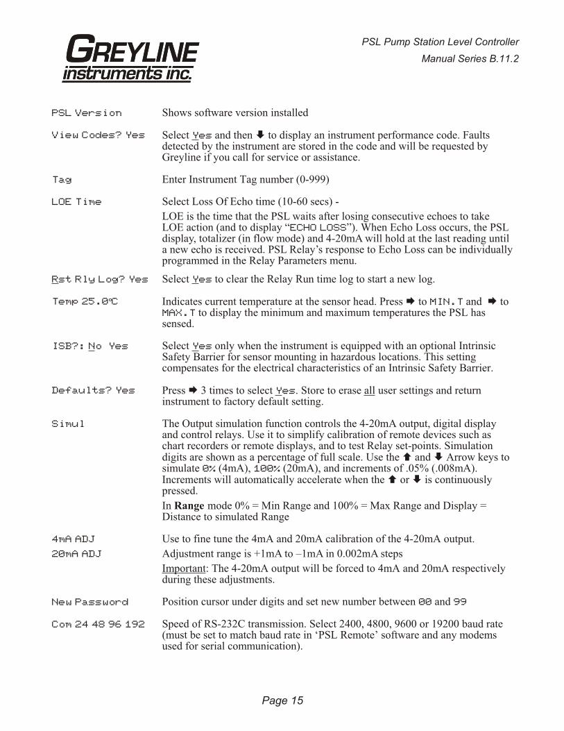
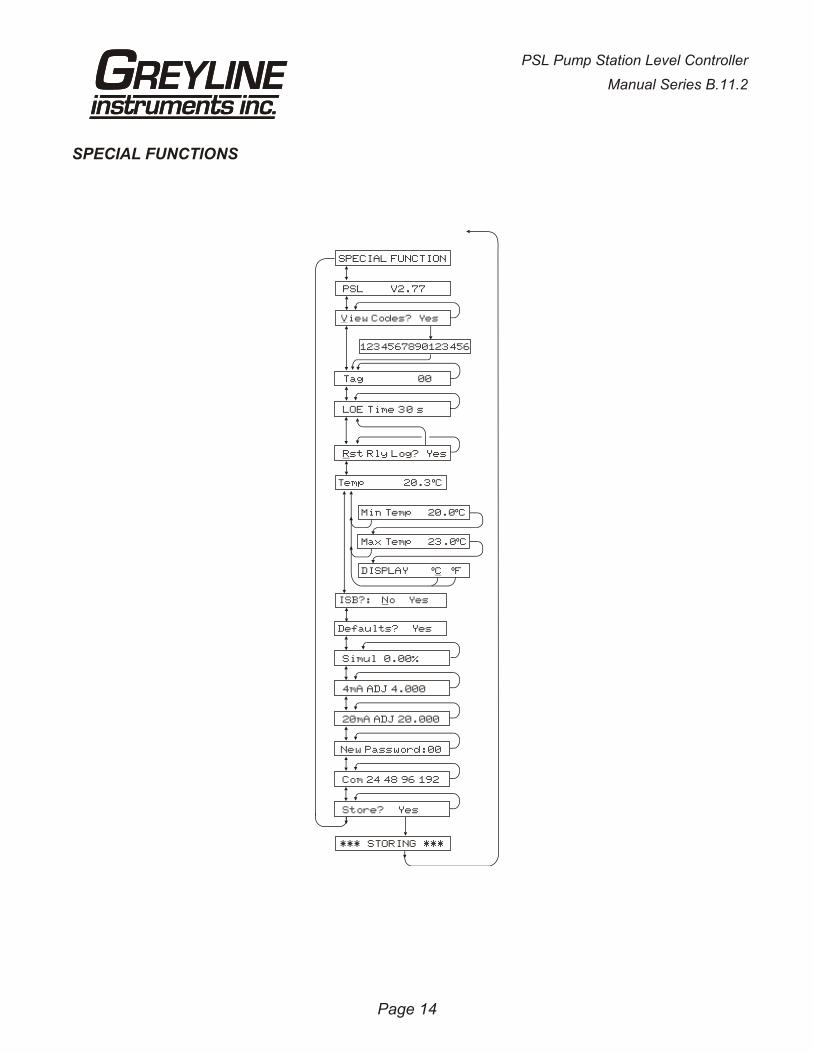
PSL Version Shows software version installed
View Codes? Yes Select Yes and then È to display an instrument performance code. Faultsdetected by the instrument are stored in the code and will be requested byGreyline if you call for service or assistance.
Tag Enter Instrument Tag number (0-999)
LOE Time Select Loss Of Echo time (10-60 secs) -
LOE is the time that the PSL waits after losing consecutive echoes to takeLOE action (and to display “ECHO LOSS”). When Echo Loss occurs, the PSLdisplay, totalizer (in flow mode) and 4-20mA will hold at the last reading untila new echo is received. PSL Relay’s response to Echo Loss can be individually programmed in the Relay Parameters menu.
Rst Rly Log? Yes Select Yes to clear the Relay Run time log to start a new log.
Temp 25.0°C Indicates current temperature at the sensor head. Press Æ to MIN.T and Æ to MAX.T to display the minimum and maximum temperatures the PSL hassensed.
ISB?: No Yes Select Yes only when the instrument is equipped with an optional IntrinsicSafety Barrier for sensor mounting in hazardous locations. This settingcompensates for the electrical characteristics of an Intrinsic Safety Barrier.
Defaults? Yes Press Æ 3 times to select Yes. Store to erase all user settings and returninstrument to factory default setting.
Simul The Output simulation function controls the 4-20mA output, digital displayand control relays. Use it to simplify calibration of remote devices such aschart recorders or remote displays, and to test Relay set-points. Simulationdigits are shown as a percentage of full scale. Use the Ç and È Arrow keys to simulate 0% (4mA), 100% (20mA), and increments of .05% (.008mA).Increments will automatically accelerate when the Ç or È is continuouslypressed.
In Range mode 0% = Min Range and 100% = Max Range and Display =Distance to simulated Range
4mA ADJ
20mA ADJ
Use to fine tune the 4mA and 20mA calibration of the 4-20mA output.
Adjustment range is +1mA to –1mA in 0.002mA steps
Important: The 4-20mA output will be forced to 4mA and 20mA respectivelyduring these adjustments.
New Password Position cursor under digits and set new number between 00 and 99
Com 24 48 96 192 Speed of RS-232C transmission. Select 2400, 4800, 9600 or 19200 baud rate(must be set to match baud rate in ‘PSL Remote’ software and any modemsused for serial communication).
PSL Pump Station Level Controller
Manual Series B.11.2
Page 15
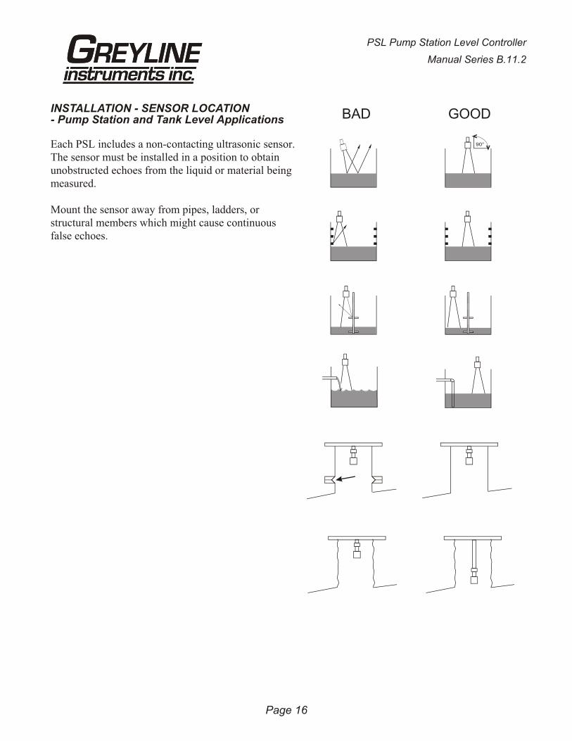
INSTALLATION - SENSOR LOCATION- Pump Station and Tank Level Applications
Each PSL includes a non-contacting ultrasonic sensor.The sensor must be installed in a position to obtainunobstructed echoes from the liquid or material beingmeasured.
Mount the sensor away from pipes, ladders, orstructural members which might cause continuousfalse echoes.
Page 16
PSL Pump Station Level Controller
Manual Series B.11.2
BAD GOOD
90°
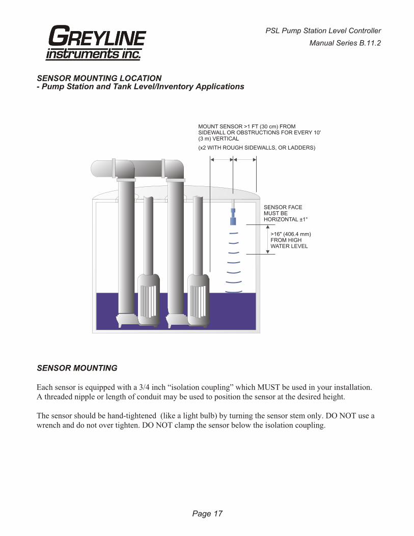
SENSOR MOUNTING LOCATION- Pump Station and Tank Level/Inventory Applications
SENSOR MOUNTING
Each sensor is equipped with a 3/4 inch “isolation coupling” which MUST be used in your installation.A threaded nipple or length of conduit may be used to position the sensor at the desired height.
The sensor should be hand-tightened (like a light bulb) by turning the sensor stem only. DO NOT use awrench and do not over tighten. DO NOT clamp the sensor below the isolation coupling.
Page 17
PSL Pump Station Level Controller
Manual Series B.11.2
SENSOR FACEMUST BEHORIZONTAL ±1°
MOUNT SENSOR >1 FT (30 cm) FROM SIDEWALL OR OBSTRUCTIONS FOR EVERY 10' (3 m) VERTICAL
(x2 WITH ROUGH SIDEWALLS, OR LADDERS)
>16" (406.4 mm)FROM HIGHWATER LEVEL

Page 18
PSL Pump Station Level Controller
Manual Series B.11.2
4" OR 6" BLIND FLANGETAPPED ¾" NPT
FLEXIBLECONDUIT
JUNCTIONBOX
(OPTION JB)
ISOLATIONCOUPLING(SUPPLIED)MUST BEUSED
DO NOTCLAMP IN
THIS AREA
¾" NPTNIPPLE
FLANGE MOUNT
ISOLATIONCOUPLING(SUPPLIED)MUST BEUSED
DO NOTCLAMP IN
THIS AREA
CLAMP
3/4"CONDUIT
CROSS BAR MOUNT
ISOLATIONCOUPLING(SUPPLIED)MUST BEUSED
DO NOTCLAMP IN
THIS AREA
3/4" NPTNIPPLE
ANGLE MOUNT
ISOLATIONCOUPLING(SUPPLIED)MUST BEUSED
DO NOTCLAMP IN
THIS AREA
3/4"CONDUIT
CONDUIT MOUNT
Notes:
1. Use the ¾" NPT "Isolation Coupling" supplied and hand tighten only. Do not clamp sensor body or stem.
2. Locate the sensor 1 ft (30 cm) from the sidewall or obstruction for every 10 ft (3 m) depth.
3. Do not mount in direct sunlight.4. Extend sensor cable up to 500 ft
(150 m) with RG62AU coaxial only.
GRIND OR FILEPIPE EDGE
SMOOTH
STAND PIPE MOUNT
STANDPIPE LENGTHAS SHORT AS POSSIBLESTANDPIPE DIAMETERAS LARGE AS POSSIBLE
TYPICAL STANDPIPE:4” / 100 mm DIAMETER12” / 300 mm LENGTH
NARROW DIAMETERSTANDPIPES (<4” / 100 mm)MAY AFFECT ACCURACYOF READING
ENCLOSURE INSTALLATION
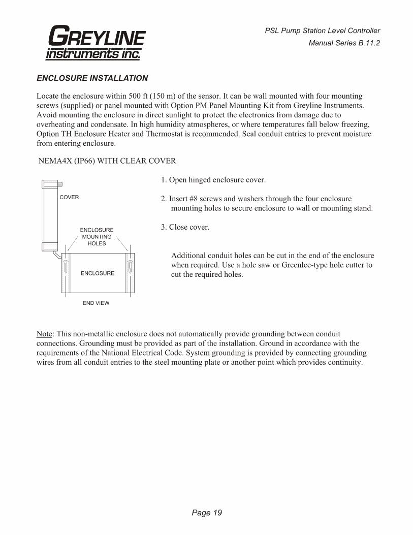
Locate the enclosure within 500 ft (150 m) of the sensor. It can be wall mounted with four mountingscrews (supplied) or panel mounted with Option PM Panel Mounting Kit from Greyline Instruments.Avoid mounting the enclosure in direct sunlight to protect the electronics from damage due tooverheating and condensate. In high humidity atmospheres, or where temperatures fall below freezing,Option TH Enclosure Heater and Thermostat is recommended. Seal conduit entries to prevent moisturefrom entering enclosure.
NEMA4X (IP66) WITH CLEAR COVER
1. Open hinged enclosure cover.
2. Insert #8 screws and washers through the four enclosuremounting holes to secure enclosure to wall or mounting stand.
3. Close cover.
Additional conduit holes can be cut in the end of the enclosurewhen required. Use a hole saw or Greenlee-type hole cutter tocut the required holes.
Note: This non-metallic enclosure does not automatically provide grounding between conduitconnections. Grounding must be provided as part of the installation. Ground in accordance with therequirements of the National Electrical Code. System grounding is provided by connecting groundingwires from all conduit entries to the steel mounting plate or another point which provides continuity.
Page 19
PSL Pump Station Level Controller
Manual Series B.11.2
END VIEW
COVER
ENCLOSURE
ENCLOSURE
MOUNTINGHOLES
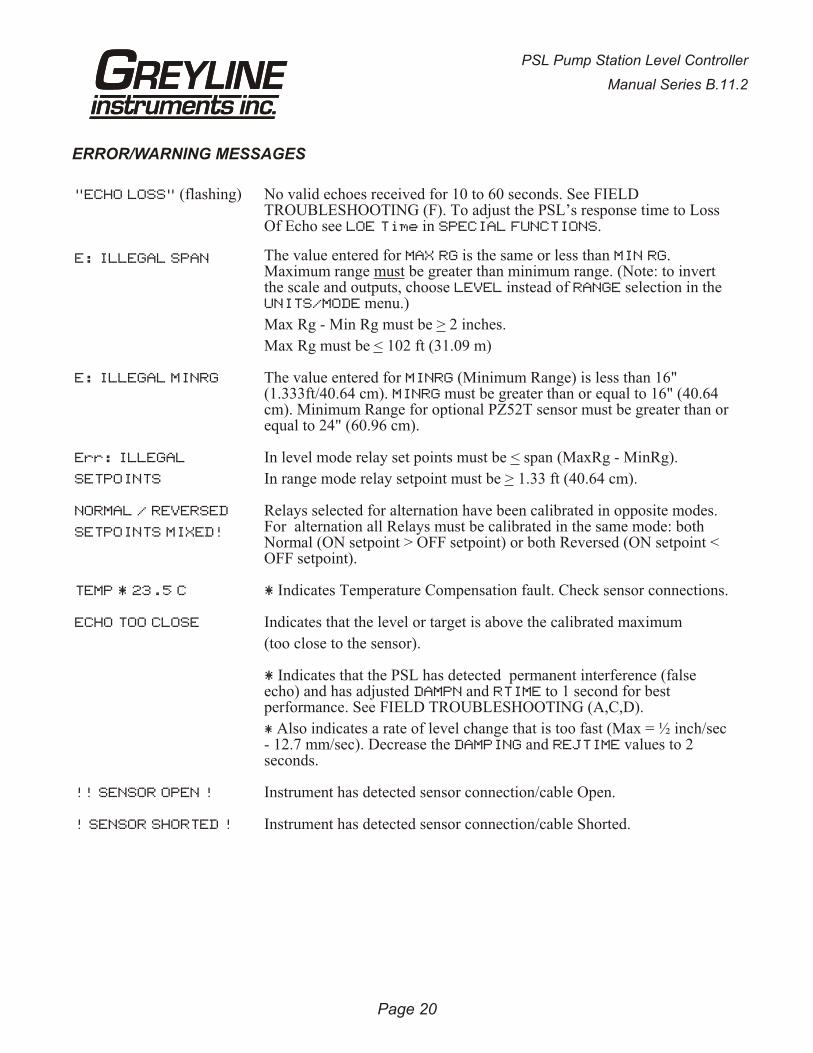
ERROR/WARNING MESSAGES
"ECHO LOSS" (flashing) No valid echoes received for 10 to 60 seconds. See FIELDTROUBLESHOOTING (F). To adjust the PSL’s response time to LossOf Echo see LOE Time in SPECIAL FUNCTIONS.
E: ILLEGAL SPAN The value entered for MAX RG is the same or less than MIN RG.Maximum range must be greater than minimum range. (Note: to invertthe scale and outputs, choose LEVEL instead of RANGE selection in theUNITS/MODE menu.)
Max Rg - Min Rg must be > 2 inches.
Max Rg must be < 102 ft (31.09 m)
E: ILLEGAL MINRG The value entered for MINRG (Minimum Range) is less than 16"(1.333ft/40.64 cm). MINRG must be greater than or equal to 16" (40.64cm). Minimum Range for optional PZ52T sensor must be greater than orequal to 24" (60.96 cm).
Err: ILLEGAL
SETPOINTS
In level mode relay set points must be < span (MaxRg - MinRg).
In range mode relay setpoint must be > 1.33 ft (40.64 cm).
NORMAL / REVERSED
SETPOINTS MIXED!
Relays selected for alternation have been calibrated in opposite modes.For alternation all Relays must be calibrated in the same mode: bothNormal (ON setpoint > OFF setpoint) or both Reversed (ON setpoint <OFF setpoint).
TEMP * 23.5 C * Indicates Temperature Compensation fault. Check sensor connections.
ECHO TOO CLOSE Indicates that the level or target is above the calibrated maximum
(too close to the sensor).
* Indicates that the PSL has detected permanent interference (false echo) and has adjusted DAMPN and RTIME to 1 second for bestperformance. See FIELD TROUBLESHOOTING (A,C,D).
* Also indicates a rate of level change that is too fast (Max = ½ inch/sec- 12.7 mm/sec). Decrease the DAMPING and REJTIME values to 2seconds.
!! SENSOR OPEN ! Instrument has detected sensor connection/cable Open.
! SENSOR SHORTED ! Instrument has detected sensor connection/cable Shorted.
Page 20
PSL Pump Station Level Controller
Manual Series B.11.2

FIELD TROUBLESHOOTING
SYMPTOMS CHECK
Display - full scale A
- zero B
- erratic - random C
- drifting up D
- drifting down E
ECHO LOSS prompt - flashing F
Calibration Non-Linear H
SYMPTOMS FAULTS SOLUTIONS
Unit “See’s” Wrong Target Due To:
A - sensor cover not removed - remove protective cover after installation
A,C,D,F - sensor not aimed correctly
A,D,F - dust/dirt buildup on sensor - clean carefully (do not scratch sensor face)
A,D,F - condensation on sensor - lower sensor- insulate sensor mounting location- increase MinRg (CALIBRATION menu) by
1-3” / 2.5-7.5 cm- wipe sensor face and body with Rain-X
A,D - sensor mounting stand pipe- too long / - too narrow- dirty / - gasket intruding
- lower Sensor below stand pipe intrusion
C,E - very turbulent level in tank - increase REJTIME (CALIBRATION menu)- change tank fill method
Unit Picks-Up Interference Due To:
A,C - noise from high pressure fill - install submerged fill pipe
A,D - sensor coupling over tightened - hand tighten only (like a light bulb)
A,D - sensor coupling not used - use coupling supplied
A - echo Strength setting adjusted toohigh
- decrease Echo Strength setting
C - other ultrasonic unit in closeproximity
- synchronize
Electrical interference:C - sensor cable connections reversed
C - through sensor cable - use properly grounded metal conduit
C - sensor cable extended andjunction not insulated
- use metal Junction Box
C - through enclosure - use metal enclosure
C - through 4-20mA output cable - use shielded twisted pair (shield to ACground)
PSL Pump Station Level Controller
Manual Series B.11.2
Page 21
C - wiring or installation close tovariable speed drive or inverter
- follow V.S.D. manufacturer’s instructionsfor Drive grounding, wiring and shielding
Unit Receives No Return Echo Due To:
C,F,E - foam on liquid surface - use stilling well. Increase ECHOSTRENGTH setting
B - target beyond MAXRG - recalibrate
F - sensor damaged - remove sensor from mounting and aim at aflat, stable target to test
Wiring Problems Due To Sensor Cable:A,C,F, - open circuit - check connections/continuity (8850 to
12700 ohms max./-30°C to +70°C )B,F - short circuit - check connections/continuity (8850 ohms
min.)F - too long (max 500 ft., 150 m)
C - bundled/run in conduit with power cable
C - sensor ground shorted toconduit/enclosure
- insulate
A - extended with wrong type of wire - use RG62A/U coaxial
C - close to high voltage/large motors
C - AC chassis/ground missing oninstrument power connections
Non-Linearity Due To:
H - vapour - dissipate fumes, Calibration in-situ
H - zero not set accurately - see “Zero Positioning of Sensor”
Page 22
PSL Pump Station Level Controller
Manual Series B.11.2

PZxx Series SensorsTroubleshooting
Resistance measured across the coaxial cable ends (between the shield and centre wire) by mulitmeterindicates ambient temperature.
Resistance vs. Temperature
Page 23
PSL Pump Station Level Controller
Manual Series B.11.2
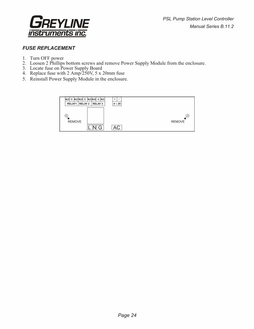
FUSE REPLACEMENT
1. Turn OFF power2. Loosen 2 Phillips bottom screws and remove Power Supply Module from the enclosure. 3. Locate fuse on Power Supply Board4. Replace fuse with 2 Amp/250V, 5 x 20mm fuse5. Reinstall Power Supply Module in the enclosure.
Page 24
PSL Pump Station Level Controller
Manual Series B.11.2
REMOVE REMOVE
RELAY1 RELAY 2 RELAY 3
C
L N G
4 20
C CN.N. N. N.N.N. CC O COO
AC

INSTALLATION CONSIDERATIONS IN NOISY ENVIRONMENTS
Greyline’s instruments are designed with a high degree of noise immunity for use in industrialenvironments. Noise interference can still occur if certain minimal considerations are not adhered towhen installing the equipment.
Noise
When relay contacts are used to switch inductive loads, such a auxiliary relays or solenoids, extremelylarge voltage spikes can be generated when the relay contact opens producing what is known asRadio-Frequency Interference or “RFI” or just “noise”.
These voltage spikes can also be coupled from power lines that are powering equipment that containsS.C.R. circuitry such as VSD controllers, or lines that are actuating AC or DC solenoids or actuators. There are three major ways that noise spikes can enter the instrument.
1. Via the AC power input lines.2. Via the Sensor input line.3. Via the output lines (relay connections and 4-20mA output)
Symptoms of RFI produced by relay activation
If the instrument shows the following symptoms suspect RFI.
- The Alphanumeric display (bottom display) blinks continuously as if power was being turn offand on (i.e instrument resets continuously).
- Keypad does not respond or instrument resets to run mode from inside the menu.- The instrument calibration is lost.- The message “MEM CORRUPTED” is shown.- Relays trip erratically.- Both digital displays go blank as if power was OFF.
Symptoms of noise on sensor input and/or 4-20mA lines
- Instruments readings are erratic or high when actual value is low- The Alphanumeric display (bottom display) blinks continuously as if power was being turned
off and on i.e instrument resets continuously.- Instrument “beeps” intermittently even if the Keypad is not pressed.
Page 25
PSL Pump Station Level Controller
Manual Series B.11.2
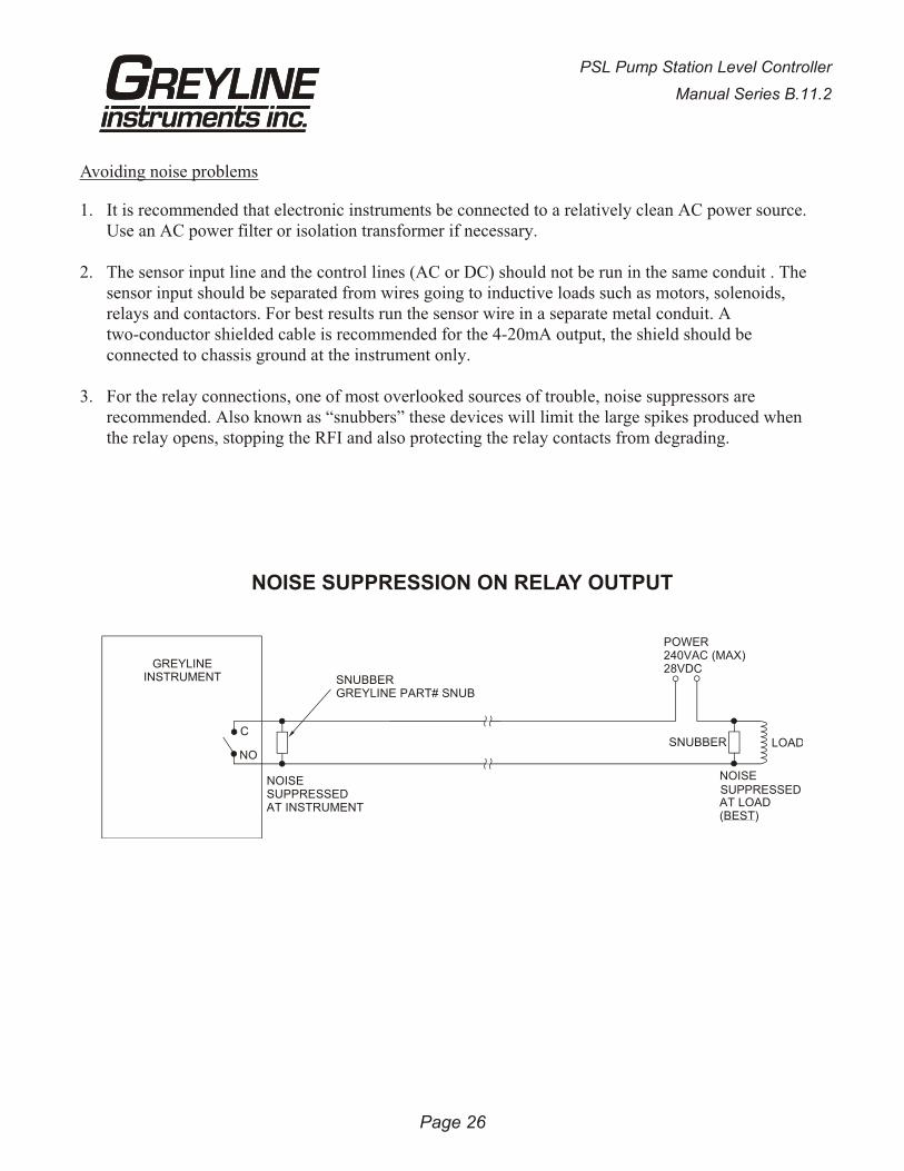
Avoiding noise problems
1. It is recommended that electronic instruments be connected to a relatively clean AC power source.Use an AC power filter or isolation transformer if necessary.
2. The sensor input line and the control lines (AC or DC) should not be run in the same conduit . Thesensor input should be separated from wires going to inductive loads such as motors, solenoids,relays and contactors. For best results run the sensor wire in a separate metal conduit. Atwo-conductor shielded cable is recommended for the 4-20mA output, the shield should beconnected to chassis ground at the instrument only.
3. For the relay connections, one of most overlooked sources of trouble, noise suppressors arerecommended. Also known as “snubbers” these devices will limit the large spikes produced whenthe relay opens, stopping the RFI and also protecting the relay contacts from degrading.
Page 26
PSL Pump Station Level Controller
Manual Series B.11.2
C
NO
NOISESUPPRESSEDAT INSTRUMENT
POWER240VAC (MAX)28VDC
NOISE
AT LOAD(BEST)
SNUBBERGREYLINE PART# SNUB
SNUBBER LOAD
GREYLINEINSTRUMENT
NOISE SUPPRESSION ON RELAY OUTPUT
SUPPRESSED
APPLICATIONS HOTLINE
For applications assistance, advice or information on any Greyline Instrument contact your SalesRepresentative, write to Greyline or phone the Applications Hotline below:
United States: Tel: 315-788-9500 Fax: 315-764-0419Canada: Tel: 613-938-8956 Fax: 613-938-4857Toll Free: 888-473-9546Email: [email protected] Site: http://www.greyline.com
Greyline Instruments Inc.
Canada USA:16456 Sixsmith Drive 105 Water StreetLong Sault, Ont. K0C 1P0 Massena, NY 13662
PSL Pump Station Level Controller
Manual Series B.11.2
Page 27
PRODUCT RETURN PROCEDURE
Instruments may be returned to Greyline for service or warranty repair.
1 Obtain an RMA Number from Greyline -Before shipping a product to the factory please contact Greyline by telephone, fax or email to obtainan RMA number (Returned Merchandise Authorization). This ensures fast service and correctbilling or credit.
When you contact Greyline please have the following information available:
1. Model number / Software Version
2. Serial number
3. Date of Purchase
4. Reason for return (description of fault or modification required)
5. Your name, company name, address and phone number
2 Clean the Sensor/Product -Important: unclean products will not be serviced and will be returned to the sender at their expense.
1. Rinse sensor and cable to remove debris.
2. If the sensor has been exposed to sewage, immerse both sensor and cable in a solution of 1 parthousehold bleach (Javex, Clorox etc.) to 20 parts water for 5 minutes. Important: do not immerse openend of sensor cable.
3. Dry with paper towels and pack sensor and cable in a sealed plastic bag.
4. Wipe the outside of the enclosure to remove dirt or deposits.
5. Return to Greyline for service.
3 Ship to Greyline -After obtaining an RMA number please ship the product to the appropriate address below:
Canadian and International USACustomers: Customers:
Greyline Instruments Inc. Greyline Instruments Inc.
16456 Sixsmith Drive 204 150th Avenue
Long Sault, Ont. K0C 1P0 Madeira Beach, FL 33708
RMA# RMA#
Page 28
PSL Pump Station Level Controller
Manual Series B.11.2

Page 29
PSL Pump Station Level Controller
Manual Series B.11.2
LIMITED WARRANTY____________________
Greyline Instruments warrants, to the original purchaser, itsproducts to be free from defects in material and workmanship for a period of one year from date of invoice. Greyline will replaceor repair, free of charge, any Greyline product if it has beenproven to be defective within the warranty period. This warranty does not cover any expenses incurred in the removal andre-installation of the product.
If a product manufactured by Greyline should prove defectivewithin the first year, return it freight prepaid to GreylineInstruments along with a copy of your invoice.
This warranty does not cover damages due to improperinstallation or handling, acts of nature, or unauthorized service.Modifications to or tampering with any part shall void thiswarranty. This warranty does not cover any equipment used inconnection with the product or consequential damages due to adefect in the product.
All implied warranties are limited to the duration of thiswarranty. This is the complete warranty by Greyline and noother warranty is valid against Greyline. Some states do notallow limitations on how long an implied warranty lasts orlimitation of incidental or consequential damages, so the abovelimitations or exclusions may not apply to you.
This warranty gives you specific legal rights, and you may alsohave other rights which vary from state to state.
Greyline Instruments Inc.
APPENDIX A - OPTIONS
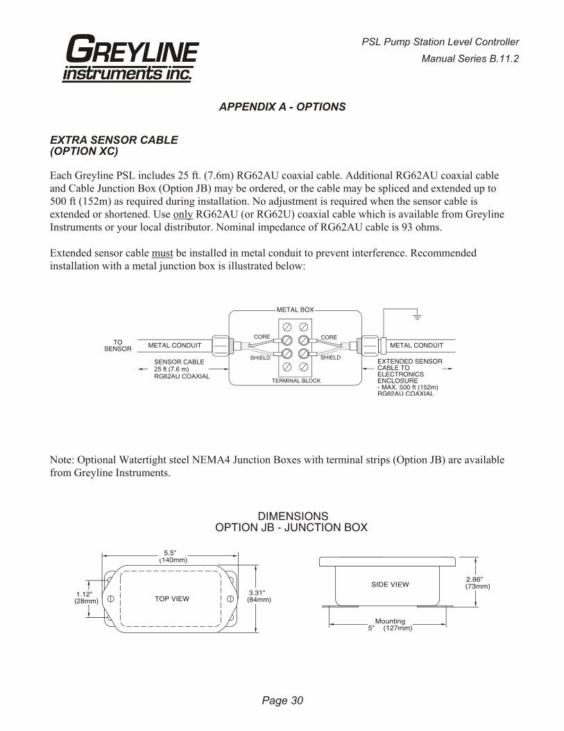
EXTRA SENSOR CABLE(OPTION XC)
Each Greyline PSL includes 25 ft. (7.6m) RG62AU coaxial cable. Additional RG62AU coaxial cableand Cable Junction Box (Option JB) may be ordered, or the cable may be spliced and extended up to500 ft (152m) as required during installation. No adjustment is required when the sensor cable isextended or shortened. Use only RG62AU (or RG62U) coaxial cable which is available from GreylineInstruments or your local distributor. Nominal impedance of RG62AU cable is 93 ohms.
Extended sensor cable must be installed in metal conduit to prevent interference. Recommendedinstallation with a metal junction box is illustrated below:
Note: Optional Watertight steel NEMA4 Junction Boxes with terminal strips (Option JB) are availablefrom Greyline Instruments.
Page 30
PSL Pump Station Level Controller
Manual Series B.11.2
SENSOR CABLE25 ft (7.6 m)RG62AU COAXIAL
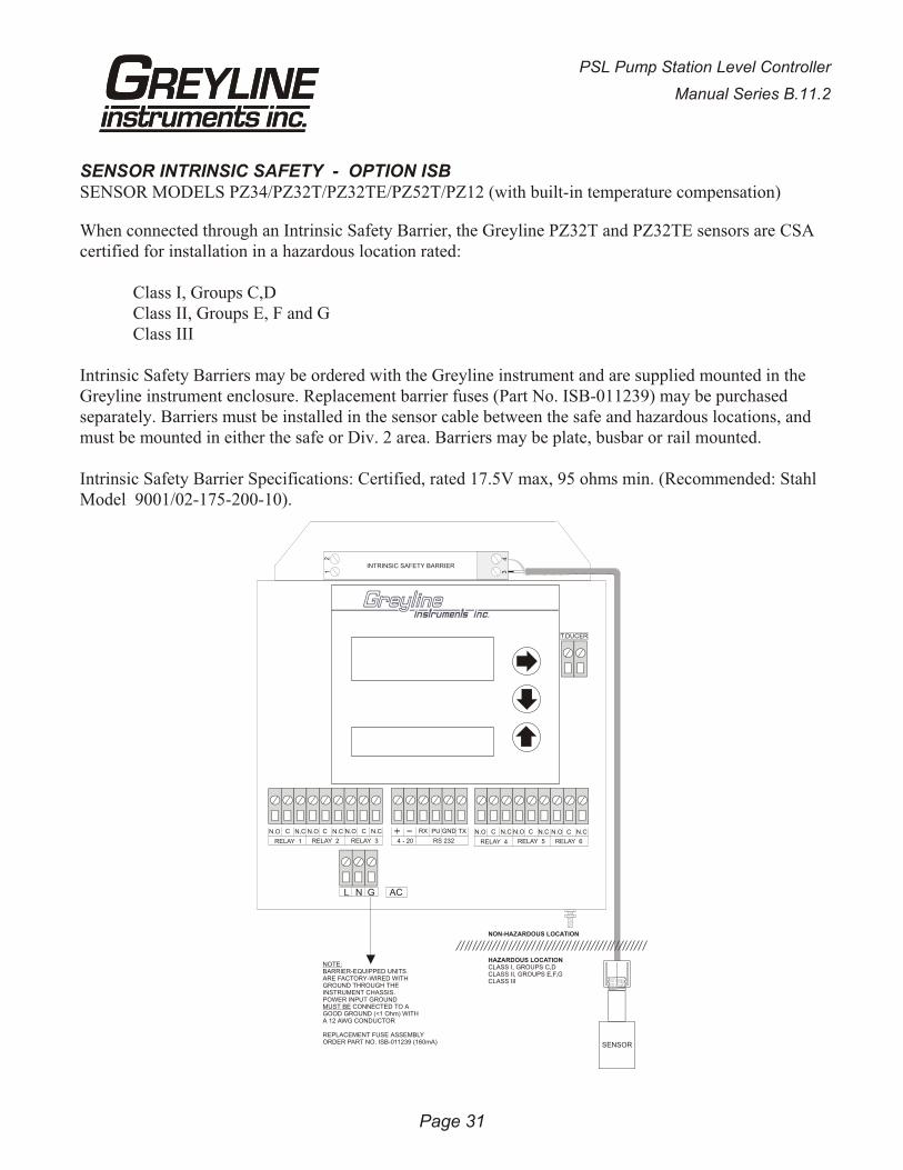
SENSOR INTRINSIC SAFETY - OPTION ISBSENSOR MODELS PZ34/PZ32T/PZ32TE/PZ52T/PZ12 (with built-in temperature compensation)
When connected through an Intrinsic Safety Barrier, the Greyline PZ32T and PZ32TE sensors are CSAcertified for installation in a hazardous location rated:
Class I, Groups C,DClass II, Groups E, F and GClass III
Intrinsic Safety Barriers may be ordered with the Greyline instrument and are supplied mounted in theGreyline instrument enclosure. Replacement barrier fuses (Part No. ISB-011239) may be purchasedseparately. Barriers must be installed in the sensor cable between the safe and hazardous locations, andmust be mounted in either the safe or Div. 2 area. Barriers may be plate, busbar or rail mounted.
Intrinsic Safety Barrier Specifications: Certified, rated 17.5V max, 95 ohms min. (Recommended: StahlModel 9001/02-175-200-10).
Page 31
PSL Pump Station Level Controller
Manual Series B.11.2
T.DUCER
N.O C N.C N.O C N.C N.O C N.C
RELAY 1 RELAY 2 RELAY 3
L N G AC
RX PU GND TX
RS 232
N.O C N.C N.O C N.C
RELAY 4 RELAY 5
N.O C N.C
RELAY 64 - 20
34
12
NOTE:BARRIER-EQUIPPED UNITSARE FACTORY-WIRED WITHGROUND THROUGH THEINSTRUMENT CHASSIS.POWER INPUT GROUNDMUST BE CONNECTED TO AGOOD GROUND (<1 Ohm) WITHA 12 AWG CONDUCTOR
REPLACEMENT FUSE ASSEMBLYORDER PART NO. ISB-011239 (160mA)
NON-HAZARDOUS LOCATION
HAZARDOUS LOCATIONCLASS I, GROUPS C,DCLASS II, GROUPS E,F,GCLASS III
INTRINSIC SAFETY BARRIER
SENSOR
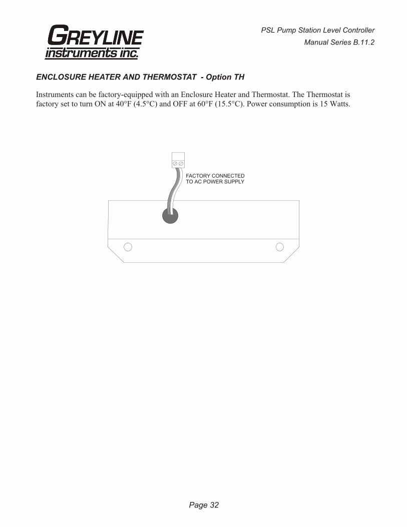
ENCLOSURE HEATER AND THERMOSTAT - Option TH
Instruments can be factory-equipped with an Enclosure Heater and Thermostat. The Thermostat isfactory set to turn ON at 40°F (4.5°C) and OFF at 60°F (15.5°C). Power consumption is 15 Watts.
PSL Pump Station Level Controller
Manual Series B.11.2
Page 32
FACTORY CONNECTEDTO AC POWER SUPPLY
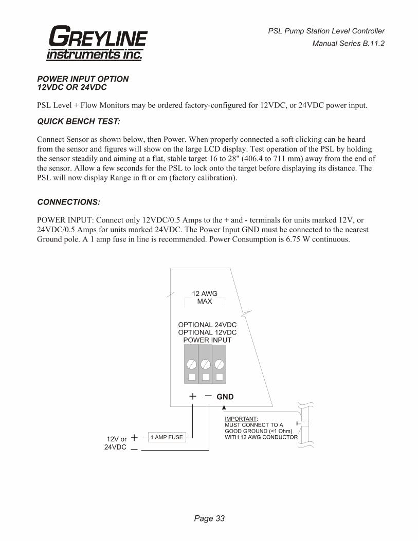
POWER INPUT OPTION12VDC OR 24VDC
PSL Level + Flow Monitors may be ordered factory-configured for 12VDC, or 24VDC power input.
QUICK BENCH TEST:
Connect Sensor as shown below, then Power. When properly connected a soft clicking can be heardfrom the sensor and figures will show on the large LCD display. Test operation of the PSL by holdingthe sensor steadily and aiming at a flat, stable target 16 to 28" (406.4 to 711 mm) away from the end ofthe sensor. Allow a few seconds for the PSL to lock onto the target before displaying its distance. ThePSL will now display Range in ft or cm (factory calibration).
CONNECTIONS:
POWER INPUT: Connect only 12VDC/0.5 Amps to the + and - terminals for units marked 12V, or24VDC/0.5 Amps for units marked 24VDC. The Power Input GND must be connected to the nearestGround pole. A 1 amp fuse in line is recommended. Power Consumption is 6.75 W continuous.
Page 33
PSL Pump Station Level Controller
Manual Series B.11.2
GND
12 AWGMAX
OPTIONAL 24VDCOPTIONAL 12VDC
POWER INPUT
IMPORTANT:MUST CONNECT TO AGOOD GROUND (<1 Ohm) WITH 12 AWG CONDUCTOR
24VDC12V or 1 AMP FUSE
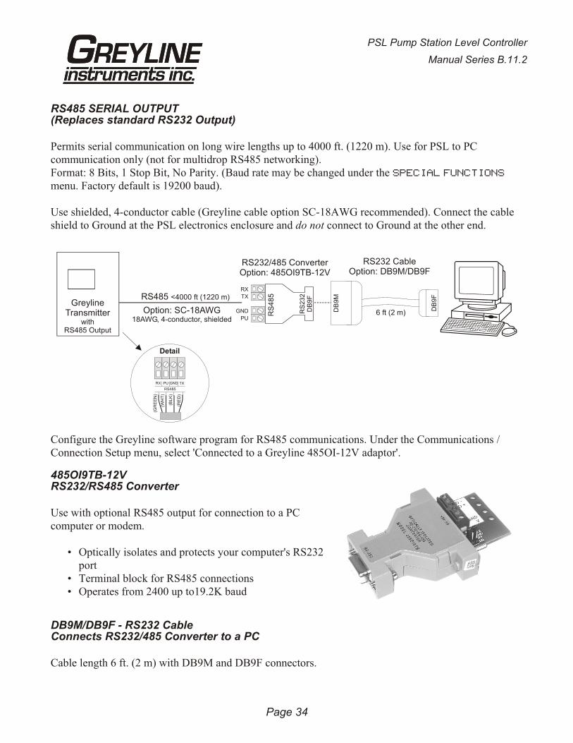
RS485 SERIAL OUTPUT(Replaces standard RS232 Output)
Permits serial communication on long wire lengths up to 4000 ft. (1220 m). Use for PSL to PCcommunication only (not for multidrop RS485 networking).Format: 8 Bits, 1 Stop Bit, No Parity. (Baud rate may be changed under the SPECIAL FUNCTIONS
menu. Factory default is 19200 baud).
Use shielded, 4-conductor cable (Greyline cable option SC-18AWG recommended). Connect the cableshield to Ground at the PSL electronics enclosure and do not connect to Ground at the other end.
Configure the Greyline software program for RS485 communications. Under the Communications /Connection Setup menu, select 'Connected to a Greyline 485OI-12V adaptor'.
485OI9TB-12VRS232/RS485 Converter
Use with optional RS485 output for connection to a PCcomputer or modem.
• Optically isolates and protects your computer's RS232port
• Terminal block for RS485 connections• Operates from 2400 up to19.2K baud
DB9M/DB9F - RS232 CableConnects RS232/485 Converter to a PC
Cable length 6 ft. (2 m) with DB9M and DB9F connectors.
PSL Pump Station Level Controller
Manual Series B.11.2
Page 34
GreylineTransmitter
withRS485 Output
RS485 <4000 ft (1220 m)
Detail
RX
RS485
PU GND TX
(GR
EE
N)
(WH
T)
(BL
K)
(RE
D)
Option: SC-18AWG18AWG, 4-conductor, shielded
DB
9F
DB
9M
RS232 CableOption: DB9M/DB9F
6 ft (2 m)
RS232/485 ConverterOption: 485OI9TB-12V
RX
TX
GND
PU
RS
48
5
RS
23
2D
B9
F
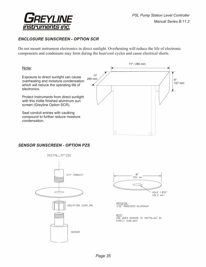
ENCLOSURE SUNSCREEN - OPTION SCR
Do not mount instrument electronics in direct sunlight. Overheating will reduce the life of electroniccomponents and condensate may form during the heat/cool cycles and cause electrical shorts.
SENSOR SUNSCREEN - OPTION PZS
PSL Pump Station Level Controller
Manual Series B.11.2
Page 35
Note:
Exposure to direct sunlight can causeoverheating and moisture condensationwhich will reduce the operating life ofelectronics.
Protect Instruments from direct sunlightwith this iridite finished aluminum sunscreen (Greyline Option SCR).
Seal conduit entries with caulkingcompound to further reduce moisturecondensation.
11" / 280 mm
5"127 mm
11"280 mm
APPENDIX B - APPLICATIONS BACKGROUND
Conditions in the tank or channel where the ultrasonic sensor is installed can affect the performance,range and accuracy of the system. The following notes are for general reference. Contact GreylineInstruments or your local representative for specific information on your application.
FOAM - Solid or dense surfaces such as a smooth liquid surface will give the best echos in an ultrasonic level measuring system. Foam acts as a sound insulator and may eliminate, or reduce the strength of anecho. Measurement range may be reduced in a system where foam is present. Ultrasonics are notrecommended where thick dense foam is continually present. Thin layers of light foam (½ in. or less)can generally be disregarded. Use a stilling well in open channel applications.
LIQUIDS - The PSL is ideal to monitor tank liquid level or inventory. Caustic, corrosive or very viscous liquids can be monitored without contacting the liquid.
SOLIDS - The PSL will measure most granular material and powders as well as liquids. Powders willnot generally provide the same echo strength as liquids. Therefore maximum expected range should bereduced to approximately 20 feet (6 m) for powders. There are many exceptions to this rule andinstallation of a test system is recommended when in doubt.
DUST - Any obstructions to the sound will affect performance of the system. In silo’s where heavyconcentrations of dust are expected ultrasonics may not work. Where moderate dust is encounteredcare should be taken to mount the sensor in a position where dust accumulation will be minimized andwhere the sensor can be cleaned if necessary.
SENSOR TEMPERATURE - The standard sensor model PZ34 supplied with each Pump Station LevelController includes a built-in temperature sensor. The PSL automatically compensates for temperaturefluctuations to retain high accuracy. Note the operating temperature ranges listed in the productspecifications section. Do not exceed the sensor temperature ratings or damage may occur.
ELECTRONICS TEMPERATURE - Note operating temperature ranges listed in the productspecifications. Temperatures higher than the maximum shown can reduce the operating life of the electronics. Moisture condensation from those temperatures below the range shown can also damageelectronics components. In cold or outdoor environments the optional factory-installed enclosure heater and thermostat is recommended.
NOISE - Because the PSL’s sensor operates at high sound frequency, regular process noise or vibrationwill not affect the system. Sensors installed in close proximity to one another in the same tank may “cross-talk” and should be synchronized.
VAPOUR - May affect but it can be compensated for by calibration in-situ. Severe vapourstratification can cause false echoes. Variable vapour cannot be compensated.
CHEMICAL COMPATIBILITY - The PSL’s Sensor is constructed of very durable materials with broad compatibilities. Tank contents should be checked for their compatibility with PVC. An all-teflon sensoris available for corrosive applications.
Page 36
PSL Pump Station Level Controller
Manual Series B.11.2

VOLUME CALCULATION FOR ROUND TANKS: 3.142 x R² x HR = TANK RADIUS (½ TANK DIAMETER)H = TANK HEIGHT
Page 37
PSL Pump Station Level Controller
Manual Series B.11.2
CONVERSION
GUIDE
FROM TO MULTIPLY BY
US GALLONS CUBIC FEET 0.1337
US GALLONS IMPERIAL GALS 0.8327
US GALLONS LITRES 3.785
US GALLONS CUBIC METERS 0.003785
LITRES/SEC GPM 15.85
LITRES CUBIC METERS 0.001
BARRELS US GALLONS 42
BARRELS IMPERIAL GALS 34.9726
BARRELS LITRES 158.9886
INCHES MM 25.4
DEGREES F DEGREES C (°F-32) x 0.556
POUNDS KILOGRAMS 0.453
PSI BAR 0.0676
FOOT² METER² 0.0929
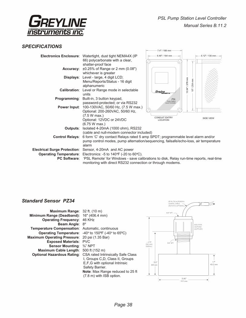
SPECIFICATIONS
Electronics Enclosure: Watertight, dust tight NEMA4X (IP66) polycarbonate with a clear,shatter-proof face
Accuracy: ±0.25% of Range or 2 mm (0.08")whichever is greater
Displays: Level - large, 4 digit LCD;Menu/Reports/Status - 16 digitalphanumeric
Calibration: Level or Range mode in selectableunits
Programming: Built-in, 3 button keypad,password-protected; or via RS232
Power Input: 100-130VAC, 50/60 Hz, (7.5 W max.)Optional: 200-260VAC, 50/60 Hz,(7.5 W max.)Optional: 12VDC or 24VDC(6.75 W max.)
Outputs: Isolated 4-20mA (1000 ohm), RS232(cable and null-modem connector included)
Control Relays: 6 form ‘C’ dry contact Relays rated 5 amp SPDT; programmable level alarm and/orpump control modes, pump alternation/sequencing, failsafe/echo-loss, air temperaturealarm
Electrical Surge Protection: Sensor, 4-20mA and AC power
Operating Temperature: Electronics: -5 to 140°F (-20 to 60°C).PC Software: ‘PSL Remote’ for Windows - save calibrations to disk, Relay run-time reports, real-time
monitoring with direct RS232 connection or through modems.
Standard Sensor PZ34
Maximum Range: 32 ft. (10 m)Minimum Range (Deadband): 16" (406.4 mm)
Operating Frequency: 46 KHzBeam Angle: 8º
Temperature Compensation: Automatic, continuous
Operating Temperature: -40° to 150ºF (-40° to 65ºC)Maximum Operating Pressure: 20 psi (1.35 Bar)
Exposed Materials: PVCSensor Mounting: ¾” NPT
Maximum Cable Length: 500 ft (152 m)Optional Hazardous Rating: CSA rated Intrinsically Safe Class
I, Groups C,D, Class II, GroupsE,F,G with optional IntrinsicSafety Barrier.Note: Max Range reduced to 25 ft (7.8 m) with ISB option.
PSL Pump Station Level Controller
Manual Series B.11.2
Page 38
7.4 / 188 mm"
6.46 / 164 mm"
10.9
4"
/ 27
8 m
m
10
/ 2
54
mm
"
CONDUIT ENTRYLOCATION
SIDE VIEW
5.12 / 130 mm"
PSLPump Station
Level Controller
25 ft (7.6 m) RG62AUCOAXIAL CABLE(50 ft 15 m OPTIONAL)
3/4“ NPT
ISOLATIONCOUPLING(SUPPLIED)
3/4" NPT
3.5”89 mm
3.95”100 mm
1.7”43.2 mm
~ 4.75"(120 mm)OVERALL
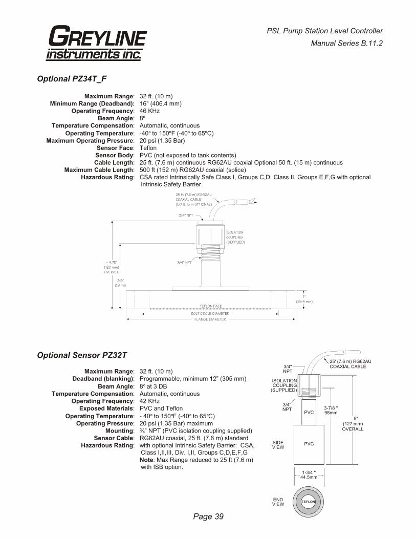
Optional PZ34T_F
Maximum Range: 32 ft. (10 m)Minimum Range (Deadband): 16" (406.4 mm)
Operating Frequency: 46 KHzBeam Angle: 8º
Temperature Compensation: Automatic, continuous
Operating Temperature: -40° to 150ºF (-40° to 65ºC)Maximum Operating Pressure: 20 psi (1.35 Bar)
Sensor Face: TeflonSensor Body: PVC (not exposed to tank contents)Cable Length: 25 ft. (7.6 m) continuous RG62AU coaxial Optional 50 ft. (15 m) continuous
Maximum Cable Length: 500 ft (152 m) RG62AU coaxial (splice)Hazardous Rating: CSA rated Intrinsically Safe Class I, Groups C,D, Class II, Groups E,F,G with optional
Intrinsic Safety Barrier.
Optional Sensor PZ32T
Maximum Range: 32 ft. (10 m)Deadband (blanking): Programmable, minimum 12” (305 mm)
Beam Angle: 8° at 3 DBTemperature Compensation: Automatic, continuous
Operating Frequency: 42 KHzExposed Materials: PVC and Teflon
Operating Temperature: - 40° to 150°F (-40° to 65°C)Operating Pressure: 20 psi (1.35 Bar) maximum
Mounting: ¾” NPT (PVC isolation coupling supplied)Sensor Cable: RG62AU coaxial, 25 ft. (7.6 m) standard
Hazardous Rating: with optional Intrinsic Safety Barrier: CSA,Class I,II,III, Div. I,II, Groups C,D,E,F,GNote: Max Range reduced to 25 ft (7.6 m)with ISB option.
Page 39
PSL Pump Station Level Controller
Manual Series B.11.2
~ 4.75"(120 mm)OVERALL
3.5"89 mm
25 ft (7.6 m) RG62AUCOAXIAL CABLE(50 ft 15 m OPTIONAL)
3/4“ NPT
ISOLATIONCOUPLING(SUPPLIED)
3/4” NPT
1"(25.4 mm)
BOLT CIRCLE DIAMETER
TEFLON FACE
FLANGE DIAMETER
1-3/4 "44.5mm
3-7/8 "98mm
3/4" NPT
PVC
PVC
SIDEVIEW
ENDVIEW
5"(127 mm)OVERALL
3/4"NPT
ISOLATIONCOUPLING
(SUPPLIED)
TEFLOTEFLON
25' (7.6 m) RG62AUCOAXIAL CABLE
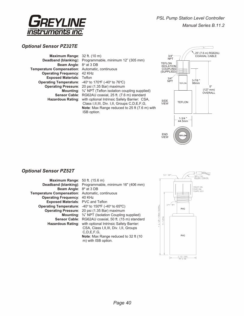
Optional Sensor PZ32TE
Maximum Range: 32 ft. (10 m)Deadband (blanking): Programmable, minimum 12” (305 mm)
Beam Angle: 8° at 3 DBTemperature Compensation: Automatic, continuous
Operating Frequency: 42 KHzExposed Materials: Teflon
Operating Temperature: -40° to 170°F (-40° to 76°C)Operating Pressure: 20 psi (1.35 Bar) maximum
Mounting: ¾” NPT (Teflon isolation coupling supplied)Sensor Cable: RG62AU coaxial, 25 ft. (7.6 m) standard
Hazardous Rating: with optional Intrinsic Safety Barrier: CSA,Class I,II,III, Div. I,II, Groups C,D,E,F,G,Note: Max Range reduced to 25 ft (7.6 m) withISB option.
Optional Sensor PZ52T
Maximum Range: 50 ft. (15.6 m)Deadband (blanking): Programmable, minimum 16" (406 mm)
Beam Angle: 8º at 3 DBTemperature Compensation: Automatic, continuous
Operating Frequency: 40 KHzExposed Materials: PVC and Teflon
Operating Temperature: -40° to 150ºF (-40° to 65ºC)Operating Pressure: 20 psi (1.35 Bar) maximum
Mounting: ¾” NPT (Isolation Coupling supplied)Sensor Cable: RG62AU coaxial, 50 ft. (15 m) standard
Hazardous Rating: with optional Intrinsic Safety Barrier: CSA, Class I,II,III, Div. I,II, GroupsC,D,E,F,G,Note: Max Range reduced to 32 ft (10m) with ISB option.
Page 40
PSL Pump Station Level Controller
Manual Series B.11.2
1-3/4 "44.5mm
3-7/8 "98mm
3/4" NPT
SIDEVIEW
ENDVIEW
5"(127 mm)OVERALL
3/4"NPT
ISOLATIONCOUPLING
(SUPPLIED)
TEFLOTEFLON
TEFLON
TEFLON
TEFLON
25' (7.6 m) RG62AUCOAXIAL CABLE
PVCPVC
PVCPVC
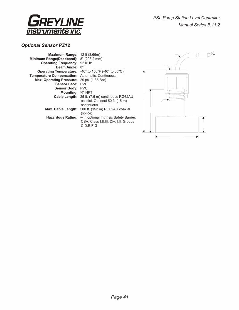
Optional Sensor PZ12
Maximum Range: 12 ft (3.66m)Minimum Range(Deadband): 8" (203.2 mm)
Operating Frequency: 92 KHzBeam Angle: 8°
Operating Temperature: -40° to 150°F (-40° to 65°C)Temperature Compensation: Automatic, Continuous
Max. Operating Pressure: 20 psi (1.35 Bar)Sensor Face: PVCSensor Body: PVC
Mounting: ¾" NPTCable Length: 25 ft. (7.6 m) continuous RG62AU
coaxial. Optional 50 ft. (15 m)continuous
Max. Cable Length: 500 ft. (152 m) RG62AU coaxial(splice)
Hazardous Rating: with optional Intrinsic Safety Barrier: CSA, Class I,II,III, Div. I,II, GroupsC,D,E,F,G
Page 41
PSL Pump Station Level Controller
Manual Series B.11.2
25 ft (7.6 m) RG6 2AUCOAXIAL CABLE(50 ft 15 m OPTIONAL)
3/4“ NPT
ISOLATIONCOUPLING(SUPPLIED)
3/4" NPT
1"(25.4 mm)
~ 3.9 "(99 mm)OVERALL
2.75"70 mm
2.75" (70 mm)
UN
IT
S /
MO
DE
Ra
ng
e L
ev
el
ft
i
n m
c
m %
St
or
e?
Y
es
CA
LI
BR
AT
IO
N
Mi
nR
g 1
2.
00
in
Ma
xR
g 1
44
.0
in
4m
A @
0
.0
%
20
mA
@ 1
00
.0
0%
Da
mp
in
g 2
0 %
Re
jT
im
e 8
s
St
or
e?
Y
es
RE
LA
Y R
UN
TI
ME
S
R1
0
0h
0
0m
0
0s
R6
0
0h
0
0m
0
0s
PA
SS
WO
RD
:0
0S
PE
CI
AL
FU
NC
TI
ON
PS
L V
2.
77
RE
LA
Y P
AR
AM
ET
ER
S
R2
to
R5
**
*
ST
OR
IN
G *
**
**
*
ST
OR
IN
G *
**
Vi
ew
Co
de
s?
Y
es
Ta
g 0
0
LO
E T
im
e 3
0 s
Rs
t R
ly
Lo
g?
Y
es
Si
mu
l 0
.0
0%
4m
A A
DJ
4.
00
0
20
mA
AD
J 2
0.
00
0
Ne
w P
as
sw
or
d:
00
Co
m 2
4 4
8 9
6 1
92
St
or
e?
Y
es
**
* S
TO
RI
NG
*
**
12
34
56
78
90
12
34
56
Te
mp
20
.3
Cº
Mi
n T
em
p
2
0.
0Cº
Ma
x T
em
p
2
3.
0Cº
DI
SP
LA
Y
C
Fº
º
De
fa
ul
ts
?
Y
es
RU
N
Le
ve
l:
2
.0
00
ft
EC
9
Se
ria
l # _
__
__
__
__
__
__
__
__
__
__
__
Da
te: _
__
__
__
__
__
__
__
__
__
__
__
__
FL
OW
MO
DE
ON
LY
RE
LA
YS
:1
2 3
4 5
6
To
t:
IS
B?
: N
o
Y
es
PS
L -
CA
LIB
RA
TIO
N R
EC
OR
D
SE
E
FO
LL
OW
ING
PA
GE
S
R1 Off 35.0 ft
R1 On 3.00 ft
R1 Off 35.0°C
R1 On 40.0°C
R1 Function Off R1 Function Temp R1 Function Level
R1 Mode Lo AlmR1 Mode Pump R1 Mode Hi Alm
R1 LOE Off R1 LOE On R1 LOE Hold
R2 Off 35.0 ft
R2 On 3.00 ft
R2 Off 35.0°C
R2 On 40.0°C
R2 Function Off R2 Function Temp R2 Function Level
R2 Mode Lo AlmR2 Mode Pump R2 Mode Hi Alm
R2 LOE Off R2 LOE On R2 LOE Hold
R3 Off 35.0 ft
R3 On 3.00 ft
R3 Off 35.0°C
R3 On 40.0°C
R3 Function Off R3 Function Temp R3 Function Level
R3 Mode Lo AlmR3 Mode Pump R3 Mode Hi Alm
R3 LOE Off R3 LOE On R3 LOE Hold
RELAY PARAMETERS SPECIAL FUNCTIONCALIBRATION
cont'd next page

R4 Off 35.0 ft
R4 On 3.00 ft
R4 Off 35.0°C
R4 On 40.0°C
R4 Function Off R4 Function Temp R4 Function Level
R4 Mode Lo AlmR4 Mode Pump R4 Mode Hi Alm
R4 LOE Off R4 LOE On R4 LOE Hold
R5 Off 35.0 ft
R5 On 3.00 ft
R5 Off 35.0°C
R5 On 40.0°C
R5 Function Off R5 Function Temp R5 Function Level
R5 Mode Lo AlmR5 Mode Pump R5 Mode Hi Alm
R5 LOE Off R5 LOE On R5 LOE Hold
R6 Off 35.0 ft
R6 On 3.00 ft
R6 Off 35.0°C
R6 On 40.0°C
R6 Function Off R6 Function Temp R6 Function Level
R6 Mode Lo AlmR6 Mode Pump R6 Mode Hi Alm
R6 LOE Off R6 LOE On R6 LOE Hold
On Delay 15 s
ForceALT 0 m
Store? Yes
Forced Alternation applies toRelays selected for alternation
On Delay Applies torelays in Pump mode
*** STORING ***
ALT (123456)

www.greyline.com