Embed Size (px)
Citation preview
User’s GuideLaser Diode Controller Mainframe
LDC-3916
70025606 July 2015
ILX Lightwave · 31950 Frontage Road · Bozeman, MT, U.S.A. 59715 · U.S. & Canada: 1-800-459-9459 · International Inquiries: 406-556-2481 · Fax 406-586-9405
www.newport.com/ilxlightwave

TA B L E O F C O N T E N T S
07_15 LDC-3916 i
TABLE OF CONTENTS
Safety Information and the Manual . . . . . . . . . . . . . . . . . . . . . . . . . . . . . . . . .vii
General Safety Considerations . . . . . . . . . . . . . . . . . . . . . . . . . . . . . . . . . . . .vii
Safety Marking Symbols . . . . . . . . . . . . . . . . . . . . . . . . . . . . . . . . . . . . . . . . . ix
Comments, Suggestions, and Problems . . . . . . . . . . . . . . . . . . . . . . . . . . . . xi
Chapter 1 Introduction
Product Overview . . . . . . . . . . . . . . . . . . . . . . . . . . . . . . . . . . . . . . . . . . . . . . . . 1
Initial Inspection . . . . . . . . . . . . . . . . . . . . . . . . . . . . . . . . . . . . . . . . . . . . . . . 2
Installing the LDC-3916 Laser Diode Controller . . . . . . . . . . . . . . . . . . . . . . . . 3
Grounding Requirements . . . . . . . . . . . . . . . . . . . . . . . . . . . . . . . . . . . . . . . 3AC Line Power Requirements . . . . . . . . . . . . . . . . . . . . . . . . . . . . . . . . . . . 3RS-232 Connectors . . . . . . . . . . . . . . . . . . . . . . . . . . . . . . . . . . . . . . . . . . . 3GPIB Connector . . . . . . . . . . . . . . . . . . . . . . . . . . . . . . . . . . . . . . . . . . . . . . 3The GPIB Address . . . . . . . . . . . . . . . . . . . . . . . . . . . . . . . . . . . . . . . . . . . . 4
Tilt-Foot Adjustment . . . . . . . . . . . . . . . . . . . . . . . . . . . . . . . . . . . . . . . . . . . . 4
Rack Mounting . . . . . . . . . . . . . . . . . . . . . . . . . . . . . . . . . . . . . . . . . . . . . . . . 4
LDC-3916 Orientation . . . . . . . . . . . . . . . . . . . . . . . . . . . . . . . . . . . . . . . . . . . 5
Specifications . . . . . . . . . . . . . . . . . . . . . . . . . . . . . . . . . . . . . . . . . . . . . . . . . . . 7
Modules and Accessories . . . . . . . . . . . . . . . . . . . . . . . . . . . . . . . . . . . . . . 8
Chapter 2 Operations
Applying Power to Your Laser Diode Controller . . . . . . . . . . . . . . . . . . . . . . . 9
The Power On Sequence . . . . . . . . . . . . . . . . . . . . . . . . . . . . . . . . . . . . . . 9The Power On State . . . . . . . . . . . . . . . . . . . . . . . . . . . . . . . . . . . . . . . . . 10
TA B L E O F C O N T E N T S
ii LDC-3916
LDC-3916 Front Panel Controls . . . . . . . . . . . . . . . . . . . . . . . . . . . . . . . . . . . . 11
Display Controls . . . . . . . . . . . . . . . . . . . . . . . . . . . . . . . . . . . . . . . . . . . . . 11Adjust Controls . . . . . . . . . . . . . . . . . . . . . . . . . . . . . . . . . . . . . . . . . . . . . 12
Using the LDC-3916 Menu Structure . . . . . . . . . . . . . . . . . . . . . . . . . . . . . . . . 14
Main Menu . . . . . . . . . . . . . . . . . . . . . . . . . . . . . . . . . . . . . . . . . . . . . . . . . . 14
Channel Menu . . . . . . . . . . . . . . . . . . . . . . . . . . . . . . . . . . . . . . . . . . . . . . . 14System Configuration . . . . . . . . . . . . . . . . . . . . . . . . . . . . . . . . . . . . . . . . 15Communications Configuration . . . . . . . . . . . . . . . . . . . . . . . . . . . . . . . . . 15Display Configuration . . . . . . . . . . . . . . . . . . . . . . . . . . . . . . . . . . . . . . . . . 16Calibration . . . . . . . . . . . . . . . . . . . . . . . . . . . . . . . . . . . . . . . . . . . . . . . . . 17Save and Recall . . . . . . . . . . . . . . . . . . . . . . . . . . . . . . . . . . . . . . . . . . . . . 18All Channel Menu . . . . . . . . . . . . . . . . . . . . . . . . . . . . . . . . . . . . . . . . . . . 19Setting All TEC . . . . . . . . . . . . . . . . . . . . . . . . . . . . . . . . . . . . . . . . . . . . . 20Status Menu . . . . . . . . . . . . . . . . . . . . . . . . . . . . . . . . . . . . . . . . . . . . . . . . 21
Modulating the Controller Laser Current Sources . . . . . . . . . . . . . . . . . . . . 24
Chapter 3 Operating In Remote Control
GPIB Configuration . . . . . . . . . . . . . . . . . . . . . . . . . . . . . . . . . . . . . . . . . . . . . . 27
Data and Interface Messages . . . . . . . . . . . . . . . . . . . . . . . . . . . . . . . . . . 27RS-232 Configuration . . . . . . . . . . . . . . . . . . . . . . . . . . . . . . . . . . . . . . . . 30Changing Operation from Local to Remote . . . . . . . . . . . . . . . . . . . . . . . . 30GPIB Versus RS-232 Communications . . . . . . . . . . . . . . . . . . . . . . . . . . . 31
Laser Diode Controller Command Set . . . . . . . . . . . . . . . . . . . . . . . . . . . . . . 32
Command Syntax . . . . . . . . . . . . . . . . . . . . . . . . . . . . . . . . . . . . . . . . . . . . . 32Letters . . . . . . . . . . . . . . . . . . . . . . . . . . . . . . . . . . . . . . . . . . . . . . . . . . . . 32White Space . . . . . . . . . . . . . . . . . . . . . . . . . . . . . . . . . . . . . . . . . . . . . . . 32Terminators . . . . . . . . . . . . . . . . . . . . . . . . . . . . . . . . . . . . . . . . . . . . . . . . 33Command Separators . . . . . . . . . . . . . . . . . . . . . . . . . . . . . . . . . . . . . . . . 33Parameters . . . . . . . . . . . . . . . . . . . . . . . . . . . . . . . . . . . . . . . . . . . . . . . . 33Syntax Summary . . . . . . . . . . . . . . . . . . . . . . . . . . . . . . . . . . . . . . . . . . . . 35
IEEE 488.2 Common Commands . . . . . . . . . . . . . . . . . . . . . . . . . . . . . . . . . 36
LDC-3916 Controller-Specific Commands . . . . . . . . . . . . . . . . . . . . . . . . . . 37
Status Reporting . . . . . . . . . . . . . . . . . . . . . . . . . . . . . . . . . . . . . . . . . . . . . . . . 37
Event and Condition Registers . . . . . . . . . . . . . . . . . . . . . . . . . . . . . . . . . 37Operation Complete Definition . . . . . . . . . . . . . . . . . . . . . . . . . . . . . . . . . . 38
Command Timing . . . . . . . . . . . . . . . . . . . . . . . . . . . . . . . . . . . . . . . . . . . . . 40Sequential/Overlapped Commands . . . . . . . . . . . . . . . . . . . . . . . . . . . . . . 40Query Response Timing . . . . . . . . . . . . . . . . . . . . . . . . . . . . . . . . . . . . . . 40
Error Messages . . . . . . . . . . . . . . . . . . . . . . . . . . . . . . . . . . . . . . . . . . . . . . . . . 41
TA B L E O F C O N T E N T S
07_15 LDC-3916 iii
Chapter 4 Command Reference
LDC-3916 Device-Dependent Commands . . . . . . . . . . . . . . . . . . . . . . . . . . . . 44
Device-Dependent Command Reference . . . . . . . . . . . . . . . . . . . . . . . . . . . . 45
Index . . . . . . . . . . . . . . . . . . . . . . . . . . . . . . . . . . . . . . . . . . . . . . . . . . . . . . . Index-i

TA B L E O F C O N T E N T S
iv LDC-3916
L I S T O F F I G U R E S
07_15 LDC-3916 v
LIST OF FIGURES
Figure 1.1 Controller Front View . . . . . . . . . . . . . . . . . . . . . . . . . . . . . 5
Figure 1.2 Controller Rear View . . . . . . . . . . . . . . . . . . . . . . . . . . . . . 6
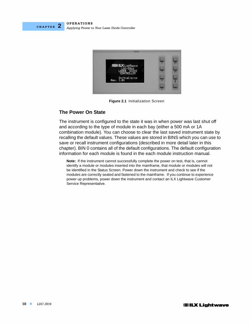
Figure 2.1 Initialization Screen . . . . . . . . . . . . . . . . . . . . . . . . . . . . . 10
Figure 2.2 Display Controls Screen . . . . . . . . . . . . . . . . . . . . . . . . . 11
Figure 2.3 Adjust Controls . . . . . . . . . . . . . . . . . . . . . . . . . . . . . . . . 12
Figure 2.4 Main Menu . . . . . . . . . . . . . . . . . . . . . . . . . . . . . . . . . . . . 14
Figure 2.5 Channel Menu . . . . . . . . . . . . . . . . . . . . . . . . . . . . . . . . . 15
Figure 2.6 System Configuration Menu . . . . . . . . . . . . . . . . . . . . . . 15
Figure 2.7 Communications Configuration Menu . . . . . . . . . . . . . . . 16
Figure 2.8 Display Configuration Menu . . . . . . . . . . . . . . . . . . . . . . 16
Figure 2.9 Calibration Menu . . . . . . . . . . . . . . . . . . . . . . . . . . . . . . . 18
Figure 2.10 Save and Recall Configuration Menu . . . . . . . . . . . . . . 18
Figure 2.11 All Channel Menu . . . . . . . . . . . . . . . . . . . . . . . . . . . . . 19
Figure 2.12 Setting All LAS menu . . . . . . . . . . . . . . . . . . . . . . . . . . 20
Figure 2.13 All TEC Menu page 1 . . . . . . . . . . . . . . . . . . . . . . . . . . 20
Figure 2.14 All TEC Menu page 2 . . . . . . . . . . . . . . . . . . . . . . . . . . 21
Figure 2.15 Status Menu . . . . . . . . . . . . . . . . . . . . . . . . . . . . . . . . . 21
Figure 2.16 Summary Screen . . . . . . . . . . . . . . . . . . . . . . . . . . . . . . 22
Figure 2.17 Status Screen page 2 . . . . . . . . . . . . . . . . . . . . . . . . . . 22
Figure 2.18 LDC-3916 Controller Modulation Input . . . . . . . . . . . . . 24

L I S T O F F I G U R E S
vi LDC-3916
Figure 3.1 GPIB Cable Connections . . . . . . . . . . . . . . . . . . . . . . . . 28
Figure 3.2 GPIB Connector Diagram . . . . . . . . . . . . . . . . . . . . . . . . 29
Figure 3.3 Command Path Structure . . . . . . . . . . . . . . . . . . . . . . . . 35
Figure 3.4 Status Reporting Schematic Diagram . . . . . . . . . . . . . . . 39

LDC-3916 vii
SAFETY AND WARRANTY INFORMATION
The Safety and Warranty Information section provides details about cautionary symbols used in the manual, safety markings used on the instrument, and information about the Warranty including Customer Service contact information.
Safety Information and the Manual
Throughout this manual, you will see the words Caution and Warning indicating potentially dangerous or hazardous situations which, if not avoided, could result in death, serious or minor injury, or damage to the product. Specifically:
! CAUTIONCaution indicates a potentially hazardous situation which can result in minor or moderate injury or damage to the product or equipment.
WARNING
Warning indicates a potentially dangerous situation which can result in serious injury or death.
WARNING
Visible and/or invisible laser radiation. Avoid direct exposure to the beam.
General Safety Considerations
If any of the following conditions exist, or are even suspected, do not use the instrument until safe operation can be verified by trained service personnel:
• Visible damage
• Severe transport stress
• Prolonged storage under adverse conditions
• Failure to perform intended measurements or functions
If necessary, return the instrument to ILX Lightwave, or authorized local ILX Lightwave distributor, for service or repair to ensure that safety features are maintained (see the contact information on page x).
All instruments returned to ILX Lightwave are required to have a Return Authorization Number assigned by an official representative of ILX Lightwave Corporation. See Returning an Instrument on page ix for more information.

S A F E T Y S Y M B O L S
viii LDC-3916
SAFETY SYMBOLS
This section describes the safety symbols and classifications.
Technical specifications including electrical ratings and weight are included within the manual. See the Table of Contents to locate the specifications and other product information. The following classifications are standard across all ILX Lightwave products:
• Indoor use only
• Ordinary Protection: This product is NOT protected against the harmful ingress of moisture.
• Class I Equipment (grounded type)
• Pollution Degree II
• Installation (overvoltage) Category II for transient overvoltages
• Maximum Relative Humidity: <80% RH, non-condensing
• Operating temperature range of 0 oC to 40 oC
• Storage and transportation temperature of -40 oC to 70 oC
• Maximum altitude: 3000 m (9843 ft)
• This equipment is suitable for continuous operation.
Safety Marking Symbols
This section provides a description of the safety marking symbols that appear on the instrument. These symbols provide information about potentially dangerous situations which can result in death, injury, or damage to the instrument and other components.
Caution, refer to manual
Earth ground Terminal
Alternating current
Visible and/or invisible laser radiation
Caution, risk of electric shock
Protective Conductor Terminal
Caution, hot surface
Frame or chassis Terminal
On: In position of a bistable push control. The slash (I) only denotes that mains are on.
Off: Out position of a bistable push control. The circle (O) only denotes that mains are off.or
(I)or(O)
WA R R A N T Y
LDC-3916 ix
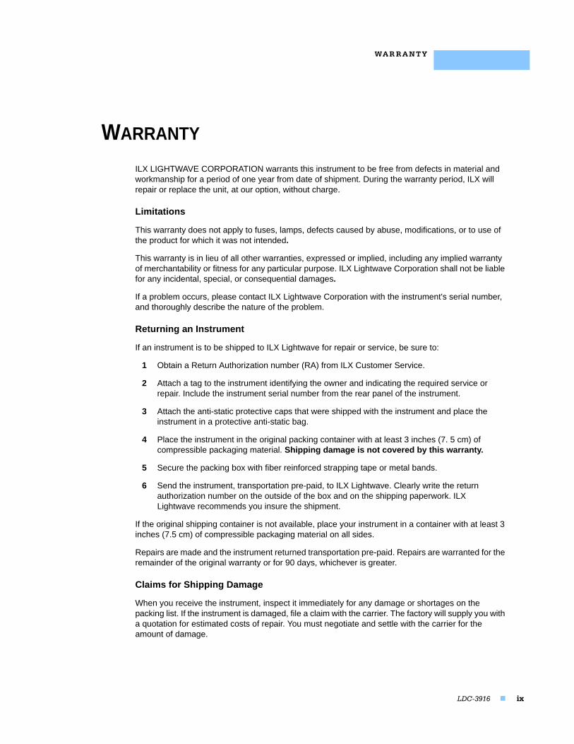
WARRANTY
ILX LIGHTWAVE CORPORATION warrants this instrument to be free from defects in material and workmanship for a period of one year from date of shipment. During the warranty period, ILX will repair or replace the unit, at our option, without charge.
Limitations
This warranty does not apply to fuses, lamps, defects caused by abuse, modifications, or to use of the product for which it was not intended.
This warranty is in lieu of all other warranties, expressed or implied, including any implied warranty of merchantability or fitness for any particular purpose. ILX Lightwave Corporation shall not be liable for any incidental, special, or consequential damages.
If a problem occurs, please contact ILX Lightwave Corporation with the instrument's serial number, and thoroughly describe the nature of the problem.
Returning an Instrument
If an instrument is to be shipped to ILX Lightwave for repair or service, be sure to:
1 Obtain a Return Authorization number (RA) from ILX Customer Service.
2 Attach a tag to the instrument identifying the owner and indicating the required service or repair. Include the instrument serial number from the rear panel of the instrument.
3 Attach the anti-static protective caps that were shipped with the instrument and place the instrument in a protective anti-static bag.
4 Place the instrument in the original packing container with at least 3 inches (7. 5 cm) of compressible packaging material. Shipping damage is not covered by this warranty.
5 Secure the packing box with fiber reinforced strapping tape or metal bands.
6 Send the instrument, transportation pre-paid, to ILX Lightwave. Clearly write the return authorization number on the outside of the box and on the shipping paperwork. ILX Lightwave recommends you insure the shipment.
If the original shipping container is not available, place your instrument in a container with at least 3 inches (7.5 cm) of compressible packaging material on all sides.
Repairs are made and the instrument returned transportation pre-paid. Repairs are warranted for the remainder of the original warranty or for 90 days, whichever is greater.
Claims for Shipping Damage
When you receive the instrument, inspect it immediately for any damage or shortages on the packing list. If the instrument is damaged, file a claim with the carrier. The factory will supply you with a quotation for estimated costs of repair. You must negotiate and settle with the carrier for the amount of damage.

WA R R A N T Y
x LDC-3916
Comments, Suggestions, and Problems
To ensure that you get the most out of your ILX Lightwave product, we ask that you direct any product operation or service related questions or comments to ILX Lightwave Customer Support. You may contact us in whatever way is most convenient.
In the United States:
Phone . . . . . . . . . . . . . . . . . . . . . . . . . . . (800) 459-9459 or (406) 586-1244
Fax . . . . . . . . . . . . . . . . . . . . . . . . . . . . . . . . . . . . . . . . . . . . . (406) 586-9405
Online: . . . . . . . . . . . . . . . . . . . . . . . . . . . . . . . . . . . . . http://ilx.custhelp.com
Email: . . . . . . . . . . . . . . . . . . . . . . . . . . . . . . . . . . . [email protected]
Or mail to:
ILX Lightwave CorporationP. O. Box 6310Bozeman, Montana, U.S.A 59771www.ilxlightwave.com
In Europe: In Japan:Optical Test and Calibration Ltd.Listerhills Science ParkBradford, BD7 1HR United KingdomPhone: (44) 1274 393857Fax: (44) 1274 393336Online: www.otc.co.ukEmail: [email protected]
Kyosai Technos424, Shimo-Ongata-MachiHachioji-ShiTokyo, 192-0154 JapanPhone: (81) 426 521 388Fax: (81) 426 513 270
In China: In China:ETSC Technologies Co.9/F Building 1SBI StreetDongxin RoadEast Lake High-Tech Development ZoneWuhan, Hubei, 430074 PRC ChinaPhone: (86) 27 8717 0152; (86) 27 8741 2681; (86) 27 8780 7925Fax: (86) 27 8780 7133Online: www.etsc-tech.comEmail: [email protected]
Kyosai Technos3F Bldg G, No.21 Changjiang Road, WuxiNational Hi-Tech Development ZoneJiangsu, P.R. ChinaPhone: (86) 510 522 1707Fax: (86) 510 522 1679Email: [email protected]
WA R R A N T Y
LDC-3916 xi
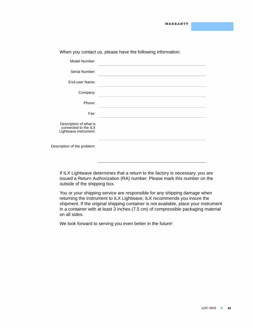
When you contact us, please have the following information:
If ILX Lightwave determines that a return to the factory is necessary, you are issued a Return Authorization (RA) number. Please mark this number on the outside of the shipping box.
You or your shipping service are responsible for any shipping damage when returning the instrument to ILX Lightwave; ILX recommends you insure the shipment. If the original shipping container is not available, place your instrument in a container with at least 3 inches (7.5 cm) of compressible packaging material on all sides.
We look forward to serving you even better in the future!
Model Number:
Serial Number:
End-user Name:
Company:
Phone:
Fax:
Description of what isconnected to the ILX
Lightwave instrument:
Description of the problem:

WA R R A N T Y
xii LDC-3916
LDC-3916 1
C H A P T E R 1
INTRODUCTION
This chapter is an introduction to the LDC-3916 Laser Diode Controller. It contains unpacking information, instructions on how to install and apply power, and safety considerations. It also contains some maintenance information, specifications, and a list of options and accessories.
Product Overview
The LDC-3916 Multi-Channel Laser Diode Controller accepts up to 16 channels of laser diode current source and temperature control modules in a space-saving rack-mountable instrument. On-board microprocessors in each module receive control data from the 3916 mainframe and handle control, measurement and laser protection functions. Sixteen independent, isolated linear power supplies power each module, providing per channel laser diode protection, low noise and high current stability. A wide variety of modules are available including laser controller modules, dual channel laser current source, and dual channel temperature control modules. Controller modules source up to 1.5A of laser current with an integrated 9W temperature controller. Dual laser current source modules, with two isolated outputs, source up to 1A per channel, while dual temperature control modules provide two independent 9W outputs for control of up to 32 laser diodes per mainframe. Remote operation for independent control of all sixteen channels is provided through in IEEE-488 GPIB interface or RS-232 serial interface.
Detailed operation information for any of the control modules is provided in their respective operation manual.
I N T R O D U C T I O NProduct Overview
2 LDC-3916
C H A P T E R 1
Initial Inspection
When you receive your LDC-3916 Controller, verify that the following items were shipped with the instrument:
• LDC-3916 Laser Diode Controller
• LDC-3916 Mainframe Instruction Manual
• Power Cord
Note: When unpacking the instrument, be sure to save the packaging and the protective ESD caps on the rear of the instrument in case you have to return the instrument to ILX Lightwave or ship it elsewhere. Shipping damage is not covered under the standard instrument warranty.
I N T R O D U C T I O NInstalling the LDC-3916 Laser Diode Controller
07_15 LDC-3916 3
C H A P T E R 1
Installing the LDC-3916 Laser Diode Controller
This section provides information about the necessary requirements to install the LDC-3916 and how to begin operating the instrument.
Grounding Requirements
The LDC-3916 Laser Diode Controller comes with a three-conductor AC power cable. The power cable must either be plugged into an approved three-contact electrical outlet or used with a three-contact to two-contact adaptor with the grounding wire connected to an electrical ground (safety ground). The LDC-3916's power jack and supplied power cable meet IEC safety standards.
AC Line Power Requirements
You can operate the LDC-3916 Controller from a single-phase power source delivering nominal line voltages of 110 - 130 VAC at 60 Hz or 210 - 240 VAC at 50 or 60 Hz. The line power voltage can vary + 10%. Maximum power consumption is 1440 Volt-Amps with 16 modules (LDC-3916376 1.5A/9W Controller modules). The instrument's operational voltage is factory configurable and need not be changed before operating the instrument.
Before connecting the LDC-3916 to an AC power source, verify that the power source matches the voltage setting printed on the power entry module.
To avoid electrical shock hazard, connect the instrument only to properly earth-grounded, three-prong receptacles. Failure to observe this precaution can result in severe injury or death.
RS-232 Connectors
The RS-232 interface consists of two 9-pin, D-sub connectors, located on the rear panel. The A connector is used to connect to the host computer with a standard straight-through cable (see Figure 1.2 on page 6). The B connector is not enabled at this time.
GPIB Connector
The GPIB interface connector is located on the rear panel, directly to the left of the power input module. See Figure 1.2 on page 6. Attach the GPIB cable to the 24-pin interface connector, which is tapered to ensure proper orientation. Finger tighten the two screws on the cable connector.
I N T R O D U C T I O NInstalling the LDC-3916 Laser Diode Controller
4 LDC-3916
C H A P T E R 1
A total of 15 devices can be connected together on the same GPIB interface bus. The cables have single male/female connectors on each end so that several cables can be stacked. This permits more than one cable to be attached to any one device. However, the maximum length of the GPIB cables must not exceed 20 meters (65 feet) total, or 2 meters (6.5 feet) per device.
The GPIB Address
The talk and listen addresses on the LDC-3916 Laser Diode Controller are identical. The controller comes from the factory configured with the GPIB address set to 1. You can change the LDC-3916's GPIB address locally (via the front panel). A procedure for changing the address can be found in Changing the GPIB Address on page 27.
Tilt-Foot Adjustment
The LDC-3916 Laser Diode Controller comes standard with folding front legs and two rear feet for use as a benchtop instrument. The front panel vacuum Fluorescent display may be easier to read if you extend the front legs so that the instrument front panel tilts upward. Simply place the unit on a stable base and rotate the front legs downward until they lock into position.
Rack Mounting
The LDC-3916 can be mounted in a standard 19-inch rack with two available Rack Mounting Kits. These kits contain instrument support brackets which fasten to the inside of your rack enclosure to support your LDC-3916 along each side at the bottom of the instrument. There are two kits available as mentioned above. Kit number RM-137 is for rack enclosures 24 inches in depth. RM-138 is for rack enclosures 30 or 36 inches in depth. Each kit comes with the necessary hardware, including fasteners and instructions for their use.
I N T R O D U C T I O NInstalling the LDC-3916 Laser Diode Controller
07_15 LDC-3916 5
C H A P T E R 1
LDC-3916 Orientation
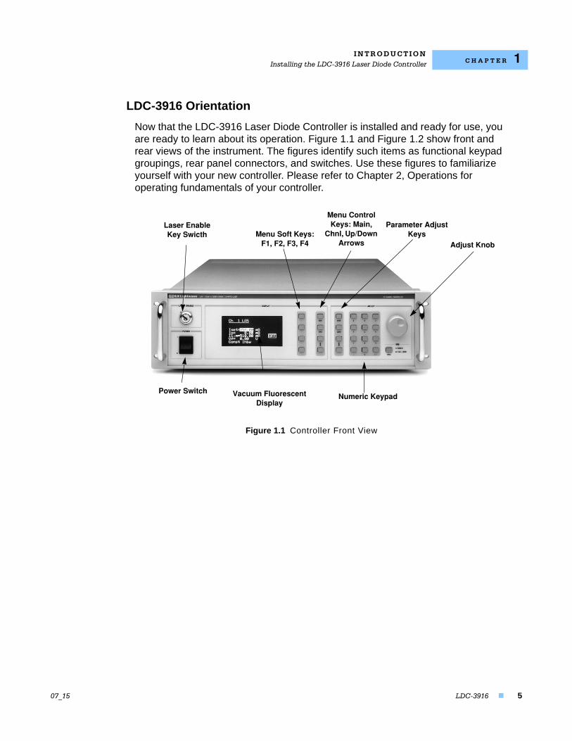
Now that the LDC-3916 Laser Diode Controller is installed and ready for use, you are ready to learn about its operation. Figure 1.1 and Figure 1.2 show front and rear views of the instrument. The figures identify such items as functional keypad groupings, rear panel connectors, and switches. Use these figures to familiarize yourself with your new controller. Please refer to Chapter 2, Operations for operating fundamentals of your controller.
Figure 1.1 Controller Front View
Laser Enable Key Swicth
Parameter Adjust Keys
Menu Control Keys: Main,
Chnl, Up/Down Arrows Adjust Knob
Power Switch
Menu Soft Keys: F1, F2, F3, F4
Numeric KeypadVacuum Fluorescent Display
I N T R O D U C T I O NInstalling the LDC-3916 Laser Diode Controller
6 LDC-3916
C H A P T E R 1
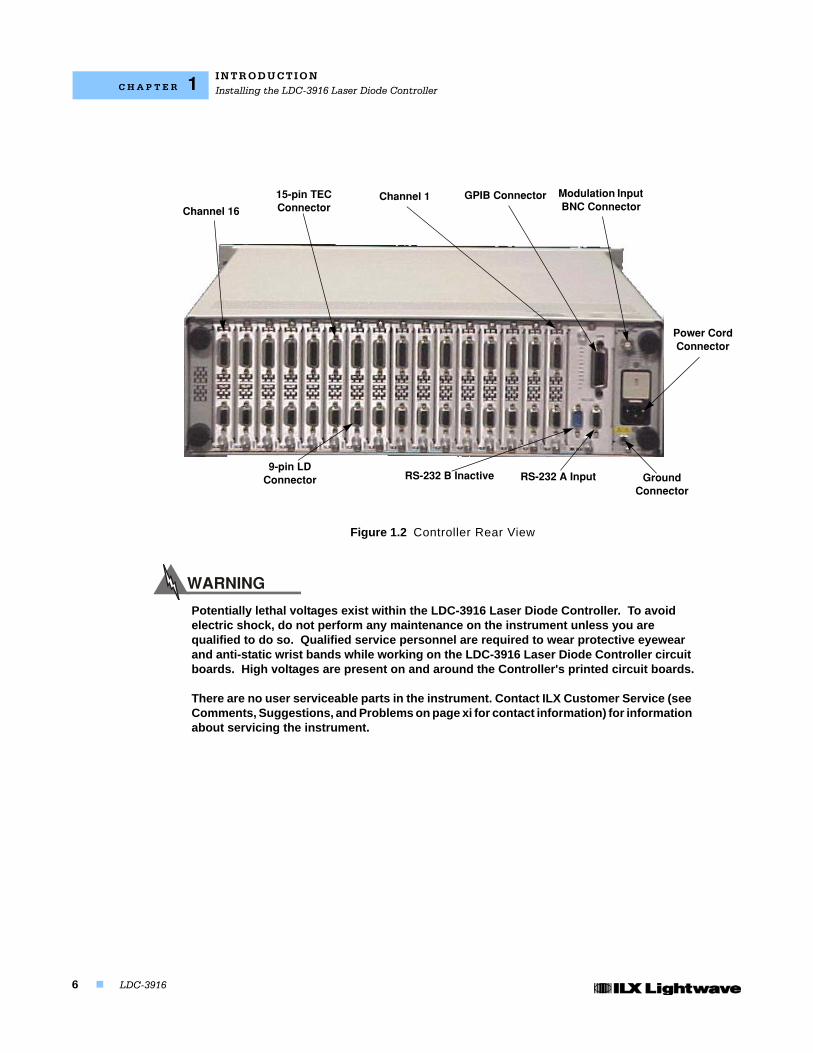
Figure 1.2 Controller Rear View
Potentially lethal voltages exist within the LDC-3916 Laser Diode Controller. To avoid electric shock, do not perform any maintenance on the instrument unless you are qualified to do so. Qualified service personnel are required to wear protective eyewear and anti-static wrist bands while working on the LDC-3916 Laser Diode Controller circuit boards. High voltages are present on and around the Controller's printed circuit boards.
There are no user serviceable parts in the instrument. Contact ILX Customer Service (see Comments, Suggestions, and Problems on page xi for contact information) for information about servicing the instrument.
Channel 16
15−pin TEC Connector
Channel 1 Modulation Input BNC Connector
Power Cord Connector
Ground Connector
RS−232 A InputRS−232 B Inactive9−pin LD
Connector
GPIB Connector
I N T R O D U C T I O NSpecifications
07_15 LDC-3916 7
C H A P T E R 1
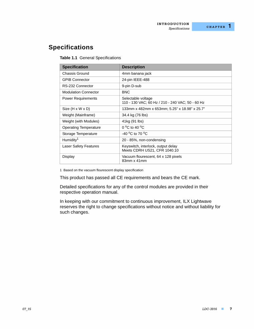
Specifications
1 Based on the vacuum flourescent display specification
This product has passed all CE requirements and bears the CE mark.
Detailed specifications for any of the control modules are provided in their respective operation manual.
In keeping with our commitment to continuous improvement, ILX Lightwave reserves the right to change specifications without notice and without liability for such changes.
Table 1.1 General Specifications
Specification Description
Chassis Ground 4mm banana jack
GPIB Connector 24-pin IEEE-488
RS-232 Connector 9-pin D-sub
Modulation Connector BNC
Power Requirements Selectable voltage110 - 130 VAC; 60 Hz / 210 - 240 VAC; 50 - 60 Hz
Size (H x W x D) 133mm x 482mm x 653mm; 5.25” x 18.98” x 25.7”
Weight (Mainframe) 34.4 kg (76 lbs)
Weight (with Modules) 41kg (91 lbs)
Operating Temperature 0 oC to 40 oC
Storage Temperature -40 oC to 70 oC
Humidity1 20 - 85%, non-condensing
Laser Safety Features Keyswitch, interlock, output delayMeets CDRH US21, CFR 1040.10
Display Vacuum flourescent, 64 x 128 pixels83mm x 41mm
I N T R O D U C T I O NSpecifications
8 LDC-3916
C H A P T E R 1
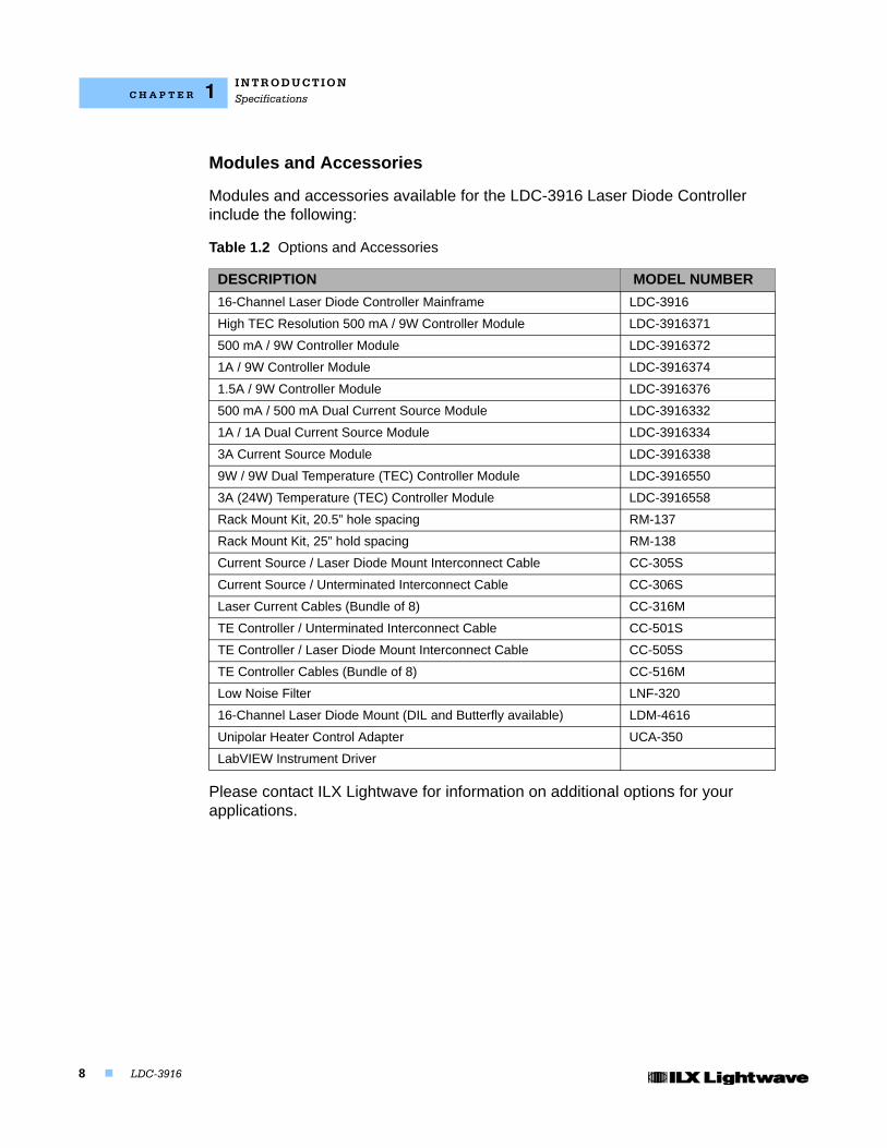
Modules and Accessories
Modules and accessories available for the LDC-3916 Laser Diode Controller include the following:
Please contact ILX Lightwave for information on additional options for your applications.
Table 1.2 Options and Accessories
DESCRIPTION MODEL NUMBER
16-Channel Laser Diode Controller Mainframe LDC-3916
High TEC Resolution 500 mA / 9W Controller Module LDC-3916371
500 mA / 9W Controller Module LDC-3916372
1A / 9W Controller Module LDC-3916374
1.5A / 9W Controller Module LDC-3916376
500 mA / 500 mA Dual Current Source Module LDC-3916332
1A / 1A Dual Current Source Module LDC-3916334
3A Current Source Module LDC-3916338
9W / 9W Dual Temperature (TEC) Controller Module LDC-3916550
3A (24W) Temperature (TEC) Controller Module LDC-3916558
Rack Mount Kit, 20.5” hole spacing RM-137
Rack Mount Kit, 25” hold spacing RM-138
Current Source / Laser Diode Mount Interconnect Cable CC-305S
Current Source / Unterminated Interconnect Cable CC-306S
Laser Current Cables (Bundle of 8) CC-316M
TE Controller / Unterminated Interconnect Cable CC-501S
TE Controller / Laser Diode Mount Interconnect Cable CC-505S
TE Controller Cables (Bundle of 8) CC-516M
Low Noise Filter LNF-320
16-Channel Laser Diode Mount (DIL and Butterfly available) LDM-4616
Unipolar Heater Control Adapter UCA-350
LabVIEW Instrument Driver
LDC-3916 9
C H A P T E R 2
OPERATIONS
This chapter introduces you to the operation of the LDC-3916 sixteen-channel laser diode controller. It offers instructions for connecting your laser to the current source and temperature controller modules and describes powering up the instrument. The chapter also provides a description of the front panel controls, including both display and adjust controls.
The bulk of the chapter provides a description of the LDC-3916 Menu Structure. This section provides pictures of the display screen associated with each menu for the LDC-3916 Mainframe related to general operation of the instrument. This section also provides instructions on how to select each menu and how to perform the operations relevant to the menu selected.
Applying Power to Your Laser Diode Controller
To turn on the LDC-3916, push the button in the Power section of the front panel to change the setting from zero (0) to one (1). This action will initiate the Power-on sequence. If the LDC-3916 does not appear to turn on, verify that it is connected to line power. If line power is not the problem, remove the power cord and check the line power fuse.
The Power On Sequence
When power is applied to the LDC-3916, the following takes place: for about six seconds the initialization screen is displayed, showing the company name and logo, the name of instrument, and firmware version (in the lower left-hand corner of the screen). During this time, a self test is performed to ensure that the mainframe processor is communicating with the processor(s) of any module(s) connected to the mainframe and identifying which module model is present. After this test, the instrument is ready to operate and is configured to the state it was in when the power was last shut off.
O P E R A T I O N SApplying Power to Your Laser Diode Controller
10 LDC-3916
C H A P T E R 2
Figure 2.1 Initialization Screen
The Power On State
The instrument is configured to the state it was in when power was last shut off and according to the type of module in each bay (either a 500 mA or 1A combination module). You can choose to clear the last saved instrument state by recalling the default values. These values are stored in BINS which you can use to save or recall instrument configurations (described in more detail later in this chapter). BIN 0 contains all of the default configurations. The default configuration information for each module is found in the each module instruction manual.
Note: If the instrument cannot successfully complete the power on test, that is, cannot identify a module or modules inserted into the mainframe, that module or modules will not be identified in the Status Screen. Power down the instrument and check to see if the modules are correctly seated and fastened to the mainframe. If you continue to experience power up problems, power down the instrument and contact an ILX Lightwave Customer Service Representative.
O P E R A T I O N SLDC-3916 Front Panel Controls
07_15 LDC-3916 11
C H A P T E R 2
LDC-3916 Front Panel Controls
All key operating parameters for the LAS (laser) and TEC modules can be set, adjusted, and displayed through established menus. (See the respective module manual for further information on each module.)
Display Controls
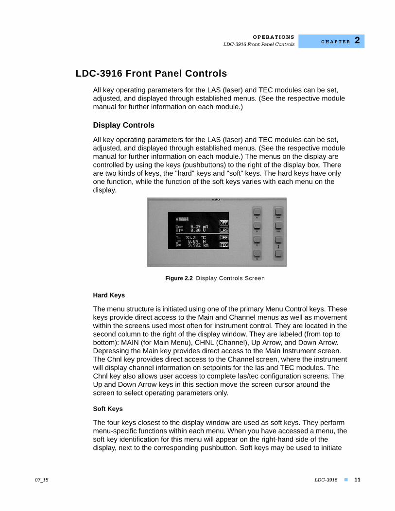
All key operating parameters for the LAS (laser) and TEC modules can be set, adjusted, and displayed through established menus. (See the respective module manual for further information on each module.) The menus on the display are controlled by using the keys (pushbuttons) to the right of the display box. There are two kinds of keys, the "hard" keys and "soft" keys. The hard keys have only one function, while the function of the soft keys varies with each menu on the display.
Figure 2.2 Display Controls Screen
Hard Keys
The menu structure is initiated using one of the primary Menu Control keys. These keys provide direct access to the Main and Channel menus as well as movement within the screens used most often for instrument control. They are located in the second column to the right of the display window. They are labeled (from top to bottom): MAIN (for Main Menu), CHNL (Channel), Up Arrow, and Down Arrow. Depressing the Main key provides direct access to the Main Instrument screen. The Chnl key provides direct access to the Channel screen, where the instrument will display channel information on setpoints for the las and TEC modules. The Chnl key also allows user access to complete las/tec configuration screens. The Up and Down Arrow keys in this section move the screen cursor around the screen to select operating parameters only.
Soft Keys
The four keys closest to the display window are used as soft keys. They perform menu-specific functions within each menu. When you have accessed a menu, the soft key identification for this menu will appear on the right-hand side of the display, next to the corresponding pushbutton. Soft keys may be used to initiate
O P E R A T I O N SLDC-3916 Front Panel Controls
12 LDC-3916
C H A P T E R 2
another menu or to change/edit a parameter. For example, in the LAS section of the Chnl menu, the word "On" designates the state of the output. Depressing the associated soft key will change the state from On to Off. If the LAS soft key is depressed, the laser setup menu will be displayed. (Full descriptions of each menu are provided later in this chapter.)
Adjust Controls
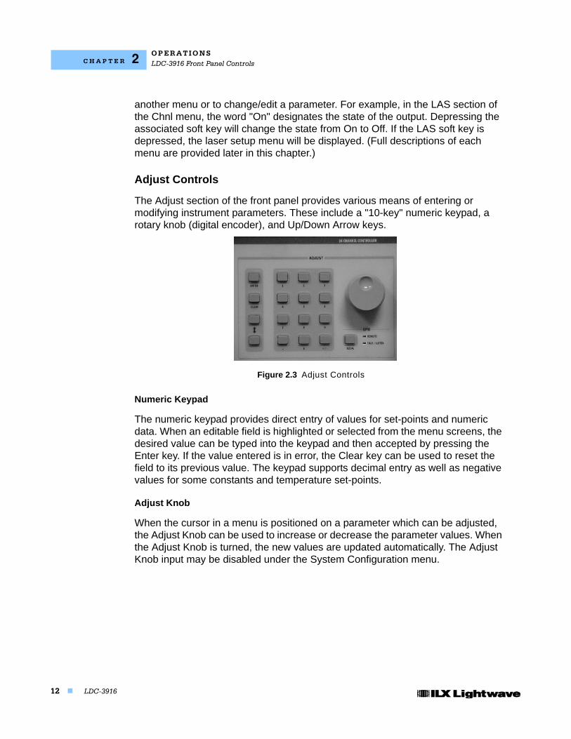
The Adjust section of the front panel provides various means of entering or modifying instrument parameters. These include a "10-key" numeric keypad, a rotary knob (digital encoder), and Up/Down Arrow keys.
Figure 2.3 Adjust Controls
Numeric Keypad
The numeric keypad provides direct entry of values for set-points and numeric data. When an editable field is highlighted or selected from the menu screens, the desired value can be typed into the keypad and then accepted by pressing the Enter key. If the value entered is in error, the Clear key can be used to reset the field to its previous value. The keypad supports decimal entry as well as negative values for some constants and temperature set-points.
Adjust Knob
When the cursor in a menu is positioned on a parameter which can be adjusted, the Adjust Knob can be used to increase or decrease the parameter values. When the Adjust Knob is turned, the new values are updated automatically. The Adjust Knob input may be disabled under the System Configuration menu.
O P E R A T I O N SLDC-3916 Front Panel Controls
07_15 LDC-3916 13
C H A P T E R 2
Arrow Keys
The two Adjust Up/Down Arrow keys also can be used to adjust values on any of the screens where a numeric value is required. Holding down either of the keys will increase or decrease the number via a simple time-based acceleration algorithm. When the Arrow keys are pressed, the new values are updated automatically.
O P E R A T I O N SUsing the LDC-3916 Menu Structure
14 LDC-3916
C H A P T E R 2
Using the LDC-3916 Menu Structure
This section describes the menus, how they are structured, and how to navigate through them.
Main Menu
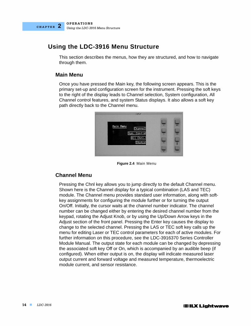
Once you have pressed the Main key, the following screen appears. This is the primary set-up and configuration screen for the instrument. Pressing the soft keys to the right of the display leads to Channel selection, System configuration, All Channel control features, and system Status displays. It also allows a soft key path directly back to the Channel menu.
Figure 2.4 Main Menu
Channel Menu
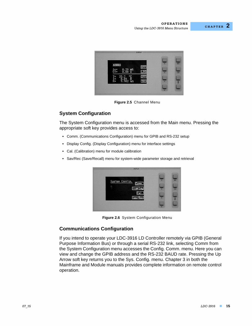
Pressing the Chnl key allows you to jump directly to the default Channel menu. Shown here is the Channel display for a typical combination (LAS and TEC) module. The Channel menu provides standard user information, along with soft-key assignments for configuring the module further or for turning the output On/Off. Initially, the cursor waits at the channel number indicator. The channel number can be changed either by entering the desired channel number from the keypad, rotating the Adjust Knob, or by using the Up/Down Arrow keys in the Adjust section of the front panel. Pressing the Enter key causes the display to change to the selected channel. Pressing the LAS or TEC soft key calls up the menu for editing Laser or TEC control parameters for each of active modules. For further information on this procedure, see the LDC-3916370 Series Controller Module Manual. The output state for each module can be changed by depressing the associated soft key Off or On, which is accompanied by an audible beep (if configured). When either output is on, the display will indicate measured laser output current and forward voltage and measured temperature, thermoelectric module current, and sensor resistance.
O P E R A T I O N SUsing the LDC-3916 Menu Structure
07_15 LDC-3916 15
C H A P T E R 2
Figure 2.5 Channel Menu
System Configuration
The System Configuration menu is accessed from the Main menu. Pressing the appropriate soft key provides access to:
• Comm. (Communications Configuration) menu for GPIB and RS-232 setup
• Display Config. (Display Configuration) menu for interface settings
• Cal. (Calibration) menu for module calibration
• Sav/Rec (Save/Recall) menu for system-wide parameter storage and retrieval
Figure 2.6 System Configuration Menu
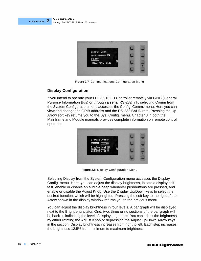
Communications Configuration
If you intend to operate your LDC-3916 LD Controller remotely via GPIB (General Purpose Information Bus) or through a serial RS-232 link, selecting Comm from the System Configuration menu accesses the Config. Comm. menu. Here you can view and change the GPIB address and the RS-232 BAUD rate. Pressing the Up Arrow soft key returns you to the Sys. Config. menu. Chapter 3 in both the Mainframe and Module manuals provides complete information on remote control operation.
O P E R A T I O N SUsing the LDC-3916 Menu Structure
16 LDC-3916
C H A P T E R 2
Figure 2.7 Communications Configuration Menu
Display Configuration
If you intend to operate your LDC-3916 LD Controller remotely via GPIB (General Purpose Information Bus) or through a serial RS-232 link, selecting Comm from the System Configuration menu accesses the Config. Comm. menu. Here you can view and change the GPIB address and the RS-232 BAUD rate. Pressing the Up Arrow soft key returns you to the Sys. Config. menu. Chapter 3 in both the Mainframe and Module manuals provides complete information on remote control operation.
Figure 2.8 Display Configuration Menu
Selecting Display from the System Configuration menu accesses the Display Config. menu. Here, you can adjust the display brightness, initiate a display self-test, enable or disable an audible beep whenever pushbuttons are pressed, and enable or disable the Adjust Knob. Use the Display Up/Down keys to select the desired function, which will be highlighted. Pressing the soft key to the right of the Arrow shown in the display window returns you to the previous menu.
You can adjust the display brightness in four levels. A bar graph will be displayed next to the Bright enunciator. One, two, three or no sections of the bar graph will be back lit, indicating the level of display brightness. You can adjust the brightness by either rotating the Adjust Knob or depressing the Adjust Up/Down Arrow keys in the section. Display brightness increases from right to left. Each step increases the brightness 12.5% from minimum to maximum brightness.
O P E R A T I O N SUsing the LDC-3916 Menu Structure
07_15 LDC-3916 17
C H A P T E R 2
If there is a problem with the graphic display, a display self-test can be initiated from this menu. After selecting the Display Test function using the hard keys, use either the Adjust Knob or the Adjust Up/Down Arrow keys to display the word, "Yes". Press Adjust Enter in the section to activate the test. The display will be instructed to light up all pixels. You can perform a visual inspection of the display to ensure that all of the pixels are illuminated. You should see a rectangular grid. If you find a display problem, contact the Customer Service Department of ILX Lightwave (See Comments, Suggestions, and Problems on page xi., for more information.). Pressing the Main or Chnl keys will return you to those specific menus. Pressing any other key returns you to the previous menu.
The Audible beep function allows you to enable or disable an audible "beep" tone heard when any key (either hard key or soft key) is pressed. The On or Off enunciator (depending on the current state of this function) will be highlighted when selected. Use the Adjust Knob or Adjust Up/Down Arrow keys to change from off to on or on to off. You must press Adjust Enter after making the desired selection to execute the change.
The Adjust Knob also can be enabled or disabled from this menu. Once the Lockout dial function is selected, the On or Off enunciator will be highlighted (depending on the current state of this function). Use the Adjust Knob or Adjust Up/Down Arrow keys to change from off to on or on to off. Press Adjust Enter after making the desired selection to execute the change.
Calibration
The Calibration Menu allows you to calibrate from the front panel all Laser and TEC functions for each of the modules (16 max.) you have loaded in the LDC-3916 Mainframe. Remote calibration through the IEEE488.2 GPIB or serial RS-232 interface is provided as well. (See Chapter 3.) ILX Lightwave recommends that the instrument be calibrated every 12 months, or whenever performance verification indicates that calibration is necessary (such as any difference between the displayed Laser current and the actual laser current which exceeds the specified value). Calibrate the instrument under laboratory conditions. We recommend calibration at 23 oC ± 1.0 oC. When necessary, however, the LDC-3916 Laser Diode Controller may be calibrated at its intended use temperature (if this is within the specified operating temperature range of 0 oC to 40 oC).
O P E R A T I O N SUsing the LDC-3916 Menu Structure
18 LDC-3916
C H A P T E R 2
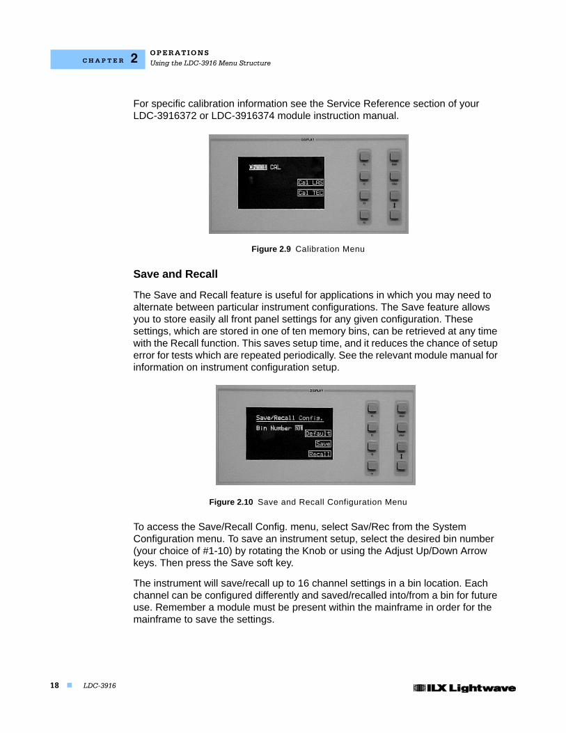
For specific calibration information see the Service Reference section of your LDC-3916372 or LDC-3916374 module instruction manual.
Figure 2.9 Calibration Menu
Save and Recall
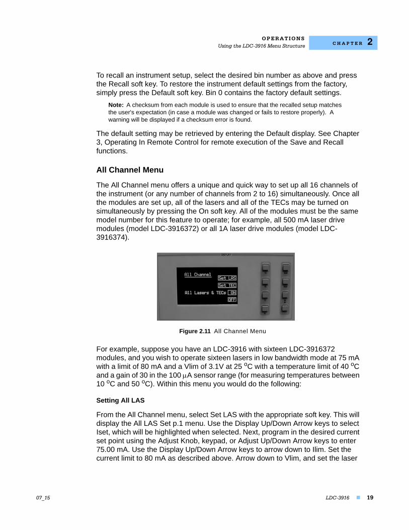
The Save and Recall feature is useful for applications in which you may need to alternate between particular instrument configurations. The Save feature allows you to store easily all front panel settings for any given configuration. These settings, which are stored in one of ten memory bins, can be retrieved at any time with the Recall function. This saves setup time, and it reduces the chance of setup error for tests which are repeated periodically. See the relevant module manual for information on instrument configuration setup.
Figure 2.10 Save and Recall Configuration Menu
To access the Save/Recall Config. menu, select Sav/Rec from the System Configuration menu. To save an instrument setup, select the desired bin number (your choice of #1-10) by rotating the Knob or using the Adjust Up/Down Arrow keys. Then press the Save soft key.
The instrument will save/recall up to 16 channel settings in a bin location. Each channel can be configured differently and saved/recalled into/from a bin for future use. Remember a module must be present within the mainframe in order for the mainframe to save the settings.
O P E R A T I O N SUsing the LDC-3916 Menu Structure
07_15 LDC-3916 19
C H A P T E R 2
To recall an instrument setup, select the desired bin number as above and press the Recall soft key. To restore the instrument default settings from the factory, simply press the Default soft key. Bin 0 contains the factory default settings.
Note: A checksum from each module is used to ensure that the recalled setup matches the user's expectation (in case a module was changed or fails to restore properly). A warning will be displayed if a checksum error is found.
The default setting may be retrieved by entering the Default display. See Chapter 3, Operating In Remote Control for remote execution of the Save and Recall functions.
All Channel Menu
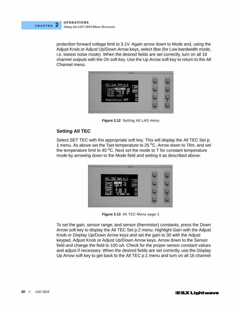
The All Channel menu offers a unique and quick way to set up all 16 channels of the instrument (or any number of channels from 2 to 16) simultaneously. Once all the modules are set up, all of the lasers and all of the TECs may be turned on simultaneously by pressing the On soft key. All of the modules must be the same model number for this feature to operate; for example, all 500 mA laser drive modules (model LDC-3916372) or all 1A laser drive modules (model LDC-3916374).
Figure 2.11 All Channel Menu
For example, suppose you have an LDC-3916 with sixteen LDC-3916372 modules, and you wish to operate sixteen lasers in low bandwidth mode at 75 mA with a limit of 80 mA and a Vlim of 3.1V at 25 oC with a temperature limit of 40 oC and a gain of 30 in the 100 A sensor range (for measuring temperatures between 10 oC and 50 oC). Within this menu you would do the following:
Setting All LAS
From the All Channel menu, select Set LAS with the appropriate soft key. This will display the All LAS Set p.1 menu. Use the Display Up/Down Arrow keys to select Iset, which will be highlighted when selected. Next, program in the desired current set point using the Adjust Knob, keypad, or Adjust Up/Down Arrow keys to enter 75.00 mA. Use the Display Up/Down Arrow keys to arrow down to Ilim. Set the current limit to 80 mA as described above. Arrow down to Vlim, and set the laser
O P E R A T I O N SUsing the LDC-3916 Menu Structure
20 LDC-3916
C H A P T E R 2
protection forward voltage limit to 3.1V. Again arrow down to Mode and, using the Adjust Knob or Adjust Up/Down Arrow keys, select Ilbw (for Low bandwidth mode, i.e. lowest noise mode). When the desired fields are set correctly, turn on all 16 channel outputs with the On soft key. Use the Up Arrow soft key to return to the All Channel menu.
Figure 2.12 Setting All LAS menu
Setting All TEC
Select SET TEC with the appropriate soft key. This will display the All TEC Set p. 1 menu. As above set the Tset temperature to 25 oC. Arrow down to Tlim, and set the temperature limit to 40 oC. Next set the mode to T for constant temperature mode by arrowing down to the Mode field and setting it as described above.
Figure 2.13 All TEC Menu page 1
To set the gain, sensor range, and sensor (thermistor) constants, press the Down Arrow soft key to display the All TEC Set p.2 menu. Highlight Gain with the Adjust Knob or Display Up/Down Arrow keys and set the gain to 30 with the Adjust keypad, Adjust Knob or Adjust Up/Down Arrow keys. Arrow down to the Sensor field and change the field to 100 uA. Check for the proper sensor constant values and adjust if necessary. When the desired fields are set correctly, use the Display Up Arrow soft key to get back to the All TEC p.1 menu and turn on all 16 channel
O P E R A T I O N SUsing the LDC-3916 Menu Structure
07_15 LDC-3916 21
C H A P T E R 2
outputs with the On soft key. Now all channels are controlling the temperature of your laser to 25 oC.
Figure 2.14 All TEC Menu page 2
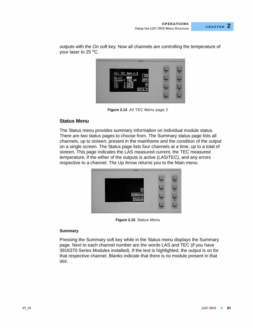
Status Menu
The Status menu provides summary information on individual module status. There are two status pages to choose from. The Summary status page lists all channels, up to sixteen, present in the mainframe and the condition of the output on a single screen. The Status page lists four channels at a time, up to a total of sixteen. This page indicates the LAS measured current, the TEC measured temperature, if the either of the outputs is active (LAS/TEC), and any errors respective to a channel. The Up Arrow returns you to the Main menu.
Figure 2.15 Status Menu
Summary
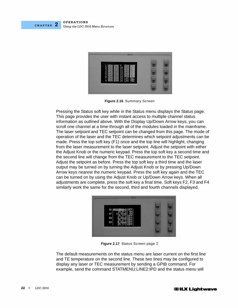
Pressing the Summary soft key while in the Status menu displays the Summary page. Next to each channel number are the words LAS and TEC (if you have 3916370 Series Modules installed). If the text is highlighted, the output is on for that respective channel. Blanks indicate that there is no module present in that slot.
O P E R A T I O N SUsing the LDC-3916 Menu Structure
22 LDC-3916
C H A P T E R 2
Figure 2.16 Summary Screen
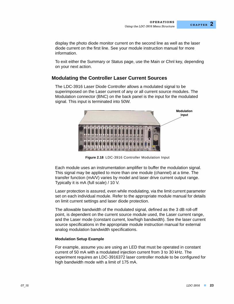
Pressing the Status soft key while in the Status menu displays the Status page. This page provides the user with instant access to multiple channel status information as outlined above. With the Display Up/Down Arrow keys, you can scroll one channel at a time through all of the modules loaded in the mainframe. The laser setpoint and TEC setpoint can be changed from this page. The mode of operation of the laser and the TEC determines which setpoint adjustments can be made. Press the top soft key (F1) once and the top line will highlight, changing from the laser measurement to the laser setpoint. Adjust the setpoint with either the Adjust Knob or the numeric keypad. Press the top soft key a second time and the second line will change from the TEC measurement to the TEC setpoint. Adjust the setpoint as before. Press the top soft key a third time and the laser output may be turned on by turning the Adjust Knob or by pressing Up/Down Arrow keys nearest the numeric keypad. Press the soft key again and the TEC can be turned on by using the Adjust Knob or Up/Down Arrow keys. When all adjustments are complete, press the soft key a final time. Soft keys F2, F3 and F4 similarly work the same for the second, third and fourth channels displayed.
Figure 2.17 Status Screen page 2
The default measurements on the status menu are laser current on the first line and TE temperature on the second line. These two lines may be configured to display any laser or TEC measurement by sending a GPIB command. For example, send the command STATMENU:LINE2:IPD and the status menu will
O P E R A T I O N SUsing the LDC-3916 Menu Structure
07_15 LDC-3916 23
C H A P T E R 2
display the photo diode monitor current on the second line as well as the laser diode current on the first line. See your module instruction manual for more information.
To exit either the Summary or Status page, use the Main or Chnl key, depending on your next action.
Modulating the Controller Laser Current Sources
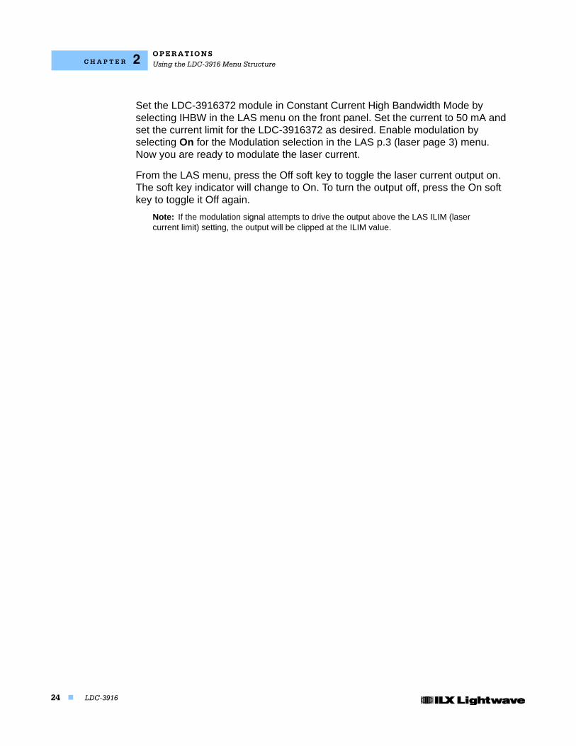
The LDC-3916 Laser Diode Controller allows a modulated signal to be superimposed on the Laser current of any or all current source modules. The Modulation connector (BNC) on the back panel is the input for the modulated signal. This input is terminated into 50W.
Figure 2.18 LDC-3916 Controller Modulation Input
Each module uses an instrumentation amplifier to buffer the modulation signal. This signal may be applied to more than one module (channel) at a time. The transfer function (mA/V) varies by model and laser drive current output range. Typically it is mA (full scale) / 10 V.
Laser protection is assured, even while modulating, via the limit current parameter set on each individual module. Refer to the appropriate module manual for details on limit current settings and laser diode protection.
The allowable bandwidth of the modulated signal, defined as the 3 dB roll-off point, is dependent on the current source module used, the Laser current range, and the Laser mode (constant current, low/high bandwidth). See the laser current source specifications in the appropriate module instruction manual for external analog modulation bandwidth specifications.
Modulation Setup Example
For example, assume you are using an LED that must be operated in constant current of 50 mA with a modulated injection current from 3 to 30 kHz. The experiment requires an LDC-3916372 laser controller module to be configured for high bandwidth mode with a limit of 175 mA.
Modulation input
O P E R A T I O N SUsing the LDC-3916 Menu Structure
24 LDC-3916
C H A P T E R 2
Set the LDC-3916372 module in Constant Current High Bandwidth Mode by selecting IHBW in the LAS menu on the front panel. Set the current to 50 mA and set the current limit for the LDC-3916372 as desired. Enable modulation by selecting On for the Modulation selection in the LAS p.3 (laser page 3) menu. Now you are ready to modulate the laser current.
From the LAS menu, press the Off soft key to toggle the laser current output on. The soft key indicator will change to On. To turn the output off, press the On soft key to toggle it Off again.
Note: If the modulation signal attempts to drive the output above the LAS ILIM (laser current limit) setting, the output will be clipped at the ILIM value.
LDC-3916 25
C H A P T E R 3
OPERATING IN REMOTE CONTROL
GPIB (General Purpose Interface Bus) is the common name for ANSI/IEEE Standard 488.2-1987, an industry standard for interconnecting test instruments in a system. Everything you can do from the front panel can also be done remotely, and in some cases, with more flexibility. For instance, in remote mode you have access to commands for functions not found on the front panel. The following sections show you the fundamentals of operating your LDC-3916 Laser Diode Controller remotely through the GPIB and RS-232 interfaces.
GPIB Configuration
Before you can operate the LDC-3916 from a remote location with GPIB, you need to know its GPIB address. The following sections describe reading and changing the GPIB address of the LDC-3916.
Data and Interface Messages
GPIB devices communicate with each other by sending data and interface messages. Data contains device-specific information such as programming instructions, measurement results, and instrument status. Each device has an address number, and ignores all data traffic not addressed to it. Depending on its content, data is often called a "device dependent message" or a "device dependent command". Interface messages manage the bus, with functions such as initializing the bus and addressing or unaddressing devices. In addition, some individual bus lines are designated for this purpose.
Talkers, Listeners, and Controllers
Every GPIB system consists of one or more "talkers" and "listeners", and often at least one "controller". Talkers supply data. Listeners accept data. A system can consist of simply a talker and listener, for example a meter connected to a datalogger or chart recorder. Controllers designate talkers and listeners. A controller is necessary when the active talkers or listeners must be changed.
O P E R A T I N G I N R E M O T E C O N T R O LGPIB Configuration
26 LDC-3916
C H A P T E R 3
When the controller is a computer, it often also designates itself as a listener so it can collect data from designated talkers.
If there is more than one controller, only one can be the Controller In Charge (CIC). Control can be passed from one controller to another. In a multiple controller system, there can be one "System Controller'\" capable of asserting control (becoming CIC).
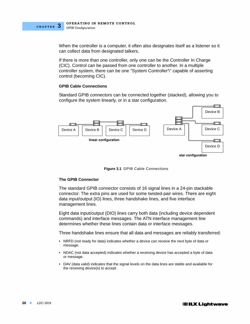
GPIB Cable Connections
Standard GPIB connectors can be connected together (stacked), allowing you to configure the system linearly, or in a star configuration.
Figure 3.1 GPIB Cable Connections
The GPIB Connector
The standard GPIB connector consists of 16 signal lines in a 24-pin stackable connector. The extra pins are used for some twisted-pair wires. There are eight data input/output (IO) lines, three handshake lines, and five interface management lines.
Eight data input/output (DIO) lines carry both data (including device dependent commands) and interface messages. The ATN interface management line determines whether these lines contain data or interface messages.
Three handshake lines ensure that all data and messages are reliably transferred:
• NRFD (not ready for data) indicates whether a device can receive the next byte of data or message.
• NDAC (not data accepted) indicates whether a receiving device has accepted a byte of data or message.
• DAV (data valid) indicates that the signal levels on the data lines are stable and available for the receiving device(s) to accept.
Device A Device B Device C Device D Device A
Device B
Device C
Device D
linear configuration
star configuration
O P E R A T I N G I N RE M O T E C O N T R O LGPIB Configuration
07_15 LDC-3916 27
C H A P T E R 3
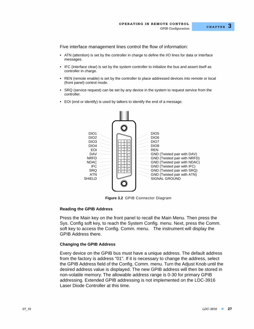
Five interface management lines control the flow of information:
• ATN (attention) is set by the controller in charge to define the I/O lines for data or interface messages.
• IFC (interface clear) is set by the system controller to initialize the bus and assert itself as controller in charge.
• REN (remote enable) is set by the controller to place addressed devices into remote or local (front panel) control mode.
• SRQ (service request) can be set by any device in the system to request service from the controller.
• EOI (end or identify) is used by talkers to identify the end of a message.
Figure 3.2 GPIB Connector Diagram
Reading the GPIB Address
Press the Main key on the front panel to recall the Main Menu. Then press the Sys. Config soft key, to reach the System Config. menu. Next, press the Comm. soft key to access the Config. Comm. menu. The instrument will display the GPIB Address there.
Changing the GPIB Address
Every device on the GPIB bus must have a unique address. The default address from the factory is address "01". If it is necessary to change the address, select the GPIB Address field of the Config. Comm. menu. Turn the Adjust Knob until the desired address value is displayed. The new GPIB address will then be stored in non-volatile memory. The allowable address range is 0-30 for primary GPIB addressing. Extended GPIB addressing is not implemented on the LDC-3916 Laser Diode Controller at this time.
123456789
101112
131415161718192021222324
DIO5DIO6DIO7DIO8RENGND (Twisted pair with DAV)GND (Twisted pair with NRFD)GND (Twisted pair with NDAC)GND (Twisted pair with IFC)GND (Twisted pair with SRQ)GND (Twisted pair with ATN)SIGNAL GROUND
DIO1DIO2DIO3DIO4
EOIDAV
NRFDNDAC
IFCSRQATN
SHIELD
O P E R A T I N G I N R E M O T E C O N T R O LGPIB Configuration
28 LDC-3916
C H A P T E R 3
RS-232 Configuration
The instrument's baud rate setting must match the baud rate used by the serial RS-232 interface, which is typically a serial COMM port on your PC. This section describes reading and changing the baud rate of the LDC-3916.
The LDC-3916's RS-232 is configured for 8-bit, no parity. This is not adjustable. Only the baud rate may be altered.
Reading the Baud Rate
Press the Main key on the front panel to recall the Main Menu. Then press the Sys. Config. soft key, to reach the System Config. menu. Next, press the Comm. soft key to access the Config Comm. menu. The instrument will display the baud rate there.
Changing the Baud Rate
The factory default baud rate is 19200. If it is necessary to change the baud rate, select the Baud rate field of the Config. Comm. menu. Turn the Adjust Knob until the desired baud rate value is displayed. The new baud rate will then be stored in non-volatile memory. The allowable baud rates are 1200, 2400, 4800, 9600, and 19200. Refer to the serial port configuration of your PC (if used) for the appropriate baud rate.
Changing Operation from Local to Remote
Sending a command over the GPIB or RS-232 interface will automatically put the instrument in REMOTE mode. The REMOTE indicator on the lower right of the front panel will illuminate when the controller is in remote operation mode. When the instrument is in REMOTE mode, pressing the LOCAL switch on the front panel returns the instrument to LOCAL control mode unless a Local Lockout state has been activated by the low level GPIB command LLO from the host computer (GPIB only). Local Lockout disables all LDC-3916 front panel switches until this condition is changed by the host computer. In this condition, the REMOTE indicator will flash at a 1 Hz rate. Menu changes are allowed by using the soft keys in Remote mode. Changing channels is allowed by using the Adjust Knob or Arrow keys. Other items in menus such as setpoint adjustments, mode changes, cursor movements or turning the TEC/laser on or off are not allowed.
The TALK/LISTEN indicator on the front panel is illuminated when the instrument is communicating over the GPIB or RS-232 interface.
For more information on low level commands such as LLO, refer to the IEEE488.1 specification.
O P E R A T I N G I N RE M O T E C O N T R O LGPIB Configuration
07_15 LDC-3916 29
C H A P T E R 3
GPIB Versus RS-232 Communications
The LDC-3916 should not be run remotely via GPIB and RS-232 at the same time. When using the RS-232 interface, the remote GPIB command set is fully operable. Command syntax does not vary between GPIB and RS-232 usage. However, the commands which affect GPIB hardware operation will not be useful. For example, the user could send the "*SRE" command via RS-232. However, any service request (SRQ) via GPIB would not be visible since RS-232 has no hardware to support it. This is because SRQ is a function of the GPIB interface hardware and is not available via RS-232.
O P E R A T I N G I N R E M O T E C O N T R O LLaser Diode Controller Command Set
30 LDC-3916
C H A P T E R 3
Laser Diode Controller Command Set
This section contains information about the LDC-3916's mainframe command set, command syntax, and error and status registers. For the most efficient and effective remote control of your controller, we recommend you study the following sections. For module-specific commands, refer to the GPIB section of the instruction manual for that module.
Command Syntax
This section describes command syntax and structure. You need this information to effectively write GPIB control programs. The syntax of GPIB commands follow the rules difined in the ANSI/IEEE 488.2-1987 standard.
Letters
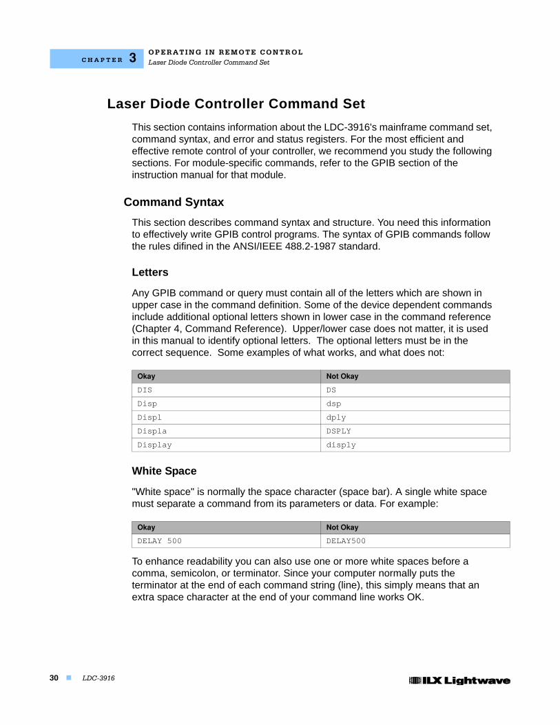
Any GPIB command or query must contain all of the letters which are shown in upper case in the command definition. Some of the device dependent commands include additional optional letters shown in lower case in the command reference (Chapter 4, Command Reference). Upper/lower case does not matter, it is used in this manual to identify optional letters. The optional letters must be in the correct sequence. Some examples of what works, and what does not:
White Space
"White space" is normally the space character (space bar). A single white space must separate a command from its parameters or data. For example:
To enhance readability you can also use one or more white spaces before a comma, semicolon, or terminator. Since your computer normally puts the terminator at the end of each command string (line), this simply means that an extra space character at the end of your command line works OK.
Okay Not Okay
DIS DS
Disp dsp
Displ dply
Displa DSPLY
Display disply
Okay Not Okay
DELAY 500 DELAY500
O P E R A T I N G I N RE M O T E C O N T R O LLaser Diode Controller Command Set
07_15 LDC-3916 31
C H A P T E R 3
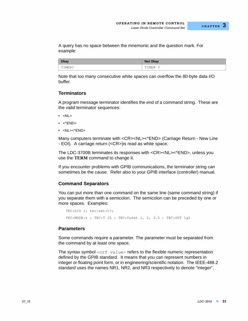
A query has no space between the mnemonic and the question mark. For example:
Note that too many consecutive white spaces can overflow the 80-byte data I/O buffer.
Terminators
A program message terminator identifies the end of a command string. These are the valid terminator sequences:
• <NL>
• <^END>
• <NL><^END>
Many computers terminate with <CR><NL><^END> (Carriage Return - New Line - EOI). A carriage return (<CR>)is read as white space.
The LDC-3700B terminates its responses with <CR><NL><^END>, unless you use the TERM command to change it.
If you encounter problems with GPIB communications, the terminator string can sometimes be the cause. Refer also to your GPIB interface (controller) manual.
Command Separators
You can put more than one command on the same line (same command string) if you separate them with a semicolon. The semicolon can be preceded by one or more spaces. Examples:
TEC:DIS 1; tec:set:t?;
TEC:MODE:t ; TEC:T 25 ; TEC:Const 1, 2, 3.5 ; TEC:OUT 1g1
Parameters
Some commands require a parameter. The parameter must be separated from the command by at least one space.
The syntax symbol <nrf value> refers to the flexible numeric representation defined by the GPIB standard. It means that you can represent numbers in integer or floating point form, or in engineering/scientific notation. The IEEE-488.2 standard uses the names NR1, NR2, and NR3 respectively to denote "integer",
Okay Not Okay
TIMER? TIMER ?
O P E R A T I N G I N R E M O T E C O N T R O LLaser Diode Controller Command Set
32 LDC-3916
C H A P T E R 3
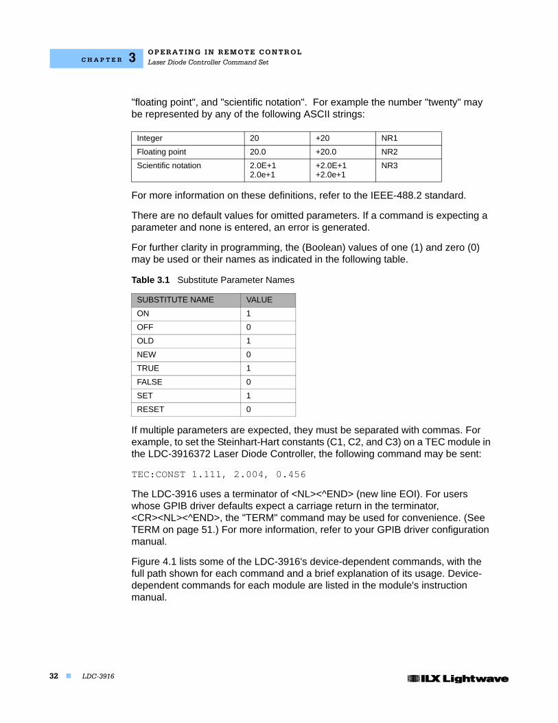
"floating point", and "scientific notation". For example the number "twenty" may be represented by any of the following ASCII strings:
For more information on these definitions, refer to the IEEE-488.2 standard.
There are no default values for omitted parameters. If a command is expecting a parameter and none is entered, an error is generated.
For further clarity in programming, the (Boolean) values of one (1) and zero (0) may be used or their names as indicated in the following table.
If multiple parameters are expected, they must be separated with commas. For example, to set the Steinhart-Hart constants (C1, C2, and C3) on a TEC module in the LDC-3916372 Laser Diode Controller, the following command may be sent:
TEC:CONST 1.111, 2.004, 0.456
The LDC-3916 uses a terminator of <NL><^END> (new line EOI). For users whose GPIB driver defaults expect a carriage return in the terminator, <CR><NL><^END>, the "TERM" command may be used for convenience. (See TERM on page 51.) For more information, refer to your GPIB driver configuration manual.
Figure 4.1 lists some of the LDC-3916's device-dependent commands, with the full path shown for each command and a brief explanation of its usage. Device-dependent commands for each module are listed in the module's instruction manual.
Integer 20 +20 NR1
Floating point 20.0 +20.0 NR2
Scientific notation 2.0E+12.0e+1
+2.0E+1+2.0e+1
NR3
Table 3.1 Substitute Parameter Names
SUBSTITUTE NAME VALUE
ON 1
OFF 0
OLD 1
NEW 0
TRUE 1
FALSE 0
SET 1
RESET 0
O P E R A T I N G I N RE M O T E C O N T R O LLaser Diode Controller Command Set
07_15 LDC-3916 33
C H A P T E R 3
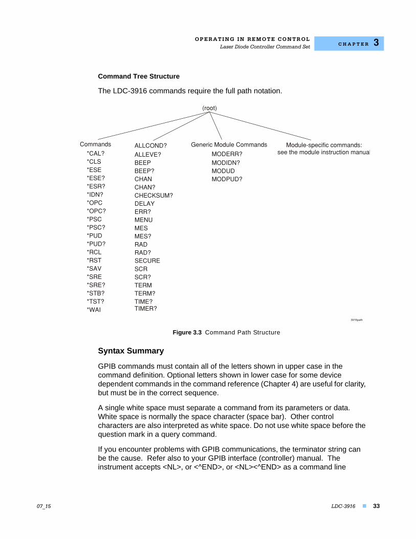
Command Tree Structure
The LDC-3916 commands require the full path notation.
Figure 3.3 Command Path Structure
Syntax Summary
GPIB commands must contain all of the letters shown in upper case in the command definition. Optional letters shown in lower case for some device dependent commands in the command reference (Chapter 4) are useful for clarity, but must be in the correct sequence.
A single white space must separate a command from its parameters or data. White space is normally the space character (space bar). Other control characters are also interpreted as white space. Do not use white space before the question mark in a query command.
If you encounter problems with GPIB communications, the terminator string can be the cause. Refer also to your GPIB interface (controller) manual. The instrument accepts <NL>, or <^END>, or <NL><^END> as a command line
(root)
Commands Generic Module Commands Module−specific commands: see the module instruction manual*CAL? MODERR?
ALLCOND?
*CLS MODIDN?ALLEVE?
*ESE MODUDBEEP
*ESE? MODPUD?BEEP?
*ESR?CHAN
*IDN?CHAN?
*OPCCHECKSUM?
*OPC?DELAY
*PSCERR?
*PSC?MENU
*PUDMES
*PUD?MES?
*RCLRAD
*RSTRAD?
*SAVSECURE
*SRESCR
*SRE?SCR?
*STB?TERM
*TST?TERM?
*WAITIME?TIMER?
O P E R A T I N G I N R E M O T E C O N T R O LLaser Diode Controller Command Set
34 LDC-3916
C H A P T E R 3
terminator. Many computers terminate with <CR> <NL> <^END> (Carriage Return - New Line - EOI). The instrument ignores <CR> (Carriage Return) as white space. The LDC-3916 terminates its responses with <CR><NL><^END>, unless you use the TERM command to change it.
You can put more than one command on the same line (same command string) if you separate them with a semicolon.
GPIB uses a flexible representation for numeric parameters: integer, floating point, or engineering/scientific notation. There are no default values for omitted parameters.
Some device-dependent GPIB commands are compound commands, in which the first mnemonic opens a path to a set of commands relating to that path. The second mnemonic then defines the actual command.
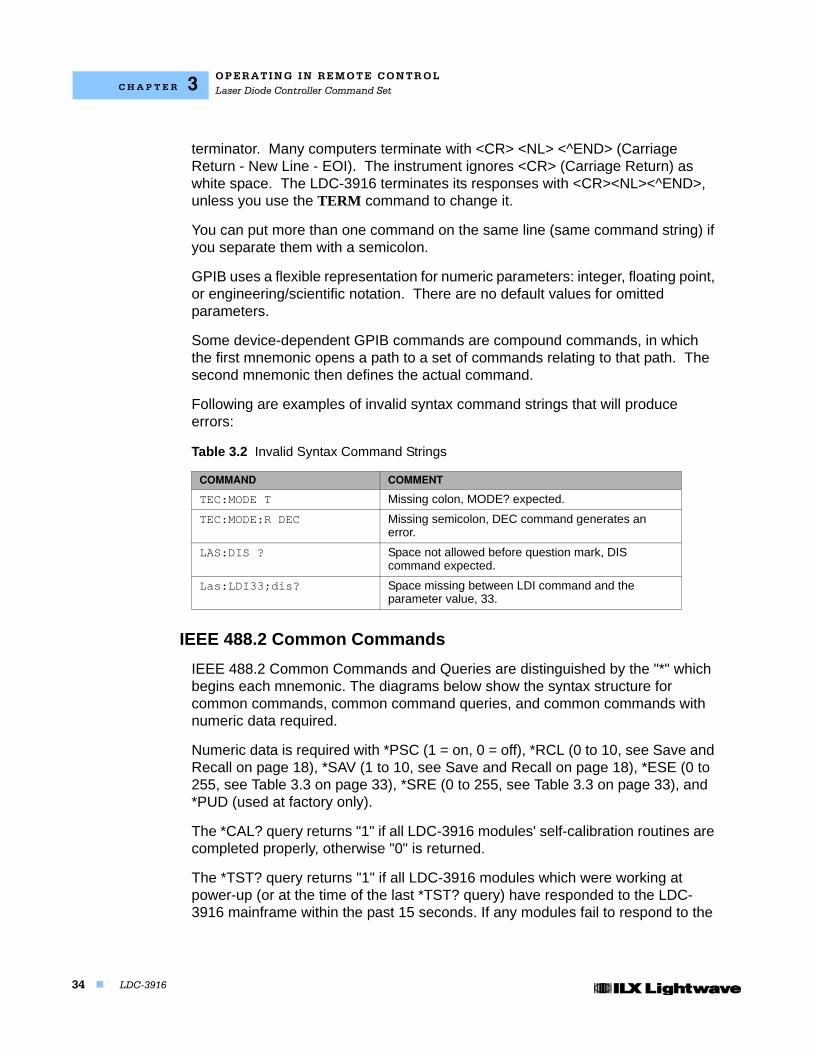
Following are examples of invalid syntax command strings that will produce errors:
IEEE 488.2 Common Commands
IEEE 488.2 Common Commands and Queries are distinguished by the "*" which begins each mnemonic. The diagrams below show the syntax structure for common commands, common command queries, and common commands with numeric data required.
Numeric data is required with *PSC (1 = on, 0 = off), *RCL (0 to 10, see Save and Recall on page 18), *SAV (1 to 10, see Save and Recall on page 18), *ESE (0 to 255, see Table 3.3 on page 33), *SRE (0 to 255, see Table 3.3 on page 33), and *PUD (used at factory only).
The *CAL? query returns "1" if all LDC-3916 modules' self-calibration routines are completed properly, otherwise "0" is returned.
The *TST? query returns "1" if all LDC-3916 modules which were working at power-up (or at the time of the last *TST? query) have responded to the LDC-3916 mainframe within the past 15 seconds. If any modules fail to respond to the
Table 3.2 Invalid Syntax Command Strings
COMMAND COMMENT
TEC:MODE T Missing colon, MODE? expected.
TEC:MODE:R DEC Missing semicolon, DEC command generates an error.
LAS:DIS ? Space not allowed before question mark, DIS command expected.
Las:LDI33;dis? Space missing between LDI command and the parameter value, 33.
O P E R A T I N G I N RE M O T E C O N T R O LStatus Reporting
07_15 LDC-3916 35
C H A P T E R 3
mainframe, *TST? will return "0", and those modules will no longer be recognized by the system.
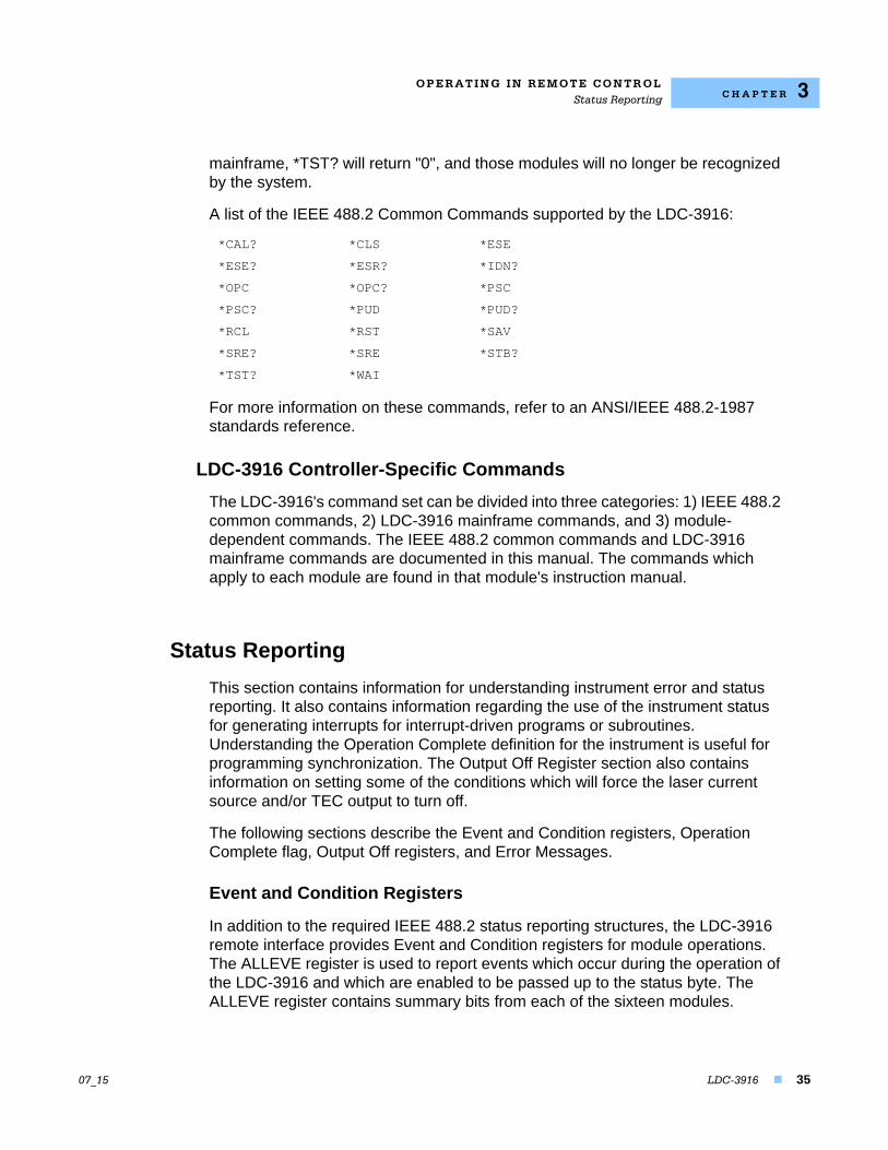
A list of the IEEE 488.2 Common Commands supported by the LDC-3916:
For more information on these commands, refer to an ANSI/IEEE 488.2-1987 standards reference.
LDC-3916 Controller-Specific Commands
The LDC-3916's command set can be divided into three categories: 1) IEEE 488.2 common commands, 2) LDC-3916 mainframe commands, and 3) module-dependent commands. The IEEE 488.2 common commands and LDC-3916 mainframe commands are documented in this manual. The commands which apply to each module are found in that module's instruction manual.
Status Reporting
This section contains information for understanding instrument error and status reporting. It also contains information regarding the use of the instrument status for generating interrupts for interrupt-driven programs or subroutines. Understanding the Operation Complete definition for the instrument is useful for programming synchronization. The Output Off Register section also contains information on setting some of the conditions which will force the laser current source and/or TEC output to turn off.
The following sections describe the Event and Condition registers, Operation Complete flag, Output Off registers, and Error Messages.
Event and Condition Registers
In addition to the required IEEE 488.2 status reporting structures, the LDC-3916 remote interface provides Event and Condition registers for module operations. The ALLEVE register is used to report events which occur during the operation of the LDC-3916 and which are enabled to be passed up to the status byte. The ALLEVE register contains summary bits from each of the sixteen modules.
*CAL? *CLS *ESE
*ESE? *ESR? *IDN?
*OPC *OPC? *PSC
*PSC? *PUD *PUD?
*RCL *RST *SAV
*SRE? *SRE *STB?
*TST? *WAI
O P E R A T I N G I N R E M O T E C O N T R O LStatus Reporting
36 LDC-3916
C H A P T E R 3
Likewise, the ALLCOND register is used to report conditions which occur during the operation of the LDC-3916, and which are enabled to be passed on to the status byte. The ALLCOND register contains summary bits from each of the sixteen modules.
The bits in the ALLCOND and ALLEVE registers are logically ORed to form a summary message in the status byte for that particular register.
Events are different from conditions. Events signal one-time occurrences and are not reset until either the corresponding module's Event Register(s) is queried, the *CLS command is issued, or the LDC-3916 is powered off. Conditions reflect the current state of the device and therefore may change many times during operation.
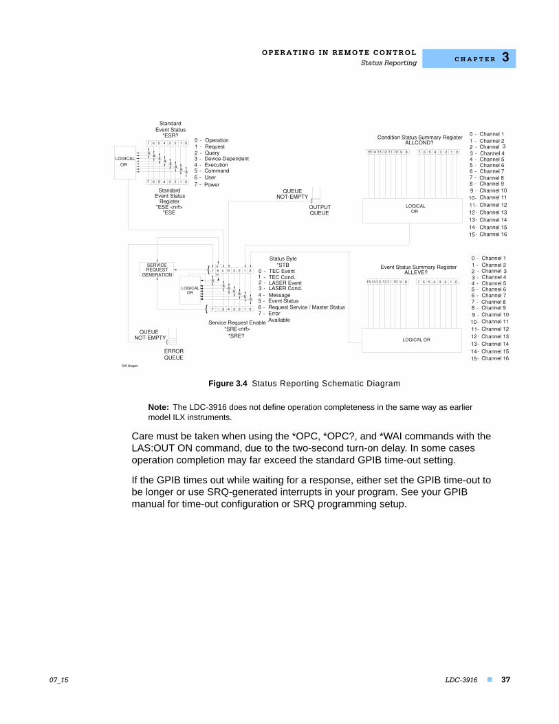
Figure 3.2 shows the status reporting scheme of the LDC-3916 Laser Diode Controller.
Operation Complete Definition
Note that Bit 0 of the Standard Event Status register contains the status of the Operation Complete flag. Enabling this bit via the *ESE command allows the user to update Bit 5 of the status byte. Then, if the SRE mask has bit 5 set, and the user issues an *OPC command, the SRQ signal will be generated upon completion of the currently processed commands. This may be used to initiate service request routines which depend on the completion of all previous commands.
The LDC-3916 defines Operation Completeness to be the state when all sequential and overlapped commands are completed. Most LDC-3916 commands are sequential; only a few are overlapped. Refer to your module's instruction manual for a list of overlapped commands.
O P E R A T I N G I N RE M O T E C O N T R O LStatus Reporting
07_15 LDC-3916 37
C H A P T E R 3
Figure 3.4 Status Reporting Schematic Diagram
Note: The LDC-3916 does not define operation completeness in the same way as earlier model ILX instruments.
Care must be taken when using the *OPC, *OPC?, and *WAI commands with the LAS:OUT ON command, due to the two-second turn-on delay. In some cases operation completion may far exceed the standard GPIB time-out setting.
If the GPIB times out while waiting for a response, either set the GPIB time-out to be longer or use SRQ-generated interrupts in your program. See your GPIB manual for time-out configuration or SRQ programming setup.
LOGICALOR
9 8
ALLCOND?Condition Status Summary Register
01234567
01234567
7 6 5 4 3 2 1 0
&&
&&
&&
&&
LOGICALOR
StandardEvent Status
Register*ESE <nrf>
*ESE
Service Request Enable*SRE<nrf>
*SRE?
LOGICALOR
&&
&&
&&
&
0123ME67
7 5 4 3 2 1 0
7 − Power6 − User5 − Command4 − Execution3 − Device−Dependent2 − Query1 − Request0 Operation−
7 − ErrorAvailable
6 − Request Service / Master Status5 − Event Status4 − Message3 − LASER Cond.2 − LASER Event1 − TEC Cond.0 TEC Event−
*STBStatus Byte
R
M
SERVICEREQUEST
GENERATION
{OUTPUTQUEUE
QUEUENOT−EMPTY
QUEUENOT−EMPTY
ERRORQUEUE
{
11−10−9 −8 − Channel 97 − Channel 86 − Channel 75 − Channel 64 − Channel 53 − Channel 42 − Channel 31 − Channel 20 Channel 1−
{
{
Event StatusStandard
*ESR?
15141312
Channel 10Channel 11Channel 12
−
−−−
Channel 16Channel 15Channel 14Channel 13
11−10−9 −8 − Channel 97 − Channel 86 − Channel 75 − Channel 64 − Channel 53 −2 − Channel 31 − Channel 20 Channel 1−
15141312
Channel 10Channel 11Channel 12
−
−−−
Channel 16Channel 15Channel 14Channel 13
Channel 4
LOGICAL OR
10
10
11
11
12
12
13
13
14
14
15
15
9 8
ALLEVE?Event Status Summary Register
01234567
O P E R A T I N G I N R E M O T E C O N T R O LStatus Reporting
38 LDC-3916
C H A P T E R 3
Command Timing
This section describes, for each device-dependent command, whether that command is performed in an overlapped or sequential manner. In other words, it states whether the next command may begin while this command is being executed, or if the next command must wait until this command is completed before its execution begins. See Operation Complete Definition on page 36 for conditions about setting the operation complete flag.
Sequential/Overlapped Commands
All device-dependent commands are executed in an overlapped manner: subsequent commands may begin before the current command is completed. Some common commands are sequential; the next command must wait until this command is completed. All device-dependent commands are executed in an overlapped manner, except the "DELAY" command which is sequential. The operation complete flag is set after the conditions outlined in the Operation Complete Definition have been satisfied.
The *WAI (common command) is an example of a sequential command which forces the next command to wait until the no-operation-pending flag is true. This is essentially the same as waiting for the OPC flag to become true, because the no-operations-pending flag is used to set the OPC flag (bit 0 of the Standard Event Status Register).
Commands which change the status of the instrument limits, or change its mode or current range, step value, or status enable registers, will not have their OPC flag set until all current writing to non-volatile memory has been completed. This ensures the OPC flag is never set prematurely.
Query Response Timing
Query responses are evaluated at the time the query request is parsed, and not at the time the response message is sent. In most cases this does not create a problem since the time between parsing a query and sending its response is small.
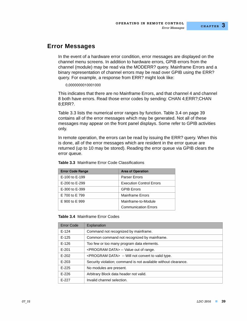
O P E R A T I N G I N RE M O T E C O N T R O LError Messages
07_15 LDC-3916 39
C H A P T E R 3
Error Messages
In the event of a hardware error condition, error messages are displayed on the channel menu screens. In addition to hardware errors, GPIB errors from the channel (module) may be read via the MODERR? query. Mainframe Errors and a binary representation of channel errors may be read over GPIB using the ERR? query. For example, a response from ERR? might look like:
0,0000000010001000
This indicates that there are no Mainframe Errors, and that channel 4 and channel 8 both have errors. Read those error codes by sending: CHAN 4;ERR?;CHAN 8;ERR?.
Table 3.3 lists the numerical error ranges by function. Table 3.4 on page 39 contains all of the error messages which may be generated. Not all of these messages may appear on the front panel displays. Some refer to GPIB activities only.
In remote operation, the errors can be read by issuing the ERR? query. When this is done, all of the error messages which are resident in the error queue are returned (up to 10 may be stored). Reading the error queue via GPIB clears the error queue.
Table 3.3 Mainframe Error Code Classifications
Error Code Range Area of Operation
E-100 to E-199 Parser Errors
E-200 to E-299 Execution Control Errors
E-300 to E-399 GPIB Errors
E 700 to E 799 Mainframe Errors
E 900 to E 999 Mainframe-to-Module
Communication Errors
Table 3.4 Mainframe Error Codes
Error Code Explanation
E-124 Command not recognized by mainframe.
E-125 Common command not recognized by mainframe.
E-126 Too few or too many program data elements.
E-201 <PROGRAM DATA> -- Value out of range.
E-202 <PROGRAM DATA> -- Will not convert to valid type.
E-203 Security violation; command is not available without clearance.
E-225 No modules are present.
E-226 Arbitrary Block data header not valid.
E-227 Invalid channel selection.
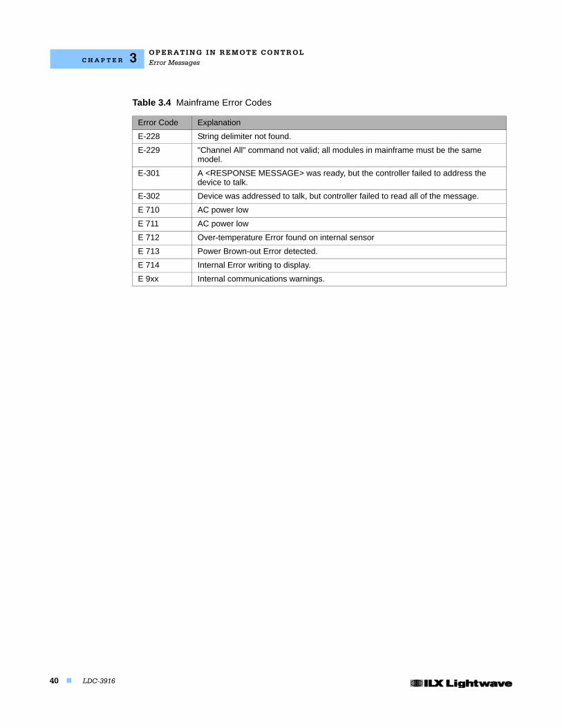
O P E R A T I N G I N R E M O T E C O N T R O LError Messages
40 LDC-3916
C H A P T E R 3
E-228 String delimiter not found.
E-229 "Channel All" command not valid; all modules in mainframe must be the same model.
E-301 A <RESPONSE MESSAGE> was ready, but the controller failed to address the device to talk.
E-302 Device was addressed to talk, but controller failed to read all of the message.
E 710 AC power low
E 711 AC power low
E 712 Over-temperature Error found on internal sensor
E 713 Power Brown-out Error detected.
E 714 Internal Error writing to display.
E 9xx Internal communications warnings.
Table 3.4 Mainframe Error Codes
Error Code Explanation
LDC-3916 41
C H A P T E R 4
COMMAND REFERENCE
This chapter is a guide to all of the mainframe device-dependent commands for the LDC-3916 Laser Diode Controller. The chapter is divided into two parts. The first contains an overview of the remote commands used by the LDC-3916, as shown in Table 4.1. The second part contains all of the LDC-3916 command descriptions, listed in alphabetical order.
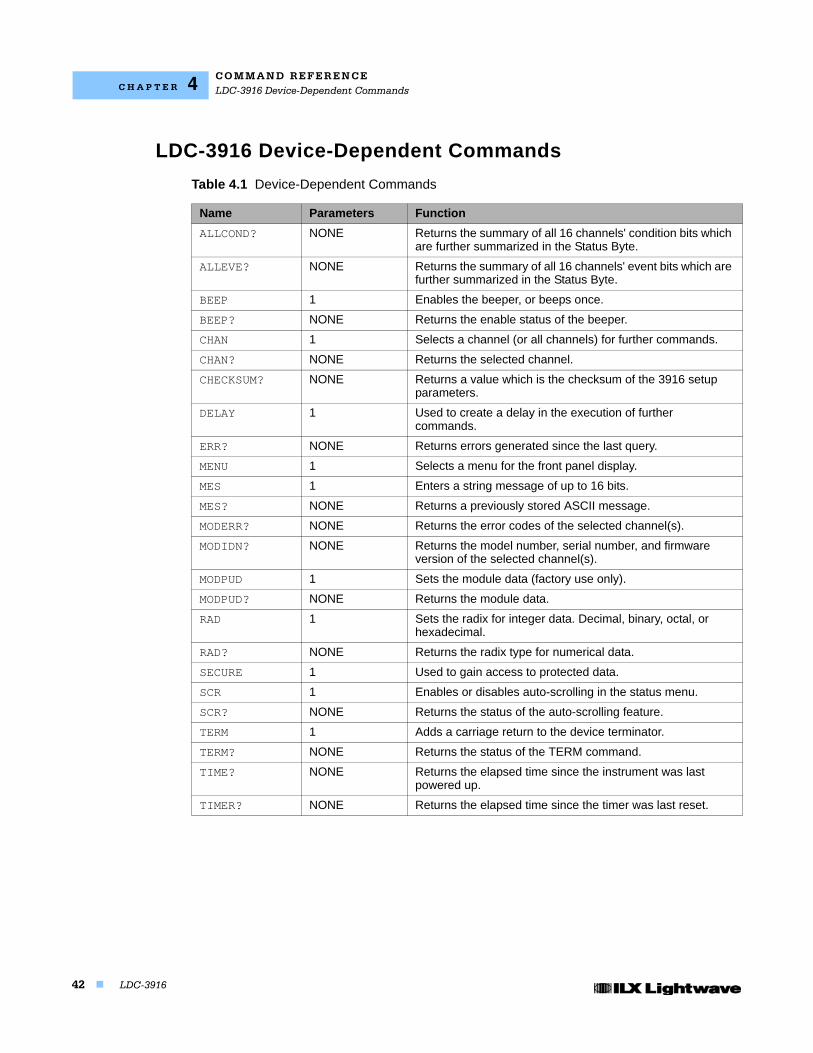
C O M M A N D R E F E R E N C ELDC-3916 Device-Dependent Commands
42 LDC-3916
C H A P T E R 4
LDC-3916 Device-Dependent Commands
Table 4.1 Device-Dependent Commands
Name Parameters Function
ALLCOND? NONE Returns the summary of all 16 channels' condition bits which are further summarized in the Status Byte.
ALLEVE? NONE Returns the summary of all 16 channels' event bits which are further summarized in the Status Byte.
BEEP 1 Enables the beeper, or beeps once.
BEEP? NONE Returns the enable status of the beeper.
CHAN 1 Selects a channel (or all channels) for further commands.
CHAN? NONE Returns the selected channel.
CHECKSUM? NONE Returns a value which is the checksum of the 3916 setup parameters.
DELAY 1 Used to create a delay in the execution of further commands.
ERR? NONE Returns errors generated since the last query.
MENU 1 Selects a menu for the front panel display.
MES 1 Enters a string message of up to 16 bits.
MES? NONE Returns a previously stored ASCII message.
MODERR? NONE Returns the error codes of the selected channel(s).
MODIDN? NONE Returns the model number, serial number, and firmware version of the selected channel(s).
MODPUD 1 Sets the module data (factory use only).
MODPUD? NONE Returns the module data.
RAD 1 Sets the radix for integer data. Decimal, binary, octal, or hexadecimal.
RAD? NONE Returns the radix type for numerical data.
SECURE 1 Used to gain access to protected data.
SCR 1 Enables or disables auto-scrolling in the status menu.
SCR? NONE Returns the status of the auto-scrolling feature.
TERM 1 Adds a carriage return to the device terminator.
TERM? NONE Returns the status of the TERM command.
TIME? NONE Returns the elapsed time since the instrument was last powered up.
TIMER? NONE Returns the elapsed time since the timer was last reset.
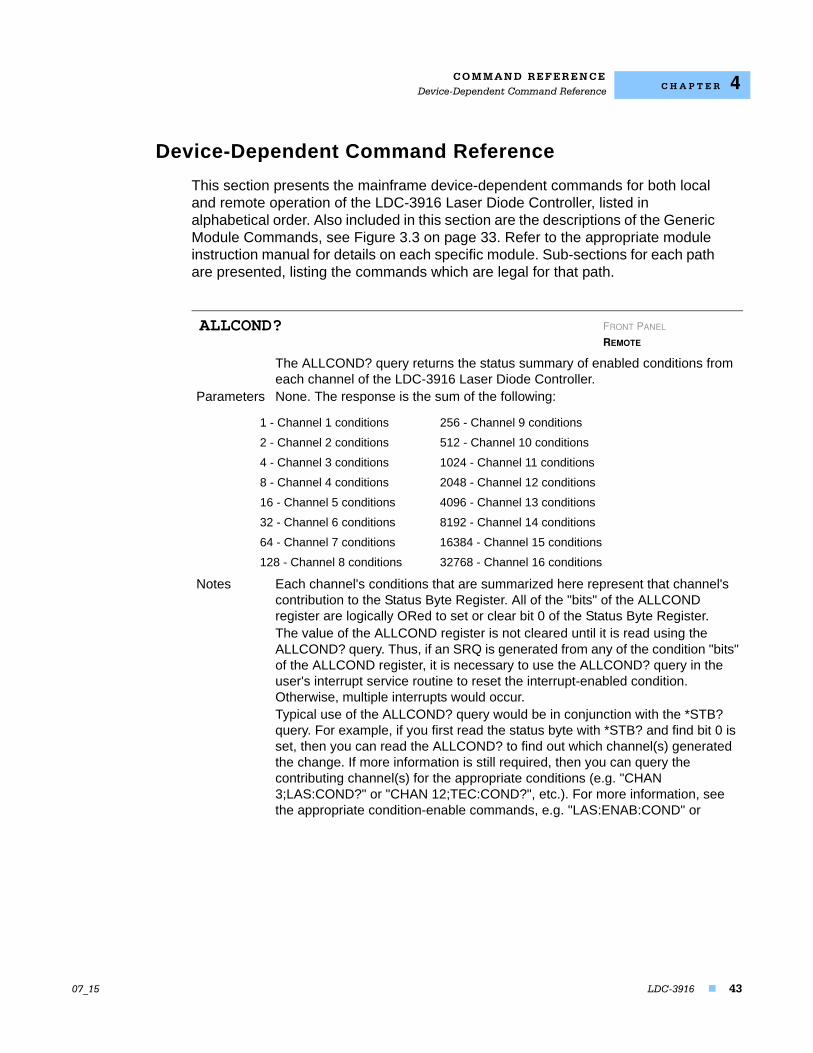
C O M M A N D R E F E R E N C EDevice-Dependent Command Reference
07_15 LDC-3916 43
C H A P T E R 4
Device-Dependent Command Reference
This section presents the mainframe device-dependent commands for both local and remote operation of the LDC-3916 Laser Diode Controller, listed in alphabetical order. Also included in this section are the descriptions of the Generic Module Commands, see Figure 3.3 on page 33. Refer to the appropriate module instruction manual for details on each specific module. Sub-sections for each path are presented, listing the commands which are legal for that path.
The ALLCOND? query returns the status summary of enabled conditions from each channel of the LDC-3916 Laser Diode Controller.
Parameters None. The response is the sum of the following:
Notes Each channel's conditions that are summarized here represent that channel's contribution to the Status Byte Register. All of the "bits" of the ALLCOND register are logically ORed to set or clear bit 0 of the Status Byte Register. The value of the ALLCOND register is not cleared until it is read using the ALLCOND? query. Thus, if an SRQ is generated from any of the condition "bits" of the ALLCOND register, it is necessary to use the ALLCOND? query in the user's interrupt service routine to reset the interrupt-enabled condition. Otherwise, multiple interrupts would occur.Typical use of the ALLCOND? query would be in conjunction with the *STB? query. For example, if you first read the status byte with *STB? and find bit 0 is set, then you can read the ALLCOND? to find out which channel(s) generated the change. If more information is still required, then you can query the contributing channel(s) for the appropriate conditions (e.g. "CHAN 3;LAS:COND?" or "CHAN 12;TEC:COND?", etc.). For more information, see the appropriate condition-enable commands, e.g. "LAS:ENAB:COND" or
ALLCOND? FRONT PANEL
REMOTE
1 - Channel 1 conditions 256 - Channel 9 conditions
2 - Channel 2 conditions 512 - Channel 10 conditions
4 - Channel 3 conditions 1024 - Channel 11 conditions
8 - Channel 4 conditions 2048 - Channel 12 conditions
16 - Channel 5 conditions 4096 - Channel 13 conditions
32 - Channel 6 conditions 8192 - Channel 14 conditions
64 - Channel 7 conditions 16384 - Channel 15 conditions
128 - Channel 8 conditions 32768 - Channel 16 conditions
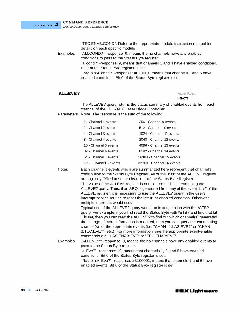
C O M M A N D R E F E R E N C EDevice-Dependent Command Reference
44 LDC-3916
C H A P T E R 4
"TEC:ENAB:COND". Refer to the appropriate module instruction manual for details on each specific module.
Examples "ALLCOND?" -response: 0, means the no channels have any enabled conditions to pass to the Status Byte register."allcond?" -response: 9, means that channels 1 and 4 have enabled conditions. Bit 0 of the Status Byte register is set."Rad bin;Allcond?" -response: #B10001, means that channels 1 and 5 have enabled conditions. Bit 0 of the Status Byte register is set.
The ALLEVE? query returns the status summary of enabled events from each channel of the LDC-3916 Laser Diode Controller.
Parameters None. The response is the sum of the following:
Notes Each channel's events which are summarized here represent that channel's contribution to the Status Byte Register. All of the "bits" of the ALLEVE register are logically ORed to set or clear bit 1 of the Status Byte Register. The value of the ALLEVE register is not cleared until it is read using the ALLEVE? query. Thus, if an SRQ is generated from any of the event "bits" of the ALLEVE register, it is necessary to use the ALLEVE? query in the user's interrupt service routine to reset the interrupt-enabled condition. Otherwise, multiple interrupts would occur.Typical use of the ALLEVE? query would be in conjunction with the *STB? query. For example, if you first read the Status Byte with *STB? and find that bit 1 is set, then you can read the ALLEVE? to find out which channel(s) generated the change. If more information is required, then you can query the contributing channel(s) for the appropriate events (i.e. "CHAN 11;LAS:EVE?" or "CHAN 3;TEC:EVE?", etc.). For more information, see the appropriate event-enable commands,e.g. "LAS:ENAB:EVE" or "TEC:ENAB:EVE".
Examples "ALLEVE?"" -response: 0, means the no channels have any enabled events to pass to the Status Byte register."allEve?" -response: 19, means that channels 1, 2, and 5 have enabled conditions. Bit 0 of the Status Byte register is set."Rad bin;AllEve?" -response: #B100001, means that channels 1 and 6 have enabled events. Bit 0 of the Status Byte register is set.
ALLEVE? FRONT PANEL
REMOTE
1 - Channel 1 events 256 - Channel 9 events
2 - Channel 2 events 512 - Channel 10 events
4 - Channel 3 events 1024 - Channel 11 events
8 - Channel 4 events 2048 - Channel 12 events
16 - Channel 5 events 4096 - Channel 13 events
32 - Channel 6 events 8192 - Channel 14 events
64 - Channel 7 events 16384 - Channel 15 events
128 - Channel 8 events 32768 - Channel 16 events
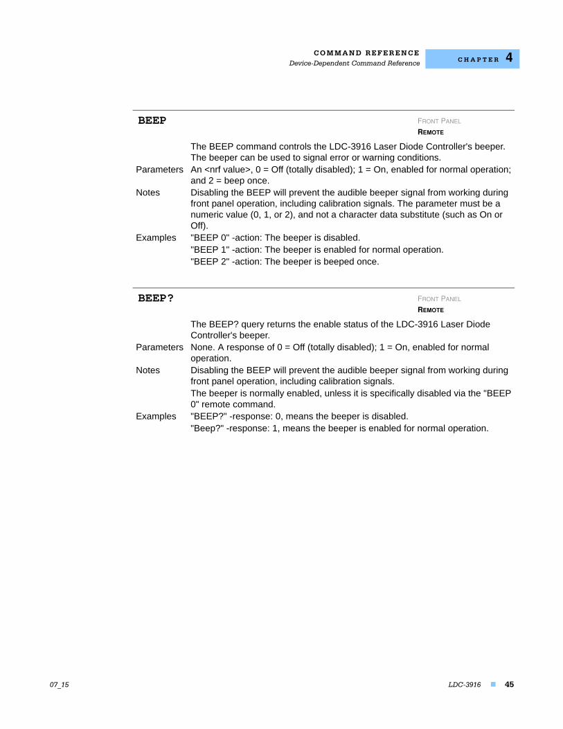
C O M M A N D R E F E R E N C EDevice-Dependent Command Reference
07_15 LDC-3916 45
C H A P T E R 4
The BEEP command controls the LDC-3916 Laser Diode Controller's beeper. The beeper can be used to signal error or warning conditions.
Parameters An <nrf value>, 0 = Off (totally disabled); 1 = On, enabled for normal operation; and 2 = beep once.
Notes Disabling the BEEP will prevent the audible beeper signal from working during front panel operation, including calibration signals. The parameter must be a numeric value (0, 1, or 2), and not a character data substitute (such as On or Off).
Examples "BEEP 0" -action: The beeper is disabled."BEEP 1" -action: The beeper is enabled for normal operation."BEEP 2" -action: The beeper is beeped once.
The BEEP? query returns the enable status of the LDC-3916 Laser Diode Controller's beeper.
Parameters None. A response of 0 = Off (totally disabled); 1 = On, enabled for normal operation.
Notes Disabling the BEEP will prevent the audible beeper signal from working during front panel operation, including calibration signals. The beeper is normally enabled, unless it is specifically disabled via the "BEEP 0" remote command.
Examples "BEEP?" -response: 0, means the beeper is disabled."Beep?" -response: 1, means the beeper is enabled for normal operation.
BEEP FRONT PANEL
REMOTE
BEEP? FRONT PANEL
REMOTE
C O M M A N D R E F E R E N C EDevice-Dependent Command Reference
46 LDC-3916
C H A P T E R 4
The CHANnel command selects the modules that will receive subsequent channel-based commands.
Parameters An <nrf value>, a list of comma-separated <nrf values>, or "ALL".-where the <nrf value> (1 - 16) represents an LDC-3916 channel number.
Notes The modules in the selected channels will receive all channel-based commands until the next "channel" command.Selecting a channel remotely does not affect the front panel display. To change the front panel display remotely, see "Menu" command.If an invalid (missing) module is selected, an "E227" error will be generated, and the channel will not be changed.
Examples "chan 1" -action: selects the module in channel 1 for further channel-based commands (assuming a module exists in the channel)."Chan 1,3,4,8" -action: selects the modules in channels 1, 3, 4,and 8 for further channel-based commands."Channel all" -action: selects all available modules for further channel-based commands
The CHANnel? query returns the channel numbers of the modules that have been selected to receive channel-based commands.
Parameters None. The response will be the channel numbers of the selected modules.Notes If no channels are found by the mainframe, the response will be 0.Examples "CHAN?" -response: "12", means the module in channel 12 is selected for
channel-based commands.":CHan?" -response: "3;4;16", means the modules in channels 3, 4, and 16 are selected for channel-based commands."channel?" -response: "ALL", means that channel-based commands will be sent to all available modules.
The CHECKSUM? query returns an integer value which is the summation of all pertinent parameters of the present configuration.
Parameters None. The response consists of an integer value.Notes The response value may be stored and compared at a later time to verify that
the present configuration of the instrument is the same as expected. This
CHANnel FRONT PANEL
REMOTE
CHANnel? FRONT PANEL
REMOTE
CHECKSUM? FRONT PANEL
REMOTE
C O M M A N D R E F E R E N C EDevice-Dependent Command Reference
07_15 LDC-3916 47
C H A P T E R 4
feature works well with the *RCL (recall) command as a means of verifying a stored setup.The checksum does not test the functionality of the instrument or which modules are present.
Examples "CHECKSUM?" -response: 3812, is the checksum of the present configuration of parameters on the instrument.
The DELAY command causes the execution of commands to be delayed by a user-defined time interval. This command is similar to the *WAI common command, except that execution resumes after the specified number of milliseconds, instead of waiting for the Operation-Complete flag to be set.
Parameters An <nrf value> which represents the delay time, in milliseconds. Notes Further commands are held off until the delay period elapses.
This command is useful for creating delays which do not require very much program code and do not tie up the GPIB during execution.
Examples "DELAY 500" -action: Further commands and queries are not executed until 0.5 second has elapsed from the time this command is executed."Tec:T 22;Delay 2000;Tec:T?" -actions: The TEC is set to 22.0C, then the LDC-3916 Laser Diode Controller waits for about 2.0 seconds before displaying the measured temperature.
The "ERRors?" query returns a list of "mainframe" device and command errors, followed by a binary representation of the occurrence of "module" device and command errors. The "mainframe" errors are those which have occurred since the last "ERR?" query. The "module" errors are not cleared until the "MODERR?" query is sent to each module which reports an error. The errors are notated by a number (code) which corresponds to the type of error which occurred. See Chapter 3, Error Messages, for information regarding error handling.
Parameters None. The response consists of one or more "mainframe" error code values, separated by commas and a 16-bit binary representation of errors which exist on each channel.
Notes A response of 0,0000000000000000 indicates that no errors were reported. The first zero indicates no "mainframe" errors, and the second (16-bit) zero indicates no "module" errors. The response data is sent as character data.
Examples "'ERR?" -response: 0,0000000000000001 means no "mainframe" errors reported, but channel #1 has an error. Use "Chan 1;MODERR?" to retrieve the error code(s) from channel 1."Errors?" -response: 219,1111111100000000, means that the LDC-3916 was unable to restore the setup parameters (at power-up) because of a change in modules. Also, there are errors present on channels 9 - 16.
DELAY FRONT PANEL
REMOTE
ERRors? FRONT PANEL
REMOTE
C O M M A N D R E F E R E N C EDevice-Dependent Command Reference
48 LDC-3916
C H A P T E R 4
The MENU command causes the front panel display to switch to the.Parameters An <nrf value> which represents the front panel menu selections. 1 = Channel
Menu, 2 = Status Menu, or 3 = Summary Menu. Notes This command is useful for visually monitoring activity from the front panel while
in remote operation. The channel used (when the parameter is 1) is the remotely selected channel, not the last front panel selected channel (see "Channel" command).
Examples "Menu 1" -action: sets the front panel display to the remotely selected channel's main menu."MENU 2" -action: sets the front panel display to the Status menu.
The MESsage command allows the user to enter an ASCII string of up to 16 non-zero characters. This command may be useful for storing messages which relate to a test or configuration.
Parameters An ASCII string that is 1 - 16 bytes in length.Notes The message may contain any ASCII character but will be terminated when a
"NULL" terminator character is received. If the message has less than 16 bytes, the software will fill the remaining message space with the space character. After 16 bytes have been entered, the software will null-terminate the string.
Examples MESSAGE "This is a test." -action: The string, "This is a test. ", will be stored in non-volatile memory.Mes "Test 3 "-action: The string, "Test 3 ", will be stored in non-volatile memory.
The MESsage? query returns the previously stored message. This message will always be 16 bytes long and enclosed in quotes. The message is entered via the MESsage command.
Parameters None. The response is a 16-byte-long character string.Notes The response data will be a 16-byte-long string. If there is no previously stored
message, the response will be " ", all spaces.Examples "MES?" -response: "Test 3", means the previously stored message was "Test
3"."Message?" -response: "This is a test. ", means the previously stored message was, "This is a test."
MENU FRONT PANEL
REMOTE
MESsage FRONT PANEL
REMOTE
MESsage? FRONT PANEL
REMOTE
C O M M A N D R E F E R E N C EDevice-Dependent Command Reference
07_15 LDC-3916 49
C H A P T E R 4
The MODERR? query returns a list of "module" device and command errors. The "module" errors are those which have occurred since the last "MODERR?" query. The errors are notated by a number (code) which corresponds to the type of error which occurred. See the appropriate module instruction manual for information regarding error handling for each specific module.
Parameters None. The response consists of one or more "module" error code values, separated by commas.
Notes A response of (0) indicates that no errors were reported. The response data is sent as character data.
Examples "MODERR?" -response: 0 means no "module" errors reported."Moderr?" -response: 501, means that the module has a LASER interlock error which prevented the LAS output from being turned on.
The MODIDN? query returns the module's model name and serial number.Parameters None. The response consists of the module's model number, serial number, and
version number, separated by commas.Notes The serial number may also be found by removing the module from the
mainframe and viewing the serial number information on the side of the module.Examples "MODIDN?" -response: "3916374,03740001,v1.00", for example.
The MODPUD command allows the service technician to enter the protected user data. This data is normally changed only at the factory, and therefore the MODPUD command is not needed by the user.
The MODPUD? query returns protected user data from a module. This data is entered by factory personnel when the module is calibrated.
Parameters None. The response consists of serial number, hardware version, option information, calibration date, and initials of the calibrating technician. The response is in the form of <arbitrary block data> with the header, #221, indicating twenty-one characters.
Notes The serial number may also be found by removing the module from the mainframe and viewing the serial number information on the side of the module.
Examples "MODPUD?" -response: #221037200020011120498grb
MODERR? FRONT PANEL
REMOTE
MODIDN? FRONT PANEL
REMOTE
MODPUD FRONT PANEL
REMOTE
MODPUD? FRONT PANEL
REMOTE

C O M M A N D R E F E R E N C EDevice-Dependent Command Reference
50 LDC-3916
C H A P T E R 4
The RADix command allows the programmer to select the radix type for status, condition, and event query response data. Decimal, binary, hexadecimal, and octal are allowed.
Parameters Character program data is expected, as shown above.Notes DECimal is the default type. Only the first three letters of the words decimal,
hexadecimal, binary, or octal are required.When the RADIX is selected, all status, condition, and event queries will return values in the new radix. In cases where the radix is not DECimal, the flexible numeric type <nrf value> (as shown in the Command Reference diagrams) will be replaced by HEX, BIN, or OCT representation. All of the above radixes may be used to enter program data at any time, without the need for issuing the RADix command. The proper prefix must also be used with Hex (#H), binary (#B), or octal (#Q). This command may be useful for setting up status reporting blocks. The bit-wise status representation may be more easily read in BIN, HEX, or OCT.
Examples "RAD dec" -action: the decimal radix is selected."rad hex; *ESR?" -action: the hexadecimal radix is selected; -response: #H80, means power-on was detected.
The RADix? query allows the programmer to determine which radix type for status, condition, and event query response data is currently selected. Decimal, binary, octal, and hexadecimal are allowed.
Parameters None. The response will be character data. A response of DEC means decimal, BIN means binary, HEX means hexadecimal, and OCT means octal.
Notes DEC is the default type. The LDC-3916 Laser Diode Controller defaults to this radix at power-up.The RADix command is used to select the desired radix. Once it is changed, the new radix will remain in effect until the power is shut off or a new RADix command is issued.
Examples "RAD?" -response: Dec, means the selected radix is decimal."rad?" -response: Hex, means the selected radix is hexadecimal."RADIX?" -response: Oct, means the selected radix is octal.
The SECURE command allows the service technician access to the protected user data command, *PUD, which is a common command. This data is normally
RADix FRONT PANEL
REMOTE
RADix? FRONT PANEL
REMOTE
SECURE FRONT PANEL
REMOTE
C O M M A N D R E F E R E N C EDevice-Dependent Command Reference
07_15 LDC-3916 51
C H A P T E R 4
changed only at the factory, and therefore the SECURE command is not needed by the user.
The SCRoll command enables or disables the auto-scrolling feature of the ALL status screen.
Parameters A Boolean value, 0 = FALSE (disabled), non-zero = TRUE (enabled). Notes This command affects the Status screen only.
The scrolling rate is not adjustable.When the auto-scrolling feature is enabled it is in effect until it is disabled or the LDC-3916 is powered off.
Examples "Scr 1" -action: Enables the auto-scrolling feature of the Status screen."SCROL 0" -action: Disables the auto-scrolling feature of the Status screen.
The SCRoll? query allows the programmer to determine the status of the auto-scrolling feature for the Status Menu.
Parameters None. The response is an <nrf value>, 1 = TRUE (enabled), 0 = FALSE (disabled).
Notes In local operation, the user must select the Status screen in order to determine if the auto-scrolling feature is in use.
Examples "Scroll?" -response: 1, means that auto-scrolling is enabled for the Status screen."SCR?" -response: 0, means that auto-scrolling is disabled for the Status screen.
The TERM command allows the programmer to change the default (IEEE488.2 standard) terminator to include the carriage return.
Parameters An <nrf value>, 0 = FALSE, non-zero = TRUENotes An altered terminator will be in the form <CR><NL><^END>. Technically this
takes the LDC-3916 Laser Diode Controller out of IEEE488.2 specification, but this command may be used for convenience when using non-standard GPIB controllers. This termination will be sent with all output until the "TERM 0" command is sent or the LDC-3916 Laser Diode Controller is powered off.
Examples "Term 1" -temporarily sets <CR><NL><^END> as the output terminator.
SCRoll FRONT PANEL
REMOTE
SCRoll? FRONT PANEL
REMOTE
TERM FRONT PANEL
REMOTE
C O M M A N D R E F E R E N C EDevice-Dependent Command Reference
52 LDC-3916
C H A P T E R 4
The TERM? query allows the programmer to determine whether the default (IEEE488.2 standard) terminator has been altered to include a carriage return.
Parameters None. The response is an <nrf value>, 1 = TRUE, 0 = FALSE.Notes An altered terminator will be in the form <CR><NL><^END>. This termination
will be sent with all output until the "TERM 0" command is sent or the LDC-3916 Laser Diode Controller is powered off.
Examples "Term?" -response: 1, means that the <CR><NL><^END> terminator is temporarily being used."Term?" -response: 0, means that the <NL><^END> terminator (IEEE 488.2 standard) is being used.
The TIME? query allows the programmer to determine how much time has passed since the LDC-3916 Laser Diode Controller was last powered up.
Parameters None. The response is character data in the form: hours:minutes:seconds.Notes The TIME clock is independent of the TIMER clock.Examples "Time?" -response: 00:01:02.36, means that 1 minute, 2.36 seconds have
passed since the LDC-3916 Laser Diode Controller was powered up. "TIME?" -response: 00:32:00.76, means that 32 minutes, 0.76 second have passed since the LDC-3916 Laser Diode Controller was powered up.
The TIMER? query allows the programmer to determine how much time has passed since the last TIMER? query was issued.
Parameters None. The response is character data in the form: hours:minutes:seconds.Notes Each time the TIMER? query is issued, the timer is reset to 0, and the elapsed
time since the last TIMER? query is returned.Examples "TIMER?" -response: 00:02:00.31, means the LDC-3916 Laser Diode Controller
has been on for 2 minutes, 0.31 seconds since the last TIMER? query was issued."TIMER?" -response: 00:00:12.03, means the LDC-3916 Laser Diode Controller has been on for 12.03 seconds since the last TIMER? query was issued.
TERM? FRONT PANEL
REMOTE
TIME? FRONT PANEL
REMOTE
TIMER? FRONT PANEL
REMOTE