Embed Size (px)
Citation preview
USERS MANUAL
2
User manual purpose This user manual is dedicated to the use of the bass amplifier GR 700+. The manual includes the following information: General information (technical data and packa-ging); Description of the amplifier’s functions.
All the informations described on this user manual are verified. The manufacturer reserves the right to update or modify their product without any notice.
PACKAGING AND STORAGE Packaging GR 700+ is packed in a special cardboard box. The box contains the amplifier GR700+, power sup-ply cable and the user manual.
TrasportPlease handle the box with care. A specific position during the transport is not required.
Storage Please keep the amplifier in a dry and ventilated place. Ideal storage conditions: Temperature within -20C and 40C, Humidity 20% to 80%.

3
Product disposal Please follow the disposal instruction issued by your local council. In accordance with European Directive 2002/96 / EC, all electrical and electronic products should be disposed by specific collection facilities appointed by the government or the local authorities.
DECLARATION OF CONFORMITY
The product complies with the following European directive: 2006/95 / EC - Electrical Safety 2004/108 / EC - Electromagnetic Compatibility 2011/65 / EU - Limited use of certain hazardous substances in electrical and electronic equipment A full copy of the declaration of conformity is avai-lable from the manufacturer. The manufacturer is not responsible of any dama-ge due to an improper use of the product.
4
Dati tecnici
MAIN FEATURES • 2 Speakon/jack output• XLR DI Out• Tuner Output• Headphone output• Send return• Aux in• 9V DC output, 250mA• Gain• Bass, middle and treble• Middle frequencies switch• Subsonic filter • DI/Headphone volume• Led VU Meter • Protection circuits to avoid overheating and
Electric power overload
DI and Headphones output and tuner out are always active even if no speaker is plugged into the speakon outputs. It is possible to use the amplifier with no cabinet connected, using with headphones or as a DI.
TECHNICAL FEATURESPOWER: RMS 700 W @ 1 % THD+N, 20 Hz – 20 kHz, 4Ω DYNAMIC RANGE: 117dBA Parameters of nominal distortion output: a) TDH+N: - 0.005 % @ 1 W (4Ω, 1 kHz), 0.0008 % @ 50 W (4Ω, 100 Hz) b) CCIF IM distortion = 0.0003 %, 10 W, 4Ω, 18.5 kHz / 1 kHz Low output impedence: 6mW Total Efficiency: 84 % @ 700 W, 4Ω
5
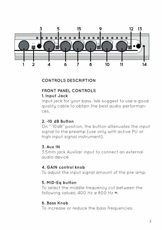
CONTROLS DESCRIPTION FRONT PANEL CONTROLS1. Input JackInput jack for your bass. We suggest to use a good quality cable to obtain the best audio performan-ces.
2. -10 dB ButtonOn “-10dB” position, the button attenuates the input signal to the preamp (use only with active PU or high input signal instrument).
3. Aux IN3.5mm jack Auxiliar input to connect an external audio device
4. GAIN control knob To adjust the input signal amount of the pre-amp.
5. MID-Eq button To select the middle frequency cut between the following values: 400 Hz e 800 Hz ≈.
6. Bass Knob To increase or reduce the bass frequencies.
6
7. Mid knob To increase or reduce the mid range frequencies.
8. High knobTo increase or reduce the high frequencies.
9. SUBS Filter button Subsonic filter switcher for the woofer protection. The subsonic filter eliminates the frequencies under 22Hz. It does not modify the audio signal and redu-ces the woofer range.
10. DI-HEAR KNOB DI and headphones volume. The headphones volu-me is amplified compared to the DI. Even if you put on the minimum level, the audio signal is still on in the headphones although it is very low.
11. Master knob Master volume of the amplifier.
12. Mute buttonTurn off the amplifier output. The activation of this mode turns on the red LED on the left of the button. The tuner-out is still on.
13. Hear output 3.5mm plug for headphones.
14. Operation LED Green = normal operation. Orange = high level of the input signal (clip).
15. Vu-MeterA 20 LED bar indicates the audio signal pitch.
7
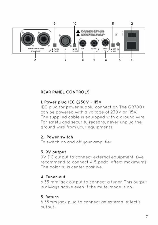
REAR PANEL CONTROLS
1. Power plug IEC (230V - 115V IEC plug for power supply connection The GR700+ can be powered with a voltage of 230V or 115V. The supplied cable is equipped with a ground wire. For safety and security reasons, never unplug the ground wire from your equipments.
2. Power switch To switch on and off your amplifier.
3. 9V output9V DC output to connect external equipment (we recommend to connect 4-5 pedal effect maximum). The polarity is center positive.
4. Tuner-out6.35 mm jack output to connect a tuner. This output is always active even if the mute-mode is on.
5. Return6.35mm jack plug to connect an external effect’s output.
8
6. Send6.35mm jack plug to connect an external effect’s input
7. DI outputXLR plug
8. Speakon outputs It is possible to use a 6.35 mm jack. We recommend to use a 2 poles speakon connector Never use a 6.35 jack guitar cable to connect your amplifier to your speakers.
9. FAN switch FAN cooler on and off switch We recommend to switch off the FAN only at home or in a recording studio. The failure of the fan’s activation ONLY determines the heating of the GR700+ case, which is actually a heat sink. The case increases its own temperature and decreases the internal electronics. The failure of the fan’s activation and prolonged use in extreme weather conditions could activate the overheating protection system of the GR700+. In this unlikely case, please activate the fan and wait few seconds until the amplifier come back to the normal working status.
10. PRE-POST DI buttonAllows you to choose the type of signal to be sent to the DI output DI: PRE EQ or POST EQ.
9
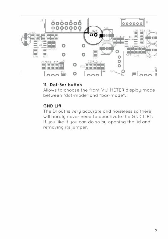
11. Dot-Bar button Allows to choose the front VU-METER display mode between “dot-mode” and “bar-mode”.
GND LiftThe DI out is very accurate and noiseless so there will hardly never need to deactivate the GND LIFT. If you like it you can do so by opening the lid and removing its jumper.
10
WARRANTY CONDITION
The warranty covers a period of two years. The warranty covers any defects in material or wor-kmanship under normal use during the warranty period. Any shipping cost to/from the repair service centre is the customer’s responsibility. In the event of an irreparable damage or repeated failure of the same type, the manufacturer may replace the unit, within the term of the original warranty. The war-ranty does not cover parts which may result faulty due to: - Negligence or careless use - Improper installation and maintenance - Tampering made by unauthorized personnel. - Damages that might not be related to manufacturing defects. The manufacturer accepts no responsibility for any damage due to persons, animals or things, as con-sequence of the failure to comply all the installation requirements and / or use indicated in this user manual.
11
Note

via Nino Bixio 182 70043 Monopoli (Ba) > tel.: 347 6322 [email protected] > www.grbass.com > P.IVA: 07558880725