Embed Size (px)
Citation preview
1
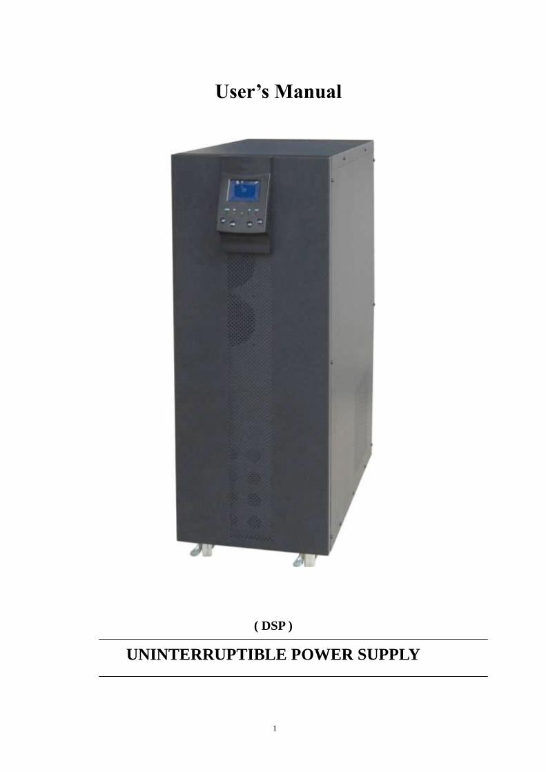
User’s Manual
( DSP )
UNINTERRUPTIBLE POWER SUPPLY

2
Caution
Please strictly comply with the manual operation instruction, and keep the
manual well. Make sure read the manual carefully before use!
Non-professional technicians are prohibited to open the unit casing in case of
electric shock, as the input and output of the unit have high voltage, it may endanger
your safety.
Make sure the units connect with ground well when installing.
Close up all switches for 5 minutes before opening the unit casing for
maintenance.
Do not touch the electrolyte flooded from the damaged battery, as the
electrolyte is corrosive.
The unit battery should keep same brand and same type. Forbid mixed-using
different battery from different manufacturers.
The unit is class “A” product; it may cause radio interference on environment.
Do not try to change the unit configuration; it may affect the unit performance.
Operate the unit within the specified voltage range. Prevent unit from insulation,
drenching or shaking.
Do not install the unit in the environment of flammability, explicability or
corrosiveness and electric dust.
Only professionals can installs and maintain the unit.
3
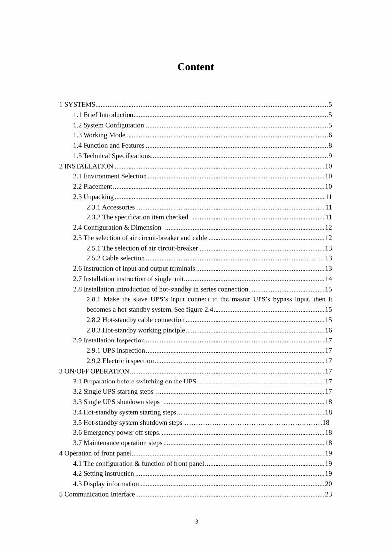
Content
1 SYSTEMS...................................................................................................................................... 5
1.1 Brief Introduction ................................................................................................................ 5
1.2 System Configuration ......................................................................................................... 5
1.3 Working Mode .................................................................................................................... 6
1.4 Function and Features ......................................................................................................... 8
1.5 Technical Specifications ...................................................................................................... 9
2 INSTALLATION ......................................................................................................................... 10
2.1 Environment Selection ...................................................................................................... 10
2.2 Placement .......................................................................................................................... 10
2.3 Unpacking ......................................................................................................................... 11
2.3.1 Accessories ............................................................................................................. 11
2.3.2 The specification item checked ............................................................................ 11
2.4 Configuration & Dimension ............................................................................................ 12
2.5 The selection of air circuit-breaker and cable ................................................................... 12
2.5.1 The selection of air circuit-breaker ........................................................................ 13
2.5.2 Cable selection ........................................................................................... ………13
2.6 Instruction of input and output terminals .......................................................................... 13
2.7 Installation instruction of single unit ................................................................................. 14
2.8 Installation introduction of hot-standby in series connection............................................ 15
2.8.1 Make the slave UPS’s input connect to the master UPS’s bypass input, then it
becomes a hot-standby system. See figure 2.4 ................................................................ 15
2.8.2 Hot-standby cable connection ................................................................................ 15
2.8.3 Hot-standby working pinciple ................................................................................ 16
2.9 Installation Inspection ....................................................................................................... 17
2.9.1 UPS inspection ....................................................................................................... 17
2.9.2 Electric inspection .................................................................................................. 17
3 ON/OFF OPERATION ................................................................................................................ 17
3.1 Preparation before switching on the UPS ......................................................................... 17
3.2 Single UPS starting steps . ................................................................................................ 17
3.3 Single UPS shutdown steps ............................................................................................. 18
3.4 Hot-standby system starting steps ..................................................................................... 18
3.5 Hot-standby system shutdown steps ……………………………………………………18
3.6 Emergency power off steps. .............................................................................................. 18
3.7 Maintenance operation steps ............................................................................................. 18
4 Operation of front panel ............................................................................................................... 19
4.1 The configuration & function of front panel ..................................................................... 19
4.2 Setting instruction ............................................................................................................. 19
4.3 Display information .......................................................................................................... 20
5 Communication Interface ............................................................................................................. 23
4
5.1 RS232 instruction .............................................................................................................. 23
5.2 RS485 Instruction ............................................................................................................. 23
5.3 USB instruction: ................................................................................................................ 24
5.4 Dry-Contact instruction ..................................................................................................... 24
5.5 SNMP instruction .............................................................................................................. 24
5.6 EPO interface .................................................................................................................... 24
6 Daily Maintenance ....................................................................................................................... 24
6.1 Battery use and maintenance ............................................................................................. 24
6.2 UPS maintenance .............................................................................................................. 25
6.3 Maintenance safeguard...................................................................................................... 25
6.4 Trouble shooting ............................................................................................................... 25
6.5 Package, shippment and storage. ...................................................................................... 26
6.5.1 Package .................................................................................................................. 26
6.5.2 Shippment .............................................................................................................. 26
6.5.3 Storage ................................................................................................................... 27
5
1 SYSTEMS
1.1 BRIEF INTRODUCTION
DSP series UPS are mainly applied to computers, data center, and administration
center of networks, precision instruments ect. Providing high reliable AC uninterruptible
power supply.
The UPS, equipped with dual-conversion design with output isolation transformer
and advanced complete digital control technology, keep on providing the load with clean
uninterruptible power with stable voltage and frequency when the mains off.
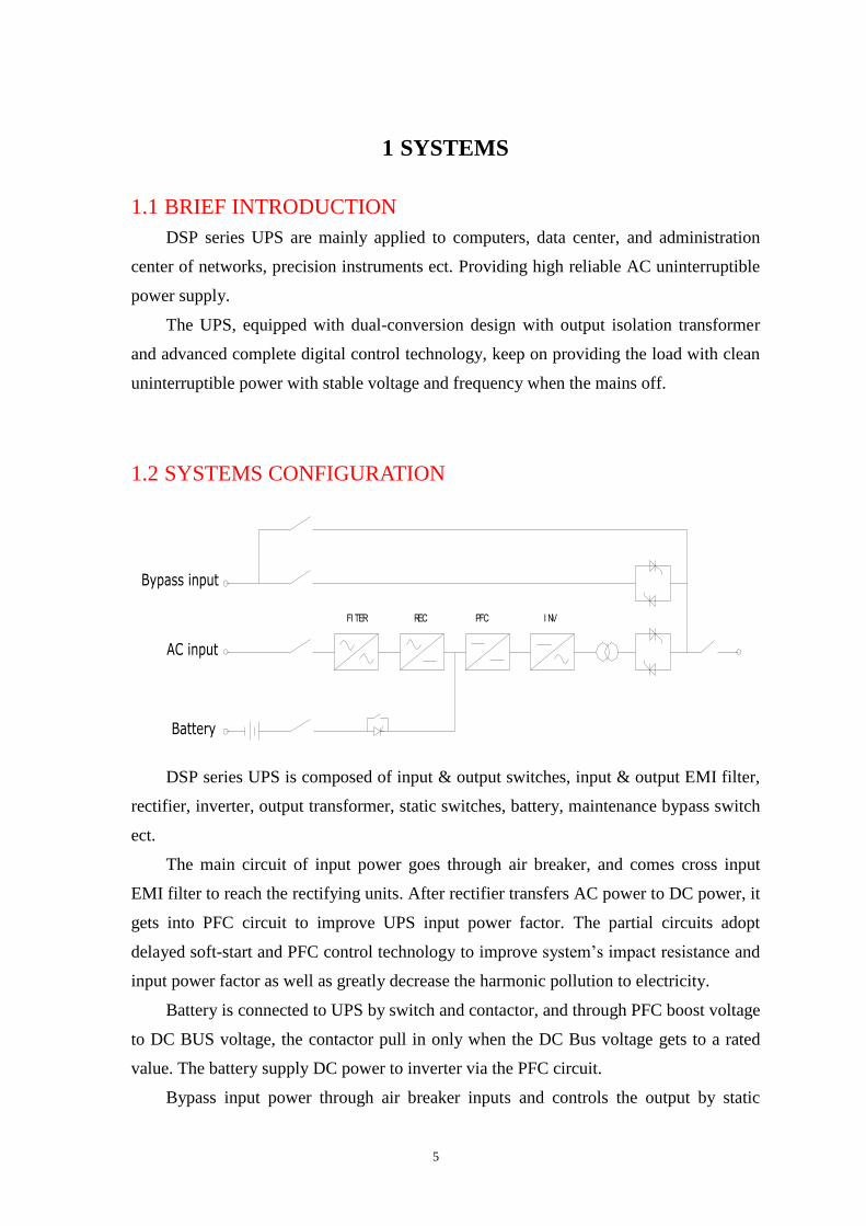
1.2 SYSTEMS CONFIGURATION
I NVPFCRECFI TER
Bypass input
AC input
Battery
DSP series UPS is composed of input & output switches, input & output EMI filter,
rectifier, inverter, output transformer, static switches, battery, maintenance bypass switch
ect.
The main circuit of input power goes through air breaker, and comes cross input
EMI filter to reach the rectifying units. After rectifier transfers AC power to DC power, it
gets into PFC circuit to improve UPS input power factor. The partial circuits adopt
delayed soft-start and PFC control technology to improve system’s impact resistance and
input power factor as well as greatly decrease the harmonic pollution to electricity.
Battery is connected to UPS by switch and contactor, and through PFC boost voltage
to DC BUS voltage, the contactor pull in only when the DC Bus voltage gets to a rated
value. The battery supply DC power to inverter via the PFC circuit.
Bypass input power through air breaker inputs and controls the output by static
6
bypass switch.
The whole system completely adopts digital DSP control. All of UPS inverter
control, phase synchronization, input rectifier control and logic control ect adopt DSP
digital signal manager, which has high precision, fast speed, easy circuit and high
reliability.
The system has the following working modes.
1.3 Working Mode
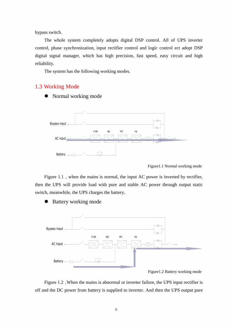
Normal working mode
I NVPFCRECFI TER
Bypass input
AC input
Battery
Figure1.1 Normal working mode
Figure 1.1,when the mains is normal, the input AC power is inverted by rectifier,
then the UPS will provide load with pure and stable AC power through output static
switch, meanwhile, the UPS charges the battery.
Battery working mode
I NVPFCRECFI TER
Bypass input
AC input
Battery
Figure1.2 Battery working mode
Figure 1.2,When the mains is abnormal or inverter failure, the UPS input rectifier is
off and the DC power from battery is supplied to inverter. And then the UPS output pure
7
and stable AC power to load through static switch. At this time, UPS stops charging the
battery.
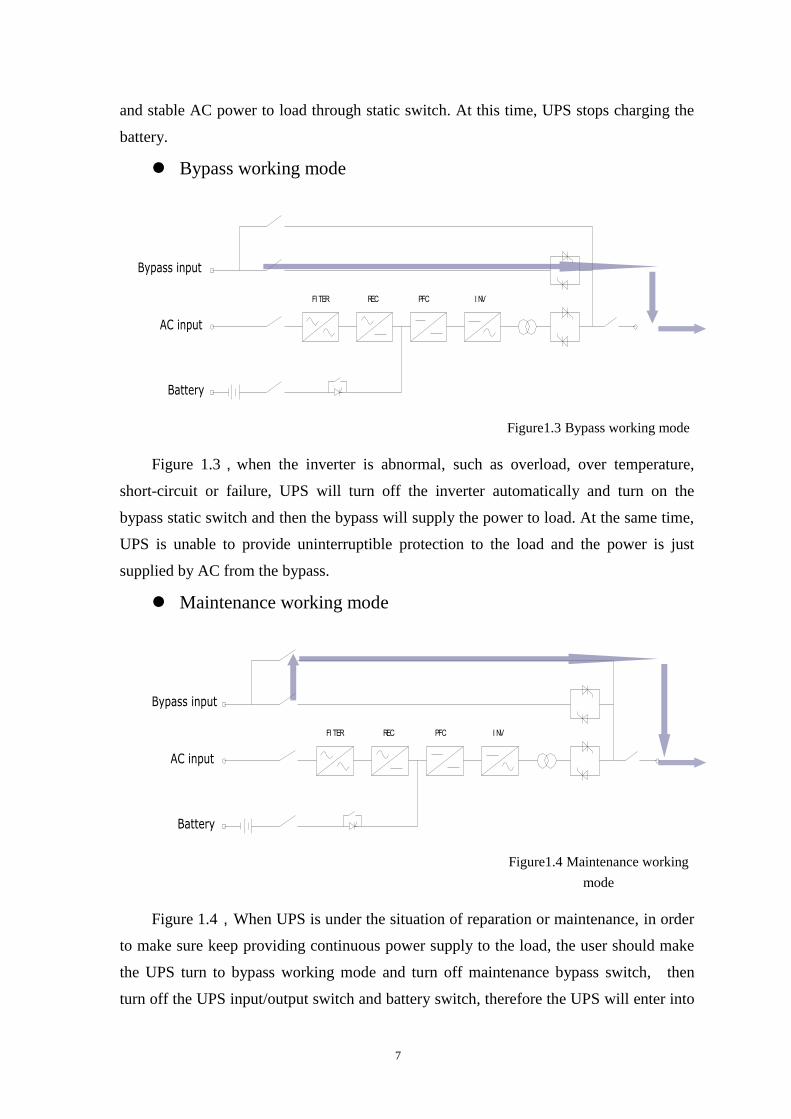
Bypass working mode
I NVPFCRECFI TER
Bypass input
Battery
AC input
Figure1.3 Bypass working mode
Figure 1.3,when the inverter is abnormal, such as overload, over temperature,
short-circuit or failure, UPS will turn off the inverter automatically and turn on the
bypass static switch and then the bypass will supply the power to load. At the same time,
UPS is unable to provide uninterruptible protection to the load and the power is just
supplied by AC from the bypass.
Maintenance working mode
I NVPFCRECFI TER
Battery
AC input
Bypass input
Figure1.4 Maintenance working
mode
Figure 1.4,When UPS is under the situation of reparation or maintenance, in order
to make sure keep providing continuous power supply to the load, the user should make
the UPS turn to bypass working mode and turn off maintenance bypass switch, then
turn off the UPS input/output switch and battery switch, therefore the UPS will enter into
8
maintenance mode, shows as the arrow indicated in the figure. It is safe to repair the UPS
as there is no electricity in the inner UPS at this time.
1.4 Function and Features
1.Advanced DSP digital control technology
the inverter control, phase synchronization, input rectifier control, logic control ect… all
adopts DSP digit signal technology with high precision, high speed, high reliability.
2. High input power factor, green energy-saving power
Input power factor reaches up to more than 0.98; the total harmonic distortion of
input current THDI<5%; it greatly decreases distortion pollution from UPS to the
electricity , increase the mains usage and reduce installation cost.
3. Wide input voltage and frequency range
Wide input voltage and frequency range can decrease battery’s frequent charging
time, make good use of battery. It also has strong ability to adapt electricity so that the
motor can be easily connected.
4. Abundant interface setting function
Through the buttons on the front panel, the user can set up output voltage and rated
frequency, so that the UPS can be applied to different voltage and frequency.
5. Excellent network monitor function
Provide with RS232, RS485, SNMP, USB, dry contact interface, support TCP/IP
protocol. The user can monitor UPS working status on-line neglecting the distance, and
make the UPS execute self-test procedure, time sending inquiry, send E-MAIL, as well as
automatically save computer data and turn off the computer safely.
6. Big LCD display
There is an option for user to choose the Chinese or English LCD display, it can
display the UPS working parameter and status, faults alarming information and history
records, it is very convenient for daily management and maintenance.
7. Perfect protection
UPS has input low / over voltage protection, output low / over voltage protection,
overload protection, short-circuit protection, overheat protection; ECO protection, surge
protection ect. it can make sure that the UPS can work well under different environment.
8. Cold start and AC start function
When there are no mains, UPS can start by the battery; or when there is no battery,
UPS can start by the mains. To meet user’s needs, when the battery is discharging to
9
low-voltage protection, it can automatically start the UPS when the mains recover.
9. Easy for maintenance
Designed with manual bypass maintenance, the load can still have power supply when
the UPS is in maintenance, it is convenient for users, and it also improves usability and
maintainability of the system.
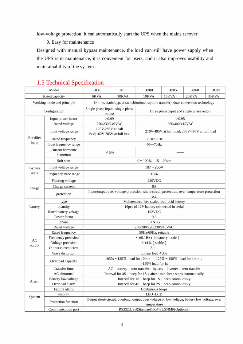
1.5 Technical Specification Model 8806 8810 38810 38815 38820 38830
Rated capacity 6KVA 10KVA 10KVA 15KVA 20KVA 30KVA
Working mode and principle Online, static bypass switch(uninterruptible transfer), dual-conversion technology
Configuration Single phase input , single phase
output Three phase input and single phase output
Rectifier
input
Input power factor >0.99 >0.95
Rated voltage 220/230/240VAC 380/400/415VAC
Input voltage range 120V-285V at half
load;160V-285V at full load 210V-495V at half load; 280V-495V at full load
Rated frequency 50Hz/60Hz
Input frequency range 40—70Hz
Current harmonic
distortion <5% ——
Soft start 0~100% 15—20sec
Bypass
input
Input voltage range 187~253V
Frequency trace range ±5%
charge
Floating voltage 220VDC
Charge current 8A
protection Input/output over voltage protection, short-circuit protection, over temperature protection
ect.
battery
type Maintenance-free sealed lead-acid battery
quantity 16pcs of 12V battery connected in serial
Rated battery voltage 192VDC
AC
output
Power factor 0.8
phase L+N+G
Rated voltage 200/208/220/230/240VAC
Rated frequency 50Hz/60Hz, settable
Frequency precision <±0.1Hz(in battery mode)
Voltage precision <±1%(stable)
Output current crest 3:1
Wave distortion Linear load<3%
Overload capacity 105%~125% load for 10min ;125%~150% load for 1min;
>150% load for 1s
Transfer time AC—battery:zero transfer;bypass—inverter:zero transfer
Alarm
AC abnormal Interval for 4S,beep for 1S;after 1min, beep stops automatically
Battery low voltage Interval for 1S,beep for 1S;beep continuously
Overload alarm Interval for 4S,beep for 2S;beep continuously
Failure alarm Continuous beeps
System
display LED+LCD
Protection function Output short-circuit, overload, output over voltage or low voltage, battery low voltage, over
temperature
Communication port RS232,USB(Standard),RS485,SNMP(Optional)
10
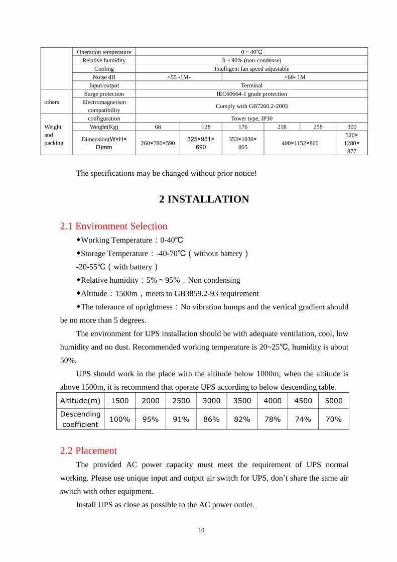
Operation temperature 0~40℃
Relative humidity 0~90% (non-condense)
Cooling Intelligent fan speed adjustable
Noise dB <55 -1M- <60- 1M
Input/output Terminal
others
Surge protection IEC60664-1 grade protection
Electromagnetism
compatibility Comply with GB7260.2-2003
Weight
and
packing
configuration Tower type, IP30
Weight(Kg) 68 128 176 218 258 300
Dimension(W×H×
D)mm 260×780×590
325×951×
690
353×1030×
805 400×1152×860
520×
1280×
877
The specifications may be changed without prior notice!
2 INSTALLATION
2.1 Environment Selection
◆Working Temperature:0-40℃
◆Storage Temperature:-40-70℃(without battery)
-20-55℃(with battery)
◆Relative humidity:5%~95%,Non condensing
◆Altitude:1500m,meets to GB3859.2-93 requirement
◆The tolerance of uprightness:No vibration bumps and the vertical gradient should
be no more than 5 degrees.
The environment for UPS installation should be with adequate ventilation, cool, low
humidity and no dust. Recommended working temperature is 20~25℃, humidity is about
50%.
UPS should work in the place with the altitude below 1000m; when the altitude is
above 1500m, it is recommend that operate UPS according to below descending table.
Altitude(m) 1500 2000 2500 3000 3500 4000 4500 5000
Descending
coefficient 100% 95% 91% 86% 82% 78% 74% 70%
2.2 Placement
The provided AC power capacity must meet the requirement of UPS normal
working. Please use unique input and output air switch for UPS, don’t share the same air
switch with other equipment.
Install UPS as close as possible to the AC power outlet.

11
The floor board which takes the UPS weight should be strong enough. Any other
dangerous installation is forbidden.
No storage of flammable, explosive and other dangerous goods in the place and fire
equipment is required.
Keep good ventilation around UPS, don’t obstruct the cooling channels.
Keep each side of the UPS at least 1 meter away from the wall so that there should
be enough space for future maintenance and operation.
It is recommended that there should be a professional for UPS house management,
non-professional is forbidden to enter in.
2.3 Unpacking
Before unpacking, inspect if the packaging is damaged during the transport and if it
is the correct model you ordered. After unpacking, check if all the accessories are
included and if the real product is right.
2.3.1 Accessories
User manual, 1pc;
CD for monitoring software, 1pc;
Cables for RS232 and USB interface, each 1pc;
2.3.2 The items of UPS specification should be checked
UPS Capacity;the voltage of input and output、frequency;the phase of input and
output;Battery voltage.
12
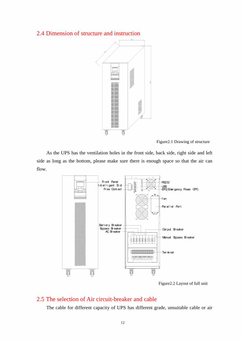
2.4 Dimension of structure and instruction
ENTER
ON/ OFF
SCREEN
ESC
LI NE BYPASS BAT. I NV. FAULT
Figure2.1 Drawing of structure
As the UPS has the ventilation holes in the front side, back side, right side and left
side as long as the bottom, please make sure there is enough space so that the air can
flow.
RS232
USBEPO( Emer gency Power OFF)
f an
Par al l el Por t
Out put Br eaker
Manual Bypass Br eaker
AC Br eakerBypass Br eaker
Bat t er y Br eaker
I nt el l i gent Sl otFr ont Panel
PARALLEL PORT
SI NGLE MODE
INTELLIGENT SLOT
RS232
USB
485-485+
GND
EPO.
FAULT
OVER LOAD
BYPASS
AC FAULT
BAT. LOW
PARALLEL PORT
SI NGLE MODE
INTELLIGENT SLOT
RS232
USB
485-485+
GND
EPO.
FAULT
OVER LOAD
BYPASS
AC FAULT
BAT. LOW
I NPUT
NLJP2JP1N L
OUTPUTBYPASS
E
PE
E
PE BATTERY
+ -
ENTER
ON/ OFF
SCREEN
ESC
LI NE BYPASS BAT. I NV. FAULT Fr ee Cont act
Ter mi nal
Figure2.2 Layout of full unit
2.5 The selection of Air circuit-breaker and cable
The cable for different capacity of UPS has different grade, unsuitable cable or air
13
circuit-breaker will cause dangers. The selection principle is: 3-5A/mm2 for middle and
small size UPS, 2.5-3A/mm2 for big power UPS. Meanwhile, note that the maximum
voltage for the power cable not more than 3V is better.
There are input neutral wire for bypass and output neutral wire for UPS power
system. For three phases in and one phase out UPS, the cross-sectional area of input null
line should be 1.5-1.7 times of phase line.
UPS system has safe protection for grounding and lightning protection, their
cross-sectional area should be 0.5-1.0 times of phase line and no smaller than 6mm2
2.5.1 The selection of air circuit-breaker
POWER
KVA
Input voltage
VAC
Output voltage
VAC
Input
Max.current(A)
Output
Max.current(A)
Input air
switch (A)
Output air
switch (A)
4 220 220 32 18 50 32
6 220 220 44 27 63 40
8 220 220 55 36 80 50
10 220/380 220 66 45 100 63
15 380 220 94 68 125 100
20 380 220 122 90 150 125
30 380 220 177 136 200 160
Note: Forbid using creepage protection type switch
2.5.2 Cable selection
Model
4KVA 6KVA 8KVA 10KV
A
10KVA(3:
1)
15KVA(3:
1)
20KVA(3:
1)
30KVA(3:
1)
Wire
mm2
Wire
mm2
Wire
mm2
Wire
mm2
Wire
mm2
Wire
mm2
Wire
mm2
Wire
Mm2
Input 6 8 10 16 6 6 8 16
By-pas
s
6 6 8 10 10 16 25 35
Output 6 6 8 10 10 16 25 35
Battery 6 8 10 10 10 16 25 35
Neutral 6 8 10 16 10 16 25 35
Earthin
g
6 6 6 6 6 6 6 8
Note:The real cable should be no smaller than the figures in above table
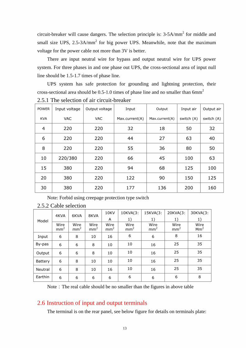
2.6 Instruction of input and output terminals
The terminal is on the rear panel, see below figure for details on terminals plate:
14
NLJP2JP1N L EE + -
I NPUT OUTPUTBYPASS PEPE BATTERY
Figure2.3 Single phase 4~10K
terminal drawing
Figure2.4 three phase in one
phase 10K/15K/20K out terminal
drawing
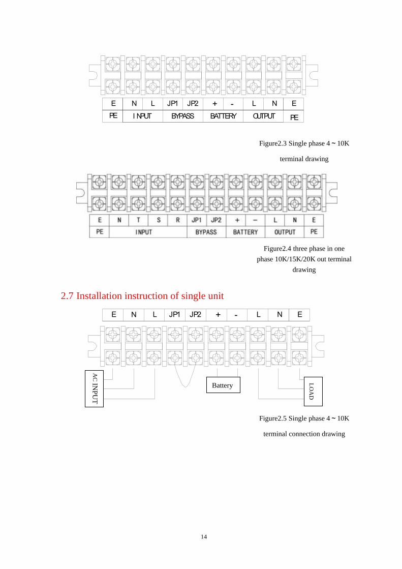
2.7 Installation instruction of single unit
E L -+ EN JP1 JP2 L N
Figure2.5 Single phase 4~10K
terminal connection drawing
AC
INP
UT
LO
AD
Battery
15
Figure2.6 three phase in one
phase out 10K/15K/20K terminal
connection drawing
1)JP1, JP2 must be short connected with 10mm2
wire when operate a single UPS.
2)Anode, cathode of battery and live wire, neutral wire cannot be connected in reverse.
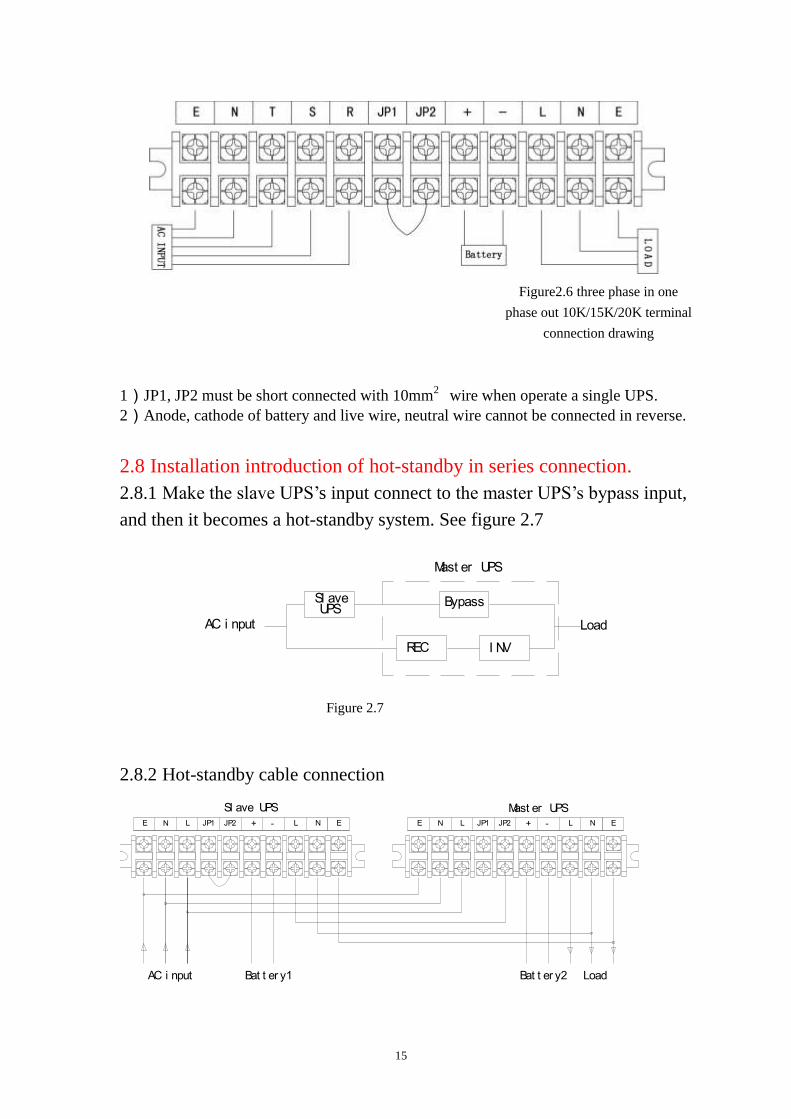
2.8 Installation introduction of hot-standby in series connection.
2.8.1 Make the slave UPS’s input connect to the master UPS’s bypass input,
and then it becomes a hot-standby system. See figure 2.7
Mast er UPS
AC i nput Load
I NVREC
BypassUPS
Sl ave
Figure 2.7
2.8.2 Hot-standby cable connection
NLJP2JP1N E+ -LEE L -+ EN JP1 JP2 L N
Sl ave UPS Mast er UPS
AC i nput Bat t er y1 Bat t er y2 Load
16
Figure 2.8 Single phase hot-standby connection diagram
Figure 2.9 Three phase hot-standby connection diagram
Connect the neutral, line, earth of the mater and slave in parallel, and make the
output line of slave connected to input of the master(JP2)(JP2), and output neutral and
earth in parallel, and loads will be at the output of the master.
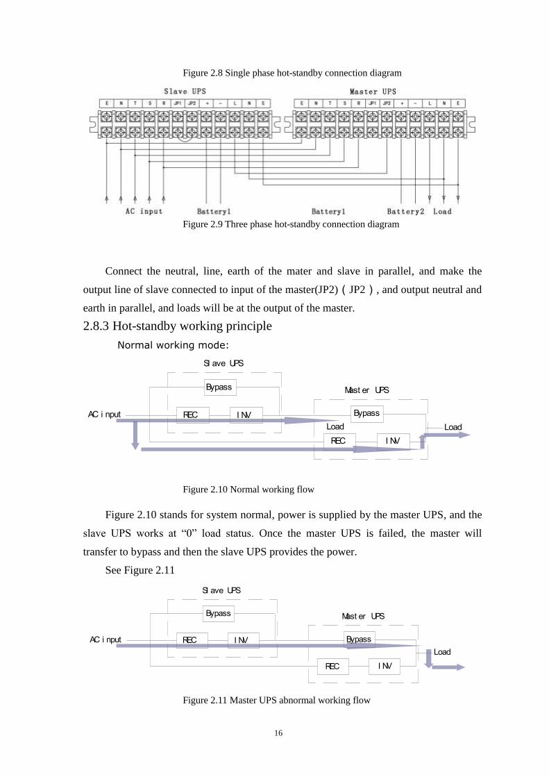
2.8.3 Hot-standby working principle
Normal working mode:
Mast er UPS
Sl ave UPS
Load
AC i nput REC
REC
I NV
I NV
Bypass
Bypass
Load
Figure 2.10 Normal working flow
Figure 2.10 stands for system normal, power is supplied by the master UPS, and the
slave UPS works at “0” load status. Once the master UPS is failed, the master will
transfer to bypass and then the slave UPS provides the power.
See Figure 2.11
Load
Sl ave UPS
Mast er UPS
AC i nput REC I NV
Bypass
Bypass
REC I NV
Figure 2.11 Master UPS abnormal working flow
17
2.9 Installation inspection
2.9.1 UPS Inspection
After UPS installation, please do the necessary inspections as below:
Whether the UPS trucke brake fixed or steady or skew.
Whether the UPS scraped or hit damage.
Whether there are sundries around the UPS body or around it.
2.9.2 Electric inspection
After UPS switching finished, please inspect following items:
The input and output switching is ok and the in and out terminals are canonical
Make sure the input and output connected cable steady,phase series correct and
mark complete.
Make sure battery cable connection fastened, polarity normal and battery setted
steady.
Make sure the cable laying of system canonical, neat and easy for future inspection
and extendable.
3 ON/OFF OPERATION
3.1 Preparation before switching on the UPS
Reconfirm if all connection and power supply are correct before start-up.
Inspect the input voltage and frequency is within the range.
All UPS switches are at off mode.
3.2 Single UPS Starting steps
Turn on the AC input switch. Then the power supply board starts to work and the
LCD will display “LINE and “BAT” lights on, reminding to select the language and
going into standby status.
Turn on battery switch and UPS recharges the batteries with small current.
1) UPS Starting Long press ON/OFF button above 1second, LCD display “starting
in process,please wait…”, about 10seconds later on, UPS transfer to inverter output and
“INV” light on, “BAT ”off.
2) Turn on bypass switch.
3) Turn on output switch.
18
3.3 Single UPS shutdown steps
1) Shut off output switch.
2) Shut off the UPS. Long press ON/OFF button above 1second.
3) Shut off battery switch.
4) Shut off bypass.
5) Shut off AC input switch
3.4 Hot-standby system starting steps
Firstly start the slave UPS( the Standby UPS). Starting steps as same as single
UPS.
Then turn on the master UPS. Starting steps as same as single UPS.
3.5 Hot-standby system shutdown steps
●Turn off the master first. Turn off steps as same as single UPS.
●Then turn off the slave UPS. Turn off steps as same as single UPS.
3.6 Emergency power off steps
When meet emergency affairs, users should shut off all power supply at once and
shut down all the switches at the same time.
3.7 Maintenance operation steps
This step must be done by professional people.
Turn off the inverter. Press the ON/OFF longer than 1 second, and UPS will transfer
to bypass and the bypass light will illumine.
1) Open the rear cover board of the breaker; turn on the manual bypass breaker.
2) Shut off UPS input switch, battery switch, bypass switch and output switch.
3) Do UPS maintenance
4) Turn on the output switch.
5) Turn on the bypass switch, input switch, battery switch and bypass light will be
on.
6) Shut off manual maintenance switch.
7) Switch on the inverter. Press the ON/OFF longer than 1 second, and 10s later,
UPS goes into normal working status.
19
4 Operation of front panel
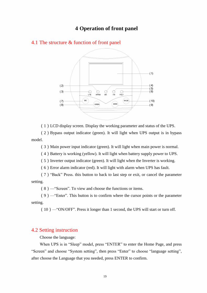
4.1 The structure & function of front panel
( 2)
( 3)
( 7)
( 8) ( 9)
( 10)
( 6)( 5)( 4)
( 1)
FAULTI NV.BAT.BYPASSLI NE
ESC
SCREEN
ON/ OFF
ENTER
(1)LCD display screen. Display the working parameter and status of the UPS.
(2)Bypass output indicator (green). It will light when UPS output is in bypass
model.
(3)Main power input indicator (green). It will light when main power is normal.
(4)Battery is working (yellow). It will light when battery supply power to UPS.
(5)Inverter output indicator (green). It will light when the Inverter is working.
(6)Error alarm indicator (red). It will light with alarm when UPS has fault.
(7)“Back” Press. this button to back to last step or exit, or cancel the parameter
setting.
(8)—“Screen”. To view and choose the functions or items.
(9)—“Enter”. This button is to confirm where the cursor points or the parameter
setting.
(10)—“ON/OFF”. Press it longer than 1 second, the UPS will start or turn off.
4.2 Setting instruction
Choose the language:
When UPS is in “Sleep” model, press “ENTER” to enter the Home Page, and press
“Screen” and choose “System setting”, then press “Enter” to choose “language setting”,
after choose the Language that you needed, press ENTER to confirm.
20
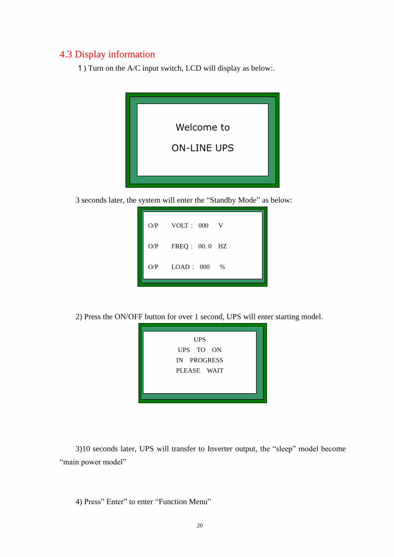
4.3 Display information
1) Turn on the A/C input switch, LCD will display as below:.
易
易 易
易
易
易
易 易 易
易 易易 易
E GA S R POT U
3 seconds later, the system will enter the “Standby Mode” as below:
:
:
:
:
0 0 0 V
0 0 . 0 H Z
0 0 0 %
O / P V O L T
O / P F R E Q
O / P LO A
MO D E
D
S T A N D B Y
2) Press the ON/OFF button for over 1 second, UPS will enter starting model.
E UA S P ST
U OP S O NT
I ON P R ER G S S . .
P EL A WASE I T
3)10 seconds later, UPS will transfer to Inverter output, the “sleep” model become
“main power model”
4) Press” Enter” to enter “Function Menu”
Welcome to
ON-LINE UPS
O/P VOLT: 000 V
O/P FREQ: 00. 0 HZ
O/P LOAD: 000 %
MODE: Standby
UPS
UPS TO ON
IN PROGRESS
PLEASE WAIT
21
S T A T U S
S E T U P
MOD E I N F OL
5) Select “parameter setting” and press “Enter” to check parameters
TATO D AU P U T
I N PU T D A T A
B A T T E R Y D A T A
D C L I N K D A AT
6) Select “output parameter” and press “enter” to check the parameter of output.
:
:
:
0 0 0 V
0 0 . 0 H Z
0 0 0 %
: 0 0 0 A
V O L T A G E
F R E Q
LO A D
C U R R E N T
: 0 0 000
: 0 0 0 0 0
W
VA
WA T T
VA
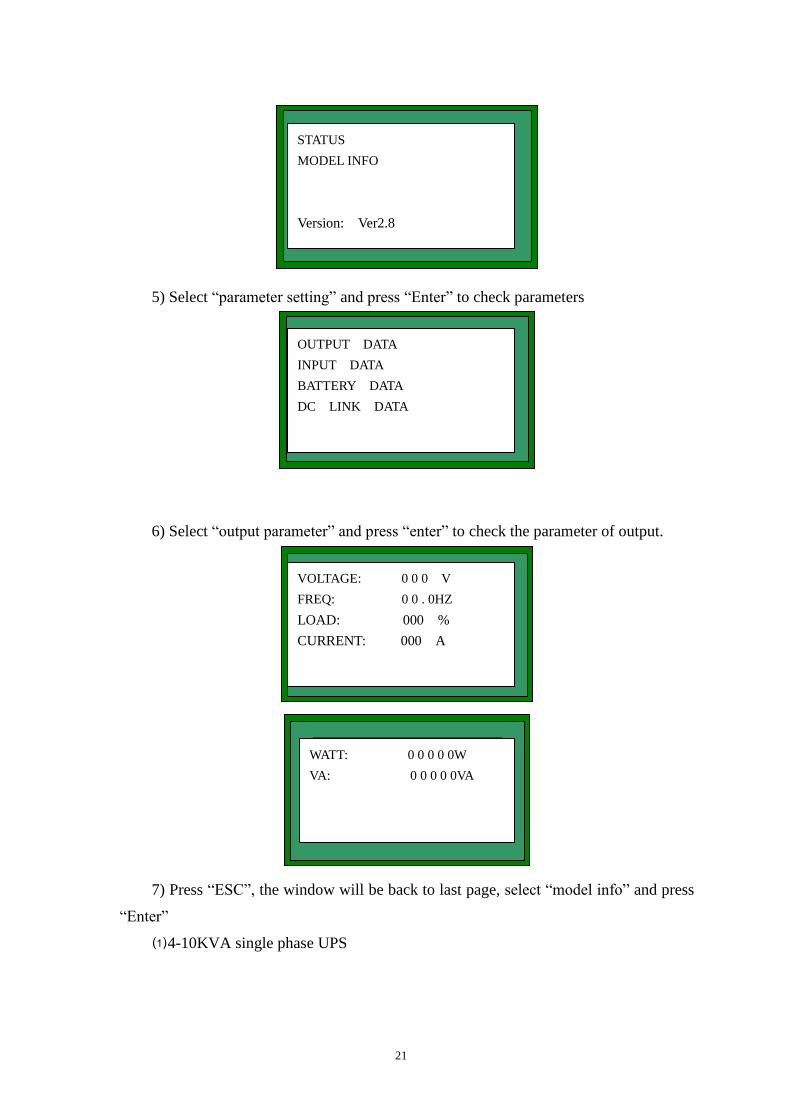
7) Press “ESC”, the window will be back to last page, select “model info” and press
“Enter”
⑴4-10KVA single phase UPS
STATUS
MODEL INFO
Version: Ver2.8
OUTPUT DATA
INPUT DATA
BATTERY DATA
DC LINK DATA
WATT: 0 0 0 0 0W
VA: 0 0 0 0 0VA
VOLTAGE: 0 0 0 V
FREQ: 0 0 . 0HZ
LOAD: 000 %
CURRENT: 000 A
22
:
:
:
0 0 0 V
0 0 . 0 H Z
0 0 0 A
L I N E V O L
F R E Q
C U RR E N T
T
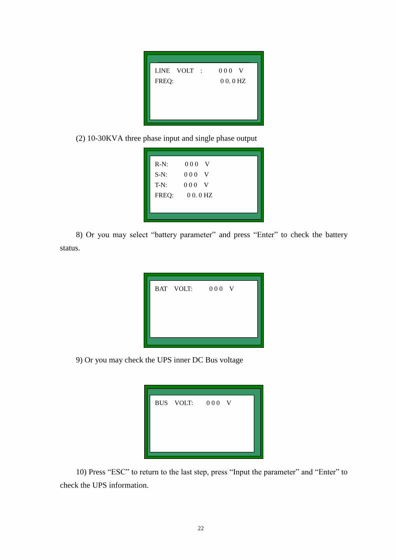
(2) 10-30KVA three phase input and single phase output
:
:
:
0 0 0 V
0 0 . 0 H Z
0 0 0 A
L I N E V O L
F R E Q
C U RR E N T
T
8) Or you may select “battery parameter” and press “Enter” to check the battery
status.
: 0 0 0 VTBA V O L T
9) Or you may check the UPS inner DC Bus voltage
: 0 0 0 VSUB V O LT
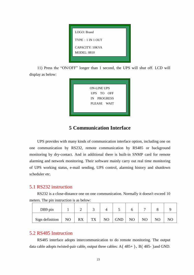
10) Press “ESC” to return to the last step, press “Input the parameter” and “Enter” to
check the UPS information.
LINE VOLT : 0 0 0 V
FREQ: 0 0. 0 HZ
BAT VOLT: 0 0 0 V
BUS VOLT: 0 0 0 V
R-N: 0 0 0 V
S-N: 0 0 0 V
T-N: 0 0 0 V
FREQ: 0 0. 0 HZ
23
:
:
:
0
0E A 88 1
1
T Y P E 1 I N 1 O U T
MO D E L
C A PA C I T Y K VA
11) Press the “ON/OFF” longer than 1 second, the UPS will shut off. LCD will
display as below:
E UA S P ST
U OP S O FT
I ON P R ER G S S . .
P EL A WASE I T
F
5 Communication Interface
UPS provides with many kinds of communication interface option, including one on
one communication by RS232, remote communication by RS485 or background
monitoring by dry-contact. And in additional there is built-in SNMP card for remote
alarming and network monitoring. Their software mainly carry out real time monitoring
of UPS working status, e-mail sending, UPS control, alarming history and shutdown
scheduler etc.
5.1 RS232 instruction
RS232 is a close-distance one on one communication. Normally it doesn't exceed 10
meters. The pin instruction is as below:
DB9 pin 1 2 3 4 5 6 7 8 9
Sign definition NO RX TX NO GND NO NO NO NO
5.2 RS485 Instruction
RS485 interface adopts intercommunication to do remote monitoring. The output
data cable adopts twisted-pair cable, output three cables: A(485+)、B(485-)and GND.
LOGO: Brand
TYPE:1 IN 1 OUT
CAPACITY: 10KVA
MODEL: 8810
ON-LINE UPS
UPS TO OFF
IN PROGRESS
PLEASE WAIT
24
5.3 USB instruction:
EA880 UPS added USB interface as standard matching. It adopts stochastic USB
communication cable to do real time monitoring and management when there is no
RS232 port.
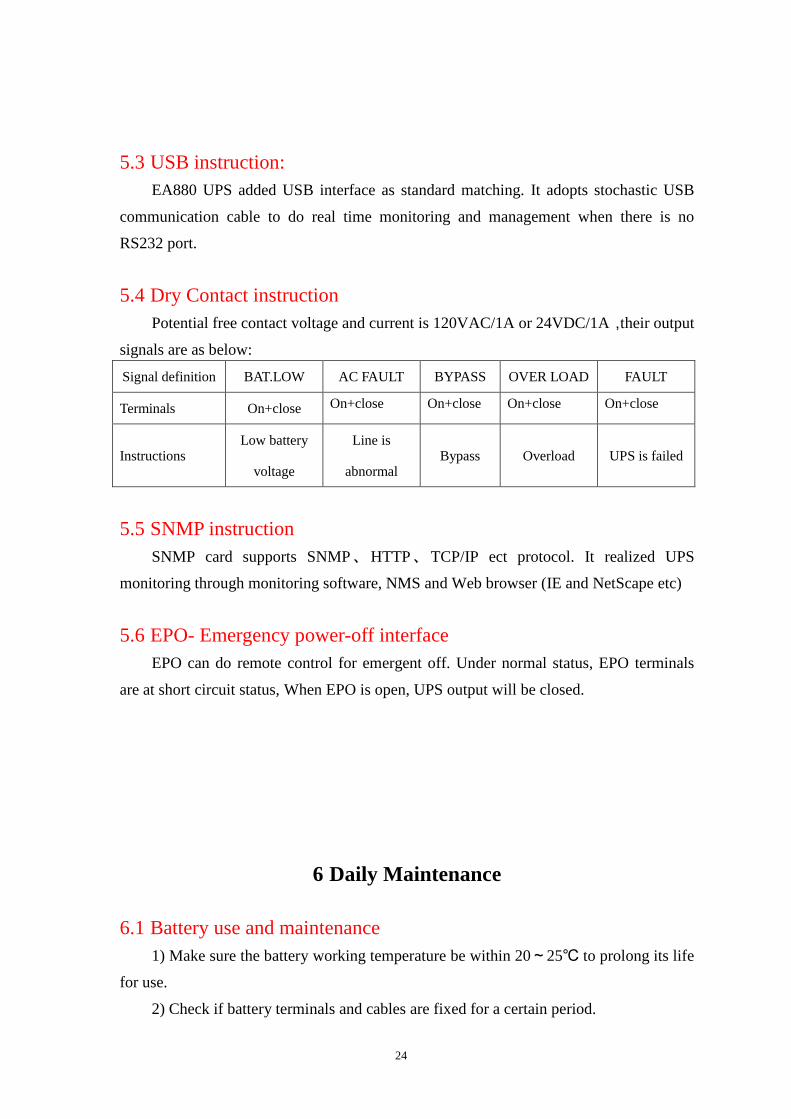
5.4 Dry Contact instruction
Potential free contact voltage and current is 120VAC/1A or 24VDC/1A,their output
signals are as below:
Signal definition BAT.LOW AC FAULT BYPASS OVER LOAD FAULT
Terminals On+close On+close On+close On+close On+close
Instructions Low battery
voltage
Line is
abnormal Bypass Overload UPS is failed
5.5 SNMP instruction
SNMP card supports SNMP、HTTP、TCP/IP ect protocol. It realized UPS
monitoring through monitoring software, NMS and Web browser (IE and NetScape etc)
5.6 EPO- Emergency power-off interface
EPO can do remote control for emergent off. Under normal status, EPO terminals
are at short circuit status, When EPO is open, UPS output will be closed.
6 Daily Maintenance
6.1 Battery use and maintenance
1) Make sure the battery working temperature be within 20~25℃ to prolong its life
for use.
2) Check if battery terminals and cables are fixed for a certain period.
25
3) Clean regularly the dust and white mash on battery to avoid short circuit.
4) Use wet cloth and no solvent when doing cleaning of the battery
5) Check regularly the battery voltage. If it is not abnormal, please change
6) Check regularly if battery are plumped or leaked.
7) Always replace with same brand and same capacity battery.
8) Artificially discharge the battery once time in a certain period ( 4~6 month) if no
stopping of power for a long time, and the discharge capacity within 50% is better.
9) It is not good for battery to discharge at small current. Prevent the small current
from deep discharging to damage the battery.
6.2 UPS maintenance
1) Check regularly the UPS input and output connection.
2) Check regularly if UPS working status is normal or not.
3) Check regularly if UPS heatsink fans are ok or not. And prohibit sundries
stopping vent.
4) Clean regularly the internal dust of UPS. Much dust may cause UPS failure.
6.3 Maintenance safeguard
Right maintenance operation not only makes UPS exert best working status and
prolong its life for use, but also protect the personal safety. Only technicians are approved
for maintenance. And note the followings:
1) Read and know the user manual well before maintenance.
2) Be always on the alert of the UPS internal high voltage. And keep no power
inside the UPS before maintenance.
3) No taking gold, silver jewelry and watch etc before maintenance.
4) Use special tools and testing equipment
5) Make label and records during maintenance.
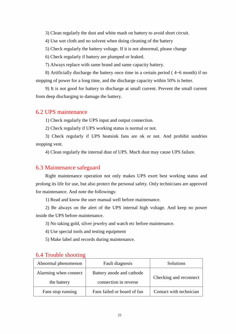
6.4 Trouble shooting
Abnormal phenomenon Fault diagnosis Solutions
Alarming when connect
the battery
Battery anode and cathode
connection in reverse Checking and reconnect
Fans stop running Fans failed or board of fan Contact with technician
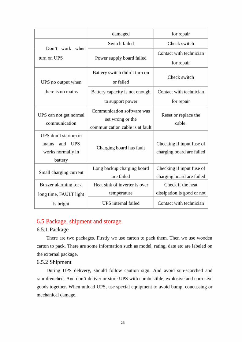
26
damaged for repair
Don’t work when
turn on UPS
Switch failed Check switch
Power supply board failed Contact with technician
for repair
UPS no output when
there is no mains
Battery switch didn’t turn on
or failed Check switch
Battery capacity is not enough
to support power
Contact with technician
for repair
UPS can not get normal
communication
Communication software was
set wrong or the
communication cable is at fault
Reset or replace the
cable.
UPS don’t start up in
mains and UPS
works normally in
battery
Charging board has fault Checking if input fuse of
charging board are failed
Small charging current Long backup charging board
are failed
Checking if input fuse of
charging board are failed
Buzzer alarming for a
long time, FAULT light
is bright
Heat sink of inverter is over
temperature
Check if the heat
dissipation is good or not
UPS internal failed Contact with technician
6.5 Package, shipment and storage.
6.5.1 Package
There are two packages. Firstly we use carton to pack them. Then we use wooden
carton to pack. There are some information such as model, rating, date etc are labeled on
the external package.
6.5.2 Shipment
During UPS delivery, should follow caution sign. And avoid sun-scorched and
rain-drenched. And don’t deliver or store UPS with combustible, explosive and corrosive
goods together. When unload UPS, use special equipment to avoid bump, concussing or
mechanical damage.

27
6.5.3 Storage
UPS should be stored in dry environment. and prohibit from sun-scorched and
rain-drenched. The storage environment temperature is -25~+55℃. The battery storage
temperature is 0~+40℃. And the humidity is 20%~90%. If the battery storage is more
than three months, they should be charged once to prevent it from discharging
automatically and causing damage.