Embed Size (px)
Citation preview
User’s Manual
Intuitive satellite systems analysissoftware designed to assist in
visualizing and analyzing complexrelationships in space systems
VERSION 4.0 FOR ENGINEERINGWORKSTATIONS
AUTHORS: SHEILA R. MARSHALL
RALPH C. PATRICK
ANALYTICAL GRAPHICS, INC.660 American Avenue
King of Prussia, PA 19406
GS01-MO40-AG05-070797
This document and the software described in it are the proprietary and trade-secret information of Analytical Graphics, Incorporated. They are providedunder, and are subject to, the terms and conditions of a written softwarelicense agreement between Analytical Graphics, Incorporated and itscustomer, and may not be transferred, disclosed or otherwise provided tothird parties, unless otherwise permitted by that agreement. Use,reproduction or publication of any portion of this material without the priorwritten authorization of Analytical Graphics, Incorporated is prohibited.
While reasonable efforts have been taken in the preparation of this manual toensure accuracy, Analytical Graphics, Incorporated assumes no liabilityresulting from any errors or omissions in this manual, or from the use of theinformation contained herein.
Copyright © 1997 Analytical Graphics, Incorporated.
All Rights Reserved.
Satellite Tool Kit (STK)® is a registered trademark of Analytical Graphics,Incorporated. The Analytical Graphics name and triangle logo design areregistered trademarks, Reg. U.S. Pat. & Tm. Off.
Restricted Rights Legend (US Department of Defense Users). Use,duplication or disclosure by the Government is subject to restrictions setforth in subparagraph (c)(1)(ii) of the Rights in Technical Data andComputer Software clause at DFARS 252.277-7013.
Analytical Graphics, Incorporated
660 American Avenue
King of Prussia, PA 19406
Restricted Rights Notice (US Government Users excluding DoD).Notwithstanding any other lease or license agreement that may pertain to oraccompany the delivery of this computer software, the rights of theGovernment regarding its use, reproduction and disclosure are set forth inthe Commercial Computer Software Restricted Rights clause at FAR52.227-19(c)(2).
Software License Agreement
Satellite Tool Kit® Software License Agreement
ANALYTICAL GRAPHICS, INC. (AGI) IS WILLING TO LICENSESATELLITE TOOL KIT (STK)® TO YOU ONLY UPON THECONDITION THAT YOU ACCEPT ALL OF THE TERMS IN THISLICENSING AGREEMENT. BEFORE YOU OPEN THEACCOMPANYING SOFTWARE MEDIA, READ THE TERMS ANDCONDITIONS OF THIS LICENSE AGREEMENT CAREFULLY. BYOPENING THE ACCOMPANYING SOFTWARE MEDIA, YOU ARECONSENTING TO BE BOUND BY AND ARE BECOMING A PARTY TOTHIS LICENSE AGREEMENT. IF YOU DO NOT AGREE WITH THETERMS AND CONDITIONS OF THIS AGREEMENT, AGI ISUNWILLING TO LICENSE STK TO YOU, IN WHICH EVENT YOUSHOULD RETURN THE UNOPENED SOFTWARE MEDIA AS WELL ASTHE DOCUMENTATION WITHIN THIRTY (30) DAYS OF PURCHASEAND YOUR LICENSE PRICE WILL BE REFUNDED.
ANALYTICAL GRAPHICS, INC.
SOFTWARE LICENSE AGREEMENT
Analytical Graphics, Inc. (Analytical Graphics) provides the programand manual (the "Software") and licenses its use to you. You assumeresponsibility for the selection of the Software to achieve yourintended results, and for installation, use and results obtained from theSoftware.
1. LICENSE
(1.1) You may: (a) use this Software only on one single computer atany one time (a "computer" being hereby defined as one centralprocessing unit, a single display and associated peripheral equipment,
Software License Agreement
Satellite Tool Kit® Software License Agreement
all at one location); and (b) make one (1) copy of the Software in anymachine in any readable form for backup purposes in support of yourown use of the Software on a single computer.(1.2) You must reproduce and include the copyright and otherproprietary notices of Analytical Graphics on any copy of all or anyportion of the Software, and all such copies shall be subject to all theterms and conditions of the Agreement.
(1.3) YOU MAY NOT USE, COPY, MODIFY OR TRANSFERTHE SOFTWARE OR ANY COPY, MODIFICATION ORMERGED PORTION THEREOF, IN WHOLE OR IN PART,EXCEPT AS EXPRESSLY PROVIDED IN THE AGREEMENT.
2. LIMITATION AND WARRANTIES
(2.1) THE SOFTWARE IS PROVIDED "AS IS" WITHOUT WARRANTYOF ANY KIND, EITHER EXPRESS OR IMPLIED, INCLUDING BUTNOT LIMITED TO THE IMPLIED WARRANTIES OFMERCHANTABILITY AND FITNESS FOR A PARTICULARPURPOSE. YOU ASSUME THE ENTIRE RISK AS TO THE QUALITYAND PERFORMANCE OF THE SOFTWARE. SHOULD THESOFTWARE PROVE DEFECTIVE, YOUR ENTIRE AND EXCLUSIVEREMEDY SHALL BE GOVERNED BY PARAGRAPH 3 HEREOF.
(2.2) SOME STATES DO NOT ALLOW THE EXCLUSION OFIMPLIED WARRANTIES, SO THE ABOVE EXCLUSION MAY NOTAPPLY TO YOU. THIS WARRANTY GIVES YOU SPECIFIC LEGALRIGHTS AND YOU MAY ALSO HAVE OTHER RIGHTS WHICHVARY FROM STATE TO STATE.
(2.3) Analytical Graphics does not warrant that the functions contained inthe Software will be uninterrupted or error free. You are advised to test theSoftware thoroughly before relying on it.

Software License Agreement
Satellite Tool Kit® Software License Agreement
3. LIMITATION OF REMEDIES
(3.1) IN NO EVENT WILL ANALYTICAL GRAPHICS OR ITSSUPPLIERS, DISTRIBUTORS, OR DEALERS BE LIABLE TO YOUFOR ANY DIRECT OR OTHER DAMAGES, INCLUDING ANYLOST PROFITS, LOST SAVINGS OR OTHER INCIDENTAL,SPECIAL OR CONSEQUENTIAL DAMAGES ARISING OUT OFTHE USE OR INABILITY TO USE THE SOFTWARE EVEN IFANALYTICAL GRAPHICS OR ANY AUTHORIZED ANALYTICALGRAPHICS DEALER HAD BEEN ADVISED OF THE POSSIBILITYOF SUCH DAMAGES, NOR SHALL ANALYTICAL GRAPHICS BELIABLE FOR ANY CLAIM BY ANY OTHER PARTY.
(3.2) SOME STATES DO NOT ALLOW THE LIMITATION OREXCLUSION OF LIABILITY FOR INCIDENTAL ORCONSEQUENTIAL DAMAGES SO THE ABOVE LIMITATION OREXCLUSION MAY NOT APPLY TO YOU.
4. TERMINATION
The license granted under this agreement is effective until terminated. Youmay terminate this license at any time by destroying all copies of the softwarein your possession, and providing written notice of such termination anddestruction to Analytical Graphics. The license granted under thisAgreement will terminate if you violate any of the terms and conditions ofthe Agreement. You agree upon such termination to promptly destroy allcopies of the Software in your possession and to certify in writing toAnalytical Graphics that such action has been taken.

Software License Agreement
Satellite Tool Kit® Software License Agreement
5. LAW TO GOVERN
This Agreement shall be governed by the laws of the Commonwealth ofPennsylvania.
6. NO TRANSFER
None of your rights, duties or obligations under this Agreement may be sold,sublicensed, assigned, rented, leased, loaned or otherwise transferred withoutthe prior written consent of Analytical Graphics, and any attempt to so sell,sublicense, assign, rent, lease, loan or transfer without Analytical Graphics'prior written consent is void.
7. YOU ACKNOWLEDGE THAT:
(a) YOU HAVE READ THIS ENTIRE AGREEMENT AND AGREE TOBE BOUND BY ITS TERMS AND CONDITIONS;
(b) THIS AGREEMENT IS THE COMPLETE AND EXCLUSIVESTATEMENT OF THE UNDERSTANDING AND CONTRACTBETWEEN US AND SUPERSEDES ANY AND ALL PRIOR ORAL ORWRITTEN COMMUNICATIONS RELATING TO THE SUBJECTMATTER HEREOF; AND
(c) THIS AGREEMENT MAY NOT BE MODIFIED, AMENDED ORIN ANY WAY ALTERED EXCEPT BY A WRITTEN AGREEMENTSIGNED BY BOTH YOU AND ANALYTICAL GRAPHICS.
Software License Agreement
Satellite Tool Kit® Software License Agreement
8. NOTICES
Any notices regarding this agreement shall be sent to:
Analytical Graphics, Inc.660 American Avenue, Suite 200King of Prussia, PA 19406
9. ACCEPTANCE
By opening the accompanying software media, you agree to all of the termsof this license Agreement. If you do not agree to these license terms andconditions, return the software within thirty (30) days of purchase for arefund of the purchase price.
10. FREE WIDGET FOUNDATION WIDGET SET COPYRIGHT BY:
Copyright 1995 BertBos
Permission to use, copy, modify, distribute, and sell this software and itsdocumentation for any purpose is hereby granted without fee, provided thatthe above copyright notice appears in all copies and that both that copyrightnotice and this permission notice appear in supporting documentation, andthat the name of the author not be used in advertising or publicity pertainingto distribution of the software without specific, written prior permission.The author makes no representations about the suitability of this softwarefor any purpose. It is provided "as is" without express or implied warranty.
The author disclaims all warranties with regard to this software, including allimplied warranties of merchantability and fitness, in no event shall the authorbe liable for any special, indirect or consequential damages or any damageswhatsoever resulting from loss or use, data or profits, whether in an action of

Software License Agreement
Satellite Tool Kit® Software License Agreement
contract, negligence or other tortious action, arising out of or in connectionwith the use or performance of this software.
11. XPM COPYRIGHT BY:
Copyright 1989-95 GROUPE BULL
Permission is hereby granted, free of charge, to any person obtaining a copyof this software and associated documentation files (the "Software"), to dealin the Software without restriction, including without limitation the rights touse, copy, modify, merge, publish, distribute, sublicense, and/or sell copies ofthe Software, and to permit persons to whom the Software is furnished to doso, subject to the following conditions:
The above copyright notice and this permission notice shall be included in allcopies or substantial portions of the Software.
The Software is provided "as is," without warranty of any kind, express orimplied, including but not limited to the warranties of merchantability,fitness for a particular purpose and noninfringement. In no event shallGroupe Bull be liable for any claim, damages, or other liability, whether in anaction of contract, tort or otherwise, arising from, out of or in connectionwith the software or the use or other dealings in the software.
Except as contained in this notice, the name of Groupe Bull shall not be usedin advertising or otherwise to promote the sale, use or other dealings in thisSoftware without prior written authorization from Groupe Bull.
Agreed to this day of 19
By:
Title:
Satellite Tool Kit® User's Manual i
STK USER’S MANUAL
TABLE OFCONTENTS
INTRODUCTION .......................................................................................1-1
Who Should Use This Manual?........................................................................1-2
How This Manual Is Organized........................................................................1-2
Conventions Used in This Manual ...................................................................1-8
STK Professional Features .................................................................................1-9
Advanced Analysis .......................................................................................1-9
High Precision Orbit Propagator (HPOP) ...................................................1-11
Long-term Orbit Predictor (LOP) ................................................................1-13
Lifetime ......................................................................................................1-14
Terrain........................................................................................................1-14
High Resolution Maps................................................................................1-15
Additional Resources......................................................................................1-15
USER INTERFACE ......................................................................................2-1
Starting & Quitting STK.....................................................................................2-3
The Browser Window......................................................................................2-3
Object Menu ...............................................................................................2-5
Opening & Closing a Scenario.........................................................................2-5
Table of Contents
ii Satellite Tool Kit® User's Manual
Creating a New Object....................................................................................2-6
Inserting an Existing Object into a Scenario.....................................................2-6
Last Loaded Function ..................................................................................2-8
Linking an Object into a Scenario................................................................2-8
Saving an Object .............................................................................................2-8
Saving to a Different Directory.....................................................................2-9
Saving a Modified Object ..........................................................................2-10
Saving the Scenario without Children........................................................2-10
Removing an Object from a Scenario............................................................2-10
Setting Up the Printer.....................................................................................2-11
2D Map .....................................................................................................2-11
Reports & Graphs.......................................................................................2-13
Selecting a File ...............................................................................................2-14
Editing in STK .................................................................................................2-15
Opening an STK Module or External Application...........................................2-15
Defining the Properties of an Object..............................................................2-15
The Property Windows..............................................................................2-16
Describing an Object in STK.......................................................................2-17
Using Multiple Windows................................................................................2-17
Using STK Tools..............................................................................................2-17
Using Help.....................................................................................................2-18
Making Choices in STK...................................................................................2-18
Selecting Multiple Objects..........................................................................2-18
Toggle Buttons ..........................................................................................2-19
Option Menus ...........................................................................................2-20
Radio Buttons ............................................................................................2-20
Lists ............................................................................................................2-20
Using Accelerator Keys...................................................................................2-21
Table of Contents
Satellite Tool Kit® User's Manual iii
THE MAP WINDOW .................................................................................3-1
The Tool Bar.....................................................................................................3-3
Animation Time Steps.......................................................................................3-4
Map Properties.................................................................................................3-5
Map Attributes .............................................................................................3-5
Map Details..................................................................................................3-6
Map Projection ............................................................................................3-9
Map Background.......................................................................................3-14
Text Annotation .........................................................................................3-15
Status Bar .......................................................................................................3-17
Animating a Scenario.....................................................................................3-18
Animation and its Relationship to Vehicle Tracks .......................................3-18
STK APPLICATION......................................................................................4-1
Basic Properties: STK Save Prefs ........................................................................4-2
Basic Properties: IPC Preferences ......................................................................4-3
Basic Properties: Online Operations.................................................................4-5
SCENARIOS ...............................................................................................5-1
Basic Properties: Setting the Time Period..........................................................5-2
Basic Properties: Setting Animation Options ....................................................5-4
Basic Properties: Setting Units of Measure........................................................5-7
Entering Units in Text Fields.......................................................................5-11
Basic Properties: Setting Default Databases....................................................5-11
Basic Properties: Terrain .................................................................................5-12
Adding Terrain Elevation Data...................................................................5-13
Graphics Properties: Global Attributes............................................................5-14
Graphics Properties: Sun Lighting..................................................................5-16
Table of Contents
iv Satellite Tool Kit® User's Manual
SATELLITES ................................................................................................6-1
Basic Properties: Orbit ......................................................................................6-3
Two-Body, J2 Perturbation & J4 Perturbation Propagators..............................6-3
Orbit Epoch.................................................................................................6-4
Coordinate Epoch .......................................................................................6-4
Coordinate Type..........................................................................................6-4
Coordinate Systems - Standard ..................................................................6-12
Coordinate Systems - Advanced Analysis Module......................................6-13
Special Options..........................................................................................6-14
HPOP Propagator (Module)...........................................................................6-15
Force Models .............................................................................................6-15
Long-term Orbit Predictor (Module)...............................................................6-18
Force Models .............................................................................................6-18
MSGP4 Propagator ........................................................................................6-22
Managing TLE Sets ....................................................................................6-24
Custom Propagator (StkExternal) ...................................................................6-27
Basic Properties: Attitude................................................................................6-28
Attitude Type Selection...............................................................................6-29
Orientation Type........................................................................................6-34
Integrated Attitude.....................................................................................6-35
Target Pointing ..........................................................................................6-36
Basic Properties: Pass Break............................................................................6-38
Basic Properties: Mass ....................................................................................6-40
Graphics Properties: Attributes .......................................................................6-41
Graphics Properties: Pass ...............................................................................6-42
Graphics Properties: Display Times.................................................................6-44
Graphics Properties: Contours .......................................................................6-45
Constraints: Basic ...........................................................................................6-47
Constraints: Sun.............................................................................................6-50

Table of Contents
Satellite Tool Kit® User's Manual v
Constraints: Temporal ....................................................................................6-52
Constraints: Advanced...................................................................................6-54
SHIPS, AIRCRAFT & GROUND VEHICLES...................................................7-1
Route ...............................................................................................................7-2
Attitude ............................................................................................................7-4
External Attitude File ....................................................................................7-6
Graphics Properties: Attributes .........................................................................7-6
Graphics Properties: Display Times...................................................................7-8
Aircraft, Ground Vehicle & Ship Constraints.....................................................7-9
Constraints: Advanced - Aircraft Only.............................................................7-10
LAUNCH VEHICLES & MISSILES.................................................................8-1
Basic Properties: Trajectory...............................................................................8-2
Simple Ascent Propagator (Launch Vehicles)...............................................8-2
Ballistic Propagator (Missiles) ........................................................................8-3
External Propagator.....................................................................................8-5
Basic Properties: Attitude..................................................................................8-6
External Attitude File ....................................................................................8-7
Graphics Properties: Attributes .........................................................................8-7
Graphics Properties: Display Times...................................................................8-9
Graphics Properties: Contours .......................................................................8-10
Level Adding..............................................................................................8-11
Level Attributes...........................................................................................8-12
Launch Vehicle & Missile Constraints .............................................................8-12
FACILITIES & TARGETS...............................................................................9-1
Basic Properties: Position..................................................................................9-2
Geodetic Position.........................................................................................9-3

Table of Contents
vi Satellite Tool Kit® User's Manual
Spherical Position.........................................................................................9-4
Cartesian Position.........................................................................................9-4
Cylindrical Position .......................................................................................9-5
Geocentric Position......................................................................................9-5
Basic Properties: Az-El Mask..............................................................................9-6
Graphics Properties: Attributes .........................................................................9-6
Graphics Properties: Az-El Mask........................................................................9-8
Graphics Properties: Display Times...................................................................9-9
Constraints: Basic ...........................................................................................9-10
Constraints: Sun.............................................................................................9-13
Constraints: Temporal ....................................................................................9-16
AREA TARGETS........................................................................................10-1
Basic Properties: Boundary.............................................................................10-2
Basic Properties: Centroid...............................................................................10-3
Geodetic Position.......................................................................................10-4
Spherical Position.......................................................................................10-4
Cartesian Position.......................................................................................10-5
Cylindrical Position .....................................................................................10-5
Geocentric Position....................................................................................10-5
Graphics Properties: Attributes .......................................................................10-6
Constraints: Basic ...........................................................................................10-7
Constraints: Temporal ....................................................................................10-9
STARS & PLANETS....................................................................................11-1
Basic Properties: Defining a Star.....................................................................11-2
Basic Properties: Defining a Planet .................................................................11-3
Graphic Properties: Star/Planet Attributes.......................................................11-4
Table of Contents
Satellite Tool Kit® User's Manual vii
SENSORS.................................................................................................12-1
Basic Properties: Definition.............................................................................12-2
Conic Sensor..............................................................................................12-3
Half-Power Sensor......................................................................................12-4
Custom Sensor...........................................................................................12-6
Rectangular Sensor....................................................................................12-8
Basic Properties: Pointing a Sensor.................................................................12-9
Fixed Sensor Pointing ..............................................................................12-10
Targeting a Sensor...................................................................................12-13
External Pointing Files ..............................................................................12-16
Basic Properties: Resolution..........................................................................12-16
Graphics Properties: Sensor Attributes..........................................................12-17
Graphics Properties: Projection ....................................................................12-18
Graphics Properties: Display Times...............................................................12-20
Constraints: Basic .........................................................................................12-21
Constraints: Sun...........................................................................................12-22
Constraints: Temporal ..................................................................................12-24
Constraints: Advanced.................................................................................12-24
Constraints: Resolution.................................................................................12-25
USING STK TOOLS ..................................................................................13-1
Access ............................................................................................................13-3
Calculating Access between Objects .........................................................13-3
Setting Access Graphics for the Map Window...........................................13-5
Generating Access Reports ........................................................................13-6
Viewing Azimuth, Elevation and Range Data for Access ...........................13-7
Using the Custom and Dynamic Display Options .....................................13-8
Creating Graphs for Access Data ...............................................................13-8
Removing Accesses from the Map Window..............................................13-9

Table of Contents
viii Satellite Tool Kit® User's Manual
Accesses and Their Defining Objects .......................................................13-10
Lighting........................................................................................................13-11
Viewing the AER Report...........................................................................13-13
Viewing a Time Data Report....................................................................13-13
Lifetime (Module) .........................................................................................13-14
Advanced ................................................................................................13-17
Computing Lifetime .................................................................................13-19
Lifetime Results.........................................................................................13-20
Report ......................................................................................................13-21
Graph ......................................................................................................13-22
Swath (Advanced Analysis Module).............................................................13-23
Vehicle Swath..........................................................................................13-23
Sensor Swath...........................................................................................13-25
Walker Constellation ....................................................................................13-26
Remove Accesses.....................................................................................13-29
Close Approach Tool (Module) ....................................................................13-29
Time Period..............................................................................................13-31
Access Constraint.....................................................................................13-31
Search Constraint.....................................................................................13-32
Advanced Options...................................................................................13-32
Computing Close Approaches.................................................................13-34
Export Shapefile Tool....................................................................................13-35
Change Icon Tool ........................................................................................13-35
CITY, FACILITY, SATELLITE & STAR DATABASES........................................14-1
City Database.................................................................................................14-2
Querying a Database ................................................................................14-3
Viewing Search Results ..............................................................................14-4
Object Description.....................................................................................14-5
Table of Contents
Satellite Tool Kit® User's Manual ix
Facility Database ............................................................................................14-5
Querying a Database ................................................................................14-6
Viewing Search Results ..............................................................................14-7
Object Description.....................................................................................14-8
Satellite Database ...........................................................................................14-8
Querying a Database ..............................................................................14-10
Viewing Search Results ............................................................................14-11
Online Update.........................................................................................14-12
Object Description...................................................................................14-14
Star Database...............................................................................................14-14
Querying a Database ..............................................................................14-15
Viewing Search Results ............................................................................14-17
Object Description...................................................................................14-17
Load TLE ......................................................................................................14-18
Loading a Satellite TLE..............................................................................14-18
Loading a Facility TLE...............................................................................14-20
Object Description...................................................................................14-22
REPORTS & GRAPHS................................................................................15-1
Using the STK Report/Graph Tool..................................................................15-2
Changing Time Periods for Reports & Graphs ...........................................15-3
Managing Report/Graph Styles .................................................................15-4
Report Window .............................................................................................15-5
Report Properties............................................................................................15-6
Content......................................................................................................15-7
Header.....................................................................................................15-11
Graph Window ...........................................................................................15-12
Graph Properties..........................................................................................15-15
Content....................................................................................................15-15

Table of Contents
x Satellite Tool Kit® User's Manual
Layout......................................................................................................15-17
DYNAMIC DISPLAYS & STRIP CHARTS......................................................16-1
Overview .......................................................................................................16-1
Chapter Contents...........................................................................................16-1
The STK Dynamic Display/Strip Chart Tool Window......................................16-2
Managing Dynamic Display/Strip Chart Styles...........................................16-3
Dynamic Display Window.............................................................................16-4
Dynamic Display Properties............................................................................16-5
Content......................................................................................................16-6
Strip Chart Window .......................................................................................16-8
Strip Chart Properties....................................................................................16-10
Content....................................................................................................16-11
Layout......................................................................................................16-13
USING THE STK HELP MENU..................................................................17-1
STK Help Topics..............................................................................................17-2
Selecting an HMTL Browser.......................................................................17-2
Opening Help from the Browser Window................................................17-3
Opening Help from a Property Window...................................................17-3
Licensing........................................................................................................17-3
Password Window (Initial Start-Up)............................................................17-4
Requesting Licenses by E-Mail or FAX ........................................................17-5
Entering Licenses .......................................................................................17-6
Network Passwords...................................................................................17-8
On-Line Manuals............................................................................................17-9
About STK.......................................................................................................17-9
AGI Web Site..................................................................................................17-9
Other Help Menu Items .................................................................................17-9

Table of Contents
Satellite Tool Kit® User's Manual xi
CHAINS MODULE...................................................................................18-1
Overview .......................................................................................................18-1
Chains & Constellations..................................................................................18-2
Basic Properties of a Chain.............................................................................18-3
Definition ...................................................................................................18-4
Constellations.................................................................................................18-5
Basic Properties of a Constellation..................................................................18-6
Constellation..............................................................................................18-6
Generating Reports for a Chain .....................................................................18-8
Creating Graphs for Chains .........................................................................18-12
Dynamic Display Reports & Strip Charts .......................................................18-13
GLOSSARY OF TERMS...............................................................................A-1
DEFINING CUSTOM SENSOR PATTERNS..................................................B-1
The Reference Plane Format ............................................................................B-2
The Az-El Mask Format.....................................................................................B-7
The Angle-Off-Boresight Format.......................................................................B-9
IMPORTING FILES INTO STK......................................................................C-1
Overview .........................................................................................................C-1
Attitude File Format..........................................................................................C-3
Az-El File (.aem) Format....................................................................................C-8
Custom Sensor File Format ..............................................................................C-9
Ephemeris File Format (.e) ...............................................................................C-9
Planetary Ephemeris File (.pe) Format........................................................... C-17
Torque File (.tq) Format ................................................................................ C-18
Color Bitmap/Pixmap (.bmp/.xpm) File Format ............................................ C-19
Database File Formats................................................................................... C-20
Table of Contents
xii Satellite Tool Kit® User's Manual
Satellite Database...................................................................................... C-20
TLE File Format.......................................................................................... C-26
City Database............................................................................................ C-29
Facility Database ....................................................................................... C-32
Star Database............................................................................................ C-34
Solar Flux Files ............................................................................................... C-38
HPOP TECHNICAL NOTES ....................................................................... D-1
Technical Notes...............................................................................................D-1
HPOP Values...................................................................................................D-2
HIGH-RESOLUTION MAPS TECHNICAL NOTES ........................................ E-1
Definitions........................................................................................................E-2
RWDB2 Features..............................................................................................E-3
Coastlines.....................................................................................................E-3
Islands..........................................................................................................E-4
Lakes............................................................................................................E-4
Rivers............................................................................................................E-5
International Boundaries..............................................................................E-6
Provincial Boundaries...................................................................................E-8
List of Figures
Figure 2-1. Typical Browser window.....................................................................2-4
Figure 2-2. Typical Insert window. ........................................................................2-7
Figure 2-3. Satellite Pass tab illustrating toggle buttons, radio buttons and optionmenus. .......................................................................................................2-19
Table of Contents
Satellite Tool Kit® User's Manual xiii
Figure 3-1. The Map window. .............................................................................3-2
Figure 3-2. Map window with texture background.............................................3-15
Figure 3-3. Status bar in Map window ................................................................3-17
Figure 6-1. Classical coordinate relationships ........................................................6-7
Figure 6-2. Satellite elevation angle constraint ....................................................6-49
Figure 6-3. Satellite exclusion zone constraint .....................................................6-57
Figure 12-1. Extended cone ...............................................................................12-4
Figure 12-2 . Half-power cone............................................................................12-6
Figure 12-3 . Custom pattern cone .....................................................................12-8
Figure 13-1. A typical Map window showing access between the ERS1 satellite andthe Santiago facility. ....................................................................................13-5
Figure 13-2. A sample Access Report showing access data for the ERS1 satellite tothe Santiago facility.....................................................................................13-6
Figure 13-3. A sample AER Report showing access data for ERS1 to the Santiagofacility. ........................................................................................................13-7
Figure 13-4. A sample Graph Data window showing access data for the ERS1satellite to the Santiago facility.....................................................................13-9
Figure 13-5. Diagram showing access scheme for targeted sensors..................13-11
Figure 13-6. A sample AER Report showing lighting data for the Shuttle...........13-13
Figure 13-7. A sample Lighting Times Report for the Shuttle. ............................13-14
Figure 13-8. Sample Lifetime report summarizing Keplerian elements .............13-21
Figure 13-9 . Sample Lifetime graph showing the evolution of the orbital parametersheight of apogee, height of perigee and inclination.................................13-22
Figure 13-10. The Map window showing a Walker seed satellite and its children(two planes each with two satellites).........................................................13-28
Figure 13-11. Walker Constellation clearly illustrating the satellite configuration.13-28
Figure 15-1. An example of the STK Report Tool window. ..................................15-2
Figure 15-2 . Sample report summarizing J2000 x, y, and z position for the ERS1and Shuttle vehicles ....................................................................................15-5
Table of Contents
xiv Satellite Tool Kit® User's Manual
Figure 15-3. Sample X,Y Graph that displays the azimuth, elevation and range of theSun relative to the ERS1 vehicle.................................................................15-12
Figure 16-1. An example of the STK Dynamic Display Tool window...................16-3
Figure 16-2. A sample standard dynamic display showing J2000 position andvelocity data for the ERS1 vehicle. The data changes as the animation movesforward or backward in time. .....................................................................16-5
Figure 16-3. A sample standard strip chart showing ECF position and velocity datafor the ERS1 vehicle. ...................................................................................16-8
Figure 18-1. A simple chain defined as Target- LEO - Relay - Ground Station. Picturecaptured in STK’s Visualization Option (VO) module....................................18-3
Figure 18-2. A more complex chain defined as 2 Targets - Leo - 2 Relays - 2 GroundStations. Picture captured in STK’s Visualization Option (VO) module. ........18-5
Figure 18-3. Diagram showing possible strand accesses from both Target1 and Target2 to Leoto both Relay1 and Relay2 to GroundStation. Individual strand access for Target1-Relay2-GroundStation is shown in bold. .......................................................................18-9
Figure 18-4. Diagram showing individual object access for Relay1 (access shown inbold lines). ................................................................................................18-10
Figure 18-5. Sample Graph showing accesses for each individual strand and objectin the Chain as well as complete access. ...................................................18-12
Figure 18-6. Graph window displaying angle between objects in the chain.....18-13
Figure B-1. The desired relative geometry of the satellite and the custom sensorpattern..........................................................................................................B-3
Figure B-2. Polar coordinate paper showing the sensor coordinates.....................B-4
Figure B-3. Definition of the elevation angle. ........................................................B-7
Figure B-4. Polar projection for the Az-El Mask format. ..........................................B-8
Figure B-5. Polar projection for the Angle-Off-Boresight format...........................B-10
List of Tables
Table 2-1. 2D Map print options .........................................................................2-12
Table of Contents
Satellite Tool Kit® User's Manual xv
Table 2-2. Additional print options for reports & graphs ......................................2-14
Table 2-3. Accelerator keys..................................................................................2-21
Table 3-1. Tool bar buttons ...................................................................................3-3
Table 3-2. Map display options..............................................................................3-6
Table 3-3. Options for Map details ........................................................................3-7
Table 3-4. Basic projection types .........................................................................3-10
Table 3-5. Advanced projection types .................................................................3-11
Table 3-6. Text annotation position options ........................................................3-16
Table 4-1. Save preferences ..................................................................................4-2
Table 4-2. IPC preferences.....................................................................................4-4
Table 4-3. Online preferences ...............................................................................4-5
Table 5-1. Time period options .............................................................................5-4
Table 5-2. Animation options ................................................................................5-5
Table 5-3. Units options ........................................................................................5-8
Table 5-4. Database options................................................................................5-12
Table 5-5. Global attributes .................................................................................5-15
Table 5-6. Sun lighting options ...........................................................................5-16
Table 6-1. Description of classical orbital elements ................................................6-5
Table 6-2. Equinoctial coordinate type elements ...................................................6-9
Table 6-3. Mixed spherical coordinate type elements ..........................................6-10
Table 6-4. Spherical elements..............................................................................6-11
Table 6-5. Standard coordinate systems ..............................................................6-12
Table 6-6. AAM Coordinate systems ....................................................................6-13
Table 6-7. Ellipse options ....................................................................................6-14
Table 6-8. Force model options ..........................................................................6-16
Table 6-9.Atmospheric Density Models................................................................6-17
Table 6-10. Force model options ........................................................................6-19
Table of Contents
xvi Satellite Tool Kit® User's Manual
Table 6--11. MSGP4 orbital elements....................................................................6-23
Table 6--12. TLE selection options ........................................................................6-25
Table 6--13. TLE advanced options ......................................................................6-27
Table 6--14. Standard attitude types.....................................................................6-30
Table 6--15. Other Attitude types (Advanced Analysis Module) .............................6-31
Table 6--16. Orientation types.............................................................................6-34
Table 6--17. Integrated attitude options ...............................................................6-35
Table 6--18. Pass Break fields................................................................................6-39
Table 6--19. Options in the Attributes tab.............................................................6-41
Table 6--20. Options in the Pass tab .....................................................................6-43
Table 6--21. Satellite basic constraints...................................................................6-48
Table 6--22. Satellite Sun constraints.....................................................................6-51
Table 6--23. Satellite temporal constraints.............................................................6-53
Table 6--24. Satellite advanced constraints ...........................................................6-55
Table 7--1. Great Arc propagator elements.............................................................7-3
Table 7--2. Attitude types .......................................................................................7-5
Table 7--3. Options in the Attributes tab .................................................................7-7
Table 7--4. Aircraft advanced constraints ..............................................................7-11
Table 8--1. Simple Ascent propagator elements......................................................8-3
Table 8--2. Ballistic propagator elements ................................................................8-4
Table 8--3. Attitude types .......................................................................................8-6
Table 8--4. Options in the Attributes tab .................................................................8-8
Table 9-1. Geodetic facility/target options .............................................................9-3
Table 9-2. Spherical facility/target options .............................................................9-4
Table 9-3. Cartesian facility/target options.............................................................9-4
Table 9-4. Cylindrical facility/target options ...........................................................9-5
Table 9-5. Geocentric facility/target options ..........................................................9-5
Table of Contents
Satellite Tool Kit® User's Manual xvii
Table 9-6. Facility/target graphic attributes............................................................9-7
Table 9-7. Facility/target azimuth-elevation mask graphics ....................................9-8
Table 9-8. Facility/target basic constraints ...........................................................9-11
Table 9-9. Facility/target Sun constraints .............................................................9-14
Table 9-10. Facility/target temporal constraints ...................................................9-17
Table 10-1. Geodetic area target fields................................................................10-4
Table 10-2. Spherical area target options ............................................................10-4
Table 10-3. Cartesian area target options............................................................10-5
Table 10-4. Cylindrical area target options ..........................................................10-5
Table 10-5. Geocentric area target options .........................................................10-6
Table 10--6. Area target atributes .........................................................................10-7
Table 10-7. Basic constraints for an area target ...................................................10-8
Table 10-8. Area target temporal options ............................................................10-9
Table 11-1. Star definition options.......................................................................11-2
Table 11-2. Planet definition elements ................................................................11-4
Table 11-3. Star/planet graphic attributes............................................................11-5
Table 12-1. Conic sensor options ........................................................................12-3
Table 12-2. Half-power sensor options................................................................12-5
Table 12-4. Orientation methods ......................................................................12-11
Table 12-5. About Boresight settings.................................................................12-11
Table 12-6. Sensor graphics attributes...............................................................12-18
Table 12-7. Sensor Sun constraints....................................................................12-23
Table 13-1. Access graphics options....................................................................13-5
Table 13-2. Lighting options .............................................................................13-12
Table 13-3. Lifetime options ..............................................................................13-16
Table 13-4. Advanced options for Lifetime ........................................................13-18
Table 13-5. Vehicle swath options ....................................................................13-24
Table of Contents
xviii Satellite Tool Kit® User's Manual
Table 13-6. Swath options ................................................................................13-25
Table 13-7. Options for a Walker constellation ..................................................13-26
Table 13-8. Satellite spacing for sample Walker satellites....................................13-29
Table 14-1. City Database options.......................................................................14-4
Table 14-2. City Database search results options .................................................14-5
Table 14-3. Facility Database options ..................................................................14-6
Table 14-4. Facility Database search results options.............................................14-7
Table 14-5. Satellite Database options ...............................................................14-10
Table 14-6. Satellite Database search results options .........................................14-12
Table 14-7. Online Satellite Database update options........................................14-13
Table 14-8. Star database options .....................................................................14-16
Table 14-9. Star Database search results options ...............................................14-17
Table 14-10. TLE load results options ................................................................14-20
Table 14-11. Facility TLE Load options...............................................................14-21
Table 15-1. STK report/graph tool functions........................................................15-4
Table 15-2. Files menu options for report windows ............................................15-6
Table 15-3. Section options.................................................................................15-9
Table 15-4. Data element options .....................................................................15-10
Table 15-5. Report Header options ...................................................................15-11
Table 15-6. Graph Data buttons .......................................................................15-13
Table 15-7. Graph attribute options ..................................................................15-14
Table 15-8. Graph type options ........................................................................15-16
Table 15-9. Graph element options ..................................................................15-17
Table 15-10. Graph layout options ...................................................................15-18
Table 16-1. STK dynamic display/strip chart tool functions...................................16-4
Table 16-2. Files menu options for dynamic display windows.............................16-5
Table 16-3. Dynamic display options...................................................................16-7
Table of Contents
Satellite Tool Kit® User's Manual xix
Table 16-4. Strip Chart data buttons....................................................................16-9
Table 16-5. Strip chart attribute options ............................................................16-10
Table 16-6. Graph element options ..................................................................16-12
Table 16-7. Strip chart layout options................................................................16-13
Table 17-1. Password options .............................................................................17-4
Table 17-2. Request for licenses via e-mail/fax .....................................................17-6
Table 17-3. License window options...................................................................17-7
Table 17-4. Additional Help menu items ...........................................................17-10
Table 18-1. Constellation criteria options............................................................18-7
Table B-1. Polar coordinates..................................................................................B-5
Table C-1. Keywords for Attitude...........................................................................C-3
Table C-2. Keywords for Ephemeris file format ....................................................C-10
Table C-3. stkActiveTLE database files ..................................................................C-21
Table C-4. stkActiveTLE.sd file description ............................................................C-21
Table C-5. stkActiveTLE.fr file description .............................................................C-23
Table C-6. stkActiveTLE.wr file description ...........................................................C-23
Table C-7. Card 1................................................................................................C-26
Table C-8. Card 2................................................................................................C-27
Table C-9. City database files ...............................................................................C-30
Table C-10. stkCityDb.cd file description..............................................................C-30
Table C-11. stkFacility database files ....................................................................C-32
Table C-12. stkFacility.fd file description...............................................................C-33
Table C-13. stkStarDb database files ....................................................................C-34
Table C-14. stkStarDb.cd file description..............................................................C-35
Table C-15. stkStarDb.bn file description .............................................................C-36
Table D-1. Physical constants ............................................................................... D-2
Table D-2. Astronomical time systems................................................................... D-2
Table of Contents
xx Satellite Tool Kit® User's Manual
Table D-3. Coefficients of drag and solar radiation pressure ................................. D-3
Table D-4. Harris-Priester parameters.................................................................... D-4
Code Listings
Listing B-1. STK Custom Pattern File.......................................................................B-6
Listing B-2. Az-El Mask Format ...............................................................................B-8
Listing B-3. Angle-off-boresight pattern ...............................................................B-10
Listing C-1. Attitude File Format ...........................................................................C-7
Listing C-2. Sample Az-El File Format .....................................................................C-8
Listing C-3. ECITimePosVel File Format ................................................................C-15
Listing C-4. Sample Planetary Ephemeris File Format...........................................C-17
Listing C-5. Sample Torque File Format ...............................................................C-18
Listing C-6. Pixmap File Format ...........................................................................C-19
Listing C-7. Example of owner/mission file for the satellite database....................C-24
Listing C-8. Example of stkActiveTLE.tce file for the satellite database...................C-25
Listing C-9. Example of stkActiveTLE.gd file..........................................................C-26
Listing C-10. TLE File Format ...............................................................................C-28
Listing C-11. Example of country and city type file .............................................C-31
Listing C-12. Example of stkCityDb.gd file...........................................................C-32
Listing C-13. Example of stkFacility.gd file............................................................C-33
Listing C-14. Example of stkFacility.gd file...........................................................C-34
Listing C-15. Example of stkStarDb.bc file ............................................................C-36
Listing C-16. Example of stkStarDb.gd file............................................................C-37
Listing C-17. Sample solar flux data file................................................................C-38
Satellite Tool Kit® User’s Manual 1-1
1INTRODUCTION
Overview
This manual provides instructions and descriptions of the functions availablein Satellite Tool Kit (STK)®, a set of satellite analysis software toolsdeveloped by Analytical Graphics, Inc.
Instructions for installing STK software were shipped separately.
Chapter Contents
Who Should Use This Manual?....................................................................1-2
How This Manual Is Organized....................................................................1-2
Conventions Used in This Manual................................................................1-8
STK Professional Features .............................................................................1-9
Advanced Analysis ..................................................................................1-9
High Precision Orbit Propagator (HPOP) ..............................................1-11
Introduction
1-2 Satellite Tool Kit® User’s Manual
Long-term Orbit Predictor (LOP) ...........................................................1-13
Lifetime .................................................................................................1-14
Terrain...................................................................................................1-14
High Resolution Maps...........................................................................1-15
Additional Resources..................................................................................1-15
Who Should Use This Manual?
This manual is intended for use by both new and experienced satellitesystems analysts. New users of STK may wish to reference the SSTTK K TTuuttoorriiaallto learn about the system in a structured environment. Experienced STKusers can reference the IInnddeex x and TTaabblle e oof f CCoonntteenntts s of this manual to locatespecific information and instructions.
This manual assumes that you have a working knowledge of your computerworkstation and operating system. For information about how STK works,refer to Chapters 2 and 3 Chapters 2 and 3 of this manual or review the tutorial.
How This Manual Is Organized
This manual is organized into 18 chapters and a number of Appendices thatprovide additional information.
Introduction
Satellite Tool Kit® User’s Manual 1-3
Chapter 1: Introduction
Chapter 1 includes a summary of each chapter and provides a list ofadditional resources that may be of help.
Chapter 2: User Interface
Chapter 2 includes an overview of the STK user interface. It providesinstructions for completing basic functions in STK such as creating andmanipulating objects in a scenario, defining the printer setup, definingthe properties of an object and making choices in STK.
Chapter 3: The Map Window
Chapter 3 provides an explanation of the Map window in STK,including Map properties, animating a scenario and other options thataffect the graphical display of the scenario.
Chapter 4: The STK Application
Chapter 4 provides instructions for defining basic properties at theapplication level and for setting IPC and online preferences.
Chapter 5: Scenarios
Chapter 5 explains the concept of the scenario as both an object and acollection point for all other objects. It also provides instructions forsetting the basic and graphic properties of the scenario.
Introduction
1-4 Satellite Tool Kit® User’s Manual
Chapter 6: Satellites
Chapter 6 is the first of three chapters devoted to different types ofvehicles available in STK. It includes instructions for creating anddefining satellites. The chapter also provides instructions for settingthe satellite’s basic and graphic properties as well as setting satelliteconstraints.
Chapter 7: Aircraft, Ground Vehicles & Ships
Chapter 7 is the second of three chapters devoted to different types ofvehicles available in STK. It includes instructions for creating anddefining aircraft, ground vehicles and ships using the great arcpropagator or an external file.
Chapter 8: Launch Vehicles & Missiles
Chapter 8 the last of three chapters that addresses vehicles in STK. Itprovides instructions for creating and maintaining launch vehiclesusing the simple ascent propagator or missiles using the ballisticpropagator. The chapter also discusses the graphics properties availablefor launch vehicles and missiles.
Chapter 9: Facilities and Targets
Chapter 9 provides instructions for setting the basic and graphicproperties of facilities and targets, including position, azimuth-elevation mask and attributes. Constraints that can be imposed onfacilities and targets are also reviewed.
Introduction
Satellite Tool Kit® User’s Manual 1-5
Chapter 10: Area Targets
Chapter 10 provides a description of an area target, and includesinstructions for setting the basic and graphic properties of an areatarget. It addresses the centroid position and boundaries of an areatarget as well as its attributes in the Map window and the constraintsthat can be placed upon it.
Chapter 11: Stars and Planets
Chapter 11 provides instructions for using and defining stars andplanets in a scenario, including basic and graphic properties.
Chapter 12: Sensors
Chapter 12 includes instructions for defining and pointing a sensor aswell as defining the sensor’s resolution. The sensor’s attributes in theMap window and the special constraints that can be placed on a sensorare also discussed.
Chapter 13: Using STK Tools
Chapter 13 is the first of four chapters that address the various toolsavailable in STK. Specific topics of discussion include calculatingaccesses, generating vehicle and sensor swath, creating a Walkerconstellation, and removing accesses.
Introduction
1-6 Satellite Tool Kit® User’s Manual
Chapter 14: City, Facility, Satellite & Star Databases
Chapter 14 is the second of four chapters devoted to the tools availablein STK. It provides instructions for using the four database tools inSTK. These tools are useful in quickly searching for and insertingobjects into STK.
Chapter 15: Reports & Graphs
Chapter 15 is the third of four chapters devoted to the tools availablein STK. It provides a detailed summary of the reporting and graphingfeatures available in STK. In addition, it provides instructions formodifying existing report and graph styles and creating new ones.
Chapter 16: Dynamic Displays & Strip Charts
Chapter 16 is the last of four chapters devoted to the tools available inSTK. It provides a detailed summary of the dynamic display and stripchart features available in STK. In addition, it provides instructions formodifying existing dynamic display and strip charts and creating newones.
Chapter 17: Using Help
Chapter 17 provides an overview of the STK Help menu as well asinstructions for displaying full text manuals in Adobe Acrobat Readerand updating data files online. It also provides instructions for usingthe Licenses window in STK.
Introduction
Satellite Tool Kit® User’s Manual 1-7
Chapter 18: Chains Module
Chapter 18 contains information about the Chains module, includingthe Chain and Constellation objects, reports unique to Chains, andmore.
Appendix A: Glossary of Terms
Appendix A provides definitions for terms commonly used in STK.
Appendix B: Defining Custom Sensor Patterns
Appendix B explains how to define and create custom sensor patterns.Several diagrams and examples are provided.
Appendix C: Importing Files
Appendix C provides examples of file formats in case you wish to addor create files for use in STK.
Appendix D: HPOP Technical Notes
Appendix D provides additional information about the High-PrecisionOrbit Propagator (HPOP) module, including equations and modelsused.
Introduction
1-8 Satellite Tool Kit® User’s Manual
Appendix E: High-Resolution Map Technical Notes
Appendix E provides technical information about the High-ResolutionMap module, including rank data and pertinent comments.
Conventions Used in This Manual
Certain typographic and formatting conventions have been followed in thisuser’s manual to help you quickly and visually understand various kinds ofinformation:
♦ Keyboard keys are displayed as graphical representations of the keys. Forinstance, R represents the Enter key on a conventional keyboard.
♦ User commands that must be typed are shown in a typewriter font. Forexample, # tar xvf /dev/rst0 is one of the commands used wheninstalling the STK product.
♦ Mouse conventions, such as click, double click and drag, are used often inthis manual. Click means to press and release a mouse button. Doubleclick means to press and release a mouse button twice in rapid succession.Click and drag means to press and hold a mouse button while moving themouse, then release the button once you stop moving to define an area onthe screen. Unless otherwise noted, use the left mouse button to performactions.
♦ Window/screen buttons are displayed in a sans serif font or a picture ofthe button is displayed. For instance, the manual may refer to the OKbutton or just display the button as .
♦ Window titles are displayed in a bold italic sans serif font, while tabs withina window are displayed in bold sans serif and fields in plain sans serif. Forexample, the Map Background tab of the Graphic Properties windowcontains the Background Image File field.
Introduction
Satellite Tool Kit® User’s Manual 1-9
♦ Notes to the reader are located in a shadowed box. Information containedin these notes is important and should be taken into consideration. Notesare identified by the heading 1RWH and a icon in the outside margin.
♦ Hints to the reader are located in a shadowed box. Hints may containshortcuts or helpful information to make your work easier. They areidentified by the heading +LQW and a icon in the outside margin.
♦ Warnings to the reader are located in a shadowed box. Warnings containimportant information for the user that may cause problems if notfollowed. They are identified by the heading :DUQLQJ and a icon inthe outside margin.
STK Professional Features
Some of the features and functions described in this manual are available onlywith the STK PRO software suite or with individual add-on modules thataddress your requirements. Because these functions are embedded in theSTK application, they are presented in this manual. However, they can be
identified by the STK logo ( ) in the outside margin. The modulesavailable as part of the PRO suite or as individual add-on modules are:
Advanced Analysis
The Advanced Analysis module (AAM) provides a package of advancedfeatures and tools that dramatically extend the capability of STK. Thismodule is designed to meet the requirements of satellite systems engineersperforming a wide variety of specialized analysis tasks. Specifically, thesefeatures offer advanced functionality in five areas: attitude simulation and
PRO/AdvancedAnalysis
Introduction
1-10 Satellite Tool Kit® User’s Manual
targeting, sensor definition and constraints, astrodynamics, datavisualization, and data management.
Attitude Simulation & Targeting
Attitude simulation and targeting features allow users to define a vehicle’sattitude by: (1) using one of fifteen pre-defined pointing profiles, (2)numerically integrating the torques operating on the vehicle’s physical massmatrix, or (3) defining its orientation relative to a specified target. Thisattitude data is typically used with sensor information to resolve complexgeometries when computing ground site visibility and link accesses.
Sensor Definition and Constraints
Sensor definition features allow characterization of alternative sensor typesand parameters. This includes targeting gimbaled sensors, customization ofnon-conical sensor patterns, and characterization of specific parameters foroptical sensors. Sensor constraint features support a diverse and sophisticatedset of parameters characterizing sensor access limitations.
Astrodynamics
Astrodynamics features enable use of specialized alternative orbit elementsets and coordinate systems each offering unique analysis advantages.
Introduction
Satellite Tool Kit® User’s Manual 1-11
Data Visualization
Data visualization features exploit the special advantages of eight alternativemap projections for visualization of ground based information. Additionally,area targets are provided as STK objects and visualization of vehicle andsensor swaths is supported.
Data Management
Data management features include three data input/output (I/O)convenience functions. Custom reports allow users to specify precisely thoseoutput parameters important to their analyses. This allows more concisereports containing only the data of interest. Batch processing options allowusers to predefine a series of mission scenarios exercising the importantparameter space for a given problem. These are then automatically processedsequentially in the background storing the results in data files for laterevaluation. Lastly, databases of facilities, cities, and stars are provided.
High Precision Orbit Propagator(HPOP)
A state-of-the-art orbit generator that can generate orbits for a wide varietyof Earth satellites. It can handle circular, elliptical, parabolic and hyperbolicorbits at distances ranging from the surface of the Earth to the orbit of theMoon and beyond.
The HPOP includes modern, high-fidelity models for all of the majorperturbations affecting an Earth satellite:
PRO/PRO/HPOPHPOP

Introduction
1-12 Satellite Tool Kit® User’s Manual
♦ Joint Gravity Model (JGM) 2, an advanced 70x70 spherical harmonicexpansion offering the highest accuracy currently available in anunclassified Earth potential model.
♦ Lunar/solar point-mass gravitational effects, using the U.S. NavalObservatory Compressed Ephemeris to predict the positions of the Sunand Moon. This ephemeris is accurate to within 0.03 arc second.
♦ Atmospheric drag, using the Harris Priester atmosphere model, modifiedto take into account the diurnal bulge and the variation in the Sun’sextreme ultraviolet flux, to compute the atmosphere density. The dragmodel assumes single-collision specular reflection, which is appropriate formost satellites. Departures from this can be modeled by changing the area-to-mass ratio of the satellite.
♦ Solar radiation pressure, which assumes that the satellite is either a mirrorsphere or a black body. Solar radiation pressure is the same for mirrorspheres and black bodies with the same cross-sectional area, so that usersneed not specify the characteristics of the satellite.
The HPOP also takes into account all of the major predictable motions ofthe Earth that affect the apparent position of the satellite:
♦ Precession of the equinoxes
♦ Nutation
♦ Diurnal rotation
♦ Barycentric displacement
In addition, the HPOP accounts for the differences among the three primaryastronomical time systems:
♦ Universal Time Coordinated (UTC), also known as Greenwich MeanTime (GMT)
♦ International Atomic Time (TAI)
♦ Terrestrial Dynamic Time (TDT), formerly known as Ephemeris Time(ET)

Introduction
Satellite Tool Kit® User’s Manual 1-13
All input and output are expressed in terms of UTC; TAI and TDT are usedinternally to achieve increased accuracy.
For ultra-high-precision, the HPOP uses the Runge-Kutta-Fehlberg methodof order 7-8 to integrate the equations of motion.
Long-term Orbit Predictor (LOP)
The Long-term Orbit Predictor module (LOP) allows accurate prediction ofa satellite’s orbit over many months or years. This is often used for longduration mission design, fuel budget definition, and end-of-life studies. Forperformance reasons, it is impractical to compute the long-term variation in asatellite’s orbit using high accuracy, small time step, propagators thatcompute a satellite’s position as it moves through its orbit. LOP exploits a“variation of parameters” approach which integrates analytically derivedequations of motion computing the average effects of perturbations over anorbit. This approach allows large multi-orbit time steps and typicallyimproves computational speed by several hundred times while still offeringhigh fidelity computation of orbit parameters.
User inputs include an initial orbit and satellite mass, area, and dragcoefficient. The program implements the 1976 standard atmosphere tocompute the drag effects. Additionally, LOP considers the effects of theEarth’s oblateness (through J21), the resonant effects of tesseral harmonics,solar and lunar gravity, and solar radiation pressure when computing theorbital perturbations. The module is based on algorithms provided byNASA’s Jet Propulsion Laboratory.
PRO/PRO/LOPLOP
Introduction
1-14 Satellite Tool Kit® User’s Manual
Lifetime
Lifetime estimates the amount of time a low Earth orbiting satellite can beexpected to remain in orbit before the drag of the atmosphere causes reentry.While the computational algorithms are similar to those implemented in theLong-term Orbit Predictor, there are some important differences. First, amuch more accurate atmospheric model is implemented to compute the drageffects. The gravitational model for the Earth, however, is significantlysimplified since the inclusion of the higher order terms doesn’t impact orbitdecay estimates. This allows significant performance advantages and providesa quicker turn around for the analyst.
User inputs include an initial orbit and satellite mass, area, and dragcoefficient. The program implements the Jacchia 1971 atmospheric model tocompute the drag effects. Additionally, Lifetime considers the effects of theEarth’s oblateness (through J5), solar and lunar gravity, and solar radiationpressure when computing the orbital perturbations. The module is based onalgorithms developed at NASA’s Langley Research Center.
Terrain
The Terrain module provides precise three-dimensional (3-D) terrainelevation data for the entire globe. When used with STK, Terrain exploitssophisticated multi-dimensional interpolation algorithms to provide accurate360° azimuth/elevation masks for satellite access calculations from any pointon the Earth’s surface. These algorithms also provide altitude information foruser defined facilities and ground based targets. For users of the VO module,Terrain allows a vivid 3-D visual depiction of the Earth’s true surface reliefand its effect on satellite accesses.
PRO/PRO/LifetimeLifetime
PRO/PRO/TerrainTerrain
Introduction
Satellite Tool Kit® User’s Manual 1-15
The data has a resolution of less than 30 arc-seconds or approximately 1kilometer at the Earth’s surface. In its compressed format, the complete dataset requires over 400 MB of storage. However, the data can be read directlyfrom the CD-ROM without loading it onto your hard disk. This data wasoriginally compiled by the U. S. Geologic Survey from a variety of sourcesaround the world. It has been processed and formatted for optimalperformance with STK.
High Resolution Maps
This module contains comprehensive, very-high-resolution mapping data forthe entire globe. The data includes coastlines, rivers, lakes and politicalboundaries at approximately 1 arc second or 30 meter resolution. This is idealfor visualizing ground tracks and coverage areas over small geographicregions. Special data access algorithms have been incorporated to supportrapid visualization of localized map data. The data was extracted from the1995 CIA RWDB2 database and requires almost 200 MB of storage. It isformatted for optimal performance with STK.
Additional Resources
You’ll find the following resources to be helpful in developing and furtheringyour expertise in using STK.
Astronautics Primer
The AAssttrroonnaauuttiiccs s PPrriimmeerr, by Jerry Jon Sellers, provides a solidintroduction to space. It includes an historical perspective, a lively
PRO/PRO/Hi-Hi-ResResMapsMaps

Introduction
1-16 Satellite Tool Kit® User’s Manual
introduction to basic astro concepts with easy-to-understand examples,and discussions of concepts such as access from satellites to groundstations and other objects. The AAssttrroonnaauuttiiccs s PPrriimmeerr is available in PDFformat and also in Help format.
STK Quick Start
STK’s QQuuiicck k SSttaarrt t GGuuiiddee is designed to get you up and running inminutes. It includes installation instructions, a warp speed start tutorialand a quick reference for basic functions in STK. The quick start isavailable via the Help menu in STK and on the CD-ROM.
STK Help Files
During an STK session, you can find answers to your questions usingSTK’s comprehensive HHeellp p system. This easy-to-use system containsinformation about the features and functions in STK—you don’t haveto leave the software to find your answers.
STK User’s Manual
STK UUsseerr’’s s MMaanunuaall provides detailed information and instruction forperforming tasks using STK’s features and functions. STK UUsseerr’’ssManualManual is available in hard copy and PDF format.
STK Professional Tutorial
STK PPrrooffeessssiioonnaal l TTuuttoorriiaall provides a hands-on overview of STKfeatures and functions. It is the natural follow-up for learning the
Introduction
Satellite Tool Kit® User’s Manual 1-17
basics of STK. The tutorial sections each require approximately 1 hourof your time to complete. STK PPrrooffeessssiioonnaal l TTuuttoorriiaall is available inhard copy and PDF format.
STK Frequently Asked Questions
STK FFAAQQss provides answers to over 200 frequently asked questions.Search Analytical Graphic, Inc.’s database for the information youneed. STK FAQs are available via our Web site at www.stk.comwww.stk.com.
STK Release Notes
STK Release Notes, which may have been shipped with this document,clarify known limitations or provide additional details not fullyexplained in the current release of the SSTTK K UUsseerr’’s s MMaanunuaall.. STKRelease Notes are available in hard copy and PDF format.
Internet Sources
For up-to-date answers and information about AGI and its products,visit our web site at wwwwww..ssttkk..ccoomm.. For general information about AGIand our products, send e-mail to iinnffoo@@ssttkk..ccoomm.. You can also requeston-line help at ssuuppppoorrtt@@ssttkk..ccoomm, and download notes, models andother useful information at ftp.stk.com.ftp.stk.com.
AGI’s In-View
AGI’s IInn--VViieeww newsletter includes answers to frequently-askedquestions and provides tips on how to perform various analyses. The

Introduction
1-18 Satellite Tool Kit® User’s Manual
newsletter is published three times a year. You can also send e-mail forthe In-ViewIn-View newsletter to [email protected]@stk.com.
Other STK Modules
User manuals for several STK add-on modules are availableseparately; they contain detailed instructions and short tutorials.Manuals are available for:
◊ Comm™
◊ Coverage™
◊ Interprocess Communications (IPC)™ modules
◊ Precision Orbit Determination System (PODS)™
◊ Generic Resource, Events & Activity Scheduler (GREAS)®
◊ Missile Flight Tool™ (MFT)
◊ Navigator™
◊ and more
Satellite Tool Kit® User’s Manual 2-1
2USER INTERFACE
Overview
New users and experienced satellite systems analysts will find that STK’s userinterface makes it easy to perform simple and complicated analysis tasks. Thedefinitions and descriptions in this chapter will assist in your understandingof the relationships among STK components, and will guide you throughSTK. This chapter also describes one of the two primary windows in STK:the Browser window. The Browser allows you to easily create, define andmodify objects.
Chapter Contents
Starting & Quitting STK.................................................................................2-3
The Browser Window..................................................................................2-3
Object Menu ..........................................................................................2-5
Opening & Closing a Scenario.....................................................................2-5
Creating a New Object................................................................................2-6
User Interface
2-2 Satellite Tool Kit® User’s Manual
Inserting an Existing Object into a Scenario.................................................2-6
Last Loaded Function .............................................................................2-8
Linking an Object into a Scenario...........................................................2-8
Saving an Object..........................................................................................2-8
Saving to a Different Directory ................................................................2-9
Saving a Modified Object......................................................................2-10
Saving the Scenario without Children...................................................2-10
Removing an Object from a Scenario........................................................2-10
Setting Up the Printer.................................................................................2-11
2D Map ................................................................................................2-11
Reports & Graphs..................................................................................2-13
Selecting a File............................................................................................2-14
Editing in STK .............................................................................................2-15
Opening an STK Module or External Application.......................................2-15
Defining the Properties of an Object..........................................................2-15
The Property Windows.........................................................................2-16
Describing an Object in STK..................................................................2-17
Using Multiple Windows............................................................................2-17
Using STK Tools..........................................................................................2-17
Using Help .................................................................................................2-18
Making Choices in STK ...............................................................................2-18
Selecting Multiple Objects.....................................................................2-18
Toggle Buttons .....................................................................................2-19
Option Menus ......................................................................................2-20
Radio Buttons .......................................................................................2-20
Lists .......................................................................................................2-20
Using Accelerator Keys...............................................................................2-21
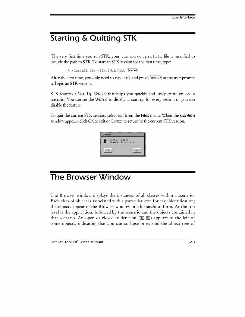
User Interface
Satellite Tool Kit® User’s Manual 2-3
Starting & Quitting STK
The very first time you run STK, your .cshrc or .profile file is modified toinclude the path to STK. To start an STK session for the first time, type:
% <Install Dir>/STKv3/bin/stk R
After the first time, you only need to type stk and press R at the user promptto begin an STK session.
STK features a Start Up Wizard that helps you quickly and easily create or load ascenario. You can set the Wizard to display at start up for every session or you candisable the feature.
To quit the current STK session, select Exit from the Files menu. When the Confirmwindow appears, click OK to exit or Cancel to return to the current STK session.
The Browser Window
The Browser window displays the instances of all classes within a scenario.Each class of object is associated with a particular icon for easy identification;the objects appear in the Browser window in a hierarchical form. At the toplevel is the application, followed by the scenario and the objects contained inthat scenario. An open or closed folder icon ( ) appears to the left ofsome objects, indicating that you can collapse or expand the object tree of
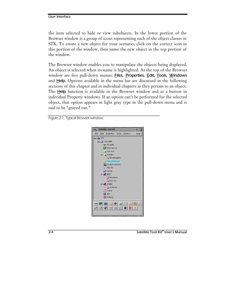
User Interface
2-4 Satellite Tool Kit® User’s Manual
the item selected to hide or view subobjects. In the lower portion of theBrowser window is a group of icons representing each of the object classes inSTK. To create a new object for your scenario, click on the correct icon inthis portion of the window, then name the new object in the top portion ofthe window.
The Browser window enables you to manipulate the objects being displayed.An object is selected when its name is highlighted. At the top of the Browserwindow are five pull-down menus: Files, Properties, Edit, Tools, Windowsand Help. Options available in the menu bar are discussed in the followingsections of this chapter and in individual chapters as they pertain to an object.The Help function is available in the Browser window and as a button inindividual Property windows. If an option can’t be performed for the selectedobject, that option appears in light gray type in the pull-down menu and issaid to be “grayed out.”
Figure 2-1. Typical Browser window.
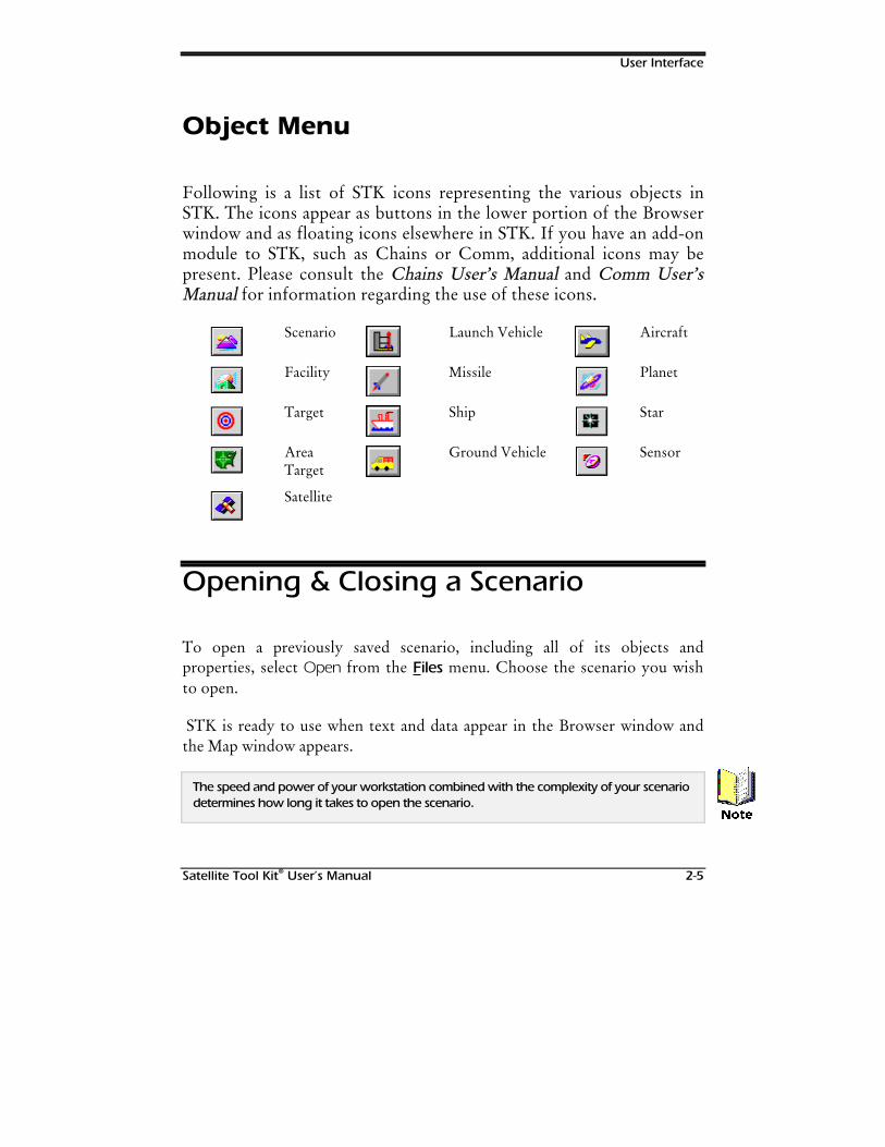
User Interface
Satellite Tool Kit® User’s Manual 2-5
Object Menu
Following is a list of STK icons representing the various objects inSTK. The icons appear as buttons in the lower portion of the Browserwindow and as floating icons elsewhere in STK. If you have an add-onmodule to STK, such as Chains or Comm, additional icons may bepresent. Please consult the CChhaaiinns s UUseserr’’s Ms Maannuuaal l and CCoomm mm UUseserr’’ssManual Manual for information regarding the use of these icons.
Scenario Launch Vehicle Aircraft
Facility Missile Planet
Target Ship Star
AreaTarget
Ground Vehicle Sensor
Satellite
Opening & Closing a Scenario
To open a previously saved scenario, including all of its objects andproperties, select Open from the Files menu. Choose the scenario you wishto open.
STK is ready to use when text and data appear in the Browser window andthe Map window appears.
The speed and power of your workstation combined with the complexity of your scenariodetermines how long it takes to open the scenario.
1RWH
User Interface
2-6 Satellite Tool Kit® User’s Manual
To close a scenario without exiting STK, highlight the scenario in theBrowser window, select Close from the Files menu. The Browser windowupdates to show only the application; the Map window(s) disappears. Youcan now open a different scenario or create a new one.
To learn more about the Map window, please refer to Chapter 3 of this manual.
Creating a New Object
To create a new object for the current scenario, highlight the scenario in theBrowser window and click on the appropriate icon (refer to page 2-5 formore information) in the lower portion of the window. When the Browserwindow displays the new object’s name, click on the highlighted text, typethe object’s new name, and press R. The object’s name can only consistof alphanumeric characters separated by an underscore ( _ ) and/or dash (-);it cannot include other punctuation marks such as commas (,), spaces orslashes (/).
You can also use the New function available from the Files menu. Just selectNew, then select the type of object you wish to create in the pull-right menuthat appears.
Inserting an Existing Object into aScenario
Any time you create or modify an object in STK, the properties of thatobject, including its state and graphical attributes, are retained in a file forthat specific object. When you create another scenario and insert the object
1RWH
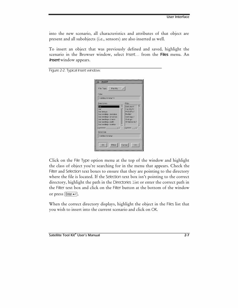
User Interface
Satellite Tool Kit® User’s Manual 2-7
into the new scenario, all characteristics and attributes of that object arepresent and all subobjects (i.e., sensors) are also inserted as well.
To insert an object that was previously defined and saved, highlight thescenario in the Browser window, select Insert… from the Files menu. AnInsert window appears.
Figure 2-2. Typical Insert window.
Click on the File Type option menu at the top of the window and highlightthe class of object you’re searching for in the menu that appears. Check theFilter and Selection text boxes to ensure that they are pointing to the directorywhere the file is located. If the Selection text box isn’t pointing to the correctdirectory, highlight the path in the Directories l ist or enter the correct path inthe Filter text box and click on the Filter button at the bottom of the windowor press R.
When the correct directory displays, highlight the object in the Files list thatyou wish to insert into the current scenario and click on OK.
User Interface
2-8 Satellite Tool Kit® User’s Manual
The Browser and Map windows are updated to include the previously definedobject.
Last Loaded Function
STK allows you to recall the last six objects opened or inserted into thecurrent STK session. The Last Loaded function, available through the Filesmenu in the Browser, features a pull-right menu that lists the last six objectsopened (i.e., scenarios) or inserted into a scenario (i.e., vehicles, facilities,targets, area targets, planets, stars, sensors).
Linking an Object into a Scenario
You can also insert a link to an existing object. To do this, highlight thescenario in the Browser window, select Insert As Link… from the Files menu.Choose the object to which you wish to insert a link and click OK in theInsert window. The object appears in the Browser window. However, objectattributes and properties can't be changed.
Saving an Object
To save a newly created object, highlight the object in the Browser window,select Save from the Files menu.
STK saves data in a hierarchical form, meaning that when you save an object,all subordinate objects are saved as well, unless you choose the Save (NoChildren) option. Thus, when you save a scenario, all objects within that
User Interface
Satellite Tool Kit® User’s Manual 2-9
scenario are saved to a file as well. In the same manner, when you save avehicle, facility or target, any sensors attached to that object are also saved. Inaddition, relationships among objects are preserved. If you insert a vehicle,any sensors attached to that vehicle are also inserted into the scenario. Thenames of any subobjects owned by the object are saved in the object file.
If you save an object using a file name that already exists, the existing file is overwrittenand previous contents are lost.
When you change an object during an STK session, noneof the changes are saved to the object’s file untilyou save either the object itself or save the parentof the object. For example, you can attach the same sensor to multiplevehicles within a given scenario and make changes to individual sensorsattached to the different vehicles within the scenario so that they appearindependently during animation. If you save the entire scenario, theproperties of the last sensor saved define and overwrite the properties of anylike-named versions of that sensor.
You can also save the object by pressing the A + S keys. For more information aboutaccelerator keys, refer to page 2-21.
Saving to a Different Directory
The STKDb directory specified in your STK run control file serves as thestarting point for any STK session. Any time you select Open, Insert… or SaveAs… from the Files menu, the default directory appears in the Selection andFilter paths. If you choose a different directory, your choice remains in effectuntil you change directories via Open, Insert… or Save As… again.
If you wish to save an object to a directory other than the current directory,highlight the object in the Browser window, select Save As… from the Filesmenu.
:DUQLQJ
+LQW
User Interface
2-10 Satellite Tool Kit® User’s Manual
Saving a Modified Object
If you modify a previously saved object and you wish to save it under thesame name, the modifications apply to all instances ofthat object in all scenarios . Consider the impact to other userswho may need the original object. To avoid potential problems with otherscenarios, use the Save As… function.
Saving the Scenario withoutChildren
If you select this option for Save or Save As…, only the selected object itselfis saved. Thus, you can save a scenario without saving any of its subobjects,or you can save a vehicle or facility without saving its attached sensors.
Removing an Object from a Scenario
You can remove an object from a scenario by highlighting the object in theBrowser window and selecting Remove from the Files menu. The object is nolonger a part of your scenario. If you saved the object previously, it’savailable for you to import into other scenarios or even this one if youchange your mind. If you didn’t save the object and it was newly created, theobject won’t be available for other scenarios. To delete an object from STK,you must be outside of STK and use commands native to your operatingsystem.
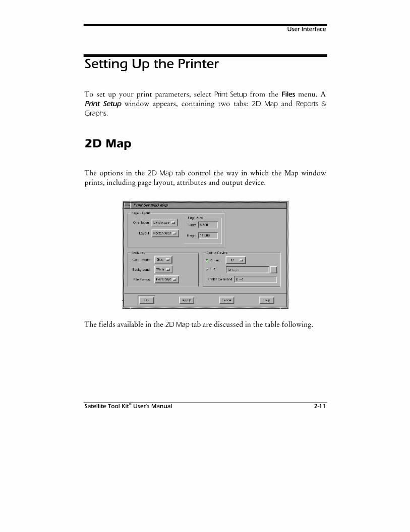
User Interface
Satellite Tool Kit® User’s Manual 2-11
Setting Up the Printer
To set up your print parameters, select Print Setup from the Files menu. APrint Setup window appears, containing two tabs: 2D Map and Reports &Graphs.
2D Map
The options in the 2D Map tab control the way in which the Map windowprints, including page layout, attributes and output device.
The fields available in the 2D Map tab are discussed in the table following.
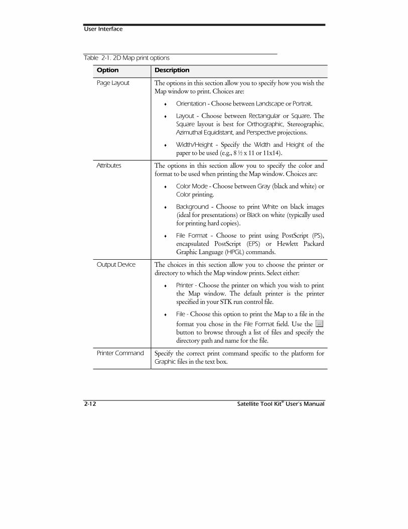
User Interface
2-12 Satellite Tool Kit® User’s Manual
Table 2-1. 2D Map print options
Option Description
Page Layout The options in this section allow you to specify how you wish theMap window to print. Choices are:
♦ Orientation - Choose between Landscape or Portrait.
♦ Layout - Choose between Rectangular or Square. TheSquare layout is best for Orthographic, Stereographic,Azimuthal Equidistant, and Perspective projections.
♦ Width/Height - Specify the Width and Height of thepaper to be used (e.g., 8 ½ x 11 or 11x14).
Attributes The options in this section allow you to specify the color andformat to be used when printing the Map window. Choices are:
♦ Color Mode - Choose between Gray (black and white) orColor printing.
♦ Background - Choose to print White on black images(ideal for presentations) or Black on white (typically usedfor printing hard copies).
♦ File Format - Choose to print using PostScript (PS),encapsulated PostScript (EPS) or Hewlett PackardGraphic Language (HPGL) commands.
Output Device The choices in this section allow you to choose the printer ordirectory to which the Map window prints. Select either:
♦ Printer - Choose the printer on which you wish to printthe Map window. The default printer is the printerspecified in your STK run control file.
♦ File - Choose this option to print the Map to a file in theformat you chose in the File Format field. Use the button to browse through a list of files and specify thedirectory path and name for the file.
Printer Command Specify the correct print command specific to the platform forGraphic files in the text box.
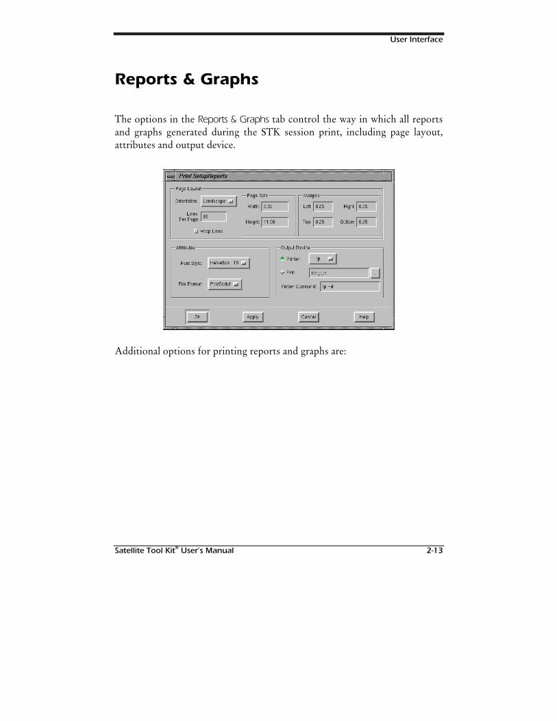
User Interface
Satellite Tool Kit® User’s Manual 2-13
Reports & Graphs
The options in the Reports & Graphs tab control the way in which all reportsand graphs generated during the STK session print, including page layout,attributes and output device.
Additional options for printing reports and graphs are:
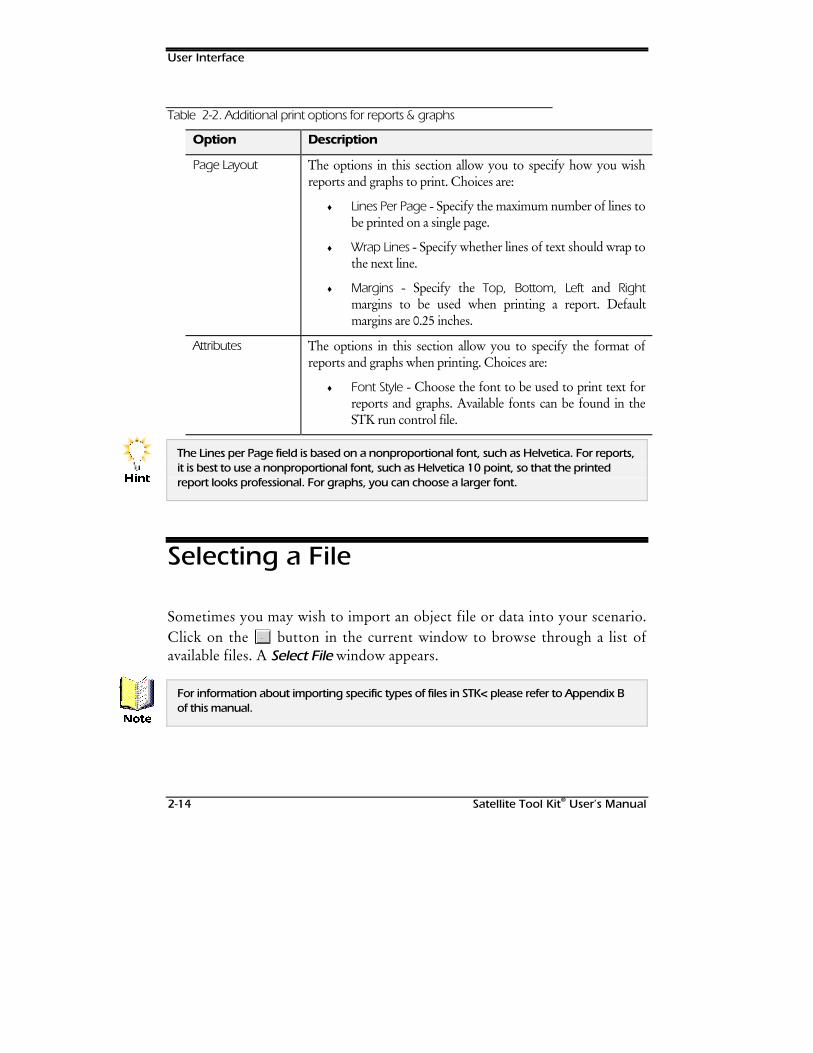
User Interface
2-14 Satellite Tool Kit® User’s Manual
Table 2-2. Additional print options for reports & graphs
Option Description
Page Layout The options in this section allow you to specify how you wishreports and graphs to print. Choices are:
♦ Lines Per Page - Specify the maximum number of lines tobe printed on a single page.
♦ Wrap Lines - Specify whether lines of text should wrap tothe next line.
♦ Margins - Specify the Top, Bottom, Left and Rightmargins to be used when printing a report. Defaultmargins are 0.25 inches.
Attributes The options in this section allow you to specify the format ofreports and graphs when printing. Choices are:
♦ Font Style - Choose the font to be used to print text forreports and graphs. Available fonts can be found in theSTK run control file.
The Lines per Page field is based on a nonproportional font, such as Helvetica. For reports,it is best to use a nonproportional font, such as Helvetica 10 point, so that the printedreport looks professional. For graphs, you can choose a larger font.
Selecting a File
Sometimes you may wish to import an object file or data into your scenario.Click on the button in the current window to browse through a list ofavailable files. A Select File window appears.
For information about importing specific types of files in STK< please refer to Appendix Bof this manual.
+LQW
1RWH
User Interface
Satellite Tool Kit® User’s Manual 2-15
Editing in STK
STK now features traditional Copy, Cut and Paste options so that you caneasily use data in more than one place. These features are available throughthe Edit menu in the Browser for vehicles, facilities, targets, area targets,planets, stars and sensors.
Opening an STK Module or ExternalApplication
STK includes a large family of products that are integrated with the STKapplication. Some functions are seamlessly integrated into STK, such asComm, IPC and Chains. Other applications, developed by companiesworking in partnership with Analytical Graphics, are integrated into STKthrough the External Apps option in the Files menu. If you have licenses forapplications such as Missile Flight Tool (MFT), GREAS or otherapplications, use the External Apps option to display a pull-right menu listingavailable applications.
Defining the Properties of an Object
You can define an object’s basic and graphics properties as well as constraintsfor the object by selecting an option in the Properties menu. Properties foreach object are discussed in subsequent chapters of this manual. Please referto the specific object for instructions on setting object properties.
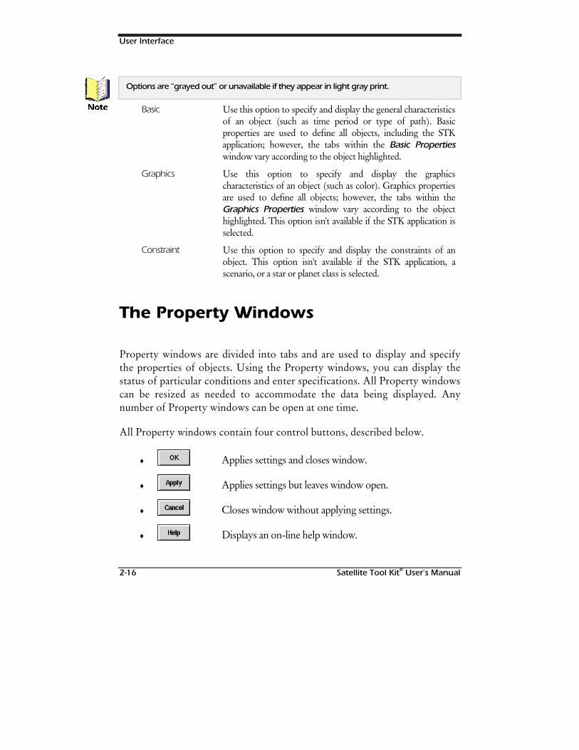
User Interface
2-16 Satellite Tool Kit® User’s Manual
Options are “grayed out” or unavailable if they appear in light gray print.
Basic Use this option to specify and display the general characteristicsof an object (such as time period or type of path). Basicproperties are used to define all objects, including the STKapplication; however, the tabs within the Basic Propertieswindow vary according to the object highlighted.
Graphics Use this option to specify and display the graphicscharacteristics of an object (such as color). Graphics propertiesare used to define all objects; however, the tabs within theGraphics Properties window vary according to the objecthighlighted. This option isn't available if the STK application isselected.
Constraint Use this option to specify and display the constraints of anobject. This option isn't available if the STK application, ascenario, or a star or planet class is selected.
The Property Windows
Property windows are divided into tabs and are used to display and specifythe properties of objects. Using the Property windows, you can display thestatus of particular conditions and enter specifications. All Property windowscan be resized as needed to accommodate the data being displayed. Anynumber of Property windows can be open at one time.
All Property windows contain four control buttons, described below.
♦ Applies settings and closes window.
♦ Applies settings but leaves window open.
♦ Closes window without applying settings.
♦ Displays an on-line help window.
1RWH
User Interface
Satellite Tool Kit® User’s Manual 2-17
Describing an Object in STK
When you create a scenario, or any other object, you may want to recordancillary information for future reference. The Description tab of theBasic Properties window allows you to create a short and/or long descriptionof the object to be saved with the object.
The Short Description field is limited to one line of text and the LongDescription field is limited to 511 characters, including spaces andpunctuation. The Description tab exists as a basic property of the scenario andall objects that can be contained in a scenario.
Using Multiple Windows
To better control and organize the various tasks you perform in STK, theWindows menu lists each of the windows, whether Map or property, that areopen during an STK session. You can select the window of interest to bring itto the front. This is especially useful if the scenario includes multiple Mapwindows and you have a number of object property windows open. Inaddition, you can toggle between allowing only one instance of the samewindow to be open at any one given time or allowing multiple copies of thesame window to be open simultaneously.
Using STK Tools
You can use specialized STK tools to perform analyses tasks and assist you indefining and displaying accesses, lighting conditions, vehicle swaths andWalker constellations. Tools are also available for creating standard and
User Interface
2-18 Satellite Tool Kit® User’s Manual
customized reports, viewing report data in graph form to better analyze data,easily importing known satellites with user-friendly search parameters,removing accesses and restoring the Map window. STK tools are discussed indetail in Chapters 13 through 16Chapters 13 through 16 of this manual.
Using Help
STK features detailed Help that can assist you in completing tasks bydisplaying on-line instructions. You can display general Help in the Browserwindow or task-specific Help in individual Property windows. An overviewof the Help system is provided in Chapter 17Chapter 17 of this manual.
Making Choices in STK
Another fundamental concept in STK involves toggle buttons, option menus,lists and radio buttons that provide you with a choice of options.
Selecting Multiple Objects
You can select multiple objects in the Browser window by pressing andholding the S to select tangent objects or C to select miscellaneousobjects. Once you’ve selected multiple objects in the Browser, you can usethe Report and Graph tools to collectively display information about theobjects.
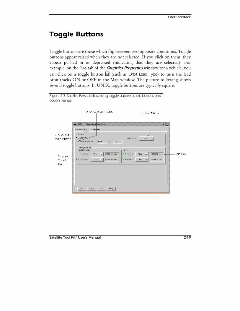
User Interface
Satellite Tool Kit® User’s Manual 2-19
Toggle Buttons
Toggle buttons are those which flip between two opposite conditions. Togglebuttons appear raised when they are not selected. If you click on them, theyappear pushed in or depressed (indicating that they are selected). Forexample, on the Pass tab of the Graphics Properties window for a vehicle, youcan click on a toggle button (such as Orbit Lead Type) to turn the leadorbit tracks ON or OFF in the Map window. The picture following showsseveral toggle buttons. In UNIX, toggle buttons are typically square.
Figure 2-3. Satellite Pass tab illustrating toggle buttons, radio buttons andoption menus.
6HOHFWHG 5DGLR %XWWRQ2SWLRQ 0HQX
8QVHOHFWHG
5DGLR %XWWRQ
6HOHFWHG
7RJJOH
%XWWRQ
7H[W %R[
User Interface
2-20 Satellite Tool Kit® User’s Manual
Option Menus
Option menus, shown in the Graphics Properties window, allow you to selectone and only one item from a list that appears when you click and hold theassociated option menu button. To select an item other than the onecurrently displayed on the face of the option menu, click on the option menu
and use the mouse to highlight the item of interest in the list thatappears, then release the mouse. Option menus can be identified by smallrectangles on the right side of the button, or a down-pointing arrow to theright of the field’s name.
Radio Buttons
Radio buttons occur in a group. You can select one and only one item inthe group of radio buttons (similar to the way the radio buttons work in yourcar). For example, the Pass tab of the Graphics Properties window featuresradio buttons that allow you to choose between displaying all pass data in theMap window or displaying a specified range of pass data. In Motif, radiobuttons are typically diamond shaped.
Lists
Lists, such as the Items list shown in the Map Details tab, allow you to selectmultiple items in a scrollable area. The Map Details tab allows you to choosewhich map features you wish to see displayed in the Map window. To selectan item, click on the item within the scrollable field so that it is highlighted.To remove an item from the list, click on the highlighted item again.
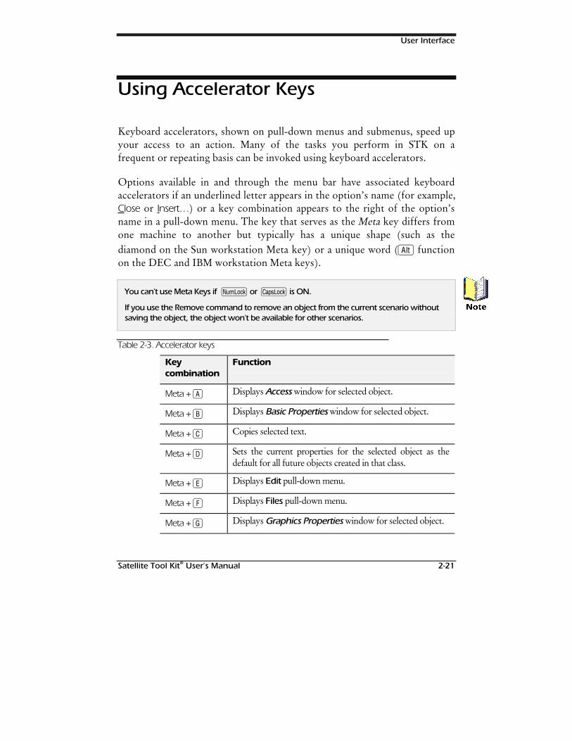
User Interface
Satellite Tool Kit® User’s Manual 2-21
Using Accelerator Keys
Keyboard accelerators, shown on pull-down menus and submenus, speed upyour access to an action. Many of the tasks you perform in STK on afrequent or repeating basis can be invoked using keyboard accelerators.
Options available in and through the menu bar have associated keyboardaccelerators if an underlined letter appears in the option’s name (for example,Close or Insert…) or a key combination appears to the right of the option’sname in a pull-down menu. The key that serves as the Meta key differs fromone machine to another but typically has a unique shape (such as thediamond on the Sun workstation Meta key) or a unique word (A functionon the DEC and IBM workstation Meta keys).
You can’t use Meta Keys if n or c is ON.
If you use the Remove command to remove an object from the current scenario withoutsaving the object, the object won’t be available for other scenarios.
Table 2-3. Accelerator keys
Keycombination
Function
Meta + A Displays Access window for selected object.
Meta + B Displays Basic Properties window for selected object.
Meta + C Copies selected text.
Meta + D Sets the current properties for the selected object as thedefault for all future objects created in that class.
Meta + E Displays Edit pull-down menu.
Meta + F Displays Files pull-down menu.
Meta + G Displays Graphics Properties window for selected object.
1RWH
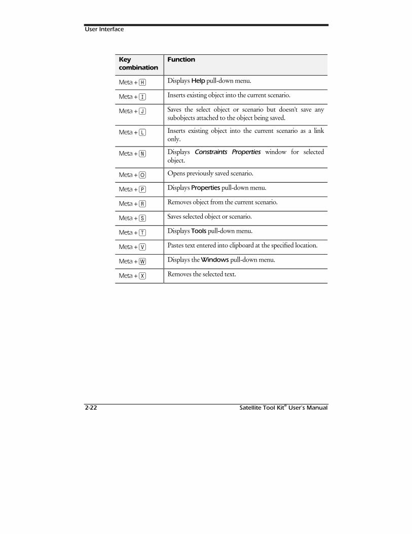
User Interface
2-22 Satellite Tool Kit® User’s Manual
Keycombination
Function
Meta + H Displays Help pull-down menu.
Meta + I Inserts existing object into the current scenario.
Meta + J Saves the select object or scenario but doesn't save anysubobjects attached to the object being saved.
Meta + l Inserts existing object into the current scenario as a linkonly.
Meta + N Displays Constraints Properties window for selectedobject.
Meta + O Opens previously saved scenario.
Meta + P Displays Properties pull-down menu.
Meta + R Removes object from the current scenario.
Meta + S Saves selected object or scenario.
Meta + T Displays Tools pull-down menu.
Meta + V Pastes text entered into clipboard at the specified location.
Meta + W Displays the Windows pull-down menu.
Meta + X Removes the selected text.
Satellite Tool Kit® User's Manual 3-1
3THE MAP
WINDOW
Overview
The Map window graphically displays information about your scenario. Usethe tool bar, located at the top of the Map window, to control animation andzooming. Use the status bar, located along the bottom of the window, tocheck the cursor’s latitude and longitude position, the name of the selectedobject, and the current scenario time. You can specify a number of Mapwindow display options directly from an STK session, including map colors,geographic features, display format, latitude/longitude line spacing, etc. Inaddition, you can open multiple Map windows for a single scenario withdifferent display options to further your analysis efforts.
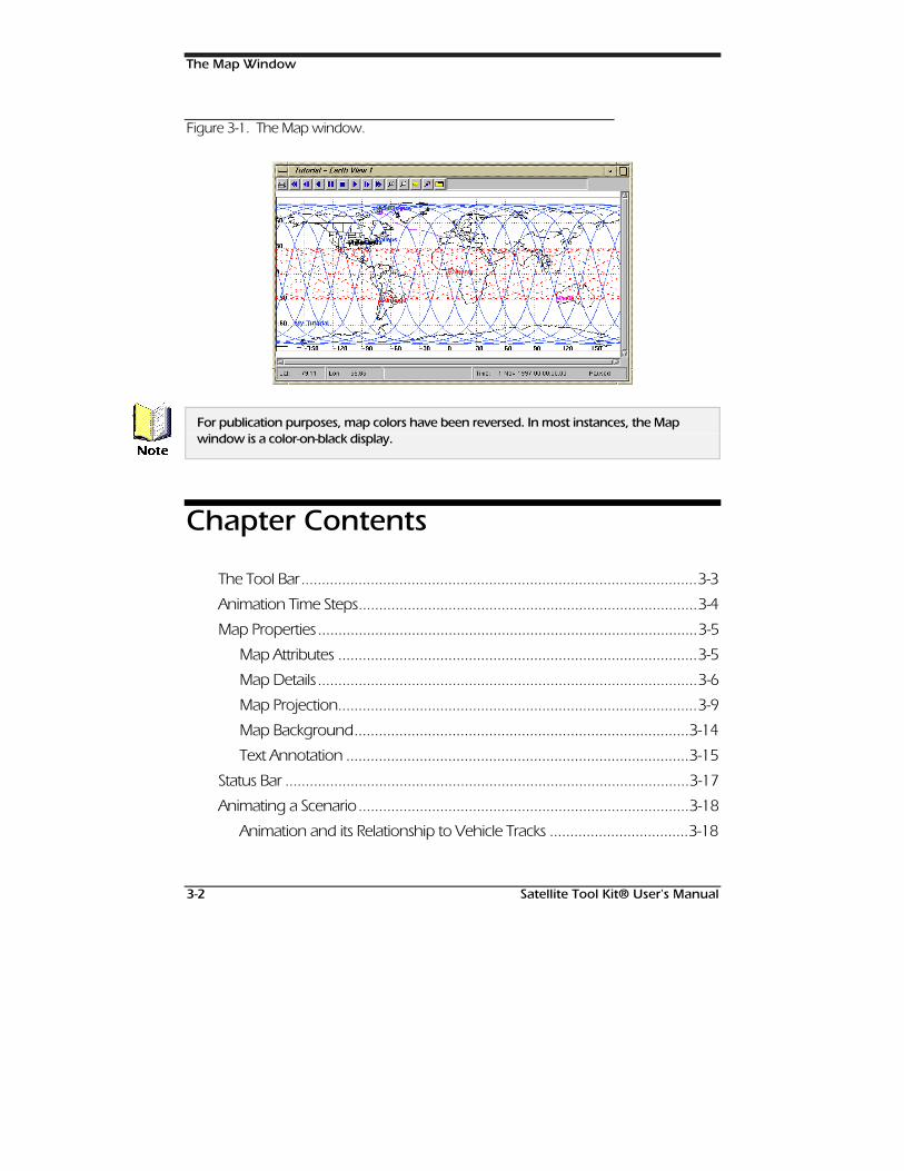
The Map Window
3-2 Satellite Tool Kit® User's Manual
Figure 3-1. The Map window.
For publication purposes, map colors have been reversed. In most instances, the Mapwindow is a color-on-black display.
Chapter Contents
The Tool Bar.................................................................................................3-3
Animation Time Steps...................................................................................3-4
Map Properties.............................................................................................3-5
Map Attributes ........................................................................................3-5
Map Details.............................................................................................3-6
Map Projection........................................................................................3-9
Map Background..................................................................................3-14
Text Annotation ....................................................................................3-15
Status Bar ...................................................................................................3-17
Animating a Scenario.................................................................................3-18
Animation and its Relationship to Vehicle Tracks ..................................3-18
1RWH
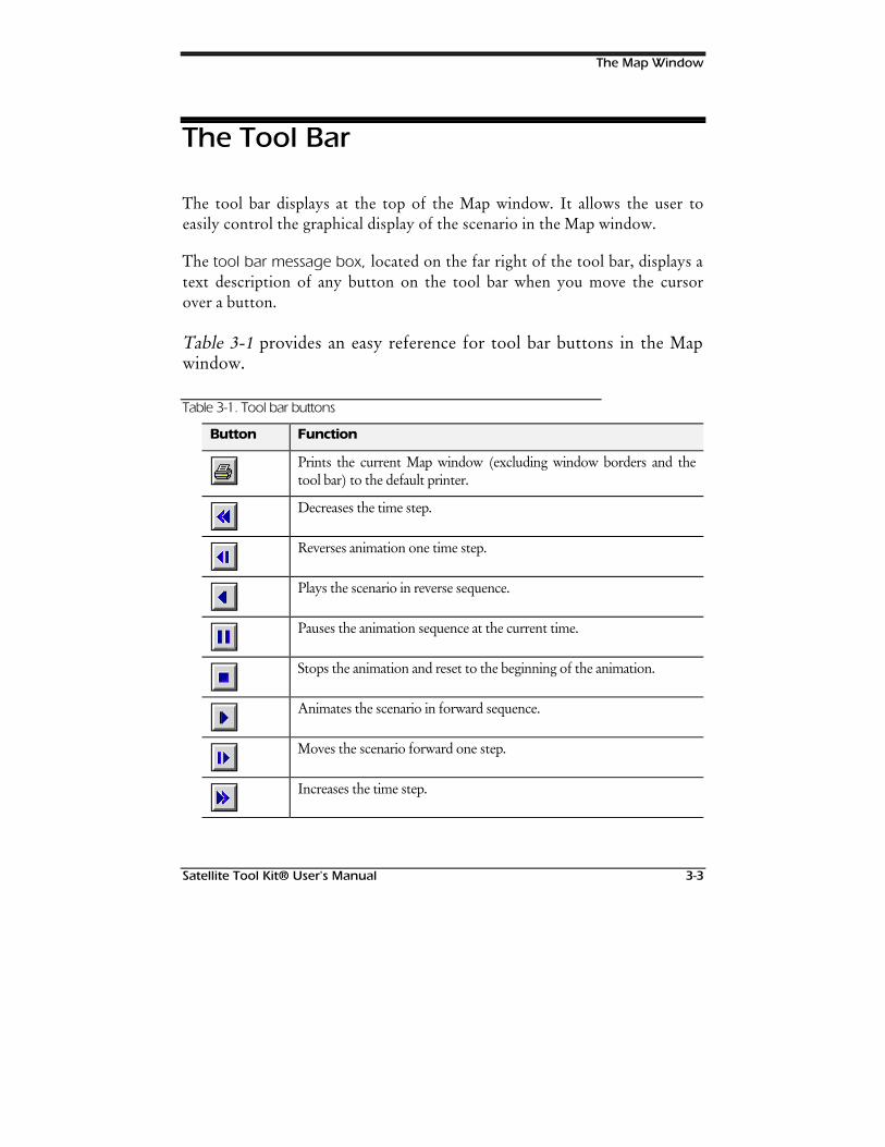
The Map Window
Satellite Tool Kit® User's Manual 3-3
The Tool Bar
The tool bar displays at the top of the Map window. It allows the user toeasily control the graphical display of the scenario in the Map window.
The tool bar message box, located on the far right of the tool bar, displays atext description of any button on the tool bar when you move the cursorover a button.
Table 3-1 provides an easy reference for tool bar buttons in the Mapwindow.
Table 3-1. Tool bar buttons
Button Function
Prints the current Map window (excluding window borders and thetool bar) to the default printer.
Decreases the time step.
Reverses animation one time step.
Plays the scenario in reverse sequence.
Pauses the animation sequence at the current time.
Stops the animation and reset to the beginning of the animation.
Animates the scenario in forward sequence.
Moves the scenario forward one step.
Increases the time step.
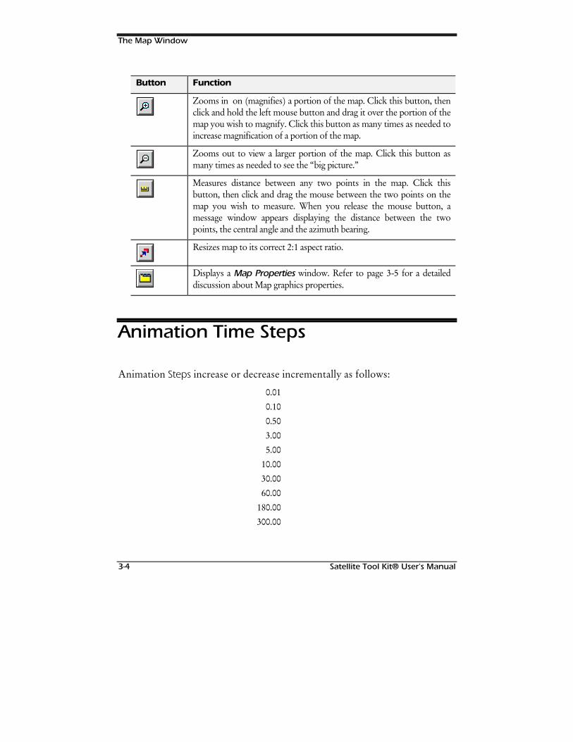
The Map Window
3-4 Satellite Tool Kit® User's Manual
Button Function
Zooms in on (magnifies) a portion of the map. Click this button, thenclick and hold the left mouse button and drag it over the portion of themap you wish to magnify. Click this button as many times as needed toincrease magnification of a portion of the map.
Zooms out to view a larger portion of the map. Click this button asmany times as needed to see the “big picture.”
Measures distance between any two points in the map. Click thisbutton, then click and drag the mouse between the two points on themap you wish to measure. When you release the mouse button, amessage window appears displaying the distance between the twopoints, the central angle and the azimuth bearing.
Resizes map to its correct 2:1 aspect ratio.
Displays a Map Properties window. Refer to page 3-5 for a detaileddiscussion about Map graphics properties.
Animation Time Steps
Animation Steps increase or decrease incrementally as follows:
0.010.100.503.005.00
10.0030.0060.00
180.00300.00
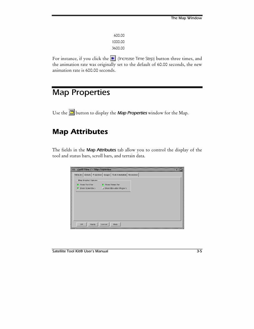
The Map Window
Satellite Tool Kit® User's Manual 3-5
600.001000.003600.00
For instance, if you click the (Increase Time Step) button three times, andthe animation rate was originally set to the default of 60.00 seconds, the newanimation rate is 600.00 seconds.
Map Properties
Use the button to display the Map Properties window for the Map.
Map Attributes
The fields in the Map Attributes tab allow you to control the display of thetool and status bars, scroll bars, and terrain data.
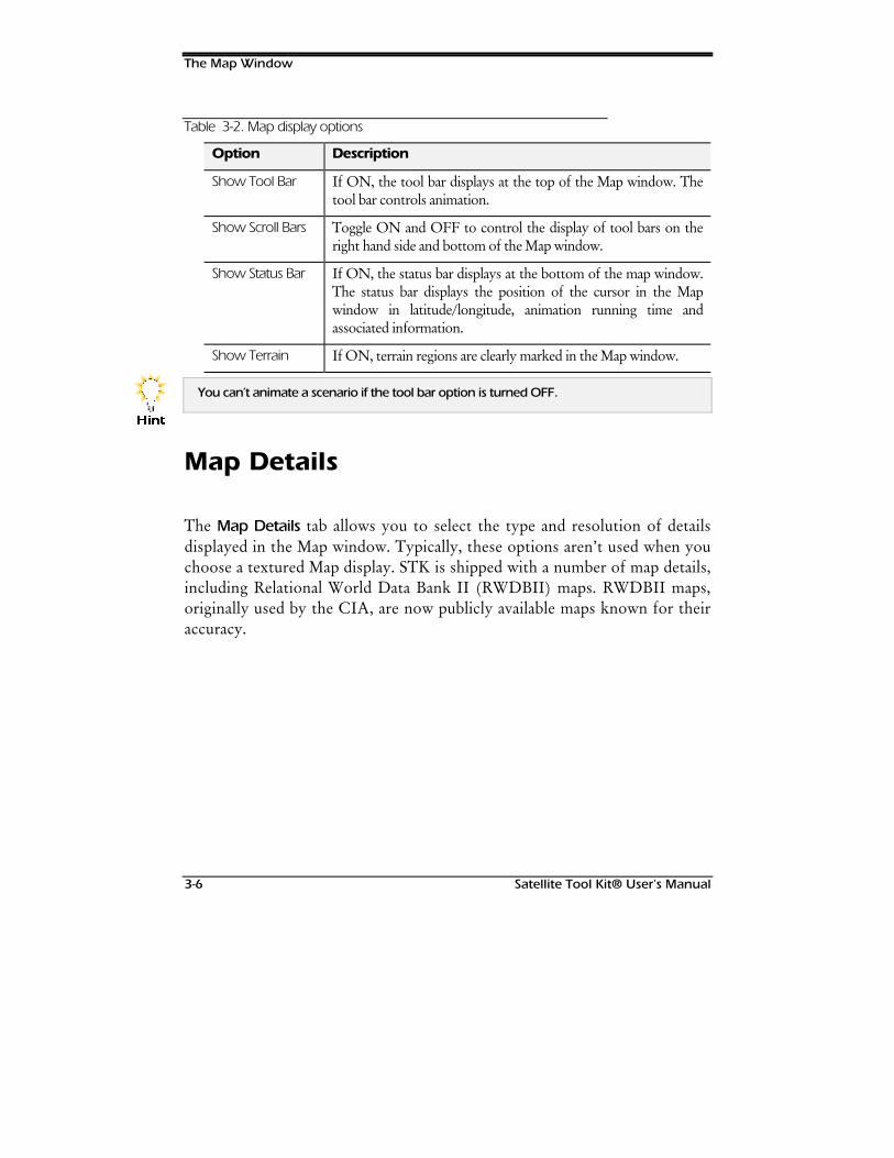
The Map Window
3-6 Satellite Tool Kit® User's Manual
Table 3-2. Map display options
Option Description
Show Tool Bar If ON, the tool bar displays at the top of the Map window. Thetool bar controls animation.
Show Scroll Bars Toggle ON and OFF to control the display of tool bars on theright hand side and bottom of the Map window.
Show Status Bar If ON, the status bar displays at the bottom of the map window.The status bar displays the position of the cursor in the Mapwindow in latitude/longitude, animation running time andassociated information.
Show Terrain If ON, terrain regions are clearly marked in the Map window.
You can’t animate a scenario if the tool bar option is turned OFF.
Map Details
The Map Details tab allows you to select the type and resolution of detailsdisplayed in the Map window. Typically, these options aren’t used when youchoose a textured Map display. STK is shipped with a number of map details,including Relational World Data Bank II (RWDBII) maps. RWDBII maps,originally used by the CIA, are now publicly available maps known for theiraccuracy.
+LQW
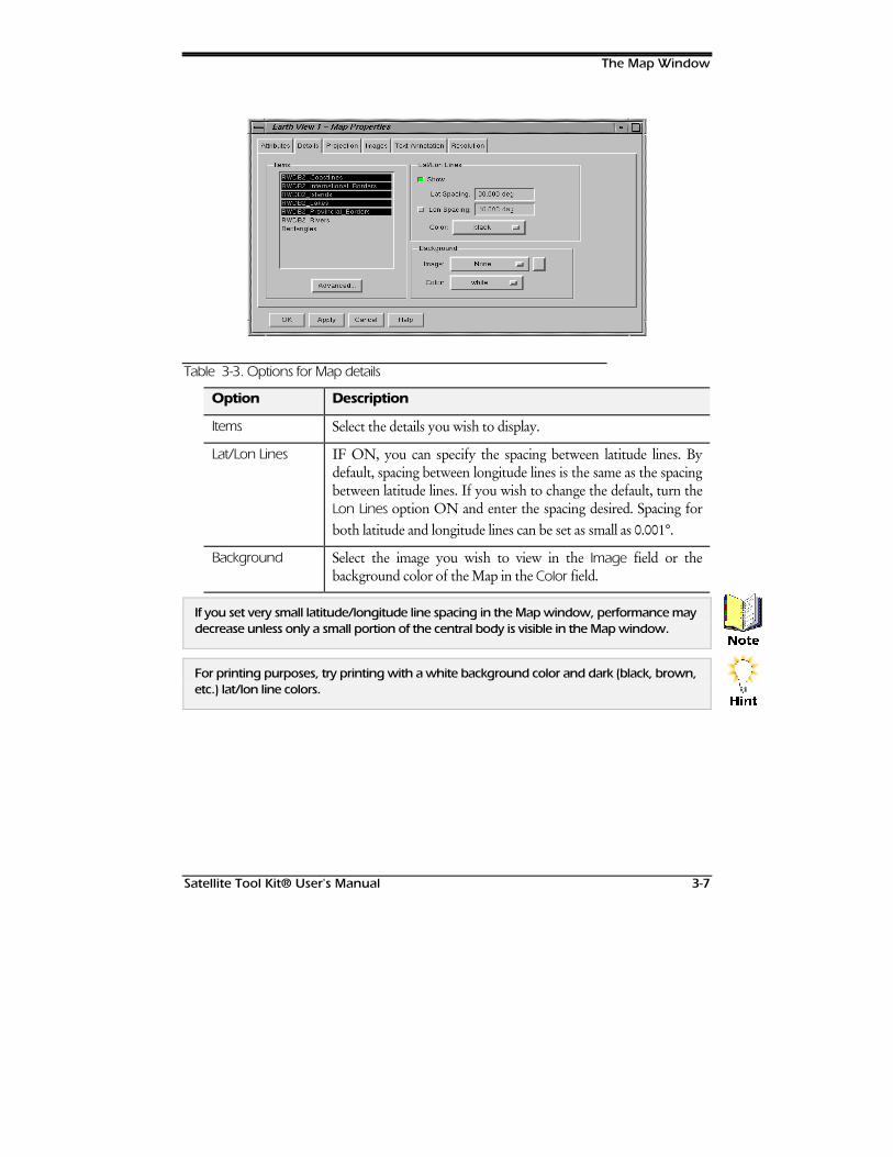
The Map Window
Satellite Tool Kit® User's Manual 3-7
Table 3-3. Options for Map details
Option Description
Items Select the details you wish to display.
Lat/Lon Lines IF ON, you can specify the spacing between latitude lines. Bydefault, spacing between longitude lines is the same as the spacingbetween latitude lines. If you wish to change the default, turn theLon Lines option ON and enter the spacing desired. Spacing forboth latitude and longitude lines can be set as small as 0.001°.
Background Select the image you wish to view in the Image field or thebackground color of the Map in the Color field.
If you set very small latitude/longitude line spacing in the Map window, performance maydecrease unless only a small portion of the central body is visible in the Map window.
For printing purposes, try printing with a white background color and dark (black, brown,etc.) lat/lon line colors.
1RWH
+LQW

The Map Window
3-8 Satellite Tool Kit® User's Manual
Advanced Details
Use the Advanced… button to fine tune the map display by controlling thedisplay and color of specific map details.
Select the category of interest, then specify whether the level of detailselected should be displayed in the Map window. If the Display option is setto Yes, specify the Color in which the details should be displayed. Details in aspecific category, such as international borders, can be dealt with as a group,or you can specify the display and color of particular features within thecategory, such as demilitarized zone lines and specified claimed lines. Tomake the display and color of all map details uniform, use the Select All button.
Hi-Resolution Maps (Module)
This module contains comprehensive, very-high-resolution mapping data forthe entire globe. The data includes coastlines, rivers, lakes and political boundaries atapproximately 1 arc second or 30 meter resolution. This is ideal for visualizingground tracks and coverage areas over small geographic regions. Special data accessalgorithms have been incorporated to support rapid visualization of localized mapdata. The data was extracted from the 1995 CIA RWDB2 database and requiresalmost 200 MB of storage. It is formatted for optimal performance with STK.
PRO/PRO/Hi-ResHi-ResMapsMaps
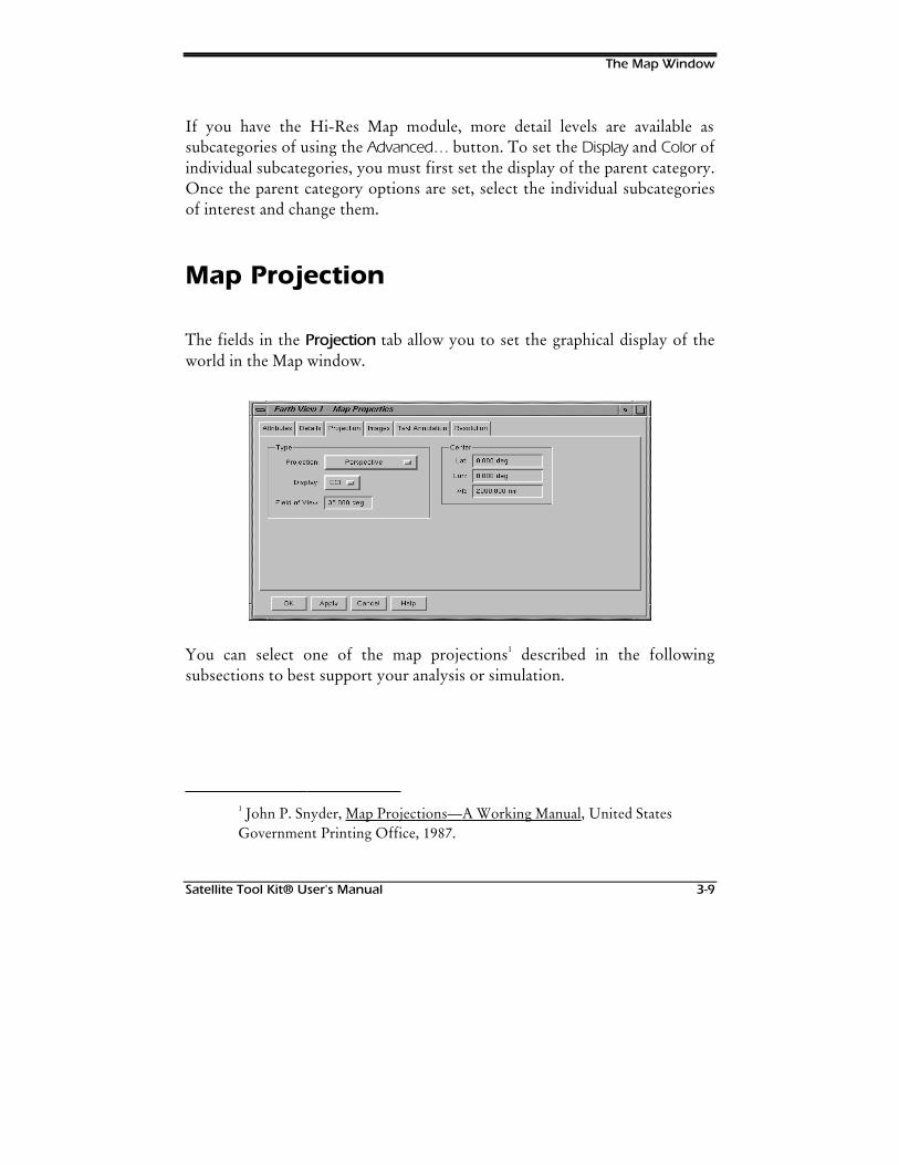
The Map Window
Satellite Tool Kit® User's Manual 3-9
If you have the Hi-Res Map module, more detail levels are available assubcategories of using the Advanced… button. To set the Display and Color ofindividual subcategories, you must first set the display of the parent category.Once the parent category options are set, select the individual subcategoriesof interest and change them.
Map Projection
The fields in the Projection tab allow you to set the graphical display of theworld in the Map window.
You can select one of the map projections1 described in the followingsubsections to best support your analysis or simulation.
1 John P. Snyder, Map Projections—A Working Manual, United StatesGovernment Printing Office, 1987.
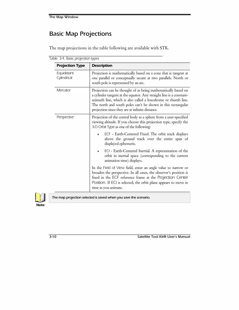
The Map Window
3-10 Satellite Tool Kit® User's Manual
Basic Map Projections
The map projections in the table following are available with STK.
Table 3-4. Basic projection types
Projection Type Description
EquidistantCylindrical
Projection is mathematically based on a cone that is tangent atone parallel or conceptually secant at two parallels. North orsouth pole is represented by an arc.
Mercator Projection can be thought of as being mathematically based ona cylinder tangent at the equator. Any straight line is a constant-azimuth line, which is also called a loxodrome or rhumb line.The north and south poles can’t be shown in this rectangularprojection since they are at infinite distance.
Perspective Projection of the central body as a sphere from a user-specifiedviewing altitude. If you choose this projection type, specify the3-D Orbit Type as one of the following:
♦ ECF - Earth-Centered Fixed. The orbit track displaysabove the ground track over the entire span ofdisplayed ephemeris.
♦ ECI - Earth-Centered Inertial. A representation of theorbit in inertial space (corresponding to the currentanimation time) displays.
In the Field of View field, enter an angle value to narrow orbroaden the perspective. In all cases, the observer’s position isfixed in the ECF reference frame at the Projection CenterPosition. If ECI is selected, the orbit plane appears to move intime as you animate.
The map projection selected is saved when you save the scenario.
1RWH
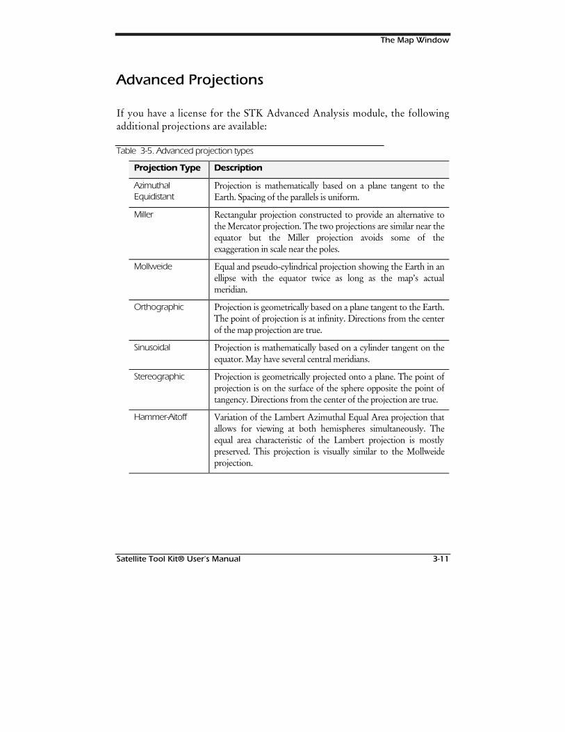
The Map Window
Satellite Tool Kit® User's Manual 3-11
Advanced Projections
If you have a license for the STK Advanced Analysis module, the followingadditional projections are available:
Table 3-5. Advanced projection types
Projection Type Description
AzimuthalEquidistant
Projection is mathematically based on a plane tangent to theEarth. Spacing of the parallels is uniform.
Miller Rectangular projection constructed to provide an alternative tothe Mercator projection. The two projections are similar near theequator but the Miller projection avoids some of theexaggeration in scale near the poles.
Mollweide Equal and pseudo-cylindrical projection showing the Earth in anellipse with the equator twice as long as the map’s actualmeridian.
Orthographic Projection is geometrically based on a plane tangent to the Earth.The point of projection is at infinity. Directions from the centerof the map projection are true.
Sinusoidal Projection is mathematically based on a cylinder tangent on theequator. May have several central meridians.
Stereographic Projection is geometrically projected onto a plane. The point ofprojection is on the surface of the sphere opposite the point oftangency. Directions from the center of the projection are true.
Hammer-Aitoff Variation of the Lambert Azimuthal Equal Area projection thatallows for viewing at both hemispheres simultaneously. Theequal area characteristic of the Lambert projection is mostlypreserved. This projection is visually similar to the Mollweideprojection.
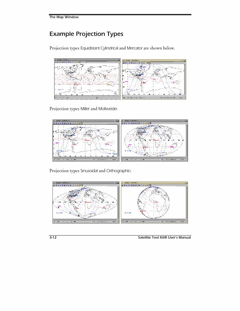
The Map Window
3-12 Satellite Tool Kit® User's Manual
Example Projection Types
Projection types Equidistant Cylindrical and Mercator are shown below.
Projection types Miller and Mollweide:
Projection types Sinusoidal and Orthographic:
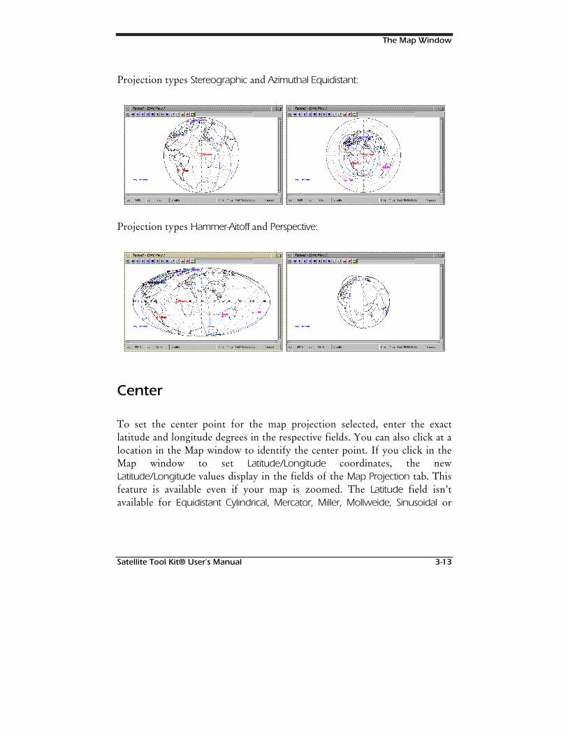
The Map Window
Satellite Tool Kit® User's Manual 3-13
Projection types Stereographic and Azimuthal Equidistant:
Projection types Hammer-Aitoff and Perspective:
Center
To set the center point for the map projection selected, enter the exactlatitude and longitude degrees in the respective fields. You can also click at alocation in the Map window to identify the center point. If you click in theMap window to set Latitude/Longitude coordinates, the newLatitude/Longitude values display in the fields of the Map Projection tab. Thisfeature is available even if your map is zoomed. The Latitude field isn’tavailable for Equidistant Cylindrical, Mercator, Miller, Mollweide, Sinusoidal or
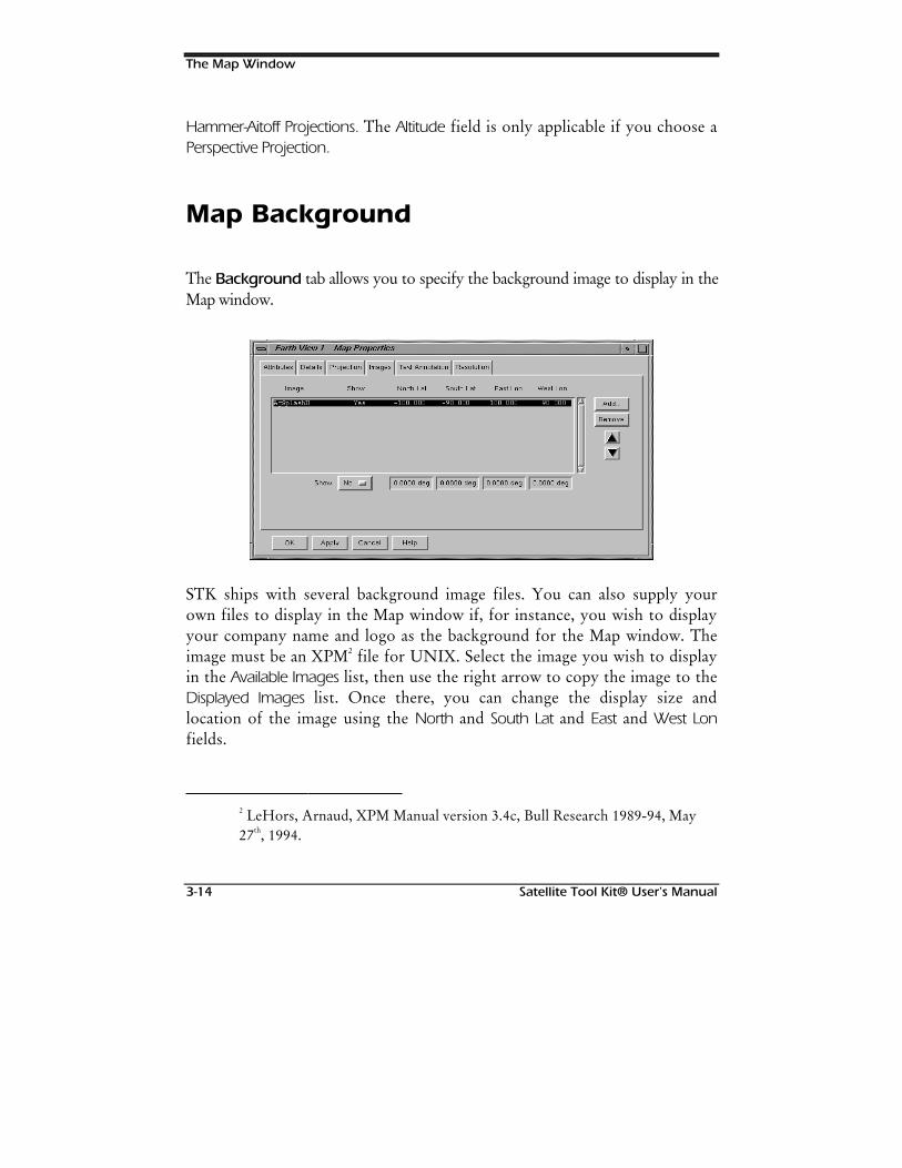
The Map Window
3-14 Satellite Tool Kit® User's Manual
Hammer-Aitoff Projections. The Altitude field is only applicable if you choose aPerspective Projection.
Map Background
The Background tab allows you to specify the background image to display in theMap window.
STK ships with several background image files. You can also supply yourown files to display in the Map window if, for instance, you wish to displayyour company name and logo as the background for the Map window. Theimage must be an XPM2 file for UNIX. Select the image you wish to displayin the Available Images list, then use the right arrow to copy the image to theDisplayed Images list. Once there, you can change the display size andlocation of the image using the North and South Lat and East and West Lonfields.
2 LeHors, Arnaud, XPM Manual version 3.4c, Bull Research 1989-94, May27th, 1994.
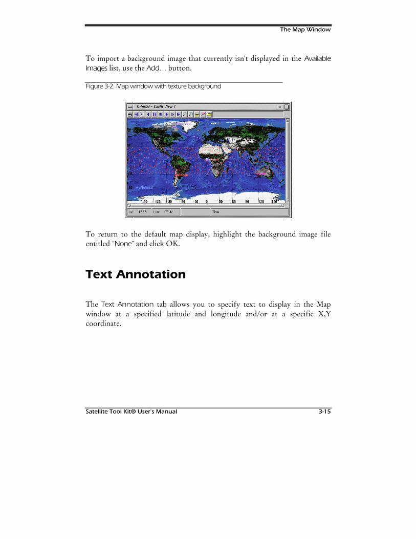
The Map Window
Satellite Tool Kit® User's Manual 3-15
To import a background image that currently isn't displayed in the AvailableImages list, use the Add… button.
Figure 3-2. Map window with texture background
To return to the default map display, highlight the background image fileentitled “None” and click OK.
Text Annotation
The Text Annotation tab allows you to specify text to display in the Mapwindow at a specified latitude and longitude and/or at a specific X,Ycoordinate.
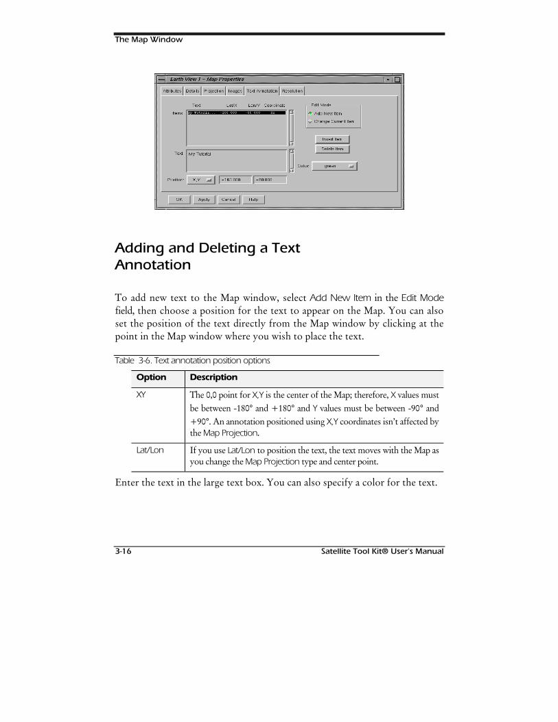
The Map Window
3-16 Satellite Tool Kit® User's Manual
Adding and Deleting a TextAnnotation
To add new text to the Map window, select Add New Item in the Edit Modefield, then choose a position for the text to appear on the Map. You can alsoset the position of the text directly from the Map window by clicking at thepoint in the Map window where you wish to place the text.
Table 3-6. Text annotation position options
Option Description
XY The 0,0 point for X,Y is the center of the Map; therefore, X values mustbe between -180° and +180° and Y values must be between -90° and+90°. An annotation positioned using X,Y coordinates isn’t affected bythe Map Projection.
Lat/Lon If you use Lat/Lon to position the text, the text moves with the Map asyou change the Map Projection type and center point.
Enter the text in the large text box. You can also specify a color for the text.
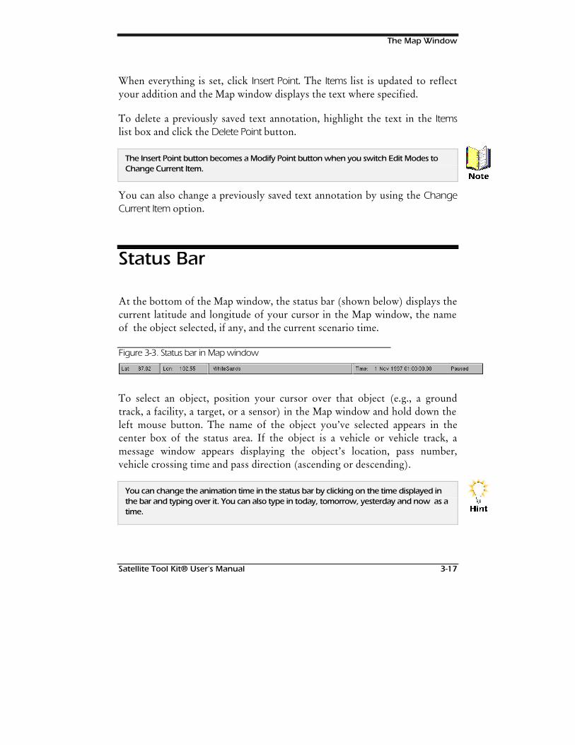
The Map Window
Satellite Tool Kit® User's Manual 3-17
When everything is set, click Insert Point. The Items list is updated to reflectyour addition and the Map window displays the text where specified.
To delete a previously saved text annotation, highlight the text in the Itemslist box and click the Delete Point button.
The Insert Point button becomes a Modify Point button when you switch Edit Modes toChange Current Item.
You can also change a previously saved text annotation by using the ChangeCurrent Item option.
Status Bar
At the bottom of the Map window, the status bar (shown below) displays thecurrent latitude and longitude of your cursor in the Map window, the nameof the object selected, if any, and the current scenario time.
Figure 3-3. Status bar in Map window
To select an object, position your cursor over that object (e.g., a groundtrack, a facility, a target, or a sensor) in the Map window and hold down theleft mouse button. The name of the object you’ve selected appears in thecenter box of the status area. If the object is a vehicle or vehicle track, amessage window appears displaying the object’s location, pass number,vehicle crossing time and pass direction (ascending or descending).
You can change the animation time in the status bar by clicking on the time displayed inthe bar and typing over it. You can also type in today, tomorrow, yesterday and now as atime.
1RWH
+LQW
The Map Window
3-18 Satellite Tool Kit® User's Manual
Animating a Scenario
As you define and analyze a scenario using STK, you can animate thescenario to more fully understand time-based relationships and interactions.Because satellite systems are so dynamic, it is important to analyze thescenario in motion.
For the animation of a scenario to be meaningful, the objects in the scenariowith time dependencies should be properly defined. For example, vehiclesmust have ephemeris within the animation period to be affected by thescenario animation. Animating the scenario displays vehicles moving alongtheir ground tracks, the intersections of sensors with the central body andthe subobject locations for planet and stars.
If you're animating a scenario in the Map window and need to perform other tasks in STK,you may want to first Pause the animation and then begin other tasks. If you animatewhile multitasking, all other processes/ applications are slowed down.
Animation and its Relationship toVehicle Tracks
In preparing to animate a scenario in STK, it is important to understand therelationship between the date/time established for orbital elements and thedate/time established for the animation. You must propagate a path and generateephemeris for a vehicle that overlaps all or a portion of the date and time range setfor the scenario animation. If the date and time of animation fall outside the rangeof available ephemeris, the vehicle doesn’t move during animation. You must eitherpropagate ephemeris that use the date and time set for the scenario animation oryou need to change the date and time for your scenario animation so that it fallswithin the span of the available ephemeris.
1RWH
Satellite Tool Kit® User’s Manual 4-1
4STK APPLICATION
Overview
The STK application contains your scenario and all of the objects in thescenario. When you set properties at the application level, they remain ineffect for all scenarios, whether they are previously saved scenarios openedduring an STK session or newly created scenarios.
Chapter Contents
Basic Properties: STK Save Prefs ....................................................................4-2
Basic Properties: IPC Preferences ..................................................................4-3
Basic Properties: Online Operations.............................................................4-5
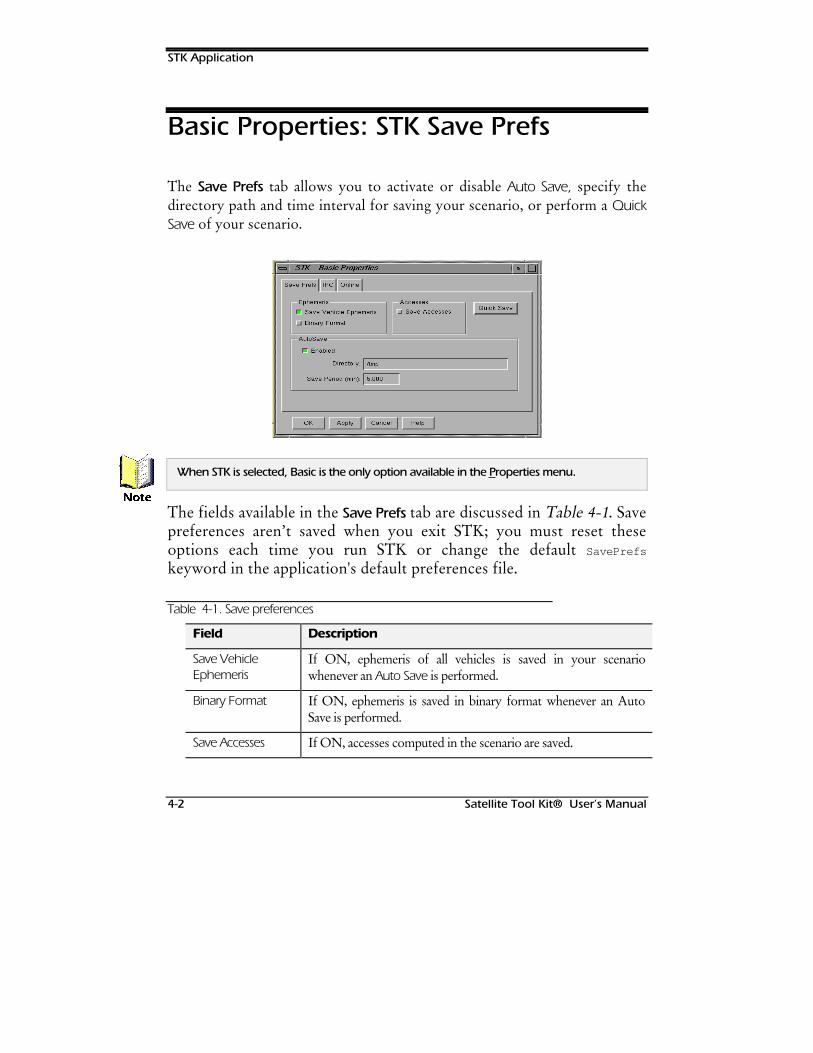
STK Application
4-2 Satellite Tool Kit® User’s Manual
Basic Properties: STK Save Prefs
The Save Prefs tab allows you to activate or disable Auto Save, specify thedirectory path and time interval for saving your scenario, or perform a QuickSave of your scenario.
When STK is selected, Basic is the only option available in the Properties menu.
The fields available in the Save Prefs tab are discussed in Table 4-1. Savepreferences aren’t saved when you exit STK; you must reset theseoptions each time you run STK or change the default SavePrefs
keyword in the application's default preferences file.
Table 4-1. Save preferences
Field Description
Save VehicleEphemeris
If ON, ephemeris of all vehicles is saved in your scenariowhenever an Auto Save is performed.
Binary Format If ON, ephemeris is saved in binary format whenever an AutoSave is performed.
Save Accesses If ON, accesses computed in the scenario are saved.
1RWH
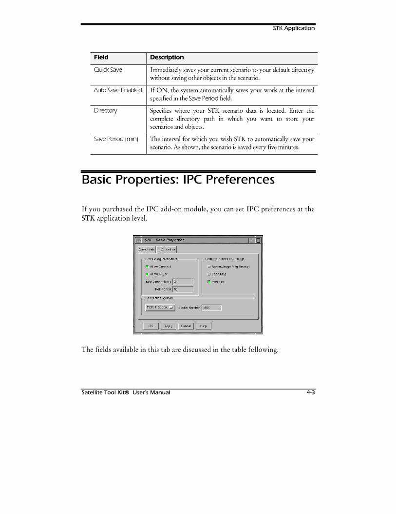
STK Application
Satellite Tool Kit® User’s Manual 4-3
Field Description
Quick Save Immediately saves your current scenario to your default directorywithout saving other objects in the scenario.
Auto Save Enabled If ON, the system automatically saves your work at the intervalspecified in the Save Period field.
Directory Specifies where your STK scenario data is located. Enter thecomplete directory path in which you want to store yourscenarios and objects.
Save Period (min) The interval for which you wish STK to automatically save yourscenario. As shown, the scenario is saved every five minutes.
Basic Properties: IPC Preferences
If you purchased the IPC add-on module, you can set IPC preferences at theSTK application level.
The fields available in this tab are discussed in the table following.
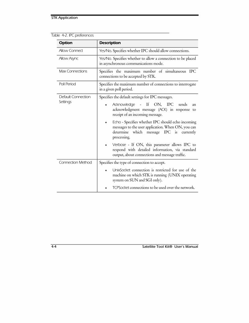
STK Application
4-4 Satellite Tool Kit® User’s Manual
Table 4-2. IPC preferences
Option Description
Allow Connect Yes/No. Specifies whether IPC should allow connections.
Allow Async Yes/No. Specifies whether to allow a connection to be placedin asynchronous communications mode.
Max Connections Specifies the maximum number of simultaneous IPCconnections to be accepted by STK.
Poll Period Specifies the maximum number of connections to interrogatein a given poll period.
Default ConnectionSettings
Specifies the default settings for IPC messages.
♦ Acknowledge - If ON, IPC sends anacknowledgment message (ACK) in response toreceipt of an incoming message.
♦ Echo - Specifies whether IPC should echo incomingmessages to the user application. When ON, you candetermine which message IPC is currentlyprocessing.
♦ Verbose - If ON, this parameter allows IPC torespond with detailed information, via standardoutput, about connections and message traffic.
Connection Method Specifies the type of connection to accept.
♦ UnixSocket connection is restricted for use of themachine on which STK is running (UNIX operatingsystem on SUN and SGI only).
♦ TCPSocket connections to be used over the network.
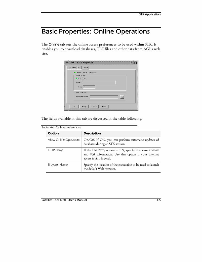
STK Application
Satellite Tool Kit® User’s Manual 4-5
Basic Properties: Online Operations
The Online tab sets the online access preferences to be used within STK. Itenables you to download databases, TLE files and other data from AGI’s website.
The fields available in this tab are discussed in the table following.
Table 4-3. Online preferences
Option Description
Allow Online Operations On/Off. If ON, you can perform automatic updates ofdatabases during an STK session.
HTTP Proxy If the Use Proxy option is ON, specify the correct Serverand Port information. Use this option if your internetaccess is via a firewall.
Browser Name Specify the location of the executable to be used to launchthe default Web browser.

STK Application
4-6 Satellite Tool Kit® User’s Manual
127(6
Satellite Tool Kit® User’s Manual 5-1
5SCENARIOS
Overview
This chapter describes the properties of a scenario and how to manipulatescenarios effectively. A scenario is the object in STK that serves as thecontainer or collection point for all other objects (vehicles, facilities, targets,area targets, planets, stars and sensors). This collection of objects becomesthe outline for a proposed or planned configuration that you need to analyze.You can create and maintain any number of scenarios; the objects you createto populate various scenarios can be used concurrently in some or all of yourscenarios.
Only one scenario can be open at any given time during the STK session.
The scenario serves as the framework for your analysis. As part ofestablishing this framework, you can define an epoch and a time period. Theepoch serves as a reference for all other times in the scenario. The time anddate of the epoch correspond to zero epoch seconds. The time period definesthe general time span (a range of several hours, days or weeks) for analysis. Aredefinition of the time period results in the propagation of the orbits for allsatellites currently loaded in the scenario.
1RWH
Scenarios
5-2 Satellite Tool Kit® User’s Manual
Chapter Contents
Basic Properties: Setting the Time Period......................................................5-2
Basic Properties: Setting Animation Options.................................................5-4
Basic Properties: Setting Units of Measure....................................................5-7
Entering Units in Text Fields ..................................................................5-11
Basic Properties: Setting Default Databases................................................5-11
Basic Properties: Terrain..............................................................................5-12
Adding Terrain Elevation Data..............................................................5-13
Graphics Properties: Global Attributes........................................................5-14
Graphics Properties: Sun Lighting..............................................................5-16
Basic Properties: Setting the TimePeriod
The Time Period tab allows you to specify the Epoch of your scenario and theStart/Stop Times of your scenario in established units.
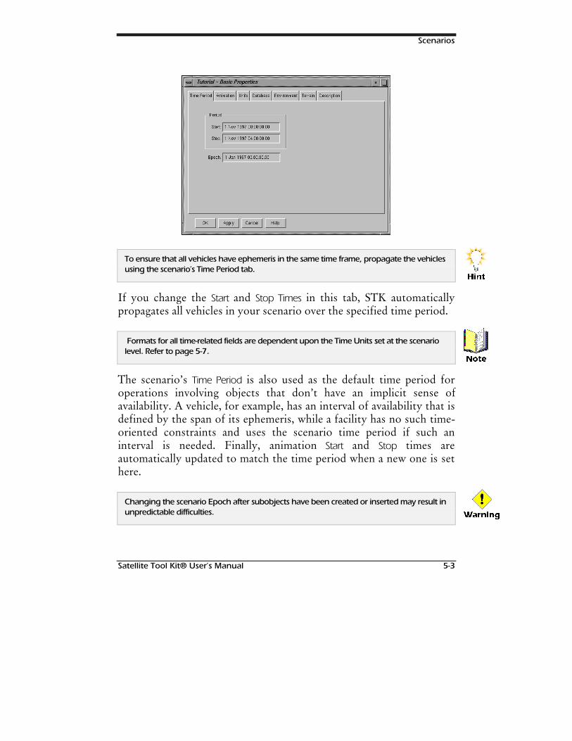
Scenarios
Satellite Tool Kit® User’s Manual 5-3
To ensure that all vehicles have ephemeris in the same time frame, propagate the vehiclesusing the scenario’s Time Period tab.
If you change the Start and Stop Times in this tab, STK automaticallypropagates all vehicles in your scenario over the specified time period.
Formats for all time-related fields are dependent upon the Time Units sset at the scenariolevel. Refer to page 5-7.
The scenario’s Time Period is also used as the default time period foroperations involving objects that don’t have an implicit sense ofavailability. A vehicle, for example, has an interval of availability that isdefined by the span of its ephemeris, while a facility has no such time-oriented constraints and uses the scenario time period if such aninterval is needed. Finally, animation Start and Stop times areautomatically updated to match the time period when a new one is sethere.
Changing the scenario Epoch after subobjects have been created or inserted may result inunpredictable difficulties.
+LQW
1RWH
:DUQLQJ
Scenarios
5-4 Satellite Tool Kit® User’s Manual
If you change the Epoch of a scenario, any subsequent or newly definedvehicles have a default Start Time and Orbit Epoch equal to the new epoch.In addition, relative start times (in epoch seconds) are adjustedaccordingly for all previously defined objects. For new scenarios, thedefault Start Time in the Time Period tab is the scenario Epoch; the StopTime defaults to the Start Time plus four hours.
Table 5-1. Time period options
Field Description
Start Start time for the scenario period.
Stop Stop time for the scenario period.
Epoch Date and time in established units to represent zero epoch seconds ofthe scenario.
Basic Properties: Setting AnimationOptions
The options in the Animation tab allow you to set the Start/Stop/Epoch andTime Step for the scenario.
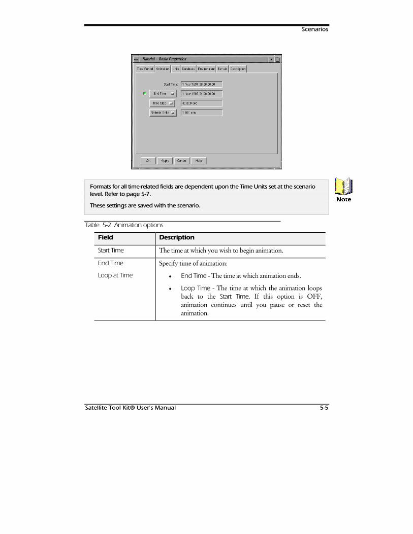
Scenarios
Satellite Tool Kit® User’s Manual 5-5
Formats for all time-related fields are dependent upon the Time Units set at the scenariolevel. Refer to page 5-7.
These settings are saved with the scenario.
Table 5-2. Animation options
Field Description
Start Time The time at which you wish to begin animation.
End Time
Loop at Time
Specify time of animation:
♦ End Time - The time at which animation ends.
♦ Loop Time - The time at which the animation loopsback to the Start Time. If this option is OFF,animation continues until you pause or reset theanimation.
1RWH
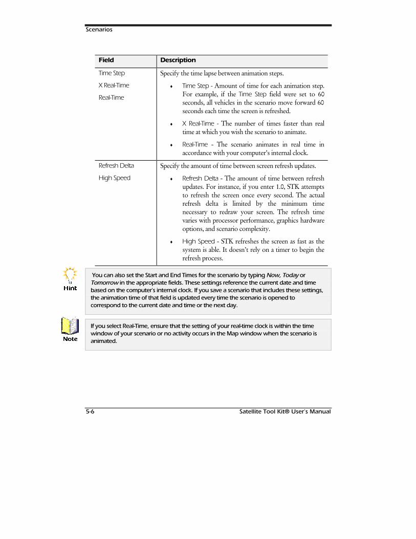
Scenarios
5-6 Satellite Tool Kit® User’s Manual
Field Description
Time Step
X Real-Time
Real-Time
Specify the time lapse between animation steps.
♦ Time Step - Amount of time for each animation step.For example, if the Time Step field were set to 60seconds, all vehicles in the scenario move forward 60seconds each time the screen is refreshed.
♦ X Real-Time - The number of times faster than realtime at which you wish the scenario to animate.
♦ Real-Time - The scenario animates in real time inaccordance with your computer’s internal clock.
Refresh Delta
High Speed
Specify the amount of time between screen refresh updates.
♦ Refresh Delta - The amount of time between refreshupdates. For instance, if you enter 1.0, STK attemptsto refresh the screen once every second. The actualrefresh delta is limited by the minimum timenecessary to redraw your screen. The refresh timevaries with processor performance, graphics hardwareoptions, and scenario complexity.
♦ High Speed - STK refreshes the screen as fast as thesystem is able. It doesn’t rely on a timer to begin therefresh process.
You can also set the Start and End Times for the scenario by typing Now, Today orTomorrow in the appropriate fields. These settings reference the current date and timebased on the computer’s internal clock. If you save a scenario that includes these settings,the animation time of that field is updated every time the scenario is opened tocorrespond to the current date and time or the next day.
If you select Real-Time, ensure that the setting of your real-time clock is within the timewindow of your scenario or no activity occurs in the Map window when the scenario isanimated.
+LQW
1RWH
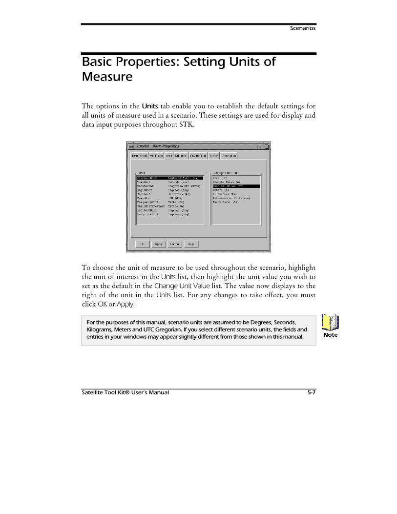
Scenarios
Satellite Tool Kit® User’s Manual 5-7
Basic Properties: Setting Units ofMeasure
The options in the Units tab enable you to establish the default settings forall units of measure used in a scenario. These settings are used for display anddata input purposes throughout STK.
To choose the unit of measure to be used throughout the scenario, highlightthe unit of interest in the Units list, then highlight the unit value you wish toset as the default in the Change Unit Value list. The value now displays to theright of the unit in the Units list. For any changes to take effect, you mustclick OK or Apply.
For the purposes of this manual, scenario units are assumed to be Degrees, Seconds,Kilograms, Meters and UTC Gregorian. If you select different scenario units, the fields andentries in your windows may appear slightly different from those shown in this manual. 1RWH

Scenarios
5-8 Satellite Tool Kit® User’s Manual
Table 5-3. Units options
Field Description
Distance Unit Distance can be displayed in one of the following units:
♦ Feet (ft) Statue Miles (mi)
♦ Nautical miles (nm) Meters (m)
♦ Kilometers (km) Astronomical units (au)
♦ Earth radii (re)
Time Unit Time can be displayed in any one of the following units:
♦ Seconds (sec) Minutes (min)
♦ Hours (hr) Days (day)
Date Format Dates can be displayed in a variety of formats. Available formats are:
♦ Epoch Seconds (EpSec) - Date calculated in seconds relative tothe epoch date specified in the scenario’s Time Period tab.
♦ Epoch Minutes (EpMin) - Date calculated in minutes relative tothe epoch date specified in the scenario’s Time Period tab.
♦ Epoch Hours (EpHr) - Date calculated in hours relative to theepoch date specified in the scenario’s Time Period tab.
♦ Epoch Days (EpDay) - Date calculated in days relative to theepoch date specified in the scenario’s Time Period tab.
♦ Local Gregorian (LCLG) - Local time zone date and timedisplayed in Gregorian format (1 Nov 1997 00:00:00.0000).
♦ UTC Gregorian (UTCG) - Universal Coordinated Time (UTC)date and time displayed in Gregorian format (1 Nov 199700:00:00.0000).
♦ Local Julian (LCLJ) - Local time zone date and time displayedin day of year format (306/97 00:00:00.0000).
♦ UTC Julian (UTCJ) - UTC date and time displayed in day ofyear format (306/ 97 00:00:00.0000).
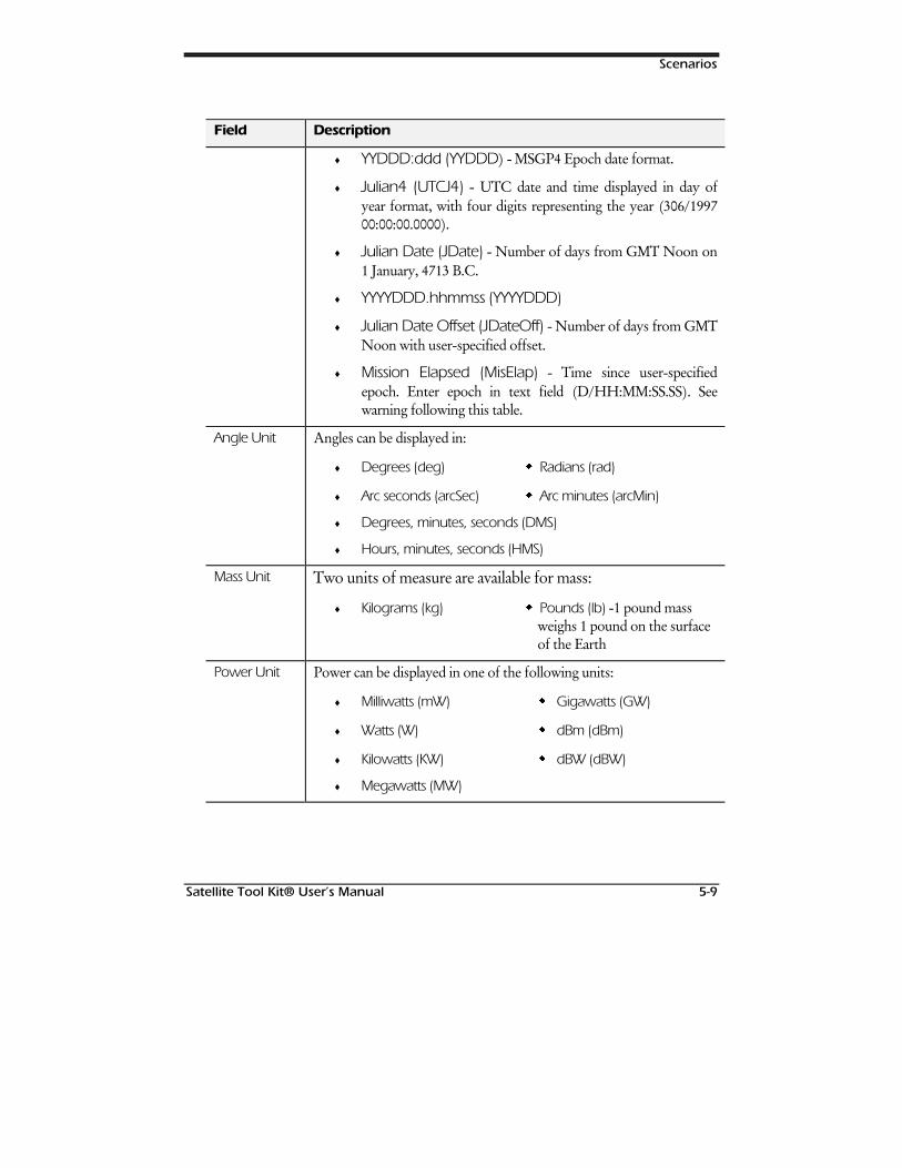
Scenarios
Satellite Tool Kit® User’s Manual 5-9
Field Description
♦ YYDDD:ddd (YYDDD) - MSGP4 Epoch date format.
♦ Julian4 (UTCJ4) - UTC date and time displayed in day ofyear format, with four digits representing the year (306/199700:00:00.0000).
♦ Julian Date (JDate) - Number of days from GMT Noon on1 January, 4713 B.C.
♦ YYYYDDD.hhmmss (YYYYDDD)
♦ Julian Date Offset (JDateOff) - Number of days from GMTNoon with user-specified offset.
♦ Mission Elapsed (MisElap) - Time since user-specifiedepoch. Enter epoch in text field (D/HH:MM:SS.SS). Seewarning following this table.
Angle Unit Angles can be displayed in:
♦ Degrees (deg) Radians (rad)
♦ Arc seconds (arcSec) Arc minutes (arcMin)
♦ Degrees, minutes, seconds (DMS)
♦ Hours, minutes, seconds (HMS)
Mass Unit Two units of measure are available for mass:
♦ Kilograms (kg) Pounds (lb) -1 pound mass weighs 1 pound on the surface of the Earth
Power Unit Power can be displayed in one of the following units:
♦ Milliwatts (mW) Gigawatts (GW)
♦ Watts (W) dBm (dBm)
♦ Kilowatts (KW) dBW (dBW)
♦ Megawatts (MW)
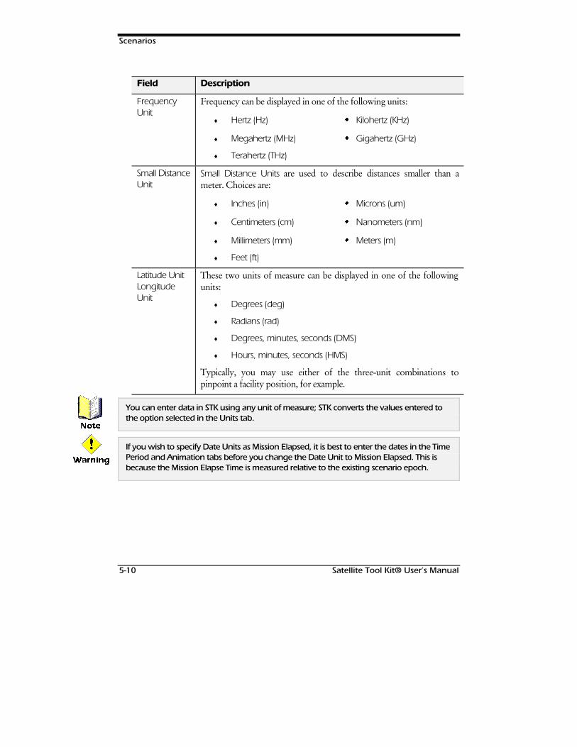
Scenarios
5-10 Satellite Tool Kit® User’s Manual
Field Description
FrequencyUnit
Frequency can be displayed in one of the following units:
♦ Hertz (Hz) Kilohertz (KHz)
♦ Megahertz (MHz) Gigahertz (GHz)
♦ Terahertz (THz)
Small DistanceUnit
Small Distance Units are used to describe distances smaller than ameter. Choices are:
♦ Inches (in) Microns (um)
♦ Centimeters (cm) Nanometers (nm)
♦ Millimeters (mm) Meters (m)
♦ Feet (ft)
Latitude UnitLongitudeUnit
These two units of measure can be displayed in one of the followingunits:
♦ Degrees (deg)
♦ Radians (rad)
♦ Degrees, minutes, seconds (DMS)
♦ Hours, minutes, seconds (HMS)
Typically, you may use either of the three-unit combinations topinpoint a facility position, for example.
You can enter data in STK using any unit of measure; STK converts the values entered tothe option selected in the Units tab.
If you wish to specify Date Units as Mission Elapsed, it is best to enter the dates in the TimePeriod and Animation tabs before you change the Date Unit to Mission Elapsed. This isbecause the Mission Elapse Time is measured relative to the existing scenario epoch.
1RWH
:DUQLQJ
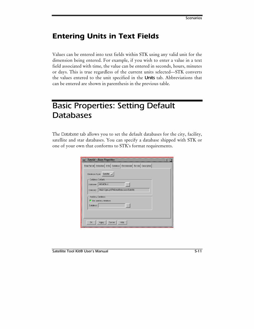
Scenarios
Satellite Tool Kit® User’s Manual 5-11
Entering Units in Text Fields
Values can be entered into text fields within STK using any valid unit for thedimension being entered. For example, if you wish to enter a value in a textfield associated with time, the value can be entered in seconds, hours, minutesor days. This is true regardless of the current units selected—STK convertsthe values entered to the unit specified in the Units tab. Abbreviations thatcan be entered are shown in parenthesis in the previous table.
Basic Properties: Setting DefaultDatabases
The Database tab allows you to set the default databases for the city, facility,satellite and star databases. You can specify a database shipped with STK orone of your own that conforms to STK's format requirements.
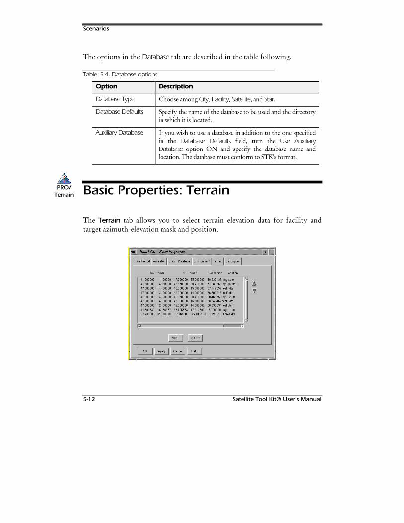
Scenarios
5-12 Satellite Tool Kit® User’s Manual
The options in the Database tab are described in the table following.
Table 5-4. Database options
Option Description
Database Type Choose among City, Facility, Satellite, and Star.
Database Defaults Specify the name of the database to be used and the directoryin which it is located.
Auxiliary Database If you wish to use a database in addition to the one specifiedin the Database Defaults field, turn the Use AuxiliaryDatabase option ON and specify the database name andlocation. The database must conform to STK's format.
Basic Properties: Terrain
The Terrain tab allows you to select terrain elevation data for facility andtarget azimuth-elevation mask and position.
PRO/PRO/TerrainTerrain
Scenarios
Satellite Tool Kit® User’s Manual 5-13
The Terrain module provides precise three-dimensional (3-D) terrainelevation data for the entire globe. When used with STK, Terrain exploitssophisticated multi-dimensional interpolation algorithms to provide accurate360° azimuth/elevation masks for satellite access calculations from any pointon the Earth’s surface. These algorithms also provide altitude information foruser defined facilities and ground based targets. For users of the VO module,Terrain allows a vivid 3-D visual depiction of the Earth’s true surface reliefand its effect on satellite accesses.
The data has a resolution of less than 30 arc-seconds or approximately 1kilometer at the Earth’s surface. In its compressed format, the complete dataset requires over 400 MB of storage. However, the data can be read directlyfrom a CD-ROM without loading it onto your hard disk. This data wasoriginally compiled by the U. S. Geologic Survey from a variety of sourcesaround the world. It has been processed and formatted for optimalperformance with STK.
Use the Up and Down arrows to order the data for level of details andviewing purposes. The order in which the terrain data appears in this list isthe order in which STK searches for terrain data.
Use the Remove button to remove selected terrain data files from the list.
Adding Terrain Elevation Data
Use the Add… button to select terrain elevation data from a CD-ROM oranother location for inclusion in the search list.
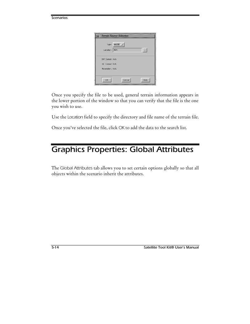
Scenarios
5-14 Satellite Tool Kit® User’s Manual
Once you specify the file to be used, general terrain information appears inthe lower portion of the window so that you can verify that the file is the oneyou wish to use.
Use the Location field to specify the directory and file name of the terrain file.
Once you’ve selected the file, click OK to add the data to the search list.
Graphics Properties: Global Attributes
The Global Attributes tab allows you to set certain options globally so that allobjects within the scenario inherit the attributes.
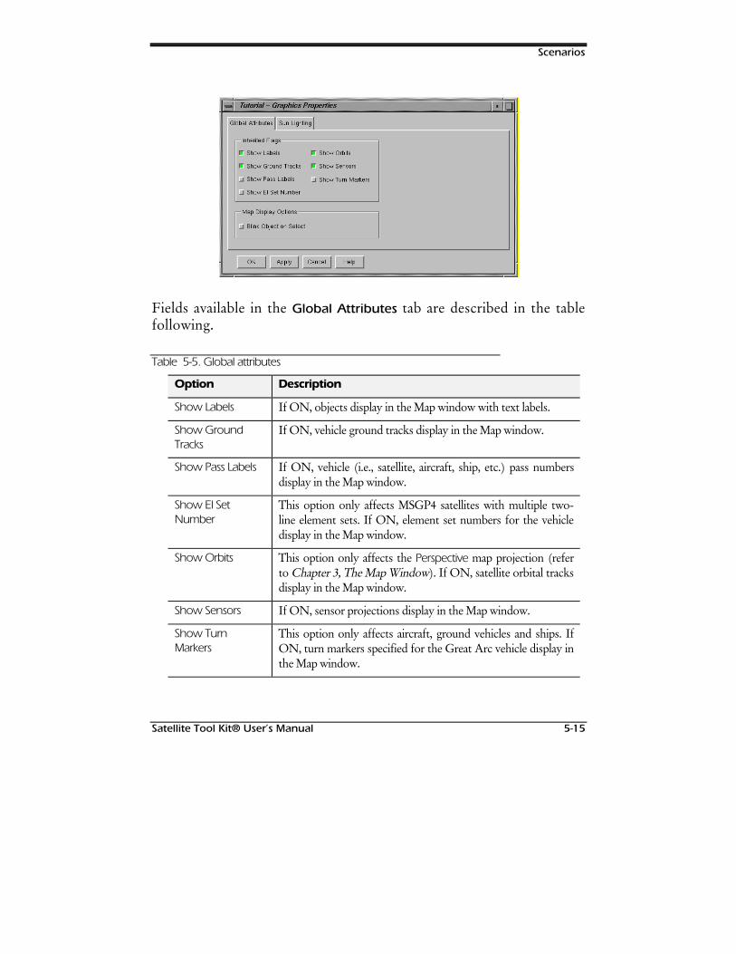
Scenarios
Satellite Tool Kit® User’s Manual 5-15
Fields available in the Global Attributes tab are described in the tablefollowing.
Table 5-5. Global attributes
Option Description
Show Labels If ON, objects display in the Map window with text labels.
Show GroundTracks
If ON, vehicle ground tracks display in the Map window.
Show Pass Labels If ON, vehicle (i.e., satellite, aircraft, ship, etc.) pass numbersdisplay in the Map window.
Show El SetNumber
This option only affects MSGP4 satellites with multiple two-line element sets. If ON, element set numbers for the vehicledisplay in the Map window.
Show Orbits This option only affects the Perspective map projection (referto Chapter 3, The Map Window). If ON, satellite orbital tracksdisplay in the Map window.
Show Sensors If ON, sensor projections display in the Map window.
Show TurnMarkers
This option only affects aircraft, ground vehicles and ships. IfON, turn markers specified for the Great Arc vehicle display inthe Map window.
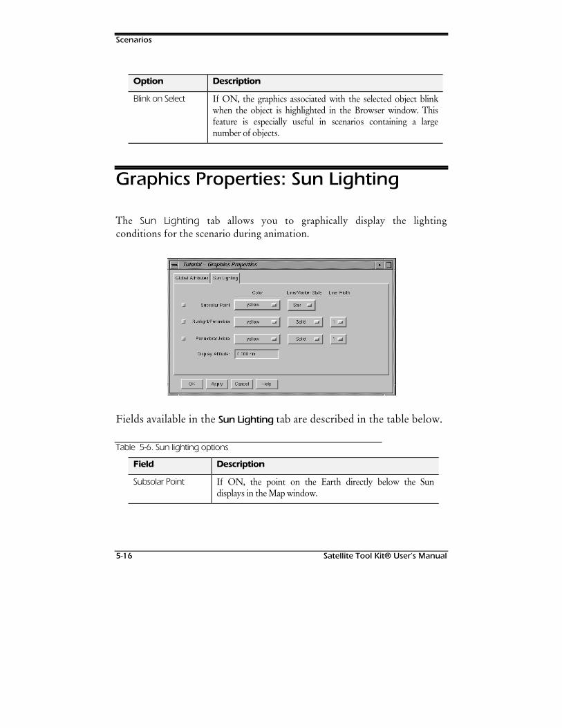
Scenarios
5-16 Satellite Tool Kit® User’s Manual
Option Description
Blink on Select If ON, the graphics associated with the selected object blinkwhen the object is highlighted in the Browser window. Thisfeature is especially useful in scenarios containing a largenumber of objects.
Graphics Properties: Sun Lighting
The Sun Lighting tab allows you to graphically display the lightingconditions for the scenario during animation.
Fields available in the Sun Lighting tab are described in the table below.
Table 5-6. Sun lighting options
Field Description
Subsolar Point If ON, the point on the Earth directly below the Sundisplays in the Map window.
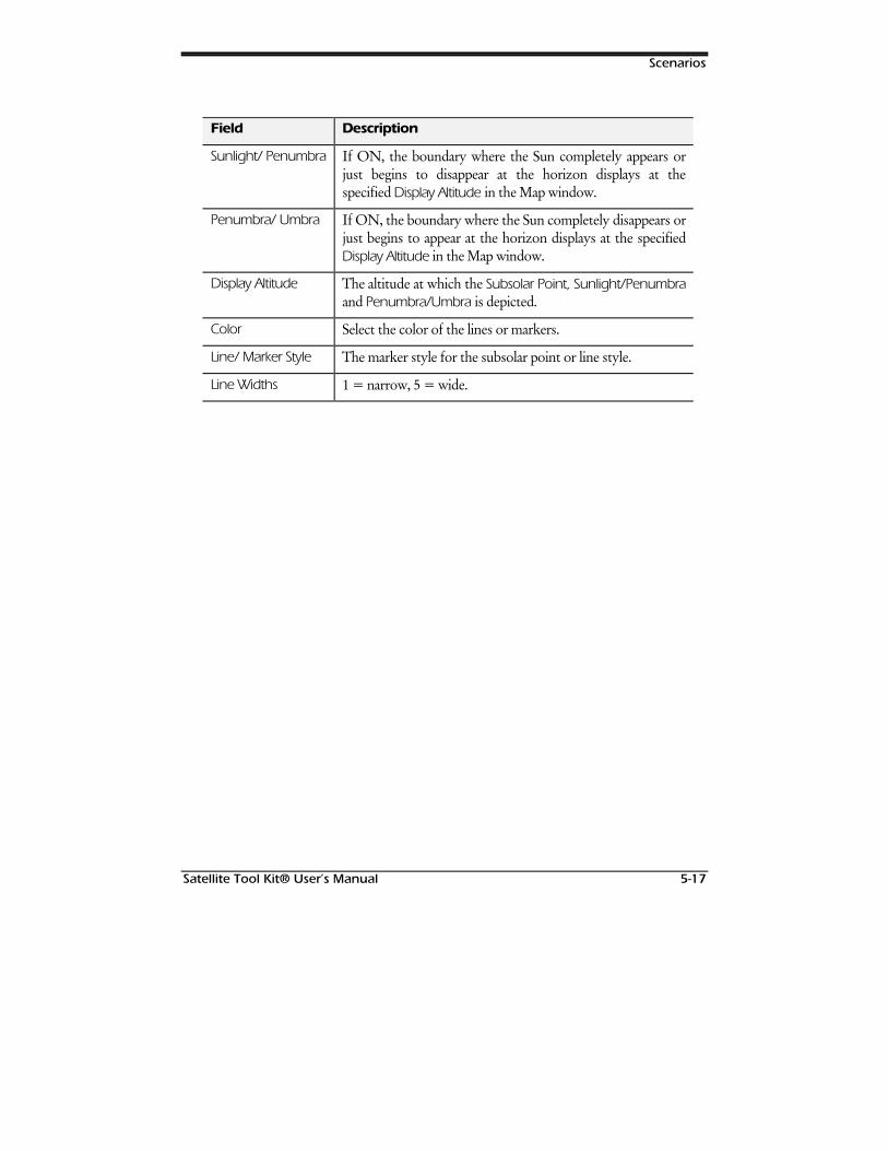
Scenarios
Satellite Tool Kit® User’s Manual 5-17
Field Description
Sunlight/ Penumbra If ON, the boundary where the Sun completely appears orjust begins to disappear at the horizon displays at thespecified Display Altitude in the Map window.
Penumbra/ Umbra If ON, the boundary where the Sun completely disappears orjust begins to appear at the horizon displays at the specifiedDisplay Altitude in the Map window.
Display Altitude The altitude at which the Subsolar Point, Sunlight/Penumbraand Penumbra/Umbra is depicted.
Color Select the color of the lines or markers.
Line/ Marker Style The marker style for the subsolar point or line style.
Line Widths 1 = narrow, 5 = wide.

Scenarios
5-18 Satellite Tool Kit® User’s Manual
127(6
Satellite Tool Kit® User’s Manual 6-1
6SATELLITES
Overview
This chapter describes orbiting satellites, and provides instructions for setting thebasic and graphics properties as well as the access constraints of satellites. It alsoprovides instructions for manipulating satellites to obtain the information you needfor analysis and problem-solving.
Chapter Contents
Basic Properties: Orbit ..................................................................................6-3
Two-Body, J2 Perturbation & J4 Perturbation Propagators ..........................6-3
Orbit Epoch ............................................................................................6-4
Coordinate Epoch ..................................................................................6-4
Coordinate Type.....................................................................................6-4
Coordinate Systems - Standard .............................................................6-12
Coordinate Systems - Advanced Analysis Module.................................6-13
Satellites
6-2 Satellite Tool Kit® User’s Manual
Special Options.....................................................................................6-14
HPOP Propagator (Module).......................................................................6-15
Force Models ........................................................................................6-15
Long-term Orbit Predictor (Module)...........................................................6-18
Force Models ........................................................................................6-18
MSGP4 Propagator ....................................................................................6-22
Managing TLE Sets................................................................................6-24
Custom Propagator (StkExternal) ...............................................................6-27
Basic Properties: Attitude............................................................................6-28
Attitude Type Selection..........................................................................6-29
Orientation Type...................................................................................6-34
Integrated Attitude................................................................................6-35
Target Pointing .....................................................................................6-36
Basic Properties: Pass Break ........................................................................6-38
Basic Properties: Mass.................................................................................6-40
Graphics Properties: Attributes ...................................................................6-41
Graphics Properties: Pass............................................................................6-42
Graphics Properties: Display Times.............................................................6-44
Graphics Properties: Contours ...................................................................6-45
Constraints: Basic .......................................................................................6-47
Constraints: Sun.........................................................................................6-50
Constraints: Temporal ................................................................................6-52
Constraints: Advanced...............................................................................6-54
Satellites
Satellite Tool Kit® User’s Manual 6-3
Basic Properties: Orbit
To generate an orbit for a satellite, open the Basic Properties window for thesatellite. In the Orbit tab, you can use a number of different propagators todefine the satellite’s orbit. At the top of this panel, the Start Time and StopTime fields specify the temporal boundaries of your satellite. The defaultvalues for Start Time and Stop Time are your scenario start and stop times. TheStep Size field specifies the interval between calculated ephemeris outputpoints. The default value is 60 seconds.
The fields available in the bottom portion of the Orbit tab depend on thePropagator chosen. A propagator uses an analytical formulation of the time-dependent motion of a satellite to produce ephemeris or to directly providethe position and velocity of a satellite at a particular time. The propagatorsavailable for a satellite are discussed in the sections following.
Two-Body, J2 Perturbation & J4Perturbation Propagators
The Two-Body, J2 Perturbation and J4 Perturbation propagators all require thesame fields of information to be defined. A Two-Body, or Keplerian motion,propagator considers the Earth to be a point mass with no perturbations. J2Perturbation (first-order) and J4 Perturbation (second-order) propagators accountfor secular variations in the orbit elements due to Earth oblateness. Thesepropagators don’t model atmospheric drag or solar or lunar gravitational forces.
J2 and J4 are zonal harmonic coefficients in an infinite series representation of theEarth’s gravity field. J2 is approximately 1000 times larger than J4 and is a result ofEarth oblateness. The even zonal harmonic coefficients of the gravity field are the
Satellites
6-4 Satellite Tool Kit® User’s Manual
only coefficients that result in secular changes in satellite orbital elements. The J2propagator includes the first-order secular effects of the J2 coefficient while the J4propagator includes the first- and second-order effects of J2 and the first-ordereffects of J4. The J3 coefficient, which produces long period periodic effects, isn'tincluded in either propagator. Since the second-order J2 and the first-order J4secular effects are very small, there is little difference between the orbits generatedby the two propagators.
Orbit Epoch
The Orbit Epoch defines the time at which the established orbit elements (onthe right-hand side of the tab) are true.
Coordinate Epoch
The Coordinate Epoch specifies the epoch of your input coordinate system.Some STK coordinate systems require an epoch in order to be fully defined.If you select a system with a pre-established coordinate epoch (such as J2000or B1950), the Coord Epoch field is disabled.
Coordinate Type
There are six different coordinate types, discussed in the subsectionsfollowing. Each coordinate type is a unique representation of the positionand velocity of the satellite. Some of the individual elements have two ormore options. Fields available in the lower portion of the window depend onthe option you choose for the coordinate type.
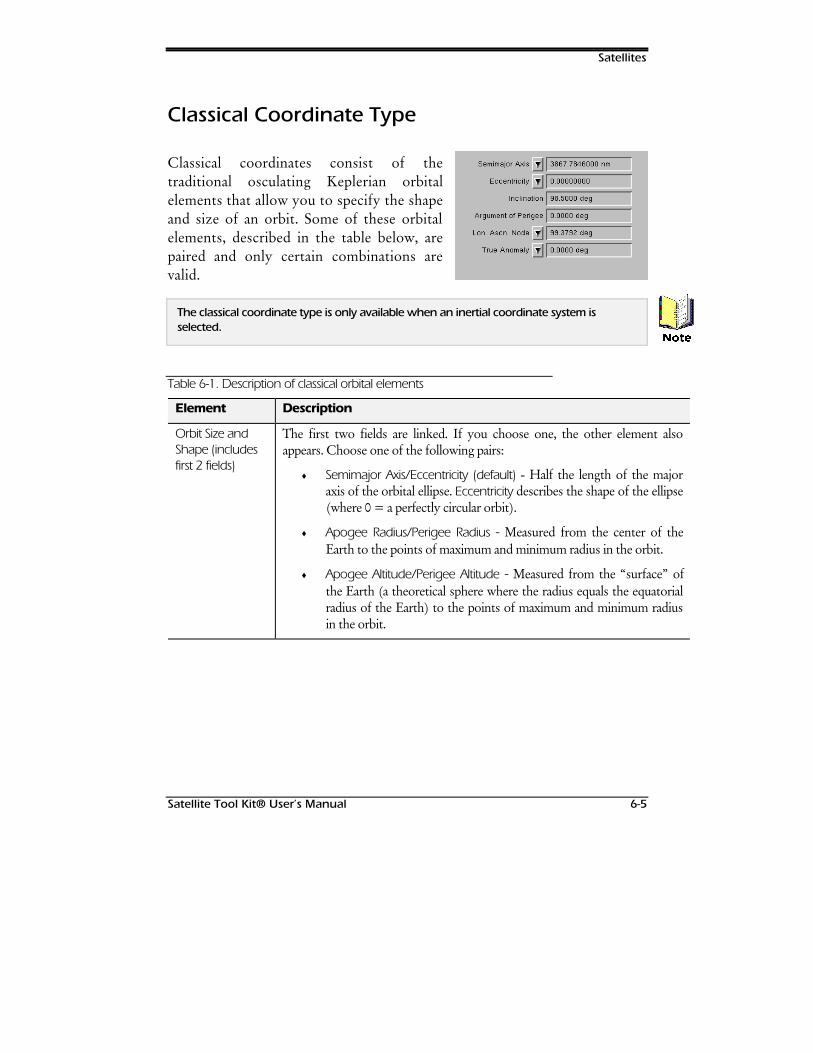
Satellites
Satellite Tool Kit® User’s Manual 6-5
Classical Coordinate Type
Classical coordinates consist of thetraditional osculating Keplerian orbitalelements that allow you to specify the shapeand size of an orbit. Some of these orbitalelements, described in the table below, arepaired and only certain combinations arevalid.
The classical coordinate type is only available when an inertial coordinate system isselected.
Table 6-1. Description of classical orbital elements
Element Description
Orbit Size andShape (includesfirst 2 fields)
The first two fields are linked. If you choose one, the other element alsoappears. Choose one of the following pairs:
♦ Semimajor Axis/Eccentricity (default) - Half the length of the majoraxis of the orbital ellipse. Eccentricity describes the shape of the ellipse(where 0 = a perfectly circular orbit).
♦ Apogee Radius/Perigee Radius - Measured from the center of theEarth to the points of maximum and minimum radius in the orbit.
♦ Apogee Altitude/Perigee Altitude - Measured from the “surface” ofthe Earth (a theoretical sphere where the radius equals the equatorialradius of the Earth) to the points of maximum and minimum radiusin the orbit.
1RWH
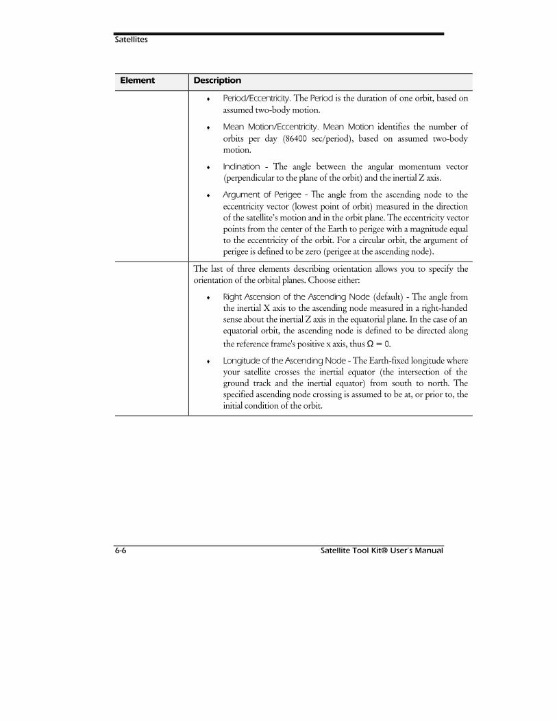
Satellites
6-6 Satellite Tool Kit® User’s Manual
Element Description
♦ Period/Eccentricity. The Period is the duration of one orbit, based onassumed two-body motion.
♦ Mean Motion/Eccentricity. Mean Motion identifies the number oforbits per day (86400 sec/period), based on assumed two-bodymotion.
♦ Inclination - The angle between the angular momentum vector(perpendicular to the plane of the orbit) and the inertial Z axis.
♦ Argument of Perigee - The angle from the ascending node to theeccentricity vector (lowest point of orbit) measured in the directionof the satellite’s motion and in the orbit plane. The eccentricity vectorpoints from the center of the Earth to perigee with a magnitude equalto the eccentricity of the orbit. For a circular orbit, the argument ofperigee is defined to be zero (perigee at the ascending node).
The last of three elements describing orientation allows you to specify theorientation of the orbital planes. Choose either:
♦ Right Ascension of the Ascending Node (default) - The angle fromthe inertial X axis to the ascending node measured in a right-handedsense about the inertial Z axis in the equatorial plane. In the case of anequatorial orbit, the ascending node is defined to be directed alongthe reference frame's positive x axis, thus Ω = 0.
♦ Longitude of the Ascending Node - The Earth-fixed longitude whereyour satellite crosses the inertial equator (the intersection of theground track and the inertial equator) from south to north. Thespecified ascending node crossing is assumed to be at, or prior to, theinitial condition of the orbit.
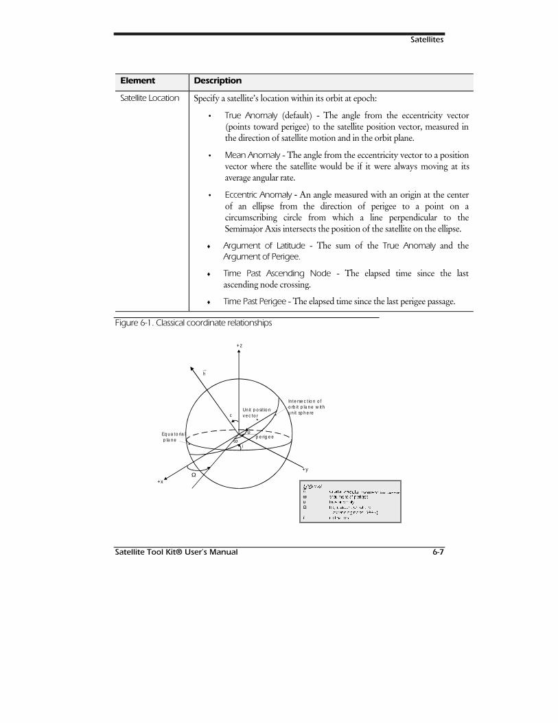
Satellites
Satellite Tool Kit® User’s Manual 6-7
Element Description
Satellite Location Specify a satellite’s location within its orbit at epoch:
• True Anomaly (default) - The angle from the eccentricity vector(points toward perigee) to the satellite position vector, measured inthe direction of satellite motion and in the orbit plane.
• Mean Anomaly - The angle from the eccentricity vector to a positionvector where the satellite would be if it were always moving at itsaverage angular rate.
• Eccentric Anomaly - An angle measured with an origin at the centerof an ellipse from the direction of perigee to a point on acircumscribing circle from which a line perpendicular to theSemimajor Axis intersects the position of the satellite on the ellipse.
♦ Argument of Latitude - The sum of the True Anomaly and theArgument of Perigee.
♦ Time Past Ascending Node - The elapsed time since the lastascending node crossing.
♦ Time Past Perigee - The elapsed time since the last perigee passage.
Figure 6-1. Classical coordinate relationships
//HJHJHHQQGGKK RUERUELWDOLWDO DDQQJJXOXODDUU PRPHPRPHQQWWXXPP YYHHFFRRWUWUω DUJXPHQW RI SHULJHH
υ WUXH DQRPDO\
Ω 5LJKW DVFHQVLRQ RI WKH
DVFHQGLQJ QRGH 5$$1
i LQFOLQDWLRQ
i
+y
+z
Unit positionvecto r
Intersection of orbit p lane w ith unit sphere
+xΩ
ω
υperig eeEquato ria l
p lane
c
h
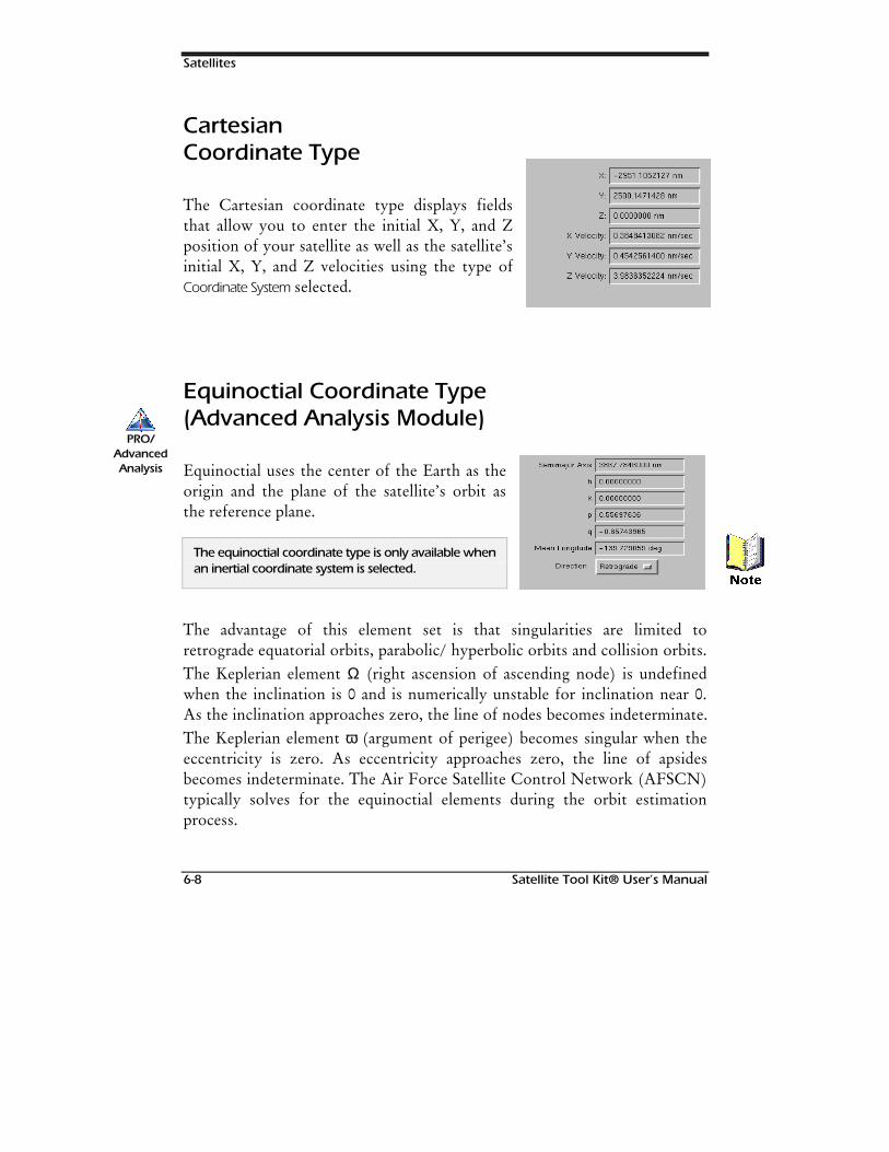
Satellites
6-8 Satellite Tool Kit® User’s Manual
CartesianCoordinate Type
The Cartesian coordinate type displays fieldsthat allow you to enter the initial X, Y, and Zposition of your satellite as well as the satellite’sinitial X, Y, and Z velocities using the type ofCoordinate System selected.
Equinoctial Coordinate Type(Advanced Analysis Module)
Equinoctial uses the center of the Earth as theorigin and the plane of the satellite’s orbit asthe reference plane.
The equinoctial coordinate type is only available whenan inertial coordinate system is selected.
The advantage of this element set is that singularities are limited toretrograde equatorial orbits, parabolic/ hyperbolic orbits and collision orbits.The Keplerian element Ω (right ascension of ascending node) is undefinedwhen the inclination is 0 and is numerically unstable for inclination near 0.As the inclination approaches zero, the line of nodes becomes indeterminate.The Keplerian element ω (argument of perigee) becomes singular when theeccentricity is zero. As eccentricity approaches zero, the line of apsidesbecomes indeterminate. The Air Force Satellite Control Network (AFSCN)typically solves for the equinoctial elements during the orbit estimationprocess.
PRO/AdvancedAnalysis
1RWH
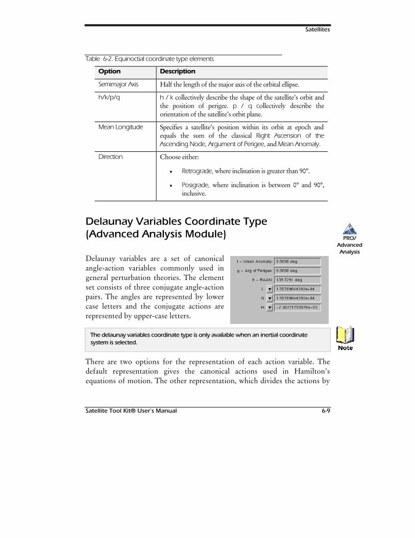
Satellites
Satellite Tool Kit® User’s Manual 6-9
Table 6-2. Equinoctial coordinate type elements
Option Description
Semimajor Axis Half the length of the major axis of the orbital ellipse.
h/k/p/q h / k collectively describe the shape of the satellite’s orbit andthe position of perigee. p / q collectively describe theorientation of the satellite’s orbit plane.
Mean Longitude Specifies a satellite’s position within its orbit at epoch andequals the sum of the classical Right Ascension of theAscending Node, Argument of Perigee, and Mean Anomaly.
Direction Choose either:
♦ Retrograde, where inclination is greater than 90°.
♦ Posigrade, where inclination is between 0° and 90°,inclusive.
Delaunay Variables Coordinate Type(Advanced Analysis Module)
Delaunay variables are a set of canonicalangle-action variables commonly used ingeneral perturbation theories. The elementset consists of three conjugate angle-actionpairs. The angles are represented by lowercase letters and the conjugate actions arerepresented by upper-case letters.
The delaunay variables coordinate type is only available when an inertial coordinatesystem is selected.
There are two options for the representation of each action variable. Thedefault representation gives the canonical actions used in Hamilton’sequations of motion. The other representation, which divides the actions by
PRO/AdvancedAnalysis
1RWH
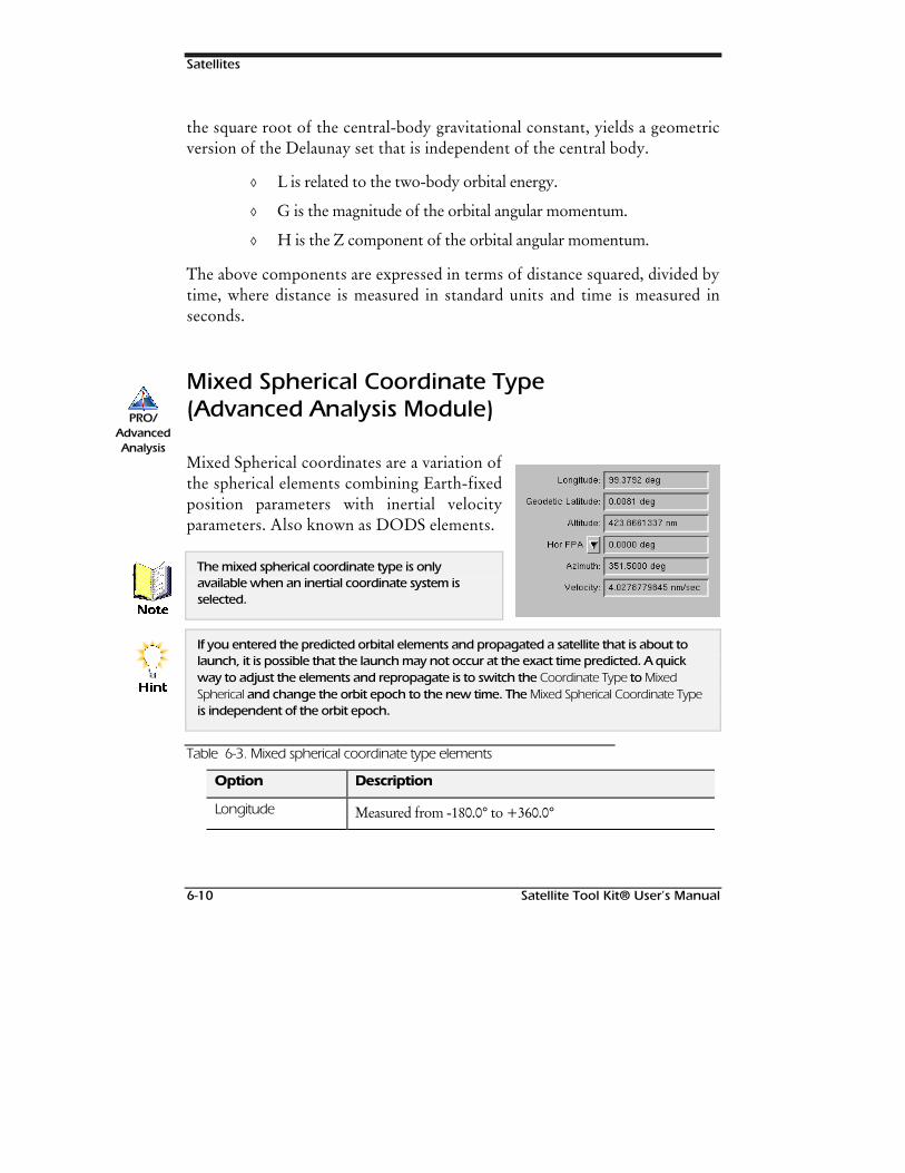
Satellites
6-10 Satellite Tool Kit® User’s Manual
the square root of the central-body gravitational constant, yields a geometricversion of the Delaunay set that is independent of the central body.
◊ L is related to the two-body orbital energy.
◊ G is the magnitude of the orbital angular momentum.
◊ H is the Z component of the orbital angular momentum.
The above components are expressed in terms of distance squared, divided bytime, where distance is measured in standard units and time is measured inseconds.
Mixed Spherical Coordinate Type(Advanced Analysis Module)
Mixed Spherical coordinates are a variation ofthe spherical elements combining Earth-fixedposition parameters with inertial velocityparameters. Also known as DODS elements.
The mixed spherical coordinate type is onlyavailable when an inertial coordinate system isselected.
If you entered the predicted orbital elements and propagated a satellite that is about tolaunch, it is possible that the launch may not occur at the exact time predicted. A quickway to adjust the elements and repropagate is to switch the Coordinate Type to MixedSpherical and change the orbit epoch to the new time. The Mixed Spherical Coordinate Typeis independent of the orbit epoch.
Table 6-3. Mixed spherical coordinate type elements
Option Description
Longitude Measured from -180.0° to +360.0°
PRO/AdvancedAnalysis
1RWH
+LQW
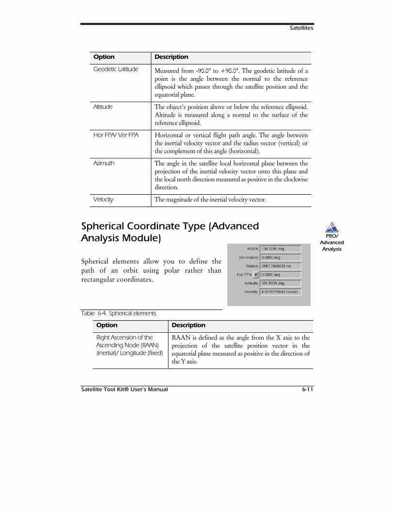
Satellites
Satellite Tool Kit® User’s Manual 6-11
Option Description
Geodetic Latitude Measured from -90.0° to +90.0°. The geodetic latitude of apoint is the angle between the normal to the referenceellipsoid which passes through the satellite position and theequatorial plane.
Altitude The object’s position above or below the reference ellipsoid.Altitude is measured along a normal to the surface of thereference ellipsoid.
Hor FPA/ Ver FPA Horizontal or vertical flight path angle. The angle betweenthe inertial velocity vector and the radius vector (vertical) orthe complement of this angle (horizontal).
Azimuth The angle in the satellite local horizontal plane between theprojection of the inertial velocity vector onto this plane andthe local north direction measured as positive in the clockwisedirection.
Velocity The magnitude of the inertial velocity vector.
Spherical Coordinate Type (AdvancedAnalysis Module)
Spherical elements allow you to define thepath of an orbit using polar rather thanrectangular coordinates.
Table 6-4. Spherical elements
Option Description
Right Ascension of theAscending Node (RAAN)(inertial)/ Longitude (fixed)
RAAN is defined as the angle from the X axis to theprojection of the satellite position vector in theequatorial plane measured as positive in the direction ofthe Y axis.
PRO/AdvancedAnalysis
Satellites
6-12 Satellite Tool Kit® User’s Manual
Option Description
Declination (inertial)/Latitude (fixed)
Declination is defined as the angle between the satelliteposition vector and the inertial equatorial planemeasured as positive toward the positive inertial Z axis.
Radius The magnitude of the satellite position vector.
Flight Path Angle The angle between the velocity vector and the radiusvector (vertical) or the complement of this angle(horizontal).
Azimuth The angle in the satellite local horizontal plane betweenthe projection of the velocity vector onto this plane andthe local north direction measured as positive in theclockwise direction.
Velocity The magnitude of the velocity vector.
Coordinate Systems - Standard
All coordinate systems in STK are a right-handed Cartesian coordinatesystem with the origin at the center of the Earth.
Table 6-5. Standard coordinate systems
Option Description
Fixed X is fixed at 0° longitude, Y is fixed at 90° longitude, andZ is directed toward the north pole.
J2000 X and Z axes point toward the mean vernal equinox andmean rotation axis of the Earth at January 1, 2000 at12:00:00.00 TDT, which corresponds to JD 2451545.0.
Satellites
Satellite Tool Kit® User’s Manual 6-13
Option Description
B1950 X and Z axes point toward the mean vernal equinox andmean rotation axis of the Earth at the beginning of theBesselian year 1950 (when the longitude of the mean Sunis 280.0° measured from the mean equinox) andcorresponds to 31 December 1949 22:09:07.2 or JD2433282.423.
Alignment at Epoch Defines the ECF and ECI systems as in alignment at theOrbit Epoch, using ECF as the baseline and adjustingECI to it. Often used to specify launch trajectories.
Coordinate Systems - AdvancedAnalysis Module
The following coordinate systems are available with the Advanced Analysismodule.
Table 6-6. AAM Coordinate systems
Option Description
Mean of Date X and Z axes point towards the mean vernal equinox and meanrotation axis of the Earth at the Orbit Epoch.
Mean of Epoch X and Z axes point toward the mean vernal equinox and meanrotation axis of the Earth at the Coord Epoch.
True of Date X and Z axes point toward the true vernal equinox and truerotation axis of the Earth at the Orbit Epoch.
True of Epoch X and Z axes point toward the true vernal equinox and truerotation axis of the Earth at the Coord Epoch.
Mean EquinoxTrue Equator
X and Z axes point toward the mean vernal equinox and truerotation axis of the Orbit Epoch.
PRO/AdvancedAnalysis
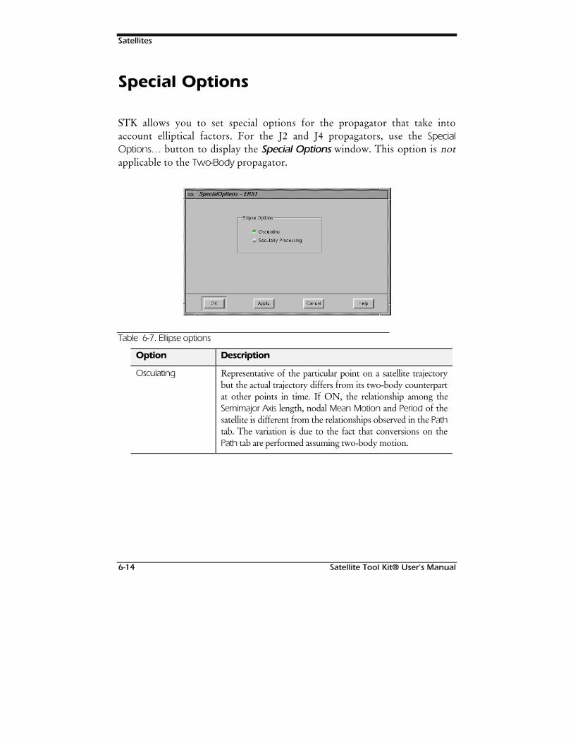
Satellites
6-14 Satellite Tool Kit® User’s Manual
Special Options
STK allows you to set special options for the propagator that take intoaccount elliptical factors. For the J2 and J4 propagators, use the SpecialOptions… button to display the Special Options window. This option is notapplicable to the Two-Body propagator.
Table 6-7. Ellipse options
Option Description
Osculating Representative of the particular point on a satellite trajectorybut the actual trajectory differs from its two-body counterpartat other points in time. If ON, the relationship among theSemimajor Axis length, nodal Mean Motion and Period of thesatellite is different from the relationships observed in the Pathtab. The variation is due to the fact that conversions on thePath tab are performed assuming two-body motion.
Satellites
Satellite Tool Kit® User’s Manual 6-15
Option Description
Secularly Precessing Remains constant in shape and size but changes orientation ina continuous, consistent manner. If ON, the conversionsbetween Semimajor Axis, nodal Period and Mean Motionconsiders the precession of the orbit. In this way, you canaccurately specify nodal periods in the J2 and J4 propagatorsto assist in the design of orbits with strict period requirementsor repeating ground tracks.
HPOP Propagator (Module)
The High-Precision Orbit Propagator (HPOP) can handle circular, elliptical,parabolic and hyperbolic orbits at distances ranging from the surface of theEarth to the orbit of the Moon and beyond, although orbits around theMoon itself are not currently supported.
The HPOP propagator uses the same orbital elements as those required by theTwo-Body, J2 and J4 propagators. For more information about the fieldsavailable for the HPOP propagator, refer to page 6-4 of this chapter.Technical notes about the HPOP propagator are also available as AppendixD of this manual
Force Models
The Force Models… button of the Orbit tab allows you to set advancedoptions for the HPOP propagator.
352
+323
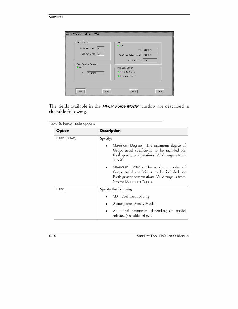
Satellites
6-16 Satellite Tool Kit® User’s Manual
The fields available in the HPOP Force Model window are described inthe table following.
Table 8. Force model options
Option Description
Earth Gravity Specify:
♦ Maximum Degree - The maximum degree ofGeopotential coefficients to be included forEarth gravity computations. Valid range is from0 to 70.
♦ Maximum Order - The maximum order ofGeopotential coefficients to be included forEarth gravity computations. Valid range is from0 to the Maximum Degree.
Drag Specify the following:
♦ CD - Coefficient of drag
♦ Atmosphere Density Model
♦ Additional parameters depending on modelselected (see table below).
Satellites
Satellite Tool Kit® User’s Manual 6-17
Option Description
Solar Radiation Pressure If ON, specify the coefficient of solar radiation pressure.
Third-Body Gravity Choose to include one or both:
♦ Solar Gravity - Effects of solar gravity on thesatellite.
♦ Lunar Gravity - Effects of lunar gravity on thesatellite.
Physical Data Enter the area/mass ratio in square meters per kilogram.
The size of the gravity field used greatly affects the time required to compute the orbit ofthe satellite. For this reason, we recommend that lower degrees and order be specifiedwhen generating orbits for basic studies.
The following atmospheric density models are available for the HPOP forcemodel:
Table 9. Atmospheric Density Models
Option Description
1976 Standard A table lookup model based on the satellite’s altitude. Itsrange of validity is 86km - 1000 km. No additionalparameters need be specified.
Harris-Priester Takes into account a 10.7 cm solar flux level, and hasbeen modified in STK also to take into account diurnalbulge. Its range of validity is 0 - 1000 km, and it requiresspecification of one additional parameter: AverageF10.7.
Jacchia 1971 Computes atmospheric density on the basis of thecomposition of the atmosphere, which depends on thesatellite’s altitude as well as seasonal variation. Its rangeof validity is 100km - 2500 km. Two additionalparameters need to be specified: Average F10.7 andGeomagnetic Index (Kp).
1RWH
Satellites
6-18 Satellite Tool Kit® User’s Manual
Long-term Orbit Predictor (Module)
The Long-term Orbit Predictor (LOP) allows accurate prediction of asatellite’s orbit over many months or years. This is often used for longduration mission design, fuel budget definition and end-of-life studies. Forperformance reasons, it is impractical to compute the long-term variation in asatellite’s orbit using high-accuracy, small-time step, propagators thatcompute a satellite’s position as it moves through its orbit. LOP exploits a“variation of parameters” approach that integrates analytically derivedequations of motion, computing the average effects of perturbations over anorbit. This approach allows large multi-orbit time steps and typicallyimproves computational speed by several hundred times while still offeringhigh fidelity computation of orbit parameters.
LOP implements the 1976 Standard Atmosphere to compute drag effects.Additionally, LOP considers the effects of the Earth’s oblateness (throughJ21), the resonant effects of tesseral harmonics, solar and lunar gravity, andsolar radiation pressure when computing the orbital perturbations. Themodule is based on algorithms developed at NASA’s Jet PropulsionLaboratory.
The LOP propagator uses the same orbital elements as those required by theTwo-Body, J2 and J4 propagators. For more information about the fieldsavailable for the LOP propagator, refer to page 6-4 of this chapter.
Force Models
The Force Models… button of the Orbit tab allows you to set advancedoptions for the LOP propagator.
352
/23
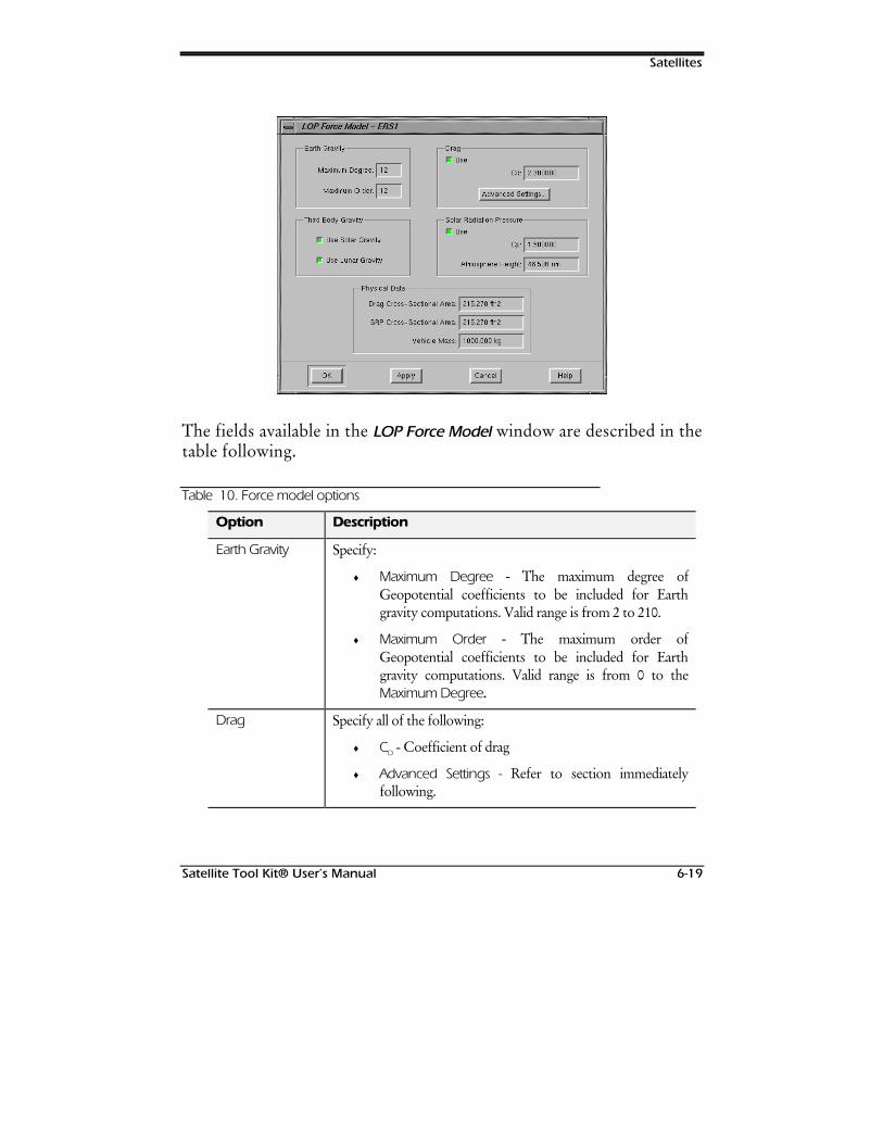
Satellites
Satellite Tool Kit® User’s Manual 6-19
The fields available in the LOP Force Model window are described in thetable following.
Table 10. Force model options
Option Description
Earth Gravity Specify:
♦ Maximum Degree - The maximum degree ofGeopotential coefficients to be included for Earthgravity computations. Valid range is from 2 to 210.
♦ Maximum Order - The maximum order ofGeopotential coefficients to be included for Earthgravity computations. Valid range is from 0 to theMaximum Degree.
Drag Specify all of the following:
♦ CD - Coefficient of drag
♦ Advanced Settings - Refer to section immediatelyfollowing.
Satellites
6-20 Satellite Tool Kit® User’s Manual
Option Description
Third-BodyGravity
Choose to include one or both:
♦ Solar Gravity - Effects of solar gravity on the satellite.
♦ Lunar Gravity - Effects of lunar gravity on the satellite.
Solar RadiationPressure
If ON, specify the coefficient of solar radiation pressure and theatmospheric height.
Physical Data Specify:
♦ Drag Cross-sectional Area - The satellite’s cross-sectional area to be used in atmospheric dragcalculations.
♦ SRP Cross-sectional Area - The satellite’s cross-sectionalarea to be used in solar radiation pressure calculations.
♦ Mass - The mass of the satellite to be used inatmospheric drag and solar radiation pressurecalculations.
The size of the gravity field used greatly affects the time required to compute the orbit ofthe satellite. For this reason, we recommend that lower degrees and order be specifiedwhen generating orbits for basic studies.
Advanced Settings
Use the Advanced Settings… button to further define the drag model to beused for calculations.
1RWH
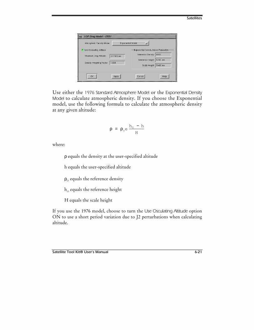
Satellites
Satellite Tool Kit® User’s Manual 6-21
Use either the 1976 Standard Atmosphere Model or the Exponential DensityModel to calculate atmospheric density. If you choose the Exponentialmodel, use the following formula to calculate the atmospheric densityat any given altitude:
ρ ρ=−
oeh h
H0
where:
ρ equals the density at the user-specified altitude
h equals the user-specified altitude
ρO equals the reference density
hO equals the reference height
H equals the scale height
If you use the 1976 model, choose to turn the Use Osculating Altitude optionON to use a short period variation due to J2 perturbations when calculatingaltitude.
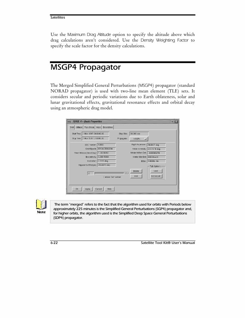
Satellites
6-22 Satellite Tool Kit® User’s Manual
Use the Maximum Drag Altitude option to specify the altitude above whichdrag calculations aren’t considered. Use the Density Weighting Factor tospecify the scale factor for the density calculations.
MSGP4 Propagator
The Merged Simplified General Perturbations (MSGP4) propagator (standardNORAD propagator) is used with two-line mean element (TLE) sets. Itconsiders secular and periodic variations due to Earth oblateness, solar andlunar gravitational effects, gravitational resonance effects and orbital decayusing an atmospheric drag model.
The term “merged” refers to the fact that the algorithm used for orbits with Periods belowapproximately 225 minutes is the Simplified General Perturbations (SGP4) propagator and,for higher orbits, the algorithm used is the Simplified Deep Space General Perturbations(SDP4) propagator.
1RWH
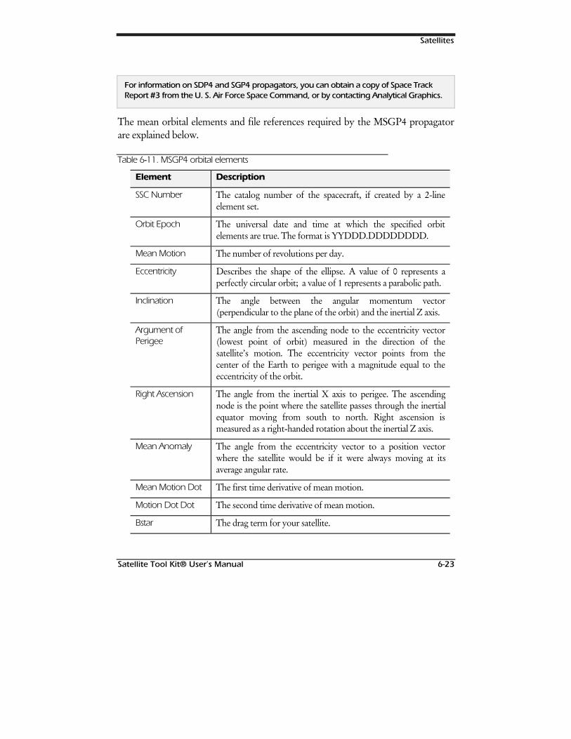
Satellites
Satellite Tool Kit® User’s Manual 6-23
For information on SDP4 and SGP4 propagators, you can obtain a copy of Space TrackReport #3 from the U. S. Air Force Space Command, or by contacting Analytical Graphics.
The mean orbital elements and file references required by the MSGP4 propagatorare explained below.
Table 6--11. MSGP4 orbital elements
Element Description
SSC Number The catalog number of the spacecraft, if created by a 2-lineelement set.
Orbit Epoch The universal date and time at which the specified orbitelements are true. The format is YYDDD.DDDDDDDD.
Mean Motion The number of revolutions per day.
Eccentricity Describes the shape of the ellipse. A value of 0 represents aperfectly circular orbit; a value of 1 represents a parabolic path.
Inclination The angle between the angular momentum vector(perpendicular to the plane of the orbit) and the inertial Z axis.
Argument ofPerigee
The angle from the ascending node to the eccentricity vector(lowest point of orbit) measured in the direction of thesatellite’s motion. The eccentricity vector points from thecenter of the Earth to perigee with a magnitude equal to theeccentricity of the orbit.
Right Ascension The angle from the inertial X axis to perigee. The ascendingnode is the point where the satellite passes through the inertialequator moving from south to north. Right ascension ismeasured as a right-handed rotation about the inertial Z axis.
Mean Anomaly The angle from the eccentricity vector to a position vectorwhere the satellite would be if it were always moving at itsaverage angular rate.
Mean Motion Dot The first time derivative of mean motion.
Motion Dot Dot The second time derivative of mean motion.
Bstar The drag term for your satellite.
Satellites
6-24 Satellite Tool Kit® User’s Manual
The satellite’s SSC Number must be correct to use the TLE Selection feature since TLE searches arebased on the SSC Number.
Managing TLE Sets
At the bottom of the MSGP4 Path tab is a slide bar that can be used to viewthe contents of multiple TLE sets. To view a given TLE set, click the slidebutton and drag the mouse along the slide. The number assigned to theelement set displays directly above the slide. Simply stop the slide at thecorrect number to view the TLE set of your choice.
If you delete an element using the Delete button, make sure that you’re deleting thecorrect element set (i.e., the set deleted is the currently visible one).
Load
You can load or insert a TLE set from a file by using the Load button.
:DUQLQJ
:DUQLQJ

Satellites
Satellite Tool Kit® User’s Manual 6-25
Table 6--12. TLE selection options
Option Description
Load Method Defines how the TLE sets are loaded.
♦ Auto Load - Causes STK to automatically load TLE setscorresponding to the SSC number of the satellite whenthe satellite is loaded.
♦ File Load - Load the selected TLE data and replace allprevious TLE data currently associated with the satellite.
♦ File Insert - Add the selected TLE data but keep previousTLE data currently associated with the satellite.
♦ Online Load - Go directly to Analytical Graphics, Inc.World Wide Web site to download the latest TLE sets.
Max TLE Limit Limit the number of TLE sets that can be saved with the satellite.If the limit set in the Max TLE Limit field is exceeded, STKpurges the oldest TLE data based on the TLE Epoch date.
TLE File Displays the selected TLE file.
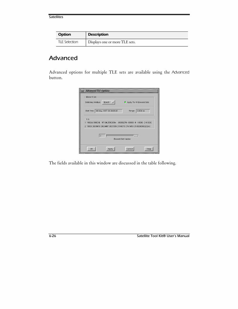
Satellites
6-26 Satellite Tool Kit® User’s Manual
Option Description
TLE Selection Displays one or more TLE sets.
Advanced
Advanced options for multiple TLE sets are available using the Advancedbutton.
The fields available in this window are discussed in the table following.
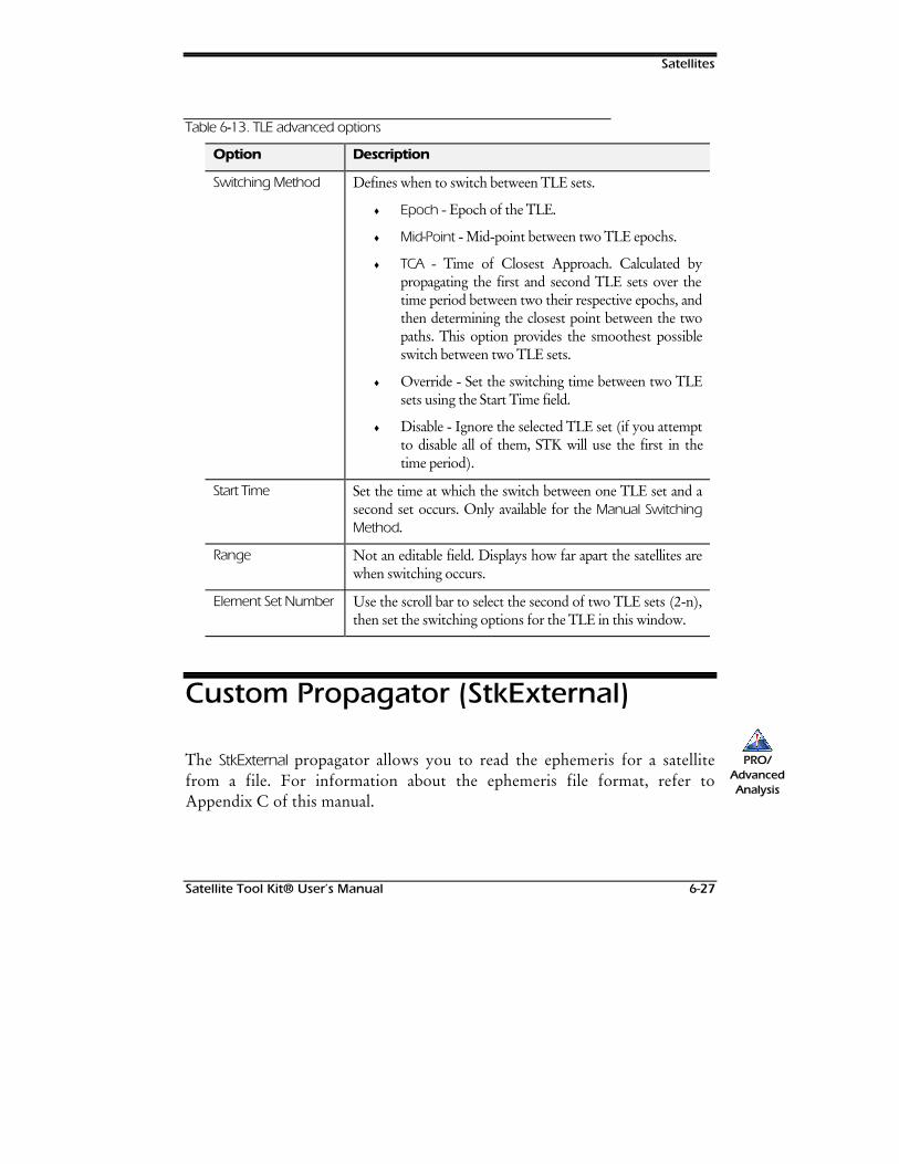
Satellites
Satellite Tool Kit® User’s Manual 6-27
Table 6--13. TLE advanced options
Option Description
Switching Method Defines when to switch between TLE sets.
♦ Epoch - Epoch of the TLE.
♦ Mid-Point - Mid-point between two TLE epochs.
♦ TCA - Time of Closest Approach. Calculated bypropagating the first and second TLE sets over thetime period between two their respective epochs, andthen determining the closest point between the twopaths. This option provides the smoothest possibleswitch between two TLE sets.
♦ Override - Set the switching time between two TLEsets using the Start Time field.
♦ Disable - Ignore the selected TLE set (if you attemptto disable all of them, STK will use the first in thetime period).
Start Time Set the time at which the switch between one TLE set and asecond set occurs. Only available for the Manual SwitchingMethod.
Range Not an editable field. Displays how far apart the satellites arewhen switching occurs.
Element Set Number Use the scroll bar to select the second of two TLE sets (2-n),then set the switching options for the TLE in this window.
Custom Propagator (StkExternal)
The StkExternal propagator allows you to read the ephemeris for a satellitefrom a file. For information about the ephemeris file format, refer toAppendix C of this manual.
PRO/AdvancedAnalysis
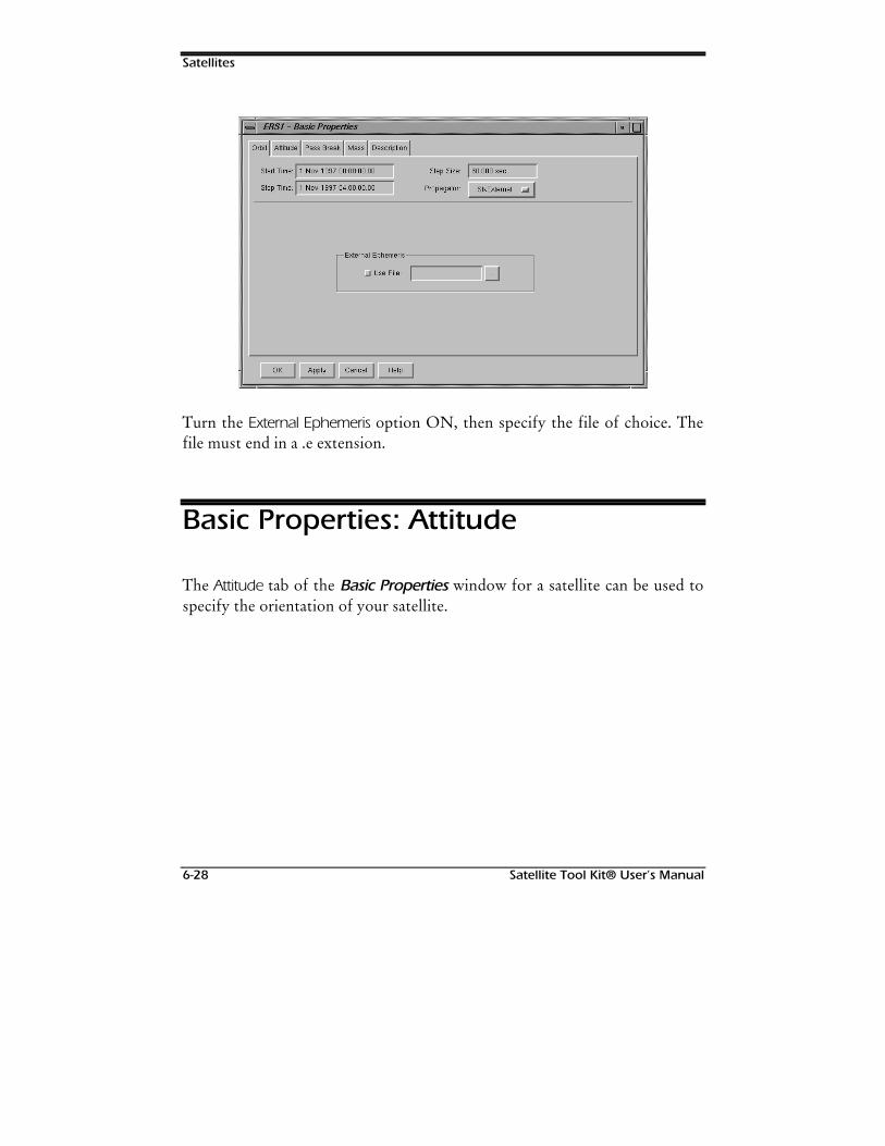
Satellites
6-28 Satellite Tool Kit® User’s Manual
Turn the External Ephemeris option ON, then specify the file of choice. Thefile must end in a .e extension.
Basic Properties: Attitude
The Attitude tab of the Basic Properties window for a satellite can be used tospecify the orientation of your satellite.
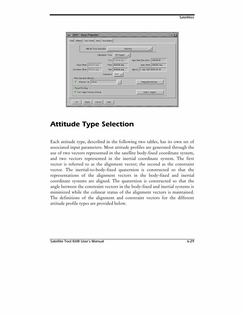
Satellites
Satellite Tool Kit® User’s Manual 6-29
Attitude Type Selection
Each attitude type, described in the following two tables, has its own set ofassociated input parameters. Most attitude profiles are generated through theuse of two vectors represented in the satellite body-fixed coordinate system,and two vectors represented in the inertial coordinate system. The firstvector is referred to as the alignment vector; the second as the constraintvector. The inertial-to-body-fixed quaternion is constructed so that therepresentations of the alignment vectors in the body-fixed and inertialcoordinate systems are aligned. The quaternion is constructed so that theangle between the constraint vectors in the body-fixed and inertial systems isminimized while the colinear status of the alignment vectors is maintained.The definitions of the alignment and constraint vectors for the differentattitude profile types are provided below.
Satellites
6-30 Satellite Tool Kit® User’s Manual
When an axis is constrained, that particular axis attempts to point to the desired locationas close as possible while still maintaining its proper relationship with the other axesdefined in the coordinate system. When an axis is aligned, that axis points directly to thedesired object, forcing the other axes to rotate accordingly.
Attitude Types - Standard
In each of the following attitude types, the satellite’s Z axis is aligned withthe nadir direction:
Table 6--14. Standard attitude types
Attitude Type Description
Nadir alignmentwith ECF velocityconstraint
In this profile, the satellite’s Z axis is aligned with the nadirdirection and the satellite’s X axis is constrained in thedirection of the ECF velocity vector. The Constraint Offsetangle can be used to modify the body-fixed constraint vector.This angle is measured from the X axis direction in a right-handed direction about the Z axis (i.e., to constrain with the Yaxis, set the offset to -90°). The Nadir alignment with ECFvelocity constraint profile may not be appropriate for satellitesin synchronous or highly eccentric orbits since the ECFvelocity vector may be poorly defined and/or alternating indirection. Instead, use the Nadir alignment with ECI velocityconstraints profile.
Nadir alignmentwith ECI velocityconstraint
The satellite’s Z axis is aligned with the nadir direction and theX axis is constrained in the direction of the inertial velocityvector. The Constraint Offset angle can be used to modify thebody-fixed constraint vector. This angle is measured from theX axis direction in a right-handed direction about the Z axis(e.g., to constrain with the Y axis, set the offset to -90°).
The ECF velocity alignment with radial constraint profile is most appropriate for surfacesatellites and aircraft.
1RWH
+LQW
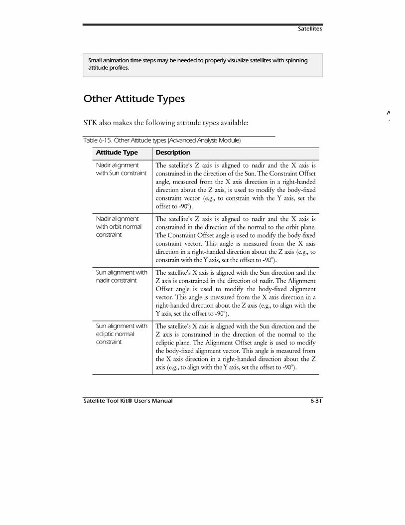
Satellites
Satellite Tool Kit® User’s Manual 6-31
Small animation time steps may be needed to properly visualize satellites with spinningattitude profiles.
Other Attitude Types
STK also makes the following attitude types available:
Table 6--15. Other Attitude types (Advanced Analysis Module)
Attitude Type Description
Nadir alignmentwith Sun constraint
The satellite’s Z axis is aligned to nadir and the X axis isconstrained in the direction of the Sun. The Constraint Offsetangle, measured from the X axis direction in a right-handeddirection about the Z axis, is used to modify the body-fixedconstraint vector (e.g., to constrain with the Y axis, set theoffset to -90°).
Nadir alignmentwith orbit normalconstraint
The satellite’s Z axis is aligned to nadir and the X axis isconstrained in the direction of the normal to the orbit plane.The Constraint Offset angle is used to modify the body-fixedconstraint vector. This angle is measured from the X axisdirection in a right-handed direction about the Z axis (e.g., toconstrain with the Y axis, set the offset to -90°).
Sun alignment withnadir constraint
The satellite’s X axis is aligned with the Sun direction and theZ axis is constrained in the direction of nadir. The AlignmentOffset angle is used to modify the body-fixed alignmentvector. This angle is measured from the X axis direction in aright-handed direction about the Z axis (e.g., to align with theY axis, set the offset to -90°).
Sun alignment withecliptic normalconstraint
The satellite’s X axis is aligned with the Sun direction and theZ axis is constrained in the direction of the normal to theecliptic plane. The Alignment Offset angle is used to modifythe body-fixed alignment vector. This angle is measured fromthe X axis direction in a right-handed direction about the Zaxis (e.g., to align with the Y axis, set the offset to -90°).
AA
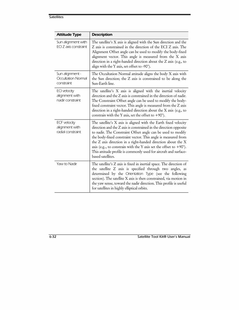
Satellites
6-32 Satellite Tool Kit® User’s Manual
Attitude Type Description
Sun alignment withECI Z axis constraint
The satellite’s X axis is aligned with the Sun direction and theZ axis is constrained in the direction of the ECI Z axis. TheAlignment Offset angle can be used to modify the body-fixedalignment vector. This angle is measured from the X axisdirection in a right-handed direction about the Z axis (e.g., toalign with the Y axis, set offset to -90°).
Sun alignment -Occultation Normalconstraint
The Occultation Normal attitude aligns the body X axis withthe Sun direction; the Z axis is constrained to be along theSun-Earth line.
ECI velocityalignment withnadir constraint
The satellite’s X axis is aligned with the inertial velocitydirection and the Z axis is constrained in the direction of nadir.The Constraint Offset angle can be used to modify the body-fixed constraint vector. This angle is measured from the Z axisdirection in a right-handed direction about the X axis (e.g., toconstrain with the Y axis, set the offset to +90°).
ECF velocityalignment withradial constraint
The satellite’s X axis is aligned with the Earth fixed velocitydirection and the Z axis is constrained in the direction oppositeto nadir. The Constraint Offset angle can be used to modifythe body-fixed constraint vector. This angle is measured fromthe Z axis direction in a right-handed direction about the Xaxis (e.g.., to constrain with the Y axis set the offset to +90°).This attitude profile is commonly used for aircraft and surface-based satellites.
Yaw to Nadir The satellite’s Z axis is fixed in inertial space. The direction ofthe satellite Z axis is specified through two angles, asdetermined by the Orientation Type (see the followingsection). The satellite X axis is then constrained, via motion inthe yaw sense, toward the nadir direction. This profile is usefulfor satellites in highly elliptical orbits.
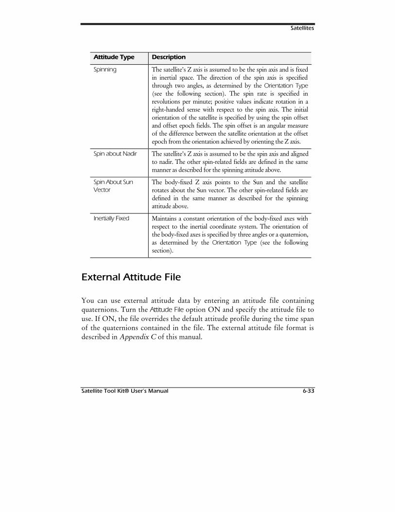
Satellites
Satellite Tool Kit® User’s Manual 6-33
Attitude Type Description
Spinning The satellite’s Z axis is assumed to be the spin axis and is fixedin inertial space. The direction of the spin axis is specifiedthrough two angles, as determined by the Orientation Type(see the following section). The spin rate is specified inrevolutions per minute; positive values indicate rotation in aright-handed sense with respect to the spin axis. The initialorientation of the satellite is specified by using the spin offsetand offset epoch fields. The spin offset is an angular measureof the difference between the satellite orientation at the offsetepoch from the orientation achieved by orienting the Z axis.
Spin about Nadir The satellite’s Z axis is assumed to be the spin axis and alignedto nadir. The other spin-related fields are defined in the samemanner as described for the spinning attitude above.
Spin About SunVector
The body-fixed Z axis points to the Sun and the satelliterotates about the Sun vector. The other spin-related fields aredefined in the same manner as described for the spinningattitude above.
Inertially Fixed Maintains a constant orientation of the body-fixed axes withrespect to the inertial coordinate system. The orientation ofthe body-fixed axes is specified by three angles or a quaternion,as determined by the Orientation Type (see the followingsection).
External Attitude File
You can use external attitude data by entering an attitude file containingquaternions. Turn the Attitude File option ON and specify the attitude file touse. If ON, the file overrides the default attitude profile during the time spanof the quaternions contained in the file. The external attitude file format isdescribed in Appendix C of this manual.
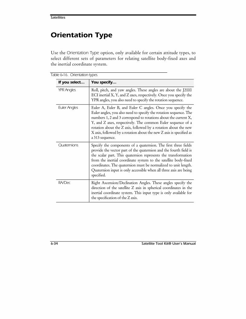
Satellites
6-34 Satellite Tool Kit® User’s Manual
Orientation Type
Use the Orientation Type option, only available for certain attitude types, toselect different sets of parameters for relating satellite body-fixed axes andthe inertial coordinate system.
Table 6--16. Orientation types
If you select… You specify…
YPR Angles Roll, pitch, and yaw angles. These angles are about the J2000ECI inertial X, Y, and Z axes, respectively. Once you specify theYPR angles, you also need to specify the rotation sequence.
Euler Angles Euler A, Euler B, and Euler C angles. Once you specify theEuler angles, you also need to specify the rotation sequence. Thenumbers 1, 2 and 3 correspond to rotations about the current X,Y, and Z axes, respectively. The common Euler sequence of arotation about the Z axis, followed by a rotation about the newX axis, followed by a rotation about the new Z axis is specified asa 313 sequence.
Quaternions Specify the components of a quaternion. The first three fieldsprovide the vector part of the quaternion and the fourth field isthe scalar part. This quaternion represents the transformationfrom the inertial coordinate system to the satellite body-fixedcoordinates. The quaternion must be normalized to unit length.Quaternion input is only accessible when all three axis are beingspecified.
RA/Dec Right Ascension/Declination Angles. These angles specify thedirection of the satellite Z axis in spherical coordinates in theinertial coordinate system. This input type is only available forthe specification of the Z axis.
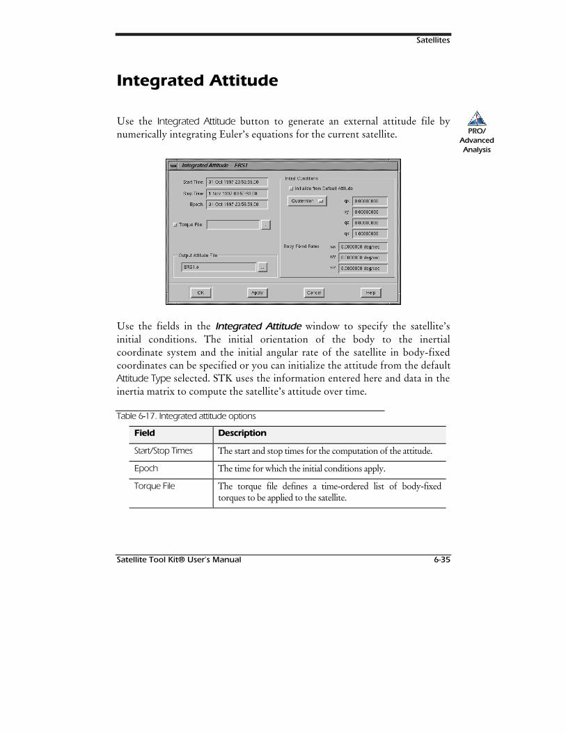
Satellites
Satellite Tool Kit® User’s Manual 6-35
Integrated Attitude
Use the Integrated Attitude button to generate an external attitude file bynumerically integrating Euler’s equations for the current satellite.
Use the fields in the Integrated Attitude window to specify the satellite’sinitial conditions. The initial orientation of the body to the inertialcoordinate system and the initial angular rate of the satellite in body-fixedcoordinates can be specified or you can initialize the attitude from the defaultAttitude Type selected. STK uses the information entered here and data in theinertia matrix to compute the satellite’s attitude over time.
Table 6--17. Integrated attitude options
Field Description
Start/Stop Times The start and stop times for the computation of the attitude.
Epoch The time for which the initial conditions apply.
Torque File The torque file defines a time-ordered list of body-fixedtorques to be applied to the satellite.
PRO/AdvancedAnalysis
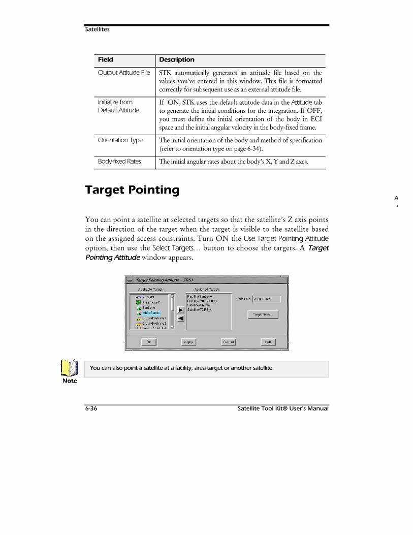
Satellites
6-36 Satellite Tool Kit® User’s Manual
Field Description
Output Attitude File STK automatically generates an attitude file based on thevalues you’ve entered in this window. This file is formattedcorrectly for subsequent use as an external attitude file.
Initialize fromDefault Attitude
If ON, STK uses the default attitude data in the Attitude tabto generate the initial conditions for the integration. If OFF,you must define the initial orientation of the body in ECIspace and the initial angular velocity in the body-fixed frame.
Orientation Type The initial orientation of the body and method of specification(refer to orientation type on page 6-34).
Body-fixed Rates The initial angular rates about the body’s X, Y and Z axes.
Target Pointing
You can point a satellite at selected targets so that the satellite’s Z axis pointsin the direction of the target when the target is visible to the satellite basedon the assigned access constraints. Turn ON the Use Target Pointing Attitudeoption, then use the Select Targets… button to choose the targets. A TargetPointing Attitude window appears.
You can also point a satellite at a facility, area target or another satellite.
AA
1RWH
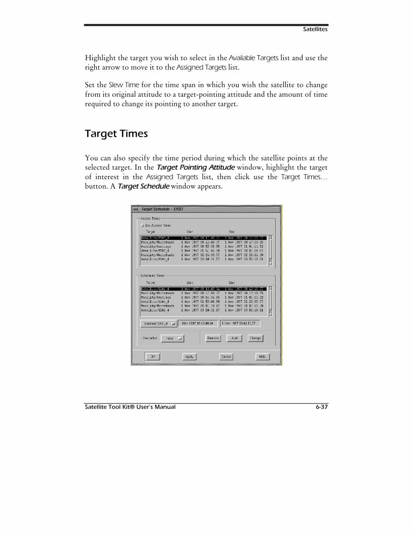
Satellites
Satellite Tool Kit® User’s Manual 6-37
Highlight the target you wish to select in the Available Targets list and use theright arrow to move it to the Assigned Targets list.
Set the Slew Time for the time span in which you wish the satellite to changefrom its original attitude to a target-pointing attitude and the amount of timerequired to change its pointing to another target.
Target Times
You can also specify the time period during which the satellite points at theselected target. In the Target Pointing Attitude window, highlight the targetof interest in the Assigned Targets list, then click use the Target Times…button. A Target Schedule window appears.
Satellites
6-38 Satellite Tool Kit® User’s Manual
You can choose to use the access times determined between the satellite andthe selected target by turning the Use Access Times option ON.
If you wish to define other times during which the satellite should orienttoward a selected target, enter the Start and Stop Times , then use the Addbutton. To modify a time listed in the Scheduled Times list, highlight the timeperiod of interest so that the Start and Stop Times display in the text boxes,then modify the values and use the Change button.
You can also choose whether the time intervals should be “deconflicted,” ormodified so that time periods set don’t overlap. If the Deconflict field is set toAutomatic, STK automatically modifies all time intervals during which anoverlap occurs so that the intervals are further segmented to avoid overlap. Ifthe field is set to None, no changes are made to time interval overlaps. If thefield is set to Manual, when an overlap occurs in the time interval list, anAcknowledge window appears when you click the OK or Apply button toalert you to the fact that the overlap exists. It is then your decision whetherto set the Deconflict field to Automatic so that the overlap is fixed, change thetime intervals yourself by modifying the appropriate entries in the list box, orignore the message and continue. If you ignore the message, the satellitepoints at the first target until the target is no longer in sight.
Basic Properties: Pass Break
The Pass Break tab of the Basic Properties window for satellites allows you tospecify the event that defines the boundary between passes (or revolutions)of an orbiting satellite.
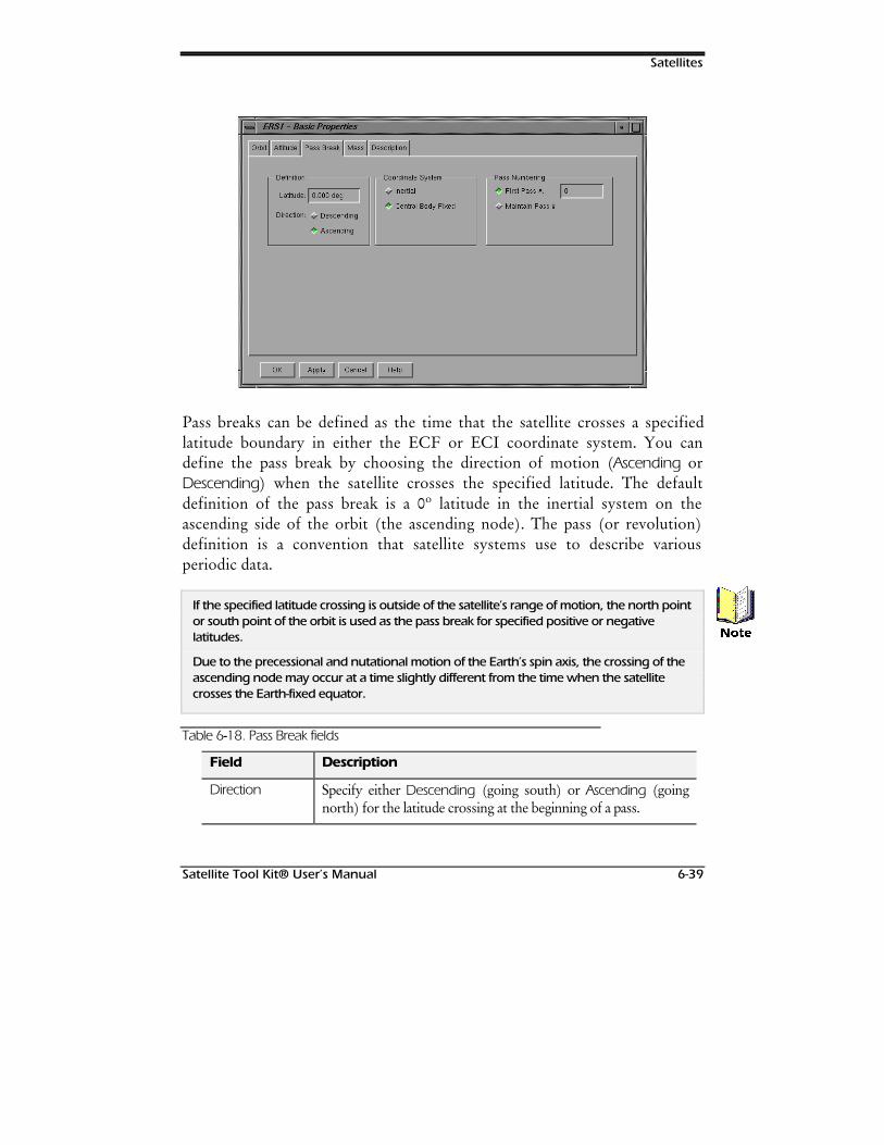
Satellites
Satellite Tool Kit® User’s Manual 6-39
Pass breaks can be defined as the time that the satellite crosses a specifiedlatitude boundary in either the ECF or ECI coordinate system. You candefine the pass break by choosing the direction of motion (Ascending orDescending) when the satellite crosses the specified latitude. The defaultdefinition of the pass break is a 0º latitude in the inertial system on theascending side of the orbit (the ascending node). The pass (or revolution)definition is a convention that satellite systems use to describe variousperiodic data.
If the specified latitude crossing is outside of the satellite’s range of motion, the north pointor south point of the orbit is used as the pass break for specified positive or negativelatitudes.
Due to the precessional and nutational motion of the Earth’s spin axis, the crossing of theascending node may occur at a time slightly different from the time when the satellitecrosses the Earth-fixed equator.
Table 6--18. Pass Break fields
Field Description
Direction Specify either Descending (going south) or Ascending (goingnorth) for the latitude crossing at the beginning of a pass.
1RWH
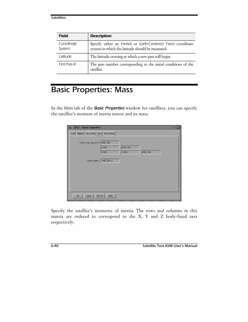
Satellites
6-40 Satellite Tool Kit® User’s Manual
Field Description
CoordinateSystem
Specify either an Inertial or Earth-Centered Fixed coordinatesystem in which the latitude should be measured.
Latitude The latitude crossing at which a new pass will begin.
First Pass # The pass number corresponding to the initial conditions of thesatellite.
Basic Properties: Mass
In the Mass tab of the Basic Properties window for satellites, you can specifythe satellite’s moment of inertia tensor and its mass.
Specify the satellite’s moments of inertia. The rows and columns in thismatrix are ordered to correspond to the X, Y and Z body-fixed axesrespectively.
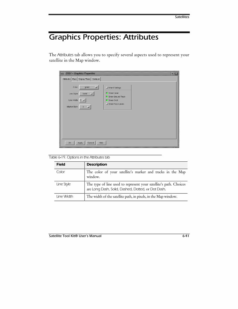
Satellites
Satellite Tool Kit® User’s Manual 6-41
Graphics Properties: Attributes
The Attributes tab allows you to specify several aspects used to represent yoursatellite in the Map window.
Table 6--19. Options in the Attributes tab
Field Description
Color The color of your satellite’s marker and tracks in the Mapwindow.
Line Style The type of line used to represent your satellite’s path. Choicesare Long Dash, Solid, Dashed, Dotted, or Dot Dash.
Line Width The width of the satellite path, in pixels, in the Map window.
Satellites
6-42 Satellite Tool Kit® User’s Manual
Field Description
Marker Style The type of marker used to represent your satellite’s currentposition. Choices include Square, Point, Plus Sign, Star, Circle, oran X, in addition to pictures from STK object icons and othergraphical images. You can also add a custom marker by creating apixmap file with a .marker extension and saving it to your<Home>/stkData/Pixmaps directory. pixmaps can be anysize. Once created, custom markers are available in the MarkerStyle list.
Inherit Settings If the Inherit Settings feature is ON, the satellite’s label, groundtrack, pass label and orbit track are displayed in accordance withthe scenario’s graphic attributes, set through the Attributes tab ofthe scenario’s Graphic Properties window. If this feature isOFF, the options available in this field override those set at thescenario level. The Show Pass Labels setting doesn’t appear whenthe satellite is defined as a rocket, regardless of whether InheritSettings are ON or OFF. The Show Elset Numbers optionappears only if satellite was propagated with the MSGP4propagator.
Graphics Properties: Pass
The fields in this tab allow you to control the display of satellite pass graphicsin the Map window.
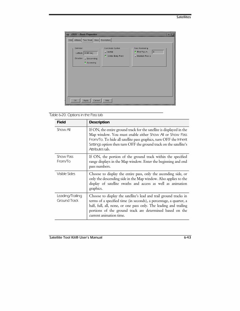
Satellites
Satellite Tool Kit® User’s Manual 6-43
Table 6--20. Options in the Pass tab
Field Description
Show All If ON, the entire ground track for the satellite is displayed in theMap window. You must enable either Show All or Show PassFrom/To. To hide all satellite pass graphics, turn OFF the InheritSettings option then turn OFF the ground track on the satellite’sAttributes tab.
Show PassFrom/To
If ON, the portion of the ground track within the specifiedrange displays in the Map window. Enter the beginning and endpass numbers.
Visible Sides Choose to display the entire pass, only the ascending side, oronly the descending side in the Map window. Also applies to thedisplay of satellite swaths and access as well as animationgraphics.
Leading/TrailingGround Track
Choose to display the satellite’s lead and trail ground tracks interms of a specified time (in seconds), a percentage, a quarter, ahalf, full, all, none, or one pass only. The leading and trailingportions of the ground track are determined based on thecurrent animation time.
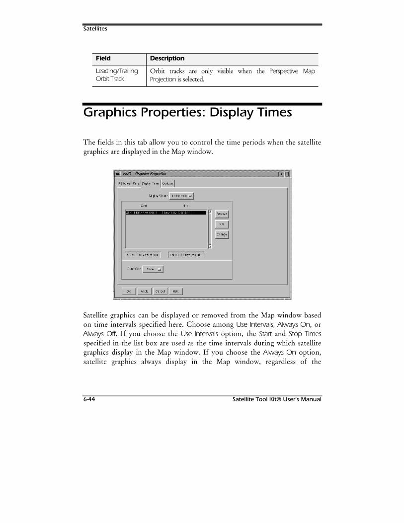
Satellites
6-44 Satellite Tool Kit® User’s Manual
Field Description
Leading/TrailingOrbit Track
Orbit tracks are only visible when the Perspective MapProjection is selected.
Graphics Properties: Display Times
The fields in this tab allow you to control the time periods when the satellitegraphics are displayed in the Map window.
Satellite graphics can be displayed or removed from the Map window basedon time intervals specified here. Choose among Use Intervals, Always On, orAlways Off. If you choose the Use Intervals option, the Start and Stop Timesspecified in the list box are used as the time intervals during which satellitegraphics display in the Map window. If you choose the Always On option,satellite graphics always display in the Map window, regardless of the
Satellites
Satellite Tool Kit® User’s Manual 6-45
intervals specified in the list box. If you choose the Always Off option,satellite graphics never display in the Map window.
To specify the times during which satellite graphics should display in theMap window, use the Add button. To modify a time interval in the list box,highlight the time period of interest and use the Change button. To remove atime period, use the Remove button.
You can also choose whether the time intervals should be “deconflicted,” ormodified so that time periods don’t overlap. If the Deconflict option is set toAutomatic, STK automatically modifies all time intervals during which anoverlap occurs so that the intervals are further segmented to avoid overlap. Ifthe option is set to None, no changes are made to time interval overlaps. Ifthe option is set to Manual, when an overlap occurs in the time interval list,an Acknowledge window appears when you click the OK or Apply button toalert you to the fact that overlap(s) exists. It is then your decision whether toset the Deconflict field to Automatic so that overlap(s) are fixed, change thetime intervals yourself by modifying the appropriate entries in the list box, orignore the message and continue.
The time intervals only apply to the graphical display of the satellite—they don’t affectaccess computations.
Graphics Properties: Contours
The fields in this tab allow you to control the display of elevation anglecontours in the Map window.
1RWH
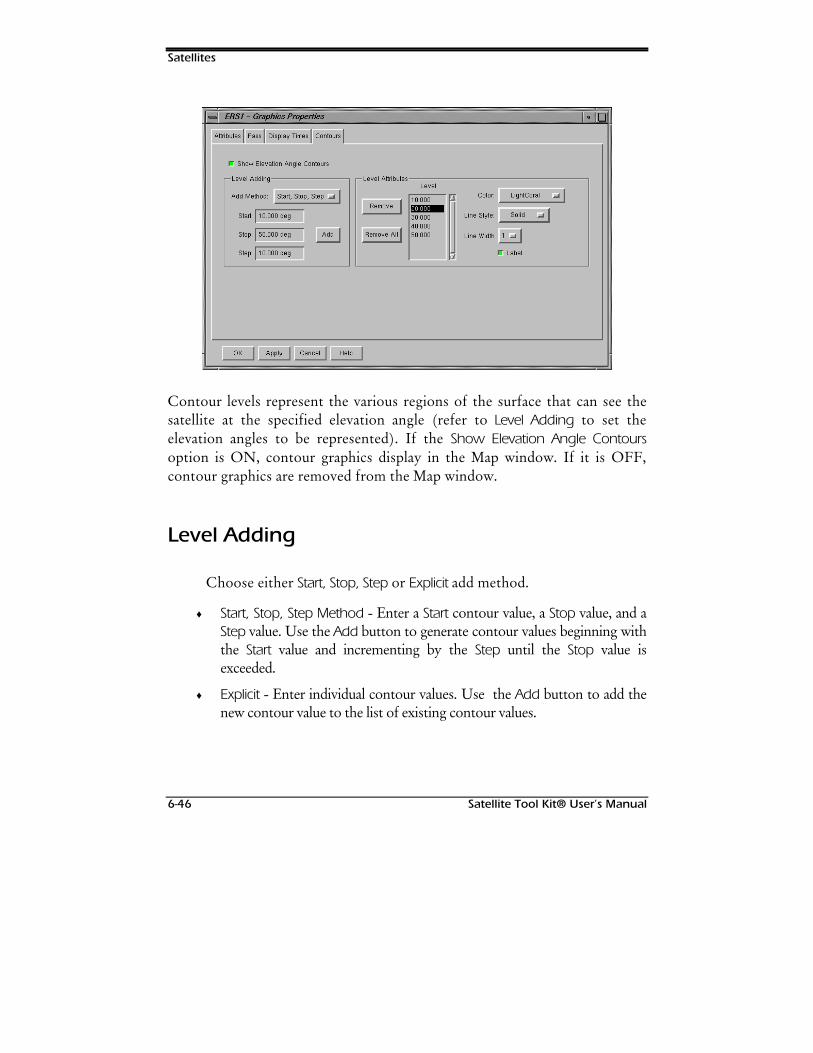
Satellites
6-46 Satellite Tool Kit® User’s Manual
Contour levels represent the various regions of the surface that can see thesatellite at the specified elevation angle (refer to Level Adding to set theelevation angles to be represented). If the Show Elevation Angle Contoursoption is ON, contour graphics display in the Map window. If it is OFF,contour graphics are removed from the Map window.
Level Adding
Choose either Start, Stop, Step or Explicit add method.
♦ Start, Stop, Step Method - Enter a Start contour value, a Stop value, and aStep value. Use the Add button to generate contour values beginning withthe Start value and incrementing by the Step until the Stop value isexceeded.
♦ Explicit - Enter individual contour values. Use the Add button to add thenew contour value to the list of existing contour values.
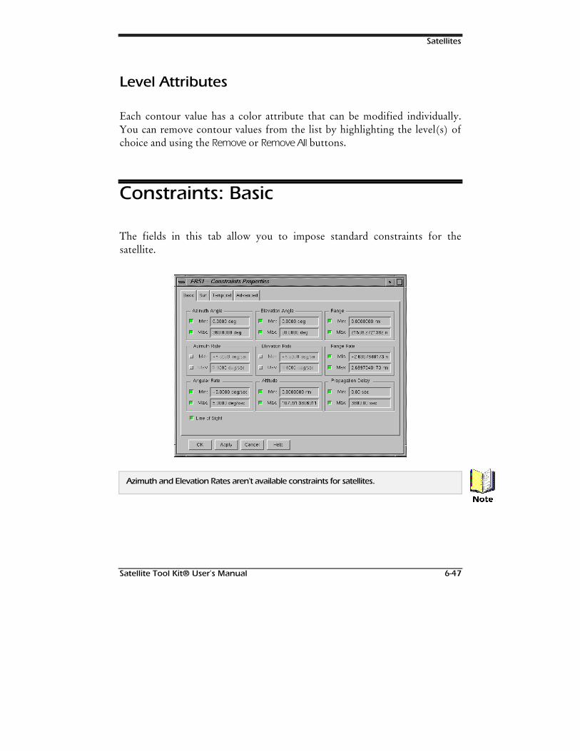
Satellites
Satellite Tool Kit® User’s Manual 6-47
Level Attributes
Each contour value has a color attribute that can be modified individually.You can remove contour values from the list by highlighting the level(s) ofchoice and using the Remove or Remove All buttons.
Constraints: Basic
The fields in this tab allow you to impose standard constraints for thesatellite.
Azimuth and Elevation Rates aren't available constraints for satellites.
1RWH
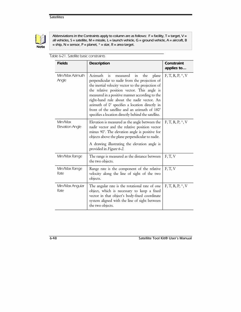
Satellites
6-48 Satellite Tool Kit® User’s Manual
Abbreviations in the Contraints apply to column are as follows: F = facility, T = target, V =all vehicles, S = satellite, M = missile, L = launch vehicle, G = ground vehicle, A = aircraft, B= ship, N = sensor, P = planet, * = star, R = area target.
Table 6--21. Satellite basic constraints
Fields Description Constraintapplies to…
Min/Max AzimuthAngle
Azimuth is measured in the planeperpendicular to nadir from the projection ofthe inertial velocity vector to the projection ofthe relative position vector. This angle ismeasured in a positive manner according to theright-hand rule about the nadir vector. Anazimuth of 0° specifies a location directly infront of the satellite and an azimuth of 180°specifies a location directly behind the satellite.
F, T, R, P, *, V
Min/MaxElevation Angle
Elevation is measured as the angle between thenadir vector and the relative position vectorminus 90°. The elevation angle is positive forobjects above the plane perpendicular to nadir.
A drawing illustrating the elevation angle isprovided in Figure 6-2.
F, T, R, P, *, V
Min/Max Range The range is measured as the distance betweenthe two objects.
F, T, V
Min/Max RangeRate
Range rate is the component of the relativevelocity along the line of sight of the twoobjects.
F, T, V
Min/Max AngularRate
The angular rate is the rotational rate of oneobject, which is necessary to keep a fixedvector in that object’s body-fixed coordinatesystem aligned with the line of sight betweenthe two objects.
F, T, R, P, *, V
1RWH
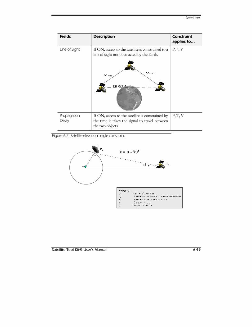
Satellites
Satellite Tool Kit® User’s Manual 6-49
Fields Description Constraintapplies to…
Line of Sight If ON, access to the satellite is constrained to aline of sight not obstructed by the Earth.
DFDFFFHHVVVV
DFDFFFHHVVVV
QR DFQR DFFFHHVVVV
P, *, V
PropagationDelay
If ON, access to the satellite is constrained bythe time it takes the signal to travel betweenthe two objects.
F, T, V
Figure 6-2. Satellite elevation angle constraint
ε α
α
3399
22
3366
//HJHJHHQGQG22 &HQWHU RI WKH (DUWK
3399
3RVLWLRQ RI WKH 9LHZHU RQ WKH (DUWKªV 6XUIDFH
3366
3RVLWLRQ RI WKH 6DWHOOLWH LQ 6SDFH
ε (OHYDWLRQ $QJOH
α $QJOH IURP 1DGLU
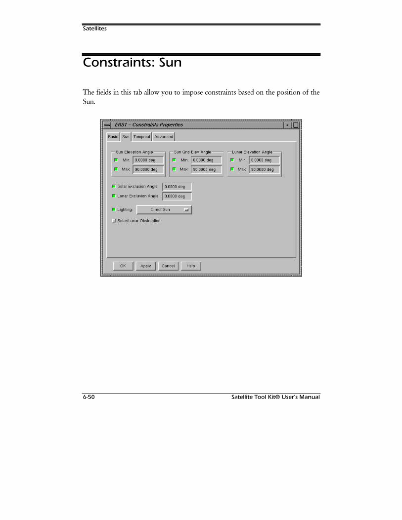
Satellites
6-50 Satellite Tool Kit® User’s Manual
Constraints: Sun
The fields in this tab allow you to impose constraints based on the position of theSun.
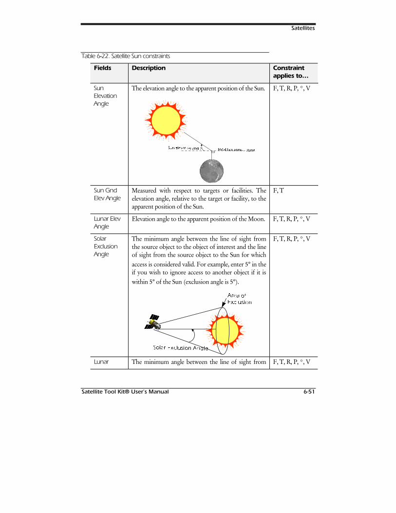
Satellites
Satellite Tool Kit® User’s Manual 6-51
Table 6--22. Satellite Sun constraints
Fields Description Constraintapplies to…
SunElevationAngle
The elevation angle to the apparent position of the Sun.
66XQXQ HOHOHHYDWLYDWLRRQQ DDQQJOJOHH OORRFFDDO KRUO KRULL]]RRQQWDWDO SO SODODQQHH
F, T, R, P, *, V
Sun GndElev Angle
Measured with respect to targets or facilities. Theelevation angle, relative to the target or facility, to theapparent position of the Sun.
F, T
Lunar ElevAngle
Elevation angle to the apparent position of the Moon. F, T, R, P, *, V
SolarExclusionAngle
The minimum angle between the line of sight fromthe source object to the object of interest and the lineof sight from the source object to the Sun for whichaccess is considered valid. For example, enter 5° in theif you wish to ignore access to another object if it iswithin 5° of the Sun (exclusion angle is 5°).
66RROODDUU ([([FFOXVOXVLLRRQQ $$QQJJOOHH
$$UUHHDD RRII(([[FFOOXXVLVLRRQQ
F, T, R, P, *, V
Lunar The minimum angle between the line of sight from F, T, R, P, *, V
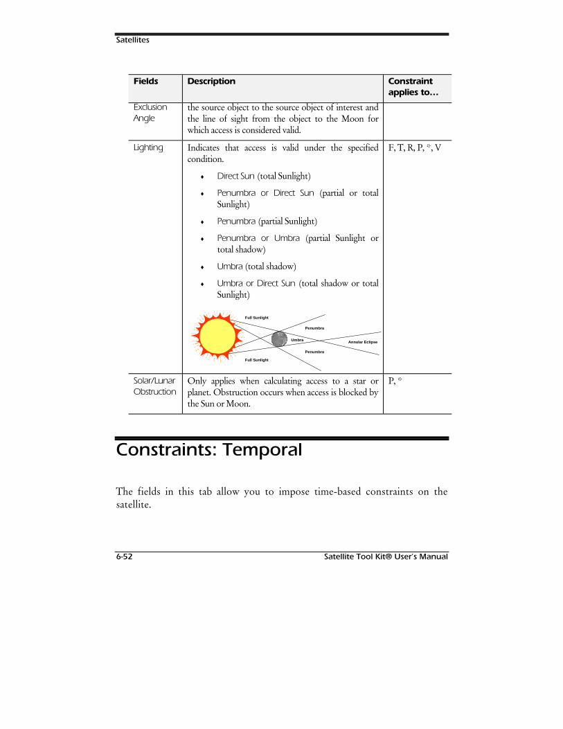
Satellites
6-52 Satellite Tool Kit® User’s Manual
Fields Description Constraintapplies to…
ExclusionAngle
the source object to the source object of interest andthe line of sight from the object to the Moon forwhich access is considered valid.
Lighting Indicates that access is valid under the specifiedcondition.
♦ Direct Sun (total Sunlight)
♦ Penumbra or Direct Sun (partial or totalSunlight)
♦ Penumbra (partial Sunlight)
♦ Penumbra or Umbra (partial Sunlight ortotal shadow)
♦ Umbra (total shadow)
♦ Umbra or Direct Sun (total shadow or totalSunlight)
Full Sunlight
Penumbra
Annular Eclipse
Full Sunlight
Penumbra
Umbra
F, T, R, P, *, V
Solar/LunarObstruction
Only applies when calculating access to a star orplanet. Obstruction occurs when access is blocked bythe Sun or Moon.
P, *
Constraints: Temporal
The fields in this tab allow you to impose time-based constraints on thesatellite.

Satellites
Satellite Tool Kit® User’s Manual 6-53
Table 6--23. Satellite temporal constraints
Fields Description Constraintapplies to…
Local Start and end local time constraints. The satellitelocal time is computed based upon the GMT ofinterest and the longitude of the satellite at thattime. For every degree of east longitude, fourminutes are added to GMT to yield the satellitelocal time.
F, T, R, P, *, V
GMT Start and end GMT time constraints. F, T, R, P, *, V
Local Apparent Start and end local apparent times. Using localapparent time, at noon the Sun is at the highestelevation. Also known as Local Satellite Time(LST).
F, T, R, P, *, V
Duration Minimum and maximum acceptable durationsfor computed accesses. If accesses whosedurations are outside these limits are computed,they are discarded from the resultant list.
F, T, R, P, *, V
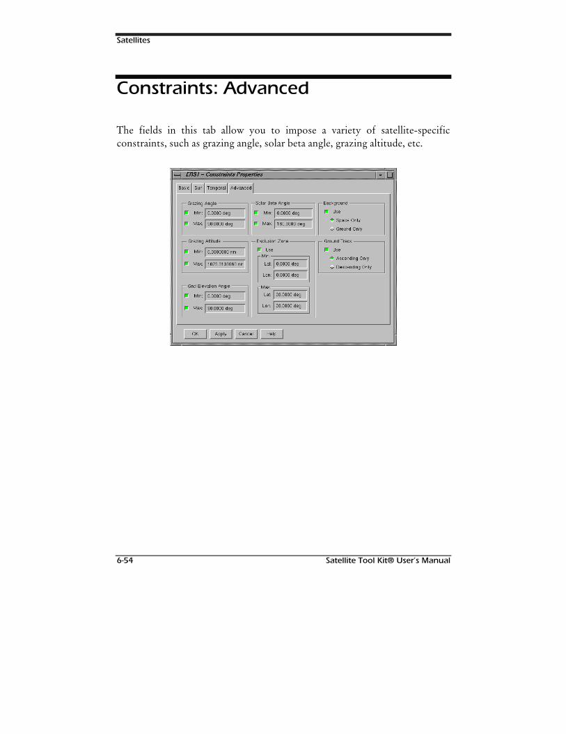
Satellites
6-54 Satellite Tool Kit® User’s Manual
Constraints: Advanced
The fields in this tab allow you to impose a variety of satellite-specificconstraints, such as grazing angle, solar beta angle, grazing altitude, etc.
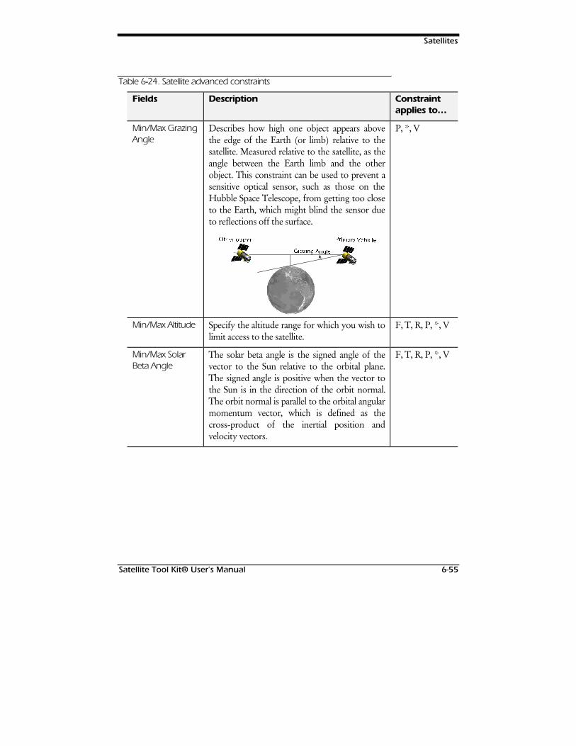
Satellites
Satellite Tool Kit® User’s Manual 6-55
Table 6--24. Satellite advanced constraints
Fields Description Constraintapplies to…
Min/Max GrazingAngle
Describes how high one object appears abovethe edge of the Earth (or limb) relative to thesatellite. Measured relative to the satellite, as theangle between the Earth limb and the otherobject. This constraint can be used to prevent asensitive optical sensor, such as those on theHubble Space Telescope, from getting too closeto the Earth, which might blind the sensor dueto reflections off the surface.
*U*UD]LD]LQQJJ $$QJQJOHOH
22WWKHKHUU REREMMHHFFWW 33UULPLPDDU\U\ 99HKHKLLFFOOHH
P, *, V
Min/Max Altitude Specify the altitude range for which you wish tolimit access to the satellite.
F, T, R, P, *, V
Min/Max SolarBeta Angle
The solar beta angle is the signed angle of thevector to the Sun relative to the orbital plane.The signed angle is positive when the vector tothe Sun is in the direction of the orbit normal.The orbit normal is parallel to the orbital angularmomentum vector, which is defined as thecross-product of the inertial position andvelocity vectors.
F, T, R, P, *, V
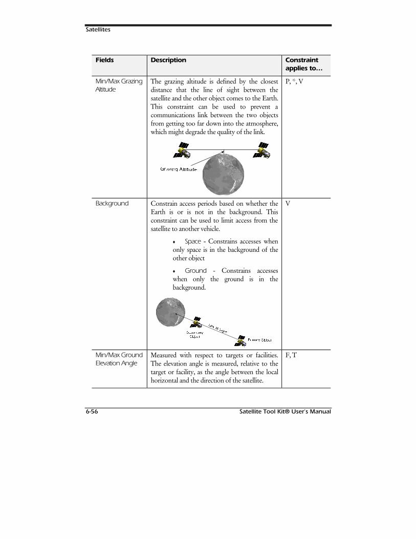
Satellites
6-56 Satellite Tool Kit® User’s Manual
Fields Description Constraintapplies to…
Min/Max GrazingAltitude
The grazing altitude is defined by the closestdistance that the line of sight between thesatellite and the other object comes to the Earth.This constraint can be used to prevent acommunications link between the two objectsfrom getting too far down into the atmosphere,which might degrade the quality of the link.
**UUD]LD]LQQJJ $$OOWLWWLWXGHXGH
P, *, V
Background Constrain access periods based on whether theEarth is or is not in the background. Thisconstraint can be used to limit access from thesatellite to another vehicle.
♦ Space - Constrains accesses whenonly space is in the background of theother object
♦ Ground - Constrains accesseswhen only the ground is in thebackground.
33UULPLPDUDU\\ 22EMHEMHFFWW
6HF6HFRRQGQGDDUU\\22EMHEMHFFWW
/LQ/LQH RH RII 66LLJJKWKW
V
Min/Max GroundElevation Angle
Measured with respect to targets or facilities.The elevation angle is measured, relative to thetarget or facility, as the angle between the localhorizontal and the direction of the satellite.
F, T
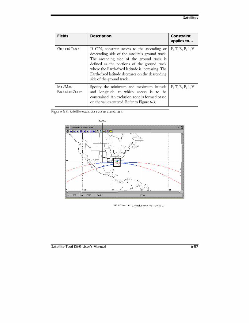
Satellites
Satellite Tool Kit® User’s Manual 6-57
Fields Description Constraintapplies to…
Ground Track If ON, constrain access to the ascending ordescending side of the satellite’s ground track.The ascending side of the ground track isdefined as the portions of the ground trackwhere the Earth-fixed latitude is increasing. TheEarth-fixed latitude decreases on the descendingside of the ground track.
F, T, R, P, *, V
Min/MaxExclusion Zone
Specify the minimum and maximum latitudeand longitude at which access is to beconstrained. An exclusion zone is formed basedon the values entered. Refer to Figure 6-3.
F, T, R, P, *, V
Figure 6-3. Satellite exclusion zone constraint
DFDFFFHVVHVV
QQR DR DFFFFHVVHVV GGXXHH WR HWR H[[FFOOXXVLRVLRQQ ]]RRQHQH FFRRQVWQVWUUDDLQWLQW

Satellites
6-58 Satellite Tool Kit® User’s Manual
127(6

Satellite Tool Kit® User’s Manual 7-1
7SHIPS, AIRCRAFT &
GROUNDVEHICLES
Overview
This chapter describes nonorbiting vehicles, and provides instructions for settingthe basic and graphics properties as well as the access constraints of aircraft, groundvehicles and ships. It also provides instructions for manipulating aircraft, groundvehicles and ships to obtain the information you need for analysis and problem-solving.
Chapter Contents
Route ...........................................................................................................7-2
Attitude ........................................................................................................7-4
Ships, Aircraft & Ground Vehicles
7-2 Satellite Tool Kit® User’s Manual
External Attitude File ...............................................................................7-6
Graphics Properties: Attributes .....................................................................7-6
Graphics Properties: Display Times...............................................................7-8
Aircraft, Ground Vehicle & Ship Constraints.................................................7-9
Constraints: Advanced - Aircraft Only.........................................................7-10
Route
To define a route for your ship, aircraft or ground vehicle, open the BasicProperties window for the object. In the Route tab, you can define thetrajectory which the object follows. At the top of this panel, the Start Timeand Stop Time fields specify the temporal boundaries of your aircraft, groundvehicles and ships. The default values for Start Time and Stop Time are yourscenario start and stop times. The Step Size field specifies the intervalbetween calculated ephemeris output points. The default value is 60 seconds.
You can choose to use the Great Arc Propagator or an external file containingroute information. The Great Arc Propagator defines aircraft, ground vehiclesand ships that follow a point-by-point path over the surface of the Earth at agiven altitude. The waypoints specified represent a particular latitude,longitude, altitude and speed along the path. Great Arc paths, each of whichlies in a plane that contains the center of the Earth, are used to connect thewaypoints.
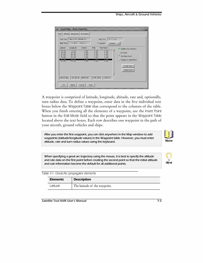
Ships, Aircraft & Ground Vehicles
Satellite Tool Kit® User’s Manual 7-3
A waypoint is comprised of latitude, longitude, altitude, rate and, optionally,turn radius data. To define a waypoint, enter data in the five individual textboxes below the Waypoint Table that correspond to the columns of the table.When you finish entering all the elements of a waypoint, use the Insert Pointbutton in the Edit Mode field so that the point appears in the Waypoint Tablelocated above the text boxes. Each row describes one waypoint in the path ofyour aircraft, ground vehicles and ships.
After you enter the first waypoint, you can click anywhere in the Map window to addwaypoints (latitude/longitude values) in the Waypoint table. However, you must enteraltitude, rate and turn radius values using the keyboard.
When specifying a great arc trajectory using the mouse, it is best to specify the altitudeand rate data on the first point before creating the second point so that the initial altitudeand rule information become the default for all additional points.
Table 7--1. Great Arc propagator elements
Elements Description
Latitude The latitude of the waypoint.
1RWH
+LQW
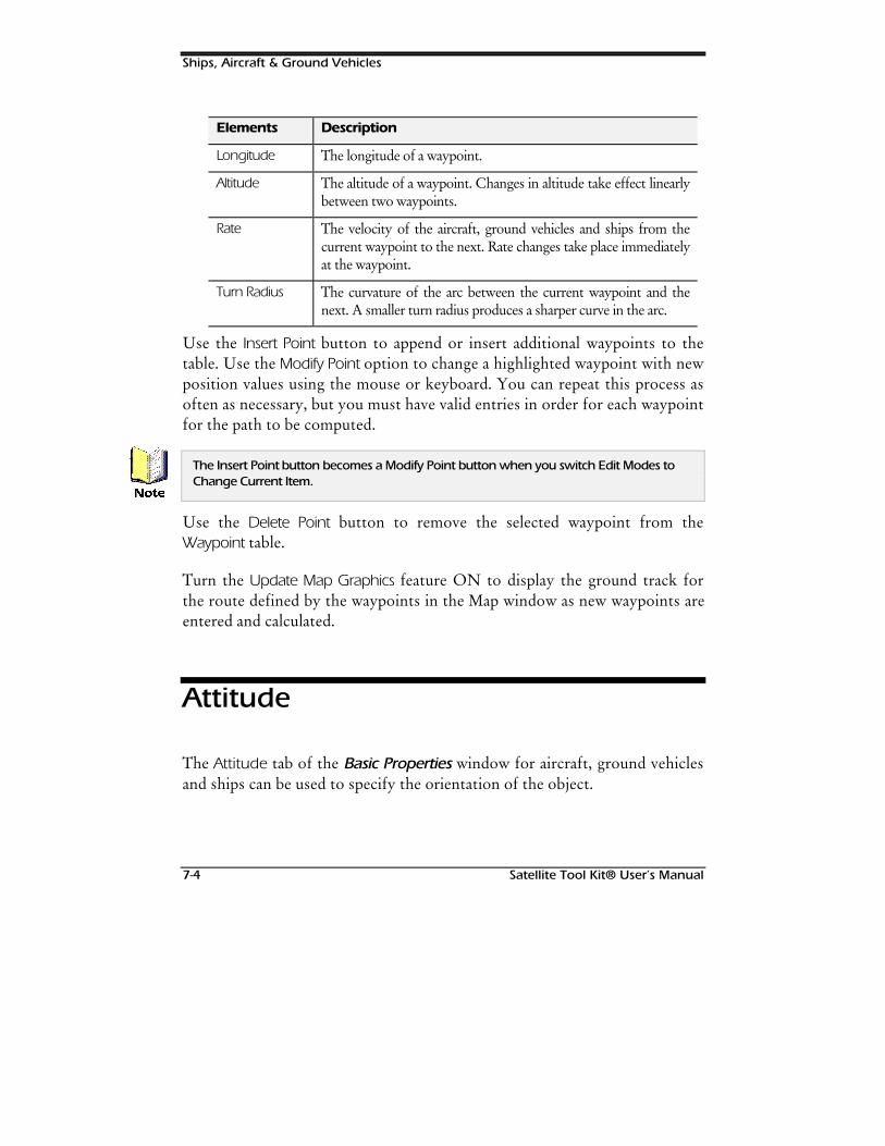
Ships, Aircraft & Ground Vehicles
7-4 Satellite Tool Kit® User’s Manual
Elements Description
Longitude The longitude of a waypoint.
Altitude The altitude of a waypoint. Changes in altitude take effect linearlybetween two waypoints.
Rate The velocity of the aircraft, ground vehicles and ships from thecurrent waypoint to the next. Rate changes take place immediatelyat the waypoint.
Turn Radius The curvature of the arc between the current waypoint and thenext. A smaller turn radius produces a sharper curve in the arc.
Use the Insert Point button to append or insert additional waypoints to thetable. Use the Modify Point option to change a highlighted waypoint with newposition values using the mouse or keyboard. You can repeat this process asoften as necessary, but you must have valid entries in order for each waypointfor the path to be computed.
The Insert Point button becomes a Modify Point button when you switch Edit Modes toChange Current Item.
Use the Delete Point button to remove the selected waypoint from theWaypoint table.
Turn the Update Map Graphics feature ON to display the ground track forthe route defined by the waypoints in the Map window as new waypoints areentered and calculated.
Attitude
The Attitude tab of the Basic Properties window for aircraft, ground vehiclesand ships can be used to specify the orientation of the object.
1RWH
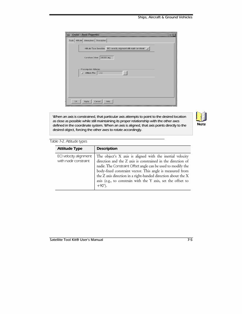
Ships, Aircraft & Ground Vehicles
Satellite Tool Kit® User’s Manual 7-5
When an axis is constrained, that particular axis attempts to point to the desired locationas close as possible while still maintaining its proper relationship with the other axesdefined in the coordinate system. When an axis is aligned, that axis points directly to thedesired object, forcing the other axes to rotate accordingly.
Table 7--2. Attitude types
Attitude Type Description
ECI velocity alignmentwith nadir constraint
The object’s X axis is aligned with the inertial velocitydirection and the Z axis is constrained in the direction ofnadir. The Constraint Offset angle can be used to modify thebody-fixed constraint vector. This angle is measured fromthe Z axis direction in a right-handed direction about the Xaxis (e.g., to constrain with the Y axis, set the offset to+90°).
1RWH
Ships, Aircraft & Ground Vehicles
7-6 Satellite Tool Kit® User’s Manual
Attitude Type Description
ECF velocityalignment with radialconstraint
The object’s X axis is aligned with the Earth fixed velocitydirection and the Z axis is constrained in the directionopposite to nadir. The Constraint Offset angle can be used tomodify the body-fixed constraint vector. This angle ismeasured from the Z axis direction in a right-handeddirection about the X axis (e.g.., to constrain with the Y axisset the offset to +90°). This attitude profile is commonlyused for aircraft and surface-based vehicles.
The ECF velocity alignment with radial constraint profile is most appropriate for surfacevehicles and aircraft.
Small animation time steps may be needed to properly visualize satellites with spinningattitude profiles.
External Attitude File
You can use external attitude data by entering an attitude file containingquaternions. Turn the Attitude File option ON and specify the attitude file touse. If ON, the file overrides the default attitude profile during the time spanof the quaternions contained in the file. The external attitude file format isdescried in Appendix C of this manual.
Graphics Properties: Attributes
The Attributes tab allows you to specify several aspects used to represent theaircraft, ground vehicle or ship in the Map window.
+LQW

Ships, Aircraft & Ground Vehicles
Satellite Tool Kit® User’s Manual 7-7
Table 7--3. Options in the Attributes tab
Field Description
Color The color of the object’s marker and tracks in the Map window.
Line Style The type of line used to represent the object’s route. Choices areLong Dash, Solid, Dashed, Dotted, or Dot Dash.
Line Width The width of the object’s route, in pixels, in the Map window.
Marker Style The type of marker used to represent the object’s current position.Choices are Square, Point, Plus Sign, Star, Circle, or an X.
You can also add a custom marker by creating a pixmap file with a.marker extension and saving it to your <Home>/stkData/Pixmaps directory. pixmaps can be any size. Once created, custommarkers are available in the Marker Style list.
Inherit Settings If ON, the object’s label and trajectory are displayed in accordancewith the scenario’s graphics attributes, set through the Attributestab of the scenario’s Graphics Properties window. If OFF, theoptions here override those set at the scenario level.
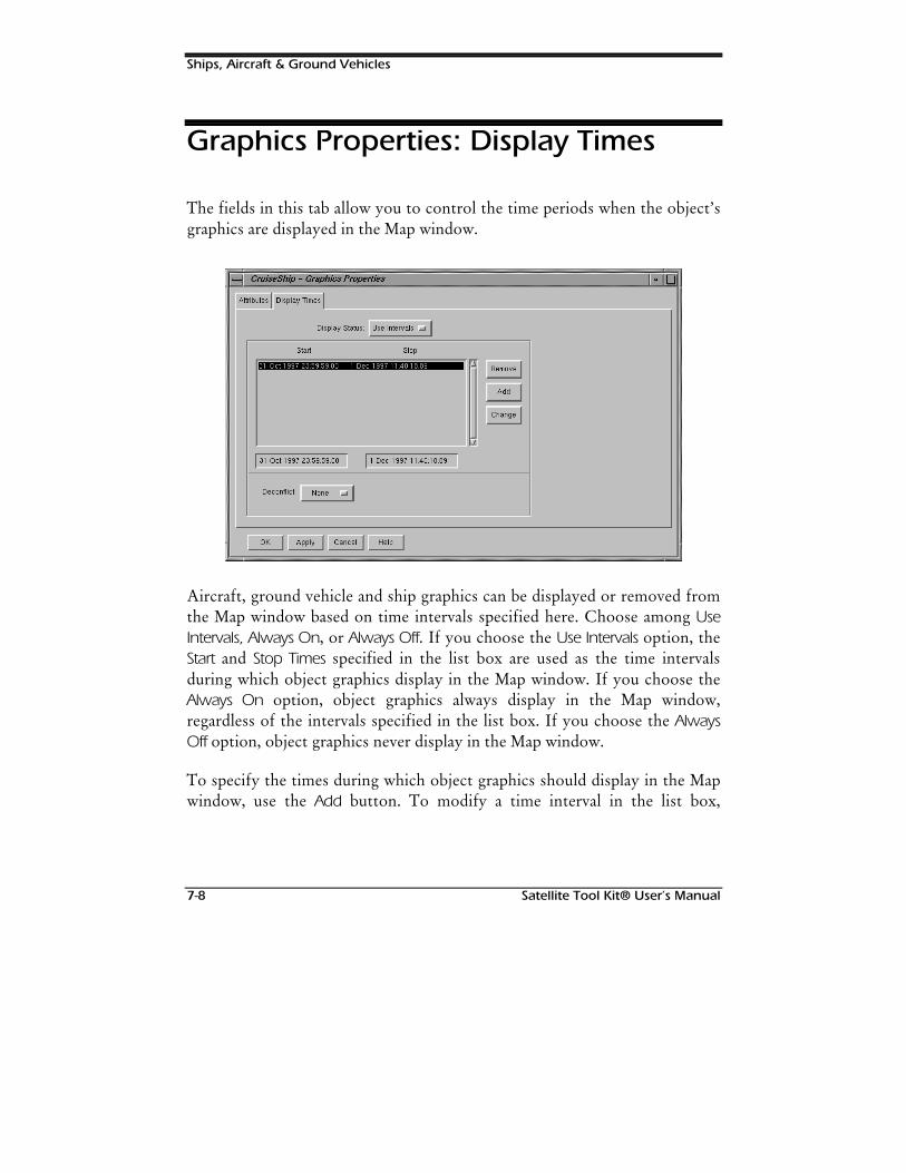
Ships, Aircraft & Ground Vehicles
7-8 Satellite Tool Kit® User’s Manual
Graphics Properties: Display Times
The fields in this tab allow you to control the time periods when the object’sgraphics are displayed in the Map window.
Aircraft, ground vehicle and ship graphics can be displayed or removed fromthe Map window based on time intervals specified here. Choose among UseIntervals, Always On, or Always Off. If you choose the Use Intervals option, theStart and Stop Times specified in the list box are used as the time intervalsduring which object graphics display in the Map window. If you choose theAlways On option, object graphics always display in the Map window,regardless of the intervals specified in the list box. If you choose the AlwaysOff option, object graphics never display in the Map window.
To specify the times during which object graphics should display in the Mapwindow, use the Add button. To modify a time interval in the list box,
Ships, Aircraft & Ground Vehicles
Satellite Tool Kit® User’s Manual 7-9
highlight the time period of interest and use the Change button. To remove atime period, use the Remove button.
You can also choose whether the time intervals should be “deconflicted,” ormodified so that time periods don’t overlap. If the Deconflict option is set toAutomatic, STK automatically modifies all time intervals during which anoverlap occurs so that the intervals are further segmented to avoid overlap. Ifthe option is set to None, no changes are made to time interval overlaps. Ifthe option is set to Manual, when an overlap occurs in the time interval list,an Acknowledge window appears when you click the OK or Apply button toalert you to the fact that overlap(s) exists. It is then your decision whether toset the Deconflict field to Automatic so that overlap(s) are fixed, change thetime intervals yourself by modifying the appropriate entries in the list box, orignore the message and continue.
The time intervals only apply to the graphical display of the object—they don’t affectaccess computations.
Aircraft, Ground Vehicle & ShipConstraints
The basic, Sun and temporal constraints that can be imposed on an aircraft,ground vehicle or ship in STK are the same as those that can be applied tosatellites. Please refer to Chapter 6, Satellites, for a detailed summary of theconstraints available for all vehicles. There are no advanced constraints forground vehicles and ships.
1RWH
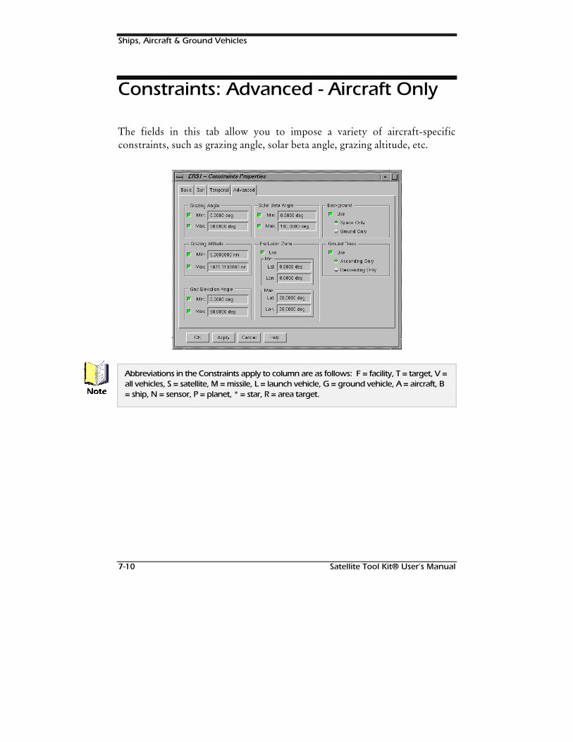
Ships, Aircraft & Ground Vehicles
7-10 Satellite Tool Kit® User’s Manual
Constraints: Advanced - Aircraft Only
The fields in this tab allow you to impose a variety of aircraft-specificconstraints, such as grazing angle, solar beta angle, grazing altitude, etc.
Abbreviations in the Constraints apply to column are as follows: F = facility, T = target, V =all vehicles, S = satellite, M = missile, L = launch vehicle, G = ground vehicle, A = aircraft, B= ship, N = sensor, P = planet, * = star, R = area target.1RWH
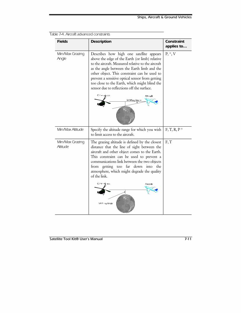
Ships, Aircraft & Ground Vehicles
Satellite Tool Kit® User’s Manual 7-11
Table 7--4. Aircraft advanced constraints
Fields Description Constraintapplies to…
Min/Max GrazingAngle
Describes how high one satellite appearsabove the edge of the Earth (or limb) relativeto the aircraft. Measured relative to the aircraftas the angle between the Earth limb and theother object. This constraint can be used toprevent a sensitive optical sensor from gettingtoo close to the Earth, which might blind thesensor due to reflections off the surface.
**UUD]D]LLQJQJ $$QQJJOHOH
2WK2WKHHU RU REEMMHFHFWW $$LLUUFFUUDIDIWW
P, *, V
Min/Max Altitude Specify the altitude range for which you wishto limit access to the aircraft.
F, T, R, P *
Min/Max GrazingAltitude
The grazing altitude is defined by the closestdistance that the line of sight between theaircraft and other object comes to the Earth.This constraint can be used to prevent acommunications link between the two objectsfrom getting too far down into theatmosphere, which might degrade the qualityof the link.
**UUD]D]LLQJQJ $$QQJJOHOH
2WK2WKHHU RU REEMMHFHFWW $$LLUUFFUUDIDIWW
F, T
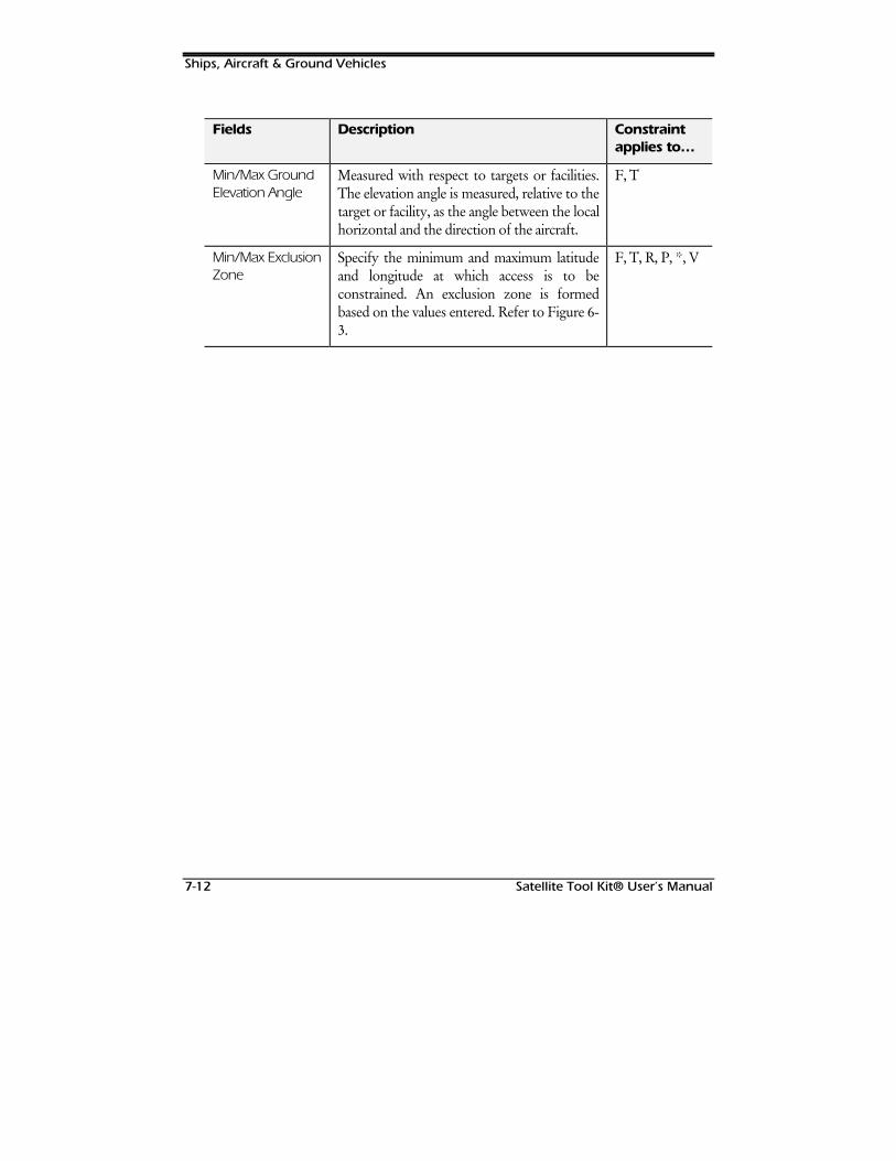
Ships, Aircraft & Ground Vehicles
7-12 Satellite Tool Kit® User’s Manual
Fields Description Constraintapplies to…
Min/Max GroundElevation Angle
Measured with respect to targets or facilities.The elevation angle is measured, relative to thetarget or facility, as the angle between the localhorizontal and the direction of the aircraft.
F, T
Min/Max ExclusionZone
Specify the minimum and maximum latitudeand longitude at which access is to beconstrained. An exclusion zone is formedbased on the values entered. Refer to Figure 6-3.
F, T, R, P, *, V
Satellite Tool Kit® User’s Manual 8-1
8LAUNCH
VEHICLES &MISSILES
Overview
This chapter describes nonorbiting vehicles, and provides instructions for settingthe basic and graphics properties as well as the access constraints of vehicles. It alsoprovides instructions for manipulating vehicles to obtain the information you needfor analysis and problem-solving.
Chapter Contents
Basic Properties: Trajectory...........................................................................8-2
Simple Ascent Propagator (Launch Vehicles)..........................................8-2
Ballistic Propagator (Missiles) ...................................................................8-3
Launch Vehicles & Missiles
8-2 Satellite Tool Kit® User’s Manual
External Propagator ................................................................................8-5
Basic Properties: Attitude..............................................................................8-6
External Attitude File ...............................................................................8-7
Graphics Properties: Attributes .....................................................................8-7
Graphics Properties: Display Times...............................................................8-9
Graphics Properties: Contours ...................................................................8-10
Level Adding.........................................................................................8-11
Level Attributes......................................................................................8-12
Launch Vehicle & Missile Constraints..........................................................8-12
Basic Properties: Trajectory
To define a trajectory for your launch vehicle or missile, open the BasicProperties window for the object. In the Trajectory tab, you can define thepath which the object follows. At the top of this panel, the Start Time and StopTime fields specify the temporal boundaries of the object. The default valuesfor Start Time and Stop Time are your scenario start and stop times. The StepSize field specifies the interval between calculated ephemeris output points.The default value is 60 seconds.
Launch vehicles and missiles each have their own special propagator inaddition to the option of using external files to define their trajectories.
Simple Ascent Propagator (LaunchVehicles)
The simple ascent propagator creates an ascent trajectory based on the launchand insertion parameters supplied by the user. The trajectory is a simple

Launch Vehicles & Missiles
Satellite Tool Kit® User’s Manual 8-3
curve rising vertically from the launch pad that smoothly turns over to insertwith a zero flight path angle at the insertion point with the user-specifiedvelocity.
Table 8--1. Simple Ascent propagator elements
Elements Description
Launch Location(first 3 fields)
Select one of the following two combinations:
♦ Launch Geodetic Latitude, Launch Longitude andLaunch Altitude
♦ Launch Geocentric Latitude, Launch Longitude,Launch Radius
STK links these elements in such a way that switching one ofthem from geodetic to geocentric (or vice versa) changes theother correspondingly. Longitude is not differentiated alonggeodetic/geocentric lines.
Burnout Velocity(4th field)
Specify the burnout velocity in the units selected at the scenariolevel.
Burnout Location(last 3 fields)
These elements are linked and only two combinations are valid.
♦ Impact Latitude-Geodetic / Impact Longitude /Impact Altitude.
♦ Impact Latitude-Geocentric / Impact Longitude /Impact Radius
Impact Latitude can be geodetic or geocentric, but need notagree in this respect with Launch Latitude.
Ballistic Propagator (Missiles)
The Ballistic Propagator defines vehicles following an elliptical path that beginsand ends at the Earth’s surface. The shape of the trajectory can be furtherrefined by specifying a fixed flight time, initial velocity or altitude.
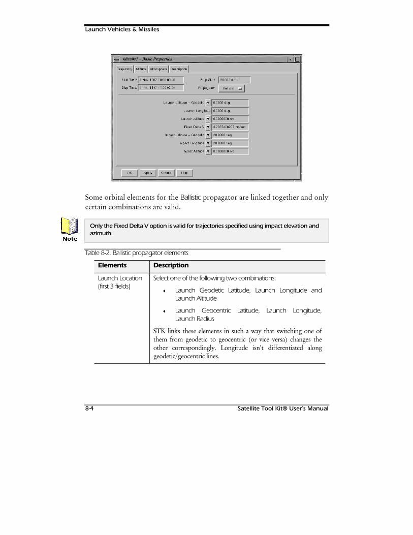
Launch Vehicles & Missiles
8-4 Satellite Tool Kit® User’s Manual
Some orbital elements for the Ballistic propagator are linked together and onlycertain combinations are valid.
Only the Fixed Delta V option is valid for trajectories specified using impact elevation andazimuth.
Table 8--2. Ballistic propagator elements
Elements Description
Launch Location(first 3 fields)
Select one of the following two combinations:
♦ Launch Geodetic Latitude, Launch Longitude andLaunch Altitude
♦ Launch Geocentric Latitude, Launch Longitude,Launch Radius
STK links these elements in such a way that switching one ofthem from geodetic to geocentric (or vice versa) changes theother correspondingly. Longitude isn’t differentiated alonggeodetic/geocentric lines.
1RWH
Launch Vehicles & Missiles
Satellite Tool Kit® User’s Manual 8-5
Elements Description
Flight Parameters(4th field)
When you enter a value for one of these elements, the systemautomatically calculates the other values. Flight parameters canbe specified in one of three ways:
♦ Fixed Delta V - The instantaneous thrust to be appliedto the vehicle being launched. If you enter 0, theminimum Delta V is computed for launch and impactlocations.
♦ Fixed Apogee Alt - The vehicle’s maximum altitude.
♦ Fixed Time of Flight - The duration of the vehicle’sflight.
Impact Location(last 3 fields)
These elements are linked and only three combinations are valid.
♦ Impact Latitude-Geodetic / Impact Longitude / ImpactAltitude.
♦ Impact Latitude-Geocentric / Impact Longitude /Impact Radius
♦ Impact Elevation / Impact Azimuth.
Impact Latitude can be geodetic or geocentric, but need notagree in this respect with Launch Latitude.
You can also enter launch points using the mouse in the Map window.
External Propagator
This propagator allows you to read the ephemeris for a launch vehicle ormissile from a file. Turn ON the External Ephemeris File field, then specify thefile you wish to use.
1RWH+LQW
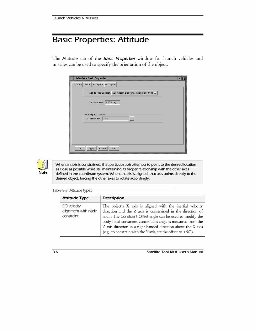
Launch Vehicles & Missiles
8-6 Satellite Tool Kit® User’s Manual
Basic Properties: Attitude
The Attitude tab of the Basic Properties window for launch vehicles andmissiles can be used to specify the orientation of the object.
When an axis is constrained, that particular axis attempts to point to the desired locationas close as possible while still maintaining its proper relationship with the other axesdefined in the coordinate system. When an axis is aligned, that axis points directly to thedesired object, forcing the other axes to rotate accordingly.
Table 8--3. Attitude types
Attitude Type Description
ECI velocityalignment with nadirconstraint
The object’s X axis is aligned with the inertial velocitydirection and the Z axis is constrained in the direction ofnadir. The Constraint Offset angle can be used to modify thebody-fixed constraint vector. This angle is measured from theZ axis direction in a right-handed direction about the X axis(e.g., to constrain with the Y axis, set the offset to +90°).
1RWH
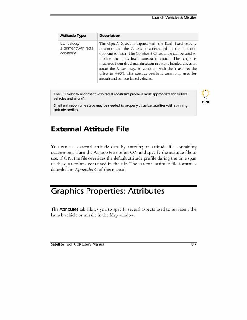
Launch Vehicles & Missiles
Satellite Tool Kit® User’s Manual 8-7
Attitude Type Description
ECF velocityalignment with radialconstraint
The object’s X axis is aligned with the Earth fixed velocitydirection and the Z axis is constrained in the directionopposite to nadir. The Constraint Offset angle can be used tomodify the body-fixed constraint vector. This angle ismeasured from the Z axis direction in a right-handed directionabout the X axis (e.g.., to constrain with the Y axis set theoffset to +90°). This attitude profile is commonly used foraircraft and surface-based vehicles.
The ECF velocity alignment with radial constraint profile is most appropriate for surfacevehicles and aircraft.
Small animation time steps may be needed to properly visualize satellites with spinningattitude profiles.
External Attitude File
You can use external attitude data by entering an attitude file containingquaternions. Turn the Attitude File option ON and specify the attitude file touse. If ON, the file overrides the default attitude profile during the time spanof the quaternions contained in the file. The external attitude file format isdescribed in Appendix C of this manual.
Graphics Properties: Attributes
The Attributes tab allows you to specify several aspects used to represent thelaunch vehicle or missile in the Map window.
+LQW
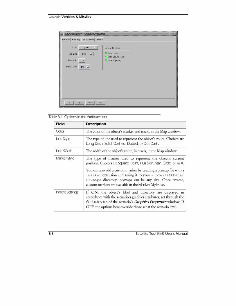
Launch Vehicles & Missiles
8-8 Satellite Tool Kit® User’s Manual
Table 8--4. Options in the Attributes tab
Field Description
Color The color of the object’s marker and tracks in the Map window.
Line Style The type of line used to represent the object’s route. Choices areLong Dash, Solid, Dashed, Dotted, or Dot Dash.
Line Width The width of the object’s route, in pixels, in the Map window.
Marker Style The type of marker used to represent the object’s currentposition. Choices are Square, Point, Plus Sign, Star, Circle, or an X.
You can also add a custom marker by creating a pixmap file with a.marker extension and saving it to your <Home>/stkData/Pixmaps directory. pixmaps can be any size. Once created,custom markers are available in the Marker Style list.
Inherit Settings If ON, the object’s label and trajectory are displayed inaccordance with the scenario’s graphics attributes, set through theAttributes tab of the scenario’s Graphics Properties window. IfOFF, the options here override those set at the scenario level.
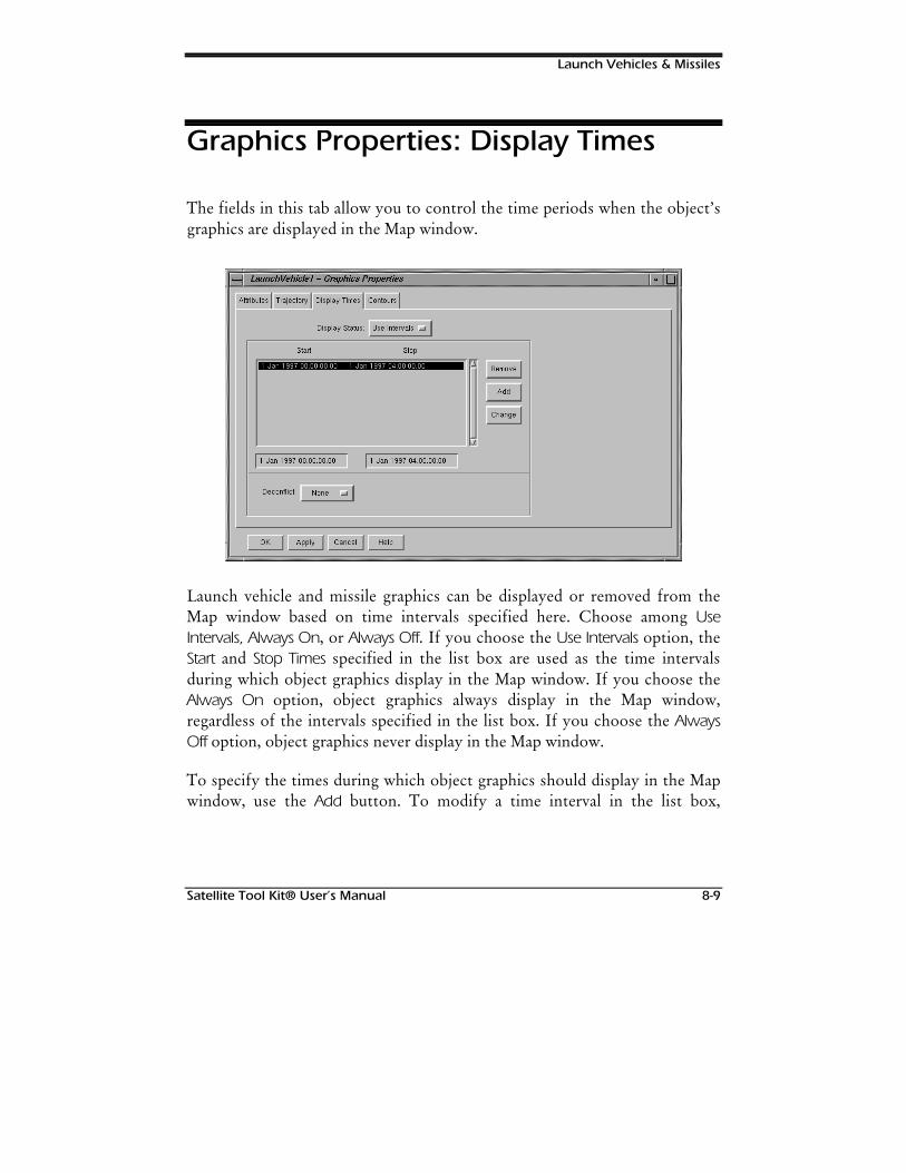
Launch Vehicles & Missiles
Satellite Tool Kit® User’s Manual 8-9
Graphics Properties: Display Times
The fields in this tab allow you to control the time periods when the object’sgraphics are displayed in the Map window.
Launch vehicle and missile graphics can be displayed or removed from theMap window based on time intervals specified here. Choose among UseIntervals, Always On, or Always Off. If you choose the Use Intervals option, theStart and Stop Times specified in the list box are used as the time intervalsduring which object graphics display in the Map window. If you choose theAlways On option, object graphics always display in the Map window,regardless of the intervals specified in the list box. If you choose the AlwaysOff option, object graphics never display in the Map window.
To specify the times during which object graphics should display in the Mapwindow, use the Add button. To modify a time interval in the list box,
Launch Vehicles & Missiles
8-10 Satellite Tool Kit® User’s Manual
highlight the time period of interest and use the Change button. To remove atime period, use the Remove button.
You can also choose whether the time intervals should be “deconflicted,” ormodified so that time periods don’t overlap. If the Deconflict option is set toAutomatic, STK automatically modifies all time intervals during which anoverlap occurs so that the intervals are further segmented to avoid overlap. Ifthe option is set to None, no changes are made to time interval overlaps. Ifthe option is set to Manual, when an overlap occurs in the time interval list,an Acknowledge window appears when you click the OK or Apply button toalert you to the fact that overlap(s) exists. It is then your decision whether toset the Deconflict field to Automatic so that overlap(s) are fixed, change thetime intervals yourself by modifying the appropriate entries in the list box, orignore the message and continue.
The time intervals only apply to the graphical display of the object—they don’t affectaccess computations.
Graphics Properties: Contours
The fields in this tab allow you to control the display of launch vehicle andmissile contours in the Map window.
1RWH
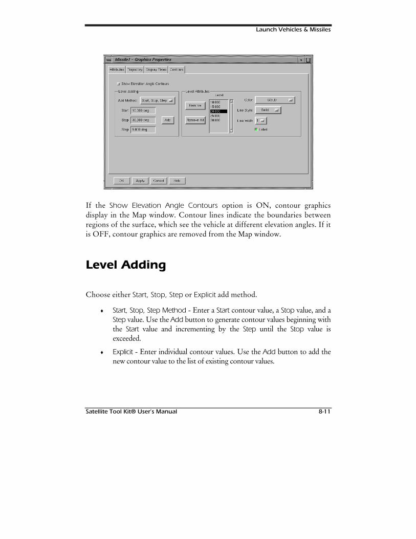
Launch Vehicles & Missiles
Satellite Tool Kit® User’s Manual 8-11
If the Show Elevation Angle Contours option is ON, contour graphicsdisplay in the Map window. Contour lines indicate the boundaries betweenregions of the surface, which see the vehicle at different elevation angles. If itis OFF, contour graphics are removed from the Map window.
Level Adding
Choose either Start, Stop, Step or Explicit add method.
♦ Start, Stop, Step Method - Enter a Start contour value, a Stop value, and aStep value. Use the Add button to generate contour values beginning withthe Start value and incrementing by the Step until the Stop value isexceeded.
♦ Explicit - Enter individual contour values. Use the Add button to add thenew contour value to the list of existing contour values.

Launch Vehicles & Missiles
8-12 Satellite Tool Kit® User’s Manual
Level Attributes
Each contour value has a color attribute that can be modified individually.You can remove contour values from the list by highlighting the level(s) ofchoice and using the Remove or Remove All buttons.
STK maintains separate contour lists for each contour so that you can definedifferent values for each type and switch back and forth as desired.
Launch Vehicle & Missile Constraints
The constraints that can be imposed on a launch vehicle or missile in STK arethe same as those that can be applied to satellites. Please refer to Chapter 6,Satellites, for a detailed summary of the constraints available for all vehicles.
Satellite Tool Kit® User’s Manual 9-1
9FACILITIES &
TARGETS
Overview
Facilities are defined as nonmobile points on the Earth’s surface. Typically,facilities mark the position of ground stations, launch sites, tracking stations,etc. Targets are also objects that mark locations on the Earth’s surface; assuch they can be used to represent points of interest for sensor coverage,locations of cities, etc. Although facilities and targets are managed separatelyin STK, they are functionally identical and are addressed concurrently in thischapter. The objects are separated within STK to help in your analysis tasks.
Chapter Contents
Basic Properties: Position ..............................................................................9-2
Geodetic Position....................................................................................9-3
Spherical Position....................................................................................9-4
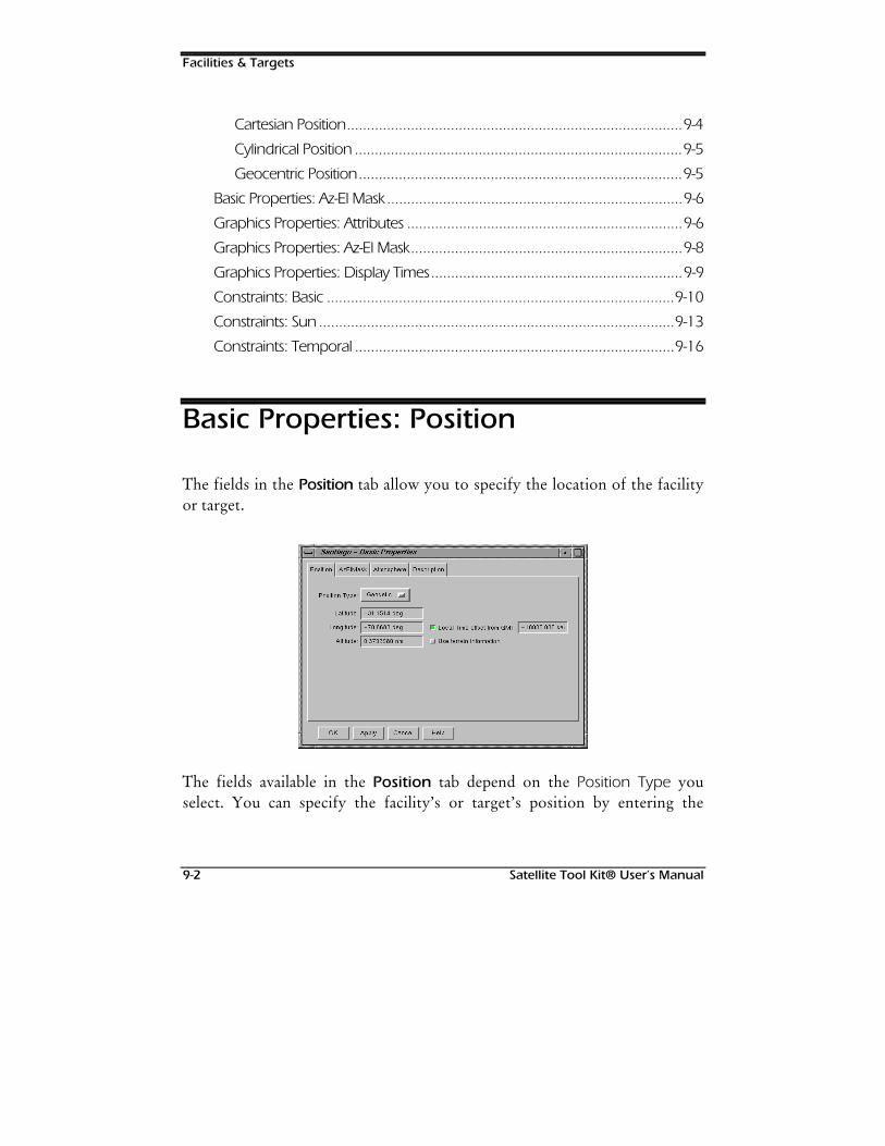
Facilities & Targets
9-2 Satellite Tool Kit® User’s Manual
Cartesian Position....................................................................................9-4
Cylindrical Position ..................................................................................9-5
Geocentric Position.................................................................................9-5
Basic Properties: Az-El Mask..........................................................................9-6
Graphics Properties: Attributes .....................................................................9-6
Graphics Properties: Az-El Mask....................................................................9-8
Graphics Properties: Display Times...............................................................9-9
Constraints: Basic .......................................................................................9-10
Constraints: Sun.........................................................................................9-13
Constraints: Temporal ................................................................................9-16
Basic Properties: Position
The fields in the Position tab allow you to specify the location of the facilityor target.
The fields available in the Position tab depend on the Position Type youselect. You can specify the facility’s or target’s position by entering the

Facilities & Targets
Satellite Tool Kit® User’s Manual 9-3
appropriate values in the fields of this tab or by clicking on the point atwhich you wish to locate the object in the Map window.
The local time zone and corresponding time offset from GMT is computedautomatically based on time zones spanning 15° in longitude. To override thelocal time zone for the facility or target, turn the Local Time Offset from GMToption ON and enter the time offset. To specify a local time offsetcorresponding to Eastern Standard Time, enter a value of -5.0 hours.
If the Use Terrain Information option is ON, Altitude is taken from the terraininformation specified in the Terrain tab of the scenario’s Basic Propertieswindow.
Geodetic Position
If you select Geodetic, the following fields are available:
Table 9-1. Geodetic facility/target options
Field Description
Latitude Measured in degrees from -90.0° to +90.0°. The geodetic latitude ofa point is the angle between the normal to the reference ellipsoidand the equatorial plane.
Longitude Measured in degrees from -360.0° to +360.0°. The longitude of apoint is the angle between the projection of the position vector inthe equatorial plane and the prime meridian. It is measured asincreasing in a counterclockwise sense when viewed from the northpole.
Altitude Specified as distance above or below the reference ellipsoid. Altitudeis measured along the normal to the surface of the ellipsoid.

Facilities & Targets
9-4 Satellite Tool Kit® User’s Manual
Spherical Position
If you select Spherical, the following fields are available:
Table 9-2. Spherical facility/target options
Field Description
Latitude Measured in degrees from -90.0° to +90.0°. The spherical latitude isthe angle of the position vector above the equatorial plane.
Longitude Measured in degrees from -360.0° to +360.0°. The longitude of apoint is the angle between the projection of the position vector inthe equatorial plane and the prime meridian. It is measured asincreasing in a counterclockwise sense when viewed from the northpole.
Radius Distance of the object from the center of the Earth.
Cartesian Position
If you select Cartesian, the following fields are available:
Table 9-3. Cartesian facility/target options
Field Description
X The X component of the object’s position vector, where the X axiscrosses 0°/0° latitude/longitude.
Y The Y component of the object’s position vector.
Z The Z component of the object’s position vector, where the Z axispoints to the North pole.
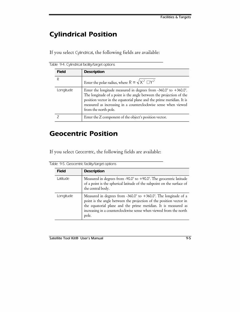
Facilities & Targets
Satellite Tool Kit® User’s Manual 9-5
Cylindrical Position
If you select Cylindrical, the following fields are available:
Table 9-4. Cylindrical facility/target options
Field Description
REnter the polar radius, where 5 ; <= +2 2
Longitude Enter the longitude measured in degrees from -360.0° to +360.0°.The longitude of a point is the angle between the projection of theposition vector in the equatorial plane and the prime meridian. It ismeasured as increasing in a counterclockwise sense when viewedfrom the north pole.
Z Enter the Z component of the object’s position vector.
Geocentric Position
If you select Geocentric, the following fields are available:
Table 9-5. Geocentric facility/target options
Field Description
Latitude Measured in degrees from -90.0° to +90.0°. The geocentric latitudeof a point is the spherical latitude of the subpoint on the surface ofthe central body.
Longitude Measured in degrees from -360.0° to +360.0°. The longitude of apoint is the angle between the projection of the position vector inthe equatorial plane and the prime meridian. It is measured asincreasing in a counterclockwise sense when viewed from the northpole.
Facilities & Targets
9-6 Satellite Tool Kit® User’s Manual
Field Description
Altitude Specified above or below the reference ellipsoid. Altitude ismeasured along the normal to the surface of the ellipsoid.
Basic Properties: Az-El Mask
In the Az-El Mask tab, specify the type of data to be used for the facility’sazimuth, elevation and mask. If you choose Terrain, the data specified in theTerrain tab of the scenario’s Basic Properties window. If you specify Az-ElMask, enter the file name of the az-el mask file in the Mask field. The fileshould be in the format detailed in Appendix CAppendix C of this manual.
In the Height Adjustment option, specify the adjustment in height from theEarth’s surface to the facility’s or target’s true height. This is useful forpositioning a specific sensor or point of interest.
Terrain data doesn’t include structures such as buildings.
Refer to Appendix C for detailed information about file format requirements for importingdata into STK.
Graphics Properties: Attributes
The fields in the Attributes tab control the graphical display of the facility ortarget in the Map window.
PRO/PRO/TerrainTerrain
1RWH
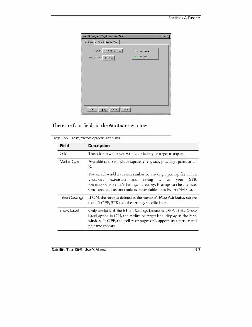
Facilities & Targets
Satellite Tool Kit® User’s Manual 9-7
There are four fields in the Attributes window.
Table 9-6. Facility/target graphic attributes
Field Description
Color The color in which you wish your facility or target to appear.
Marker Style Available options include square, circle, star, plus sign, point or anX.
You can also add a custom marker by creating a pixmap file with a.marker extension and saving it to your STK<Home>/STKData/Pixmaps directory. Pixmaps can be any size.Once created, custom markers are available in the Marker Style list.
Inherit Settings If ON, the settings defined in the scenario’s Map Attributes tab areused. If OFF, STK uses the settings specified here.
Show Label Only available if the Inherit Settings feature is OFF. If the ShowLabel option is ON, the facility or target label display in the Mapwindow. If OFF, the facility or target only appears as a marker andno name appears.
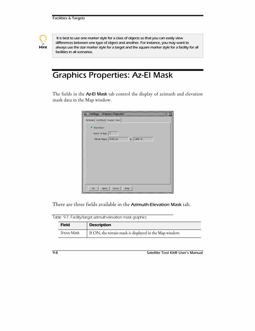
Facilities & Targets
9-8 Satellite Tool Kit® User’s Manual
It is best to use one marker style for a class of objects so that you can easily viewdifferences between one type of object and another. For instance, you may want toalways use the star marker style for a target and the square marker style for a facility for allfacilities in all scenarios.
Graphics Properties: Az-El Mask
The fields in the Az-El Mask tab control the display of azimuth and elevationmask data in the Map window.
There are three fields available in the Azimuth-Elevation Mask tab.
Table 9-7. Facility/target azimuth-elevation mask graphics
Field Description
Show Mask If ON, the terrain mask is displayed in the Map window.
+LQW
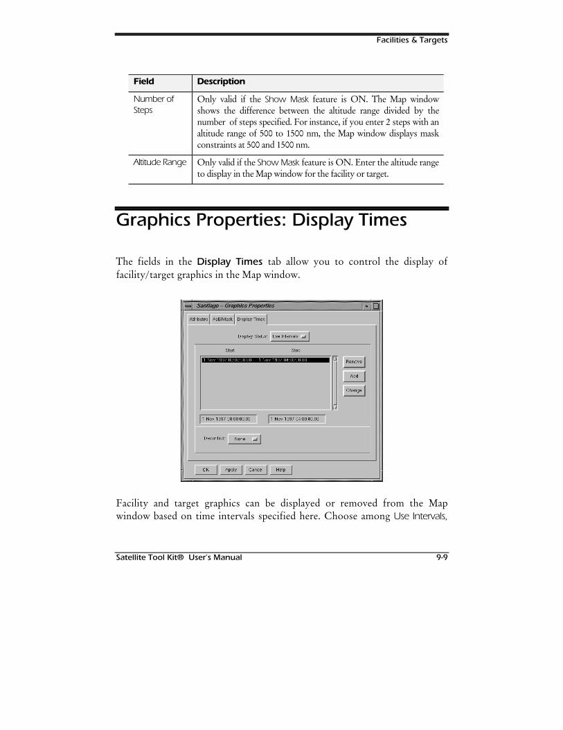
Facilities & Targets
Satellite Tool Kit® User’s Manual 9-9
Field Description
Number ofSteps
Only valid if the Show Mask feature is ON. The Map windowshows the difference between the altitude range divided by thenumber of steps specified. For instance, if you enter 2 steps with analtitude range of 500 to 1500 nm, the Map window displays maskconstraints at 500 and 1500 nm.
Altitude Range Only valid if the Show Mask feature is ON. Enter the altitude rangeto display in the Map window for the facility or target.
Graphics Properties: Display Times
The fields in the Display Times tab allow you to control the display offacility/target graphics in the Map window.
Facility and target graphics can be displayed or removed from the Mapwindow based on time intervals specified here. Choose among Use Intervals,
Facilities & Targets
9-10 Satellite Tool Kit® User’s Manual
Always On, or Always Off. If you choose the Use Intervals option, the Start andStop Times specified in the list box are used as the time intervals during whichfacility/target graphics display in the Map window. If you choose the AlwaysOn option, facility/target graphics always display in the Map window,regardless of the intervals specified in the list box. If you choose the AlwaysOff option, facility/target graphics never display in the Map window.
To specify the times during which facility/target graphics should display inthe Map window, enter the Start and Stop Times, then click on the Add button.Use the Change button to modify a time interval. Use the Remove button toremove a time period from the list.
You can also choose whether the time intervals should be “deconflicted,” ormodified so that time periods don’t overlap. If the Deconflict option is set toAutomatic, STK automatically modifies all time intervals during which anoverlap occurs so that the intervals are further segmented to avoid overlap. Ifthe option is set to None, no changes are made to time interval overlaps. Ifthe option is set to Manual, when an overlap occurs in the time interval list,an Acknowledge window appears when you click on the OK or Apply buttonto alert you to the fact that overlap(s) exists. It is then your decision whetherto set the Deconflict field to Automatic so that overlap(s) are fixed, change thetime intervals yourself by modifying the appropriate entries in the list box, orignore the message and continue.
Constraints: Basic
The fields in the Basic tab allow you to impose standard constraints for thefacility or target.
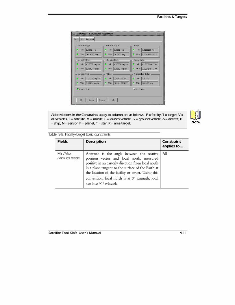
Facilities & Targets
Satellite Tool Kit® User’s Manual 9-11
Abbreviations in the Constraints apply to column are as follows: F = facility, T = target, V =all vehicles, S = satellite, M = missile, L = launch vehicle, G = ground vehicle, A = aircraft, B= ship, N = sensor, P = planet, * = star, R = area target.
Table 9-8. Facility/target basic constraints
Fields Description Constraintapplies to…
Min/MaxAzimuth Angle
Azimuth is the angle between the relativeposition vector and local north, measuredpositive in an easterly direction from local northin a plane tangent to the surface of the Earth atthe location of the facility or target. Using thisconvention, local north is at 0° azimuth, localeast is at 90° azimuth.
All
1RWH
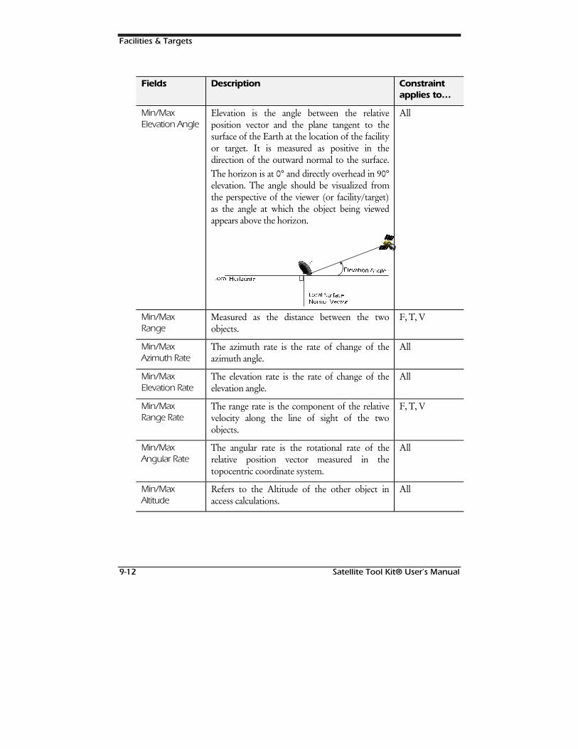
Facilities & Targets
9-12 Satellite Tool Kit® User’s Manual
Fields Description Constraintapplies to…
Min/MaxElevation Angle
Elevation is the angle between the relativeposition vector and the plane tangent to thesurface of the Earth at the location of the facilityor target. It is measured as positive in thedirection of the outward normal to the surface.The horizon is at 0° and directly overhead in 90°elevation. The angle should be visualized fromthe perspective of the viewer (or facility/target)as the angle at which the object being viewedappears above the horizon.
/R/RFFDODO ++RULRUL]]RRQWQWDDOO
((OHOHYDWLYDWLRQRQ $$QQJJOOHH
/R/RFFDODO 66XXUIDUIDFFHH11RUPRUPDO 9DO 9HFHFWWRURU
All
Min/MaxRange
Measured as the distance between the twoobjects.
F, T, V
Min/MaxAzimuth Rate
The azimuth rate is the rate of change of theazimuth angle.
All
Min/MaxElevation Rate
The elevation rate is the rate of change of theelevation angle.
All
Min/MaxRange Rate
The range rate is the component of the relativevelocity along the line of sight of the twoobjects.
F, T, V
Min/MaxAngular Rate
The angular rate is the rotational rate of therelative position vector measured in thetopocentric coordinate system.
All
Min/MaxAltitude
Refers to the Altitude of the other object inaccess calculations.
All
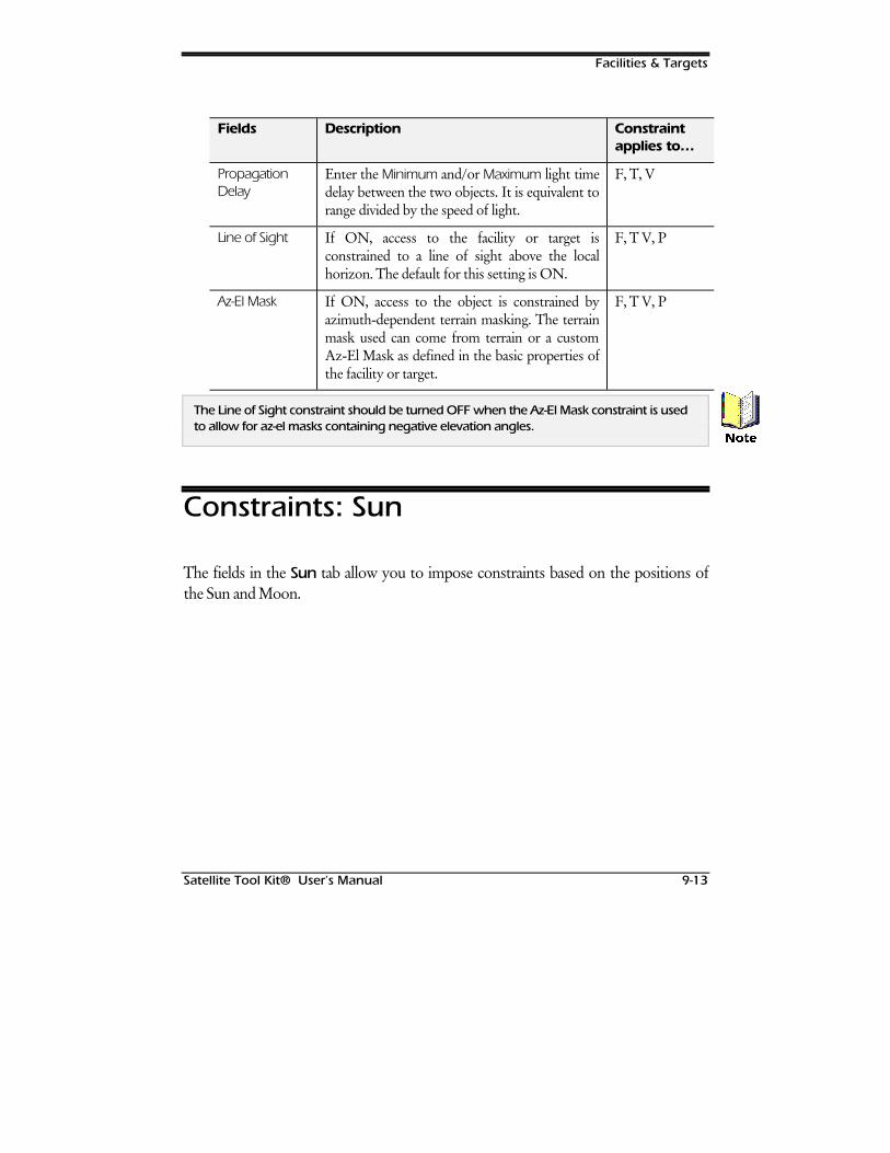
Facilities & Targets
Satellite Tool Kit® User’s Manual 9-13
Fields Description Constraintapplies to…
PropagationDelay
Enter the Minimum and/or Maximum light timedelay between the two objects. It is equivalent torange divided by the speed of light.
F, T, V
Line of Sight If ON, access to the facility or target isconstrained to a line of sight above the localhorizon. The default for this setting is ON.
F, T V, P
Az-El Mask If ON, access to the object is constrained byazimuth-dependent terrain masking. The terrainmask used can come from terrain or a customAz-El Mask as defined in the basic properties ofthe facility or target.
F, T V, P
The Line of Sight constraint should be turned OFF when the Az-El Mask constraint is usedto allow for az-el masks containing negative elevation angles.
Constraints: Sun
The fields in the Sun tab allow you to impose constraints based on the positions ofthe Sun and Moon.
1RWH
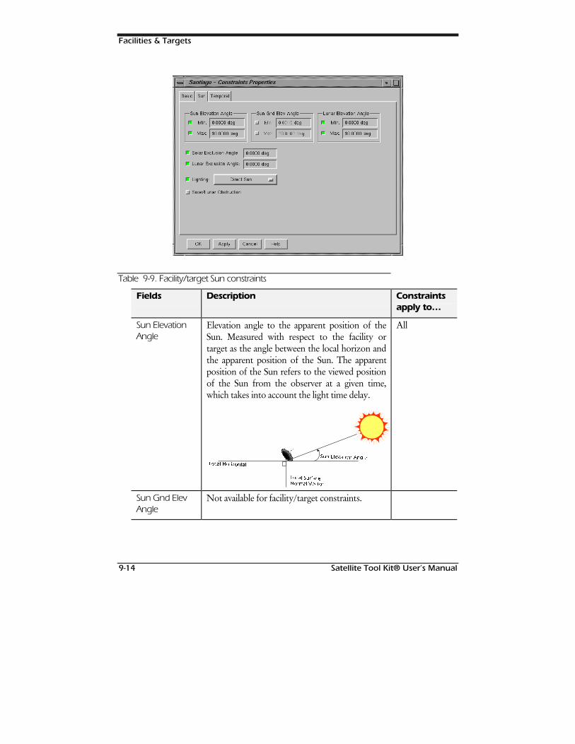
Facilities & Targets
9-14 Satellite Tool Kit® User’s Manual
Table 9-9. Facility/target Sun constraints
Fields Description Constraintsapply to…
Sun ElevationAngle
Elevation angle to the apparent position of theSun. Measured with respect to the facility ortarget as the angle between the local horizon andthe apparent position of the Sun. The apparentposition of the Sun refers to the viewed positionof the Sun from the observer at a given time,which takes into account the light time delay.
//RFRFDDOO ++RULRUL]]RQWRQWDODO
66XXQQ ((OOHHYYDDWLWLRQRQ $$QJQJOOHH
//RFRFDDOO 66XXUUIIDFDFHH11RURUPPDO 9DO 9HHFFWWRURU
All
Sun Gnd ElevAngle
Not available for facility/target constraints.
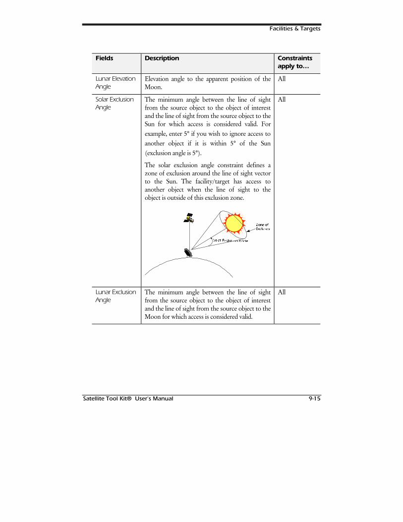
Facilities & Targets
Satellite Tool Kit® User’s Manual 9-15
Fields Description Constraintsapply to…
Lunar ElevationAngle
Elevation angle to the apparent position of theMoon.
All
Solar ExclusionAngle
The minimum angle between the line of sightfrom the source object to the object of interestand the line of sight from the source object to theSun for which access is considered valid. Forexample, enter 5° if you wish to ignore access toanother object if it is within 5° of the Sun(exclusion angle is 5°).
The solar exclusion angle constraint defines azone of exclusion around the line of sight vectorto the Sun. The facility/target has access toanother object when the line of sight to theobject is outside of this exclusion zone.
66RRODODUU (([[FFOOXXVVLLRQRQ $$QJOHQJOH
==RQH RRQH RII([([FFOOXVLRQXVLRQ
All
Lunar ExclusionAngle
The minimum angle between the line of sightfrom the source object to the object of interestand the line of sight from the source object to theMoon for which access is considered valid.
All
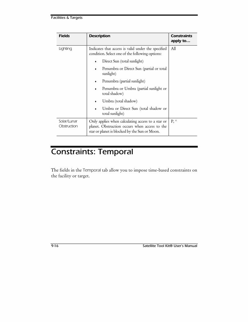
Facilities & Targets
9-16 Satellite Tool Kit® User’s Manual
Fields Description Constraintsapply to…
Lighting Indicates that access is valid under the specifiedcondition. Select one of the following options:
♦ Direct Sun (total sunlight)
♦ Penumbra or Direct Sun (partial or totalsunlight)
♦ Penumbra (partial sunlight)
♦ Penumbra or Umbra (partial sunlight ortotal shadow)
♦ Umbra (total shadow)
♦ Umbra or Direct Sun (total shadow ortotal sunlight)
All
Solar/LunarObstruction
Only applies when calculating access to a star orplanet. Obstruction occurs when access to thestar or planet is blocked by the Sun or Moon.
P, *
Constraints: Temporal
The fields in the Temporal tab allow you to impose time-based constraints onthe facility or target.
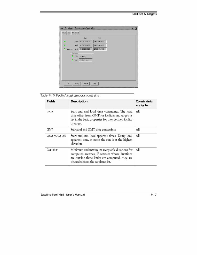
Facilities & Targets
Satellite Tool Kit® User’s Manual 9-17
Table 9-10. Facility/target temporal constraints
Fields Description Constraintsapply to…
Local Start and end local time constraints. The localtime offset from GMT for facilities and targets isset in the basic properties for the specified facilityor target.
All
GMT Start and end GMT time constraints. All
Local Apparent Start and end local apparent times. Using localapparent time, at noon the sun is at the highestelevation.
All
Duration Minimum and maximum acceptable durations forcomputed accesses. If accesses whose durationsare outside these limits are computed, they arediscarded from the resultant list.
All

Facilities & Targets
9-18 Satellite Tool Kit® User’s Manual
127(6
Satellite Tool Kit® User’s Manual 10-1
10AREA TARGETS
Overview
In some instances, you may need to define a target in terms of a geographicalarea instead of a specific point location on the Earth’s surface. STK providesyou with this ability through the use of area targets, which are definedseparately from targets.
Chapter Contents
Basic Properties: Boundary.........................................................................10-2
Basic Properties: Centroid...........................................................................10-3
Geodetic Position..................................................................................10-4
Spherical Position..................................................................................10-4
Cartesian Position..................................................................................10-5
Cylindrical Position ................................................................................10-5
Geocentric Position...............................................................................10-5
PRO/AdvancedAnalysis
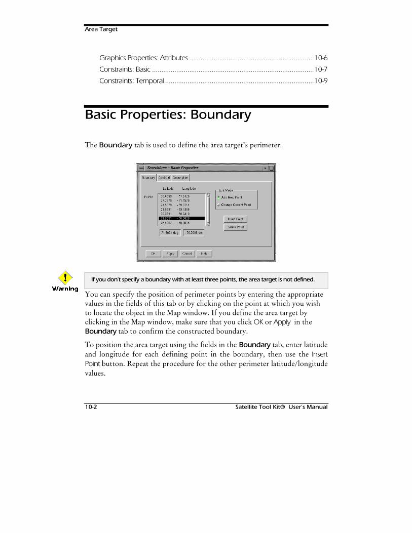
Area Target
10-2 Satellite Tool Kit® User’s Manual
Graphics Properties: Attributes ...................................................................10-6
Constraints: Basic .......................................................................................10-7
Constraints: Temporal ................................................................................10-9
Basic Properties: Boundary
The Boundary tab is used to define the area target’s perimeter.
If you don’t specify a boundary with at least three points, the area target is not defined.
You can specify the position of perimeter points by entering the appropriatevalues in the fields of this tab or by clicking on the point at which you wishto locate the object in the Map window. If you define the area target byclicking in the Map window, make sure that you click OK or Apply in theBoundary tab to confirm the constructed boundary.
To position the area target using the fields in the Boundary tab, enter latitudeand longitude for each defining point in the boundary, then use the InsertPoint button. Repeat the procedure for the other perimeter latitude/longitudevalues.
:DUQLQJ
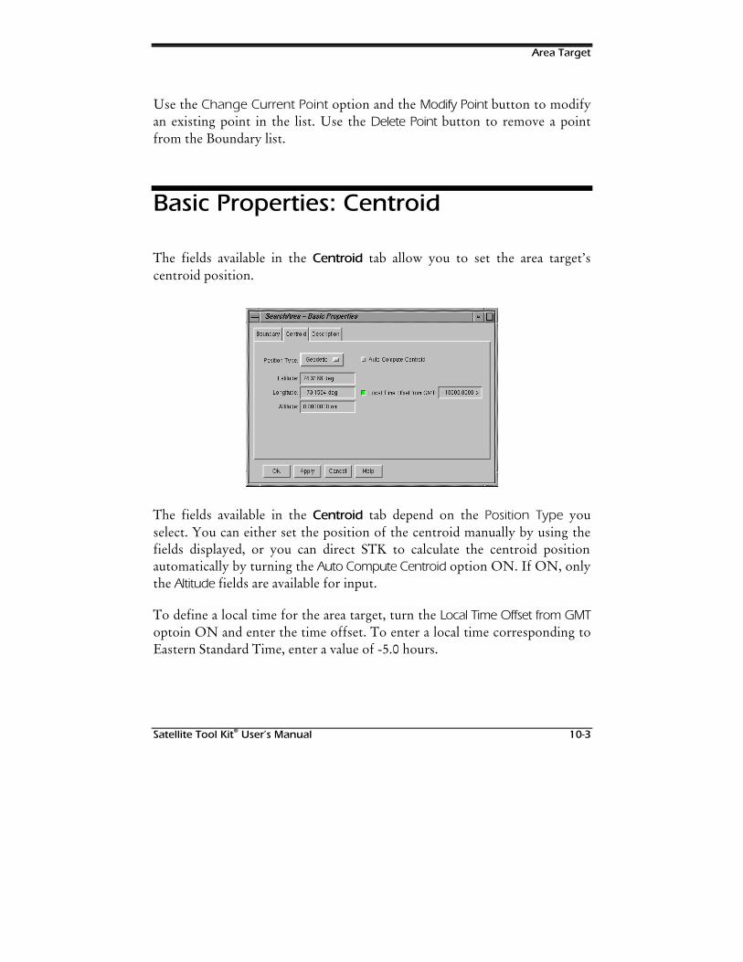
Area Target
Satellite Tool Kit® User’s Manual 10-3
Use the Change Current Point option and the Modify Point button to modifyan existing point in the list. Use the Delete Point button to remove a pointfrom the Boundary list.
Basic Properties: Centroid
The fields available in the Centroid tab allow you to set the area target’scentroid position.
The fields available in the Centroid tab depend on the Position Type youselect. You can either set the position of the centroid manually by using thefields displayed, or you can direct STK to calculate the centroid positionautomatically by turning the Auto Compute Centroid option ON. If ON, onlythe Altitude fields are available for input.
To define a local time for the area target, turn the Local Time Offset from GMToptoin ON and enter the time offset. To enter a local time corresponding toEastern Standard Time, enter a value of -5.0 hours.
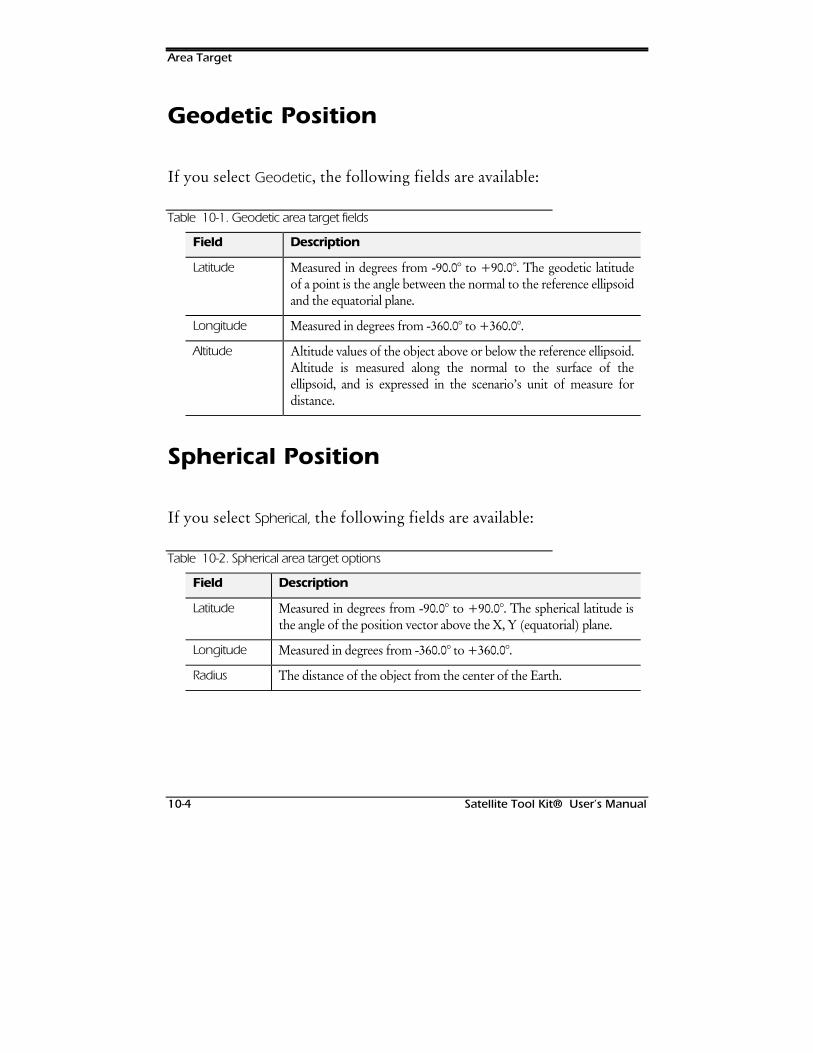
Area Target
10-4 Satellite Tool Kit® User’s Manual
Geodetic Position
If you select Geodetic, the following fields are available:
Table 10-1. Geodetic area target fields
Field Description
Latitude Measured in degrees from -90.0° to +90.0°. The geodetic latitudeof a point is the angle between the normal to the reference ellipsoidand the equatorial plane.
Longitude Measured in degrees from -360.0° to +360.0°.
Altitude Altitude values of the object above or below the reference ellipsoid.Altitude is measured along the normal to the surface of theellipsoid, and is expressed in the scenario’s unit of measure fordistance.
Spherical Position
If you select Spherical, the following fields are available:
Table 10-2. Spherical area target options
Field Description
Latitude Measured in degrees from -90.0° to +90.0°. The spherical latitude isthe angle of the position vector above the X, Y (equatorial) plane.
Longitude Measured in degrees from -360.0° to +360.0°.
Radius The distance of the object from the center of the Earth.

Area Target
Satellite Tool Kit® User’s Manual 10-5
Cartesian Position
If you select Cartesian, the following fields are available:
Table 10-3. Cartesian area target options
Field Description
X The X component of the object’s position vector, where the X axiscrosses 0° latitude/0° longitude.
Y The Y component of the object’s position vector.
Z The Z component of the object’s position vector, where the Z axispoints to the North pole.
Cylindrical Position
If you select Cylindrical, the following fields are available:
Table 10-4. Cylindrical area target options
Field Description
RThe polar radius, where R x y= +2 2
Longitude The longitude measured in degrees from -360.0° to +360.0°.
Z The Z component of the object’s position vector.
Geocentric Position
If you select Geocentric, the following fields are available:
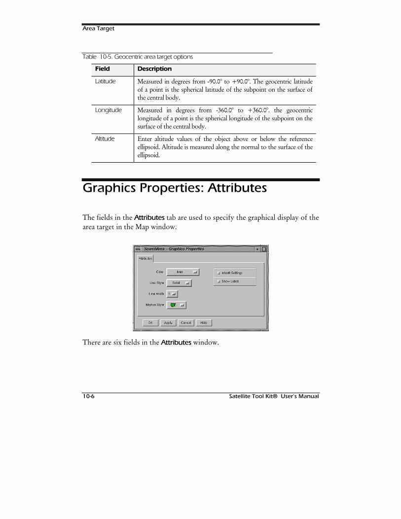
Area Target
10-6 Satellite Tool Kit® User’s Manual
Table 10-5. Geocentric area target options
Field Description
Latitude Measured in degrees from -90.0° to +90.0°. The geocentric latitudeof a point is the spherical latitude of the subpoint on the surface ofthe central body.
Longitude Measured in degrees from -360.0° to +360.0°. the geocentriclongitude of a point is the spherical longitude of the subpoint on thesurface of the central body.
Altitude Enter altitude values of the object above or below the referenceellipsoid. Altitude is measured along the normal to the surface of theellipsoid.
Graphics Properties: Attributes
The fields in the Attributes tab are used to specify the graphical display of thearea target in the Map window.
There are six fields in the Attributes window.
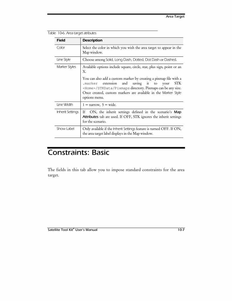
Area Target
Satellite Tool Kit® User’s Manual 10-7
Table 10-6. Area target atributes
Field Description
Color Select the color in which you wish the area target to appear in theMap window.
Line Style Choose among Solid, Long Dash, Dotted, Dot Dash or Dashed.
Marker Styles Available options include square, circle, star, plus sign, point or anX.
You can also add a custom marker by creating a pixmap file with a.marker extension and saving it to your STK<Home>/STKData/Pixmaps directory. Pixmaps can be any size.Once created, custom markers are available in the Marker Styleoptions menu.
Line Width 1 = narrow, 5 = wide.
Inherit Settings If ON, the inherit settings defined in the scenario’s MapAttributes tab are used. If OFF, STK ignores the inherit settingsfor the scenario.
Show Label Only available if the Inherit Settings feature is turned OFF. If ON,the area target label displays in the Map window.
Constraints: Basic
The fields in this tab allow you to impose standard constraints for the areatarget.
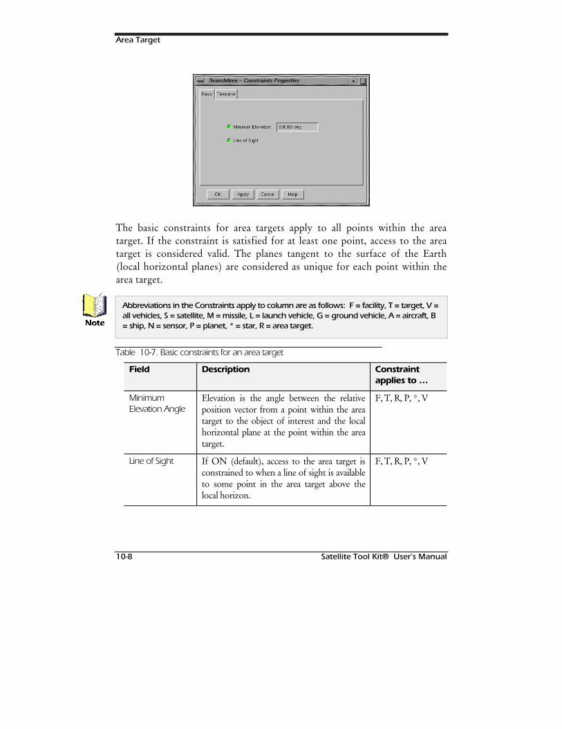
Area Target
10-8 Satellite Tool Kit® User’s Manual
The basic constraints for area targets apply to all points within the areatarget. If the constraint is satisfied for at least one point, access to the areatarget is considered valid. The planes tangent to the surface of the Earth(local horizontal planes) are considered as unique for each point within thearea target.
Abbreviations in the Constraints apply to column are as follows: F = facility, T = target, V =all vehicles, S = satellite, M = missile, L = launch vehicle, G = ground vehicle, A = aircraft, B= ship, N = sensor, P = planet, * = star, R = area target.
Table 10-7. Basic constraints for an area target
Field Description Constraintapplies to …
MinimumElevation Angle
Elevation is the angle between the relativeposition vector from a point within the areatarget to the object of interest and the localhorizontal plane at the point within the areatarget.
F, T, R, P, *, V
Line of Sight If ON (default), access to the area target isconstrained to when a line of sight is availableto some point in the area target above thelocal horizon.
F, T, R, P, *, V
1RWH
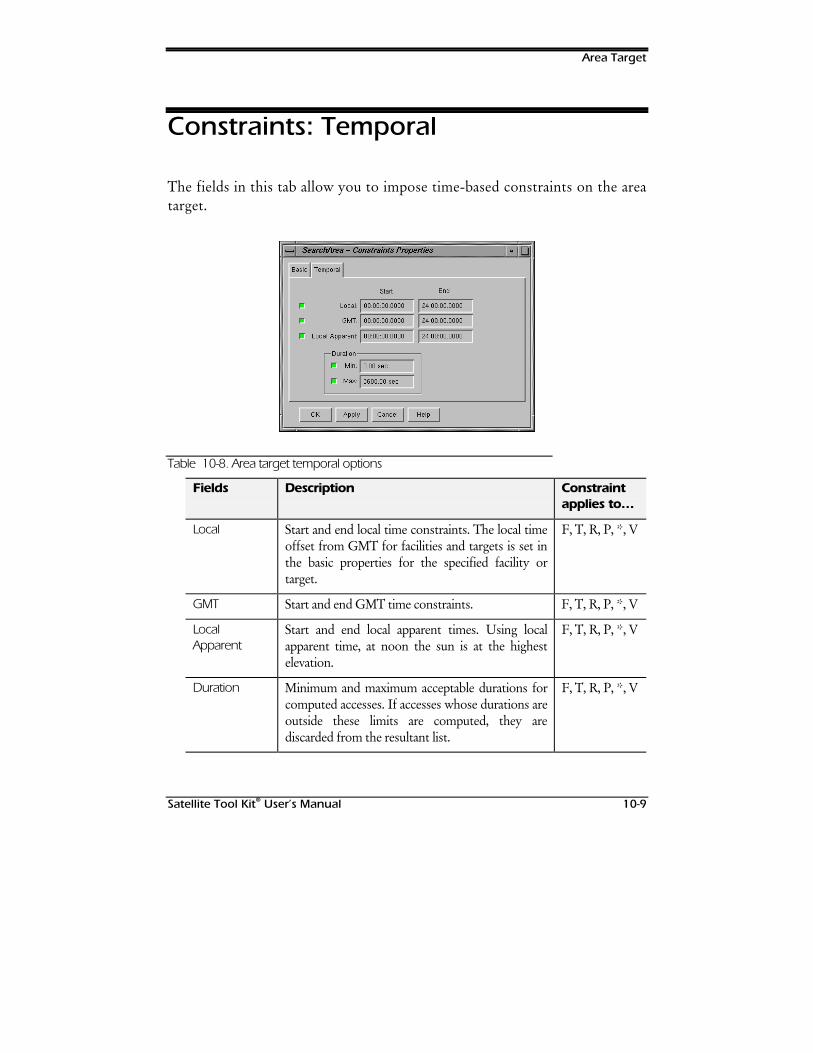
Area Target
Satellite Tool Kit® User’s Manual 10-9
Constraints: Temporal
The fields in this tab allow you to impose time-based constraints on the areatarget.
Table 10-8. Area target temporal options
Fields Description Constraintapplies to…
Local Start and end local time constraints. The local timeoffset from GMT for facilities and targets is set inthe basic properties for the specified facility ortarget.
F, T, R, P, *, V
GMT Start and end GMT time constraints. F, T, R, P, *, V
LocalApparent
Start and end local apparent times. Using localapparent time, at noon the sun is at the highestelevation.
F, T, R, P, *, V
Duration Minimum and maximum acceptable durations forcomputed accesses. If accesses whose durations areoutside these limits are computed, they arediscarded from the resultant list.
F, T, R, P, *, V

Area Target
10-10 Satellite Tool Kit® User’s Manual
Area targets are assumed to exist within a single time zone so that there is only one localtime offset from GMT. The local apparent time is computed based on the location of theCentroid.1RWH

Satellite Tool Kit® User’s Manual 11-1
11STARS & PLANETS
Overview
STK provides you with the opportunity to conduct detailed analysesinvolving numerous and varied objects in a scenario. Complex scenariosoften require the inclusion of stars and planets to provide a complete analysisof sensor in-view opportunities. In STK, stars are used to represent“stationary” objects such as stars, quasars and pulsars. Planets representobjects in heliocentric orbit such as planets, minor planets, asteroids andcomets. For your convenience, the Moon and the Sun are also included in thePlanet class.
Chapter Contents
Basic Properties: Defining a Star .................................................................11-2
Basic Properties: Defining a Planet .............................................................11-3
Graphic Properties: Star/Planet Attributes...................................................11-4
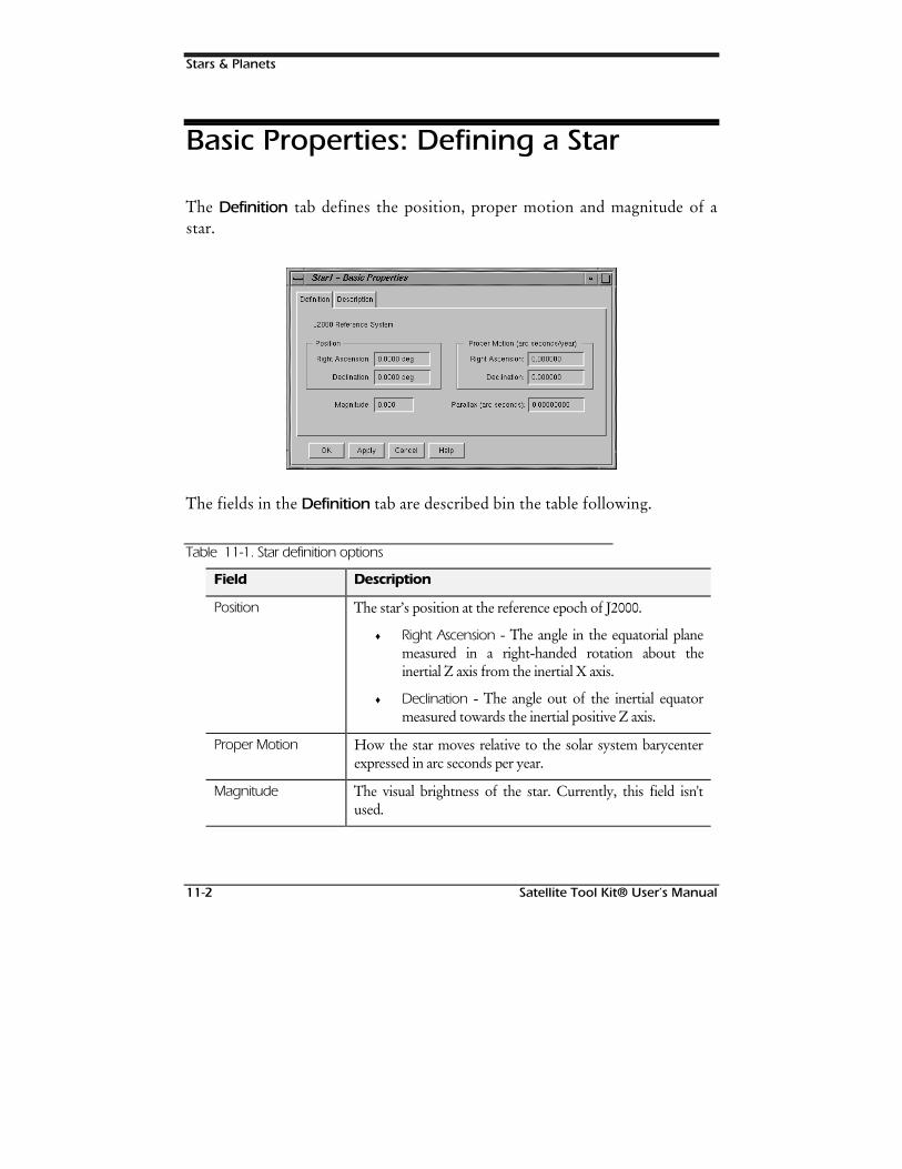
Stars & Planets
11-2 Satellite Tool Kit® User’s Manual
Basic Properties: Defining a Star
The Definition tab defines the position, proper motion and magnitude of astar.
The fields in the Definition tab are described bin the table following.
Table 11-1. Star definition options
Field Description
Position The star’s position at the reference epoch of J2000.
♦ Right Ascension - The angle in the equatorial planemeasured in a right-handed rotation about theinertial Z axis from the inertial X axis.
♦ Declination - The angle out of the inertial equatormeasured towards the inertial positive Z axis.
Proper Motion How the star moves relative to the solar system barycenterexpressed in arc seconds per year.
Magnitude The visual brightness of the star. Currently, this field isn'tused.
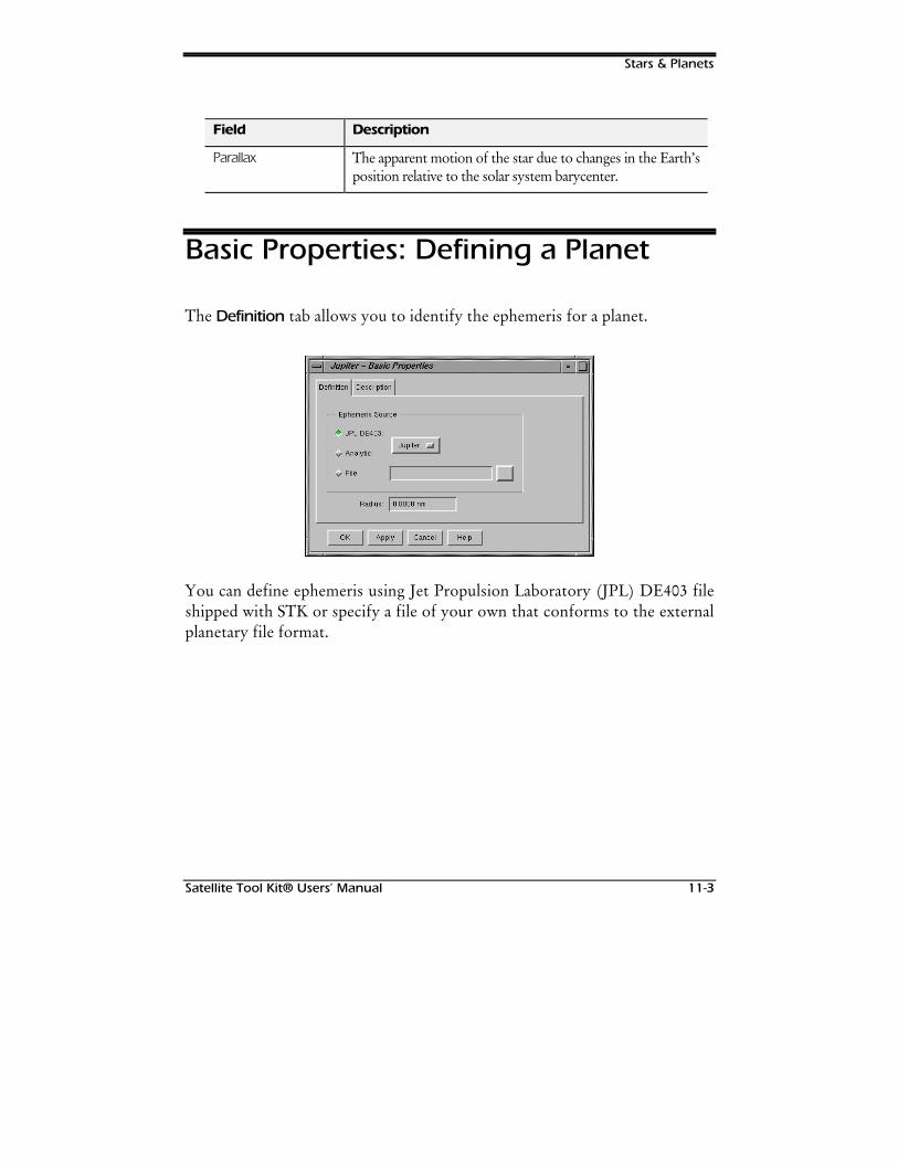
Stars & Planets
Satellite Tool Kit® Users’ Manual 11-3
Field Description
Parallax The apparent motion of the star due to changes in the Earth’sposition relative to the solar system barycenter.
Basic Properties: Defining a Planet
The Definition tab allows you to identify the ephemeris for a planet.
You can define ephemeris using Jet Propulsion Laboratory (JPL) DE403 fileshipped with STK or specify a file of your own that conforms to the externalplanetary file format.
Stars & Planets
11-4 Satellite Tool Kit® User’s Manual
Table 11-2. Planet definition elements
Field Description
Ephemeris Source Specify one:
♦ JPL DE403 -STK is shipped with a database ofephemeris for each planet in our solar system plusthe Sun and Moon. Ephemerides, supplied by JPL,cover a time span from 1960 to 2060.
♦ Analytic - Analytic representation of a planet’s stateas a reference of time.
♦ File - An external ephemeris file used to define theplanet.
Radius Radius values1 update automatically when you choose a JPLDE403 file.
Graphic Properties: Star/PlanetAttributes
The Attributes tab allows you to specify the graphical display of the star orplanet in the Map window.
1 James R. Wertz (ed.), Spacecraft Attitude Determination and Control,Kluwer Academic Publishers, 1990, p. 816, Table L-2.
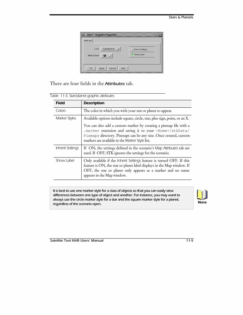
Stars & Planets
Satellite Tool Kit® Users’ Manual 11-5
There are four fields in the Attributes tab.
Table 11-3. Star/planet graphic attributes
Field Description
Colors The color in which you wish your star or planet to appear.
Marker Styles Available options include square, circle, star, plus sign, point, or an X.
You can also add a custom marker by creating a pixmap file with a.marker extension and saving it to your <Home>/stkData/Pixmaps directory. Pixmaps can be any size. Once created, custommarkers are available in the Marker Style list.
Inherit Settings If ON, the settings defined in the scenario’s Map Attributes tab areused. If OFF, STK ignores the settings for the scenario.
Show Label Only available if the Inherit Settings feature is turned OFF. If thisfeature is ON, the star or planet label displays in the Map window. IfOFF, the star or planet only appears as a marker and no nameappears in the Map window.
It is best to use one marker style for a class of objects so that you can easily viewdifferences between one type of object and another. For instance, you may want toalways use the circle marker style for a star and the square marker style for a planet,regardless of the scenario open. 1RWH

Stars & Planets
11-6 Satellite Tool Kit® User’s Manual
127(6
Satellite Tool Kit® User’s Manual 12-1
12SENSORS
Overview
Sensors and sensor performance are a major concern for satellite systemsengineers and integrators who analyze and design current and future systems.In STK, the sensor’s field of view must be defined and its orientation relativeto its parent object must be specified.
Sensors can be used to represent such equipment as optical or radar sensors,receiving or transmitting antennas, and lasers. They can also be used to defineanother object’s field of view. Although sensors are objects, they aresubordinate to, or subobjects of, vehicles, targets or facilities.
When you change the properties of a sensor during an STK session, none ofthe changes are saved to the sensor’s file until you save either the sensor itselfor the owner of the sensor (i.e., the facility, target or vehicle to which thesensor is attached). For example, you can attach the same sensor to multiplevehicles within a given scenario and make changes to individual sensors sothat they exhibit different characteristics during animation. If you save theentire scenario, the properties of the last sensor saved define and overwritethe properties of any like-named versions of that sensor.
Sensors
12-2 Satellite Tool Kit® User’s Manual
Chapter Contents
Basic Properties: Definition.........................................................................12-2
Conic Sensor.........................................................................................12-3
Half-Power Sensor.................................................................................12-4
Custom Sensor......................................................................................12-6
Rectangular Sensor...............................................................................12-8
Basic Properties: Pointing a Sensor.............................................................12-9
Fixed Sensor Pointing .........................................................................12-10
Targeting a Sensor..............................................................................12-13
External Pointing Files .........................................................................12-16
Basic Properties: Resolution......................................................................12-16
Graphics Properties: Sensor Attributes......................................................12-17
Graphics Properties: Projection ................................................................12-18
Graphics Properties: Display Times...........................................................12-20
Constraints: Basic .....................................................................................12-21
Constraints: Sun.......................................................................................12-22
Constraints: Temporal ..............................................................................12-24
Constraints: Advanced.............................................................................12-24
Constraints: Resolution.............................................................................12-25
Basic Properties: Definition
You can define a sensor in any of the following ways: simple or complexconic projection, half-power beam width or a custom pattern. The fields inthe Definition tab depend upon the type of sensor you choose.
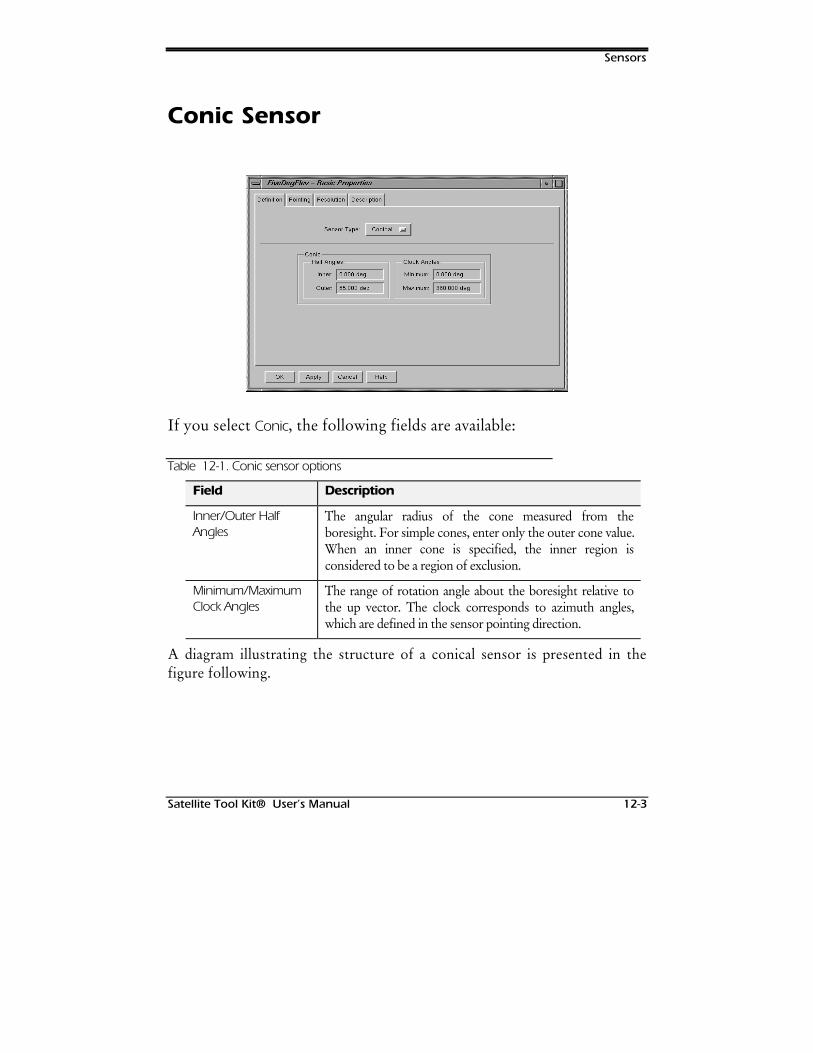
Sensors
Satellite Tool Kit® User’s Manual 12-3
Conic Sensor
If you select Conic, the following fields are available:
Table 12-1. Conic sensor options
Field Description
Inner/Outer HalfAngles
The angular radius of the cone measured from theboresight. For simple cones, enter only the outer cone value.When an inner cone is specified, the inner region isconsidered to be a region of exclusion.
Minimum/MaximumClock Angles
The range of rotation angle about the boresight relative tothe up vector. The clock corresponds to azimuth angles,which are defined in the sensor pointing direction.
A diagram illustrating the structure of a conical sensor is presented in thefigure following.
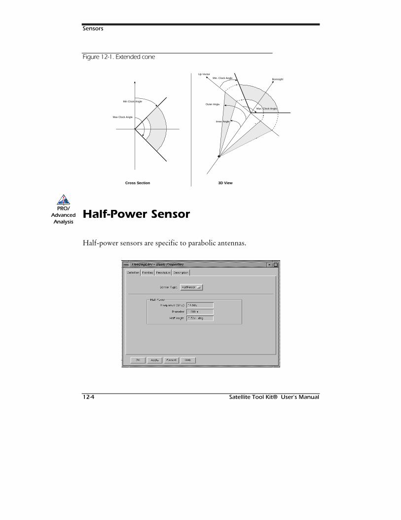
Sensors
12-4 Satellite Tool Kit® User’s Manual
Figure 12-1. Extended cone
Max Clock Angle
Min Clock Angle
Cross Section
Min. Clock Angle
Outer Angle
Boresight
3D View
Up Vector
Inner Angle
Max. Clock Angle
Half-Power Sensor
Half-power sensors are specific to parabolic antennas.
PRO/AdvancedAnalysis
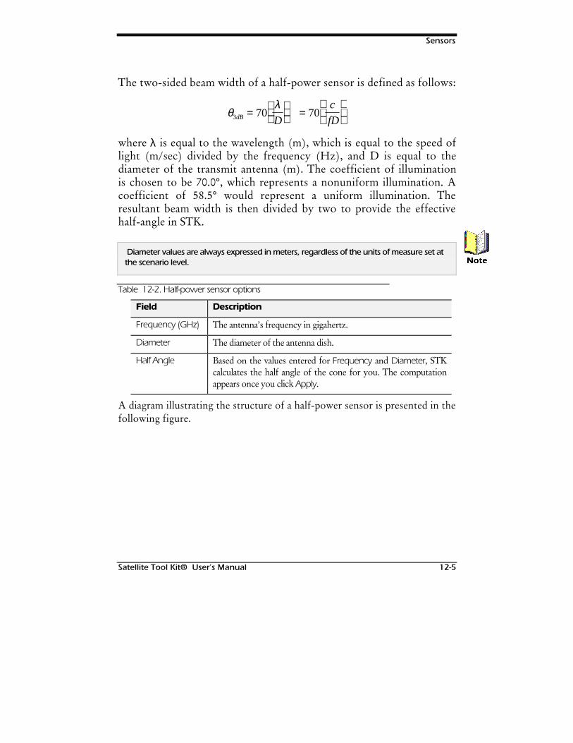
Sensors
Satellite Tool Kit® User’s Manual 12-5
The two-sided beam width of a half-power sensor is defined as follows:
θλ
3 70 70dB D
c
fD=
=
where λ is equal to the wavelength (m), which is equal to the speed oflight (m/sec) divided by the frequency (Hz), and D is equal to thediameter of the transmit antenna (m). The coefficient of illuminationis chosen to be 70.0°, which represents a nonuniform illumination. Acoefficient of 58.5° would represent a uniform illumination. Theresultant beam width is then divided by two to provide the effectivehalf-angle in STK.
Diameter values are always expressed in meters, regardless of the units of measure set atthe scenario level.
Table 12-2. Half-power sensor options
Field Description
Frequency (GHz) The antenna’s frequency in gigahertz.
Diameter The diameter of the antenna dish.
Half Angle Based on the values entered for Frequency and Diameter, STKcalculates the half angle of the cone for you. The computationappears once you click Apply.
A diagram illustrating the structure of a half-power sensor is presented in thefollowing figure.
1RWH
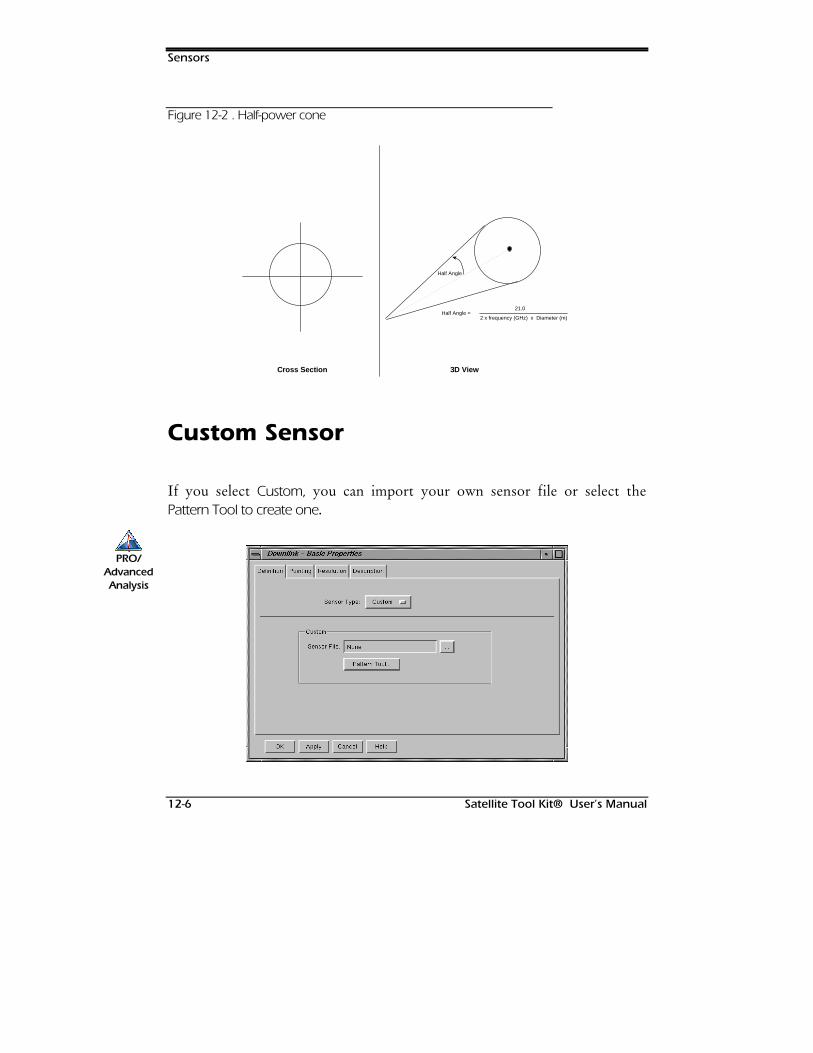
Sensors
12-6 Satellite Tool Kit® User’s Manual
Figure 12-2 . Half-power cone
Cross Section
Half Angle
Half Angle = 21.0
2 x frequency (GHz) x Diameter (m)
3D View
Custom Sensor
If you select Custom, you can import your own sensor file or select thePattern Tool to create one.
PRO/AdvancedAnalysis
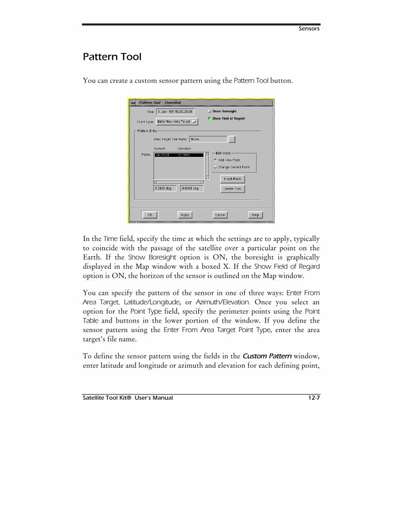
Sensors
Satellite Tool Kit® User’s Manual 12-7
Pattern Tool
You can create a custom sensor pattern using the Pattern Tool button.
In the Time field, specify the time at which the settings are to apply, typicallyto coincide with the passage of the satellite over a particular point on theEarth. If the Show Boresight option is ON, the boresight is graphicallydisplayed in the Map window with a boxed X. If the Show Field of Regardoption is ON, the horizon of the sensor is outlined on the Map window.
You can specify the pattern of the sensor in one of three ways: Enter FromArea Target, Latitude/Longitude, or Azimuth/Elevation. Once you select anoption for the Point Type field, specify the perimeter points using the PointTable and buttons in the lower portion of the window. If you define thesensor pattern using the Enter From Area Target Point Type, enter the areatarget’s file name.
To define the sensor pattern using the fields in the Custom Pattern window,enter latitude and longitude or azimuth and elevation for each defining point,
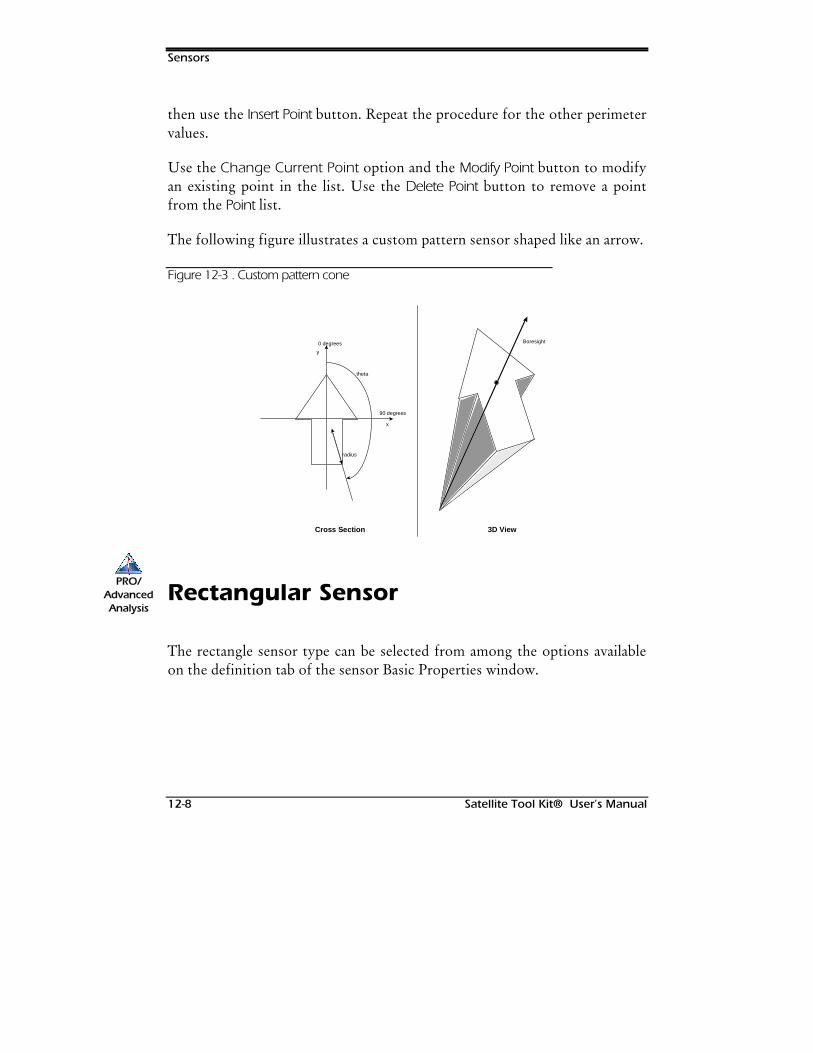
Sensors
12-8 Satellite Tool Kit® User’s Manual
then use the Insert Point button. Repeat the procedure for the other perimetervalues.
Use the Change Current Point option and the Modify Point button to modifyan existing point in the list. Use the Delete Point button to remove a pointfrom the Point list.
The following figure illustrates a custom pattern sensor shaped like an arrow.
Figure 12-3 . Custom pattern cone
Cross Section
90 degrees
0 degrees
theta
radius
x
y
3D View
Boresight
Rectangular Sensor
The rectangle sensor type can be selected from among the options availableon the definition tab of the sensor Basic Properties window.
PRO/AdvancedAnalysis
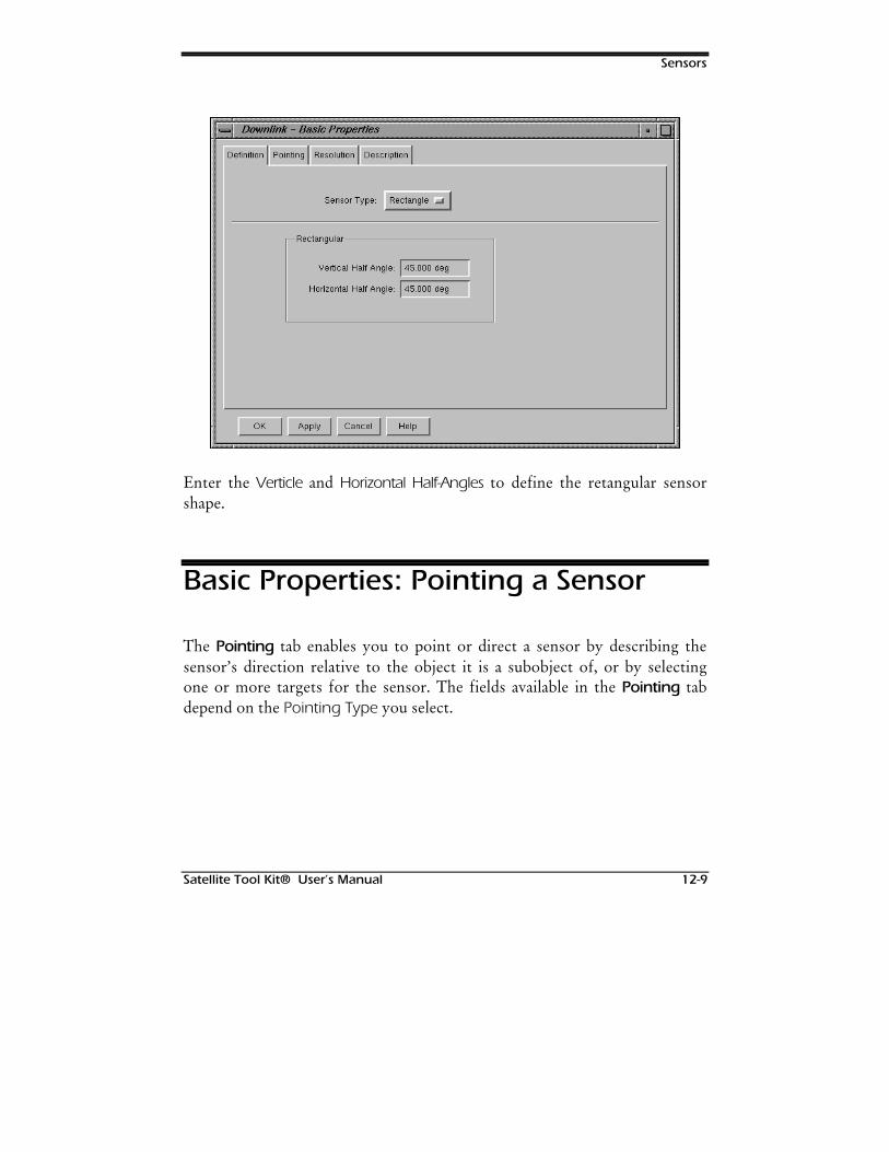
Sensors
Satellite Tool Kit® User’s Manual 12-9
Enter the Verticle and Horizontal Half-Angles to define the retangular sensorshape.
Basic Properties: Pointing a Sensor
The Pointing tab enables you to point or direct a sensor by describing thesensor’s direction relative to the object it is a subobject of, or by selectingone or more targets for the sensor. The fields available in the Pointing tabdepend on the Pointing Type you select.
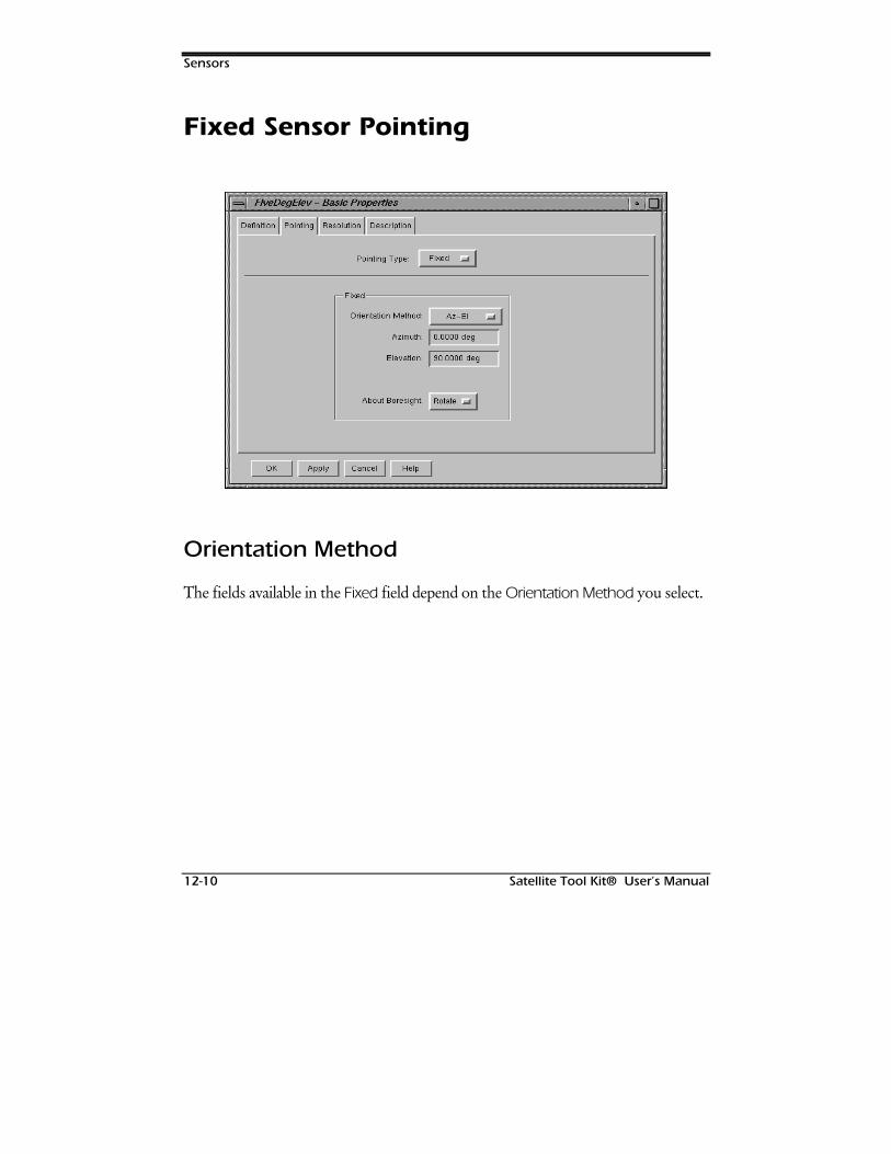
Sensors
12-10 Satellite Tool Kit® User’s Manual
Fixed Sensor Pointing
Orientation Method
The fields available in the Fixed field depend on the Orientation Method you select.
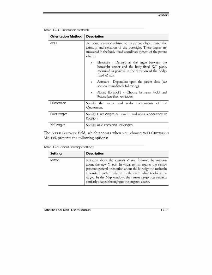
Sensors
Satellite Tool Kit® User’s Manual 12-11
Table 12-3. Orientation methods
Orientation Method Description
Az-El To point a sensor relative to its parent object, enter theazimuth and elevation of the boresight. These angles aremeasured in the body-fixed coordinate system of the parentobject.
♦ Elevation - Defined as the angle between theboresight vector and the body-fixed X,Y plane,measured as positive in the direction of the body-fixed -Z axis.
♦ Azimuth - Dependent upon the parent class (seesection immediately following).
♦ About Boresight - Choose between Hold andRotate (see the next table).
Quaternion Specify the vector and scalar components of theQuaternion.
Euler Angles Specify Euler Angles A, B and C and select a Sequence ofRotation.
YPR Angles Specify Yaw, Pitch and Roll Angles.
The About Boresight field, which appears when you choose Az-El OrientationMethod, presents the following options:
Table 12-4. About Boresight settings
Setting Description
Rotate Rotation about the sensor’s Z axis, followed by rotationabout the new Y axis. In visual terms: rotates the sensorpattern's general orientation about the boresight to maintaina constant pattern relative to the earth while tracking thetarget. In the Map window, the sensor projection remainssimilarly shaped throughout the targeted access.
Sensors
12-12 Satellite Tool Kit® User’s Manual
Setting Description
Hold Rotation about the Y axis followed by rotation about thenew X axis. In visual terms: holds a fixed orientation aboutthe boresight while tracking the target. This means that theshape of the sensor pattern isn’t constant, and the accesscalculations are different.
Facility/Target-Based Fixed Sensors
The definition of the Azimuth Angle is dependent upon the parent objectclass. For facility- or target-based sensors, azimuth is measured from thesensor “up” vector in a left-handed sense about the sensor boresight. For thedefault elevation of 90°, the up vector points toward local north and azimuthis measured as positive in an easterly direction. If the elevation is not 90° fora facility-based sensor, the up vector is defined as:
Upx = sin (elevation) cos (azimuth)
Upy = sin (elevation) sin (azimuth)
Upz = cos (elevation)
where X, Y and Z are facility body-fixed coordinates (X points to local north,Y points to local east, and Z points along the inward normal to the referenceellipsoid).
Vehicle-Based Fixed Sensors
For a vehicle-based sensor (such as satellites, aircraft, ground vehicles, etc),azimuth is measured from the sensor up vector in a right-handed sense aboutthe sensor boresight. For the default elevation of -90° and the defaultattitude, the up vector points toward the projection of the Earth-fixed
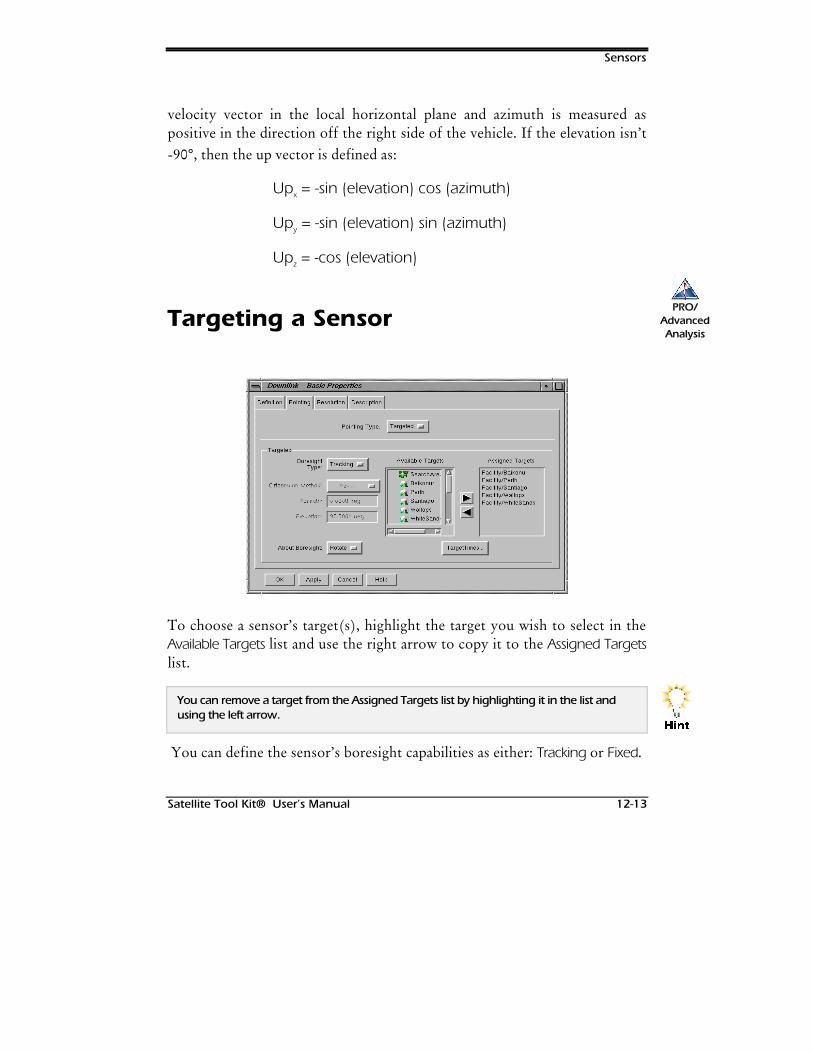
Sensors
Satellite Tool Kit® User’s Manual 12-13
velocity vector in the local horizontal plane and azimuth is measured aspositive in the direction off the right side of the vehicle. If the elevation isn’t-90°, then the up vector is defined as:
Upx = -sin (elevation) cos (azimuth)
Upy = -sin (elevation) sin (azimuth)
Upz = -cos (elevation)
Targeting a Sensor
To choose a sensor’s target(s), highlight the target you wish to select in theAvailable Targets list and use the right arrow to copy it to the Assigned Targetslist.
You can remove a target from the Assigned Targets list by highlighting it in the list andusing the left arrow.
You can define the sensor’s boresight capabilities as either: Tracking or Fixed.
PRO/AdvancedAnalysis
+LQW
Sensors
12-14 Satellite Tool Kit® User’s Manual
Tracking Boresight
Select this option to aim a sensor at one or more targets (i.e., facility, vehicleand/or target). The sensor’s footprint only appears on the map when a giventarget is in view, as determined by the sensor constraints and the targetedobject’s constraints. As the sensor tracks a target, its footprint changes shapeuntil the target is no longer in sight. A targeted tracking sensor actually slewsor tracks its assigned targets as soon as one of its targets appears over thehorizon. No relative pointing is defined for this type of sensor.
Fixed Boresight
Select this option to point a sensor by providing azimuth and elevation valuesfor the sensor’s boresight. Since this is a targeted sensor, its footprint onlydisplays in the Map window when a target is in view. However, the sensoralways points in a fixed direction. The pointing of the sensor isn’t affected bythe target chosen. The sensor appears during animation only if one of theassigned targets is visible within the defined view.
The body-fixed -Z axis for a facility or target points toward zenith and for a vehicle isattitude dependent. For the STK default attitude, with body-fixed +Z towards nadir,positive elevation angles point sensors away from the Earth. The default elevation angles
are +90° for facility and target-based sensors and -90° for vehicle-based sensors.
Orientation Method
The orientation methods available for the Targeted Pointing Type are the sameas those for the Fixed Pointing Type, discussed on page 12-10.
1RWH
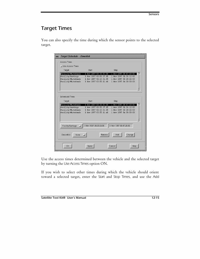
Sensors
Satellite Tool Kit® User’s Manual 12-15
Target Times
You can also specify the time during which the sensor points to the selectedtarget.
Use the access times determined between the vehicle and the selected targetby turning the Use Access Times option ON.
If you wish to select other times during which the vehicle should orienttoward a selected target, enter the Start and Stop Times, and use the Add
Sensors
12-16 Satellite Tool Kit® User’s Manual
button. Use the Change button to modify an existing value. Use the Removebutton to remove a time period from the Scheduled Times list.
You can also choose whether the time intervals should be “deconflicted,” ormodified so that time periods set don’t overlap. If the Deconflict field is set toAutomatic, STK automatically modifies all time intervals during which anoverlap occurs so that the intervals are further segmented to avoid overlap. Ifthe field is set to None, no changes are made to time interval overlaps. If thefield is set to Manual, when an overlap occurs in the time interval list, anAcknowledge window appears when you click the OK or Apply button to alertyou to the fact that the overlap exists. It is then your decision whether to setthe Deconflict field to Automatic so that the overlap is fixed, change the timeintervals yourself by modifying the appropriate entries in the list box, orignore the message and continue. The sensor target can be selected from thelist of assigned targets.
External Pointing Files
If you wish to use an external sensor file, select External as the Pointing Type,then specify the correct the file name.
Basic Properties: Resolution
The Resolution tab enables you to define the resolution of the sensor interms of focus and image quality.
PRO/AdvancedAnalysis

Sensors
Satellite Tool Kit® User’s Manual 12-17
In the Focus Constants field, enter the focal length and detector pitch of theoptical sensor. These constants are used in the computation of the GroundSample Distance (GSD) for the sensor. The GSD is computed as:
*6' GHWHFWRU SLWFKUDQJH
IRFDO OHQJWK VLQ HOHYDWLRQ
Graphics Properties: Sensor Attributes
The fields in the Attributes tab allow you to specify the graphical display ofthe sensor in the Map window.
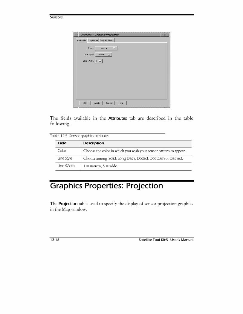
Sensors
12-18 Satellite Tool Kit® User’s Manual
The fields available in the Attributes tab are described in the tablefollowing.
Table 12-5. Sensor graphics attributes
Field Description
Color Choose the color in which you wish your sensor pattern to appear.
Line Style Choose among Solid, Long Dash, Dotted, Dot Dash or Dashed.
Line Width 1 = narrow, 5 = wide.
Graphics Properties: Projection
The Projection tab is used to specify the display of sensor projection graphicsin the Map window.
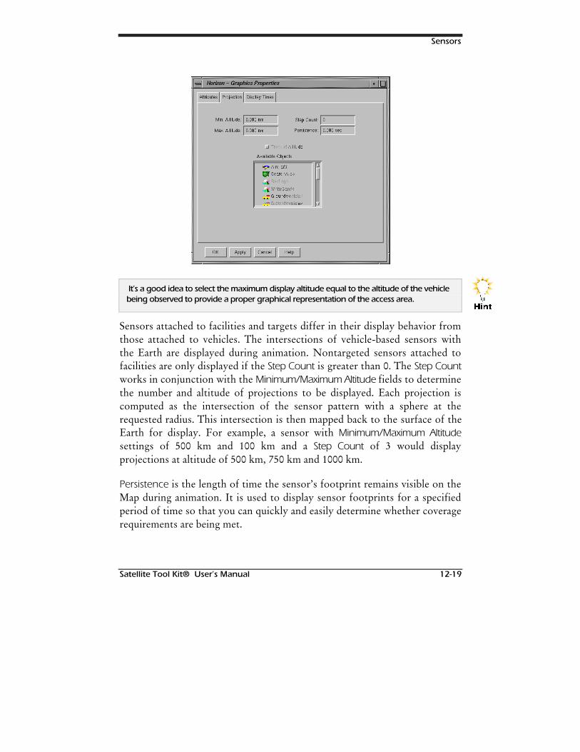
Sensors
Satellite Tool Kit® User’s Manual 12-19
It’s a good idea to select the maximum display altitude equal to the altitude of the vehiclebeing observed to provide a proper graphical representation of the access area.
Sensors attached to facilities and targets differ in their display behavior fromthose attached to vehicles. The intersections of vehicle-based sensors withthe Earth are displayed during animation. Nontargeted sensors attached tofacilities are only displayed if the Step Count is greater than 0. The Step Countworks in conjunction with the Minimum/Maximum Altitude fields to determinethe number and altitude of projections to be displayed. Each projection iscomputed as the intersection of the sensor pattern with a sphere at therequested radius. This intersection is then mapped back to the surface of theEarth for display. For example, a sensor with Minimum/Maximum Altitudesettings of 500 km and 100 km and a Step Count of 3 would displayprojections at altitude of 500 km, 750 km and 1000 km.
Persistence is the length of time the sensor’s footprint remains visible on theMap during animation. It is used to display sensor footprints for a specifiedperiod of time so that you can quickly and easily determine whether coveragerequirements are being met.
+LQW
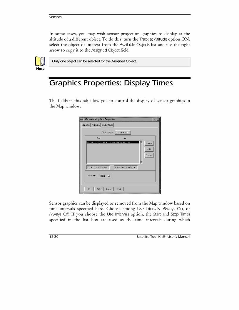
Sensors
12-20 Satellite Tool Kit® User’s Manual
In some cases, you may wish sensor projection graphics to display at thealtitude of a different object. To do this, turn the Track at Altitude option ON,select the object of interest from the Available Objects list and use the rightarrow to copy it to the Assigned Object field.
Only one object can be selected for the Assigned Object.
Graphics Properties: Display Times
The fields in this tab allow you to control the display of sensor graphics inthe Map window.
Sensor graphics can be displayed or removed from the Map window based ontime intervals specified here. Choose among Use Intervals, Always On, orAlways Off. If you choose the Use Intervals option, the Start and Stop Timesspecified in the list box are used as the time intervals during which
1RWH

Sensors
Satellite Tool Kit® User’s Manual 12-21
facility/target graphics display in the Map window. If you choose the AlwaysOn option, facility/target graphics always display in the Map window,regardless of the intervals specified in the list box. If you choose the AlwaysOff option, facility/target graphics never display in the Map window.
To specify the times during which facility/target graphics should display inthe Map window, enter the Start and Stop Times, then use the Add button. Usethe Change button to modify a time interval in the list. Use the Removebutton to remove a time period from the list.
You can also choose whether the time intervals should be “deconflicted,” ormodified so that display time periods don’t overlap. If the Deconflict field isset to Automatic, STK automatically modifies all time intervals during whichan overlap occurs so that the intervals are further segmented to avoid overlap.If the field is set to None, no changes are made to time interval overlaps. Ifthe field is set to Manual, when an overlap occurs in the time interval list, anAcknowledge window appears when you click the OK or Apply button to alertyou to the fact that the overlap exists. It is then your decision whether to setthe Deconflict field to Automatic so that the overlap is fixed, change the timeintervals yourself by modifying the appropriate entries in the list box, orignore the message and continue.
Constraints: Basic
The fields in this tab allow you to impose standard constraints for the sensor.With the exception of the Field of View constraint, the definitions of allconstraints on this tab should be taken from the parent object of the sensor.
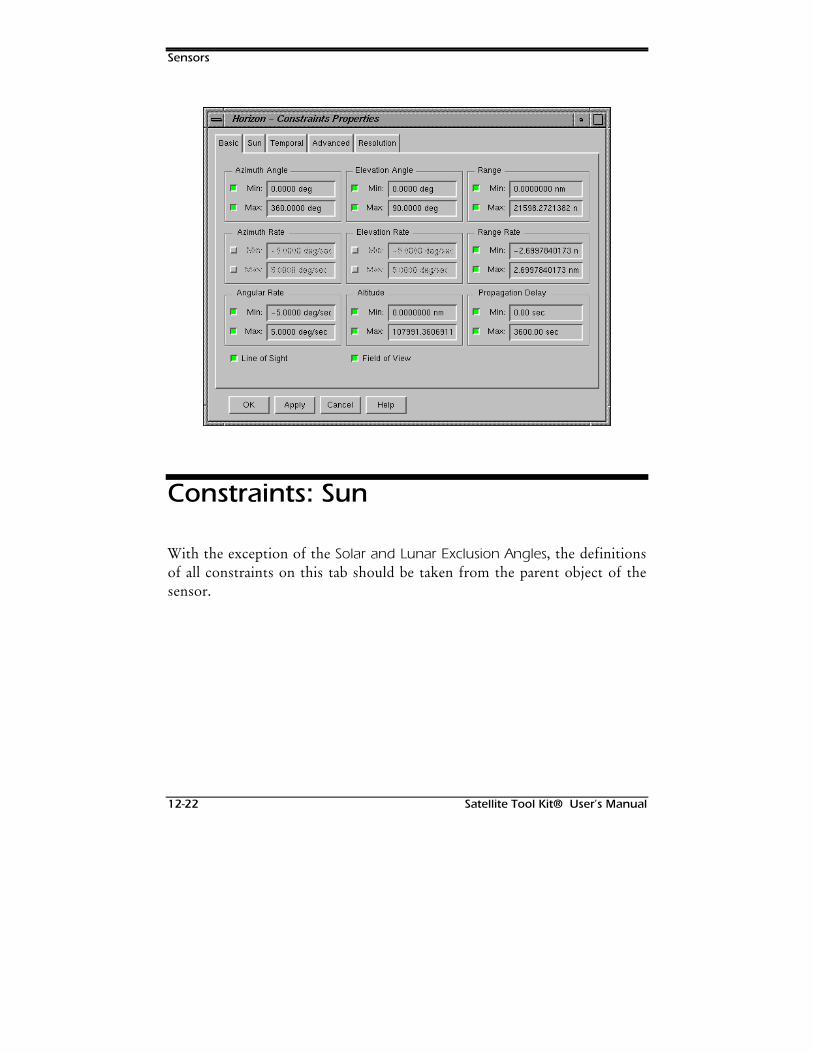
Sensors
12-22 Satellite Tool Kit® User’s Manual
Constraints: Sun
With the exception of the Solar and Lunar Exclusion Angles, the definitionsof all constraints on this tab should be taken from the parent object of thesensor.
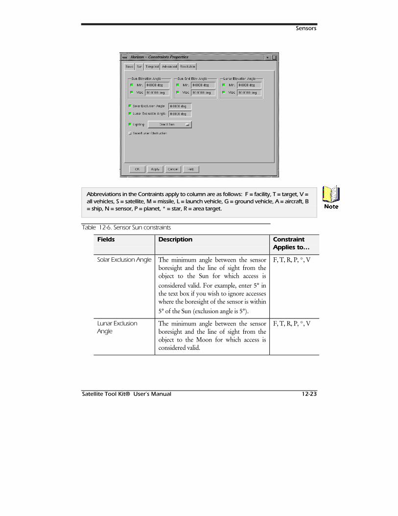
Sensors
Satellite Tool Kit® User’s Manual 12-23
Abbreviations in the Contraints apply to column are as follows: F = facility, T = target, V =all vehicles, S = satellite, M = missile, L = launch vehicle, G = ground vehicle, A = aircraft, B= ship, N = sensor, P = planet, * = star, R = area target.
Table 12-6. Sensor Sun constraints
Fields Description ConstraintApplies to…
Solar Exclusion Angle The minimum angle between the sensorboresight and the line of sight from theobject to the Sun for which access isconsidered valid. For example, enter 5° inthe text box if you wish to ignore accesseswhere the boresight of the sensor is within5° of the Sun (exclusion angle is 5°).
F, T, R, P, *, V
Lunar ExclusionAngle
The minimum angle between the sensorboresight and the line of sight from theobject to the Moon for which access isconsidered valid.
F, T, R, P, *, V
1RWH
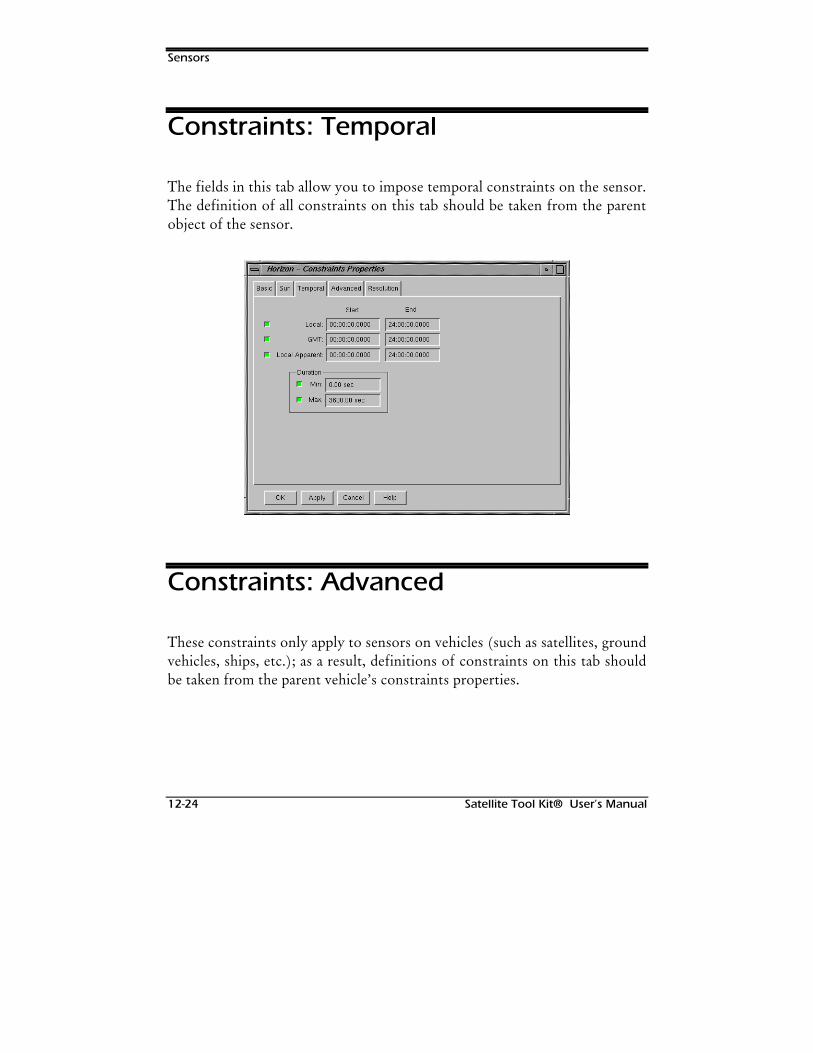
Sensors
12-24 Satellite Tool Kit® User’s Manual
Constraints: Temporal
The fields in this tab allow you to impose temporal constraints on the sensor.The definition of all constraints on this tab should be taken from the parentobject of the sensor.
Constraints: Advanced
These constraints only apply to sensors on vehicles (such as satellites, groundvehicles, ships, etc.); as a result, definitions of constraints on this tab shouldbe taken from the parent vehicle’s constraints properties.
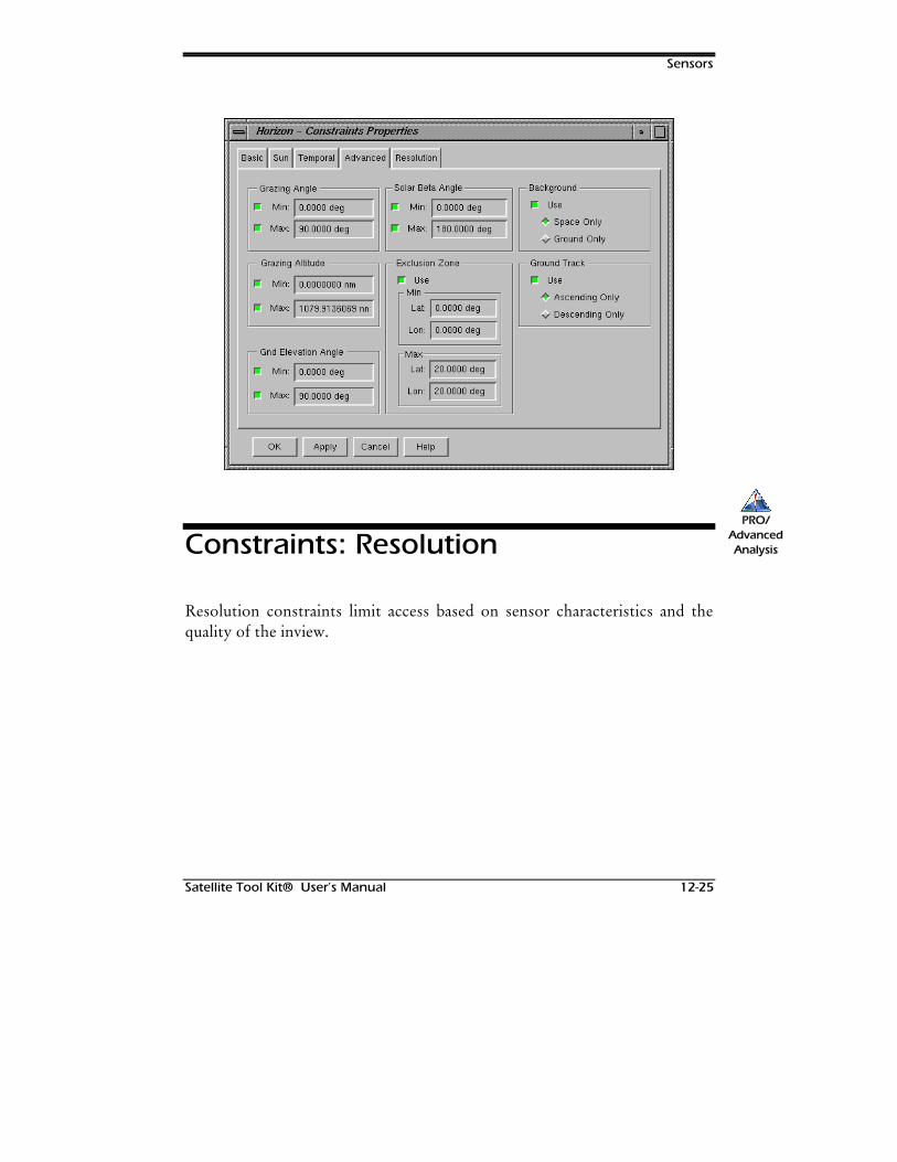
Sensors
Satellite Tool Kit® User’s Manual 12-25
Constraints: Resolution
Resolution constraints limit access based on sensor characteristics and thequality of the inview.
PRO/AdvancedAnalysis
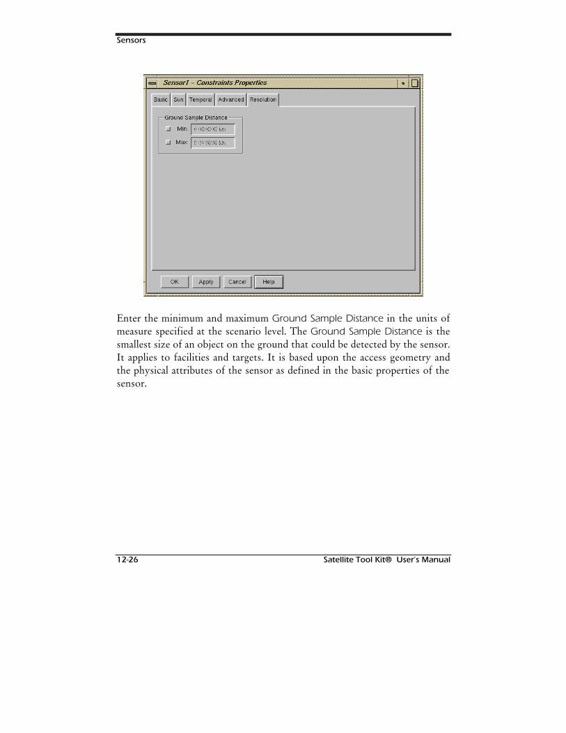
Sensors
12-26 Satellite Tool Kit® User’s Manual
Enter the minimum and maximum Ground Sample Distance in the units ofmeasure specified at the scenario level. The Ground Sample Distance is thesmallest size of an object on the ground that could be detected by the sensor.It applies to facilities and targets. It is based upon the access geometry andthe physical attributes of the sensor as defined in the basic properties of thesensor.
Satellite Tool Kit® User’s Manual 13-1
13USING STK TOOLS
Overview
To assist in satellite and systems analysis, STK offers various tools that can beused to manipulate and display the data contained in individual objects. Thesetools are separate from the properties of the object and include suchfunctions as calculating access between objects, computing lightingconditions for an object, creating reports and graphs, using the satellitedatabase to import satellites, calculating a vehicle or sensor swath, andgenerating a walker constellation. You can also remove accesses from allobjects in the scenario and show or hide the Map window.
STK tools are available through the Tools menu. Some of the tools can onlybe used for certain objects. For instance, swath can only be used for vehiclesand sensors; it is grayed out in the pull-down menu if another object isselected. For information about the objects in STK and their characteristics,please refer to the appropriate chapter in this manual.
STK tools such as reports and graphs are discussed in separate chapters dueto their complexity. Please refer to Chapter 14 for information about thefour database tools (Satellite, City, Facility and Star) available in STK,
Using STK Tools
13-2 Satellite Tool Kit® User’s Manual
Chapter 15 for Report and Graph tools, Chapter 16 for the Dynamic Displayand Strip Chart tools.
Chapter Contents
Access ........................................................................................................13-3
Calculating Access between Objects ....................................................13-3
Setting Access Graphics for the Map Window......................................13-5
Generating Access Reports ...................................................................13-6
Viewing Azimuth, Elevation and Range Data for Access ......................13-7
Using the Custom and Dynamic Display Options ................................13-8
Creating Graphs for Access Data ..........................................................13-8
Removing Accesses from the Map Window.........................................13-9
Accesses and Their Defining Objects ..................................................13-10
Lighting....................................................................................................13-11
Viewing the AER Report......................................................................13-13
Viewing a Time Data Report...............................................................13-13
Lifetime (Module) .....................................................................................13-14
Advanced ...........................................................................................13-17
Computing Lifetime ............................................................................13-19
Lifetime Results....................................................................................13-20
Report .................................................................................................13-21
Graph .................................................................................................13-22
Swath (Advanced Analysis Module).........................................................13-23
Vehicle Swath.....................................................................................13-23
Sensor Swath......................................................................................13-25
Walker Constellation ................................................................................13-26
Using STK Tools
Satellite Tool Kit® User’s Manual 13-3
Remove Accesses................................................................................13-29
Close Approach Tool (Module) ................................................................13-29
Time Period.........................................................................................13-31
Access Constraint................................................................................13-31
Search Constraint................................................................................13-32
Advanced Options..............................................................................13-32
Computing Close Approaches............................................................13-34
Export Shapefile Tool................................................................................13-35
Change Icon Tool ....................................................................................13-35
Orbit Wizard.............................................................................................13-36
Access
STK allows you to determine the times one object can “access,” or see,another object. In addition, you can impose constraints on accesses betweenobjects to define what constitutes a valid access. These constraints aredefined as properties of the objects between which accesses are beingcalculated. STK can calculate access from vehicles, facilities, targets, areatargets, and sensors to all objects (including planets and stars) within thescenario.
Calculating Access between Objects
To calculate accesses, highlight an object in the Browser window, selectAccess from the Tools menu. An Access window appears.
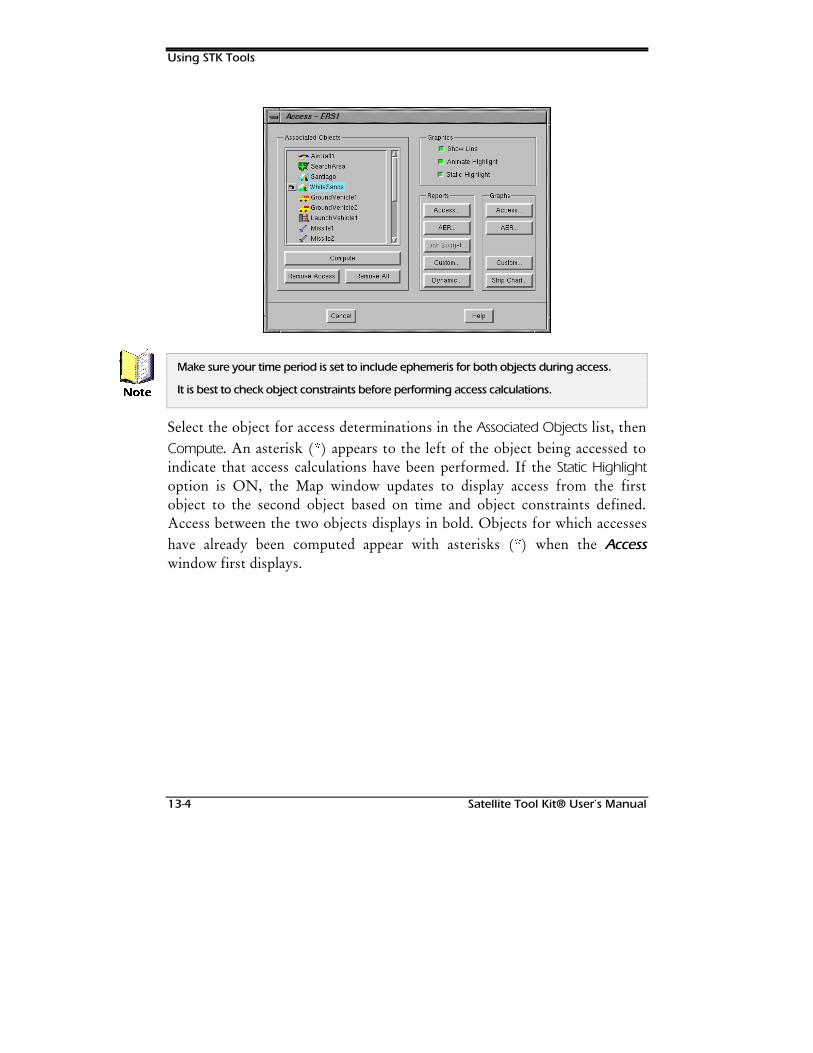
Using STK Tools
13-4 Satellite Tool Kit® User’s Manual
Make sure your time period is set to include ephemeris for both objects during access.
It is best to check object constraints before performing access calculations.
Select the object for access determinations in the Associated Objects list, thenCompute. An asterisk ( ) appears to the left of the object being accessed toindicate that access calculations have been performed. If the Static Highlightoption is ON, the Map window updates to display access from the firstobject to the second object based on time and object constraints defined.Access between the two objects displays in bold. Objects for which accesseshave already been computed appear with asterisks ( ) when the Accesswindow first displays.
1RWH
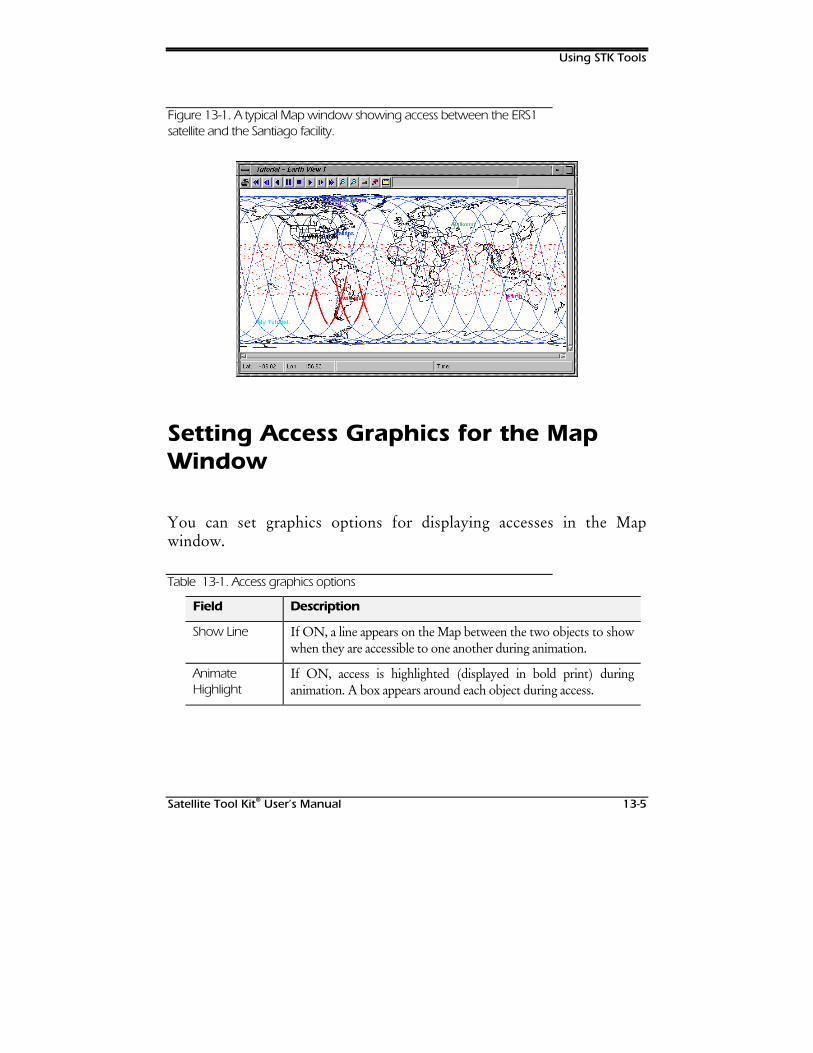
Using STK Tools
Satellite Tool Kit® User’s Manual 13-5
Figure 13-1. A typical Map window showing access between the ERS1satellite and the Santiago facility.
Setting Access Graphics for the MapWindow
You can set graphics options for displaying accesses in the Mapwindow.
Table 13-1. Access graphics options
Field Description
Show Line If ON, a line appears on the Map between the two objects to showwhen they are accessible to one another during animation.
AnimateHighlight
If ON, access is highlighted (displayed in bold print) duringanimation. A box appears around each object during access.

Using STK Tools
13-6 Satellite Tool Kit® User’s Manual
Field Description
Static Highlight If ON, access is highlighted in the Map window when the scenariois not animating. This appears as a bold line on top of the groundtrack for a vehicle or vehicle sensor and as an X for a facility, targetor attached sensor.
Generating Access Reports
Use the Access button in the Reports field to generate a report that providesaccess times between the two objects selected.
To learn more about the commands available in the Access Summary Report window,refer to Chapter 15 of this manual. STK is shipped with a number of standard report styles;you can also customize a report to meet your requirements. For more information aboutstandard reports and instructions for customizing reports, refer to Chapter 15 of thismanual.
Figure 13-2. A sample Access Report showing access data for the ERS1satellite to the Santiago facility

Using STK Tools
Satellite Tool Kit® User’s Manual 13-7
Viewing Azimuth, Elevation andRange Data for Access
Use the AER… button in the Reports field to view access data in terms ofAER.
Figure 13-3. A sample AER Report showing access data for ERS1 to theSantiago facility.
Using STK Tools
13-8 Satellite Tool Kit® User’s Manual
Azimuth and elevation values in the report are computed based on the localcoordinate system of the first object (object for which the Access window isdisplayed). Data is displayed for the periods of valid access.
Using the Custom and DynamicDisplay Options
Custom reports and dynamic data displays can be quickly generated bypressing the Custom… or Dynamic… Report buttons. These buttons displaydialogs described in Chapters 15 and 16 of this manual.
Creating Graphs for Access Data
To view access data in graph form, use the Access button the Graphs field.
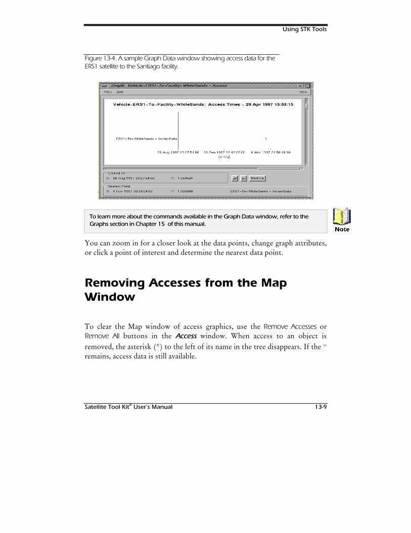
Using STK Tools
Satellite Tool Kit® User’s Manual 13-9
Figure 13-4. A sample Graph Data window showing access data for theERS1 satellite to the Santiago facility.
To learn more about the commands available in the Graph Data window, refer to theGraphs section in Chapter 15 of this manual.
You can zoom in for a closer look at the data points, change graph attributes,or click a point of interest and determine the nearest data point.
Removing Accesses from the MapWindow
To clear the Map window of access graphics, use the Remove Accesses orRemove All buttons in the Access window. When access to an object isremoved, the asterisk ( ) to the left of its name in the tree disappears. If the remains, access data is still available.
1RWH
Using STK Tools
13-10 Satellite Tool Kit® User’s Manual
Accesses and Their DefiningObjects
An access is defined by the two objects for which the access is computed.Once an access is created, it maintains a close relationship with the definingobjects. If either of the defining objects is changed in such a way that theaccess times may be altered, the access is automatically recomputed. Also, ifeither of the defining objects is removed from the scenario, the access isautomatically removed.
The term target is used here to refer to any type of object in STK, not just an instance ofthe Target class.
Access and targeted sensors have a special relationship. The “on” times forthe targeted sensor are computed based upon accesses between the sensorand its assigned targets. These “on” times are automatically updatedwhenever a targeted sensor or one of its targets are changed. The interactionbetween a targeted sensor and another object that is not a target of the sensorcan be somewhat confusing if the targeted sensor has multiple targetsassigned to it.
If a targeted sensor could access multiple targets simultaneously, a projectionof the sensor to all accessible targets would be displayed during animation.When accesses to a targeted sensor are computed, however, the pointing ofthe sensor must be uniquely defined at each point in time. To accomplishthis, STK points the sensor to each accessible target until the end of thattarget’s accessibility, starting with the first accessible target. A targetedsensor may, therefore, point toward a particular target for part or none of itsaccessible intervals, depending on the accesses to the other targets.
1RWH
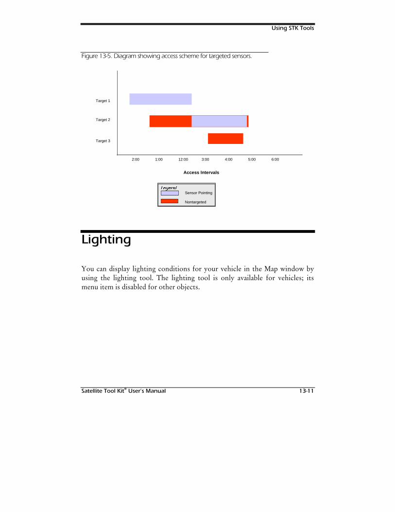
Using STK Tools
Satellite Tool Kit® User’s Manual 13-11
Figure 13-5. Diagram showing access scheme for targeted sensors.
Target 1
Target 2
Target 3
Access Intervals
2:00 1:00 12:00 3:00 4:00 5:00 6:00
/HJHQGSensor Pointing
Nontargeted
Lighting
You can display lighting conditions for your vehicle in the Map window byusing the lighting tool. The lighting tool is only available for vehicles; itsmenu item is disabled for other objects.
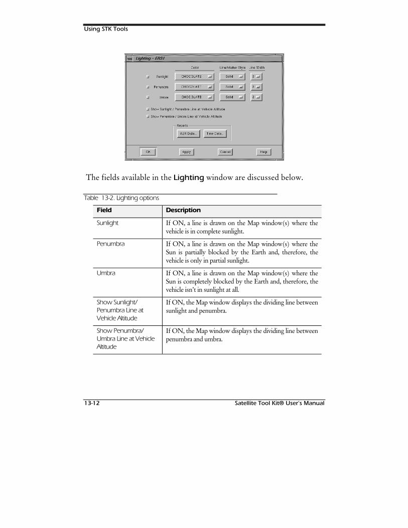
Using STK Tools
13-12 Satellite Tool Kit® User’s Manual
The fields available in the Lighting window are discussed below.
Table 13-2. Lighting options
Field Description
Sunlight If ON, a line is drawn on the Map window(s) where thevehicle is in complete sunlight.
Penumbra If ON, a line is drawn on the Map window(s) where theSun is partially blocked by the Earth and, therefore, thevehicle is only in partial sunlight.
Umbra If ON, a line is drawn on the Map window(s) where theSun is completely blocked by the Earth and, therefore, thevehicle isn’t in sunlight at all.
Show Sunlight/Penumbra Line atVehicle Altitude
If ON, the Map window displays the dividing line betweensunlight and penumbra.
Show Penumbra/Umbra Line at VehicleAltitude
If ON, the Map window displays the dividing line betweenpenumbra and umbra.
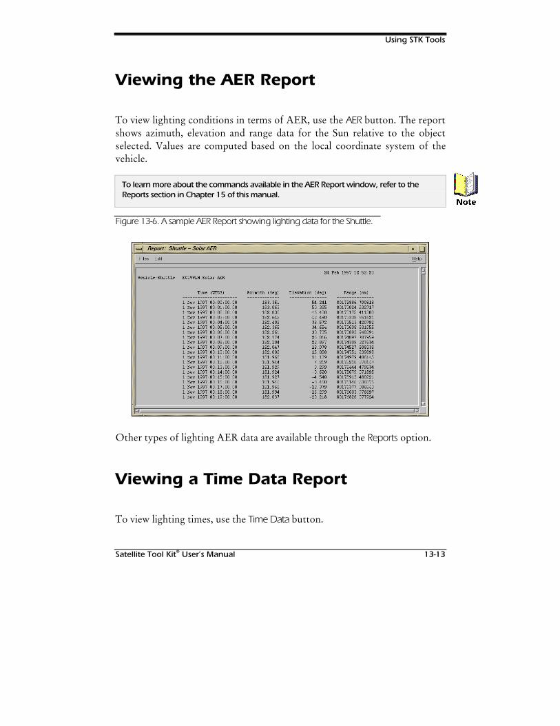
Using STK Tools
Satellite Tool Kit® User’s Manual 13-13
Viewing the AER Report
To view lighting conditions in terms of AER, use the AER button. The reportshows azimuth, elevation and range data for the Sun relative to the objectselected. Values are computed based on the local coordinate system of thevehicle.
To learn more about the commands available in the AER Report window, refer to theReports section in Chapter 15 of this manual.
Figure 13-6. A sample AER Report showing lighting data for the Shuttle.
Other types of lighting AER data are available through the Reports option.
Viewing a Time Data Report
To view lighting times, use the Time Data button.
1RWH
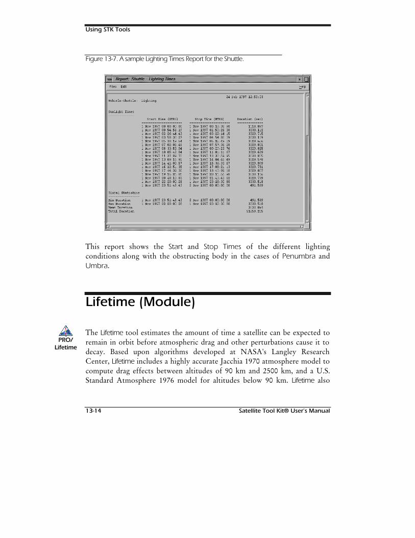
Using STK Tools
13-14 Satellite Tool Kit® User’s Manual
Figure 13-7. A sample Lighting Times Report for the Shuttle.
This report shows the Start and Stop Times of the different lightingconditions along with the obstructing body in the cases of Penumbra andUmbra.
Lifetime (Module)
The Lifetime tool estimates the amount of time a satellite can be expected toremain in orbit before atmospheric drag and other perturbations cause it todecay. Based upon algorithms developed at NASA's Langley ResearchCenter, Lifetime includes a highly accurate Jacchia 1970 atmosphere model tocompute drag effects between altitudes of 90 km and 2500 km, and a U.S.Standard Atmosphere 1976 model for altitudes below 90 km. Lifetime also
PRO/PRO/LifetimeLifetime
Using STK Tools
Satellite Tool Kit® User’s Manual 13-15
uses a simplified Earth gravitational model to enhance performance andprovide quicker results. Since the inclusion of higher order terms doesn'tsignificantly impact orbit decay estimates, the gravity model only considersoblateness effects through J5. Lifetime also models the effects of solar andlunar gravity and solar radiation pressure when computing perturbations tothe orbit.
Lifetime estimates the decay date of the satellite, the total lifetime from thesatellite's epoch and the number of orbits completed by the time of decay.The orbital elements over the life of the satellite can also be shown in graphand report formats.
Within Lifetime, only long-term changes to the satellite's orbit are considered;short-period variations are assumed to average out and, therefore, aren’tincluded in the calculations. As a result, Lifetime isn’t well suited for theinvestigation of the short-term behavior of satellite orbits or perturbations tothe orbital elements over a single revolution. A satellite's orbit is allowed todecay due to atmospheric and gravitational perturbations, with noconsideration given to propulsive thrust or changes in attitude that couldresult in the addition of energy to the orbit.
Lifetime is currently limited to the analysis of Earth-orbiting satellites. Although there is noupper limit to the altitude of a satellite that can be analyzed by Lifetime, the calculationsmay not be sensitive enough to decay a satellite with a perigee altitude greater than 2500km.
User inputs include the satellite's physical characteristics—mass, area, anddrag and reflection coefficients. In addition, solar flux and planetarygeomagnetic index information must also be supplied.
1RWH
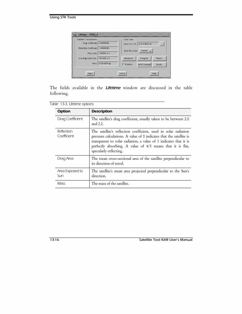
Using STK Tools
13-16 Satellite Tool Kit® User’s Manual
The fields available in the Lifetime window are discussed in the tablefollowing.
Table 13-3. Lifetime options
Option Description
Drag Coefficient The satellite's drag coefficient, usually taken to be between 2.0and 2.2.
ReflectionCoefficient
The satellite's reflection coefficient, used in solar radiationpressure calculations. A value of 0 indicates that the satellite istransparent to solar radiation, a value of 1 indicates that it isperfectly absorbing. A value of 4/3 means that it is flat,specularly reflecting.
Drag Area The mean cross-sectional area of the satellite perpendicular toits direction of travel.
Area Exposed toSun
The satellite's mean area projected perpendicular to the Sun'sdirection.
Mass The mass of the satellite.
Using STK Tools
Satellite Tool Kit® User’s Manual 13-17
Option Description
Solar Data An ASCII file containing predicted values of the monthly mean10.7 cm solar radiation flux (F10.7) and geomagnetic index (Ap).Refer to Appendix C for the format of this file.
Use the Solar Flux Data field to specify whether you want touse Nominal (50th percentile) or +2σ (97.7th percentile) solarflux and geomagnetic index data. Nominal flux predictionsrepresent an average case (longer lifetime); +2σ values representthe worst case (shorter lifetime).
Graphics If ON, the satellite’s final orbit displays in the Map window.The ground track spans the length of the last orbit and is notintended to represent the exact point of decay.
SGP4 Compute The SGP4 theory estimates a satellite's orbital lifetime based onUSSPACECOM SGP4 general perturbations theory. It usesthe satellite's 2-line mean elements and, as such, doesn’t requireany of the inputs in either of Lifetime or Lifetime Advancedwindows. As a purely analytical solution, it doesn’t providetime-histories of the orbital elements suitable for reports andgraphs. Use the SGP4 Compute button to compute the lifetimebased on this theory.
Advanced
Use the Advanced button to define the speed and accuracy of the calculationsto be performed when estimating a satellite’s orbital lifetime.
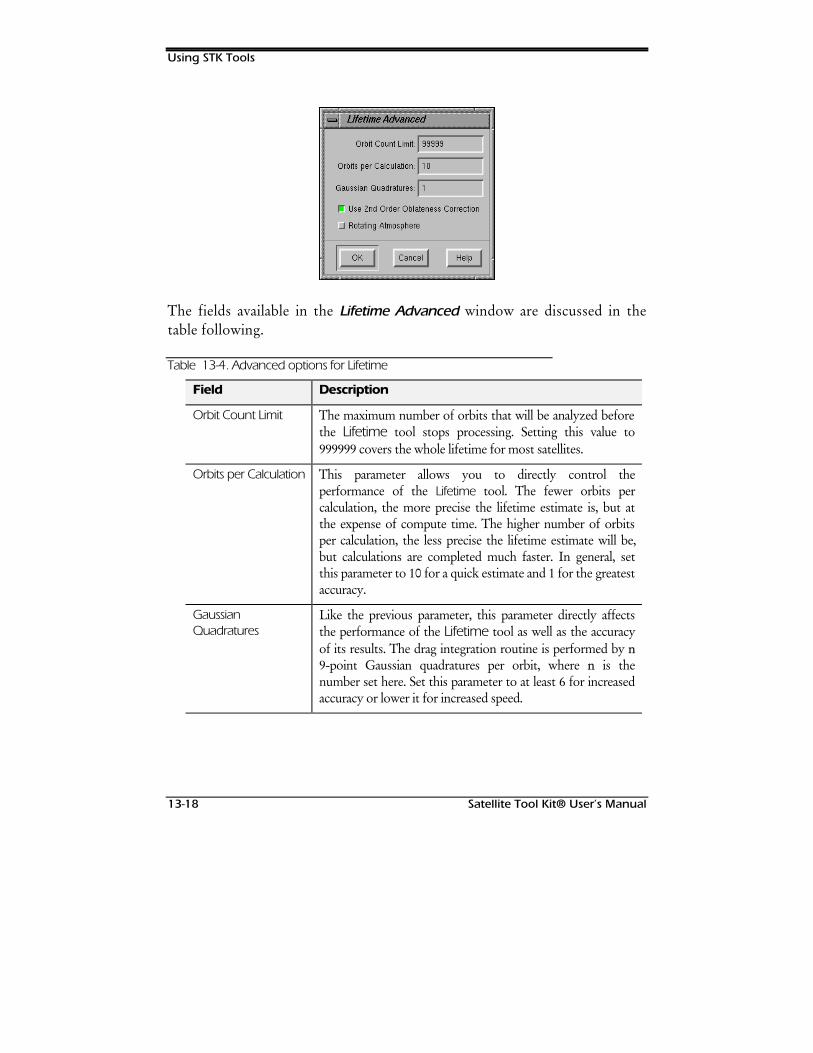
Using STK Tools
13-18 Satellite Tool Kit® User’s Manual
The fields available in the Lifetime Advanced window are discussed in thetable following.
Table 13-4. Advanced options for Lifetime
Field Description
Orbit Count Limit The maximum number of orbits that will be analyzed beforethe Lifetime tool stops processing. Setting this value to999999 covers the whole lifetime for most satellites.
Orbits per Calculation This parameter allows you to directly control theperformance of the Lifetime tool. The fewer orbits percalculation, the more precise the lifetime estimate is, but atthe expense of compute time. The higher number of orbitsper calculation, the less precise the lifetime estimate will be,but calculations are completed much faster. In general, setthis parameter to 10 for a quick estimate and 1 for the greatestaccuracy.
GaussianQuadratures
Like the previous parameter, this parameter directly affectsthe performance of the Lifetime tool as well as the accuracyof its results. The drag integration routine is performed by nn9-point Gaussian quadratures per orbit, where nn is thenumber set here. Set this parameter to at least 6 for increasedaccuracy or lower it for increased speed.
Using STK Tools
Satellite Tool Kit® User’s Manual 13-19
Field Description
Use 2nd OrderOblatenessCorrection
If ON, a second-order correction is included in the Earth
oblateness calculation. This correction is the J22 term, which
contributes as much to the gravitational potential as the J3, J4,and J5 terms do.
Rotating Atmosphere If ON, the west-to-east winds induced by atmosphericrotation are included in the perturbations to the orbit.
Computing Lifetime
Once the appropriate values have been set in the Lifetime and Advancedwindows, use the Compute button to start the lifetime calculations. Howlong the Lifetime tool takes to estimate the satellite's lifetime dependsprimarily on how high the satellite is at epoch and on the Orbits perCalculation and Gaussian Quadratures parameters. A Progress window showsthe progress of the Lifetime tool and gives you the opportunity to cancel thecomputations if necessary. The slider bar reaches 100% when the satellitedecays. The "percent of limit" progress message reaches 100% when thenumber of orbits analyzed by Lifetime equals the Orbit Count Limit parameterset in the Advanced window. If the "percent of limit" rapidly andsignificantly outpaces the slider bar, you may want to cancel thecomputations and increase the Orbit Count Limit. Otherwise, Lifetime willprobably reach the limit before the satellite actually decays.
Similarly, if the slider bar moves very slowly or if the time remaining steadily rises,Lifetime may take a while to estimate the orbital lifetime of the satellite.
Using STK Tools
13-20 Satellite Tool Kit® User’s Manual
For MSGP4 satellites, the orbital lifetime can be estimated by either the primary orbitlifetime theory or the SGP4 analytical theory. The SGP4 theory estimates a satellite's orbitallifetime based on USSPACECOM SGP4 general perturbations theory. It uses the satellite's 2-line mean elements and, as such, doesn’t require any of the inputs in either of Lifetime orLifetime Advanced windows. As a purely analytical solution, it doesn’t provide time-histories of the orbital elements suitable for reports and graphs. Use the SGP4 Computebutton to compute the lifetime based on this theory.
If you want a quick estimate, cancel the calculations and adjust the Orbits PerCalculation and/or Gaussian Quadratures fields in the Advanced window. Since theintegration of atmospheric drag effects is computationally expensive, reducing thenumber of Gaussian Quadratures noticeably increases Lifetime's speed. Someaccuracy will be lost, but the difference in total lifetime for near- Earth satellitesshould be small.
Increasing the Orbits Per Calculation parameter can also significantly increaseLifetime's speed. When the number of Orbits per Calculation is greater than one,Lifetime assumes that the perturbations to the satellite's orbit remain constant over thenumber of orbits specified.
The Lifetime tool runs until either the satellite decays or the Orbit Count Limit isreached. A satellite is assumed to decay when its height of perigee drops below 64 km.
Lifetime Results
As stated earlier, the Lifetime tool estimates the orbital lifetime of a satellite andprovides the corresponding date of decay. It should be emphasized that although theLifetime computations are based on sophisticated orbital theory and accurateenvironment models, the result is still an estimate. Due to the seemingly random 10%variation in atmospheric density and because of the difficulty in accurately predictingsolar activity, satellite lifetimes can’t be determined with an accuracy better than+10% of the actual lifetime. Furthermore, assumptions and simplifications made inorder to produce a practical computer implementation of the lifetime theoryintroduce an additional degree of uncertainty in the final result. The Lifetime tool is
1RWH
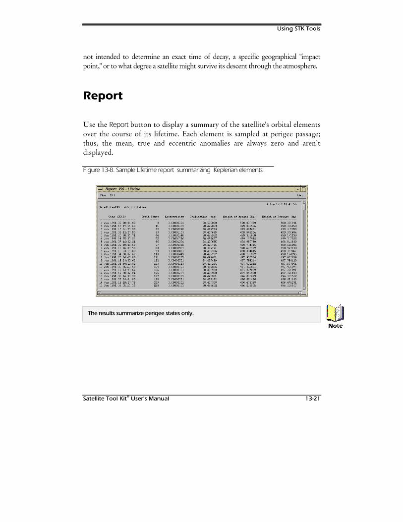
Using STK Tools
Satellite Tool Kit® User’s Manual 13-21
not intended to determine an exact time of decay, a specific geographical "impactpoint," or to what degree a satellite might survive its descent through the atmosphere.
Report
Use the Report button to display a summary of the satellite's orbital elementsover the course of its lifetime. Each element is sampled at perigee passage;thus, the mean, true and eccentric anomalies are always zero and aren’tdisplayed.
Figure 13-8. Sample Lifetime report summarizing Keplerian elements
The results summarize perigee states only.
1RWH
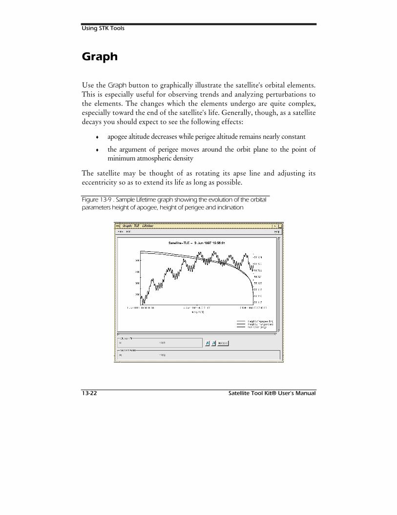
Using STK Tools
13-22 Satellite Tool Kit® User’s Manual
Graph
Use the Graph button to graphically illustrate the satellite's orbital elements.This is especially useful for observing trends and analyzing perturbations tothe elements. The changes which the elements undergo are quite complex,especially toward the end of the satellite's life. Generally, though, as a satellitedecays you should expect to see the following effects:
♦ apogee altitude decreases while perigee altitude remains nearly constant
♦ the argument of perigee moves around the orbit plane to the point ofminimum atmospheric density
The satellite may be thought of as rotating its apse line and adjusting itseccentricity so as to extend its life as long as possible.
Figure 13-9 . Sample Lifetime graph showing the evolution of the orbitalparameters height of apogee, height of perigee and inclination
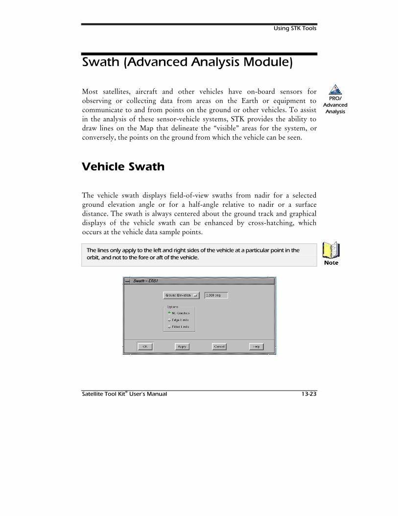
Using STK Tools
Satellite Tool Kit® User’s Manual 13-23
Swath (Advanced Analysis Module)
Most satellites, aircraft and other vehicles have on-board sensors forobserving or collecting data from areas on the Earth or equipment tocommunicate to and from points on the ground or other vehicles. To assistin the analysis of these sensor-vehicle systems, STK provides the ability todraw lines on the Map that delineate the “visible” areas for the system, orconversely, the points on the ground from which the vehicle can be seen.
Vehicle Swath
The vehicle swath displays field-of-view swaths from nadir for a selectedground elevation angle or for a half-angle relative to nadir or a surfacedistance. The swath is always centered about the ground track and graphicaldisplays of the vehicle swath can be enhanced by cross-hatching, whichoccurs at the vehicle data sample points.
The lines only apply to the left and right sides of the vehicle at a particular point in theorbit, and not to the fore or aft of the vehicle.
PRO/AdvancedAnalysis
1RWH
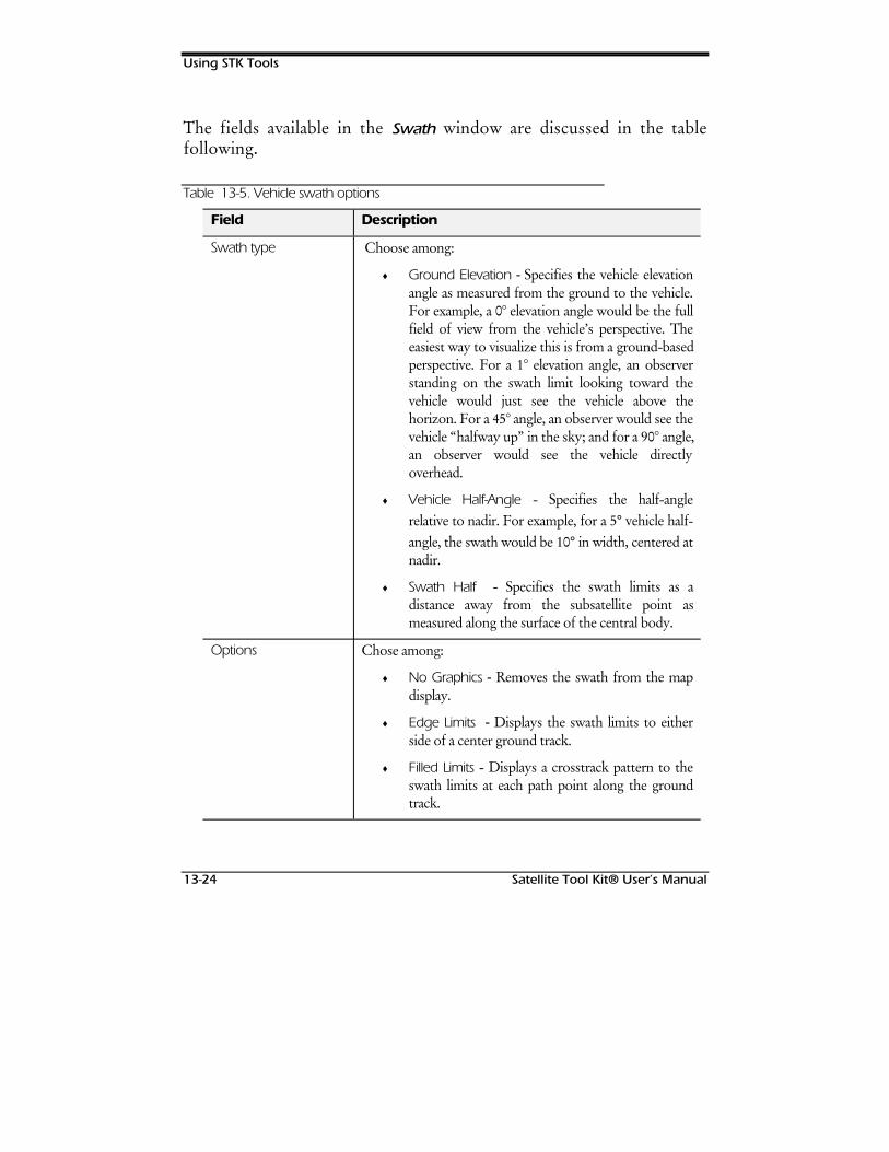
Using STK Tools
13-24 Satellite Tool Kit® User’s Manual
The fields available in the Swath window are discussed in the tablefollowing.
Table 13-5. Vehicle swath options
Field Description
Swath type Choose among:
♦ Ground Elevation - Specifies the vehicle elevationangle as measured from the ground to the vehicle.For example, a 0° elevation angle would be the fullfield of view from the vehicle’s perspective. Theeasiest way to visualize this is from a ground-basedperspective. For a 1° elevation angle, an observerstanding on the swath limit looking toward thevehicle would just see the vehicle above thehorizon. For a 45° angle, an observer would see thevehicle “halfway up” in the sky; and for a 90° angle,an observer would see the vehicle directlyoverhead.
♦ Vehicle Half-Angle - Specifies the half-anglerelative to nadir. For example, for a 5° vehicle half-angle, the swath would be 10° in width, centered atnadir.
♦ Swath Half - Specifies the swath limits as adistance away from the subsatellite point asmeasured along the surface of the central body.
Options Chose among:
♦ No Graphics - Removes the swath from the mapdisplay.
♦ Edge Limits - Displays the swath limits to eitherside of a center ground track.
♦ Filled Limits - Displays a crosstrack pattern to theswath limits at each path point along the groundtrack.
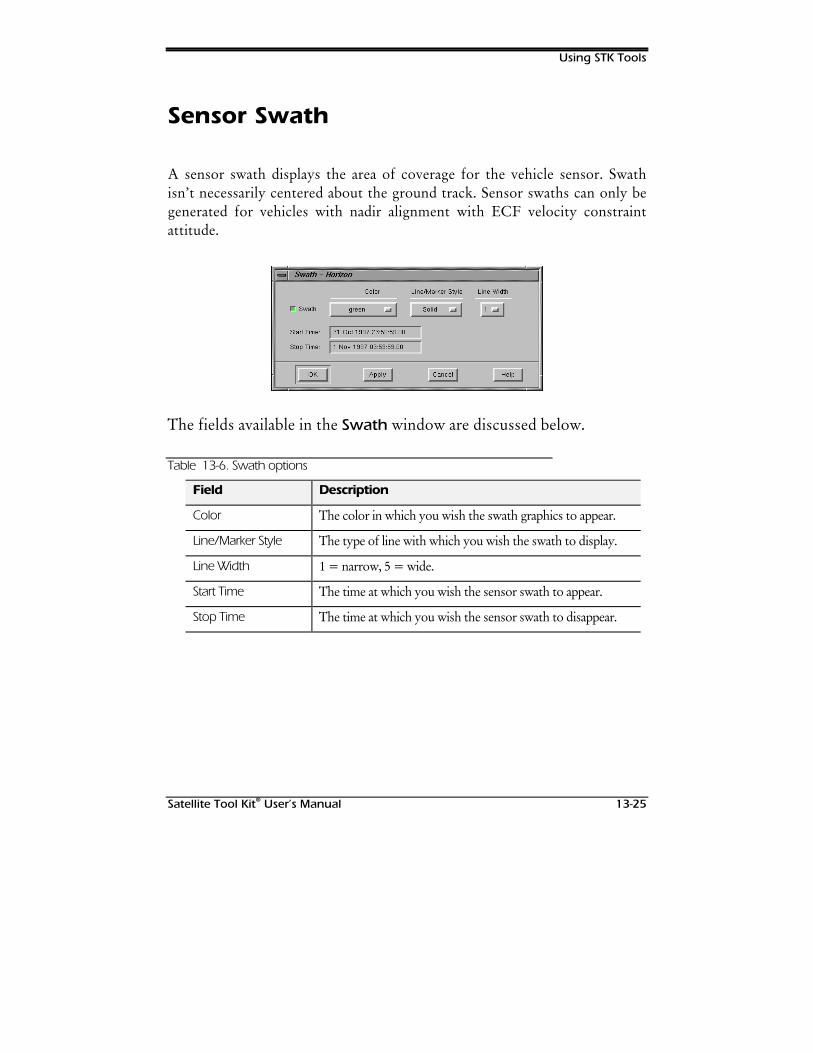
Using STK Tools
Satellite Tool Kit® User’s Manual 13-25
Sensor Swath
A sensor swath displays the area of coverage for the vehicle sensor. Swathisn’t necessarily centered about the ground track. Sensor swaths can only begenerated for vehicles with nadir alignment with ECF velocity constraintattitude.
The fields available in the Swath window are discussed below.
Table 13-6. Swath options
Field Description
Color The color in which you wish the swath graphics to appear.
Line/Marker Style The type of line with which you wish the swath to display.
Line Width 1 = narrow, 5 = wide.
Start Time The time at which you wish the sensor swath to appear.
Stop Time The time at which you wish the sensor swath to disappear.
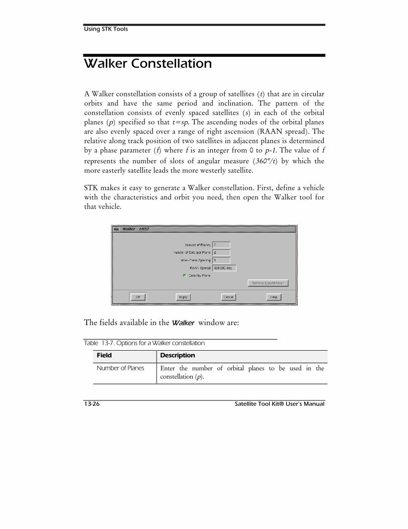
Using STK Tools
13-26 Satellite Tool Kit® User’s Manual
Walker Constellation
A Walker constellation consists of a group of satellites (t) that are in circularorbits and have the same period and inclination. The pattern of theconstellation consists of evenly spaced satellites (s) in each of the orbitalplanes (p) specified so that t=sp. The ascending nodes of the orbital planesare also evenly spaced over a range of right ascension (RAAN spread). Therelative along track position of two satellites in adjacent planes is determinedby a phase parameter (f) where f is an integer from 0 to p-1. The value of frepresents the number of slots of angular measure (360°/t) by which themore easterly satellite leads the more westerly satellite.
STK makes it easy to generate a Walker constellation. First, define a vehiclewith the characteristics and orbit you need, then open the Walker tool forthat vehicle.
The fields available in the Walker window are:
Table 13-7. Options for a Walker constellation
Field Description
Number of Planes Enter the number of orbital planes to be used in theconstellation (p).
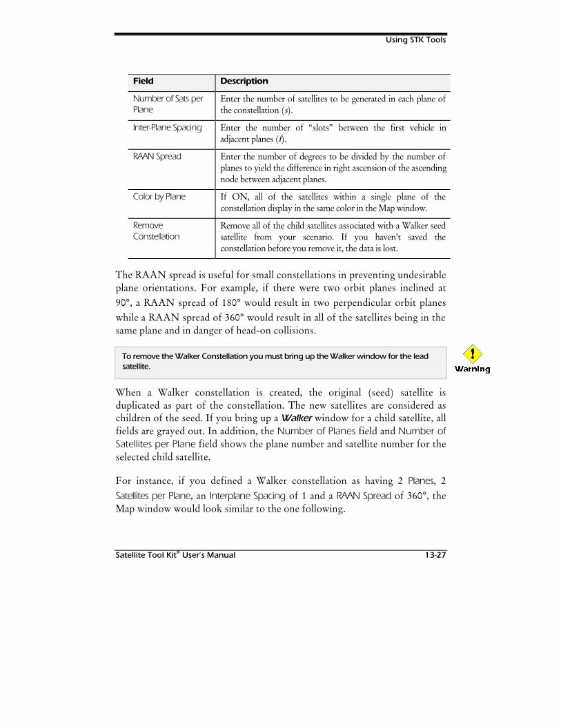
Using STK Tools
Satellite Tool Kit® User’s Manual 13-27
Field Description
Number of Sats perPlane
Enter the number of satellites to be generated in each plane ofthe constellation (s).
Inter-Plane Spacing Enter the number of “slots” between the first vehicle inadjacent planes (f).
RAAN Spread Enter the number of degrees to be divided by the number ofplanes to yield the difference in right ascension of the ascendingnode between adjacent planes.
Color by Plane If ON, all of the satellites within a single plane of theconstellation display in the same color in the Map window.
RemoveConstellation
Remove all of the child satellites associated with a Walker seedsatellite from your scenario. If you haven’t saved theconstellation before you remove it, the data is lost.
The RAAN spread is useful for small constellations in preventing undesirableplane orientations. For example, if there were two orbit planes inclined at90°, a RAAN spread of 180° would result in two perpendicular orbit planeswhile a RAAN spread of 360° would result in all of the satellites being in thesame plane and in danger of head-on collisions.
To remove the Walker Constellation you must bring up the Walker window for the leadsatellite.
When a Walker constellation is created, the original (seed) satellite isduplicated as part of the constellation. The new satellites are considered aschildren of the seed. If you bring up a Walker window for a child satellite, allfields are grayed out. In addition, the Number of Planes field and Number ofSatellites per Plane field shows the plane number and satellite number for theselected child satellite.
For instance, if you defined a Walker constellation as having 2 Planes, 2Satellites per Plane, an Interplane Spacing of 1 and a RAAN Spread of 360°, theMap window would look similar to the one following.
:DUQLQJ
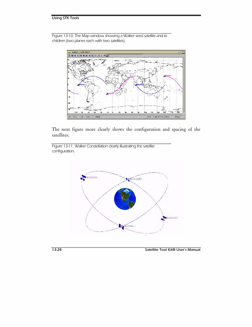
Using STK Tools
13-28 Satellite Tool Kit® User’s Manual
Figure 13-10. The Map window showing a Walker seed satellite and itschildren (two planes each with two satellites).
The next figure more clearly shows the configuration and spacing of thesatellites.
Figure 13-11. Walker Constellation clearly illustrating the satelliteconfiguration.
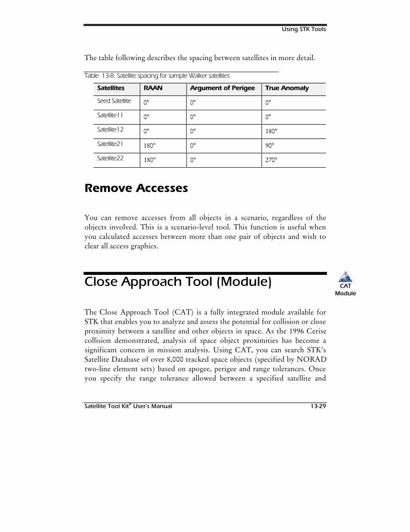
Using STK Tools
Satellite Tool Kit® User’s Manual 13-29
The table following describes the spacing between satellites in more detail.
Table 13-8. Satellite spacing for sample Walker satellites
Satellites RAAN Argument of Perigee True Anomaly
Seed Satellite 0° 0° 0°
Satellite11 0° 0° 0°
Satellite12 0° 0° 180°
Satellite21 180° 0° 90°
Satellite22 180° 0° 270°
Remove Accesses
You can remove accesses from all objects in a scenario, regardless of theobjects involved. This is a scenario-level tool. This function is useful whenyou calculated accesses between more than one pair of objects and wish toclear all access graphics.
Close Approach Tool (Module)
The Close Approach Tool (CAT) is a fully integrated module available forSTK that enables you to analyze and assess the potential for collision or closeproximity between a satellite and other objects in space. As the 1996 Cerisecollision demonstrated, analysis of space object proximities has become asignificant concern in mission analysis. Using CAT, you can search STK’sSatellite Database of over 8,000 tracked space objects (specified by NORADtwo-line element sets) based on apogee, perigee and range tolerances. Onceyou specify the range tolerance allowed between a specified satellite and
CATCATModuleModule
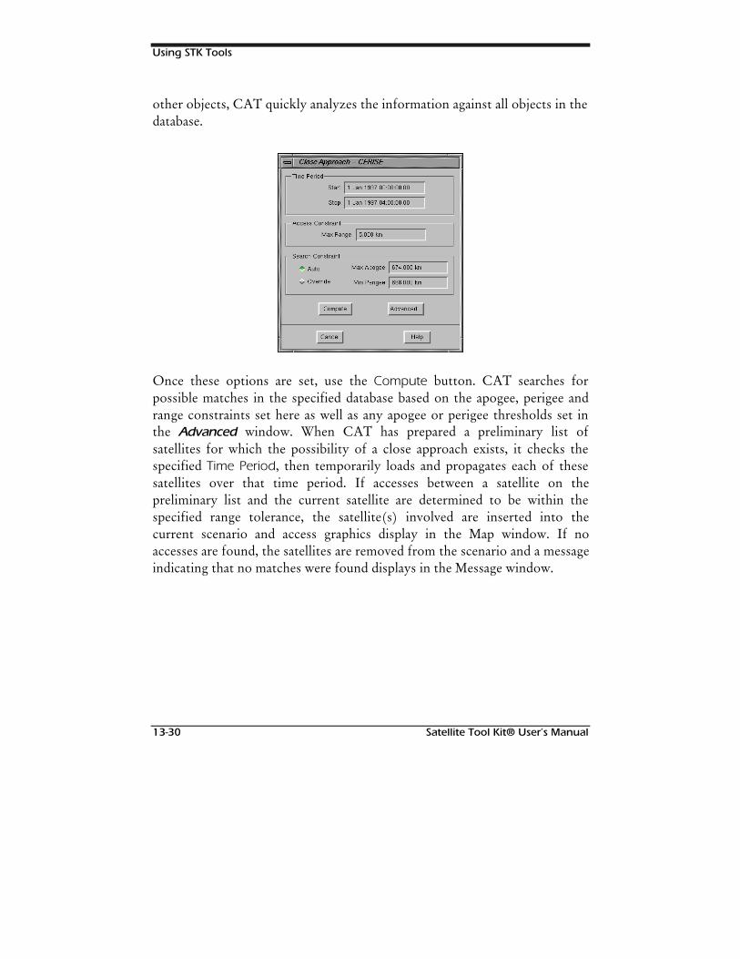
Using STK Tools
13-30 Satellite Tool Kit® User’s Manual
other objects, CAT quickly analyzes the information against all objects in thedatabase.
Once these options are set, use the Compute button. CAT searches forpossible matches in the specified database based on the apogee, perigee andrange constraints set here as well as any apogee or perigee thresholds set inthe Advanced window. When CAT has prepared a preliminary list ofsatellites for which the possibility of a close approach exists, it checks thespecified Time Period, then temporarily loads and propagates each of thesesatellites over that time period. If accesses between a satellite on thepreliminary list and the current satellite are determined to be within thespecified range tolerance, the satellite(s) involved are inserted into thecurrent scenario and access graphics display in the Map window. If noaccesses are found, the satellites are removed from the scenario and a messageindicating that no matches were found displays in the Message window.
Using STK Tools
Satellite Tool Kit® User’s Manual 13-31
Time Period
By default, the ephemeris start and stop time periods are entered in the Startand Stop Time fields. You can change these values if necessary. If you enteran incremental Start and Stop Time within the approved time period for thesatellite, then change the Start Time to a value that exceeds the current StopTime, the Stop Time is updated in the same increment as previously entered.For example, if the Start Time is 1 Jan 1997 00:00:00.00 and the Stop Timeis 1 Jan 1997 01:00:00.00 and you change the Start Time to be 1 Jan 199702:00:00.00, CAT automatically changes the Stop Time to be 1 Jan 199703:00:00.00. If the Stop Time would be outside of the satellite’s Time Period,CAT automatically adjusts the Stop Time to match the Stop Time of thesatellite.
You can’t set a Start or Stop Time outside of those set for the satellite’s ephemeris in thesatellite’s Basic Properties window. If you attempt to do so, an error message displays andthe changes are discarded.
Access Constraint
In the Max Range field, enter the maximum allowable distance between thecurrent object and any other object in the database. During analysis, whenCAT finds an object that is within the range specified in this field, the objectand the associated time is flagged and displayed. The Max Range Constraint isautomatically set for the satellite.
:DUQLQJ

Using STK Tools
13-32 Satellite Tool Kit® User’s Manual
Search Constraint
If you choose Auto, the Max Apogee and Min Perigee values areautomatically updated whenever the Time Period changes based on thesatellite’s minimum and maximum altitude for the time period. If you chooseOverride, the Max Apogee and Min Perigee values are used, regardless of theTime Period specified. These values are used to develop a preliminary list ofpossible objects from the specified database that pass close to or through thesatellite’s orbit.
Advanced Options
Use the Advanced… button to specify the satellite database to be searchedand to set other limitations and graphics display parameters.
By default, CAT searches the stkAllTLE satellite database. To change thedatabase, enter the new database name and path in the File Name field.
Using STK Tools
Satellite Tool Kit® User’s Manual 13-33
Search Tolerances
Because the apogee and perigee values of satellites included in the varioussatellite database change over time, the Apogee and Perigee Threshold fieldsare used to determine a valid range (plus or minus) for these values. TheApogee value used in the search is equal to:
Search Apogee = A + AT + R
where A is apogee, AT is the apogee threshold and R is the range constraint.
The Perigee value used in the search is equal to:
Search Perigee = P - PT - R
where P is perigee, PT is the perigee threshold and R is the range constraint.For instance, if you enter a value of 1000.0 km for both Apogee and Perigeein the Close Approach window, then enter a value of 1.0 km for the Apogeeand Perigee Thresholds in the Close Approach Advanced window, CATwould search for apogee and perigee values in the satellite database within +1.0 km of the original satellite’s apogee and perigee value. Any RangeConstraint would be added to the total for the apogee and subtracted for theperigee.
Launch Window
The Start and Stop Times for the time during which the satellite may belaunched can be specified in the Launch Window field. For these parametersto be meaningful, the satellite should be defined using an external ephemerisfile that includes the satellite’s ascent profile.
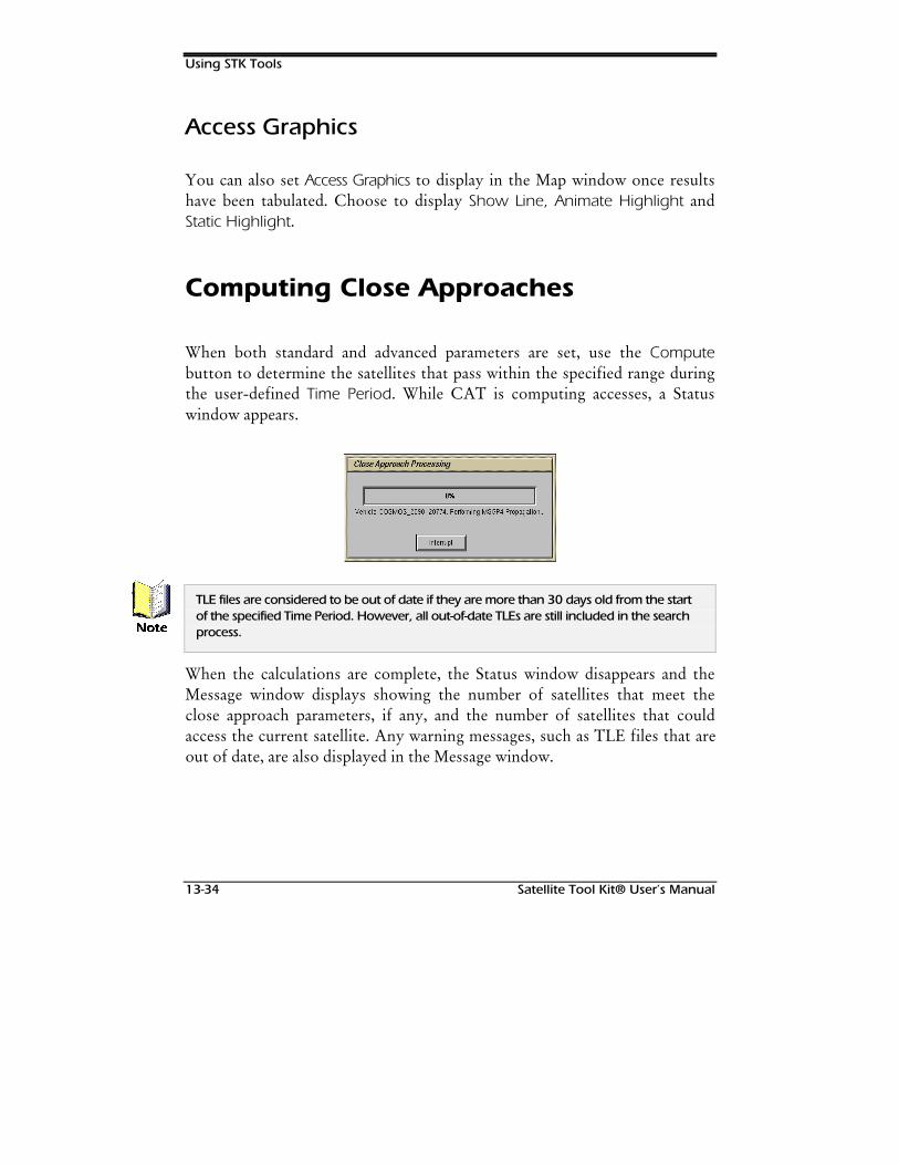
Using STK Tools
13-34 Satellite Tool Kit® User’s Manual
Access Graphics
You can also set Access Graphics to display in the Map window once resultshave been tabulated. Choose to display Show Line, Animate Highlight andStatic Highlight.
Computing Close Approaches
When both standard and advanced parameters are set, use the Computebutton to determine the satellites that pass within the specified range duringthe user-defined Time Period. While CAT is computing accesses, a Statuswindow appears.
TLE files are considered to be out of date if they are more than 30 days old from the startof the specified Time Period. However, all out-of-date TLEs are still included in the searchprocess.
When the calculations are complete, the Status window disappears and theMessage window displays showing the number of satellites that meet theclose approach parameters, if any, and the number of satellites that couldaccess the current satellite. Any warning messages, such as TLE files that areout of date, are also displayed in the Message window.
1RWH
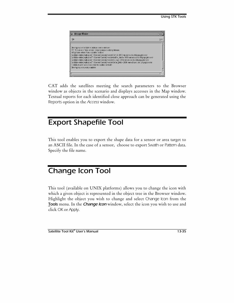
Using STK Tools
Satellite Tool Kit® User’s Manual 13-35
CAT adds the satellites meeting the search parameters to the Browserwindow as objects in the scenario and displays accesses in the Map window.Textual reports for each identified close approach can be generated using theReports option in the Access window.
Export Shapefile Tool
This tool enables you to export the shape data for a sensor or area target toan ASCII file. In the case of a sensor, choose to export Swath or Pattern data.Specify the file name.
Change Icon Tool
This tool (available on UNIX platforms) allows you to change the icon withwhich a given object is represented in the object tree in the Browser window.Highlight the object you wish to change and select Change Icon from theTools menu. In the Change Icon window, select the icon you wish to use andclick OK or Apply.
Using STK Tools
13-36 Satellite Tool Kit® User’s Manual
Orbit Wizard
If you create a satellite in STK, an Orbit Wizard appears. The Wizard isdesigned to assit you in creating any one of six standard orbits:
♦ Sun Synchronous - Orbit is designed to pass overhead at the same localtime each revolution.
♦ GeoStationary - Orbit is designed to remain over one point on theground.
♦ Repeating Ground Trace - Orbit is designed to provide a repeatingground coverage cycle.
♦ Molniya - A highly elliptical orbit that is useful for communications overthe Northern hemisphere.
♦ Critically Inclined - Orbit is maintained at a fixed latitude.
♦ Critically Incclined Sun Synchronous - Orbit is maintained at a fixedlatitude and passes overhead at the same local time each revolution.
Once you’ve chosen the type of orbit youwish to create, the Wizard promptsyou to define the orbital parameters for the satellite. These parameters canthen be updated as needed in the Orbit tab.
Satellite Tool Kit® User’s Manual 14-1
14CITY, FACILITY,
SATELLITE & STARDATABASES
Overview
STK provides several tools that assist you in generating facilities, satellites,targets and stars quickly and easily. Several comprehensive databases areshipped with STK for your use. These databases include information aboutthousands of facilities, cities, satellites and stars. Using the databases, you caneasily identify an object and insert it into the current scenario.
Chapter Contents
City Database.............................................................................................14-2
Querying a Database............................................................................14-3

City, Facility, Satellite & Star Databases
14-2 Satellite Tool Kit® User’s Manual
Viewing Search Results .........................................................................14-4
Object Description................................................................................14-5
Facility Database ........................................................................................14-5
Querying a Database............................................................................14-6
Viewing Search Results .........................................................................14-7
Object Description................................................................................14-8
Satellite Database .......................................................................................14-8
Querying a Database..........................................................................14-10
Viewing Search Results .......................................................................14-11
Online Update....................................................................................14-12
Object Description..............................................................................14-14
Star Database...........................................................................................14-14
Querying a Database..........................................................................14-15
Viewing Search Results .......................................................................14-17
Object Description..............................................................................14-17
Load TLE ..................................................................................................14-18
Loading a Satellite TLE.........................................................................14-18
Loading a Facility TLE..........................................................................14-20
Object Description..............................................................................14-22
City Database
Use the City Database tool to identify and insert cities as facilities or targets.The city database contains thousands of cities around the world. Individualcity information includes exact location, population, etc.
PRO/AdvancedAnalysis
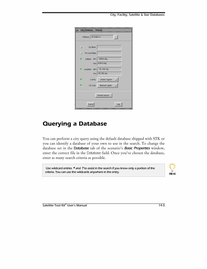
City, Facility, Satellite & Star Databases
Satellite Tool Kit® User’s Manual 14-3
Querying a Database
You can perform a city query using the default database shipped with STK oryou can identify a database of your own to use in the search. To change thedatabase set in the Database tab of the scenario’s Basic Properties window,enter the correct file in the Database field. Once you’ve chosen the database,enter as many search criteria as possible.
Use wildcard entries * and ? to assist in the search if you know only a portion of thecriteria. You can use the wildcards anywhere in the entry.
+LQW
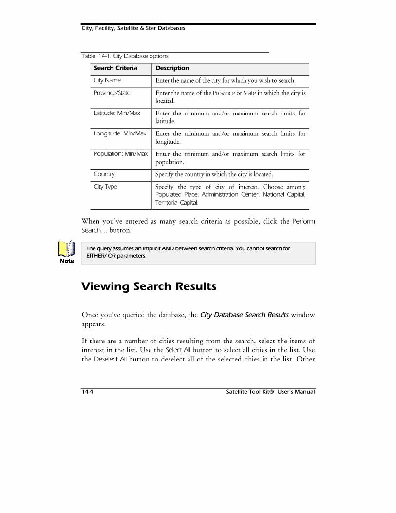
City, Facility, Satellite & Star Databases
14-4 Satellite Tool Kit® User’s Manual
Table 14-1. City Database options
Search Criteria Description
City Name Enter the name of the city for which you wish to search.
Province/State Enter the name of the Province or State in which the city islocated.
Latitude: Min/Max Enter the minimum and/or maximum search limits forlatitude.
Longitude: Min/Max Enter the minimum and/or maximum search limits forlongitude.
Population: Min/Max Enter the minimum and/or maximum search limits forpopulation.
Country Specify the country in which the city is located.
City Type Specify the type of city of interest. Choose among:Populated Place, Administration Center, National Capital,Territorial Capital.
When you’ve entered as many search criteria as possible, click the PerformSearch… button.
The query assumes an implicit AND between search criteria. You cannot search forEITHER/ OR parameters.
Viewing Search Results
Once you’ve queried the database, the City Database Search Results windowappears.
If there are a number of cities resulting from the search, select the items ofinterest in the list. Use the Select All button to select all cities in the list. Usethe Deselect All button to deselect all of the selected cities in the list. Other
1RWH
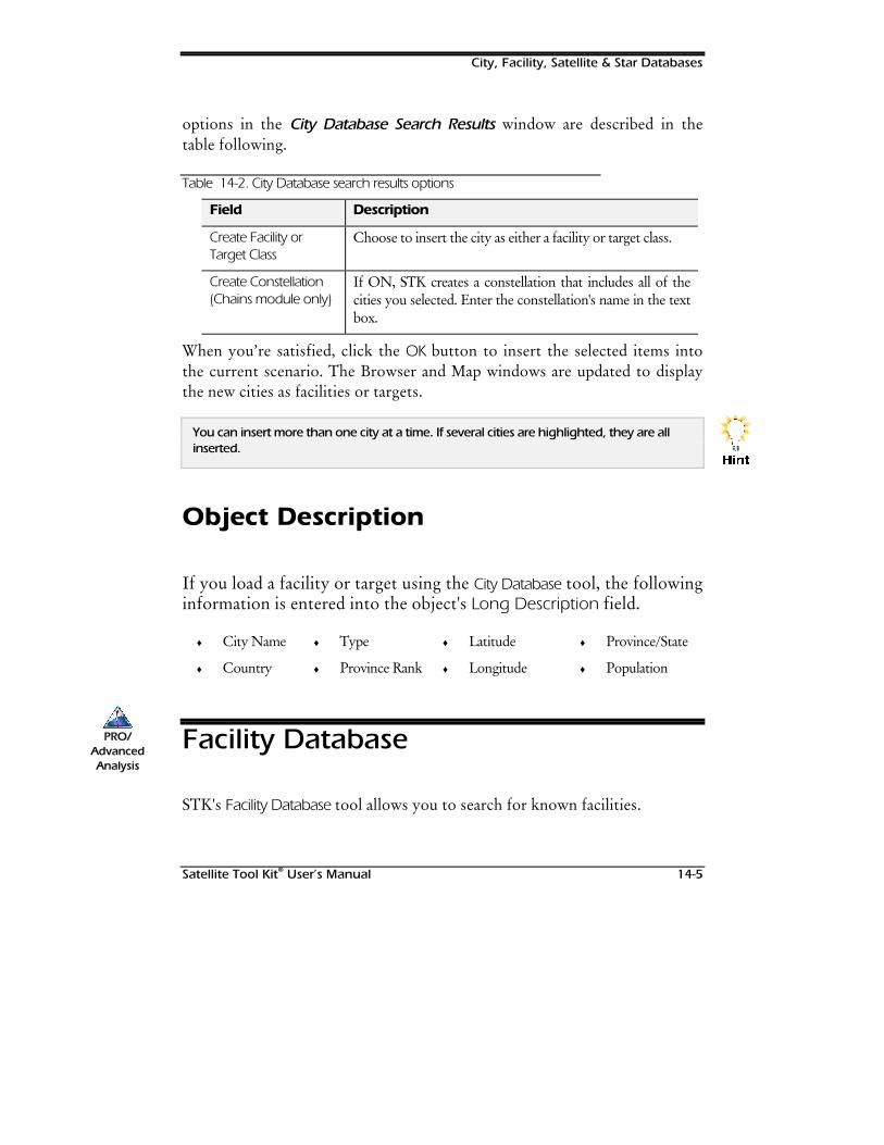
City, Facility, Satellite & Star Databases
Satellite Tool Kit® User’s Manual 14-5
options in the City Database Search Results window are described in thetable following.
Table 14-2. City Database search results options
Field Description
Create Facility orTarget Class
Choose to insert the city as either a facility or target class.
Create Constellation(Chains module only)
If ON, STK creates a constellation that includes all of thecities you selected. Enter the constellation's name in the textbox.
When you’re satisfied, click the OK button to insert the selected items intothe current scenario. The Browser and Map windows are updated to displaythe new cities as facilities or targets.
You can insert more than one city at a time. If several cities are highlighted, they are allinserted.
Object Description
If you load a facility or target using the City Database tool, the followinginformation is entered into the object's Long Description field.
♦ City Name ♦ Type ♦ Latitude ♦ Province/State
♦ Country ♦ Province Rank ♦ Longitude ♦ Population
Facility Database
STK's Facility Database tool allows you to search for known facilities.
+LQW
PRO/AdvancedAnalysis
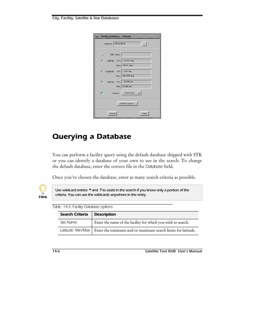
City, Facility, Satellite & Star Databases
14-6 Satellite Tool Kit® User’s Manual
Querying a Database
You can perform a facility query using the default database shipped with STKor you can identify a database of your own to use in the search. To changethe default database, enter the correct file in the Database field.
Once you’ve chosen the database, enter as many search criteria as possible.
Use wildcard entries * and ? to assist in the search if you know only a portion of thecriteria. You can use the wildcards anywhere in the entry.
Table 14-3. Facility Database options
Search Criteria Description
Site Name Enter the name of the facility for which you wish to search.
Latitude: Min/Max Enter the minimum and/or maximum search limits for latitude.
+LQW
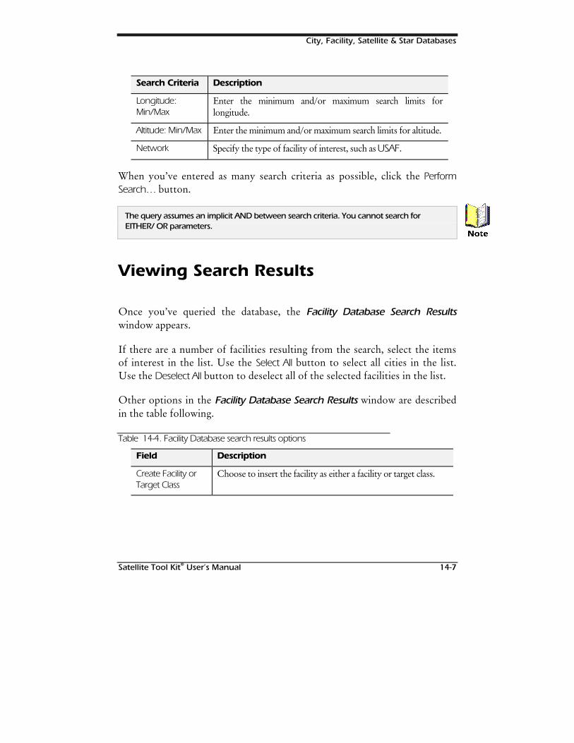
City, Facility, Satellite & Star Databases
Satellite Tool Kit® User’s Manual 14-7
Search Criteria Description
Longitude:Min/Max
Enter the minimum and/or maximum search limits forlongitude.
Altitude: Min/Max Enter the minimum and/or maximum search limits for altitude.
Network Specify the type of facility of interest, such as USAF.
When you’ve entered as many search criteria as possible, click the PerformSearch… button.
The query assumes an implicit AND between search criteria. You cannot search forEITHER/ OR parameters.
Viewing Search Results
Once you’ve queried the database, the Facility Database Search Resultswindow appears.
If there are a number of facilities resulting from the search, select the itemsof interest in the list. Use the Select All button to select all cities in the list.Use the Deselect All button to deselect all of the selected facilities in the list.
Other options in the Facility Database Search Results window are describedin the table following.
Table 14-4. Facility Database search results options
Field Description
Create Facility orTarget Class
Choose to insert the facility as either a facility or target class.
1RWH
City, Facility, Satellite & Star Databases
14-8 Satellite Tool Kit® User’s Manual
Field Description
CreateConstellation(Chains moduleonly)
If ON, STK creates a constellation that includes all of thefacility you selected. Enter the constellation's name in the textbox.
When you’re satisfied, click the OK button to insert the selected items intothe current scenario. The Browser and Map windows are updated to displaythe new facilities or targets.
You can insert more than one facility at a time. If several facilities are highlighted, they areall inserted.
Object Description
If you load a facility or target using the Facility Database tool, thefollowing information is entered into the object's Long Descriptionfield.
♦ Site Name ♦ Network
♦ Latitude ♦ East Longitude
♦ Altitude
Satellite Database
The U.S. Space Command (USSPACECOM) currently keeps track of morethan 7000 orbiting objects. USSPACECOM continuously generates datadescribing the orbits of these objects and makes it available through a varietyof sources. The data is in a form known as two-line element sets (TLE); each
+LQW
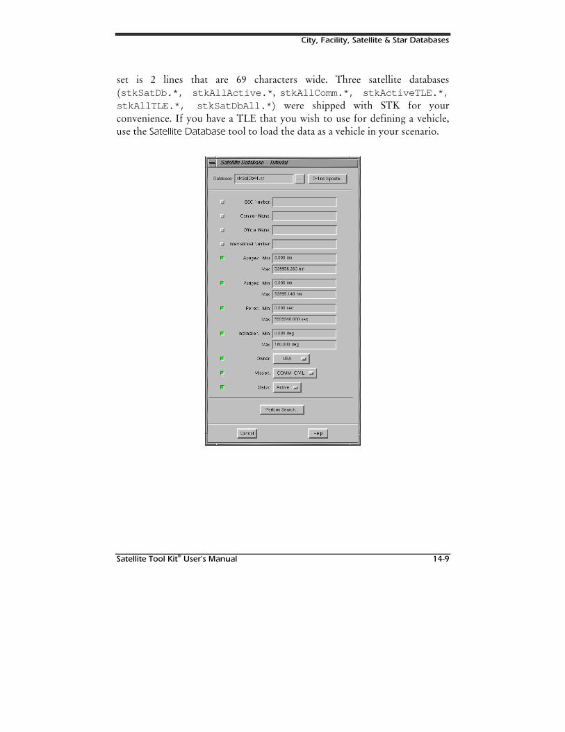
City, Facility, Satellite & Star Databases
Satellite Tool Kit® User’s Manual 14-9
set is 2 lines that are 69 characters wide. Three satellite databases(stkSatDb.*, stkAllActive.* , stkAllComm.*, stkActiveTLE.*,stkAllTLE.*, stkSatDbAll.* ) were shipped with STK for yourconvenience. If you have a TLE that you wish to use for defining a vehicle,use the Satellite Database tool to load the data as a vehicle in your scenario.
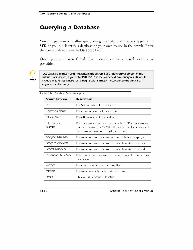
City, Facility, Satellite & Star Databases
14-10 Satellite Tool Kit® User’s Manual
Querying a Database
You can perform a satellite query using the default database shipped withSTK or you can identify a database of your own to use in the search. Enterthe correct file name in the Database field.
Once you’ve chosen the database, enter as many search criteria aspossible.
Use wildcard entries * and ? to assist in the search if you know only a portion of thecriteria. For instance, if you enter INTELSAT* in the Name text box, query results wouldinclude all satellites whose name begins with INTELSAT. You can use the wildcardsanywhere in the entry.
Table 14-5. Satellite Database options
Search Criteria Description
SSC The SSC number of the vehicle.
Common Name The common name of the satellite.
Official Name The official name of the satellite
InternationalNumber
The international number of the vehicle. The internationalnumber format is YYYY-DDD and an alpha indicator ifthere is more than one part of the satellite.
Apogee: Min/Max The minimum and/or maximum search limits for apogee.
Perigee: Min/Max The minimum and/or maximum search limits for perigee.
Period: Min/Max The minimum and/or maximum search limits for period.
Inclination: Min/Max The minimum and/or maximum search limits forinclination.
Owner The country which owns the satellite.
Mission The mission which the satellite performs.
Status Choose either Active or Inactive.
+LQW
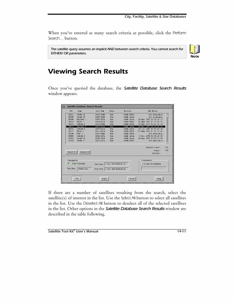
City, Facility, Satellite & Star Databases
Satellite Tool Kit® User’s Manual 14-11
When you’ve entered as many search criteria as possible, click the PerformSearch… button.
The satellite query assumes an implicit AND between search criteria. You cannot search forEITHER/ OR parameters.
Viewing Search Results
Once you’ve queried the database, the Satellite Database Search Resultswindow appears.
If there are a number of satellites resulting from the search, select thesatellite(s) of interest in the list. Use the Select All button to select all satellitesin the list. Use the Deselect All button to deselect all of the selected satellitesin the list. Other options in the Satellite Database Search Results window aredescribed in the table following.
1RWH
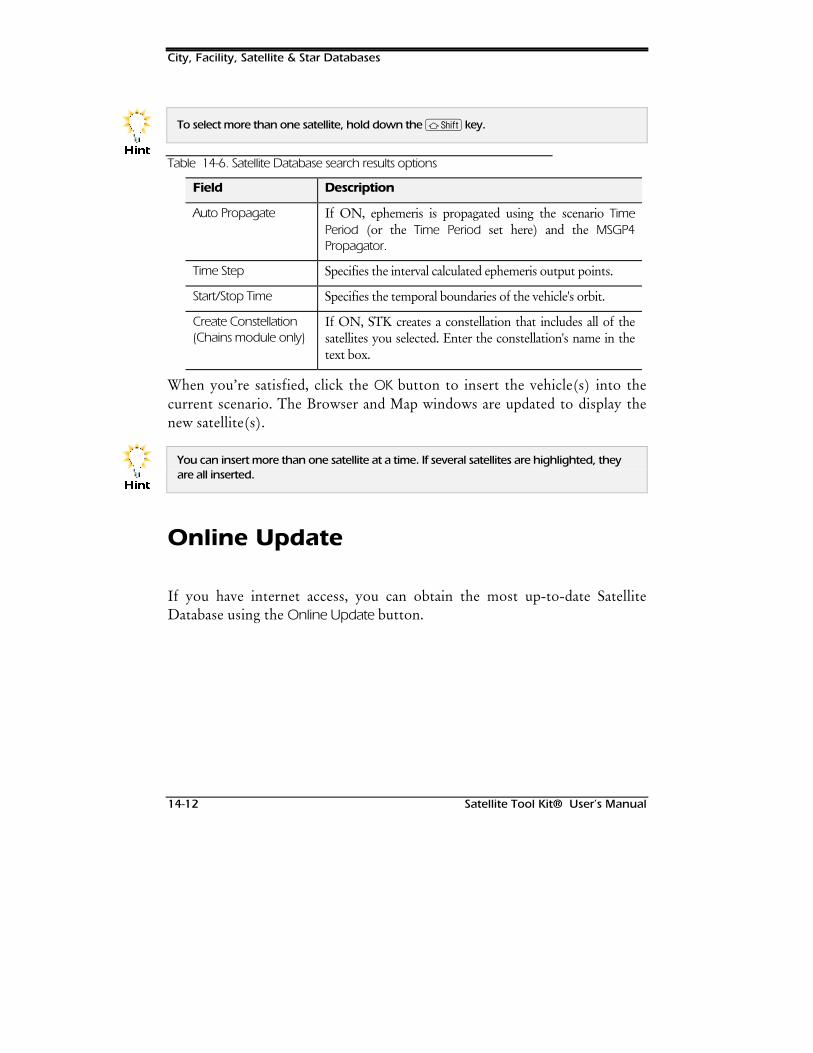
City, Facility, Satellite & Star Databases
14-12 Satellite Tool Kit® User’s Manual
To select more than one satellite, hold down the S key.
Table 14-6. Satellite Database search results options
Field Description
Auto Propagate If ON, ephemeris is propagated using the scenario TimePeriod (or the Time Period set here) and the MSGP4Propagator.
Time Step Specifies the interval calculated ephemeris output points.
Start/Stop Time Specifies the temporal boundaries of the vehicle's orbit.
Create Constellation(Chains module only)
If ON, STK creates a constellation that includes all of thesatellites you selected. Enter the constellation's name in thetext box.
When you’re satisfied, click the OK button to insert the vehicle(s) into thecurrent scenario. The Browser and Map windows are updated to display thenew satellite(s).
You can insert more than one satellite at a time. If several satellites are highlighted, theyare all inserted.
Online Update
If you have internet access, you can obtain the most up-to-date SatelliteDatabase using the Online Update button.
+LQW
+LQW
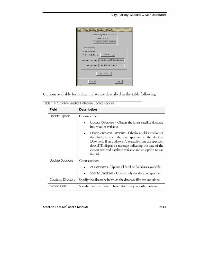
City, Facility, Satellite & Star Databases
Satellite Tool Kit® User’s Manual 14-13
Options available for online update are described in the table following
Table 14-7. Online Satellite Database update options
Field Description
Update Option Choose either:
♦ Update Database - Obtain the latest satellite databaseinformation available.
♦ Obtain Archived Database - Obtain an older version ofthe database from the date specified in the ArchiveDate field. If an update isn't available from the specifieddate, STK displays a message indicating the date of theclosest archived database available and an option to usethat file.
Update Database Choose either:
♦ All Databases - Update all Satellite Databases available.
♦ Specific Database - Update only the database specified.
Database Directory Specify the directory in which the database files are contained.
Archive Date Specify the date of the archived database you wish to obtain.
City, Facility, Satellite & Star Databases
14-14 Satellite Tool Kit® User’s Manual
When you finish, use the Go Online button to immediately begindownloading the latest information.
Object Description
If you load a satellite using the Satellite Database tool, the followinginformation is entered into the vehicle’s Long Description field.
♦ SSC Number ♦ Common Name ♦ Official Name
♦ International Number ♦ Owner ♦ Mission
♦ Launch Site ♦ Launch Date ♦ Launch Time
♦ Deorbit Date ♦ Launch Sequence ♦ Mass
♦ Apogee ♦ Perigee ♦ Period
♦ Inclination ♦ Status ♦ Write Up
Star Database
The Star Database tool allows you to identify and insert specific stars into thecurrent scenario. It contains tens of thousands of stars along withinformation about star catalog numbers, magnitude, proper motion andparallax.
PRO/AdvancedAnalysis
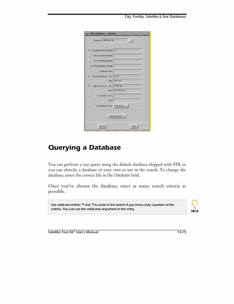
City, Facility, Satellite & Star Databases
Satellite Tool Kit® User’s Manual 14-15
Querying a Database
You can perform a star query using the default database shipped with STK oryou can identify a database of your own to use in the search. To change thedatabase, enter the correct file in the Database field.
Once you’ve chosen the database, enter as many search criteria aspossible.
Use wildcard entries * and ? to assist in the search if you know only a portion of thecriteria. You can use the wildcards anywhere in the entry.
+LQW
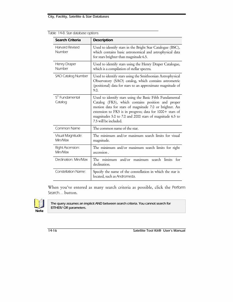
City, Facility, Satellite & Star Databases
14-16 Satellite Tool Kit® User’s Manual
Table 14-8. Star database options
Search Criteria Description
Harvard RevisedNumber
Used to identify stars in the Bright Star Catalogue (BSC),which contains basic astronomical and astrophysical datafor stars brighter than magnitude 6.5.
Henry DraperNumber
Used to identify stars using the Henry Draper Catalogue,which is a compilation of stellar spectra.
SAO Catalog Number Used to identify stars using the Smithsonian AstrophysicalObservatory (SAO) catalog, which contains astrometric(positional) data for stars to an approximate magnitude of9.0.
5th FundamentalCatalog
Used to identify stars using the Basic Fifth FundamentalCatalog (FK5), which contains position and propermotion data for stars of magnitude 7.0 or brighter. Anextension to FK5 is in progress; data for 1000+ stars ofmagnitudes 5.0 to 7.0 and 2000 stars of magnitude 6.5 to7.5 will be included.
Common Name The common name of the star.
Visual Magnitude:Min/Max
The minimum and/or maximum search limits for visualmagnitude.
Right Ascension:Min/Max
The minimum and/or maximum search limits for rightascension .
Declination: Min/Max The minimum and/or maximum search limits fordeclination.
Constellation Name: Specify the name of the constellation in which the star islocated, such as Andromeda.
When you’ve entered as many search criteria as possible, click the PerformSearch… button.
The query assumes an implicit AND between search criteria. You cannot search forEITHER/ OR parameters.
1RWH
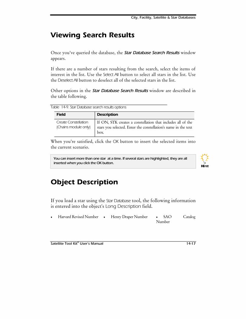
City, Facility, Satellite & Star Databases
Satellite Tool Kit® User’s Manual 14-17
Viewing Search Results
Once you’ve queried the database, the Star Database Search Results windowappears.
If there are a number of stars resulting from the search, select the items ofinterest in the list. Use the Select All button to select all stars in the list. Usethe Deselect All button to deselect all of the selected stars in the list.
Other options in the Star Database Search Results window are described inthe table following.
Table 14-9. Star Database search results options
Field Description
Create Constellation(Chains module only)
If ON, STK creates a constellation that includes all of thestars you selected. Enter the constellation's name in the textbox.
When you’re satisfied, click the OK button to insert the selected items intothe current scenario.
You can insert more than one star at a time. If several stars are highlighted, they are allinserted when you click the OK button.
Object Description
If you load a star using the Star Database tool, the following informationis entered into the object's Long Description field.
♦ Harvard Revised Number ♦ Henry Draper Number ♦ SAO CatalogNumber
+LQW
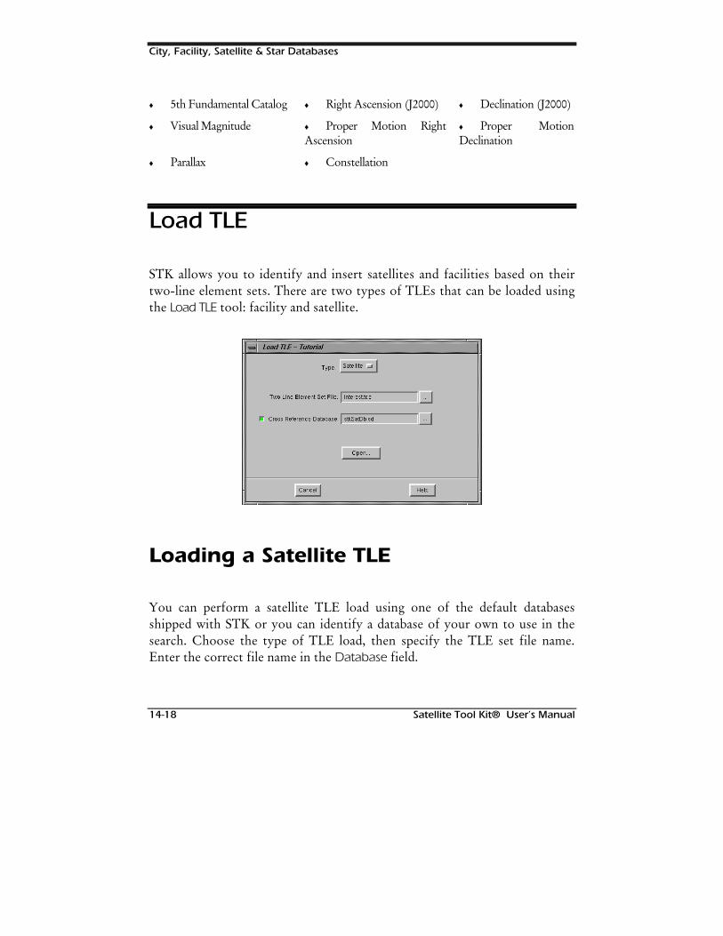
City, Facility, Satellite & Star Databases
14-18 Satellite Tool Kit® User’s Manual
♦ 5th Fundamental Catalog ♦ Right Ascension (J2000) ♦ Declination (J2000)
♦ Visual Magnitude ♦ Proper Motion RightAscension
♦ Proper MotionDeclination
♦ Parallax ♦ Constellation
Load TLE
STK allows you to identify and insert satellites and facilities based on theirtwo-line element sets. There are two types of TLEs that can be loaded usingthe Load TLE tool: facility and satellite.
Loading a Satellite TLE
You can perform a satellite TLE load using one of the default databasesshipped with STK or you can identify a database of your own to use in thesearch. Choose the type of TLE load, then specify the TLE set file name.Enter the correct file name in the Database field.
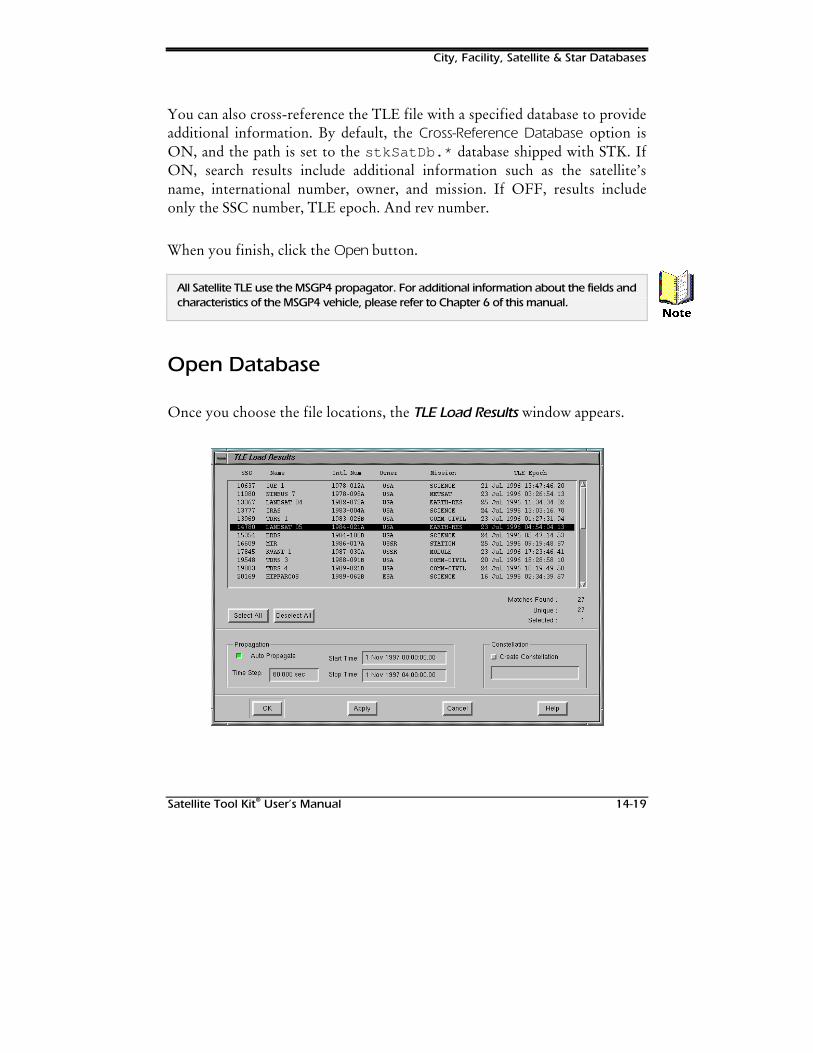
City, Facility, Satellite & Star Databases
Satellite Tool Kit® User’s Manual 14-19
You can also cross-reference the TLE file with a specified database to provideadditional information. By default, the Cross-Reference Database option isON, and the path is set to the stkSatDb.* database shipped with STK. IfON, search results include additional information such as the satellite’sname, international number, owner, and mission. If OFF, results includeonly the SSC number, TLE epoch. And rev number.
When you finish, click the Open button.
All Satellite TLE use the MSGP4 propagator. For additional information about the fields andcharacteristics of the MSGP4 vehicle, please refer to Chapter 6 of this manual.
Open Database
Once you choose the file locations, the TLE Load Results window appears.
1RWH
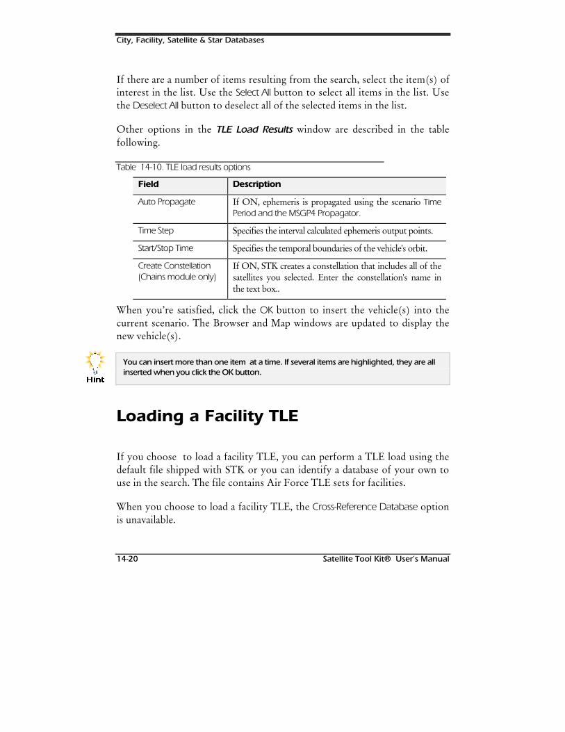
City, Facility, Satellite & Star Databases
14-20 Satellite Tool Kit® User’s Manual
If there are a number of items resulting from the search, select the item(s) ofinterest in the list. Use the Select All button to select all items in the list. Usethe Deselect All button to deselect all of the selected items in the list.
Other options in the TLE Load Results window are described in the tablefollowing.
Table 14-10. TLE load results options
Field Description
Auto Propagate If ON, ephemeris is propagated using the scenario TimePeriod and the MSGP4 Propagator.
Time Step Specifies the interval calculated ephemeris output points.
Start/Stop Time Specifies the temporal boundaries of the vehicle's orbit.
Create Constellation(Chains module only)
If ON, STK creates a constellation that includes all of thesatellites you selected. Enter the constellation's name inthe text box..
When you’re satisfied, click the OK button to insert the vehicle(s) into thecurrent scenario. The Browser and Map windows are updated to display thenew vehicle(s).
You can insert more than one item at a time. If several items are highlighted, they are allinserted when you click the OK button.
Loading a Facility TLE
If you choose to load a facility TLE, you can perform a TLE load using thedefault file shipped with STK or you can identify a database of your own touse in the search. The file contains Air Force TLE sets for facilities.
When you choose to load a facility TLE, the Cross-Reference Database optionis unavailable.
+LQW
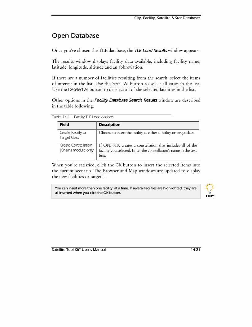
City, Facility, Satellite & Star Databases
Satellite Tool Kit® User’s Manual 14-21
Open Database
Once you've chosen the TLE database, the TLE Load Results window appears.
The results window displays facility data available, including facility name,latitude, longitude, altitude and an abbreviation.
If there are a number of facilities resulting from the search, select the itemsof interest in the list. Use the Select All button to select all cities in the list.Use the Deselect All button to deselect all of the selected facilities in the list.
Other options in the Facility Database Search Results window are describedin the table following.
Table 14-11. Facility TLE Load options
Field Description
Create Facility orTarget Class
Choose to insert the facility as either a facility or target class.
Create Constellation(Chains module only)
If ON, STK creates a constellation that includes all of thefacility you selected. Enter the constellation's name in the textbox.
When you’re satisfied, click the OK button to insert the selected items intothe current scenario. The Browser and Map windows are updated to displaythe new facilities or targets.
You can insert more than one facility at a time. If several facilities are highlighted, they areall inserted when you click the OK button.
+LQW
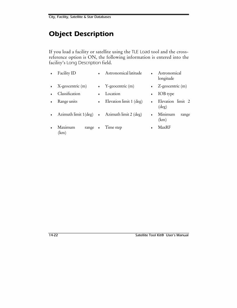
City, Facility, Satellite & Star Databases
14-22 Satellite Tool Kit® User’s Manual
Object Description
If you load a facility or satellite using the TLE Load tool and the cross-reference option is ON, the following information is entered into thefacility’s Long Description field.
♦ Facility ID ♦ Astronomical latitude ♦ Astronomicallongitude
♦ X-geocentric (m) ♦ Y-geocentric (m) ♦ Z-geocentric (m)
♦ Classification ♦ Location ♦ IOB type
♦ Range units ♦ Elevation limit 1 (deg) ♦ Elevation limit 2(deg)
♦ Azimuth limit 1(deg) ♦ Azimuth limit 2 (deg) ♦ Minimum range(km)
♦ Maximum range(km)
♦ Time step ♦ MaxRF
Satellite Tool Kit® User’s Manual 15-1
15REPORTS &
GRAPHS
Overview
The Report and Graph tools in STK summarize static data. They are available formost objects and are helpful in presenting and visualizing relationships among dataelements. You can also include the data from one or more objects in a report orgraph. These tools are useful for high-level presentations of complex information.
Chapter Contents
Using the STK Report/Graph Tool..............................................................15-2
Changing Time Periods for Reports & Graphs ......................................15-3
Managing Report/Graph Styles ............................................................15-4
Report Window .........................................................................................15-5
Report Properties........................................................................................15-6
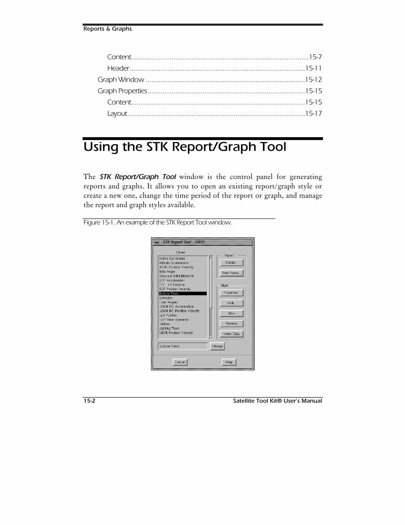
Reports & Graphs
15-2 Satellite Tool Kit® User’s Manual
Content.................................................................................................15-7
Header................................................................................................15-11
Graph Window .......................................................................................15-12
Graph Properties......................................................................................15-15
Content...............................................................................................15-15
Layout.................................................................................................15-17
Using the STK Report/Graph Tool
The STK Report/Graph Tool window is the control panel for generatingreports and graphs. It allows you to open an existing report/graph style orcreate a new one, change the time period of the report or graph, and managethe report and graph styles available.
Figure 15-1. An example of the STK Report Tool window.
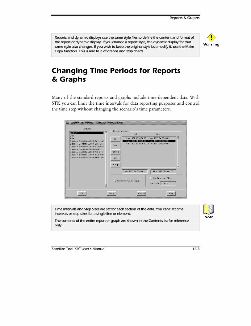
Reports & Graphs
Satellite Tool Kit® User’s Manual 15-3
Reports and dynamic displays use the same style files to define the content and format ofthe report or dynamic display. If you change a report style, the dynamic display for thatsame style also changes. If you wish to keep the original style but modify it, use the MakeCopy function. This is also true of graphs and strip charts
Changing Time Periods for Reports& Graphs
Many of the standard reports and graphs include time-dependent data. WithSTK you can limit the time intervals for data reporting purposes and controlthe time step without changing the scenario’s time parameters.
Time Intervals and Step Sizes are set for each section of the data. You can’t set timeintervals or step sizes for a single line or element.
The contents of the entire report or graph are shown in the Contents list for referenceonly.
:DUQLQJ
1RWH
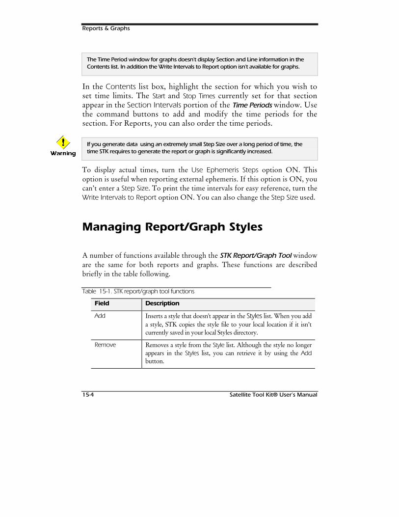
Reports & Graphs
15-4 Satellite Tool Kit® User’s Manual
The Time Period window for graphs doesn't display Section and Line information in theContents list. In addition the Write Intervals to Report option isn't available for graphs.
In the Contents list box, highlight the section for which you wish toset time limits. The Start and Stop Times currently set for that sectionappear in the Section Intervals portion of the Time Periods window. Usethe command buttons to add and modify the time periods for thesection. For Reports, you can also order the time periods.
If you generate data using an extremely small Step Size over a long period of time, thetime STK requires to generate the report or graph is significantly increased.
To display actual times, turn the Use Ephemeris Steps option ON. Thisoption is useful when reporting external ephemeris. If this option is ON, youcan’t enter a Step Size. To print the time intervals for easy reference, turn theWrite Intervals to Report option ON. You can also change the Step Size used.
Managing Report/Graph Styles
A number of functions available through the STK Report/Graph Tool windoware the same for both reports and graphs. These functions are describedbriefly in the table following.
Table 15-1. STK report/graph tool functions
Field Description
Add Inserts a style that doesn't appear in the Styles list. When you adda style, STK copies the style file to your local location if it isn’tcurrently saved in your local Styles directory.
Remove Removes a style from the Style list. Although the style no longerappears in the Styles list, you can retrieve it by using the Addbutton.
:DUQLQJ
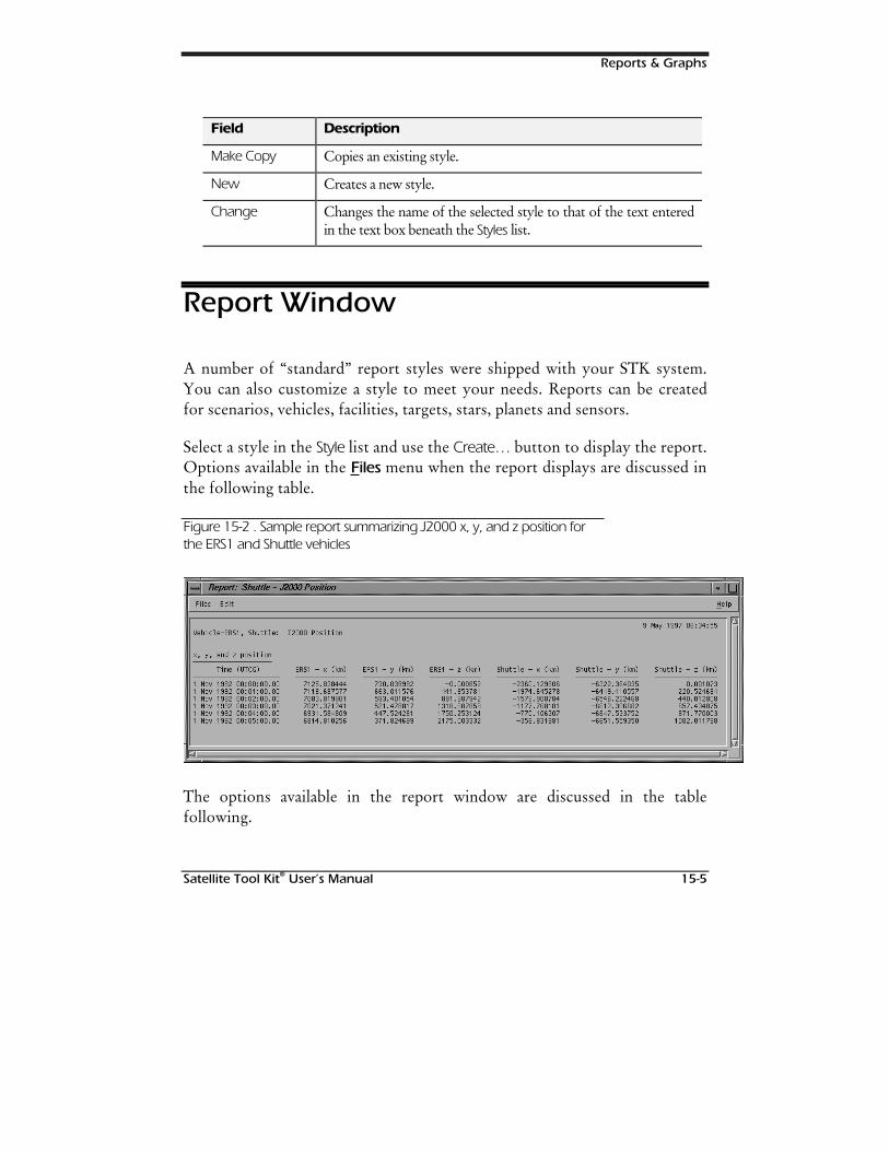
Reports & Graphs
Satellite Tool Kit® User’s Manual 15-5
Field Description
Make Copy Copies an existing style.
New Creates a new style.
Change Changes the name of the selected style to that of the text enteredin the text box beneath the Styles list.
Report Window
A number of “standard” report styles were shipped with your STK system.You can also customize a style to meet your needs. Reports can be createdfor scenarios, vehicles, facilities, targets, stars, planets and sensors.
Select a style in the Style list and use the Create… button to display the report.Options available in the Files menu when the report displays are discussed inthe following table.
Figure 15-2 . Sample report summarizing J2000 x, y, and z position forthe ERS1 and Shuttle vehicles
The options available in the report window are discussed in the tablefollowing.
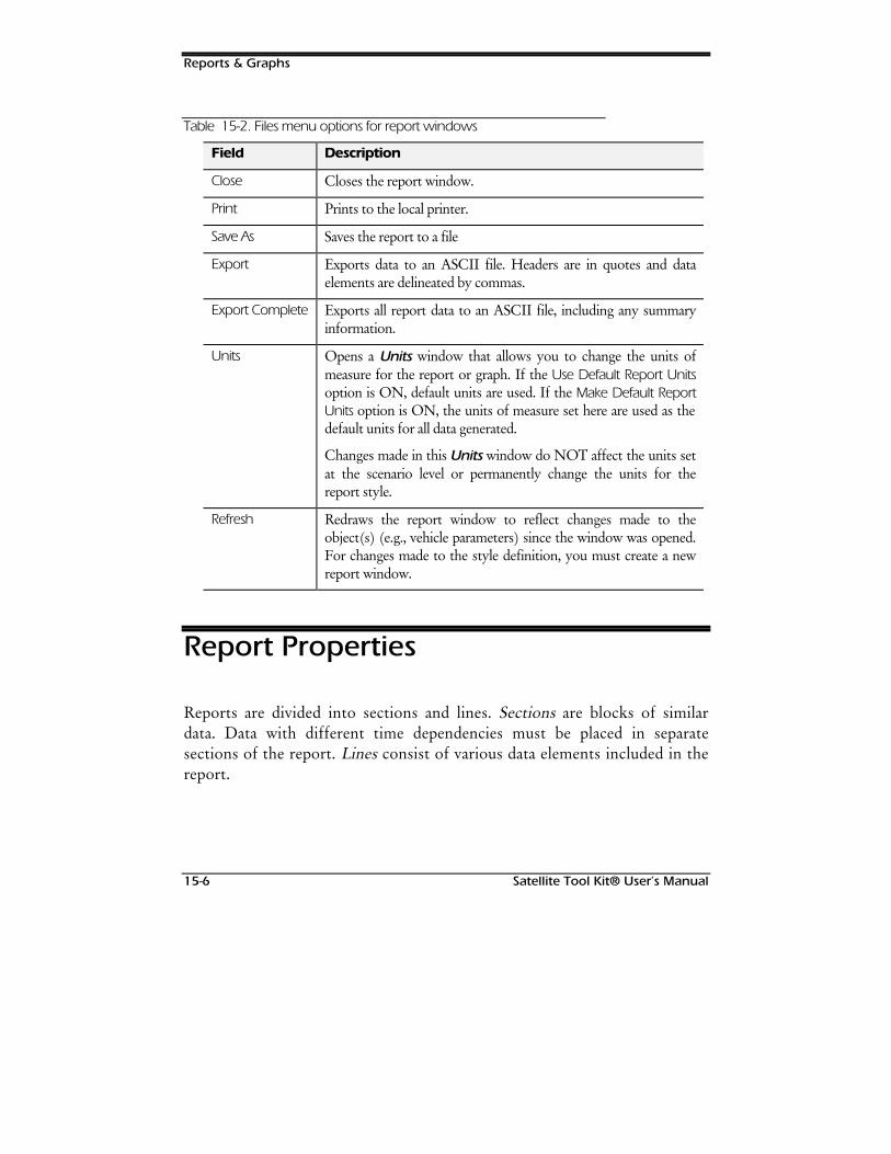
Reports & Graphs
15-6 Satellite Tool Kit® User’s Manual
Table 15-2. Files menu options for report windows
Field Description
Close Closes the report window.
Print Prints to the local printer.
Save As Saves the report to a file
Export Exports data to an ASCII file. Headers are in quotes and dataelements are delineated by commas.
Export Complete Exports all report data to an ASCII file, including any summaryinformation.
Units Opens a Units window that allows you to change the units ofmeasure for the report or graph. If the Use Default Report Unitsoption is ON, default units are used. If the Make Default ReportUnits option is ON, the units of measure set here are used as thedefault units for all data generated.
Changes made in this Units window do NOT affect the units setat the scenario level or permanently change the units for thereport style.
Refresh Redraws the report window to reflect changes made to theobject(s) (e.g., vehicle parameters) since the window was opened.For changes made to the style definition, you must create a newreport window.
Report Properties
Reports are divided into sections and lines. Sections are blocks of similardata. Data with different time dependencies must be placed in separatesections of the report. Lines consist of various data elements included in thereport.
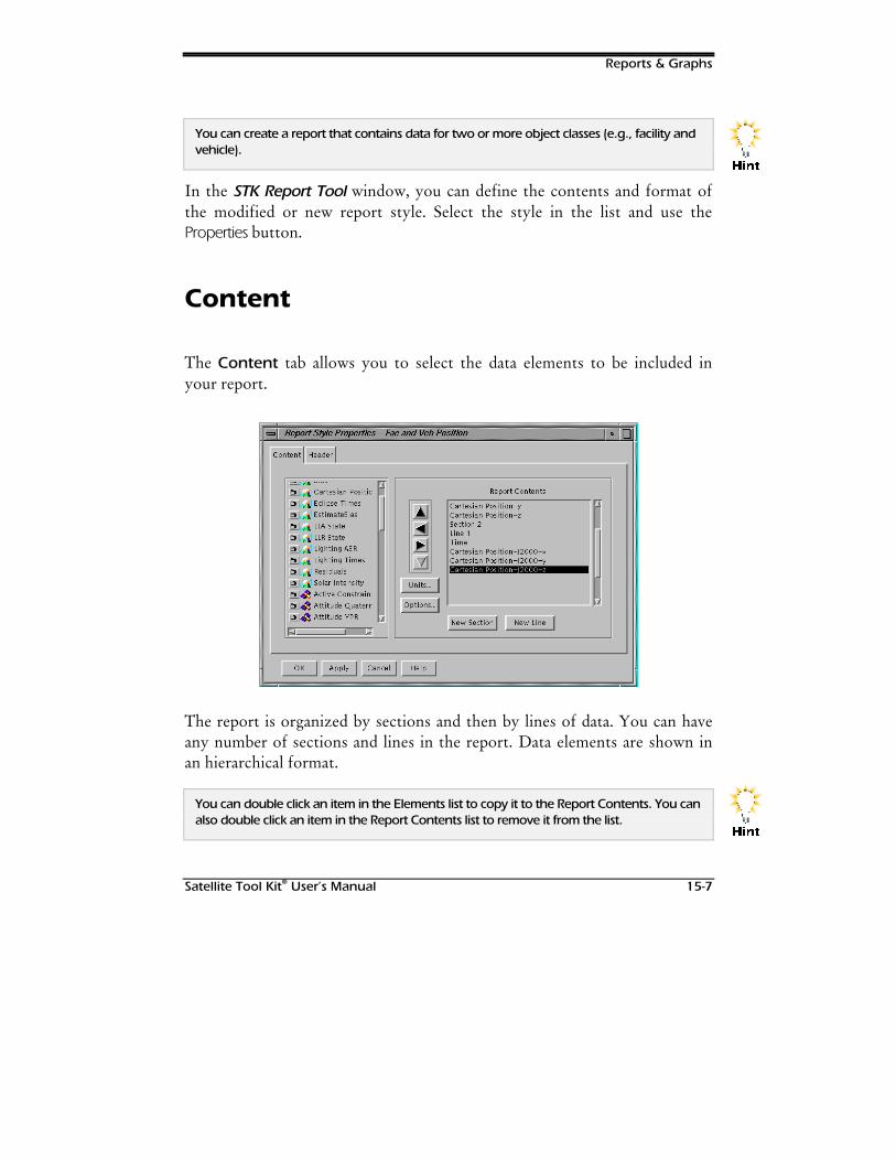
Reports & Graphs
Satellite Tool Kit® User’s Manual 15-7
You can create a report that contains data for two or more object classes (e.g., facility andvehicle).
In the STK Report Tool window, you can define the contents and format ofthe modified or new report style. Select the style in the list and use theProperties button.
Content
The Content tab allows you to select the data elements to be included inyour report.
The report is organized by sections and then by lines of data. You can haveany number of sections and lines in the report. Data elements are shown inan hierarchical format.
You can double click an item in the Elements list to copy it to the Report Contents. You canalso double click an item in the Report Contents list to remove it from the list.
+LQW
+LQW
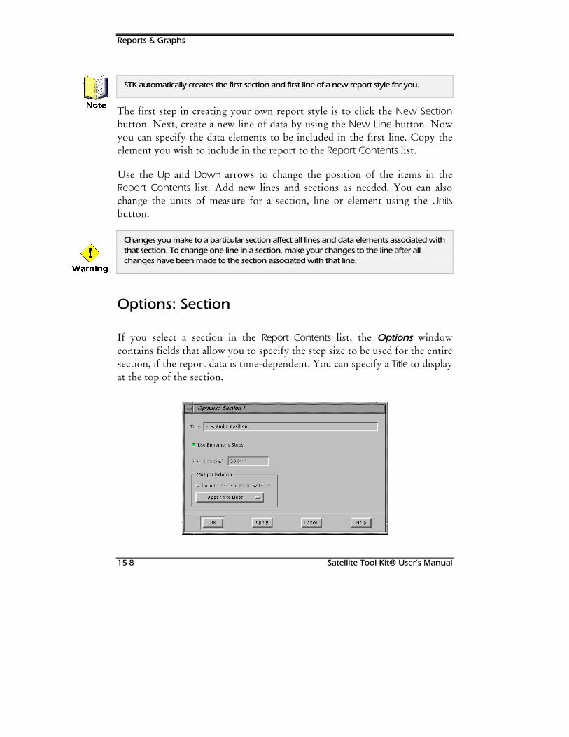
Reports & Graphs
15-8 Satellite Tool Kit® User’s Manual
STK automatically creates the first section and first line of a new report style for you.
The first step in creating your own report style is to click the New Sectionbutton. Next, create a new line of data by using the New Line button. Nowyou can specify the data elements to be included in the first line. Copy theelement you wish to include in the report to the Report Contents list.
Use the Up and Down arrows to change the position of the items in theReport Contents list. Add new lines and sections as needed. You can alsochange the units of measure for a section, line or element using the Unitsbutton.
Changes you make to a particular section affect all lines and data elements associated withthat section. To change one line in a section, make your changes to the line after allchanges have been made to the section associated with that line.
Options: Section
If you select a section in the Report Contents list, the Options windowcontains fields that allow you to specify the step size to be used for the entiresection, if the report data is time-dependent. You can specify a Title to displayat the top of the section.
1RWH
:DUQLQJ
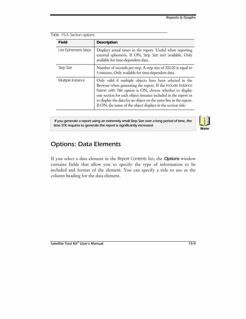
Reports & Graphs
Satellite Tool Kit® User’s Manual 15-9
Table 15-3. Section options
Field Description
Use Ephemeris Steps Displays actual times in the report. Useful when reportingexternal ephemeris. If ON, Step Size isn't available. Onlyavailable for time-dependent data.
Step Size Number of seconds per step. A step size of 300.00 is equal to5 minutes. Only available for time-dependent data.
Multiple Instance Only valid if multiple objects have been selected in theBrowser when generating the report. If the Include InstanceName with Title option is ON, choose whether to displayone section for each object instance included in the report orto display the data for an object on the same line in the report.If ON, the name of the object displays in the section title.
If you generate a report using an extremely small Step Size over a long period of time, thetime STK requires to generate the report is significantly increased.
Options: Data Elements
If you select a data element in the Report Contents list, the Options windowcontains fields that allow you to specify the type of information to beincluded and format of the element. You can specify a title to use as thecolumn heading for the data element.
1RWH
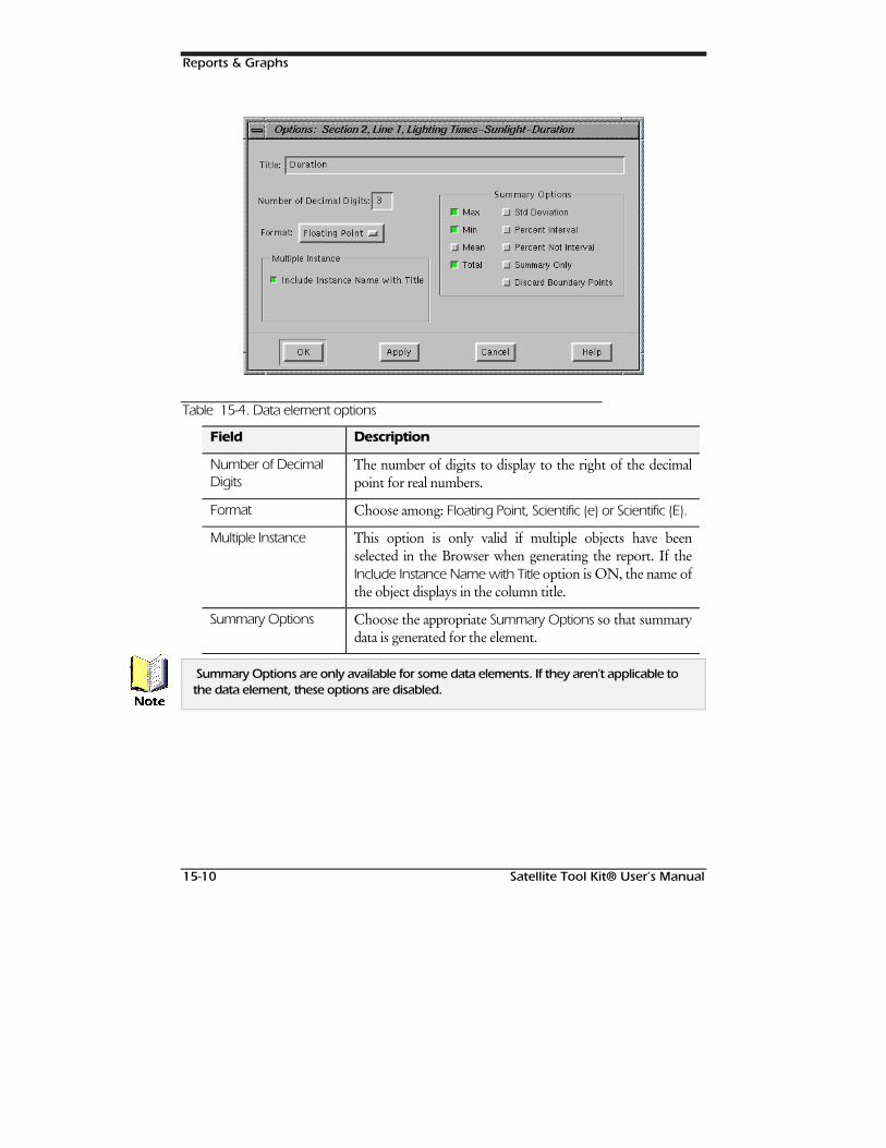
Reports & Graphs
15-10 Satellite Tool Kit® User’s Manual
Table 15-4. Data element options
Field Description
Number of DecimalDigits
The number of digits to display to the right of the decimalpoint for real numbers.
Format Choose among: Floating Point, Scientific (e) or Scientific (E).
Multiple Instance This option is only valid if multiple objects have beenselected in the Browser when generating the report. If theInclude Instance Name with Title option is ON, the name ofthe object displays in the column title.
Summary Options Choose the appropriate Summary Options so that summarydata is generated for the element.
Summary Options are only available for some data elements. If they aren’t applicable tothe data element, these options are disabled.
1RWH
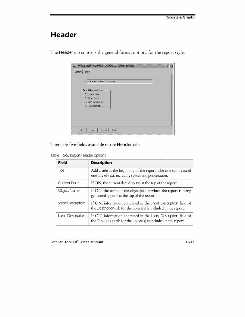
Reports & Graphs
Satellite Tool Kit® User’s Manual 15-11
Header
The Header tab controls the general format options for the report style.
There are five fields available in the Header tab.
Table 15-5. Report Header options
Field Description
Title Add a title at the beginning of the report. The title can’t exceedone line of text, including spaces and punctuation.
Current Date If ON, the current date displays at the top of the report.
Object Name If ON, the name of the object(s) for which the report is beinggenerated appears at the top of the report.
Short Description If ON, information contained in the Short Description field ofthe Description tab for the object(s) is included in the report.
Long Description If ON, information contained in the Long Description field ofthe Description tab for the object(s) is included in the report.
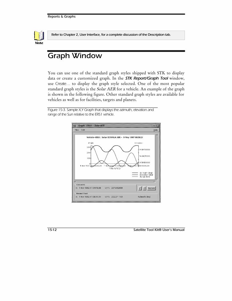
Reports & Graphs
15-12 Satellite Tool Kit® User’s Manual
Refer to Chapter 2, User Interface, for a complete discussion of the Description tab.
Graph Window
You can use one of the standard graph styles shipped with STK to displaydata or create a customized graph. In the STK Report/Graph Tool window,use Create… to display the graph style selected. One of the most popularstandard graph styles is the Solar AER for a vehicle. An example of the graphis shown in the following figure. Other standard graph styles are available forvehicles as well as for facilities, targets and planets.
Figure 15-3. Sample X,Y Graph that displays the azimuth, elevation andrange of the Sun relative to the ERS1 vehicle.
1RWH
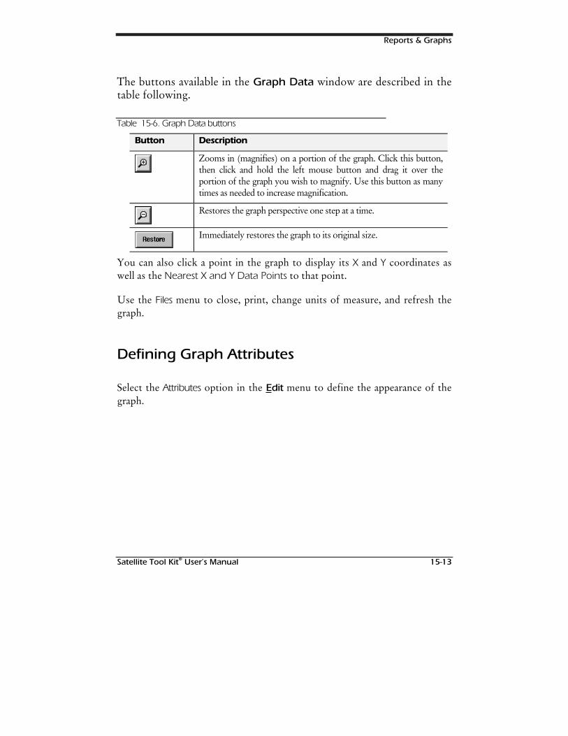
Reports & Graphs
Satellite Tool Kit® User’s Manual 15-13
The buttons available in the Graph Data window are described in thetable following.
Table 15-6. Graph Data buttons
Button Description
Zooms in (magnifies) on a portion of the graph. Click this button,then click and hold the left mouse button and drag it over theportion of the graph you wish to magnify. Use this button as manytimes as needed to increase magnification.
Restores the graph perspective one step at a time.
Immediately restores the graph to its original size.
You can also click a point in the graph to display its X and Y coordinates aswell as the Nearest X and Y Data Points to that point.
Use the Files menu to close, print, change units of measure, and refresh thegraph.
Defining Graph Attributes
Select the Attributes option in the Edit menu to define the appearance of thegraph.
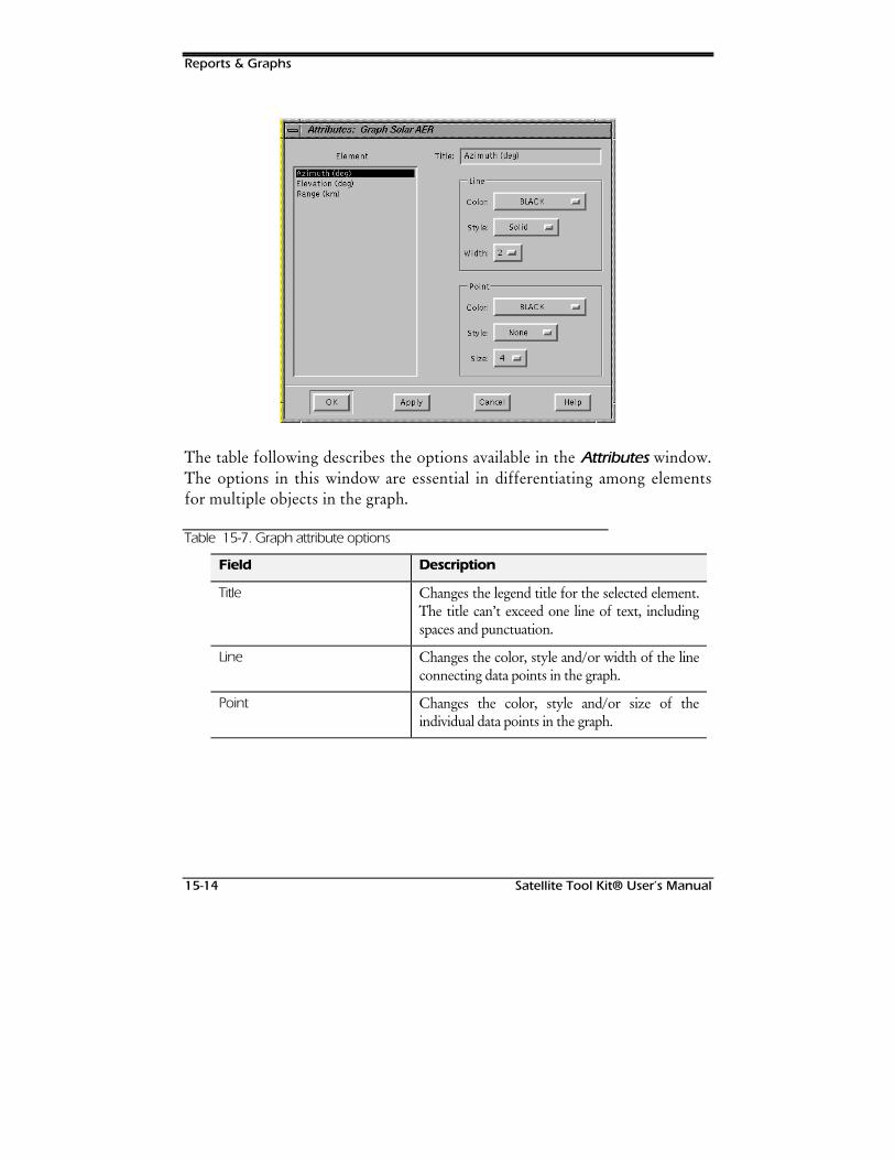
Reports & Graphs
15-14 Satellite Tool Kit® User’s Manual
The table following describes the options available in the Attributes window.The options in this window are essential in differentiating among elementsfor multiple objects in the graph.
Table 15-7. Graph attribute options
Field Description
Title Changes the legend title for the selected element.The title can’t exceed one line of text, includingspaces and punctuation.
Line Changes the color, style and/or width of the lineconnecting data points in the graph.
Point Changes the color, style and/or size of theindividual data points in the graph.

Reports & Graphs
Satellite Tool Kit® User’s Manual 15-15
Graph Properties
In the STK Graph Tool window, you can define the contents and format ofthe modified or new graph style. Select the style in the list and use theProperties button
Content
The Content tab allows you to select the data elements to be included inyour graph.
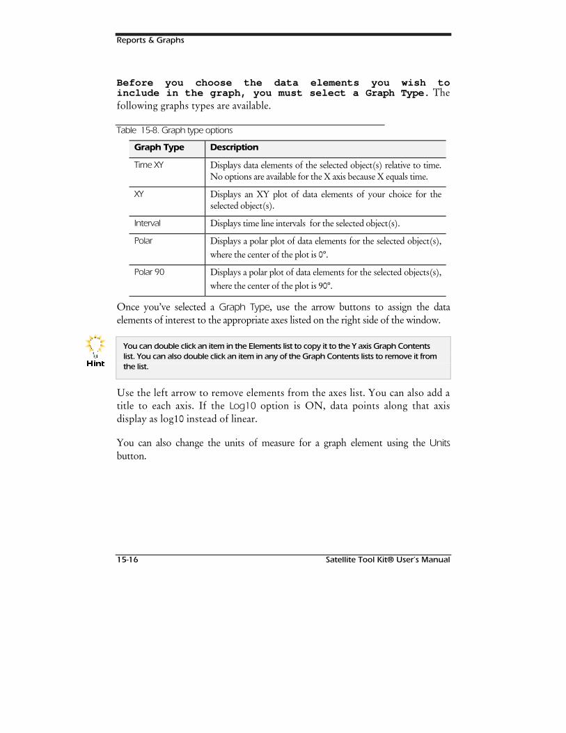
Reports & Graphs
15-16 Satellite Tool Kit® User’s Manual
Before you choose the data elements you wish toinclude in the graph, you must select a Graph Type. Thefollowing graphs types are available.
Table 15-8. Graph type options
Graph Type Description
Time XY Displays data elements of the selected object(s) relative to time.No options are available for the X axis because X equals time.
XY Displays an XY plot of data elements of your choice for theselected object(s).
Interval Displays time line intervals for the selected object(s).
Polar Displays a polar plot of data elements for the selected object(s),where the center of the plot is 0°.
Polar 90 Displays a polar plot of data elements for the selected objects(s),where the center of the plot is 90°.
Once you’ve selected a Graph Type, use the arrow buttons to assign the dataelements of interest to the appropriate axes listed on the right side of the window.
You can double click an item in the Elements list to copy it to the Y axis Graph Contentslist. You can also double click an item in any of the Graph Contents lists to remove it fromthe list.
Use the left arrow to remove elements from the axes list. You can also add atitle to each axis. If the Log10 option is ON, data points along that axisdisplay as log10 instead of linear.
You can also change the units of measure for a graph element using the Unitsbutton.
+LQW
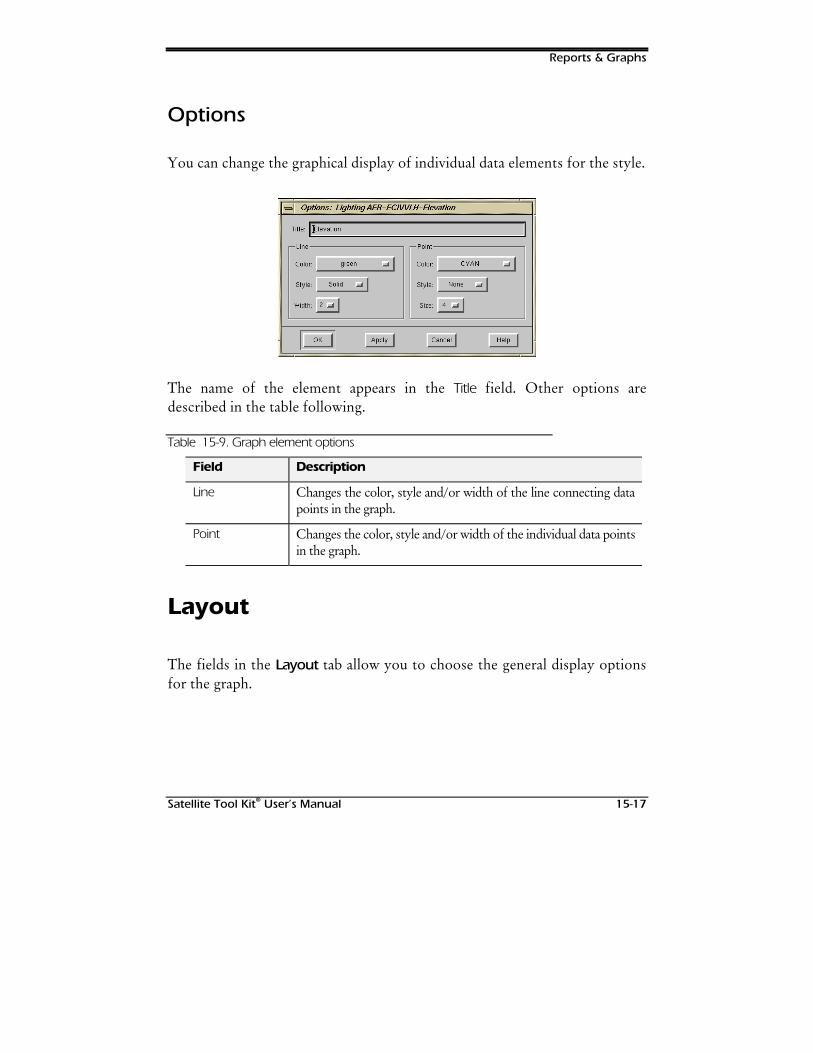
Reports & Graphs
Satellite Tool Kit® User’s Manual 15-17
Options
You can change the graphical display of individual data elements for the style.
The name of the element appears in the Title field. Other options aredescribed in the table following.
Table 15-9. Graph element options
Field Description
Line Changes the color, style and/or width of the line connecting datapoints in the graph.
Point Changes the color, style and/or width of the individual data pointsin the graph.
Layout
The fields in the Layout tab allow you to choose the general display optionsfor the graph.
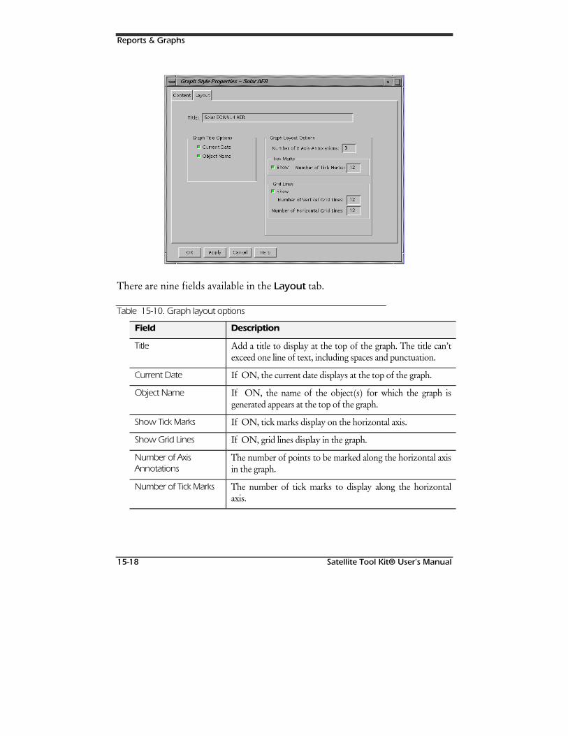
Reports & Graphs
15-18 Satellite Tool Kit® User’s Manual
There are nine fields available in the Layout tab.
Table 15-10. Graph layout options
Field Description
Title Add a title to display at the top of the graph. The title can’texceed one line of text, including spaces and punctuation.
Current Date If ON, the current date displays at the top of the graph.
Object Name If ON, the name of the object(s) for which the graph isgenerated appears at the top of the graph.
Show Tick Marks If ON, tick marks display on the horizontal axis.
Show Grid Lines If ON, grid lines display in the graph.
Number of AxisAnnotations
The number of points to be marked along the horizontal axisin the graph.
Number of Tick Marks The number of tick marks to display along the horizontalaxis.

Reports & Graphs
Satellite Tool Kit® User’s Manual 15-19
Field Description
Number of VerticalGrid Lines
The number of grid lines to display vertically on the graph.
Number of HorizontalGrid Lines
The number of grid lines to display horizontally on thegraph.

Reports & Graphs
15-20 Satellite Tool Kit® User’s Manual
127(6
Satellite Tool Kit® User’s Manual 16-1
16DYNAMIC
DISPLAYS & STRIPCHARTS
Overview
STK now features a Strip Chart tool that displays user-selected data in graphform as you animate the scenario. The Strip Chart is useful when you wish tovisualize dynamic data elements over a period of time. Another feature that isuseful in analyzing data is the Dynamic Display tool, which provides textupdates during animation so that you can view changes to selected elementsover a period of time.
Chapter Contents
Overview ...................................................................................................16-1
Chapter Contents.......................................................................................16-1

Dynamic Displays & Strip Charts
16-2 Satellite Tool Kit® User’s Manual
The STK Dynamic Display/Strip Chart Tool Window ..................................16-2
Managing Dynamic Display/Strip Chart Styles ......................................16-3
Dynamic Display Window .........................................................................16-4
Dynamic Display Properties........................................................................16-5
Content.................................................................................................16-6
Strip Chart Window ...................................................................................16-8
Strip Chart Properties................................................................................16-10
Content...............................................................................................16-11
Layout.................................................................................................16-13
The STK Dynamic Display/Strip ChartTool Window
The STK Dynamic Display/Strip Chart Tool window is the control panel forgenerating dynamic display reports and strip charts. It allows you to open anexisting style or create a new one and manage the dynamic display and stripchart styles available.
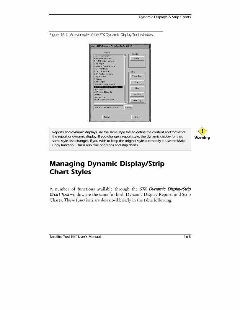
Dynamic Displays & Strip Charts
Satellite Tool Kit® User’s Manual 16-3
Figure 16-1. An example of the STK Dynamic Display Tool window.
Reports and dynamic displays use the same style files to define the content and format ofthe report or dynamic display. If you change a report style, the dynamic display for thatsame style also changes. If you wish to keep the original style but modify it, use the MakeCopy function. This is also true of graphs and strip charts.
Managing Dynamic Display/StripChart Styles
A number of functions available through the STK Dynamic Display/StripChart Tool window are the same for both Dynamic Display Reports and StripCharts. These functions are described briefly in the table following.
:DUQLQJ
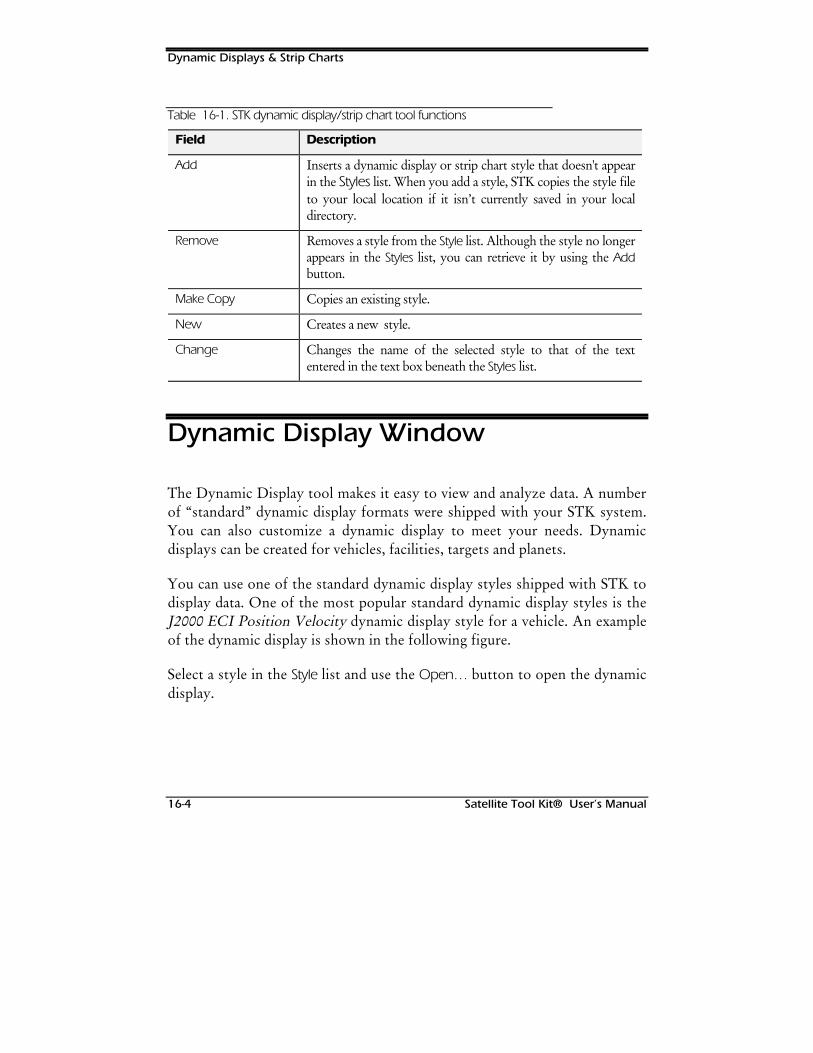
Dynamic Displays & Strip Charts
16-4 Satellite Tool Kit® User’s Manual
Table 16-1. STK dynamic display/strip chart tool functions
Field Description
Add Inserts a dynamic display or strip chart style that doesn't appearin the Styles list. When you add a style, STK copies the style fileto your local location if it isn’t currently saved in your localdirectory.
Remove Removes a style from the Style list. Although the style no longerappears in the Styles list, you can retrieve it by using the Addbutton.
Make Copy Copies an existing style.
New Creates a new style.
Change Changes the name of the selected style to that of the textentered in the text box beneath the Styles list.
Dynamic Display Window
The Dynamic Display tool makes it easy to view and analyze data. A numberof “standard” dynamic display formats were shipped with your STK system.You can also customize a dynamic display to meet your needs. Dynamicdisplays can be created for vehicles, facilities, targets and planets.
You can use one of the standard dynamic display styles shipped with STK todisplay data. One of the most popular standard dynamic display styles is theJ2000 ECI Position Velocity dynamic display style for a vehicle. An exampleof the dynamic display is shown in the following figure.
Select a style in the Style list and use the Open… button to open the dynamicdisplay.
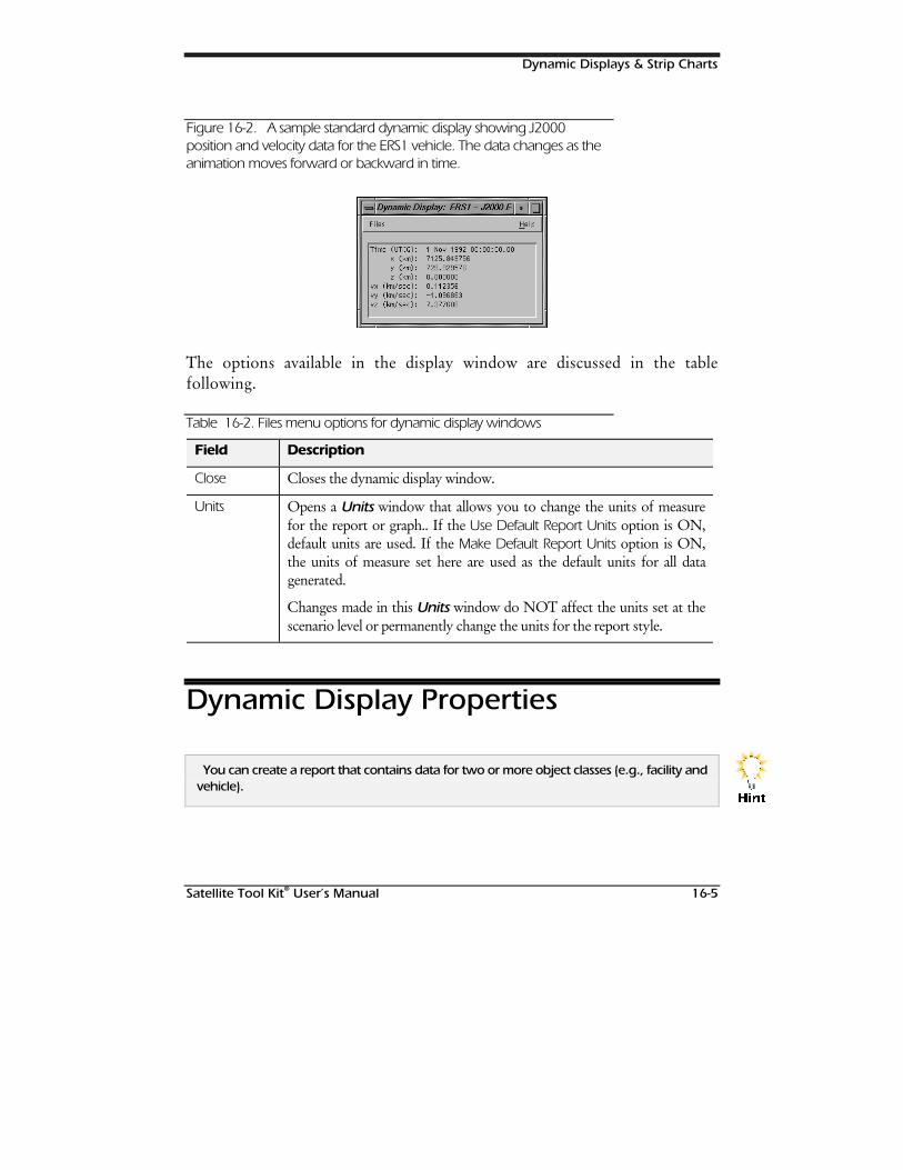
Dynamic Displays & Strip Charts
Satellite Tool Kit® User’s Manual 16-5
Figure 16-2. A sample standard dynamic display showing J2000position and velocity data for the ERS1 vehicle. The data changes as theanimation moves forward or backward in time.
The options available in the display window are discussed in the tablefollowing.
Table 16-2. Files menu options for dynamic display windows
Field Description
Close Closes the dynamic display window.
Units Opens a Units window that allows you to change the units of measurefor the report or graph.. If the Use Default Report Units option is ON,default units are used. If the Make Default Report Units option is ON,the units of measure set here are used as the default units for all datagenerated.
Changes made in this Units window do NOT affect the units set at thescenario level or permanently change the units for the report style.
Dynamic Display Properties
You can create a report that contains data for two or more object classes (e.g., facility andvehicle).
+LQW
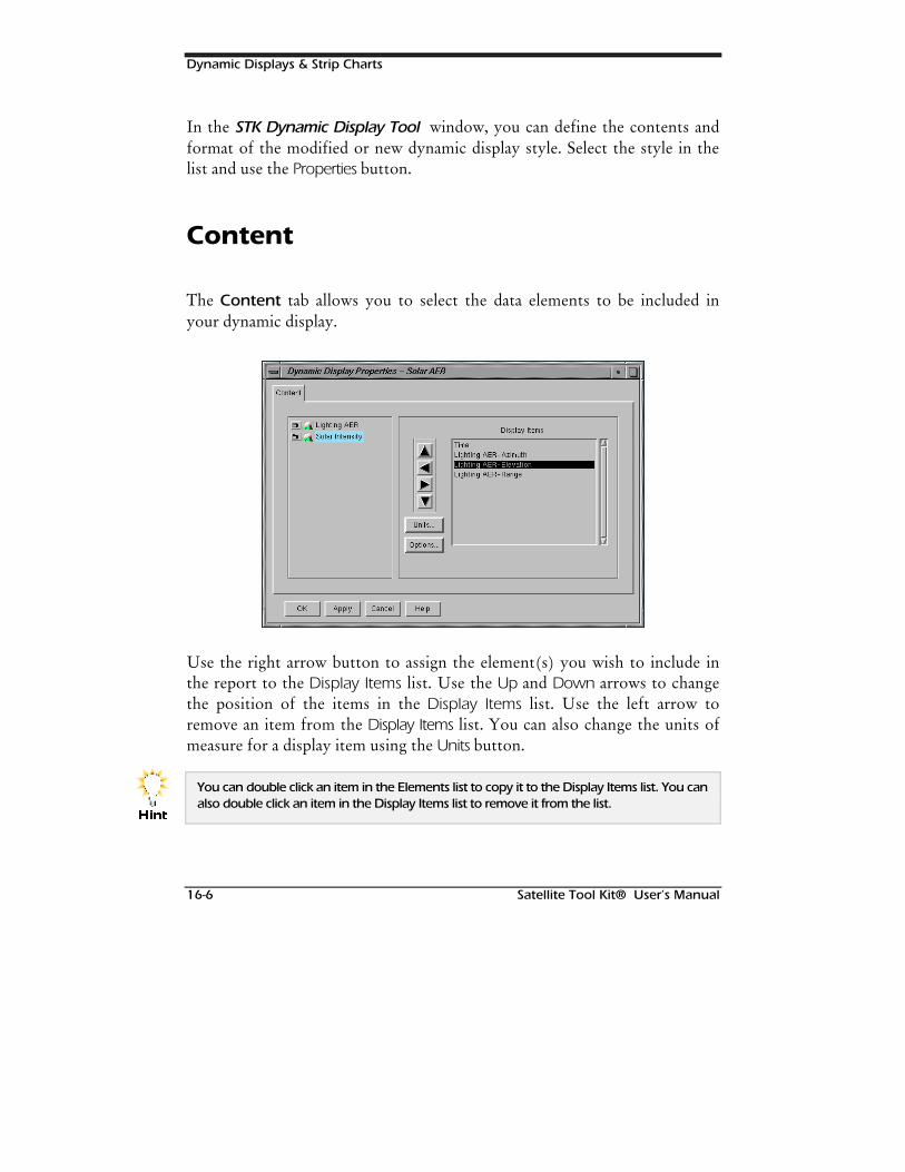
Dynamic Displays & Strip Charts
16-6 Satellite Tool Kit® User’s Manual
In the STK Dynamic Display Tool window, you can define the contents andformat of the modified or new dynamic display style. Select the style in thelist and use the Properties button.
Content
The Content tab allows you to select the data elements to be included inyour dynamic display.
Use the right arrow button to assign the element(s) you wish to include inthe report to the Display Items list. Use the Up and Down arrows to changethe position of the items in the Display Items list. Use the left arrow toremove an item from the Display Items list. You can also change the units ofmeasure for a display item using the Units button.
You can double click an item in the Elements list to copy it to the Display Items list. You canalso double click an item in the Display Items list to remove it from the list.
+LQW
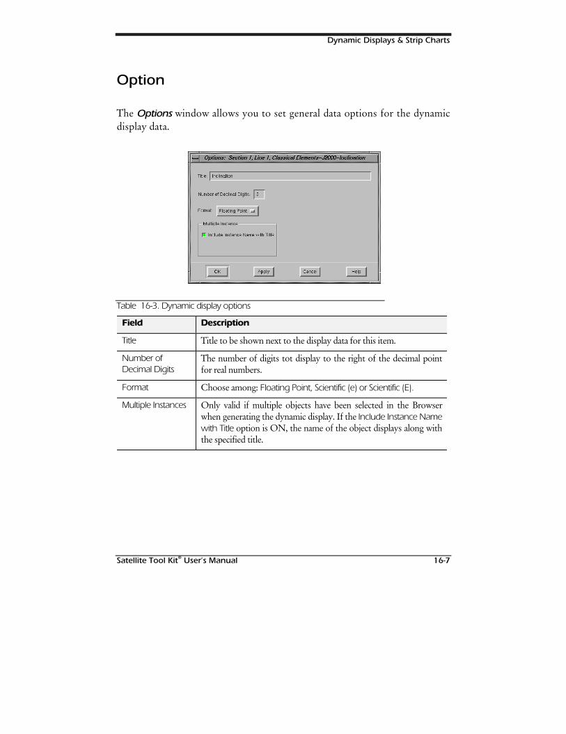
Dynamic Displays & Strip Charts
Satellite Tool Kit® User’s Manual 16-7
Option
The Options window allows you to set general data options for the dynamicdisplay data.
Table 16-3. Dynamic display options
Field Description
Title Title to be shown next to the display data for this item.
Number ofDecimal Digits
The number of digits tot display to the right of the decimal pointfor real numbers.
Format Choose among: Floating Point, Scientific (e) or Scientific (E).
Multiple Instances Only valid if multiple objects have been selected in the Browserwhen generating the dynamic display. If the Include Instance Namewith Title option is ON, the name of the object displays along withthe specified title.
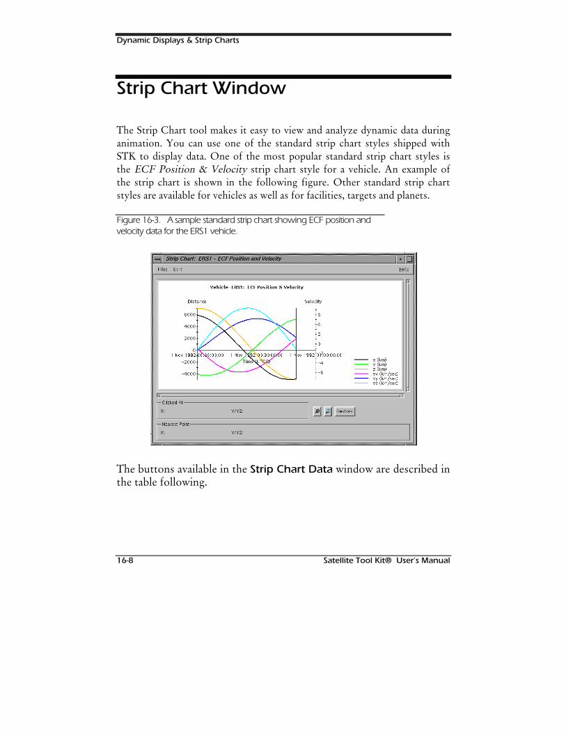
Dynamic Displays & Strip Charts
16-8 Satellite Tool Kit® User’s Manual
Strip Chart Window
The Strip Chart tool makes it easy to view and analyze dynamic data duringanimation. You can use one of the standard strip chart styles shipped withSTK to display data. One of the most popular standard strip chart styles isthe ECF Position & Velocity strip chart style for a vehicle. An example ofthe strip chart is shown in the following figure. Other standard strip chartstyles are available for vehicles as well as for facilities, targets and planets.
Figure 16-3. A sample standard strip chart showing ECF position andvelocity data for the ERS1 vehicle.
The buttons available in the Strip Chart Data window are described inthe table following.
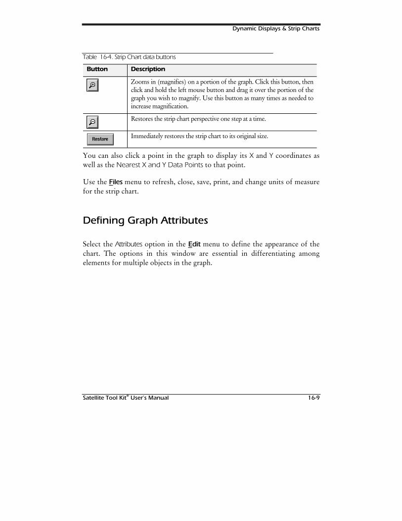
Dynamic Displays & Strip Charts
Satellite Tool Kit® User’s Manual 16-9
Table 16-4. Strip Chart data buttons
Button Description
Zooms in (magnifies) on a portion of the graph. Click this button, thenclick and hold the left mouse button and drag it over the portion of thegraph you wish to magnify. Use this button as many times as needed toincrease magnification.
Restores the strip chart perspective one step at a time.
Immediately restores the strip chart to its original size.
You can also click a point in the graph to display its X and Y coordinates aswell as the Nearest X and Y Data Points to that point.
Use the Files menu to refresh, close, save, print, and change units of measurefor the strip chart.
Defining Graph Attributes
Select the Attributes option in the Edit menu to define the appearance of thechart. The options in this window are essential in differentiating amongelements for multiple objects in the graph.
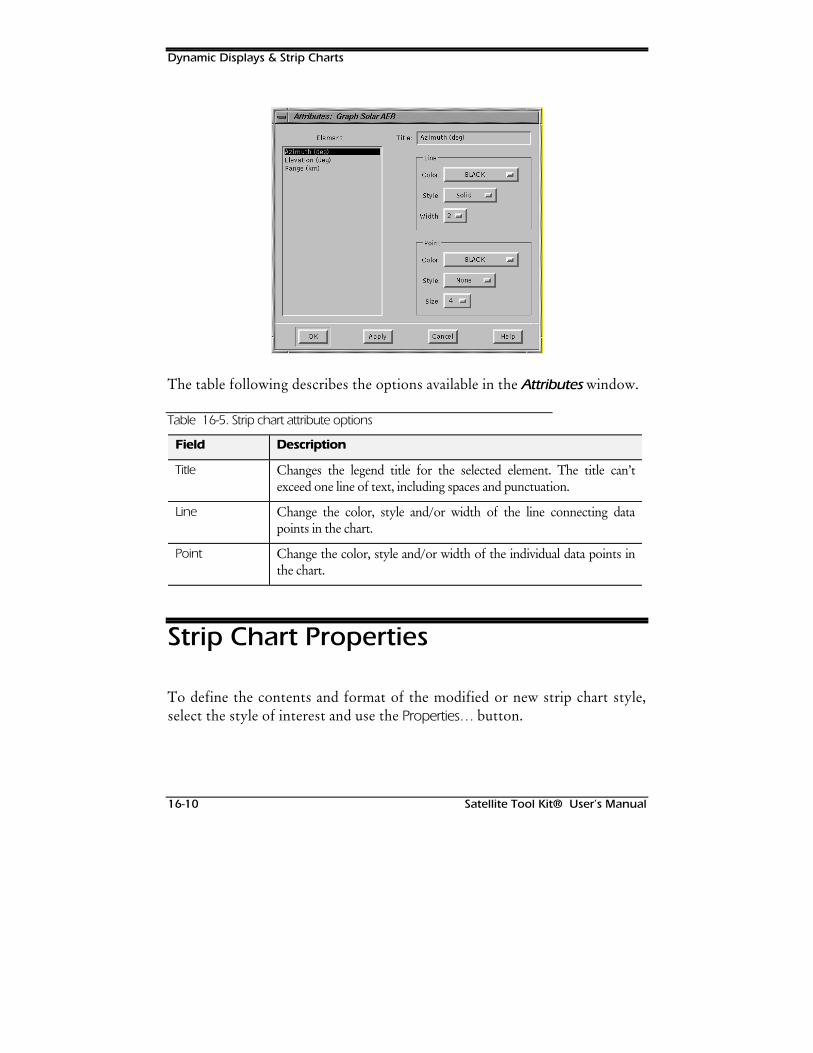
Dynamic Displays & Strip Charts
16-10 Satellite Tool Kit® User’s Manual
The table following describes the options available in the Attributes window.
Table 16-5. Strip chart attribute options
Field Description
Title Changes the legend title for the selected element. The title can’texceed one line of text, including spaces and punctuation.
Line Change the color, style and/or width of the line connecting datapoints in the chart.
Point Change the color, style and/or width of the individual data points inthe chart.
Strip Chart Properties
To define the contents and format of the modified or new strip chart style,select the style of interest and use the Properties… button.
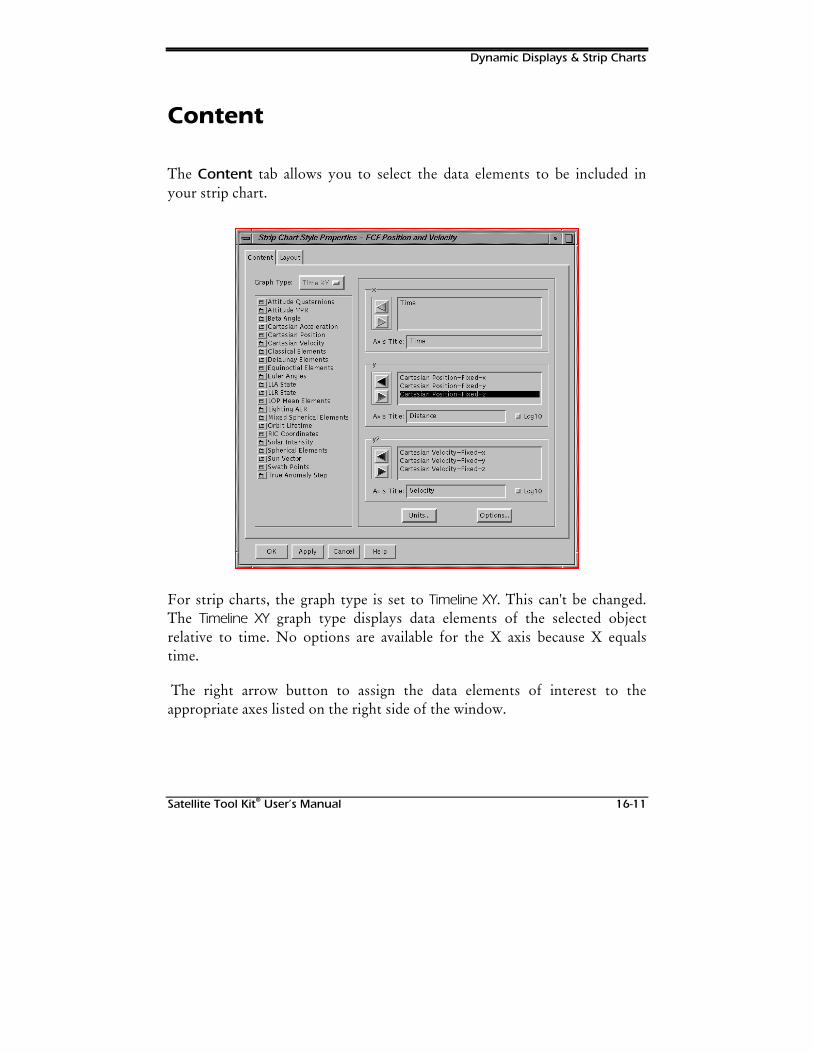
Dynamic Displays & Strip Charts
Satellite Tool Kit® User’s Manual 16-11
Content
The Content tab allows you to select the data elements to be included inyour strip chart.
For strip charts, the graph type is set to Timeline XY. This can't be changed.The Timeline XY graph type displays data elements of the selected objectrelative to time. No options are available for the X axis because X equalstime.
The right arrow button to assign the data elements of interest to theappropriate axes listed on the right side of the window.
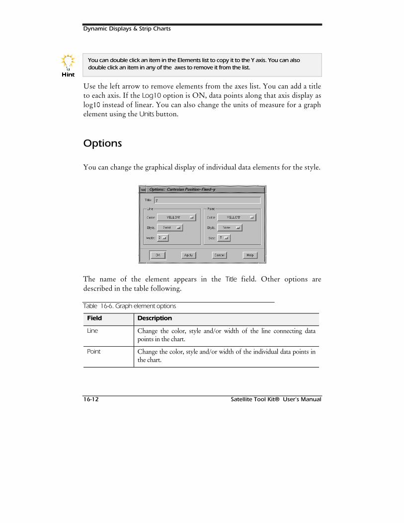
Dynamic Displays & Strip Charts
16-12 Satellite Tool Kit® User’s Manual
You can double click an item in the Elements list to copy it to the Y axis. You can alsodouble click an item in any of the axes to remove it from the list.
Use the left arrow to remove elements from the axes list. You can add a titleto each axis. If the Log10 option is ON, data points along that axis display aslog10 instead of linear. You can also change the units of measure for a graphelement using the Units button.
Options
You can change the graphical display of individual data elements for the style.
The name of the element appears in the Title field. Other options aredescribed in the table following.
Table 16-6. Graph element options
Field Description
Line Change the color, style and/or width of the line connecting datapoints in the chart.
Point Change the color, style and/or width of the individual data points inthe chart.
+LQW

Dynamic Displays & Strip Charts
Satellite Tool Kit® User’s Manual 16-13
Layout
The fields in the Layout tab allow you to choose the general display optionsfor the strip chart.
There are a number of fields available in the Layout tab.
Table 16-7. Strip chart layout options
Field Description
Title Add a title to display at the top of the graph. The title can’t exceedone line of text, including spaces and punctuation.
Current Date If ON, the current date displays at the top of the graph.
Object Name If ON, the name of the object(s) for which the graph is generatedappears at the top of the graph.
Show Tick Marks If ON, tick marks display on the horizontal axis.
Show Grid Lines If ON, grid lines display in the graph.
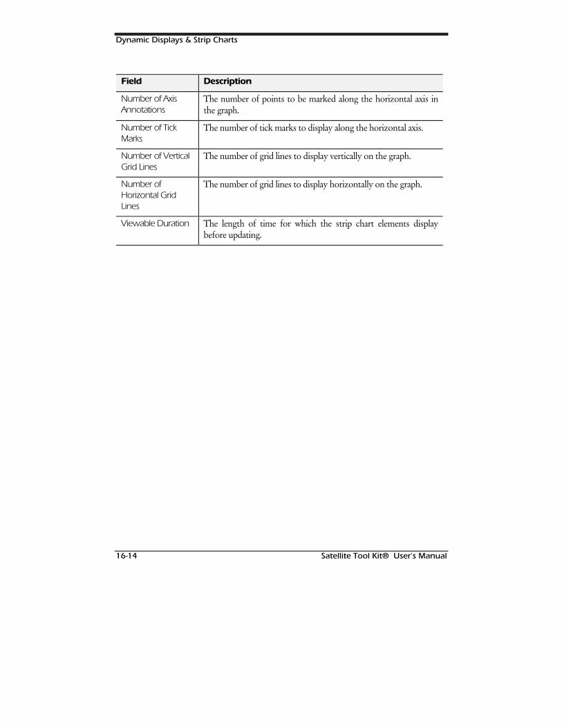
Dynamic Displays & Strip Charts
16-14 Satellite Tool Kit® User’s Manual
Field Description
Number of AxisAnnotations
The number of points to be marked along the horizontal axis inthe graph.
Number of TickMarks
The number of tick marks to display along the horizontal axis.
Number of VerticalGrid Lines
The number of grid lines to display vertically on the graph.
Number ofHorizontal GridLines
The number of grid lines to display horizontally on the graph.
Viewable Duration The length of time for which the strip chart elements displaybefore updating.
Satellite Tool Kit® User’s Manual 17-1
17USING THE STK
HELP MENU
Overview
STK features a Help system that you can reference for help on functions andoptions available in STK. You can access Help files while in the Browserwindow or through individual tabs and windows in STK. STK Help isavailable through the Help menu at the top of the Browser window or byclicking on the Help button on the bottom right-hand side of STK windows.If you access Help through a window other than the Browser, the Help filesfor the specific window display; if you access Help from the Browser, theOverview or Contents displays.
Chapter Contents
STK Help Topics..........................................................................................17-2
Selecting an HMTL Browser..................................................................17-2
Using the STK Help Menu
17-2 Satellite Tool Kit® User’s Manual
Opening Help from the Browser Window...........................................17-3
Opening Help from a Property Window..............................................17-3
Licensing....................................................................................................17-3
Password Window (Initial Start-Up).......................................................17-4
Requesting Licenses by E-Mail or FAX ...................................................17-5
Entering Licenses ..................................................................................17-6
Network Passwords..............................................................................17-8
On-Line Manuals........................................................................................17-9
About STK...................................................................................................17-9
AGI Web Site..............................................................................................17-9
Other Help Menu Items .............................................................................17-9
STK Help Topics
STK offers a comprehensive on-line Help system to assist you in performingtasks and functions in STK. The Help system provides information aboutSTK features as well as instructions for using STK functions and tools.
Selecting an HMTL Browser
For UNIX, STK’s Help files are provided in HTML (hypertext mark-uplanguage) format. When you install STK, you are asked to select the internetBrowser application of choice (Netscape®, Mosaic®, etc.). This applicationis then used to launch the Help files in STK whenever you request Help fromwithin STK. You don’t have to be connected to the internet to use theBrowser but you do need a Browser to view the HTML Help files. Mostworkstations now ship with a Browser. If you don’t have a Browser, you can
Using the STK Help Menu
Satellite Tool Kit® User’s Manual 17-3
purchase Netscape Navigator® at a local computer store or you candownload a shareware version of Netscape at www.netscape.com.
Opening Help from the BrowserWindow
To display Help files from the Browser window, select STK Help Topics fromthe Help menu at the top right-hand corner of the window. If you have anadd-on module, such as Comm or Coverage, Help files are listed as separateitems in the Help menu.
Opening Help from a PropertyWindow
If you need to open the Help system from any Property window, use theHelp button located on the bottom right-hand side of any Property window.A Help file for the specific tab appears in the Help window.
Licensing
To run STK you will need one or more software licenses. The STK interfaceprovides an easy, orderly procedure for obtaining the necessary licenses.
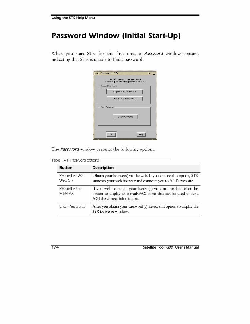
Using the STK Help Menu
17-4 Satellite Tool Kit® User’s Manual
Password Window (Initial Start-Up)
When you start STK for the first time, a Password window appears,indicating that STK is unable to find a password.
The Password window presents the following options:
Table 17-1. Password options
Button Description
Request via AGIWeb Site
Obtain your license(s) via the web. If you choose this option, STKlaunches your web browser and connects you to AGI’s web site.
Request via E-Mail/FAX
If you wish to obtain your license(s) via e-mail or fax, select thisoption to display an e-mail/FAX form that can be used to sendAGI the correct information.
Enter Passwords After you obtain your password(s), select this option to display theSTK Licenses window.
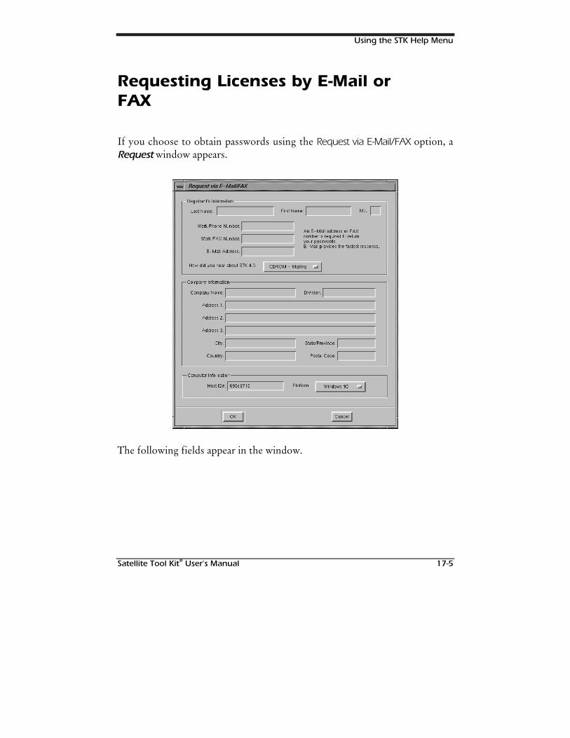
Using the STK Help Menu
Satellite Tool Kit® User’s Manual 17-5
Requesting Licenses by E-Mail orFAX
If you choose to obtain passwords using the Request via E-Mail/FAX option, aRequest window appears.
The following fields appear in the window.
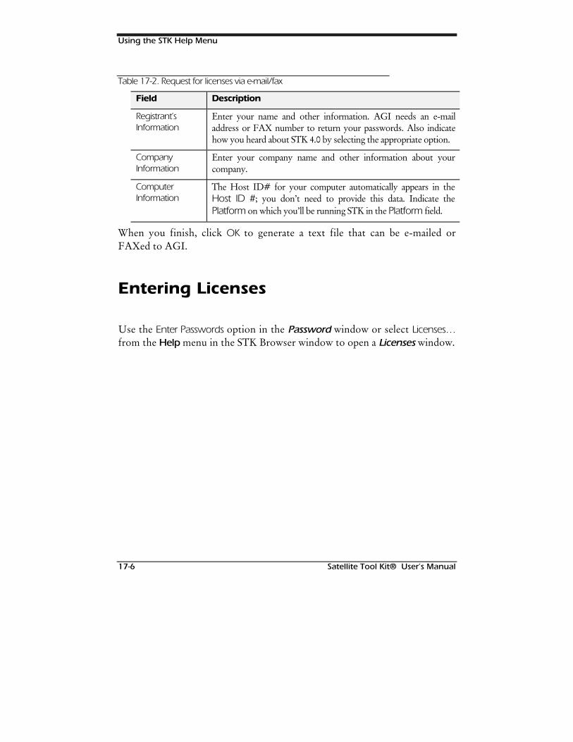
Using the STK Help Menu
17-6 Satellite Tool Kit® User’s Manual
Table 17-2. Request for licenses via e-mail/fax
Field Description
Registrant’sInformation
Enter your name and other information. AGI needs an e-mailaddress or FAX number to return your passwords. Also indicatehow you heard about STK 4.0 by selecting the appropriate option.
CompanyInformation
Enter your company name and other information about yourcompany.
ComputerInformation
The Host ID# for your computer automatically appears in theHost ID #; you don’t need to provide this data. Indicate thePlatform on which you’ll be running STK in the Platform field.
When you finish, click OK to generate a text file that can be e-mailed orFAXed to AGI.
Entering Licenses
Use the Enter Passwords option in the Password window or select Licenses…from the Help menu in the STK Browser window to open a Licenses window.
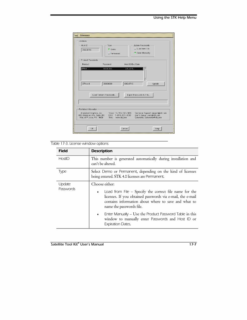
Using the STK Help Menu
Satellite Tool Kit® User’s Manual 17-7
Table 17-3. License window options
Field Description
HostID This number is generated automatically during installation andcan’t be altered.
Type Select Demo or Permanent, depending on the kind of licensesbeing entered. STK 4.0 licenses are Permanent.
UpdatePasswords
Choose either:
♦ Load from File – Specify the correct file name for thelicenses. If you obtained passwords via e-mail, the e-mailcontains information about where to save and what toname the passwords file.
♦ Enter Manually – Use the Product Password Table in thiswindow to manually enter Passwords and Host ID orExpiration Dates.
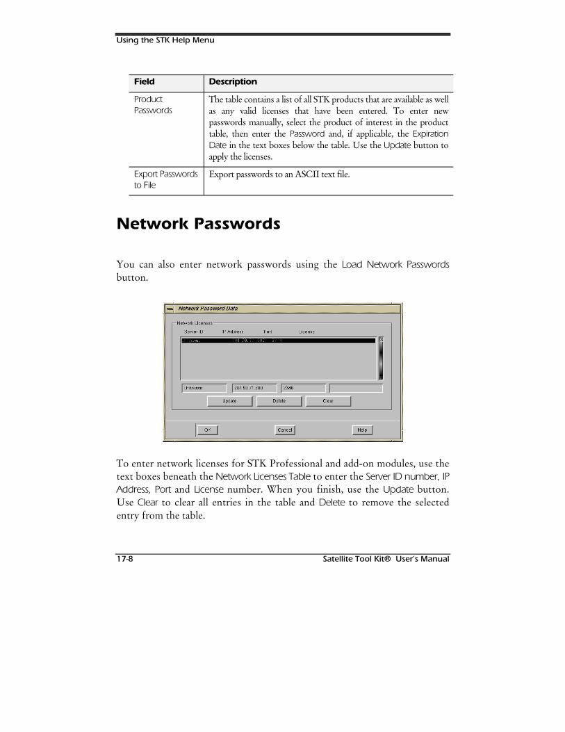
Using the STK Help Menu
17-8 Satellite Tool Kit® User’s Manual
Field Description
ProductPasswords
The table contains a list of all STK products that are available as wellas any valid licenses that have been entered. To enter newpasswords manually, select the product of interest in the producttable, then enter the Password and, if applicable, the ExpirationDate in the text boxes below the table. Use the Update button toapply the licenses.
Export Passwordsto File
Export passwords to an ASCII text file.
Network Passwords
You can also enter network passwords using the Load Network Passwordsbutton.
To enter network licenses for STK Professional and add-on modules, use thetext boxes beneath the Network Licenses Table to enter the Server ID number, IPAddress, Port and License number. When you finish, use the Update button.Use Clear to clear all entries in the table and Delete to remove the selectedentry from the table.
Using the STK Help Menu
Satellite Tool Kit® User’s Manual 17-9
On-Line Manuals
Full user documentation is provided on-line for your convenience. Thesefiles are stored in portable document format (PDF) and can be viewed usingthe Adobe Acrobat Reader 3.0®. When you installed STK, you were askedwhether you wished to install the Reader along with the PDF files. TheReader is also available at www.adobe.com as free-ware. PDF files can beprinted in full. In addition, they are word searchable.
About STK
This selection provides you with valuable information about STK, includingcustomer support numbers and sales information. You can also open thiswindow to determine the software release version you’re using.
AGI Web Site
STK now has an on-line update feature to enable easy updates of TLE sets,databases and more. Just select Online Update from the Help menu to openthe STK web site.
Other Help Menu Items
Additional items in the Browser window’s Help menu include the following:
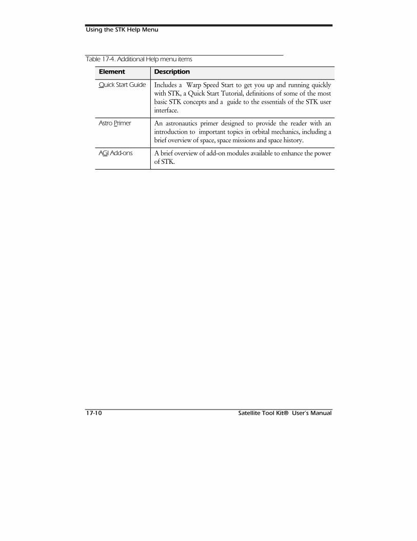
Using the STK Help Menu
17-10 Satellite Tool Kit® User’s Manual
Table 17-4. Additional Help menu items
Element Description
Quick Start Guide Includes a Warp Speed Start to get you up and running quicklywith STK, a Quick Start Tutorial, definitions of some of the mostbasic STK concepts and a guide to the essentials of the STK userinterface.
Astro Primer An astronautics primer designed to provide the reader with anintroduction to important topics in orbital mechanics, including abrief overview of space, space missions and space history.
AGI Add-ons A brief overview of add-on modules available to enhance the powerof STK.
Satellite Tool Kit® User’s Manual 18-1
18CHAINS MODULE
Overview
The STK Chains module is a multisatellite, multitarget/ground stationproductivity tool that is easy to use. Chains provides you with powerfulanalysis capabilities that aren’t available in any other off-the-shelf package.
Chapter Contents
Overview ...................................................................................................18-1
Chains & Constellations..............................................................................18-2
Basic Properties of a Chain.........................................................................18-3
Definition ..............................................................................................18-4
Constellations.............................................................................................18-5
Basic Properties of a Constellation..............................................................18-6
Constellation.........................................................................................18-6
Generating Reports for a Chain .................................................................18-8

Chains Module
18-2 Satellite Tool Kit® User’s Manual
Creating Graphs for Chains..................................................................... 18-12
Dynamic Display Reports & Strip Charts................................................... 18-13
Chains & Constellations
The Chains module allows you to extend the pair-wise analysis capabilities ofSTK to include accesses to and from satellite constellations, ground stationnetworks, groups of targets and multiple sensors. For instance, you candetermine the time period in which a satellite can see a target and a relaystation and the relay station can see a ground station. With Chains, you canalso group objects together — a powerful capability that allows you to checkaccesses to the entire group. For example, you can determine when a tank hasaccess to at least four satellites in the Global Positioning System (GPS)constellation.
In addition, you can easily determine when LandSat can see a target as well asa TDRS relay satellite, and the relay satellite can, in turn, see a ground station.In STK’s Chains module, that chain could be defined as:
Target1 – LandSat – TDRS_East – WhiteSands
You could also define a chain with a target to a LEO satellite to a relaysatellite to a ground station. Or you can solve more sophisticated problemssuch as allowing the use of TDRS-East or -West as the relay satellite. InChains, you would define a constellation of relay satellites and thenincorporate that constellation into a chain.
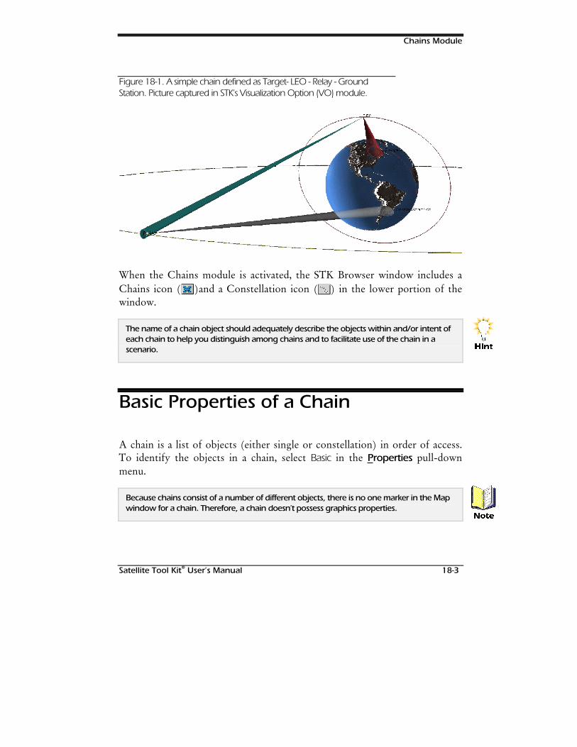
Chains Module
Satellite Tool Kit® User’s Manual 18-3
Figure 18-1. A simple chain defined as Target- LEO - Relay - GroundStation. Picture captured in STK’s Visualization Option (VO) module.
When the Chains module is activated, the STK Browser window includes aChains icon ( )and a Constellation icon ( ) in the lower portion of thewindow.
The name of a chain object should adequately describe the objects within and/or intent ofeach chain to help you distinguish among chains and to facilitate use of the chain in ascenario.
Basic Properties of a Chain
A chain is a list of objects (either single or constellation) in order of access.To identify the objects in a chain, select Basic in the Properties pull-downmenu.
Because chains consist of a number of different objects, there is no one marker in the Mapwindow for a chain. Therefore, a chain doesn’t possess graphics properties.
+LQW
1RWH
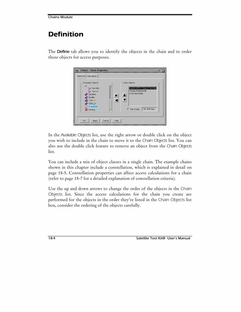
Chains Module
18-4 Satellite Tool Kit® User’s Manual
Definition
The Define tab allows you to identify the objects in the chain and to orderthose objects for access purposes.
In the Available Objects list, use the right arrow or double click on the objectyou wish to include in the chain to move it to the Chain Objects list. You canalso use the double click feature to remove an object from the Chain Objectslist.
You can include a mix of object classes in a single chain. The example chainsshown in this chapter include a constellation, which is explained in detail onpage 18-5. Constellation properties can affect access calculations for a chain(refer to page 18-7 for a detailed explanation of constellation criteria).
Use the up and down arrows to change the order of the objects in the ChainObjects list. Since the access calculations for the chain you create areperformed for the objects in the order they’re listed in the Chain Objects listbox, consider the ordering of the objects carefully.
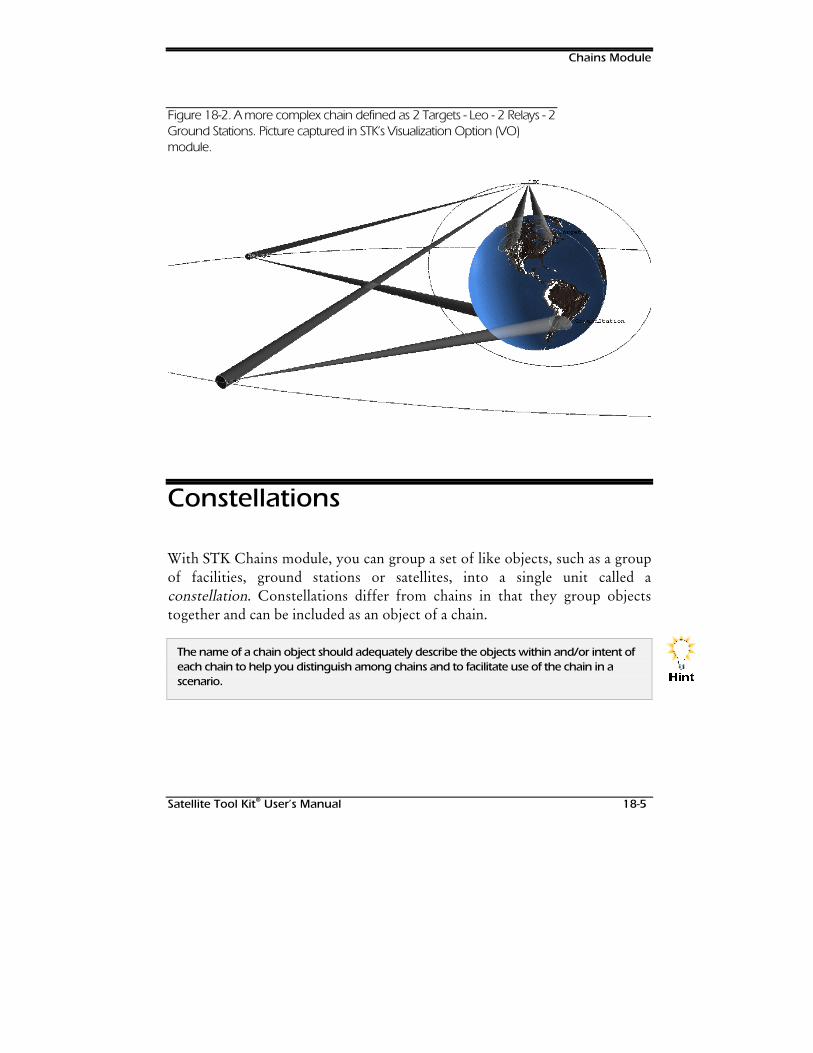
Chains Module
Satellite Tool Kit® User’s Manual 18-5
Figure 18-2. A more complex chain defined as 2 Targets - Leo - 2 Relays - 2Ground Stations. Picture captured in STK’s Visualization Option (VO)module.
Constellations
With STK Chains module, you can group a set of like objects, such as a groupof facilities, ground stations or satellites, into a single unit called aconstellation. Constellations differ from chains in that they group objectstogether and can be included as an object of a chain.
The name of a chain object should adequately describe the objects within and/or intent ofeach chain to help you distinguish among chains and to facilitate use of the chain in ascenario. +LQW
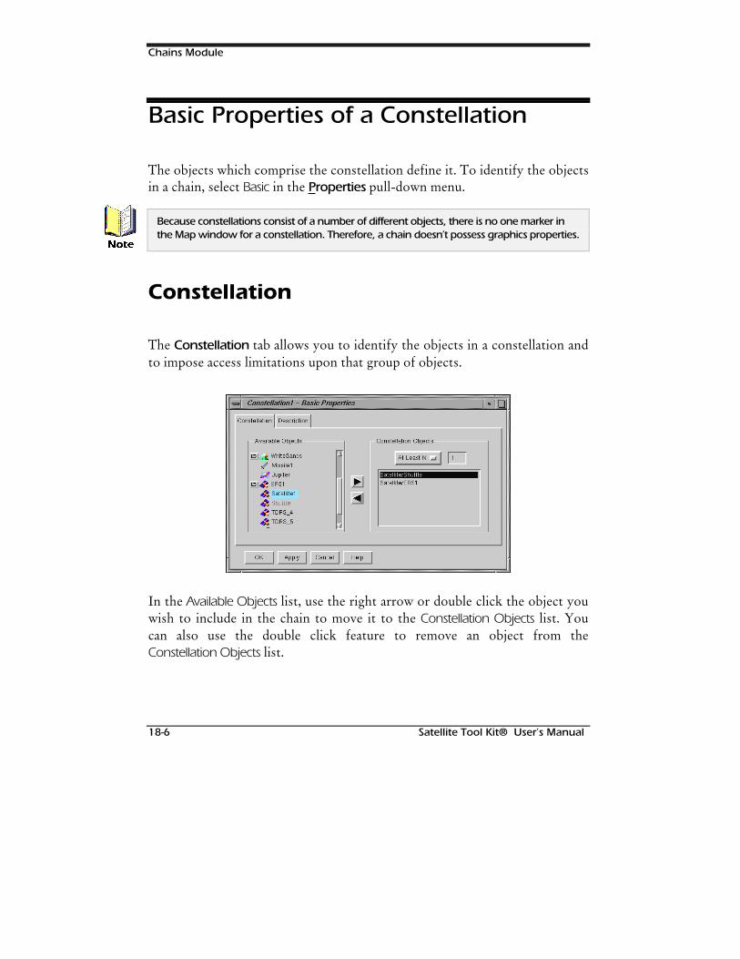
Chains Module
18-6 Satellite Tool Kit® User’s Manual
Basic Properties of a Constellation
The objects which comprise the constellation define it. To identify the objectsin a chain, select Basic in the Properties pull-down menu.
Because constellations consist of a number of different objects, there is no one marker inthe Map window for a constellation. Therefore, a chain doesn’t possess graphics properties.
Constellation
The Constellation tab allows you to identify the objects in a constellation andto impose access limitations upon that group of objects.
In the Available Objects list, use the right arrow or double click the object youwish to include in the chain to move it to the Constellation Objects list. Youcan also use the double click feature to remove an object from theConstellation Objects list.
1RWH
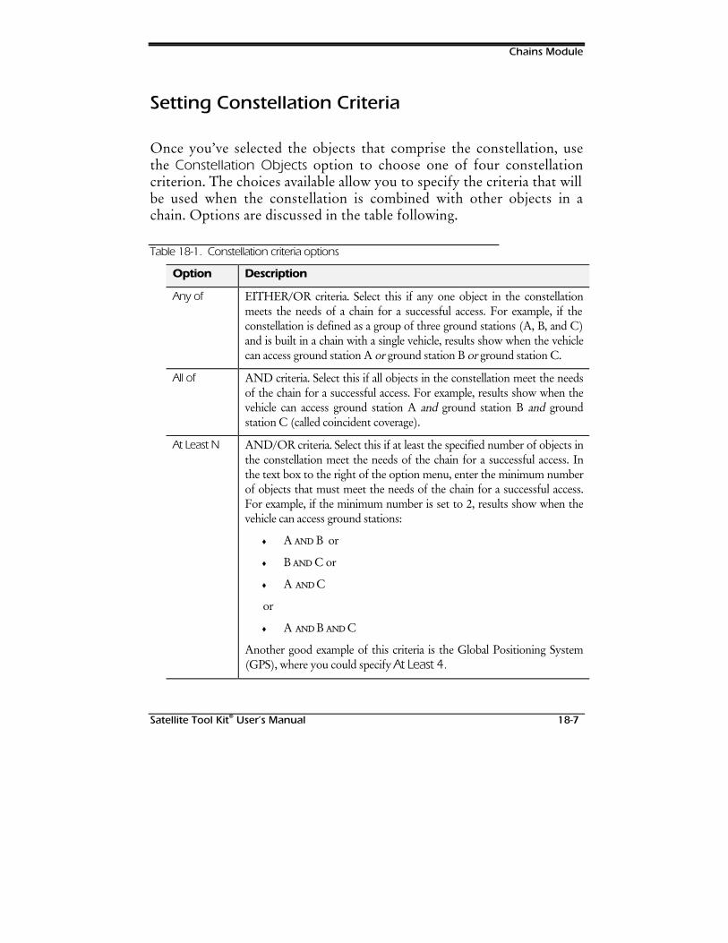
Chains Module
Satellite Tool Kit® User’s Manual 18-7
Setting Constellation Criteria
Once you’ve selected the objects that comprise the constellation, usethe Constellation Objects option to choose one of four constellationcriterion. The choices available allow you to specify the criteria that willbe used when the constellation is combined with other objects in achain. Options are discussed in the table following.
Table 18-1. Constellation criteria options
Option Description
Any of EITHER/OR criteria. Select this if any one object in the constellationmeets the needs of a chain for a successful access. For example, if theconstellation is defined as a group of three ground stations (A, B, and C)and is built in a chain with a single vehicle, results show when the vehiclecan access ground station A or ground station B or ground station C.
All of AND criteria. Select this if all objects in the constellation meet the needsof the chain for a successful access. For example, results show when thevehicle can access ground station A and ground station B and groundstation C (called coincident coverage).
At Least N AND/OR criteria. Select this if at least the specified number of objects inthe constellation meet the needs of the chain for a successful access. Inthe text box to the right of the option menu, enter the minimum numberof objects that must meet the needs of the chain for a successful access.For example, if the minimum number is set to 2, results show when thevehicle can access ground stations:
♦ A AND B or
♦ B AND C or
♦ A AND C
or
♦ A AND B AND C
Another good example of this criteria is the Global Positioning System(GPS), where you could specify At Least 4.
Chains Module
18-8 Satellite Tool Kit® User’s Manual
Option Description
Exactly N ONLY criteria. Select this if the exact specified number of objects in theconstellation meet the needs of a chain for a successful access. In the textbox to the right of the options menu, enter the exact number of objectsneeded to meet access requirements. For example, if the exact numberspecified is 2, results show when the vehicle can access both groundstations:
♦ A AANNDD B or
♦ B AANNDD C or
♦ A AANNDD C
♦ but NOT A AANNDD B AND C
You could also specify Exactly 0 to determine when no satellite is in theobject’s view.
Generating Reports for a Chain
A number of specialized reports are available for the chain object using theReport tool.
Individual Strand Access
A strand represents one possible access pathway through the chain. For achain defined by a series of individual objects, only a single strand is possible.In the case where one or more objects in the chain are constellations, multiplestrands are possible. Further, the constellation access conditions (i.e., ANYOF, ALL OF, AT LEAST N, EXACTLY N) determine the number of possiblestrands for a chain that includes constellation objects.
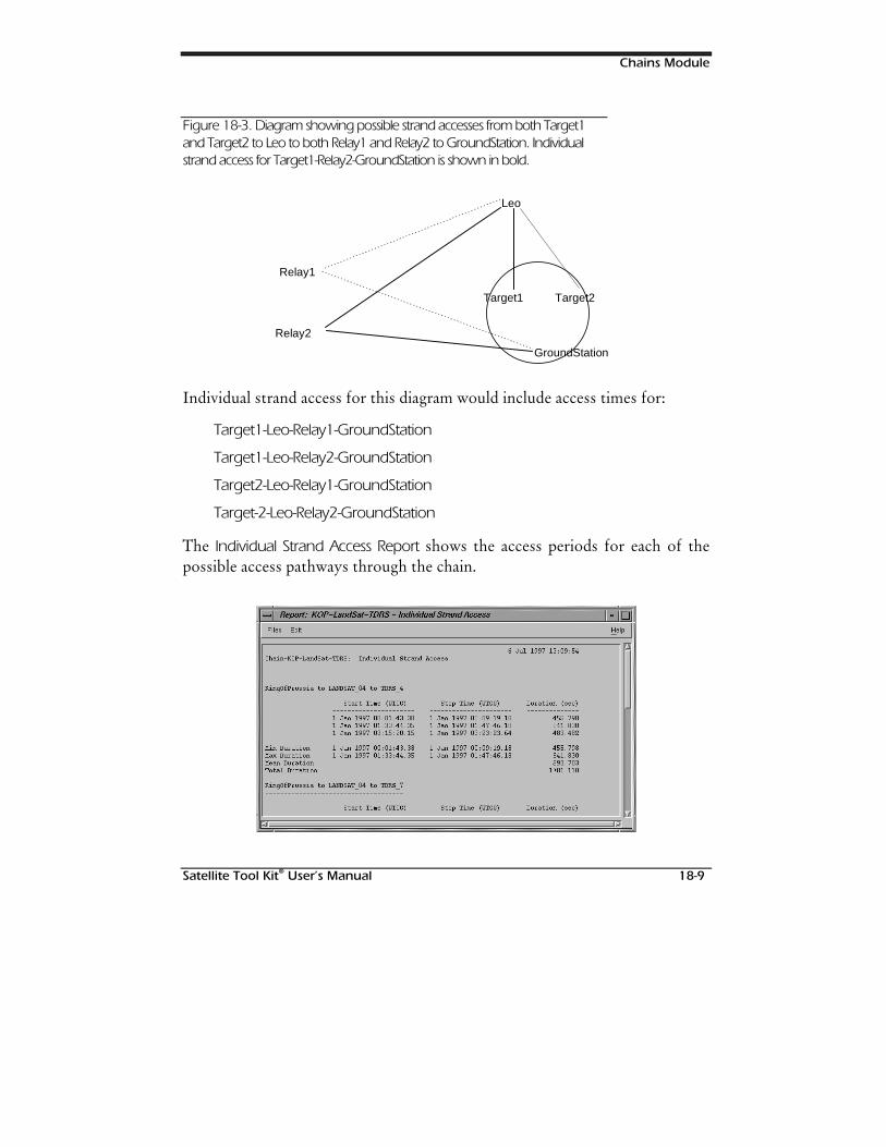
Chains Module
Satellite Tool Kit® User’s Manual 18-9
Figure 18-3. Diagram showing possible strand accesses from both Target1and Target2 to Leo to both Relay1 and Relay2 to GroundStation. Individualstrand access for Target1-Relay2-GroundStation is shown in bold.
Target2Target1
Leo
Relay1
Relay2
GroundStation
Individual strand access for this diagram would include access times for:
Target1-Leo-Relay1-GroundStation
Target1-Leo-Relay2-GroundStation
Target2-Leo-Relay1-GroundStation
Target-2-Leo-Relay2-GroundStation
The Individual Strand Access Report shows the access periods for each of thepossible access pathways through the chain.
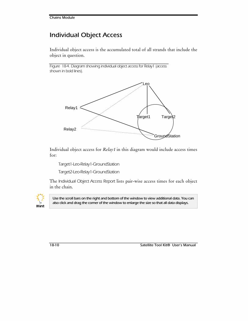
Chains Module
18-10 Satellite Tool Kit® User’s Manual
Individual Object Access
Individual object access is the accumulated total of all strands that include theobject in question.
Figure 18-4. Diagram showing individual object access for Relay1 (accessshown in bold lines).
Target2Target1
Leo
Relay1
Relay2
GroundStation
Individual object access for Relay1 in this diagram would include access timesfor:
Target1-Leo-Relay1-GroundStation
Target2-Leo-Relay1-GroundStation
The Individual Object Access Report lists pair-wise access times for each objectin the chain.
Use the scroll bars on the right and bottom of the window to view additional data. You canalso click and drag the corner of the window to enlarge the size so that all data displays.
+LQW
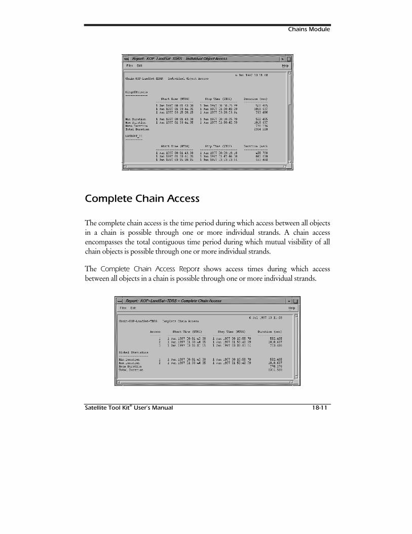
Chains Module
Satellite Tool Kit® User’s Manual 18-11
Complete Chain Access
The complete chain access is the time period during which access between all objectsin a chain is possible through one or more individual strands. A chain accessencompasses the total contiguous time period during which mutual visibility of allchain objects is possible through one or more individual strands.
The Complete Chain Access Reportt shows access times during which accessbetween all objects in a chain is possible through one or more individual strands.
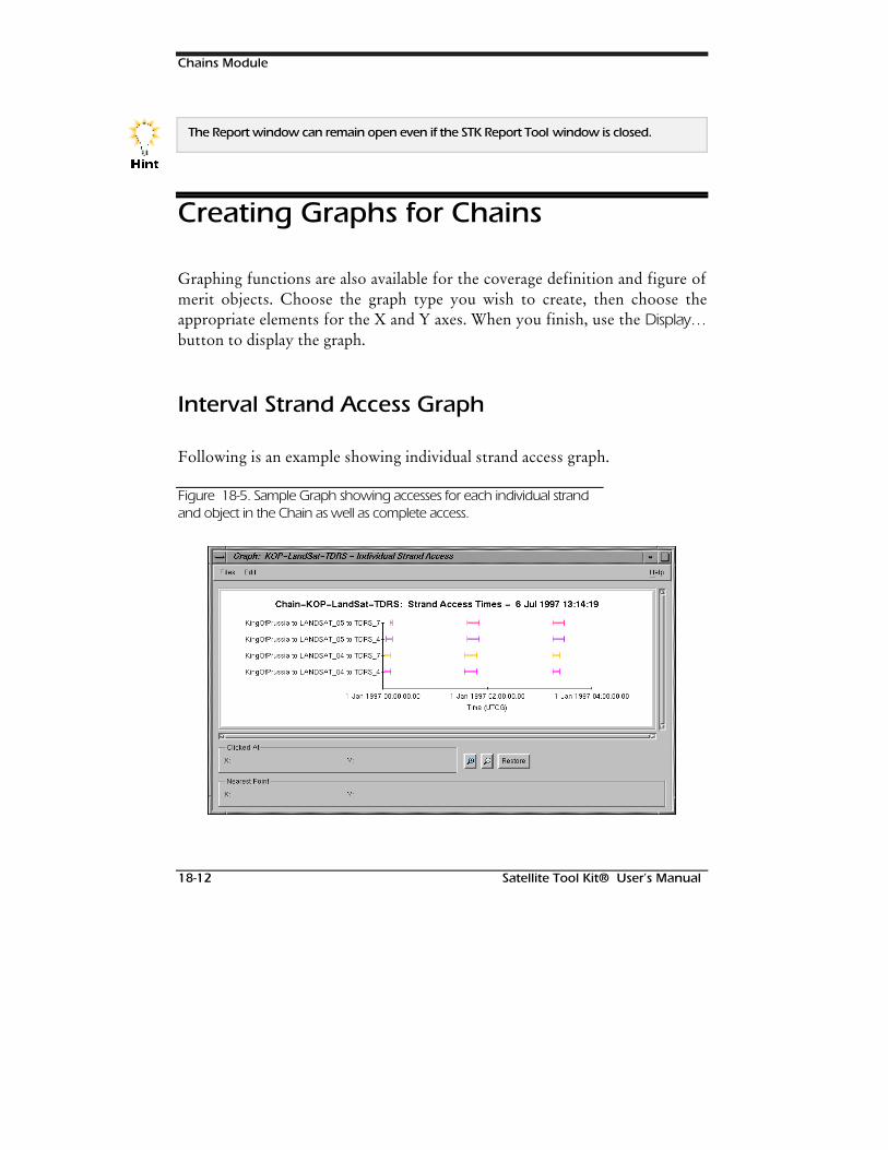
Chains Module
18-12 Satellite Tool Kit® User’s Manual
The Report window can remain open even if the STK Report Tool window is closed.
Creating Graphs for Chains
Graphing functions are also available for the coverage definition and figure ofmerit objects. Choose the graph type you wish to create, then choose theappropriate elements for the X and Y axes. When you finish, use the Display…button to display the graph.
Interval Strand Access Graph
Following is an example showing individual strand access graph.
Figure 18-5. Sample Graph showing accesses for each individual strandand object in the Chain as well as complete access.
+LQW
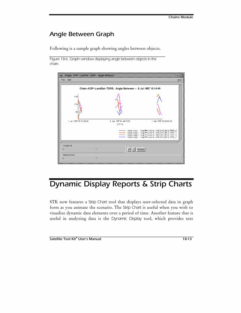
Chains Module
Satellite Tool Kit® User’s Manual 18-13
Angle Between Graph
Following is a sample graph showing angles between objects.
Figure 18-6. Graph window displaying angle between objects in thechain.
Dynamic Display Reports & Strip Charts
STK now features a Strip Chart tool that displays user-selected data in graphform as you animate the scenario. The Strip Chart is useful when you wish tovisualize dynamic data elements over a period of time. Another feature that isuseful in analyzing data is the Dynamic Display tool, which provides text

Chains Module
18-14 Satellite Tool Kit® User’s Manual
updates during animation so that you can view changes to selected elementsover a period of time.
For further information on Dynamic Displays and Strip Charts, see Chapters 15and 16 of this manual.
Satellite Tool Kit® A-1
APPENDIX A
GLOSSARY OF TERMS
Accelerator KeysKeys that speed up access to an action performedin STK. Identified by an underlined letter in theoption’s name or a key combination appearing tothe right of the option’s name in a pull-downmenu.
AccessThe geometric and temporal relationships betweenobjects that meet or exceed the constraints on theobjects, so that some task requiring both objectscan be performed.
AitoffSee Hammer-Aitoff.
AltitudeThe distance from an object to the surface of thecentral body measured positive along an outwardnormal to the central body surface.
Angle UnitSpecifies the measure of unit to be used whenreferring to angles. Options are degrees andradians.
AnimateThe process of displaying the movement of objectswithin a scenario on the map for a specified periodof time.
AnimationA Basic Properties tab that allows the user to setthe animation’s start time, end time/loop time,time step/x real-time/real-time, and refreshdelta/high speed.
Apparent PositionRefers to the viewed position of the object fromthe observer at a given time, which takes intoaccount the light time delay and aberrations.
ApplicationContains the scenario and all objects within thescenario. Basic Properties can be set at theapplication level.
ApoapsisThe point of an elliptical orbit that is farthest awayfrom the gravitational center of the systemconsisting of the primary body and the satellite(called the apogee in Earth-based systems).
ApogeeThe point in the satellite’s orbit that is farthestfrom the gravitational center of the Earth.
Apogee AltitudeAltitude of the apogee of an orbit where apogee isdefined as the point in the orbit which is farthestfrom the center of the central body.
Apogee Kick Motor (AKM)A motor used once during the lifetime of ageostationary satellite to provide the large delta-vrequired to turn a highly elliptical orbit withapogee at the geostationary altitude into a circular,geostationary orbit. Apogee Kick Motors areneeded because many launchers are not abledeliver a satellite into geostationary orbit. (theRussian Proton launcher is an exception to thisrule.)
Glossary of Terms
A-2 Satellite Tool Kit®
ApsisOne of the extreme end points of the major axis ofan elliptical orbit, such as the apogee or perigee.
Area TargetDefined geographical region of interest on theground.
Argument of PerigeeThe angle from the ascending node to the perigeedirection measured in the orbit plane and in thedirection of the object’s motion.
Ascending NodeThe point where the satellite passes through theinertial equatorial plane moving from south tonorth.
Atmospheric DragA retarding force acting on a satellite within theEarth's atmosphere. At altitudes below 160 km,the atmosphere causes a satellite’s orbit to decay(fall back to Earth) within a few revolutions. Ataltitudes above 700 km, drag has hardly anyinfluence.
AttitudeThe orientation of the three principal axes of anobject relative to a reference coordinate system.Also, [Vehicle:Basic Properties] allows the user tospecify the static or dynamic orientation of avehicle.
Auto Save[Application:Basic Properties] Allows the user tospecify the directory path and time intervals to beused when saving the scenario, activate or disableautomatic saving of work completed at thespecified intervals, perform a quick save of thescenario, and specify whether vehicle ephemerisshould be saved during an Auto Save or QuickSave.
AzimuthThe arc of the horizon measured clockwise fromnorth from 0° to 360°.
Azimuth AngleAzimuth is measured in the plane perpendicular tonadir from the projection of the velocity vector tothe projection of the relative position vector. Thisangle is measured in a positive manner accordingto the right-hand rule about the nadir vector.
Azimuth Rate
The time rate of change of the azimuth angle,usually expressed in degrees per second or radiansper second.
Azimuthal EquidistantA Map projection type that is mathematically
based on a planet tangent to the Earth. Spacing ofthe parallels is uniform.
B1950Standard epoch defined as the beginning of theBesselian year 1950 (when the longitude of themean Sun is 280.0° measured from the meanequinox) and corresponds to 31 December 194922:09:07.2 or JD 2433282.423.
Basic Properties[Properties menu] Properties menu option foreach object in STK, including a scenario. BasicProperties of an object define the object’sparameters and special features
BoresightThe electromagnetic axis of an antenna thatdefines the direction in which the antenna ispointing.
Browser WindowDisplays the classes and instances of all objectswithin the STK application. It enables you tocontrol the information being displayed. At thetop of the window are four pull-down menus:Files, Properties, Tools and Help. In the lowerportion of the window is a group of iconsrepresenting each of the object classes available inSTK.

Glossary of Terms
Satellite Tool Kit® A-3
Cartesian ElementsSpecify an orbit by three position elements andthree velocity elements in a rectangular coordinatesystem.
Check BoxAllows the user to flip between two oppositeconditions. When a check box displays a checkmark, the option is ON.
ClassObjects in STK are arranged in classes that sharecommon attributes and traits. There are eightclasses in STK: scenario, vehicle, facility, target,area target, planet, star, sensor
Classical ElementsAlso known as Keplerian elements. These elementsspecify an orbit by its size, shape, and three-dimensional orientation in inertial space.
Clock AngleAn angle measured in the plane perpendicular toan antenna boresight from the up vector for thesensor.
Close[Files menu] Close a scenario without exitingSTK. When you close a scenario, the Map windowdisappears.
ConicA shape defined as a cross-section of a rightcircular cone. Cross-sections at various anglesthrough the cone generate circles, ellipses,parabolas, and hyperbolas. Also a type of sensordefined through the specification of an origin andaxis directions. The components of vectors specifythe orientation of the vectors within a specificcoordinate system.
ConstraintA boundary condition placed on a parameter thatlimits its validity to a subset of its original range.
Constraints Properties[Properties menu] This window allows the user tospecify the constraints that have been imposedupon the selected object.
Coordinate TypeSet of orbital elements. Some coordinate sets aremore useful in certain situations than others.
Coordinate SystemA system in which positions are specified by a setof coordinates.
CoverageThe area of the Earth’s surface visible to anorbiting spacecraft during one or more orbits. Acoverage pattern is the sequence of coverage overan extended period of time.
Date FormatSpecifies the format to be used when referring tocalendar dates. Available formats include: UTCGregorian, UTC Julian, Local Julian, LocalGregorian, Epoch Seconds.
DeclinationAn angle in a meridian, measured northward fromthe ecliptic to a line running from the Earth’scenter to a given celestial object.
Delaunay ElementsA set of canonical angle-action variablescommonly used in general perturbation theories.An orbit is defined by a set of conjugate angle-action pairs.
Delta-vThe speed change needed for a change in orbitparameters. The direction and size of the delta-vdetermines which orbit parameters are mostaffected, and to what extent. For instance, a delta-v orthogonal to the orbit plane at the time itcrosses the ascending or descending node resultsin an inclination change. The latter maneuverrequires a relatively large amount of propellant;tight inclination control therefore limits thelifetime of a satellite in orbit considerably.
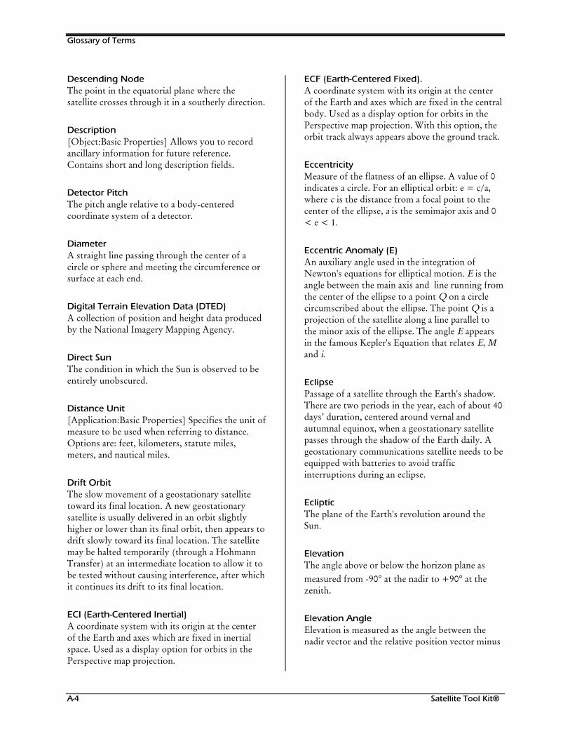
Glossary of Terms
A-4 Satellite Tool Kit®
Descending NodeThe point in the equatorial plane where thesatellite crosses through it in a southerly direction.
Description[Object:Basic Properties] Allows you to recordancillary information for future reference.Contains short and long description fields.
Detector PitchThe pitch angle relative to a body-centeredcoordinate system of a detector.
DiameterA straight line passing through the center of acircle or sphere and meeting the circumference orsurface at each end.
Digital Terrain Elevation Data (DTED)A collection of position and height data producedby the National Imagery Mapping Agency.
Direct SunThe condition in which the Sun is observed to beentirely unobscured.
Distance Unit[Application:Basic Properties] Specifies the unit ofmeasure to be used when referring to distance.Options are: feet, kilometers, statute miles,meters, and nautical miles.
Drift OrbitThe slow movement of a geostationary satellitetoward its final location. A new geostationarysatellite is usually delivered in an orbit slightlyhigher or lower than its final orbit, then appears todrift slowly toward its final location. The satellitemay be halted temporarily (through a HohmannTransfer) at an intermediate location to allow it tobe tested without causing interference, after whichit continues its drift to its final location.
ECI (Earth-Centered Inertial)A coordinate system with its origin at the centerof the Earth and axes which are fixed in inertialspace. Used as a display option for orbits in thePerspective map projection.
ECF (Earth-Centered Fixed).A coordinate system with its origin at the centerof the Earth and axes which are fixed in the centralbody. Used as a display option for orbits in thePerspective map projection. With this option, theorbit track always appears above the ground track.
EccentricityMeasure of the flatness of an ellipse. A value of 0indicates a circle. For an elliptical orbit: e = c/a,where c is the distance from a focal point to thecenter of the ellipse, a is the semimajor axis and 0< e < 1.
Eccentric Anomaly (E)An auxiliary angle used in the integration ofNewton's equations for elliptical motion. E is theangle between the main axis and line running fromthe center of the ellipse to a point Q on a circlecircumscribed about the ellipse. The point Q is aprojection of the satellite along a line parallel tothe minor axis of the ellipse. The angle E appearsin the famous Kepler's Equation that relates E, Mand i.
EclipsePassage of a satellite through the Earth's shadow.There are two periods in the year, each of about 40days’ duration, centered around vernal andautumnal equinox, when a geostationary satellitepasses through the shadow of the Earth daily. Ageostationary communications satellite needs to beequipped with batteries to avoid trafficinterruptions during an eclipse.
EclipticThe plane of the Earth's revolution around theSun.
ElevationThe angle above or below the horizon plane asmeasured from -90° at the nadir to +90° at thezenith.
Elevation AngleElevation is measured as the angle between thenadir vector and the relative position vector minus
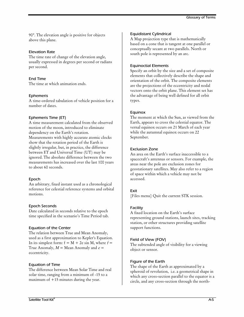
Glossary of Terms
Satellite Tool Kit® A-5
90°. The elevation angle is positive for objectsabove this plane.
Elevation RateThe time rate of change of the elevation angle,usually expressed in degrees per second or radiansper second.
End TimeThe time at which animation ends.
EphemerisA time-ordered tabulation of vehicle position for anumber of dates.
Ephemeris Time (ET)A time measurement calculated from the observedmotion of the moon, introduced to eliminatedependency on the Earth’s rotation.Measurements with highly accurate atomic clocksshow that the rotation period of the Earth isslightly irregular, but, in practice, the differencebetween ET and Universal Time (UT) may beignored. The absolute difference between the twomeasurements has increased over the last 100 yearsto about 60 seconds.
EpochAn arbitrary, fixed instant used as a chronologicalreference for celestial reference systems and orbitalmotions.
Epoch SecondsDate calculated in seconds relative to the epochtime specified in the scenario’s Time Period tab.
Equation of the CenterThe relation between True and Mean Anomaly,used as a first approximation to Kepler's Equation.In its simplest form: f = M + 2e sin M, where f =True Anomaly, M = Mean Anomaly and e =eccentricity.
Equation of TimeThe difference between Mean Solar Time and realsolar time, ranging from a minimum of -15 to amaximum of +15 minutes during the year.
Equidistant CylindricalA Map projection type that is mathematicallybased on a cone that is tangent at one parallel orconceptually secant at two parallels. North orsouth pole is represented by an arc.
Equinoctial ElementsSpecify an orbit by the size and a set of compositeelements that collectively describe the shape andorientation of the orbit. The composite elementsare the projections of the eccentricity and nodalvectors onto the orbit plane. This element set hasthe advantage of being well defined for all orbittypes.
EquinoxThe moment at which the Sun, as viewed from theEarth, appears to cross the celestial equator. Thevernal equinox occurs on 21 March of each yearwhile the autumnal equinox occurs on 22September.
Exclusion ZoneAn area on the Earth’s surface inaccessible to aspacecraft’s antennas or sensors. For example, theareas near the pole are exclusion zones forgeostationary satellites. May also refer to a regionof space within which a vehicle may not beaccessed.
Exit[Files menu] Quit the current STK session.
FacilityA fixed location on the Earth’s surfacerepresenting ground stations, launch sites, trackingstation, or other structures providing satellitesupport functions.
Field of View (FOV)The subtended angle of visibility for a viewingobject or sensor.
Figure of the EarthThe shape of the Earth as approximated by aspheroid of revolution, i.e. a geometrical shape inwhich any cross-section parallel to the equator is acircle, and any cross-section through the north-
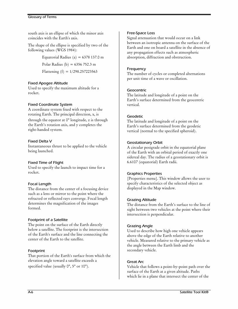
Glossary of Terms
A-6 Satellite Tool Kit®
south axis is an ellipse of which the minor axiscoincides with the Earth's axis.
The shape of the ellipse is specified by two of thefollowing values (WGS 1984):
Equatorial Radius (a) = 6378 137.0 m
Polar Radius (b) = 6356 752.3 m
Flattening (f) = 1/298.257223563
Fixed Apogee AltitudeUsed to specify the maximum altitude for arocket.
Fixed Coordinate SystemA coordinate system fixed with respect to therotating Earth. The principal direction, x, isthrough the equator at 0° longitude, z is throughthe Earth’s rotation axis, and y completes theright-handed system.
Fixed Delta VInstantaneous thrust to be applied to the vehiclebeing launched.
Fixed Time of FlightUsed to specify the launch to impact time for arocket.
Focal LengthThe distance from the center of a focusing devicesuch as a lens or mirror to the point where therefracted or reflected rays converge. Focal lengthdetermines the magnification of the imagesformed.
Footprint of a SatelliteThe point on the surface of the Earth directlybelow a satellite. The footprint is the intersectionof the Earth's surface and the line connecting thecenter of the Earth to the satellite.
FootprintThat portion of the Earth's surface from which theelevation angle toward a satellite exceeds aspecified value (usually 0°, 5° or 10°).
Free-Space LossSignal attenuation that would occur on a linkbetween an isotropic antenna on the surface of theEarth and one on board a satellite in the absence ofany propagation effects such as atmosphericabsorption, diffraction and obstruction.
FrequencyThe number of cycles or completed alternationsper unit time of a wave or oscillation.
GeocentricThe latitude and longitude of a point on theEarth’s surface determined from the geocentricvertical.
GeodeticThe latitude and longitude of a point on theEarth’s surface determined from the geodeticvertical (normal to the specified spheroid).
Geostationary OrbitA circular posigrade orbit in the equatorial planeof the Earth with an orbital period of exactly onesidereal day. The radius of a geostationary orbit is6.6107 (equatorial) Earth radii.
Graphics Properties[Properties menu]. This window allows the user tospecify characteristics of the selected object asdisplayed in the Map window.
Grazing AltitudeThe distance from the Earth’s surface to the line ofsight between two vehicles at the point where theirintersection is perpendicular.
Grazing AngleUsed to describe how high one vehicle appearsabove the edge of the Earth relative to anothervehicle. Measured relative to the primary vehicle asthe angle between the Earth limb and thesecondary vehicle.
Great ArcVehicle that follows a point-by-point path over thesurface of the Earth at a given altitude. Pathswhich lie in a plane that intersect the center of the
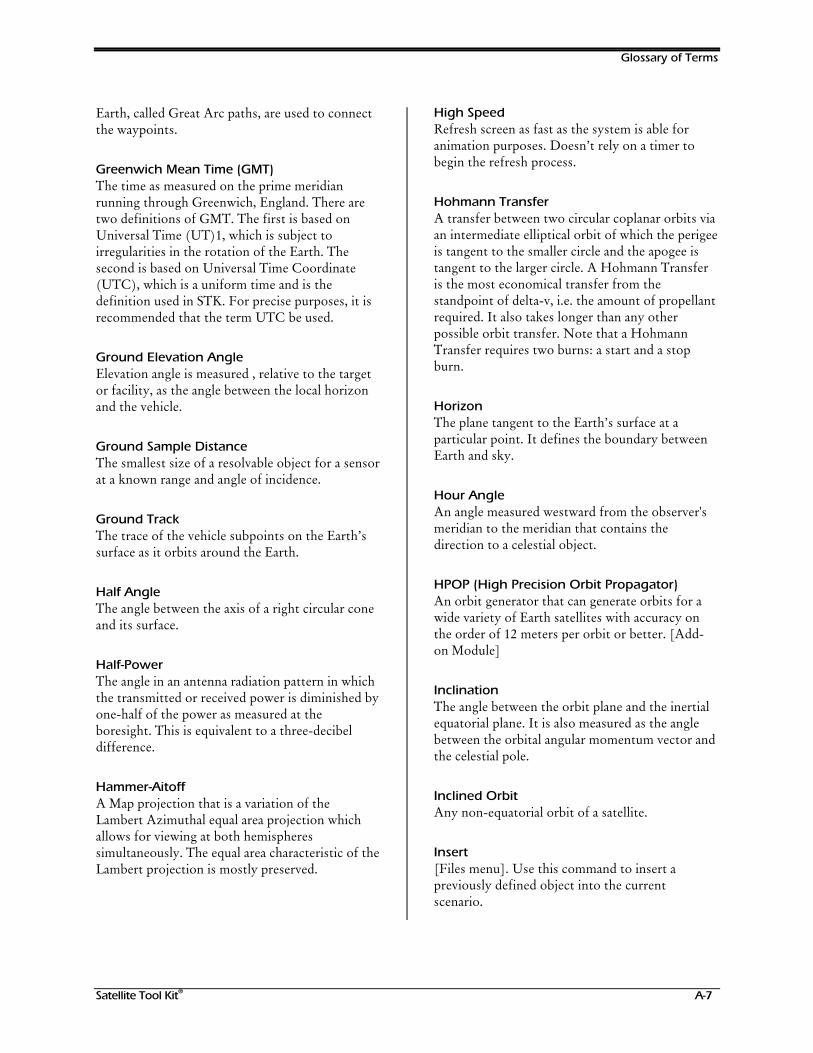
Glossary of Terms
Satellite Tool Kit® A-7
Earth, called Great Arc paths, are used to connectthe waypoints.
Greenwich Mean Time (GMT)The time as measured on the prime meridianrunning through Greenwich, England. There aretwo definitions of GMT. The first is based onUniversal Time (UT)1, which is subject toirregularities in the rotation of the Earth. Thesecond is based on Universal Time Coordinate(UTC), which is a uniform time and is thedefinition used in STK. For precise purposes, it isrecommended that the term UTC be used.
Ground Elevation AngleElevation angle is measured , relative to the targetor facility, as the angle between the local horizonand the vehicle.
Ground Sample DistanceThe smallest size of a resolvable object for a sensorat a known range and angle of incidence.
Ground TrackThe trace of the vehicle subpoints on the Earth’ssurface as it orbits around the Earth.
Half AngleThe angle between the axis of a right circular coneand its surface.
Half-PowerThe angle in an antenna radiation pattern in whichthe transmitted or received power is diminished byone-half of the power as measured at theboresight. This is equivalent to a three-decibeldifference.
Hammer-AitoffA Map projection that is a variation of theLambert Azimuthal equal area projection whichallows for viewing at both hemispheressimultaneously. The equal area characteristic of theLambert projection is mostly preserved.
High SpeedRefresh screen as fast as the system is able foranimation purposes. Doesn’t rely on a timer tobegin the refresh process.
Hohmann TransferA transfer between two circular coplanar orbits viaan intermediate elliptical orbit of which the perigeeis tangent to the smaller circle and the apogee istangent to the larger circle. A Hohmann Transferis the most economical transfer from thestandpoint of delta-v, i.e. the amount of propellantrequired. It also takes longer than any otherpossible orbit transfer. Note that a HohmannTransfer requires two burns: a start and a stopburn.
HorizonThe plane tangent to the Earth’s surface at aparticular point. It defines the boundary betweenEarth and sky.
Hour AngleAn angle measured westward from the observer'smeridian to the meridian that contains thedirection to a celestial object.
HPOP (High Precision Orbit Propagator)An orbit generator that can generate orbits for awide variety of Earth satellites with accuracy onthe order of 12 meters per orbit or better. [Add-on Module]
InclinationThe angle between the orbit plane and the inertialequatorial plane. It is also measured as the anglebetween the orbital angular momentum vector andthe celestial pole.
Inclined OrbitAny non-equatorial orbit of a satellite.
Insert[Files menu]. Use this command to insert apreviously defined object into the currentscenario.
Glossary of Terms
A-8 Satellite Tool Kit®
InstanceA specific occurrence of an object class. Forexample, the ERS1 vehicle is one instance of thevehicle class.
J2 PerturbationAn analytical orbit propagator that accounts forsecular variations in the orbital elements due to thefirst order Earth oblateness effects.
J4 PerturbationAn analytical orbit propagator that accounts forsecular variations in the orbital elements due tofirst and second order Earth oblateness effects.
J2000 Coordinate SystemSpecifies that X and Z axes point toward the meanvernal equinox and mean rotation axes of the Earthat January 1, 2000 at 12:00:00.00 UTC. J2000.0 =2000 January 1.5 = JD 2451545.0 TDB(Barycentric Dynamic Time).
Julian Date (JD)The sequential day count reckoned consecutivelybeginning on 1 January 4713 BC. The Julian Datefor 1 January 1990 was 2,446,892.
Keplerian ElementsA set of six parameters which together describethe shape and orientation of an elliptical orbitaround the Earth, as well as the position of asatellite in that orbit at a given epoch. The usualelements are: Right Ascension of the AscendingNode, Argument of the Perigee, Mean Anomaly,Semi-Major Axis, Inclination and Eccentricity.
Kepler's EquationAn equation that relates Mean Anomaly (M),Eccentric Anomaly (E) and Eccentricity (e),namely:
M = E - e sin E
The equation is used to calculate E for given Mand e. It is possible to calculate the True Anomalyfrom E.
Keyboard AcceleratorsSee Accelerator Keys.
LatitudeThe angular distance north or south from theequator of a point on the Earth’s surface,expressed in degrees.
Line of SightGeometric direction in which two objects havedirect visibility of each other.
Local Apparent TimeThe hour angle between an observer’s localmeridian and the meridian passing through thetrue Sun. A Sundial reads local apparent time.Using this time reference, the Sun is at its highestelevation at noon.
Local Satellite TimeThe time corresponding to a satellite’s position inits orbit relative to the Sun. When the satellitecrosses the projection of the Sun vector onto theorbit plane on the side of the orbit nearest the Sun,it is satellite noon. When the satellite crosses theprojection of the Sun vector onto the orbit planeon the side of the orbit farthest from the Sun, it issatellite midnight.
Local GregorianLocal time zone date and time expressed instandard Gregorian format (1 Nov 199700:00:00.0000).
Local JulianLocal time zone date and time expressed in day-of-year format (306/97 00:00:00.0000).
LongitudeAngular distance along the equator from theGreenwich meridian to the point of interest.Although the convention is to measure this anglefrom 0° to 360° eastward, longitudes are oftenexpressed -180° to +180° or 180° West to 180°East.
Loop TimeTime at which animation loops back to the StartTime specified.
Glossary of Terms
Satellite Tool Kit® A-9
Lunar Exclusion AngleMinimum angle between the line of sight from theobject to the object of interest and the line of sightfrom the object to the Moon for which access isconsidered valid.
Major Axis of an EllipseThe longest diameter of the ellipse, which passesthrough the center and both focal points.
MagnitudeThe brightness of a celestial body as expressed ona logarithmic scale. Magnitude increases for fainterobjects so that a magnitude 1 object is brighterthan a magnitude 2 object.
Map Attributes>Scenario: Graphics Properties] Controls thedisplay of data such as orbit paths, object names,ground tracks, and other satellite data. Attributesalso controls the display of the tool bar at the topof the Map window and selection options.
Map BackgroundScenario: Graphics Properties] Controls thedisplay of background image files or “texture” todisplay in the Map window.
Map DetailsScenario: Graphics Properties] Controls thedisplay of land mass and other map features suchas the display of latitude and longitude lines in thebackground and the image resolution of the map.
Map ProjectionControls the way in which the three-dimensional(3-D) globe is presented in the Map window.
MapMaps provide a geographic reference for ascenario’s objects. The objects within a scenarioare related by time to a map.
Mass UnitSpecifies the unit of measure to be used whenreferring to mass. Two options are available:kilograms and pounds mass (not weight).
Mean AnomalyThe angle measured from perigee of a hypotheticalbody moving with a uniform speed that is equal tothe mean motion. It is the product of the meanmotion of the spacecraft and the interval of timesince it passed perigee. T is the orbital period and tis the time past periapsis:
Mt
Tradians=
⋅2π( )
Mean Solar Time or Universal Time (UT)Time measured with reference to the motion of afictitious body called the Mean Sun, which movesat a constant rate. Another way to state thisassumption is that the Earth moves in a circularorbit around the sun, and that the axis of rotationis perpendicular to the orbital plane (ecliptic). Thetime interval between two meridian crossings ofthe Mean Sun is exactly one solar day. Due to thecombined effects of the eccentricity of the Earth'sorbit and the tilt of the Earth’s rotation axis, thereal sun arrives at our local meridian a little early atcertain times of the year, and a little late at othertimes. The difference between real solar time andmean solar time is called the Equation of Time.
Mean Equinox True Equator CoordinateSystemSpecifies that the X and Z axes point toward themean vernal equinox and true rotation axis of theOrbit Epoch date specified.
Mean MotionThe uniform rate of the satellite in a circular orbitof the same period, typically expressed as degreesor radians per second, or as revolutions per day. Tis the orbital Period:
nT
radians=2π
( / sec)
Mean Motion DotThe time rate of change of mean motion indicatingthe degree to which perturbation forces acting onthe satellite are changing the size of the orbit.
Glossary of Terms
A-10 Satellite Tool Kit®
Mean of Date Coordinate SystemAn inertial coordinate frame in which the directionof the X axis is defined by the mean vernalequinox and the Z axis is defined by the mean spinaxis of the Earth at the time of the state vector.The term Mean indicates that precession isaccounted for but nutation is not.
Mean of Epoch Coordinate SystemAn inertial coordinate frame in which the directionof the X axis is defined by the mean vernalequinox and the Z axis is defined by the mean spinaxis of the Earth at a user-specified epoch. Theterm Mean indicates that precession is accountedfor but nutation is not.
MercatorProjection can be thought of as beingmathematically based on a cylinder tangent at theequator. Any straight line is a constant-azimuthline, which is also called a loxodrome or rhumbline. The north and south poles cannot be shownin this rectangular projection since they are atinfinite distance.
Meta KeyA special keyboard key that typically has a uniqueshape (such as the diamond on the Sunworkstation Meta key) or a unique word (such asthe Error! Not a valid filename. key on the Decand IBM workstation). Used in key combinationsfor accelerator keys.
MillerRectangular projection constructed to provide analternative to the Mercator projection. The twoprojections are similar near the equator but theMiler projection avoids some of the exaggerationin scale near the poles.
Mixed SphericalA variation of the spherical coordinate system thatcombines Earth-fixed position parameters withinertial velocity parameters.
MollweideEqual and pseudo-cylindrical projection showingthe Earth in an ellipse with the equator twice aslong as the map’s actual meridian.
Motion Dot DotThe second derivative of mean motion and firstderivative of motion dot. This quantity indicatesthe degree to which the change in the size of theorbit is accelerating due to perturbative effects onthe spacecraft.
MSGP4 PropagatorUsed with two-line mean element sets. ConsidersEarth oblateness, solar and lunar gravitationaleffects, and resonance effects using a mean dragmodel.
NadirThe point on the celestial sphere directly beneath agiven position or observer and diametricallyopposite the zenith. Also the direction from anobject towards the center of the central body.
Node RotationA rotation of the orbital plane caused by the non-spherical shape (oblateness) of the Earth. Thisprecessional motion is similar to that of a simple top: thenormal to the orbital plane sweeps out a cone shapedsurface in space with a semi-vertex angle equal to theinclination i. As the orbit precesses, the line ofintersection of the equator and the orbital plane (the lineof nodes) rotates westward for a posigrade orbit andeastward for a retrograde orbit.
ObjectAn STK component capable of being manipulated.In STK, objects are scenarios, vehicles, facilities,targets, area targets, stars, planets, and sensors.
Open[Files menu] Insert a previously saved scenariointo the current STK session. Only one scenariocan be open at any given time.
Glossary of Terms
Satellite Tool Kit® A-11
Options MenuThese menus allow the user to select one and onlyone item from a list that appears when you clickand hold the associated menu button.
OrbitThe gravitationally bound path followed by anobject around a celestial body.
Orbital ElementsThe set of parameters that describe the size, shape,and orientation of an orbit in inertial space.
OrthographicProjection is geometrically based on a planetangent to the Earth. The point of projection is atinfinity. Directions from the center of the mapprojection are true.
Osculating OrbitThe orbit along which a satellite would move if allperturbing accelerations were removed at aparticular time. At that time, or Epoch, theosculating and true orbits are in contact. It is theosculating orbit – not the true, perturbed orbit –for which the Keplerian elements are used.
ParallaxThe apparent displacement of an observed objectdue to a change in the position of the observer.
Pass Break[Vehicle:Basic Properties] The point at which apass is considered to commence. Either theascending or descending node of the orbit.
PassesA pass is a complete orbit of a satellite around theEarth between successive node crossings.
Path[Vehicle:Basic Properties] The route along which anobject moves.
PenumbraThat portion of a shadow in which the Sun is seenas partially obscured.
PeriapsisThe point in an elliptical orbit that is closest to thegravitational center of the system comprising theprimary body and the satellite. In Earth-basedsystems, the periapsis is called the perigee.
PerigeeThe point in the orbit of a satellite orbiting theEarth that is closest to the gravitational center ofthe Earth.
Perigee AltitudeAltitude of the perigee of an orbit where perigee isdefined as the point in the orbit which is closest tothe center of the central body..
Period (T)The time required for a satellite to complete onerevolution around the center of gravity.
PersistenceLength of time a sensor’s footprint remains visible.
PerspectiveProjection of the Earth as a sphere from a user-specified viewing altitude.
PerturbationDeviation of a satellite from true elliptical motion,caused by disturbing accelerations due to the non-spherical shape of the Earth, influence of sun andmoon, drag and solar radiation pressure.
Pitch A rotation about the Y axis of a referencecoordinate system. This reference coordinatesystem can be a local system moving with theobject, a body-fixed coordinate system or aninertial coordinate system. Pitch is defined relativeto the inertial coordinate system within STK.
PlanetA solar system object that orbits around the Sun. Theword planet originates from the Latin for “wanderer.”
Glossary of Terms
A-12 Satellite Tool Kit®
Posigrade OrbitAn orbit in which the projection of the satellite'sposition on the Earth's equatorial plane revolves in thedirection of the rotation of the Earth. The inclinationof a posigrade orbit is less than 90 degrees.
PrecessionRotation of the orbital plane caused by the non-spherical shape (oblateness) of the Earth.Precessional motion is similar to that of a simpletop: the normal to the equatorial plane sweeps outa cone shaped surface in space with a semi-vertexangle equal to the inclination i. As the orbitprecesses, the line of intersection of the equatorand the orbital plane (line of nodes) rotateswestward for a posigrade orbit and eastward for aretrograde orbit.
Print Setup[Files menu] Set print parameters such asorientation, width/height, layout, output device,color mode, background, and file format.
Properties MenuPull-Down Menu that allows the user to set basic,graphics, and constraints properties for the selectedobject.
Pull-down MenuClick the menu of your choice in the menu bar at thetop of the Browser window to display pull-downmenus of available options. Four pull-down menus areavailable: Files, Properties, Tools, and Help.
Radio ButtonDiamond-shaped button that allow the user toselect one and only one item in a group of radiobuttons.
RangeThe linear distance between two points.
Range RateThe component of the spacecraft velocity in the radialdirection either toward or away from the observer.
RateA change in some quantity over time.
Real-TimeRun animation in real-time in accordance with theuser’s on-board real-time clock.
Rectangular Coordinate SystemA coordinate system in which positions arespecified by distances from the origin along thethree mutually orthogonal axes.
Refresh DeltaTime lapse between refresh updates. Actual refresh deltais limited by the minimum time necessary to redraw thescreen and varies with processor performance, graphicshardware options, and scenario complexity.
Remove[Files menu] Use this command to remove an objectfrom the current scenario.
Resolution[Sensor:Basic/Constraints Properties] The degree towhich two closely spaced objects can be distinguished asseparate. Resolution increases with increasing aperture;larger antenna and larger telescopes have better resolutionthan smaller ones.
Retrograde OrbitAn orbit in which the projection of the satellite'sposition on the Earth's equatorial plane revolves inthe direction opposite to that of the rotation ofthe Earth. The inclination of a retrograde orbit isgreater than 90 degrees.
Right AscensionAngle measured in the inertial equatorial planefrom the inertial X axis in a right-handed senseabout the inertial Z axis.
Right Ascension of Ascending Node (RAAN)The angle measured in the inertial equatorial plane fromthe inertial X axis to the ascending node of the satellite’sorbit in a right-handed sense about the inertial Z axis.
RocketDefines a vehicle following an elliptical path thatbegins and ends at the Earth’s surface.
Glossary of Terms
Satellite Tool Kit® A-13
RollA rotation about the X axis of a referencecoordinate system. This coordinate system can bea local system moving with the object, a body-fixed coordinate system or an inertial coordinatesystem. Roll is defined relative to the inertialcoordinate system in STK.
Round-trip Delay TimeThe time required for a signal to travel from an Earthstation via a satellite to another Earth station(approximately 250 milliseconds for a geostationarysatellite).
Save As[Files menu] Use this command to save the currentobject under anew name.
Save[Files menu] Use this command to overwrite theoriginal object file so that it includes any changesmade since last saved.
ScenarioThe highest-level object within STK. Scenarioscontain other objects and becomes the outline fora proposed series of events that can be visualized.
Semimajor AxisHalf the distance between the two most distantpoints on an ellipse. For a circle, the semimajoraxis is the same as the radius of the circle.
SensorsBeam of some shape that points in a particulardirection. Sensors can represent transmitting,receiving, or sensing devices with associatedattributes and/or constraints. They can also beattached to a vehicle, facility, or target. They canalso be used to define areas such as a satellite’sfield of view of constraint, or areas such as aminimum elevation for a target in a valley.
Sidereal TimeThe time required for the Earth to rotate once onits axis relative to the stars, equal to 23h 56m 4s ofordinary mean solar time. A sidereal day consistsof 24 sidereal hours and begins when the Vernal
Equinox crosses the Greenwich meridian. Siderealtime is therefore equal to the Hour Angle of theVernal Equinox.
SinusoidalProjection is mathematically based on a cylindertangent on the equator. May have several centralmeridians.
Solar Beta AngleThe signed angle of the vector to the Sun relativeto the orbital plane. The signed angle is positivewhen the vector to the Sun is in the direction ofthe orbit normal. The orbit normal is parallel tothe orbital angular momentum vector, which isdefined as the cross-product of the inertialposition and velocity vector.
Solar Exclusion AngleMinimum angle between the line of sight from theobject to the object of interest and the line of sightfrom the object to the Sun for which access isconsidered valid.
Spherical Coordinate SystemA coordinate system in which positions arespecified as a radial distance from the origin andtwo angles relative to a fundamental plane.
Spin OffsetEstablishes the spin angle from some referencepoint at epoch.
SSC (Space Surveillance Catalog) NumberNumber assigned to satellites for purposes ofidentification.
StarA fixed point on the celestial sphere representingmembers of the solar neighborhood andcharacterized by their position and brightness.
Start TimeParameter that specifies when a specified functionis to begin.
Glossary of Terms
A-14 Satellite Tool Kit®
Status AreaArea located along the bottom of the Map windowthat displays latitude and longitude values,animation time, and status messages (such aspaused and inactive).
Step CountAlso referred to as Step Size. For orbitpropagation, step size is the time step used incalculating ephemeris points. In animation, stepsize determines how much time passes betweeneach picture update.
Step SizeSee Step Count.
StereographicProjection is geometrically projected onto a plane.The point of projection is on the surface of thesphere opposite the point of tangency. Directionsfrom the center of the projection are true.
.stkrc File[PC STK Run Control File] File that identifies theSTK database and STK home directories as well ascertain defaults set for the STK session.
.stkrc3 File[UNIX STK Run Control File] File that identifiesthe STK database and STK home directories aswell as certain defaults set for the STK session.
Stop TimeParameter that specifies when a specified functionis to end.
Subsolar PointThe point on the Earth directly below the Sun.
Sun Elevation AngleThe elevation of the Sun relative to the selectedobject.
Sun Lighting[Vehicle:Graphics Properties] Controls the wayavailable Sunlight conditions for the scenario aregraphically displayed in the Map window.
Swath[Tools menu] Delineate the visible areas for thesystem or the points on the ground from whichthe vehicle or sensor can be seen.
TargetPoint of interest on the ground that does notmove.
Text Annotation[Scenario:Graphics Properties] Allows the user tospecify text to display in the Map window at aspecified latitude and longitude and/or at aspecified X,Y coordinate.
TDRS (Tracking and Data Relay Satellite)Special satellite used for communication by thegovernment and military. Used heavily by NASAduring shuttle missions to provide acommunications link when the shuttle is out ofview of a ground station.
Time Period>Scenario:Basic Properties] Defines the generaltime span (a range of several hours, days, orweeks) for analysis and propagates the orbits forall satellites currently loaded in the scenario.
Time StepThe time lapse between screen updates foranimation.
Time UnitsSpecify the unit of measure to be displayed whenreferring to time. Options are: seconds, hours,minutes and days.
Toggle Button[UNIX platforms] Square-shaped button thatallows the user to flip between two oppositeconditions. When a toggle button appears pushedin, the option is ON.
Tool BarArea located along the top of the Map windowthat contains animation command buttons such asAnimate Forward, Animate Reverse, IncreaseTime Step, Decrease Time Step, Pause, Reset, Step
Glossary of Terms
Satellite Tool Kit® A-15
Forward, Step Reverse, Zoom In, Zoom Out,Measure, and Resize To Aspect Ratio. Alsocontains a tool bar message window that displays atext description of any button on the tool barwhen the user moves the cursor over a button.
Tools MenuPull-down menu that allows the user to performspecialized functions such as defining anddisplaying accesses, lighting conditions,vehicle/sensor swaths, and Walker constellations.Tools are also available for creating reports andgraphs, and importing satellites.
TopocentricA coordinate system originating at a point on theEarth. The axes are defined so that x is in the localnorth direction, y is in the local east direction andz is along the inward normal to the surface.
TorqueThe vector cross-product of force and the distancefrom the center of mass at which the force is beingapplied. An applied torque produces an angularacceleration about the object’s center of mass.
True AnomalyThe angle from the eccentricity vector to theobject position vector, measured in the directionof object motion.
True of Date Coordinate SystemAn inertial coordinate frame in which the directionof the X axis is defined by the true vernal equinoxand the Z axis is defined by the true spin of theEarth at a user-specified epoch. The term Trueindicates that both precession and nutation havebeen accounted for.
True of Epoch Coordinate SystemAn inertial coordinate frame in which the directionof the X axis is defined by the true vernal equinoxand the Z axis is defined by the true spin of theEarth at the time of the state vector. The termTrue indicates that both precession and nutationhave been accounted for.
Turn RadiusCurvature of the arc between the current waypointand the next.
Two-BodyKeplerian motion propagator considers the Earthto be a point mass with no perturbations.
Two-line Element (TLE) SetA set of parameters that provides for accuratereconstruction of ephemeris for an extendedperiod of time.
UmbraThat portion of a shadow in which the Sun is seenas entirely obscured.
Units[Scenario:Basic Properties] Establish the defaultsettings for all units of measure used in a scenario.
Universal Time (UT)Local mean solar time on the Greenwich meridian,also called Greenwich Mean Time (GMT) or ZuluTime (Z).
UTC GregorianUniversal Coordinated Time displayed inGregorian format (1 Nov 1997 00:00:00.0000).
UTC JulianUniversal Coordinated Time displayed in day-of-year format. (306/97 00:00:00.0000).
VehicleMovable land, sea, air, or space objects. Thosevehicles that move within the atmosphere areconsidered nonorbiting vehicles; those that moveoutside the atmosphere are considered orbitingvehicles.
VelocityA vector describing the speed and direction of anobject in motion.
Glossary of Terms
A-16 Satellite Tool Kit®
Vernal Equinox DirectionThe direction toward a point in the constellationof Aries. On the first day of spring, a line joiningthe center of the Earth and the center of the sunpoints in this direction. This line is theintersection of the Earth's equatorial plane and theplane of the Earth's revolution around the sun(ecliptic plane). The vernal equinox direction isused as the x-axis for an astronomical referencesystem. (To be more precise, the reference frame isbased on the vernal equinox for a particularepoch.)
Walker ConstellationGroup of satellites that are in circular orbits andhave the same period and inclination.
X Real-timeThe number of times faster than real time theanimation should run.
YawA rotation about the Z axis of a referencecoordinate system. This coordinate system can bea local system moving with the object, a body-fixed coordinate system or an inertial coordinatesystem. Yaw is defined relative to the inertialcoordinate system within STK.
ZoomChange magnification without losing focus.
Satellite Tool Kit® User’s Manual B-1
APPENDIX B
DEFININGCUSTOM SENSOR
PATTERNS
Overview
This appendix explains how to define a custom sensor pattern for a vehicle,facility, or target in STK. There are three different methods for definingcustom sensor patterns in STK. In the following sections, the same customsensor pattern is created using each method. Once the pattern has beendefined, it is saved to a pattern file. STK reads the description when the file isreferenced by a sensor attached to an object.
The example used in this appendix is to create a sensor pointing off the rightside of the vehicle with a beam from 40° to 50° off nadir. The sensor alsosweeps forward and aft 30°. It is assumed that the vehicle’s attitude is suchthat the vehicle X axis is along the velocity direction, which means that thecustom sensor pattern is centered around a vehicle azimuth of 90°. Thesensor is designed so that the reference direction (boresight) is along nadirand, therefore, is outside of the pattern.
Defining Custom Sensor Patterns
B-2 Satellite Tool Kit® User’s Manual
It is important to note that the accuracy of computations performed usingcustom sensors is directly related to the number of points used to describethe pattern. It is generally better to spend additional time up front togenerate a well-defined pattern than to be uncertain of the fidelity of theresults.
Chapter Contents
The Reference Plane Format ........................................................................B-2
The Az-El Mask Format .................................................................................B-7
The Angle-Off-Boresight Format...................................................................B-9
The Reference Plane Format
In the reference plane format, the custom sensor pattern is defined by theintersection of the sensor’s projection with a plane perpendicular to thesensor reference direction (boresight) at a specified distance from the originof the sensor. The intersection is described in polar coordinates.
1. Define the geometry of the problem graphically. In Figure B-1, α and β definethe sensor elevation sweep angles from nadir, in this case 40° and 50°respectively. The angles δ and γ define the forward and aft sweep, in this caseboth 30°.
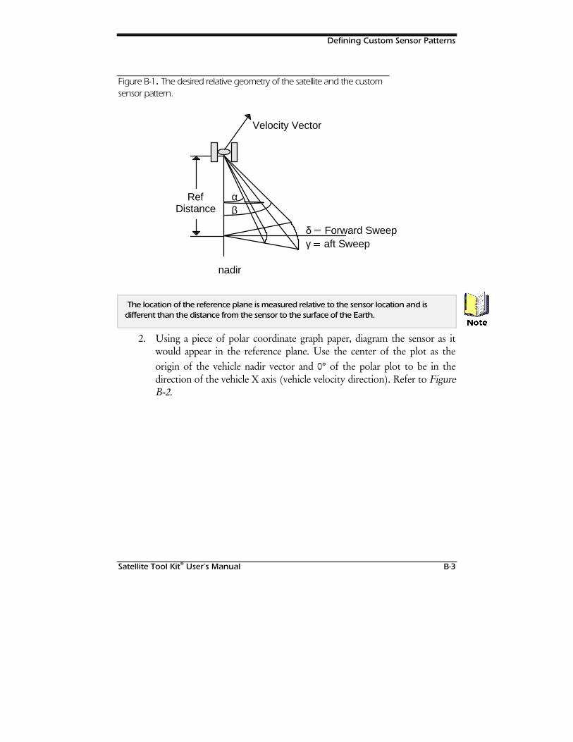
Defining Custom Sensor Patterns
Satellite Tool Kit® User’s Manual B-3
Figure B-1. The desired relative geometry of the satellite and the customsensor pattern.
αβ
δ Forward Sweepγ aft Sweep
nadir
RefDistance
Velocity Vector
The location of the reference plane is measured relative to the sensor location and isdifferent than the distance from the sensor to the surface of the Earth.
2. Using a piece of polar coordinate graph paper, diagram the sensor as itwould appear in the reference plane. Use the center of the plot as theorigin of the vehicle nadir vector and 0° of the polar plot to be in thedirection of the vehicle X axis (vehicle velocity direction). Refer to FigureB-2.
1RWH
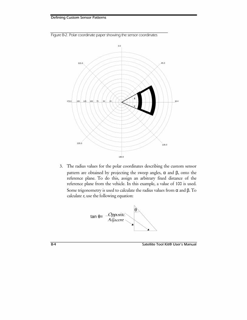
Defining Custom Sensor Patterns
B-4 Satellite Tool Kit® User’s Manual
Figure B-2. Polar coordinate paper showing the sensor coordinates
270.0 150 125 100 75 50 25 90.0δ
γ
135.0
180.0
225.0
45.0315.0
0.0
3. The radius values for the polar coordinates describing the custom sensorpattern are obtained by projecting the sweep angles, α and β, onto thereference plane. To do this, assign an arbitrary fixed distance of thereference plane from the vehicle. In this example, a value of 100 is used.Some trigonometry is used to calculate the radius values from α and β. Tocalculate r, use the following equation:
tan θ= 1RRQUKVG
#FLCEGPV
θ

Defining Custom Sensor Patterns
Satellite Tool Kit® User’s Manual B-5
where Opposite equals r or the length of the line from the vehicle nadirvector to the sensor pattern edge, in the reference plane, and Adjacentequals the reference plane distance. For this example, the referencedistance is 100 units.
Your calculations would be:
α =
=
= ×=
40
40100
40 100
8391
0
tan
tan
.
r
r
r
β =
=
= ×=
50
50100
50 100
119175
0
tan
tan
.
r
r
r
4. Once you have projected the sensor pattern onto the graph paper, read offa suitable number of points to describe the shape of the pattern. Eachpoint is specific by r, the radial distance from the center, and theta, theangle measured from straight up, clockwise. Table 1 below, shows thepolar coordinates derived from our example:
Table B-1. Polar coordinates
r theta
83.91 60.0
83.91 70.0
83.91 80.0
83.91 90.0
83.91 100.00
83.91 110.0
83.91 120.0
119.175 120.0
119.175 110.0

Defining Custom Sensor Patterns
B-6 Satellite Tool Kit® User’s Manual
r theta
119.175 100.0
119.175 90.0
119.175 80.0
119.175 70.0
119.175 60.0
5. Create the Custom Pattern file. Now that you have the polar coordinatesfor your custom sensor pattern, create a new file in your STK Database(STKdb) directory. The file name should be a descriptive name of 20characters or less.
6. Once the file has been created, open it using a standard text editor andenter the information in the format shown in the sample custom sensorpattern file below. Notice that the first point is repeated as the last point sothat the sensor pattern is closed. When you finish, close and save the file.
We recommend using a convention such as a ‘.Pattern’ extension for sensor pattern files.
Listing B-1. STK Custom Pattern File
stk.v.3.0ReferenceDistance 100.0NumberPoints 15PatternData
83.91 60.083.91 70.083.91 80.083.91 90.083.91 100.0083.91 110.083.91 120.0119.175 120.0119.175 110.0119.175 100.0119.175 90.0119.175 80.0119.175 70.0119.175 60.083.91 60.0
EndPatternData
+LQW
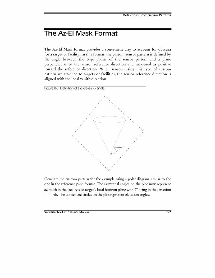
Defining Custom Sensor Patterns
Satellite Tool Kit® User’s Manual B-7
The Az-El Mask Format
The Az-El Mask format provides a convenient way to account for obscurafor a target or facility. In this format, the custom sensor pattern is defined bythe angle between the edge points of the sensor pattern and a planeperpendicular to the sensor reference direction and measured as positivetoward the reference direction. When sensors using this type of custompattern are attached to targets or facilities, the sensor reference direction isaligned with the local zenith direction.
Figure B-3. Definition of the elevation angle.
elevation
Generate the custom pattern for the example using a polar diagram similar to theone in the reference pane format. The azimuthal angles on the plot now representazimuth in the facility’s or target’s local horizon plane with 0° being in the directionof north. The concentric circles on the plot represent elevation angles.
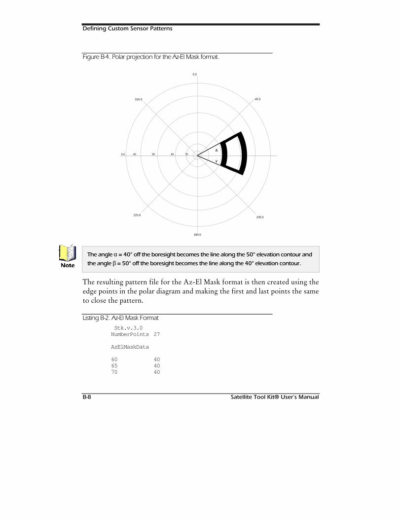
Defining Custom Sensor Patterns
B-8 Satellite Tool Kit® User’s Manual
Figure B-4. Polar projection for the Az-El Mask format.
0.0 40 50 60 70δ
γ
135.0
180.0
225.0
45.0315.0
0.0
The angle α = 40° off the boresight becomes the line along the 50° elevation contour and
the angle β = 50° off the boresight becomes the line along the 40° elevation contour.
The resulting pattern file for the Az-El Mask format is then created using theedge points in the polar diagram and making the first and last points the sameto close the pattern.
Listing B-2. Az-El Mask Format
Stk.v.3.0NumberPoints 27
AzElMaskData
60 4065 4070 40
1RWH
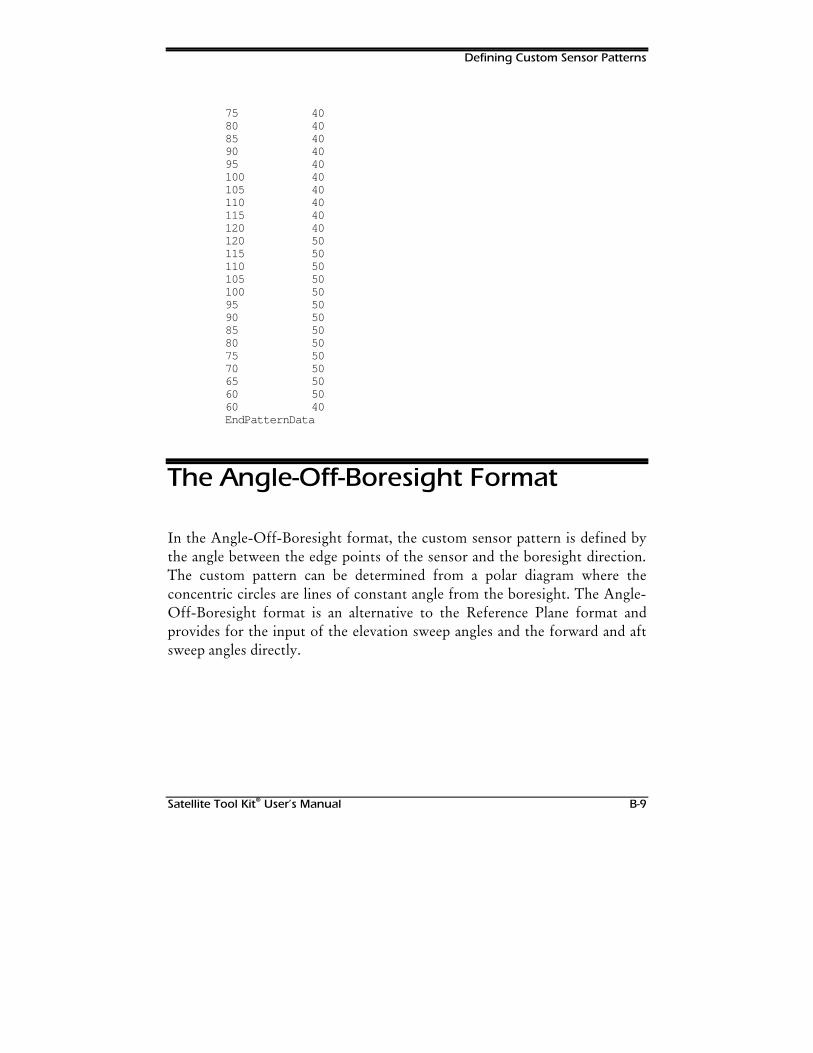
Defining Custom Sensor Patterns
Satellite Tool Kit® User’s Manual B-9
75 4080 4085 4090 4095 40100 40105 40110 40115 40120 40120 50115 50110 50105 50100 5095 5090 5085 5080 5075 5070 5065 5060 5060 40EndPatternData
The Angle-Off-Boresight Format
In the Angle-Off-Boresight format, the custom sensor pattern is defined bythe angle between the edge points of the sensor and the boresight direction.The custom pattern can be determined from a polar diagram where theconcentric circles are lines of constant angle from the boresight. The Angle-Off-Boresight format is an alternative to the Reference Plane format andprovides for the input of the elevation sweep angles and the forward and aftsweep angles directly.
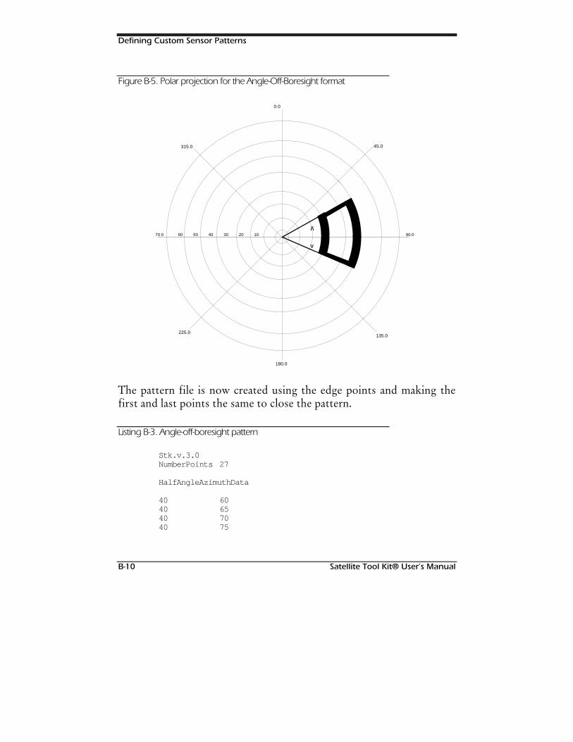
Defining Custom Sensor Patterns
B-10 Satellite Tool Kit® User’s Manual
Figure B-5. Polar projection for the Angle-Off-Boresight format
70.0 60 50 40 30 20 10 90.0δ
γ
135.0
180.0
225.0
45.0315.0
0.0
The pattern file is now created using the edge points and making thefirst and last points the same to close the pattern.
Listing B-3. Angle-off-boresight pattern
Stk.v.3.0NumberPoints 27
HalfAngleAzimuthData
40 6040 6540 7040 75

Defining Custom Sensor Patterns
Satellite Tool Kit® User’s Manual B-11
40 8040 8540 9040 9540 10040 10540 11040 11540 12050 12050 11550 11050 10550 10050 9550 9050 8550 8050 7550 7050 6550 6040 60EndPatternData

Defining Custom Sensor Patterns
B-12 Satellite Tool Kit® User’s Manual
127(6
Satellite Tool Kit® User’s Manual C-1
Appendix C
IMPORTING FILESINTO STK
Overview
STK users can create external files of data that can be imported into STK andused to provide reference data for an object. These objects must conform tothe appropriate file format.
The sample files shown in this appendix are for illustrative purposes only. ,W LV QRW WKHSXUSRVH RI WKLV DSSHQGL[ WR LQGLFDWH WKH IXOO UDQJH RI FKRLFHV RU SRVVLELOLWLHV IRU D
JLYHQ REMHFW
External files must be arranged in blocks, called Keyword Groups, that areset off with the word BEGIN and the group name (e.g., BEGIN Attitude )at the start of the block and the word END and the group name (e.g., ENDAttitude ) at the end of the block. The information contained in the blockconsists of keywords (e.g., NumberOfAttitudePoints ) and values (e.g.,3) that are called keyword phrases. Therefore, a keyword phrase would be:
NumberOfTorques 20
You can currently import data from the following types of external files:
:DUQLQJ
Importing Files into STK
C-2 Satellite Tool Kit® User’s Manual
♦ .xpm files ♦ external ephemeris files ♦ attitude files
♦ torque files ♦ az-el files ♦ STK database files
♦ planet files ♦ custom sensor files ♦ solar flux files
Chapter Contents
Overview .....................................................................................................C-1
Attitude File Format......................................................................................C-3
Az-El File (.aem) Format................................................................................C-8
Custom Sensor File Format ..........................................................................C-9
Ephemeris File Format (.e) ...........................................................................C-9
Planetary Ephemeris File (.pe) Format....................................................... C-17
Torque File (.tq) Format ............................................................................ C-18
Color Bitmap/Pixmap (.bmp/.xpm) File Format ........................................ C-19
Database File Formats............................................................................... C-20
Satellite Database................................................................................. C-20
TLE File Format..................................................................................... C-26
City Database....................................................................................... C-29
Facility Database .................................................................................. C-32
Star Database....................................................................................... C-34
Solar Flux Files ........................................................................................... C-38
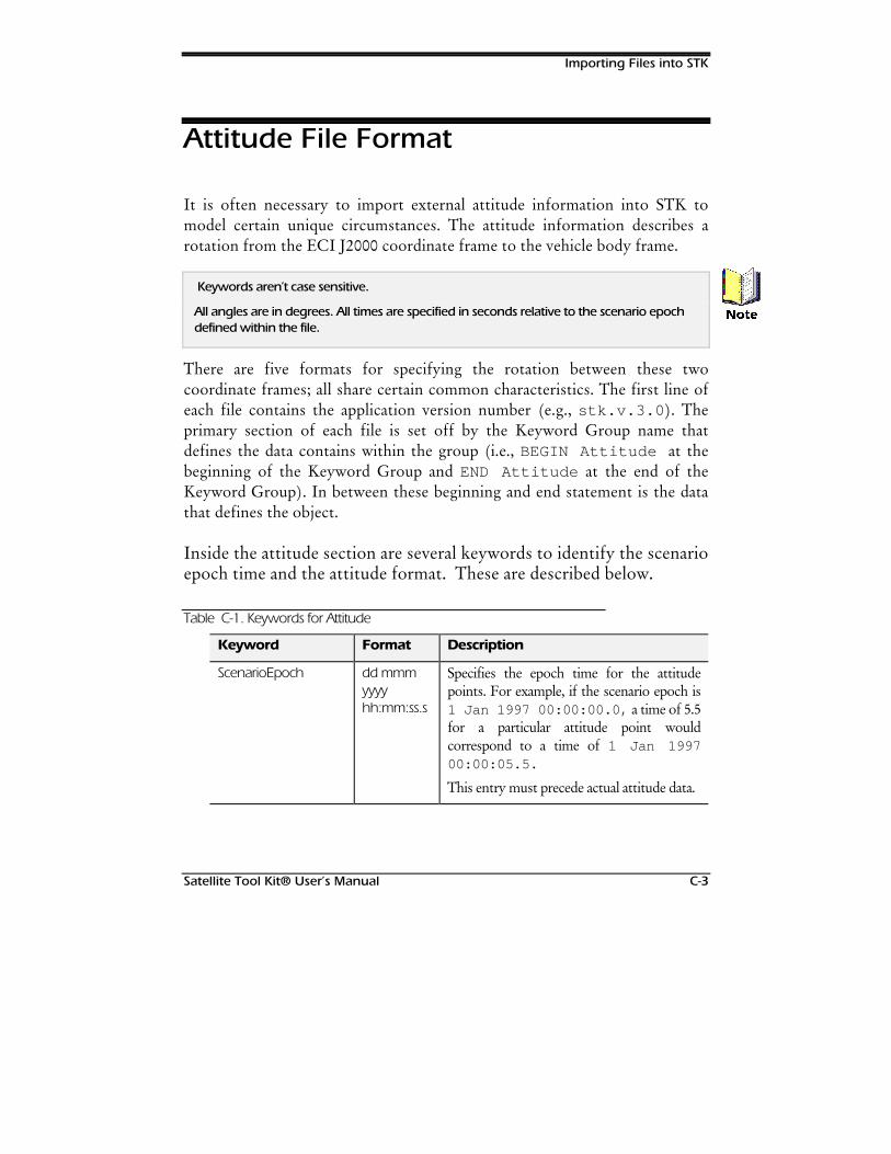
Importing Files into STK
Satellite Tool Kit® User’s Manual C-3
Attitude File Format
It is often necessary to import external attitude information into STK tomodel certain unique circumstances. The attitude information describes arotation from the ECI J2000 coordinate frame to the vehicle body frame.
Keywords aren’t case sensitive.
All angles are in degrees. All times are specified in seconds relative to the scenario epochdefined within the file.
There are five formats for specifying the rotation between these twocoordinate frames; all share certain common characteristics. The first line ofeach file contains the application version number (e.g., stk.v.3.0 ). Theprimary section of each file is set off by the Keyword Group name thatdefines the data contains within the group (i.e., BEGIN Attitude at thebeginning of the Keyword Group and END Attitude at the end of theKeyword Group). In between these beginning and end statement is the datathat defines the object.
Inside the attitude section are several keywords to identify the scenarioepoch time and the attitude format. These are described below.
Table C-1. Keywords for Attitude
Keyword Format Description
ScenarioEpoch dd mmmyyyyhh:mm:ss.s
Specifies the epoch time for the attitudepoints. For example, if the scenario epoch is1 Jan 1997 00:00:00.0, a time of 5.5for a particular attitude point wouldcorrespond to a time of 1 Jan 199700:00:05.5.
This entry must precede actual attitude data.
1RWH
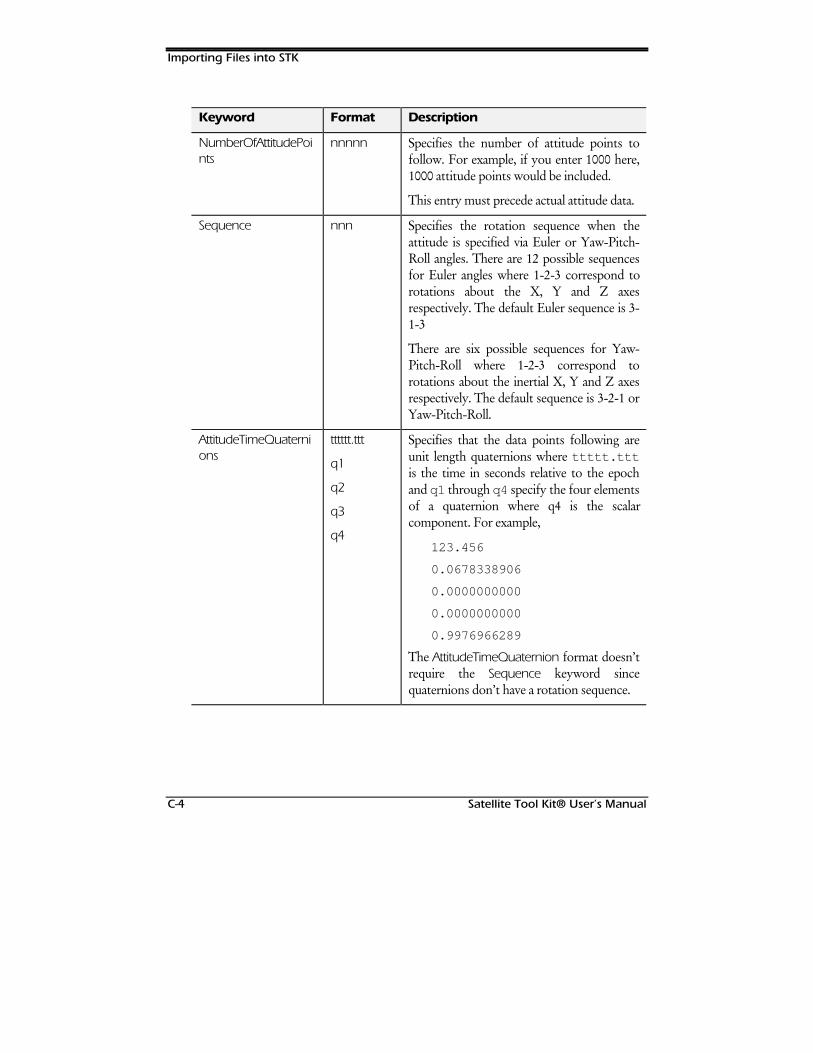
Importing Files into STK
C-4 Satellite Tool Kit® User’s Manual
Keyword Format Description
NumberOfAttitudePoints
nnnnn Specifies the number of attitude points tofollow. For example, if you enter 1000 here,1000 attitude points would be included.
This entry must precede actual attitude data.
Sequence nnn Specifies the rotation sequence when theattitude is specified via Euler or Yaw-Pitch-Roll angles. There are 12 possible sequencesfor Euler angles where 1-2-3 correspond torotations about the X, Y and Z axesrespectively. The default Euler sequence is 3-1-3
There are six possible sequences for Yaw-Pitch-Roll where 1-2-3 correspond torotations about the inertial X, Y and Z axesrespectively. The default sequence is 3-2-1 orYaw-Pitch-Roll.
AttitudeTimeQuaternions
tttttt.ttt
q1
q2
q3
q4
Specifies that the data points following areunit length quaternions where ttttt.tttis the time in seconds relative to the epochand q1 through q4 specify the four elementsof a quaternion where q4 is the scalarcomponent. For example,
123.456
0.0678338906
0.0000000000
0.0000000000
0.9976966289
The AttitudeTimeQuaternion format doesn’trequire the Sequence keyword sincequaternions don’t have a rotation sequence.
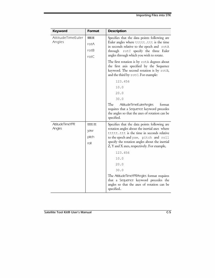
Importing Files into STK
Satellite Tool Kit® User’s Manual C-5
Keyword Format Description
AttitudeTimeEulerAngles
tttttt.ttt
rotA
rotB
rotC
Specifies that the data points following areEuler angles where ttttt.ttt is the timein seconds relative to the epoch and rotAthrough rotC specify the three Eulerangles through which you wish to rotate.
The first rotation is by rotA degrees aboutthe first axis specified by the Sequencekeyword. The second rotation is by rotB ,and the third by rotC . For example:
123.456
10.0
20.0
30.0
The AttitudeTimeEulerAngles formatrequires that a Sequence keyword precedesthe angles so that the axes of rotation can bespecified.
AttitudeTimeYPRAngles
tttttt.ttt
yaw
pitch
roll
Specifies that the data points following arerotation angles about the inertial axes wherettttt.ttt is the time in seconds relativeto the epoch and yaw, pitch and rollspecify the rotation angles about the inertialZ, Y and X axes, respectively. For example,
123.456
10.0
20.0
30.0
The AttitudeTimeYPRAngles format requiresthat a Sequence keyword precedes theangles so that the axes of rotation can bespecified..
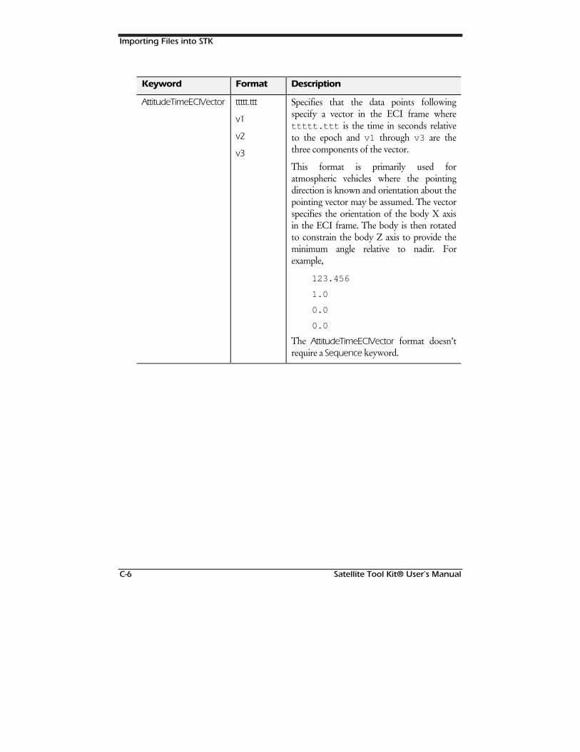
Importing Files into STK
C-6 Satellite Tool Kit® User’s Manual
Keyword Format Description
AttitudeTimeECIVector ttttt.ttt
v1
v2
v3
Specifies that the data points followingspecify a vector in the ECI frame wherettttt.ttt is the time in seconds relativeto the epoch and v1 through v3 are thethree components of the vector.
This format is primarily used foratmospheric vehicles where the pointingdirection is known and orientation about thepointing vector may be assumed. The vectorspecifies the orientation of the body X axisin the ECI frame. The body is then rotatedto constrain the body Z axis to provide theminimum angle relative to nadir. Forexample,
123.456
1.0
0.0
0.0
The AttitudeTimeECIVector format doesn’trequire a Sequence keyword.
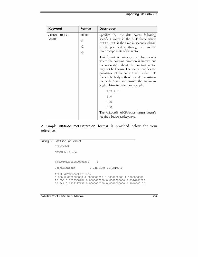
Importing Files into STK
Satellite Tool Kit® User’s Manual C-7
Keyword Format Description
AttitudeTimeECFVector
ttttt.ttt
v1
v2
v3
Specifies that the data points followingspecify a vector in the ECF frame wherettttt.ttt is the time in seconds relativeto the epoch and v1 through v3 are thethree components of the vector.
This format is primarily used for rocketswhere the pointing direction is known butthe orientation about the pointing vectormay not be known. The vector specifies theorientation of the body X axis in the ECFframe. The body is then rotated to constrainthe body Z axis and provide the minimumangle relative to nadir. For example,
123.456
1.0
0.0
0.0
The AttitudeTimeECFVector format doesn’trequire a Sequence keyword.
A sample AttitudeTimeQuaternion format is provided below for yourreference.
Listing C-1. Attitude File Format
stk.v.3.0
BEGIN Attitude
NumberOfAttitudePoints 3
ScenarioEpoch 1 Jan 1995 00:00:00.0
AttitudeTimeQuaternions0.000 0.0000000000 0.0000000000 0.0000000000 1.000000000015.558 0.0678338906 0.0000000000 0.0000000000 0.997696628930.644 0.1333127632 0.0000000000 0.0000000000 0.9910740170

Importing Files into STK
C-8 Satellite Tool Kit® User’s Manual
END Attitude
Az-El File (.aem) Format
The data in an external az-el file should start at zero azimuth and go to anazimuth of 360°. Elevation values can range from -90° to 90°. The format ofeach data line is:
azimuth elevation
A sample Az-El file is shown below.
Listing C-2. Sample Az-El File Format
stk.v.3.0
BEGIN AzElMask
NumberOfPoints 67
Begin AzElMaskData
0.0 5.05.0 5.06.0 6.07.0 7.08.0 8.09.0 9.010.0 10.011.0 9.012.0 8.013.0 7.014.0 6.015.0 5.020.0 5.025.0 5.027.5 7.5...267.5 22.5
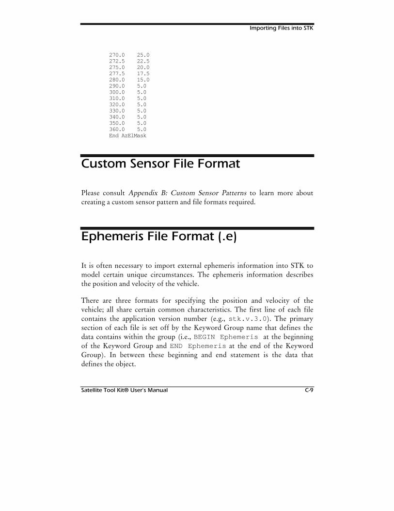
Importing Files into STK
Satellite Tool Kit® User’s Manual C-9
270.0 25.0272.5 22.5275.0 20.0277.5 17.5280.0 15.0290.0 5.0300.0 5.0310.0 5.0320.0 5.0330.0 5.0340.0 5.0350.0 5.0360.0 5.0End AzElMask
Custom Sensor File Format
Please consult Appendix B: Custom Sensor Patterns to learn more aboutcreating a custom sensor pattern and file formats required.
Ephemeris File Format (.e)
It is often necessary to import external ephemeris information into STK tomodel certain unique circumstances. The ephemeris information describesthe position and velocity of the vehicle.
There are three formats for specifying the position and velocity of thevehicle; all share certain common characteristics. The first line of each filecontains the application version number (e.g., stk.v.3.0 ). The primarysection of each file is set off by the Keyword Group name that defines thedata contains within the group (i.e., BEGIN Ephemeris at the beginningof the Keyword Group and END Ephemeris at the end of the KeywordGroup). In between these beginning and end statement is the data thatdefines the object.
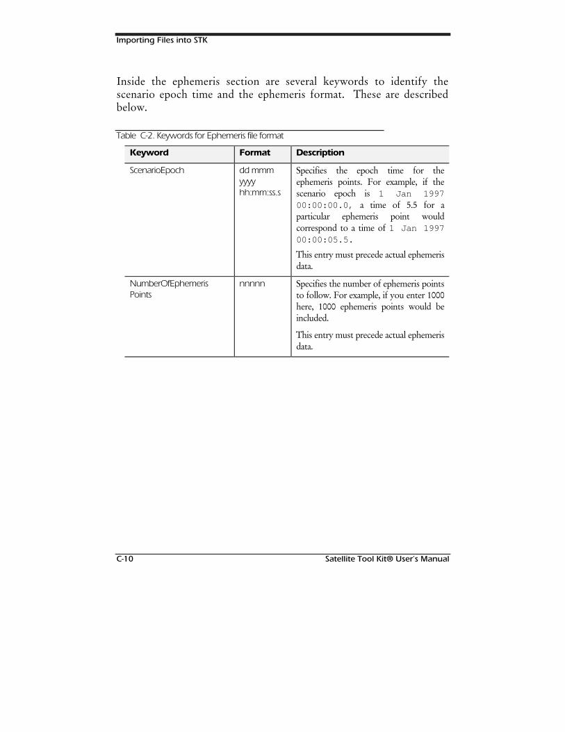
Importing Files into STK
C-10 Satellite Tool Kit® User’s Manual
Inside the ephemeris section are several keywords to identify thescenario epoch time and the ephemeris format. These are describedbelow.
Table C-2. Keywords for Ephemeris file format
Keyword Format Description
ScenarioEpoch dd mmmyyyyhh:mm:ss.s
Specifies the epoch time for theephemeris points. For example, if thescenario epoch is 1 Jan 199700:00:00.0, a time of 5.5 for aparticular ephemeris point wouldcorrespond to a time of 1 Jan 199700:00:05.5.
This entry must precede actual ephemerisdata.
NumberOfEphemerisPoints
nnnnn Specifies the number of ephemeris pointsto follow. For example, if you enter 1000here, 1000 ephemeris points would beincluded.
This entry must precede actual ephemerisdata.
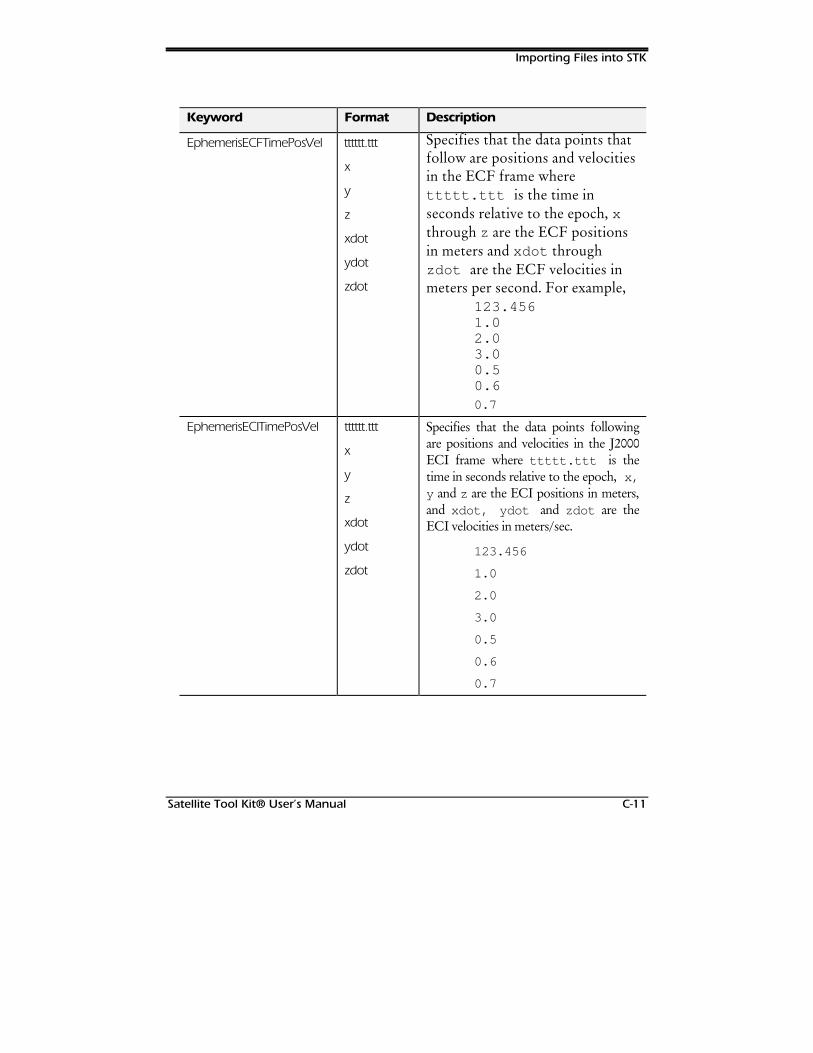
Importing Files into STK
Satellite Tool Kit® User’s Manual C-11
Keyword Format Description
EphemerisECFTimePosVel tttttt.ttt
x
y
z
xdot
ydot
zdot
Specifies that the data points thatfollow are positions and velocitiesin the ECF frame wherettttt.ttt is the time inseconds relative to the epoch, xthrough z are the ECF positionsin meters and xdot throughzdot are the ECF velocities inmeters per second. For example,
123.4561.02.03.00.50.60.7
EphemerisECITimePosVel tttttt.ttt
x
y
z
xdot
ydot
zdot
Specifies that the data points followingare positions and velocities in the J2000ECI frame where ttttt.ttt is thetime in seconds relative to the epoch, x,y and z are the ECI positions in meters,and xdot, ydot and zdot are theECI velocities in meters/sec.
123.456
1.0
2.0
3.0
0.5
0.6
0.7

Importing Files into STK
C-12 Satellite Tool Kit® User’s Manual
Keyword Format Description
EphemerisLLRTimePosVel tttttt.ttt
lat
lon
rad
latdot
londot
raddot
Specifies that the data points followingare positions and velocities in an ECFframe where ttttt.ttt is the time inseconds relative to the epoch, lat,lon and rad are the geocentric latitude,longitude and radius (in degrees andmeters, respectively), and latdot,londot , and raddot are the rates ofchange of these parameters per second.
123.456
1.0
2.0
3.0
0.5
0.6
0.7
EphemerisLLATimePosVel tttttt.ttt
lat
lon
alt
latdot
londot
altdot
Specifies that the data points followingare positions and velocities in an ECFframe where ttttt.ttt is the time inseconds relative to the epoch, lat,lon and rad are the geocentric latitude,longitude and altitude (in degrees andmeters, respectively), and latdot,londot , and altdot are the rates ofchange of these parameters per second.
123.456
1.0
2.0
3.0
0.5
0.6
0.7
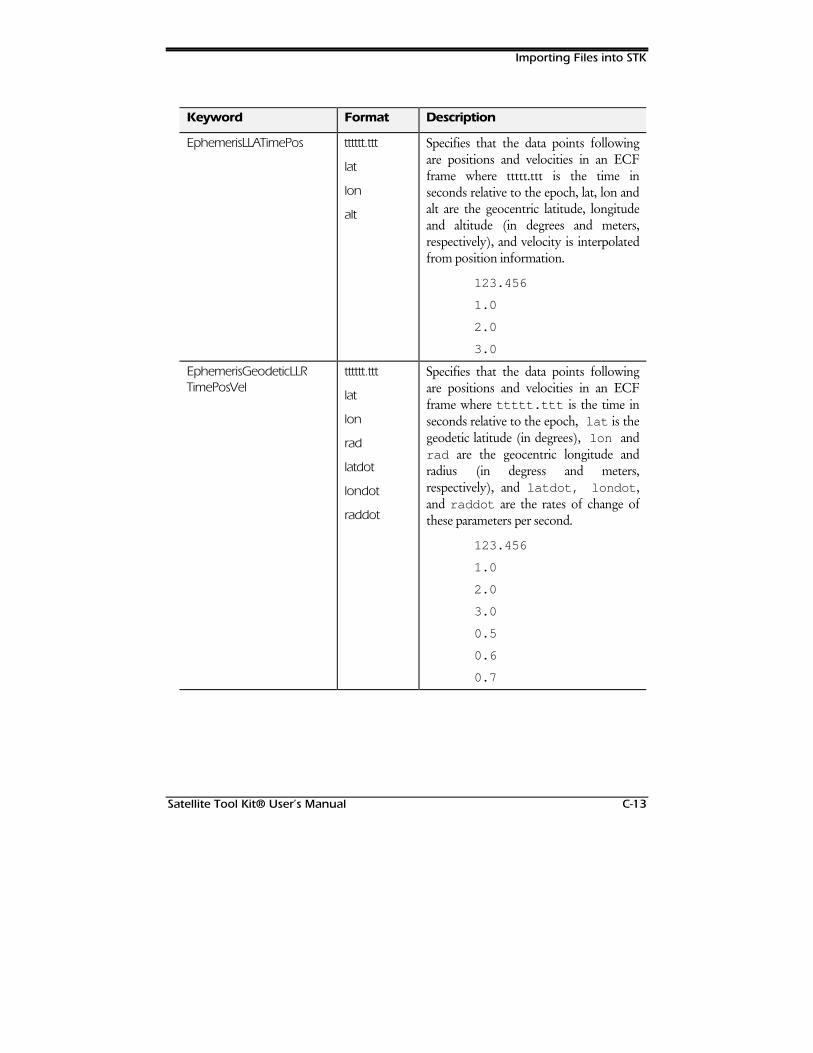
Importing Files into STK
Satellite Tool Kit® User’s Manual C-13
Keyword Format Description
EphemerisLLATimePos tttttt.ttt
lat
lon
alt
Specifies that the data points followingare positions and velocities in an ECFframe where ttttt.ttt is the time inseconds relative to the epoch, lat, lon andalt are the geocentric latitude, longitudeand altitude (in degrees and meters,respectively), and velocity is interpolatedfrom position information.
123.456
1.0
2.0
3.0
EphemerisGeodeticLLRTimePosVel
tttttt.ttt
lat
lon
rad
latdot
londot
raddot
Specifies that the data points followingare positions and velocities in an ECFframe where ttttt.ttt is the time inseconds relative to the epoch, lat is thegeodetic latitude (in degrees), lon andrad are the geocentric longitude andradius (in degress and meters,respectively), and latdot, londot ,and raddot are the rates of change ofthese parameters per second.
123.456
1.0
2.0
3.0
0.5
0.6
0.7
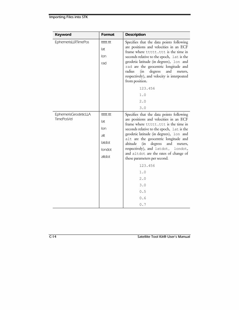
Importing Files into STK
C-14 Satellite Tool Kit® User’s Manual
Keyword Format Description
EphemerisLLRTimePos tttttt.ttt
lat
lon
rad
Specifies that the data points followingare positions and velocities in an ECFframe where ttttt.ttt is the time inseconds relative to the epoch, lat is thegeodetic latitude (in degrees), lon andrad are the geocentric longitude andradius (in degress and meters,respectively), and velocity is interpoatedfrom position.
123.456
1.0
2.0
3.0
EphemerisGeodeticLLATimePosVel
tttttt.ttt
lat
lon
alt
latdot
londot
altdot
Specifies that the data points followingare positions and velocities in an ECFframe where ttttt.ttt is the time inseconds relative to the epoch, lat is thegeodetic latitude (in degrees), lon andalt are the geocentric longitude andaltitude (in degress and meters,respectively), and latdot, londot ,and altdot are the rates of change ofthese parameters per second.
123.456
1.0
2.0
3.0
0.5
0.6
0.7
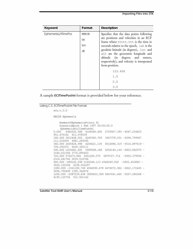
Importing Files into STK
Satellite Tool Kit® User’s Manual C-15
Keyword Format Description
EphemerisLLATimePos tttttt.ttt
lat
lon
alt
Specifies that the data points followingare positions and velocities in an ECFframe where ttttt.ttt is the time inseconds relative to the epoch, lat is thegeodetic latitude (in degrees), lon andalt are the geocentric longitude andaltitude (in degress and meters,respectively), and velocity is interpoatedfrom position.
123.456
1.0
2.0
3.0
A sample ECITimePosVel format is provided below for your reference.
Listing C-3. ECITimePosVel File Format
stk.v.3.0
BEGIN Ephemeris
NumberOfEphemerisPoints 81 ScenarioEpoch 1 Feb 1997 00:00:00.0
EphemerisEciTimePosVel0.000 4482020.588 6164585.645 2729927.393 -4547.234623951.470332 413.978539180.000 3612448.002 6260360.709 3667378.031 -5094.799967111.016509 4981.283095360.000 2655428.996 6204621.135 4516086.319 -5516.897019 -728.292472 4430.320111540.000 1634481.691 5999568.188 5256140.144 -5803.862975 -1544.431356 3776.895453720.000 574473.966 5651265.575 5870727.714 -5950.379934 -2316.641762 3039.516766900.000 -499160.298 5169344.113 6346549.050 -5955.453865 -3026.155186 2238.5522971080.000 -1561180.749 4566590.678 6674072.962 -5822.172445 -3656.750499 1395.3669761260.000 -2587239.838 3858453.389 6847641.465 -5557.286368 -4195.125756 531.501142

Importing Files into STK
C-16 Satellite Tool Kit® User’s Manual
1440.000 -3554494.945 3062496.633 6865434.196 -5170.669349 -4631.085339 -32.0565901620.000 -4442116.708 2197837.759 6729313.077 -4674.714035 -4957.560849 -1175.4687441800.000 -5231686.802 1284592.763 6444571.853 -4083.715763 -5170.495904 -1980.5054021980.000 -5907486.937 343352.289 6019616.386 -3413.286064 -5268.630747 -2730.8585002160.000 -6456687.278 -605297.336 5465600.255 -2679.825521 -5253.223006 -3412.3270402340.000 -6869446.698 -1541199.542 4796037.111 -1900.073243 -5127.737423 -4012.8940602520.000 -7138939.400 -2444996.408 4026407.100 -1090.739409 -4897.531535 -4522.7198232700.000 -7261322.752 -3298442.157 3173770.169 -268.218800 -4569.557398 -4934.0760682880.000 -7235660.286 -4084665.462 2256394.786 551.622744 -4152.092738 -5241.2441743060.000 -7063811.956 -4788386.596 1293406.737 1353.600749 -3654.508837 -5440.3968003240.000 -6750301.443 -5396096.317 304459.508 2123.316980 -3087.077539 -5529.4786463420.000 -6302167.805 -5896203.448 -690574.686 2847.230851 -2460.815868 -5508.0980323600.000 -5728806.270 -6279157.561 -1671895.966 3512.710923 -1787.363905 -5377.4372813780.000 -5041800.589 -6537552.206 -2620053.781 4108.079054 -1078.889481 -5140.1865513960.000 -4254747.258 -6666212.808 -3516214.250 4622.658410 -348.011787 -4800.5028324140.000 -3383070.009 -6662271.858 -4342422.338 5046.835053392.265087 -4363.993155...12780.000 2198116.617 -4297359.089 -6975286.537 5428.7518744079.415361 -540.42456612960.000 3148502.990 -3520073.536 -6998208.867 5111.5917444542.840873 288.13597213140.000 4031389.170 -2667417.179 -6871206.220 4679.5116934914.960125 122.51474613320.000 4826582.047 -1756815.646 -6594825.550 4138.4400915185.004699 1944.83240913500.000 5515207.181 -807491.784 -6172911.580 3497.1263455343.847500 2736.38531213680.000 6080228.073 159870.353 -5612720.047 2767.2534865384.457342 3478.05448513860.000 6506976.556 1123544.523 -4924947.255 1963.4434385302.361661 4150.82612214040.000 6783672.006 2061262.792 -4123656.465 1103.1224985096.082509 4736.414937
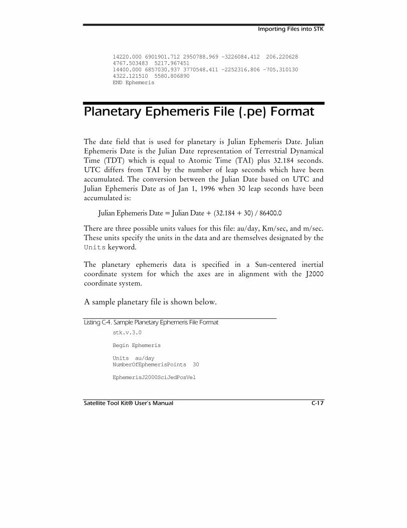
Importing Files into STK
Satellite Tool Kit® User’s Manual C-17
14220.000 6901901.712 2950788.969 -3226084.412 206.2206284767.503483 5217.96745114400.000 6857030.937 3770548.411 -2252316.806 -705.3101304322.121510 5580.806890END Ephemeris
Planetary Ephemeris File (.pe) Format
The date field that is used for planetary is Julian Ephemeris Date. JulianEphemeris Date is the Julian Date representation of Terrestrial DynamicalTime (TDT) which is equal to Atomic Time (TAI) plus 32.184 seconds.UTC differs from TAI by the number of leap seconds which have beenaccumulated. The conversion between the Julian Date based on UTC andJulian Ephemeris Date as of Jan 1, 1996 when 30 leap seconds have beenaccumulated is:
Julian Ephemeris Date = Julian Date + (32.184 + 30) / 86400.0
There are three possible units values for this file: au/day, Km/sec, and m/sec.These units specify the units in the data and are themselves designated by theUnits keyword.
The planetary ephemeris data is specified in a Sun-centered inertialcoordinate system for which the axes are in alignment with the J2000coordinate system.
A sample planetary file is shown below.
Listing C-4. Sample Planetary Ephemeris File Format
stk.v.3.0
Begin Ephemeris
Units au/dayNumberOfEphemerisPoints 30
EphemerisJ2000SciJedPosVel
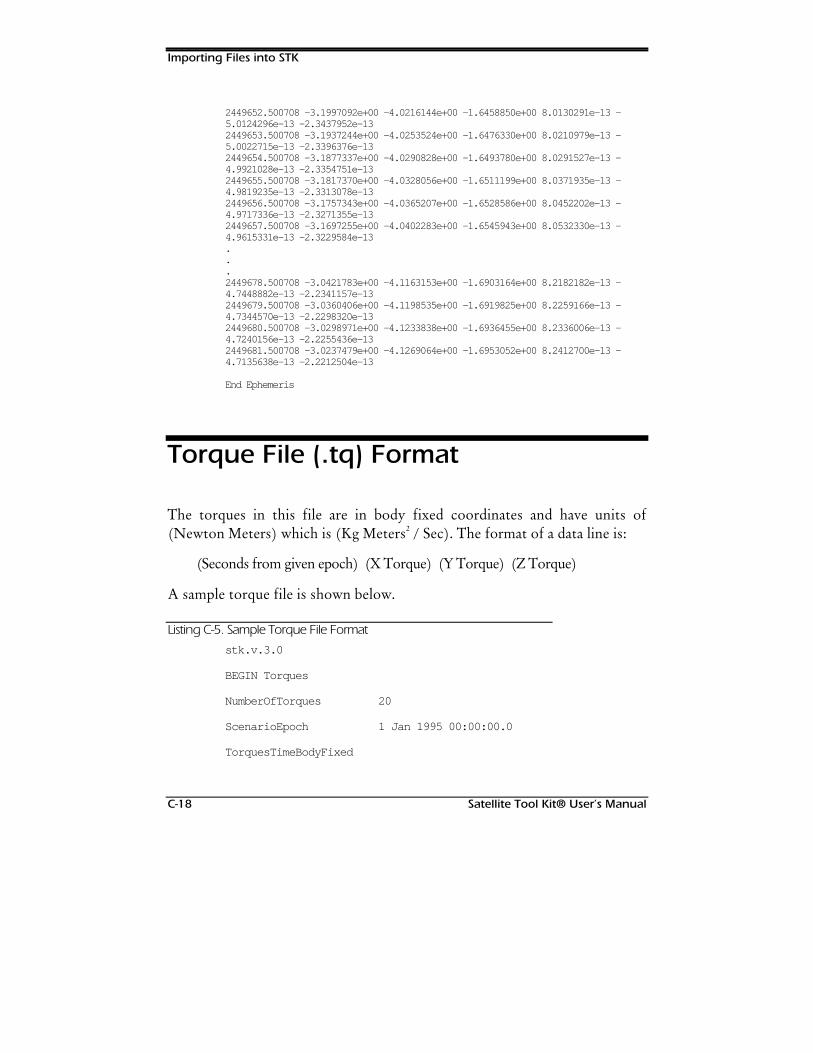
Importing Files into STK
C-18 Satellite Tool Kit® User’s Manual
2449652.500708 -3.1997092e+00 -4.0216144e+00 -1.6458850e+00 8.0130291e-13 -5.0124296e-13 -2.3437952e-132449653.500708 -3.1937244e+00 -4.0253524e+00 -1.6476330e+00 8.0210979e-13 -5.0022715e-13 -2.3396376e-132449654.500708 -3.1877337e+00 -4.0290828e+00 -1.6493780e+00 8.0291527e-13 -4.9921028e-13 -2.3354751e-132449655.500708 -3.1817370e+00 -4.0328056e+00 -1.6511199e+00 8.0371935e-13 -4.9819235e-13 -2.3313078e-132449656.500708 -3.1757343e+00 -4.0365207e+00 -1.6528586e+00 8.0452202e-13 -4.9717336e-13 -2.3271355e-132449657.500708 -3.1697255e+00 -4.0402283e+00 -1.6545943e+00 8.0532330e-13 -4.9615331e-13 -2.3229584e-13...2449678.500708 -3.0421783e+00 -4.1163153e+00 -1.6903164e+00 8.2182182e-13 -4.7448882e-13 -2.2341157e-132449679.500708 -3.0360406e+00 -4.1198535e+00 -1.6919825e+00 8.2259166e-13 -4.7344570e-13 -2.2298320e-132449680.500708 -3.0298971e+00 -4.1233838e+00 -1.6936455e+00 8.2336006e-13 -4.7240156e-13 -2.2255436e-132449681.500708 -3.0237479e+00 -4.1269064e+00 -1.6953052e+00 8.2412700e-13 -4.7135638e-13 -2.2212504e-13
End Ephemeris
Torque File (.tq) Format
The torques in this file are in body fixed coordinates and have units of(Newton Meters) which is (Kg Meters2 / Sec). The format of a data line is:
(Seconds from given epoch) (X Torque) (Y Torque) (Z Torque)
A sample torque file is shown below.
Listing C-5. Sample Torque File Format
stk.v.3.0
BEGIN Torques
NumberOfTorques 20
ScenarioEpoch 1 Jan 1995 00:00:00.0
TorquesTimeBodyFixed
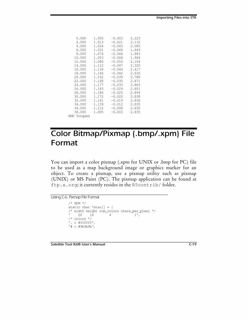
Importing Files into STK
Satellite Tool Kit® User’s Manual C-19
0.000 1.005 -0.003 2.223 2.000 1.013 -0.021 2.132 4.000 1.024 -0.043 2.085 6.000 1.031 -0.065 1.869 8.000 1.074 -0.064 1.883 10.000 1.053 -0.066 1.964 12.000 1.086 -0.053 2.104 14.000 1.112 -0.047 2.325 16.000 1.134 -0.044 2.417 18.000 1.146 -0.042 2.632 20.000 1.152 -0.039 2.788 22.000 1.168 -0.035 2.871 24.000 1.177 -0.033 2.863 26.000 1.183 -0.029 2.851 28.000 1.186 -0.025 2.844 30.000 1.172 -0.022 2.838 32.000 1.161 -0.019 2.836 34.000 1.139 -0.012 2.835 36.000 1.112 -0.008 2.835 38.000 1.005 -0.003 2.835END Torques
Color Bitmap/Pixmap (.bmp/.xpm) FileFormat
You can import a color pixmap (.xpm for UNIX or .bmp for PC) fileto be used as a map background image or graphics marker for anobject. To create a pixmap, use a pixmap utility such as pixmap(UNIX) or MS Paint (PC). The pixmap application can be found atftp.x.org ; it currently resides in the R5contrib/ folder.
Listing C-6. Pixmap File Format
/* XPM */static char *star[] = /* width height num_colors chars_per_pixel */" 20 16 4 1",/* colors */". c #ffffff","# c #9b9b9b",
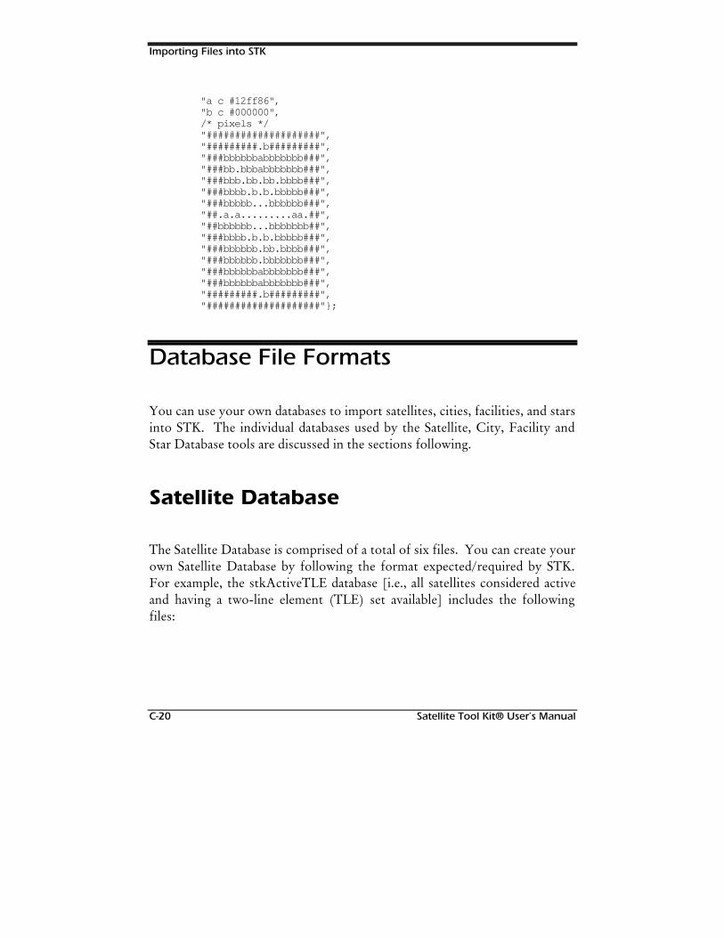
Importing Files into STK
C-20 Satellite Tool Kit® User’s Manual
"a c #12ff86","b c #000000",/* pixels */"####################","#########.b#########","###bbbbbbabbbbbbb###","###bb.bbbabbbbbbb###","###bbb.bb.bb.bbbb###","###bbbb.b.b.bbbbb###","###bbbbb...bbbbbb###","##.a.a.........aa.##","##bbbbbb...bbbbbbb##","###bbbb.b.b.bbbbb###","###bbbbbb.bb.bbbb###","###bbbbbb.bbbbbbb###","###bbbbbbabbbbbbb###","###bbbbbbabbbbbbb###","#########.b#########","####################";
Database File Formats
You can use your own databases to import satellites, cities, facilities, and starsinto STK. The individual databases used by the Satellite, City, Facility andStar Database tools are discussed in the sections following.
Satellite Database
The Satellite Database is comprised of a total of six files. You can create yourown Satellite Database by following the format expected/required by STK.For example, the stkActiveTLE database [i.e., all satellites considered activeand having a two-line element (TLE) set available] includes the followingfiles:
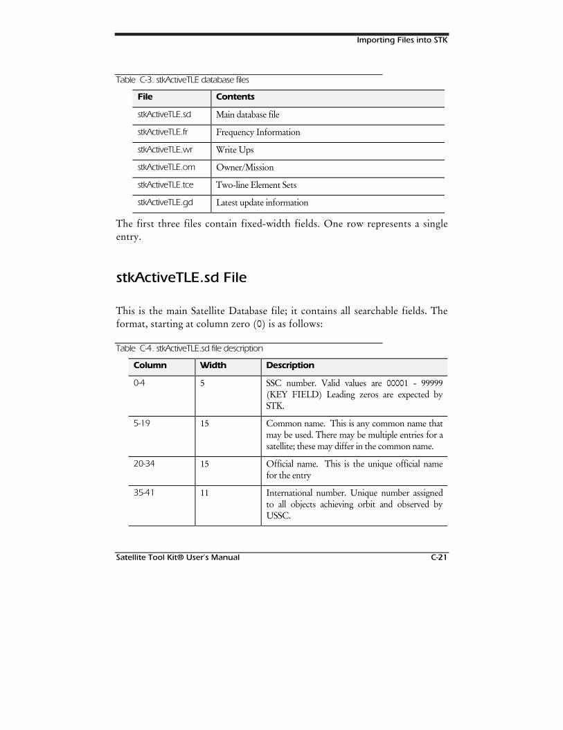
Importing Files into STK
Satellite Tool Kit® User’s Manual C-21
Table C-3. stkActiveTLE database files
File Contents
stkActiveTLE.sd Main database file
stkActiveTLE.fr Frequency Information
stkActiveTLE.wr Write Ups
stkActiveTLE.om Owner/Mission
stkActiveTLE.tce Two-line Element Sets
stkActiveTLE.gd Latest update information
The first three files contain fixed-width fields. One row represents a singleentry.
stkActiveTLE.sd File
This is the main Satellite Database file; it contains all searchable fields. Theformat, starting at column zero (0) is as follows:
Table C-4. stkActiveTLE.sd file description
Column Width Description
0-4 5 SSC number. Valid values are 00001 - 99999(KEY FIELD) Leading zeros are expected bySTK.
5-19 15 Common name. This is any common name thatmay be used. There may be multiple entries for asatellite; these may differ in the common name.
20-34 15 Official name. This is the unique official namefor the entry
35-41 11 International number. Unique number assignedto all objects achieving orbit and observed byUSSC.
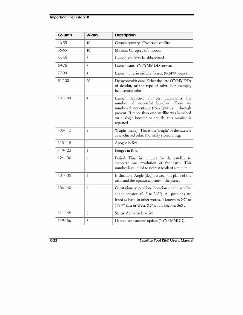
Importing Files into STK
C-22 Satellite Tool Kit® User’s Manual
Column Width Description
46-55 10 Owner/country. Owner of satellite.
56-65 10 Mission. Category of mission.
66-68 3 Launch site. May be abbreviated.
69-76 8 Launch date. YYYYMMDD format.
77-80 4 Launch time, in military format (0-2400 hours).
81-100 20 Decay/deorbit date. Either the date (YYMMDD)of deorbit, or the type of orbit. For example,heliocentric orbit
101-104 4 Launch sequence number. Represents thenumber of successful launches. These arenumbered sequentially from Sputnik 1 throughpresent. If more than one satellite was launchedon a single booster or shuttle, this number isrepeated.
105-112 8 Weight (mass). This is the 'weight' of the satelliteas it achieved orbit. Normally stored in Kg.
113-118 6 Apogee in Km.
119-123 5 Perigee in Km.
124-130 7 Period. Time in minutes for the satellite tocomplete one revolution of the earth. Thisnumber is rounded to nearest tenth of a minute.
131-135 5 Inclination. Angle (deg) between the plane of theorbit and the equatorial plane of the planet.
136-140 5 Geostationary position. Location of the satelliteat the equator. (0.1° to 360°). All positions arelisted as East. In other words, if known as 0.0° to179.9° East or West, 0.0° would become 360°.
141-148 8 Status. Active or Inactive
149-156 8 Date of last database update (YYYYMMDD)
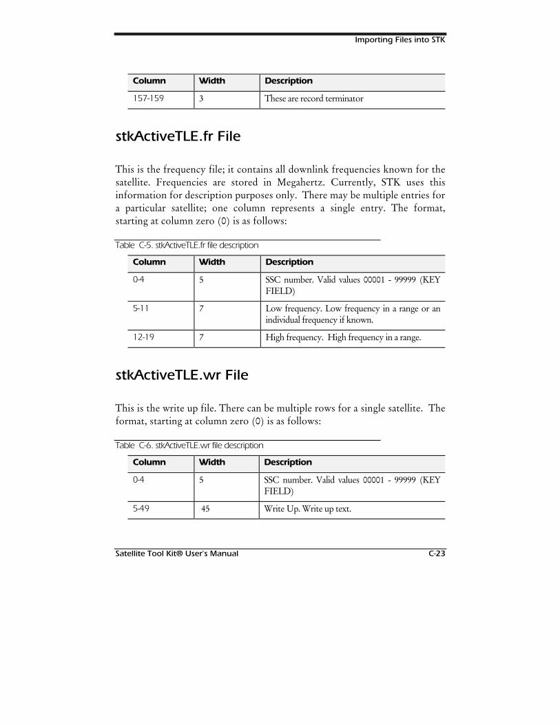
Importing Files into STK
Satellite Tool Kit® User’s Manual C-23
Column Width Description
157-159 3 These are record terminator
stkActiveTLE.fr File
This is the frequency file; it contains all downlink frequencies known for thesatellite. Frequencies are stored in Megahertz. Currently, STK uses thisinformation for description purposes only. There may be multiple entries fora particular satellite; one column represents a single entry. The format,starting at column zero (0) is as follows:
Table C-5. stkActiveTLE.fr file description
Column Width Description
0-4 5 SSC number. Valid values 00001 - 99999 (KEYFIELD)
5-11 7 Low frequency. Low frequency in a range or anindividual frequency if known.
12-19 7 High frequency. High frequency in a range.
stkActiveTLE.wr File
This is the write up file. There can be multiple rows for a single satellite. Theformat, starting at column zero (0) is as follows:
Table C-6. stkActiveTLE.wr file description
Column Width Description
0-4 5 SSC number. Valid values 00001 - 99999 (KEYFIELD)
5-49 45 Write Up. Write up text.

Importing Files into STK
C-24 Satellite Tool Kit® User’s Manual
stkActiveTLE.om File
This is the Owner/Mission file. It contains a list of all the valid owners andmissions in the database. This file is used to build the list of owners/missionavailable in the user interface. If this file isn’t available, STK is unable tosearch for satellite owners or mission. The file is in a basic STK data Fileformat.
Listing C-7. Example of owner/mission file for the satellite database
BEGIN Owner Arabia Argentina AsiaSat Australia Brazil CIS Canada China ESA FG France Germany IMSO ITSO India Indonesia Israel Italy Japan Korea LU Luxembourg Malaysia Mexico NATO Norway Spain Sweden Thailand Turkey UK USA USSR
END Owner
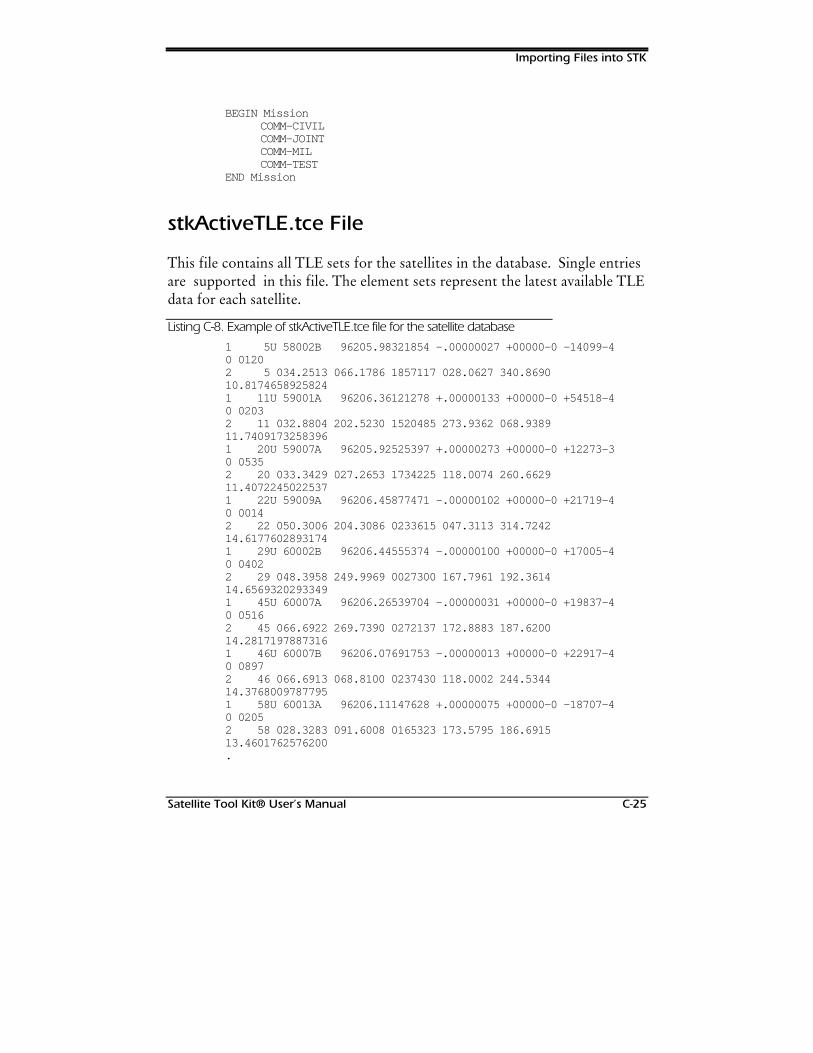
Importing Files into STK
Satellite Tool Kit® User’s Manual C-25
BEGIN Mission COMM-CIVIL COMM-JOINT COMM-MIL COMM-TEST
END Mission
stkActiveTLE.tce File
This file contains all TLE sets for the satellites in the database. Single entriesare supported in this file. The element sets represent the latest available TLEdata for each satellite.
Listing C-8. Example of stkActiveTLE.tce file for the satellite database
1 5U 58002B 96205.98321854 -.00000027 +00000-0 -14099-40 01202 5 034.2513 066.1786 1857117 028.0627 340.869010.81746589258241 11U 59001A 96206.36121278 +.00000133 +00000-0 +54518-40 02032 11 032.8804 202.5230 1520485 273.9362 068.938911.74091732583961 20U 59007A 96205.92525397 +.00000273 +00000-0 +12273-30 05352 20 033.3429 027.2653 1734225 118.0074 260.662911.40722450225371 22U 59009A 96206.45877471 -.00000102 +00000-0 +21719-40 00142 22 050.3006 204.3086 0233615 047.3113 314.724214.61776028931741 29U 60002B 96206.44555374 -.00000100 +00000-0 +17005-40 04022 29 048.3958 249.9969 0027300 167.7961 192.361414.65693202933491 45U 60007A 96206.26539704 -.00000031 +00000-0 +19837-40 05162 45 066.6922 269.7390 0272137 172.8883 187.620014.28171978873161 46U 60007B 96206.07691753 -.00000013 +00000-0 +22917-40 08972 46 066.6913 068.8100 0237430 118.0002 244.534414.37680097877951 58U 60013A 96206.11147628 +.00000075 +00000-0 -18707-40 02052 58 028.3283 091.6008 0165323 173.5795 186.691513.4601762576200.
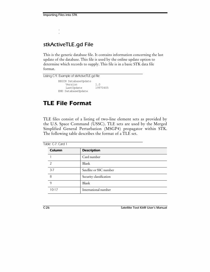
Importing Files into STK
C-26 Satellite Tool Kit® User’s Manual
.
.
stkActiveTLE.gd File
This is the generic database file. It contains information concerning the lastupdate of the database. This file is used by the online update option todetermine which records to supply. This file is in a basic STK data fileformat.
Listing C-9. Example of stkActiveTLE.gd file
BEGIN DatabaseUpdateVersion 1.0LastUpdate 19970405
END DatabaseUpdate
TLE File Format
TLE files consist of a listing of two-line element sets as provided bythe U.S. Space Command (USSC). TLE sets are used by the MergedSimplified General Perturbation (MSGP4) propagator within STK.The following table describes the format of a TLE set.
Table C-7. Card 1
Column Description
1 Card number
2 Blank
3-7 Satellite or SSC number
8 Security classification
9 Blank
10-17 International number
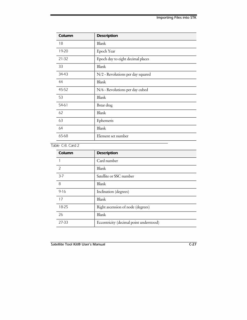
Importing Files into STK
Satellite Tool Kit® User’s Manual C-27
Column Description
18 Blank
19-20 Epoch Year
21-32 Epoch day to eight decimal places
33 Blank
34-43 N/2 - Revolutions per day squared
44 Blank
45-52 N/6 - Revolutions per day cubed
53 Blank
54-61 Bstar drag
62 Blank
63 Ephemeris
64 Blank
65-68 Element set number
Table C-8. Card 2
Column Description
1 Card number
2 Blank
3-7 Satellite or SSC number
8 Blank
9-16 Inclination (degrees)
17 Blank
18-25 Right ascension of node (degrees)
26 Blank
27-33 Eccentricity (decimal point understood)
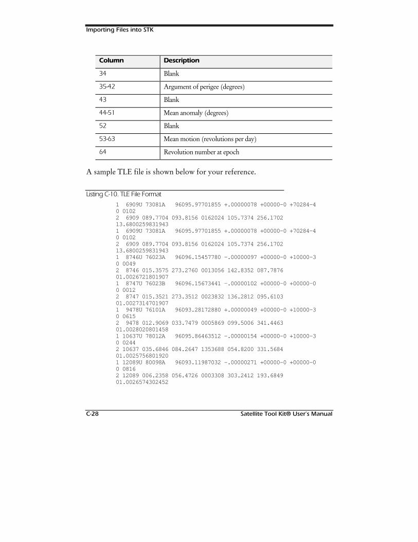
Importing Files into STK
C-28 Satellite Tool Kit® User’s Manual
Column Description
34 Blank
35-42 Argument of perigee (degrees)
43 Blank
44-51 Mean anomaly (degrees)
52 Blank
53-63 Mean motion (revolutions per day)
64 Revolution number at epoch
A sample TLE file is shown below for your reference.
Listing C-10. TLE File Format
1 6909U 73081A 96095.97701855 +.00000078 +00000-0 +70284-40 01022 6909 089.7704 093.8156 0162024 105.7374 256.170213.68002598319431 6909U 73081A 96095.97701855 +.00000078 +00000-0 +70284-40 01022 6909 089.7704 093.8156 0162024 105.7374 256.170213.68002598319431 8746U 76023A 96096.15457780 -.00000097 +00000-0 +10000-30 00492 8746 015.3575 273.2760 0013056 142.8352 087.787601.00267218019071 8747U 76023B 96096.15673441 -.00000102 +00000-0 +00000-00 00122 8747 015.3521 273.3512 0023832 136.2812 095.610301.00273147019071 9478U 76101A 96093.28172880 +.00000049 +00000-0 +10000-30 06152 9478 012.9069 033.7479 0005869 099.5006 341.446301.00280208014581 10637U 78012A 96095.86463512 -.00000154 +00000-0 +10000-30 02442 10637 035.6846 084.2647 1353688 054.8200 331.568401.00257568019201 12089U 80098A 96093.11987032 -.00000271 +00000-0 +00000-00 08162 12089 006.2358 056.4726 0003308 303.2412 193.684901.0026574302452
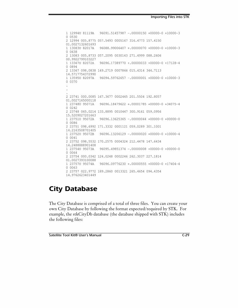
Importing Files into STK
Satellite Tool Kit® User’s Manual C-29
1 12994U 81119A 96091.51457987 -.00000150 +00000-0 +10000-30 05302 12994 005.8775 057.5493 0005167 316.4773 157.415001.00271326016931 13083U 82017A 96088.99006407 +.00000070 +00000-0 +10000-30 06382 13083 005.8733 057.2095 0030143 271.4999 088.260600.99227991032271 13367U 82072A 96096.17389770 +.00000033 +00000-0 +17128-40 08942 13367 098.0838 149.2719 0007846 015.4314 344.711314.57177543729901 13595U 82097A 96094.59762657 -.00000001 +00000-0 +10000-30 0370...2 23741 000.0085 167.3677 0002445 201.5504 192.805701.00271650001181 23748U 95071A 96096.18479622 +.00001785 +00000-0 +34075-40 02422 23748 065.0214 133.8895 0010447 300.9161 059.095615.52090272016631 23751U 95072A 96096.13625365 -.00000044 +00000-0 +00000-00 00862 23751 098.6992 171.3332 0001121 059.0289 301.100114.21635087014051 23752U 95072B 96096.13206129 -.00000020 +00000-0 +10000-40 00412 23752 098.5532 170.2575 0004324 212.4478 147.643414.24888889014081 23754U 95073A 96095.49851374 -.00000008 +00000-0 +00000-00 00642 23754 000.0342 124.0248 0002246 262.3037 227.181401.00273931000881 23757U 95074A 96096.09776230 +.00000555 +00000-0 +17404-40 00632 23757 022.9772 189.2860 0013321 265.4654 094.435414.9762623401449
City Database
The City Database is comprised of a total of three files. You can create yourown City Database by following the format expected/required by STK. Forexample, the stkCityDb database (the database shipped with STK) includesthe following files:
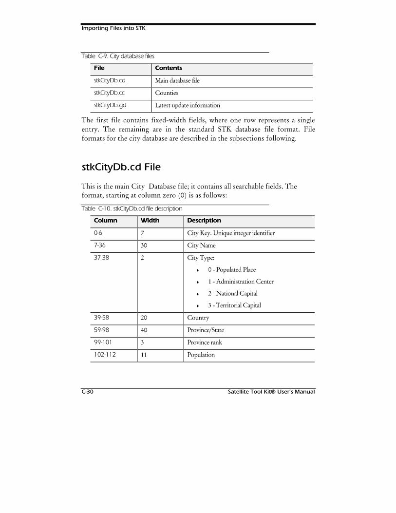
Importing Files into STK
C-30 Satellite Tool Kit® User’s Manual
Table C-9. City database files
File Contents
stkCityDb.cd Main database file
stkCityDb.cc Counties
stkCityDb.gd Latest update information
The first file contains fixed-width fields, where one row represents a singleentry. The remaining are in the standard STK database file format. Fileformats for the city database are described in the subsections following.
stkCityDb.cd File
This is the main City Database file; it contains all searchable fields. Theformat, starting at column zero (0) is as follows:
Table C-10. stkCityDb.cd file description
Column Width Description
0-6 7 City Key. Unique integer identifier
7-36 30 City Name
37-38 2 City Type:
♦ 0 - Populated Place
♦ 1 - Administration Center
♦ 2 - National Capital
♦ 3 - Territorial Capital
39-58 20 Country
59-98 40 Province/State
99-101 3 Province rank
102-112 11 Population
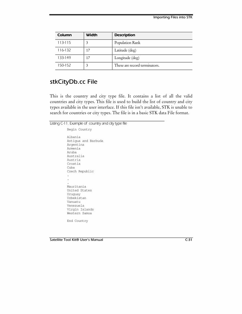
Importing Files into STK
Satellite Tool Kit® User’s Manual C-31
Column Width Description
113-115 3 Population Rank
116-132 17 Latitude (deg)
133-149 17 Longitude (deg)
150-152 3 These are record terminators.
stkCityDb.cc File
This is the country and city type file. It contains a list of all the validcountries and city types. This file is used to build the list of country and citytypes available in the user interface. If this file isn’t available, STK is unable tosearch for countries or city types. The file is in a basic STK data File format.
Listing C-11. Example of country and city type file
Begin Country
AlbaniaAntigua and BarbudaArgentinaArmeniaArubaAustraliaAustriaCroatiaCubaCzech Republic...MauritaniaUnited StatesUruguayUzbekistanVanuatuVenezuelaVirgin IslandsWestern Samoa
End Country
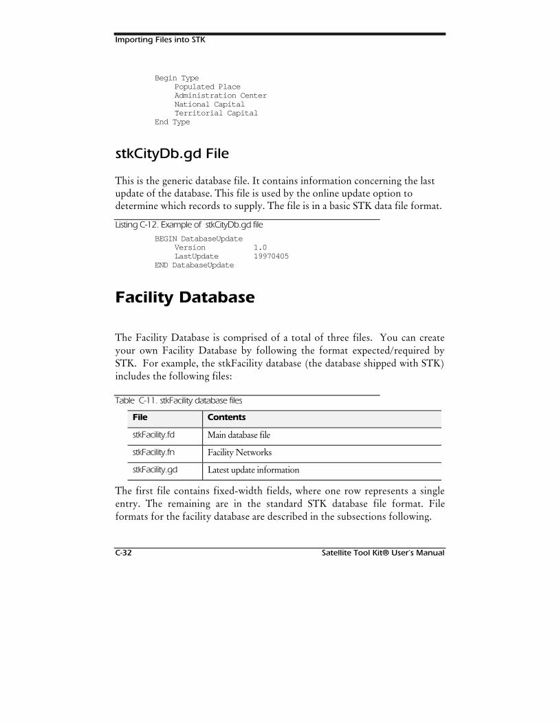
Importing Files into STK
C-32 Satellite Tool Kit® User’s Manual
Begin TypePopulated PlaceAdministration CenterNational CapitalTerritorial Capital
End Type
stkCityDb.gd File
This is the generic database file. It contains information concerning the lastupdate of the database. This file is used by the online update option todetermine which records to supply. The file is in a basic STK data file format.
Listing C-12. Example of stkCityDb.gd file
BEGIN DatabaseUpdateVersion 1.0LastUpdate 19970405
END DatabaseUpdate
Facility Database
The Facility Database is comprised of a total of three files. You can createyour own Facility Database by following the format expected/required bySTK. For example, the stkFacility database (the database shipped with STK)includes the following files:
Table C-11. stkFacility database files
File Contents
stkFacility.fd Main database file
stkFacility.fn Facility Networks
stkFacility.gd Latest update information
The first file contains fixed-width fields, where one row represents a singleentry. The remaining are in the standard STK database file format. Fileformats for the facility database are described in the subsections following.
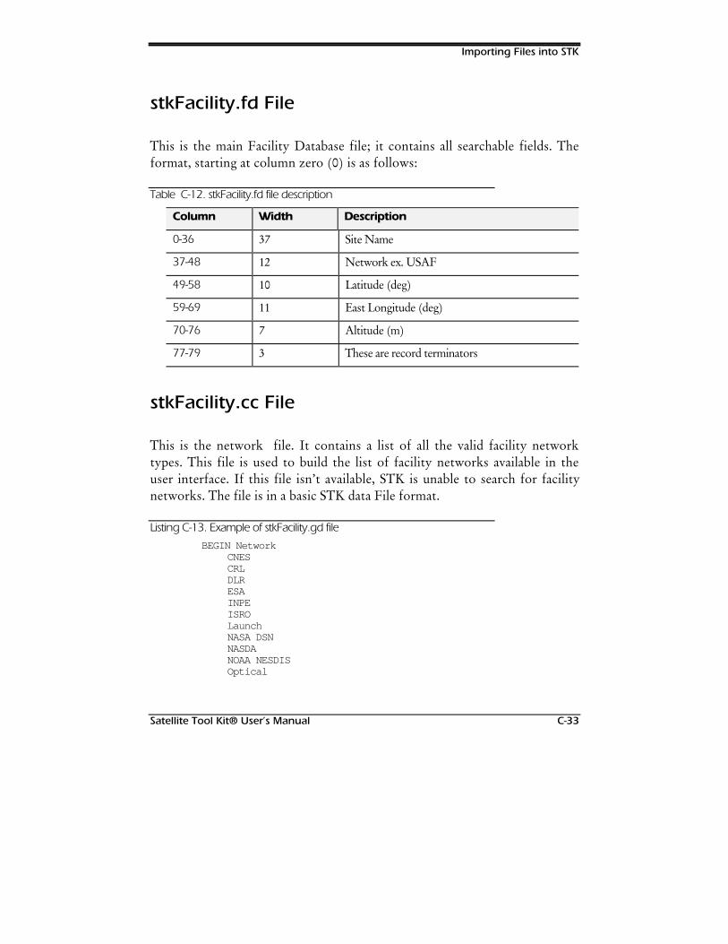
Importing Files into STK
Satellite Tool Kit® User’s Manual C-33
stkFacility.fd File
This is the main Facility Database file; it contains all searchable fields. Theformat, starting at column zero (0) is as follows:
Table C-12. stkFacility.fd file description
Column Width Description
0-36 37 Site Name
37-48 12 Network ex. USAF
49-58 10 Latitude (deg)
59-69 11 East Longitude (deg)
70-76 7 Altitude (m)
77-79 3 These are record terminators
stkFacility.cc File
This is the network file. It contains a list of all the valid facility networktypes. This file is used to build the list of facility networks available in theuser interface. If this file isn’t available, STK is unable to search for facilitynetworks. The file is in a basic STK data File format.
Listing C-13. Example of stkFacility.gd file
BEGIN NetworkCNESCRLDLRESAINPEISROLaunchNASA DSNNASDANOAA NESDISOptical
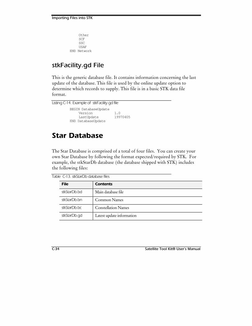
Importing Files into STK
C-34 Satellite Tool Kit® User’s Manual
OtherSCFSSCUSAF
END Network
stkFacility.gd File
This is the generic database file. It contains information concerning the lastupdate of the database. This file is used by the online update option todetermine which records to supply. This file is in a basic STK data fileformat.
Listing C-14. Example of stkFacility.gd file
BEGIN DatabaseUpdateVersion 1.0LastUpdate 19970405
END DatabaseUpdate
Star Database
The Star Database is comprised of a total of four files. You can create yourown Star Database by following the format expected/required by STK. Forexample, the stkStarDb database (the database shipped with STK) includesthe following files:
Table C-13. stkStarDb database files
File Contents
stkStarDb.bd Main database file
stkStarDb.bn Common Names
stkStarDb.bc Constellation Names
stkStarDb.gd Latest update information
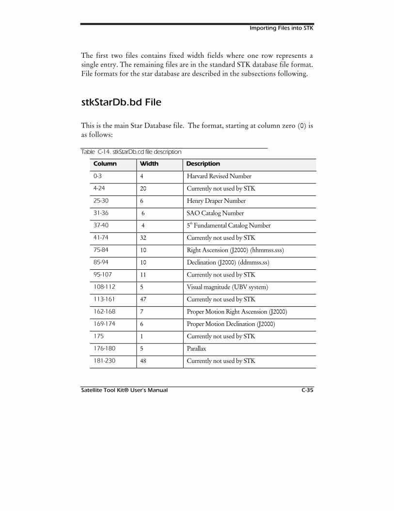
Importing Files into STK
Satellite Tool Kit® User’s Manual C-35
The first two files contains fixed width fields where one row represents asingle entry. The remaining files are in the standard STK database file format.File formats for the star database are described in the subsections following.
stkStarDb.bd File
This is the main Star Database file. The format, starting at column zero (0) isas follows:
Table C-14. stkStarDb.cd file description
Column Width Description
0-3 4 Harvard Revised Number
4-24 20 Currently not used by STK
25-30 6 Henry Draper Number
31-36 6 SAO Catalog Number
37-40 4 5th Fundamental Catalog Number
41-74 32 Currently not used by STK
75-84 10 Right Ascension (J2000) (hhmmss.sss)
85-94 10 Declination (J2000) (ddmmss.ss)
95-107 11 Currently not used by STK
108-112 5 Visual magnitude (UBV system)
113-161 47 Currently not used by STK
162-168 7 Proper Motion Right Ascension (J2000)
169-174 6 Proper Motion Declination (J2000)
175 1 Currently not used by STK
176-180 5 Parallax
181-230 48 Currently not used by STK
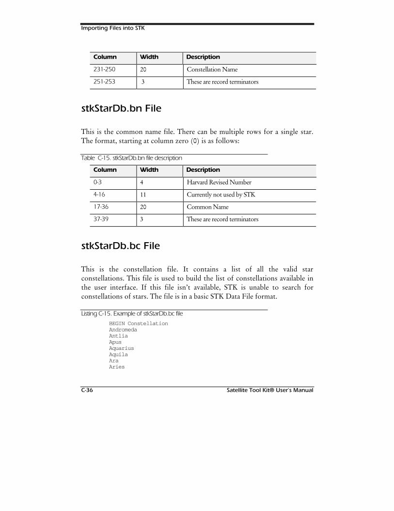
Importing Files into STK
C-36 Satellite Tool Kit® User’s Manual
Column Width Description
231-250 20 Constellation Name
251-253 3 These are record terminators
stkStarDb.bn File
This is the common name file. There can be multiple rows for a single star.The format, starting at column zero (0) is as follows:
Table C-15. stkStarDb.bn file description
Column Width Description
0-3 4 Harvard Revised Number
4-16 11 Currently not used by STK
17-36 20 Common Name
37-39 3 These are record terminators
stkStarDb.bc File
This is the constellation file. It contains a list of all the valid starconstellations. This file is used to build the list of constellations available inthe user interface. If this file isn’t available, STK is unable to search forconstellations of stars. The file is in a basic STK Data File format.
Listing C-15. Example of stkStarDb.bc file
BEGIN ConstellationAndromedaAntliaApusAquariusAquilaAraAries
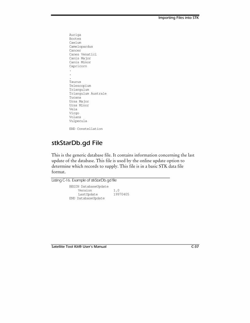
Importing Files into STK
Satellite Tool Kit® User’s Manual C-37
AurigaBootesCaelumCamelopardusCancerCanes VenaticiCanis MajorCanis MinorCapricorn...TaurusTelescopiumTriangulumTriangulum AustraleTucanaUrsa MajorUrsa MinorVelaVirgoVolansVulpecula
END Constellation
stkStarDb.gd File
This is the generic database file. It contains information concerning the lastupdate of the database. This file is used by the online update option todetermine which records to supply. This file is in a basic STK data fileformat.
Listing C-16. Example of stkStarDb.gd file
BEGIN DatabaseUpdateVersion 1.0LastUpdate 19970405
END DatabaseUpdate
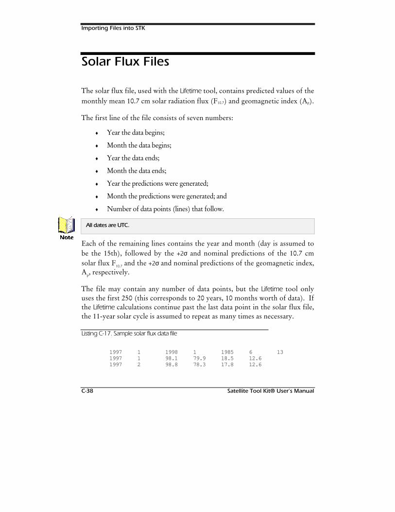
Importing Files into STK
C-38 Satellite Tool Kit® User’s Manual
Solar Flux Files
The solar flux file, used with the Lifetime tool, contains predicted values of themonthly mean 10.7 cm solar radiation flux (F10.7) and geomagnetic index (Ap).
The first line of the file consists of seven numbers:
♦ Year the data begins;
♦ Month the data begins;
♦ Year the data ends;
♦ Month the data ends;
♦ Year the predictions were generated;
♦ Month the predictions were generated; and
♦ Number of data points (lines) that follow.
All dates are UTC.
Each of the remaining lines contains the year and month (day is assumed tobe the 15th), followed by the +2σ and nominal predictions of the 10.7 cmsolar flux F10.7 and the +2σ and nominal predictions of the geomagnetic index,Ap, respectively.
The file may contain any number of data points, but the Lifetime tool onlyuses the first 250 (this corresponds to 20 years, 10 months worth of data). Ifthe Lifetime calculations continue past the last data point in the solar flux file,the 11-year solar cycle is assumed to repeat as many times as necessary.
Listing C-17. Sample solar flux data file
1997 1 1998 1 1985 6 131997 1 98.1 79.9 18.5 12.61997 2 98.8 78.3 17.8 12.6
1RWH

Importing Files into STK
Satellite Tool Kit® User’s Manual C-39
1997 3 100.0 77.4 16.9 12.61997 4 100.4 76.9 16.4 12.51997 5 98.3 76.6 16.6 12.61997 6 95.2 76.3 16.8 12.71997 7 92.3 76.0 17.0 12.51997 8 91.0 75.6 17.3 12.41997 9 91.4 75.1 17.6 12.11997 10 91.6 73.8 17.5 12.01997 11 91.2 73.2 17.3 11.71997 12 90.8 72.6 16.8 11.61998 1 90.2 72.9 16.0 11.5

Importing Files into STK
C-40 Satellite Tool Kit® User’s Manual
127(6
Satellite Tool Kit® User’s Manual D-1
Appendix D
HPOP TECHNICALNOTES
Technical Notes
Unpredictable Earth motions can’t be modeled at the present time. Theyinclude polar motion, irregular variations in the Earth’s rotation rate andcontinental drift. Polar motion causes the poles to wander in irregular circlesin a region approximately 30 m square, taking about a year to complete eachcircle. Irregular variations in the Earth’s rotation rate can change the lengthof the day by up to 0.25 milliseconds (ms) per year; however, such largechanges tend to cancel out over time, leaving a residual secular increase of 1.5ms per century. Continental drift occurs at rates of up to 5 centimeters (cm)per year.
Chapter Contents
Technical Notes...........................................................................................D-1
HPOP Values...............................................................................................D-2
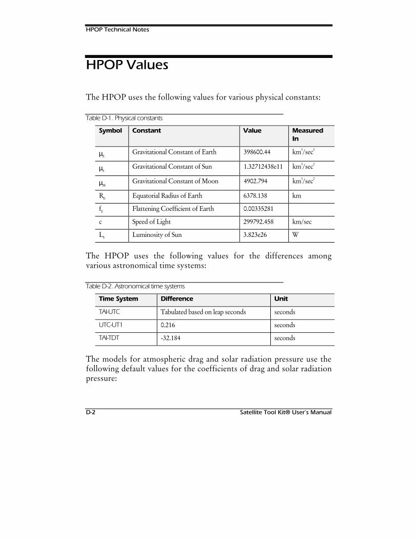
HPOP Technical Notes
D-2 Satellite Tool Kit® User’s Manual
HPOP Values
The HPOP uses the following values for various physical constants:
Table D-1. Physical constants
Symbol Constant Value MeasuredIn
µEGravitational Constant of Earth 398600.44 km3/sec2
µSGravitational Constant of Sun 1.32712438e11 km3/sec2
µMGravitational Constant of Moon 4902.794 km3/sec2
RE Equatorial Radius of Earth 6378.138 km
fE Flattening Coefficient of Earth 0.00335281
c Speed of Light 299792.458 km/sec
LS Luminosity of Sun 3.823e26 W
The HPOP uses the following values for the differences amongvarious astronomical time systems:
Table D-2. Astronomical time systems
Time System Difference Unit
TAI-UTC Tabulated based on leap seconds seconds
UTC-UT1 0.216 seconds
TAI-TDT -32.184 seconds
The models for atmospheric drag and solar radiation pressure use thefollowing default values for the coefficients of drag and solar radiationpressure:

HPOP Technical Notes
Satellite Tool Kit® User’s Manual D-3
Table D-3. Coefficients of drag and solar radiation pressure
Coefficient Value
cD (coeff of drag) 2.0
cR (coeff of solar radiation pressure) 2.0
These coefficients are defined by the following expressions for theaccelerations due to drag and solar radiation pressure.
Acceleration caused by drag is:
Acceleration caused by solar radiation is:
where:
cR = coefficient for solar radiation
cD = coefficient for drag
A = satellite cross-sectional area
M = satellite mass
ρ = atmosphere density
V = satellite speed relative to the atmosphere
LS = luminosity of the sun
c = speed of light
r = distance of satellite from sun
The modified Harris-Priester atmosphere density model uses the followingdefault values for the specified parameters:
( )
( )
a cA
M
V
a cA
M
L
cr
D D
R RS
≡
≡
ρ
π
2
2
2
8
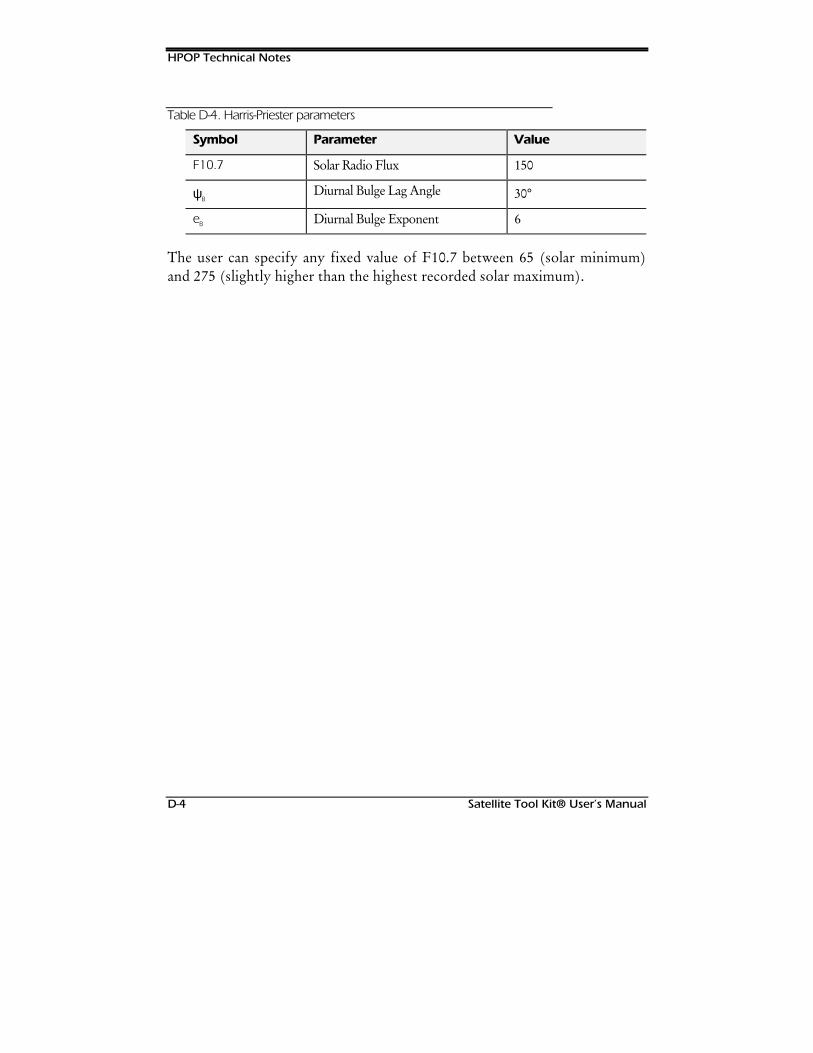
HPOP Technical Notes
D-4 Satellite Tool Kit® User’s Manual
Table D-4. Harris-Priester parameters
Symbol Parameter Value
F10.7 Solar Radio Flux 150
ψBDiurnal Bulge Lag Angle 30°
eB Diurnal Bulge Exponent 6
The user can specify any fixed value of F10.7 between 65 (solar minimum)and 275 (slightly higher than the highest recorded solar maximum).
Satellite Tool Kit® User’s Manual E-1
Appendix E
HIGH-RESOLUTION
MAPS TECHNICALNOTES
Overview
The High Resolution Maps module is based on the Relational WorldDatabank 2 (RWDB2). RWDB2 is available to the public in ASCII formatfrom the Earth Science Information Office of the U.S. Geological Survey.The RWDB2 database was designed for producing small-scale maps, not forapplications requiring high geodetic accuracy, such as navigation.
Chapter Contents
Definitions....................................................................................................E-2
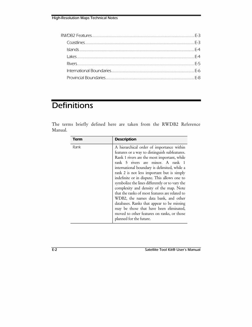
High-Resolution Maps Technical Notes
E-2 Satellite Tool Kit® User’s Manual
RWDB2 Features..........................................................................................E-3
Coastlines................................................................................................E-3
Islands.....................................................................................................E-4
Lakes.......................................................................................................E-4
Rivers.......................................................................................................E-5
International Boundaries.........................................................................E-6
Provincial Boundaries..............................................................................E-8
Definitions
The terms briefly defined here are taken from the RWDB2 ReferenceManual.
Term Description
Rank A hierarchical order of importance withinfeatures or a way to distinguish subfeatures.Rank 1 rivers are the most important, whilerank 5 rivers are minor. A rank 1international boundary is delimited, while arank 2 is not less important but is simplyindefinite or in dispute. This allows one tosymbolize the lines differently or to vary thecomplexity and density of the map. Notethat the ranks of most features are related toWDB2, the names data bank, and otherdatabases. Ranks that appear to be missingmay be those that have been eliminated,moved to other features on ranks, or thoseplanned for the future.
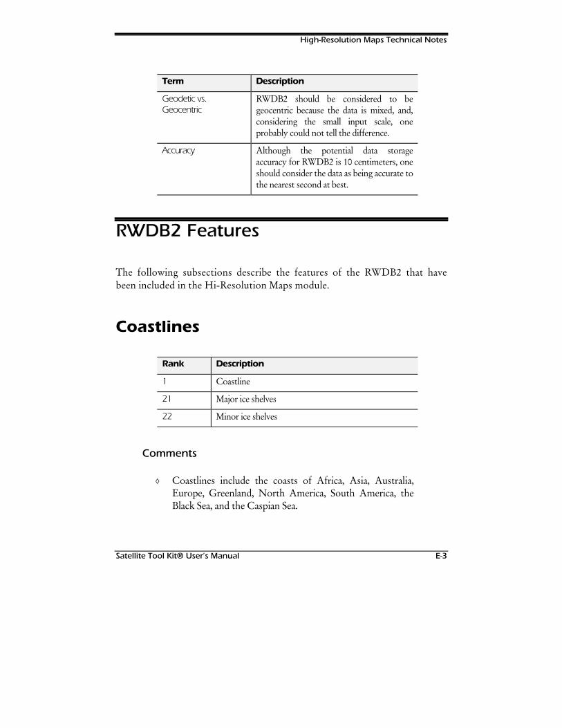
High-Resolution Maps Technical Notes
Satellite Tool Kit® User’s Manual E-3
Term Description
Geodetic vs.Geocentric
RWDB2 should be considered to begeocentric because the data is mixed, and,considering the small input scale, oneprobably could not tell the difference.
Accuracy Although the potential data storageaccuracy for RWDB2 is 10 centimeters, oneshould consider the data as being accurate tothe nearest second at best.
RWDB2 Features
The following subsections describe the features of the RWDB2 that havebeen included in the Hi-Resolution Maps module.
Coastlines
Rank Description
1 Coastline
21 Major ice shelves
22 Minor ice shelves
Comments
◊ Coastlines include the coasts of Africa, Asia, Australia,Europe, Greenland, North America, South America, theBlack Sea, and the Caspian Sea.
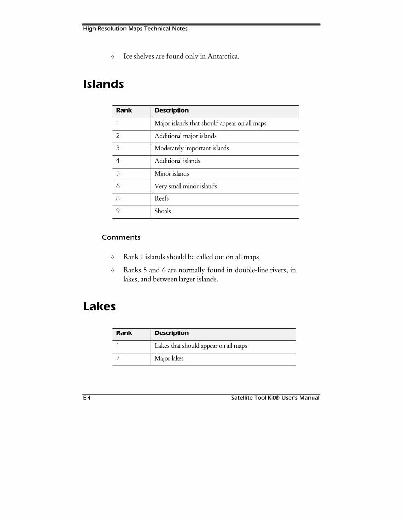
High-Resolution Maps Technical Notes
E-4 Satellite Tool Kit® User’s Manual
◊ Ice shelves are found only in Antarctica.
Islands
Rank Description
1 Major islands that should appear on all maps
2 Additional major islands
3 Moderately important islands
4 Additional islands
5 Minor islands
6 Very small minor islands
8 Reefs
9 Shoals
Comments
◊ Rank 1 islands should be called out on all maps
◊ Ranks 5 and 6 are normally found in double-line rivers, inlakes, and between larger islands.
Lakes
Rank Description
1 Lakes that should appear on all maps
2 Major lakes
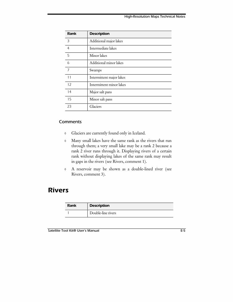
High-Resolution Maps Technical Notes
Satellite Tool Kit® User’s Manual E-5
Rank Description
3 Additional major lakes
4 Intermediate lakes
5 Minor lakes
6 Additional minor lakes
7 Swamps
11 Intermittent major lakes
12 Intermittent minor lakes
14 Major salt pans
15 Minor salt pans
23 Glaciers
Comments
◊ Glaciers are currently found only in Iceland.
◊ Many small lakes have the same rank as the rivers that runthrough them; a very small lake may be a rank 2 because arank 2 river runs through it. Displaying rivers of a certainrank without displaying lakes of the same rank may resultin gaps in the rivers (see Rivers, comment 1).
◊ A reservoir may be shown as a double-lined river (seeRivers, comment 3).
Rivers
Rank Description
1 Double-line rivers
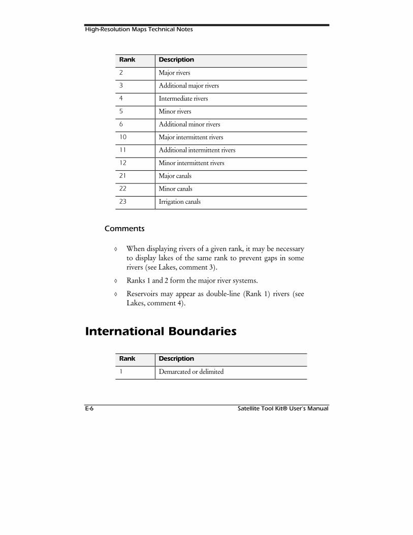
High-Resolution Maps Technical Notes
E-6 Satellite Tool Kit® User’s Manual
Rank Description
2 Major rivers
3 Additional major rivers
4 Intermediate rivers
5 Minor rivers
6 Additional minor rivers
10 Major intermittent rivers
11 Additional intermittent rivers
12 Minor intermittent rivers
21 Major canals
22 Minor canals
23 Irrigation canals
Comments
◊ When displaying rivers of a given rank, it may be necessaryto display lakes of the same rank to prevent gaps in somerivers (see Lakes, comment 3).
◊ Ranks 1 and 2 form the major river systems.
◊ Reservoirs may appear as double-line (Rank 1) rivers (seeLakes, comment 4).
International Boundaries
Rank Description
1 Demarcated or delimited

High-Resolution Maps Technical Notes
Satellite Tool Kit® User’s Manual E-7
Rank Description
2 Indefinite or in dispute
3 Lines of separation or sovereignty on land
4 Lines of separation or sovereignty in the sea
5 Other lines of separation or sovereignty in the sea.Represents one generalization when island jurisdictionmust be shown
6 Continental shelf boundary in Persian Gulf
7 Demilitarized zone lines in Israel
8 No defined line: tone guide for lines in Arabianpeninsula, Chad-Libya, and India-Pakistan
9 Selected claimed lines
50 Old Panama Canal Zone lines
51 Old N. Yemen-S. Yemen
52 Old Jordan-Iraq
53 Old Iraq-Saudi Arabia Neutral Zone lines
54 Old East Germany, West Germany, and Berlin lines
55 Old North-South Vietnam boundary
56 Old Vietnam DMZ lines
57 Old Kuwait-Saudi Neutral Zone lines
58 Old Oman-Yemen line of separation
Comments
◊ Status and/or rank is defined by the U.S. State Department.Other lines in dispute, indefinite, or lines of separation mayexist but were not input due to scale.
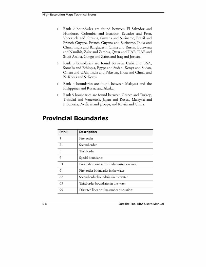
High-Resolution Maps Technical Notes
E-8 Satellite Tool Kit® User’s Manual
◊ Rank 2 boundaries are found between El Salvador andHonduras, Colombia and Ecuador, Ecuador and Peru,Venezuela and Guyana, Guyana and Suriname, Brazil andFrench Guyana, French Guyana and Suriname, India andChina, India and Bangladesh, China and Russia, Botswanaand Namibia, Zaire and Zambia, Qatar and UAE, UAE andSaudi Arabia, Congo and Zaire, and Iraq and Jordan.
◊ Rank 3 boundaries are found between Cuba and USA,Somalia and Ethiopia, Egypt and Sudan, Kenya and Sudan,Oman and UAE, India and Pakistan, India and China, andN. Korea and S. Korea.
◊ Rank 4 boundaries are found between Malaysia and thePhilippines and Russia and Alaska.
◊ Rank 5 boundaries are found between Greece and Turkey,Trinidad and Venezuela, Japan and Russia, Malaysia andIndonesia, Pacific island groups, and Russia and China.
Provincial Boundaries
Rank Description
1 First order
2 Second order
3 Third order
4 Special boundaries
54 Pre-unification German administration lines
61 First order boundaries in the water
62 Second order boundaries in the water
63 Third order boundaries in the water
99 Disputed lines or “lines under discussion”

High-Resolution Maps Technical Notes
Satellite Tool Kit® User’s Manual E-9
Comments
◊ Provincial boundaries are provided for the United Statesand Canada only.

High-Resolution Maps Technical Notes
E-10 Satellite Tool Kit® User’s Manual
127(6
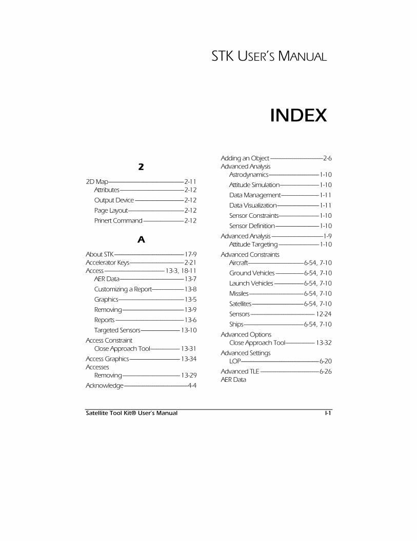
Satellite Tool Kit® User’s Manual I-1
STK USER’S MANUAL
INDEX
22D Map------------------------------------------------------2-11
Attributes----------------------------------------------2-12
Output Device -----------------------------------2-12
Page Layout----------------------------------------2-12
Prinert Command-----------------------------2-12
AAbout STK--------------------------------------------------17-9Accelerator Keys---------------------------------------2-21Access -------------------------------------------13-3, 18-11
AER Data----------------------------------------------13-7
Customizing a Report-----------------------13-8
Graphics-----------------------------------------------13-5
Removing--------------------------------------------13-9
Reports -------------------------------------------------13-6
Targeted Sensors---------------------------- 13-10
Access ConstraintClose Approach Tool--------------------- 13-31
Access Graphics------------------------------------ 13-34Accesses
Removing----------------------------------------- 13-29
Acknowledge----------------------------------------------4-4
Adding an Object --------------------------------------2-6Advanced Analysis
Astrodynamics------------------------------------1-10
Attitude Simulation----------------------------1-10
Data Management---------------------------1-11
Data Visualization------------------------------1-11
Sensor Constraints-----------------------------1-10
Sensor Definition-------------------------------1-10
Advanced Analysis -------------------------------------1-9Attitude Targeting -----------------------------1-10
Advanced ConstraintsAircraft----------------------------------------6-54, 7-10
Ground Vehicles --------------------6-54, 7-10
Launch Vehicles ---------------------6-54, 7-10
Missiles---------------------------------------6-54, 7-10
Satellites-------------------------------------6-54, 7-10
Sensors ---------------------------------------------- 12-24
Ships-------------------------------------------6-54, 7-10
Advanced OptionsClose Approach Tool--------------------- 13-32
Advanced SettingsLOP--------------------------------------------------------6-20
Advanced TLE ------------------------------------------6-26AER Data

Index
I-2 Satellite Tool Kit® User’s Manual
Access ---------------------------------------------------13-7
AER Report --------------------------------------------- 13-13Lighting--------------------------------------------- 13-13
AircraftAccess ---------------------------------------------------13-3
Basic Properties
Attitude -----------------------------------------------7-4
Route---------------------------------------------------7-2
Constraints
Advanced-----------------------------6-54, 7-10
Basic--------------------------------------------------6-47
Sun----------------------------------------------------6-50
Temporal-----------------------------------------6-52
Description------------------------------------------2-17
Graphics Properties
Attributes --------------------------------------------7-6
Display Times ------------------------------------7-8
Great Arc Propagator--------------------------7-2
Properties of-------------------------------------------7-1
Step Size--------------------------------------------------7-2
Swath------------------------------------------------- 13-23
Alignment at Epoch -------------------------------6-13All Of -----------------------------------------------------------18-7Allow Async--------------------------------------------------4-4Allow Connect --------------------------------------------4-4Allow Online Operations-------------------------4-5Altitude Range---------------------------------------------9-9Angle Unit ----------------------------------------------------5-9Angle-Off-Boresight, Custom Sensor----B-9Angular Rate----------------------------------6-48, 9-12Animating a Scenario-----------------------------3-18Animation-----------------------------------------------------5-4Animation & Vehicle Tracks------------------3-18Animation Time Steps -------------------------------3-4Antennas
Parabolic ----------------------------------------------12-4
Any Of --------------------------------------------------------18-7Apogee --------------------------------------------------- 14-10Apogee Altitude------------------------------------------6-5Apogee Radius--------------------------------------------6-5Application
Exiting the Application -------------------------2-3
IPC Preferences -------------------------------------4-3
Online Operations-------------------------------4-5
Properties of-------------------------------------------4-1
Save Prefs------------------------------------------------4-2
Applications, External-----------------------------2-152-16
Archive Date------------------------------------------ 14-13Area Exposed to Sun--------------------------- 13-16Area Targets
Access ---------------------------------------------------13-3
Attributes----------------------------------------------10-6
Basic Constraints--------------------------------10-7
Basic Properties
Boundary----------------------------------------10-2
Centroid ------------------------------------------10-3
Constraints-------------------------------------------10-7
Basic--------------------------------------------------10-7
Temporal-----------------------------------------10-9
Description------------------------------------------2-17
Graphics Properties
Attributes -----------------------------------------10-6
Temporal Constraints-----------------------10-9
Area to Mass Ratio------------------------6-16, 6-19Argument of Latitude--------------------------------6-7Argument of Perigee--------------------- 6-6, 6-23Assigned Targets------------------------6-37, 12-13At Least N---------------------------------------------------18-7Atmospheric Drag--------------------------1-12, D-2Attitude---------------------------------------------- 6-28, 7-4
Attitude Type --------------------------------------6-29

Index
Satellite Tool Kit® User’s Manual I-3
Integrated Attitude----------------------------6-35
Launch Vehicles------------------------------------8-6
Missiles-----------------------------------------------------8-6
Orientation Type -------------------------------6-34
Target Pointing ----------------------------------6-36
Attitude File Format --------------------------C-3, C-7Keywords-----------------------------------------------C-3
Attitude File, External------------------------7-6, 8-7Attitude Simulation----------------------------------1-10Attitude Targeting -----------------------------------1-10Attitude Type --------------------------------------------6-29Attributes--------------------------------6-41, 7-6, 10-6
Facilities----------------------------------------------------9-6
Graphs------------------------------------15-13, 16-9
Launch Vehicles------------------------------------8-7
Map----------------------------------------------------------3-5
Missiles-----------------------------------------------------8-7
Planets --------------------------------------------------11-4
Stars-------------------------------------------------------11-4
Targets-----------------------------------------------------9-6
Auto Propagate -----------------------14-12, 14-20Auto Save------------------------------------------------------4-2Auxiliary Database-----------------------------------5-12Average F10.7 -----------------------------------------6-16Axis Annotations----------------------------------- 15-18Az-El File Format ----------------------------------------C-8Az-El Mask--------------------------------------------------9-13
Facilities-------------------------------------------9-6, 9-8
Targets--------------------------------------------9-6, 9-8
Az-El Mask, Custom Sensor----------------------B-7Azimuth Angle ------------------------------6-48, 9-11Azimuth Rate --------------------------------------------9-12Azimuthal Equidistant Projection--------3-11
BB1950---------------------------------------------------------6-13
Background----------------------------------------------6-56Background,Map------------------------------------3-14Ballistic Propagator-------------------------------------8-3Barycentric Displacement ---------------------1-12Basic Constraints
Aircraft---------------------------------------------------6-47
Area Targets----------------------------------------10-7
Facilities ------------------------------------------------9-10
Ground Vehicles -------------------------------6-47
Launch Vehicles --------------------------------6-47
Missiles--------------------------------------------------6-47
Satellites------------------------------------------------6-47
Ships------------------------------------------------------6-47
Targets--------------------------------------------------9-10
Basic Fifth Fundamental Catalog----- 14-16Basic Properties ----------------------------------------2-16
Sensors -------------------------------------------------12-2
Basic Properties of a Constellation------18-6Bitmap File Format----------------------------------C-19Black Bodies----------------------------------------------1-12Blink on Select ------------------------------------------5-16Boresight
Fixed--------------------------------------------------- 12-14
Tracking--------------------------------------------- 12-14
BoundariesArea Targets----------------------------------------10-2
Browser Window------------------------------2-3, 2-4Bstar-------------------------------------------------------------6-23
C2-16
Cartesian Coordinate Type----------------------6-8Cartesian Position--------------------------- 9-4, 10-5CAT-----------------------See Close Approach ToolCentroid-----------------------------------------------------10-3
Cartesian----------------------------------------------10-5
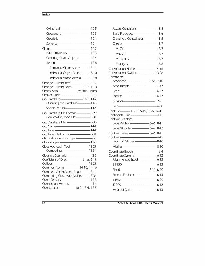
Index
I-4 Satellite Tool Kit® User’s Manual
Cylindrical --------------------------------------------10-5
Geocentric-------------------------------------------10-5
Geodetic ----------------------------------------------10-4
Spherical-----------------------------------------------10-4
Chain ----------------------------------------------------------18-2Basic Properties ----------------------------------18-3
Ordering Chain Objects------------------18-4
Reports -------------------------------------------------18-8
Complete Chain Access ----------- 18-11
Individual Object Access---------- 18-10
Individual Strand Access--------------18-8
Change Current Item-----------------------------3-17Change Current Point ----------------10-3, 12-8Charts, Strip--------------------------See Strip ChartsCircular Orbit---------------------------------------------6-15City Database---------------------------------14-1, 14-2
Querying the Database-------------------14-3
Search Results-------------------------------------14-4
City Database File Format---------------------C-29Country/City Type File ---------------------C-31
City Database Files ----------------------------------C-30City Name--------------------------------------------------14-4City Type ----------------------------------------------------14-4City Type File Format------------------------------C-31Classical Coordinate Type ------------------------6-5Clock Angles ---------------------------------------------12-3Close Approach Tool--------------------------- 13-29
Computing--------------------------------------- 13-34
Closing a Scenario--------------------------------------2-5Coefficient of Drag-----------------------6-16, 6-19Collision--------------------------------------------------- 13-29Common Name----------------------14-10, 14-16Complete Chain Access Report-------- 18-11Computing Close Approaches--------- 13-34Conic Sensors-------------------------------------------12-3Connection Method ---------------------------------4-4Constellation-----------------------18-2, 18-4, 18-5
Access Conditions -----------------------------18-8
Basic Properties ----------------------------------18-6
Creating a Constellation------------------18-5
Criteria---------------------------------------------------18-7
All Of-------------------------------------------------18-7
Any Of----------------------------------------------18-7
At Least N----------------------------------------18-7
Exactly N------------------------------------------18-8
Constellation Name----------------------------- 14-16Constellation, Walker -------------------------- 13-26Constraints
Advanced---------------------------------6-54, 7-10
Area Targets----------------------------------------10-7
Basic ------------------------------------------------------6-47
Satellite--------------------------------------------------6-47
Sensors ---------------------------------------------- 12-21
Sun --------------------------------------------------------6-50
Content--------------- 15-7, 15-15, 16-6, 16-11Continental Drift ----------------------------------------D-1Contour Graphics
Level Adding----------------------------6-46, 8-11
LevelAttributes -------------------------6-47, 8-12
Contour Levels------------------------------6-46, 8-11Contours----------------------------------------------------6-45
Launch Vehicles --------------------------------8-10
Missiles--------------------------------------------------8-10
Coordinate Epoch -------------------------------------6-4Coordinate Systems--------------------------------6-12
Alignment at Epoch -------------------------6-13
B1950---------------------------------------------------6-13
Fixed-------------------------------------------6-12, 6-29
Fmean Equinox---------------------------------6-13
Inertial ---------------------------------------------------6-29
J2000----------------------------------------------------6-12
Mean of Date-------------------------------------6-13
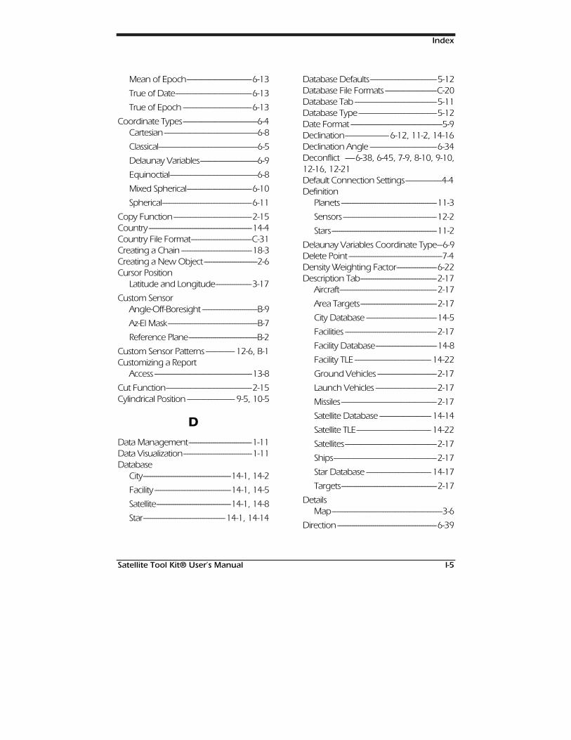
Index
Satellite Tool Kit® User’s Manual I-5
Mean of Epoch----------------------------------6-13
True of Date----------------------------------------6-13
True of Epoch ------------------------------------6-13
Coordinate Types---------------------------------------6-4Cartesian-------------------------------------------------6-8
Classical----------------------------------------------------6-5
Delaunay Variables------------------------------6-9
Equinoctial----------------------------------------------6-8
Mixed Spherical----------------------------------6-10
Spherical-----------------------------------------------6-11
Copy Function-----------------------------------------2-15Country ------------------------------------------------------14-4Country File Format--------------------------------C-31Creating a Chain -------------------------------------18-3Creating a New Object----------------------------2-6Cursor Position
Latitude and Longitude-------------------3-17
Custom SensorAngle-Off-Boresight -----------------------------B-9
Az-El Mask-----------------------------------------------B-7
Reference Plane------------------------------------B-2
Custom Sensor Patterns --------------- 12-6, B-1Customizing a Report
Access ---------------------------------------------------13-8
Cut Function---------------------------------------------2-15Cylindrical Position ------------------------- 9-5, 10-5
DData Management---------------------------------1-11Data Visualization------------------------------------1-11Database
City----------------------------------------------14-1, 14-2
Facility ----------------------------------------14-1, 14-5
Satellite---------------------------------------14-1, 14-8
Star-------------------------------------------14-1, 14-14
Database Defaults-----------------------------------5-12Database File Formats ---------------------------C-20Database Tab -------------------------------------------5-11Database Type-----------------------------------------5-12Date Format ------------------------------------------------5-9Declination-----------------------6-12, 11-2, 14-16Declination Angle -----------------------------------6-34Deconflict -----6-38, 6-45, 7-9, 8-10, 9-10,12-16, 12-21Default Connection Settings-------------------4-4Definition
Planets --------------------------------------------------11-3
Sensors -------------------------------------------------12-2
Stars-------------------------------------------------------11-2
Delaunay Variables Coordinate Type---6-9Delete Point -------------------------------------------------7-4Density Weighting Factor---------------------6-22Description Tab----------------------------------------2-17
Aircraft---------------------------------------------------2-17
Area Targets----------------------------------------2-17
City Database -------------------------------------14-5
Facilities ------------------------------------------------2-17
Facility Database--------------------------------14-8
Facility TLE ---------------------------------------- 14-22
Ground Vehicles -------------------------------2-17
Launch Vehicles --------------------------------2-17
Missiles--------------------------------------------------2-17
Satellite Database --------------------------- 14-14
Satellite TLE--------------------------------------- 14-22
Satellites------------------------------------------------2-17
Ships------------------------------------------------------2-17
Star Database ---------------------------------- 14-17
Targets--------------------------------------------------2-17
DetailsMap----------------------------------------------------------3-6
Direction ----------------------------------------------------6-39
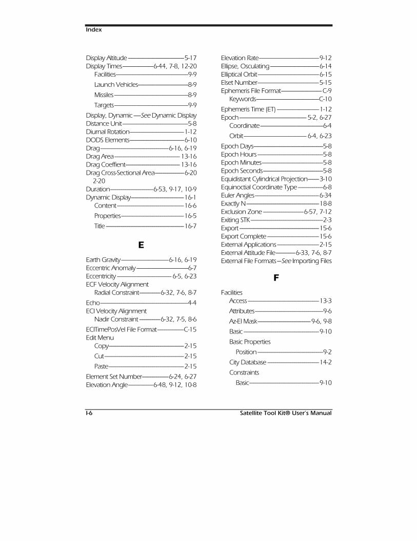
Index
I-6 Satellite Tool Kit® User’s Manual
Display Altitude ----------------------------------------5-17Display Times----------------------6-44, 7-8, 12-20
Facilities----------------------------------------------------9-9
Launch Vehicles------------------------------------8-9
Missiles-----------------------------------------------------8-9
Targets-----------------------------------------------------9-9
Display, Dynamic -----See Dynamic DisplayDistance Unit-----------------------------------------------5-8Diurnal Rotation---------------------------------------1-12DODS Elements---------------------------------------6-10Drag-------------------------------------------------6-16, 6-19Drag Area----------------------------------------------- 13-16Drag Coeffient--------------------------------------- 13-16Drag Cross-Sectional Area---------------------6-20
2-20Duration-------------------------------6-53, 9-17, 10-9Dynamic Display--------------------------------------16-1
Content------------------------------------------------16-6
Properties---------------------------------------------16-5
Title --------------------------------------------------------16-7
EEarth Gravity----------------------------------6-16, 6-19Eccentric Anomaly -------------------------------------6-7Eccentricity --------------------------------------- 6-5, 6-23ECF Velocity Alignment
Radial Constraint---------------6-32, 7-6, 8-7
Echo---------------------------------------------------------------4-4ECI Velocity Alignment
Nadir Constraint ---------------6-32, 7-5, 8-6
ECITimePosVel File Format-------------------C-15Edit Menu
Copy------------------------------------------------------2-15
Cut---------------------------------------------------------2-15
Paste------------------------------------------------------2-15
Element Set Number-------------------6-24, 6-27Elevation Angle------------------6-48, 9-12, 10-8
Elevation Rate-------------------------------------------9-12Ellipse, Osculating-----------------------------------6-14Elliptical Orbit--------------------------------------------6-15Elset Number--------------------------------------------5-15Ephemeris File Format----------------------------- C-9
Keywords---------------------------------------------C-10
Ephemeris Time (ET) ------------------------------1-12Epoch------------------------------------------------ 5-2, 6-27
Coordinate---------------------------------------------6-4
Orbit--------------------------------------------- 6-4, 6-23
Epoch Days--------------------------------------------------5-8Epoch Hours -----------------------------------------------5-8Epoch Minutes--------------------------------------------5-8Epoch Seconds-------------------------------------------5-8Equidistant Cylindrical Projection--------3-10Equinoctial Coordinate Type ------------------6-8Euler Angles----------------------------------------------6-34Exactly N----------------------------------------------------18-8Exclusion Zone -----------------------------6-57, 7-12Exiting STK----------------------------------------------------2-3Export ---------------------------------------------------------15-6Export Complete -------------------------------------15-6External Applications ------------------------------2-15External Attitude File--------------6-33, 7-6, 8-7External File Formats---See Importing Files
FFacilities
Access ---------------------------------------------------13-3
Attributes-------------------------------------------------9-6
Az-El Mask--------------------------------------9-6, 9-8
Basic ------------------------------------------------------9-10
Basic Properties
Position -----------------------------------------------9-2
City Database -------------------------------------14-2
Constraints
Basic--------------------------------------------------9-10
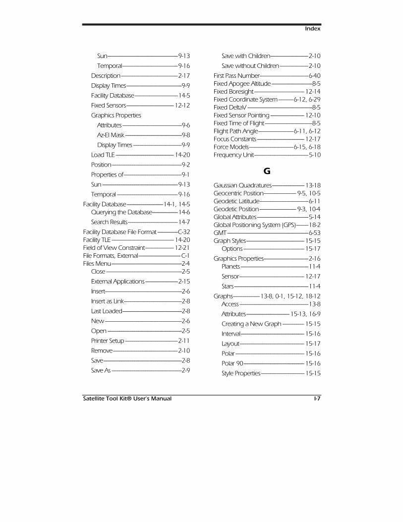
Index
Satellite Tool Kit® User’s Manual I-7
Sun----------------------------------------------------9-13
Temporal-----------------------------------------9-16
Description------------------------------------------2-17
Display Times-----------------------------------------9-9
Facility Database--------------------------------14-5
Fixed Sensors----------------------------------- 12-12
Graphics Properties
Attributes --------------------------------------------9-6
Az-El Mask ------------------------------------------9-8
Display Times ------------------------------------9-9
Load TLE ------------------------------------------- 14-20
Position----------------------------------------------------9-2
Properties of-------------------------------------------9-1
Sun --------------------------------------------------------9-13
Temporal ---------------------------------------------9-16
Facility Database---------------------------14-1, 14-5Querying the Database-------------------14-6
Search Results-------------------------------------14-7
Facility Database File Format ---------------C-32Facility TLE ---------------------------------------------- 14-20Field of View Constraint--------------------- 12-21File Formats, External-------------------------------C-1Files Menu----------------------------------------------------2-4
Close --------------------------------------------------------2-5
External Applications ------------------------2-15
Insert---------------------------------------------------------2-6
Insert as Link-------------------------------------------2-8
Last Loaded--------------------------------------------2-8
New---------------------------------------------------------2-6
Open -------------------------------------------------------2-5
Printer Setup ---------------------------------------2-11
Remove------------------------------------------------2-10
Save----------------------------------------------------------2-8
Save As ----------------------------------------------------2-9
Save with Children----------------------------2-10
Save without Children---------------------2-10
First Pass Number------------------------------------6-40Fixed Apogee Altitude ------------------------------8-5Fixed Boresight ------------------------------------- 12-14Fixed Coordinate System-----------6-12, 6-29Fixed DeltaV ------------------------------------------------8-5Fixed Sensor Pointing ------------------------- 12-10Fixed Time of Flight -----------------------------------8-5Flight Path Angle--------------------------6-11, 6-12Focus Constants ----------------------------------- 12-17Force Models---------------------------------6-15, 6-18Frequency Unit----------------------------------------5-10
GGaussian Quadratures------------------------ 13-18Geocentric Position------------------------ 9-5, 10-5Geodetic Latitude------------------------------------6-11Geodetic Position--------------------------- 9-3, 10-4Global Attributes--------------------------------------5-14Global Positioning System (GPS)---------18-2GMT ------------------------------------------------------------6-53Graph Styles------------------------------------------- 15-15
Options --------------------------------------------- 15-17
Graphics Properties---------------------------------2-16Planets --------------------------------------------------11-4
Sensor------------------------------------------------ 12-17
Stars-------------------------------------------------------11-4
Graphs--------------------13-8, 0-1, 15-12, 18-12Access ---------------------------------------------------13-8
Attributes--------------------------------15-13, 16-9
Creating a New Graph ---------------- 15-15
Interval----------------------------------------------- 15-16
Layout------------------------------------------------ 15-17
Polar--------------------------------------------------- 15-16
Polar 90--------------------------------------------- 15-16
Style Properties-------------------------------- 15-15
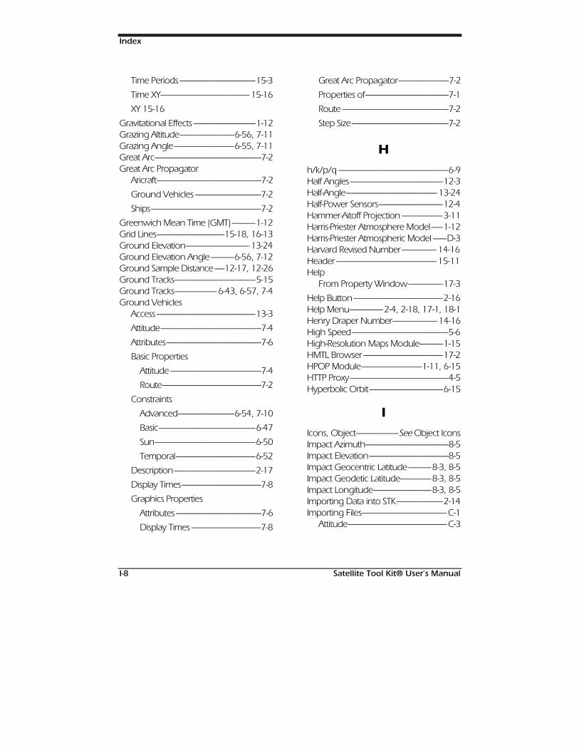
Index
I-8 Satellite Tool Kit® User’s Manual
Time Periods ---------------------------------------15-3
Time XY---------------------------------------------- 15-16
XY 15-16
Gravitational Effects --------------------------------1-12Grazing Altitude----------------------------6-56, 7-11Grazing Angle-------------------------------6-55, 7-11Great Arc-------------------------------------------------------7-2Great Arc Propagator
Aricraft------------------------------------------------------7-2
Ground Vehicles ----------------------------------7-2
Ships---------------------------------------------------------7-2
Greenwich Mean Time (GMT)------------1-12Grid Lines-----------------------------------15-18, 16-13Ground Elevation--------------------------------- 13-24Ground Elevation Angle ------------6-56, 7-12Ground Sample Distance -----12-17, 12-26Ground Tracks------------------------------------------5-15Ground Tracks----------------------6-43, 6-57, 7-4Ground Vehicles
Access ---------------------------------------------------13-3
Attitude----------------------------------------------------7-4
Attributes-------------------------------------------------7-6
Basic Properties
Attitude -----------------------------------------------7-4
Route---------------------------------------------------7-2
Constraints
Advanced-----------------------------6-54, 7-10
Basic--------------------------------------------------6-47
Sun----------------------------------------------------6-50
Temporal-----------------------------------------6-52
Description------------------------------------------2-17
Display Times-----------------------------------------7-8
Graphics Properties
Attributes --------------------------------------------7-6
Display Times ------------------------------------7-8
Great Arc Propagator--------------------------7-2
Properties of-------------------------------------------7-1
Route -------------------------------------------------------7-2
Step Size--------------------------------------------------7-2
Hh/k/p/q ---------------------------------------------------------6-9Half Angles------------------------------------------------12-3Half-Angle----------------------------------------------- 13-24Half-Power Sensors---------------------------------12-4Hammer-Aitoff Projection ---------------------3-11Harris-Priester Atmosphere Model------1-12Harris-Priester Atmospheric Model -------D-3Harvard Revised Number------------------ 14-16Header ---------------------------------------------------- 15-11Help
From Property Window------------------17-3
Help Button ----------------------------------------------2-16Help Menu-----------------2-4, 2-18, 17-1, 18-1Henry Draper Number----------------------- 14-16High Speed--------------------------------------------------5-6High-Resolution Maps Module------------1-15HMTL Browser -----------------------------------------17-2HPOP Module-------------------------------1-11, 6-15HTTP Proxy---------------------------------------------------4-5Hyperbolic Orbit--------------------------------------6-15
IIcons, Object----------------------See Object IconsImpact Azimuth-------------------------------------------8-5Impact Elevation-----------------------------------------8-5Impact Geocentric Latitude------------8-3, 8-5Impact Geodetic Latitude----------------8-3, 8-5Impact Longitude------------------------------8-3, 8-5Importing Data into STK------------------------2-14Importing Files-------------------------------------------- C-1
Attitude--------------------------------------------------- C-3
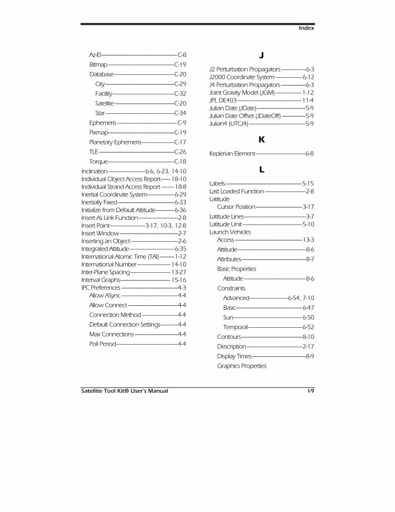
Index
Satellite Tool Kit® User’s Manual I-9
Az-El---------------------------------------------------------C-8
Bitmap--------------------------------------------------C-19
Database----------------------------------------------C-20
City ----------------------------------------------------C-29
Facility-----------------------------------------------C-32
Satellite ---------------------------------------------C-20
Star----------------------------------------------------C-34
Ephemeris ---------------------------------------------C-9
Pixmap--------------------------------------------------C-19
Planetary Ephemeris-------------------------C-17
TLE---------------------------------------------------------C-26
Torque--------------------------------------------------C-18
Inclination----------------------------6-6, 6-23, 14-10Individual Object Access Report------- 18-10Individual Strand Access Report ----------18-8Inertial Coordinate System--------------------6-29Inertially Fixed-------------------------------------------6-33Initialize from Default Attitude--------------6-36Insert As Link Function------------------------------2-8Insert Point---------------------------3-17, 10-3, 12-8Insert Window--------------------------------------------2-7Inserting an Object------------------------------------2-6Integrated Attitude----------------------------------6-35International Atomic Time (TAI) -----------1-12International Number------------------------- 14-10Inter-Plane Spacing------------------------------ 13-27Interval Graphs-------------------------------------- 15-16IPC Preferences -------------------------------------------4-3
Allow ASync-------------------------------------------4-4
Allow Connect --------------------------------------4-4
Connection Method ---------------------------4-4
Default Connection Settings-------------4-4
Max Connections---------------------------------4-4
Poll Period-----------------------------------------------4-4
JJ2 Perturbation Propagators-------------------6-3J2000 Coordinate System --------------------6-12J4 Perturbation Propagators-------------------6-3Joint Gravity Model (JGM)--------------------1-12JPL DE403-------------------------------------------------11-4Julian Date (JDate)-------------------------------------5-9Julian Date Offset (JDateOff) ------------------5-9Julian4 (UTCJ4)-------------------------------------------5-9
KKeplerian Element--------------------------------------6-8
LLabels----------------------------------------------------------5-15Last Loaded Function -------------------------------2-8Latitude
Cursor Position-----------------------------------3-17
Latitude Lines-----------------------------------------------3-7Latitude Unit ---------------------------------------------5-10Launch Vehicles
Access ---------------------------------------------------13-3
Attitude----------------------------------------------------8-6
Attributes-------------------------------------------------8-7
Basic Properties
Attitude -----------------------------------------------8-6
Constraints
Advanced-----------------------------6-54, 7-10
Basic--------------------------------------------------6-47
Sun----------------------------------------------------6-50
Temporal-----------------------------------------6-52
Contours----------------------------------------------8-10
Description------------------------------------------2-17
Display Times-----------------------------------------8-9
Graphics Properties
Index
I-10 Satellite Tool Kit® User’s Manual
Attributes --------------------------------------------8-7
Contours -----------------------------------------8-10
Display Times ------------------------------------8-9
Propagator---------------------------------------------8-3
Properties of-------------------------------------------8-1
Step Size--------------------------------------------------8-2
Swath------------------------------------------------- 13-23
Layout-----------------------------------------15-17, 16-13Leading Ground Track --------------------------6-44Leading Orbit Track --------------------------------6-44Level Adding----------------------------------6-46, 8-11Level Attributes------------------------------6-47, 8-12Lifetime---------------------------------------------------- 13-14Lifetime Module---------------------------------------1-14Lighting--------------------------------------------------- 13-11
AER Report --------------------------------------- 13-13
Sun --------------------------------------------------------5-16
Time Data----------------------------------------- 13-13
Lighting Constraints---------------------6-52, 9-16Line of Sight------------------------6-49, 9-13, 10-8Link -----------------------------------------------------------------2-8Lists --------------------------------------------------------------2-20Load Method--------------------------------------------6-25
Auto Load--------------------------------------------6-25
File Insert----------------------------------------------6-25
File Load-----------------------------------------------6-25
Online Load----------------------------------------6-25
Load TLE ------------------------------------------------- 14-18Load TLE
Open Database-----------------14-19, 14-21
Local Apparent-------------------6-53, 9-17, 10-9Local Gregorian (LCLG)----------------------------5-8Local Julian (LCLJ) -------------------------------------5-8Longitude
Cursor Position-----------------------------------3-17
Longitude Lines ------------------------------------------3-7Longitude of the Ascending Node-------6-6
Longitude Unit-----------------------------------------5-10Long-term Orbit Predictor--------------See LOPLoop at Time------------------------------------------------5-5LOP--------------------------------------------------------------6-18
Advanced Settings ----------------------------6-20
LOP Module----------------------------------------------1-13Lunar Elevation Angle-----------------6-51, 9-15Lunar Exclusion Angle ----6-51, 6-52, 9-15,12-22, 12-23Lunar Gravity---------------------------------6-17, 6-20
MMagnitude ------------------------------------------------11-2Making Choices in STK---------------------------2-18Map
Azimuthal Equidistant ----------------------3-11
Details ------------------------------------------------------3-6
Equidistant Cylindrical----------------------3-10
Hammer-Aitoff------------------------------------3-11
Mercator ----------------------------------------------3-10
Miller------------------------------------------------------3-11
Mollweide--------------------------------------------3-11
Orthographic -------------------------------------3-11
Perspective ------------------------------------------3-10
Projections----------------------------------------------3-9
Sinusoidal---------------------------------------------3-11
Stereographic-------------------------------------3-11
Text Annotation---------------------------------3-15
Map Attributes---------------------------------------------3-5Scroll Bars------------------------------------------------3-6
Show Status Bar------------------------------------3-6
Show Terrain Regions-------------------------3-6
Show Tool Bar---------------------------------------3-6
Map Background------------------------------------3-14Map Details Tab------------------------------------------3-6

Index
Satellite Tool Kit® User’s Manual I-11
Map ProjectionCenter Point----------------------------------------3-13
Map Projections------------------------------------------3-9Map Properties--------------------------------------------3-5
Map Attributes---------------------------------------3-5
Map Background------------------------------3-14
Map Details --------------------------------------------3-6
Map Projection--------------------------------------3-9
Text Annotation---------------------------------3-15
Map Properties Button------------------------------3-5Map Window-------------------------------------3-1, 3-2
Animation Steps------------------------------------3-4
Map Properties Button------------------------3-5
Scroll Bars------------------------------------------------3-6
Status Area-------------------------------------------3-17
Status Bar------------------------------------------------3-6
Tool Bar------------------------------------------3-3, 3-6
Markers, Turn--------------------------------------------5-15Mass -----------------------------------6-20, 6-40, 13-16Mass Unit ------------------------------------------------------5-9Max Connections---------------------------------------4-4Max TLE Limit--------------------------------------------6-25Maximum Degree------------------------6-16, 6-19Maximum Drag Altitude------------------------6-22Maximum Order---------------------------6-16, 6-19Mean Anomaly ------------------------------- 6-7, 6-23Mean Equinox True Equator---------------6-13Mean Longitude-----------------------------------------6-9Mean Motion--------------------------------------------6-23Mean Motion Dot-----------------------------------6-23Mean of Date-------------------------------------------6-13Mean of Epoch----------------------------------------6-13Menu
Edit---------------------------------------------------------2-15
Files-----------------------------------------------------------2-4
Help-------------------------------------------------------2-18
Tools------------------------------------------------------2-17
Windows---------------------------------------------2-17
Mercator Projection--------------------------------3-10Meta Keys --------------------------------------------------2-21Mid-Point----------------------------------------------------6-27Miller Projection ---------------------------------------3-11Missiles
Access ---------------------------------------------------13-3
Attitude----------------------------------------------------8-6
Attributes-------------------------------------------------8-7
Basic Properties
Attitude -----------------------------------------------8-6
Constraints
Advanced-----------------------------6-54, 7-10
Basic--------------------------------------------------6-47
Sun----------------------------------------------------6-50
Temporal-----------------------------------------6-52
Contours----------------------------------------------8-10
Description------------------------------------------2-17
Display Times-----------------------------------------8-9
Graphics Properties
Attributes --------------------------------------------8-7
Contours -----------------------------------------8-10
Display Times ------------------------------------8-9
Propagator---------------------------------------------8-3
Properties of-------------------------------------------8-1
Step Size--------------------------------------------------8-2
Swath------------------------------------------------- 13-23
Mission----------------------------------------------------- 14-10Mission Elapsed (MisElap) ------------------------5-9Mixed Spherical Coordinate Type ------6-10Modify Point------------------------3-17, 10-3, 12-8Mollweide Projection -----------------------------3-11Motion Dot Dot---------------------------------------6-23MSGP4
Element Set Number -----------------------6-24
Index
I-12 Satellite Tool Kit® User’s Manual
TLE Load ----------------------------------------------6-24
MSGP4 Propagator---------------------------------6-22Multiple Instance--------------------------------------15-9
NNadir Alignment
ECF Velocity Constraint -------------------6-30
ECI Velocity Constraint---------------------6-30
Orbit Normal Constraint------------------6-31
Sun Constraint------------------------------------6-31
Network-----------------------------------------------------14-7New Objects------------------------------------------------2-6Nonorbiting Satellites --------------------------------6-1Nonorbiting Vehicles -----------------------7-1, 8-1Nutation-----------------------------------------------------1-12
OObject Description14-5, 14-8, 14-14, 14-17, 14-22Object Icons-------------------------------------------------2-5Object Menu-----------------------------------------------2-5Objects
Aircraft------------------------------------------------------7-1
Describing -------------------------------------------2-17
Facility ------------------------------------------------------9-1
Ground Vehicles ----------------------------------7-1
Inserting --------------------------------------------------2-6
Inserting as Links-----------------------------------2-8
Missiles-----------------------------------------------------8-1
New---------------------------------------------------------2-6
Planets --------------------------------------------------11-1
Properties---------------------------------------------2-15
Removing--------------------------------------------2-10
Satellites---------------------------------------------------6-1
Saving------------------------------------------------------2-8
Selecting Multiple ------------------------------2-18
Sensors -------------------------------------------------12-1
Ships---------------------------------------------------------7-1
Stars-------------------------------------------------------11-1
Target-------------------------------------------------------9-1
Oblateness Correction------------------------ 13-19Obtain Archived Database ---------------- 14-13Official Name----------------------------------------- 14-10OK Button -------------------------------------------------2-16On-Line Manuals-------------------------------------17-9Online Operations-------------------------------------4-5Online Update-------------------------------------- 14-12Online Updates ---------------------------------------17-9Opening a Scenario----------------------------------2-5Option Menus------------------------------------------2-20Orbit Count Limit---------------------------------- 13-18Orbit Epoch ------------------------------------- 6-4, 6-23Orbit Lifetime------------------------------See LifetimeOrbiting Satellites----------------------------------------6-1Orbits ----------------------------------------------------------5-15Orbits per Calculation ------------------------- 13-18Ordering Chain Objects------------------------18-4Orientation Type -------------------------------------6-34Orthographic Projection-----------------------3-11Osculating Ellipse ------------------------------------6-14Output Attitude File--------------------------------6-36Output Device -----------------------------------------2-12Owner----------------------------------------------------- 14-10Owner/Mission File Format -----------------C-24
PPage Layout-----------------------------------2-12, 2-14Pair-wise Analysis -----------------------18-2, 18-10Parabolic Antennas---------------------------------12-4Parabolic Orbit------------------------------------------6-15Parallax -------------------------------------------------------11-3Pass--------------------------------------------------------------6-42Pass Break--------------------------------------------------6-38Pass Labels-------------------------------------------------5-15

Index
Satellite Tool Kit® User’s Manual I-13
Paste Function------------------------------------------2-15Penumbra -----------------------------------5-17, 13-12Perigee ---------------------------------------------------- 14-10Perigee Altitude-------------------------------------------6-5Perigee Radius---------------------------------------------6-5Period------------------------------------------------------- 14-10Persistence---------------------------------------------- 12-19Perspective Projection----------------------------3-10Physical Data---------------------------------------------6-20Pitch-------------------------------------------------------------6-34Pixmap File Format---------------------------------C-19Planetary Ephemeris File Format--------C-17Planets --------------------------------------------------------11-1
Access ---------------------------------------------------13-3
Attributes----------------------------------------------11-4
Basic Properties
Definition-----------------------------------------11-3
Definition---------------------------------------------11-3
Description------------------------------------------2-17
Graphics Properties---------------------------11-4
Attributes -----------------------------------------11-4
Properties of----------------------------------------11-1
PointingTarget Times ------------------------------------ 12-15
Pointing a Sensor ------------------------------------12-9Polar 90 Graphs------------------------------------ 15-16Polar Graphs------------------------------------------ 15-16Polar Motion-----------------------------------------------D-1Polar Plot-------------------------------------------------------B-3Poll Period-----------------------------------------------------4-4Population-------------------------------------------------14-4Port-----------------------------------------------------------------4-5Posigrade------------------------------------------------------6-9Position
Cartesian-------------------------------------------------9-4
Cylindrical -----------------------------------------------9-5
Facilities----------------------------------------------------9-2
Geocentric----------------------------------------------9-5
Geodetic-------------------------------------------------9-3
Spherical--------------------------------------------------9-4
Targets-----------------------------------------------------9-2
Power Unit---------------------------------------------------5-9Precessing, Secularly-------------------------------6-15Precession--------------------------------------------------1-12Printer Command-----------------------------------2-12Printer Setup ---------------------------------------------2-11
2D Map------------------------------------------------2-11
Attributes----------------------------------------------2-14
Page Layout----------------------------------------2-14
Reports & Graphs------------------------------2-13
Projection------------------------------------------------ 12-18Azimuthal Equidistant ----------------------3-11
Equidistant Cylindrical----------------------3-10
Hammer-Aitoff------------------------------------3-11
Mercator ----------------------------------------------3-10
Miller------------------------------------------------------3-11
Mollweide--------------------------------------------3-11
Orthographic -------------------------------------3-11
Perspective ------------------------------------------3-10
Sinusoidal---------------------------------------------3-11
Stereographic-------------------------------------3-11
Projection, Map ------------------------------------------3-9Propagation Delay----------------------------------9-13Propagators
Ballistic------------------------------------------------------8-3
Great Arc-------------------------------------------------7-2
J2 Perturbation--------------------------------------6-3
J4 Perturbation--------------------------------------6-3
MSGP4 -------------------------------------------------6-22
STK External-----------------------------------------6-27
Two-Body-----------------------------------------------6-3
Index
I-14 Satellite Tool Kit® User’s Manual
Proper Motion------------------------------------------11-2Properties
Dynamic Display--------------------------------16-5
Reports -------------------------------------------------15-6
Strip Charts --------------------------------------- 16-10
Properties Menu-----------------------------------------2-4Basic ------------------------------------------------------2-16
Constraints-------------------------------------------2-16
Graphics-----------------------------------------------2-16
Properties of a(n) . . .STK Application--------------------------------------4-1
Properties of a(n) …Aircraft------------------------------------------------------7-1
Facility ------------------------------------------------------9-1
Ground Vehicle------------------------------------7-1
Launch Vehicle -------------------------------------8-1
Missile-------------------------------------------------------8-1
Planet----------------------------------------------------11-1
Satellite-----------------------------------------------------6-1
Scenario --------------------------------------------------0-1
Sensor---------------------------------------------------12-1
Ship-----------------------------------------------------------7-1
Star---------------------------------------------------------11-1
Target-------------------------------------------------------9-1
Properties, Object------------------------------------2-15Property Windows----------------------------------2-16
Basic ------------------------------------------------------2-16
Chain------------------------------------------------18-3
Constellation ----------------------------------18-6
Constraints-------------------------------------------2-16
Graphics-----------------------------------------------2-16
Help Button ----------------------------------------17-3
How to Use-----------------------------------------2-16
Tabs-------------------------------------------------------2-16
Province -----------------------------------------------------14-4Proximity ------------------------------------------------- 13-29
QQuaternions-----------------------------------6-29, 6-34Quick Save----------------------------------------------------4-3Quitting STK-------------------------------------------------2-3
RRAAN Spread----------------------------------------- 13-27Radiation Pressure
Solar ------------------------------------------------------6-20
Radio Buttons-------------------------------------------2-20Radius ---------------------------------------------------------11-4Range----------------------------------------------6-48, 9-12Range Rate-------------------------------------6-48, 9-12Rate ----------------------------------------------------------------7-4Real-Time-------------------------------------------------------5-6Rectangular Sensor--------------------------------12-8Reference Plane, Custom Sensor-----------B-2References
Online---------------------------------------------------17-9
Reflection Coeffient------------------------------ 13-16Refresh Delta -----------------------------------------------5-6Remove------------------------------------------------------2-10Remove Accesses --------------------------------- 13-29Remove Constellation------------------------- 13-27Removing Access ------------------------------------13-9Removing an Object------------------------------2-10Renaming a Chain----------------------------------18-3Reports ----------------------------------------------------------0-1
Access ---------------------------------------------------13-6
AER------------------------------------------13-7, 13-13
Complete Chain Access---------------- 18-11
Content------------------------------------------------15-7
Customizing----------------------------------------13-8
Generating a Report ------------------------18-8
Index
Satellite Tool Kit® User’s Manual I-15
Header ---------------------------------------------- 15-11
Individual Object Access--------------- 18-10
Individual Strand Access ------------------18-8
Lighting Times--------------------------------- 13-13
Properties---------------------------------------------15-6
Time Periods ---------------------------------------15-3
Title ---------------15-8, 15-11, 15-17, 15-18
Reports & GraphsPrinter Setup ---------------------------------------2-13
Resolution----------------------------------------------- 12-16Resolution Constraints
Sensors ---------------------------------------------- 12-25
Retrograde ---------------------------------------------------6-9Right Ascension --------------6-23, 11-2, 14-16Right Ascension Angle---------------------------6-34Right Ascension of the Ascending Node ----------------------------------------------- 6-6, 6-11Roll---------------------------------------------------------------6-34Rotating Atmosphere-------------------------- 13-19Route -------------------------------------------------------------7-2Runge-Kutta-Fehlberg----------------------------1-13
SSAO Catalog Number------------------------- 14-16Satellite Database--------------------------14-1, 14-8
Close Approach Tool--------------------- 13-29
Object Description------------------------- 14-14
Online Update-------------------------------- 14-12
Querying the Database---------------- 14-10
Search Results---------------------------------- 14-11
Satellite Database File Format--------------C-20Owner/Mission File --------------------------C-24
Satellite TLE--------------------------------------------- 14-18Satellites
Access ---------------------------------------------------13-3
Attitude-------------------------------------------------6-28
Attitude Type Selection--------------------6-29
Attributes----------------------------------------------6-41
Basic Properties
Attitude --------------------------------------------6-28
Attitude --------------------------------------------6-28
Pass Break ---------------------------------------6-38
BasicProperties
Mass--------------------------------------------------6-40
Constraints
Advanced-----------------------------6-54, 7-10
Basic--------------------------------------------------6-47
Sun----------------------------------------------------6-50
Temporal-----------------------------------------6-52
Constraints Properties ----------------------6-47
Contours----------------------------------------------6-45
Coordinate Epoch -------------------------------6-4
Coordinate System----------------------------6-12
Coordinate Type-----------------------------------6-4
Custom-------------------------------------------------6-27
Description------------------------------------------2-17
Display Times--------------------------------------6-44
Graphic Properties
Attributes -----------------------------------------6-41
Contours -----------------------------------------6-45
Display Times ---------------------------------6-44
Pass---------------------------------------------------6-42
Integrated Attitude----------------------------6-35
J2 Propagator----------------------------------------6-3
J4 Propagator----------------------------------------6-3
Load TLE ------------------------------------------- 14-18
Mass ------------------------------------------------------6-40
MSGP4 -------------------------------------------------6-22
Nonorbiting-------------------------------------------6-1

Index
I-16 Satellite Tool Kit® User’s Manual
Orbit Epoch -------------------------------------------6-4
Orbiting---------------------------------------------------6-1
Orientation Types------------------------------6-34
Pass--------------------------------------------------------6-42
Pass Break--------------------------------------------6-38
Properties of-------------------------------------------6-1
Satellite Database-------------------------------14-8
Selection Targets--------------------------------6-36
Step Size--------------------------------------------------6-3
Swath------------------------------------------------- 13-23
Target Pointing ----------------------------------6-36
Two-Body Propagator ------------------------6-3
Walker Constellation---------------------- 13-26
Save----------------------------------------------------------------2-8Save As ----------------------------------------------------------2-9Save Period---------------------------------------------------4-3Save Prefs------------------------------------------------------4-2Save Vehicle Ephemeris ---------------------------4-2Save with Children----------------------------------2-10Save without Children---------------------------2-10Saving an Object----------------------------------------2-8Scenarios
Animating--------------------------------------------3-18
Animation-----------------------------------------------5-4
Basic Properties
Animation ------------------------------------------5-4
Database-----------------------------------------5-11
Terrain----------------------------------------------5-12
Time Period ---------------------------------------5-2
Units-----------------------------------------------------5-7
Closing-----------------------------------------------------2-5
Database----------------------------------------------5-11
Description------------------------------------------2-17
Global Attributes--------------------------------5-14
Graphic Properties
Global Attributes----------------------------5-14
Sun Lighting-----------------------------------5-16
Opening-------------------------------------------------2-5
Sun Lighting ---------------------------------------5-16
Terrain---------------------------------------------------5-12
Time Period--------------------------------------------5-2
Units---------------------------------------------------------5-7
Search ConstraintClose Approach Tool--------------------- 13-32
Search Tolerances-------------------------------- 13-33Secularly Precessing--------------------------------6-15Select File ---------------------------------------------------2-14Select Targets--------------------------------------------6-36Semimajor Axis-----------------------------------6-5, 6-9Sensor Attributes----------------------------------- 12-17Sensors --------------------------------------------5-15, 12-1
Access -------------------------------------13-3, 13-10
Basic Properties ----------------------------------12-2
Definition ----------------------------------------12-2
Pointing-------------------------------------------12-9
Resolution------------------------------------ 12-16
Conic-----------------------------------------------------12-3
Constraints
Advanced------------------------------------- 12-24
Sun------------------------------------------------- 12-22
Temporal-------------------------------------- 12-24
Constraints---------------------------------------- 12-21
Constraints Properties
Resolution------------------------------------ 12-25
Custom Patterns --------------------------------12-6
Definition---------------------------------------------12-2
Description------------------------------------------2-17
Display Times----------------------------------- 12-20
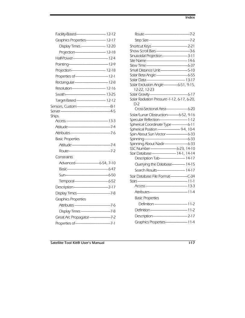
Index
Satellite Tool Kit® User’s Manual I-17
Facility-Based------------------------------------ 12-12
Graphics Properties------------------------ 12-17
Display Times ------------------------------ 12-20
Projection------------------------------------- 12-18
Half-Power-------------------------------------------12-4
Pointing------------------------------------------------12-9
Projection------------------------------------------ 12-18
Properties of----------------------------------------12-1
Rectangular-----------------------------------------12-8
Resolution----------------------------------------- 12-16
Swath------------------------------------------------- 13-25
Target-Based------------------------------------ 12-12
Sensors, Custom-----------------------------------------B-1Server-------------------------------------------------------------4-5Ships
Access ---------------------------------------------------13-3
Attitude----------------------------------------------------7-4
Attributes-------------------------------------------------7-6
Basic Properties
Attitude -----------------------------------------------7-4
Route---------------------------------------------------7-2
Constraints
Advanced-----------------------------6-54, 7-10
Basic--------------------------------------------------6-47
Sun----------------------------------------------------6-50
Temporal-----------------------------------------6-52
Description------------------------------------------2-17
Display Times-----------------------------------------7-8
Graphics Properties
Attributes --------------------------------------------7-6
Display Times ------------------------------------7-8
Great Arc Propagator--------------------------7-2
Properties of-------------------------------------------7-1
Route -------------------------------------------------------7-2
Step Size--------------------------------------------------7-2
Shortcut Keys--------------------------------------------2-21Show Scroll Bars -----------------------------------------3-6Sinusoidal Projection ------------------------------3-11Site Name--------------------------------------------------14-6Slew Time--------------------------------------------------6-37Small Distance Unit---------------------------------5-10Solar Beta Angle --------------------------------------6-55Solar Data----------------------------------------------- 13-17Solar Exclusion Angle-----------------6-51, 9-15, 12-22, 12-23Solar Gravity----------------------------------------------6-17Solar Radiation Pressure -1-12, 6-17, 6-20, D-2
Cross-Sectional Area--------------------------6-20
Solar/Lunar Obstruction-------------6-52, 9-16Specular Reflection----------------------------------1-12Spherical Coordinate Type -------------------6-11Spherical Position --------------------------- 9-4, 10-4Spin About Sun Vector--------------------------6-33Spinning-----------------------------------------------------6-33Spinning About Nadir----------------------------6-33SSC Number-------------------------------6-23, 14-10Star Database -----------------------------14-1, 14-14
Description Tab------------------------------- 14-17
Querying the Database---------------- 14-15
Search Results---------------------------------- 14-17
Star Database File Format---------------------C-34Stars-------------------------------------------------------------11-1
Access ---------------------------------------------------13-3
Attributes----------------------------------------------11-4
Basic Properties
Definition ----------------------------------------11-2
Definition---------------------------------------------11-2
Description------------------------------------------2-17
Graphics Properties---------------------------11-4
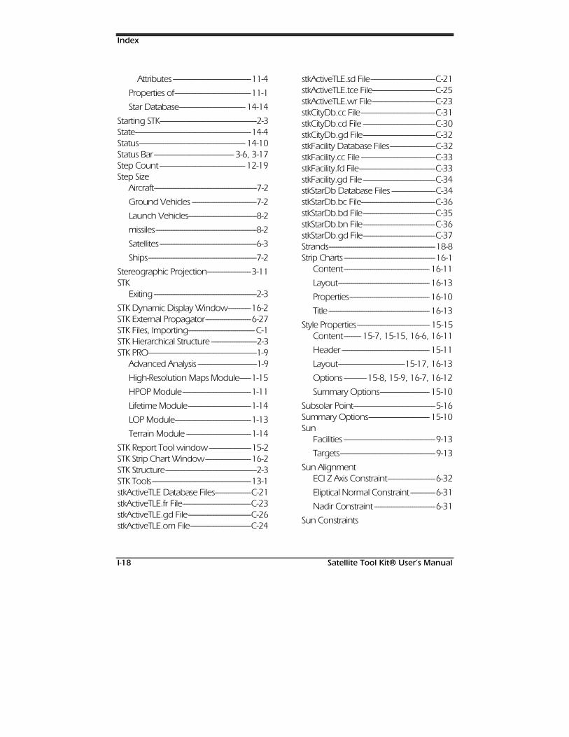
Index
I-18 Satellite Tool Kit® User’s Manual
Attributes -----------------------------------------11-4
Properties of----------------------------------------11-1
Star Database----------------------------------- 14-14
Starting STK---------------------------------------------------2-3State-------------------------------------------------------------14-4Status-------------------------------------------------------- 14-10Status Bar------------------------------------------ 3-6, 3-17Step Count --------------------------------------------- 12-19Step Size
Aircraft------------------------------------------------------7-2
Ground Vehicles ----------------------------------7-2
Launch Vehicles------------------------------------8-2
missiles-----------------------------------------------------8-2
Satellites---------------------------------------------------6-3
Ships---------------------------------------------------------7-2
Stereographic Projection-----------------------3-11STK
Exiting ------------------------------------------------------2-3
STK Dynamic Display Window------------16-2STK External Propagator------------------------6-27STK Files, Importing-----------------------------------C-1STK Hierarchical Structure ------------------------2-3STK PRO---------------------------------------------------------1-9
Advanced Analysis -------------------------------1-9
High-Resolution Maps Module------1-15
HPOP Module------------------------------------1-11
Lifetime Module---------------------------------1-14
LOP Module----------------------------------------1-13
Terrain Module ----------------------------------1-14
STK Report Tool window----------------------15-2STK Strip Chart Window------------------------16-2STK Structure------------------------------------------------2-3STK Tools----------------------------------------------------13-1stkActiveTLE Database Files-------------------C-21stkActiveTLE.fr File------------------------------------C-23stkActiveTLE.gd File---------------------------------C-26stkActiveTLE.om File--------------------------------C-24
stkActiveTLE.sd File----------------------------------C-21stkActiveTLE.tce File---------------------------------C-25stkActiveTLE.wr File---------------------------------C-23stkCityDb.cc File---------------------------------------C-31stkCityDb.cd File --------------------------------------C-30stkCityDb.gd File--------------------------------------C-32stkFacility Database Files------------------------C-32stkFacility.cc File ---------------------------------------C-33stkFacility.fd File----------------------------------------C-33stkFacility.gd File --------------------------------------C-34stkStarDb Database Files -----------------------C-34stkStarDb.bc File---------------------------------------C-36stkStarDb.bd File--------------------------------------C-35stkStarDb.bn File--------------------------------------C-36stkStarDb.gd File--------------------------------------C-37Strands--------------------------------------------------------18-8Strip Charts ------------------------------------------------16-1
Content--------------------------------------------- 16-11
Layout------------------------------------------------ 16-13
Properties------------------------------------------ 16-10
Title ----------------------------------------------------- 16-13
Style Properties-------------------------------------- 15-15Content--------- 15-7, 15-15, 16-6, 16-11
Header ---------------------------------------------- 15-11
Layout-----------------------------------15-17, 16-13
Options ------------15-8, 15-9, 16-7, 16-12
Summary Options-------------------------- 15-10
Subsolar Point-------------------------------------------5-16Summary Options-------------------------------- 15-10Sun
Facilities ------------------------------------------------9-13
Targets--------------------------------------------------9-13
Sun AlignmentECI Z Axis Constraint-------------------------6-32
Eliptical Normal Constraint -------------6-31
Nadir Constraint --------------------------------6-31
Sun Constraints
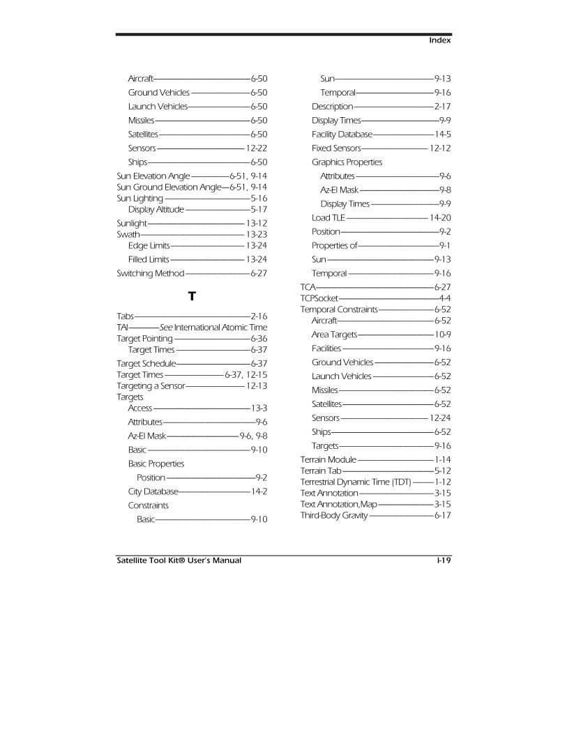
Index
Satellite Tool Kit® User’s Manual I-19
Aircraft---------------------------------------------------6-50
Ground Vehicles -------------------------------6-50
Launch Vehicles---------------------------------6-50
Missiles--------------------------------------------------6-50
Satellites------------------------------------------------6-50
Sensors ---------------------------------------------- 12-22
Ships------------------------------------------------------6-50
Sun Elevation Angle --------------------6-51, 9-14Sun Ground Elevation Angle----6-51, 9-14Sun Lighting ---------------------------------------------5-16
Display Altitude ----------------------------------5-17
Sunlight--------------------------------------------------- 13-12Swath------------------------------------------------------- 13-23
Edge Limits--------------------------------------- 13-24
Filled Limits --------------------------------------- 13-24
Switching Method----------------------------------6-27
TTabs-------------------------------------------------------------2-16TAI----------------See International Atomic TimeTarget Pointing ----------------------------------------6-36
Target Times ---------------------------------------6-37
Target Schedule---------------------------------------6-37Target Times -------------------------------6-37, 12-15Targeting a Sensor------------------------------- 12-13Targets
Access ---------------------------------------------------13-3
Attributes-------------------------------------------------9-6
Az-El Mask--------------------------------------9-6, 9-8
Basic ------------------------------------------------------9-10
Basic Properties
Position -----------------------------------------------9-2
City Database--------------------------------------14-2
Constraints
Basic--------------------------------------------------9-10
Sun----------------------------------------------------9-13
Temporal-----------------------------------------9-16
Description------------------------------------------2-17
Display Times-----------------------------------------9-9
Facility Database--------------------------------14-5
Fixed Sensors----------------------------------- 12-12
Graphics Properties
Attributes --------------------------------------------9-6
Az-El Mask ------------------------------------------9-8
Display Times ------------------------------------9-9
Load TLE ------------------------------------------- 14-20
Position----------------------------------------------------9-2
Properties of-------------------------------------------9-1
Sun --------------------------------------------------------9-13
Temporal ---------------------------------------------9-16
TCA--------------------------------------------------------------6-27TCPSocket-----------------------------------------------------4-4Temporal Constraints-----------------------------6-52
Aircraft---------------------------------------------------6-52
Area Targets----------------------------------------10-9
Facilities ------------------------------------------------9-16
Ground Vehicles -------------------------------6-52
Launch Vehicles --------------------------------6-52
Missiles--------------------------------------------------6-52
Satellites------------------------------------------------6-52
Sensors ---------------------------------------------- 12-24
Ships------------------------------------------------------6-52
Targets--------------------------------------------------9-16
Terrain Module ----------------------------------------1-14Terrain Tab ------------------------------------------------5-12Terrestrial Dynamic Time (TDT) -----------1-12Text Annotation---------------------------------------3-15Text Annotation,Map-----------------------------3-15Third-Body Gravity ----------------------------------6-17
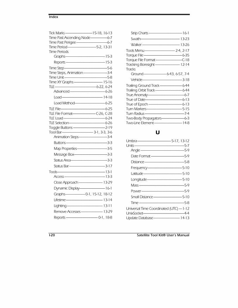
Index
I-20 Satellite Tool Kit® User’s Manual
Tick Marks ----------------------------------15-18, 16-13Time Past Ascending Node---------------------6-7Time Past Perigee ---------------------------------------6-7Time Period------------------------------------5-2, 13-31Time Periods
Graphs--------------------------------------------------15-3
Reports -------------------------------------------------15-3
Time Step------------------------------------------------------5-6Time Steps, Animation------------------------------3-4Time Unit ------------------------------------------------------5-8Time XY Graphs------------------------------------ 15-16TLE----------------------------------------------------6-22, 6-24
Advanced--------------------------------------------6-26
Load--------------------------------------------------- 14-18
Load Method--------------------------------------6-25
TLE File--------------------------------------------------------6-25TLE File Format----------------------------- C-26, C-28TLE Load ----------------------------------------------------6-24TLE Selection---------------------------------------------6-26Toggle Buttons ----------------------------------------2-19Tool Bar--------------------------------------- 3-1, 3-3, 3-6
Animation Steps------------------------------------3-4
Buttons----------------------------------------------------3-3
Map Properties--------------------------------------3-5
Message Box------------------------------------------3-3
Status Area----------------------------------------------3-3
Status Bar---------------------------------------------3-17
Tools------------------------------------------------------------13-1Access ---------------------------------------------------13-3
Close Approach------------------------------ 13-29
Dynamic Display--------------------------------16-1
Graphs-------------------------0-1, 15-12, 18-12
Lifetime---------------------------------------------- 13-14
Lighting--------------------------------------------- 13-11
Remove Accesses --------------------------- 13-29
Reports ---------------------------------------- 0-1, 18-8
Strip Charts ------------------------------------------16-1
Swath------------------------------------------------- 13-23
Walker ----------------------------------------------- 13-26
Tools Menu-------------------------------------- 2-4, 2-17Torque File ------------------------------------------------6-35Torque File Format ---------------------------------C-18Tracking Boresight ------------------------------- 12-14Tracks
Ground---------------------------- 6-43, 6-57, 7-4
Vehicle--------------------------------------------------3-18
Trailing Ground Track----------------------------6-44Trailing Orbit Track----------------------------------6-44True Anomaly----------------------------------------------6-7True of Date----------------------------------------------6-13True of Epoch ------------------------------------------6-13Turn Markers---------------------------------------------5-15Turn Radius--------------------------------------------------7-4Two-Body Propagators-----------------------------6-3Two-Line Element-----------------------------------14-8
UUmbra------------------------------------------5-17, 13-12Units---------------------------------------------------------------5-7
Angle -------------------------------------------------------5-9
Date Format ------------------------------------------5-9
Distance --------------------------------------------------5-8
Frequency-------------------------------------------5-10
Latitude ------------------------------------------------5-10
Longitude--------------------------------------------5-10
Mass ---------------------------------------------------------5-9
Power------------------------------------------------------5-9
Small Distance------------------------------------5-10
Time ---------------------------------------------------------5-8
Universal Time Coordinated (UTC) ----1-12UnixSocket----------------------------------------------------4-4Update Database--------------------------------- 14-13
Index
Satellite Tool Kit® User’s Manual I-21
User Manuals Online -----------------------------17-9Using STK Tools----------------------------------------13-1UTC Gregorian--------------------------------------------5-8UTC Julian ----------------------------------------------------5-8
VVehicle
Attributes-------------------------------------------------7-6
Graphic Properties
Attributes --------------------------------------------7-6
Vehicle Tracks-------------------------------------------3-18Vehicles
Nonorbiting----------------------------------7-1, 8-1
Verbose---------------------------------------------------------4-4Visible Sides-----------------------------------------------6-43Visual Magnitude--------------------------------- 14-16
WWalker Constellation---------------------------- 13-26Waypoints ----------------------------------------------------7-3Windows Menu ----------------------------- 2-4, 2-17
XX Real-Time---------------------------------------------------5-6XY Graphs----------------------------------------------- 15-16
YYaw -------------------------------------------------------------6-34Yaw to Nadir---------------------------------------------6-32YPR Angles-------------------------------------------------6-34
ZZoom In ---------------------------------------15-13, 16-9Zoom Out -----------------------------------15-13, 16-9

Satellite Tool Kit® User’s Manual I-22
127(6

We’d love to hear from you…
At AGI, we work hard to provide quality products and services that meet yourneeds and expectations. Your comments are an important part of our success. Ifyou have any suggestions, please contact us via the World Wide web atwww.stk.com or e-mail us at [email protected] . For our reference, please include thefollowing information along with your response.
Product: Version:
Platform: o UNIX o PC o VAX/VMS Type:
Manual Title: ID #:
Overall Rating of Manual: o Very Good o Good o Satisfactory o Fair oPoor
Comments/Suggestions:
Name:
Title
Company
Address:
We appreciate your suggestions and will consider each responsecarefully. Thank you.
Analytical Graphics, Inc.
660 American AvenueKing of Prussia, PA 19406
(610) 337-3055 /(800) 220-4785Fax: (610) 337-3058/ E-Mail: [email protected]