Embed Size (px)
Citation preview

User’s Manual
Model 121Programmable DC
Current Source
Methods and apparatus disclosed and described herein have been developed solely on company funds of Lake Shore Cryotronics, Inc. No government or other contractual support or relationship whatsoever has existed which in any way affects or mitigates proprietary rights of Lake Shore Cryotronics, Inc. in these developments. Methods and apparatus dis-closed herein may be subject to U.S. Patents existing or applied for. Lake Shore Cryotronics, Inc. reserves the right to add, improve, modify, or withdraw functions, design modifica-tions, or products at any time without notice. Lake Shore shall not be liable for errors con-tained herein or for incidental or consequential damages in connection with furnishing, performance, or use of this material.
Rev. 1.4 P/N 119-061 13 February 2017
Lake Shore Cryotronics, Inc.575 McCorkle Blvd.
Westerville, Ohio 43082-8888 USA
[email protected]@lakeshore.com
www.lakeshore.com
Fax: (614) 891-1392 B Telephone: (614) 891-2243

LIMITED WARRANTY STATEMENTWARRANTY PERIOD: THREE (3) YEARS1.Lake Shore warrants that products manufactured by Lake Shore (the "Product") will be free from defects in materials and workmanship for three years from the date of Pur-chaser's physical receipt of the Product (the "Warranty Period"). If Lake Shore receives notice of any such defects during the Warranty Period and the defective Product is shipped freight prepaid back to Lake Shore, Lake Shore will, at its option, either repair or replace the Product (if it is so defective) without charge for parts, service labor or associated customary return shipping cost to the Purchaser. Replacement for the Product may be by either new or equivalent in performance to new. Replacement or repaired parts, or a replaced Product, will be warranted for only the unexpired portion of the original warranty or 90 days (whichever is greater)..
2.Lake Shore warrants the Product only if the Product has been sold by an authorized Lake Shore employee, sales representative, dealer or an authorized Lake Shore original equip-ment manufacturer (OEM).
3.The Product may contain remanufactured parts equivalent to new in performance or may have been subject to incidental use when it is originally sold to the Purchaser.
4.The Warranty Period begins on the date the Product ships from Lake Shore’s plant.
5.This limited warranty does not apply to defects in the Product resulting from (a) improper or inadequate installation (unless OT&V services are performed by Lake Shore), mainte-nance, repair or calibration, (b) fuses, software, power surges, lightning and non-recharge-able batteries, (c) software, interfacing, parts or other supplies not furnished by Lake Shore, (d) unauthorized modification or misuse, (e) operation outside of the published specifica-tions, (f ) improper site preparation or site maintenance (g) natural disasters such as flood, fire, wind, or earthquake, or (h) damage during shipment other than original shipment to you if shipped through a Lake Shore carrier.
6.This limited warranty does not cover: (a) regularly scheduled or ordinary and expected recalibrations of the Product; (b) accessories to the Product (such as probe tips and cables, holders, wire, grease, varnish, feed throughs, etc.); (c) consumables used in conjunction with the Product (such as probe tips and cables, probe holders, sample tails, rods and hold-ers, ceramic putty for mounting samples, Hall sample cards, Hall sample enclosures, etc.); or, (d) non-Lake Shore branded Products that are integrated with the Product.
7. To the extent allowed by applicable law,, this limited warranty is the only warranty applicable to the Product and replaces all other warranties or conditions, express or implied, including, but not limited to, the implied warranties or conditions of merchantabi-lity and fitness for a particular purpose. Specifically, except as provided herein,

LakeShore undertakes no responsibility that the products will be fit for any particular pur-pose for which you may be buying the Products. Any implied warranty is limited in duration to the warranty period. No oral or written information, or advice given by the Company, its Agents or Employees, shall create a warranty or in any way increase the scope of this lim-ited warranty. Some countries, states or provinces do not allow limitations on an implied warranty, so the above limitation or exclusion might not apply to you. This warranty gives you specific legal rights and you might also have other rights that vary from country to country, state to state or province to province.
8.Further, with regard to the United Nations Convention for International Sale of Goods (CISC,) if CISG is found to apply in relation to this agreement, which is specifically dis-claimed by Lake Shore, then this limited warranty excludes warranties that: (a) the Product is fit for the purpose for which goods of the same description would ordinarily be used, (b) the Product is fit for any particular purpose expressly or impliedly made known to Lake Shore at the time of the conclusion of the contract. (c) the Product is contained or packaged in a manner usual for such goods or in a manner adequate to preserve and protect such goods where it is shipped by someone other than a carrier hired by Lake Shore.
9. Lake Shore disclaims any warranties of technological value or of non-infringement with respect to the Product and Lake Shore shall have no duty to defend, indemnify, or hold harmless you from and against any or all damages or costs incurred by you arising from the infringement of patents or trademarks or violation or copyrights by the Product.
10.THIS WARRANTY IS NOT TRANSFERRABLE. This warranty is not transferrable.
11.Except to the extent prohibited by applicable law, neither Lake Shore nor any of its sub-sidiaries, affiliates or suppliers will be held liable for direct, special, incidental, consequen-tial or other damages (including lost profit, lost data, or downtime costs) arising out of the use, inability to use or result of use of the product, whether based in warranty, contract, tort or other legal theory, regardless whether or not Lake Shore has been advised of the possibility of such damages. Purchaser's use of the Product is entirely at Purchaser's risk. Some countries, states and provinces do not allow the exclusion of liability for incidental or consequential damages, so the above limitation may not apply to you.
12.This limited warranty gives you specific legal rights, and you may also have other rights that vary within or between jurisdictions where the product is purchased and/or used. Some jurisdictions do not allow limitation in certain warranties, and so the above limita-tions or exclusions of some warranties stated above may not apply to you.
13.Except to the extent allowed by applicable law, the terms of this limited warranty state-ment do not exclude, restrict or modify the mandatory statutory rights applicable to the sale of the product to you.
CERTIFICATIONLake Shore certifies that this product has been inspected and tested in accordance with its published specifications and that this product met its published specifications at the time of shipment. The accuracy and calibration of this product at the time of shipment are traceable to the United States National Institute of Standards and Technology (NIST); for-merly known as the National Bureau of Standards (NBS).
FIRMWARE LIMITATIONSLake Shore has worked to ensure that the Model 121 firmware is as free of errors as possi-ble, and that the results you obtain from the instrument are accurate and reliable. How-ever, as with any computer-based software, the possibility of errors exists.
In any important research, as when using any laboratory equipment, results should be carefully examined and rechecked before final conclusions are drawn. Neither Lake Shore nor anyone else involved in the creation or production of this firmware can pay for loss of time, inconvenience, loss of use of the product, or property damage caused by this product or its failure to work, or any other incidental or consequential damages. Use of our product implies that you understand the Lake Shore license agreement and statement of limited warranty.
FIRMWARE LICENSE AGREEMENTThe firmware in this instrument is protected by United States copyright law and interna-tional treaty provisions. To maintain the warranty, the code contained in the firmware must not be modified. Any changes made to the code is at the user's risk. Lake Shore will assume no responsibility for damage or errors incurred as result of any changes made to the firmware.
Under the terms of this agreement you may only use the Model 121 firmware as physically installed in the instrument. Archival copies are strictly forbidden. You may not decompile, disassemble, or reverse engineer the firmware. If you suspect there are problems with the firmware, return the instrument to Lake Shore for repair under the terms of the Limited Warranty specified above. Any unauthorized duplication or use of the Model 121 firmware in whole or in part, in print, or in any other storage and retrieval system is forbidden.
TRADEMARK ACKNOWLEDGMENTMany manufacturers and sellers claim designations used to distinguish their products as trademarks. Where those designations appear in this manual and Lake Shore was aware of a trademark claim, they appear with initial capital letters and the ™ or ® symbol.
Cernox® is a trademarks of Lake Shore Cryotronics, Inc.
Microsoft Windows®, Excel®, Windows XP®, and Windows Vista® are registered trademarks of Microsoft Corporation in the United States and other countries.
Copyright 2013-2017 by Lake Shore Cryotronics, Inc. All rights reserved. No portion of this manual may be reproduced, stored in a retrieval system, or transmitted, in any form or by any means, electronic, mechanical, photocopying, recording, or otherwise, without the express written permission of Lake Shore.

Electromagnetic Compatibility (EMC) for the Model 121 Current SourceElectromagnetic Compatibility (EMC) of electronic equipment is a growing concern world-wide. Emissions of and immunity to electromagnetic interference is now part of the design and manufacture of most electronics. To qualify for the CE Mark, the Model 121 meets or exceeds the requirements of the European EMC Directive 89/336/EEC as a CLASS A prod-uct. A Class A product is allowed to radiate more RF than a Class B product and must include the following warning:
WARNING:This is a Class A product. In a domestic environment, this product may cause radio interference in which case the user may be required to take adequate measures.
The instrument was tested under normal operating conditions with sensor and interface cables attached. If the installation and operating instructions in the User's Manual are fol-lowed, there should be no degradation in EMC performance.
This instrument is not intended for use in close proximity to RF Transmitters such as two-way radios and cell phones. Exposure to RF interference greater than that found in a typical laboratory environment may disturb the sensitive measurement circuitry of the instru-ment.
Pay special attention to instrument cabling. Improperly installed cabling may defeat even the best EMC protection. For the best performance from any precision instrument, follow the grounding and shielding instructions in the User's Manual. In addition, the installer of the Model 121 should consider the following:
D Shield measurement and computer interface cables.
D Leave no unused or unterminated cables attached to the instrument.
D Make cable runs as short and direct as possible. Higher radiated emissions are possible with long cables.
D Do not tightly bundle cables that carry different types of signals.


i
Table of Contents
Chapter 1: Introduction1.1 Overview . . . . . . . . . . . . . . . . . . . . . . . . . . . . . . . . . . . . . . . . . . . . . . . . . . . . . . . . . . . . .11.2 Applications . . . . . . . . . . . . . . . . . . . . . . . . . . . . . . . . . . . . . . . . . . . . . . . . . . . . . . . . . .21.3 Model 121 Specifications . . . . . . . . . . . . . . . . . . . . . . . . . . . . . . . . . . . . . . . . . . . .3
1.3.1 Output . . . . . . . . . . . . . . . . . . . . . . . . . . . . . . . . . . . . . . . . . . . . . . . . . . . . . . . . .31.3.2 User setting . . . . . . . . . . . . . . . . . . . . . . . . . . . . . . . . . . . . . . . . . . . . . . . . . . . .3
1.3.2.1 Programming . . . . . . . . . . . . . . . . . . . . . . . . . . . . . . . . . . . . . . . . . .31.3.2.2 Front panel . . . . . . . . . . . . . . . . . . . . . . . . . . . . . . . . . . . . . . . . . . . .41.3.2.3 Interface . . . . . . . . . . . . . . . . . . . . . . . . . . . . . . . . . . . . . . . . . . . . . . .4
1.3.3 General . . . . . . . . . . . . . . . . . . . . . . . . . . . . . . . . . . . . . . . . . . . . . . . . . . . . . . . .41.4 Safety Summary and Symbols . . . . . . . . . . . . . . . . . . . . . . . . . . . . . . . . . . . . . . . .4
Chapter 2: Installation2.1 General . . . . . . . . . . . . . . . . . . . . . . . . . . . . . . . . . . . . . . . . . . . . . . . . . . . . . . . . . . . . . . .72.2 Inspecting and Unpacking . . . . . . . . . . . . . . . . . . . . . . . . . . . . . . . . . . . . . . . . . . .72.3 Rear Panel Definition . . . . . . . . . . . . . . . . . . . . . . . . . . . . . . . . . . . . . . . . . . . . . . . . .82.4 Power Input Connector . . . . . . . . . . . . . . . . . . . . . . . . . . . . . . . . . . . . . . . . . . . . . .92.5 External Power Supply . . . . . . . . . . . . . . . . . . . . . . . . . . . . . . . . . . . . . . . . . . . . . . .92.6 Cable Clamp . . . . . . . . . . . . . . . . . . . . . . . . . . . . . . . . . . . . . . . . . . . . . . . . . . . . . . . . 102.7 Current Source Output . . . . . . . . . . . . . . . . . . . . . . . . . . . . . . . . . . . . . . . . . . . . . 10
2.7.1 Current Source Output Connector . . . . . . . . . . . . . . . . . . . . . . . . . . . 102.7.2 Sensor Lead Cable . . . . . . . . . . . . . . . . . . . . . . . . . . . . . . . . . . . . . . . . . . . 112.7.3 Grounding and Shielding Sensor Leads . . . . . . . . . . . . . . . . . . . . . . 112.7.4 Sensor Polarity . . . . . . . . . . . . . . . . . . . . . . . . . . . . . . . . . . . . . . . . . . . . . . . 12
2.7.4.1 Resistive Sensors . . . . . . . . . . . . . . . . . . . . . . . . . . . . . . . . . . . . . 122.7.4.2 Diode Sensors . . . . . . . . . . . . . . . . . . . . . . . . . . . . . . . . . . . . . . . . 122.7.4.3 Hall Generators . . . . . . . . . . . . . . . . . . . . . . . . . . . . . . . . . . . . . . 13
2.7.5 Lowering Measurement Noise . . . . . . . . . . . . . . . . . . . . . . . . . . . . . . . 142.8 Rack Mounting . . . . . . . . . . . . . . . . . . . . . . . . . . . . . . . . . . . . . . . . . . . . . . . . . . . . . 14
Chapter 3: Operation3.1 General . . . . . . . . . . . . . . . . . . . . . . . . . . . . . . . . . . . . . . . . . . . . . . . . . . . . . . . . . . . . . 153.2 Instrument Power . . . . . . . . . . . . . . . . . . . . . . . . . . . . . . . . . . . . . . . . . . . . . . . . . 153.3 Front Panel Description . . . . . . . . . . . . . . . . . . . . . . . . . . . . . . . . . . . . . . . . . . . . 16
3.3.1 Keypad Definitions . . . . . . . . . . . . . . . . . . . . . . . . . . . . . . . . . . . . . . . . . . . 163.3.2 Display Annunciators . . . . . . . . . . . . . . . . . . . . . . . . . . . . . . . . . . . . . . . . 16
3.4 Display Brightness . . . . . . . . . . . . . . . . . . . . . . . . . . . . . . . . . . . . . . . . . . . . . . . . . 173.5 Output Current Setup . . . . . . . . . . . . . . . . . . . . . . . . . . . . . . . . . . . . . . . . . . . . . . 17
ii
3.5.1 Enable/Disable . . . . . . . . . . . . . . . . . . . . . . . . . . . . . . . . . . . . . . . . . . . . . . .173.5.2 Range Change . . . . . . . . . . . . . . . . . . . . . . . . . . . . . . . . . . . . . . . . . . . . . . . .173.5.3 Polarity Change . . . . . . . . . . . . . . . . . . . . . . . . . . . . . . . . . . . . . . . . . . . . . .183.5.4 User Current . . . . . . . . . . . . . . . . . . . . . . . . . . . . . . . . . . . . . . . . . . . . . . . . . .193.5.5 Power Up Enable. . . . . . . . . . . . . . . . . . . . . . . . . . . . . . . . . . . . . . . . . . . . . .19
3.6 Power Up State . . . . . . . . . . . . . . . . . . . . . . . . . . . . . . . . . . . . . . . . . . . . . . . . . . . . .193.7 Locking and Unlocking the Keypad . . . . . . . . . . . . . . . . . . . . . . . . . . . . . . . . .20
Chapter 4: Computer Interface Operation4.1 General . . . . . . . . . . . . . . . . . . . . . . . . . . . . . . . . . . . . . . . . . . . . . . . . . . . . . . . . . . . . .214.2 USB Interface . . . . . . . . . . . . . . . . . . . . . . . . . . . . . . . . . . . . . . . . . . . . . . . . . . . . . . .21
4.2.1 Physical Connection . . . . . . . . . . . . . . . . . . . . . . . . . . . . . . . . . . . . . . . . .214.2.2 Hardware Support. . . . . . . . . . . . . . . . . . . . . . . . . . . . . . . . . . . . . . . . . . . 214.2.3 Installing the USB Driver . . . . . . . . . . . . . . . . . . . . . . . . . . . . . . . . . . . . .22
4.2.3.1 Installing the Driver From Windows® Update in Windows Vista®, Windows® 7, and Windows® 8 . . . .22
4.2.3.2 Installing the Driver From Windows® Update in Windows® XP . . . . . . . . . . . . . . . . . . . . . . . . . . . . . . . . . . . . .23
4.2.3.3 Installing the Driver from the Web . . . . . . . . . . . . . . . . . .234.2.3.3.1 Download the driver . . . . . . . . . . . . . . . . . . . . . . . .234.2.3.3.2 Extract the driver . . . . . . . . . . . . . . . . . . . . . . . . . . .244.2.3.3.3 Manually install the driver . . . . . . . . . . . . . . . . .24
4.2.3.4 Installing the USB Driver from the Included CD . . . . .264.2.4 Communication . . . . . . . . . . . . . . . . . . . . . . . . . . . . . . . . . . . . . . . . . . . . . .27
4.2.4.1 Character Format . . . . . . . . . . . . . . . . . . . . . . . . . . . . . . . . . . . .274.2.4.2 Message Strings . . . . . . . . . . . . . . . . . . . . . . . . . . . . . . . . . . . . .27
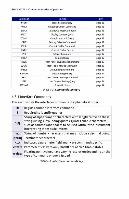
4.2.5 Message Flow Control . . . . . . . . . . . . . . . . . . . . . . . . . . . . . . . . . . . . . . .284.3 Command Summary . . . . . . . . . . . . . . . . . . . . . . . . . . . . . . . . . . . . . . . . . . . . . . .29
4.3.1 Interface Commands . . . . . . . . . . . . . . . . . . . . . . . . . . . . . . . . . . . . . . . .30
Chapter 5: Options and Accessories5.1 General . . . . . . . . . . . . . . . . . . . . . . . . . . . . . . . . . . . . . . . . . . . . . . . . . . . . . . . . . . . . .355.2 Models . . . . . . . . . . . . . . . . . . . . . . . . . . . . . . . . . . . . . . . . . . . . . . . . . . . . . . . . . . . . . .355.3 Accessories . . . . . . . . . . . . . . . . . . . . . . . . . . . . . . . . . . . . . . . . . . . . . . . . . . . . . . . . .35
Chapter 6: Service6.1 General . . . . . . . . . . . . . . . . . . . . . . . . . . . . . . . . . . . . . . . . . . . . . . . . . . . . . . . . . . . . .376.2 USB Troubleshooting . . . . . . . . . . . . . . . . . . . . . . . . . . . . . . . . . . . . . . . . . . . . . . .37
6.2.1 New Installation . . . . . . . . . . . . . . . . . . . . . . . . . . . . . . . . . . . . . . . . . . . . .376.2.2 Existing Installation No Longer Working . . . . . . . . . . . . . . . . . . . . 386.2.3 Intermittent Lockups . . . . . . . . . . . . . . . . . . . . . . . . . . . . . . . . . . . . . . . . 38

iii
6.3 Factory Reset . . . . . . . . . . . . . . . . . . . . . . . . . . . . . . . . . . . . . . . . . . . . . . . . . . . . . . 396.4 Product Information . . . . . . . . . . . . . . . . . . . . . . . . . . . . . . . . . . . . . . . . . . . . . . . 396.5 Error Messages . . . . . . . . . . . . . . . . . . . . . . . . . . . . . . . . . . . . . . . . . . . . . . . . . . . . . 396.6 Calibration Procedure . . . . . . . . . . . . . . . . . . . . . . . . . . . . . . . . . . . . . . . . . . . . . 396.7 Rear Panel Connector Definition . . . . . . . . . . . . . . . . . . . . . . . . . . . . . . . . . . 406.8 Firmware Updates . . . . . . . . . . . . . . . . . . . . . . . . . . . . . . . . . . . . . . . . . . . . . . . . . 41
6.8.1 Updating the Firmware . . . . . . . . . . . . . . . . . . . . . . . . . . . . . . . . . . . . . . 416.8.2 Record of Updates Made to the Firmware . . . . . . . . . . . . . . . . . . . 41
6.9 Technical Inquiries . . . . . . . . . . . . . . . . . . . . . . . . . . . . . . . . . . . . . . . . . . . . . . . . . 426.9.1 Contacting Lake Shore . . . . . . . . . . . . . . . . . . . . . . . . . . . . . . . . . . . . . . . 426.9.2 Return of Equipment . . . . . . . . . . . . . . . . . . . . . . . . . . . . . . . . . . . . . . . . 426.9.3 RMA Valid Period . . . . . . . . . . . . . . . . . . . . . . . . . . . . . . . . . . . . . . . . . . . . 436.9.4 Shipping Charges . . . . . . . . . . . . . . . . . . . . . . . . . . . . . . . . . . . . . . . . . . . . 436.9.5 Restocking Fee . . . . . . . . . . . . . . . . . . . . . . . . . . . . . . . . . . . . . . . . . . . . . . . 43
Appendix A: Handling Liquid Helium and NitrogenA.1 General . . . . . . . . . . . . . . . . . . . . . . . . . . . . . . . . . . . . . . . . . . . . . . . . . . . . . . . . . . . . . 45A.2 Properties . . . . . . . . . . . . . . . . . . . . . . . . . . . . . . . . . . . . . . . . . . . . . . . . . . . . . . . . . . 45A.3 Handling Cryogenic Storage Dewars . . . . . . . . . . . . . . . . . . . . . . . . . . . . . . 46A.4 Liquid Helium and Nitrogen Safety Precautions . . . . . . . . . . . . . . . . . . . 46A.5 Recommended First Aid . . . . . . . . . . . . . . . . . . . . . . . . . . . . . . . . . . . . . . . . . . . . 48
Appendix B: Regulatory Declarations B.1 General . . . . . . . . . . . . . . . . . . . . . . . . . . . . . . . . . . . . . . . . . . . . . . . . . . . . . . . . . . . . . 49
B.1.1 CE Declaration for Model 121 . . . . . . . . . . . . . . . . . . . . . . . . . . . . . . . 50B.1.2 CE Declaration for the Power Supply,
Part Number 109-132 . . . . . . . . . . . . . . . . . . . . . . . . . . . . . . . . . . . . . . . . 51

iv

1
Chapter 1: Introduction
1.1 OverviewThe Model 121 programmable DC current source is a precision instru-ment suitable for bench-top use or panel-mounted operation in labs, test facilities, and manufacturing environments. It provides a low noise, highly-stable source of current up to 100 mA, with convenient manual selection through 13 pre-set output levels, each representing a ten-fold change in power when attached to a resistive load. A “user” setting allows the current output to be defined anywhere within the operating range of the unit, from 100 nA to 100 mA.
Programmable operation is also possible via the instrument’s USB com-puter interface, through which the Model 121 can be commanded to output any desired current at any time. Thus, application-specific test currents can be driven from an external PC.
The instrument operates at 5 VDC, and power is supplied by the external AC wall-mount supply provided with the standard Model 121. The sup-ply will automatically conform to any AC line voltage ranging from 100 VAC to 240 VAC, 50 or 60 Hz.
D 7 decades of output current, selectable in 13 steps D Programmable current output, 100 nA to 100 mAD Low-noise outputD Large 3 digit LED displayD Simple user interface D Current reversal featureD USB interface enables integration with automated test systemsD DIN panel-mountable package D Detachable output terminal blockD CE mark certification

2 CHAPTER 1: Introduction
1.2 ApplicationsThe Model 121 current source is ideally suited for testing, measuring, and operating resistive and semiconductor devices, such as:
D Lake Shore Cernox™ temperature sensorsD Other resistance temperature detectors (RTDs) such as platinum
sensors D Diode temperature sensors, including Lake Shore DT-670’sD LED devicesD Hall sensors used for magnetic field measurement
An accurate, stable source of current is key to ensuring consistent opera-tion of these devices, where the voltage drop across the device can be dependent upon temperature, magnetic field, and other parameters. The instrument's wide output range is of great value when used with RTD-type sensors whose resistance can vary with temperature by as much as 6 orders of magnitude. The current reversal feature enables compensation for thermal EMF, important for accurately measuring resistors at very low excitation levels.
Example applications include:
D Basic device QC ("good/bad" verification)D LED brightness testing (constant device current)D Temperature sensor calibration (determine resistance at fixed cali-
bration points)D Temperature measurement (using a voltmeter readout)D Magnetic sensor calibration and measurementD Semiconductor device measurements (IV curves for diodes, transis-
tors, etc.)D Circuit prototyping (fixed current source)D Small scale electro-chemical applications
Whether operating over a wide range of environmental conditions, establishing precise sensor calibrations or simply testing devices for conformance, the Model 121 provides a convenient and reliable alterna-tive to simple voltage-based circuits, and a very affordable alternative to more expensive multi-function current sources. It can be readily inte-grated into automated test systems using its built-in USB computer interface and offers a highly readable, simple-to-use operator display.

3
1.3 Model 121 Specifications
1.3.1 OutputType: Bipolar, DC current sourceCurrent ranges: 13 fixed ranges of 100 nA, 300 nA, 1 µA, 3 µA, 10 µA, 30 µA, 100 µA, 300 µA, 1 mA, 3 mA, 10 mA, 30 mA, 100 mA, and a user-pro-grammable rangeAccuracy: 0.05% on 10 µA range, 0.5% on 100 nA and 300 nA ranges, 0.1% on all other rangesCompliance voltage: ±11 V up to 30 mA, ±10 V up to 100 mA AC current ripple: < 0.1% on 100 nA and 300 nA ranges; < 0.01% on all other ranges in a properly shielded systemCurrent ripple frequency: Dominated by line frequency and its harmonicsTemperature coefficient: 0.03% of range/°C for the 100 nA range, 0.01% of range/°C for all other rangesLine regulation: < 0.01% change in output for 5% change in the DC input voltageLoad regulation: < 0.01% change in output current over the full-scale rangeStability (24 h): 0.05% on 100 nA range, 0.01% per day on all other fixed rangesSettling time: <300 ms for full-scale change in current; <100 ms for 10% change in currentConnector: Detachable terminal blockMaximum load: 300 k
1.3.2 User setting
1.3.2.1 Programming
Operation: Output current settable via computer interfaceResolution: 3 significant digitsAccuracy: 0.5% for currents <300 nA, 0.25% for all other currentsMaximum current: 100 mAMinimum current: 100 nA

4 CHAPTER 1: Introduction
1.3.2.2 Front panel
Display: 6-digit LED displayDisplay units: mA, µA, and nADisplay update rate: 2 rdg/sDisplay anunciators: mA, µA, nA, and complianceKeypad: 4 full-travel keysKeypad functions: Range Up, Range Down, Current Polarity, Enable/Disable
1.3.2.3 Interface
USB Function: Emulates an RS-232 serial portBaud rate: 57,600Connector: B-type USB connectorReading rate: Up to 10 rdg/s Software support: LabVIEW™ driver (consult Lake Shore for availability)
1.3.3 GeneralAmbient temperature: 15 °C to 35 °C at rated accuracy; 5 °C to 40 °C at reduced accuracyPower requirement: +5 VDC ±5% at 250 mA, barrel plug 5.5 mm OD × 2.1 mm ID × 9.9 mm L Size: 96 mm W × 48 mm H × 166 mm D (3.8 in × 1.9 in × 6.5 in)Mounting: Panel mount into 91 mm W × 44 mm H (3.6 in × 1.7 in) cutoutWeight: 0.45 kg (1 lb) Approval: CE Mark
1.4 Safety Summary and SymbolsObserve these general safety precautions during all phases of instru-ment operation, service, and repair. Failure to comply with these precau-tions or with specific warnings elsewhere in this manual violates safety standards of design, manufacture, and intended instrument use. Lake Shore Cryotronics, Inc. assumes no liability for Customer failure to com-ply with these requirements.
The Model 121 protects the operator and surrounding area from electric shock or burn, mechanical hazards, excessive temperature, and spread of fire from the instrument. Environmental conditions outside of the conditions below may pose a hazard to the operator and surrounding area.

5
D Indoor useD Altitude to 2000 mD Temperature for safe operation: 5 °C to 40 °CD Maximum relative humidity: 80% for temperature up to 31 °C
decreasing linearly to 50% at 40 °CD Power supply voltage fluctuations not to exceed ±10% of the nomi-
nal voltage*D Overvoltage category IID Pollution degree 2
*The power supply included with the Model 121 meets or exceeds the European Union Standard, EN-60950.
Do Not Operate in an Explosive AtmosphereDo not operate the instrument in the presence of flammable gases or fumes. Operation of any electrical instrument in such an environment constitutes a definite safety hazard.
Keep Away from Live CircuitsOperating personnel must not remove instrument covers. Refer compo-nent replacement and internal adjustments to qualified maintenance personnel. Do not replace components with power cable connected. To avoid injuries, always disconnect power and discharge circuits before touching them.
Do Not Substitute Parts or Modify InstrumentDo not install substitute parts or perform any unauthorized modification to the instrument. Return the instrument to an authorized Lake Shore Cryotronics, Inc. representative for service and repair to ensure that safety features are maintained.
CleaningDo not submerge instrument. Clean only the exterior of the instrument with a damp cloth and mild detergent.
6 CHAPTER 1: Introduction
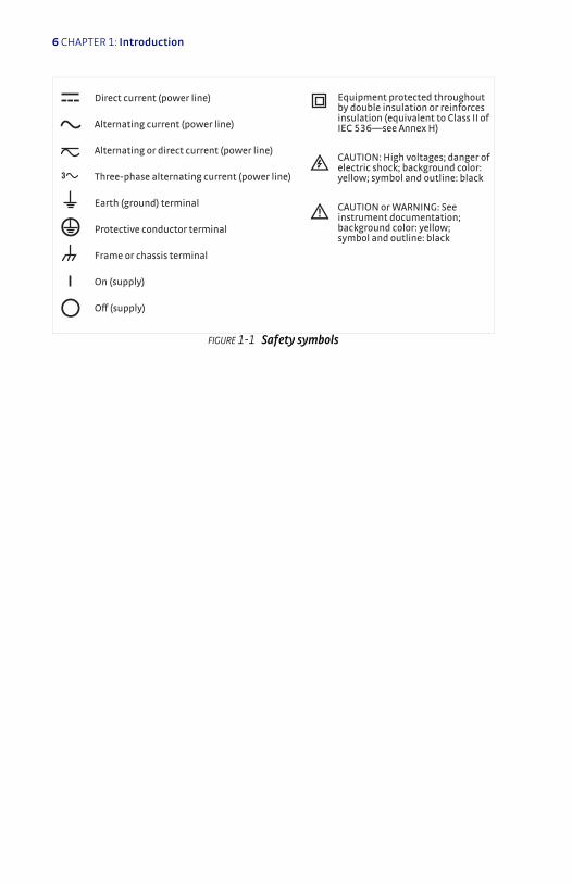
FIGURE 1-1 Safety symbols
!
Direct current (power line) Equipment protected throughout by double insulation or reinforces insulation (equivalent to Class II of IEC 536—see Annex H)
CAUTION: High voltages; danger of electric shock; background color: yellow; symbol and outline: black
CAUTION or WARNING: See instrument documentation; background color: yellow; symbol and outline: black
Off (supply)
On (supply)
Frame or chassis terminal
Protective conductor terminal
Earth (ground) terminal
3 Three-phase alternating current (power line)
Alternating or direct current (power line)
Alternating current (power line)

7
Chapter 2: Installation
2.1 GeneralThis chapter provides general installation instructions for the Model 121 current source. Please read this entire chapter before installing the instrument and powering it on to ensure the best possible performance and maintain operator safety. For instrument operating instructions refer to Chapter 3. For computer interface installation and operation refer to Chapter 4.
2.2 Inspecting and UnpackingInspect shipping containers for external damage before opening them. Photograph any container that has significant damage before opening it. Inspect all items for both visible and hidden damage that may have occurred during shipment. If there is visible damage to the contents of the container, contact the shipping company and Lake Shore immedi-ately, preferably within five days of receipt of goods, for instructions on how to file a proper insurance claim. Lake Shore products are insured against damage during shipment, but a timely claim must be filed before Lake Shore will take further action. Procedures vary slightly with ship-ping companies. Keep all damaged shipping materials and contents until instructed to either return or discard them.
Open the shipping container and keep the container and shipping mate-rials until all contents have been accounted for. Check off each item on the packing list as it is unpacked. Instruments themselves may be shipped as several parts. The items included with the Model 121 are listed below. Contact Lake Shore immediately if there is a shortage of parts or accessories. Lake Shore is not responsible for any missing items if not notified within 60 days of shipment.
If the instrument must be returned for recalibration, replacement or repair, a Return Authorization (RMA) number must be obtained from a factory representative before it is returned. Refer to section 6.9.3 for the Lake Shore RMA procedure.
Items Included with Model 121 current source:D 1 Model 121 instrumentD 1 Model 121 user’s manual
8 CHAPTER 2: Installation
D 1 terminal block mating connector, 2-pin terminal block, for current source output (G-106-735)
D 4 adhesive square rubber feetD 1 cable clamp, for power supply cordD 1 universal input power supply (interchangeable plug style)*
(109-132)
* Not included with the 121N option
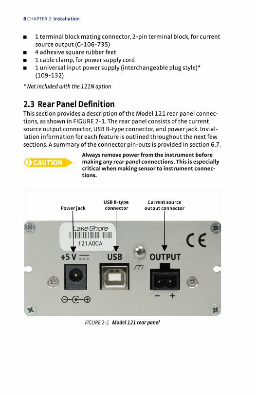
2.3 Rear Panel DefinitionThis section provides a description of the Model 121 rear panel connec-tions, as shown in FIGURE 2-1. The rear panel consists of the current source output connector, USB B-type connector, and power jack. Instal-lation information for each feature is outlined throughout the next few sections. A summary of the connector pin-outs is provided in section 6.7.
Always remove power from the instrument before making any rear panel connections. This is especially critical when making sensor to instrument connec-tions.
FIGURE 2-1 Model 121 rear panel
9
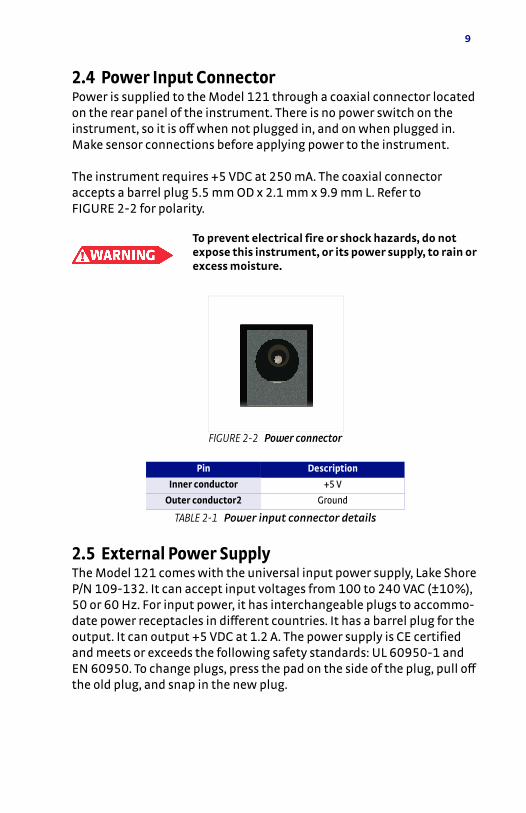
2.4 Power Input ConnectorPower is supplied to the Model 121 through a coaxial connector located on the rear panel of the instrument. There is no power switch on the instrument, so it is off when not plugged in, and on when plugged in. Make sensor connections before applying power to the instrument.
The instrument requires +5 VDC at 250 mA. The coaxial connector accepts a barrel plug 5.5 mm OD x 2.1 mm x 9.9 mm L. Refer to FIGURE 2-2 for polarity.
To prevent electrical fire or shock hazards, do not expose this instrument, or its power supply, to rain or excess moisture.
2.5 External Power SupplyThe Model 121 comes with the universal input power supply, Lake Shore P/N 109-132. It can accept input voltages from 100 to 240 VAC (±10%), 50 or 60 Hz. For input power, it has interchangeable plugs to accommo-date power receptacles in different countries. It has a barrel plug for the output. It can output +5 VDC at 1.2 A. The power supply is CE certified and meets or exceeds the following safety standards: UL 60950-1 and EN 60950. To change plugs, press the pad on the side of the plug, pull off the old plug, and snap in the new plug.
FIGURE 2-2 Power connector
Pin Description
Inner conductor +5 V
Outer conductor2 Ground
TABLE 2-1 Power input connector details
10 CHAPTER 2: Installation
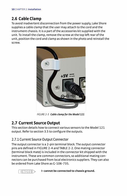
2.6 Cable ClampTo avoid inadvertent disconnection from the power supply, Lake Shore supplies a cable clamp that the user may attach to the cord and the instrument chassis. It is a part of the accessories kit supplied with the unit. To install the clamp, remove the screw at the top left rear of the unit, position the cord and clamp as shown in the photo and reinstall the screw.
2.7 Current Source OutputThis section details how to connect various sensors to the Model 121 output. Refer to section 3.5 to configure the outputs.
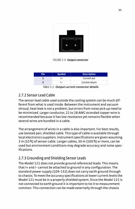
2.7.1 Current Source Output ConnectorThe output connector is a 2-pin terminal block. The output connector pins are defined in FIGURE 2-4 and TABLE 2-2. One mating connector (terminal block mate) is included in the connector kit shipped with the instrument. These are common connectors, so additional mating con-nectors can be purchased from local electronics suppliers. They can also be ordered from Lake Shore as G-106-735.
I- cannot be connected to chassis ground.
FIGURE 2-3 Cable clamp for the Model 121
+5V
11
2.7.2 Sensor Lead CableThe sensor lead cable used outside the cooling system can be much dif-ferent from what is used inside. Between the instrument and vacuum shroud, heat leak is not a problem, but errors from noise pick up need to be minimized. Larger conductor, 22 to 28 AWG stranded copper wire is recommended because it has low resistance yet remains flexible when several wires are bundled in a cable.
The arrangement of wires in a cable is also important. For best results, use twisted pair, shielded cable. This type of cable is available through local electronics suppliers. Instrument specifications are given assuming 3 m (10 ft) of sensor cable. Longer cables, 30 m (100 ft) or more, can be used but environment conditions may degrade accuracy and noise spec-ifications.
2.7.3 Grounding and Shielding Sensor LeadsThe Model 121 does not provide ground referenced leads. This means that I+ and I- cannot be attached to ground in any configuration. The standard power supply (109-132) does not carry earth ground through to chassis. To meet the accuracy specifications at lower current levels the Model 121 must be in a properly shielded system. Since the Model 121 is not connected to earth ground it is important to tie it to measurement common. This connection can be made externally through the chassis
FIGURE 2-4 Output connector
Pin Symbol Description
1 I+ Current out
2 I– Current return
TABLE 2-2 Output current connector details
12 CHAPTER 2: Installation
ground connection on the rear panel. It is also advised to use sensor leads that are shielded and floating. The shield should be tied to mea-surement common. When making any such connections, it is important to avoid ground loops by connecting measurement commons at one point.
2.7.4 Sensor PolarityLake Shore sensors are shipped with instructions that indicate which sensor leads are which. It is important to follow these instructions for plus and minus leads (polarity) as well as voltage and current when applicable.
2.7.4.1 Resistive Sensors
There are two styles of resistive sensor wirings (2-lead and 4- lead). Two-lead resistors can operate with any lead arrangement and the sensor instructions may not specify. Four-lead resistors can be more dependent on lead arrangement. Follow any specified lead assignment for 4-lead resistors. Mixing leads could give a reading that appears correct but is not the most accurate.
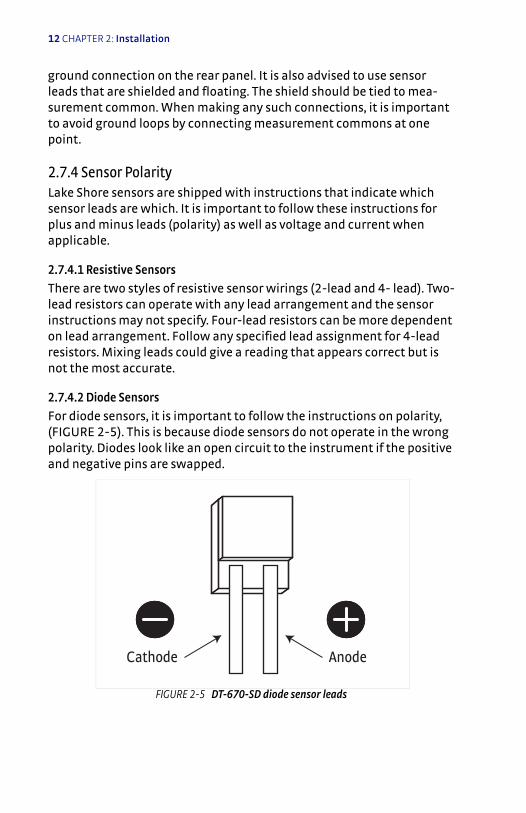
2.7.4.2 Diode Sensors
For diode sensors, it is important to follow the instructions on polarity, (FIGURE 2-5). This is because diode sensors do not operate in the wrong polarity. Diodes look like an open circuit to the instrument if the positive and negative pins are swapped.
FIGURE 2-5 DT-670-SD diode sensor leads
Cathode Anode
13
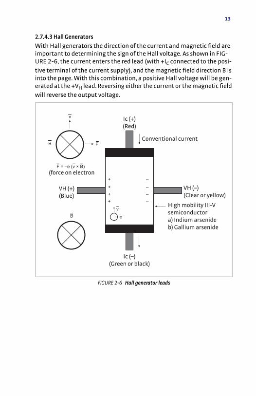
2.7.4.3 Hall Generators
With Hall generators the direction of the current and magnetic field are important to determining the sign of the Hall voltage. As shown in FIG-URE 2-6, the current enters the red lead (with +IC connected to the posi-
tive terminal of the current supply), and the magnetic field direction B is into the page. With this combination, a positive Hall voltage will be gen-erated at the +VH lead. Reversing either the current or the magnetic field will reverse the output voltage.
FIGURE 2-6 Hall generator leads
High mobility III-V semiconductora) Indium arsenideb) Gallium arsenide
VH (–)(Clear or yellow)
VH (+)(Blue)
Ic (–)(Green or black)
Ic (+)(Red)
Conventional current
(force on electron
14 CHAPTER 2: Installation
2.7.5 Lowering Measurement NoiseGood instrument hardware setup technique is one of the least expensive ways to reduce measurement noise. The suggestions fall into two cate-gories: (1) do not let noise from the outside enter into the measurement, and (2) let the instrument isolation and other hardware features work to their best advantage. Here are some further suggestions:
D Do not connect sensor leads to earth ground or chassisD Use twisted shielded cable outside the cooling systemD Attach the chassis to the cable shield and to earth ground if possibleD Use twisted wire inside the cooling systemD Consider ground strapping the instrument chassis to other instru-
ments or computersD Tie all ground points at one common point to avoid ground loopsD For demanding applications, the display can be turned off
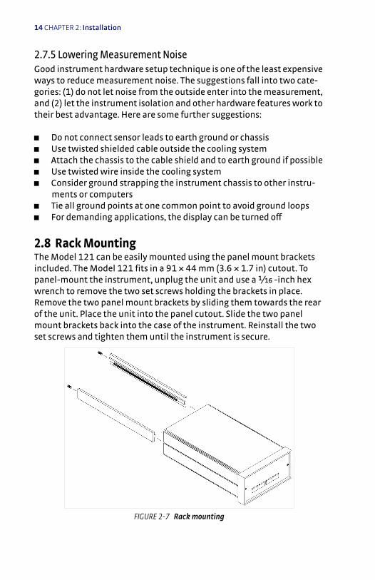
2.8 Rack MountingThe Model 121 can be easily mounted using the panel mount brackets included. The Model 121 fits in a 91 × 44 mm (3.6 × 1.7 in) cutout. To panel-mount the instrument, unplug the unit and use a 1/bg -inch hex wrench to remove the two set screws holding the brackets in place. Remove the two panel mount brackets by sliding them towards the rear of the unit. Place the unit into the panel cutout. Slide the two panel mount brackets back into the case of the instrument. Reinstall the two set screws and tighten them until the instrument is secure.
FIGURE 2-7 Rack mounting

15
Chapter 3: Operation
3.1 GeneralThis chapter provides instructions for the general operating features of the Model 121 current source. Computer interface instructions are in Chapter 4.
3.2 Instrument PowerThe Model 121 is powered on by plugging in the power supply. There is no power switch on the instrument. When the Model 121 is powered on, with no errors present, “121” will illuminate for a few seconds to indi-cate instrument initialization. The instrument powers up in the power up state with the current disabled. Refer to section 3.6. When the instru-ment is powered on for the first time, parameters are set to the factory defaults, listed in TABLE 6-1. The instrument should be powered on for thirty minutes before using for rated specifications.
FIGURE 3-1 Model 121 front panel
16 CHAPTER 3: Operation
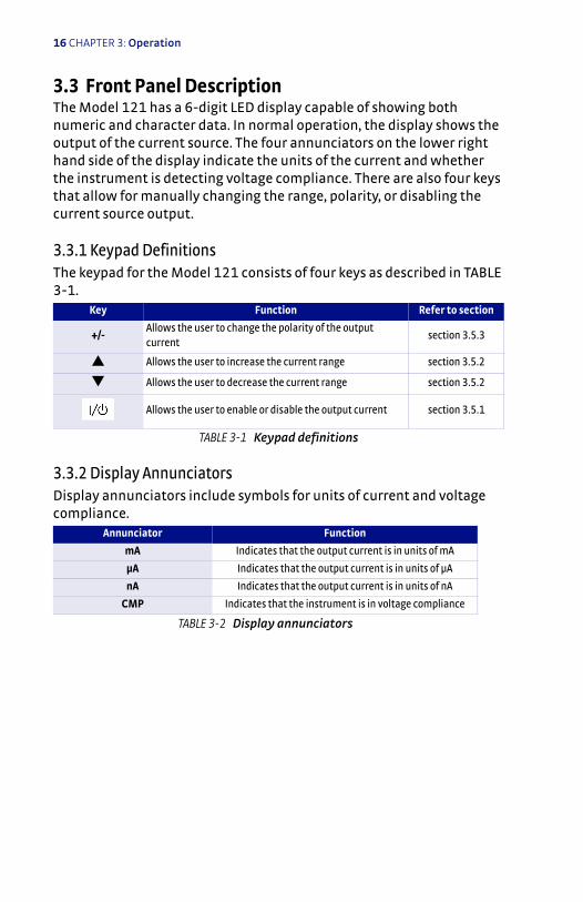
3.3 Front Panel DescriptionThe Model 121 has a 6-digit LED display capable of showing both numeric and character data. In normal operation, the display shows the output of the current source. The four annunciators on the lower right hand side of the display indicate the units of the current and whether the instrument is detecting voltage compliance. There are also four keys that allow for manually changing the range, polarity, or disabling the current source output.
3.3.1 Keypad DefinitionsThe keypad for the Model 121 consists of four keys as described in TABLE 3-1.
3.3.2 Display AnnunciatorsDisplay annunciators include symbols for units of current and voltage compliance.
Key Function Refer to section
+/-Allows the user to change the polarity of the output current
section 3.5.3
Allows the user to increase the current range section 3.5.2
Allows the user to decrease the current range section 3.5.2
Allows the user to enable or disable the output current section 3.5.1
TABLE 3-1 Keypad definitions
Annunciator Function
mA Indicates that the output current is in units of mA
μA Indicates that the output current is in units of µA
nA Indicates that the output current is in units of nA
CMP Indicates that the instrument is in voltage compliance
TABLE 3-2 Display annunciators
17
3.4 Display BrightnessThe front panel 6-digit LED display brightness can be adjusted for opti-mal viewing. The default value, 8, is recommended for most applications. A setting of zero turns the display off, which may reduce noise in sensi-tive measurements. This can only be configured through the computer interface. Refer to Chapter 4.
Menu NavigationBrightness: 0 to 15Default: 8Interface Command: BRIGT
3.5 Output Current SetupThis section explains how to configure the output current through the keypad. Refer to Chapter 4 for information on the computer interface commands. The Model 121 has been optimized to drive resistive sensors (such as Cernox and Platinum Sensors), diode sensors, and Hall genera-tors.
3.5.1 Enable/DisableThe Model 121 allows the user to turn on or turn off the output current
by pressing . When this key is pressed, the display will either read “off” for the disabled state, or the display will show a numeric value for the enabled state. The output current will always power on in the dis-abled state. In this state the instrument will not output any current.
Menu NavigationOutput: Enabled or DisabledDefault: DisabledInterface command: IENBL
3.5.2 Range ChangeThe Model 121 allows for the user to change ranges via the and keys. The range can be changed to any of the 13 fixed ranges or the user current range using these keys. The user current range can be accessed by pressing when in the 100 mA range. The range does not wrap around. For example, when in the USER current range, pressing will do nothing.
18 CHAPTER 3: Operation
When changing to a new range, with the current enabled, the new range will flash for 3 s before setting the new current. For the user current range, the instrument will flash “USER” once, and then it will flash the actual value of the user current twice before changing the output cur-rent. This allows for the user to select a new range directly without applying intermediate ranges. There is no wait time when making a range change through the computer interface. Refer to Chapter 4.
When changing to a new range with the current disabled, the new range will display for 1 s before the display goes back to displaying “OFF”. The new range will be stored in the memory so when the current is enabled the instrument will go to this new range. When reaching the user cur-rent range “USER” will display once before displaying “OFF”.
Menu NavigationRange: 100 nA, 300 nADefault: 100 nAInterface Command: RANGE
3.5.3 Polarity ChangeThe Model 121 allows for the user to switch the polarity of the current by pressing +/-. This key will switch the polarity of the output current for any of the fixed ranges and user current. The +/- key works inde-pendently for the fixed ranges and user current range. Pressing +/- in a fixed range will change the polarity of all fixed ranges, but not the user current. Pressing +/- in the user current range will only change the polar-ity of the user current. The instrument will immediately change the polarity of the current upon receiving a key press.
Menu NavigationPolarity: Positive or NegativeDefault: PositiveInterface Command: IPOL
19
3.5.4 User CurrentThrough the computer interface the Model 121 can be programmed to a current that is between the fixed ranges. This user current is between 100 nA and 100 mA with three digits of resolution. Refer to Chapter 4 to configure the user current setting. When the user range is selected, pressing +/- will change the polarity of the user current, but will not affect the fixed ranges. Refer to section 3.5.3 for more information. The user range is selected by pressing when in the 100 mA range. The dis-play will then flash “USER” once, then it will flash the user current value twice before setting the user current.
User Current: ±100 nA to ±100 mADefault: +100 nAInterface Command: SETI
3.5.5 Power Up EnableThe power up enable feature allows the user to choose whether or not the heater range is turned off each time the instrument power is cycled. Setting the Power Up Enable parameter to Off ensures that the Heater Range is turned off on power up. Setting it to On will return the heater range to its previous setting when power is restored.
Interface Command: PWUPENBL
3.6 Power Up StateThe Model 121 can be programmed to power up in a user defined state called the power up state. The power up state consists of three setup parameters: range, polarity, and user current value. To save the power up state, configure the instrument with the desired settings, then press and hold +/- for 3 s. To save it through the computer interface, refer to chap-ter 4. The power up state will match factory defaults after a factory reset.

20 CHAPTER 3: Operation
3.7 Locking and Unlocking the KeypadThe keypad lock feature prevents accidental changes to parameters. When the keypad is locked, the front panel is completely disabled. To
lock the instrument, hold down for 3 s, until the display reads “LOC”. When the keypad is locked all future key presses will cause the dis-play to read “LOC” for 1 s before returning to the previous display. To
unlock the keypad, hold for 3 s, until the display reads “UnLOC.”
Menu NavigationKeypad: Unlocked or LockedDefault: UnlockedInterface Command: LOCK
21
Chapter 4: Computer Interface Operation
4.1 GeneralThis chapter provides operational instructions for the computer inter-face for the Lake Shore Model 121 Current Source. The Model 121 pro-vides a USB interface described in section 4.2. The Model 121 permits remote operation through the USB interface. The interface commands are detailed in section 4.3.
4.2 USB InterfaceThe Model 121 USB interface provides a convenient way to connect to most modern computers. The USB interface is implemented as a virtual serial com port connection. This implementation provides a simple migration path for modifying existing RS-232 based remote interface software. It also provides a simpler means of communicating than a standard USB implementation.
4.2.1 Physical ConnectionThe Model 121 has a B-type USB connector on the rear panel. This is the standard connector used on USB peripheral devices, and it allows the common USB A-type to B-type cable to be used to connect the Model 121 to a host PC. The pin assignments for A-type and B-type con-nectors are shown in section 6.7. The maximum length of a USB cable, as defined by the USB 2.0 standard, is 5 m (16.4 ft). This length can be extended using USB hubs every 5 m (16.4 ft) up to 5 times, for a maxi-mum total length of 30 m (98.4 ft).
4.2.2 Hardware SupportThe USB interface emulates an RS-232 serial port at a fixed 57,600 baud rate, but with the physical connections of a USB. This programming interface requires a certain configuration to communicate properly with the Model 121. The proper configuration parameters are listed in TABLE 4-1.
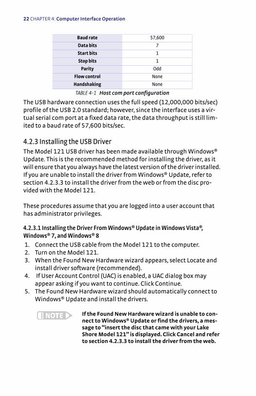
22 CHAPTER 4: Computer Interface Operation
The USB hardware connection uses the full speed (12,000,000 bits/sec) profile of the USB 2.0 standard; however, since the interface uses a vir-tual serial com port at a fixed data rate, the data throughput is still lim-ited to a baud rate of 57,600 bits/sec.
4.2.3 Installing the USB DriverThe Model 121 USB driver has been made available through Windows® Update. This is the recommended method for installing the driver, as it will ensure that you always have the latest version of the driver installed. If you are unable to install the driver from Windows® Update, refer to section 4.2.3.3 to install the driver from the web or from the disc pro-vided with the Model 121.
These procedures assume that you are logged into a user account that has administrator privileges.
4.2.3.1 Installing the Driver From Windows® Update in Windows Vista®, Windows® 7, and Windows® 8
1. Connect the USB cable from the Model 121 to the computer. 2. Turn on the Model 121. 3. When the Found New Hardware wizard appears, select Locate and
install driver software (recommended). 4. If User Account Control (UAC) is enabled, a UAC dialog box may
appear asking if you want to continue. Click Continue. 5. The Found New Hardware wizard should automatically connect to
Windows® Update and install the drivers.
If the Found New Hardware wizard is unable to con-nect to Windows® Update or find the drivers, a mes-sage to “insert the disc that came with your Lake Shore Model 121” is displayed. Click Cancel and refer to section 4.2.3.3 to install the driver from the web.
Baud rate 57,600
Data bits 7
Start bits 1
Stop bits 1
Parity Odd
Flow control None
Handshaking None
TABLE 4-1 Host com port configuration
23
6. When the Found New Hardware wizard finishes installing the driver, a confirmation message stating “the software for this device has been successfully install” will appear. Click Close to complete the installation.
4.2.3.2 Installing the Driver From Windows® Update in Windows® XP
1. Connect the USB cable from the Model 121 to the computer. 2. Turn on the Model 121. 3. When the Found New Hardware wizard appears, select Yes, this
time only and click Next. 4. Select Install the software automatically (Recommended) and click
Next. 5. The Found New Hardware wizard should automatically connect to
Windows® Update and install the drivers.
If the Found New Hardware wizard is unable to con-nect to Windows® Update or find the drivers, a mes-sage saying “Cannot Install this Hardware” is displayed. Click Cancel and refer to section 4.2.3.3 to install the driver from the web.
6. When the Found New Hardware wizard finishes installing the driver a confirmation message stating "the wizard has finished installing the software for Lake Shore Model 121 Current Source" will appear. Click Finish to complete the installation.
4.2.3.3 Installing the Driver from the Web
The Model 121 USB driver is available on the Lake Shore website. To install the driver it must be downloaded from the website and extracted. Use the procedure in section 4.2.3.3.1 through section 4.2.3.3.3to down-load, extract, and install the driver using Windows® XP, Windows Vista®, Windows® 7, and Windows® 8.
4.2.3.3.1 Download the driver 1. Locate the Model 121 USB driver on the downloads page on the Lake
Shore website. 2. Right-click on the USB driver download link, and select save target/
link as. 3. Save the driver to a convenient place, and take note as to where the
driver was downloaded.
24 CHAPTER 4: Computer Interface Operation
4.2.3.3.2 Extract the driverThe downloaded driver is in a ZIP compressed archive. The driver must be extracted from this file. Windows® provides built-in support for ZIP archives. If this support is disabled, a third-party application, such as WinZip™ or 7-Zip, must be used.
For Windows Vista®, Windows® 7, and Windows® 8 1. Right click on the file and click Extract all. 2. An Extract Compressed (Zipped) Folders dialog box will appear. It is
recommended the default folder is not changed. Take note of this folder location.
3. Click to clear the “show extracted files when complete” checkbox, and click Extract.
For Windows® XP 1. Right-click on the file and click extract all. 2. The Extraction wizard will appear. Click Next. 3. It is recommended the default folder is not changed. Take note of
this folder location and click Next. 4. An "Extraction complete" message is displayed. Click to clear the
“show extracted files” checkbox, and click Finish.
4.2.3.3.3 Manually install the driverManually installing drivers differ between versions of Windows®. The fol-lowing sections describe how to manually install the driver using Win-dows® XP, Windows Vista®, Windows® 7, and Windows® 8. To install the driver you must be logged into a user account that has administrator privileges.
For Windows Vista®, Windows® 7, and Windows® 8 1. Connect the USB cable from the Model 121 to the computer. 2. Turn on the Model 121. 3. If the Found New Hardware wizard appears, click “ask me again
later.” 4. Open Device Manager. Use this procedure to open Device Manager.
a. Click the Windows® Start button and type Device Manager in the Start Search box.
b. Click on the Device Manager link in the Search Results Under Programs.
c. If User Account Control is enabled click Continue on the User Account Control prompt.
25
5. Click View and ensure the Devices by Type check box is selected. 6. In the main window of Device Manager, locate Other Devices in the
list of device types. In many instances this will be between Network adapters and Ports (COM & LPT). If the Other Devices item is not already expanded, click the + icon. Lake Shore Model 121 should appear indented underneath Other Devices. If it is not displayed as Lake Shore Model 121, it might be displayed as USB Device. If nei-ther are displayed, click Action and then Scan for hardware changes, which may open the Found New Hardware wizard automatically. If the Found New Hardware wizard opens, click Cancel.
7. Right-click on Lake Shore Model 121 and click Update Driver Soft-ware.
8. Click Browse my computer for driver software. 9. Click Browse and select the location of the extracted driver. 10. Ensure the Include subfolders check box is selected and click Next. 11. When the driver finishes installing a confirmation message stating
"Windows has successfully updated your driver software" should appear.
12. Click Close to complete the installation.
For Windows® XP 1. Connect the USB cable from the Model 121 to the computer. 2. Turn on the Model 121. 3. The Found New Hardware wizard should appear. If the Found New
Hardware wizard does not appear, the following procedure can be used to open the Hardware Update wizard which can be used instead:
a. Open Device Manager. Use this procedure to open the Device Manager:
D Right-click on My Computer and then click Properties. This will open the System Properties dialog.
D Click the Hardware tab and then click Device Manager.
b. Click View and ensure the Devices by Type check box is selected. c. In the main window of Device Manager, locate the Ports (COM &
LPT) device type. In many instances this will be between the Net-work adapters and Processors items. If the Ports (COM & LPT) item is not already expanded, click the + icon. Lake Shore Model 121 should appear indented underneath Ports (COM & LPT). If it
26 CHAPTER 4: Computer Interface Operation
is not displayed as Lake Shore Model 121, it might be displayed as USB Device. If neither are displayed, click Action and then select Scan for hardware changes, which may open the Found New Hardware wizard automatically. If the Found New Hard-ware wizard opens, continue to step 4.
d. Right-click on Lake Shore Model 121 and click Update Driver.
4. Select No, not at this time and click Next. 5. Select Search for the best driver in these locations, click to clear the
Search removable media (floppy, CD-ROM…) check box, and click the Include this location in the search check box.
6. Click Browse and open the location of the extracted driver. 7. Click Next. 8. When the driver finishes installing a confirmation message stating
“The wizard has finished installing the software for Lake Shore Model 121 Current Source” should appear. Click Finish to complete the installation.
4.2.3.4 Installing the USB Driver from the Included CD
The Model 121 USB driver is available on the included CD. The following section describes the process of installing the driver from the CD. To install the driver you must be logged into a user account that has admin-istrator privileges.
For Windows Vista®, Windows® 7, and Windows® 8 1. Insert the CD into the computer. 2. Follow steps 1-9 of the Windows Vista®, Windows® 7, and Windows®
8 procedure in section 4.2.3.3.3. 3. Click Browse and select the drive containing the included CD. 4. Ensure the Include subfolders check box is selected and click Next. 5. When the driver finishes installing a confirmation message stating
"Windows has successfully updated your driver software" will appear. Click Close to complete the installation.
For Windows® XP 1. Insert the CD into the computer. 2. Connect the USB cable from the Model 121 to the computer. 3. Turn on the Model 121. 4. When the Found New Hardware wizard appears select No, not at
this time and click Next. 5. Select Install the software automatically (recommended) and click
Next.
27
6. The Found New Hardware wizard should automatically search the CD and install the drivers.
7. When the Found New Hardware Wizard finishes installing the driv-ers a message stating "the wizard has finished installing the soft-ware for Lake Shore Model 121 Current Source" should appear. Click Finish to complete the installation.
4.2.4 CommunicationCommunicating via the USB interface is done using message strings. The message strings should be carefully formulated by the user program according to some simple rules to establish effective message flow con-trol.
4.2.4.1 Character Format
A character is the smallest piece of information that can be transmitted by the interface. Each character is ten bits long and contains data bits, character timing bits, and an error detection bit. The instrument uses 7 bits for data in the American Standard Code for Information Interchange (ASCII) format. One start bit and one stop bit are necessary to synchro-nize consecutive characters. Parity is a method of error detection. One parity bit configured for odd parity is included in each character.
ASCII letter and number characters are used most often as character data. Punctuation characters are used as delimiters to separate different commands or pieces of data. A special ASCII character, line feed (LF 0AH), is used to indicate the end of a message string. This is called the message terminator.
4.2.4.2 Message Strings
A message string is a group of characters assembled to perform an inter-face function. There are three types of message strings: commands, que-ries and responses. The computer issues command and query strings through user programs, the instrument issues responses. Two or more command or query strings can be chained together in one communica-tion, but they must be separated by a semi-colon (;). The total communi-cation string must not exceed 255 characters in length.
A command string is issued by the computer and instructs the instru-ment to perform a function or change a parameter setting. The format is:
<command mnemonic><space><parameter data><terminators>.
28 CHAPTER 4: Computer Interface Operation
Command mnemonics and parameter data necessary for each one is described in section 4.3. Terminators must be sent with every message string.
A query string is issued by the computer and instructs the instrument to send a response. The query format is:
<query mnemonic><?><space><parameter data><terminators>.
Query mnemonics are often the same as commands with the addition of a question mark. Parameter data is often unnecessary when sending queries. Query mnemonics and parameter data if necessary is described in section 4.3. Terminators must be sent with every message string. The computer should expect a response very soon after a query is sent.
A response string is the instrument's response or answer to a query string. The response can be a reading value, status report or the present value of a parameter. Response data formats are listed along with the associated queries in section 4.3. The response is sent as soon as possible after the instrument receives the query.
4.2.5 Message Flow ControlIt is important to remember that the user program is in charge of the USB communication at all times. The instrument cannot initiate com-munication, determine which device should be transmitting at a given time, or guarantee timing between messages. All of this is the responsi-bility of the user program.
When issuing commands the user program alone should:
D Properly format and transmit the command including the termina-tor as one string
D Guarantee that no other communication is started for 50 ms after the last character is transmitted
D Not initiate communication more than 20 times per second
29
When issuing queries or queries and commands together, the user pro-gram should:
D Properly format and transmit the query including the terminator as one string
D Prepare to receive a response immediatelyD Receive the entire response from the instrument including the ter-
minatorD Guarantee that no other communication is started during the
response or for 50 ms after it completesD Not initiate communication more than 20 times per second
Failure to follow these simple rules will result in inability to establish communication with the instrument or intermittent failures in commu-nication
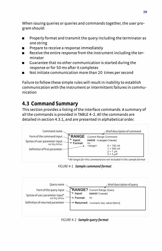
4.3 Command SummaryThis section provides a listing of the interface commands. A summary of all the commands is provided in TABLE 4-2. All the commands are detailed in section 4.3.1, and are presented in alphabetical order.
FIGURE 4-1 Sample command format
FIGURE 4-2 Sample query format
RANGE <range>[term]RANGE
Brief description of commandCommand name
Form of the command input
Syntax of user parameter inputsee key below
Definition of first parameter
Input:Format: nn
<range> 0 = 100 nA
Current Range Command
1 = 300 nA2 = 1 μA3 = 3 μA*
* All ranges for this command are not included in this sample format
RANGE?[term]RANGE?
Brief description of queryQuery name
Form of the query input
Syntax of user parameter input*see key below
Definition of returned parameter
Input:
Format:
Returned:
nn
<numeric key value>[term]
Current Range Query
30 CHAPTER 4: Computer Interface Operation
4.3.1 Interface CommandsThis section lists the interface commands in alphabetical order.
Command Function Page
IDN? Identification Query page 31
RST Reset Instrument Command page 31
BRIGT Display Contrast Command page 31
BRIGT? Display Contrast Query page 31
COMP? Compliance Limit Query page 31
DFLT Factory Defaults Command page 32
IENBL Current Enable Command page 32
IENBL? Current Enable Query page 32
IPOL Polarity Command page 32
IPOL? Polarity Query page 32
LOCK Front Panel Keypad Lock Command page 33
LOCK? Front Panel Keypad Lock Query page 33
RANGE Output Range Command page 33
RANGE? Output Range Query page 34
SETI User Current Setting Command page 34
SETI? User Current Setting Query page 34
SETSAVE Power Up State page 34
TABLE 4-2 Command summary
Begins common interface command
? Required to identify queries
s[n]
String of alphanumeric characters with length “n.” Send these strings using surrounding quotes. Quotes enable characters such as commas and spaces to be used without the instrument interpreting them as delimiters.
nn… String of number characters that may include a decimal point.
[term] Terminator characters
<…> Indicated a parameter field, many are command specific.
<state> Parameter field with only On/Off or Enable/Disable states.
<value>Floating point values have varying resolution depending on the type of command or query issued.
TABLE 4-3 Interface commands key
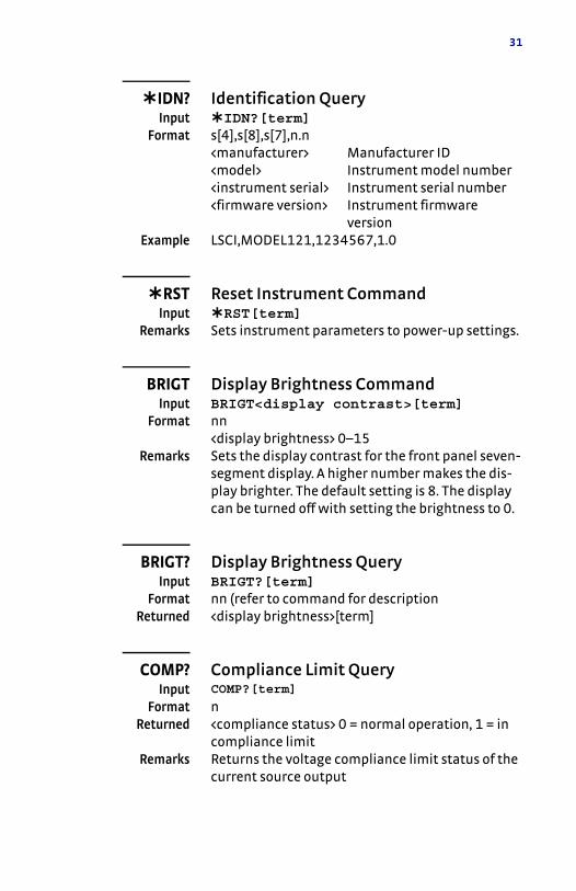
31
IDN? Identification QueryInput IDN?[term]
Format s[4],s[8],s[7],n.n<manufacturer> Manufacturer ID<model> Instrument model number<instrument serial> Instrument serial number<firmware version> Instrument firmware
versionExample LSCI,MODEL121,1234567,1.0
RST Reset Instrument CommandInput RST[term]
Remarks Sets instrument parameters to power-up settings.
BRIGT Display Brightness CommandInput BRIGT<display contrast>[term]
Format nn<display brightness> 0–15
Remarks Sets the display contrast for the front panel seven-segment display. A higher number makes the dis-play brighter. The default setting is 8. The display can be turned off with setting the brightness to 0.
BRIGT? Display Brightness QueryInput BRIGT?[term]
Format nn (refer to command for descriptionReturned <display brightness>[term]
COMP? Compliance Limit QueryInput COMP?[term]
Format n Returned <compliance status> 0 = normal operation, 1 = in
compliance limitRemarks Returns the voltage compliance limit status of the
current source output
32 CHAPTER 4: Computer Interface Operation
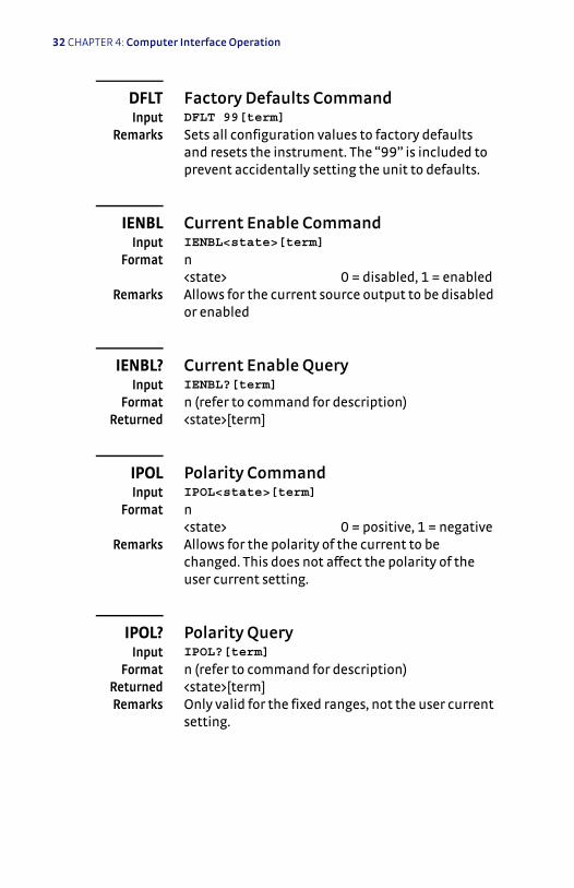
DFLT Factory Defaults CommandInput DFLT 99[term]
Remarks Sets all configuration values to factory defaults and resets the instrument. The “99” is included to prevent accidentally setting the unit to defaults.
IENBL Current Enable CommandInput IENBL<state>[term]
Format n<state> 0 = disabled, 1 = enabled
Remarks Allows for the current source output to be disabled or enabled
IENBL? Current Enable QueryInput IENBL?[term]
Format n (refer to command for description)Returned <state>[term]
IPOL Polarity CommandInput IPOL<state>[term]
Format n<state> 0 = positive, 1 = negative
Remarks Allows for the polarity of the current to be changed. This does not affect the polarity of the user current setting.
IPOL? Polarity QueryInput IPOL?[term]
Format n (refer to command for description)Returned <state>[term]Remarks Only valid for the fixed ranges, not the user current
setting.
33
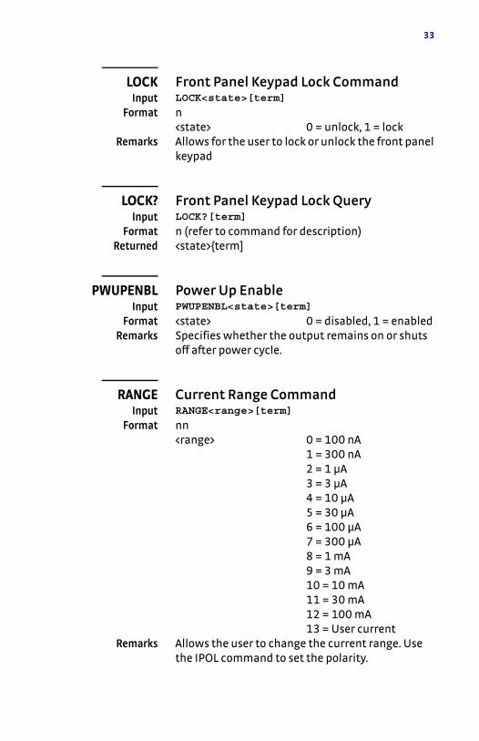
LOCK Front Panel Keypad Lock CommandInput LOCK<state>[term]
Format n<state> 0 = unlock, 1 = lock
Remarks Allows for the user to lock or unlock the front panel keypad
LOCK? Front Panel Keypad Lock QueryInput LOCK?[term]
Format n (refer to command for description)Returned <state>{term]
PWUPENBL Power Up EnableInput PWUPENBL<state>[term]
Format <state> 0 = disabled, 1 = enabledRemarks Specifies whether the output remains on or shuts
off after power cycle.
RANGE Current Range CommandInput RANGE<range>[term]
Format nn<range> 0 = 100 nA
1 = 300 nA2 = 1 µA3 = 3 µA4 = 10 µA5 = 30 µA6 = 100 µA7 = 300 µA8 = 1 mA9 = 3 mA10 = 10 mA11 = 30 mA12 = 100 mA13 = User current
Remarks Allows the user to change the current range. Use the IPOL command to set the polarity.
34 CHAPTER 4: Computer Interface Operation
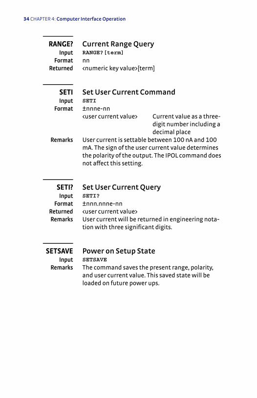
RANGE? Current Range QueryInput RANGE?[term]
Format nnReturned <numeric key value>[term]
SETI Set User Current CommandInput SETI
Format ±nnne-nn<user current value> Current value as a three-
digit number including a decimal place
Remarks User current is settable between 100 nA and 100 mA. The sign of the user current value determines the polarity of the output. The IPOL command does not affect this setting.
SETI? Set User Current QueryInput SETI?
Format ±nnn.nnne-nnReturned <user current value>Remarks User current will be returned in engineering nota-
tion with three significant digits.
SETSAVE Power on Setup StateInput SETSAVE
Remarks The command saves the present range, polarity, and user current value. This saved state will be loaded on future power ups.
35
Chapter 5: Options and Accessories
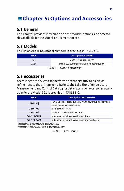
5.1 GeneralThis chapter provides information on the models, options, and accesso-ries available for the Model 121 current source.
5.2 ModelsThe list of Model 121 model numbers is provided in TABLE 5-1.
5.3 AccessoriesAccessories are devices that perform a secondary duty as an aid or refinement to the primary unit. Refer to the Lake Shore Temperature Measurement and Control Catalog for details. A list of accessories avail-able for the Model 121 is provided in TABLE 5-2.
Model Description of Models
121 Model 121 current source
121N Model 121 current source with no power supply
TABLE 5-1 Model description
Model Description of Accessories
109-132*†+5 V DC power supply, 100-240 V, 6 W power supply (universal input, changeable input plugs)
G-106-735 2-pin terminal block
MAN-121* Model 121 current source manual
CAL-121-CERT Instrument recalibration with certificate
CAL-121-DATA Instrument recalibration with certificate and data.
*Accessories included with a new Model 121†Accessories not included with a new Model 121N
TABLE 5-2 Accessories

36 CHAPTER 5: Options and Accessories

37
Chapter 6: Service
6.1 GeneralThis chapter provides basic service information for the Model 121 cur-rent source. Customer service of the product is limited to the informa-tion presented in this chapter. Factory trained service personnel should be consulted if the instrument requires repair.
6.2 USB TroubleshootingThis section provides USB interface troubleshooting for issues that arise with new installations, existing installations, and intermittent lockups.
6.2.1 New Installation 1. Check that the instruments interface is set to USB. 2. Check that the USB driver is installed properly and that the device is
functioning. In Microsoft Windows®, the device status can be checked using Device Manager by right-clicking Lake Shore Model 121 Current Source under Ports (COM & LPT) or Other Devices and then clicking Properties. Refer to section 4.2.3 for details on install-ing the USB driver.
3. Check that the correct com port is being used. In Microsoft Win-dows®, the com port number can be checked using Device Manager under Ports (COM & LPT).
4. Check that the correct settings are being used for communication. Refer to section 4.2.3 for details on installing the USB driver.
5. Check cable connections and length. 6. Send the message terminator. 7. Send the entire message string at one time including the terminator.
(Many terminal emulation programs do not.) 8. Send only one simple command at a time until communication is
established. 9. Be sure to spell commands correctly and use proper syntax.
38 CHAPTER 6: Service
6.2.2 Existing Installation No Longer Working 1. Power the instrument off, then on again to see if it is a soft failure. 2. Power the computer off, then on again to see if communication port
is locked up. 3. Check all cable connections. 4. Check that the com port assignment has not been changed. In Mic-
rosoft Windows®, the com port number can be checked using Device Manager under Ports (COM & LPT).
5. Check that the USB driver is installed properly and that the device is functioning. In Microsoft Windows®, the device status can be checked using Device Manager by right-clicking Lake Shore Model 121 Current Source under Ports (COM & LPT) or Other Devices and then clicking Properties.
6.2.3 Intermittent Lockups 1. Check cable connections and length. 2. Increase the delay between all commands to 100 ms to make sure
the instrument is not being overloaded. 3. Ensure that the USB cable is not unplugged and that the Model 121
is not powered down while the com port is open. The USB driver cre-ates a com port when the USB connection is detected, and removes the com port when the USB connection is no longer detected. Removing the com port while in use by software can cause the soft-ware to lock up or crash.
39
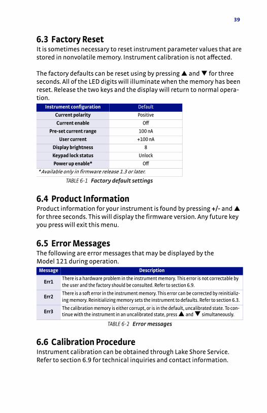
6.3 Factory ResetIt is sometimes necessary to reset instrument parameter values that are stored in nonvolatile memory. Instrument calibration is not affected.
The factory defaults can be reset using by pressing and for three seconds. All of the LED digits will illuminate when the memory has been reset. Release the two keys and the display will return to normal opera-tion.
6.4 Product InformationProduct information for your instrument is found by pressing +/- and for three seconds. This will display the firmware version. Any future key you press will exit this menu.
6.5 Error MessagesThe following are error messages that may be displayed by the Model 121 during operation.
6.6 Calibration ProcedureInstrument calibration can be obtained through Lake Shore Service. Refer to section 6.9 for technical inquiries and contact information.
Instrument configuration Default
Current polarity Positive
Current enable Off
Pre-set current range 100 nA
User current +100 nA
Display brightness 8
Keypad lock status Unlock
Power up enable* Off
* Available only in firmware release 1.3 or later.
TABLE 6-1 Factory default settings
Message Description
Err1There is a hardware problem in the instrument memory. This error is not correctable by the user and the factory should be consulted. Refer to section 6.9.
Err2There is a soft error in the instrument memory. This error can be corrected by reinitializ-ing memory. Reinitializing memory sets the instrument to defaults. Refer to section 6.3.
Err3The calibration memory is either corrupt, or is in the default, uncalibrated state. To con-tinue with the instrument in an uncalibrated state, press and simultaneously.
TABLE 6-2 Error messages
40 CHAPTER 6: Service
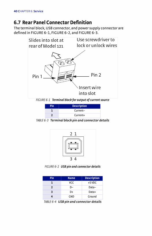
6.7 Rear Panel Connector DefinitionThe terminal block, USB connector, and power supply connector are defined in FIGURE 6-1, FIGURE 6-2, and FIGURE 6-3.
FIGURE 6-1 Terminal block for output of current source
Pin Description
1 Current–
2 Current+
TABLE 6-3 Terminal block pin and connector details
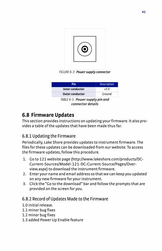
FIGURE 6-2 USB pin and connector details
Pin Name Description
1 VCC +5 VDC
2 D– Data–
3 D+ Data+
4 GND Ground
TABLE 6-4 USB pin and connector details
Pin 1 Pin 2
2 1
3 4
41
6.8 Firmware UpdatesThis section provides instructions on updating your firmware. It also pro-vides a table of the updates that have been made thus far.
6.8.1 Updating the FirmwarePeriodically, Lake Shore provides updates to instrument firmware. The files for these updates can be downloaded from our website. To access the firmware updates, follow this procedure.
1. Go to 121 website page (http://www.lakeshore.com/products/DC-Current-Sources/Model-121-DC-Current-Source/Pages/Over-view.aspx) to download the instrument firmware.
2. Enter your name and email address so that we can keep you updated on any new firmware for your instrument.
3. Click the “Go to the download” bar and follow the prompts that are provided on the screen for you.
6.8.2 Record of Updates Made to the Firmware1.0 initial release.1.1 minor bug fixes1.2 minor bug fixes1.3 added Power Up Enable feature
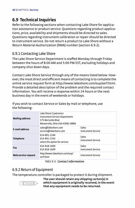
FIGURE 6-3 Power supply connector
Pin Description
Inner conductor +5 V
Outer conductor Ground
TABLE 6-5 Power supply pin and connector details
42 CHAPTER 6: Service
6.9 Technical InquiriesRefer to the following sections when contacting Lake Shore for applica-tion assistance or product service. Questions regarding product applica-tions, price, availability and shipments should be directed to sales. Questions regarding instrument calibration or repair should be directed to instrument service. Do not return a product to Lake Shore without a Return Material Authorization (RMA) number (section 6.9.2).
6.9.1 Contacting Lake ShoreThe Lake Shore Service Department is staffed Monday through Friday between the hours of 8:00 AM and 5:00 PM EST, excluding holidays and company shut down days.
Contact Lake Shore Service through any of the means listed below. How-ever, the most direct and efficient means of contacting is to complete the online service request form at http://www.lakeshore.com/sup/serf.html. Provide a detailed description of the problem and the required contact information. You will receive a response within 24 hours or the next business day in the event of weekends or holidays.
If you wish to contact Service or Sales by mail or telephone, use the following:
6.9.2 Return of EquipmentThe temperature controller is packaged to protect it during shipment.
The user should retain any shipping carton(s) in which equipment is originally received, in the event that any equipment needs to be returned.
Mailing address
Lake Shore CryotronicsInstrument Service Department575 McCorkle Blvd.Westerville, Ohio USA 43082-8888
E-mail [email protected]@lakeshore.com
SalesInstrument Service
Telephone614-891-2244614-891-2243 select the option for service
SalesInstrument Service
Fax614-818-1600614-818-1609
SalesInstrument Service
Web service requesthttp://www.lakeshore.com/sup/serf.html
Instrument Service
TABLE 8-6 Contact information
43
If the original packaging is not available, a minimum of 76.2 mm (3 in) of shock absorbent packing material should be placed snugly on all sides of the instrument in a sturdy corrugated cardboard box. Please use reason-able care when removing the temperature controller from its protective packaging and inspect it carefully for damage. If it shows any sign of damage, please file a claim with the carrier immediately. Do not destroy the shipping container; it will be required by the carrier as evidence to support claims. Call Lake Shore for return and repair instructions.
All equipment returns must be approved by a member of the Lake Shore Service Department. The service engineer will use the information pro-vided in the service request form and will issue an RMA. This number is necessary for all returned equipment. It must be clearly indicated on both the shipping carton(s) and any correspondence relating to the ship-ment. Once the RMA has been approved, you will receive appropriate documents and instructions for shipping the equipment to Lake Shore.
6.9.3 RMA Valid PeriodRMAs are valid for 60 days from issuance; however, we suggest that equipment needing repair be shipped to Lake Shore within 30 days after the RMA has been issued. You will be contacted if we do not receive the equipment within 30 days after the RMA is issued. The RMA will be can-celed if we do not receive the equipment after 60 days.
6.9.4 Shipping ChargesAll shipments to Lake Shore are to be made prepaid by the customer. Equipment serviced under warranty will be returned prepaid by Lake Shore. Equipment serviced out-of-warranty will be returned FOB Lake Shore.
6.9.5 Restocking FeeLake Shore reserves the right to charge a restocking fee for items returned for exchange or reimbursement.

44 CHAPTER 6: Service

45
Appendix A: Handling Liquid Helium and Nitrogen
A.1 GeneralUse of liquid helium (LHe) and liquid nitrogen (LN2) is often associated
with the Model 121 current source. Although not explosive, there are a number of safety considerations to keep in mind in the handling of LHe and LN2.
A.2 PropertiesLHe and LN2 are colorless, odorless, and tasteless gases. Gaseous nitro-gen makes up about 78 percent of the Earth's atmosphere, while helium comprises only about 5 ppm. Most helium is recovered from natural gas deposits. Once collected and isolated, the gases will liquefy when prop-erly cooled. A quick comparison between LHe and LN2 is provided in
TABLE A-1.
Property Liquid Helium Liquid Nitrogen
Boiling Point at 1 atm 4.2 K 77 K
Thermal Conductivity (Gas), w/cm-K 0.083 0.013
Latent Heat of Vaporization, Btu/L 2.4 152
Liquid Density, lb/L 0.275 0.78
TABLE A-1 Comparison of liquid helium and liquid nitrogen

46 APPENDICES
A.3 Handling Cryogenic Storage DewarsCryogenic containers (Dewars) must be operated in accordance with the manufacturer instructions. Safety instructions will also be posted on the side of each Dewar. Cryogenic Dewars must be kept in a well-ventilated place where they are protected from the weather and away from any sources of heat. A typical cryogenic Dewar is shown in FIGURE A-1.
A.4 Liquid Helium and Nitrogen Safety PrecautionsTransferring LHe and LN2 and operation of the storage Dewar controls should be in accordance with the manufacturer/supplier's instructions. During this transfer, it is important that all safety precautions written on the storage Dewar and recommended by the manufacturer be followed.
FIGURE A-1 Typical cryogenic storage Dewar

47
Liquid helium and liquid nitrogen are potential asphyxiants and can cause rapid suffocation without warning. Store and use in area with adequate ventila-tion. DO NOT vent container in confined spaces. DO NOT enter confined spaces where gas may be present unless area has been well ventilated. If inhaled, remove to fresh air. If not breathing, give artificial respiration. If breathing is difficult, give oxygen. Get medical help.
Liquid helium and liquid nitrogen can cause severe frostbite to the eyes or skin. DO NOT touch frosted pipes or valves. In case of frostbite, consult a physi-cian at once. If a physician is not readily available, warm the affected areas with water that is near body temperature.
The two most important safety aspects to consider when handling LHe and LN2 are adequate ventilation and eye and skin protection. Although
helium and nitrogen gases are non-toxic, they are dangerous in that they replace the air in a normal breathing atmosphere. Liquid products are of an even greater threat since a small amount of liquid evaporates to cre-ate a large amount of gas. Therefore, it is imperative that cryogenic Dew-ars be stored and the MTD system be operated in open and well ventilated areas.
Persons transferring LHe and LN2 should make every effort to protect eyes and skin from accidental contact with liquid or the cold gas issuing from it. Protect your eyes with full-face shield or chemical splash gog-gles. Safety glasses (even with side shields) are not adequate. Always wear special cryogenic gloves (Tempshield Cryo-Gloves® or equivalent) when handling anything that is, or may have been, in contact with the liquid or cold gas, or with cold pipes or equipment. Long sleeve shirts and cuffless trousers that are of sufficient length to prevent liquid from entering the shoes are recommended.

48 APPENDICES
A.5 Recommended First AidEvery site that stores and uses LHe and LN2 should have an appropriate Material Safety Data Sheet (MSDS) present. The MSDS may be obtained from the manufacturer/distributor. The MSDS will specify the symptoms of overexposure and the first aid to be used. A typical summary of these instructions is provided as follows.If symptoms of asphyxia such as headache, drowsiness, dizziness, exci-tation, excess salivation, vomiting, or unconsciousness are observed, remove the victim to fresh air. If breathing is difficult, give oxygen. If breathing has stopped, give artificial respiration. Call a physician imme-diately.
If exposure to cryogenic liquids or cold gases occurs, restore tissue to normal body temperature (98.6 °F) as rapidly as possible, then protect the injured tissue from further damage and infection. Call a physician immediately. Rapid warming of the affected parts is best achieved by bathing it in warm water. The water temperature should not exceed 105 °F (40 °C), and under no circumstances should the frozen part be rubbed, either before or after rewarming. If the eyes are involved, flush them thoroughly with warm water for at least 15 minutes. In case of massive exposure, remove clothing while showering with warm water. The patient should not drink alcohol or smoke. Keep warm and rest. Call a physician immediately.

49
Appendix B: Regulatory Declarations
B.1 GeneralDeclarations in this appendix apply to the Lake Shore Cryotronics Model 121 programmable DC current source beginning with serial number 121000A and subsequent, as well as its power supply. Paragraph B1.1 refers to the CE declaration for the Model 121 alone. Paragraphs B1.2 through B1.5 refer to the CE and RoHS declarations respectively for the unit’s power supply.
The declarations included are as follows:D CE declaration for the Model 121D CE declaration for the power supply, P/N 109-132D RoHS declaration for the power supply, P/N 109-132
50 APPENDICES
B.1.1 CE Declaration for Model 121

51
B.1.2 CE Declaration for the Power Supply, Part Number 109-132

52 APPENDICES