Embed Size (px)
Citation preview
USER’S MANUALMITSUBISHI HEAVY INDUSTRIES PACKAGED AIR CONDITIONER
This air-conditioner complies with EMC Directive 2004/108/EC (replaced by 2014/30/EU on 20/4/2016), LV Directive 2006/95/EC (replaced by 2014/35/EU on 20/4/2016).CE marking is applicable to the area of 50 Hz power supply.
Ce climatiseur est conforme à la directive CEM 2004/108/CE (remplacée par la directive 2014/30/UE le 20/04/2016) et à la directive basse tension 2006/95/CE (remplacée par la directive 2014/35/UE le 20/04/2016).La marque CE s’applique aux régions alimentées en courant de 50 Hz.
Dieses Klimagerät erfüllt die Richtlinien zur elektromagnetischen Verträglichkeit 2004/108/EC (ersetzt durch 2014/30/EU am 20/4/2016) und die Niederspannungsrichtlinien 2006/95/EC (ersetzt durch 2014/35/EU am 20/4/2016).Die CE-Marke gilt für Bereiche mit einer Netzstromversorgung von 50 Hz.
Questo condizionatore d’aria è conforme alla Direttiva EMC 2004/108/CE (sostituita dalla Direttiva 2014/30/UE il 20/4/2016) e alla Direttiva LV 2006/95/CE (sostituita dalla Direttiva 2014/35/UE il 20/4/2016).Il marchio CE è applicabile alla fascia di alimentazione 50 Hz.
Deze airconditioner voldoet aan EMC-Richtlijn 2004/108/EC (vervangen door 2014/30/EU op 20/4/2016), LV-Richtlijn 2006/95/EC (vervangen door 2014/35/EU op 20/4/2016).CE-markering is van toepassing op het gebied met een net-stroom van 50 Hz.
Este equipo de aire acondicionado cumple con la Directiva de Compatibilidad Electromagnética: 2004/108/CE (reemplazada por la Directiva 2014/30/EU el 20/4/2016), y con la Directiva de Baja Tensión 2006/95/CE (reemplazada por la Directiva 2014/35/EU el 20/4/2016).La indicación CE sólo corresponde al área de suministro eléctrico de 50 Hz.
Este aparelho de ar condicionado está em conformidade com a Directiva EMC 2004/108/CE (substituída pela 2014/30/UE a 20/4/2016) e a Directiva LV 2006/95/CE (substituída pela 2014/35/UE a 20/4/2016).A marca CE aplica-se à zona de fornecimento de energia a 50 Hz.
Το συγκεκριμένο κλιματιστικό συμμορφώνεται προς την Οδηγία 2004/108/ΕΚ περί ηλεκτρομαγνητικής συμβατότητας (η οποία αντικαταστάθηκε από την Οδηγία 2014/30/ΕΕ στις 20/4/2016) και προς την οδηγία 2006/95/ΕΚ περί χαμηλής τάσης (η οποία αντικαταστάθηκε από την Οδηγία 2014/35/ΕΕ στις 20/4/2016).Tο σήμα CE ισχύει μόνον σε περιοχές όπου η τροφοδοσία είναι 50 Hz.
Ceiling cassette -4 way- (FDT)Ceiling cassette -4 way Compact (600x600mm)- (FDTC)Ceiling cassette -2 way- (FDTW)Ceiling cassette -1 way Compact- (FDTQ)Ceiling cassette -1 way- (FDTS)Duct connected -High static pressure- (FDU)Duct connected -Middle static pressure- (FDUM)Ceiling suspended (FDE)Wall mounted (FDK)Floor standing -2 way- (FDFW)Floor standing (with casing) (FDFL)Floor standing (without casing) (FDFU)Duct connected (Ultra thin) -Low static pressure- (FDQS)Duct connected -Low static pressure- (FDUT)Duct connected -Compact&Flexible- (FDUH)Duct connected -High static pressure outdoor air processing unit (FDU -F)
USER’S MANUAL ENGLISH
MANUEL DE L’UTILISATEUR
ANWENDERHANDBUCH DEUTSCH
ISTRUZIONI PER L’USO ITALIANO
MANUAL DEL PROPIETARIO ESPAÑOL
GEBRUIKERSHANDLEIDING NEDERLANDS
ОΔНГІЕΣ ХРНΣНΣ
MANUAL DO UTILIZADOR PORTUGUÊS
ЕΛΛΗNIKA
РУССКИЙ
FRANÇAIS
РУКОВОДСТВО ПО ЭКСПЛУАТАЦИИ U
KULLANIM KILAVUZU TÜRKÇE
<WIRED REMOTE CONTROL>RC-E5
<eco touch REMOTE CONTROL>RC-EX series
<WIRELESS REMOTE CONTROL>
Please refer to the manual provided with eco touch REMOTE
CONTROL
S'il vous plaît se référer à la documentation fournie avec la
eco touch télécommande
Bitte beachten Sie die Dokumentation, die mit der eco touch
Fernbedienung kam
Si prega di fare riferimento alla documentazione fornita con il
eco touch telecomando
Por favor, consulte la documentación que viene con el eco
touch mando a distancia
Raadpleeg de documentatie die bij de eco touch afstandsbe-
diening
Por favor, consulte a documentação que veio com o eco
touch controle remoto
Ανατρέξτε στην τεκμηρίωση που συνόδευε το eco touch τηλεχειριστήριο
Пожалуйста, обратитесь к документации, поставляемой с eco touch дистанционным управлением
eco touch uzaktan kumanda ile birlikte gelen belgelere bakın
ORIGINAL INSTRUCTIONS
This air-conditioner complies with following directive.Machinery 2006/42/ECLow Voltage 2014/35/EUEMC 2014/30/EUPressure Equipment 2014/68/EURoHS 2011/65/EUEcodesign 2009/125/ECCE marking is applicable to the area of 50 Hz power supply.
Ce climatiseur est conforme aux directives suivantes.Machines 2006/42/CEBasse tension 2014/35/UECEM 2014/30/UEÉquipements sous pression 2014/68/UERoHS 2011/65/UEÉcoconception 2009/125/CELa marque CE s’applique aux régions alimentées en courant de 50 Hz.
Diese Klimaanlage erfüllt die folgende Richtlinie.Maschinen 2006/42/ECNiederspannung 2014/35/EUEMV 2014/30/EUDruckgeräte 2014/68/EURoHS 2011/65/EUÖkodesign 2009/125/ECDie CE-Marke gilt für Bereiche mit einer Netzstromversorgung von 50 Hz.
Questo condizionatore d’aria è conforme alla seguente direttiva.Macchinario 2006/42/CEBassa tensione 2014/35/UEEMC 2014/30/UEApparecchiature a pressione 2014/68/UERoHS 2011/65/UEEcodesign 2009/125/CEIl marchio CE è applicabile alla fascia di alimentazione 50 Hz.
Deze airconditioner voldoet aan de volgende richtlijn.Machine 2006/42/ECLaagspanning 2014/35/EUEMC 2014/30/EUDrukapparatuur 2014/68/EURoHS 2011/65/EUEcodesign 2009/125/ECCE-markering is van toepassing op het gebied met een net-stroom van 50 Hz.
Este aire acondicionado cumple con la siguiente directiva.Máquinas 2006/42/CEBaja tensión 2014/35/UEEMC 2014/30/UEEquipos a presión 2014/68/UERoHS 2011/65/UEEcodiseño 2009/125/CELa indicación CE sólo corresponde al área de suministro eléctrico de 50 Hz.
Este ar condicionado está em conformidade com as seguintes directivas.Máquinas 2006/42/CEBaixa tensão 2014/35/UEEMC 2014/30/UEEquipamentos sob pressão 2014/68/UERoHS 2011/65/UEConcessão ecológica 2009/125/CEA marca CE aplica-se à zona de fornecimento de energia a 50 Hz.
Το συγκεκριμένο κλιματιστικό συμμορφώνεται προς καθεμιά από τις οδηγίες που ακολουθούν.2006/42/ΕΚ περί μηχανημάτων2014/35/ΕΕ περί χαμηλής τάσης2014/30/ΕΕ περί ηλεκτρομαγνητικής συμβατότητας (EMC)2014/68/ΕΕ περί εξοπλισμού υπό πίεση2011/65/ΕΕ RoHS2009/125/ΕΚ περί οικολογικού σχεδιασμούTο σήμα CE ισχύει μόνον σε περιοχές όπου η τροφοδοσία είναι 50 Hz.
PSA012B792B_C_cover.indd 1 2016/08/02 11:58:41
PSA012B820D201611
RLF012A201_Cover.indd 1 10/28/2016 2:54:35 PM
PSA012B820D_cover.indd 1PSA012B820D_cover.indd 1 2016/11/19 14:06:032016/11/19 14:06:03
1
Thank you very much for your purchase of this packaged air conditioning system
produced by Mitsubishi Heavy Industries. Please read through this manual before
using the product and use the product appropriately according to the instructions in
the manual. After you have read the manual, store it with the warranty certifi cate in a
safe place. It will help you when you have questions or problems.
This Product contains fl uorinated greenhouse gases.
Do not vent R410A into the atmosphere: R410A is a fl uorinated greenhouse gas
with a Global Warming Potential (GWP) = 2088.
Refer to a label on outdoor unit for the weight of fl uorinated greenhouse gas and
CO2 equivalent.
SAFETY PRECAUTIONS ...................................................................................................................................................1
HOW TO USE
< WIRED REMOTE CONTROL >
NAMES AND FUNCTIONS OF REMOTE CONTROL BUTTONS
“WIRED REMOTE CONTROL” ...........................................................................................................................................4
HOW TO OPERATE ............................................................................................................................................................5
HOW TO PERFORM THE TIMER OPERATION .................................................................................................................5
THE SELECTION OF TIMER MODE ...............................................................................................................................5
SETTING THE TIME.........................................................................................................................................................6
SLEEP TIMER MODE ......................................................................................................................................................6
OFF TIMER MODE ...........................................................................................................................................................6
ON TIMER MODE ............................................................................................................................................................7
WEEKLY TIMER MODE ...................................................................................................................................................7
TIMER CANCELLATION MODE .....................................................................................................................................10
HOW TO OPERATE IN SILENT MODE ............................................................................................................................10
HOW TO ADJUST THE LOUVER ..................................................................................................................................... 11
HOW TO SET THE AIRFLOW DIRECTION (IN CASE OF FDT, FDTC, FDE, FDK, FDFW) ............................................ 11
HOW TO OPERATE VENTILATION ..................................................................................................................................12
FOR COMFORTABLE USE ..............................................................................................................................................12
INSPECTION DISPLAY, FILTER SIGN, AIR CONDITIONER NUMBER, STANDBY, ROOM TEMPERATURE AND
BACK UP DISPLAY ..........................................................................................................................................................13
< WIRELESS REMOTE CONTROL >
NAMES AND FUNCTIONS OF REMOTE CONTROL BUTTONS
WIRELESS REMOTE CONTROL .....................................................................................................................................13
HOW TO OPERATE ..........................................................................................................................................................14
CURRENT TIME SETTING PROCEDURE ......................................................................................................................14
ON – TIMER OPERATION ................................................................................................................................................14
OFF – TIMER OPERATION ..............................................................................................................................................14
PROGRAM TIMER OPERATION ......................................................................................................................................14
HOW TO ADJUST THE LOUVER ....................................................................................................................................15
FOR COMFORTABLE USE ..............................................................................................................................................15
CHECK INDICATION, FILTER SIGN ................................................................................................................................15
BACKUP BUTTON ............................................................................................................................................................16
FOR SMART USE
HOW TO MAINTAIN ..........................................................................................................................................................16
TROUBLE SHOOTING .....................................................................................................................................................18
NOTICE
PREPARATION OF HEATING ..........................................................................................................................................19
AUTO RESTART ...............................................................................................................................................................19
SETTING TO DISABLE BUTTON OPERATION ...............................................................................................................19
INSTALLATION, RELOCATION, AND INSPECTION MAINTENANCE .............................................................................19
OPERATION RANGE .......................................................................................................................................................19
MAINTENANCE AND INSPECTION GUIDELINE OF MAIN PARTS OF PACKAGED AIR CONDITIONER ....................20
INSTALLATION PRECAUTIONS
DANGERMake sure to have the installation done by your dealer or a specialist.If you install by yourself and the unit is not properly installed, water leakage, electric shock, fi re and injuries caused by the drop of the unit may occur.
SAFETY PRECAUTIONS
Please read these “SAFETY PRECAUTIONS” before starting to use this product and use the product appropriately according to the instructions. The precautions provided here are classified into “ DANGER” and “ CAUTION”. The “ DANGER” sections describe potentially hazardous situations that may lead to serious outcomes such as death and serious injuries if the product is mishandled. Note, however, that depending on the situation, the items listed in the “ CAUTION” sections do also have the potential of causing serious outcomes. Both warnings and cautions provide you important information related to safety ; please make sure to observe them. The symbols used throughout the main text of this manual have the following meaning.
marks mean danger, alarm, and caution. The specifi ed prohibited item is described in the triangle. The left mark means “Shock hazard
alarm”.marks mean prohibited items. The specifi ed prohibited item is described in the circle or in the vicinage. marks mean compulsory action or instruction. The specifi ed prohibited item is described in the circle. The left mark means “Earth is needed”.
After you have read the manual, always store it where other users can refer to at any time. If a new owner takes over the system, make sure to pass this manual.
ENGLISH
The emission sound pressure level from each Indoor and Outdoor unit is under
70 dB(A).
PSA012B820D_EN.indd 1PSA012B820D_EN.indd 1 2016/11/19 14:07:502016/11/19 14:07:50
2
The preventive measures that the density of leaked refrigerant does not exceed the limit is necessary in case of installing the unit in a small room.
The leakage of refrigerant may cause oxygen defi ciency accident. Consult your dealer for the measures.
CAUTION
Make sure to perform grounding work.
Do not connect grounding wire to any gas pipe, water pipe, conductor rods or telephones. Incomplete grounding may cause electric shock through leakage of electricity.
Make sure to mount a leakage breaker.
Otherwise electric shock may occur. Please consult your dealer or a specialist for the mounting.
Do not mount where fl ammable gas leakage can happen.
If leaked gas stagnates in the unit, the gas may cause fi re.
Make sure to layout the drain pipe so that the water is completely drained.
Otherwise, water may leak and wet household goods.
If the unit has been submerged under water due to a natural disaster such as fl ood or typhoon, consult your dealer before using it again.
If you use it as it stands, it may lead to failure, electric shock or fi re.
If any abnormal symptom (scorched fl avor etc.) is found, cut off the power and stop the operation.
Then consult your dealer.
If you use it as it stands, it may lead to failure, electric shock or fi re.
One of the causes of poor cooling or poor heating may be refrigerant leakage. Please consult your dealer.
If the repair requires additional refrigerant, determine the service with the service staff. The refrigerant of air conditioner is not toxic. Normally the refrigerant does not leak. But if it leaks and contacts fi re such as fan heater, space heater or cooking heater, it may produce toxic chemicals.
Do not insert fi ngers or sticks even if air blower does not operate.
It may suddenly operate and cause injuries.
OPERATION PRECAUTIONS
DANGER
This appliance can be used by children aged from 8 years and above and persons with reduced physical, sensory or mental capabilities or lack of experience and knowledge if they have been given supervision or instruction concerning use of the appliance in a safe way and understand the hazards involved.
Children shall not play with the appliance.
Cleaning and user maintenance shall not be made by children without supervision.
Do not expose yourself directly to cooled air fl ow for a long time or cool too much.
It may be cause of deconditioning or health disorder.
Do not insert fi ngers or sticks into the air inlet or outlet grilles.
It may cause injuries because of the fan rotating at high speed.
CAUTION
Do not use for particular purpose such as the storage of food, animals and plants, precision apparatus and arts etc.
Storage goods may degrade.
Do not operate the button with wet hand.
It may cause electric shock.
When a burning appliance is used together with the unit, ventilate frequently.
If ventilation is not sufficient, it may cause oxygen defi ciency accident.
Do not place a burning appliance where the airfl ow from the unit is directly blown.
It may cause the imperfect combustion of the equipment.
Make sure that the unit installation foundation is not damaged due to long-term use.
If it is left to stand, the unit may fall down causing injury.
Do not wash the unit with water, nor place a vase with water on the unit.
It may cause electric shock or ignition.
PSA012B820B_EN.indd 2PSA012B820B_EN.indd 2 2016/08/19 13:36:012016/08/19 13:36:01
3
Do not install the unit where the airfl ow is directly blown to animals and plants.
They may suffer from adverse effect.
Before cleaning, make sure to stop operation and cut off the power.
The fan inside rotates at high speeds.
Make sure to use proper size of fuse.
Using steel wire or copper wire may lead to failure or fi re.
Do not store a fl ammable spray etc. near the unit, nor blow directly to the unit.
It may lead to fi re.
Before maintenance, make sure to stop operation and cut off the power.
The fan inside rotates at high speeds.
When the unit isn’t used for a long-term, cut off the power.
The accumulation of dirt may lead to heat generation or fi re.But, before resuming the operation, turn on the unit for six hours beforehand to save harmless.
Do not operate the air conditioner while the air fi lter is removed.
Piled up dust may lead to malfunction.
During thunderstorm, stop the operation and turn off the switch.
A lightning strike may lead to failure.
After several seasons of operating, inspections and maintenances are required except routine care and cleaning.
Accumulated dirt or dust inside the indoor unit may cause odor, water leakage through the clogging of water discharging pipe for dehumidifi cation. Specialized information and skills are required for inspections and maintenances. Therefore contact your dealer.
Do not place any object around the outdoor unit, nor allow fallen leaves to pile up.
Fallen leaves may induce insects and worms in them, and they may lead to failure, ignition or smoking by touching electric components.
Do not use with inlet/outlet grilles or other panel removed.
Otherwise, it may lead to injuries.
Do not place any other electric appliances or household goods below or around the air conditioner.
Dripping from the unit may lead to failure or contamination.
Do not touch the aluminum fi n.
Otherwise it may lead to injuries.
Do not clean the inside of the indoor unit by yourself. Make sure to consult your dealer or user inquiry counter specifi ed by our company.
If you select incorrect detergent or improper method, resin parts may be damaged and lead to water leakage. If the detergent is dropped on the electric component or motor, it may lead to failure, smoking or ignition.
Do not place objects on the outdoor unit, nor mount on it.
It may lead to injuries resulting from dropping or falling.
During the operation or maintenance, do not use an unstable footrest.
It may lead to injuries resulting from falling.
Be careful so that the dust does not get into your eyes when removing the air fi lter.
Do not operate or stop the unit by using the power supply switch.
It may lead to fi re or water leakage. If auto restart is set effectively, the fan may rotate suddenly causing injuries.
Do not touch blowout port when the swing louver moves.
Otherwise, it may lead to injuries.
Do not strain the remote control cord.
A part of core wire may be cut off causing electric leakage.
Do not use water heater etc. near the indoor unit or remote control.
If a Vapor-generating appliance is used near them, it may lead to water drop causing electric leakage or short circuit.
Do not use the unit where powder or fi ber is fl oating.
Fine powder or fi ber passing through the air fi lter may stagnate inside the unit and lead to electric leak or short circuit.
Do not place objects under the unit which must avoid being exposed to water.
Over 80 percent humidity or the clogging of drain pipe may damage them through dew dropping.
PSA012B820B_EN.indd 3PSA012B820B_EN.indd 3 2016/08/19 13:36:012016/08/19 13:36:01
4
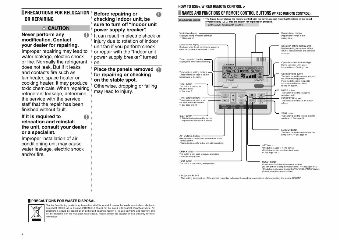
Ventilation displayDisplayed during ventilation operation ☞ See page 12
Weekly timer displayDisplays the settings of the weekly timer.
Operation setting display areaDisplays setting temperature, airflow volume, operation mode and operation message.
Operation/check indicator lightDuring operation: Lit in greenIn case of error: Flashing in red
Operation/stop buttonThis button is used to operate and stop the air conditioning system.Press the button once to operate the system and press it twice to stop the system.
MODE buttonThis button is used to change the operation mode.
FAN SPEED buttonThis button is used to set the airflow volume.
VENT buttonThis button is used to operate external ventilator. ☞ See page 12
LOUVER buttonThis button is used to operate/stop the swing louver. ☞ See page 11
SET buttonfix the setting. set the silent mode.
☞ See page 5 to 12
RESET button
you can go back to the previous operation. ☞ See page 5 to 12
(Press it after cleaning the air filter)
Displayed when the air conditioning system is controlled by centralized remote control.
Timer operation displayDisplays the timer operation setting.
Temperature setting buttonsThese buttons are used to set the temperature of the room.
Timer buttonThis button is used to set the timer mode. ☞ See page 5
Timer setting buttonsThese buttons are used to set the timer mode and the time.☞ See page 5 to 12
E.S.P. buttonThis button is only used by service engineers for installation purposes.
remote control.
This button is only used by service engineers for installation purposes.
TEST buttonThis button is used during test operation.
NAMES AND FUNCTIONS OF REMOTE CONTROL BUTTONS (WIRED REMOTE CONTROL)
Wired remote control • The fi gure below shows the remote control with the cover opened. Note that the items in the liquid crystal display (LCD) area are shown for explanation purpose.
Pull the cover downwards to open.
HOW TO USE< WIRED REMOTE CONTROL >
PRECAUTIONS FOR WASTE DISPOSALYour Air Conditioning product may be marked with this symbol. It means that waste electrical and electronic
equipment (WEEE as in directive 2012/19/EU) should not be mixed with general household waste. Air
conditioners should be treated at an authorized treatment facility for re-use, recycling and recovery and
not be disposed of in the municipal waste stream. Please contact the installer or local authority for more
information.
PRECAUTIONS FOR RELOCATION OR REPAIRING
CAUTION
Never perform any modifi cation. Contact your dealer for repairing.
Improper repairing may lead to water leakage, electric shock or fi re. Normally the refrigerant does not leak. But if it leaks and contacts fi re such as fan heater, space heater or cooking heater, it may produce toxic chemicals. When repairing refrigerant leakage, determine the service with the service staff that the repair has been fi nished without fault.
If it is required to relocation and reinstall the unit, consult your dealer or a specialist.
Improper installation of air conditioning unit may cause water leakage, electric shock and/or fi re.
Before repairing or checking indoor unit, be sure to turn off “Indoor unit power supply breaker”.
It can result in electric shock or injury due to rotation of indoor unit fan if you perform check or repair with the “Indoor unit power supply breaker” turned on.
Place the panels removed for repairing or checking on the stable spot.
Otherwise, dropping or falling may lead to injury.
* IN case of FDU-FThe setting temperature of the remote controller indicates the outdoor temperature while operating thermostat ON/OFF.
PSA012B820B_EN.indd 4PSA012B820B_EN.indd 4 2016/08/19 13:36:012016/08/19 13:36:01
5
HOW TO PERFORM THE TIMER OPERATION < WIRED REMOTE CONTROL >
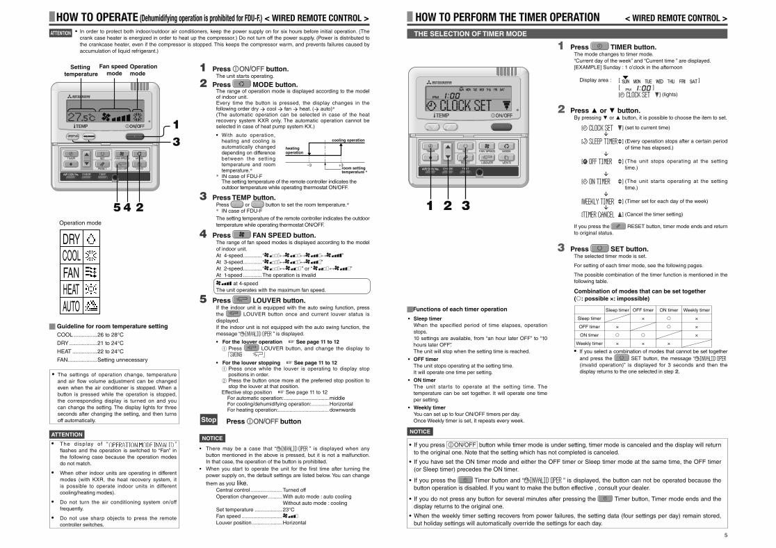
1 Press TIMER button.The mode changes to timer mode.
“Current day of the week” and “Current time ” are displayed.
[EXAMPLE] Sunday : 1 o’clock in the afternoon
Display area : [ ]
[ ]
[ ] (lights)
2 Press or button.By pressing or button, it is possible to choose the item to set.
[ ] (set to current time)
[ ] (Every operation stops after a certain period
of time has elapsed.)
[ ] (The unit stops operating at the setting
time.)
[ ] (The unit starts operating at the setting
time.)
[ ] (Timer set for each day of the week)
[ ] (Cancel the timer setting)
If you press the RESET button, timer mode ends and return
to original status.
3 Press SET button.The selected timer mode is set.
For setting of each timer mode, see the following pages.
The possible combination of the timer function is mentioned in the
following table.
Combination of modes that can be set together
( : possible ×: impossible)
• If you select a combination of modes that cannot be set together
and press the SET button, the message “
(invalid operation)” is displayed for 3 seconds and then the
display returns to the one selected in step 2.
3 2 1
• If you press button while timer mode is under setting, timer mode is canceled and the display will return
to the original one. Note that the setting which has not completed is canceled.
• If you have set the ON timer mode and either the OFF timer or Sleep timer mode at the same time, the OFF timer
(or Sleep timer) precedes the ON timer.
• If you press the Timer button and “ ” is displayed, the button can not be operated because the
button operation is disabled. If you want to make the button effective , consult your dealer.
• If you do not press any button for several minutes after pressing the Timer button, Timer mode ends and the
display returns to the original one.
• When the weekly timer setting recovers from power failures, the setting data (four settings per day) remain stored,
but holiday settings will automatically override the settings for each day.
THE SELECTION OF TIMER MODE
Functions of each timer operation
• Sleep timer
When the specified period of time elapses, operation
stops.
10 settings are available, from “an hour later OFF” to “10
hours later OFF”.
The unit will stop when the setting time is reached.
• OFF timer
The unit stops operating at the setting time.
It will operate one time per setting.
• ON timer
The unit starts to operate at the setting time. The
temperature can be set together. It will operate one time
per setting.
• Weekly timer
You can set up to four ON/OFF timers per day.
Once Weekly timer is set, it repeats every week.
HOW TO OPERATE (Dehumidifying operation is prohibited for FDU-F.) < WIRED REMOTE CONTROL >
NOTICE
• There may be a case that “ ” is displayed when any
button mentioned in the above is pressed, but it is not a malfunction.
In that case, the operation of the button is prohibited.
• When you start to operate the unit for the fi rst time after turning the
power supply on, the default settings are listed below. You can change
them as you like.Central control ......................Turned off
Operation changeover .......... With auto mode : auto cooling
Without auto mode : cooling
Set temperature ...................23°C
Fan speed ............................
Louver position .....................Horizontal
ATTENTION
1 Press button.The unit starts operating.
2 Press MODE button.The range of operation mode is displayed according to the model of indoor unit.Every time the button is pressed, the display changes in the following order dry cool fan heat. ( auto)*(The automatic operation can be selected in case of the heat recovery system KXR only. The automatic operation cannot be selected in case of heat pump system KX.)
• With auto operation, heating and cooling is automatically changed depending on difference between the setting temperature and room temperature.*
* IN case of FDU-FThe setting temperature of the remote controller indicates the outdoor temperature while operating thermostat ON/OFF.
3 Press TEMP button.Press or button to set the room temperature.** IN case of FDU-F
The setting temperature of the remote controller indicates the outdoor
temperature while operating thermostat ON/OFF.
4 Press FAN SPEED button.The range of fan speed modes is displayed according to the model
of indoor unit.
At 4-speed ............. “ ”
At 3-speed ............. “ ”
At 2-speed ............. “ ” or “ ”
At 1-speed .............The operation is invalid
at 4-speed
The unit operates with the maximum fan speed.
5 Press LOUVER button.If the indoor unit is equipped with the auto swing function, press
the LOUVER button once and current louver status is
displayed.
If the indoor unit is not equipped with the auto swing function, the
message “ ” is displayed.
• For the louver operation ☞ See page 11 to 12
1 Press LOUVER button, and change the display to
• For the louver stopping ☞ See page 11 to 121 Press once while the louver is operating to display stop
positions in order.2 Press the button once more at the preferred stop position to
stop the louver at that position.Effective stop position ☞ See page 11 to 12
For automatic operation: ...............................middleFor cooling/dehumidifying operation: ............HorizontalFor heating operation: ................................... downwards
Stop Press button
1 3
2 4 5
Setting temperature
Fan speed mode
Operation mode
Guideline for room temperature setting
COOL ...............26 to 28°C
DRY ..................21 to 24°C
HEAT ................22 to 24°C
FAN ...................Setting unnecessary
• The settings of operation change, temperature
and air fl ow volume adjustment can be changed
even when the air conditioner is stopped. When a
button is pressed while the operation is stopped,
the corresponding display is turned on and you
can change the setting. The display lights for three
seconds after changing the setting, and then turns
off automatically.
• In order to protect both indoor/outdoor air conditioners, keep the power supply on for six hours before initial operation. (The
crank case heater is energized in order to heat up the compressor.) Do not turn off the power supply. (Power is distributed to
the crankcase heater, even if the compressor is stopped. This keeps the compressor warm, and prevents failures caused by
accumulation of liquid refrigerant.)
Operation mode
DRYCOOLFANHEATAUTO
NOTICE
OFF timer
×
×
Sleep timer
×
×
Weekly timer
×
×
×
ON timer
×
Sleep timer
OFF timer
ON timer
Weekly timer
• The display of “ ”
fl ashes and the operation is switched to “Fan” in
the following case because the operation modes
do not match.
• When other indoor units are operating in different
modes (with KXR, the heat recovery system, it
is possible to operate indoor units in different
cooling/heating modes).
• Do not turn the air conditioning system on/off
frequently.
• Do not use sharp objects to press the remote
controller switches.
ATTENTION
cooling operation
heating operation
–3room setting temperature *
+3
PSA012B820B_EN.indd 5PSA012B820B_EN.indd 5 2016/08/19 13:36:012016/08/19 13:36:01
6
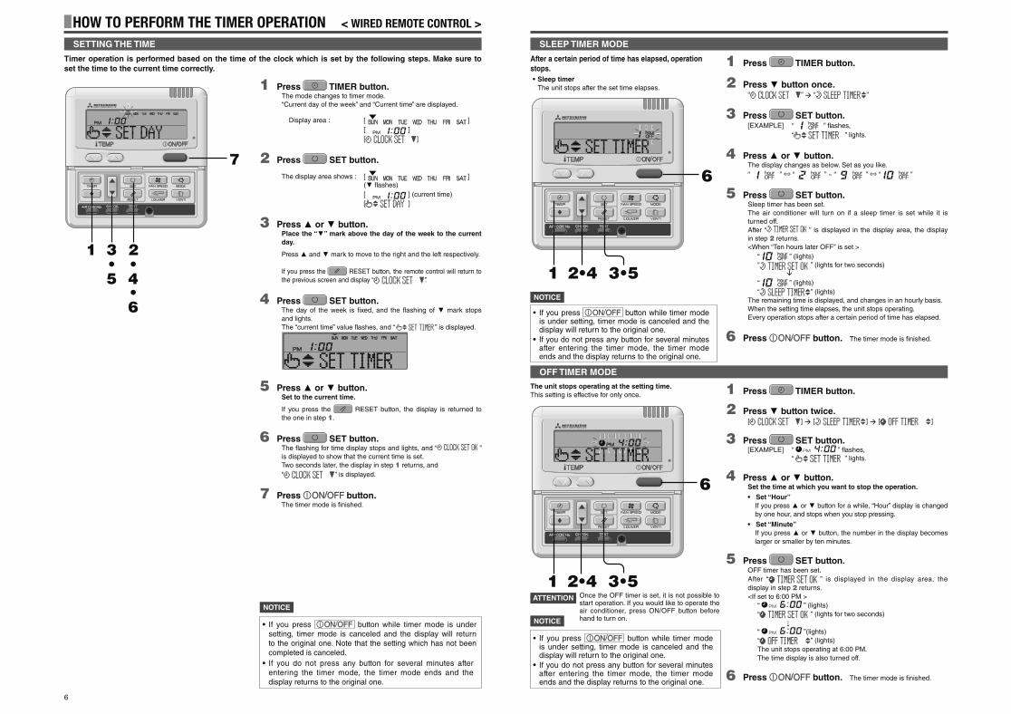
1 Press TIMER button.
2 Press button once.“ ” “ ”
3 Press SET button.[EXAMPLE] “ ” fl ashes,
“ ” lights.
4 Press or button.The display changes as below. Set as you like.
“ ” ⇔ “ ” ~ “ ” ⇔ “ ”
5 Press SET button.Sleep timer has been set.
The air conditioner will turn on if a sleep timer is set while it is
turned off.
After “ ” is displayed in the display area, the display
in step 2 returns.
<When “Ten hours later OFF” is set >
“ ” (lights)
“ ” (lights for two seconds)
“ ” (lights)
“ ” (lights)
The remaining time is displayed, and changes in an hourly basis.
When the setting time elapses, the unit stops operating.
Every operation stops after a certain period of time has elapsed.
6 Press button. The timer mode is fi nished.
3•5 2•4 1
6
1 Press TIMER button.
2 Press button twice.[ ] [ ] [ ]
3 Press SET button.[EXAMPLE] “ ” fl ashes,
“ ” lights.
4 Press or button.Set the time at which you want to stop the operation.
• Set “Hour”
If you press or button for a while, “Hour” display is changed
by one hour, and stops when you stop pressing.
• Set “Minute”
If you press or button, the number in the display becomes
larger or smaller by ten minutes.
5 Press SET button.OFF timer has been set.
After “ ” is displayed in the display area, the
display in step 2 returns.
<If set to 6:00 PM >
“ ” (lights)
“ ” (lights for two seconds)
“ ”(lights)
“ ” (lights)
The unit stops operating at 6:00 PM.
The time display is also turned off.
6 Press button. The timer mode is fi nished.
The unit stops operating at the setting time.
This setting is effective for only once.
3•5 2•4 1
6
Once the OFF timer is set, it is not possible to start operation. If you would like to operate the air conditioner, press ON/OFF button before hand to turn on.
SLEEP TIMER MODE
OFF TIMER MODE
• If you press button while timer mode is under setting, timer mode is canceled and the display will return to the original one.
• If you do not press any button for several minutes after entering the timer mode, the timer mode ends and the display returns to the original one.
• If you press button while timer mode is under setting, timer mode is canceled and the display will return to the original one.
• If you do not press any button for several minutes after entering the timer mode, the timer mode ends and the display returns to the original one.
ATTENTION
After a certain period of time has elapsed, operation
stops.
• Sleep timer
The unit stops after the set time elapses.
NOTICE
HOW TO PERFORM THE TIMER OPERATION < WIRED REMOTE CONTROL >
1 Press TIMER button.The mode changes to timer mode.
“Current day of the week” and “Current time” are displayed.
Display area : [ ]
[ ]
[ ]
2 Press SET button.
The display area shows : [ ]
( fl ashes)
[ ] (current time)
[ ]
3 Press or button.Place the “ ” mark above the day of the week to the current
day.
Press and mark to move to the right and the left respectively.
If you press the RESET button, the remote control will return to
the previous screen and display “ ”.
4 Press SET button.The day of the week is fi xed, and the fl ashing of mark stops
and lights.
The “current time” value fl ashes, and “ ” is displayed.
5 Press or button.Set to the current time.
If you press the RESET button, the display is returned to
the one in step 1.
6 Press SET button.The fl ashing for time display stops and lights, and “ ”
is displayed to show that the current time is set.
Two seconds later, the display in step 1 returns, and
“ ” is displayed.
7 Press button.The timer mode is fi nished.
2 3 1 • • 4 5 • 6
7
Timer operation is performed based on the time of the clock which is set by the following steps. Make sure to
set the time to the current time correctly.
SETTING THE TIME
• If you press button while timer mode is under setting, timer mode is canceled and the display will return to the original one. Note that the setting which has not been completed is canceled.
• If you do not press any button for several minutes after entering the timer mode, the timer mode ends and the display returns to the original one.
NOTICE
NOTICE
PSA012B820B_EN.indd 6PSA012B820B_EN.indd 6 2016/08/19 13:36:032016/08/19 13:36:03
7
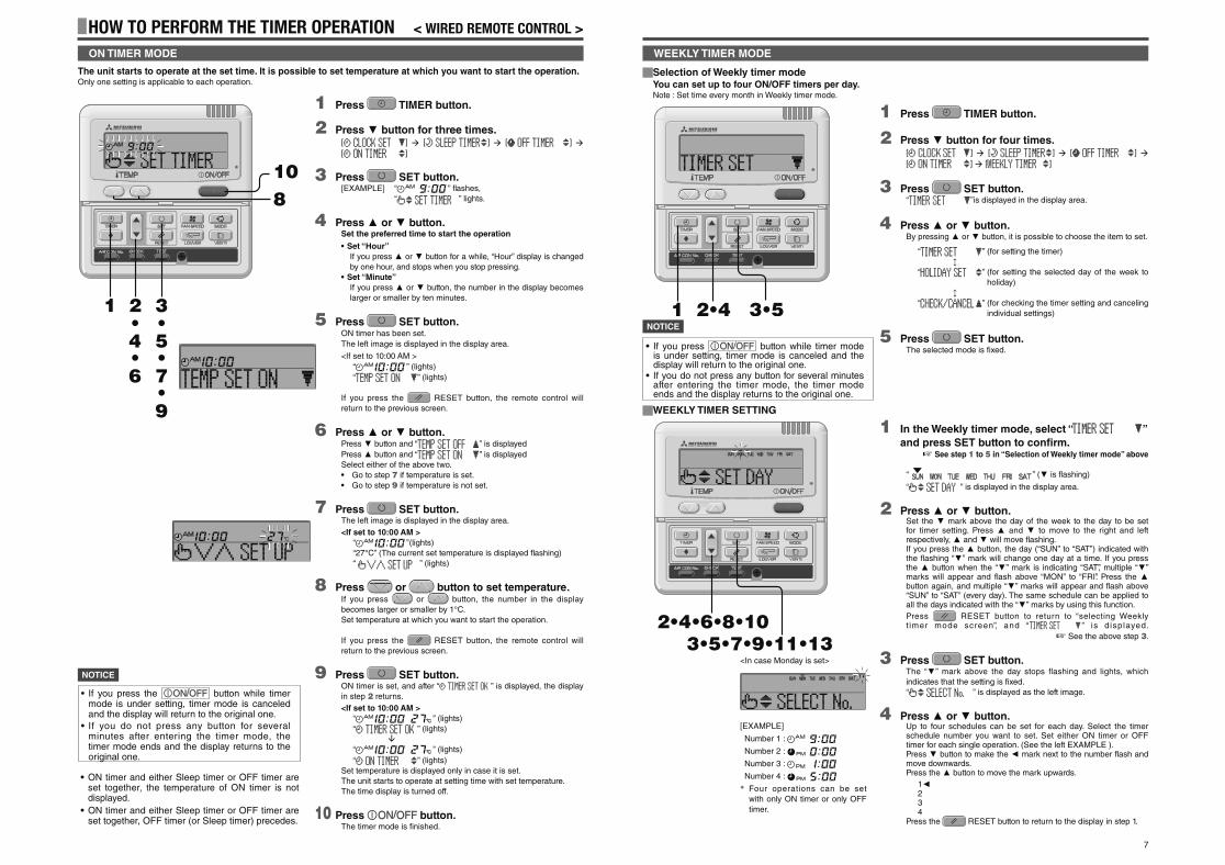
Selection of Weekly timer modeYou can set up to four ON/OFF timers per day.Note : Set time every month in Weekly timer mode.
1 Press TIMER button.
2 Press button for four times.[ ] [ ] [ ]
[ ] [ ]
3 Press SET button.“ ”is displayed in the display area.
4 Press or button.By pressing or button, it is possible to choose the item to set.
“ ” (for setting the timer)
“ ” (for setting the selected day of the week to
holiday)
“ ” (for checking the timer setting and canceling
individual settings)
5 Press SET button.The selected mode is fi xed.
3•5 2•4 1
WEEKLY TIMER SETTING
1 In the Weekly timer mode, select “ ”
and press SET button to confi rm. ☞ See step 1 to 5 in “Selection of Weekly timer mode” above
“ ” ( is flashing)
“ ” is displayed in the display area.
2 Press or button.Set the mark above the day of the week to the day to be set for timer setting. Press and to move to the right and left respectively, and will move fl ashing. If you press the button, the day (“SUN” to “SAT”) indicated with the fl ashing “ ” mark will change one day at a time. If you press the button when the “ ” mark is indicating “SAT”, multiple “ ” marks will appear and fl ash above “MON” to “FRI”. Press the button again, and multiple “ ” marks will appear and fl ash above “SUN” to “SAT” (every day). The same schedule can be applied to all the days indicated with the “ ” marks by using this function.
Press RESET button to return to “selecting Weekly t imer mode screen”, and “ ” is d isplayed.
☞ See the above step 3.
3 Press SET button.The “ ” mark above the day stops flashing and lights, which
indicates that the setting is fi xed.
“ ” is displayed as the left image.
4 Press or button.Up to four schedules can be set for each day. Select the timer schedule number you want to set. Set either ON timer or OFF timer for each single operation. (See the left EXAMPLE ).Press button to make the mark next to the number fl ash and move downwards.Press the button to move the mark upwards.
1234
Press the RESET button to return to the display in step 1.
3•5•7•9•11•13 2•4•6•8•10
WEEKLY TIMER MODE
<In case Monday is set>
• If you press button while timer mode is under setting, timer mode is canceled and the display will return to the original one.
• If you do not press any button for several minutes after entering the timer mode, the timer mode ends and the display returns to the original one.
NOTICE
[EXAMPLE]
Number 1 :
Number 2 :
Number 3 :
Number 4 :
* Four operations can be set
with only ON timer or only OFF
timer.
HOW TO PERFORM THE TIMER OPERATION < WIRED REMOTE CONTROL >
1 Press TIMER button.
2 Press button for three times.[ ] [ ] [ ]
[ ]
3 Press SET button.[EXAMPLE] “ ” fl ashes,
“ ” lights.
4 Press or button.Set the preferred time to start the operation
• Set “Hour”
If you press or button for a while, “Hour” display is changed
by one hour, and stops when you stop pressing.
• Set “Minute”
If you press or button, the number in the display becomes
larger or smaller by ten minutes.
5 Press SET button.ON timer has been set.
The left image is displayed in the display area.
<If set to 10:00 AM >
“ ” (lights)
“ ” (lights)
If you press the RESET button, the remote control will
return to the previous screen.
6 Press or button.Press button and “ ” is displayed
Press button and “ ” is displayed
Select either of the above two.
• Go to step 7 if temperature is set.
• Go to step 9 if temperature is not set.
7 Press SET button.The left image is displayed in the display area.
<If set to 10:00 AM >
“ ”(lights)
“27°C” (The current set temperature is displayed fl ashing)
“ ” (lights)
8 Press or button to set temperature.If you press or button, the number in the display
becomes larger or smaller by 1°C.
Set temperature at which you want to start the operation.
If you press the RESET button, the remote control will
return to the previous screen.
9 Press SET button.ON timer is set, and after “ ” is displayed, the display
in step 2 returns.
<If set to 10:00 AM >
“ ” (lights)
“ ” (lights)
“ ” (lights)
“ ” (lights)
Set temperature is displayed only in case it is set.
The unit starts to operate at setting time with set temperature.
The time display is turned off.
10 Press button.The timer mode is fi nished.
10 8
3 2 1 • • 5 4
7 6 •
9 •
•
The unit starts to operate at the set time. It is possible to set temperature at which you want to start the operation.Only one setting is applicable to each operation.
ON TIMER MODE
• ON timer and either Sleep timer or OFF timer are set together, the temperature of ON timer is not displayed.
• ON timer and either Sleep timer or OFF timer are set together, OFF timer (or Sleep timer) precedes.
• If you press the button while timer mode is under setting, timer mode is canceled and the display will return to the original one.
• If you do not press any button for several minutes after entering the timer mode, the timer mode ends and the display returns to the original one.
NOTICE
PSA012B820B_EN.indd 7PSA012B820B_EN.indd 7 2016/08/19 13:36:042016/08/19 13:36:04
8
• If you select a day of the week for which setting
have already been made, all the timer numbers
that have been set are displayed. And the details
of the timer setting for the number which has “ ”
mark is displayed. You can modify the selected
setting by overwriting it.
• If you set ON timer and OFF timer operating at
the same time, OFF timer will precede.
• If the same two times are set for ON timer on the
same day, the lower number precedes.
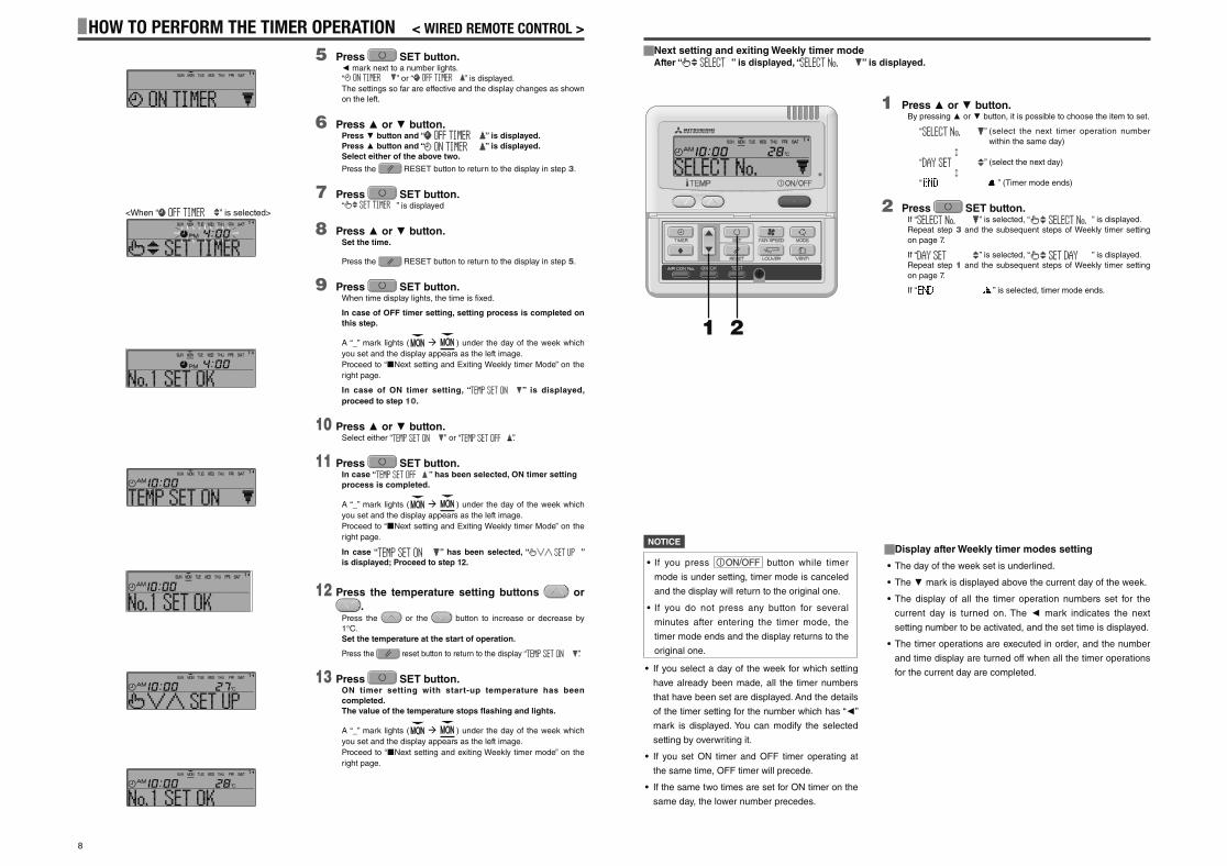
Next setting and exiting Weekly timer modeAfter “ ” is displayed, “ ” is displayed.
1 Press or button.By pressing or button, it is possible to choose the item to set.
“ ” (select the next timer operation number
within the same day)
“ ” (select the next day)
“ ” (Timer mode ends)
2 Press SET button.If “ ” is selected, “ ” is displayed.
Repeat step 3 and the subsequent steps of Weekly timer setting
on page 7.
If “ ” is selected, “ ” is displayed.
Repeat step 1 and the subsequent steps of Weekly timer setting
on page 7.
If “ ” is selected, timer mode ends.
2 1
Display after Weekly timer modes setting
• The day of the week set is underlined.
• The mark is displayed above the current day of the week.
• The display of all the timer operation numbers set for the
current day is turned on. The mark indicates the next
setting number to be activated, and the set time is displayed.
• The timer operations are executed in order, and the number
and time display are turned off when all the timer operations
for the current day are completed.
• If you press button while timer
mode is under setting, timer mode is canceled
and the display will return to the original one.
• If you do not press any button for several
minutes after entering the timer mode, the
timer mode ends and the display returns to the
original one.
NOTICE
HOW TO PERFORM THE TIMER OPERATION < WIRED REMOTE CONTROL >
5 Press SET button. mark next to a number lights.
“ ” or “ ” is displayed.
The settings so far are effective and the display changes as shown
on the left.
6 Press or button.Press button and “ ” is displayed.
Press button and “ ” is displayed.
Select either of the above two.
Press the RESET button to return to the display in step 3.
7 Press SET button.“ ” is displayed
8 Press or button.Set the time.
Press the RESET button to return to the display in step 5.
9 Press SET button.When time display lights, the time is fi xed.
In case of OFF timer setting, setting process is completed on
this step.
A “_” mark lights ( ) under the day of the week which
you set and the display appears as the left image.
Proceed to “ Next setting and Exiting Weekly timer Mode” on the
right page.
In case of ON timer setting, “ ” is displayed,
proceed to step 10.
10 Press or button.Select either “ ” or “ ”.
11 Press SET button.In case “ ” has been selected, ON timer setting
process is completed.
A “_” mark lights ( ) under the day of the week which
you set and the display appears as the left image.
Proceed to “ Next setting and Exiting Weekly timer Mode” on the
right page.
In case “ ” has been selected, “ ”
is displayed; Proceed to step 12.
12 Press the temperature setting buttons or
.Press the or the button to increase or decrease by
1°C.
Set the temperature at the start of operation.
Press the reset button to return to the display “ ”.
13 Press SET button.ON timer setting with start-up temperature has been
completed.
The value of the temperature stops fl ashing and lights.
A “_” mark lights ( ) under the day of the week which
you set and the display appears as the left image.
Proceed to “ Next setting and exiting Weekly timer mode” on the
right page.
<When “ ” is selected>
PSA012B820B_EN.indd 8PSA012B820B_EN.indd 8 2016/08/19 13:36:062016/08/19 13:36:06
9
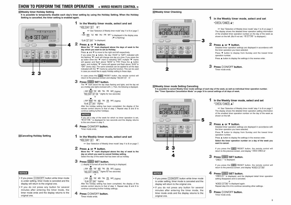
Weekly timer Checking
1 In the Weekly timer mode, select and set
“ ”.
☞ See “Selection of Weekly timer mode” step 1 to 5 on page 7.
The display shows the detailed timer operation setting information
of the smallest timer operation number on the day of the week as
shown on the left. (But if not set, “ ” is displayed.)
2 Press or button.Detailed timer operation settings are displayed in accordance with
the timer operation you have selected.
Press button to display from Sunday and the lowest timer
operation number.
Press button to display the settings in the reverse order.
3 Press button.Timer mode ends.2
3
Weekly timer mode Setting CancelingIt is possible to cancel Weekly timer mode settings of each day of the week, as well as individual timer operation number.
See “Timer Operation Cancellation Mode” on page 10 to cancel settings of all days of week.
1 In the Weekly timer mode, select and set
“ ”.
☞ See “Selection of Weekly timer mode” step 1 to 5 on page 7.
The display shows the detailed timer operation setting information
of the smallest timer operation number on the day of the week as
shown on the left.
2 Press or button.Detailed timer operation settings are displayed in accordance with
the timer operation you have selected.
Press button to display from Sunday and the lowest timer
operation number.
Press button to display the settings in the reverse order.
Select the timer operation number on a day of the week you
want to cancel.
If you press the RESET button, the remote control will
return to the previous screen, and display “ ”.
3 Press SET button.“ ” is displayed.
If you press the RESET button, the remote control will
return to the previous screen, and display “ ”.
4 Press SET button.“ ” is displayed, and the displayed detail timer operation
setting disappears and is canceled.
“ ” is displayed again.
Repeat step 2 to 4 to continue canceling other settings.
5 Press button.Timer mode ends.
2
5
3 • 4
• If you press button while timer mode
is under setting, timer mode is canceled and the
display will return to the original one.
• If you do not press any button for several
minutes after entering the timer mode, the
timer mode ends and the display returns to the
original one.
NOTICE
Canceling Holiday Setting
HOW TO PERFORM THE TIMER OPERATION < WIRED REMOTE CONTROL >Weekly timer Holiday SettingIt is possible to temporarily disable each day’s timer setting by using the Holiday Setting. When the Holiday
Setting is cancelled, the timer setting is enabled again.
1 In the Weekly timer mode, select and set
“ ”.
☞ See “Selection of Weekly timer mode” step 1 to 5 on page 7.
“ ” is displayed in the display area
( is flashing)
“ ” is displayed.
2 Press or button.Move the “ ” mark displayed above the days of week to the
day which you want to set as Holiday.
Press and to move to the right and left respectively.
If you press the button, the day (“SUN” to “SAT”) indicated with the fl ashing “ ” mark will change one day at a time. If you press the
button when the “ ” mark is indicating “SAT”, multiple “ ” marks will appear and fl ash above “MON” to “FRI”. Press the button again, and multiple “ ” marks will appear and fl ash above “SUN” to “SAT” (every day). The same schedule can be applied to all the days indicated with the “ ” marks by using this function. This can be used in case you would like to apply Holiday setting to these days.
In case press the RESET button, the remote control will return to the previous screen and display “ ”.
3 Press SET button.The “ ” mark above the day stops fl ashing and lights, and the day set as a holiday also lights enclosed with ( ). Then, the following is displayed.
[ ] (lights)
“ ” (lights for two seconds)
[ ] (lights)
“ ”(lights)
After the holiday setting has been completed, the display of the remote control returns to that of step 1. Repeat step 2 and 3 to continue setting further holidays.
NOTICE
If you set a day of the week for which no timer operation is set, “ ” is displayed for two seconds and the display returns to the one shown in step 1.
4 Press button.Timer mode ends.
3 2
4
1 In the Weekly timer mode, select and set
“ ”.
☞ See “Selection of Weekly timer mode” step 1 to 5 on page 7.
2 Press or button.Move the “ ” mark displayed above the day of week to the
day on which you want to cancel Holiday setting.
Select the day of the week that has been set as holiday.
3 Press SET button.( ) display is turned off and the following is displayed.
[ ] (lights)
“ ” (lights for two seconds)
[ ] (lights)
“ ” (lights)
After the holiday setting has been completed, the display of the
remote control returns to that of step 1. Repeat step 2 and 3 to
continue canceling further holiday settings.
4 Press button.Timer mode ends.
• If you press button while timer mode
is under setting, timer mode is canceled and the
display will return to the original one.
• If you do not press any button for several
minutes after entering the timer mode, the
timer mode ends and the display returns to the
original one.
NOTICE
PSA012B820B_EN.indd 9PSA012B820B_EN.indd 9 2016/08/19 13:36:072016/08/19 13:36:07
10
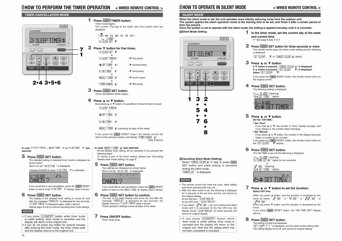
HOW TO OPERATE IN SILENT MODE < WIRED REMOTE CONTROL >
1 In the timer mode, set the current day of the week
and current time.☞ See page 6 step 1 to 7
2 Press SET button for three seconds or more.The remote control goes into silent mode setting and the following
is displayed.
“ ” or “ ” (lights)
3 Press or button.If button is pressed, “ ” is displayed.
If button is pressed, “ ” is displayed.
Select “ ”.
If you press the RESET button, the remote control return to
the original screen.
4 Press SET button.The following setting is displayed.
“ ” (fl ashing)
“ ” (lights)
5 Press or button.Set the “ON TIME”.
• Set “Hour”
If you hold or , the number in “Hour” display changes, and
if you release it, the number stops changing.
• Set “Minute”
If you press or button, the number in the display becomes
larger or smaller by ten minutes.
If you press the RESET button, the remote control return to
the “ ” display.
6 Press SET button.The ON TIME is set and the following is displayed.
“ ” (fl ashing)
“ ” (lights for two seconds)
“ ” (fl ashing)
“ ” (lights)
7 Press or button to set the duration.Select OFF time.
When you press button, and the duration is increased by two
hours as below, “ ” “ ” “ ”
“ ”
When you press button, and the duration is decreased by two
hours.
If you press RESET button, the “ON TIME SET” display
returns.
8 Press SET button.The setting is fi xed and displayed.
“ ” is displayed, and the silent mode setting ends.
The setting display turns off, and returns to original display.
3 • 5 • 7
2 • 4 • 6 • 8
1
When the silent mode is set, the unit operates more silently reducing noise from the outdoor unit.The system applies the silent operation mode at the starting time to be set, and fi nish it after a certain period of time has passed.Once the system is set to operate with the silent mode, the setting is applied everyday until it is canceled.
NOTICE
• The remote control has main-sub units, silent setting
cannot be operated with sub unit .
• After the silent mode is set, the following is displayed
for 3 seconds at the set time and the unit returns to
the original display.
At the ON time : “ ”
At the OFF time : “ ”
• If you select “ ”, you can continue the silent
mode until it is canceled. At the fi rst ON time, the
display shows “ ” for three seconds and
returns to original display.
Canceling Silent Mode (Setting)
Select “ ” in step 2, press
SET button and silent setting is canceled
ending the silent mode.
“ ” is displayed.
SILENT MODE
Silent Mode Setting
• I f you press button while timer mode is under setting, timer mode is canceled and the display will return to the original one. Note that the setting which has not been completed is canceled.
HOW TO PERFORM THE TIMER OPERATION < WIRED REMOTE CONTROL >
TIMER CANCELLATION MODE
2•4
7 1
3•5•6
In case “ ” , “ ” or “ ” was
selected.
5 Press SET button.The detailed setting of selected timer mode is displayed as
shown below.
(But if not set, “ ” is displayed)
<Display EXAMPLE when “ ” is selected>
If you would like to quit cancellation, press the RESET
button to return to the “ ” display. (step 4 above)
6 Press SET button.The display of the detailed timer setting is turned off, and
after the message “ ” is displayed for two seconds,
“ ” is displayed again. (step 4 above)
Repeat steps 4 to 6 to continue canceling timer mode settings.
In case “ ” was selected.All the Weekly timer setting will be canceled if you proceed the
following steps.
To cancel a part of the timer setting, please see “Canceling
Weekly timer mode Setting” on page 9.
5 Press SET button.The settings are displayed as shown below.
(But if not set, “ ” is displayed)
If you would like to quit cancellation, press the RESET
button to return to the “ ” display. (step 4 above)
6 Press SET button to confi rm.The day of the week display area turns off, and after the message “ ” is displayed for two seconds, the display returns to “ ”. (step 4 above)These operation settings cancel all days of the week.
1 Press TIMER button.Timer mode begins.
The current “The day of the week” and “the current time” are
displayed.
[ ]
“ ”
“ ”
2 Press button for fi ve times.“ ”
“ ” ( fi rst press)
“ ” ( second press)
“ ” ( third press)
“ ” ( fourth press)
“ ” ( fi fth press)
3 Press SET button.Timer Cancellation Mode begins.
4 Press or button.By pressing or button, it is possible to choose the item to cancel.
“ ”
“ ”
“ ”
“ ” (canceling all days of the week)
If you press the RESET button, the remote control will
return to the previous screen, and display “ ”.
(step 2 above)
7 Press ON/OFF button.Timer mode ends.
• If you press button while timer mode is under setting, timer mode is canceled and the display will return to the original one.
• If you do not press any button for several minutes after entering the timer mode, the timer mode ends and the display returns to the original one.
NOTICE
PSA012B820B_EN.indd 10PSA012B820B_EN.indd 10 2016/08/19 13:36:082016/08/19 13:36:08
11
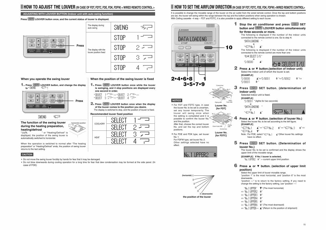
Press LOUVER button once, and the current status of louver is displayed.
ADJUSTING WITH LOUVER BUTTON (Indoor unit with auto swing function)
HOW TO ADJUST THE LOUVER (IN CASE OF FDT, FDTC, FDE, FDK, FDFW) < WIRED REMOTE CONTROL >
The display during auto swing
The display with the louver position fixed
When you operate the swing louver
1. Press LOUVER button, and change the display
to “ ”.
The function of the swing louver
during the heating preparation,
heating/defrost“ ” or “Heating/Defrost” is
displayed, the position of the swing louver is
automatically switched to horizontal.
When the operation is switched to normal after “The heating
preparation” or “Heating/Defrost” ends, the position of swing louver
returns to the last setting.
When the position of the swing louver is fi xed
1. Press LOUVER button once while the louver
is swinging, and 4 stop positions are displayed every
one second in order.
“ ” “ ”
“ ” “ ”
2. Press LOUVER button once when the display
of the louver comes to the position you desire. The display is switched to stop, and the position of louver is fi xed.
Recommended louver fi xed position
COOL•DRY
HEAT
horizontal position
1 Stop the air conditioner and press SET
button and LOUVER button simultaneously
for three seconds or more.The following is displayed if the number of the indoor units
connected to the remote control is one. Go to step 4.
“ ”
“ ”
The following is displayed if the number of the indoor units
connected to the remote control are more than one
“ ”
“ ”
2 Press or button.(selection of indoor unit)Select the indoor unit of which the louver is set.
[EXAMPLE]
“ ”⇔“ ”⇔“ ”⇔“ ”
3 Press SET button. (determination of
indoor unit)Selected indoor unit is fi xed.
[EXAMPLE]
“ ” (lights for two seconds)
“ ”
“ ”
4 Press or button. (selection of louver No.)Select the louver No. to be set according to the left fi gure.
[EXAMPLE]
“ ” ⇔ “ ” ⇔ “ ” ⇔ “ ”
Note : For FDE, select “ ”. Other louver No. settings
have no effect.
5 Press SET button. (Determination of
louver No.)The louver No. to be set is confi rmed and the display shows the
upper limit of the movable range.
[EXAMPLE] If No.1 louver is selected,
“ ” current upper limit position
6 Press or button. (selection of upper limit
position)Select the upper limit of louver movable range.
“position 1” is the most horizontal, and “position 6” is the most
downwards.
“position --” is to return to the factory setting. If you need to
change the setting to the factory setting, use “position --”.
“ ” (The most horizontal)
⇔ “ ”
⇔ “ ”
⇔ “ ”
⇔ “ ”
⇔ “ ” (The most downward)
⇔ “ ” (Return to the position of shipment)
2•4•6•8 1
10
3•5•7•9
HOW TO SET THE AIRFLOW DIRECTION (IN CASE OF FDT, FDTC, FDE, FDK, FDFW) <WIRED REMOTE CONTROL>
No. 4
No. 2
No. 1
No. 3
Control box
Piping sideDrain
hose side
Louver No.
[for FDT]
It is possible to change the movable range of the louver on the air outlet from the wired remote control. Once the top and bottom positions
are set, the louver will swing within the range between the top and the bottom positions when swing operation is chosen.
With Ceiling cassette −4 way − FDT and FDTC, it is also possible to apply different setting to each louver.
NOTICE
• For FDT and FDTC type, in case
the louver No. to be set is uncertain,
set any louver temporarily. The
louver wi l l swing once when
the setting is completed and it is
possible to confi rm the louver No.
and the position.
After that, choose the correct louver
No. and set the top and bottom
positions.
• For FDE and FDK type, set louver
No. 1.
For FDFW type, set louver No. 2.
Other settings selected have no
effect.
(downwards)
(horizontal)
the position of the louver
Press
Press
CAUTION
• Do not move the swing louver forcibly by hands for fear that it may be damaged.
• Do not blow downwards during cooling operation for a long time for fear that dew condensation may be formed at the side panel. (In
case of FDE)
No. 4
No. 2
No. 1
No. 3
Control box
Piping sideDrain hose side
Louver No.
[for FDTC]
PSA012B820B_EN.indd 11PSA012B820B_EN.indd 11 2016/08/19 13:36:102016/08/19 13:36:10
12
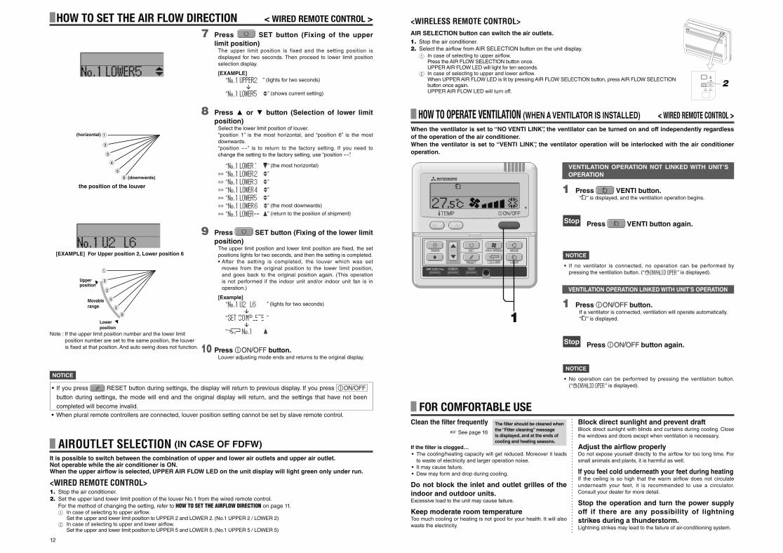
7 Press SET button (Fixing of the upper
limit position)The upper limit position is fixed and the setting position is
displayed for two seconds. Then proceed to lower limit position
selection display.
[EXAMPLE]
“ ” (lights for two seconds)
“ ” (shows current setting)
8 Press or button (Selection of lower limit
position)Select the lower limit position of louver.
“position 1” is the most horizontal, and “position 6” is the most
downwards.
“position --” is to return to the factory setting. If you need to
change the setting to the factory setting, use “position --”.
“ ” (the most horizontal)
⇔ “ ”
⇔ “ ”
⇔ “ ”
⇔ “ ”
⇔ “ ” (the most downwards)
⇔ “ ” (return to the position of shipment)
9 Press SET button (Fixing of the lower limit
position)The upper limit position and lower limit position are fi xed, the set
positions lights for two seconds, and then the setting is completed.
• After the setting is completed, the louver which was set
moves from the original position to the lower limit position,
and goes back to the original position again. (This operation
is not performed if the indoor unit and/or indoor unit fan is in
operation.)
[Example]
“ ” (lights for two seconds)
“ ”
“
10 Press button.Louver adjusting mode ends and returns to the original display.
HOW TO SET THE AIR FLOW DIRECTION < WIRED REMOTE CONTROL >
NOTICE
(downwards)
(horizontal)
the position of the louver
[EXAMPLE] For Upper position 2, Lower position 6
Lower position
Movable range
Upper position
• When plural remote controllers are connected, louver position setting cannot be set by slave remote control.
• If you press RESET button during settings, the display will return to previous display. If you press
button during settings, the mode will end and the original display will return, and the settings that have not been
completed will become invalid.
Note : If the upper limit position number and the lower limit
position number are set to the same position, the louver
is fi xed at that position. And auto swing does not function.
Clean the fi lter frequently
☞ See page 16
If the fi lter is clogged…
• The cooling/heating capacity will get reduced. Moreover it leads
to waste of electricity and larger operation noise.
• It may cause failure.
• Dew may form and drop during cooling.
Do not block the inlet and outlet grilles of the
indoor and outdoor units.Excessive load to the unit may cause failure.
Keep moderate room temperatureToo much cooling or heating is not good for your health. It will also
waste the electricity.
Block direct sunlight and prevent draftBlock direct sunlight with blinds and curtains during cooling. Close
the windows and doors except when ventilation is necessary.
Adjust the airfl ow properlyDo not expose yourself directly to the airfl ow for too long time. For
small animals and plants, it is harmful as well.
If you feel cold underneath your feet during heatingIf the ceiling is so high that the warm airfl ow does not circulate
underneath your feet, it is recommended to use a circulator.
Consult your dealer for more detail.
Stop the operation and turn the power supply
off if there are any possibility of lightning
strikes during a thunderstorm.Lightning strikes may lead to the failure of air-conditioning system.
FOR COMFORTABLE USEThe fi lter should be cleaned when
the “Filter cleaning” message
is displayed, and at the ends of
cooling and heating seasons.
HOW TO OPERATE VENTILATION (WHEN A VENTILATOR IS INSTALLED) < WIRED REMOTE CONTROL >
1 Press VENTI button.“ ” is displayed, and the ventilation operation begins.
Stop Press VENTI button again.
1
When the ventilator is set to “NO VENTI LINK”, the ventilator can be turned on and off independently regardless
of the operation of the air conditioner.
When the ventilator is set to “VENTI LINK”, the ventilator operation will be interlocked with the air conditioner
operation.
NOTICE
• If no ventilator is connected, no operation can be performed by
pressing the ventilation button. (“ ” is displayed).
VENTILATION OPERATION NOT LINKED WITH UNIT’S
OPERATION
1 Press button.If a ventilator is connected, ventilation will operate automatically.
“ ” is displayed.
Stop Press button again.
NOTICE
• No operation can be performed by pressing the ventilation button.
(“ ” is displayed).
VENTILATION OPERATION LINKED WITH UNIT’S OPERATION
AIROUTLET SELECTION (IN CASE OF FDFW)
It is possible to switch between the combination of upper and lower air outlets and upper air outlet.Not operable while the air conditioner is ON.When the upper airflow is selected, UPPER AIR FLOW LED on the unit display will light green only under run.
<WIRED REMOTE CONTROL>1. Stop the air conditioner.
2. Set the upper land lower limit position of the louver No.1 from the wired remote control.
For the method of changing the setting, refer to HOW TO SET THE AIRFLOW DIRECTION on page 11.1 In case of selecting to upper airflow.
Set the upper and lower limit position to UPPER 2 and LOWER 2. (No.1 UPPER 2 / LOWER 2)2 In case of selecting to upper and lower airflow.
Set the upper and lower limit position to UPPER 5 and LOWER 5. (No.1 UPPER 5 / LOWER 5)
<WIRELESS REMOTE CONTROL>AIR SELECTION button can switch the air outlets.
1. Stop the air conditioner.
2. Select the airflow from AIR SELECTION button on the unit display.
1 In case of selecting to upper airflow.Press the AIR FLOW SELECTION button once.UPPER AIR FLOW LED will light for ten seconds.
2 In case of selecting to upper and lower airflow.When UPPER AIR FLOW LED is lit by pressing AIR FLOW SELECTION button, press AIR FLOW SELECTION button once again.UPPER AIR FLOW LED will turn off.
PSA012B820B_EN.indd 12PSA012B820B_EN.indd 12 2016/08/19 13:36:122016/08/19 13:36:12
13
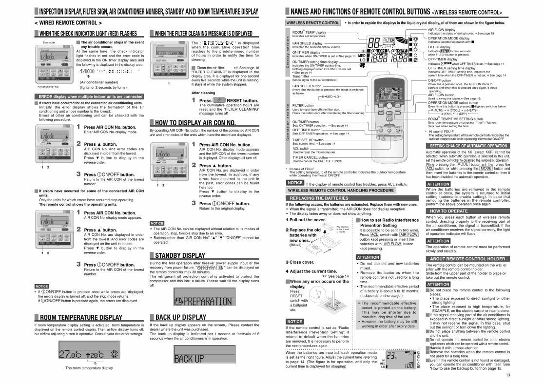
WHEN THE CHECK INDICATOR LIGHT (RED) FLASHES
INSPECTION DISPLAY, FILTER SIGN, AIR CONDITIONER NUMBER, STANDBY AND ROOM TEMPERATURE DISPLAY< WIRED REMOTE CONTROL >
The air conditioner stops in the event
any trouble occurs.
At the same time, the check indicator
light flashes in red and the error code is
displayed in the ON timer display area and
the following is displayed in the display area.
“ ” ⇔ “ ”
(Air conditioner number)
(lights for 2 seconds by turns)
Error code
Air conditioner No.
1 Press AIR CON No. button.Enter AIR CON No. display mode.
2 Press button.AIR CON No. and error codes are
displayed in order from the lowest.
Press button to display in the
reverse order.
3 Press button.Return to the AIR CON of the lowest
number.
1 2
ERROR display when multiple indoor units are connected
If errors have occurred for all the connected air conditioning units.Initially, the error display shows the formation of the air conditioning unit whose number is the lowest.Errors of other air conditioning unit can be checked with the following procedure.
1 Press AIR CON No. button.AIR CON No. display mode appears.
2 Press button.AIR CON No. are displayed in order
from the lowest. And error codes are
displayed on the unit in trouble.
Press button to display in the
reverse order.
3 Press button.Return to the AIR CON of the lowest
number.
If errors have occurred for some of the connected AIR CON
units.
Only the units for which errors have occurred stop operating.
The remote control shows the operating units.
NOTICE
• If button is pressed once while errors are displayed,
the errors display is turned off, and the stop mode returns.
If button is pressed again, the errors are displayed.
HOW TO DISPLAY AIR CON NO.By operating AIR CON No. button, the number of the connected AIR CON
unit and error codes of the units which have the record are displayed.
1 Press AIR CON No. button.AIR CON No. display mode appears and the AIR CON of the lowest number is displayed. Other displays all turn off.
2 Press button.AIR CON No. are displayed in order from the lowest. In addition, if any errors have occurred to the unit in the past, error codes can be found here too.Press button to display in the reverse order.
3 Press button.Return to the original display.
1 2
NOTICE
• The AIR CON No. can be displayed without relation to its modes of
operation, stop, forcible stop due to an error.
• Buttons other than “AIR CON No.” “ ” “ ” “ON/OFF” cannot be
operated.
1 2 STANDBY DISPLAYDuring the fi rst operation after breaker power supply input or the
recovery from power failure, “ ” can be displayed on
the remote control for max 30 minutes.
The refrigerant oil protection control is activated to protect the
compressor and this isn’t a failure. Please wait till the display turns
off.
WHEN THE FILTER CLEANING MESSAGE IS DISPLAYEDThe “ ” is displayed when the cumulative operation time reaches to the predetermined number of hours in order to notify the time for cleaning.
Clean the air fi lter. ☞ See page 16“FILTER CLEANING” is displayed in the display area. It is displayed for one second every fi ve seconds while the unit is running. It stays lit while the system stopped.
After cleaning
1 Press RESET button.The cumulative operation hours are reset and the “FILTER CLEANING” message turns off.
1
ROOM TEMPERATURE DISPLAYIf room temperature display setting is activated, room temperature is
displayed on the remote control display. Then airfl ow display turns off,
but airfl ow adjusting button is operative. Consult your dealer for settings.
The room temperature display
WIRELESS REMOTE CONTROL • In order to explain the displays in the liquid crystal display, all of them are shown in the fi gure below.
AIR FLOW displayIndicates the status of swing louver. ☞See page 15
OPERATION MODE displayIndicates selected operation with .
ON TIMER setting time displayIndicates the ON-TIMER setting time.Nothing displayed when ON-TIMER is not set. ☞See page 14
FAN SPEED button Every time this button is pressed, the mode is switched as below.
HI MED LO
ON-TIMER displayIndicates when ON-TIMER is set. ☞See page 14
FILTER displayIndicates for two seconds when FILTER button is pressed.
OFF-TIMER displayIndicates when OFF-TIMER is set. ☞See page 14
FAN SPEED displayIndicates the selected airflow volume
FILTER button
AIR FLOW buttonUsed to swing the louver. ☞See page 15
ON/OFF buttonWhen this is pressed once, the AIR CON starts to operate and when this is pressed once again, it stops operating.
TransmitterSends signal to the air conditioner.
OFF-TIMER setting time displayIndicates OFF-TIMER setting time. Indicates the current time when the OFF-TIMER is not set. ☞See page 14
Used to reset (turn off) the filter sign.Press the button only after completing the filter cleaning.
Op
era
tio
n s
ec
tio
nD
isp
lay
se
cti
on
ROOM*TEMP display Indicates set temperature.
TIME SET UP switchSets current time. ☞See page 14
ON TIMER buttonSets ON TIMER operation. ☞See page 14
OFF TIMER buttonSets OFF TIMER operation. ☞See page 14
ROOM* TEMP/TIME SETTING buttonSets room temperature by pressing or button.Sets time when setting the time.
ACL switchUsed to reset the microcomputer.
TIMER CANCEL buttonUsed to cancel the TIMER SETTINGS.
OPERATION MODE select buttonEvery time this button is pressed, displays switch as below
(AUTO) (COOL) (HEAT) (FAN) (DRY)
When you press each button of wireless remote control, directing properly to the receiving part of the air conditioner, the signal is transmitted. If the air conditioner receives the signal correctly, the light of operation indicator will fl ash.
ATTENTION
The operation of remote control must be performed slowly and steadily.
HOW TO OPERATE
ABOUT REMOTE CONTROL HOLDER
The remote control can be mounted on the wall or pillar with the remote control holder.Slide from the upper part of the holder to place or take out the remote control.
ATTENTION
Do not place the remote control to the following places.• The place exposed to direct sunlight or other
strong lighting.• The place exposed to high temperature, for
EXAMPLE, on the electric carpet or near a stove.If the signal receiving part of the air conditioner is exposed to direct sunlight or other strong lighting, it may not receive the signal. In this case, shut out the sunlight or turn down the lighting.Do not place anything between the remote control and the unit.Do not operate the remote control for other electric appliances which can be operated with a remote control.Handle it with utmost attention.Remove the batteries when the remote control is not used for a long time.Even if the remote control is not found or damaged, you can operate the air conditioner with itself. See “How to use the backup button” on page 15.
NOTICE If the display of remote control has troubles, press ACL switch.
WIRELESS REMOTE CONTROL HANDLING PROCEDURE
REPLACING THE BATTERIES
1 Pull out the cover.
2 Replace the old
batteries with
new ones. (R03×2)
3 Close cover.
4 Adjust the current time. ☞ See page 14
When any error occurs on the
display, Press
RESET
switch with
a ballpoint
etc.
NOTICE
If the remote control is set as “Radio
Interference Prevention Setting”, it
returns to default when the batteries
are removed. It is necessary to perform
the next procedures again.
If the following occurs, the batteries are exhausted. Replace them with new ones.
• When the signal is transmitted, the AIR CON does not display reception.
• The display fades away or does not show anything.
How to set Radio Interference
Prevention SettingIt is possible to be sent in two ways.
Press ACL switch with AIR FLOW
button kept pressing or insert the
batteries with AIR FLOW button
kept pressing.
ATTENTION
• Do not use old and new batteries
mixed.
• Remove the batteries when the
remote control is not used for a long
time.
• The recommendable effective period
of a battery is about 6 to 12 months.
(It depends on the usage.)
When the batteries are inserted, each operation mode
is set as the right fi gure. Adjust the current time referring
to page 14. (The fi gure is for operation, and only the
current time is displayed for stopping)
Pay attention to the and marks
• The recommendable effective
period is printed on the battery.
This may be shor ter due to
manufacturing time of the unit.
• However the battery may be still
working in order after expiry date.
NAMES AND FUNCTIONS OF REMOTE CONTROL BUTTONS <WIRELESS REMOTE CONTROL>
BACK UP DISPLAYIf the back up display appears on the screen,. Please contact the
dealer where the unit was purchased.
The back up display is indicated per 1 second at intervals of 5
seconds when the air conditioners is in operation.
Automatic operation of the KX (except KXR) cannot be selected. When automatic operation is selected in this unit, set the remote controller to disabled the automatic operation.While pressing the MODE button ant then press the ACL switch, or while pressing the MODE button and then insert the batteries to the remote controller, then it has been disabled the automatic operation.
ATTENTION
When the batteries are removed in the remote controller once, the system is returned to initial setting (automatic enable setting). In case that removing the batteries in the remote controller, perform the above operation once again.
SETTING CHANGE OF AUTOMATIC OPERATION
* IN case of FDU-FThe setting temperature of the remote controller indicates the outdoor temperature while operating thermostat ON/OFF.
* IN case of FDU-FThe setting temperature of the remote controller indicates the outdoor temperature while operating thermostat ON/OFF.
PSA012B820B_EN.indd 13PSA012B820B_EN.indd 13 2016/08/19 13:36:122016/08/19 13:36:12
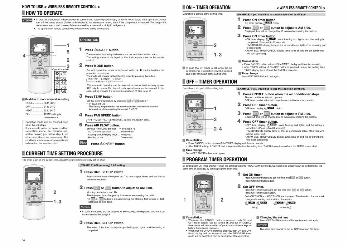
14
ON – TIMER OPERATION < WIRELESS REMOTE CONTROL >
1 Press ON timer button.ON timer display blinks.
2 Press or button to adjust to AM 8:00.Displayed time will be changed by 10 minutes by pressing the buttons.
3 Press ON timer button.• ON timer display stops fl ashing and lights, and the setting is
completed. (Press within 60 seconds)TIMER/CHECK display lamp of the air conditioner lights. (The receiving part of indoor unit)
• At AM 8:00, TIMER/CHECK display lamp turns off and the air conditioner
will start operating.1·3
2
Operation is started at the setting time.
In case the ON timer is set while the air
conditioner is in operation, it will be stopped
and ready for restart at the setting time.
[EXAMPLE] If you would like to start the operation at AM 8:00
Cancellation• Whenever the CANCEL button is pressed, both ON and
OFF timer display will be turned off and the PROGRAM timer mode will be cancelled. (Operation condition is kept as before the button is pressed.)
• Whenever the ON/OFF button is pressed, both ON and OFF timer display will be turned off and the PROGRAM timer mode will be cancelled. The air conditioner stops operating.
Changing the set timePress OFF TIMER button or ON timer button to set again.
NOTICE
The same time cannot be set for OFF timer and ON timer.
PROGRAM TIMER OPERATIONBy setting both ON timer and OFF timer, the settings turn into PROGRAM timer mode. Operation and stopping can be performed at the
same time of each day by setting program timer once.
1 Set ON timer.Press ON timer button and set the time with or button.
Press ON timer button again.
2 Set OFF timer.Press OFF timer button and set the time with or button.
Press OFF timer button again.
Both ON TIMER and OFF TIMER are displayed. The direction of arrow mark
changes depending on the status of operation.
(stop) (operating)
21
OFF – TIMER OPERATION
2·4
3
1
Operation is stopped at the setting time. [EXAMPLE] If you would like to stop the operation at PM 9:00
Cancellation• Press CANCEL button to turn off the TIMER display and timer is canceled.
• After TIMER setting, if ON/OFF button is pressed before the setting time, TIMER display turns off and the TIMER is canceled.
Time changePress OFF TIMER button to set again.
Cancellation • Press CANCEL button to turn off the TIMER display and timer is canceled.
• After TIMER setting, if ON/OFF button is pressed before the setting time,
TIMER display turns off and the TIMER is canceled.
Time changePress ON TIMER button to set again.
HOW TO OPERATE• In order to protect both indoor/outdoor air conditioners, keep the power supply on for six hours before initial operation. Do not
turn off the power supply. (Power is distributed to the crankcase heater, even if the compressor is stopped. This keeps the
compressor warm, and prevents failures caused by accumulation of liquid refrigerant.)
• The operation of remote control must be performed slowly and steadily.
HOW TO USE < WIRELESS REMOTE CONTROL >
ATTENTION
4
15
32
AUTOCOOLHEATDRYFAN
Guideline of room temperature setting
COOL ...............26 to 28°C
DRY ..................21 to 24°C
HEAT ................22 to 24°C
FAN ................... TEMP setting is
unnecessary
• Operation mode can be changed even
when the unit stops.
• If you operate under the same condition
(operation mode, set temperature,
airflow, louver) just follow step 1, no
other operations are necessary. The
conditions which were set previously are
indicated on the remote control
CURRENT TIME SETTING PROCEDURE
1 Press TIME SET UP switch.
Press it with the tip of ballpoint etc. The time display blinks and can be set
to the current time.
2 Press or button to adjust to AM 8:00.
Morning : AM After noon : PM
The displayed time changes by 1 minute when pressing the button.
• If or button is pressed during the blinking, fast-forward or fast-
backward can be done.
NOTICE
• In case the buttons are not pressed for 60 seconds, the displayed time is set as
current time without step 3.
3 Press TIME SET UP switch.
The value of the time displayed stops fl ashing and lights, and the setting is
completed.
1·3
2
The timer is set on the current time. Adjust the current time correctly at fi rst of all.
[EXAMPLE] AM (morning) 8:00 setting
OPERATION
1 Press button.
The operation display light (Green) turns on, and the operation starts.
The setting status is displayed on the liquid crystal area on the remote
control.
2 Press MODE button.
Current operation mode is indicated with the marks besides the
operation mode icons.
The mode will change in the following order by pressing the button.
(AUTO)* (COOL) (HEAT) (FAN) (DRY)
(The automatic operation can be selected in case of heat recovery system
KXR only. In case of KX, the automatic operation cannot be selected. In this
case, setting changes it to automatic operation.) See page 13
3 Press TEMP button.
Set the room temperature by pressing or button.** IN case of FDU-F
The setting temperature of the remote controller indicates the outdoor temperature while operating thermostat ON/OFF.
4 Press FAN SPEED button.
HI MED LO— FAN SPEED can be changed in order.
5 Press AIR FLOW button.Effective AIR FLOW direction ☞ see page 15
AUTO mode operation ............ Intermediate
Cooling, dehumidifying mode ... Horizontal
Heating mode ......................... Downwards
Stop Press button
Operation mode
1 Press ON/OFF button when the air conditioner stops.The air conditioner starts to operate.
OFF timer can be set only in case the air conditioner is in operation.
2 Press OFF timer button.OFF timer display blinks.
3 Press or button to adjust to PM 9:00.Displayed time will be changed by 10 minutes by pressing the buttons.
4 Press OFF timer button.• OFF timer display stops fl ashing and lights, and the setting is
completed. (Press within 60 seconds)
TIMER/CHECK display lamp of the air conditioner lights. (The receiving
part of indoor unit)
• At PM 9:00, TIMER/CHECK display lamp turns off and the air conditioner will stops operating.
PSA012B820B_EN.indd 14PSA012B820B_EN.indd 14 2016/08/19 13:36:152016/08/19 13:36:15
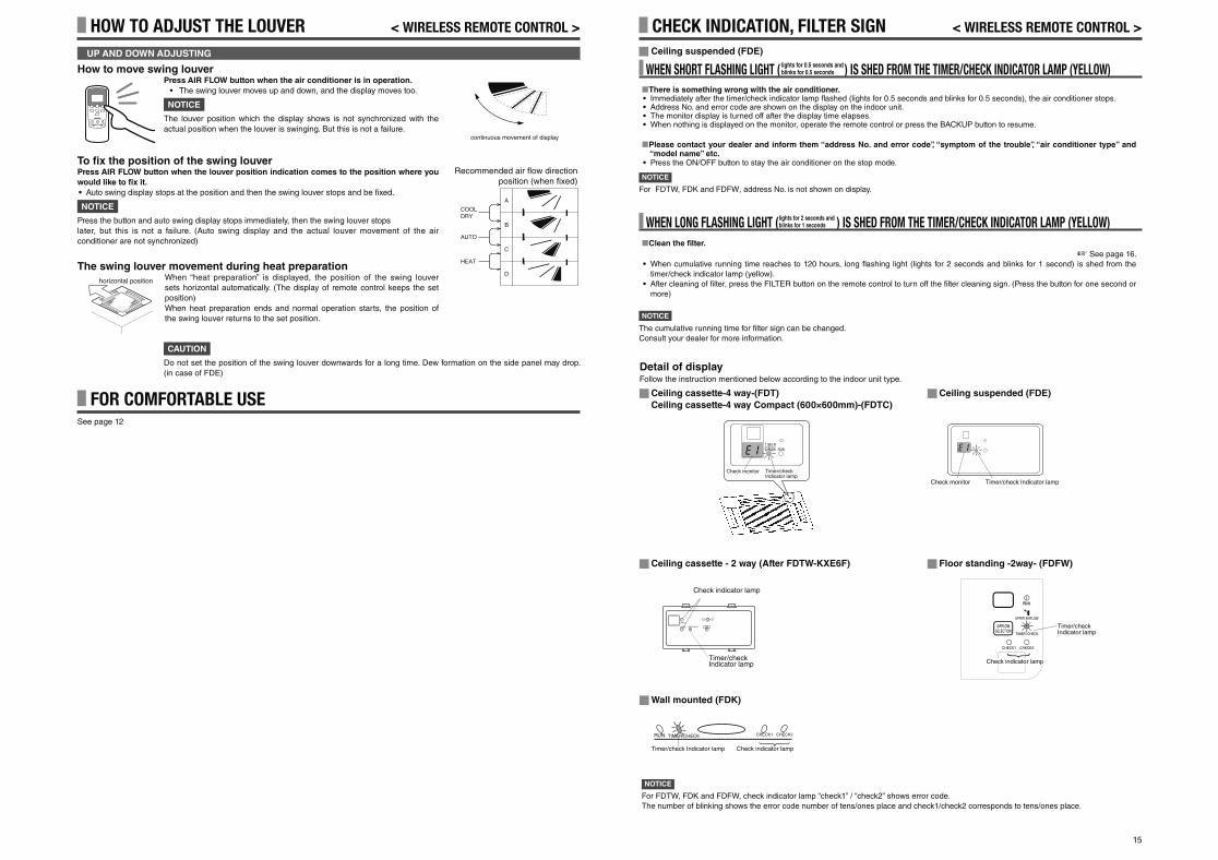
15
To fi x the position of the swing louverPress AIR FLOW button when the louver position indication comes to the position where you
would like to fi x it.
• Auto swing display stops at the position and then the swing louver stops and be fi xed.
NOTICE
Press the button and auto swing display stops immediately, then the swing louver stops
later, but this is not a failure. (Auto swing display and the actual louver movement of the air
conditioner are not synchronized)
The swing louver movement during heat preparationWhen “heat preparation” is displayed, the position of the swing louver
sets horizontal automatically. (The display of remote control keeps the set
position)
When heat preparation ends and normal operation starts, the position of
the swing louver returns to the set position.
Recommended air flow directionposition (when fixed)
A
B
C
D
COOLDRY
AUTO
HEAT
How to move swing louverPress AIR FLOW button when the air conditioner is in operation.
• The swing louver moves up and down, and the display moves too.
NOTICE
The louver position which the display shows is not synchronized with the
actual position when the louver is swinging. But this is not a failure.
UP AND DOWN ADJUSTING
continuous movement of display
HOW TO ADJUST THE LOUVER < WIRELESS REMOTE CONTROL >
horizontal position
FOR COMFORTABLE USESee page 12
CAUTION
Do not set the position of the swing louver downwards for a long time. Dew formation on the side panel may drop.
(in case of FDE)
CHECK INDICATION, FILTER SIGN < WIRELESS REMOTE CONTROL >
Ceiling suspended (FDE)
WHEN SHORT FLASHING LIGHT ( ) IS SHED FROM THE TIMER/CHECK INDICATOR LAMP (YELLOW)There is something wrong with the air conditioner.
• Immediately after the timer/check indicator lamp fl ashed (lights for 0.5 seconds and blinks for 0.5 seconds), the air conditioner stops.• Address No. and error code are shown on the display on the indoor unit.• The monitor display is turned off after the display time elapses.• When nothing is displayed on the monitor, operate the remote control or press the BACKUP button to resume.
Please contact your dealer and inform them “address No. and error code”, “symptom of the trouble”, “air conditioner type” and “model name” etc.
• Press the ON/OFF button to stay the air conditioner on the stop mode.
lights for 0.5 seconds and blinks for 0.5 seconds
WHEN LONG FLASHING LIGHT ( ) IS SHED FROM THE TIMER/CHECK INDICATOR LAMP (YELLOW)Clean the fi lter.
☞ See page 16.
• When cumulative running time reaches to 120 hours, long fl ashing light (lights for 2 seconds and blinks for 1 second) is shed from the
timer/check indicator lamp (yellow).
• After cleaning of fi lter, press the FILTER button on the remote control to turn off the fi lter cleaning sign. (Press the button for one second or
more)
lights for 2 seconds and blinks for 1 seconds
NOTICE
The cumulative running time for fi lter sign can be changed.
Consult your dealer for more information.
NOTICE
For FDTW, FDK and FDFW, address No. is not shown on display.
NOTICE
For FDTW, FDK and FDFW, check indicator lamp “check1” / “check2” shows error code.
The number of blinking shows the error code number of tens/ones place and check1/check2 corresponds to tens/ones place.
Detail of displayFollow the instruction mentioned below according to the indoor unit type.
Ceiling cassette-4 way-(FDT)
Ceiling cassette-4 way Compact (600×600mm)-(FDTC)
TIMERCHECK RUN
Ceiling suspended (FDE)
Ceiling cassette - 2 way (After FDTW-KXE6F) Floor standing -2way- (FDFW)
Check monitor Timer/check Indicator lamp
Check monitor Timer/check Indicator lamp
Check indicator lamp
Timer/check Indicator lamp
Wall mounted (FDK)
RUN TIMER/CHECK CHECK1 CHECK2
Check indicator lampTimer/check Indicator lamp
CHECK1
CHECK2 TIMER/CHECK RUN
点検LEDCheck indicator lamp
Timer/check Indicator lamp
PSA012B820B_EN.indd 15PSA012B820B_EN.indd 15 2016/08/19 13:36:172016/08/19 13:36:17
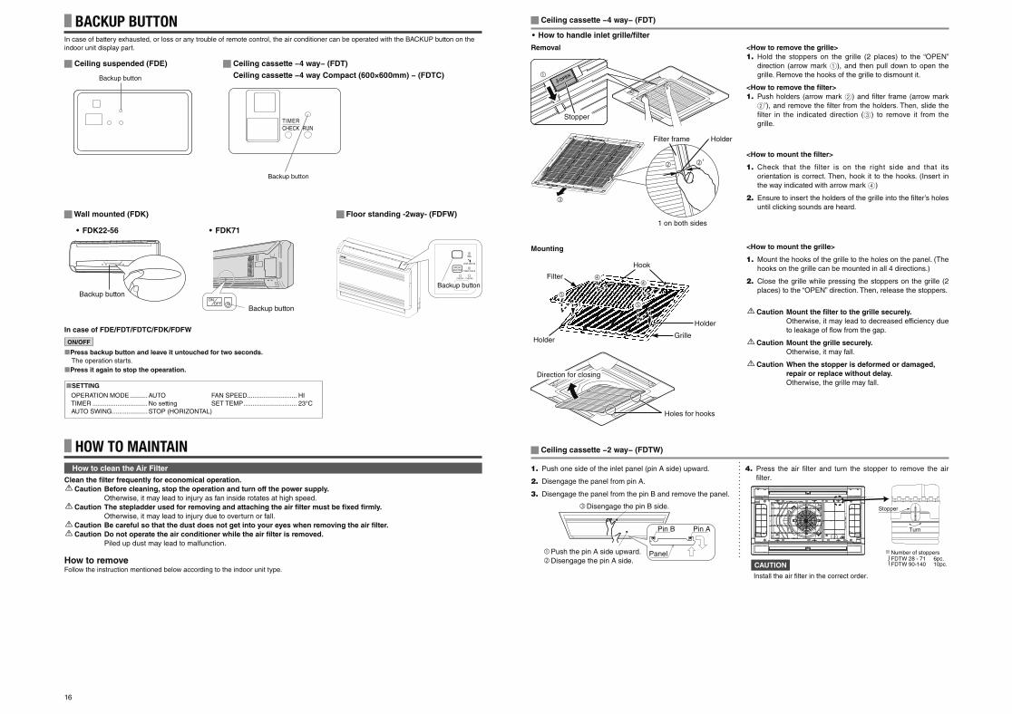
16
HOW TO MAINTAINHow to clean the Air Filter
Clean the fi lter frequently for economical operation.
Caution Before cleaning, stop the operation and turn off the power supply.
Otherwise, it may lead to injury as fan inside rotates at high speed.
Caution The stepladder used for removing and attaching the air fi lter must be fi xed fi rmly.
Otherwise, it may lead to injury due to overturn or fall.
Caution Be careful so that the dust does not get into your eyes when removing the air fi lter.
Caution Do not operate the air conditioner while the air fi lter is removed.
Piled up dust may lead to malfunction.
How to removeFollow the instruction mentioned below according to the indoor unit type.
Ceiling cassette −4 way− (FDT)
<How to remove the grille>
1. Hold the stoppers on the grille (2 places) to the “OPEN”
direction (arrow mark 1), and then pull down to open the
grille. Remove the hooks of the grille to dismount it.
<How to remove the fi lter>
1. Push holders (arrow mark 2) and fi lter frame (arrow mark
2’), and remove the fi lter from the holders. Then, slide the
fi lter in the indicated direction (3) to remove it from the
grille.
<How to mount the fi lter>
1. Check that the filter is on the right side and that its
orientation is correct. Then, hook it to the hooks. (Insert in
the way indicated with arrow mark 4)
2. Ensure to insert the holders of the grille into the fi lter’s holes
until clicking sounds are heard.
<How to mount the grille>
1. Mount the hooks of the grille to the holes on the panel. (The
hooks on the grille can be mounted in all 4 directions.)
2. Close the grille while pressing the stoppers on the grille (2
places) to the “OPEN” direction. Then, release the stoppers.
Caution Mount the fi lter to the grille securely.
Otherwise, it may lead to decreased efficiency due
to leakage of fl ow from the gap.
Caution Mount the grille securely.
Otherwise, it may fall.
Caution When the stopper is deformed or damaged,
repair or replace without delay.
Otherwise, the grille may fall.
• How to handle inlet grille/fi lter
Removal
BACKUP BUTTONIn case of battery exhausted, or loss or any trouble of remote control, the air conditioner can be operated with the BACKUP button on the
indoor unit display part.
TIMERCHECK RUN
Backup button
Ceiling cassette −4 way− (FDT)
Backup button
Ceiling suspended (FDE)
Ceiling cassette −4 way Compact (600×600mm) − (FDTC)
ON/OFF
Press backup button and leave it untouched for two seconds.
The operation starts.
Press it again to stop the opearation.
OPERATION MODE .......... AUTO FAN SPEED ............................ HI
TIMER ............................... No setting SET TEMP .............................. 23°C
AUTO SWING .................... STOP (HORIZONTAL)
SETTING
In case of FDE/FDT/FDTC/FDK/FDFW
Wall mounted (FDK)
Backup button
• FDK22-56
ONOFF
Backup button
• FDK71
Floor standing -2way- (FDFW)
Backup button
Ceiling cassette −2 way− (FDTW)
1. Push one side of the inlet panel (pin A side) upward.
2. Disengage the panel from pin A.
3. Disengage the panel from the pin B and remove the panel.
4. Press the air filter and turn the stopper to remove the air filter.
Disengage the pin B side.
Push the pin A side upward. Disengage the pin A side.
Pin B Pin A
Panel
Stopper
Number of stoppersFDTW 28 - 71 6pc.FDTW 90-140 10pc.
Install the air filter in the correct order.
Turn
CAUTION
Mounting
Stopper
�
Holder
GrilleHolder
Hook
Filter
′′
HolderFilter frame
1 on both sides
Holes for hooks
Direction for closing
PSA012B792B_C_EN.indd 16PSA012B792B_C_EN.indd 16 2016/08/19 14:14:352016/08/19 14:14:35
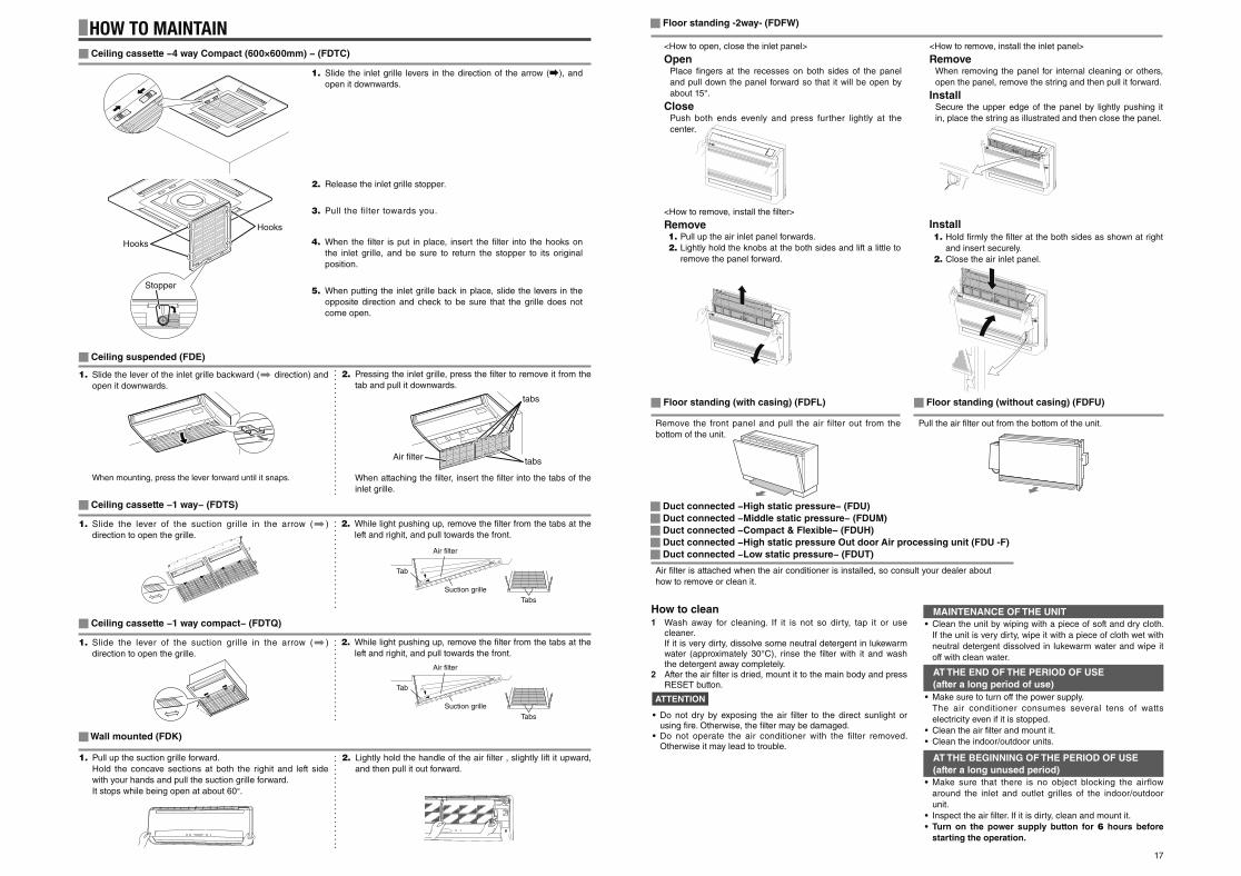
17
HOW TO MAINTAIN
When mounting, press the lever forward until it snaps. When attaching the fi lter, insert the fi lter into the tabs of the
inlet grille.
Ceiling suspended (FDE)
1. Slide the lever of the inlet grille backward ( direction) and
open it downwards.
2. Pressing the inlet grille, press the fi lter to remove it from the
tab and pull it downwards.
Air fi lter is attached when the air conditioner is installed, so consult your dealer about
how to remove or clean it.
MAINTENANCE OF THE UNIT
AT THE END OF THE PERIOD OF USE
(after a long period of use)
AT THE BEGINNING OF THE PERIOD OF USE
(after a long unused period)
• Clean the unit by wiping with a piece of soft and dry cloth.
If the unit is very dirty, wipe it with a piece of cloth wet with
neutral detergent dissolved in lukewarm water and wipe it
off with clean water.
• Make sure to turn off the power supply.
The air conditioner consumes several tens of watts
electricity even if it is stopped.
• Clean the air fi lter and mount it.
• Clean the indoor/outdoor units.
• Make sure that there is no object blocking the airflow
around the inlet and outlet grilles of the indoor/outdoor
unit.
• Inspect the air fi lter. If it is dirty, clean and mount it.
• Turn on the power supply button for 6 hours before
starting the operation.
How to clean1 Wash away for cleaning. If it is not so dirty, tap it or use
cleaner. If it is very dirty, dissolve some neutral detergent in lukewarm
water (approximately 30°C), rinse the fi lter with it and wash the detergent away completely.
2 After the air fi lter is dried, mount it to the main body and press RESET button.
ATTENTION
• Do not dry by exposing the air fi lter to the direct sunlight or using fi re. Otherwise, the fi lter may be damaged.
• Do not operate the air conditioner with the filter removed. Otherwise it may lead to trouble.
Ceiling cassette −4 way Compact (600×600mm) − (FDTC)
1. Slide the inlet grille levers in the direction of the arrow ( ), and
open it downwards.
2. Release the inlet grille stopper.
3. Pull the filter towards you.
4. When the fi lter is put in place, insert the fi lter into the hooks on
the inlet grille, and be sure to return the stopper to its original
position.
5. When putting the inlet grille back in place, slide the levers in the
opposite direction and check to be sure that the grille does not
come open.
Hooks
Stopper
Hooks
Ceiling cassette −1 way− (FDTS)
1. Slide the lever of the suction grille in the arrow ( )
direction to open the grille.
2. While light pushing up, remove the fi lter from the tabs at the
left and righit, and pull towards the front.
Ceiling cassette −1 way compact− (FDTQ)
1. Slide the lever of the suction grille in the arrow ( )
direction to open the grille.
2. While light pushing up, remove the fi lter from the tabs at the
left and righit, and pull towards the front.
Air fi lter
Tab
Suction grille
Tabs
Air fi lter
Tab
Suction grille
Tabs
Wall mounted (FDK)
1. Pull up the suction grille forward.
Hold the concave sections at both the righit and left side
with your hands and pull the suction grille forward.
It stops while being open at about 60°.
2. Lightly hold the handle of the air filter , slightly lift it upward,
and then pull it out forward.
Duct connected −High static pressure− (FDU)
Duct connected −Middle static pressure− (FDUM)
Duct connected −Compact & Flexible− (FDUH)
Duct connected −High static pressure Out door Air processing unit (FDU -F)
Duct connected −Low static pressure− (FDUT)
Floor standing -2way- (FDFW)
<How to open, close the inlet panel>
OpenPlace fi ngers at the recesses on both sides of the panel
and pull down the panel forward so that it will be open by
about 15°.
ClosePush both ends evenly and press further lightly at the
center.
<How to remove, install the inlet panel>
RemoveWhen removing the panel for internal cleaning or others,
open the panel, remove the string and then pull it forward.
InstallSecure the upper edge of the panel by lightly pushing it
in, place the string as illustrated and then close the panel.
<How to remove, install the fi lter>
Remove1. Pull up the air inlet panel forwards.
2. Lightly hold the knobs at the both sides and lift a little to
remove the panel forward.
Install1. Hold firmly the filter at the both sides as shown at right
and insert securely.
2. Close the air inlet panel.
Floor standing (with casing) (FDFL)
Remove the front panel and pull the air filter out from the
bottom of the unit.
Floor standing (without casing) (FDFU)
Pull the air filter out from the bottom of the unit.
Air filter
tabs
tabs
PSA012B820B_EN.indd 17PSA012B820B_EN.indd 17 2016/08/19 13:36:182016/08/19 13:36:18
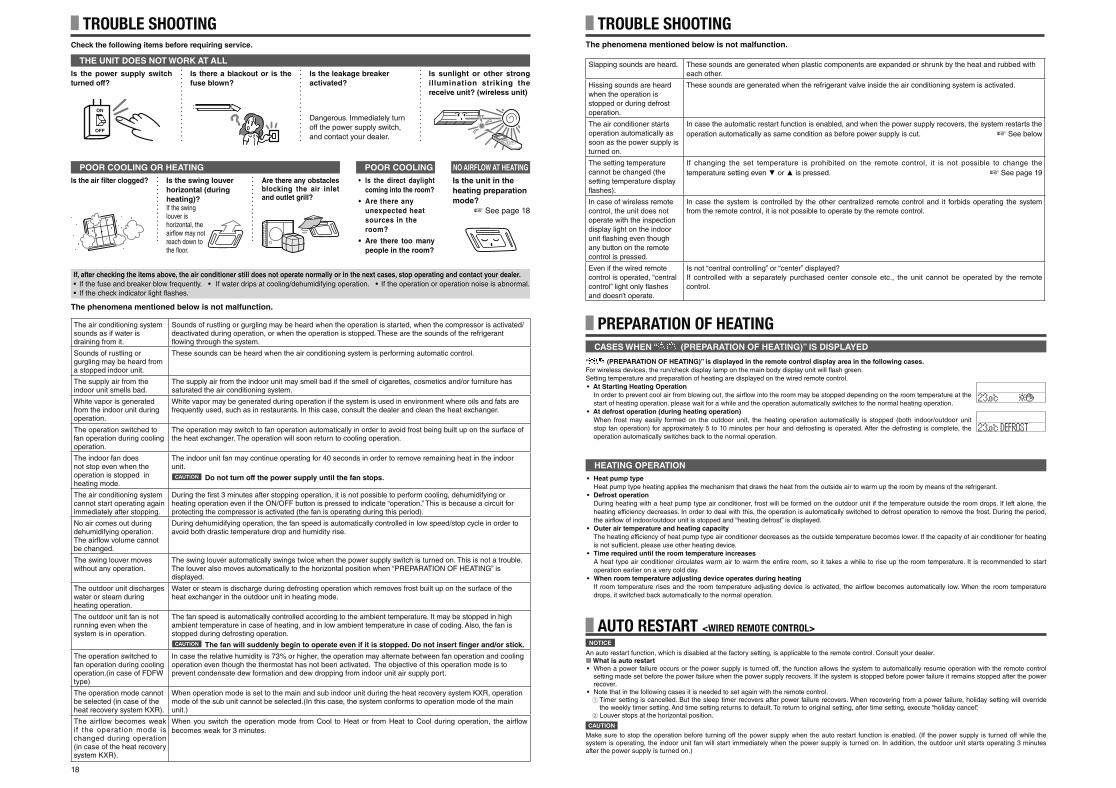
18
HEATING OPERATION
PREPARATION OF HEATING
• Heat pump type
Heat pump type heating applies the mechanism that draws the heat from the outside air to warm up the room by means of the refrigerant.
• Defrost operation
During heating with a heat pump type air conditioner, frost will be formed on the outdoor unit if the temperature outside the room drops. If left alone, the
heating efficiency decreases. In order to deal with this, the operation is automatically switched to defrost operation to remove the frost. During the period,
the airfl ow of indoor/outdoor unit is stopped and “heating defrost” is displayed.
• Outer air temperature and heating capacity
The heating efficiency of heat pump type air conditioner decreases as the outside temperature becomes lower. If the capacity of air conditioner for heating
is not sufficient, please use other heating device.
• Time required until the room temperature increases
A heat type air conditioner circulates warm air to warm the entire room, so it takes a while to rise up the room temperature. It is recommended to start
operation earlier on a very cold day.
• When room temperature adjusting device operates during heating
If room temperature rises and the room temperature adjusting device is activated, the airfl ow becomes automatically low. When the room temperature
drops, it switched back automatically to the normal operation.
“ (PREPARATION OF HEATING)” is displayed in the remote control display area in the following cases.
For wireless devices, the run/check display lamp on the main body display unit will fl ash green.
Setting temperature and preparation of heating are displayed on the wired remote control.
• At Starting Heating Operation
In order to prevent cool air from blowing out, the airfl ow into the room may be stopped depending on the room temperature at the
start of heating operation. please wait for a while and the operation automatically switches to the normal heating operation.
• At defrost operation (during heating operation)
When frost may easily formed on the outdoor unit, the heating operation automatically is stopped (both indoor/outdoor unit
stop fan operation) for approximately 5 to 10 minutes per hour and defrosting is operated. After the defrosting is complete, the
operation automatically switches back to the normal operation.
CASES WHEN “ (PREPARATION OF HEATING)” IS DISPLAYED
NOTICE
An auto restart function, which is disabled at the factory setting, is applicable to the remote control. Consult your dealer. What is auto restart
• When a power failure occurs or the power supply is turned off, the function allows the system to automatically resume operation with the remote control setting made set before the power failure when the power supply recovers. If the system is stopped before power failure it remains stopped after the power recover.
• Note that in the following cases it is needed to set again with the remote control.1 Timer setting is cancelled. But the sleep timer recovers after power failure recovers. When recovering from a power failure, holiday setting will override
the weekly timer setting. And time setting returns to default. To return to original setting, after time setting, execute “holiday cancel”.2 Louver stops at the horizontal position.
CAUTION
Make sure to stop the operation before turning off the power supply when the auto restart function is enabled. (If the power supply is turned off while the system is operating, the indoor unit fan will start immediately when the power supply is turned on. In addition, the outdoor unit starts operating 3 minutes after the power supply is turned on.)
AUTO RESTART <WIRED REMOTE CONTROL>
TROUBLE SHOOTINGThe phenomena mentioned below is not malfunction.
Slapping sounds are heard. These sounds are generated when plastic components are expanded or shrunk by the heat and rubbed with
each other.
Hissing sounds are heard
when the operation is
stopped or during defrost
operation.
These sounds are generated when the refrigerant valve inside the air conditioning system is activated.
The air conditioner starts
operation automatically as
soon as the power supply is
turned on.
In case the automatic restart function is enabled, and when the power supply recovers, the system restarts the
operation automatically as same condition as before power supply is cut. ☞ See below
The setting temperature
cannot be changed (the
setting temperature display
fl ashes).
If changing the set temperature is prohibited on the remote control, it is not possible to change the
temperature setting even or is pressed. ☞ See page 19
In case of wireless remote
control, the unit does not
operate with the inspection
display light on the indoor
unit fl ashing even though
any button on the remote
control is pressed.
In case the system is controlled by the other centralized remote control and it forbids operating the system
from the remote control, it is not possible to operate by the remote control.
Even if the wired remote
control is operated, “central
control” light only fl ashes
and doesn’t operate.
Is not “central controlling” or “center” displayed?
If controlled with a separately purchased center console etc., the unit cannot be operated by the remote
control.
TROUBLE SHOOTINGCheck the following items before requiring service.
THE UNIT DOES NOT WORK AT ALL
Is the power supply switch
turned off?
Is there a blackout or is the
fuse blown?
Is the leakage breaker
activated?
Dangerous. Immediately turn
off the power supply switch,
and contact your dealer.
Is sunlight or other strong
illumination striking the
receive unit? (wireless unit)
ON
OFF
Is the air fi lter clogged? Is the swing louver
horizontal (during
heating)?If the swing louver is horizontal, the airfl ow may not reach down to the fl oor.
Are there any obstacles blocking the air inlet and outlet grill?
• Is the direct daylight
coming into the room?
• Are there any
unexpected heat
sources in the
room?
• Are there too many
people in the room?
Is the unit in the
heating preparation
mode?
☞ See page 18
POOR COOLING OR HEATING POOR COOLING
If, after checking the items above, the air conditioner still does not operate normally or in the next cases, stop operating and contact your dealer.
• If the fuse and breaker blow frequently. • If water drips at cooling/dehumidifying operation. • If the operation or operation noise is abnormal.
• If the check indicator light fl ashes.
The phenomena mentioned below is not malfunction.
NO AIRFLOW AT HEATING
The air conditioning system sounds as if water is draining from it.
Sounds of rustling or gurgling may be heard when the operation is started, when the compressor is activated/deactivated during operation, or when the operation is stopped. These are the sounds of the refrigerant fl owing through the system.
Sounds of rustling or gurgling may be heard from a stopped indoor unit.
These sounds can be heard when the air conditioning system is performing automatic control.
The supply air from the indoor unit smells bad.
The supply air from the indoor unit may smell bad if the smell of cigarettes, cosmetics and/or furniture has saturated the air conditioning system.
White vapor is generated from the indoor unit during operation.
White vapor may be generated during operation if the system is used in environment where oils and fats are frequently used, such as in restaurants. In this case, consult the dealer and clean the heat exchanger.
The operation switched to fan operation during cooling operation.
The operation may switch to fan operation automatically in order to avoid frost being built up on the surface of the heat exchanger. The operation will soon return to cooling operation.
The indoor fan does not stop even when the operation is stopped in heating mode.
The indoor unit fan may continue operating for 40 seconds in order to remove remaining heat in the indoor unit.
CAUTION Do not turn off the power supply until the fan stops.
The air conditioning system cannot start operating again immediately after stopping.
During the fi rst 3 minutes after stopping operation, it is not possible to perform cooling, dehumidifying or heating operation even if the ON/OFF button is pressed to indicate “operation.” This is because a circuit for protecting the compressor is activated (the fan is operating during this period).
No air comes out during dehumidifying operation. The airfl ow volume cannot be changed.
During dehumidifying operation, the fan speed is automatically controlled in low speed/stop cycle in order to avoid both drastic temperature drop and humidity rise.
The swing louver moves without any operation.
The swing louver automatically swings twice when the power supply switch is turned on. This is not a trouble. The louver also moves automatically to the horizontal position when “PREPARATION OF HEATING” is displayed.
The outdoor unit discharges water or steam during heating operation.
Water or steam is discharge during defrosting operation which removes frost built up on the surface of the heat exchanger in the outdoor unit in heating mode.
The outdoor unit fan is not running even when the system is in operation.
The fan speed is automatically controlled according to the ambient temperature. It may be stopped in high ambient temperature in case of heating, and in low ambient temperature in case of coding. Also, the fan is stopped during defrosting operation.
CAUTION The fan will suddenly begin to operate even if it is stopped. Do not insert fi nger and/or stick.
The operation switched to fan operation during cooling operation.(in case of FDFW type)
In case the relative humidity is 73% or higher, the operation may alternate between fan operation and cooling operation even though the thermostat has not been activated. The objective of this operation mode is to prevent condensate dew formation and dew dropping from indoor unit air supply port.
The operation mode cannot be selected (in case of the heat recovery system KXR).
When operation mode is set to the main and sub indoor unit during the heat recovery system KXR, operation mode of the sub unit cannot be selected.(In this case, the system conforms to operation mode of the main unit.)
The airflow becomes weak if the operation mode is changed during operation (in case of the heat recovery system KXR).
When you switch the operation mode from Cool to Heat or from Heat to Cool during operation, the airflow
becomes weak for 3 minutes.
PSA012B820B_EN.indd 18PSA012B820B_EN.indd 18 2016/08/19 13:36:192016/08/19 13:36:19
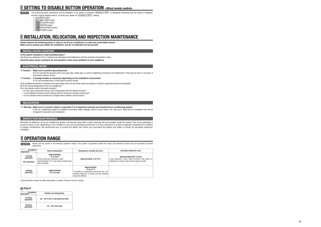
19
The following button operations can be disabled. If the button is pressed, “ ” is displayed indicating that the button is disabled,
and the original display returns. Consult your dealer for “ ” setting.1 button 2 TEMP button
3 LOUVER button
4 MODE button
5 FAN SPEED button
6 TIMER button
SETTING TO DISABLE BUTTON OPERATION <Wired remote control>NOTICE
Please observe the following points in order to use the air conditioner in a safe and comfortable manner.
Make sure to request your dealer for installation, and do not attempt to do by yourself.
Is the system installed in a well-ventilated place?
Are there any obstacles? If so, it leads to the decrease of the efficiency and the increase of operation noise.
Avoid the place where cool/warm air and operation noise cause problems to your neighbors.
INSTALLATION LOCATION
Normally the efficiency of the air conditioning system will become lower after a while, because dirt accumulates inside the system. This occurs gradually in
around 3 years of use, depending on the condition of use and surrounding environment. It is thus necessary to conduct inspection maintenance in addition
to regular maintenance. We recommend you to consult the dealer from whom you purchased the system and make a contract for periodical inspection.
(charged).
INSTALLATION, RELOCATION, AND INSPECTION MAINTENANCE
Warning : Make sure to consult a dealer or specialist if it is required to relocate and reinstall the air conditioning system.
If the air conditioning system is installed incorrectly, water leakage, electric shock and/or fi re may occur. Note that an installation fee will be
charged for relocation and installation.
Caution : Make sure to perform grounding work
Do not connect the ground wire to any gas pipe, water pipe, or wires of lightning conductors and telephones. If the ground work is not good, it
may lead to electric shock.
Caution : A leakage breaker is necessary depending on the installation environment.
If it is not mounted there, it may lead to electric shock.
Only qualifi ed specialists of electrical and grounding work can do these works according to “electric equipment technical standards”.
Is the wiring designated for the air conditioner?
Is the remote control mounted correctly?
• In the case of exposed wiring, is the wiring fi xed with the attached screw?
• Is the attached remote control clamps used for fi xing the remote control cord?
• Is the remote control mounted at a height where children cannot reach?
ELECTRICAL WORK
RELOCATION
INSPECTION MAINTENANCE
Cooling operation
Dry operation
Heating operation
Room temperature
Approximately
21 to 32°C
Long continuous operation under
approximately 21°C may lead to malfunction
due to dewfall
Approximately
27°C or less
Temperature outside the room
Approximately -5 to 43°C
Approximately
-10 to 21°C
If outside air temperature becomes low, the
heating efficiency is lowed and the heating
becomes difficult.
Humidity inside the room
Approximately 80% or less
Long operation under high humidity may leads to
waterdrop or smoky vapor at the supply air grille.
OPERATION RANGEPlease use the system in the following operation range. If the system is operated outside this range, the protection controls may be activated to prevent
malfunction.CAUTION
(Note) Operation range may differ depending on models .Please check the catalog.
ConditionOperation
Cooling operation
Heating operation
Outdoor air temperature
-10 ~ 24°C Dry-bulb
ConditionOperation
20 ~ 40°C (32°C wet-bulb) Dry-bulb
FDU-F
PSA012B820B_EN.indd 19PSA012B820B_EN.indd 19 2016/08/19 13:36:192016/08/19 13:36:19
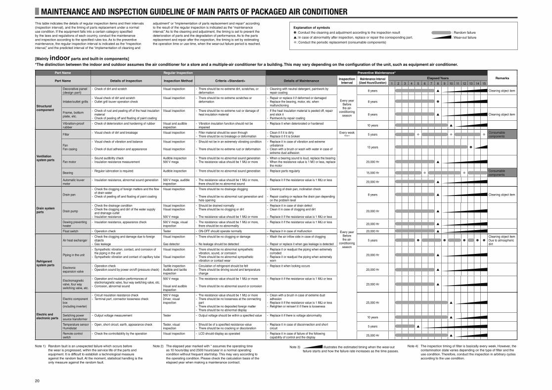
20
MAINTENANCE AND INSPECTION GUIDELINE OF MAIN PARTS OF PACKAGED AIR CONDITIONERThis table indicates the details of regular inspection items and their intervals
(inspection interval), and the timing of parts replacement under a normal
use condition. If the equipment falls into a certain category specifi ed
by the laws and regulations of each country, conduct the maintenance
and inspection according to the specifi ed rules too. As to the preventive
maintenance, the regular inspection interval is indicated as the “inspection
interval,” and the predicted interval of the “implementation of cleaning and
adjustment” or “implementation of parts replacement and repair” according
to the result of the regular inspection is indicated as the “maintenance
interval.” As to the cleaning and adjustment, the timing is set to prevent the
deterioration of parts and the degradation of performance. As to the parts
replacement and repair after the inspection, the timing is set by estimating
the operation time or use time, when the wear-out failure period is reached.
Note 1) Random fault is an unexpected failure which occurs before
the wear is progressed, within the service life of the parts and
equipment. It is difficult to establish a technological measure
against the random fault. At the moment, statistical handling is the
only measure against the random fault.
Note 2) The elapsed year marked with * assumes the operating time
as 10 hours/day and 2500 hours/year in a normal operating
condition without frequent start/stop. This may vary according to
the operating condition. Please check the calculation basis of the
elapsed year when making a maintenance contract.
Note 3) illustrates the estimated timing when the wear-out
failure starts and how the failure rate increases as the time passes.
Note 4) The inspection timing of fi lter is basically every week. However, the
contamination state varies depending on the type of fi lter and the
use condition. Therefore, conduct the inspection in arbitrary cycles
according to the use condition.
[Mainly indoor parts and built-in components]
*The distinction between the indoor and outdoor assumes the air conditioner for a store and a multiple-air conditioner for a building. This may vary depending on the confi guration of the unit, such as equipment air conditioner.
Part Name Regular Inspection Preventive Maintenance*
RemarksPart Name Details of Inspection Inspection Method Criteria <Standard> Details of Maintenance
Inspection Interval
Maintenance Interval(Used Hours/Duration)
Elapsed Years
1 2 3 4 5 6 7 8 9 10 11 12 13 14 15
Structural component
Decorative panel (design part)
- Check of dirt and scratch Visual inspection - There should be no extreme dirt, scratches, or deformation
- Cleaning with neutral detergent, paintwork by repair coating
Every yearBefore the air-
conditioning season
8 years Cleaning object item
Intake/outlet grills- Visual check of dirt and scratch- Outlet grill louver operation check
Visual inspection - There should be no extreme scratches or deformation
- Repair or replace it if deformed or damaged- Replace the bearing, motor, etc. when
malfunctioning8 years
Frame, bottom plate, etc.
- Check of rust and peeling off of the heat insulation material
- Check of peeling off and fl oating of paint coating
Visual inspection - There should be no extreme rust or damage of heat insulation material
- If the heat insulation material is peeled off, repair and stick it
- Paintwork by repair coating8 years Cleaning object item
Vibration-proof rubber
- Check of deterioration and hardening of rubber Visual and audible inspection
- Vibration insulation function should not be impaired
- Replace it when deteriorated or hardened10 years
Ventilation system parts
Filter- Visual check of dirt and breakage Visual inspection - Filter material should be seen through
- There should be no breakage or deformation- Clean it if it is dirty- Replace it if it is broken
Every week Note 4 5 years
Consumable components
FanFan casing
- Visual check of vibration and balance
- Check of dust adhesion and appearance
Visual inspection
Visual inspection
- Should not be in an extremely vibrating condition
- There should be no extreme rust or deformation
- Replace it in case of vibration and extreme unbalance
- Clean with a brush or wash with water in case of extreme dust adhesion
Every yearBefore the air-
conditioning season
13 years
Fan motor- Sound audibility check- Insulation resistance measurement
Audible inspection500 V mega
- There should be no abnormal sound generation- The resistance value should be 1 MΩ or more
- When a bearing sound is loud, replace the bearing- When the resistance value is 1 MΩ or less, replace
the motor20,000 Hr
Bearing- Regular lubrication is required Audible inspection - There should be no abnormal sound generation - Replace parts regularly
15,000 HrConsumable components
Automatic louver motor
- Insulation resistance, abnormal sound generation 500 V mega, audible inspection
- The resistance value should be 1 MΩ or more, there should be no abnormal sound
- Replace it if the resistance value is 1 MΩ or less20,000 Hr
Drain system parts
Drain pan
- Check the clogging of foreign matters and the fl ow of drain water
- Check of peeling off and fl oating of paint coating
Visual inspection - There should be no drainage clogging
- There should be no abnormal rust generation and hole opening
- Cleaning of drain pan, inclination check
- Repair coating or replace the drain pan depending on the problem level
8 years Cleaning object item
Drain pump
- Check the drainage condition- Check the clogging and dirt of the water supply
and drainage outlet- Insulation resistance
Visual inspectionVisual inspection
500 V mega
- Should be drained normally- There should be no clogging or dirt
- The resistance value should be 1 MΩ or more
- Replace it in case of drain defect- Clean it in case of clogging and dirt
- Replace it if the resistance value is 1 MΩ or less
20,000 Hr
Dewing preventing heater
- Insulation resistance, appearance check 500 V mega, visual inspection
- The resistance value should be 1 MΩ or more, there should be no abnormality
- Replace it if the resistance value is 1 MΩ or less20,000 Hr
Float switch - Operation check Tester - ON-OFF should operate normally - Replace it in case of malfunction 20,000 Hr
Refrigerant system parts
Air heat exchanger- Check the clogging and damage due to foreign
objects- Gas leakage
Visual inspection
Gas detector
- There should be no clogging or damage
- No leakage should be detected
- Wash the air infl ow side in case of clogging
- Repair or replace it when gas leakage is detected5 years
Cleaning object itemDue to atmospheric dirt
Piping in the unit
- Sympathetic vibration, contact, and corrosion of the piping in the unit
- Sympathetic vibration and contact of capillary tube
Visual inspection
Visual inspection
- There should be no abnormal sympathetic vibration, sound, or corrosion
- There should be no abnormal sympathetic vibration or contact wear
- Replace it or readjust the piping when extremely corroded
- Replace it or readjust the piping when extremely worn
20,000 Hr
Electronic expansion valve
- Operation check- Operation sound by power on/off (pressure check)
Tactile inspectionAudible and tactile inspection
- Circulation of refrigerant should be felt- There should be driving sound and temperature
change
- Replace it when locking occurs20,000 Hr
Electromagnetic valve, four way switching valve, etc.
- Operation and insulation performances of electromagnetic valve, four way switching valve, etc.
- Corrosion, abnormal sound
500 V mega
Visual and audible inspection
- The resistance value should be 1 MΩ or more
- There should be no abnormal sound or corrosion
- Replace it if the resistance value is 1 MΩ or less
20,000 Hr
Electric and electronic parts
Electric component box(including inverter)
- Circuit insulation resistance check- Terminal part, connector looseness check
500 V megaDriver, visual inspection
- The resistance value should be 1 MΩ or more- There should be no looseness at the connecting
part- There should be no deposited foreign matter- There should be no abnormal display
- Clean with a brush in case of extreme dust adhesion
- Replace it if the resistance value is 1 MΩ or less- Retighten or reinsert it if there is looseness
25,000 Hr
Switching power source transformer
- Output voltage measurement Tester - Output voltage should be within a specifi ed value - Replace it if there is voltage abnormality10 years
Temperature sensorHumidistat
- Open, short circuit, earth, appearance check Tester, visual inspection
- Should be of a specifi ed resistance value- There should be no cracking or discoloration
- Replace it in case of disconnection and short circuit
5 years
Remote control switch
- Check the controllability by the operation Visual inspection - LCD should display as operated - Replace it in case of failure of the following capability of control and the display
25,000 Hr
Explanation of symbols
: Conduct the cleaning and adjustment according to the inspection result
: In case of abnormality after inspection, replace or repair the corresponding part.
: Conduct the periodic replacement (consumable components)
: Random failure
: Wear-out failure
PSA012B820B_EN.indd 20PSA012B820B_EN.indd 20 2016/08/19 13:36:202016/08/19 13:36:20
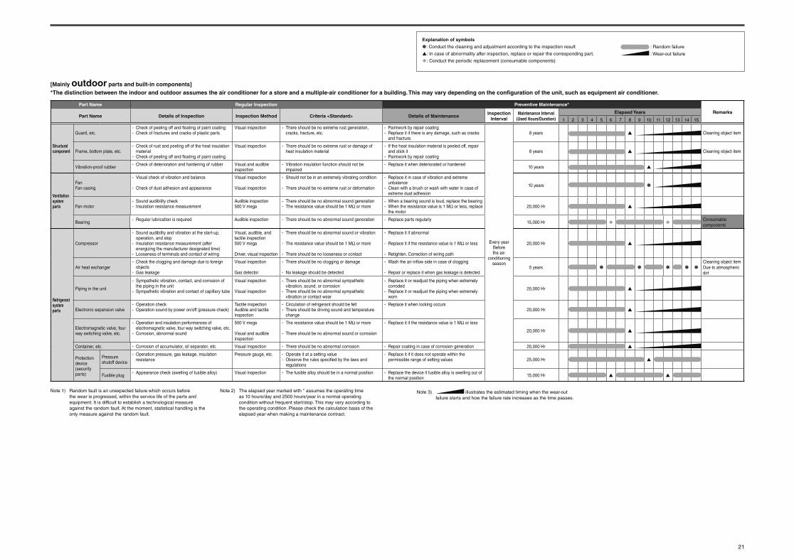
21
Part Name Regular Inspection Preventive Maintenance*
RemarksPart Name Details of Inspection Inspection Method Criteria <Standard> Details of Maintenance
Inspection Interval
Maintenance Interval(Used Hours/Duration)
Elapsed Years
1 2 3 4 5 6 7 8 9 10 11 12 13 14 15
Structural component
Guard, etc.- Check of peeling off and fl oating of paint coating- Check of fractures and cracks of plastic parts
Visual inspection - There should be no extreme rust generation, cracks, fracture, etc.
- Paintwork by repair coating- Replace it if there is any damage, such as cracks
and fracture.
Every yearBefore the air-
conditioning season
8 years Cleaning object item
Frame, bottom plate, etc.- Check of rust and peeling off of the heat insulation
material- Check of peeling off and fl oating of paint coating
Visual inspection - There should be no extreme rust or damage of heat insulation material
- If the heat insulation material is peeled off, repair and stick it
- Paintwork by repair coating8 years Cleaning object item
Vibration-proof rubber- Check of deterioration and hardening of rubber Visual and audible
inspection- Vibration insulation function should not be
impaired- Replace it when deteriorated or hardened
10 years
Ventilation system parts
FanFan casing
- Visual check of vibration and balance
- Check of dust adhesion and appearance
Visual inspection
Visual inspection
- Should not be in an extremely vibrating condition
- There should be no extreme rust or deformation
- Replace it in case of vibration and extreme unbalance
- Clean with a brush or wash with water in case of extreme dust adhesion
10 years
Fan motor- Sound audibility check- Insulation resistance measurement
Audible inspection500 V mega
- There should be no abnormal sound generation- The resistance value should be 1 MΩ or more
- When a bearing sound is loud, replace the bearing- When the resistance value is 1 MΩ or less, replace
the motor20,000 Hr
Bearing- Regular lubrication is required Audible inspection - There should be no abnormal sound generation - Replace parts regularly
15,000 HrConsumable components
Refrigerant system parts
Compressor
- Sound audibility and vibration at the start-up, operation, and stop
- Insulation resistance measurement (after energizing the manufacturer designated time)
- Looseness of terminals and contact of wiring
Visual, audible, and tactile inspection500 V mega
Driver, visual inspection
- There should be no abnormal sound or vibration
- The resistance value should be 1 MΩ or more
- There should be no looseness or contact
- Replace it if abnormal
- Replace it if the resistance value is 1 MΩ or less
- Retighten. Correction of wiring path
20,000 Hr
Air heat exchanger- Check the clogging and damage due to foreign
objects- Gas leakage
Visual inspection
Gas detector
- There should be no clogging or damage
- No leakage should be detected
- Wash the air infl ow side in case of clogging
- Repair or replace it when gas leakage is detected5 years
Cleaning object itemDue to atmospheric dirt
Piping in the unit
- Sympathetic vibration, contact, and corrosion of the piping in the unit
- Sympathetic vibration and contact of capillary tube
Visual inspection
Visual inspection
- There should be no abnormal sympathetic vibration, sound, or corrosion
- There should be no abnormal sympathetic vibration or contact wear
- Replace it or readjust the piping when extremely corroded
- Replace it or readjust the piping when extremely worn
20,000 Hr
Electronic expansion valve- Operation check- Operation sound by power on/off (pressure check)
Tactile inspectionAudible and tactile inspection
- Circulation of refrigerant should be felt- There should be driving sound and temperature
change
- Replace it when locking occurs20,000 Hr
Electromagnetic valve, four way switching valve, etc.
- Operation and insulation performances of electromagnetic valve, four way switching valve, etc.
- Corrosion, abnormal sound
500 V mega
Visual and audible inspection
- The resistance value should be 1 MΩ or more
- There should be no abnormal sound or corrosion
- Replace it if the resistance value is 1 MΩ or less
20,000 Hr
Container, etc. - Corrosion of accumulator, oil separator, etc. Visual inspection - There should be no abnormal corrosion - Repair coating in case of corrosion generation 20,000 Hr
Protection device(security parts)
Pressure shutoff device
- Operation pressure, gas leakage, insulation resistance
Pressure gauge, etc. - Operate it at a setting value- Observe the rules specifi ed by the laws and
regulations
- Replace it if it does not operate within the permissible range of setting values 25,000 Hr
Fusible plug- Appearance check (swelling of fusible alloy) Visual inspection - The fusible alloy should be in a normal position - Replace the device if fusible alloy is swelling out of
the normal position15,000 Hr
[Mainly outdoor parts and built-in components]
*The distinction between the indoor and outdoor assumes the air conditioner for a store and a multiple-air conditioner for a building. This may vary depending on the confi guration of the unit, such as equipment air conditioner.
Explanation of symbols
: Conduct the cleaning and adjustment according to the inspection result
: In case of abnormality after inspection, replace or repair the corresponding part.
: Conduct the periodic replacement (consumable components)
: Random failure
: Wear-out failure
Note 1) Random fault is an unexpected failure which occurs before
the wear is progressed, within the service life of the parts and
equipment. It is difficult to establish a technological measure
against the random fault. At the moment, statistical handling is the
only measure against the random fault.
Note 2) The elapsed year marked with * assumes the operating time
as 10 hours/day and 2500 hours/year in a normal operating
condition without frequent start/stop. This may vary according to
the operating condition. Please check the calculation basis of the
elapsed year when making a maintenance contract.
Note 3) illustrates the estimated timing when the wear-out
failure starts and how the failure rate increases as the time passes.
PSA012B820B_EN.indd 21PSA012B820B_EN.indd 21 2016/08/19 13:36:202016/08/19 13:36:20
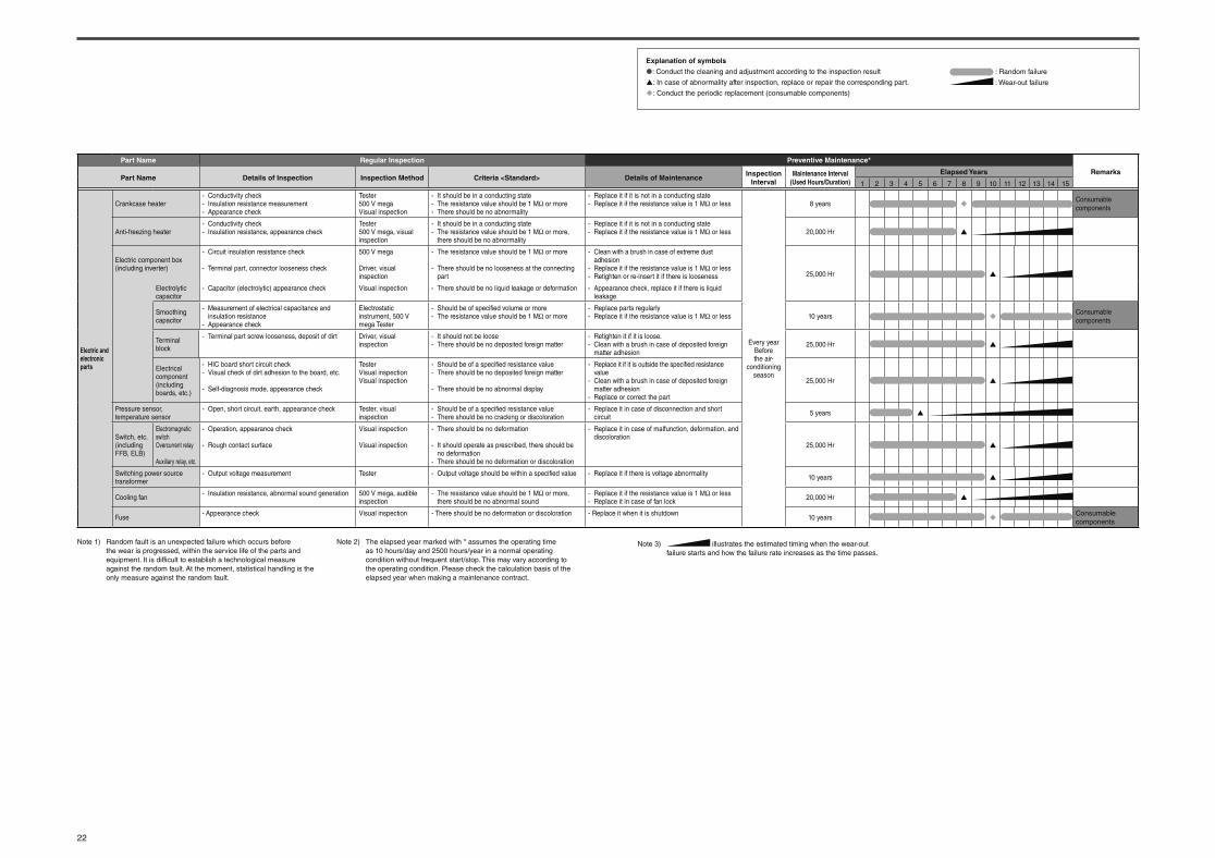
22
Explanation of symbols
: Conduct the cleaning and adjustment according to the inspection result
: In case of abnormality after inspection, replace or repair the corresponding part.
: Conduct the periodic replacement (consumable components)
: Random failure
: Wear-out failure
Part Name Regular Inspection Preventive Maintenance*
RemarksPart Name Details of Inspection Inspection Method Criteria <Standard> Details of Maintenance
Inspection Interval
Maintenance Interval(Used Hours/Duration)
Elapsed Years
1 2 3 4 5 6 7 8 9 10 11 12 13 14 15
Electric and electronic parts
Crankcase heater- Conductivity check- Insulation resistance measurement- Appearance check
Tester500 V megaVisual inspection
- It should be in a conducting state- The resistance value should be 1 MΩ or more- There should be no abnormality
- Replace it if it is not in a conducting state- Replace it if the resistance value is 1 MΩ or less
Every yearBefore the air-
conditioning season
8 yearsConsumable components
Anti-freezing heater- Conductivity check- Insulation resistance, appearance check
Tester500 V mega, visual inspection
- It should be in a conducting state- The resistance value should be 1 MΩ or more,
there should be no abnormality
- Replace it if it is not in a conducting state- Replace it if the resistance value is 1 MΩ or less 20,000 Hr
Electric component box (including inverter)
- Circuit insulation resistance check
- Terminal part, connector looseness check
500 V mega
Driver, visual inspection
- The resistance value should be 1 MΩ or more
- There should be no looseness at the connecting part
- Clean with a brush in case of extreme dust adhesion
- Replace it if the resistance value is 1 MΩ or less- Retighten or re-insert it if there is looseness 25,000 Hr
Electrolytic capacitor
- Capacitor (electrolytic) appearance check Visual inspection - There should be no liquid leakage or deformation - Appearance check, replace it if there is liquid leakage
Smoothing capacitor
- Measurement of electrical capacitance and insulation resistance
- Appearance check
Electrostatic instrument, 500 V mega Tester
- Should be of specifi ed volume or more- The resistance value should be 1 MΩ or more
- Replace parts regularly- Replace it if the resistance value is 1 MΩ or less 10 years
Consumable components
Terminal block
- Terminal part screw looseness, deposit of dirt Driver, visual inspection
- It should not be loose- There should be no deposited foreign matter
- Retighten it if it is loose.- Clean with a brush in case of deposited foreign
matter adhesion25,000 Hr
Electrical component(including boards, etc.)
- HIC board short circuit check- Visual check of dirt adhesion to the board, etc.
- Self-diagnosis mode, appearance check
TesterVisual inspectionVisual inspection
- Should be of a specifi ed resistance value- There should be no deposited foreign matter
- There should be no abnormal display
- Replace it if it is outside the specifi ed resistance value
- Clean with a brush in case of deposited foreign matter adhesion
- Replace or correct the part
25,000 Hr
Pressure sensor, temperature sensor
- Open, short circuit, earth, appearance check Tester, visual inspection
- Should be of a specifi ed resistance value- There should be no cracking or discoloration
- Replace it in case of disconnection and short circuit
5 years
Switch, etc.(including FFB, ELB)
Electromagnetic switchOvercurrent relay
Auxiliary relay, etc.
- Operation, appearance check
- Rough contact surface
Visual inspection
Visual inspection
- There should be no deformation
- It should operate as prescribed, there should be no deformation
- There should be no deformation or discoloration
- Replace it in case of malfunction, deformation, and discoloration
25,000 Hr
Switching power source transformer
- Output voltage measurement Tester - Output voltage should be within a specifi ed value - Replace it if there is voltage abnormality10 years
Cooling fan- Insulation resistance, abnormal sound generation 500 V mega, audible
inspection- The resistance value should be 1 MΩ or more,
there should be no abnormal sound- Replace it if the resistance value is 1 MΩ or less- Replace it in case of fan lock
20,000 Hr
Fuse- Appearance check Visual inspection - There should be no deformation or discoloration - Replace it when it is shutdown
10 yearsConsumable components
Note 1) Random fault is an unexpected failure which occurs before
the wear is progressed, within the service life of the parts and
equipment. It is difficult to establish a technological measure
against the random fault. At the moment, statistical handling is the
only measure against the random fault.
Note 2) The elapsed year marked with * assumes the operating time
as 10 hours/day and 2500 hours/year in a normal operating
condition without frequent start/stop. This may vary according to
the operating condition. Please check the calculation basis of the
elapsed year when making a maintenance contract.
Note 3) illustrates the estimated timing when the wear-out
failure starts and how the failure rate increases as the time passes.
PSA012B820B_EN.indd 22PSA012B820B_EN.indd 22 2016/08/19 13:36:202016/08/19 13:36:20
MITSUBISHI HEAVY INDUSTRIES THERMAL SYSTEMS, LTD.16-5 Konan 2-chome, Minato-ku, Tokyo, 108-8215, Japan
http://www.mhi-mth.co.jp/
MITSUBISHI HEAVY INDUSTRIES AIR-CONDITIONING EUROPE, LTD.7 Roundwood Avenue, Stockley Park, Uxbridge, Middlesex, UB11 1AX, United Kingdom
Tel : +44-20-7025-2750
Fax : +44-20-7025-2751
http ://www.mhiae.com
MITSUBISHI HEAVY INDUSTRIES AIR-CONDITIONERS AUSTRALIA, PTY. LTD.9C Commercial Road Kingsgrove NSW 2208 PO BOX 318 Kingsgrove NSW 1480
Tel : +61-2-8571-7977
Fax : +61-2-8571-7992
http ://www.mhiaa.com.au
MITSUBISHI HEAVY INDUSTRIES - MAHAJAK AIR CONDITIONERS CO., LTD.220, Soi Chalongkrung 31,
Kwang Lamplatiew, Khet Lad Krabang, Bangkok 10520, Thailand
Tel : +66-2-326-0401
Fax : +66-2-326-0419
http ://www.maco.co.th/
PSA012B820D_cover.indd 4PSA012B820D_cover.indd 4 2016/11/19 14:07:062016/11/19 14:07:06