Embed Size (px)
Citation preview
9/2000
Position Display Units
for Milling Machines
User’s Manual
����������
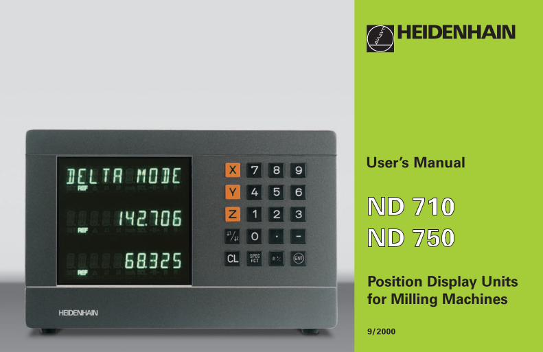
Position display
(ND 710 only two axes)
∆ = Distance-to-go display
R+/– = Radius compensation
Numerical input
• Change the algebraic sign
• Call the last dialog
• In the parameter list:
change parameters
Call radius compensation
of the current tool
• Select special functions
• In the list of special functions
page forward
• Cancel entry
• Reset the operating mode
• Zero the selected axis
(if activated in P80)
• Select parameters
CL plus two-digit number
Status display:
SCL = Scaling factor
->❘❘<- = Touching the edge / centerlineR = Radius/diameter display
• Select datum 1 or 2
• Page backward in the list of
special functions
• Page backward in the list of
parameters
1 2 Datum 1 or 2
SET = Datum settingREF = blinking:
Traverse thereference points.On continuously:Reference pointshave been traversed.
Inch = Display in inches
• Select coordinate axes
(ND 710 only X and Y)
• Select axis-specific operating parameters
• Confirm entry
• In the parameter list
page forward
Part
I O
pera
tin
g In
str
ucti
on
s
3
This manual is for the ND display units with thefollowing software numbers or higher:
ND 710 for two axes 246 271-06
ND 750 for three axes 246 271-06
About this manual
This manual is divided into two parts:
Part I: Operating Instructions
• Fundamentals of positioning• ND functions
Part II: Installation and Specifications
• Mounting the display unit on the machine• Description of operating parameters
Part I Operating Instructions
Fundamentals 4
Switch-On, Traversing the Reference Points 9
Datum Setting 10
Tool Compensation 19
Moving the Axes with Distance-To-Go 20
Bolt Hole Circles and Bolt Hole Circle Segments 22
Linear Hole Patterns 25
Working with a Scaling Factor 28
Error Messages 29
Part II
Installation and
Specifications Page 31
4
Y
X
Z
+Y
+X
+Z
–Z –Y
–X Datum ororigin
Graduation
Fu
nd
am
en
tals
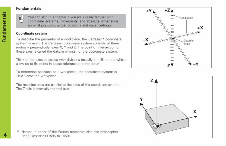
Fundamentals
You can skip this chapter if you are already familiar withcoordinate systems, incremental and absolute dimensions,nominal positions, actual positions and distance-to-go.
Coordinate system
To describe the geometry of a workpiece, the Cartesian* coordinatesystem is used. The Cartesian coordinate system consists of threemutually perpendicular axes X, Y and Z. The point of intersection ofthese axes is called the datum or origin of the coordinate system.
Think of the axes as scales with divisions (usually in millimeters) whichallow us to fix points in space referenced to the datum.
To determine positions on a workpiece, the coordinate system is“ laid” onto the workpiece.
The machine axes are parallel to the axes of the coordinate system.The Z axis is normally the tool axis.
1) Named in honor of the French mathematician and philosopherRené Descartes (1596 to 1650)
5
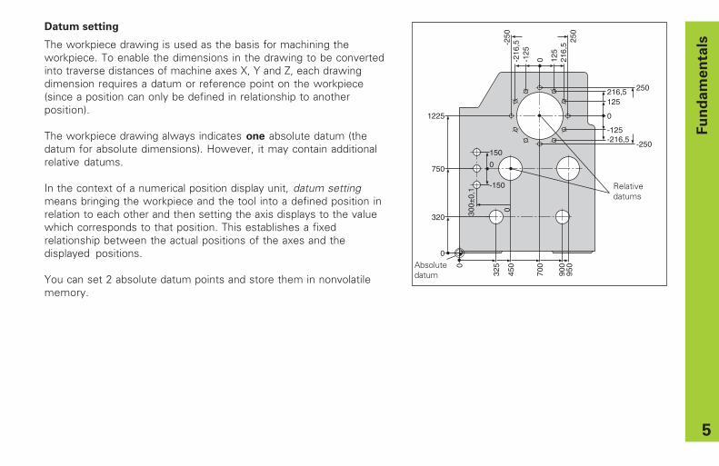
Datum setting
The workpiece drawing is used as the basis for machining theworkpiece. To enable the dimensions in the drawing to be convertedinto traverse distances of machine axes X, Y and Z, each drawingdimension requires a datum or reference point on the workpiece(since a position can only be defined in relationship to anotherposition).
The workpiece drawing always indicates one absolute datum (thedatum for absolute dimensions). However, it may contain additionalrelative datums.
In the context of a numerical position display unit, datum settingmeans bringing the workpiece and the tool into a defined position inrelation to each other and then setting the axis displays to the valuewhich corresponds to that position. This establishes a fixedrelationship between the actual positions of the axes and thedisplayed positions.
You can set 2 absolute datum points and store them in nonvolatilememory.
0
325
450
700
900
950
0
320
750
1225
300±
0,1
0
150
-150
0
0
216,5 250
-250
-125-216,5
0-125
-216
,5-250 250
125
216,
5
125
Relativedatums
Fu
nd
am
en
tals
Absolutedatum
6
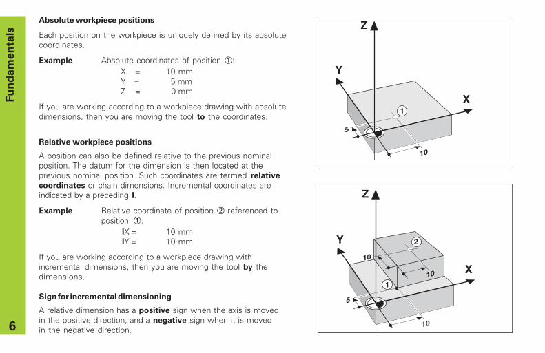
Absolute workpiece positions
Each position on the workpiece is uniquely defined by its absolutecoordinates.
Example Absolute coordinates of position 1:X = 10 mmY = 5 mmZ = 0 mm
If you are working according to a workpiece drawing with absolutedimensions, then you are moving the tool to the coordinates.
�
�
�
��
�
�
Fu
nd
am
en
tals
1
Y
X
Z
10
5
10
10
1
2
Relative workpiece positions
A position can also be defined relative to the previous nominalposition. The datum for the dimension is then located at theprevious nominal position. Such coordinates are termed relative
coordinates or chain dimensions. Incremental coordinates areindicated by a preceding I.
Example Relative coordinate of position 2 referenced toposition 1:
IX = 10 mmIY = 10 mm
If you are working according to a workpiece drawing withincremental dimensions, then you are moving the tool by thedimensions.
Sign for incremental dimensioning
A relative dimension has a positive sign when the axis is movedin the positive direction, and a negative sign when it is movedin the negative direction.

7
Nominal position, actual position and distance-to-go
The position to which the tool is to move is called the nominal
position ( S ). The position at which the tool is actually located at any
given moment is called the actual position ( I ).
The distance from the nominal position to the actual position is called
the distance-to-go ( R ).
Sign for distance-to-go
When you are using the distance-to-go display, the nominal positionbecomes the relative datum (display value 0). The distance-to-go istherefore negative when you move in the positive axis direction, andpositive when you move in the negative axis direction.
Fu
nd
am
en
tals
Y
X
ZI
S
R

8
Position encoders
The position encoders on the machine convert the movements of themachine axes into electrical signals. The ND display unit evaluatesthese signals, determines the actual position of the machine axes anddisplays the position as a numerical value.
If the power is interrupted, the relationship between the machine axispositions and the calculated actual positions is lost. The referencemarks on the position encoders and the REF reference markevaluation feature enable the ND to quickly re-establish thisrelationship again when the power is restored.
Reference marks
The scales of the position encoders contain one or more referencemarks. When a reference mark is crossed over, a signal is generatedwhich identifies that position as a reference point (scale datum =machine datum).
When this reference mark is crossed over, the ND's reference markevaluation feature (REF) restores the relationship between axis slidepositions and display values which you last defined by setting thedatum. If the linear encoders have distance-coded reference marks,you only need to move the machine axes a maximum of 20 mm to dothis.
�
�
�
Workpiece
Position encoder
Scale in Distance-coded linear encoder reference marks
Reference mark
Fu
nd
am
en
tals

9
Switch-On, Traversing the Reference Marks
ENT...CL
Turn on power (switch located on rear panel).REF and decimal points in status display blink.
Confirm reference traverse mode. REF remainson continuously. Decimal points blink.
Cross over the reference marks in all axes (in anysequence). Each axis display becomes activewhen its reference mark is crossed over.
0 � 1
ENT
Crossing over the reference marks stores the last relationshipbetween axis slide positions and display values for datum points 1 and2 in nonvolatile memory.
Note that if you choose not to traverse the reference marks (byclearing the dialog ENT ... CL with the CL key), this relationship will belost if the power is interrupted or when the unit is switched off. S
wit
ch
-On
, T
ravers
ing
th
e R
efe
ren
ce M
ark
s
If you wish to use multipoint axis error compensation youmust traverse the reference marks (see “ Multipoint axis errorcompensation” )!
10
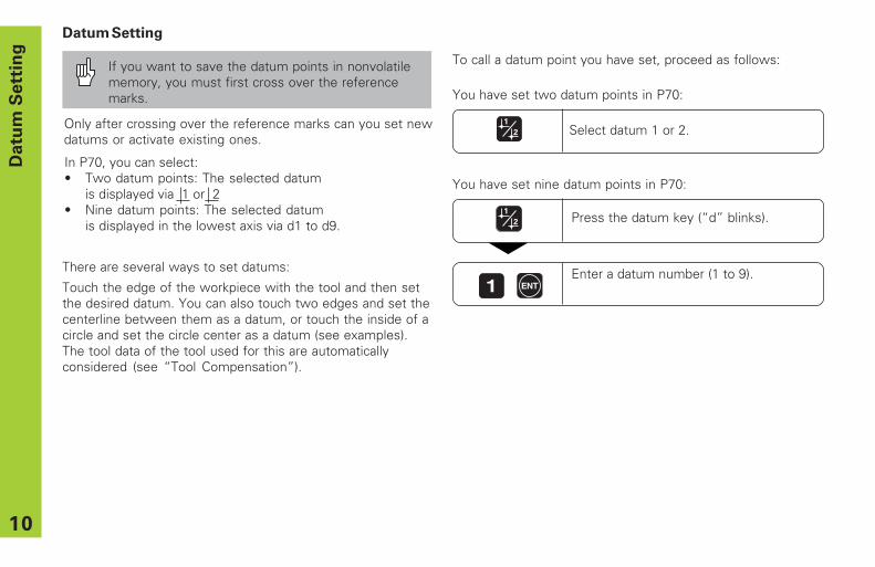
Datum Setting
If you want to save the datum points in nonvolatilememory, you must first cross over the referencemarks.
Only after crossing over the reference marks can you set newdatums or activate existing ones.
Datu
m S
ett
ing
There are several ways to set datums:
Touch the edge of the workpiece with the tool and then setthe desired datum. You can also touch two edges and set thecenterline between them as a datum, or touch the inside of acircle and set the circle center as a datum (see examples).The tool data of the tool used for this are automaticallyconsidered (see “ Tool Compensation” ).
In P70, you can select:• Two datum points: The selected datum
is displayed via 1 or 2• Nine datum points: The selected datum
is displayed in the lowest axis via d1 to d9.Press the datum key (“ d” blinks).
Enter a datum number (1 to 9).1 ENT
To call a datum point you have set, proceed as follows:
You have set two datum points in P70:
Select datum 1 or 2.
You have set nine datum points in P70:
11
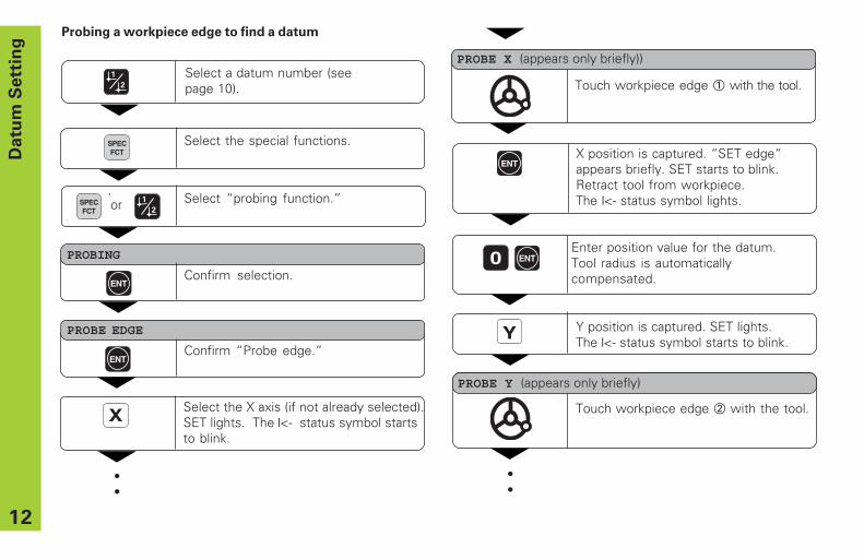
Probing a workpiece edge to find a datum
The ND display units support the following probing functions:
“ PROBE EDGE” Setting a workpiece edge as datum.
“ PROBE MIDPOINT” Setting a midpoint between twoworkpiece edges as datum.
“ PROBE CIRCLE” Setting the center of a circle as datum.
The probing functions are accessible in the SPEC FCT mode ofoperation. The functions “ PROBE EDGE” , “ PROBE MIDPOINT” and “ PROBECIRCLE” are described on the following pages.
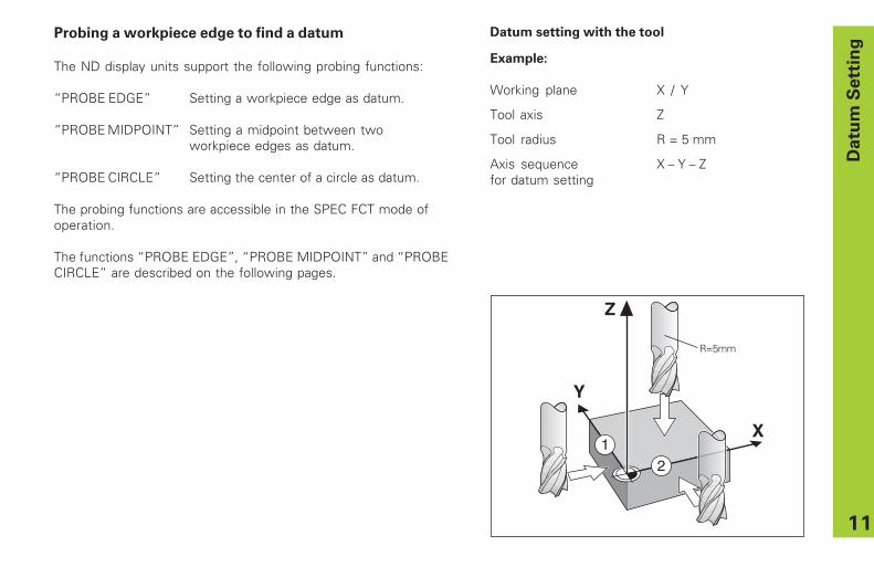
Datu
m S
ett
ing
Y
X
21
Z
R=5mm
Datum setting with the tool
Example:
Working plane X / Y
Tool axis Z
Tool radius R = 5 mm
Axis sequence X – Y – Zfor datum setting
12
Datu
m S
ett
ing
Select the special functions.SPECFCT
PROBE EDGE
ENTConfirm “ Probe edge.”
•••
X Select the X axis (if not already selected).SET lights. The ❘<- status symbol startsto blink.
ENTX position is captured. “ SET edge“appears briefly. SET starts to blink.Retract tool from workpiece.The ❘<- status symbol lights.
Enter position value for the datum.Tool radius is automaticallycompensated.
0
Y Y position is captured. SET lights.The ❘<- status symbol starts to blink.
ENT
••
Select “ probing function.”
PROBING
ENTConfirm selection.
SPECFCT
••
Touch workpiece edge 1 with the tool.
PROBE X (appears only briefly))
Touch workpiece edge 2 with the tool.
PROBE Y (appears only briefly)
or
Select a datum number (seepage 10).
Probing a workpiece edge to find a datum
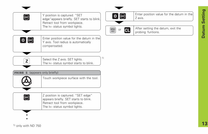
13
Datu
m S
ett
ing
Z Select the Z axis. SET lights.The ❘<- status symbol starts to blink.
Touch workpiece surface with the tool.
ENTZ position is captured. “ SET edge“appears briefly. SET starts to blink.Retract tool from workpiece.The ❘<- status symbol lights.
Enter position value for the datum in theZ axis.0 ENT
After setting the datum, exit theprobing funtions.
PROBE Z (appears only briefly)
SPECFCT
or CL
1) only with ND 750
1)
Enter position value for the datum in theY axis. Tool radius is automaticallycompensated.
0 ENT
ENTY position is captured. “ SETedge“ appears briefly. SET starts to blink.Retract tool from workpiece.The ❘<- status symbol lights.
••

14
Probing workpiece edges to find a midpoint datum
The edges to be probed run parallel to the Y axis.
Follow the procedure below for all midpoints between two edges:
Datu
m S
ett
ing
Select the special functions.SPECFCT
•••
Select the probing function.
PROBING
ENTConfirm selection.
SPECFCT
or
Select a datum number (see page 10).
Y
X
2
1
Z
MX?

15
Datu
m S
ett
ing
XSelect the X axis (if not already selected)and confirm with ENT. The ->❘❘<- symbolstarts to blink.
Touch workpiece edge 1 with the tool.
Touch workpiece edge 2 with thetool.
2 6 Enter position value for the midpointbetween the two edges, e.g. 26.
Exit the probing functions.
ENT
ENTConfirm “ Probe midpoint.”SET lights.
PROBE MIDP.
ENT
SPECFCT CL or
1ST POS X (appears only briefly)
2ND POS X (appears only briefly)
ANTASTEN MITTE Select “ Probe midpoint.”
PROBE EDGE
or
•••
Position value 1 is captured.ENT
Retract tool from workpiece.
“ SET MIDPOINT” appears briefly. SETstarts to blink. Retract tool fromworkpiece. The ❘<- status symbol startsto blink..
ENT
16
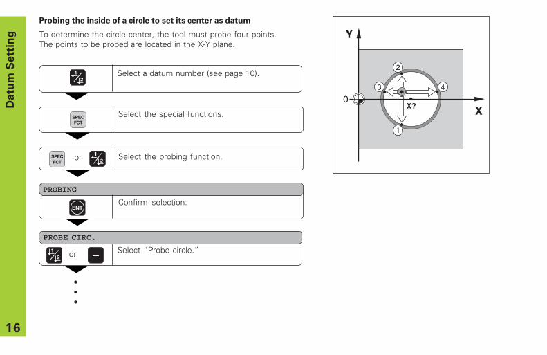
Probing the inside of a circle to set its center as datum
To determine the circle center, the tool must probe four points.The points to be probed are located in the X-Y plane.
Datu
m S
ett
ing
Select the special functions.SPECFCT
•••
Select the probing function.
PROBING
ENTConfirm selection.
SPECFCT
or
Select a datum number (see page 10).
ANTASTEN MITTE Select “ Probe circle.”
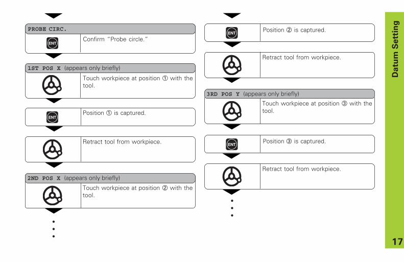
PROBE CIRC.
or
Y
X0
1
2
3 4
X?
17
Datu
m S
ett
ing
Touch workpiece at position 1 with thetool.
Touch workpiece at position 2 with thetool.
ENT
PROBE CIRC.
1ST POS X (appears only briefly)
2ND POS X (appears only briefly)
•••
Confirm “ Probe circle.”
Touch workpiece at position 3 with thetool.
3RD POS Y (appears only briefly)
ENTPosition 1 is captured.
Retract tool from workpiece.
ENT
Retract tool from workpiece.
Position 2 is captured.
ENT
Retract tool from workpiece.
Position 3 is captured.
•••
18
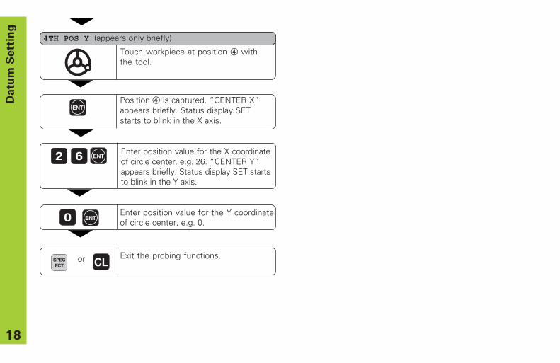
2 6 Enter position value for the X coordinateof circle center, e.g. 26. “ CENTER Y”appears briefly. Status display SET startsto blink in the Y axis.
Exit the probing functions.
ENT
SPECFCT CL or
Touch workpiece at position 4 withthe tool.
4TH POS Y (appears only briefly)
Enter position value for the Y coordinateof circle center, e.g. 0.0 ENT
ENTPosition 4 is captured. “ CENTER X”appears briefly. Status display SETstarts to blink in the X axis.
Datu
m S
ett
ing
19
To
ol
Co
mp
en
sa
tio
n
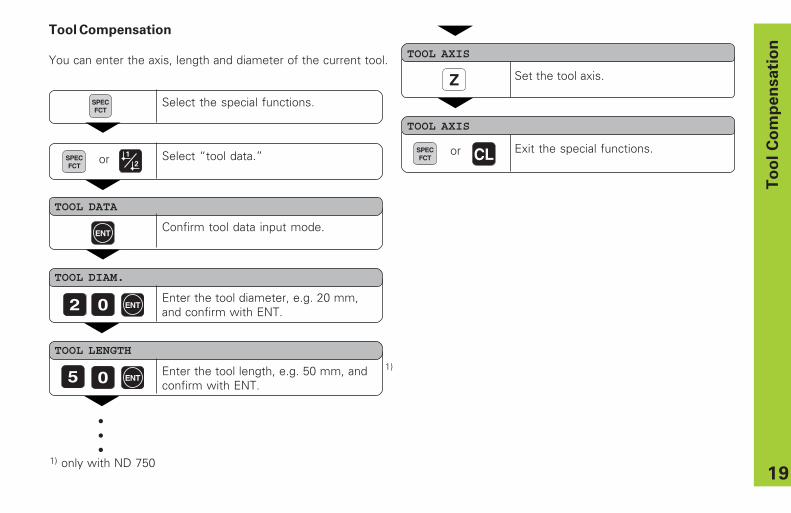
Tool Compensation
You can enter the axis, length and diameter of the current tool.
Select the special functions.
TOOL DIAM.
2 0 Enter the tool diameter, e.g. 20 mm,and confirm with ENT.
TOOL AXIS
Z Set the tool axis.
SPECFCT
ENT
TOOL DATA
ENTConfirm tool data input mode.
Select “ tool data.”SPECFCT
TOOL LENGTH
0 ENT5
TOOL AXIS
Exit the special functions.
•••
SPECFCT CL or
1) only with ND 750
or
1)Enter the tool length, e.g. 50 mm, andconfirm with ENT.
20
Mo
vin
g t
he
Ax
es w
ith
Dis
tan
ce
-To
-Go
Dis
pla
y
Select the special functions.
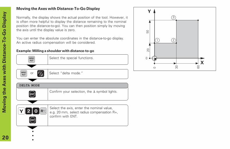
Moving the Axes with Distance-To-Go Display
Normally, the display shows the actual position of the tool. However, itis often more helpful to display the distance remaining to the nominalposition (the distance-to-go). You can then position simply by movingthe axis until the display value is zero.
You can enter the absolute coordinates in the distance-to-go display.An active radius compensation will be considered.
Example: Milling a shoulder with distance-to-go
R+-
Select the axis, enter the nominal value,e.g. 20 mm, select radius compensation R+,confirm with ENT.
ENT
Y 02
Confirm your selection, the ∆ symbol lights.ENT
DELTA MODE
SPECFCT
•••
Select “ delta mode.”SPECFCT
or
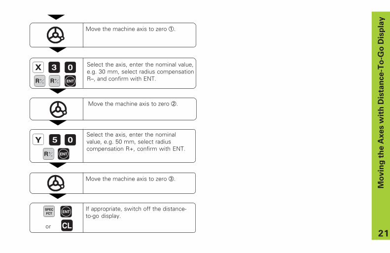
21
Y 0Select the axis, enter the nominalvalue, e.g. 50 mm, select radiuscompensation R+, confirm with ENT.
ENTR+-
Mo
vin
g t
he
Ax
es w
ith
Dis
tan
ce
-To
-Go
Dis
pla
y
X 03 Select the axis, enter the nominal value,e.g. 30 mm, select radius compensationR– , and confirm with ENT.ENT
Move the machine axis to zero 2.
R+-
Move the machine axis to zero 1.
5
Move the machine axis to zero 3.
If appropriate, switch off the distance-to-go display.
SPECFCT ENT
CLor
R+-

22
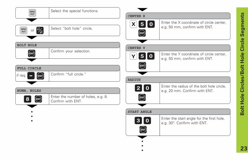
Bolt Hole Circles and Bolt Hole Circle Segments
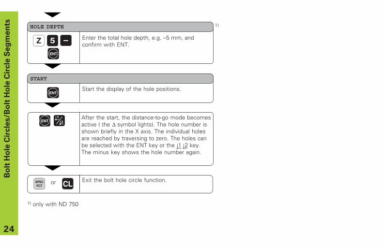
Your display unit enables you to quickly and easily drill bolt hole circlesand bolt hole circle segments. The required data is requested in themessage field.
Each hole can be moved to by traversing to display value zero. Thisrequires entry of the following data:
• Number of holes (maximum: 999)• Circle center• Circle radius• Starting angle for first hole• Angle step between the holes (only for circle segments)• Hole depth
Example
Number of holes 8Coordinates of the center X = 50 mm
Y = 50 mmCircle radius 20 mmStarting angle 30 degreesHole depth Z = – 5 mmB
olt
Ho
le C
ircle
s/B
olt
Ho
le C
ircle
Se
gm
en
ts
Y
X
30°
R20
50
50
0
0
23
Bo
lt H
ole
Cir
cle
s/B
olt
Ho
le C
ircle
Se
gm
en
ts
Select the special functions.SPECFCT
FULL CIRCLE
ENT
NUMB. HOLES
8 Enter the number of holes, e.g. 8.Confirm with ENT.
•••
CENTER Y
5 0Y
CENTER X
X 5 0
Enter the Y coordinate of circle center,e.g. 50 mm, confirm with ENT.
02
RADIUS
START ANGLE
03
Enter the X coordinate of circle center,e.g. 50 mm, confirm with ENT.
Enter the radius of the bolt hole circle,e.g. 20 mm. Confirm with ENT.
Enter the start angle for the first hole,e.g. 30° . Confirm with ENT.
•••
ENT
ENT
ENT
ENT
ENT
Select “ bolt hole” circle.SPECFCT
BOLT HOLE
ENTConfirm your selection.
or
if req. Confirm “ full circle.”
24
Bo
lt H
ole
Cir
cle
s/B
olt
Ho
le C
ircle
Se
gm
en
ts
Enter the total hole depth, e.g. – 5 mm, andconfirm with ENT.
HOLE DEPTH
5
START
ENTStart the display of the hole positions.
After the start, the distance-to-go mode becomesactive ( the ∆ symbol lights). The hole number isshown briefly in the X axis. The individual holesare reached by traversing to zero. The holes canbe selected with the ENT key or the 1 2 key.The minus key shows the hole number again.
ENT
ENT
Exit the bolt hole circle function.SPECFCT
or CL
1) only with ND 750
1)
Z

25
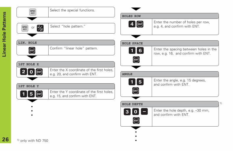
Linear Hole Patterns
The linear hole pattern feature allows you to easily create rows ofholes to cover an area. The required data are requested in themessage field.
You can position to each hole by traversing to display value zero.The following data are required:
• Coordinates of the first hole• Number of holes per row (maximum: 999)• Spacing between holes• Angle between the rows and the reference axis• Hole depth• Number of rows (maximum: 999)• Spacing between rows
Example
Coordinates of the first hole X = 20 mmY = 15 mm
Number of holes per row 4Spacing between holes 16 mmAngle 15 degreesHole depth Z = – 30 mmNumber of rows 3Spacing between rows 20 mm
Lin
ear
Ho
le P
att
ern
s
Y
X
20
151
16
2 3 45 6
7 8
15°
20
9
12
0
0
26
Select the special functions.SPECFCT
LIN. HOLE
ENTConfirm “ linear hole” pattern.
1ST HOLE X
Enter the X coordinate of the first holes,e.g. 20, and confirm with ENT.
HOLES ROW
Enter the number of holes per row,e.g. 4, and confirm with ENT.
02
1ST HOLE Y
Enter the Y coordinate of the first holes,e.g. 15, and confirm with ENT.
•••
51
4
HOLE SPACE
Enter the spacing between holes in therow, e.g. 16, and confirm with ENT.
ANGLE
HOLE DEPTH
Enter the angle, e.g. 15 degrees,and confirm with ENT.
Enter the hole depth, e.g. – 30 mm,and confirm with ENT.
•••
61
1 5
3 0
Lin
ear
Ho
le P
att
ern
s
ENT
ENT
ENT
ENT
ENT
ENT
Select “ hole pattern.”SPECFCT
1) only with ND 750
1)
or
27
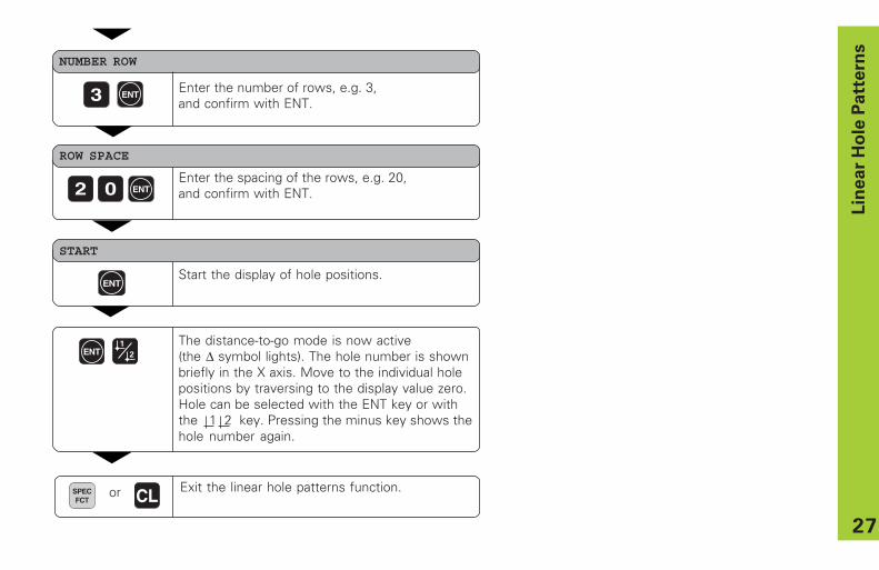
NUMBER ROW
3
ROW SPACE
Enter the spacing of the rows, e.g. 20,and confirm with ENT.
Enter the number of rows, e.g. 3,and confirm with ENT.
Lin
ear
Ho
le P
att
ern
s
02
START
ENTStart the display of hole positions.
The distance-to-go mode is now active(the ∆ symbol lights). The hole number is shownbriefly in the X axis. Move to the individual holepositions by traversing to the display value zero.Hole can be selected with the ENT key or withthe 1 2 key. Pressing the minus key shows thehole number again.
ENT
ENT
ENT
Exit the linear hole patterns function.SPECFCT
or CL

28
Y
X
0
0
1
2
∗ 3.
0
∗ 3.5
If a scaling factor is active, SCL lights in the status display.
Working with a Scaling Factor
Scaling factors enable you to increase or decrease the display valuesbased on the actual traverse distance. The display values are changedsymmetrically about the datum.
Enter scaling factors separately for each axis in parameter P12.
Parameter P11 activates and deactivates the scaling factors in all axes(see “ Operating Parameters” ).
Example for enlarging a workpiece:
P12.1 3.5P12.2 3.0P11 ON
This results in a larger workpiece as shown in the illustration at right:1 is the original size, 2 is with axis-specific scaling factors.
Scalin
g F
acto
r
29
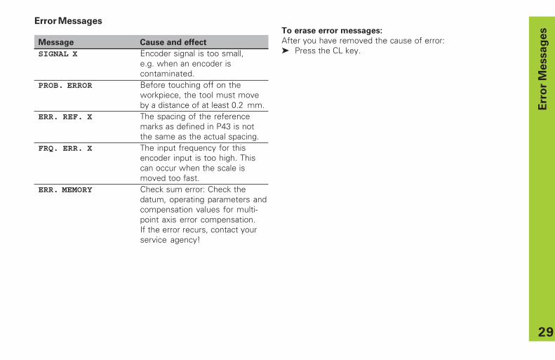
To erase error messages:
After you have removed the cause of error:➤ Press the CL key.
Error Messages
Message Cause and effect
SIGNAL X Encoder signal is too small,e.g. when an encoder iscontaminated.
PROB. ERROR Before touching off on theworkpiece, the tool must moveby a distance of at least 0.2 mm.
ERR. REF. X The spacing of the referencemarks as defined in P43 is notthe same as the actual spacing.
FRQ. ERR. X The input frequency for thisencoder input is too high. Thiscan occur when the scale ismoved too fast.
ERR. MEMORY Check sum error: Check thedatum, operating parameters andcompensation values for multi-point axis error compensation.If the error recurs, contact yourservice agency!
Err
or
Messag
es

31
Part II Installation and
Specifications
Items Supplied 32
Connections on Rear Panel 33
Mounting 34
Power Connection 34
Connecting the Encoders 35
Operating Parameters 36Entering/changing operating parameters 36Operating parameter list 37
Linear Encoders 39Setting the display step 39Display step, signal period, and subdivision 39Parameter settings for HEIDENHAIN linear encoderswith 11 µApp 40
Multipoint Axis Error Compensation 41
Specifications 44Dimensions of the ND 710/ND 750 45
Part
II
Insta
llati
on
an
d S
pecif
icati
on
s
32
Ite
ms S
up
pli
ed
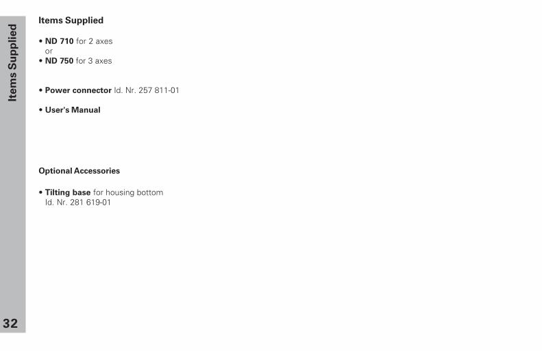
Items Supplied
• ND 710 for 2 axesor
• ND 750 for 3 axes
• Power connector Id. Nr. 257 811-01
• User's Manual
Optional Accessories
• Tilting base for housing bottomId. Nr. 281 619-01
33
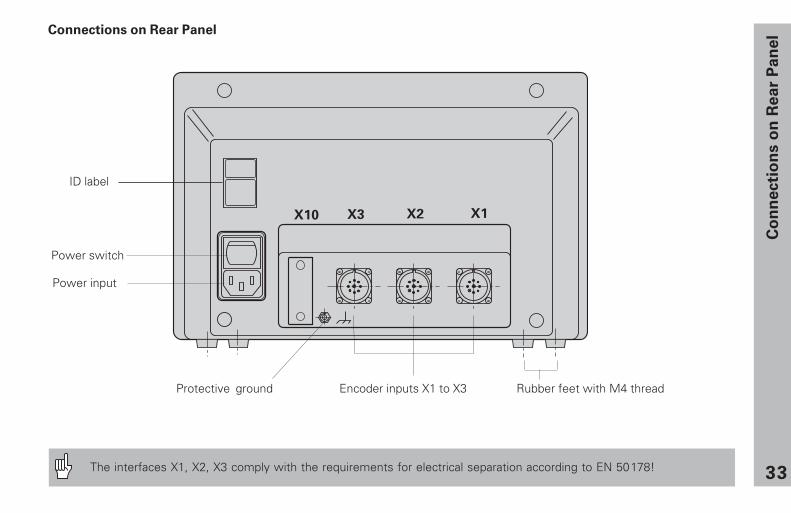
Power switch
ID label
Co
nn
ecti
on
s o
n R
ea
r P
an
el
Protective ground Encoder inputs X1 to X3 Rubber feet with M4 thread
Connections on Rear Panel
Power input
The interfaces X1, X2, X3 comply with the requirements for electrical separation according to EN 50178!
34
Mo
un
tin
g/P
ow
er
Co
nn
ecti
on
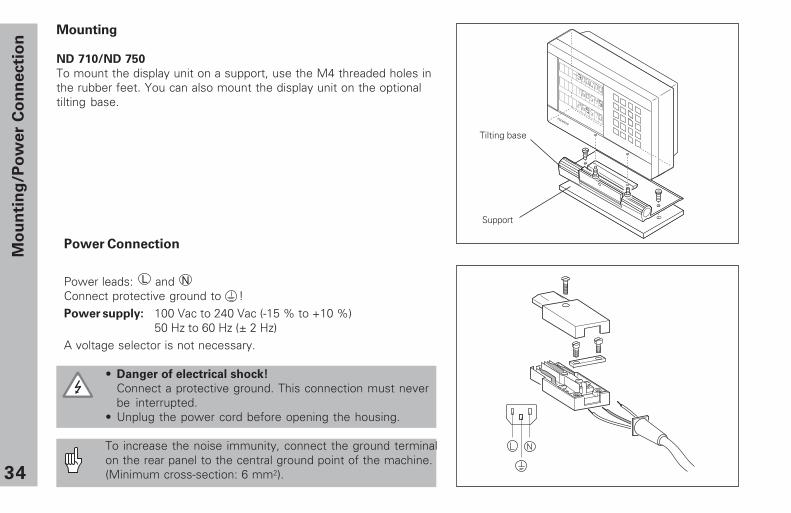
Mounting
ND 710/ND 750
To mount the display unit on a support, use the M4 threaded holes inthe rubber feet. You can also mount the display unit on the optionaltilting base.
Power Connection
Power leads: L andConnect protective ground to !Power supply: 100 Vac to 240 Vac (-15 % to +10 %)
50 Hz to 60 Hz (± 2 Hz)A voltage selector is not necessary.
• Danger of electrical shock!
Connect a protective ground. This connection must neverbe interrupted.
• Unplug the power cord before opening the housing.
To increase the noise immunity, connect the ground terminalon the rear panel to the central ground point of the machine.(Minimum cross-section: 6 mm2).
N
����������
Tilting base
Support
35
Co
nn
ecti
ng
th
e E
nco
de
rs
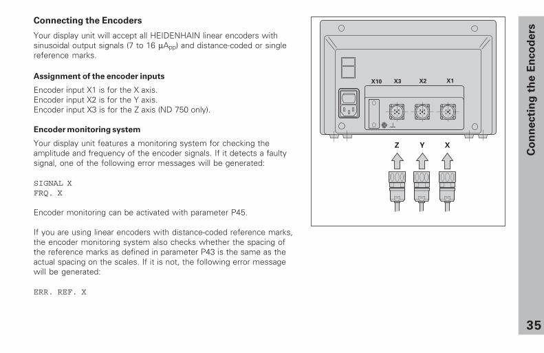
Connecting the Encoders
Your display unit will accept all HEIDENHAIN linear encoders withsinusoidal output signals (7 to 16 µApp) and distance-coded or singlereference marks.
Assignment of the encoder inputs
Encoder input X1 is for the X axis.Encoder input X2 is for the Y axis.Encoder input X3 is for the Z axis (ND 750 only).
Encoder monitoring system
Your display unit features a monitoring system for checking theamplitude and frequency of the encoder signals. If it detects a faultysignal, one of the following error messages will be generated:
SIGNAL XFRQ. X
Encoder monitoring can be activated with parameter P45.
If you are using linear encoders with distance-coded reference marks,the encoder monitoring system also checks whether the spacing ofthe reference marks as defined in parameter P43 is the same as theactual spacing on the scales. If it is not, the following error messagewill be generated:
ERR. REF. X
� � �
36
Op
era
tin
g P
ara
mete
rsOperating Parameters
Operating parameters allow you to modify the operatingcharacteristics of your display unit and define the evaluationof the encoder signals. Operating parameters that can bechanged by the user are called user parameters, and can beaccessed with the SPEC FCT key and the dialog“ PARAMETER” (user parameters are identified as such in theparameter list). The full range of parameters can only beaccessed through the dialog “ CODE“ and by entering 95148.Operating parameters are designated by the letter P and anumber. Example: P11..... The parameter designation is shownin the input field when you select it with the DATUM andENT key in the X display. The parameter setting is shown inthe Y display.
Some operating parameters have separate values for eachaxis. In the ND 750, these parameters are identified by anindex of 1 to 3, and in the ND 710 by an index of one to two.Example: P12.1 scaling factor, X axis
P12.2 scaling factor, Y axisP12.3 scaling factor, Z axis (ND 750 only)
The operating parameters are preset before the unit leavesthe factory. These factory settings are indicated in theparameter list in boldface type.
Entering and changing operating parameters
To access the operating parameters
➤ Press the SPEC FCT key.➤ Press the SPEC FCT key or 1 2 , until
“ PARAMETER” appears in the X display.➤ Confirm your selection by pressing “ ENT.”
To select protected operating parameters
➤ Press the 1 2 key to select user parameterP00 CODE.
➤ Enter the code number 95148.➤ Confirm with “ ENT.”
To page through the operating parameters
➤ Page forwards by pressing the ENT key.➤ Page backwards by pressing the 1 2 key.
To change parameter settings
➤ Press the minus key or enter the value and confirmwith the ENT key.
To correct an entry
➤ Press CL: the old value reappears in the input line andbecomes effective again.
To leave the operating parameters
➤ Press the SPEC FCT or CL key.
37
Op
era
tin
g P
ara
mete
rs
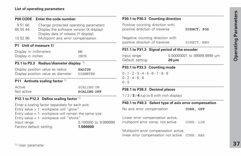
List of operating parameters
P00 CODE Enter the code number:
9 51 48: Change protected operating parameters66 55 44: Display the software version (X display)
Display date of release (Y display)10 52 96: Multipoint axis error compensation
P1 Unit of measure 1)
Display in millimeters MMDisplay in inches INCH
P3.1 to P3.3 Radius/diameter display 1)
Display position value as radius RADIUSDisplay position value as diameter DIAMETER
P11 Activate scaling factor 1)
Active SCALING ONNot active SCALING OFF
P12.1 to P12.3 Define scaling factor 1)
Enter a scaling factor separately for each axis:Entry value > 1: workpiece will “ grow”Entry value = 1: workpiece will remain the same sizeEntry value < 1: workpiece will “ shrink”Input range: 0.100000 to 9.999999Factory default setting: 1.000000
P30.1 to P30.3 Counting direction
Positive counting direction withpositive direction of traverse DIRECT. POS
Negative counting direction withpositive direction of traverse DIRECT. NEG
P31.1 to P31.3 Signal period of the encoder
Input range: 0.00000001 to 99999.9999 µmDefault setting: 20 µm
P33.1 to P33.3 Counting mode
0 - 1 - 2 - 3 - 4 - 5 - 6 - 7 - 8 - 90 - 2 - 4 - 6 - 80 - 5
P38.1 to P38.3 Decimal places
1 / 2 / 3 / 4 (up to 6 with inch display)
P40.1 to P40.3 Select type of axis error compensation
No axis error compensation CORR. OFF
Linear error compensation active,multipoint error comp. not active CORR. LIN
Multipoint error compensation active,linear error compensation not active CORR. ABS
1) User parameter
38
Op
era
tin
g P
ara
mete
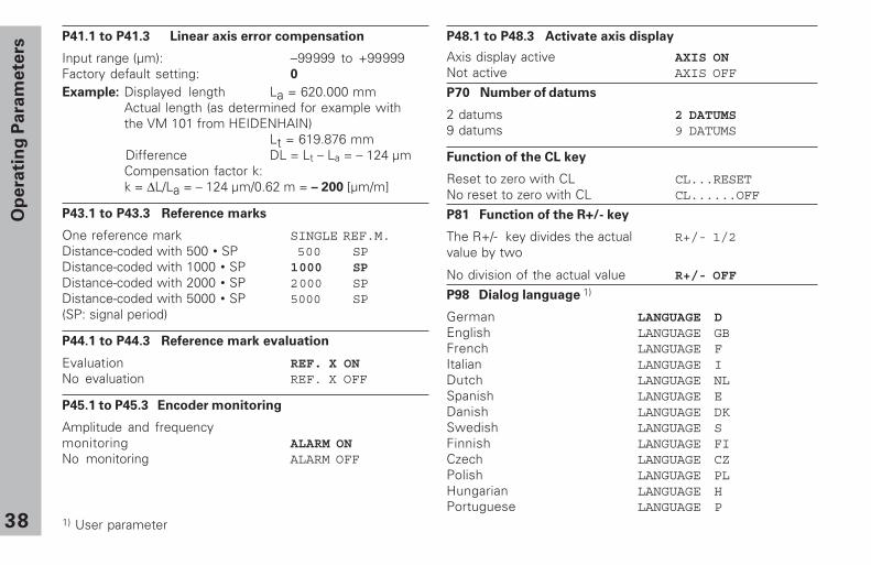
rsP41.1 to P41.3 Linear axis error compensation
Input range (µm): −99999 to +99999Factory default setting: 0
Example: Displayed length La = 620.000 mmActual length (as determined for example withthe VM 101 from HEIDENHAIN)
Lt = 619.876 mm Difference DL = Lt – La = – 124 µm
Compensation factor k:k = ∆L/La = – 124 µm/0.62 m = – 200 [µm/m]
P43.1 to P43.3 Reference marks
One reference mark SINGLE REF.M.Distance-coded with 500 • SP 500 SPDistance-coded with 1000 • SP 1000 SPDistance-coded with 2000 • SP 2000 SPDistance-coded with 5000 • SP 5000 SP(SP: signal period)
P44.1 to P44.3 Reference mark evaluation
Evaluation REF. X ONNo evaluation REF. X OFF
P45.1 to P45.3 Encoder monitoring
Amplitude and frequencymonitoring ALARM ONNo monitoring ALARM OFF
P48.1 to P48.3 Activate axis display
Axis display active AXIS ONNot active AXIS OFF
P70 Number of datums
2 datums 2 DATUMS9 datums 9 DATUMS
Function of the CL key
Reset to zero with CL CL...RESETNo reset to zero with CL CL......OFF
P81 Function of the R+/- key
The R+/- key divides the actual R+/- 1/2value by two
No division of the actual value R+/- OFF
P98 Dialog language 1)
German LANGUAGE DEnglish LANGUAGE GBFrench LANGUAGE FItalian LANGUAGE IDutch LANGUAGE NLSpanish LANGUAGE EDanish LANGUAGE DKSwedish LANGUAGE SFinnish LANGUAGE FICzech LANGUAGE CZPolish LANGUAGE PLHungarian LANGUAGE HPortuguese LANGUAGE P
1) User parameter
39
Lin
ear
En
co
ders
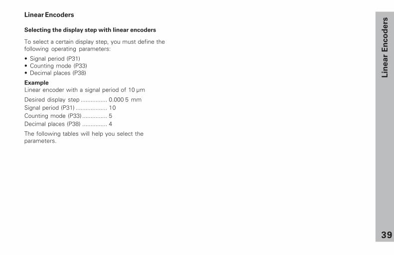
Linear Encoders
Selecting the display step with linear encoders
To select a certain display step, you must define thefollowing operating parameters:
• Signal period (P31)• Counting mode (P33)• Decimal places (P38)
Example
Linear encoder with a signal period of 10 µm
Desired display step ................ 0.000 5 mmSignal period (P31) ................... 10Counting mode (P33) ............... 5Decimal places (P38) ............... 4
The following tables will help you select theparameters.

40
Lin
ear
En
co
ders
Parameter settings for HEIDENHAIN linear encoders with 11 µAPP
signals
Millimeters Inches
Sig
na
l pe
rio
d
[µm
]
Reference
marks
Co
un
t
De
cim
al
pla
ce
s
Co
un
t
De
cim
al
pla
ce
s
Model
P 31 P 43
Display
step [mm]
P 33 P 38
Display
step [inch]
P 33 P 38
CTMT xx01
single
LIP 401A/401R
2
-/single
0.00050.00020.0001
521
444
0.000020.000010.000005
215
556
LF 103/103CLF 401/401CLIF 101/101CLIP 501/501C
4 single/5000 0.0010.00050.0002
152
344
0.000050.000020.00001
521
555
MT xx 10 single 0.0005 5 4 0.00002 2 5LS 303/303C
LS 603/603C20 single/1000 0.01
0.00515
23
0.00050.0002
52
44
LS 106/106C
LS 406/406C
LS 706/706C
single/1000 3 5
ST 1201
20
-
0.001 1 0.00005 5
LB 302/302C
LIDA 10x/10xC40 single/2000 0.005
0.00252
33
0.00020.0001
21
44
LB 301/301C 100 single/1000 0.005 5 3 0.0002 2 4
Example:
Your encoder: LS 303 C, desired display step: 0.005 mm (5 µm), parameter settings:P01 = mm, P43 = 1 000, P32 = 4, P33 = 5, P38 = 3
41
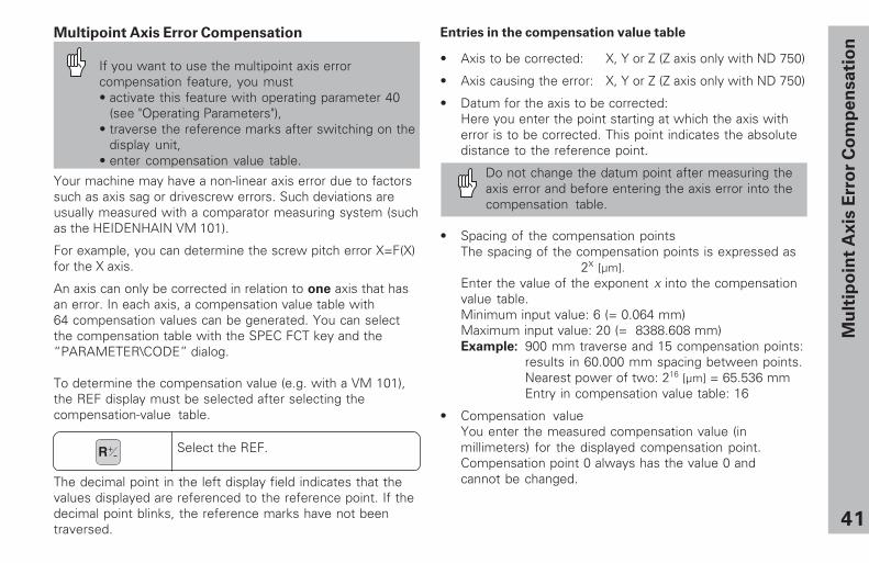
Multipoint Axis Error Compensation
If you want to use the multipoint axis errorcompensation feature, you must• activate this feature with operating parameter 40
(see "Operating Parameters"),• traverse the reference marks after switching on the
display unit,• enter compensation value table.
Entries in the compensation value table
• Axis to be corrected: X, Y or Z (Z axis only with ND 750)
• Axis causing the error: X, Y or Z (Z axis only with ND 750)
• Datum for the axis to be corrected:Here you enter the point starting at which the axis witherror is to be corrected. This point indicates the absolutedistance to the reference point.
Do not change the datum point after measuring theaxis error and before entering the axis error into thecompensation table.
• Spacing of the compensation pointsThe spacing of the compensation points is expressed as
2x [µm].Enter the value of the exponent x into the compensationvalue table.Minimum input value: 6 (= 0.064 mm)Maximum input value: 20 (= 8388.608 mm)Example: 900 mm traverse and 15 compensation points:
results in 60.000 mm spacing between points.Nearest power of two: 216 [µm] = 65.536 mmEntry in compensation value table: 16
• Compensation valueYou enter the measured compensation value (inmillimeters) for the displayed compensation point.Compensation point 0 always has the value 0 andcannot be changed.
Mu
ltip
oin
t A
xis
Err
or
Co
mp
en
sa
tio
n
Your machine may have a non-linear axis error due to factorssuch as axis sag or drivescrew errors. Such deviations areusually measured with a comparator measuring system (suchas the HEIDENHAIN VM 101).
For example, you can determine the screw pitch error X=F(X)for the X axis.
An axis can only be corrected in relation to one axis that hasan error. In each axis, a compensation value table with64 compensation values can be generated. You can selectthe compensation table with the SPEC FCT key and the“ PARAMETER\CODE” dialog.
To determine the compensation value (e.g. with a VM 101),the REF display must be selected after selecting thecompensation-value table.
Select the REF.R+-
The decimal point in the left display field indicates that thevalues displayed are referenced to the reference point. If thedecimal point blinks, the reference marks have not beentraversed.
42
Mu
ltip
oin
t A
xis
Err
or
Co
mp
en
sa
tio
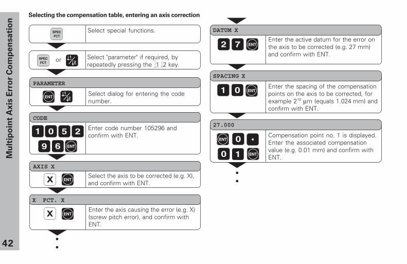
nSelecting the compensation table, entering an axis correction
DATUM X
Enter the active datum for the error onthe axis to be corrected (e.g. 27 mm)and confirm with ENT.
2 7
SPACING X
Enter the spacing of the compensationpoints on the axis to be corrected, forexample 210 µm (equals 1.024 mm) andconfirm with ENT.
1 0
27.000
Compensation point no. 1 is displayed.Enter the associated compensationvalue (e.g. 0.01 mm) and confirm withENT.
0
0 1
Select special functions.
PARAMETER
Select dialog for entering the codenumber.
CODE
Enter code number 105296 andconfirm with ENT.1 0 5 2
9 6 ENT
X
AXIS X
Select the axis to be corrected (e.g. X),and confirm with ENT.
X FCT. X
Enter the axis causing the error (e.g. X)(screw pitch error), and confirm withENT.
••
X
SPECFCT
ENT
ENT
ENT
ENT
ENT
ENT
Select "parameter" if required, byrepeatedly pressing the 1 2 key.
SPECFCT
ENT
or
••

43
Mu
ltip
oin
t A
xis
Err
or
Co
mp
en
sa
tio
n
Z
AXIS X
Select the compensation value table(e.g., for the Z axis), and delete the table.
DELETE Z
Confirm with ENT, or cancel with CL.ENT
Conclude entry.
Deleting a compensation value table
Select special functions.
PARAMETER
Select the dialog for entering the codenumber.
CODE
Enter the code number 105296 andconfirm with ENT.1 0 5 2
9 6 ENT
SPECFCT
Select “ parameter.”SPECFCT
ENT
SPECFCT
or
28.024
Enter all further compensation points. Ifyou press the minus key, the unit willshow the number of the currentcompensation point in the X display.Direct selection of compensationpoints: Press the minus key togetherwith the number (two-digit) of thedesired compensation point.
Conclude entry.
ENT
SPECFCT
or CL

44
Specifications
Housing ND 710/ND 750Bench-top design, cast-metal housingDimensions (W • H • D)270 mm • 172 mm • 93 mm
Oper. temperature 0° to 45° C (32° to 113° F)
Storage temperature – 20° to 70° C (– 4° to 158° F)
Weight Approx. 2.3 kg (5 lb)
Relative humidity <75% annual average<90% in rare cases
Power supply 100 Vac to 240 Vac (−15% to +10%)50 Hz to 60 Hz (± 2 Hz)
Power consumption 15 W
Protection IP 40 as per IEC 529
Encoder inputs For encoders with 7 to 16 µAPPGrating period 2, 4, 10, 20, 40,100, and 200 µmReference mark evaluation fordistance-coded and singlereference marks
Input frequency Max. 100 kHz for 30 mcable length
Display step Adjustable(see “ Linear Encoders” )
Datums 2 (nonvolatile)
Functions − Tool radius compensation− Distance-to-go display− Touching off function with tool− Circular & linear hole patterns− Scaling factor
Sp
ecif
icati
on
s

45
Dimensions mm/inches Tilting base
Sp
ecif
icati
on
s
2409.45"
562.
205"
210 ± 0.28.268 ± .008"
15.6"
8.32"
4.5.18"
120
+ 0
.54.
73 +
.02"
38 ± 0.51.5 ± .02"
20°
923.622"
4.5.18"
46341 695-22 · SW246 271-06 · 15 · 12/2000 · F&W · Printed in Germany · Subject to change without notice
HEIDENHAIN (G.B.) Limited200 London Road, Burgess HillWest Sussex RH15 9RD, Great Britain{ (01444) 247711| (01444) 870024
�������� �� �� ������������������� ��� ��������������������������������� ��� ��� �� ������� ��� ��� �� ��� ����� ��� �!� ��� ��
� ��� !"� ��� ��� �� �����"�#"� $%&���' ( ��� ��� �� ����������� ��� ��� �� ��������� �����' (!� ��� ��
���)���***�� ��� ��


![FALCON 7X VQ-BAA 046 - [AVITRADE Belgium -] · falcon 7x vq-baa 046 flight display equipment: 2 primary display units (dpu) 2 multifunction display units (mdu) intergrated flight](https://img.pdfslide.net/doc/110x75/5c3787ce09d3f240598bc38e/falcon-7x-vq-baa-046-avitrade-belgium-falcon-7x-vq-baa-046-flight-display.jpg)