Embed Size (px)
Citation preview

Serial NumberDecal
Model No. NETL14711.0Serial No.Write the serial number in the spaceabove for reference.
CAUTIONRead all precautions and instruc-tions in this manual before usingthis equipment. Save this manualfor future reference.
QUESTIONS?If you have questions, or if there aremissing parts, please contact us:
UKCall: 08457 089 009From Ireland: 053 92 36102Website: www.iconsupport.euE-mail: [email protected]:ICON Health & Fitness, Ltd.c/o HI Group PLC, Express WayWhitwood, West YorkshireWF10 5QJUK
ON THE WEB:www.nordictrackservice.com
USERʼS MANUAL
www.iconeurope.com

TABLE OF CONTENTSWARNING DECAL PLACEMENT . . . . . . . . . . . . . . . . . . . . . . . . . . . . . . . . . . . . . . . . . . . . . . . . . . . . . . . . . . . . . .2IMPORTANT PRECAUTIONS . . . . . . . . . . . . . . . . . . . . . . . . . . . . . . . . . . . . . . . . . . . . . . . . . . . . . . . . . . . . . . . .3BEFORE YOU BEGIN . . . . . . . . . . . . . . . . . . . . . . . . . . . . . . . . . . . . . . . . . . . . . . . . . . . . . . . . . . . . . . . . . . . . . .5PART IDENTIFICATION CHART . . . . . . . . . . . . . . . . . . . . . . . . . . . . . . . . . . . . . . . . . . . . . . . . . . . . . . . . . . . . . .6ASSEMBLY . . . . . . . . . . . . . . . . . . . . . . . . . . . . . . . . . . . . . . . . . . . . . . . . . . . . . . . . . . . . . . . . . . . . . . . . . . . . . . .7THE CHEST HEART RATE MONITOR . . . . . . . . . . . . . . . . . . . . . . . . . . . . . . . . . . . . . . . . . . . . . . . . . . . . . . . .15OPERATION AND ADJUSTMENT . . . . . . . . . . . . . . . . . . . . . . . . . . . . . . . . . . . . . . . . . . . . . . . . . . . . . . . . . . . .16HOW TO FOLD AND MOVE THE TREADMILL . . . . . . . . . . . . . . . . . . . . . . . . . . . . . . . . . . . . . . . . . . . . . . . . . .25TROUBLESHOOTING . . . . . . . . . . . . . . . . . . . . . . . . . . . . . . . . . . . . . . . . . . . . . . . . . . . . . . . . . . . . . . . . . . . . .26EXERCISE GUIDELINES . . . . . . . . . . . . . . . . . . . . . . . . . . . . . . . . . . . . . . . . . . . . . . . . . . . . . . . . . . . . . . . . . . .29PART LIST . . . . . . . . . . . . . . . . . . . . . . . . . . . . . . . . . . . . . . . . . . . . . . . . . . . . . . . . . . . . . . . . . . . . . . . . . . . . . .30EXPLODED DRAWING . . . . . . . . . . . . . . . . . . . . . . . . . . . . . . . . . . . . . . . . . . . . . . . . . . . . . . . . . . . . . . . . . . . .32ORDERING REPLACEMENT PARTS . . . . . . . . . . . . . . . . . . . . . . . . . . . . . . . . . . . . . . . . . . . . . . . . . .Back CoverRECYCLING INFORMATION . . . . . . . . . . . . . . . . . . . . . . . . . . . . . . . . . . . . . . . . . . . . . . . . . . . . . . . . .Back Cover
This drawing shows the locations of the warningdecals. If a decal is missing or illegible, callthe telephone number on the front cover ofthis manual and request a free replacementdecal. Apply the decal in the location shown.Note: The decals may not be shown at actualsize.
WARNING DECAL PLACEMENT
2NORDICTRACK is a registered trademark of ICON IP, Inc.

3
1. Before beginning any exercise program, con-sult your physician. This is especially impor-tant for persons over age 35 or persons withpre-existing health problems.
2. It is the responsibility of the owner to ensurethat all users of this treadmill are adequatelyinformed of all warnings and precautions.
3. Use the treadmill only as described.
4. Keep the treadmill indoors, away from mois-ture and dust. Do not put the treadmill in agarage or covered patio, or near water.
5. Place the treadmill on a level surface, with atleast 8 ft. (2.4 m) of clearance behind it and 2ft. (0.6 m) on each side. Do not place thetreadmill on any surface that blocks air open-ings. To protect the floor or carpet from dam-age, place a mat under the treadmill.
6. Do not operate the treadmill where aerosolproducts are used or where oxygen is beingadministered.
7. Keep children under age 12 and pets awayfrom the treadmill at all times.
8. The treadmill should be used only by personsweighing 350 lbs. (159 kg) or less.
9. Never allow more than one person on thetreadmill at a time.
10. Wear appropriate exercise clothes whileusing the treadmill. Do not wear loose clothesthat could become caught in the treadmill.Athletic support clothes are recommendedfor both men and women. Always wear ath-letic shoes. Never use the treadmill with barefeet, wearing only stockings, or in sandals.
11. When connecting the power cord (see page16), plug the power cord into an earthed cir-cuit. No other appliance should be on thesame circuit. When replacing the fuse in thepower cord adapter, insert an ASTA-approvedBS1362, 13-amp fuse into the fuse carrier.
12. If an extension cord is needed, use only a 3-conductor, 14-gauge (1 mm2) cord that is nolonger than 5 ft. (1.5 m).
13. Keep the power cord away from heated sur-faces.
14. Never move the walking belt while the poweris turned off. Do not operate the treadmill ifthe power cord or plug is damaged, or if thetreadmill is not working properly. (See TROU-BLESHOOTING on page 26 if the treadmill isnot working properly.)
15. Read, understand, and test the emergencystop procedure before using the treadmill (seeHOW TO TURN ON THE POWER on page 18).
16. Never start the treadmill while you are stand-ing on the walking belt. Always hold thehandrails while using the treadmill.
17. The treadmill is capable of high speeds.Adjust the speed in small increments to avoidsudden jumps in speed.
18. The heart rate monitor is not a medical de-vice. Various factors, including the user'smovement, may affect the accuracy of heartrate readings. The heart rate monitor is in-tended only as an exercise aid in determiningheart rate trends in general.
WARNING: To reduce the risk of serious injury, read all important precautions and in-structions in this manual and all warnings on your treadmill before using your treadmill. ICON as-sumes no responsibility for personal injury or property damage sustained by or through the use ofthis product.
IMPORTANT PRECAUTIONS

4
19. Never leave the treadmill unattended while itis running. Always remove the key, unplugthe power cord, and press the power switchinto the off position when the treadmill is notin use. (See the drawing on page 5 for the lo-cation of the power switch.)
20. Do not attempt to raise, lower, or move thetreadmill until it is properly assembled. (SeeASSEMBLY on page 7, and HOW TO FOLDAND MOVE THE TREADMILL on page 25.)You must be able to safely lift 45 lbs. (20 kg)to raise, lower, or move the treadmill.
21. When folding or moving the treadmill, makesure that the storage latch is holding theframe securely in the storage position.
22. Never insert any object into any opening onthe treadmill.
23. Inspect and properly tighten all parts of thetreadmill regularly.
24. DANGER: Always unplug the powercord immediately after use, before cleaning thetreadmill, and before performing the mainte-nance and adjustment procedures described inthis manual. Never remove the motor hood un-less instructed to do so by an authorized ser-vice representative. Servicing other than theprocedures in this manual should be performedby an authorized service representative only.
25. This treadmill is intended for home use only.Do not use this treadmill in a commercial,rental, or institutional setting.
26. Over exercising may result in serious injuryor death. If you feel faint or if you experiencepain while exercising, stop immediately andcool down.
SAVE THESE INSTRUCTIONS

5
Thank you for selecting the revolutionaryNORDICTRACK® T15.0 treadmill. The T15.0 treadmilloffers an impressive selection of features designed tomake your workouts at home more enjoyable and ef-fective. And when youʼre not exercising, the uniquetreadmill can be folded up, requiring less than half thefloor space of other treadmills.
For your benefit, read this manual carefully beforeusing the treadmill. If you have questions after read-
ing this manual, please see the front cover of this man-ual. To help us assist you, please note the productmodel number and serial number before contacting us.The model number and the location of the serial num-ber decal are shown on the front cover of this manual.
Before reading further, please review the drawingbelow and familiarize yourself with the labeled parts.
BEFORE YOU BEGIN
Handrail
Upright
Tray
Key/Clip
Power SwitchWalking Belt
Platform Cushion
Foot Rail
Power Cord
Idler RollerAdjustment Screws
Console
Handgrip HeartRate Monitor
Length: 6 ft. 10 in. (208 cm)Width: 3 ft. 1 in. (94 cm)

6
#8 x 3/4" Screw(2)–6
3/8" StarWasher (13)–4
3/8" Nut (12)–25/16" StarWasher (11)–8
#10 x 3/4" Screw(9)–4
3/8" x 2 3/4" Screw (7)–4
3/8" x 1 3/4" Bolt (6)–1
3/8" x 2" Bolt (3)–1
5/16" x 1"Screw (5)–4
#8 x 1/2" GroundScrew (10)–1
#8 x 1/2" Screw(1)–6
5/16" x 1 1/4"Bolt (4)–6 3/8" x 1 1/4"
Screw (8)–4
#8 x 1" Screw(25)–4
PART IDENTIFICATION CHARTUse the drawings below to identify small parts used for assembly. The number in parentheses below each draw-ing is the key number of the part, from the PART LIST near the end of this manual. The number following the keynumber is the quantity used for assembly. Note: If a part is not in the hardware kit, check to see if it is preat-tached. Extra hardware may be included.

7
1. Make sure that the power cord is unplugged.
Place a piece of cardboard below the rear of theFrame (56) to protect the floor or carpet.
Attach the Left Wheel Cap (96) to the Base (94)with two #8 x 3/4" Screws (2).
Attach the Right Wheel Cap (not shown) tothe right side of the Base (94) in the sameway.
1
96
94
2
56
Cardboard
2. Pull the Upright Wire (81) and the Base GroundWire (28) through the indicated hole in the Base(94).
Attach the Base Ground Wire (28) to the Base(94) with a #8 x 1/2" Ground Screw (10).
Press the Grommet (77) into the square hole inthe Base (94). 81
2
Hole
10 2894
77
ASSEMBLY
• Assembly requires two persons.
• Place all parts in a cleared area and remove thepacking materials. Do not dispose of the packingmaterials until you finish assembly.
• The underside of the walking belt is coated withhigh-performance lubricant. After shipping, theremay be some lubricant on top of the walking beltor on the shipping carton. This is normal. If thereis lubricant on top of the walking belt, wipe it offwith a soft cloth and a mild, non-abrasive cleaner.
• To identify small parts, see page 6.
• Assembly requires the following tools:
the included hex keys
one adjustable wrench
one Phillips screwdriver
To avoid damaging parts, do not use power toolsfor assembly.

8
4. Hold the Left Upright (89) against the Base(94). Be careful not to pinch any wires. Inserttwo 3/8" x 2 3/4" Screws (7) and two 3/8" x 11/4" Screws (8) with two 3/8" Star Washers (13)into the Left Upright.
Partially tighten the 3/8" x 2 3/4" Screws (7) andthe 3/8" x 1 1/4" Screws (8) until the heads ofthe Screws touch the Left Upright (89); do notfully tighten the Screws yet.
Attach the Right Upright (not shown) in thesame way. Note: There are no wires on theright side.
89
94
4
8
7
13
13
3. Identify the Left Upright (89), which is marked“Left.” Have a second person hold the LeftUpright near the Base (94).
See the inset drawing. Tie the wire tie in theLeft Upright (89) securely around the end of theUpright Wire (81). Then, pull the other end of thewire tie until the Upright Wire is routed throughthe Left Upright.
81
3
81
89
WireTie
WireTie
89
9481

9
6. Identify the Left Handrail (88), and hold it nearthe Left Upright (89).
Tie the wire tie in the Left Handrail (88) securelyaround the end of the Upright Wire (81). Then,pull the other end of the wire tie until the UprightWire is routed through the Left Handrail. Makesure that the Upright Wire is on the left sideof the indicated bracket.
88
6
89
81
WireTie
Bracket
5. Identify the Left and Right Base Covers (82, 83).Slide the Left Base Cover onto the Left Upright(89). Slide the Right Base Cover onto the RightUpright (90). Do not press the Base Coversinto place yet.
Remove the wire tie from the Upright Wire (81).
89
82
90
83
5
WireTie
81

10
8. Set the console assembly face down on a softsurface to avoid scratching the consoleassembly.
Remove the four Screws (A). Next, lift off theCrossbar (93) and the Console Frame (104).Discard the four Screws.
93
ConsoleAssembly
A
8A
A
104
7. Attach the Left Handrail (88) to the Left Upright(89) with two 5/16" x 1" Screws (5), two 5/16"Star Washers (11), and a 5/16" x 1 1/4" Bolt (4).Do not tighten the Bolt and Screws yet.
Attach the Right Handrail (87) in the sameway.
Slide the Upright Wire (81) to the right side ofthe indicated bracket. Be careful not to pinchthe Upright Wire between the Left OutsideHandrail Cover (80) and the bracket.
7
89
88
87
4
4
55
80
11
11
81Bracket

11
10. Attach the Console Frame (104) to theHandrails (87, 88) with four 5/16" x 1 1/4" Bolts(4) and four 5/16" Star Washers (11). Start allfour Bolts, and then tighten them.
10 104
87
88
411
411
9. IMPORTANT: To avoid damaging theCrossbar (93), do not use power tools anddo not overtighten the #10 x 3/4" Screws (9).
Orient the Crossbar (93) as shown. Tighten allfour #10 x 3/4" Screws (9) about halfway intothe Handrails (87, 88). Slide the Crossbar as farforward as possible and tighten the four Screws.
93
88
9
9 9
87

12
12. Set the console assembly on the Left and RightHandrails (88, 87). Be careful not to pinch anywires. Insert the excess Upright Wire (notshown) into the Left Handrail.
Attach the console assembly with six #8 x 1/2"Screws (1) and two #8 x 3/4" Screws (2) (onlyone side is shown). Start all eight Screws, andthen tighten each of them.
Attach two Console Clamps (106) to the consoleassembly with four #8 x 1" Screws (25).
See step 7. Fully tighten the four 5/16" x 1"Screws (5) and the two 5/16" x 1 1/4" Bolts (4).
881
12Console
Assembly
187
225 25
106106
11. With the help of a second person, hold the con-sole assembly near the Left Handrail (88).
Connect the Upright Wire (81) to the consolewire. See the inset drawing. The connectorsshould slide together easily and snap intoplace. If they do not, turn one connector and tryagain. IF YOU DO NOT CONNECT THE CON-NECTORS PROPERLY, THE CONSOLE MAYBECOME DAMAGED WHEN YOU TURN ONTHE POWER. Then, remove the wire tie fromthe Upright Wire.
Connect the ground wire from the console as-sembly to the Console Ground Wire (105) andinsert the wires into the hole in the consoleassembly.
ConsoleAssembly
ConsoleWire
WireTie
88
81
81
ConsoleWire
11
GroundWire105
Hole

13
14. Raise the Frame (56) to the position shown.Have a second person hold the Frame untilstep 15 is completed.
Orient the Storage Latch (53) so that the largebarrel and the latch knob are in the positionsshown.
Attach the lower end of the Storage Latch (53) tothe Base (94) with a 3/8" x 2" Bolt (3) and a 3/8"Nut (12).
14
53
LargeBarrel
LatchKnob
12 394
13. Firmly tighten the four 3/8" x 2 3/4" Screws (7),and then tighten the four 3/8" x 1 1/4" Screws(8) (only one side is shown).
Press the Left and Right Base Covers (82, 83)onto the Base (94) until they snap into place.
13
83
8
82
94
7
56
14
16. Make sure that all parts are properly tightened before you use the treadmill. If there are sheets of plasticon the treadmill decals, remove the plastic. To protect the floor or carpet, place a mat under the treadmill.Note: Extra hardware may be included. Keep the included hex keys in a secure place; one of the hex keys isused to adjust the walking belt (see pages 27 and 28).
15. Attach the upper end of the Storage Latch (53)to the Frame (56) with a 3/8" x 1 3/4" Bolt (6)and a 3/8" Nut (12). Note: It may be necessaryto move the Frame (56) back and forth to alignthe Storage Latch with the Frame.
Lower the Frame (56) (see HOW TO LOWERTHE TREADMILL FOR USE on page 25).
15
53
12
56
6

15
HOW TO PUT ON THE HEART RATE MONITOR
The heart ratemonitor consists ofa chest strap and asensor. Insert thetab on one end ofthe chest strap intothe hole in one endof the sensor asshown. Then, pressthe end of the sen-sor under the buckleon the chest strap.The tab should beflush with the frontof the sensor.
The heart rate moni-tor must be wornunder your clothes,tight against yourskin. Wrap the heartrate monitor aroundyour chest in the lo-cation shown. Makesure that the logo isright-side-up. Then,attach the other end of the chest strap to the sensor.Adjust the length of the chest strap, if necessary.
Pull the sensor away from your body a few inches andlocate the two electrode areas, which are covered byshallow ridges. Using saline solution such as saliva orcontact lens solution, wet the electrode areas. Then,return the sensor to a position against your chest.
CARE AND MAINTENANCE
• Thoroughly dry the sensor with a soft towel aftereach use. Moisture may keep the sensor activated,shortening the life of the battery.
• Store the heart rate monitor in a warm, dry place.Do not store the heart rate monitor in a plastic bagor other container that may trap moisture.
• Do not expose the heart rate monitor to directsunlight for extended periods of time; do not exposeit to temperatures above 122° F (50° C) or below 14°F (-10° C).
• Do not excessively bend or stretch the sensor whenusing or storing the heart rate monitor.
• To clean the sensor, use a damp cloth and a smallamount of mild soap. Then, wipe the sensor with adamp cloth and thoroughly dry it with a soft towel.Never use alcohol, abrasives, or chemicals to cleanthe sensor. Hand wash and air dry the chest strap.
TROUBLESHOOTING
If the heart rate monitor does not function properly, trythe steps below.
• Make sure that you are wearing the heart rate moni-tor as described at the left. If the heart rate monitordoes not function when positioned as described,move it slightly lower or higher on your chest.
• If heart rate readings are not displayed until youbegin perspiring, rewet the electrode areas.
• For the console to display heart rate readings, youmust be within armʼs length of the console.
• If there is a battery cover on the back of the sensor,replace the battery with a new battery of the sametype.
• The heart rate monitor is designed to work withpeople who have normal heart rhythms. Heart ratereading problems may be caused by medicalconditions such as premature ventricular contrac-tions (pvcs), tachycardia bursts, and arrhythmia.
• The operation of the heart rate monitor can beaffected by magnetic interference from high powerlines or other sources. If you suspect that magneticinterference is causing a problem, try relocating thefitness equipment.
THE CHEST HEART RATE MONITOR
Tab
Sensor Buckle
ChestStrapTabs
Sensor

16
HOW TO PLUG IN THE POWER CORD
This product must be earthed. If it should malfunc-tion or break down, earthing provides a path of leastresistance for electric current to reduce the risk of elec-tric shock. This productʼs power cord has an equip-ment-earthing conductor and an earthing plug.IMPORTANT: If the power cord is damaged, it mustbe replaced with a manufacturer-recommendedpower cord.
Follow the steps below to plug in the power cord.
1. Plug the indicated end of the power cord into thesocket on the treadmill.
2. Plug the power cord into an appropriate outlet thatis properly installed and earthed in accordance withall local codes and ordinances.
DANGER: Improper connection ofthe equipment-earthing conductor can resultin an increased risk of electric shock. Checkwith a qualified electrician or serviceman ifyou are in doubt as to whether the product isproperly earthed. Do not modify the plug pro-vided with the product—if it will not fit theoutlet, have a proper outlet installed by aqualified electrician.
OPERATION AND ADJUSTMENT
Socket on Treadmill
Outlet
UK Australia
Outlet
Power Cord

17
FEATURES OF THE CONSOLE
The treadmill console offers an impressive array offeatures designed to make your workouts more effec-tive and enjoyable. When you use the manual mode,you can change the speed and incline of the treadmillwith the touch of a button. As you exercise, the con-sole will display instant exercise feedback. You caneven measure your heart rate using the handgrip heartrate monitor or the chest heart rate monitor.
In addition, the console features twenty onboard work-outs—five calorie workouts, five intensity workouts,five speed workouts, and five incline workouts. Eachworkout automatically controls the speed and incline ofthe treadmill as it guides you through an effective exer-cise session.
The console also features an iFit Live mode that en-ables the treadmill to communicate with your wirelessnetwork through an optional iFit Live module. With theiFit Live mode, you can download personalized work-outs, create your own workouts, track your workout re-sults, race against other runners, and access manyother features. To purchase an iFit Live module atany time, go to www.iFit.com or call the telephonenumber on the front cover of this manual.
You can even listen to your favorite workout music oraudio books with the consoleʼs stereo sound systemwhile you exercise.
To turn on the power, see page 18. To use the man-ual mode, see page 18. To use an onboard work-out, see page 21. To use an iFit Live workout, seepage 22. To use the stereo sound system, see page23. To use the information mode, see page 24.
Note: The console can display speed and distance ineither miles or kilometers. To find which unit of mea-surement is selected, see THE INFORMATION MODEon page 24. For simplicity, all instructions in this man-ual refer to kilometers.
IMPORTANT: If there are sheets of plastic on theconsole, remove the plastic. To prevent damage tothe walking platform, wear clean athletic shoeswhile using the treadmill. The first time you use thetreadmill, observe the alignment of the walkingbelt, and center the walking belt if necessary (seepage 28).
CONSOLE DIAGRAM

18
HOW TO TURN ON THE POWER
IMPORTANT: If the treadmill has been exposed tocold temperatures, allow it to warm to room tem-perature before you turn on the power. If you donot do this, you may damage the console displaysor other electrical components.
Plug in the power cord (seepage 16). Next, locate thepower switch on the tread-mill frame near the powercord. Press the powerswitch into the resetposition.
IMPORTANT: The console features a display demomode, designed to be used if the treadmill is dis-played in a store. If the displays light as soon asyou plug in the power cord and press the powerswitch into the reset position, the demo mode isturned on. To turn off the demo mode, hold downthe Stop button for a few seconds. If the displaysremain lit, see THE INFORMATION MODE on page24 to turn off the demo mode.
Next, stand on the foot railsof the treadmill. Find theclip attached to the key andslide the clip onto the waist-band of your clothes. Then,insert the key into the con-sole. After a moment, thedisplays will light.IMPORTANT: In an emergency, the key can bepulled from the console, causing the walking beltto slow to a stop. Test the clip by carefully taking afew steps backward; if the key is not pulled fromthe console, adjust the position of the clip.
HOW TO USE THE MANUAL MODE
1. Insert the key into the console.
See HOW TO TURN ON THE POWER at the left.
2. Select the manual mode.
Press the Manual button on the console. If you arenot connected to iFit Live, the manual mode will beselected automatically.
3. Start the walking belt.
To start the walking belt, press the Start button, theSpeed increase button, or one of the 1 Step Speedbuttons numbered 2 through 22.
If you press the Start button or the Speed increasebutton, the walking belt will begin to move at 2Km/H. As you exercise, change the speed of thewalking belt as desired by pressing the Speed in-crease and decrease buttons. Each time you pressone of the buttons, the speed setting will change by0.1 Km/H; if you hold down the button, the speedsetting will change in increments of 0.5 Km/H.Note: After you press the button, it may take a mo-ment for the walking belt to reach the selectedspeed setting.
If you press one of the numbered 1 Step Speedbuttons, the walking belt will gradually changespeed until it reaches the selected speed setting.
To stop the walking belt, press the Stop button.The time will begin to flash in the display. To restartthe walking belt, press the Start button or theSpeed increase button.
Reset
Key
Clip
19
4. Change the incline of the treadmill as desired.
To change the incline of the treadmill, press theIncline increase or decrease button or one of thenumbered 1 Step Incline buttons. Each time youpress one of the buttons, the treadmill will gradu-ally adjust to the selected incline setting.
5. Follow your progress with the displays.
As you walk or run on the treadmill, the display canshow the following workout information:
• The elapsed time
• The distance that you have walked or run
• The workout intensity bar
• The approximate number of calories you haveburned
• The incline level of the treadmill
• The number of vertical feet you have climbed
• The speed of the walking belt
• Your heart rate (see step 6 on page 20)
• The matrix
The matrix offers several display tabs. Press theincrease and decrease button next to the Enterbutton until the desired tab is shown.
The Incline tab will show a profile of the incline set-tings of the workout. A new segment will appear atthe end of each minute. The Speed tab will show aprofile of the speed settings of the workout.
The My Trail tab will show a track that represents400 meters (1/4 mile). As you exercise, the whiterectangle will show your progress. The My Trail tabwill also show the number of laps you complete.
The Calorie tab will show the approximate amountof calories you have burned. The height of eachsegment represents the amount of calories burnedduring that segment. When the Calorie tab is se-lected, the calorie display will show the approxi-mate number of calories burned per hour.
As you exercise, the workout intensity level bar willindicate the approximate intensity level of yourexercise.
Press the Home button to return to the defaultmenu (see THE INFORMATION MODE on page24 to set the default menu). If necessary, press theHome button again.
When an iFit Live module isconnected, the wireless sym-bol at the top of the displaywill show the strength of yourwireless signal. Four arcs in-dicate full signal strength.
To reset the displays, press the Stop button, re-move the key, and then reinsert the key.

20
6. Measure your heart rate if desired.
Note: If you use the handgrip heart rate monitorand the chest heart rate monitor at the sametime, the console will not display your heartrate accurately. For information about the chestheart rate monitor, see page 15.
Before using thehandgrip heartrate monitor, re-move the sheetsof plastic fromthe metal con-tacts on thepulse bar. In ad-dition, make surethat your handsare clean.
7. Turn on the fan if desired.
The fan features multiple speed settings and anauto mode. When the auto mode is selected, thespeed of the fan will automatically increase and de-crease as the speed of the walking belt increasesand decreases.
Press the Manual fanbutton to select a fanspeed or to turn off thefan. Press the Auto fanbutton to select the automode or to turn off thefan.
If the fan is on when the walking belt is stopped,the fan will turn off automatically after a fewminutes.
8. When you are finished exercising, remove thekey from the console.
Step onto the foot rails, press the Stop button, andadjust the incline of the treadmill to the lowestsetting. The incline must be at the lowest set-ting or you may damage the treadmill when youfold it to the storage position. Next, remove thekey from the console and put it in a secure place.
When you are finished using the treadmill, pressthe power switch into the off position and unplugthe power cord. IMPORTANT: If you do not dothis, the treadmillʼs electrical components maywear prematurely.
Contacts

21
HOW TO USE AN ONBOARD WORKOUT
1. Insert the key into the console.
See HOW TO TURN ON THE POWER on page 18.
2. Select an onboard workout.
To select an onboard workout, press the Caloriebutton, the Intensity button, the Speed button, orthe Incline button repeatedly until the desired work-out appears in the display.
When you select an onboard workout, the displaywill show the duration of the workout and the nameof the workout. In addition, a profile of the speedsettings of the workout will appear in the matrix. Ifyou select a calorie workout, the approximate num-ber of calories you will burn will appear in the nameof the workout.
3. Start the workout.
Press the Start button or the Speed increase buttonto start the workout. A moment after you press thebutton, the treadmill will automatically adjust to thefirst speed and incline settings of the workout. Holdthe handrails and begin walking.
Each workout is divided into segments. One speedsetting and one incline setting are programmed foreach segment. Note: The same speed settingand/or incline setting may be programmed for con-secutive segments.
During theworkout, theprofiles onthe speedand inclinetabs willshow your
progress. The flashing segment of the profile repre-sents the current segment of the workout. Theheight of the flashing segment indicates the speedor incline setting for the current segment. At theend of each segment, a series of tones will soundand the next segment of the profile will begin toflash. If a different speed and/or incline setting isprogrammed for the next segment, the speedand/or incline setting will flash in the display to alertyou and the treadmill will automatically adjust to thenew speed and/or incline setting.
The workout will continue in this way until the lastsegment of the profile flashes in the display and thelast segment ends. The walking belt will then slowto a stop.
Note: The calorie goal is an estimate of thenumber of calories that you will burn during theworkout. The actual number of calories that youburn will depend on your weight. In addition, ifyou manually change the speed or incline ofthe treadmill during the workout, the number ofcalories you burn will be affected.
If the speed or incline setting is too high or too lowat any time during the workout, you can manuallyoverride the setting by pressing the Speed orIncline buttons; however, when the next segmentof the workout begins, the treadmill will auto-matically adjust to the speed and incline set-tings for the next segment.
To stop the workout at any time, press the Stopbutton. The time will begin to flash in the display.To resume the workout, press the Start button orthe Speed increase button. The walking belt willbegin to move at 2 Km/H. When the next segmentof the workout begins, the treadmill will automati-cally adjust to the speed and incline settings for thenext segment.Current Segment

22
4. Follow your progress with the displays.
See step 5 on page 19. If you select an onboardworkout, the display will show the time remaininginstead of the elapsed time.
5. Measure your heart rate if desired.
See step 6 on page 20.
6. Turn on the fan if desired.
See step 7 on page 20.
7. When you are finished exercising, remove thekey from the console.
See step 8 on page 20.
HOW TO USE AN IFIT LIVE WORKOUT
Note: To use an iFit Live workout, you must have anoptional iFit Live module. To purchase an iFit Livemodule at any time, go to www.iFit.com or call thetelephone number on the front cover of this man-ual. You must also have access to a computer with aUSB port and an internet connection. In addition, youmust have access to a wireless network including an802.11b router with SSID broadcast enabled (hiddennetworks are not supported). An iFit.com membershipis also required.
1. Insert the key into the console.
See HOW TO TURN ON THE POWER on page 18.
2. Insert the iFit Live module into the console.
To insert the iFit Live module, see the instructionsincluded with the iFit Live module.
IMPORTANT: To satisfy exposure compliancerequirements, the antenna and transmitter inthe iFit Live module must be at least 8 in. (20 cm)from all persons and must not be near or con-nected to any other antenna or transmitter.
3. Select a user.
If more than one user is registered, you can switchusers in the iFit Live main screen. Press the in-crease and decrease buttons next to the Enter but-ton to select a user.
4. Select an iFit Live workout.
To select an iFit Live workout, press one of the iFitLive buttons. Before some workouts will download,you must add them to your schedule onwww.iFit.com.
Press the iFit Live button to download the nextworkout in your schedule. Press the My Trainerbutton, the My Maps button, the World Tour button,or the Event Training button to download the nextworkout of that type in your schedule. Press theCompete button to compete in a race that you havepreviously scheduled. For more informationabout the iFit Live workouts, please seewww.iFit.com. Note: If there are no workouts ofthe selected type in your schedule, the next work-out in your schedule will be downloaded.

23
When you select an iFit Live workout, the displaywill show the duration of the workout, the distanceyou will walk or run, and the approximate number ofcalories you will burn. The display may also showthe name of the workout. If you select a competitionworkout, the display will count down to the begin-ning of the race.
Note: Each iFit Live button can also run two demoworkouts. To use the demo workouts, remove theiFit Live module from the console and press one ofthe iFit Live buttons.
5. Start the workout.
See step 3 on page 21.
During some workouts, the voice of a personaltrainer will guide you through your workout. Youcan select an audio setting for your personal trainer(see THE INFORMATION MODE on page 24).
To stop the workout at any time, press the Stopbutton. The time will begin to flash in the display.To resume the workout, press the Start button orthe Speed increase button. The walking belt willbegin to move at the speed setting for the first seg-ment of the workout. When the next segment of theworkout begins, the treadmill will automatically ad-just to the speed and incline settings for the nextsegment.
6. Follow your progress with the displays.
See step 5 on page 19.
The My Trail tab will show a map of the trail youare walking or running or it will show a track andthe number of laps you complete.
During a competition workout, the Competition tabwill show your progress in the race. As you race,the top line in the matrix will show how much of therace you have completed. The other lines will showyour top four competitors. The end of the matrixrepresents the end of the race.
7. Measure your heart rate if desired.
See step 6 on page 20.
8. Turn on the fan if desired.
See step 7 on page 20.
9. When you are finished exercising, remove thekey from the console.
See step 8 on page 20.
For more information about the iFit Live mode, goto www.iFit.com.
HOW TO USE THE STEREO SOUND SYSTEM
To play music or audio books through the consoleʼsstereo speakers, you must connect your MP3 player,CD player, or other personal audio player to the con-sole through the audio jack below the speakers.
To use the audio jack, locate the included audio wireand plug it into the audio jack. Then, plug the audiowire into a jack on your MP3 player, CD player, orother personal audio player. Make sure that the audiowire is fully inserted.
Next, press the Play buttonon your MP3 player, CDplayer, or other personalaudio player. Adjust the vol-ume on your personal audioplayer or press the volumeincrease and decrease but-tons on the console.
If you are using a personal CD player and the CDskips, set the CD player on the floor or another flat sur-face instead of on the console.
Volume Increase
Volume Decrease
24
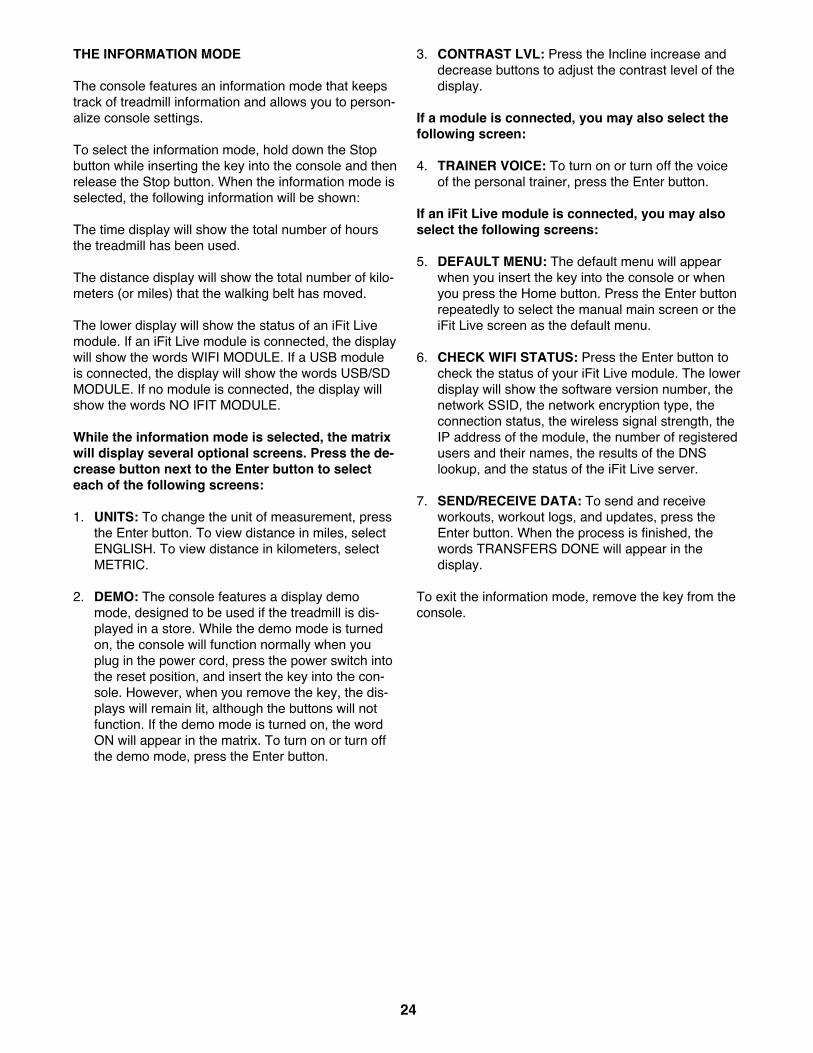
THE INFORMATION MODE
The console features an information mode that keepstrack of treadmill information and allows you to person-alize console settings.
To select the information mode, hold down the Stopbutton while inserting the key into the console and thenrelease the Stop button. When the information mode isselected, the following information will be shown:
The time display will show the total number of hoursthe treadmill has been used.
The distance display will show the total number of kilo-meters (or miles) that the walking belt has moved.
The lower display will show the status of an iFit Livemodule. If an iFit Live module is connected, the displaywill show the words WIFI MODULE. If a USB moduleis connected, the display will show the words USB/SDMODULE. If no module is connected, the display willshow the words NO IFIT MODULE.
While the information mode is selected, the matrixwill display several optional screens. Press the de-crease button next to the Enter button to selecteach of the following screens:
1. UNITS: To change the unit of measurement, pressthe Enter button. To view distance in miles, selectENGLISH. To view distance in kilometers, selectMETRIC.
2. DEMO: The console features a display demomode, designed to be used if the treadmill is dis-played in a store. While the demo mode is turnedon, the console will function normally when youplug in the power cord, press the power switch intothe reset position, and insert the key into the con-sole. However, when you remove the key, the dis-plays will remain lit, although the buttons will notfunction. If the demo mode is turned on, the wordON will appear in the matrix. To turn on or turn offthe demo mode, press the Enter button.
3. CONTRAST LVL: Press the Incline increase anddecrease buttons to adjust the contrast level of thedisplay.
If a module is connected, you may also select thefollowing screen:
4. TRAINER VOICE: To turn on or turn off the voiceof the personal trainer, press the Enter button.
If an iFit Live module is connected, you may alsoselect the following screens:
5. DEFAULT MENU: The default menu will appearwhen you insert the key into the console or whenyou press the Home button. Press the Enter buttonrepeatedly to select the manual main screen or theiFit Live screen as the default menu.
6. CHECK WIFI STATUS: Press the Enter button tocheck the status of your iFit Live module. The lowerdisplay will show the software version number, thenetwork SSID, the network encryption type, theconnection status, the wireless signal strength, theIP address of the module, the number of registeredusers and their names, the results of the DNSlookup, and the status of the iFit Live server.
7. SEND/RECEIVE DATA: To send and receiveworkouts, workout logs, and updates, press theEnter button. When the process is finished, thewords TRANSFERS DONE will appear in thedisplay.
To exit the information mode, remove the key from theconsole.

25
HOW TO FOLD THE TREADMILL
To avoid damaging the treadmill, adjust the inclineto the lowest position before you fold the treadmill.Then, remove the key and unplug the power cord.CAUTION: You must be able to safely lift 45 lbs. (20kg) to raise, lower, or move the treadmill.
1. Hold the metal frame firmly in the location shownby the arrow below. CAUTION: Do not hold theframe by the plastic foot rails. Bend your legsand keep your back straight.
2. Raise the frame until the latch knob locks in thestorage position. CAUTION: Make sure that thelatch knob locks.
To protect the floor or carpet, place a mat under thetreadmill. Keep the treadmill out of direct sunlight.Do not leave the treadmill in the storage position intemperatures above 85° F (30° C).
HOW TO MOVE THE TREADMILL
Before moving the treadmill, fold it as described at theleft. CAUTION: Make sure that the latch knob islocked in the storage position. Moving the tread-mill may require two people.
1. Hold the frame and one of the handrails, and placeone foot against a wheel.
2. Pull back on the handrail until the treadmill will rollon the wheels, and carefully move it to the desiredlocation. CAUTION: Do not move the treadmillwithout tipping it back, do not pull on the frame,and do not move the treadmill over an unevensurface.
3. Place one foot against a wheel, and carefully lowerthe treadmill.
HOW TO LOWER THE TREADMILL FOR USE
1. See drawing 2. Hold the upper end of the treadmillframe with your right hand. Then, pull the latchknob to the left. IMPORTANT: Do not turn thelatch knob. If necessary, push the frame forwardslightly. Pivot the frame downward a few inches,and release the latch knob.
2. See drawing 1 at the left. Hold the metal framefirmly with both hands, and lower it to the floor.CAUTION: Do not hold the frame by the plasticfoot rails, and do not drop the frame. Bend yourlegs and keep your back straight.
HOW TO FOLD AND MOVE THE TREADMILL
Handrail
Frame
Wheel
Frame
1
1
LatchKnob
2
Frame

26
Most treadmill problems can be solved by followingthe simple steps below. Find the symptom thatapplies, and follow the steps listed. If further assis-tance is needed, see the front cover of this manual.
SYMPTOM: The power does not turn on
a. Make sure that the power cord is plugged into aproperly earthed outlet (see page 16). If an exten-sion cord is needed, use only a 3-conductor, 14-gauge (1 mm2) cord that is no longer than 5 ft. (1.5m).
b. After the power cord has been plugged in, makesure that the key is inserted into the console.
c. Check the power switch located on the treadmillframe near the power cord. If the switch protrudesas shown, the switch has tripped. To reset thepower switch, wait for five minutes and then pressthe switch back in.
SYMPTOM: The power turns off during use
a. Check the power switch (see the drawing above). Ifthe switch has tripped, wait for five minutes andthen press the switch back in.
b. Make sure that the power cord is plugged in. If thepower cord is plugged in, unplug it, wait for fiveminutes, and then plug it back in.
c. Remove the key from the console, and thenreinsert it.
d. If the treadmill still will not run, please see the frontcover of this manual.
SYMPTOM: The console displays remain lit whenyou remove the key from the console
a. The console features a display demo mode, de-signed to be used if the treadmill is displayed in astore. If the displays remain lit when you removethe key, the demo mode is turned on. To turn offthe demo mode, hold down the Stop button for afew seconds. If the displays are still lit, see THEINFORMATION MODE on page 24 to turn off thedemo mode.
SYMPTOM: The displays of the console do notfunction properly
a. Remove the key from the console and UNPLUGTHE POWER CORD. Remove the five #8 x 3/4"Screws (2) and carefully pivot the Motor Hood (65)off.
TROUBLESHOOTING
Tripped Reset
c
652
2
a2

27
Locate the Reed Switch (52) and the Magnet (50)on the left side of the Pulley (49). Turn the Pulleyuntil the Magnet is aligned with the Reed Switch.Make sure that the gap between the Magnetand the Reed Switch is about 1/8 in. (3 mm). Ifnecessary, loosen the #8 x 3/4" Tek Screw (14),move the Reed Switch slightly, and then retightenthe Tek Screw. Then, reattach the Motor Hood (notshown), and run the treadmill for a few minutes tocheck for a correct speed reading.
SYMPTOM: The incline of the treadmill does notchange correctly
a. Hold down the Stop button and the Speed increasebutton, insert the key into the console, and then re-lease the Stop button and the Speed increase but-ton. Next, press the Stop button and then press theIncline increase or decrease button. The treadmillwill automatically rise to the maximum incline leveland then return to the minimum level. This will recal-ibrate the incline system. If the incline system doesnot calibrate, press the Stop button, and then pressthe Incline increase or decrease button again.When the incline system is calibrated, remove thekey from the console.
SYMPTOM: The walking belt slows when walked on
a. If an extension cord is needed, use only a 3-con-ductor, 14-gauge (1 mm2) cord that is no longerthan 5 ft. (1.5 m).
b. If the walking belt is overtightened, treadmill perfor-mance may decrease and the walking belt may be-come damaged. Remove the key and UNPLUGTHE POWER CORD. Using the hex key, turn bothidler roller screws counterclockwise, 1/4 of a turn.When the walking belt is properly tightened, youshould be able to lift each edge of the walking belt2 to 3 in. (5 to 7 cm) off the walking platform. Becareful to keep the walking belt centered. Then,plug in the power cord, insert the key, and run thetreadmill for a few minutes. Repeat until the walk-ing belt is properly tightened.
c. Your treadmill features a walking belt coated withhigh-performance lubricant. IMPORTANT: Neverapply silicone spray or other substances to thewalking belt or the walking platform unless in-structed to do so by an authorized service rep-resentative. Such substances may deterioratethe walking belt and cause excessive wear. Ifyou suspect that the walking belt needs more lubri-cant, see the front cover of this manual.
d. If the walking belt still slows when walked on, seethe front cover of this manual.
TopView
501452
1/8 in.
49
Idler Roller Screws
2–3 in.b

28
SYMPTOM: The walking belt is off-center or slipswhen walked on
a. If the walking belt is off-center, first remove thekey and UNPLUG THE POWER CORD. If thewalking belt has shifted to the left, use the hexkey to turn the left idler roller screw clockwise 1/2of a turn; if the walking belt has shifted to theright, turn the left idler roller screw counterclock-wise 1/2 of a turn. Be careful not to overtighten thewalking belt. Then, plug in the power cord, insertthe key, and run the treadmill for a few minutes.Repeat until the walking belt is centered.
b. If the walking belt slips when walked on, first re-move the key and UNPLUG THE POWER CORD.Using the hex key, turn both idler roller screwsclockwise, 1/4 of a turn. When the walking belt iscorrectly tightened, you should be able to lift eachedge of the walking belt 2 to 3 in. (5 to 7 cm) offthe walking platform. Be careful to keep the walk-ing belt centered. Then, plug in the power cord, in-sert the key, and carefully walk on the treadmill fora few minutes. Repeat until the walking belt isproperly tightened.
SYMPTOM: The console display has lines runningthrough it
a. If lines appear in the console display, see THE IN-FORMATION MODE on page 24 and adjust thecontrast level of the display.
a
b

29
These guidelines will help you to plan your exerciseprogram. For detailed exercise information, obtain areputable book or consult your physician. Remember,proper nutrition and adequate rest are essential forsuccessful results.
EXERCISE INTENSITY
Whether your goal is to burn fat or to strengthen yourcardiovascular system, exercising at the proper inten-sity is the key to achieving results. You can use yourheart rate as a guide to find the proper intensity level.The chart below shows recommended heart rates forfat burning and aerobic exercise.
To find the proper intensity level, find your age at thebottom of the chart (ages are rounded off to the near-est ten years). The three numbers listed above yourage define your “training zone.” The lowest number isthe heart rate for fat burning, the middle number is theheart rate for maximum fat burning, and the highestnumber is the heart rate for aerobic exercise.
Burning Fat—To burn fat effectively, you must exer-cise at a low intensity level for a sustained period oftime. During the first few minutes of exercise, yourbody uses carbohydrate calories for energy. Only afterthe first few minutes of exercise does your body beginto use stored fat calories for energy. If your goal is toburn fat, adjust the intensity of your exercise until yourheart rate is near the lowest number in your trainingzone. For maximum fat burning, exercise with yourheart rate near the middle number in your trainingzone.
Aerobic Exercise—If your goal is to strengthen yourcardiovascular system, you must perform aerobic exer-cise, which is activity that requires large amounts ofoxygen for prolonged periods of time. For aerobic ex-ercise, adjust the intensity of your exercise until yourheart rate is near the highest number in your trainingzone.
WORKOUT GUIDELINES
Warming Up—Start with 5 to 10 minutes of stretchingand light exercise. A warm-up increases your bodytemperature, heart rate, and circulation in preparationfor exercise.
Training Zone Exercise—Exercise for 20 to 30 min-utes with your heart rate in your training zone. (Duringthe first few weeks of your exercise program, do notkeep your heart rate in your training zone for longerthan 20 minutes.) Breathe regularly and deeply as youexercise—never hold your breath.
Cooling Down—Finish with 5 to 10 minutes of stretch-ing. Stretching increases the flexibility of your musclesand helps to prevent post-exercise problems.
EXERCISE FREQUENCY
To maintain or improve your condition, complete threeworkouts each week, with at least one day of rest be-tween workouts. After a few months of regular exer-cise, you may complete up to five workouts eachweek, if desired. Remember, the key to success is tomake exercise a regular and enjoyable part of youreveryday life.
EXERCISE GUIDELINES
WARNING: Before beginning thisor any exercise program, consult your physi-cian. This is especially important for personsover age 35 or persons with pre-existinghealth problems.
The heart rate monitor is not a medical de-vice. Various factors may affect the accuracyof heart rate readings. The heart rate monitoris intended only as an exercise aid in deter-mining heart rate trends in general.

30
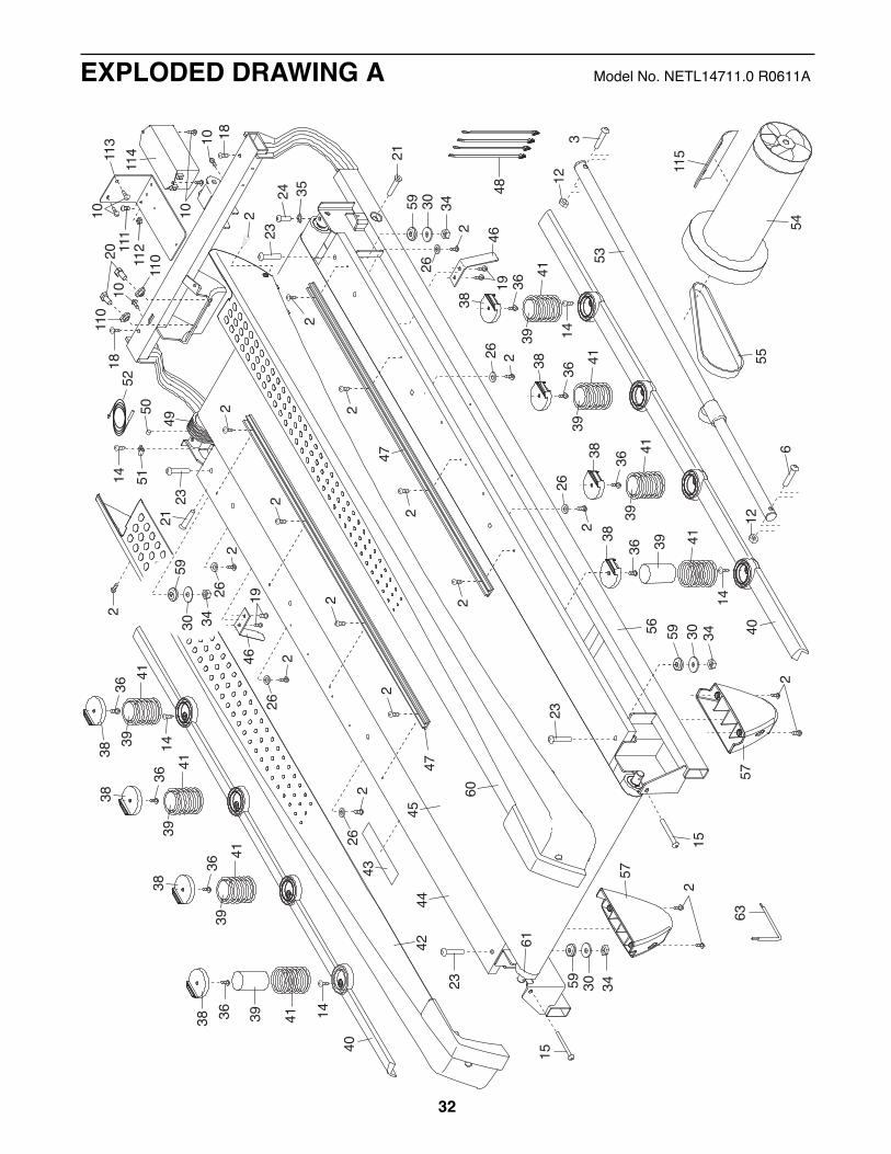
PART LIST Model No. NETL14711.0 R0611A
Key No. Qty. Description Key No. Qty. Description1 14 #8 x 1/2" Screw2 80 #8 x 3/4" Screw3 1 3/8" x 2" Bolt4 6 5/16" x 1 1/4" Bolt5 4 5/16" x 1" Screw6 1 3/8" x 1 3/4" Bolt7 4 3/8" x 2 3/4" Screw8 4 3/8" x 1 1/4" Screw9 4 #10 x 3/4" Screw10 13 #8 x 1/2" Ground Screw11 8 5/16" Star Washer12 2 3/8" Nut13 4 3/8" Star Washer14 13 #8 x 3/4" Tek Screw15 2 Idler Roller Screw16 1 3/8" x 1 1/2" Bolt17 2 3/8" x 1 3/4" Wheel Bolt18 2 #8 x 1 3/4" Screw19 9 #8 x 1/2" Washer Head Screw20 2 5/16" Motor Screw21 2 1/2" x 2 1/4" Bolt22 2 3/8" x 1" Bolt23 4 5/16" x 1 3/4" Shoulder Bolt24 1 1/4" x 1" Screw25 4 #8 x 1" Screw26 6 #8 Flat Washer27 1 UK Power Cord28 1 Base Ground Wire29 1 3/8" x 2" Hex Head Bolt30 4 5/16" Flat Washer31 2 5/16" Cage Nut32 2 1/2" Nut33 6 3/8" Jam Nut34 4 5/16" Nut35 1 1/4" Star Washer36 8 1/4" x 7/8" Flat Head Screw37 1 Right Outside Handrail Cover38 8 Isolator Top39 8 Isolator40 2 Isolator Bottom41 8 Isolator Spring42 1 Left Foot Rail43 1 Caution Decal44 1 Walking Platform45 1 Walking Belt46 2 Belt Guide47 2 Foot Rail Track48 4 Cable Tie49 1 Drive Roller/Pulley50 1 Magnet
51 1 Reed Switch Clip52 1 Reed Switch53 1 Storage Latch54 1 Drive Motor55 1 Motor Belt56 1 Frame57 2 Rear Foot58 1 Frame Cap Cover59 4 Rubber Cushion60 1 Right Foot Rail61 1 Idler Roller62 1 Frame Cap63 1 Hex Key64 1 Console Base65 1 Motor Hood66 1 Hood Accent67 2 Incline Frame Spacer68 3 Hood Clip69 1 Incline Motor70 1 Incline Frame71 2 Frame Spacer72 1 Controller73 1 Controller Plate74 2 Hood Post75 1 Power Switch76 1 Power Cord77 1 Grommet78 1 Belly Pan79 1 Left Handrail Grip80 1 Left Outside Handrail Cover81 1 Upright Wire82 1 Left Base Cover83 1 Right Base Cover84 1 Right Inside Handrail Cover85 1 Left Inside Handrail Cover86 1 Right Handrail Grip87 1 Right Handrail88 1 Left Handrail89 1 Left Upright90 1 Right Upright91 2 Warning Decal92 4 Base Pad93 1 Crossbar94 1 Base95 1 Right Wheel Cap96 1 Left Wheel Cap97 2 Wheel98 1 Key/Clip99 1 Cable Tie100 1 Audio Wire

31
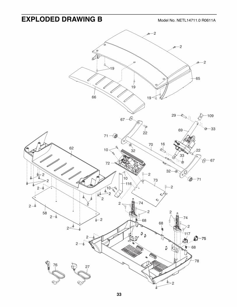
Key No. Qty. Description Key No. Qty. Description101 1 Module Housing102 1 Console Back103 1 Console104 1 Console Frame105 1 Console Ground Wire106 2 Console Clamp107 1 Left Tray108 1 Right Tray109 1 Incline Stop Bracket110 2 Motor Bushing
111 1 #8 x 3/4" Machine Bolt112 1 #8 Nut113 1 Filter Bracket114 1 Filter115 1 Motor Isolator116 1 Grounding Bracket117 1 Receptacle118 1 Chest Strap119 1 Sensor
* – Userʼs Manual
Note: Specifications are subject to change without notice. For information about ordering replacement parts, seethe back cover of this manual. *These parts are not illustrated.
53
23
23
1946
43
49
56
24
18
18
54
4244
60
47
2
47
343059
23
63
52
556
12
3
4619
5014 51
21
21
35
45
2
2
2
12
2
2
2
22
2
10
48
23
153430
57
2
59
6115
30 3457
2
59
38 39
40
41
14
3941
36
36
36 413938
3941
3638
3941
36
38
38
3941
36
3839
4136
38
14
3941
3638
40
2
26
26 2
262
262
262
343059
262
14
14
2010
1011
3
10
114
110
110
111
112
115
32
EXPLODED DRAWING A Model No. NETL14711.0 R0611A
66
742
68
75
10
273
3369
67
71
16
33
70
67
71
65
2
2
19
29
2
32
32
72
742 2
2
78
19
19
22
22
2
62
2
22
22
582
2
2
2
268
68
2
2
2
109
75117
10116
2776
10
EXPLODED DRAWING B Model No. NETL14711.0 R0611A
33

89
94
922
9517
1797
9633
92
92
7138 90
77
7
13
4
86
411
581
81
82
83
1492 8
2
33
10
115
91
28
97 14
14
14
33
33
7
7
91
31
7980
22
2
22
85
88
31
87
37
22
84
2
34
EXPLODED DRAWING C Model No. NETL14711.0 R0611A

98100
9
93
1
107
108
64
2525
106
106
104
10510
1
2
101
102
103
2
2
2
22
2
1
1
2
99
9
2
11
1
1 1
1
1
411
411
118
119
35
EXPLODED DRAWING D Model No. NETL14711.0 R0611A

Part No. 311699 R0611A Printed in China © 2011 ICON IP, Inc.
ORDERING REPLACEMENT PARTSTo order replacement parts, see the front cover of this manual. To help us assist you, please be prepared to pro-vide the following information when contacting us:
• the model number and the serial number of the product (see the front cover of this manual)
• the name of the product (see the front cover of this manual)
• the key number and description of the replacement part(s) (see the PART LIST and the EXPLODEDDRAWING near the end of this manual)
RECYCLING INFORMATIONThis electronic product must not be disposed of in municipal waste. To pre-serve the environment, this product must be recycled after its useful life asrequired by law.
Please use recycling facilities that are authorized to collect this type of waste inyour area. In doing so, you will help to conserve natural resources and improveEuropean standards of environmental protection. If you require more informationabout safe and correct disposal methods, please contact your local city office orthe establishment where you purchased this product.