Embed Size (px)
Citation preview
Using CIM for electrical data management
in nuclear power plants
EDFAnne-Sophie HINTZY
Aurélie DEHOUCK Eric LAMBERT
| 2
OVERVIEW
CIMug Using CIM for electrical data management in nuclear power plants | 06/2016
EDF
1. EDF « SPOC » PROJECT
2. NUCLEAR POWER PLANTS ELECTRICAL NETWORK
3. MODELLING THE NETWORK
ISSUES FOUND AND CHOICES MADE FOR THE PROJECT
CONCLUSION
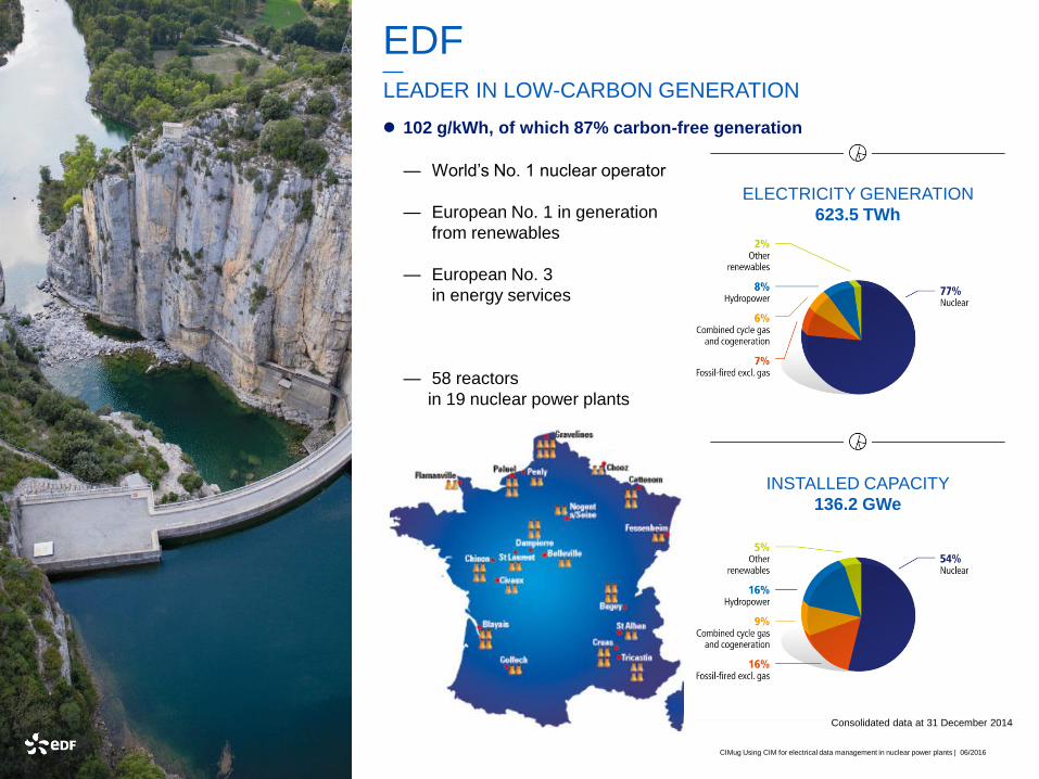
EDFLEADER IN LOW-CARBON GENERATION
102 g/kWh, of which 87% carbon-free generation
— World’s No. 1 nuclear operator
— European No. 1 in generation
from renewables
— European No. 3
in energy services
— 58 reactors
in 19 nuclear power plants
ELECTRICITY GENERATION
623.5 TWh
INSTALLED CAPACITY
136.2 GWe
Consolidated data at 31 December 2014
CIMug Using CIM for electrical data management in nuclear power plants | 06/2016
| 4
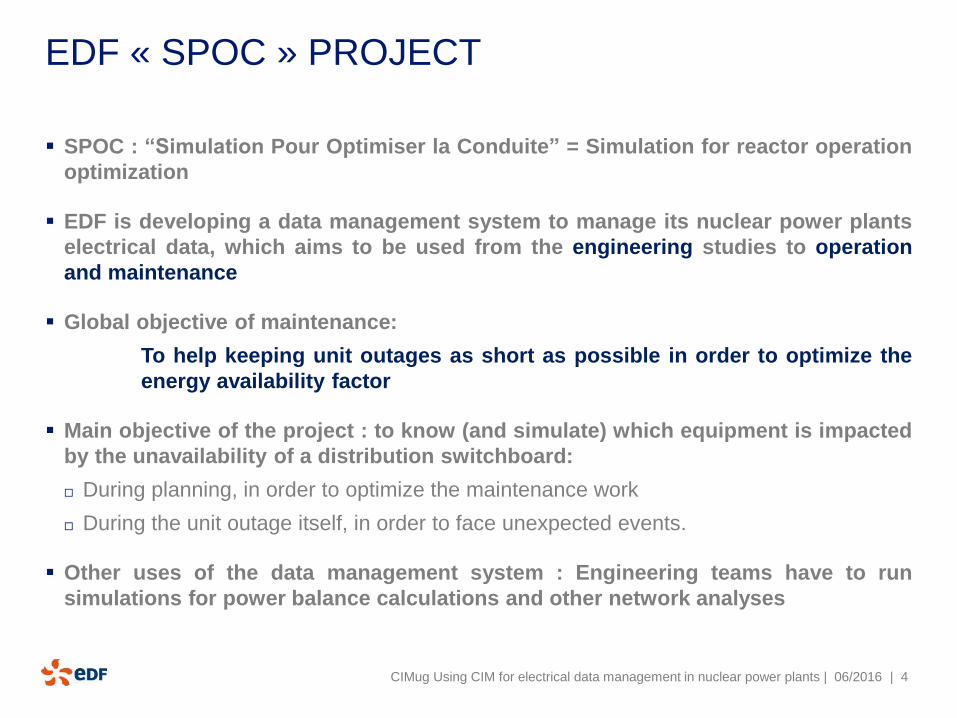
EDF « SPOC » PROJECT
SPOC : “Simulation Pour Optimiser la Conduite” = Simulation for reactor operation
optimization
EDF is developing a data management system to manage its nuclear power plants
electrical data, which aims to be used from the engineering studies to operation
and maintenance
Global objective of maintenance:
To help keeping unit outages as short as possible in order to optimize the
energy availability factor
Main objective of the project : to know (and simulate) which equipment is impacted
by the unavailability of a distribution switchboard:
During planning, in order to optimize the maintenance work
During the unit outage itself, in order to face unexpected events.
Other uses of the data management system : Engineering teams have to run
simulations for power balance calculations and other network analyses
CIMug Using CIM for electrical data management in nuclear power plants | 06/2016
| 5
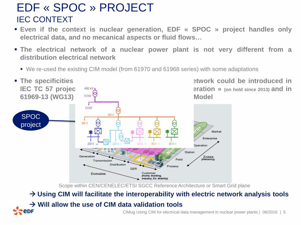
EDF « SPOC » PROJECT IEC CONTEXT Even if the context is nuclear generation, EDF « SPOC » project handles only
electrical data, and no mecanical aspects or fluid flows…
The electrical network of a nuclear power plant is not very different from a
distribution electrical network
We re-used the existing CIM model (from 61970 and 61968 series) with some adaptations
The specificities of generation electric distribution network could be introduced in
IEC TC 57 project 61970-458 « CIM extension to Generation » (on hold since 2013) and in
61969-13 (WG13) Common Distribution Power System Model
Using CIM will facilitate the interoperability with electric network analysis tools
Will allow the use of CIM data validation toolsCIMug Using CIM for electrical data management in nuclear power plants | 06/2016
SPOC
project
Scope within CEN/CENELEC/ETSI SGCC Reference Architecture or Smart Grid plane
| 6
USE
CASES
OF
« SPOC »
PROJECT
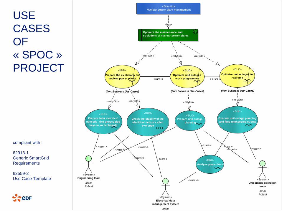
compliant with :
62913-1
Generic SmartGrid
Requirements
62559-2
Use Case Template
CIMug Using CIM for electrical data management in nuclear power plants | 06/2016
Package: Domain Ov erv iew
«Domain»
Nuclear power plant management
Optimize the maintenance and
ev olutions of nuclear power plants
BCBC
(from Business Use Cases)
«BUC»
Optimize unit outages
work programmes
(from Business Use Cases)
«BUC»
Optimize unit outages
work programmes
(from Business Use Cases)
«BUC»
Prepare the ev olutions on
nuclear power plants
(from Business Use Cases)
«BUC»
Prepare the ev olutions on
nuclear power plants
(from Business Use Cases)
«BUC»
Optimize unit outages in
real-time
(from Business Use Cases)
«BUC»
Optimize unit outages in
real-time
(from System Use Case)
«SUC»
Analyse power loss
(from System Use Case)
«SUC»
Check the stability of the
electrical network after
ev olution
(from System Use Case)
«SUC»
Prepare futur electrical
network - find unoccupied
bays in switchboards
(from System Use Case)
«SUC»
Prepare unit outage
planning
(from System Use Case)
«SUC»
Execute unit outage planning
and face unexpected ev ents
«System»
Electrical data
management system
(from
Roles)
«System»
Engineering team
(from
Roles)
«System»
Unit outage operation
team
(from
Roles)
«has»
<<use>>
«relyOn»
«relyOn»
<<use>> <<use>>
<<use>>
«relyOn»
<<use>><<use>><<use>>
«relyOn»
«relyOn»
<<use>> <<use>>
<<use>>
«relyOn»
<<use>>
<<use>>
«relyOn»
| 7
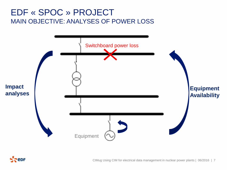
EDF « SPOC » PROJECT MAIN OBJECTIVE: ANALYSES OF POWER LOSS
Switchboard power loss
Equipment
Impact
analysesEquipment
Availability
CIMug Using CIM for electrical data management in nuclear power plants | 06/2016
| 8
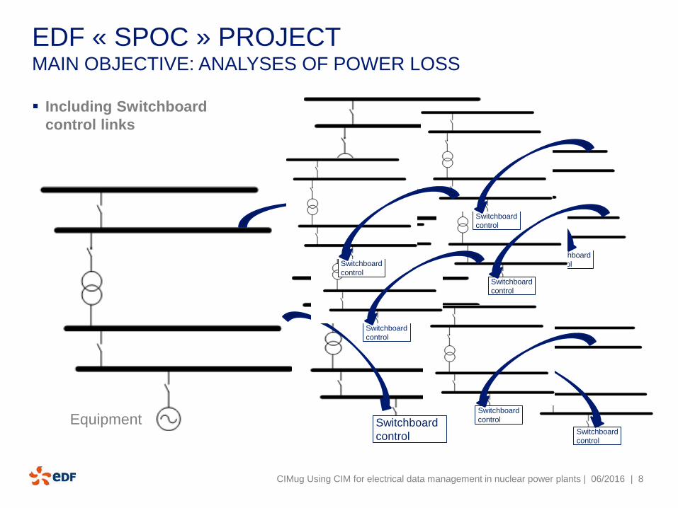
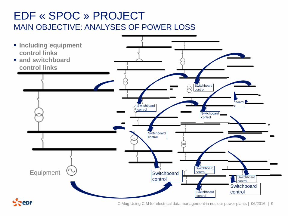
EDF « SPOC » PROJECTMAIN OBJECTIVE: ANALYSES OF POWER LOSS
CIMug Using CIM for electrical data management in nuclear power plants | 06/2016
Equipment Switchboard
control
Switchboard
control
Switchboard
control
Switchboard
control
Switchboard
control
Switchboard
control
Switchboard
control
Switchboard
control
Switchboard
control
Including Switchboard
control links
| 9
EDF « SPOC » PROJECTMAIN OBJECTIVE: ANALYSES OF POWER LOSS
CIMug Using CIM for electrical data management in nuclear power plants | 06/2016
Control
CabinetEquipment
Including equipment
control links
Switchboard
controlSwitchboard
control
Switchboard
control
Switchboard
control
Switchboard
control
Switchboard
control
Switchboard
control
Switchboard
control
Switchboard
control
Switchboard
control
Switchboard
control
Switchboard
control
Switchboard
control
and switchboard
control links
| 10
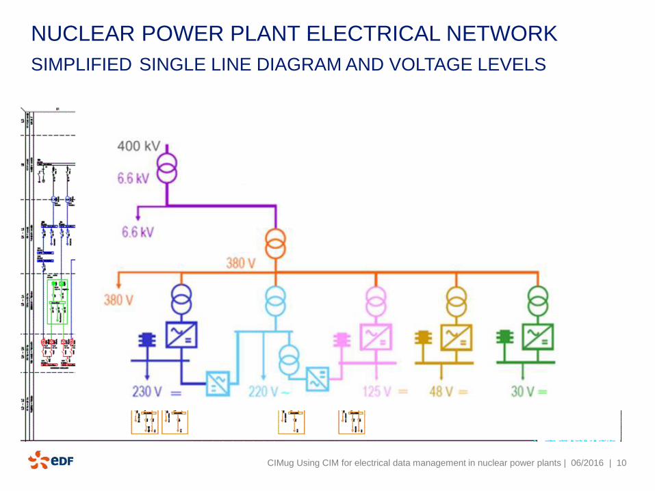
NUCLEAR POWER PLANT ELECTRICAL NETWORK
SIMPLIFIED SINGLE LINE DIAGRAM AND VOLTAGE LEVELS
CIMug Using CIM for electrical data management in nuclear power plants | 06/2016
| 11
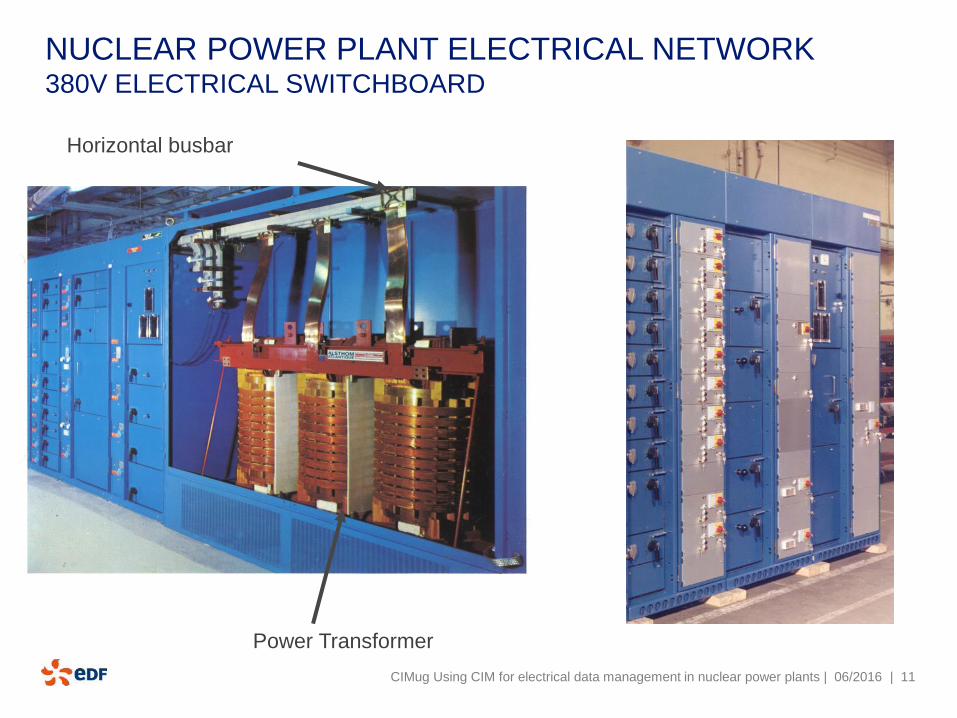
NUCLEAR POWER PLANT ELECTRICAL NETWORK 380V ELECTRICAL SWITCHBOARD
Power Transformer
Horizontal busbar
CIMug Using CIM for electrical data management in nuclear power plants | 06/2016
| 12
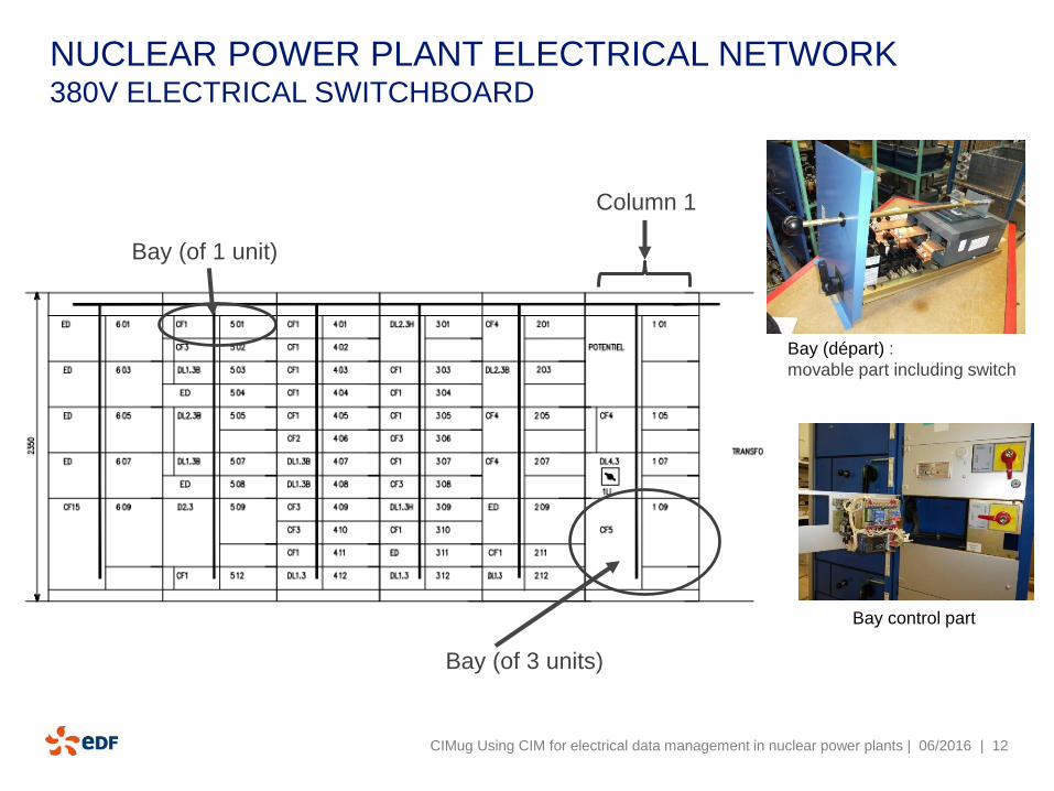
NUCLEAR POWER PLANT ELECTRICAL NETWORK 380V ELECTRICAL SWITCHBOARD
CIMug Using CIM for electrical data management in nuclear power plants | 06/2016
Column 1
Bay (of 3 units)
Bay (of 1 unit)
Bay (départ) :
movable part including switch
Bay control part
| 13
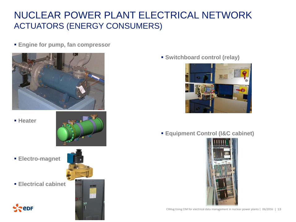
NUCLEAR POWER PLANT ELECTRICAL NETWORKACTUATORS (ENERGY CONSUMERS)
Engine for pump, fan compressor
Heater
Electro-magnet
Electrical cabinet
Switchboard control (relay)
Equipment Control (I&C cabinet)
CIMug Using CIM for electrical data management in nuclear power plants | 06/2016
| 14
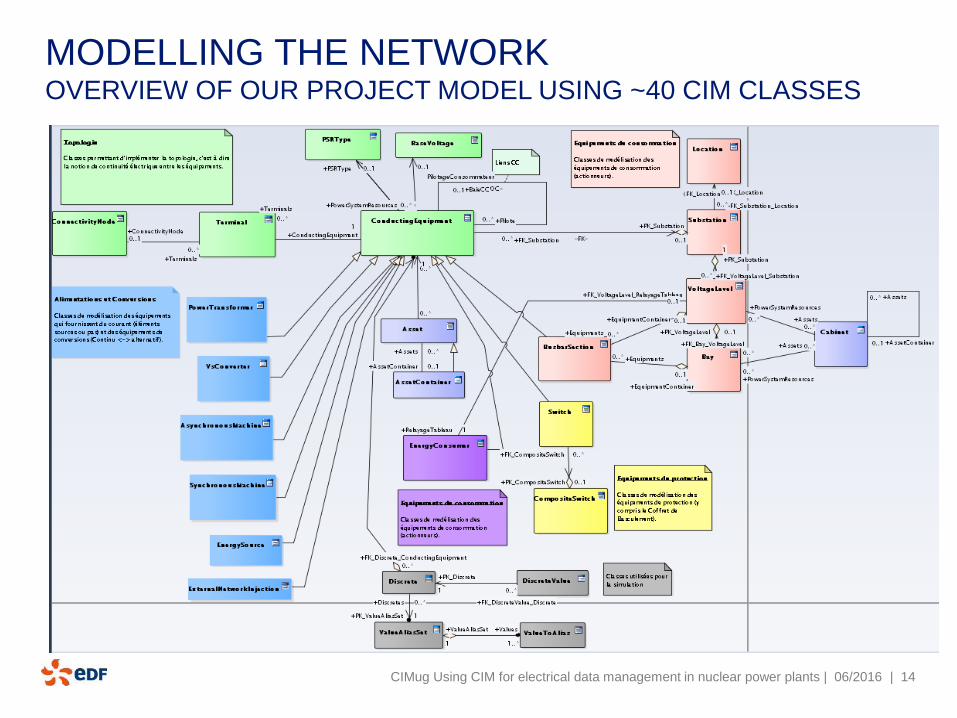
MODELLING THE NETWORKOVERVIEW OF OUR PROJECT MODEL USING ~40 CIM CLASSES
CIMug Using CIM for electrical data management in nuclear power plants | 06/2016
| 15
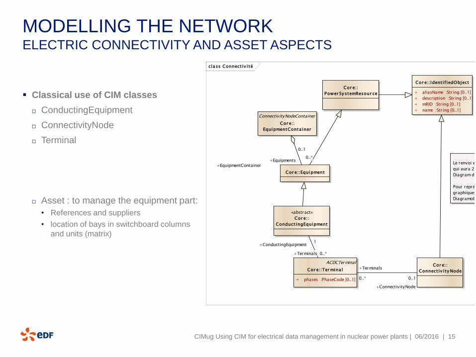
MODELLING THE NETWORKELECTRIC CONNECTIVITY AND ASSET ASPECTS
Classical use of CIM classes
ConductingEquipment
ConnectivityNode
Terminal
Asset : to manage the equipment part:
• References and suppliers
• location of bays in switchboard columns
and units (matrix)
CIMug Using CIM for electrical data management in nuclear power plants | 06/2016
class Connect iv ité
Cor e::Equipment
Cor e::
Power Sy stemResour ce
ConnectivityNodeContainer
Cor e::
EquipmentConta iner
«abstract»
Cor e::
Conduct ingEquipment
ACDCTerminal
Cor e::Ter mina l
+ phases :PhaseCode [0..1]
Cor e::
Connect iv ity Node
Cor e::Ident if iedObject
+ aliasName :String [0..1]
+ description :String [0..1]
+ mRID :String [0..1]
+ name :String [0..1]
Le renvoi est un ConnectivityNode
qui aura 2 objets graphiques, sur 2
Diagram distincts (Folio)
Pour représenter les angles droits sur les
graphiques, il faudra utiliser plusieurs
DiagramobjectPoint
+Terminals
0..*
+ConnectivityNode
0..1
+Terminals 0..*
+ConductingEquipment1
+EquipmentContainer
0..1
+Equipments0..*
| 16
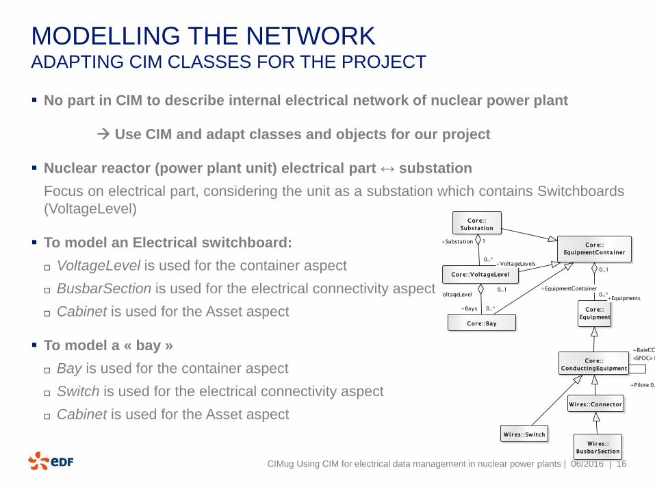
MODELLING THE NETWORKADAPTING CIM CLASSES FOR THE PROJECT
No part in CIM to describe internal electrical network of nuclear power plant
Use CIM and adapt classes and objects for our project
Nuclear reactor (power plant unit) electrical part ↔ substation
Focus on electrical part, considering the unit as a substation which contains Switchboards
(VoltageLevel)
To model an Electrical switchboard:
VoltageLevel is used for the container aspect
BusbarSection is used for the electrical connectivity aspect
Cabinet is used for the Asset aspect
To model a « bay »
Bay is used for the container aspect
Switch is used for the electrical connectivity aspect
Cabinet is used for the Asset aspect
CIMug Using CIM for electrical data management in nuclear power plants | 06/2016
class SPOC
Cor e::
EquipmentConta iner
Cor e::VoltageLev el
Cor e::Bay
Cor e::
Substa t ion
Cor e::
Equipment
W ir es::
Busba r Sect ion
Wir es::Connector
Cor e::
Conduct ingEquipment
W ir es::Switch
+EquipmentContainer
0..1
+Equipments0..*+VoltageLevel
0..1
+Bays 0..*
+Substation 1
+VoltageLevels0..*
+Pilote 0..*
«SPOC» PilotageConsommateur
+BaieCC 0..1
| 17
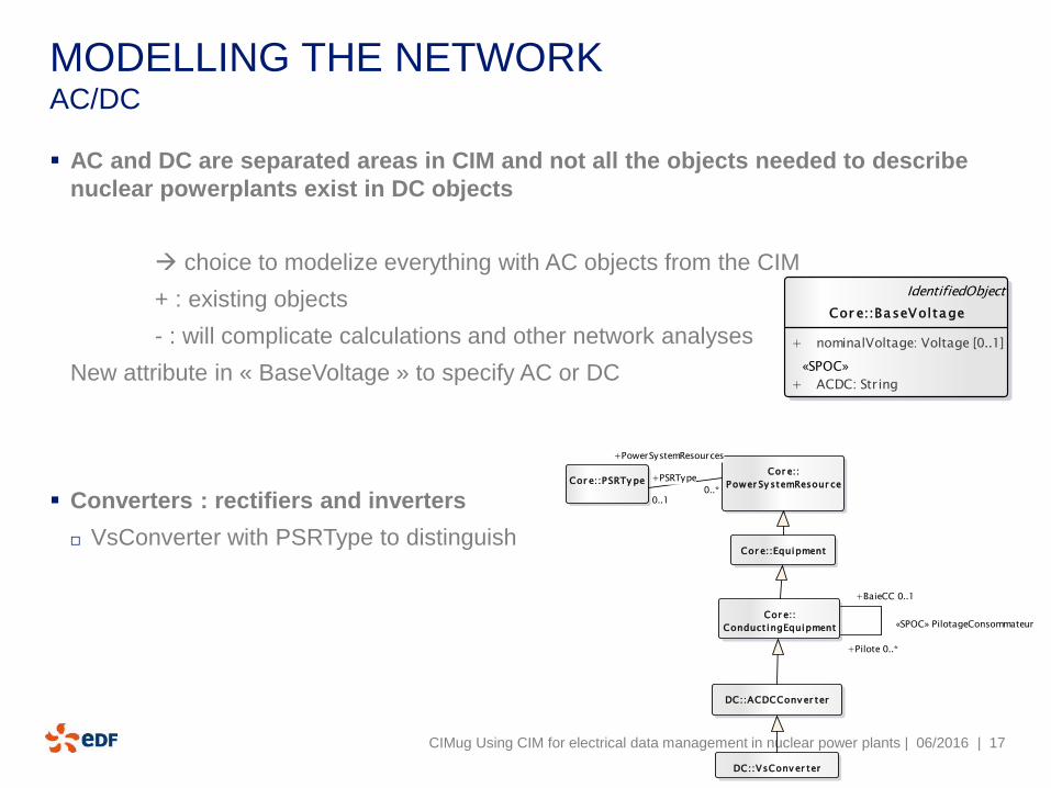
MODELLING THE NETWORK AC/DC
AC and DC are separated areas in CIM and not all the objects needed to describe
nuclear powerplants exist in DC objects
choice to modelize everything with AC objects from the CIM
+ : existing objects
- : will complicate calculations and other network analyses
New attribute in « BaseVoltage » to specify AC or DC
Converters : rectifiers and inverters
VsConverter with PSRType to distinguish
CIMug Using CIM for electrical data management in nuclear power plants | 06/2016
class SPOC - équipements éléc...
IdentifiedObject
Cor e::BaseVoltage
+ nominalVoltage: Voltage [0..1]
«SPOC»
+ ACDC: String
class SPOC
Cor e::PSRTy peCor e::
Power Sy stemResour ce
DC::VsConv er ter
DC::ACDCConv er ter
Cor e::
Conduct ingEquipment
Cor e::Equipment
+PowerSystemResources
0..*
+PSRType
0..1
+Pilote 0..*
«SPOC» PilotageConsommateur
+BaieCC 0..1
| 18
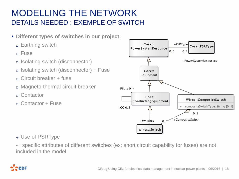
MODELLING THE NETWORK DETAILS NEEDED : EXEMPLE OF SWITCH
Different types of switches in our project:
Earthing switch
Fuse
Isolating switch (disconnector)
Isolating switch (disconnector) + Fuse
Circuit breaker + fuse
Magneto-thermal circuit breaker
Contactor
Contactor + Fuse
Use of PSRType
- : specific attributes of different switches (ex: short circuit capability for fuses) are not
included in the model
CIMug Using CIM for electrical data management in nuclear power plants | 06/2016
class SPOC
Cor e::PSRTy peCor e::
Power Sy stemResour ce
Cor e::
Conduct ingEquipment
Wir es::Switch
Cor e::
Equipment
Wir es::CompositeSwitch
+ compositeSwitchType: String [0..1]
+Pilote 0..*
«SPOC» PilotageConsommateur
+BaieCC 0..1
+PowerSystemResources
0..*
+PSRType
0..1
+CompositeSwitch
0..1
+Switches 0..*
| 19
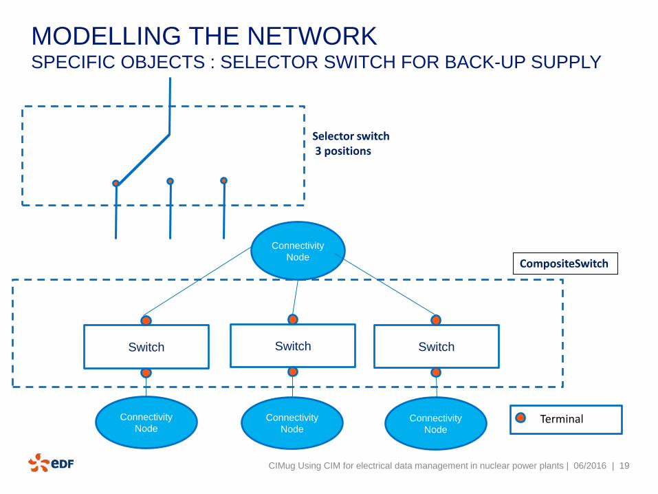
MODELLING THE NETWORKSPECIFIC OBJECTS : SELECTOR SWITCH FOR BACK-UP SUPPLY
CIMug Using CIM for electrical data management in nuclear power plants | 06/2016
Selector switch3 positions
Switch Switch Switch
Connectivity
Node
Connectivity
NodeTerminal
CompositeSwitch
Connectivity
NodeConnectivity
Node
| 20
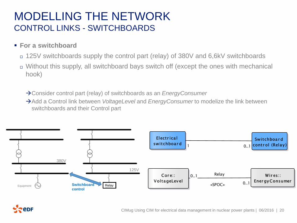
MODELLING THE NETWORK CONTROL LINKS - SWITCHBOARDS
For a switchboard
125V switchboards supply the control part (relay) of 380V and 6,6kV switchboards
Without this supply, all switchboard bays switch off (except the ones with mechanical
hook)
Consider control part (relay) of switchboards as an EnergyConsumer
Add a Control link between VoltageLevel and EnergyConsumer to modelize the link between
switchboards and their Control part
CIMug Using CIM for electrical data management in nuclear power plants | 06/2016
Equipment Switchboard
control
125V
Relay
380V
class SPOC
Switchboar d
contr ol (Relay )
Electr ica l
switchboar d
Wir es::
Ener gy Consumer
Cor e::
VoltageLev el
0..1 Relay
«SPOC» 0..1
0..11
| 21
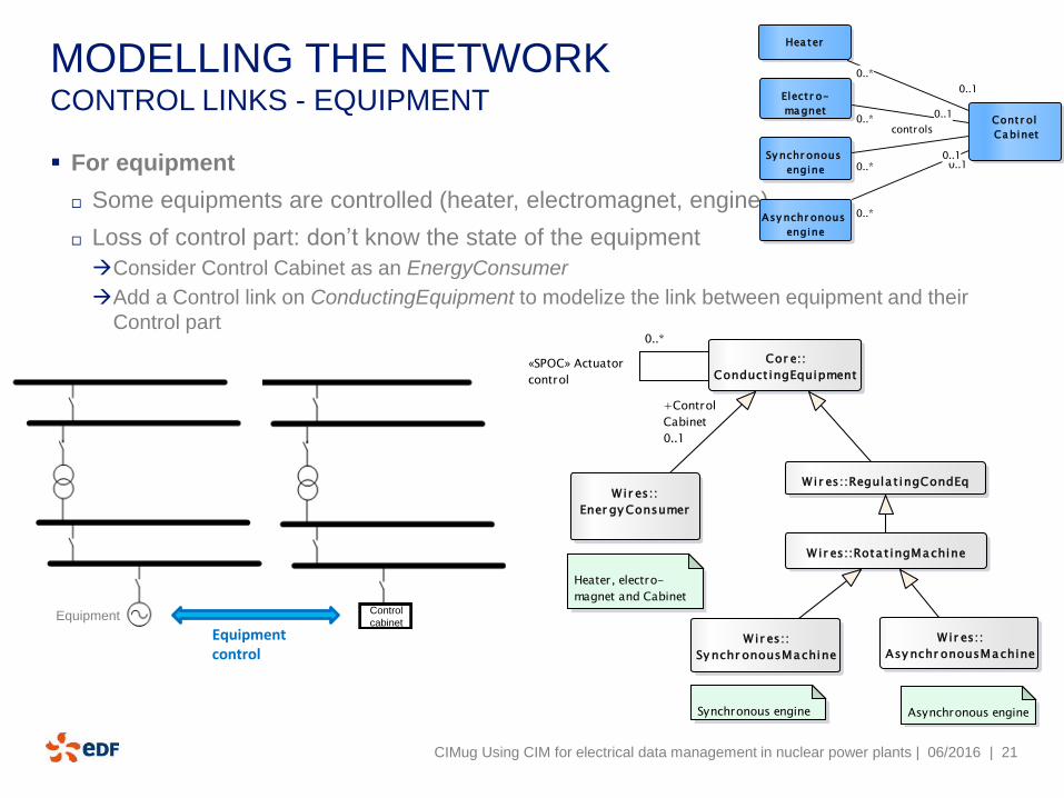
MODELLING THE NETWORK CONTROL LINKS - EQUIPMENT
For equipment
Some equipments are controlled (heater, electromagnet, engine)
Loss of control part: don’t know the state of the equipment
Consider Control Cabinet as an EnergyConsumer
Add a Control link on ConductingEquipment to modelize the link between equipment and their
Control part
CIMug Using CIM for electrical data management in nuclear power plants | 06/2016
Control
cabinet
Equipment control
Equipment
cla ss SPOC
Contr ol
Cabinet
Sy nchr onous
engine
Hea ter
Electr o-
magnet
Asy nchr onous
engine
0..*0..1
0..*
0..10..*0..1
0..*
controls
0..1
class SPOC
Wir es::
Asy nchr onousMachine
Wir es::
Sy nchr onousMachine
Wir es::
Ener gy Consumer
Cor e::
Conduct ingEquipment
Wir es::Rota t ingMachine
Wir es::Regula t ingCondEq
Heater, electro-
magnet and Cabinet
Synchronous engine Asynchronous engine
+Control
0..*
«SPOC» Actuator
control
+Control
Cabinet
0..1

| 22
EDF « SPOC » PROJECTMAIN OBJECTIVE: ANALYSES OF POWER LOSS
CIMug Using CIM for electrical data management in nuclear power plants | 06/2016
Control
CabinetEquipment
Including equipment
control links
Switchboard
controlSwitchboard
control
Switchboard
control
Switchboard
control
Switchboard
control
Switchboard
control
Switchboard
control
Switchboard
control
Switchboard
control
Switchboard
control
Switchboard
control
Switchboard
control
Switchboard
control
and switchboard
control links
| 23
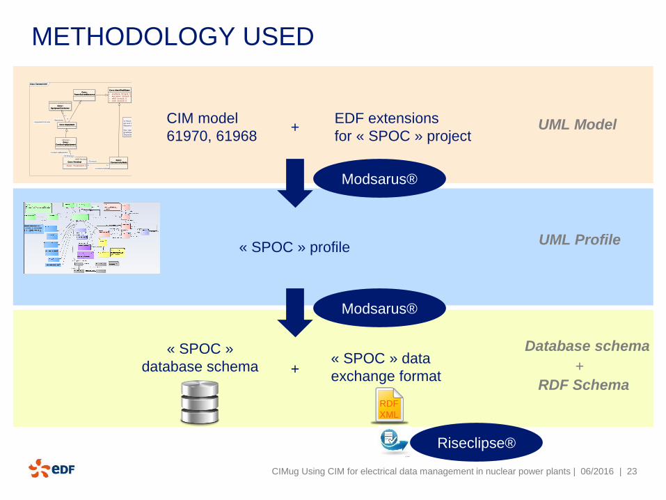
METHODOLOGY USED
CIMug Using CIM for electrical data management in nuclear power plants | 06/2016
CIM model
61970, 61968
EDF extensions
for « SPOC » project+ UML Model
UML Profile
Database schema
RDF Schema
+
« SPOC » profile
« SPOC »
database schema« SPOC » data
exchange format
class Connect iv ité
Cor e::Equipment
Cor e::
Power Sy stemResour ce
ConnectivityNodeContainer
Cor e::
EquipmentConta iner
«abstract»
Cor e::
Conduct ingEquipment
ACDCTerminal
Cor e::Ter mina l
+ phases :PhaseCode [0..1]
Cor e::
Connect iv ity Node
Cor e::Ident if iedObject
+ aliasName :String [0..1]
+ description :String [0..1]
+ mRID :String [0..1]
+ name :String [0..1]
Le renvoi est un ConnectivityNode
qui aura 2 objets graphiques, sur 2
Diagram distincts (Folio)
Pour représenter les angles droits sur les
graphiques, il faudra utiliser plusieurs
DiagramobjectPoint
+Terminals
0..*
+ConnectivityNode
0..1
+Terminals 0..*
+ConductingEquipment1
+EquipmentContainer
0..1
+Equipments0..*
+
RDF
XML
Modsarus®
Modsarus®
Riseclipse®
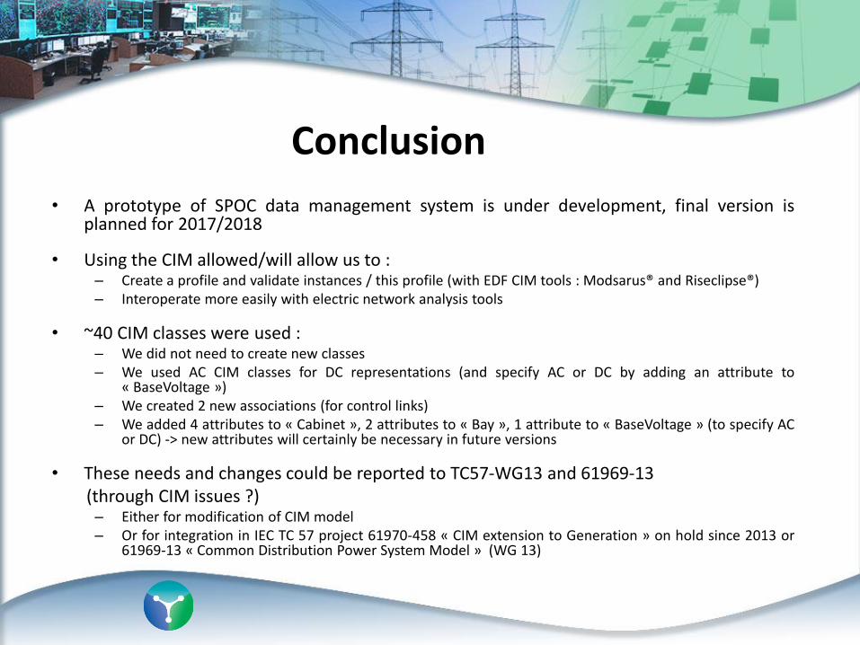
Conclusion
• A prototype of SPOC data management system is under development, final version isplanned for 2017/2018
• Using the CIM allowed/will allow us to :– Create a profile and validate instances / this profile (with EDF CIM tools : Modsarus® and Riseclipse®)– Interoperate more easily with electric network analysis tools
• ~40 CIM classes were used :– We did not need to create new classes– We used AC CIM classes for DC representations (and specify AC or DC by adding an attribute to
« BaseVoltage »)– We created 2 new associations (for control links)– We added 4 attributes to « Cabinet », 2 attributes to « Bay », 1 attribute to « BaseVoltage » (to specify AC
or DC) -> new attributes will certainly be necessary in future versions
• These needs and changes could be reported to TC57-WG13 and 61969-13(through CIM issues ?)– Either for modification of CIM model– Or for integration in IEC TC 57 project 61970-458 « CIM extension to Generation » on hold since 2013 or
61969-13 « Common Distribution Power System Model » (WG 13)


![ETSI ISG CIM · [JSON-LD] 20170608 Introduction to ISG CIM CIM-002-UC CIM -003 GAP CIM-004-APIprelim CIM-005-DPP CIM-001-AB ) CIM-006-MOD0. Timeline in ToR 02/2017 First General Meeting](https://img.pdfslide.net/doc/110x75/6002860fd1e0f63f360db5f2/etsi-isg-cim-json-ld-20170608-introduction-to-isg-cim-cim-002-uc-cim-003-gap.jpg)