Embed Size (px)
Citation preview

Simon Manser, BP Exploration for Hydro14
Using Close Range Photogrammetry to meet Offshore Platform Construction and Installation Requirements
For External Presentation
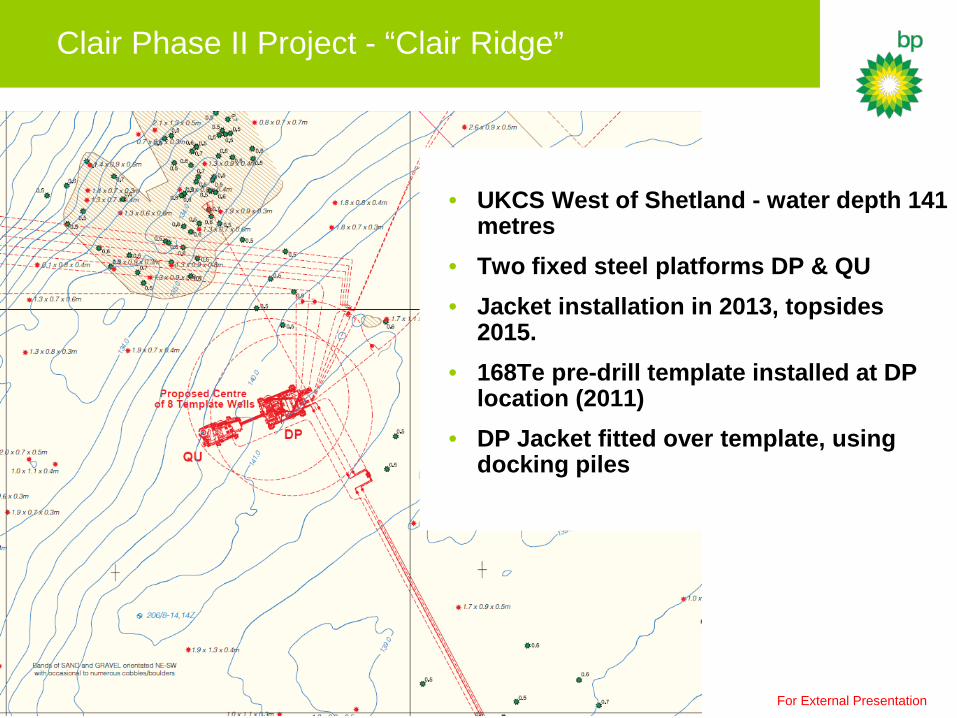
Clair Phase II Project - “Clair Ridge”
• UKCS West of Shetland - water depth 141
metres • Two fixed steel platforms DP & QU • Jacket installation in 2013, topsides
2015. • 168Te pre-drill template installed at DP
location (2011) • DP Jacket fitted over template, using
docking piles
For External Presentation

Photogrammetry – • Delivering 3D spatial models from 2D photos MEEX – Metrology in Extreme Environments • Accuracy:
• Achievable -1:5000 • Quoted - 1:2000
MEEX – Equipment • Surface Photogrammetry acquired using: • Canon EOS 5D Mark II“Full Frame” (21mpix) • Two lenses, 17-40mm & 70-200mm • Subsea Photogrammetry acquired using: • Kongsberg OE14-208 ROV mounted camera (5mpix) • Equivalent to 38-140mm
Fit Esic Photogrammetry
Kongsberg OE14-208
For External Presentation

Fit Esic Processing Methodology
Free Bundle Adjustment – Minimal Control • Requires 20 images for initial free bundle adjustment
• Uses a combination of triangulation and resection
• Minimum of one scale bar to be visible in approximately 10% of the images to determine the camera parameters
• Adjustment is reliant on Epipolar Geometry
• Model globally expanded using regular free bundle adjustments with self calibration
For External Presentation

Subsea Installation Positioning Tolerances
• Template - As-Built Requirement: • Template orientation: ±0.5° • Global template location: ±0.5m • Template level: ±0.1° Installation & as-built achieved using: • Wideband LBL array • CDL ring laser gyros & mini-tilt package • Digi-quartz leveling Template as-built used for photogrammetric model orientation
• Docking Piles - As-Built Requirement : • Pile verticality: ±0.1° • Pile separation: ±50mm As-built results derived using:
• Fit Esic “MeeX” close range photogrammetry • Verification by LBL & attitude sensor
Temporary Pile Docking Guides
For External Presentation

Introducing…
• Pile Measurement 1) Formation of best fit plane using collinear equations
2) Define the intersecting line between two planes (plane geometry)
Subsea Photogrammetric Docking Pile Computation
Image 1 Image 2
Edge of Pile
(from image 2)
Line of Intersection
Determining Pile Centre 3) Combining multiple lines of intersection with tangential plane equations
Image 1 Image 2
Pile
Tangential Plane
TOP VIEW
Line of Intersection
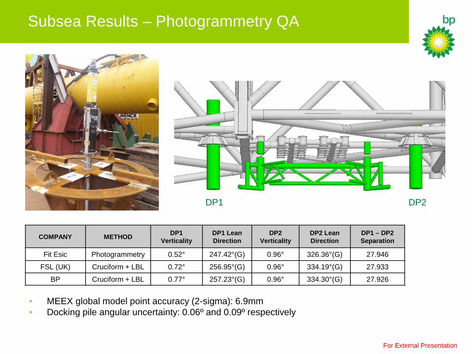
• MEEX global model point accuracy (2-sigma): 6.9mm • Docking pile angular uncertainty: 0.06º and 0.09º respectively
Subsea Results – Photogrammetry QA
COMPANY METHOD DP1 Verticality
DP1 Lean Direction
DP2 Verticality
DP2 Lean Direction
DP1 – DP2 Separation
Fit Esic Photogrammetry 0.52° 247.42°(G) 0.96° 326.36°(G) 27.946
FSL (UK) Cruciform + LBL 0.72° 256.95°(G) 0.96° 334.19°(G) 27.933
BP Cruciform + LBL 0.77° 257.23°(G) 0.96° 334.30°(G) 27.926
For External Presentation
DP1 DP2

Jacket Topside Dimensional Control
• Jacket Installation Positioning (HMC/DOF) • DP Jacket installed over existing piles.
• QU installed relative to DP
• Photogrammetry Scope of Work (Fit Esic)
The scope of work was to:
• Survey the flange/nozzle connections for pre-fabrication of hook up spools
• Confirm leg ovality at cut level for primary and secondary stab-in cones (6 in total)
Using existing imagery Fit Esic also delivered:
• The verticality and orientation of the Jacket
• The planarity of the leg cuts
• The leg separation post installation
• The leg cut elevation
• The location (surface and seabed) of QU relative to DP
For External Presentation

Model Processing: Defining the Z-plane for verticality
• All leg cuts (12 in total) processed with existing imagery to define Z reference plane • Retrospective process that is not possible using traditional dimensional control techniques
For External Presentation

Introducing… Model Processing: Creating & Orientating the Models
The Process
1) Define the CRS 2) Create a surface model 3) Orientate the surface model 4) Merge the surface model with the jacket
yard as-built model
For External Presentation

Model Processing: Jacket Verticality Results
DP Platform DOF (UK) HMC Fit Esic Pitch 0.25º 0.09º 0.08º
Roll -0.32º -0.03º -0.05º
QU Platform DOF (UK) HMC Fit Esic Pitch 0.05º 0.01º 0.05º
Roll -0.03º -0.01º -0.05º
• DOF (UK) results derived from Octans HPR sensor • HMC results derived from optical level
Verticality Results
For External Presentation

Surface Photogrammetric Model Accuracy
Relative Model – Initial Scope of Work Model Final Model Accuracy (mm) at 2 Sigma
QU 2.2 DP Tower West 0.5 DP Tower East 1.4
Model Best Fit RMS error (mm) QU 2.4
DP Tower West 4.6 DP Tower East 2.6
Global Model – Retrospective Processing for Additional Scope of Work
Relative free bundle adjustment
Relative model best fitted to global control
For External Presentation
Clair Phase II Project - “Lessons Learned”
Primary Benefits (MEEX Close Range Photogrammetry)
• Efficient – fast acquisition resulting in significant time saving • Safe - reduced HSSE exposure • Flexible - ancillary data provides retrospective processing capability without re-
mobilising to the field. Primary Constraint • Processing time - suitable when results are required within 2-4 weeks.
For External Presentation